EP0770717B1 - Verfahren und Vorrichtung zum pneumatischen Aufnehmen und Zuführen eines Faserbandendes an eine OE-Spinnvorrichtung - Google Patents
Verfahren und Vorrichtung zum pneumatischen Aufnehmen und Zuführen eines Faserbandendes an eine OE-Spinnvorrichtung Download PDFInfo
- Publication number
- EP0770717B1 EP0770717B1 EP96119796A EP96119796A EP0770717B1 EP 0770717 B1 EP0770717 B1 EP 0770717B1 EP 96119796 A EP96119796 A EP 96119796A EP 96119796 A EP96119796 A EP 96119796A EP 0770717 B1 EP0770717 B1 EP 0770717B1
- Authority
- EP
- European Patent Office
- Prior art keywords
- sliver
- feeder
- feed
- open
- spinning device
- Prior art date
- Legal status (The legal status is an assumption and is not a legal conclusion. Google has not performed a legal analysis and makes no representation as to the accuracy of the status listed.)
- Expired - Lifetime
Links
Images

Classifications
-
- D—TEXTILES; PAPER
- D01—NATURAL OR MAN-MADE THREADS OR FIBRES; SPINNING
- D01H—SPINNING OR TWISTING
- D01H9/00—Arrangements for replacing or removing bobbins, cores, receptacles, or completed packages at paying-out or take-up stations ; Combination of spinning-winding machine
- D01H9/18—Arrangements for replacing or removing bobbins, cores, receptacles, or completed packages at paying-out or take-up stations ; Combination of spinning-winding machine for supplying bobbins, cores, receptacles, or completed packages to, or transporting from, paying-out or take-up stations ; Arrangements to prevent unwinding of roving from roving bobbins
- D01H9/185—Transporting cans
-
- B—PERFORMING OPERATIONS; TRANSPORTING
- B65—CONVEYING; PACKING; STORING; HANDLING THIN OR FILAMENTARY MATERIAL
- B65H—HANDLING THIN OR FILAMENTARY MATERIAL, e.g. SHEETS, WEBS, CABLES
- B65H67/00—Replacing or removing cores, receptacles, or completed packages at paying-out, winding, or depositing stations
- B65H67/04—Arrangements for removing completed take-up packages and or replacing by cores, formers, or empty receptacles at winding or depositing stations; Transferring material between adjacent full and empty take-up elements
- B65H67/0428—Arrangements for removing completed take-up packages and or replacing by cores, formers, or empty receptacles at winding or depositing stations; Transferring material between adjacent full and empty take-up elements for cans, boxes and other receptacles
-
- D—TEXTILES; PAPER
- D01—NATURAL OR MAN-MADE THREADS OR FIBRES; SPINNING
- D01H—SPINNING OR TWISTING
- D01H15/00—Piecing arrangements ; Automatic end-finding, e.g. by suction and reverse package rotation; Devices for temporarily storing yarn during piecing
-
- D—TEXTILES; PAPER
- D01—NATURAL OR MAN-MADE THREADS OR FIBRES; SPINNING
- D01H—SPINNING OR TWISTING
- D01H9/00—Arrangements for replacing or removing bobbins, cores, receptacles, or completed packages at paying-out or take-up stations ; Combination of spinning-winding machine
- D01H9/005—Arrangements for replacing or removing bobbins, cores, receptacles, or completed packages at paying-out or take-up stations ; Combination of spinning-winding machine for removing empty packages or cans and replacing by completed (full) packages or cans at paying-out stations; also combined with piecing of the roving
- D01H9/008—Arrangements for replacing or removing bobbins, cores, receptacles, or completed packages at paying-out or take-up stations ; Combination of spinning-winding machine for removing empty packages or cans and replacing by completed (full) packages or cans at paying-out stations; also combined with piecing of the roving for cans
-
- B—PERFORMING OPERATIONS; TRANSPORTING
- B65—CONVEYING; PACKING; STORING; HANDLING THIN OR FILAMENTARY MATERIAL
- B65H—HANDLING THIN OR FILAMENTARY MATERIAL, e.g. SHEETS, WEBS, CABLES
- B65H2701/00—Handled material; Storage means
- B65H2701/30—Handled filamentary material
- B65H2701/31—Textiles threads or artificial strands of filaments
Definitions
- the present invention relates to a method and an apparatus according to The preamble of claims 1 and 5.
- DE 26 46 313 A1 describes a method and a device for replacement known from sliver cans, in which a sliver end by means of a movable, programmable, controllable clamp on a jug. By means of a suitable movement, the sliver end clamped therein becomes one Feeder fed.
- the feed device is designed such that that it has a sliver feed device, which in the direction of the Clamp is moved.
- the clamp transfers the sliver end to the Feed device, which the fiber sliver end in a clamping area between introduces a delivery roller and a feed trough of the feed device.
- the feed device for the transfer of the End of sliver must be equipped with a movable feed device.
- by handing over the Sliver end not always from the clamp to the feeder ensures that the sliver end on the one hand sufficiently far over the clamp protrudes so that it can be detected in the clamping area of the feed device can, and on the other hand the sliver end not too far over the clamp also protrudes so that when the sliver end is fed into the feed device and the subsequent disintegration device prevents clogging.
- EP 0 348 678 A1 describes a method and a device for pneumatic Introducing a sliver end described in a feed device.
- the sliver end becomes a condenser by means of a mechanical gripper supplied in which there is an air flow.
- the sliver end is by means of the air flow is sucked in and through the condenser Feeder fed.
- the air flow in the condenser is thereby generates that the condenser is supplied with a compressed air nozzle, which in the direction blows onto the condenser outlet.
- a disadvantage of this device is that again a transfer from a mechanical gripper to a pneumatic one System takes place.
- the sliver end must be in a defined Extend the length beyond the mechanical gripper.
- the mechanical grippers connected to the pneumatics for control purposes mechanical tracking of the sliver end and timely release of the Allow sliver so that the sliver end by the condenser in the feed device can be inserted. This means a high one Control engineering and design effort for the transfer of the sliver to the feeder.
- EP 0 360 023 A1 which contains the closest state of the art, one hanging over a can edge
- the sliver end is gripped pneumatically and fed to a splice chamber.
- the Splice chamber In the Splice chamber is the end of the sliver as the beginning of the sliver with one from the Splicing feeder protruding other sliver end.
- the The beginning of the sliver is held under vacuum and one at a distance from Sliver beginning of the sliver by means of overpressure with the from the Splicing feeder hanging sliver end.
- a disadvantage of this The device is that the OE spinning device must recognize when a Sliver has almost run out. The spinning device must then be stopped become.
- this solution also includes: Raw material wasted.
- the object of the present invention is thus, with little constructive Reliable and effortless and low loss of fiber material to create inexpensive device and a corresponding method with which a new sliver can be fed to a spinning device.
- the device that picks up the sliver is considered feeds the working organ of the textile machine.
- a Device for automatically applying a sliver to a OE spinning device is a sliver in which the sliver can be stored in a defined position is, as well as a tape feeder for receiving the in the receiving position submitted sliver and for its introduction provided in the feeder.
- the taping machine will formed by the can in which the fiber tape to be applied to the feeder becomes.
- a is for this purpose the end of the tape in the center of the tape turns in the jug Tape depositors provided.
- the recording of the end of the tape as the new beginning of the tape can be different Way. So it is according to the invention if the belt feeder into the center of the jug between the ribbon windings can be brought to the defined recording of the tape end.
- the belt feeder is particularly easy to find is the Ribbon rug conveniently attached to a jug, wherein a detachable attachment of the tape rammer to the jug usual cans allows.
- the Tape pickup between the tape turns in the center of the jug be feasible.
- the tape pickup and / or tape feeder is pneumatic educated.
- the belt feeder has an essentially tubular, connected to a switchable overpressure / vacuum source Base body, which at its free end a in its length adapted to the length of the tape end to be detected Strainer that extends over a partial circumference of the base body extends.
- the subject matter of the invention is in the pneumatic design of the Belt feeder whose main body in Divided into two chambers, each of which individual, i.e. regardless of the other Chamber, can be switched to negative pressure or positive pressure. hereby becomes both a safe tape take and a safe one Tape delivery guaranteed.
- the invention enables automatic in a simple manner Applying the sliver to the feed device of an OE spinning machine. This ensures that downtime is reduced be, since it is not necessary that a Sliver the operator is immediately on the spot to to carry out the tape application. Rather, this can be done through a Maintenance facility happen, if desired, in the event a spinning machine can also carry out re-spinning.
- OE spinning devices find application; below is intended to be a conventional one as a concrete exemplary embodiment Serve open-end spinning device 1, which will now be described.
- An open-end spinning device 1 is usually part of one Open-end spinning machine 16 on one or both sides of the machine a. Large number of similar, arranged side by side Has open-end spinning devices 1. Any open end spinning device 1 has a spinning element shown in FIG Execution designed for example as a spinning rotor 10 is.
- the spinning rotor 10 is in a known manner by means of a Shaft 100 stored and is in the embodiment shown driven by means of a tangential belt 101.
- the Spinning rotor 10 is arranged in a rotor housing 102, the Interior 103 via a suction pipe connection 104 with a not vacuum source shown is connected.
- a brake 11 can be delivered to the shaft 100 of the spinning rotor, which brake is connected to an actuating lever 13 via a linkage 12 which is only indicated schematically. If the free arm of the actuating lever 13 is acted on in the direction of the arrow P 4 , the brake 11 comes to bear against the shaft 100 of the spinning rotor 10, so that the latter is braked.
- the mechanism, which consists of brake 11, linkage 12 and actuating lever 13, is suitably acted upon by an elastic element against the direction of arrow P 4 , that is to say in the direction of arrow P 5 , so that when an application is ended in the direction of arrow P 4, the brake 11 returns to its release position.
- the elastic element which acts on the mechanism consisting of brake 11, linkage 12 and actuating lever 13, is designed as a compression spring 130, which is supported on the actuating lever 13 on its arm facing the linkage 12 and on a machine part, not shown.
- Feeding device 2 For feeding fibers into the spinning rotor 10 is one Feeding device 2 provided in the embodiment shown from a delivery roller 20 and a feed trough 21 exists, which is pivotally mounted and by a Compression spring 22 is pressed elastically against the delivery roller 20.
- the delivery roller 20 is connected downstream in a housing 23 arranged opening roller 24, which during normal production because of their high speed from one with the help of the Feeding device 2 from a sliver 4 fed from a can 41 Combed fibers, not shown, which by one of the Housing 23 extending into the spinning rotor 10 Fiber feed channel 25 are fed to the spinning rotor 10.
- the fibers lay down in the usual way on a fiber collection point in the spinning rotor 10 from where it passes through the end of a thread 44 recorded and continuously involved in the end of it become.
- the thread 44 is threaded through a thread take-off tube 26 a pair of draw-off rollers 27 are drawn off and onto a spool 28 wound up, which in a known manner by a winding roller 29th is driven.
- Thread tensioning bracket e.g. Thread tensioning bracket, traversing thread guide, Thread return device and thread end preparation device, are not shown in Figure 1 for the sake of clarity Service.
- the open-end spinning device 1 is covered by a cover 105, which has a feed hopper 106, is covered and by a machine frame 107 carried.
- a cover 105 On the cover 105 is one Signal device 15 attached, e.g. in the form of a signal lamp, the one with the thread monitor 14 (usually with interposition a control device, not shown) in terms of control communicates.
- a feed hopper 106 which is used to insert the beginning of the tape 43 relieved in the feed device 2.
- a first such embodiment is shown with the help of Figure 2 explains.
- the axially projecting into the interior of the can 40 End of tape that is related to insertion into this Feeding device 2 of the open-end spinning device 1 the beginning of the band 43 to keep safe, has one for this Length b of at least 100 mm and a maximum of 200 mm as special emphasized advantageous. Is the end of the tape shorter than 100 mm, there is a risk that the belt end from the center of the can 400 is pulled out.
- the end of the tape is longer than 200 mm, it is difficult to center this band end to introduce the can 40.
- the resumption extremely difficult and leads at a later date also to the fact that a longer band section when preparing the End of tape for insertion into the feed device 2 of the open-end spinning device 1 must be separated and removed.
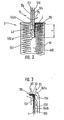
- a belt feeder 55 is also provided, which is designed pneumatically.
- This belt feeder 55 essentially consists of a base body designed as a tube 550, which is closed by a wall 551 at its front end which can be brought into the can center 400.
- the tube wall is designed as a screen 552 on a surface that extends along a generator line over part of the circumference of the tube 550.
- the tube 550 is connected at its end, not shown, to a vacuum source; so that a suction air flow flowing into the tube 550 can be generated in the area of the sieve 552. If the belt feeder 55 is now inserted into the can center 400 and rotated about its longitudinal axis (see arrow P 6 ), the sieve 552 arrives in the region of the belt end forming the later belt start 43 and holds it there.
- the belt feeder 55 can now vertically from the can center 400 be moved upwards. He takes the end of the tape with him.
- the belt feeder 55 is now in front of the feed hopper 106 Open-end spinning device 1 (Fig. 1) brought, and now the band end 43 forming band end is replaced by a suitable one Movement of the tape feeder 55 in this feed hopper 1D6 to in the clamping area between delivery roller 20 and feed trough 21 introduced so that the feed device 2 accommodate the sliver 4 and can carry on.
- the band feeder 55 during the insertion movement into the Can center 400 not to the extreme end of the sliver 4 is moved so that after receiving the sliver 4 through the tape feeder 55 a predetermined length of tape across the end of the tape feeder 55 extends. By moving around 180 ° can then this free end of the sliver 4 in the Feeder 2 are introduced.
- both the chamber 554 and the chamber 555 are subjected to a vacuum.
- the belt feeder 55 is then brought into the correct position for the transfer of the sliver 4 to the feed device 2, which can be done both by rotating it in the direction of arrow P 6 about its longitudinal axis and by pivoting it through 180 °. If the belt feeder 55 is then in front of the feed hopper 106 (see FIG. 3), the chamber 554 is first subjected to excess pressure, so that the beginning of the belt 43 is blown into the feed hopper 106. The belt feeder 55 is then raised in the direction of the arrow P 7 until the partial screen 552b also reaches the area in front of the feed hopper 106.
- the 552 sieve can do more than just two Partial screens 552a and 552b and accordingly more than just two Chambers 554 and 555, which are then also individually controlled will have.
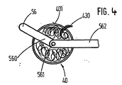
- Figure 4 shows an alternative solution in which the tape end 430 extends outward over the can rim 401 and outside the Can 40 hangs down, here as well as in the previously described Exemplary embodiment of the downwardly projecting band end should have a length that is between 100 mm and 200 mm.
- a belt feeder 56 which is in the essentially in the same manner as that shown in FIG Belt feeder 55 is formed, find application.
- the Belt feeder 56 is attached to the free end of a swivel arm 560, which can be rotated about a pivot axis 561.
- the Pivot axis 561 is located at the end of a support arm 562 which for receiving the tape end 430 with its pivot axis 561 can be placed centrally over the can 40.
- a support arm 562 which for receiving the tape end 430 with its pivot axis 561 can be placed centrally over the can 40.
- the band feeder 56 via lines, not shown with corresponding sources of negative pressure or positive pressure, so that 56 corresponding suction or Compressed air flows can be generated.
- the support arm 562 is in suitably mounted on the open-end spinning machine 16, expediently with the help of a movable along the machine Device, which is thus enabled, more than just to operate an open-end spinning device 1.
- the swivel arm 560 with the Belt feeder 56 brought into the position shown in FIG. 4, in which the pivot axis 561 is essentially centered located above the can 40. Now the swivel arm 560 is at least 360 ° pivoted along the can rim 401, so that the Belt feeder 56 surely passes the belt end 430 and this due to the draft in it in a defined way.
- this belt feeder 56 also works in the same way Way as that belt feeder 55, which with the aid of the second and 3 is described.
- Swivel arm 560 it is of course also possible instead of one Swivel arm 560 to provide another arm if the Kanne 40 instead of the arm is given a rotary movement. Essential is only the relative movement between sliver 4 and Belt feeder 56 so that the sliver 4 in the area of Belt feeder 56 arrives and are picked up by this can.
- Figures 2 and 4 show that the jug can serve itself for the correct presentation of the tape. It is of course also possible, fixed or detachable on the can 40 To attach tape precursors.
Landscapes
- Engineering & Computer Science (AREA)
- Mechanical Engineering (AREA)
- Textile Engineering (AREA)
- Spinning Or Twisting Of Yarns (AREA)
- Replacing, Conveying, And Pick-Finding For Filamentary Materials (AREA)
Applications Claiming Priority (6)
| Application Number | Priority Date | Filing Date | Title |
|---|---|---|---|
| DE4015938 | 1990-05-18 | ||
| DE19904015938 DE4015938A1 (de) | 1990-05-18 | 1990-05-18 | Spinnereianlage |
| DE19904035439 DE4035439A1 (de) | 1990-11-08 | 1990-11-08 | Verfahren und vorrichtung zum automatischen anlegen eines faserbandes an einer textilmaschine |
| DE4035439 | 1990-11-08 | ||
| EP91909136A EP0528884B1 (de) | 1990-05-18 | 1991-05-17 | Verfahren und vorrichtung zum automatischen anlegen eines faserbandes an einer textilmaschine |
| EP95120117A EP0709501B1 (de) | 1990-05-18 | 1991-05-17 | Verfahren zum Kannenwechsel zwischen einem Transportwagen für Flachkannen und einer OE-Spinnmaschine und Transportwagen zur Durchführung des Verfahrens |
Related Parent Applications (2)
| Application Number | Title | Priority Date | Filing Date |
|---|---|---|---|
| EP91909136.3 Division | 1991-12-11 | ||
| EP95120117.7 Division | 1995-12-19 |
Publications (3)
| Publication Number | Publication Date |
|---|---|
| EP0770717A2 EP0770717A2 (de) | 1997-05-02 |
| EP0770717A3 EP0770717A3 (de) | 1997-08-13 |
| EP0770717B1 true EP0770717B1 (de) | 2003-03-19 |
Family
ID=25893312
Family Applications (5)
| Application Number | Title | Priority Date | Filing Date |
|---|---|---|---|
| EP96119796A Expired - Lifetime EP0770717B1 (de) | 1990-05-18 | 1991-05-17 | Verfahren und Vorrichtung zum pneumatischen Aufnehmen und Zuführen eines Faserbandendes an eine OE-Spinnvorrichtung |
| EP91909136A Expired - Lifetime EP0528884B1 (de) | 1990-05-18 | 1991-05-17 | Verfahren und vorrichtung zum automatischen anlegen eines faserbandes an einer textilmaschine |
| EP95106898A Expired - Lifetime EP0668380B1 (de) | 1990-05-18 | 1991-05-17 | Verfahren und Vorrichtung zum automatischen Anlegen eines Faserbandes an einer Textilmaschine |
| EP91909388A Expired - Lifetime EP0528907B2 (de) | 1990-05-18 | 1991-05-17 | Verfahren und vorrichtung zum transportieren von flachkannen zwischen faserbänder be- oder verarbeitenden maschinen oder vorrichtungen |
| EP95120117A Expired - Lifetime EP0709501B1 (de) | 1990-05-18 | 1991-05-17 | Verfahren zum Kannenwechsel zwischen einem Transportwagen für Flachkannen und einer OE-Spinnmaschine und Transportwagen zur Durchführung des Verfahrens |
Family Applications After (4)
| Application Number | Title | Priority Date | Filing Date |
|---|---|---|---|
| EP91909136A Expired - Lifetime EP0528884B1 (de) | 1990-05-18 | 1991-05-17 | Verfahren und vorrichtung zum automatischen anlegen eines faserbandes an einer textilmaschine |
| EP95106898A Expired - Lifetime EP0668380B1 (de) | 1990-05-18 | 1991-05-17 | Verfahren und Vorrichtung zum automatischen Anlegen eines Faserbandes an einer Textilmaschine |
| EP91909388A Expired - Lifetime EP0528907B2 (de) | 1990-05-18 | 1991-05-17 | Verfahren und vorrichtung zum transportieren von flachkannen zwischen faserbänder be- oder verarbeitenden maschinen oder vorrichtungen |
| EP95120117A Expired - Lifetime EP0709501B1 (de) | 1990-05-18 | 1991-05-17 | Verfahren zum Kannenwechsel zwischen einem Transportwagen für Flachkannen und einer OE-Spinnmaschine und Transportwagen zur Durchführung des Verfahrens |
Country Status (8)
| Country | Link |
|---|---|
| US (1) | US5276947A (cs) |
| EP (5) | EP0770717B1 (cs) |
| JP (2) | JPH05508688A (cs) |
| BR (1) | BR9105752A (cs) |
| CS (1) | CS146291A3 (cs) |
| CZ (1) | CZ146091A3 (cs) |
| DE (5) | DE59109248D1 (cs) |
| WO (2) | WO1991018135A1 (cs) |
Families Citing this family (37)
| Publication number | Priority date | Publication date | Assignee | Title |
|---|---|---|---|---|
| DE4204967A1 (de) * | 1992-02-19 | 1993-08-26 | Truetzschler Gmbh & Co Kg | Vorrichtung zum transport mindestens einer kanne zwischen einer faserbandabliefernden spinnereimaschine und einer faserbandgespeisten spinnereimaschine |
| DE4230741C2 (de) * | 1992-09-14 | 2002-08-01 | Truetzschler Gmbh & Co Kg | Vorrichtung zum Abführen von Kannen für Textilfaserband, z. B. Baumwolle, Chemiefasern u. dgl. |
| DE4233357B4 (de) | 1992-10-05 | 2005-09-22 | Rieter Ingolstadt Spinnereimaschinenbau Ag | Verfahren zum Wechseln und Vorrichtung zum Magazinieren und Wechseln von Spinnkannen |
| CH688144A5 (de) * | 1992-10-08 | 1997-05-30 | Elitex Sp | Verfahren zum Austausch der Spinnbandbehaelter und Einrichtung zur Durchfuehrung des Verfahrens. |
| DE4234793C2 (de) * | 1992-10-15 | 1994-07-21 | Rieter Ingolstadt Spinnerei | Flachkanne |
| EP0604728B1 (de) * | 1992-12-23 | 1998-03-11 | Rieter Ingolstadt Spinnereimaschinenbau AG | Verfahren und Vorrichtung zum automatischen Anlegen eines Faserbandes |
| US5535581A (en) * | 1993-04-22 | 1996-07-16 | Murata Kikai Kabushiki Kaisha | Sliver cans exchanging system and sliver piecing system |
| IT1269612B (it) * | 1993-05-14 | 1997-04-08 | Truetzschler & Co | Procedimento e dispositivo per il riempimento di vasi con sezione trasversale allungata (vasi piatti) in una macchina per filanda, per esempio stiratoio |
| DE4407110B4 (de) * | 1993-05-14 | 2005-05-25 | Trützschler GmbH & Co KG | Verfahren und Vorrichtung zum Füllen von Kannen mit länglichem Querschnitt (Flachkannen) an einer Spinnereimaschine, z. B. Strecke |
| DE4323726A1 (de) * | 1993-07-15 | 1995-01-19 | Schlafhorst & Co W | Transportfahrzeug für Faserbandkannen |
| JPH07126938A (ja) * | 1993-10-26 | 1995-05-16 | Murata Mach Ltd | スライバ継ぎ方法 |
| DE4337115B4 (de) * | 1993-10-29 | 2007-03-22 | Rieter Ingolstadt Spinnereimaschinenbau Ag | Spinnereimaschine mit Zentrier- und Verriegelungseinheit für einen Kannen-Transportwagen |
| GB2287963B (en) * | 1994-04-02 | 1997-12-03 | Truetzschler Gmbh & Co Kg | Method and apparatus for filling sliver cans |
| DE4411548B4 (de) * | 1994-04-02 | 2005-08-25 | Trützschler GmbH & Co KG | Vorrichtung zum Füllen von Kannen mit länglichem Querschnitt (Flachkannen) mit Faserband, z.B. Baumwolle, Chemiefasern u. dgl. |
| US5634316A (en) * | 1994-04-02 | 1997-06-03 | Trutzschler Gmbh & Co. Kg | Method and apparatus for handling flat coiler cans before, during and after filling the cans by a sliver-producing textile machine |
| DE4427123A1 (de) * | 1994-07-30 | 1996-02-01 | Truetzschler Gmbh & Co Kg | Vorrichtung zum Transport mindestens einer Kanne zwischen einer faserbandabliefernden Spinnereimaschine, z. B. Karde, Strecke und einer faserbandgespeisten Spinnereimaschine, z. B. Strecke, Spinnmaschine |
| DE19521185A1 (de) * | 1995-06-10 | 1996-12-12 | Truetzschler Gmbh & Co Kg | Kannenfördersystem zwischen zwei Strecken |
| DE19525737A1 (de) * | 1995-07-14 | 1997-01-16 | Schlafhorst & Co W | Kannenspeicher für Rechteck-Spinnkannen an einer Kannenfüllstation |
| DE19632934A1 (de) * | 1996-08-16 | 1998-02-19 | Manfred Langen | Verfahren zum Austausch von Spinnkannen an einer Spinnmaschine |
| DE19713859C2 (de) * | 1997-04-04 | 2000-07-06 | Manfred Langen | Transport und Lagersystem für Spinnkannen |
| DE19719765A1 (de) * | 1997-05-10 | 1998-11-12 | Rieter Ingolstadt Spinnerei | Verfahren und Vorrichtung zum Transportieren einer Kannengruppe |
| DE19740661A1 (de) * | 1997-09-16 | 1999-03-18 | Manfred Langen | Spinnkannenstand |
| DE19819376A1 (de) * | 1998-04-30 | 1999-11-04 | Rieter Ingolstadt Spinnerei | Verfahren und Vorrichtung zum Zuführen und Abstellen von Kannen |
| DE10018184A1 (de) * | 2000-04-12 | 2001-10-25 | Evelyn Langen | Transport- und Lagersystem für Rechteck-Spinnkannen |
| DE10208806A1 (de) * | 2002-03-01 | 2003-09-11 | Rieter Ingolstadt Spinnerei | Verfahren und Vorrichtungen zum Befüllen und Austauschen von Flachkannen |
| EP1769110B1 (en) * | 2004-06-30 | 2009-08-12 | Ministero dell'Istruzione, dell'Università e della Ricerca | Apparatus and method for inserting and pre-feeding a sliver into a spinning unit |
| DE102015102267A1 (de) * | 2015-02-18 | 2016-08-18 | Sipra Patententwicklungs- Und Beteiligungsgesellschaft Mbh | Bestückungsanordnung für eine Spinnstrickmaschine |
| DE102016214194A1 (de) * | 2016-08-02 | 2018-02-08 | Reinhard König | Transportvorrichtung für Vorratsbehälter für Faserband sowie Vorrichtung zur Herstellung von Garnen |
| CH713018A1 (de) * | 2016-10-07 | 2018-04-13 | Rieter Ag Maschf | Vorspinnmaschine sowie Verfahren zur Produktion von Vorgarn. |
| CN107345324A (zh) * | 2017-07-28 | 2017-11-14 | 贵州金州兔产业有限公司 | 一种新型兔毛纺纱机 |
| JP2020002478A (ja) * | 2018-06-25 | 2020-01-09 | 村田機械株式会社 | ケンス搬送車、繊維処理システム、空気紡績機、ケンス搬送方法、ケンス搬送プログラム、自走ケンス |
| DE102018118652A1 (de) * | 2018-08-01 | 2020-02-06 | Maschinenfabrik Rieter Ag | Spinnkanne mit einem Anzeigeelement zum Anzeigen von Eigenschaften des Fasermaterials |
| DE102019116279A1 (de) * | 2019-06-14 | 2020-12-17 | Saurer Spinning Solutions Gmbh & Co. Kg | Vorrichtung und Verfahren zum Einführen eines Faserbandes in eine Faserbandzuführeinrichtung einer Spinnstelle einer Spinnmaschine |
| CN110158168B (zh) * | 2019-06-25 | 2024-02-20 | 苏州金泉新材料股份有限公司 | 熔纺短纤维拉伸装置 |
| CN112053462B (zh) * | 2020-09-01 | 2022-07-01 | 北京谛测科技有限公司 | 络筒机数字纱线精密定长仪断电续记方法、装置及设备 |
| CN113443519B (zh) * | 2021-08-30 | 2021-11-16 | 成都辰迈科技有限公司 | 一种基于自适应功能的电缆长度计量设备及方法 |
| DE102021125996A1 (de) | 2021-10-07 | 2023-04-13 | Maschinenfabrik Rieter Ag | Verfahren und Handhabungseinrichtung zum Überführen eines Faserbandes von einer Spinnkanne in eine Arbeitsstelle |
Family Cites Families (32)
| Publication number | Priority date | Publication date | Assignee | Title |
|---|---|---|---|---|
| DE1044686B (de) * | 1954-06-08 | 1958-11-20 | Josef Pfenningsberg & Co Masch | Spinnkanne zur Vorlage an Direkt-Spinnmaschinen |
| US3443287A (en) * | 1962-02-09 | 1969-05-13 | Schubert & Salzer Maschinen | Can changing in strand material handling |
| CH589557A5 (cs) * | 1974-12-24 | 1977-07-15 | Rieter Ag Maschf | |
| DE2543621C2 (de) * | 1975-09-30 | 1984-11-22 | Zinser Textilmaschinen Gmbh, 7333 Ebersbach | Kannenwechseleinrichtung |
| DE2554915A1 (de) * | 1975-12-06 | 1977-06-08 | Krupp Gmbh | Arbeitsverfahren zur sicherstellung eines ausreichenden fasermaterial- vorrats fuer textilmaschinen und vorrichtung zur durchfuehrung des arbeitsverfahrens |
| DE2646313C2 (de) * | 1976-10-14 | 1986-07-03 | W. Schlafhorst & Co, 4050 Mönchengladbach | Verfahren und Vorrichtung zum Auswechseln von Faserbandkannen |
| DE3268515D1 (en) * | 1981-06-19 | 1986-02-27 | Savio Spa | Method and apparatus for loading a creel and linking more than one fibre processing machines |
| DE3505495A1 (de) * | 1985-02-16 | 1986-08-21 | W. Schlafhorst & Co, 4050 Mönchengladbach | Verfahren und vorrichtung zum austauschen leerer kannen gegen mit faserband gefuellte kannen |
| EP0220200B1 (de) * | 1985-04-30 | 1988-08-24 | Büro Patent AG | Anlage und verfahren zum automatischen zuführen von vollen kannen zu und zum abführen leerer kannen von spinnstellen einer spinnmaschine |
| DE3524922C2 (de) * | 1985-07-12 | 1995-11-30 | Manfred Langen | Vorrichtung zum Austauschen leerer Kannen gegen gefüllte Kannen an einer Kannenstellplätze aufweisenden Spinnmaschine |
| IN165584B (cs) * | 1985-09-10 | 1989-11-25 | Truetzschler & Co | |
| DE3532172A1 (de) * | 1985-09-10 | 1987-03-12 | Truetzschler & Co | Vorrichtung zum automatischen transport mindestens einer kanne zwischen einer faserbandabliefernden spinnereimaschine und einer faserbandgespeisten spinnereimaschine |
| DE8606358U1 (de) * | 1986-03-08 | 1987-07-09 | Junghans Uhren Gmbh, 78713 Schramberg | Uhr, insbesondere mit Jahresuhren-Drehpendel |
| FR2610235A1 (fr) * | 1987-01-30 | 1988-08-05 | Iteca Sarl | Appareil de transport et de manutention de charges, comprenant un chariot sans conducteur a fourche de levage |
| CS277008B6 (en) * | 1987-06-24 | 1992-11-18 | Schubert & Salzer Maschinen | Apparatus for stable fiber sliver automatic feeding |
| ES2032054T3 (es) * | 1988-03-22 | 1993-01-01 | S.P.A. Pettinatura Italiana | Procedimiento y aparato para encontrar uno de los extremos de una banda o mecha de fibra textil y para acoplarlo con los elementos de alimenacion de una maquina textil. |
| IT1220881B (it) * | 1988-05-02 | 1990-06-21 | Cerit Spa | Dispositivo di distribuzione automatica di nastro per macchine di filatura |
| IT1220906B (it) * | 1988-06-29 | 1990-06-21 | Cerit Spa | Procedimento di presa e inserzione nastro in unita' di filatura a fibre libere e dispositivo adottante tale procedimento |
| DE3831637A1 (de) * | 1988-09-17 | 1990-04-05 | Schlafhorst & Co W | Aggregat aus einem oe-spinnautomaten und einer kannenwechselvorrichtung |
| DE3831638A1 (de) * | 1988-09-17 | 1990-03-22 | Schlafhorst & Co W | Kannentransportwagen |
| JP2584002B2 (ja) * | 1988-09-21 | 1997-02-19 | 株式会社豊田自動織機製作所 | 紡機の自動スライバ継ぎ方法 |
| DE8812622U1 (de) * | 1988-10-07 | 1990-02-08 | W. Schlafhorst & Co, 4050 Mönchengladbach | Vorrichtung zum Auswechseln der Faserbandkannen einer Spinnmaschine |
| DE3835188C1 (cs) * | 1988-10-15 | 1990-03-15 | Man Roland Druckmaschinen Ag, 6050 Offenbach, De | |
| DE3838318A1 (de) | 1988-11-11 | 1990-05-17 | Krupp Widia Gmbh | Werkzeugsystem |
| CH677782A5 (cs) * | 1988-11-28 | 1991-06-28 | Rieter Ag Maschf | |
| CS275197B2 (en) * | 1989-06-19 | 1992-02-19 | Kroupa Petr | Method of change automation, especially of non-circular cans with fibres |
| DE3928648A1 (de) * | 1989-08-30 | 1991-03-07 | Fritz Stahlecker | Anlage mit einer oder mehreren spinnmaschinen und mit wenigstens einem wechselwagen zum wechseln von kannen |
| US5464436A (en) | 1994-04-28 | 1995-11-07 | Lasermedics, Inc. | Method of performing laser therapy |
| US5632741A (en) † | 1995-01-20 | 1997-05-27 | Lucid Technologies, Inc. | Epilation system |
| US5697700A (en) | 1997-01-17 | 1997-12-16 | Quarton Inc. | Handy laser pointer |
| JP3672744B2 (ja) † | 1998-08-19 | 2005-07-20 | 積水ハウス株式会社 | 天井や壁等に用いる面材の補強構造 |
| US6370173B1 (en) † | 1999-07-26 | 2002-04-09 | Coronado Laser Co., L.L.C. | Heat sink for hand-held, high power laser |
-
1990
- 1990-05-17 US US07/807,855 patent/US5276947A/en not_active Expired - Lifetime
-
1991
- 1991-05-17 DE DE59109248T patent/DE59109248D1/de not_active Expired - Fee Related
- 1991-05-17 EP EP96119796A patent/EP0770717B1/de not_active Expired - Lifetime
- 1991-05-17 DE DE59109242T patent/DE59109242D1/de not_active Expired - Fee Related
- 1991-05-17 WO PCT/DE1991/000410 patent/WO1991018135A1/de not_active Ceased
- 1991-05-17 CZ CS911460A patent/CZ146091A3/cs unknown
- 1991-05-17 EP EP91909136A patent/EP0528884B1/de not_active Expired - Lifetime
- 1991-05-17 JP JP91508725A patent/JPH05508688A/ja active Pending
- 1991-05-17 EP EP95106898A patent/EP0668380B1/de not_active Expired - Lifetime
- 1991-05-17 EP EP91909388A patent/EP0528907B2/de not_active Expired - Lifetime
- 1991-05-17 CS CS911462A patent/CS146291A3/cs unknown
- 1991-05-17 DE DE59108961T patent/DE59108961D1/de not_active Expired - Fee Related
- 1991-05-17 JP JP50892991A patent/JP3521085B2/ja not_active Expired - Fee Related
- 1991-05-17 WO PCT/DE1991/000409 patent/WO1991018134A1/de not_active Ceased
- 1991-05-17 DE DE59108036T patent/DE59108036D1/de not_active Expired - Fee Related
- 1991-05-17 BR BR919105752A patent/BR9105752A/pt unknown
- 1991-05-17 DE DE59109111T patent/DE59109111D1/de not_active Expired - Fee Related
- 1991-05-17 EP EP95120117A patent/EP0709501B1/de not_active Expired - Lifetime
Also Published As
| Publication number | Publication date |
|---|---|
| EP0528907B1 (de) | 1999-03-17 |
| EP0770717A2 (de) | 1997-05-02 |
| CS146291A3 (en) | 1992-02-19 |
| EP0770717A3 (de) | 1997-08-13 |
| EP0528884A1 (de) | 1993-03-03 |
| EP0709501A2 (de) | 1996-05-01 |
| EP0528907B2 (de) | 2002-08-14 |
| JPH05508688A (ja) | 1993-12-02 |
| JPH05501739A (ja) | 1993-04-02 |
| DE59109242D1 (de) | 2002-11-07 |
| JP3521085B2 (ja) | 2004-04-19 |
| CZ146091A3 (en) | 1993-12-15 |
| EP0528884B1 (de) | 1996-07-24 |
| US5276947A (en) | 1994-01-11 |
| EP0709501A3 (de) | 1996-07-31 |
| DE59108961D1 (de) | 1998-05-07 |
| EP0668380A2 (de) | 1995-08-23 |
| WO1991018135A1 (de) | 1991-11-28 |
| DE59109111D1 (de) | 1999-04-22 |
| DE59109248D1 (de) | 2003-04-24 |
| EP0709501B1 (de) | 2002-10-02 |
| EP0668380A3 (de) | 1995-11-02 |
| EP0668380B1 (de) | 1998-04-01 |
| EP0528907A1 (de) | 1993-03-03 |
| WO1991018134A1 (de) | 1991-11-28 |
| BR9105752A (pt) | 1992-05-19 |
| DE59108036D1 (de) | 1996-08-29 |
Similar Documents
| Publication | Publication Date | Title |
|---|---|---|
| EP0770717B1 (de) | Verfahren und Vorrichtung zum pneumatischen Aufnehmen und Zuführen eines Faserbandendes an eine OE-Spinnvorrichtung | |
| DE3734565C2 (cs) | ||
| DE2939644C2 (de) | Verfahren und Vorrichtung zur Beseitigung einer Unregelmäßigkeit am laufenden Faden an einer Offenend-Spinnstelle während des Spinnens | |
| EP3431427B1 (de) | Verfahren zum betreiben einer arbeitsstelle einer spinn- oder spulmaschine sowie fadendüse | |
| DE10139078A1 (de) | Verfahren und Vorrichtung zum Wiederanspinnen einer Offenend-Spinnmaschine | |
| DE4005752C2 (de) | Verfahren und Vorrichtung zum Vorbereiten zu spleißender Fadenenden | |
| EP3312317A1 (de) | Arbeitsstelle einer textilmaschine, pneumatisches fadenspeicherorgan für eine arbeitsstelle einer textilmaschine und textilmaschine | |
| DE4443818A1 (de) | Kreuzspulen herstellende Textilmaschine | |
| DE102007012445A1 (de) | Vorrichtung zum automatischen Anspinnen eines Fadens in einer Offenendspinnmaschine | |
| EP0381995A2 (de) | Verfahren und Vorrichtung zum Anspinnen einer Offenend-Spinnvorrichtung | |
| DE102008055965A1 (de) | Serviceaggregat zum Versorgen der Arbeitsstellen einer Offenend-Spinnmaschine | |
| EP3879016A1 (de) | Spinnmaschine | |
| EP1182284B1 (de) | Offenend-Spinnvorrichtung sowie Verfahren zur vorübergehenden Aufnahme eines Fadens mit Hilfe einer derartigen Offenend-Spinnvorrichtung | |
| EP1418259B1 (de) | Verfahren und Vorrichtung zum Warten von Aggregaten einer Spinnmaschine | |
| EP0401516B1 (de) | Vorrichtung und Verfahren zum Anspinnen eines Fadens an einer Offenend-Spinnvorrichtung | |
| EP0521816A1 (de) | Verfahren zur Übergabe des Fadens von einer vollen Spule an eine leere Hülse und eine Spulmaschine | |
| EP4051832B1 (de) | Offenend-spinnmaschine sowie verfahren und steuereinrichtung zum betreiben einer solchen offenend-spinnmaschine | |
| DE10010196B4 (de) | Verfahren und Vorrichtung zum Vorbereiten eines aus Fasern gesponnenen Fadens für einen Anspinnvorgang | |
| EP1129973B1 (de) | Verfahren zum Bilden von Reservewindungen auf einer Leerhülse und Vorrichtung hierfür | |
| EP0826804B1 (de) | Verfahren und Vorrichtung zum Anspinnen eines Fadens an einer Offenend-Spinnmaschine | |
| WO2022112024A1 (de) | Verfahren zur durchführung eines automatischen kannenwechselvorgangs an einer spinnstelle einer spinnmaschine sowie spinnmaschine und verfahrbarer kannenwechsler | |
| EP0276208B1 (de) | Verfahren und vorrichtung zum wiederanspinnen einer offenend-friktionsspinnvorrichtung | |
| DE3522517C2 (cs) | ||
| EP0382943A1 (de) | Verfahren und Vorrichtung zum Anlegen eines Hilfsfadens auf den Garnträger in einer Spinnmaschine | |
| DE3834458C2 (de) | Vorrichtung zum Wiederanspinnen von Garn |
Legal Events
| Date | Code | Title | Description |
|---|---|---|---|
| PUAI | Public reference made under article 153(3) epc to a published international application that has entered the european phase |
Free format text: ORIGINAL CODE: 0009012 |
|
| 17P | Request for examination filed |
Effective date: 19961210 |
|
| AC | Divisional application: reference to earlier application |
Ref document number: 709501 Country of ref document: EP |
|
| AK | Designated contracting states |
Kind code of ref document: A2 Designated state(s): DE GB IT |
|
| PUAL | Search report despatched |
Free format text: ORIGINAL CODE: 0009013 |
|
| AK | Designated contracting states |
Kind code of ref document: A3 Designated state(s): DE GB IT |
|
| 17Q | First examination report despatched |
Effective date: 19981215 |
|
| GRAH | Despatch of communication of intention to grant a patent |
Free format text: ORIGINAL CODE: EPIDOS IGRA |
|
| GRAH | Despatch of communication of intention to grant a patent |
Free format text: ORIGINAL CODE: EPIDOS IGRA |
|
| GRAA | (expected) grant |
Free format text: ORIGINAL CODE: 0009210 |
|
| AC | Divisional application: reference to earlier application |
Ref document number: 0528884 Country of ref document: EP Kind code of ref document: P Ref document number: 0709501 Country of ref document: EP Kind code of ref document: P |
|
| AK | Designated contracting states |
Designated state(s): DE GB IT |
|
| PG25 | Lapsed in a contracting state [announced via postgrant information from national office to epo] |
Ref country code: GB Free format text: LAPSE BECAUSE OF FAILURE TO SUBMIT A TRANSLATION OF THE DESCRIPTION OR TO PAY THE FEE WITHIN THE PRESCRIBED TIME-LIMIT Effective date: 20030319 |
|
| REG | Reference to a national code |
Ref country code: GB Ref legal event code: FG4D Free format text: NOT ENGLISH |
|
| REF | Corresponds to: |
Ref document number: 59109248 Country of ref document: DE Date of ref document: 20030424 Kind code of ref document: P |
|
| GBV | Gb: ep patent (uk) treated as always having been void in accordance with gb section 77(7)/1977 [no translation filed] |
Effective date: 20030319 |
|
| PLBE | No opposition filed within time limit |
Free format text: ORIGINAL CODE: 0009261 |
|
| STAA | Information on the status of an ep patent application or granted ep patent |
Free format text: STATUS: NO OPPOSITION FILED WITHIN TIME LIMIT |
|
| 26N | No opposition filed |
Effective date: 20031222 |
|
| PGFP | Annual fee paid to national office [announced via postgrant information from national office to epo] |
Ref country code: IT Payment date: 20060531 Year of fee payment: 16 |
|
| PGFP | Annual fee paid to national office [announced via postgrant information from national office to epo] |
Ref country code: DE Payment date: 20070629 Year of fee payment: 17 |
|
| PG25 | Lapsed in a contracting state [announced via postgrant information from national office to epo] |
Ref country code: DE Free format text: LAPSE BECAUSE OF NON-PAYMENT OF DUE FEES Effective date: 20081202 |
|
| PG25 | Lapsed in a contracting state [announced via postgrant information from national office to epo] |
Ref country code: IT Free format text: LAPSE BECAUSE OF NON-PAYMENT OF DUE FEES Effective date: 20070517 |