EP0609910B1 - Vorrichtung zur selektiven Öffnung und Schliessung einer photographischen Öffnung einer Linsenabdeckung - Google Patents
Vorrichtung zur selektiven Öffnung und Schliessung einer photographischen Öffnung einer Linsenabdeckung Download PDFInfo
- Publication number
- EP0609910B1 EP0609910B1 EP94104972A EP94104972A EP0609910B1 EP 0609910 B1 EP0609910 B1 EP 0609910B1 EP 94104972 A EP94104972 A EP 94104972A EP 94104972 A EP94104972 A EP 94104972A EP 0609910 B1 EP0609910 B1 EP 0609910B1
- Authority
- EP
- European Patent Office
- Prior art keywords
- lens
- ring
- barriers
- optical axis
- driving
- Prior art date
- Legal status (The legal status is an assumption and is not a legal conclusion. Google has not performed a legal analysis and makes no representation as to the accuracy of the status listed.)
- Expired - Lifetime
Links
Images


Classifications
-
- G—PHYSICS
- G02—OPTICS
- G02B—OPTICAL ELEMENTS, SYSTEMS OR APPARATUS
- G02B7/00—Mountings, adjusting means, or light-tight connections, for optical elements
- G02B7/02—Mountings, adjusting means, or light-tight connections, for optical elements for lenses
- G02B7/04—Mountings, adjusting means, or light-tight connections, for optical elements for lenses with mechanism for focusing or varying magnification
- G02B7/10—Mountings, adjusting means, or light-tight connections, for optical elements for lenses with mechanism for focusing or varying magnification by relative axial movement of several lenses, e.g. of varifocal objective lens
- G02B7/102—Mountings, adjusting means, or light-tight connections, for optical elements for lenses with mechanism for focusing or varying magnification by relative axial movement of several lenses, e.g. of varifocal objective lens controlled by a microcomputer
-
- G—PHYSICS
- G02—OPTICS
- G02B—OPTICAL ELEMENTS, SYSTEMS OR APPARATUS
- G02B13/00—Optical objectives specially designed for the purposes specified below
- G02B13/001—Miniaturised objectives for electronic devices, e.g. portable telephones, webcams, PDAs, small digital cameras
- G02B13/009—Miniaturised objectives for electronic devices, e.g. portable telephones, webcams, PDAs, small digital cameras having zoom function
-
- G—PHYSICS
- G02—OPTICS
- G02B—OPTICAL ELEMENTS, SYSTEMS OR APPARATUS
- G02B15/00—Optical objectives with means for varying the magnification
- G02B15/14—Optical objectives with means for varying the magnification by axial movement of one or more lenses or groups of lenses relative to the image plane for continuously varying the equivalent focal length of the objective
- G02B15/142—Optical objectives with means for varying the magnification by axial movement of one or more lenses or groups of lenses relative to the image plane for continuously varying the equivalent focal length of the objective having two groups only
-
- G—PHYSICS
- G02—OPTICS
- G02B—OPTICAL ELEMENTS, SYSTEMS OR APPARATUS
- G02B7/00—Mountings, adjusting means, or light-tight connections, for optical elements
- G02B7/02—Mountings, adjusting means, or light-tight connections, for optical elements for lenses
- G02B7/04—Mountings, adjusting means, or light-tight connections, for optical elements for lenses with mechanism for focusing or varying magnification
- G02B7/10—Mountings, adjusting means, or light-tight connections, for optical elements for lenses with mechanism for focusing or varying magnification by relative axial movement of several lenses, e.g. of varifocal objective lens
-
- G—PHYSICS
- G03—PHOTOGRAPHY; CINEMATOGRAPHY; ANALOGOUS TECHNIQUES USING WAVES OTHER THAN OPTICAL WAVES; ELECTROGRAPHY; HOLOGRAPHY
- G03B—APPARATUS OR ARRANGEMENTS FOR TAKING PHOTOGRAPHS OR FOR PROJECTING OR VIEWING THEM; APPARATUS OR ARRANGEMENTS EMPLOYING ANALOGOUS TECHNIQUES USING WAVES OTHER THAN OPTICAL WAVES; ACCESSORIES THEREFOR
- G03B17/00—Details of cameras or camera bodies; Accessories therefor
- G03B17/02—Bodies
- G03B17/04—Bodies collapsible, foldable or extensible, e.g. book type
-
- G—PHYSICS
- G03—PHOTOGRAPHY; CINEMATOGRAPHY; ANALOGOUS TECHNIQUES USING WAVES OTHER THAN OPTICAL WAVES; ELECTROGRAPHY; HOLOGRAPHY
- G03B—APPARATUS OR ARRANGEMENTS FOR TAKING PHOTOGRAPHS OR FOR PROJECTING OR VIEWING THEM; APPARATUS OR ARRANGEMENTS EMPLOYING ANALOGOUS TECHNIQUES USING WAVES OTHER THAN OPTICAL WAVES; ACCESSORIES THEREFOR
- G03B17/00—Details of cameras or camera bodies; Accessories therefor
- G03B17/02—Bodies
- G03B17/12—Bodies with means for supporting objectives, supplementary lenses, filters, masks, or turrets
Definitions
- This invention relates to a zoom lens comprising a barrier apparatus.
- a zoom lens of this kind is known from WO-A-87/07038 and is described in the generic part of the independent claim.
- the barrier mechanism comprises a movable member positioned in a peripheral opening of a lens support frame.
- the movable member engages with at least one barrier plate and can be selectively moved within the frame to close the lens opening when the lens is moved into an accomodation position.
- This driving principle of the barrier mechanism can be adversely influenced by errors which occurred during the manufacture and/or assembly of camera components.
- the problem to be solved by the invention is to provide a zoom lens having a barrier apparatus, the mechanism of which is driven so that errors occurred during manufacture and/or assembly cannot influence its function.
- the present invention is used in a zoom lens barrel having a macro photographic function; although many of the features can equally well be used in a camera without such a function.
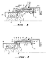
- Figs. 1, 2, 3 and 4 illustrate the lens in a retracted position, a WIDE extremity position, a TELE extremity position, and a MACRO photographing position, respectively. It can thus be easily understood from the drawings of Figs. 1-4 (and particularly Fig. 1) that the accommodation or retracted length of the lens barrel in accordance with the present invention is small.
- a stationary barrel 12 is secured to a camera body 11, preferably of a lens shutter type of zoom lens camera.
- the camera body 11 includes an outer rail 13 and an inner rail 14, respectively, which serve as a film guide.
- Inner and outer rails 13 and 14 further define a film holding plane.
- front and rear lens groups 15 and 16, respectively can be retracted to, and accommodated within, a position which is very close to the film holding plane.
- annular members such as cam ring 22 are relatively small, and, accordingly, the accommodation length of the camera can be decreased.
- a female helicoid ring 18 having inner peripheral helicoid teeth or threads 18a is secured to, and inside of, stationary barrel 12 by set screws 19.
- the female helicoid ring 18 is screw/ threadably engaged by a male helicoid ring 20 having outer peripheral helicoid teeth or threads 20a.
- Cam ring 22 is secured to male helicoid ring 20 by set screws 21, as illustrated in Fig. 5.
- a gear 20b is formed on the outer periphery of male helicoid ring 20; the gear has threads or teeth, each of which extends parallel to the optical axis, as illustrated in Fig. 5.
- Gear 20b extends at the same angle of inclination as the lead angle of helicoid teeth 20a of male helicoid ring 20, i.e., it is parallel to the direction of each of the teeth or threads 20a, as shown in Figure 5.
- Cam ring 22 is rotated in both forward and reverse directions by a driving motor, described in detail hereinafter, through a pinion which meshes with gear 20b, so that when the male helicoid ring 20 is rotated, cam ring 22 is moved in the optical axis direction in accordance with the lead angle of helicoid teeth 20a, all while the cam ring is rotating.
- Lens guide ring 24 is fitted into the inner periphery of cam ring 22 so as to move together with cam ring 22 along the optical axis direction, and so that it will rotate relative to cam ring 22.
- Lens guide ring 24 includes a linear movement guide plate 26 which is secured to the rear end of the lens guide ring 24 by set screws 25.
- Linear movement guide plate 26 includes at least one outer projection which are each engaged in a respective lens guide ring guide groove 27 formed on the interior surface of stationary barrel 12.
- Each guide groove 27 is provided in the form of a straight groove, which extends along (i.e., parallel to) the optical axis direction in the embodiment which is shown in the figures.
- An annular groove 28 is provided between the linear movement guide plate 26 and the rear end of lens guide ring 24; an inner flange 29 on the rear end of cam ring 22 is relatively rotatably fitted within annular groove 28, so that lens guide ring 24 can move along the optical axis direction together with movement of cam ring 22.
- Guide ring 24 cannot, however, rotate, due to the presence of guide groove(s) 27, which engages plate 26 to prevent rotation.
- Cam ring 22 can, of course, rotate relative to (and about) lens guide ring 24.
- Front and rear lens groups 15 and 16 are secured to front lens group frame 30 and rear lens group frame 31, respectively, which are both located inside the lens guide ring 24.
- Front lens group frame 30 is connected to helicoid ring 33, which is itself secured to shutter block 32.
- the shutter block is secured to a front lens group moving frame 34, which is provided along its outer periphery with at least three guide pins 35.
- Rear lens group frame 31 is provided along its outer periphery with at least three guide pins 36.
- the guide pins are shown at the same axial positions, thereby making it possible to show only one such pin; Figures 2 and 4, however, illustrate the pins at axially spaced positions (as does, e.g., Fig. 5).
- Shutter block 32 rotates driving pin 32a over an angular displacement corresponding to an object distance which is detected by an object distance measuring device (not illustrated) in order to rotate the front lens group frame 30, which is associated with driving pin 32a, via pin 30a. In this fashion, front lens group frame 30 is moved along the optical axis direction in accordance with movement of the helicoid in order to effect focusing, in a well-known fashion. Shutter block 32 also operates shutter blades 32b in accordance with a signal representing the brightness of an object which has been detected.
- a cylindrical lens cover 38 is provided which is integral with front lens group moving frame 34, and a decorative cylinder 39 is provided which covers the outer peripheries of lens guide ring 24 and cam ring 22, which are adapted to respectively project from the outer shell lla of the camera body.
- Cam ring 22 is provided with a front lens group cam groove 41 and a rear lens group cam groove 42 within which guide pins 35 and 36, respectively, are fitted.
- Lens guide ring 24 is provided with lens guide grooves 43 and 44 which, respectively, correspond to the front lens group cam groove 41 and the rear lens group cam groove 42.
- lens guide grooves 43 and 44 are straight grooves which extend in the direction of the optical axis.
- Guide pin 35 extends through both the front lens group cam groove 41 and the lens guide groove 43
- guide pin 36 extends through both the rear lens group cam groove 42 and the lens guide groove 44.
- the profiles of front lens group cam groove 41, lens guide groove 43, and rear lens group cam groove 42, as well as lens guide groove 44, are determined such that movable lenses or lens groups 15 and 16 are moved along a predetermined axial track in accordance with the axial movement of cam ring 22 and lens guide ring 24 effected by rotation of the male helicoid ring 20, and by relative rotation of cam ring 22 with respect to lens guide ring 24.
- the zoom lens as constructed operates as detailed hereinafter.
- male helicoid ring 20 When male helicoid ring 20 is rotated in forward and reverse directions, the male helicoid ring 20 will move along the optical axis direction while rotating, in accordance with the lead angle of helicoid teeth 20a, since the female helicoid ring 18 which is engaged by the male helicoid ring 20 is secured to stationary barrel 12.
- cam ring 22 which is secured to male helicoid ring 20, is rotated together with the male helicoid ring 20 and will be moved along the optical axis direction in accordance with the lead angle of the helicoid teeth 20a.
- lens guide ring 24 which is mounted to cam ring 22 so that the two rings will rotate with respect to each other and move together along the optical axis direction, is moved along the direction of the optical axis, without rotating, in accordance/association with axial movement of cam ring 22.
- Relative rotation of cam ring 22 and lens guide ring 24 causes axial movement of moving lenses 15 and 16 in accordance with the relationship between cam groove 41 and lens guide groove 43, as well as in accordance with the relationship between cam groove 42 and lens guide groove 44.
- Lenses 15 and 16 can be moved from the accommodation position, as shown in Fig. 1, to the macro-photographing position, which is illustrated in Fig. 4, as a result of the movement of cam ring 22 and lens guide ring 24.
- the accommodation length of the lens is extremely small, since the cam ring 22 and lens guide ring 24 do not protrude outwardly from the outer shell 11a of the camera body or from the cylindrical lens cover 38.
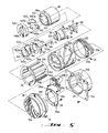
- Figs. 5-7 illustrate a barrier mechanism which can be advantageously incorporated into the zoom lens barrel referred to above, e.g.
- the barrier mechanism is notable in that its barriers are closed and opened by relative axial displacement of a cylindrical lens cover, including the barriers, and the lens guide ring 24.
- a pair of lens barriers 140 are provided on the front end of cylindrical lens cover 38. Lens barriers 140 are opened and closed in such a way that they will be closed in the accommodation position of the lens and such that they will be maintained in an open position whenever the lens is located between the accommodation position and the macro position. Although two barriers 140 are shown, one (or more than two) could also be used.
- Barriers 140 are pivoted to a surface of a flange portion 38a provided on the inner periphery of the front end of lens cover barrel 38, via respective pivot pins 141.
- Barriers 140 which are symmetrically opposed to each other, have barrier plate portions 140a which can be moved into the light path, and driving arm portions 140b which extend in opposite directions from barrier plate portions 140a, with respect to pins 141.
- Driving arm portions 140b are provided at their ends with pins 142 which extend rearwardly, along the optical axis direction, through the inner space, i.e., opening, in flange portion 38a.
- a circular disk-like intermediate ring 143 and a circular disk-like driving ring 145 for operating barriers 140 are rotatably mounted on the back of flange portion 38a.
- Intermediate ring 143 is provided along its inner periphery with grooves or notches 143a, within which pins 142 are engaged; and, along its outer periphery, with a projection 143b and intermediate engaging piece 143c, both of which extend rearwardly along the optical axis direction.
- a closing spring 144 which continuously biases lens barriers 140 to close the barriers, is provided between projection 143b and pin 145c, which itself is provided on driving ring 145.
- Driving ring 145 has an outer periphery with a driving arm 145a attached thereto which extends rearwardly along the optical axis direction.
- Driving arm 145a extends through the gap which exists between cam ring 22 and lens guide ring 24, and includes a pin 146 provided on the front end of driving arm 145a.
- Pin 146 is fitted into barrier opening and closing cam groove 24c which is formed in lens guide ring 24.
- Recess 145b is formed on the outer periphery of driving ring 145 so that the intermediate engaging piece 143c of intermediate ring 143 will be fitted into recess 145b.
- Driving ring 145 is continuously biased by an opening spring 147 which is provided between driving arm 145a and cylindrical lens cover 38 in order to open barriers 140.
- pin 146 of driving ring 145 is brought into abutment with barrier opening and closing cam groove 24c by the rotational spring force of opening spring 147.
- Intermediate engaging piece 143c of intermediate ring 143 is brought into contact with the inner wall of recess 145b of driving ring 145 under the rotational biasing force of closing spring 144; in this fashion, intermediate ring 143 rotates together with driving ring 145.
- a barrier cover 148 which covers lens barriers 140 and which includes a photographing opening 148a, is attached to the front end of lens cover barrel 38.
- pin 146 rides on an inclined portion (i.e., a barrier opening and closing drive portion) 24d of the barrier opening and closing cam groove 24c, when the zoom lens is positioned in the accommodation position illustrated in Fig. 6A.
- driving ring 145 is rotated against the force of opening spring 147 so as to close barriers 140.
- intermediate ring 143 rotates in the closing direction, together with driving ring 145, so as to rotate barriers 140 so that barrier plate portions 140a will close the light path (see Figs. 6A and 7A).
- cam ring 22 When motor 270 rotates, cam ring 22 also rotates and moves along the optical axis direction, as noted above, so that the front lens group moving frame 34 will move forward (with lens cover 38) relative to lens guide ring 24. Since lens cover 38, the driven or intermediate ring 143, and driving ring 145 move forward together with front lens group moving frame 34, pin 146 will move towards the portion of the barrier opening and closing cam groove 24c that extends, parallel to the optical axis, from the inclined portion 24d of the groove 24c. As a result, driving ring 145 is rotated in the barrier opening direction under the rotational biasing force of opening spring 147 so as to rotate the intermediate ring 143 in the same direction, thereby rotating barriers 140 so as to open them (see Figs.
- intermediate ring 143 is positioned between barriers 140 and driving ring 145, and closing spring 144 is positioned between intermediate ring 143 and driving ring 145 to bias the driven intermediate ring 143 towards the barrier closing direction with respect to the driving ring, so that some play (i.e., space) will be provided between the intermediate engaging piece 143c, which functionally connects intermediate ring 143 and driving ring 145, and recess 145b.
- intermediate ring 143 is rotated in the same direction, maintaining abutment of the intermediate engaging piece 143c with one of the inner walls of recess 145b, all under the biasing spring force of closing spring 144. In this fashion, barriers 140 can be rotated into the closed position. When opposed edges of the barrier plate portions 140a of barriers 140 come into contact with each other to stop rotation of barriers 140, intermediate ring 143 will stop rotating.
- driving ring 145 continues rotating further in the closing direction, thus tensing opening spring 144, since the aforementioned play does exist between recess 145b and intermediate engaging piece 143c (due to their relative sizes).
- the further or excess rotation of driving ring 145 absorbs (i.e., compensates for) possible dimensional or tolerance type errors which arise during manufacturing and assembly of components, in order to completely close barriers 140.
Landscapes
- Physics & Mathematics (AREA)
- General Physics & Mathematics (AREA)
- Optics & Photonics (AREA)
- Engineering & Computer Science (AREA)
- General Engineering & Computer Science (AREA)
- Lens Barrels (AREA)
- Non-Silver Salt Photosensitive Materials And Non-Silver Salt Photography (AREA)
- Camera Bodies And Camera Details Or Accessories (AREA)
- Structure Of Printed Boards (AREA)
- Non-Metallic Protective Coatings For Printed Circuits (AREA)
- Instruments For Viewing The Inside Of Hollow Bodies (AREA)
- Structure And Mechanism Of Cameras (AREA)
- Blocking Light For Cameras (AREA)
- Glass Compositions (AREA)
- Transforming Light Signals Into Electric Signals (AREA)
- Mounting And Adjusting Of Optical Elements (AREA)
- Automatic Focus Adjustment (AREA)
- Lasers (AREA)
Claims (3)
- Varioobjektiv mit einer Linsenabdeckung,gekennzeichnet durcheinem an einem Kameragehäuse (11) mit einer optischen Achse befestigbaren feststehenden Tubus (12),einem an dem feststehenden Tubus (12) gelagerten drehbaren Nockenring (22),mindestens einer bewegbaren vorderen Linsengruppe (15) und einer bewegbaren hinteren Linsengruppe (16), die an dem Nockenring (22) derart in Richtung der optischen Achse entlang einer vorbestimmten Bahn entsprechend seiner Drehung bewegbar gelagert sind, daß sie Mittel zum Ändern der Brennweite der Linsengruppen (15, 16) in einem Variobildaufnahmebereich sind, und die zwischen einer Ruheposition, in der die bewegbaren Linsengruppen (15, 16) vollständig zurückgezogen sind, und einer Bildaufnahmeposition bewegbar sind, in der ein Bild aufgenommen werden soll,und mit einer zusammen mit den Linsengruppen (15, 16) entlang der Richtung der optischen Achse bewegbaren zylindrischen Objektivabdeckung (38),bei dem die Linsenabdeckung Abdeckelemente (140) in der Objektivabdeckung (38), die geeignet sind, eine Bildaufnahmeöffnung vor den bewegbaren Linsengruppen (15, 16) zu öffnen und zu schließen, und einen Mechanismus (145, 146) zum Öffnen und Schließen der Abdeckelemente hat, der in der Objektivabdeckung (38) angeordnet ist und Mittel zum Öffnen und Schließen der Sperrelemente (140) abhängig von der Bewegung der Objektivabdeckung (38) hat,einen Linsenführungsring (24), der zusammen mit dem Nockenring (22) in Richtung der optischen Achse bewegbar angeordnet ist, wobei der Nockenring (22) und der Linsenführungsring (24) abhängig von der Axialbewegung des Nockenrings (22) derart relativ zueinander drehbar angeordnet sind, daß die vordere und die hintere Linsengruppe bewegt werden,einen Antriebsring (145) mit einem Antriebsarm (145a),eine Nockenbahn (24c) an dem Linsenführungsring (24) mit einem schrägen Bereich (24d) zum Betätigen des Antriebsrings (145) mittels des mit dem schrägen Bereich (24d) gekoppelten Antriebsarm (145a) derart, daß die Abdeckelemente bewegt werden,und durch ein Vorspannen des Antriebsrings (145) derart, daß die Abdeckelemente geöffnet bleiben, wenn der Antriebsring (145) nicht von dem schrägen Bereich betätigt wird.
- Varioobjektiv nach Anspruch 1, bei dem die Abdeckelemente zwei Abdeckelemente (140) sind, die an der Objektivabdeckung (38) jeweils mit einem Drehlagerstift (141) schwenkbar befestigt sind, welcher an einer zur optischen Achse rechtwinkligen Fläche der Objektivabdeckung (38) angeordnet ist.
- Varioobjektiv nach Anspruch 2, bei dem der Antriebsring (145) in einer zur optischen Achse rechtwinkligen Ebene drehbar angeordnet ist, um die zwei Abdeckelemente (140) zu öffnen und zu schließen, und daß der Antriebsarm mit dem schrägen Bereich mittels eines Verbindungselementes (146) in Eingriff steht, das abhängig von der Relativbewegung der Objektivabdeckung (38) und des Linsenführungsrings (24) entlang der Richtung der optischen Achse den Antriebsring (145) dreht.
Applications Claiming Priority (37)
| Application Number | Priority Date | Filing Date | Title |
|---|---|---|---|
| JP13701988A JP2691562B2 (ja) | 1988-06-03 | 1988-06-03 | レンズ鏡筒 |
| JP13701988 | 1988-06-03 | ||
| JP137019/88 | 1988-06-03 | ||
| JP8359388 | 1988-06-24 | ||
| JP8359488 | 1988-06-24 | ||
| JP1988083593U JPH0618325Y2 (ja) | 1988-06-24 | 1988-06-24 | ズームレンズ鏡筒 |
| JP83593/88 | 1988-06-24 | ||
| JP83592/88 | 1988-06-24 | ||
| JP83595/88 | 1988-06-24 | ||
| JP8359488U JPH0645923Y2 (ja) | 1988-06-24 | 1988-06-24 | レンズシャッタ式ズームレンズカメラの近距離補正光学素子の作動機構 |
| JP1988083592U JPH0618324Y2 (ja) | 1988-06-24 | 1988-06-24 | マクロ付きズームレンズ鏡筒 |
| JP83594/88 | 1988-06-24 | ||
| JP8359588 | 1988-06-24 | ||
| JP1988083595U JPH0618326Y2 (ja) | 1988-06-24 | 1988-06-24 | ズームレンズ鏡筒 |
| JP8359288 | 1988-06-24 | ||
| JP84735/88 | 1988-06-27 | ||
| JP84733/88 | 1988-06-27 | ||
| JP8473688 | 1988-06-27 | ||
| JP1988084735U JPH0542424Y2 (de) | 1988-06-27 | 1988-06-27 | |
| JP1988084736U JPH0544806Y2 (de) | 1988-06-27 | 1988-06-27 | |
| JP8473588 | 1988-06-27 | ||
| JP1988084734U JPH0755546Y2 (ja) | 1988-06-27 | 1988-06-27 | バリヤ装置付ズームレンズ |
| JP8473488 | 1988-06-27 | ||
| JP8473388 | 1988-06-27 | ||
| JP84734/88 | 1988-06-27 | ||
| JP1988084733U JPH0618327Y2 (ja) | 1988-06-27 | 1988-06-27 | レンズ鏡筒 |
| JP84736/88 | 1988-06-27 | ||
| JP89557/88 | 1988-07-06 | ||
| JP1988089557U JP2572803Y2 (ja) | 1988-07-06 | 1988-07-06 | ズームレンズの駆動機構 |
| JP8955888 | 1988-07-06 | ||
| JP1988089558U JPH0727451Y2 (ja) | 1988-07-06 | 1988-07-06 | ズームレンズ鏡筒 |
| JP89558/88 | 1988-07-06 | ||
| JP8955788 | 1988-07-06 | ||
| JP9707588 | 1988-07-22 | ||
| JP97075/88 | 1988-07-22 | ||
| JP1988097075U JPH082646Y2 (ja) | 1988-07-22 | 1988-07-22 | ズームレンズ鏡筒 |
| EP89110047A EP0344806B1 (de) | 1988-06-03 | 1989-06-02 | Antrieb für ein Zoomobjektiv |
Related Parent Applications (1)
| Application Number | Title | Priority Date | Filing Date |
|---|---|---|---|
| EP89110047.1 Division | 1989-06-02 |
Publications (3)
| Publication Number | Publication Date |
|---|---|
| EP0609910A2 EP0609910A2 (de) | 1994-08-10 |
| EP0609910A3 EP0609910A3 (en) | 1994-09-21 |
| EP0609910B1 true EP0609910B1 (de) | 2000-01-12 |
Family
ID=27583380
Family Applications (5)
| Application Number | Title | Priority Date | Filing Date |
|---|---|---|---|
| EP94104979A Expired - Lifetime EP0609912B1 (de) | 1988-06-03 | 1989-06-02 | Vorrichtung zur selektiven Positionierung eines korrigierenden optischen Elements in einer Kamera |
| EP89110047A Expired - Lifetime EP0344806B1 (de) | 1988-06-03 | 1989-06-02 | Antrieb für ein Zoomobjektiv |
| EP94104972A Expired - Lifetime EP0609910B1 (de) | 1988-06-03 | 1989-06-02 | Vorrichtung zur selektiven Öffnung und Schliessung einer photographischen Öffnung einer Linsenabdeckung |
| EP94104973A Expired - Lifetime EP0609911B1 (de) | 1988-06-03 | 1989-06-02 | Zoomobjektiv |
| EP94104980A Expired - Lifetime EP0609913B1 (de) | 1988-06-03 | 1989-06-02 | Flexible Platine für gedruckte Schaltung für eine Kamera |
Family Applications Before (2)
| Application Number | Title | Priority Date | Filing Date |
|---|---|---|---|
| EP94104979A Expired - Lifetime EP0609912B1 (de) | 1988-06-03 | 1989-06-02 | Vorrichtung zur selektiven Positionierung eines korrigierenden optischen Elements in einer Kamera |
| EP89110047A Expired - Lifetime EP0344806B1 (de) | 1988-06-03 | 1989-06-02 | Antrieb für ein Zoomobjektiv |
Family Applications After (2)
| Application Number | Title | Priority Date | Filing Date |
|---|---|---|---|
| EP94104973A Expired - Lifetime EP0609911B1 (de) | 1988-06-03 | 1989-06-02 | Zoomobjektiv |
| EP94104980A Expired - Lifetime EP0609913B1 (de) | 1988-06-03 | 1989-06-02 | Flexible Platine für gedruckte Schaltung für eine Kamera |
Country Status (8)
| Country | Link |
|---|---|
| US (3) | US5144493A (de) |
| EP (5) | EP0609912B1 (de) |
| KR (1) | KR970002510B1 (de) |
| AT (5) | ATE188781T1 (de) |
| AU (4) | AU631796B2 (de) |
| CA (1) | CA1331429C (de) |
| DE (3) | DE68918756T2 (de) |
| HK (5) | HK1001572A1 (de) |
Families Citing this family (114)
| Publication number | Priority date | Publication date | Assignee | Title |
|---|---|---|---|---|
| JPH08304686A (ja) * | 1995-04-28 | 1996-11-22 | Nikon Corp | レンズ駆動装置 |
| US5678137A (en) * | 1978-11-29 | 1997-10-14 | Nikon Corporation | Camera with annular light shielding member around axially moving lens housing |
| DE8718028U1 (de) | 1986-05-12 | 1992-10-15 | Asahi Kogaku Kogyo K.K., Tokio/Tokyo | Zentralverschlusskamera mit varioobjektiv |
| US5231449A (en) * | 1988-06-03 | 1993-07-27 | Asahi Kogaku Kogyo Kabushiki Kaisha | Zoom lens barrel and camera incorporating such barrel |
| CA1331429C (en) * | 1988-06-03 | 1994-08-16 | Hiroshi Nomura | Zoom lens barrel and camera incorporating such barrel |
| GB2229016B (en) * | 1989-03-09 | 1993-07-07 | Asahi Optical Co Ltd | Cam ring of lens barrel and method for manufacturing the same |
| GB2261303B (en) * | 1989-03-31 | 1993-09-15 | Asahi Optical Co Ltd | Zooming adjustment of a zoom lens |
| FR2653902B1 (de) * | 1989-10-27 | 1994-03-11 | Asahi Kogaku Kogyo Kk | |
| US5172149A (en) * | 1990-05-23 | 1992-12-15 | Victor Company Of Japan, Ltd. | Drive apparatus and drive control apparatus for optical system of camera |
| JPH04125607A (ja) * | 1990-09-18 | 1992-04-27 | Canon Inc | 光学機器 |
| US5576893A (en) * | 1990-11-20 | 1996-11-19 | Canon Kabushiki Kaisha | Zoom lens barrel |
| EP0522681B1 (de) * | 1991-07-08 | 1996-10-30 | Chinon Kabushiki Kaisha | Zoomobjektivtubus einer Zoomobjektivkamera |
| JP3201418B2 (ja) * | 1991-07-30 | 2001-08-20 | 株式会社ニコン | 焦点可変装置 |
| JP3199796B2 (ja) * | 1991-09-17 | 2001-08-20 | 旭光学工業株式会社 | カメラの測光レンズ部の構成 |
| US5386740A (en) * | 1991-09-30 | 1995-02-07 | Asahi Kogaku Kogyo Kabushiki Kaisha | Rotary feed mechanism |
| US5381272A (en) * | 1992-01-27 | 1995-01-10 | Nikon Corporation | Lens barrel with improved drum arrangement |
| GB2266162B (en) * | 1992-04-17 | 1996-02-07 | Asahi Optical Co Ltd | Zoom lens barrel with focal length detector |
| DE4312490B4 (de) * | 1992-04-17 | 2005-09-08 | Pentax Corp. | Tubus für ein Varioobjektiv mit Brennweitenerfassung |
| JP3255447B2 (ja) * | 1992-04-17 | 2002-02-12 | 旭光学工業株式会社 | ズームレンズ鏡筒の調整装置 |
| JPH0584908U (ja) * | 1992-04-17 | 1993-11-16 | 旭光学工業株式会社 | ズームレンズ鏡筒の遊び除去装置 |
| GB2266157B (en) * | 1992-04-17 | 1996-01-03 | Asahi Optical Co Ltd | Electrically driven zoom lens camera |
| JPH05346527A (ja) * | 1992-06-12 | 1993-12-27 | Nikon Corp | レンズ鏡筒 |
| JP2596881Y2 (ja) * | 1992-06-23 | 1999-06-21 | 旭光学工業株式会社 | レンズ鏡筒のフレキシブル基板の装着構造 |
| JP2584208Y2 (ja) * | 1992-07-13 | 1998-10-30 | 旭光学工業株式会社 | ズームレンズ鏡筒のピント調整装置 |
| JP3276171B2 (ja) * | 1992-08-17 | 2002-04-22 | 旭光学工業株式会社 | ズームレンズ鏡筒 |
| US5689375A (en) * | 1992-10-19 | 1997-11-18 | Canon Kabushiki Kaisha | Optical apparatus |
| US5446593A (en) * | 1992-11-05 | 1995-08-29 | Asahi Kogaku Kogyo Kabushiki Kaisha | Lens advancing mechanism |
| JP3340483B2 (ja) * | 1992-12-07 | 2002-11-05 | 旭光学工業株式会社 | レンズ鏡筒のレンズ中心調整装置 |
| DE4342637B4 (de) * | 1992-12-14 | 2006-04-13 | Pentax Corp. | Kamera mit einer Vorrichtung zum Einstellen der Bildschnittweite |
| JP2575125Y2 (ja) * | 1992-12-14 | 1998-06-25 | 旭光学工業株式会社 | カメラの駆動力伝達装置 |
| DE4342638B4 (de) * | 1992-12-25 | 2005-09-22 | Pentax Corp. | Linearführungsmechanismus für einen Zoomobjektivtubus |
| JP3248968B2 (ja) * | 1993-01-13 | 2002-01-21 | 旭光学工業株式会社 | ズームレンズ鏡筒 |
| JP3367166B2 (ja) * | 1993-10-25 | 2003-01-14 | ペンタックス株式会社 | レンズ位置調整機構 |
| JP3240758B2 (ja) | 1993-07-15 | 2001-12-25 | ミノルタ株式会社 | ズームレンズ装置及びカメラ |
| SG47529A1 (en) * | 1993-08-27 | 1998-04-17 | Asahi Optical Co Ltd | Zoom lens barrel |
| US5537262A (en) * | 1993-10-19 | 1996-07-16 | Asahi Kogaku Kogyo Kabushiki Kaisha | Rotational torque setting apparatus for screw mechanism |
| US5614973A (en) * | 1993-11-30 | 1997-03-25 | Asahi Kogaku Kogyo Kabushiki Kaisha | Lens barrier mechanism |
| JP3368022B2 (ja) * | 1993-12-01 | 2003-01-20 | キヤノン株式会社 | カメラ |
| US5604638A (en) * | 1993-12-01 | 1997-02-18 | Asahi Kogaku Kogyo Kabushiki Kaisha | Anti-reflection structure for zoom lens barrel |
| JP3249002B2 (ja) * | 1993-12-03 | 2002-01-21 | 旭光学工業株式会社 | ズームレンズ鏡筒の駆動装置 |
| US5543971A (en) * | 1993-12-06 | 1996-08-06 | Asahi Kogaku Kogyo Kabushiki Kaisha | Backlash removing device for stowed lens barrel |
| JPH07159828A (ja) * | 1993-12-06 | 1995-06-23 | Asahi Optical Co Ltd | カメラのレンズ繰出装置 |
| JP2597356Y2 (ja) * | 1993-12-06 | 1999-07-05 | 旭光学工業株式会社 | ズームレンズ鏡筒の直進案内装置 |
| US5788911A (en) * | 1993-12-20 | 1998-08-04 | Asahi Kogaku Kogyo Kabushiki Kaisha | Method of manufacturing inner gear and method of manufacturing cylindrical product |
| US5689379A (en) * | 1993-12-20 | 1997-11-18 | Asahi Kogaku Kogyo Kabushiki Kaisha | Inner gear, cylindrical product with inner gear, mold for inner gear, mold for cylindrical product with inner gear, method of manufacturing inner gear, and method of manufacturing cylindrical product with inner gear |
| US5581412A (en) * | 1993-12-27 | 1996-12-03 | Asahi Kogaku Kogyo Kabushiki Kaisha | Flexible printed circuit board supporting structure of lens barrel |
| JPH085893A (ja) * | 1994-06-22 | 1996-01-12 | Nikon Corp | レンズ鏡筒 |
| JPH085894A (ja) * | 1994-06-22 | 1996-01-12 | Nikon Corp | レンズ鏡筒 |
| US5636064A (en) * | 1994-07-05 | 1997-06-03 | Asahi Kogaku Kogyo Kabushiki Kaisha | Zoom lens barrel with flat faced helicoid threading |
| JP3401335B2 (ja) * | 1994-09-29 | 2003-04-28 | ペンタックス株式会社 | 筒状成形体 |
| JP3582022B2 (ja) * | 1994-09-29 | 2004-10-27 | コニカミノルタホールディングス株式会社 | ズームレンズ鏡胴 |
| JP3435585B2 (ja) * | 1994-10-06 | 2003-08-11 | コニカ株式会社 | カメラ |
| JPH08114738A (ja) * | 1994-10-13 | 1996-05-07 | Asahi Optical Co Ltd | 回転繰出機構 |
| US6002530A (en) * | 1994-12-22 | 1999-12-14 | Canon Kabushiki Kaisha | Lens barrel and optical apparatus |
| US6002531A (en) * | 1994-12-22 | 1999-12-14 | Canon Kabushiki Kaisha | Lens barrel and optical apparatus |
| JPH08211277A (ja) * | 1995-02-06 | 1996-08-20 | Nikon Corp | ズームレンズ鏡筒、及びズームレンズ鏡筒のフランジバックの調整方法 |
| CN1069974C (zh) * | 1995-02-08 | 2001-08-22 | 佳能株式会社 | 透镜筒 |
| JPH08211435A (ja) * | 1995-02-08 | 1996-08-20 | Nikon Corp | ズーム式レンズ鏡筒を備えた沈胴式カメラ |
| JPH08220411A (ja) * | 1995-02-08 | 1996-08-30 | Nikon Corp | レンズ鏡筒 |
| JPH08321984A (ja) * | 1995-03-22 | 1996-12-03 | Sony Corp | 自動追尾撮像装置 |
| JP3462614B2 (ja) * | 1995-04-25 | 2003-11-05 | ペンタックス株式会社 | ズームレンズ鏡筒 |
| JP3586315B2 (ja) * | 1995-06-30 | 2004-11-10 | ペンタックス株式会社 | レンズ鏡筒 |
| GB2309533B (en) * | 1996-01-26 | 2000-08-09 | Asahi Optical Co Ltd | Zoom compact camera |
| US5809348A (en) * | 1996-01-26 | 1998-09-15 | Asahi Kogaku Kogyo Kabushiki Kaisha | Zoom compact camera |
| US5999748A (en) * | 1996-01-26 | 1999-12-07 | Asahi Kogaku Kogyo Kabushiki Kaisha | Camera with lens barrier apparatus |
| US5842057A (en) * | 1996-01-26 | 1998-11-24 | Asahi Kogaki Kogo Kabushiki Kaisha | Camera with lens barrier apparatus |
| US5812325A (en) * | 1996-01-26 | 1998-09-22 | Asahi Kogaku Kogyo Kabushiki Kaisha | Telescoping-type of zoom lens |
| US5884105A (en) * | 1996-01-26 | 1999-03-16 | Asahi Kogaku Kogyo Kabushiki Kaisha | Zoom compact camera |
| KR100322207B1 (ko) * | 1996-01-26 | 2002-06-26 | 마츠모토 도루 | 텔레스코프식 줌 렌즈 |
| JP3411764B2 (ja) * | 1996-02-21 | 2003-06-03 | ペンタックス株式会社 | ヘリコイドを有する合成樹脂製レンズ鏡筒の成形金型の製造方法 |
| US5790903A (en) * | 1996-08-20 | 1998-08-04 | Fuji Photo Film Co., Ltd. | Zoom lens device |
| US5926322A (en) * | 1997-08-04 | 1999-07-20 | Fuji Photo Film Co., Ltd. | Zoom lens device with zooming position detector |
| JPH1178029A (ja) * | 1997-09-04 | 1999-03-23 | Canon Inc | インクジェット記録ヘッド |
| US5958034A (en) * | 1997-09-22 | 1999-09-28 | Compaq Computer Corporation | Inductive impedance modulation of transmission lines with stub loads |
| JP3811281B2 (ja) * | 1997-12-10 | 2006-08-16 | オリンパス株式会社 | ズームレンズ鏡筒 |
| JP2000221377A (ja) * | 1999-01-28 | 2000-08-11 | Konica Corp | ズームレンズ鏡胴及びカメラ |
| US6724428B1 (en) * | 1999-08-31 | 2004-04-20 | Nucam Corporation | Shutter and lens apparatus of a digital camera with a stepless focusing function |
| JP3495663B2 (ja) * | 1999-10-27 | 2004-02-09 | ペンタックス株式会社 | ズームレンズ鏡筒 |
| JP3548471B2 (ja) * | 1999-11-15 | 2004-07-28 | ペンタックス株式会社 | ズームレンズ鏡筒の漏光防止装置 |
| JP2001215391A (ja) * | 2000-02-01 | 2001-08-10 | Asahi Optical Co Ltd | ズームレンズ鏡筒の可動フード機構 |
| JP2001281517A (ja) * | 2000-03-31 | 2001-10-10 | Fuji Photo Optical Co Ltd | レンズ鏡胴 |
| JP2001281735A (ja) | 2000-03-31 | 2001-10-10 | Fuji Photo Optical Co Ltd | バリア開閉装置 |
| US6529338B2 (en) * | 2001-01-31 | 2003-03-04 | Ping-Yim Cheung | Zoom lens assembly with focus adjustment mechanism |
| US6522481B2 (en) | 2001-03-22 | 2003-02-18 | Pentax Corporation | Cam structure for zoom lens barrel assembly |
| US6522482B2 (en) | 2001-03-22 | 2003-02-18 | Pentax Corporation | Zoom lens barrel assembly |
| JP3762653B2 (ja) | 2001-03-22 | 2006-04-05 | ペンタックス株式会社 | 多段繰出し式レンズ鏡筒 |
| JP3679724B2 (ja) * | 2001-03-22 | 2005-08-03 | ペンタックス株式会社 | ズームレンズ鏡筒 |
| JP3742562B2 (ja) | 2001-03-22 | 2006-02-08 | ペンタックス株式会社 | レンズ鏡筒のストッパ構造 |
| TW524318U (en) * | 2002-01-18 | 2003-03-11 | Nucam Cororation | Zoom lens control mechanism |
| DE10215140B4 (de) * | 2002-04-05 | 2012-12-06 | Carl Zeiss | Objektiv für eine Filmkamera |
| JP3875913B2 (ja) * | 2002-05-10 | 2007-01-31 | ペンタックス株式会社 | 光学的位置決め調整機構を持つ光学ユニット |
| KR20030089359A (ko) * | 2002-05-17 | 2003-11-21 | 삼성전기주식회사 | 줌 기능을 갖는 촬상소자 모듈 |
| US7215374B2 (en) * | 2003-01-03 | 2007-05-08 | Micron Technology, Inc. | Camera module having geared lens barrel |
| US6963455B2 (en) * | 2003-02-05 | 2005-11-08 | Pentax Corporation | Lens barrel |
| US7307798B2 (en) * | 2003-07-29 | 2007-12-11 | The Brunton Company | Multi-step locking eye cup twist up device |
| JP4280649B2 (ja) * | 2004-01-28 | 2009-06-17 | キヤノン株式会社 | レンズ鏡筒保持装置 |
| JP4474201B2 (ja) * | 2004-05-26 | 2010-06-02 | キヤノン株式会社 | レンズ鏡筒及びカメラ |
| NZ534091A (en) * | 2004-07-13 | 2007-06-29 | Fisher & Paykel Appliances Ltd | Horizontal cooking surface with rotation causing vertical motion via slots and ball slides |
| JP4722435B2 (ja) * | 2004-08-31 | 2011-07-13 | Hoya株式会社 | ズームレンズ鏡筒のカム機構 |
| GB0506358D0 (en) * | 2004-09-29 | 2005-05-04 | Nanomotion Ltd | Assembly |
| US20080211955A1 (en) * | 2004-09-29 | 2008-09-04 | Alon Avital | Camera Modules With Lens Drive Device |
| JP4208811B2 (ja) * | 2004-10-06 | 2009-01-14 | 株式会社タムロン | ロック機構付きレンズ鏡筒 |
| JP4701131B2 (ja) * | 2006-06-23 | 2011-06-15 | Hoya株式会社 | レンズ位置検出装置 |
| JP5380783B2 (ja) * | 2007-04-04 | 2014-01-08 | 株式会社リコー | レンズ鏡胴,カメラ,デジタルカメラ,携帯型情報端末装置および画像入力装置 |
| US8098446B2 (en) | 2007-05-29 | 2012-01-17 | Nikon Corporation | Lens barrel and camera |
| JP5493851B2 (ja) * | 2009-12-30 | 2014-05-14 | ソニー株式会社 | レンズ鏡筒及び撮像装置 |
| TWI431392B (zh) * | 2011-01-20 | 2014-03-21 | Asia Optical Co Inc | The camera's focus drive |
| JP6098942B2 (ja) * | 2012-07-17 | 2017-03-22 | パナソニックIpマネジメント株式会社 | レンズ鏡筒 |
| US9958140B2 (en) * | 2013-06-27 | 2018-05-01 | Leonard Henry Friedland | Military projector with relatively movable negative and positive lenses |
| US10025164B2 (en) | 2015-04-15 | 2018-07-17 | Fluke Corporation | Bayonet force booster for add-on lens |
| WO2017117066A1 (en) * | 2015-12-31 | 2017-07-06 | Werjefelt Bertil R L | Hand-held emergency vision apparatus and system |
| JP6743081B2 (ja) * | 2018-04-09 | 2020-08-19 | キヤノン株式会社 | レンズ装置及びこれを備えた光学機器 |
| JP7494009B2 (ja) * | 2020-05-22 | 2024-06-03 | キヤノン株式会社 | レンズ装置 |
| KR20220040310A (ko) | 2020-09-23 | 2022-03-30 | 삼성전자주식회사 | 카메라 모듈 및 이를 포함하는 전자 장치 |
Family Cites Families (65)
| Publication number | Priority date | Publication date | Assignee | Title |
|---|---|---|---|---|
| US3619202A (en) * | 1970-06-11 | 1971-11-09 | Polaroid Corp | Variable frame viewfinder for photographic camera |
| CA1000547A (en) * | 1972-10-11 | 1976-11-30 | Israel Nesson | Photographic exposure control mechanism |
| FR2220800A1 (de) * | 1973-03-06 | 1974-10-04 | Canon Kk | |
| US4043642A (en) * | 1973-03-06 | 1977-08-23 | Canon Kabushiki Kaisha | Zoom lens system having electrical control of moving elements |
| US3928859A (en) * | 1974-03-22 | 1975-12-23 | Honeywell Inc | Shutter-iris for automatic camera |
| JPS5525018A (en) * | 1978-08-10 | 1980-02-22 | Konishiroku Photo Ind Co Ltd | Cam device of zoom lens |
| JPS5751366Y2 (de) * | 1978-08-21 | 1982-11-09 | ||
| JPS6020089Y2 (ja) * | 1978-11-17 | 1985-06-17 | ミノルタ株式会社 | ズ−ムレンズ鏡胴 |
| JPS55106409A (en) * | 1979-02-08 | 1980-08-15 | Canon Inc | Lens barrel of zoom lens capable of taking close-up |
| JPS55133006A (en) * | 1979-04-04 | 1980-10-16 | Asahi Optical Co Ltd | Close-up photographing changeover device of zoom lens barrel |
| JPS565108U (de) * | 1979-06-25 | 1981-01-17 | ||
| JPS5680010A (en) * | 1979-12-04 | 1981-07-01 | Asahi Optical Co Ltd | Cam groove for displacement lens |
| JPS614889Y2 (de) * | 1980-01-09 | 1986-02-15 | ||
| DE3205313C2 (de) * | 1981-02-24 | 1985-05-23 | Asahi Kogaku Kogyo K.K., Tokio/Tokyo | Kameraobjektiv |
| JPS57188004A (en) * | 1981-05-14 | 1982-11-18 | Olympus Optical Co Ltd | Automatic focusing zoom lens |
| JPS5864172A (ja) * | 1981-10-14 | 1983-04-16 | 株式会社安西製作所 | 穀粒の選別方法 |
| JPS58103004U (ja) * | 1981-12-29 | 1983-07-13 | 旭光学工業株式会社 | ズ−ムレンズの近距離合焦切換装置 |
| JPS58120227A (ja) * | 1982-01-12 | 1983-07-18 | Asahi Optical Co Ltd | オ−トフオ−カスカメラ |
| JPS58188614U (ja) * | 1982-06-07 | 1983-12-15 | 旭光学工業株式会社 | レンズ繰り出し機構 |
| JPS5923309A (ja) * | 1982-07-30 | 1984-02-06 | Sony Corp | レンズの移動機構 |
| US4596454A (en) * | 1982-09-21 | 1986-06-24 | Canon Kabushiki Kaisha | Photographic lens barrel assembly |
| JPS5951309U (ja) * | 1982-09-27 | 1984-04-04 | 旭光学工業株式会社 | フロ−テイングレンズの繰り出し機構 |
| JPS5964816A (ja) * | 1982-10-05 | 1984-04-12 | Olympus Optical Co Ltd | レンズ鏡筒 |
| US4585313A (en) * | 1982-12-14 | 1986-04-29 | West Electric Company Ltd. | Lens drive device and optical lens assembly utilizing the same |
| JPS59151467A (ja) * | 1983-02-17 | 1984-08-29 | Nissan Motor Co Ltd | 縦型mosfet |
| JPS59214836A (ja) * | 1983-05-23 | 1984-12-04 | Mamiya Koki Kk | シフトレンズ用フレキシブルプリント基板 |
| JPS6042726A (ja) * | 1983-08-18 | 1985-03-07 | Canon Inc | レンズ鏡胴 |
| JPS60153015A (ja) * | 1984-01-20 | 1985-08-12 | Nippon Kogaku Kk <Nikon> | ズ−ムレンズ鏡筒 |
| JPS60162216A (ja) * | 1984-02-02 | 1985-08-24 | Konishiroku Photo Ind Co Ltd | ズ−ムレンズ鏡胴 |
| JPH067218B2 (ja) * | 1984-05-21 | 1994-01-26 | 富士写真フイルム株式会社 | オ−トフオ−カス装置 |
| DE8428377U1 (de) * | 1984-09-27 | 1984-12-13 | Fa. Carl Zeiss, 7920 Heidenheim | Zoomobjektivfassung |
| US5099263A (en) * | 1984-11-10 | 1992-03-24 | Minolta Camera Kabushiki Kaisha | Variable focal length camera |
| US4771303A (en) * | 1984-11-10 | 1988-09-13 | Minolta Camera Kabushiki Kaisha | Variable focal length camera |
| JPS61148434A (ja) * | 1984-12-22 | 1986-07-07 | Fuji Photo Film Co Ltd | 近接合焦機能を有する自動焦点装置 |
| JP2540502B2 (ja) * | 1985-05-25 | 1996-10-02 | 株式会社ニコン | 光学系保護部材を備えたカメラ |
| US4865433A (en) * | 1985-06-27 | 1989-09-12 | Canon Kabushiki Kaisha | Zoom lens incorporating diaphragm |
| FR2584190B1 (fr) * | 1985-06-28 | 1987-09-18 | Ecole Nale Super Arts Metiers | Procede et dispositif de determination en volume de la teneur en composant magnetique d'un materiau |
| JPS6279432A (ja) * | 1985-10-03 | 1987-04-11 | Konishiroku Photo Ind Co Ltd | カメラの遮光装置 |
| JPS62127513A (ja) * | 1985-11-26 | 1987-06-09 | Nippon Seiko Kk | スピンドル |
| JPH07119872B2 (ja) * | 1985-12-02 | 1995-12-20 | 旭光学工業株式会社 | ズ−ムレンズ鏡筒 |
| US5214462A (en) * | 1986-05-12 | 1993-05-25 | Asahi Kogaku Kogyo Kabushiki Kaisha | Lens shutter camera including zoom lens and barrier mechanisms |
| US5016032A (en) * | 1986-05-12 | 1991-05-14 | Asahi Kogaku Kogyo Kabushiki Kaisha | Lens shutter camera including zoom lens |
| DE8718028U1 (de) * | 1986-05-12 | 1992-10-15 | Asahi Kogaku Kogyo K.K., Tokio/Tokyo | Zentralverschlusskamera mit varioobjektiv |
| US4944030B1 (en) * | 1986-05-12 | 1993-05-25 | Asahi Optical Co Ltd | Lens shutter camera including zoom lens |
| JPS6326832A (ja) * | 1986-07-21 | 1988-02-04 | Mitsubishi Electric Corp | 光デイスク装置 |
| JPS6349740A (ja) * | 1986-08-20 | 1988-03-02 | Canon Inc | 可変焦点カメラのフレキシブルプリント基板実装構造 |
| JPH07123121B2 (ja) * | 1986-09-24 | 1995-12-25 | 松下電器産業株式会社 | プラズマ処理装置 |
| JPS6395426A (ja) * | 1986-10-11 | 1988-04-26 | Minolta Camera Co Ltd | カメラ |
| JPS63148213A (ja) * | 1986-12-12 | 1988-06-21 | Nikon Corp | レンズ直進繰出し装置 |
| US4804331A (en) * | 1986-12-27 | 1989-02-14 | Canon Kabushiki Kaisha | Device for installing printed circuit board |
| US4848884A (en) * | 1987-02-05 | 1989-07-18 | Ricoh Company, Ltd. | Variable focusing lens barrel |
| JPS63201613A (ja) * | 1987-02-18 | 1988-08-19 | Olympus Optical Co Ltd | 電装内蔵レンズ |
| JPH0782143B2 (ja) * | 1987-02-25 | 1995-09-06 | 旭光学工業株式会社 | 自動焦点カメラのマクロ撮影時のピント補正装置 |
| JPS63160520U (de) * | 1987-04-06 | 1988-10-20 | ||
| JP2630395B2 (ja) * | 1987-04-30 | 1997-07-16 | 京セラ株式会社 | ズームレンズ付沈胴式カメラ |
| US4864348A (en) * | 1987-09-03 | 1989-09-05 | Canon Kabushiki Kaisha | Structure for installing flexible printed circuit board |
| JPH01140136A (ja) * | 1987-11-27 | 1989-06-01 | Canon Inc | レンズ鏡筒 |
| US4974949B1 (en) * | 1987-12-21 | 1996-06-04 | Asahi Optical Co Ltd | Zoom lens barrel |
| JP2709932B2 (ja) * | 1988-02-03 | 1998-02-04 | 旭光学工業株式会社 | ズームレンズ駆動装置 |
| JPH0453627Y2 (de) * | 1988-03-11 | 1992-12-16 | ||
| JP2524455Y2 (ja) * | 1988-06-01 | 1997-01-29 | 旭光学工業株式会社 | ズームレンズのカム構造 |
| CA1331429C (en) * | 1988-06-03 | 1994-08-16 | Hiroshi Nomura | Zoom lens barrel and camera incorporating such barrel |
| US5029991A (en) * | 1989-04-13 | 1991-07-09 | Canon Kabushiki Kaisha | Lens barrel |
| JPH0753052Y2 (ja) * | 1989-05-22 | 1995-12-06 | 旭光学工業株式会社 | レンズのフレキシブル基板取付構造 |
| JP2508107Y2 (ja) * | 1990-06-01 | 1996-08-21 | 旭光学工業株式会社 | レンズ鏡筒 |
-
1989
- 1989-06-01 CA CA000601515A patent/CA1331429C/en not_active Expired - Fee Related
- 1989-06-02 EP EP94104979A patent/EP0609912B1/de not_active Expired - Lifetime
- 1989-06-02 EP EP89110047A patent/EP0344806B1/de not_active Expired - Lifetime
- 1989-06-02 AT AT94104972T patent/ATE188781T1/de not_active IP Right Cessation
- 1989-06-02 EP EP94104972A patent/EP0609910B1/de not_active Expired - Lifetime
- 1989-06-02 AT AT94104979T patent/ATE188554T1/de not_active IP Right Cessation
- 1989-06-02 DE DE68918756T patent/DE68918756T2/de not_active Expired - Fee Related
- 1989-06-02 US US07/361,632 patent/US5144493A/en not_active Expired - Lifetime
- 1989-06-02 EP EP94104973A patent/EP0609911B1/de not_active Expired - Lifetime
- 1989-06-02 AT AT94104980T patent/ATE173838T1/de not_active IP Right Cessation
- 1989-06-02 AT AT89110047T patent/ATE112862T1/de not_active IP Right Cessation
- 1989-06-02 EP EP94104980A patent/EP0609913B1/de not_active Expired - Lifetime
- 1989-06-02 DE DE68929078T patent/DE68929078T2/de not_active Expired - Fee Related
- 1989-06-02 DE DE68928864T patent/DE68928864T2/de not_active Expired - Fee Related
- 1989-06-02 AT AT94104973T patent/ATE184996T1/de not_active IP Right Cessation
- 1989-06-03 KR KR1019890007642A patent/KR970002510B1/ko not_active IP Right Cessation
- 1989-06-05 AU AU36023/89A patent/AU631796B2/en not_active Ceased
-
1992
- 1992-01-31 US US07/829,873 patent/US5164757A/en not_active Expired - Lifetime
- 1992-01-31 US US07/831,205 patent/US5270868A/en not_active Expired - Lifetime
-
1993
- 1993-03-08 AU AU34045/93A patent/AU645926B2/en not_active Ceased
- 1993-03-08 AU AU34044/93A patent/AU650384B2/en not_active Ceased
- 1993-03-08 AU AU34043/93A patent/AU647986B2/en not_active Ceased
-
1998
- 1998-01-20 HK HK98100505A patent/HK1001572A1/xx not_active IP Right Cessation
- 1998-05-08 HK HK98104016A patent/HK1004865A1/xx not_active IP Right Cessation
- 1998-05-08 HK HK98104018A patent/HK1004867A1/xx not_active IP Right Cessation
- 1998-05-08 HK HK98104017A patent/HK1004866A1/xx not_active IP Right Cessation
- 1998-05-08 HK HK98104015A patent/HK1004864A1/xx not_active IP Right Cessation
Also Published As
Similar Documents
| Publication | Publication Date | Title |
|---|---|---|
| EP0609910B1 (de) | Vorrichtung zur selektiven Öffnung und Schliessung einer photographischen Öffnung einer Linsenabdeckung | |
| US5488513A (en) | Zoom lens barrel | |
| EP0510379B1 (de) | Öffnungs- und Schliessmechanismus für ein Objektiv | |
| US5430516A (en) | Driving apparatus of camera | |
| US5037187A (en) | Zoom lens mount assembly | |
| US5214462A (en) | Lens shutter camera including zoom lens and barrier mechanisms | |
| US5313329A (en) | Lens hood assembly for zoom lens | |
| US5708533A (en) | Zoom lens barrel | |
| GB2230354A (en) | Camera zoom lens | |
| GB2262356A (en) | Focal point adjusting device for zoom lens | |
| GB2230107A (en) | Zoom lens barrel | |
| US5034762A (en) | Light interception device | |
| GB2281407A (en) | Zoom lens having at least two telescoping barrels | |
| US8014660B2 (en) | Retractable zoom lens having variable aperture-stop mechanism | |
| US5410432A (en) | Diaphragm mechanism of zoom lens barrel | |
| US5689738A (en) | Camera having back focus adjusting apparatus | |
| JPH0720536A (ja) | レンズ鏡筒 | |
| US4948227A (en) | Apparatus for operatively connecting cam ring and associated member actuated thereby | |
| JPH01306808A (ja) | レンズ鏡筒 | |
| CA1336656C (en) | Zoom lens camera incorporating correcting optical element | |
| CA1337712C (en) | Lens shutter camera including zoom lens | |
| JPH0720370A (ja) | レンズ鏡筒 | |
| JPH0618327Y2 (ja) | レンズ鏡筒 | |
| JPH0743596A (ja) | ズーム位置検出装置 | |
| CA1333016C (en) | Lens shutter camera including zoom lens |
Legal Events
| Date | Code | Title | Description |
|---|---|---|---|
| PUAI | Public reference made under article 153(3) epc to a published international application that has entered the european phase |
Free format text: ORIGINAL CODE: 0009012 |
|
| PUAL | Search report despatched |
Free format text: ORIGINAL CODE: 0009013 |
|
| AC | Divisional application: reference to earlier application |
Ref document number: 344806 Country of ref document: EP |
|
| AK | Designated contracting states |
Kind code of ref document: A2 Designated state(s): AT BE CH DE FR GB LI |
|
| AK | Designated contracting states |
Kind code of ref document: A3 Designated state(s): AT BE CH DE FR GB LI |
|
| 17P | Request for examination filed |
Effective date: 19941111 |
|
| 17Q | First examination report despatched |
Effective date: 19960905 |
|
| GRAG | Despatch of communication of intention to grant |
Free format text: ORIGINAL CODE: EPIDOS AGRA |
|
| GRAG | Despatch of communication of intention to grant |
Free format text: ORIGINAL CODE: EPIDOS AGRA |
|
| GRAH | Despatch of communication of intention to grant a patent |
Free format text: ORIGINAL CODE: EPIDOS IGRA |
|
| GRAH | Despatch of communication of intention to grant a patent |
Free format text: ORIGINAL CODE: EPIDOS IGRA |
|
| GRAA | (expected) grant |
Free format text: ORIGINAL CODE: 0009210 |
|
| AC | Divisional application: reference to earlier application |
Ref document number: 344806 Country of ref document: EP |
|
| AK | Designated contracting states |
Kind code of ref document: B1 Designated state(s): AT BE CH DE FR GB LI |
|
| REF | Corresponds to: |
Ref document number: 188781 Country of ref document: AT Date of ref document: 20000115 Kind code of ref document: T |
|
| REG | Reference to a national code |
Ref country code: CH Ref legal event code: EP |
|
| REF | Corresponds to: |
Ref document number: 68929135 Country of ref document: DE Date of ref document: 20000217 |
|
| REG | Reference to a national code |
Ref country code: CH Ref legal event code: NV Representative=s name: PATENTANWALTSBUERO FELDMANN AG |
|
| ET | Fr: translation filed | ||
| PLBE | No opposition filed within time limit |
Free format text: ORIGINAL CODE: 0009261 |
|
| STAA | Information on the status of an ep patent application or granted ep patent |
Free format text: STATUS: NO OPPOSITION FILED WITHIN TIME LIMIT |
|
| 26N | No opposition filed | ||
| REG | Reference to a national code |
Ref country code: GB Ref legal event code: IF02 |
|
| PGFP | Annual fee paid to national office [announced via postgrant information from national office to epo] |
Ref country code: DE Payment date: 20060525 Year of fee payment: 18 |
|
| PGFP | Annual fee paid to national office [announced via postgrant information from national office to epo] |
Ref country code: CH Payment date: 20060530 Year of fee payment: 18 |
|
| PGFP | Annual fee paid to national office [announced via postgrant information from national office to epo] |
Ref country code: GB Payment date: 20060531 Year of fee payment: 18 |
|
| PGFP | Annual fee paid to national office [announced via postgrant information from national office to epo] |
Ref country code: FR Payment date: 20060608 Year of fee payment: 18 |
|
| PGFP | Annual fee paid to national office [announced via postgrant information from national office to epo] |
Ref country code: AT Payment date: 20060613 Year of fee payment: 18 |
|
| PGFP | Annual fee paid to national office [announced via postgrant information from national office to epo] |
Ref country code: BE Payment date: 20060817 Year of fee payment: 18 |
|
| REG | Reference to a national code |
Ref country code: CH Ref legal event code: PFA Owner name: ASAHI KOGAKU KOGYO KABUSHIKI KAISHA Free format text: ASAHI KOGAKU KOGYO KABUSHIKI KAISHA#36-9, MAENO-CHO 2-CHOME ITABASHI-KU#TOKYO 174-8639 (JP) -TRANSFER TO- ASAHI KOGAKU KOGYO KABUSHIKI KAISHA#36-9, MAENO-CHO 2-CHOME ITABASHI-KU#TOKYO 174-8639 (JP) |
|
| BERE | Be: lapsed |
Owner name: *ASAHI KOGAKU KOGYO K.K. Effective date: 20070630 |
|
| REG | Reference to a national code |
Ref country code: CH Ref legal event code: PL |
|
| GBPC | Gb: european patent ceased through non-payment of renewal fee |
Effective date: 20070602 |
|
| PG25 | Lapsed in a contracting state [announced via postgrant information from national office to epo] |
Ref country code: AT Free format text: LAPSE BECAUSE OF NON-PAYMENT OF DUE FEES Effective date: 20070602 |
|
| PG25 | Lapsed in a contracting state [announced via postgrant information from national office to epo] |
Ref country code: BE Free format text: LAPSE BECAUSE OF NON-PAYMENT OF DUE FEES Effective date: 20070630 |
|
| REG | Reference to a national code |
Ref country code: FR Ref legal event code: ST Effective date: 20080229 |
|
| PG25 | Lapsed in a contracting state [announced via postgrant information from national office to epo] |
Ref country code: LI Free format text: LAPSE BECAUSE OF NON-PAYMENT OF DUE FEES Effective date: 20070630 Ref country code: DE Free format text: LAPSE BECAUSE OF NON-PAYMENT OF DUE FEES Effective date: 20080101 Ref country code: CH Free format text: LAPSE BECAUSE OF NON-PAYMENT OF DUE FEES Effective date: 20070630 |
|
| PG25 | Lapsed in a contracting state [announced via postgrant information from national office to epo] |
Ref country code: GB Free format text: LAPSE BECAUSE OF NON-PAYMENT OF DUE FEES Effective date: 20070602 |
|
| PG25 | Lapsed in a contracting state [announced via postgrant information from national office to epo] |
Ref country code: FR Free format text: LAPSE BECAUSE OF NON-PAYMENT OF DUE FEES Effective date: 20070702 |