EP0248527B1 - Système de réverbération numerique - Google Patents
Système de réverbération numerique Download PDFInfo
- Publication number
- EP0248527B1 EP0248527B1 EP87303803A EP87303803A EP0248527B1 EP 0248527 B1 EP0248527 B1 EP 0248527B1 EP 87303803 A EP87303803 A EP 87303803A EP 87303803 A EP87303803 A EP 87303803A EP 0248527 B1 EP0248527 B1 EP 0248527B1
- Authority
- EP
- European Patent Office
- Prior art keywords
- waveguide
- junction
- signal
- digital
- waveguides
- Prior art date
- Legal status (The legal status is an assumption and is not a legal conclusion. Google has not performed a legal analysis and makes no representation as to the accuracy of the status listed.)
- Expired - Lifetime
Links
Images


Classifications
-
- G—PHYSICS
- G06—COMPUTING; CALCULATING OR COUNTING
- G06F—ELECTRIC DIGITAL DATA PROCESSING
- G06F15/00—Digital computers in general; Data processing equipment in general
-
- G—PHYSICS
- G10—MUSICAL INSTRUMENTS; ACOUSTICS
- G10H—ELECTROPHONIC MUSICAL INSTRUMENTS; INSTRUMENTS IN WHICH THE TONES ARE GENERATED BY ELECTROMECHANICAL MEANS OR ELECTRONIC GENERATORS, OR IN WHICH THE TONES ARE SYNTHESISED FROM A DATA STORE
- G10H1/00—Details of electrophonic musical instruments
- G10H1/0091—Means for obtaining special acoustic effects
-
- G—PHYSICS
- G10—MUSICAL INSTRUMENTS; ACOUSTICS
- G10H—ELECTROPHONIC MUSICAL INSTRUMENTS; INSTRUMENTS IN WHICH THE TONES ARE GENERATED BY ELECTROMECHANICAL MEANS OR ELECTRONIC GENERATORS, OR IN WHICH THE TONES ARE SYNTHESISED FROM A DATA STORE
- G10H5/00—Instruments in which the tones are generated by means of electronic generators
- G10H5/007—Real-time simulation of G10B, G10C, G10D-type instruments using recursive or non-linear techniques, e.g. waveguide networks, recursive algorithms
-
- G—PHYSICS
- G10—MUSICAL INSTRUMENTS; ACOUSTICS
- G10H—ELECTROPHONIC MUSICAL INSTRUMENTS; INSTRUMENTS IN WHICH THE TONES ARE GENERATED BY ELECTROMECHANICAL MEANS OR ELECTRONIC GENERATORS, OR IN WHICH THE TONES ARE SYNTHESISED FROM A DATA STORE
- G10H7/00—Instruments in which the tones are synthesised from a data store, e.g. computer organs
-
- G—PHYSICS
- G10—MUSICAL INSTRUMENTS; ACOUSTICS
- G10H—ELECTROPHONIC MUSICAL INSTRUMENTS; INSTRUMENTS IN WHICH THE TONES ARE GENERATED BY ELECTROMECHANICAL MEANS OR ELECTRONIC GENERATORS, OR IN WHICH THE TONES ARE SYNTHESISED FROM A DATA STORE
- G10H2250/00—Aspects of algorithms or signal processing methods without intrinsic musical character, yet specifically adapted for or used in electrophonic musical processing
- G10H2250/315—Sound category-dependent sound synthesis processes [Gensound] for musical use; Sound category-specific synthesis-controlling parameters or control means therefor
- G10H2250/461—Gensound wind instruments, i.e. generating or synthesising the sound of a wind instrument, controlling specific features of said sound
- G10H2250/465—Reed instrument sound synthesis, controlling specific features of said sound
-
- G—PHYSICS
- G10—MUSICAL INSTRUMENTS; ACOUSTICS
- G10H—ELECTROPHONIC MUSICAL INSTRUMENTS; INSTRUMENTS IN WHICH THE TONES ARE GENERATED BY ELECTROMECHANICAL MEANS OR ELECTRONIC GENERATORS, OR IN WHICH THE TONES ARE SYNTHESISED FROM A DATA STORE
- G10H2250/00—Aspects of algorithms or signal processing methods without intrinsic musical character, yet specifically adapted for or used in electrophonic musical processing
- G10H2250/471—General musical sound synthesis principles, i.e. sound category-independent synthesis methods
- G10H2250/511—Physical modelling or real-time simulation of the acoustomechanical behaviour of acoustic musical instruments using, e.g. waveguides or looped delay lines
- G10H2250/515—Excitation circuits or excitation algorithms therefor
-
- G—PHYSICS
- G10—MUSICAL INSTRUMENTS; ACOUSTICS
- G10H—ELECTROPHONIC MUSICAL INSTRUMENTS; INSTRUMENTS IN WHICH THE TONES ARE GENERATED BY ELECTROMECHANICAL MEANS OR ELECTRONIC GENERATORS, OR IN WHICH THE TONES ARE SYNTHESISED FROM A DATA STORE
- G10H2250/00—Aspects of algorithms or signal processing methods without intrinsic musical character, yet specifically adapted for or used in electrophonic musical processing
- G10H2250/471—General musical sound synthesis principles, i.e. sound category-independent synthesis methods
- G10H2250/511—Physical modelling or real-time simulation of the acoustomechanical behaviour of acoustic musical instruments using, e.g. waveguides or looped delay lines
- G10H2250/535—Waveguide or transmission line-based models
Definitions
- This invention relates to the field of digital signal processing and particularly to signal processing useful in digital music synthesis and other applications.
- Digital music synthesis has attracted increased interest as data processors have undergone new developments which provide increased performance capabilities. Digital music synthesis has many applications such as the synthesis of stringed, reed and other instruments and such as the synthesis of reverberation.
- Digital reverberation has also been difficult to achieve. Although digital music synthesis has employed digital reverberation as a post-processing function for many years, there still remains a need to be able to simulate with digital signal processing the quality of reverberation which exists in natural listening-space environments.
- the goal of digital reverberation is to produce digital signal processing methods which simulate the effect that a good concert hall or other good "listening space" has on sound. This goal is made difficult because typical good listening spaces are inherently large-order, complex acoustical systems which cannot be precisely simulated in real-time using commonly available computing techniques.
- One example of a computationally simple model relies upon convolving unreverberated sound with exponentially decaying white noise thereby producing the heretofore best known artificial reverberation.
- the digital reverberator designs based upon quantitative physical models need to be replaced by models based upon simple computations which retain the qualitative behavior of natural listening space reverberation.
- Some basic building blocks of presently known digital reverberators include cascaded and nested allpass networks, recursive and non-recursive comb filters, tapped delay lines, and lowpass filters.
- the early reflections can be exactly matched for a fixed source and listener position using a tapped delay line, and the late reverberation can be qualitatively matched using a combination of allpass chains, comb filters, and lowpass filters.
- Using a lowpass filter in the feedback loop of a comb filter simulates air absorption and nonspecular reflection.
- US-A-4475229 illustrates a branched network of digital waveguides interconnected by junctions, provided with means for introducing losses into signals propagating in the network.
- Each waveguide includes two digital delay lines running parallel to each other for propagating signals in opposite directions.
- the network as a whole may have a circular or linear configuration.
- the present invention provides a digital reverberation system comprising: a branched network including a plurality of branches formed of digital waveguides and a plurality of junctions interconnecting the waveguides, input means for providing to the network an audio input signal to be reverberated; output means for providing at least one reverberation output signal from the network; and means for introducing losses into signals propagating in the network; wherein: each waveguide includes two digital delay lines running parallel to each other for propagating signals in opposite directions and has a first end and a second end, said first end having an input to a first of said two delay lines and an output from a second of said two delay lines and said second end having an input to the second delay line and an output from the first delay line, each waveguide having at least one of its ends connected to a junction; characterised in that at least one of the junctions has at least three waveguide ends connected to it and signals arriving at each junction from a particular waveguide end are partially transmitted to every other waveguide end connected to the junction and partially reflected back to
- the present invention is a signal processor formed using digital waveguide networks.
- the digital waveguide networks have signal scattering junctions.
- a junction connects two waveguide sections together or terminates a waveguide.
- the junctions are constructed from conventional digital components such as multipliers, adders, and delay elements. The number of multiplies and additions determines the number of signal-scattering junctions that can be implemented in the waveguide network, and the number of delays determines the total delay which can be distributed among the waveguides interconnecting the junctions in the waveguide network.
- the waveguides of the present invention include a first rail for conducting signals from stage to stage in one direction and a second rail for conducting signals from stage to stage in the opposite direction.
- the accumulated delay along the first rail is preferably substantially equal to the accumulated delay along the second rail so that the waveguide is balanced.
- the first rail is connected to the second rail at junctions so that signals conducted by one rail are also conducted in part by the other rail.
- Lossless waveguides used in the present invention are bi-directional delay lines which sometimes include embedded allpass filters. Losses are introduced as pure attenuation or lowpass filtering in one or both directions.
- FIG. 1 depicts a simple closed waveguide network, suitable for use in a reverberation system according to the invention.
- FIG. 2 depicts a 3-port waveguide network.
- FIG. 3 depicts a junction of two waveguides.
- FIG. 4 depicts a cascade waveguide network suitable for the present invention.
- FIG. 5 depicts one embodiment of a cascade waveguide network section.
- FIG. 6 depicts another embodiment of a cascade waveguide network section.
- FIG. 7 depicts a third embodiment of a cascade waveguide network section.
- FIG. 8 depicts a pipelined embodiment of a waveguide filter.
- FIG. 9 depicts a travelling pressure wave at a general point within a waveguide section.
- FIG. 10 depicts a normalized-waveguide digital filter.
- FIG. 11 depicts a wave-normalized-waveguide junction.
- FIG. 12 depicts a transformer junction
- FIG. 13 depicts transformer-coupled waveguide junction.
- FIG. 14 depicts a non-linear junction, controlled by a control variable, and connected through a plurality of ports to a plurality of waveguides.
- FIG. 15 depicts a waveguide reverberator.
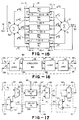
- FIG. 16 depicts a typical waveguide employed in the FIG. 15 reverberator.
- FIG. 17 depicts details of the FIG. 16 waveguide.
- a network 10 is a closed interconnection of bi-directional signal paths 11.
- the signal paths 11 are called branches or waveguides, designated 11-1, 11-2, 11-3, 11-4, and 11-5 and the interconnection points are called nodes or junctions, designated 12-1, 12-2, 12-3, and 12-4.
- An example of a simple network is shown in FIG. 1 where each signal path is bi-directional, meaning that in each waveguide there is a signal propagating in one direction and an independent signal propagating in the other direction. When a signal reaches a junction, one component is partially reflected back along the same waveguide, and other components are partially transmitted into the other waveguides connected to the junction.
- the relative strengths of the components of the transmitted or "scattered" signals at each junction are determined by the relative characteristic impedances of the waveguides at the junction. In FIG. 1, the waveguides 11 intersect at the junctions 12.
- a lossless waveguide such as each of the waveguides in FIG. 1, is defined specifically as a lossless bi-directional signal branch.
- each branch or waveguide 11 in a waveguide network 10 is merely a bi-directional delay line. The only computations in the network take place at the branch intersection points (nodes or junctions).
- a lossless waveguide branch may contain a chain of cascaded allpass filters. For practical reverberator and other designs, losses are introduced in the form of factors less than 1 and/or low pass filters with a frequency response strictly bounded above by 1 in magnitude.
- Such a structure is suitable, for example, for providing stereo reverberation of a single channel of sound. Note, however, that really in FIG. 2 there are three inputs(15, 16-2) and three out-puts(15, 16-1, 16-2) because in an N-port, each waveguide connected to the network provides both an input and an output since each waveguide is bi-directional.
- An N-port network 14 of FIG. 2 is lossless if at any time instant, the energy lost through the outputs, equals the total energy supplied through the inputs, plus the total stored energy.
- a lossless digital filter is obtained from a lossless N-port by using every port as both an input and an output. This filter is the general multi-input, multi-output allpass filter.
- An N-port network 14 is linear if superposition holds. Superposition holds when the output in response to the sum of two input signals equals the sum of the outputs in response to each individual input signal.
- a network is linear if every N-port derived from it is linear. Only linear networks can be restricted to a large and well-understood class of energy conserving systems.
- the series flow-junction is equivalent to the parallel pressure-junction.
- the series pressure-junction or the parallel flow-junction can be found by use of duality.
- the basic waveguide chain 25 is shown in FIG.4.
- the junction 26-i typically utilizes multipliers (M) 8 and adders(+) 7 to form the junction.
- the multipliers 8-1, 8-2, 8-3 and 8-4 multiply by the factors [1+k(i)], [-k i (t)], [1-k i (t)], and [k i (t)], respectively.
- An alternative junction implementation 26′-i of FIG. 13 requires only one multiply.
- the junction 26-2 in FIG. 4 corresponds, for example, to the junction 12 in FIG. 3.
- the delays 27-1 and 27-2 in FIG. 4 correspond to the branches 15 and 16, respectively, in FIG. 3.
- the Kelly-Lochbaum junctions 26-i and one-multiply junction 26′-i may be used for junction 26.
- the two-multiply lattice (not shown) and normalized ladder (FIG. 11) scattering junctions can be employed.
- the waveguide 25 employs delays 27 between each scattering junction 26 along both the top and bottom signal paths, unlike conventional ladder and lattice filters. Note that the junction 26-i of FIG. 4 employs four multipliers and two adds while junction 26′-i of FIG. 13 employs one multiply and three adds.
- junction 26 Reduction of junction 26 to other forms is merely a matter of pushing delays 27 along the top rail around to the bottom rail, so that each bottom-rail delay becomes 2T seconds (Z -2T ) instead of T seconds Z -T .
- each bottom-rail delay becomes 2T seconds (Z -2T ) instead of T seconds Z -T .
- Such an operation is possible because of the termination at the right by an infinite (or zero) characteristic impedance 6 in FIG. 4.
- pushing a delay through a multiply results in a corresponding time advance of the multiplier coefficient.
- any waveguide can be built from sections such as shown in FIG. 5.
- FIG. 8 By alternately choosing the structure of FIG. 6 and 7, the structure of FIG. 8 is obtained.
- This structure has some advantages worth considering: (1) it consolidates delays to length 2T as do conventional lattice/ladder structures, (2) it does not require a termination by an infinite characteristic impedance, allowing it to be extended to networks of arbitrary topology (e.g., multiport branching, intersection, and looping), and (3) there is no long delay-free signal path along the upper rail as in conventional structures - a pipeline segment is only two sections long.
- This structure termed the 'half-rate waveguide filter", appears to have better overall characteristics than any other digital filter structure for many applications.
- Advantage (2) makes it especially valuable for modeling physical systems.
- the instantaneous power in a waveguide containing instantaneous pressure P and flow U is defined as the product of pressure and flow as follows:
- the N-way junction is lossless; no net power, active or reactive, flows into or away from the junction.
- This normalization strategy has the property that the time-varying waveguides (as well as the junctions) conserve signal power. If the scattering junctions are implemented with one-multiply structures, then the number of multiplies per section rises to three when power is normalized. There are three additions as in the unnormalized case. In some situations (such as in the two-stage structure) it may be acceptable to normalize at fewer points; the normalizing multiplies can be pushed through the scattering junctions and combined with other normalizing multiplies, much in the same way delays were pushed through the junctions to obtain standard ladder/lattice forms. In physical modeling applications, normalizations can be limited to opposite ends of a long cascade of sections with no interior output "taps.”
- FIG. 11 illustrates the Kelly-Lochbaum junction as it applies to normalized waves.
- the multipliers 8-1, 8-2, 8-3, and 8-4 multiply by the factors [1-k 2 i (t)] 1 ⁇ 2 , -k i (t) , [1-k 2 i (t)] 1 ⁇ 2 , and k i (t), respectively.
- k i (t) cannot be factored out to obtain a one-multiply structure.
- the four-multiply structure of FIG. 11 is used in the normalized ladder filter (NLF).
- normalizing the outputs of the delay lines saves one multiply relative to the NLF which propagates normalized waves.
- duals are easier, that is, changing the propagation variable from pressure to velocity or vice versa in the i th section requires no signal normalization, and the forward and reverse reflection coefficients are unchanged. Only sign-reversal is required for the reverse path.
- the rms signal level is the same whether or not pressure or velocity is used. While appealing from a "balance of power" standpoint, normalizing all signals by their rms level can be a disadvantage.
- dynamic range can be minimized by choosing the smaller of pressure and velocity as the variable of propagation.
- a transformer joins two waveguide sections of differing characteristic impedance in such a way that signal power is preserved and no scattering occurs. It turns out that filter structures built using the transformer-coupled waveguide are equivalent to those using the normalized-wave junction described in the previous subsection, but one of the four multiplies can be traded for an addition.
- gyrator is equivalent to a transformer in cascade with a dualizer.
- a dualizer is a direct implementation of Ohm's law (to within a scale factor) where the forward path is unchanged while the reverse path is negated. On one side of the dualizer there are pressure waves, and on the other side there are velocity waves.
- Ohm's law is a gyrator in cascade with a transformer whose scale factor equals the characteristic admittance.
- the transformer-coupled junction is shown in FIG. 12.
- the multipliers 8-1 and 8-2 multiply by g i (t) and 1/g i (t) where g i (t) equals [Z i (t)/Z i-1 (t)] 1 ⁇ 2 .
- a single junction can be modulated, even in arbitrary network topologies, by inserting a transformer immediately to the left (or right) of the junction.
- the characteristic impedance is not changed over the delay-line portion of the waveguide section; instead it is changed to the new time-varying value just before (or after) it meets the junction.
- the coefficients g i (t) and g -1 i (t) in FIG. 12 are swapped (or inverted).
- the two extra multipliers 8-1 and 8-2 of FIG. 12 provide two extra multiplies per section relating to the unnormalized (one-multiply) case, thereby achieving time-varying digital filters which do not modulate stored signal energy.
- transformers enable the scattering junctions to be varied independently, without having to propagate time-varying impedance ratios throughout the waveguide network.
- the one-multiply junction 26′-i includes three adders 7-1, 7-2, and 7-3, where adder 7-3 functions to subtract the second rail signal, P - i (t), from the first rail signal, [P + i-1 (t-T)][g i (t)].
- Junction 26′-i also includes the multiplier 8 which multiplies the output from adder 7-3 by k i (t).
- FIG. 13 utilizes the junction of FIG.
- multipliers- 8-1 and 8-2 which multiply the first and second rail signals by g i (t) and 1/g i (t), respectively, where g i (t) equals [(1-k i (t))/(1+k i (t))] 1 ⁇ 2 .
- transformer-coupled waveguide of FIG. 13 and the wave-normalized waveguide are equivalent.
- One simple proof is to start with a transformer and a Kelly-Lochbaum junction, move the transformer scale factors inside the junction, combine terms, and arrive at FIG. 11.
- the practical importance of this equivalence is that the normalized ladder filter (NLF) can be implemented with only three multiplies and three additions instead of four multiplies and two additions.
- the limit cycles and overflow oscillations are easily eliminated in a waveguide structure, which precisely simulates a sampled interconnection of ideal transmissions line sections. Furthermore, the waveguide can be transformed into all well-known ladder and lattice filter structures simply by pushing delays around to the bottom rail in the special case of a cascade, reflectively terminated waveguide network. Therefore, aside from specific round-off error and time skew in the signal and filter coefficients, the samples computed in the waveguide and the samples computed in other ladder/lattice filters are identical (between junctions).
- the waveguide structure gives a precise implementation of physical wave phenomena in time-varying media. This property is valuable in its own right for simulation purposes.
- the present invention permits the delay or advance of time-varying coefficient streams in order to obtain physically correct time-varying waveguide (or acoustic tube) simulations using standard lattice/ladder structures. Also, the necessary time corrections for the traveling waves, needed to output a simulated pressure or velocity, are achieved.
- a plurality of waveguides 53 are interconnected by a non-linear junction 52.
- the junction 52 has three ports, one for each of the waveguide networks 53-1, 53-2, and 53-3.
- junction 52 can be an N-port junction interconnecting N waveguides or waveguide networks 53.
- the control variable register 51 provides one or more control variables as inputs to the junction 52.
- the single waveguide becomes a special case, single-port arrangement of FIG. 14.
- Single port examples of the FIG. 14 structure are described hereinafter in connection with reed instruments such as clarinets or saxophones.
- Multi-port examples of the FIG 14 structure are described hereinafter in connection with stringed instruments such as violins.
- a multi-port variation of the FIG. 14 structure is also described hereinafter in connection with a reverberator according to the present invention.
- Many other instruments not described in detail can also be simulated.
- flutes, organs, recorders, bassoon, oboes, all brasses, and percussion instruments can be simulated by single or multi-port, linear or non-linear junctions in combination with one or more waveguides or waveguide networks.
- One lossless reverberator according to the present invention is augmented as shown in FIG. 15 by one or more simple loss factors (typically of the form 1-2 -n ) in waveguides 30 to set the reverberation decay times to any desired values.
- the time, T60, over which the reverberation decays 60 dB is arbitrary. This decoupling of reverberation time from structure incurs no loss of generality in the present invention.
- Some of the waveguides 30 of the network are determined to give specific early reflections, while others are chosen to provide a desirable texture in the late reverberation.
- An optimality criterion for the late reverberation is to maximize homogeneity of the impulse response by making it look like exponentially decaying white noise.
- the waveguide networks of the reverberation system of the present invention allow every signal path to appear as a feedback branch around every other signal path. This connectivity richness facilitates development of dense late reverberation. Furthermore, the energy conserving properties of the waveguide networks can be maintained in the time-varying case which allows the breaking up of unwanted patterns in the late reverberation by subtly changing the reverberator in a way that does not modulate the reverberation decay profile. Finally, the explicit conservation of signal energy provides an easy way to completely suppress limit cycles and overflow oscillations.
- one typical waveguide reverberator including five waveguides (branches) formed by the waveguides 30-1, 30-2, ..., 30-5.
- the waveguides 30 are connected to junctions 31 and 32.
- the waveguides 30-1 through 30-5 have first rail inputs 33-1 through 33-5, respectively, have first rail outputs 35-1 through 35-5, respectively, have second rail inputs 36-1 through 36-5, respectively, and have second rail outputs 34-1 through 34-5, respectively.
- the first rail outputs 35-i, where i has values from 1 to 5, includes the output signals ⁇ i P + i , for i 1 through 5.
- the outputs 35-i each connect to the summing node 31.
- Summing node 31 is an adder which adds all of the ⁇ i P + i signals to form the junction pressure signal P I .
- the P I signal connects in common to each of the second rail inputs 36-1 through 36-5.
- the P I signal at terminal 20 is typically used to provide an output from the reverberator of FIG. 15.
- the input 18 is typically connected to at least one of the waveguides 30 such as waveguide 30-5.
- the outputs 34-i provide the signals ⁇ i R + i which in turn connect as inputs to the summing node 32.
- the summing node 32 sums all of the signals ⁇ i R + i to form the node signal R I at terminal 19.
- a second output is typically taken from terminal 19.
- the R I signal from summing node 32 connects in common to all of the first rail inputs 33-1 through 33-5.
- each of the waveguides 30 in FIG. 15 includes an R junction 37, a lossless waveguide 38, a loss unit 39 and a P junction 40.
- the R junction 37 includes a subtractor 41 and a multiplier 42.
- the subtractor 41 subtracts R + i from the R I signal to provide the R - i signal on line 43.
- the multiplier 42 multiplies the R + i times a gain factor, ⁇ i , to provide the signal ⁇ i R + i signal at output terminal 34-i.
- the lossless waveguide 38 includes a lossless delay 45 and a lossless delay 46.
- the delay 45 delays by a delay, N. With the signal input to the delay on line 43 equal to R - i (t), the delayed output signal on line 47 is equal to R - i (t-N). Similarly the delay 46 delays the input signal P - i (t) by N to form the delayed signal on line 44 equal by definition to P - i (t-N), which is equal to the R + i (t) signal.
- the loss unit 39 in one particular embodiment, includes a multiplier 24.
- Multiplier 24 multiplies the signal on line 47 by ⁇ to provide on the output the P + i (t) signal equal to ⁇ R - i (t-N). While the loss circuit in the form of multiplier 24 has been inserted in the line 47, the loss circuit may alternatively be placed also in any one or more of the lines 43, 44, 47 or 48.
- the P junction 40 typically includes a subtractor 21 and a multiplier 22.
- the subtractor 21 receives the P + i signal and subtracts it from the junction pressure signal P I to produce the P - i signal.
- Multiplier 22 multiplies the P + i signal by ⁇ i to form the ⁇ i P + i signal.
- the reverberator of FIGS. 15-17 consists of waveguides 30-1 through 30-5 connected together to form an arbitrary network.
- the waveguides 30-1 through 30-5 can be referred to as “branches” and their points of intersection 31 and 32 as “junctions” or “nodes”.
- Reflections are created by a mismatch between the admittances ⁇ i of the intersecting waveguides.
- a pressure wave is completely reflected with a sign reversal when it encounters an admittance which is infinitely larger than the one in which it was traveling; a pressure wave is completely reflected with no sign reversal when it encounters an admittance which is infinitely smaller than the one in which it was traveling; a pressure wave is not reflected at all (complete transmission) when it encounters an admittance which is the same as the one in which it was traveling in, the "matched-impedance" case.
- the effect of amplitude modulation of a waveguide admittance is to vary the admittance away from its original value.
- the sum of incoming scattering coefficients [ ⁇ i of Eq.(2)] must equal 2.
- ⁇ i (t) denote the time-varying branch admittances. Then from Eq.(2) and at all times.
- the objective is to vary ⁇ i (t) in a complex waveguide network such that for some waveguide admittance values ⁇ i (t).
- the easiest case is the two-junction network such as shown in FIG. 15.
- the ⁇ i (t) are identical at the two junctions.
- ⁇ i + ⁇ j c i in pairs.
- Another method for the time varying case is, at each junction, to provide one "reflection-free port" (RFP). Such a port is created when the admittance of one waveguide (that connected to the RFP) is equal to the sum of the admittances of all other waveguides meeting at that junction.
- the waveguide of the RFP has admittance 1, and it does not vary with time. We call this a "special" waveguide. Since every waveguide must connect to exactly two junctions, a special waveguide provides a RFP at two different junctions simultaneously. (A special waveguide is not very useful as a self-loop at some junction due to the next constraint.)
- a simple method for time-varying reverberation using a RFP is to pair off the time-varying waveguides so that their admittances sum to 1 in pairs. This pairing is handy because a pair is the smallest number of mutually constrained waveguides that can be arranged. When there are more than two nodes (junctions), simple complementary pairing of time-varying junctions may be difficult.
Claims (16)
- Un système de réverbération numérique comprenant :
un réseau à branches multiples, comprenant un ensemble de branches formées par des guides d'ondes numériques (11 ; 30) et un ensemble de jonctions (12 ; 26 ; 31, 32) interconnectant les guides d'ondes, des moyens d'entrée (3 ; 15 ; 18) pour appliquer au réseau un signal d'entrée audio à réverbérer ; des moyens de sortie (3 ; 16 ; 19, 20) pour fournir au moins un signal de sortie de réverbération à partir du réseau ; et des moyens (39) pour introduire des pertes dans des signaux qui se propagent dans le réseau ; dans lequel :
chaque guide d'ondes (11 ; 30) comprend deux voies de signal s'étendant parallèlement l'une à l'autre pour propager des signaux dans des directions opposées, l'une au moins des voies comprenant un élément de retard (45, 46), chaque guide d'ondes ayant une première extrémité et une seconde extrémité, la première extrémité comportant une entrée pour une première des deux voies et une sortie pour une seconde des deux voies, et la seconde extrémité comportant une entrée pour la seconde voie et une sortie pour la première voie, chaque guide d'ondes (11 ; 30) ayant l'une au moins de ses extrémités connectées à une jonction (12 ; 26 ; 31, 32) ;
caractérisé en ce que l'une au moins des jonctions (12 ; 26 ; 31, 32) est connectée à au moins trois extrémités de guides d'ondes et des signaux qui arrivent à chaque jonction (12 ; 26 ; 31, 32) à partir d'une extrémité de guide d'ondes particulière sont partiellement transmis vers chaque autre extrémité de guide d'ondes connectée à la jonction, et partiellement réfléchis en arrière vers cette extrémité de guide d'ondes particulière. - Un système de réverbération numérique selon la revendication 1, dans lequel les voies de signal consistent toutes deux en lignes à retard numériques.
- Un système de réverbération numérique selon la revendication 2, dans lequel les lignes à retard dans n'importe quel guide d'ondes particulier produisent des retards qui sont pratiquement égaux les uns aux autres.
- Un système de réverbération numérique selon la revendication 2 ou 3, dans lequel les moyens d'entrée (15 ; 18) comprennent un guide d'ondes numérique dont une extrémité est connectée à une jonction, et dans lequel le signal d'entrée est introduit à l'autre extrémité de ce guide d'ondes.
- Un système de réverbération numérique selon la revendication 2, 3 ou 4, dans lequel les moyens de sortie (16 ; 19, 20) comprennent un guide d'ondes numérique dont une extrémité est connectée à une jonction (12 ; 31, 32) du réseau, et dans lequel un signal de sortie est obtenu à son autre extrémité.
- Un système de réverbération numérique selon l'une quelconque des revendications 2 à 5, dans lequel chaque jonction comprend au moins un multiplieur (8) et un additionneur (7) (figure 4).
- Un système de réverbération numérique selon la revendication 6, dans lequel des coefficients de multiplication des multiplieurs varient au cours du temps, ce qui permet d'obtenir des caractéristiques de réverbération variant dans le temps.
- Un système de réverbération numérique selon l'une quelconque des revendications 2 à 7, dans lequel les moyens destinés à introduire des pertes ont une configuration qui procure un temps de réverbération désiré.
- Un système de réverbération numérique selon la revendication 8, dans lequel les moyens destinés à introduire des pertes introduisent un facteur de pertes de la forme 1-2-n pour au moins un signal se propageant dans le réseau, n étant un nombre entier supérieur à 0.
- Un système de réverbération numérique selon l'une quelconque des revendications 2 à 9, dans lequel au moins une jonction a des caractéristiques variant dans le temps, pour faire varier en fonction du temps I'un au moins des paramètres comprenant la transmission et la réflexion relatives vers les extrémités de guide d'ondes qui sont connectées à la jonction.
- Un système de réverbération numérique selon l'une quelconque des revendications 2 à 10, dans lequel chaque jonction comprend des multiplieurs (8) et des additionneurs (7) ayant une configuration qui permet d'interconnecter la sortie de chaque extrémité de guide d'ondes connectée à la jonction avec l'entrée de chaque extrémité de guide d'ondes connectée à la jonction, de façon à multiplier le signal provenant de chaque extrémité de guide d'ondes par un coefficient particulier et à faire la somme du signal obtenu avec des signaux multipliés provenant de chaque autre extrémité de guide d'ondes, pour appliquer ainsi un signal désiré à l'entrée de chaque extrémité de guide d'ondes qui est connectée à la jonction.
- Un système de réverbération numérique selon l'une quelconque des revendications 2 à 11, dans lequel au moins une jonction (31, 32) a une configuration telle qu'un signal provenant d'une extrémité de guide d'onde quelconque est transmis en proportions égales vers les entrées de toutes les extrémités de guides d'ondes connectées à la jonction.
- Un système de réverbération numérique selon l'une quelconque des revendications 2 à 12, comprenant des première et seconde jonctions (31, 32) et au moins trois guides d'ondes parallèles ayant chacun une valeur de retard prédéterminée, et ayant chacun une première extrémité connectée à la première jonction et une seconde extrémité connectée à la seconde jonction.
- Le système de réverbération numérique de l'une quelconque des revendications 2 à 13, dans lequel :
au moins un guide d'ondes est constitué par :
un premier élément de retard (45) dans la première ligne à retard (43, 47, 49) ;
un second élément de retard (46) dans la seconde ligne à retard (44, 48, 50) ;
des moyens (39) pour introduire une perte dans des signaux qui se propagent dans l'une au moins des lignes à retard ;
des premiers moyens soustracteurs (41) pour soustraire du signal à l'entrée de la première extrémité (33) un signal présent sur la seconde ligne à retard (44) après la sortie du second élément de retard (46), pour appliquer un signal au premier élément de retard (45) ;
des seconds moyens soustracteurs (21) pour soustraire du signal à l'entrée de la seconde extrémité (36) un signal présent sur la première ligne à retard (49) après le premier élément de retard (45), pour appliquer un signal au second élément de retard (46) ;
des premiers moyens multiplieurs de ligne à retard (24) pour multiplier un signal Pi⁺ sur la première ligne à retard après le premier élément de retard par un facteur α iRi⁺, et
dans lequel une première jonction (31) reçoit des signaux provenant de lignes à retard qui lui sont connectées et elle forme une somme PI de la façon suivante :

- Le système de réverbération numérique de l'une quelconque des revendications 2 à 14, dans lequel le réseau comprend un ensemble, i, (i > 2) de guides d'ondes connectés en parallèle entre des première et seconde jonctions, de façon que la première extrémité de chaque guide d'ondes soit connectée à la première jonction (31) et la seconde extrémité de chaque guide d'ondes soit connectée à la seconde jonction (32), ces guides d'ondes formant des signaux de sortie de première extrémité, Pi⁺, et des signaux de sortie de seconde extrémité, Ri⁺, la première jonction (31) comprenant des moyens pour faire la somme des signaux de sortie de première extrémité, Pi⁺, afin de former un signal sommé de première extrémité, Pi, et comprenant des moyens pour fournir le signal sommé de première extrémité à titre de signal de sortie de la première extrémité de chacun des guides d'ondes, et dans lequel la seconde jonction (32) comprend des moyens pour faire la somme des signaux de sortie de seconde extrémité, Ri⁺, pour former un signal de sortie sommé de seconde extrémité, RI, et elle comprend des moyens pour appliquer le signal sommé de seconde extrémité à titre de signal d'entrée à la seconde extrémité de chacun des guides d'ondes.
- Le système de réverbération numérique de l'une quelconque des revendications 2 à 15, dans lequel chaque guide d'ondes a une impédance caractéristique, et dans lequel la somme de toutes les impédances caractéristiques des guides d'ondes connectés à une jonction est une constante.
Priority Applications (1)
| Application Number | Priority Date | Filing Date | Title |
|---|---|---|---|
| EP93202895A EP0583043B1 (fr) | 1986-05-02 | 1987-04-29 | Système générateur de son musical |
Applications Claiming Priority (4)
| Application Number | Priority Date | Filing Date | Title |
|---|---|---|---|
| US85986886A | 1986-05-02 | 1986-05-02 | |
| US859868 | 1986-05-02 | ||
| US92070186A | 1986-10-17 | 1986-10-17 | |
| US920701 | 1986-10-17 |
Related Child Applications (2)
| Application Number | Title | Priority Date | Filing Date |
|---|---|---|---|
| EP93202895A Division EP0583043B1 (fr) | 1986-05-02 | 1987-04-29 | Système générateur de son musical |
| EP93202895.4 Division-Into | 1993-10-14 |
Publications (3)
| Publication Number | Publication Date |
|---|---|
| EP0248527A2 EP0248527A2 (fr) | 1987-12-09 |
| EP0248527A3 EP0248527A3 (en) | 1990-01-10 |
| EP0248527B1 true EP0248527B1 (fr) | 1995-02-01 |
Family
ID=27127548
Family Applications (2)
| Application Number | Title | Priority Date | Filing Date |
|---|---|---|---|
| EP93202895A Expired - Lifetime EP0583043B1 (fr) | 1986-05-02 | 1987-04-29 | Système générateur de son musical |
| EP87303803A Expired - Lifetime EP0248527B1 (fr) | 1986-05-02 | 1987-04-29 | Système de réverbération numerique |
Family Applications Before (1)
| Application Number | Title | Priority Date | Filing Date |
|---|---|---|---|
| EP93202895A Expired - Lifetime EP0583043B1 (fr) | 1986-05-02 | 1987-04-29 | Système générateur de son musical |
Country Status (8)
| Country | Link |
|---|---|
| EP (2) | EP0583043B1 (fr) |
| JP (6) | JP2956900B2 (fr) |
| KR (1) | KR970004084B1 (fr) |
| AU (1) | AU606864B2 (fr) |
| CA (2) | CA1335840C (fr) |
| DE (2) | DE3751032T2 (fr) |
| HK (1) | HK206596A (fr) |
| SG (1) | SG52632A1 (fr) |
Families Citing this family (82)
| Publication number | Priority date | Publication date | Assignee | Title |
|---|---|---|---|---|
| US4868869A (en) * | 1988-01-07 | 1989-09-19 | Clarity | Digital signal processor for providing timbral change in arbitrary audio signals |
| JPH01289995A (ja) * | 1988-05-17 | 1989-11-21 | Matsushita Electric Ind Co Ltd | 電子楽器 |
| JP2532613B2 (ja) * | 1988-10-18 | 1996-09-11 | 松下電器産業株式会社 | 楽音合成装置 |
| US5371317A (en) * | 1989-04-20 | 1994-12-06 | Yamaha Corporation | Musical tone synthesizing apparatus with sound hole simulation |
| JPH02281296A (ja) * | 1989-04-21 | 1990-11-16 | Yamaha Corp | 楽音合成装置 |
| JPH02281297A (ja) * | 1989-04-21 | 1990-11-16 | Yamaha Corp | 信号遅延回路および該信号遅延回路を用いた楽音合成装置 |
| US5245127A (en) * | 1989-04-21 | 1993-09-14 | Yamaha Corporation | Signal delay circuit, FIR filter and musical tone synthesizer employing the same |
| US5248844A (en) * | 1989-04-21 | 1993-09-28 | Yamaha Corporation | Waveguide type musical tone synthesizing apparatus |
| JP2504183B2 (ja) * | 1989-04-27 | 1996-06-05 | ヤマハ株式会社 | 楽音合成装置 |
| JPH0769701B2 (ja) * | 1989-05-09 | 1995-07-31 | ヤマハ株式会社 | 楽音波形信号形成装置 |
| JP2679247B2 (ja) * | 1989-05-26 | 1997-11-19 | ヤマハ株式会社 | 楽音合成方法 |
| JP2580774B2 (ja) * | 1989-05-15 | 1997-02-12 | ヤマハ株式会社 | 楽音合成装置 |
| JP2719655B2 (ja) * | 1989-07-14 | 1998-02-25 | ヤマハ株式会社 | 波形信号変換装置 |
| JP2679275B2 (ja) * | 1989-07-18 | 1997-11-19 | ヤマハ株式会社 | 楽音合成装置 |
| JP2504203B2 (ja) * | 1989-07-18 | 1996-06-05 | ヤマハ株式会社 | 楽音合成装置 |
| JPH0348898A (ja) * | 1989-07-18 | 1991-03-01 | Yamaha Corp | 信号遅延回路および該信号遅延回路を用いた楽音合成装置 |
| US5157218A (en) * | 1989-07-27 | 1992-10-20 | Yamaha Corporation | Musical tone signal forming apparatus |
| JPH0774955B2 (ja) * | 1989-07-27 | 1995-08-09 | ヤマハ株式会社 | 楽音合成装置 |
| JPH0365997A (ja) * | 1989-08-04 | 1991-03-20 | Yamaha Corp | 楽音合成装置 |
| US5187313A (en) * | 1989-08-04 | 1993-02-16 | Yamaha Corporation | Musical tone synthesizing apparatus |
| JP2722698B2 (ja) * | 1989-08-04 | 1998-03-04 | ヤマハ株式会社 | 楽音合成装置 |
| JP2977208B2 (ja) * | 1989-08-04 | 1999-11-15 | ヤマハ株式会社 | 楽音合成装置 |
| JPH0365994A (ja) * | 1989-08-04 | 1991-03-20 | Yamaha Corp | 楽音合成装置 |
| JP2679299B2 (ja) * | 1989-10-03 | 1997-11-19 | ヤマハ株式会社 | 楽音合成装置 |
| JPH03140999A (ja) * | 1989-10-27 | 1991-06-14 | Yamaha Corp | 楽音合成装置 |
| JP2722727B2 (ja) * | 1989-10-27 | 1998-03-09 | ヤマハ株式会社 | 電子楽器 |
| JPH03174196A (ja) * | 1989-10-27 | 1991-07-29 | Yamaha Corp | 楽音合成装置 |
| US5661253A (en) * | 1989-11-01 | 1997-08-26 | Yamaha Corporation | Control apparatus and electronic musical instrument using the same |
| JP2591193B2 (ja) * | 1989-11-13 | 1997-03-19 | ヤマハ株式会社 | 非線形関数発生装置およびその非線形関数発生装置を用いた楽音合成装置 |
| JP2591194B2 (ja) * | 1989-11-22 | 1997-03-19 | ヤマハ株式会社 | 非線形関数発生装置およびそれを利用した楽音合成装置 |
| US5144096A (en) * | 1989-11-13 | 1992-09-01 | Yamaha Corporation | Nonlinear function generation apparatus, and musical tone synthesis apparatus utilizing the same |
| US5403970A (en) * | 1989-11-21 | 1995-04-04 | Yamaha Corporation | Electrical musical instrument using a joystick-type control apparatus |
| JPH0772831B2 (ja) * | 1989-11-21 | 1995-08-02 | ヤマハ株式会社 | 電子楽器 |
| US5290966A (en) * | 1989-11-24 | 1994-03-01 | Yamaha Corporation | Control apparatus and electronic musical instrument using the same |
| JPH03164797A (ja) * | 1989-11-24 | 1991-07-16 | Yamaha Corp | 電子楽器 |
| JPH0792668B2 (ja) * | 1989-11-29 | 1995-10-09 | ヤマハ株式会社 | 楽音合成装置 |
| JP2591198B2 (ja) * | 1989-12-12 | 1997-03-19 | ヤマハ株式会社 | 電子楽器 |
| JPH03184095A (ja) * | 1989-12-14 | 1991-08-12 | Yamaha Corp | 電子楽器 |
| JP2508324B2 (ja) * | 1989-12-15 | 1996-06-19 | ヤマハ株式会社 | 電子楽器 |
| JPH0778679B2 (ja) * | 1989-12-18 | 1995-08-23 | ヤマハ株式会社 | 楽音波形信号形成装置 |
| EP0434086B1 (fr) * | 1989-12-22 | 1995-03-29 | Yamaha Corporation | Dispositif pour la commande de sons musicaux |
| US5241127A (en) * | 1989-12-22 | 1993-08-31 | Yamaha Corporation | Musical tone synthesizing apparatus |
| JPH03200296A (ja) * | 1989-12-28 | 1991-09-02 | Yamaha Corp | 楽音合成装置 |
| JPH087588B2 (ja) * | 1990-01-16 | 1996-01-29 | ヤマハ株式会社 | 楽音制御装置 |
| JP3008419B2 (ja) * | 1990-01-19 | 2000-02-14 | ヤマハ株式会社 | 電子楽器 |
| EP0440174B1 (fr) * | 1990-01-31 | 1996-12-11 | Yamaha Corporation | Méthode pour commander une source sonore pour un instrument de musique électronique et instrument utilisant cette méthode |
| JP2508339B2 (ja) * | 1990-02-14 | 1996-06-19 | ヤマハ株式会社 | 楽音波形信号形成装置 |
| JP2580821B2 (ja) * | 1990-02-20 | 1997-02-12 | ヤマハ株式会社 | 楽音波形信号形成装置 |
| JP2586165B2 (ja) * | 1990-02-22 | 1997-02-26 | ヤマハ株式会社 | 楽音発生装置 |
| JP2643527B2 (ja) * | 1990-03-26 | 1997-08-20 | ヤマハ株式会社 | 楽音合成装置 |
| JPH0432897A (ja) * | 1990-05-30 | 1992-02-04 | Yamaha Corp | 電子楽器の楽音制御情報入力用操作子 |
| US5179242A (en) * | 1990-06-13 | 1993-01-12 | Yamaha Corporation | Method and apparatus for controlling sound source for electronic musical instrument |
| JP2572875B2 (ja) * | 1990-06-19 | 1997-01-16 | 松下電器産業株式会社 | 楽音合成装置 |
| JPH0776877B2 (ja) * | 1990-06-20 | 1995-08-16 | ヤマハ株式会社 | 楽音合成装置 |
| JP2504298B2 (ja) * | 1990-06-20 | 1996-06-05 | ヤマハ株式会社 | 楽音合成装置 |
| US5461189A (en) * | 1990-07-06 | 1995-10-24 | Yamaha Corporation | Waveguide electronic musical instrument employing pre-performance tuning |
| JP2722795B2 (ja) * | 1990-08-08 | 1998-03-09 | ヤマハ株式会社 | 楽音合成装置 |
| JP2629418B2 (ja) * | 1990-08-09 | 1997-07-09 | ヤマハ株式会社 | 楽音合成装置 |
| JP2751598B2 (ja) * | 1990-08-09 | 1998-05-18 | ヤマハ株式会社 | 波形信号出力装置 |
| US5167179A (en) * | 1990-08-10 | 1992-12-01 | Yamaha Corporation | Electronic musical instrument for simulating a stringed instrument |
| JP2504314B2 (ja) * | 1990-09-07 | 1996-06-05 | ヤマハ株式会社 | 楽音合成装置 |
| JP2689709B2 (ja) * | 1990-09-17 | 1997-12-10 | ヤマハ株式会社 | 電子楽器 |
| JP2579049B2 (ja) * | 1990-09-21 | 1997-02-05 | 松下電器産業株式会社 | 楽音合成装置 |
| JP2861358B2 (ja) * | 1990-10-18 | 1999-02-24 | ヤマハ株式会社 | 楽音合成装置 |
| JP2751617B2 (ja) * | 1990-10-24 | 1998-05-18 | ヤマハ株式会社 | 楽音合成装置 |
| US5543580A (en) * | 1990-10-30 | 1996-08-06 | Yamaha Corporation | Tone synthesizer |
| USRE37422E1 (en) | 1990-11-20 | 2001-10-30 | Yamaha Corporation | Electronic musical instrument |
| JP2518464B2 (ja) * | 1990-11-20 | 1996-07-24 | ヤマハ株式会社 | 楽音合成装置 |
| JP2682240B2 (ja) * | 1991-01-16 | 1997-11-26 | ヤマハ株式会社 | 電子楽器 |
| JP2568759B2 (ja) * | 1991-03-07 | 1997-01-08 | 松下電器産業株式会社 | 楽音合成装置 |
| JP2576302B2 (ja) * | 1991-04-26 | 1997-01-29 | ヤマハ株式会社 | 楽音合成装置 |
| JP2738175B2 (ja) * | 1991-07-26 | 1998-04-08 | ヤマハ株式会社 | 楽音信号発生装置 |
| JP2745923B2 (ja) * | 1991-12-27 | 1998-04-28 | ヤマハ株式会社 | 電子楽器 |
| JP2565073B2 (ja) * | 1992-03-10 | 1996-12-18 | ヤマハ株式会社 | ディジタル信号処理装置 |
| JP2833403B2 (ja) * | 1993-03-26 | 1998-12-09 | ヤマハ株式会社 | 電子楽器の音源装置 |
| JP3097398B2 (ja) * | 1993-06-11 | 2000-10-10 | ヤマハ株式会社 | 残響効果付与装置 |
| JPH07319459A (ja) * | 1995-02-21 | 1995-12-08 | Yamaha Corp | 楽音制御装置および電子楽器 |
| JP2674595B2 (ja) * | 1996-06-17 | 1997-11-12 | ヤマハ株式会社 | 楽音波形信号形成装置 |
| JP3085908B2 (ja) * | 1996-07-19 | 2000-09-11 | ヤマハ株式会社 | 楽音合成装置 |
| US6000833A (en) * | 1997-01-17 | 1999-12-14 | Massachusetts Institute Of Technology | Efficient synthesis of complex, driven systems |
| JP3572892B2 (ja) * | 1997-09-24 | 2004-10-06 | ヤマハ株式会社 | マルチ音源用楽音信号生成方法、マルチ音源装置及びプログラムを記録した媒体 |
| FR2792125B1 (fr) * | 1999-04-08 | 2001-06-08 | France Telecom | Procede de simulation de la propagation non lineaire d'une onde acoustique, notamment dans un resonateur |
Family Cites Families (8)
| Publication number | Priority date | Publication date | Assignee | Title |
|---|---|---|---|---|
| DE2027303C3 (de) * | 1970-06-03 | 1975-09-04 | Siemens Ag, 1000 Berlin Und 8000 Muenchen | Filter mit frequenzabhängigen Übertragungseigenschaften für elektrische Analogsignale |
| NL7903196A (nl) * | 1979-04-24 | 1980-10-28 | Philips Nv | Inrichting voor kunstmatige nagalm. |
| US4350845A (en) * | 1979-10-10 | 1982-09-21 | Micmix Audio Products, Inc. | Reverberation apparatus |
| GB2089624B (en) * | 1980-05-29 | 1984-10-31 | Akg Akustische Kino Geraete | Artificial reverberation generator |
| AU559664B2 (en) * | 1980-07-29 | 1987-03-19 | Lawson, R.J.A. | Audio reverberation circuit |
| JPS58111096A (ja) * | 1981-12-25 | 1983-07-01 | ヤマハ株式会社 | 電子楽器のデイジタルフイルタ装置 |
| JP2544095B2 (ja) | 1984-08-17 | 1996-10-16 | ヤマハ株式会社 | 電子楽器 |
| JPS61163390A (ja) * | 1985-01-14 | 1986-07-24 | セイコーインスツルメンツ株式会社 | 電子楽器楽音発生装置 |
-
1987
- 1987-04-29 SG SG1996007061A patent/SG52632A1/en unknown
- 1987-04-29 DE DE3751032T patent/DE3751032T2/de not_active Expired - Lifetime
- 1987-04-29 EP EP93202895A patent/EP0583043B1/fr not_active Expired - Lifetime
- 1987-04-29 DE DE3752231T patent/DE3752231T2/de not_active Expired - Lifetime
- 1987-04-29 EP EP87303803A patent/EP0248527B1/fr not_active Expired - Lifetime
- 1987-04-30 CA CA000536083A patent/CA1335840C/fr not_active Expired - Lifetime
- 1987-05-01 AU AU72430/87A patent/AU606864B2/en not_active Expired
- 1987-05-02 KR KR1019870004325A patent/KR970004084B1/ko not_active IP Right Cessation
- 1987-05-02 JP JP62109618A patent/JP2956900B2/ja not_active Expired - Lifetime
-
1991
- 1991-04-10 CA CA000616041A patent/CA1316260C/fr not_active Expired - Lifetime
-
1994
- 1994-05-02 JP JP06115942A patent/JP3098911B2/ja not_active Expired - Lifetime
- 1994-05-02 JP JP6115945A patent/JPH07191685A/ja active Pending
- 1994-05-02 JP JP06115943A patent/JP3098912B2/ja not_active Expired - Lifetime
- 1994-05-02 JP JP06115941A patent/JP3098910B2/ja not_active Expired - Lifetime
- 1994-05-02 JP JP06115944A patent/JP3098913B2/ja not_active Expired - Lifetime
-
1996
- 1996-11-14 HK HK206596A patent/HK206596A/xx not_active IP Right Cessation
Also Published As
| Publication number | Publication date |
|---|---|
| JP3098910B2 (ja) | 2000-10-16 |
| DE3751032T2 (de) | 1995-09-07 |
| DE3752231T2 (de) | 1999-03-25 |
| AU606864B2 (en) | 1991-02-21 |
| CA1316260C (fr) | 1993-04-13 |
| EP0248527A2 (fr) | 1987-12-09 |
| EP0248527A3 (en) | 1990-01-10 |
| CA1335840C (fr) | 1995-06-06 |
| SG52632A1 (en) | 1998-09-28 |
| JPH07134595A (ja) | 1995-05-23 |
| JP2956900B2 (ja) | 1999-10-04 |
| EP0583043A2 (fr) | 1994-02-16 |
| DE3752231D1 (de) | 1998-12-10 |
| JP3098912B2 (ja) | 2000-10-16 |
| JPH07191685A (ja) | 1995-07-28 |
| KR870011544A (ko) | 1987-12-24 |
| KR970004084B1 (ko) | 1997-03-25 |
| JPH07134592A (ja) | 1995-05-23 |
| JP3098913B2 (ja) | 2000-10-16 |
| EP0583043A3 (fr) | 1994-12-14 |
| JP3098911B2 (ja) | 2000-10-16 |
| AU7243087A (en) | 1987-11-05 |
| EP0583043B1 (fr) | 1998-11-04 |
| DE3751032D1 (de) | 1995-03-16 |
| HK206596A (en) | 1996-11-22 |
| JPH07134594A (ja) | 1995-05-23 |
| JPH07134593A (ja) | 1995-05-23 |
| JPS6340199A (ja) | 1988-02-20 |
Similar Documents
| Publication | Publication Date | Title |
|---|---|---|
| EP0248527B1 (fr) | Système de réverbération numerique | |
| US4984276A (en) | Digital signal processing using waveguide networks | |
| US5448010A (en) | Digital signal processing using closed waveguide networks | |
| Rocchesso et al. | Circulant and elliptic feedback delay networks for artificial reverberation | |
| JPH0348897A (ja) | 楽音合成装置 | |
| JPH0778679B2 (ja) | 楽音波形信号形成装置 | |
| JPH06348290A (ja) | 残響効果付与装置 | |
| Beltrán et al. | Matlab implementation of reverberation algorithms | |
| AU631697B2 (en) | Digital signal processing using closed waveguide networks | |
| Hänninen et al. | An improved digital waveguide model of a flute with fractional delay filters | |
| Ducasse | An alternative to the traveling-wave approach for use in two-port descriptions of acoustic bores | |
| JP2738175B2 (ja) | 楽音信号発生装置 | |
| Smith et al. | Aspects of digital waveguide networks for acoustic modeling applications | |
| JP2808793B2 (ja) | 楽音合成装置 | |
| JP2580769B2 (ja) | 楽音合成装置 | |
| Kelloniemi | Room acoustics modeling with the digital waveguide mesh: boundary structures and approximation methods | |
| Välimäki et al. | An improved digital waveguide model of flute-implementation Issues | |
| JP2841847B2 (ja) | 楽音合成装置 | |
| JP3084907B2 (ja) | 残響効果付与装置 | |
| JP3404763B2 (ja) | ピッチチェンジ効果付与装置 | |
| JP3839497B2 (ja) | 楽音合成装置 | |
| Kelloniemi et al. | Hyper-dimensional digital waveguide mesh for reverberation modeling | |
| JPH02294692A (ja) | 楽音波形信号形成装置 | |
| JPH04155393A (ja) | 楽音合成装置 | |
| van Walstijn et al. | Time-Domain Simulation of Reed Woodwinds with Application to Musical Sound Synthesis |
Legal Events
| Date | Code | Title | Description |
|---|---|---|---|
| PUAI | Public reference made under article 153(3) epc to a published international application that has entered the european phase |
Free format text: ORIGINAL CODE: 0009012 |
|
| AK | Designated contracting states |
Kind code of ref document: A2 Designated state(s): DE FR GB IT NL SE |
|
| PUAL | Search report despatched |
Free format text: ORIGINAL CODE: 0009013 |
|
| AK | Designated contracting states |
Kind code of ref document: A3 Designated state(s): DE FR GB IT NL SE |
|
| 17P | Request for examination filed |
Effective date: 19900214 |
|
| D17P | Request for examination filed (deleted) | ||
| R17P | Request for examination filed (corrected) |
Effective date: 19900611 |
|
| 17Q | First examination report despatched |
Effective date: 19911223 |
|
| GRAA | (expected) grant |
Free format text: ORIGINAL CODE: 0009210 |
|
| AK | Designated contracting states |
Kind code of ref document: B1 Designated state(s): DE FR GB IT NL SE |
|
| XX | Miscellaneous (additional remarks) |
Free format text: TEILANMELDUNG 93202895.4 EINGEREICHT AM 29/04/87. |
|
| ITF | It: translation for a ep patent filed |
Owner name: JACOBACCI & PERANI S.P.A. |
|
| REF | Corresponds to: |
Ref document number: 3751032 Country of ref document: DE Date of ref document: 19950316 |
|
| ET | Fr: translation filed | ||
| PLBE | No opposition filed within time limit |
Free format text: ORIGINAL CODE: 0009261 |
|
| STAA | Information on the status of an ep patent application or granted ep patent |
Free format text: STATUS: NO OPPOSITION FILED WITHIN TIME LIMIT |
|
| 26N | No opposition filed | ||
| REG | Reference to a national code |
Ref country code: GB Ref legal event code: IF02 |
|
| PGFP | Annual fee paid to national office [announced via postgrant information from national office to epo] |
Ref country code: FR Payment date: 20060417 Year of fee payment: 20 |
|
| PGFP | Annual fee paid to national office [announced via postgrant information from national office to epo] |
Ref country code: GB Payment date: 20060424 Year of fee payment: 20 |
|
| PGFP | Annual fee paid to national office [announced via postgrant information from national office to epo] |
Ref country code: SE Payment date: 20060426 Year of fee payment: 20 |
|
| PGFP | Annual fee paid to national office [announced via postgrant information from national office to epo] |
Ref country code: IT Payment date: 20060430 Year of fee payment: 20 |
|
| PGFP | Annual fee paid to national office [announced via postgrant information from national office to epo] |
Ref country code: NL Payment date: 20060517 Year of fee payment: 20 |
|
| PGFP | Annual fee paid to national office [announced via postgrant information from national office to epo] |
Ref country code: DE Payment date: 20060531 Year of fee payment: 20 |
|
| PG25 | Lapsed in a contracting state [announced via postgrant information from national office to epo] |
Ref country code: NL Free format text: LAPSE BECAUSE OF EXPIRATION OF PROTECTION Effective date: 20070429 |
|
| REG | Reference to a national code |
Ref country code: GB Ref legal event code: PE20 |
|
| EUG | Se: european patent has lapsed | ||
| NLV7 | Nl: ceased due to reaching the maximum lifetime of a patent |
Effective date: 20070429 |
|
| PG25 | Lapsed in a contracting state [announced via postgrant information from national office to epo] |
Ref country code: GB Free format text: LAPSE BECAUSE OF EXPIRATION OF PROTECTION Effective date: 20070428 |