EP0583043A2 - Système générateur de son musical - Google Patents
Système générateur de son musical Download PDFInfo
- Publication number
- EP0583043A2 EP0583043A2 EP93202895A EP93202895A EP0583043A2 EP 0583043 A2 EP0583043 A2 EP 0583043A2 EP 93202895 A EP93202895 A EP 93202895A EP 93202895 A EP93202895 A EP 93202895A EP 0583043 A2 EP0583043 A2 EP 0583043A2
- Authority
- EP
- European Patent Office
- Prior art keywords
- signal
- junction
- wave transmission
- output
- generation system
- Prior art date
- Legal status (The legal status is an assumption and is not a legal conclusion. Google has not performed a legal analysis and makes no representation as to the accuracy of the status listed.)
- Granted
Links
Images


Classifications
-
- G—PHYSICS
- G06—COMPUTING; CALCULATING OR COUNTING
- G06F—ELECTRIC DIGITAL DATA PROCESSING
- G06F15/00—Digital computers in general; Data processing equipment in general
-
- G—PHYSICS
- G10—MUSICAL INSTRUMENTS; ACOUSTICS
- G10H—ELECTROPHONIC MUSICAL INSTRUMENTS; INSTRUMENTS IN WHICH THE TONES ARE GENERATED BY ELECTROMECHANICAL MEANS OR ELECTRONIC GENERATORS, OR IN WHICH THE TONES ARE SYNTHESISED FROM A DATA STORE
- G10H1/00—Details of electrophonic musical instruments
- G10H1/0091—Means for obtaining special acoustic effects
-
- G—PHYSICS
- G10—MUSICAL INSTRUMENTS; ACOUSTICS
- G10H—ELECTROPHONIC MUSICAL INSTRUMENTS; INSTRUMENTS IN WHICH THE TONES ARE GENERATED BY ELECTROMECHANICAL MEANS OR ELECTRONIC GENERATORS, OR IN WHICH THE TONES ARE SYNTHESISED FROM A DATA STORE
- G10H5/00—Instruments in which the tones are generated by means of electronic generators
- G10H5/007—Real-time simulation of G10B, G10C, G10D-type instruments using recursive or non-linear techniques, e.g. waveguide networks, recursive algorithms
-
- G—PHYSICS
- G10—MUSICAL INSTRUMENTS; ACOUSTICS
- G10H—ELECTROPHONIC MUSICAL INSTRUMENTS; INSTRUMENTS IN WHICH THE TONES ARE GENERATED BY ELECTROMECHANICAL MEANS OR ELECTRONIC GENERATORS, OR IN WHICH THE TONES ARE SYNTHESISED FROM A DATA STORE
- G10H7/00—Instruments in which the tones are synthesised from a data store, e.g. computer organs
-
- G—PHYSICS
- G10—MUSICAL INSTRUMENTS; ACOUSTICS
- G10H—ELECTROPHONIC MUSICAL INSTRUMENTS; INSTRUMENTS IN WHICH THE TONES ARE GENERATED BY ELECTROMECHANICAL MEANS OR ELECTRONIC GENERATORS, OR IN WHICH THE TONES ARE SYNTHESISED FROM A DATA STORE
- G10H2250/00—Aspects of algorithms or signal processing methods without intrinsic musical character, yet specifically adapted for or used in electrophonic musical processing
- G10H2250/315—Sound category-dependent sound synthesis processes [Gensound] for musical use; Sound category-specific synthesis-controlling parameters or control means therefor
- G10H2250/461—Gensound wind instruments, i.e. generating or synthesising the sound of a wind instrument, controlling specific features of said sound
- G10H2250/465—Reed instrument sound synthesis, controlling specific features of said sound
-
- G—PHYSICS
- G10—MUSICAL INSTRUMENTS; ACOUSTICS
- G10H—ELECTROPHONIC MUSICAL INSTRUMENTS; INSTRUMENTS IN WHICH THE TONES ARE GENERATED BY ELECTROMECHANICAL MEANS OR ELECTRONIC GENERATORS, OR IN WHICH THE TONES ARE SYNTHESISED FROM A DATA STORE
- G10H2250/00—Aspects of algorithms or signal processing methods without intrinsic musical character, yet specifically adapted for or used in electrophonic musical processing
- G10H2250/471—General musical sound synthesis principles, i.e. sound category-independent synthesis methods
- G10H2250/511—Physical modelling or real-time simulation of the acoustomechanical behaviour of acoustic musical instruments using, e.g. waveguides or looped delay lines
- G10H2250/515—Excitation circuits or excitation algorithms therefor
-
- G—PHYSICS
- G10—MUSICAL INSTRUMENTS; ACOUSTICS
- G10H—ELECTROPHONIC MUSICAL INSTRUMENTS; INSTRUMENTS IN WHICH THE TONES ARE GENERATED BY ELECTROMECHANICAL MEANS OR ELECTRONIC GENERATORS, OR IN WHICH THE TONES ARE SYNTHESISED FROM A DATA STORE
- G10H2250/00—Aspects of algorithms or signal processing methods without intrinsic musical character, yet specifically adapted for or used in electrophonic musical processing
- G10H2250/471—General musical sound synthesis principles, i.e. sound category-independent synthesis methods
- G10H2250/511—Physical modelling or real-time simulation of the acoustomechanical behaviour of acoustic musical instruments using, e.g. waveguides or looped delay lines
- G10H2250/535—Waveguide or transmission line-based models
Definitions
- This invention relates to the field of digital signal processing and particularly to signal processing useful in digital music synthesis and other applications.
- Digital music synthesis has attracted increased interest as data processors have undergone new developments which provide increased performance capabilities. Digital music synthesis has many applications such as the synthesis of stringed, reed and other instruments and such as the synthesis of reverberation.
- Digital reverberation has also been difficult to achieve. Although digital music synthesis has employed digital reverberation as a post-processing function for many years, there still remains a need to he able to simulate with digital signal processing the quality of reverberation which exists in natural listening-space environments.
- the goal of digital reverberation is to produce digital signal processing methods which simulate the effect that a good concert hall or other good "listening space" has on sound. This goal is made difficult because typical good listening spaces are inherently large-order, complex acoustical systems which cannot be precisely simulated in real-time using commonly available computing techniques.
- One example of a computationally simple model relies upon convolving unreverberated sound with exponentially decaying white noise thereby producing the heretofore best known artificial reverberation.
- the digital reverberator designs based upon quantitative physical models need to be replaced by models based upon simple computations which retain the qualitative behavior of natural listening space reverberation.
- Some basic building blocks of presently known digital reverberators include cascaded and nested allpass networks, recursive and non-recursive comb filters, tapped delay lines, and lowpass filters.
- the early reflections can be exactly matched for a fixed source and listener position using a tapped delay line, and the late reverberation can be qualitatively matched using a combination of allpass chains, comb filters, and lowpass filters.
- Using a lowpass filter in the feedback loop of a comb filter simulates air absorption and nonspecular reflection.
- the present invention provides a real time tone generation system characterised by: means for providing a variable control signal for initiating and thereafter controlling generation of a tone; wave transmission means for transmitting wave signals, the wave transmission means including an input and an output, a first signal path for receiving signals from the input, a second signal path for providing signals to the output, the first signal path being coupled to the second signal path, and delay means in at least one of the signal paths for delaying signals; junction means having a first input for receiving the control signal, a second input for receiving a signal from the output of the wave transmission means and an output for providing a signal as the input to the wave transmission means which is a function of at least the value of the control signal and the value of the signal received from the output of the wave transmission means so as to cause a tone signal to propagate in the wave transmission means; and tone signal extracting means for extracting a tone signal from at least one of the wave transmission means and junction means.
- An embodiment of the present invention is a signal processor formed using digital waveguide networks.
- the digital waveguide networks have signal scattering junctions.
- a junction connects two waveguide sections together or terminates a waveguide.
- the junctions are constructed from conventional digital components such as multipliers, adders, and delay elements.
- the number of multiplies and additions determines the number of signal-scattering junctions that can be implemented in the waveguide network, and the number of delays determines the total delay which can be distributed among the waveguides interconnecting the junctions in the waveguide network.
- the signal processor is typically used for synthesis of reed, string or other instruments.
- the waveguides used in the present invention may include a first rail for conducting signals from stage to stage in one direction and a second rail for conducting signals from stage to stage in the opposite direction.
- the accumulated delay along the first rail is preferably substantially equal to the accumulated delay along the second rail so that the waveguide is balanced.
- the first rail is connected to the second rail at junctions so that signals conducted by one rail are also conducted in part by the other rail.
- Lossless waveguides which may be used in the present invention are bi-directional delay lines which sometimes include embedded allpass filters. Losses are introduced as pure attenuation or lowpass filtering in one or both directions.
- the signal processor in some applications includes a non-linear junction connected to provide an input signal to the first rail of the waveguide and to receive an output signal from the second rail of the waveguide.
- a reed instrument is synthesized by a non-linear junction terminating a digital waveguide.
- a primary control variable representing mouth pressure, is input to the non-linear junction (also controlled secondarily by embouchure variables).
- the junction simulates the reed while the digital waveguide simulates the bore of the reed instrument.
- a string instrument is synthesized.
- a primary control variable representing the bow velocity
- the non-linear junction represents the bow-string interface (including secondary controls such as bow force, bow angle, bow position, and friction characteristics).
- two digital lossless waveguides are connected to the non-linear junction.
- the first waveguide represents the long string portion (from the bow to the nut) and the other waveguide simulates the short string portion (from the bow to the bridge).
- a series of waveguides can also be used to implement the body of, for example, a violin, although in such a case there is normally no direct physical interpretation of the waveguide variables.
- the reflection signal or signal coefficients introduced into the waveguides from the nonlinear junction are obtained from a table.
- the nonlinearity to be introduced into the waveguides is f(x) where x is the table address and also the incoming signal sample in the waveguide (a travelling wave sample).
- the present invention captures the musically important qualities of natural instruments in digital music synthesis with digital processing techniques employing digital waveguides which are computationally efficient and therefore capable of inexpensive real-time operation.
- FIGURES 1 to 13 show, by way of example, optional components of tone generation systems according to the invention.
- a network 10 is a closed interconnection of bi-directional signal paths 11.
- the signal paths 11 are called branches or waveguides, designated 11-1, 11-2, 11-3, 11-4, and 11-5 and the interconnection points are called nodes or junctions, designated 12-1, 12-2, 12-3, and 12-4.
- An example of a simple network is shown in FIG. 1 where each signal path is bi-directional, meaning that in each waveguide there is a signal propagating in one direction and an independent signal propagating in the other direction. When a signal reaches a junction, one component is partially reflected back along the same waveguide, and other components are partially transmitted into the other waveguides connected to the junction.
- the relative strengths of the components of the transmitted or "scattered" signals at each junction are determined by the relative characteristic impedances of the waveguides at the junction. In FIG. 1, the waveguides 11 intersect at the junctions 12.
- a lossless waveguide such as each of the waveguides in FIG. 1, is defined specifically as a lossless bi-directional signal branch.
- each branch or waveguide 11 in a waveguide network 10 is merely a bi-directional delay line. The only computations in the network take place at the branch intersection points (nodes or junctions).
- a lossless waveguide branch may contain a chain of cascaded allpass filters. For practical reverberator and other designs, losses are introduced in the form of factors less than 1 and/or low pass filters with a frequency response strictly bounded above by 1 in magnitude.
- Such a structure is suitable, for example, for providing stereo reverberation of a single channel of sound. Note, however, that really in FIG. 2 there are three inputs(15, 16-1, 16-2) and three outputs(15, 16-1, 16-2) because in an N-port, each waveguide connected to the network provides both an input and an output since each waveguide is bi-directional.
- An N-port network 14 of FIG. 2 is lossless if at any time instant, the energy lost through the outputs, equals the total energy supplied through the inputs, plus the total stored energy.
- a lossless digital filter is obtained from a lossless N-port by using every port as both an input and an output. This filter is the general multi-input, multi-output allpass filter.
- An N-port network 14 is linear if superposition holds. Superposition holds when the output in response to the sum of two input signals equals the sum of the outputs in response to each individual input signal.
- a network is linear if every N-port derived from it is linear. Only linear networks can be restricted to a large and well-understood class of energy conserving systems.
- the outgoing pressure waves are given by Eq.(1) as follows:
- the series flow-junction is equivalent to the parallel pressure-junction.
- the series pressure-junction or the parallel flow-junction can be found by use of duality.
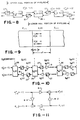
- the basic waveguide chain 25 is shown in FIG.4.
- Each junction 26-1, 26-2, ..., 26-i, ..., 26-M enclosing the symbol k i (t) denotes a scattering junction characterized by k i (t).
- the junction 26-i typically utilizes multipliers(M) 8 and adders(+) 7 to form the junction.
- the multipliers 8-1, 8-2, 8-3 and 8-4 multiply by the factors [1+k(i)], [-k i (t)], [1-k i (t)], and [k i (t)], respectively.
- An alternative junction implementation 26'-i of FIG. 13 requires only one multiply.
- junction 26-i and 27-2 in FIG. 4 correspond to the branches 15 and 16, respectively, in FIG. 3.
- the Kelly-Lochbaum junctions 26-i and one-multiply junction 26'-i may be used for junction 26.
- the two-multiply lattice (not shown) and normalized ladder (FIG. 11) scattering junctions can be employed.
- the waveguide 25 employs delays 27 between each scattering junction 26 along both the top and bottom signal paths, unlike conventional ladder and lattice filters. Note that the junction 26-i of FIG. 4 employs four multipliers and two adds while junction 26'-i of FIG. 13 employs one multiply and three adds.
- junction 26 Reduction of junction 26 to other forms is merely a matter of pushing delays 27 along the top rail around to the bottom rail, so that each bottom-rail delay becomes 2T seconds (Z -2T ) instead of T seconds Z -T .
- each bottom-rail delay becomes 2T seconds (Z -2T ) instead of T seconds Z -T .
- Such an operation is possible because of the termination at the right by an infinite (or zero) characteristic impedance 6 in FIG. 4.
- pushing a delay through a multiply results in a corresponding time advance of the multiplier coefficient.
- any waveguide can be built from sections such as shown in FIG. 5.
- FIG. 8 By alternately choosing the structure of FIG. 6 and 7, the structure of FIG. 8 is obtained.
- This structure has some advantages worth considering: (1) it consolidates delays to length 2T as do conventional lattice/ladder structures, (2) it does not require a termination by an infinite characteristic impedance, allowing it to be extended to networks of arbitrary topology (e.g., multiport branching, intersection, and looping), and (3) there is no long delay-free signal path along the upper rail as in conventional structures - a pipeline segment is only two sections long.
- This structure termed the "half-rate waveguide filter" appears to have better overall characteristics than any other digital filter structure for many applications.
- Advantage (2) makes it especially valuable for modeling physical systems.
- the instantaneous power in a waveguide containing instantaneous pressure P and flow U is defined as the product of pressure and flow as follows:
- Eqs.(5) define the right-going and left-going power, respectively.
- the time variation of the characteristic impedance does not alter the traveling pressure waves P ⁇ i .
- the power represented by a traveling pressure wave is modulated by the changing characteristic impedance as it propagates.
- the actual power becomes inversely proportional to characteristic impedance:
- This power modulation causes no difficulties in the Lyapunov theory which proves absence of limit cycles and overflow oscillations because it occurs identically in both the finite-precision and infinite-precision filters.
- it may be desirable to compensate for the power modulation so that changes in the characteristic impedances of the waveguides do not affect the power of the signals propagating within.
- Eqs.(9) become This normalization strategy has the property that the time-varying waveguides (as well as the junctions) conserve signal power. If the scattering junctions are implemented with one-multiply structures, then the number of multiplies per section rises to three when power is normalized. There are three additions as in the unnormalized case. In some situations (such as in the two-stage structure) it may be acceptable to normalize at fewer points; the normalizing multiplies can be pushed through the scattering junctions and combined with other normalizing multiplies, much in the same way delays were pushed through the junctions to obtain standard ladder/lattice forms. In physical modeling applications, normalizations can be limited to opposite ends of a long cascade of sections with no interior output "taps.”
- FIG. 11 illustrates the Kelly-Lochbaum junction as it applies to normalized waves.
- the multipliers 8-1, 8-2, 8-3, and 8-4 multiply by the factors [1-k 2 i (t)] 1 ⁇ 2 , -k i (t), [1-k 2 i (t)] 1 ⁇ 2 , and k i (t), respectively.
- k i (t) cannot be factored out to obtain a one-multiply structure.
- the four-multiply structure of FIG. 11 is used in the normalized ladder filter (NLF).
- normalizing the outputs of the delay lines saves one multiply relative to the NLF which propagates normalized waves.
- duals are easier, that is, changing the propagation variable from pressure to velocity or vice versa in the i th section requires no signal normalization, and the forward and reverse reflection coefficients are unchanged. Only sign-reversal is required for the reverse path.
- the rms signal level is the same whether or not pressure or velocity is used. While appealing from a "balance of power" standpoint, normalizing all signals by their rms level can be a disadvantage.
- dynamic range can be minimized by choosing the smaller of pressure and velocity as the variable of propagation.
- a transformer joins two waveguide sections of differing characteristic impedance in such a way that signal power is preserved and no scattering occurs. It turns out that filter structures built using the transformer-coupled waveguide are equivalent to those using the normalized-wave junction described in the previous subsection, but one of the four multiplies can be traded for an addition.
- the junction equations for a transformer can be chosen as where, from Eq. (14)
- the choice of a negative square root corresponds to a gyrator.
- the gyrator is equivalent to a transformer in cascade with a dualizer.
- a dualizer is a direct implementation of Ohm's law (to within a scale factor) where the forward path is unchanged while the reverse path is negated. On one side of the dualizer there are pressure waves, and on the other side there are velocity waves.
- Ohm's law is a gyrator in cascade with a transformer whose scale factor equals the characteristic admittance.
- the transformer-coupled junction is shown in FIG. 12.
- the multipliers 8-1 and 8-2 multiply by g i (t) and 1/g i (t) where g i (t) equals [Z i (t)/Z i-1 (t)] 1 ⁇ 2 .
- a single junction can be modulated, even in arbitrary network topologies, by inserting a transformer immediately to the left (or right) of the junction.
- the characteristic impedance is not changed over the delay-line portion of the waveguide section; instead it is changed to the new time-varying value just before (or after) it meets the junction.
- the coefficients g i (t) and g -1 i (t) in FIG. 12 are swapped (or inverted).
- the two extra multipliers 8-1 and 8-2 of FIG. 12 provide two extra multiplies per section relating to the unnormalized (one-multiply) case, thereby achieving time-varying digital filters which do not modulate stored signal energy.
- transformers enable the scattering junctions to be varied independently, without having to propagate time-varying impedance ratios throughout the waveguide network.
- the one-multiply junction 26'-i includes three adders 7-1, 7-2, and 7-3, where adder 7-3 functions to subtract the second rail signal, P - i (t), from the first rail signal, Junction 26'-i also includes the multiplier 8 which multiplies the output from adder 7-3 by k i (t).
- FIG. 13 utilizes the junction of FIG. 12 in the form of multipliers 8-1 and 8-2 which multiply the first and second rail signals by g i (t) and 1/g i (t), respectively, where g i (t) equals [(1-k i (t))/(1+k i (t))] 1 ⁇ 2 .
- transformer-coupled waveguide of FIG. 13 and the wave-normalized waveguide are equivalent.
- One simple proof is to start with a transformer and a Kelly-Lochbaum junction, move the transformer scale factors inside the junction, combine terms, and arrive at FIG. 11.
- the practical importance of this equivalence is that the normalized ladder filter (NLF) can be implemented with only three multiplies and three additions instead of four multiplies and two additions.
- the limit cycles and overflow oscillations are easily eliminated in a waveguide structure, which precisely simulates a sampled interconnection of ideal transmissions line sections. Furthermore, the waveguide can be transformed into all well-known ladder and lattice filter structures simply by pushing delays around to the bottom rail in the special case of a cascade, reflectively terminated waveguide network. Therefore, aside from specific round-off error and time skew in the signal and filter coefficients, the samples computed in the waveguide and the samples computed in other ladder/lattice filters are identical (between junctions).
- the waveguide structure gives a precise implementation of physical wave phenomena in time-varying media. This property is valuable in its own right for simulation purposes.
- the present invention permits the delay or advance of time-varying coefficient streams in order to obtain physically correct time-varying waveguide (or acoustic tube) simulations using standard lattice/ladder structures. Also, the necessary time corrections for the traveling waves, needed to output a simulated pressure or velocity, are achieved.
- a plurality of waveguides 53 are interconnected by a non-linear junction 52.
- the junction 52 has three ports, one for each of the waveguide networks 53-1, 53-2, and 53-3.
- junction 52 can be an N-port junction interconnecting N waveguides or waveguide networks 53.
- the control variable register 51 provides one or more control variables as inputs to the junction 52.
- the single waveguide becomes a special case, single-port embodiment of FIG. 14.
- Single port examples of the FIG. 14 structure are described hereinafter in connection with reed instruments such as clarinets or saxophones. Multi-port embodiments of the FIG.
- FIG. 14 structure are described hereinafter in connection with stringed instruments such as violins.
- a multi-port variation of the FIG. 14 structure is also described hereinafter in connection with a reverberator.
- Many other instruments not described in detail can also be simulated in accordance with the present invention.
- flutes, organs, recorders, basoons, oboes, all brasses, and percussion instruments can be simulated by single or multi-port, linear or non-linear junctions in combination with one or more waveguides or waveguide networks.
- FIG. 15 a block diagram representation of a waveguide 53 driven by a non-linear junction 52 is shown.
- the non-linear junction 52 provides the input on the first rail 54 to the waveguide 53 and receives the waveguide output from the second rail on lines 55.
- a control variable unit 51 provides a control variable to the non-linear junction 52.
- the FIG. 15 structure can be used as a musical instrument for simulating a reed instrument in which case the control variable unit 51 simulates mouth pressure, that is the pressure drop across a reed.
- the non-linear junction 52 simulates the reed and the waveguide 53 simulates the bore of the reed instrument.
- FIG. 16 depicts further details of a non-linear junction useful in connection with the FIG. 15 instrument for simulating a reed.
- the control register input on lines 56 is a control variable, such as mouth pressure.
- the control variable forms one input (negative) to a subtractor 57 which receives another input (negative) directly from the most significant bits of the waveguide second rail on lines 55.
- the subtractor 57 subtracts the waveguide output on lines 55 and the control variable on lines 56 to provide a 9-bit address on lines 69 to the coefficient store 70 and specifically the address register 58.
- the address in register 58 provides the address on lines 68 to a table 59 and to a multiplier 62.
- the table 59 is addressed by the address, x, from address register 58 to provide the data, g(x), in a data register 61.
- the contents, g(x), in the data register 61 are multiplied by the address, x, from address register 58 in multiplier 62 to provide an output, x*g(x), in the multiplier register 63 which is equal to f(x).
- the output from the multiplier register 63 is added in adder 64 to the control variable to provide the first rail input on lines 54 to the waveguide 53 of FIG. 15.
- table 59 in one embodiment stores 512 bytes of data and provides an 8-bit output to the data register 61.
- the multiplier 62 provides a 16-bit output to the register 63.
- the high order 8 bits in register 63 are added in saturating adder 64 to the 8 bits from the variable register 51' to provide a 16-bit output on lines 54.
- the high order 8-bits from the 16-bit lines 55 are subtracted in subtractor 57.
- the contents of the table 59 in FIG. 16 represent compressed data. If the coefficients required are f(x) from the compressed table 70, only a fewer number of values, g(x), are stored in the table 59. The values stored in table 59 are f(x)/x which are equal to g(x). If x is a 16-bit binary number, and each value of x represents one 8-bit byte of data for f(x), table 59 is materially reduced in size to 512 bytes when addressed by the high-order 9 bits of x. The output is then expanded to a full 16 bits by multiplication in the multiplier 62.
- the waveguide 53 includes a first rail receiving the input on lines 54 and comprising a delay 65.
- a terminator 67 connects the delay 65 to the second rail delay 66 which in turn provides the second rail output on lines 55.
- the terminator 67 is typically a single pole low-pass filter.
- a three-port scattering junction is introduced into the waveguide.
- the first three or four adjacent open tone holes participate in the termination of the bore.
- the terminator 67 includes a multiplier 74, an inverting low-pass filter 72 and a DC blocking circuit 73.
- the output from the multiplier 74 is designated y1(n) where n is the sampled time index.
- the output from the low-pass filter 72 is designated y2(n)
- the output from the DC blocking unit 73 is designated y3(n).
- the delays 65 and 66 are typically selected in the following manner. One half the desired pitch period less the delay of the low-pass filter 72, less the delay of the DC block in unit 73, less the delay encountered in the non-linear junction 52 of FIG. 16.
- each waveguide section represents a portion of the bore of the saxophone. Since the bore of a saxophone has a linearly increasing diameter, each waveguide section simulates a cylindrical section of the saxophone bore, with the waveguide sections representing linearly increasing diameters.
- each of the delays, Z -2T includes two units of delay.
- the first rail signal input to the delay, y + 1 (n) is added to second rail signal y - 1 (n) and then utilized by table look up or otherwise to generate some function for representing h as follows:
- the delay of the first-order all-pass as a function of h can be approximated by (1-h)/(1+h) at low frequencies relative to the sampling rate.
- h is between 1- ⁇ and 0 for some small positive ⁇ (the stability margin).
- the bore which is modeled by the waveguides includes tone holes that are blocked and unblocked to change the pitch of the tone being played.
- a three-port junction can be inserted between cascaded waveguide sections. One port connects to one waveguide section, another port connects to another waveguide section, and the third port is unconnected and hence acts as a hole.
- the signal into the third port is represented as P + 3 and this signal is equal to zero.
- the radiated signal from the third port, that is the radiated pressure, is denoted by P - 3 .
- the three-port structure for the tone hole simulator is essentially that of FIG. 14 without the waveguide 53-3 and without any control variable 51 input as indicated by junction 52 in FIG. 14.
- the junction 52 is placed as one of the junctions, such as junction 26-i in FIG. 4.
- FIG. 23 a graph is shown representing the data that is typically stored in the table 59 of FIG. 16 for a reed instrument.
- the output signal R ⁇ (n) on line 54 is as follows:
- the control variable input on line 56 is P m (n)/2 and the input on line 68 to the table 59 is where R+(n) is the signal sample on line 55 of FIG. 16.
- the table 59 is loaded with values which, when graphed, appear as in FIG. 23.
- the curve 92 in FIG. 23 has a maximum value of one and then trails off to a minimum value of zero. The maximum value of one occurs between and The value corresponds to the closure of the reed. From to the curve 92 decays gradually to zero.
- the output from the table 59 is the variable k as given in FIG. 23, that is,
- FIG. 24 a graph is shown representing the data that is typically stored in the coefficient table 59 of the signal table 70 (see FIG. 16) of FIG. 18.
- the output signals on line 54 and on line 49 are as follows:
- the control variable input on line 56 is bow velocity, V b
- the input on line 68 to the table 59 is where is the signal sample on line 55 and is signal sample on line 50 of FIG. 18.
- the table 59 is loaded with values which, when graphed, appear as in FIG. 24.
- the curve 93 in FIG. 24 has a maximum value of one and then trails off to a minimum value of zero to the left and right symmetrically. The maximum value of one occurs between and From to the curve 93 decays gradually to zero.
- the output from the table 59 is the reflection coefficient k as given in FIG. 24, that is,
- the entire table compressor 70 of FIG. 16 can be replaced with a simple table.
- the round off error is linear and not relative.
- the error-to-signal ratio tends not to be constant. Therefore, for small signal amplitudes, the error tends to be significant so that the error may interfere with the intended operation.
- the tables can employ compression techniques such as linear, Lagrange and quadratic interpolation with satisfactory results.
- the curve 92 of FIG. 23 would be replaced by a series of straight line segments thereby reducing the amount of data required to be maintained in the table.
- table 59, address register 58 and data register 61 of FIG. 16 each have inputs 94, 95 and 96 from processor 85 (FIG. 22).
- the inputs from processor 85 function to control the data or the access of data from the table 59. Modifications to the data in the table can be employed, for example, for embouchure control for reed synthesis. Similarly, articulation control for bowed-string synthesis is possible.
- the address register 58 has high order address bits, bits 10 and 11, which are supplied by lines 95 from the processor. In this manner, the high order bits can be used to switch effectively to different subtables within the table 59. This switching among subtables is one form of table modification which can be used to achieve the embouchure and articulation modifications.
- FIG. 18 further details of another example of a non-linear junction is shown connected between a first waveguide 76 and a second waveguide 77.
- the non-linear junction 78 receives an input from the control variable register 51' and provides inputs to the waveguide 76 on lines 54 and receives an output on lines 55. Also the non-linear junction 78 provides an output to the waveguide 77 on lines 49 and receives an input on lines 50.
- the non-linear junction 78 includes an adder 57 receiving as one input the control variable from the control variable register 51' on lines 56.
- the other input to the subtractor 57 is from the difference register 79 which in turn receives an output from an adder 80.
- the adder 80 adds the inputs on lines 55 from the waveguide 76 and lines 50 from the waveguide 77.
- the output from the subtractor 57 on lines 68 is input to the table compressor 70.
- the table compressor 70 of FIG. 12 is like the table compressor 70 of FIG. 10 and provides an output on lines 69.
- the output on lines 69 connects as one input to each of the adders 81 and 82.
- the adder 81 receives as the other input the input from lines 50 from the waveguide 77 to form the input on lines 54 to the first waveguide 76.
- the second adder 82 receives the table compressor signal on lines 69 and adds it to the input from the first waveguide 76 on lines 55.
- the output from adder 82 connects on lines 49 as the input to the second waveguide 77.
- the waveguide 76 includes the top rail delay 65-1 and the bottom rail delay 66-1 and a terminator 67-1.
- the second waveguide 77 includes a top rail delay 65-2 and a bottom rail delay 66-2 and a terminator 67-2.
- the waveguides of FIG. 18 are as follows.
- the terminator 67-1 is merely an inverter which changes the sign of the first rail value from delay 65-1 going into the delay 66-1. For example, the changing the sign is a 2's complement operation in digital arithmetic.
- Each of the delays 65-1 and 66-1 is the equivalent of about fifty samples in length for samples at a 50 KHz frequency.
- the terminator 67-2 in the waveguide 77 is typically ten samples of delay at the 50 KHz sampling rate.
- the terminator 67-2 can be a single pole low-pass filter.
- the terminator can be a filter having the empirically measured bridge reflectance cascaded with all sources of attenuation and dispersions for one round trip on the string.
- One lossless reverberator is augmented as shown in FIG. 19 by one or more simple loss factors (typically of the form 1-2 -n ) in waveguides 30 to set the reverberation decay times to any desired values.
- the time, T60, over which the reverberation decays 60 dB is arbitrary. This decoupling of reverberation time from structure incurs no loss of generality in the present invention.
- Some of the waveguides 30 of the network are determined to give specific early reflections, while others are chosen to provide a desirable texture in the late reverberation.
- An optimality criterion for the late reverberation is to maximize homogeneity of the impulse response by making it look like exponentially decaying white noise.
- the waveguide networks allow every signal path to appear as a feedback branch around every other signal path. This connectivity richness facilitates development of dense late reverberation. Furthermore, the energy conserving properties of the waveguide networks can be maintained in the time-varying case which allows the breaking up of unwanted patterns in the late reverberation by subtly changing the reverberator in a way that does not modulate the reverberation decay profile. Finally, the explicit conservation of signal energy provides an easy way to completely suppress limit cycles and overflow oscillations.
- one typical waveguide reverberator including five waveguides (branches) formed by the waveguides 30-1, 30-2, ..., 30-5.
- the waveguides 30 are connected to junctions 31 and 32.
- the waveguides 30-1 through 30-5 have first rail inputs 33-1 through 33-5, respectively, have first rail outputs 35-1 through 35-5, respectively, have second rail inputs 36-1 through 36-5, respectively, and have second rail outputs 34-1 through 34-5, respectively.
- the first rail outputs 35-i, where i has values from 1 to 5, includes the output signals ⁇ i P + i , for i 1 through 5.
- the outputs 35-i each connect to the summing node 31.
- Summing node 31 is an adder which adds all of the ⁇ i P + i signals to form the junction pressure signal P I .
- the P I signal connects in common to each of the second rail inputs 36-1 through 36-5.
- the P I signal at terminal 20 is typically used to provide an output from the reverberator of FIG. 19.
- the input 18 is typically connected to at least one of the waveguides 30 such as waveguide 30-5.
- the outputs 34-i provide the signals ⁇ i R + i which in turn connect as inputs to the summing node 32.
- the summing node 32 sums all of the signals ⁇ i R + i to form the node signal R I at terminal 19.
- a second output is typically taken from terminal 19.
- the R I signal from summing node 32 connects in common to all of the first rail inputs 33-1 through 33-5.
- each of the waveguides 30 in FIG. 19 includes an R junction 37, a lossless waveguide 38, a loss unit 39 and a P junction 40.
- the R junction 37 includes a subtractor 41 and a multiplier 42.
- the subtractor 41 subtracts R + i from the R I signal to provide the R - i signal on line 43.
- the multiplier 42 multiplies the R + i times a gain factor, ⁇ i , to provide the signal ⁇ i R + i signal at output terminal 34-i.
- the lossless waveguide 38 includes a lossless delay 45 and a lossless delay 46.
- the delay 45 delays by a delay, N. With the signal input to the delay on line 43 equal to R - i (t), the delayed output signal on line 47 is equal to R - i (t-N). Similarly the delay 46 delays the input signal P - i (t) by N to form the delayed signal on line 44 equal by definition to P - i (t-N), which is equal to the R + i (t) signal.
- the loss unit 39 includes a multiplier 24.
- Multiplier 24 multiplies the signal on line 47 by ⁇ to provide on the output the P + i (t) signal equal to ⁇ R - i (t-N). While the loss circuit in the form of multiplier 24 has been inserted in the line 47, the loss circuit may alternatively be placed also in any one or more of the lines 43, 44, 47 or 48.
- the P junction 40 typically includes a subtractor 21 and a multiplier 22.
- the subtractor 21 receives the P + i signal and subtracts it from the junction pressure signal P I to produce the P - i signal.
- Multiplier 22 multiplies the P + i signal by ⁇ i to form the ⁇ i P + i signal.
- the reverberator of FIGS. 19-21 consists of waveguides 30-1 through 30-5 connected together to form an arbitrary network.
- the waveguides 30-1 through 30-5 can be referred to as “branches” and their points of intersection 31 and 32 as “junctions” or “nodes”.
- Reflections are created by a mismatch between the admittances ⁇ i of the intersecting waveguides.
- a pressure wave is completely reflected with a sign reversal when it encounters an admittance which is infinitely larger than the one in which it was traveling; a pressure wave is completely reflected with no sign reversal when it encounters an admittance which is infinitely smaller than the one in which it was traveling; a pressure wave is not reflected at all (complete transmission) when it encounters an admittance which is the same as the one in which it was traveling in, the "matched-impedance" case.
- the effect of amplitude modulation of a waveguide admittance is to vary the admittance away from its original value.
- the sum of incoming scattering coefficients [ ⁇ i of Eq.(2)] must equal 2.
- ⁇ i (t) denote the time-varying branch admittances. Then from Eq.(2) at all times.
- the objective is to vary ⁇ i (t) in a complex waveguide network such that for some waveguide admittance values ⁇ i (t).
- the easiest case is the two-junction network such as shown in FIG. 19.
- the ⁇ i (t) are identical at the two junctions.
- One time-varying reverberation technique in the two-junction case is to vary the ⁇ i such that for some constant c. Then Then as required for losslessness of the network.
- Another method for the time varying case is, at each junction, to provide one "reflection-free port" (RFP).
- RFP return-free port
- Such a port is created when the admittance of one waveguide (that connected to the RFP) is equal to the sum of the admittances of all other waveguides meeting at that junction.
- the waveguide of the RFP has admittance 1, and it does not vary with time. We call this a "special" waveguide. Since every waveguide must connect to exactly two junctions, a special waveguide provides a RFP at two different junctions simultaneously. (A special waveguide is not very useful as a self-loop at some junction due to the next constraint.)
- a simple method for time-varying reverberation using a RFP is to pair off the time-varying waveguides so that their admittances sum to 1 in pairs. This pairing is handy because a pair is the smallest number of mutually constrained waveguides that can be arranged. When there are more than two nodes (junctions), simple complementary pairing of time-varying junctions may be difficult.
- FIG. 22 a typical musical instrument, that is signal processor, according to the present invention is shown.
- a processor 85 such as a special purpose or general purpose computer, generates a digital signal representing the sound to be produced or a control variable for a synthesizer.
- the processor 85 provides an address for a random access memory such as memory 86.
- Memory 86 is addressed and periodically provides a digital output representing the sound or control variable to be generated.
- the digital sample from the memory 86 typically at a sampling rate T s (usually near 50KHz), is connected to the waveguide unit 87.
- Waveguide unit 87 processes the digital signal in accordance with the present invention and provides an output to the digital-to-analog (D/A) converter 88.
- the converter 88 in turn provides an analog output signal through a filter 89 which connects to a speaker 90 and produces the desired sound.
- D/A digital-to-analog
- FIGS. 15, 16 and 17 When the signal processor of FIG. 22 is a reed instrument, the structure of FIGS. 15, 16 and 17 is typically employed for waveguide unit 87.
- the control variable 51 is derived from the processor 85 and the memory 86 of FIG. 22.
- the structure of FIGS. 15, 16 and 17 for a clarinet uses the FIG. 17 structure for waveguide 53 with a simple inverter (-1) for terminator 67.
- the waveguide 53 is more complex, like FIG. 4.
- the waveguide unit 87 in FIG. 22 typically employs the structure of FIG. 18.
- the control variable input to register 51' of FIG. 18 comes from the memory 86 of FIG. 22.
- the output from the waveguide unit of FIG. 18 is derived from a number of different points, for example, from the terminals 54 and 55 for the waveguide 76 or from the terminals 49 and 50 from the waveguide 77 of FIG. 18.
- an adder 71 adds the signals appearing at terminals 49 and 50 to provide an input at terminal 20 to the D/A converter 88 of FIG. 22.
- the sum of the signals in adder 71 corresponds to the string velocity at the location of the bow on the instrument.
- the waveguide unit 87 of FIG. 22 is a digital reverberator
- the waveguide of FIG. 19 is typical with the parameters of TABLE 1.
Landscapes
- Engineering & Computer Science (AREA)
- Physics & Mathematics (AREA)
- Acoustics & Sound (AREA)
- Multimedia (AREA)
- General Engineering & Computer Science (AREA)
- Theoretical Computer Science (AREA)
- Nonlinear Science (AREA)
- Computer Hardware Design (AREA)
- General Physics & Mathematics (AREA)
- Electrophonic Musical Instruments (AREA)
- Reverberation, Karaoke And Other Acoustics (AREA)
- Complex Calculations (AREA)
Applications Claiming Priority (5)
| Application Number | Priority Date | Filing Date | Title |
|---|---|---|---|
| US85986886A | 1986-05-02 | 1986-05-02 | |
| US92070186A | 1986-10-17 | 1986-10-17 | |
| US920701 | 1986-10-17 | ||
| US859868 | 1986-10-17 | ||
| EP87303803A EP0248527B1 (fr) | 1986-05-02 | 1987-04-29 | Système de réverbération numerique |
Related Parent Applications (2)
| Application Number | Title | Priority Date | Filing Date |
|---|---|---|---|
| EP87303803.8 Division | 1987-04-29 | ||
| EP87303803A Division EP0248527B1 (fr) | 1986-05-02 | 1987-04-29 | Système de réverbération numerique |
Publications (3)
| Publication Number | Publication Date |
|---|---|
| EP0583043A2 true EP0583043A2 (fr) | 1994-02-16 |
| EP0583043A3 EP0583043A3 (fr) | 1994-12-14 |
| EP0583043B1 EP0583043B1 (fr) | 1998-11-04 |
Family
ID=27127548
Family Applications (2)
| Application Number | Title | Priority Date | Filing Date |
|---|---|---|---|
| EP87303803A Expired - Lifetime EP0248527B1 (fr) | 1986-05-02 | 1987-04-29 | Système de réverbération numerique |
| EP93202895A Expired - Lifetime EP0583043B1 (fr) | 1986-05-02 | 1987-04-29 | Système générateur de son musical |
Family Applications Before (1)
| Application Number | Title | Priority Date | Filing Date |
|---|---|---|---|
| EP87303803A Expired - Lifetime EP0248527B1 (fr) | 1986-05-02 | 1987-04-29 | Système de réverbération numerique |
Country Status (8)
| Country | Link |
|---|---|
| EP (2) | EP0248527B1 (fr) |
| JP (6) | JP2956900B2 (fr) |
| KR (1) | KR970004084B1 (fr) |
| AU (1) | AU606864B2 (fr) |
| CA (2) | CA1335840C (fr) |
| DE (2) | DE3751032T2 (fr) |
| HK (1) | HK206596A (fr) |
| SG (1) | SG52632A1 (fr) |
Cited By (2)
| Publication number | Priority date | Publication date | Assignee | Title |
|---|---|---|---|---|
| US6000833A (en) * | 1997-01-17 | 1999-12-14 | Massachusetts Institute Of Technology | Efficient synthesis of complex, driven systems |
| EP1043710A1 (fr) * | 1999-04-08 | 2000-10-11 | France Telecom | Procédé de simulation de la propagation non linéaire d'une onde acoustique, notamment dans un résonateur |
Families Citing this family (80)
| Publication number | Priority date | Publication date | Assignee | Title |
|---|---|---|---|---|
| US4868869A (en) * | 1988-01-07 | 1989-09-19 | Clarity | Digital signal processor for providing timbral change in arbitrary audio signals |
| JPH01289995A (ja) * | 1988-05-17 | 1989-11-21 | Matsushita Electric Ind Co Ltd | 電子楽器 |
| JP2532613B2 (ja) * | 1988-10-18 | 1996-09-11 | 松下電器産業株式会社 | 楽音合成装置 |
| US5371317A (en) * | 1989-04-20 | 1994-12-06 | Yamaha Corporation | Musical tone synthesizing apparatus with sound hole simulation |
| US5248844A (en) * | 1989-04-21 | 1993-09-28 | Yamaha Corporation | Waveguide type musical tone synthesizing apparatus |
| US5245127A (en) * | 1989-04-21 | 1993-09-14 | Yamaha Corporation | Signal delay circuit, FIR filter and musical tone synthesizer employing the same |
| JPH02281297A (ja) * | 1989-04-21 | 1990-11-16 | Yamaha Corp | 信号遅延回路および該信号遅延回路を用いた楽音合成装置 |
| JPH02281296A (ja) * | 1989-04-21 | 1990-11-16 | Yamaha Corp | 楽音合成装置 |
| JP2504183B2 (ja) * | 1989-04-27 | 1996-06-05 | ヤマハ株式会社 | 楽音合成装置 |
| JPH0769701B2 (ja) * | 1989-05-09 | 1995-07-31 | ヤマハ株式会社 | 楽音波形信号形成装置 |
| JP2679247B2 (ja) * | 1989-05-26 | 1997-11-19 | ヤマハ株式会社 | 楽音合成方法 |
| JP2580774B2 (ja) * | 1989-05-15 | 1997-02-12 | ヤマハ株式会社 | 楽音合成装置 |
| JP2719655B2 (ja) * | 1989-07-14 | 1998-02-25 | ヤマハ株式会社 | 波形信号変換装置 |
| JP2679275B2 (ja) * | 1989-07-18 | 1997-11-19 | ヤマハ株式会社 | 楽音合成装置 |
| JP2504203B2 (ja) * | 1989-07-18 | 1996-06-05 | ヤマハ株式会社 | 楽音合成装置 |
| JPH0348898A (ja) * | 1989-07-18 | 1991-03-01 | Yamaha Corp | 信号遅延回路および該信号遅延回路を用いた楽音合成装置 |
| JPH0774955B2 (ja) * | 1989-07-27 | 1995-08-09 | ヤマハ株式会社 | 楽音合成装置 |
| US5157218A (en) * | 1989-07-27 | 1992-10-20 | Yamaha Corporation | Musical tone signal forming apparatus |
| JPH0365994A (ja) * | 1989-08-04 | 1991-03-20 | Yamaha Corp | 楽音合成装置 |
| JPH0365997A (ja) * | 1989-08-04 | 1991-03-20 | Yamaha Corp | 楽音合成装置 |
| JP2977208B2 (ja) * | 1989-08-04 | 1999-11-15 | ヤマハ株式会社 | 楽音合成装置 |
| JP2722698B2 (ja) * | 1989-08-04 | 1998-03-04 | ヤマハ株式会社 | 楽音合成装置 |
| US5187313A (en) * | 1989-08-04 | 1993-02-16 | Yamaha Corporation | Musical tone synthesizing apparatus |
| JP2679299B2 (ja) * | 1989-10-03 | 1997-11-19 | ヤマハ株式会社 | 楽音合成装置 |
| JP2722727B2 (ja) * | 1989-10-27 | 1998-03-09 | ヤマハ株式会社 | 電子楽器 |
| JPH03174196A (ja) * | 1989-10-27 | 1991-07-29 | Yamaha Corp | 楽音合成装置 |
| JPH03140999A (ja) * | 1989-10-27 | 1991-06-14 | Yamaha Corp | 楽音合成装置 |
| US5661253A (en) * | 1989-11-01 | 1997-08-26 | Yamaha Corporation | Control apparatus and electronic musical instrument using the same |
| JP2591193B2 (ja) * | 1989-11-13 | 1997-03-19 | ヤマハ株式会社 | 非線形関数発生装置およびその非線形関数発生装置を用いた楽音合成装置 |
| JP2591194B2 (ja) * | 1989-11-22 | 1997-03-19 | ヤマハ株式会社 | 非線形関数発生装置およびそれを利用した楽音合成装置 |
| US5144096A (en) * | 1989-11-13 | 1992-09-01 | Yamaha Corporation | Nonlinear function generation apparatus, and musical tone synthesis apparatus utilizing the same |
| US5403970A (en) * | 1989-11-21 | 1995-04-04 | Yamaha Corporation | Electrical musical instrument using a joystick-type control apparatus |
| JPH0772831B2 (ja) * | 1989-11-21 | 1995-08-02 | ヤマハ株式会社 | 電子楽器 |
| JPH03164797A (ja) * | 1989-11-24 | 1991-07-16 | Yamaha Corp | 電子楽器 |
| US5290966A (en) * | 1989-11-24 | 1994-03-01 | Yamaha Corporation | Control apparatus and electronic musical instrument using the same |
| JPH0792668B2 (ja) * | 1989-11-29 | 1995-10-09 | ヤマハ株式会社 | 楽音合成装置 |
| JP2591198B2 (ja) * | 1989-12-12 | 1997-03-19 | ヤマハ株式会社 | 電子楽器 |
| JPH03184095A (ja) * | 1989-12-14 | 1991-08-12 | Yamaha Corp | 電子楽器 |
| JP2508324B2 (ja) * | 1989-12-15 | 1996-06-19 | ヤマハ株式会社 | 電子楽器 |
| JPH0778679B2 (ja) * | 1989-12-18 | 1995-08-23 | ヤマハ株式会社 | 楽音波形信号形成装置 |
| US5241127A (en) * | 1989-12-22 | 1993-08-31 | Yamaha Corporation | Musical tone synthesizing apparatus |
| EP0434086B1 (fr) * | 1989-12-22 | 1995-03-29 | Yamaha Corporation | Dispositif pour la commande de sons musicaux |
| JPH03200296A (ja) * | 1989-12-28 | 1991-09-02 | Yamaha Corp | 楽音合成装置 |
| JPH087588B2 (ja) * | 1990-01-16 | 1996-01-29 | ヤマハ株式会社 | 楽音制御装置 |
| JP3008419B2 (ja) * | 1990-01-19 | 2000-02-14 | ヤマハ株式会社 | 電子楽器 |
| EP0440174B1 (fr) * | 1990-01-31 | 1996-12-11 | Yamaha Corporation | Méthode pour commander une source sonore pour un instrument de musique électronique et instrument utilisant cette méthode |
| JP2508339B2 (ja) * | 1990-02-14 | 1996-06-19 | ヤマハ株式会社 | 楽音波形信号形成装置 |
| JP2580821B2 (ja) * | 1990-02-20 | 1997-02-12 | ヤマハ株式会社 | 楽音波形信号形成装置 |
| JP2586165B2 (ja) * | 1990-02-22 | 1997-02-26 | ヤマハ株式会社 | 楽音発生装置 |
| JP2643527B2 (ja) * | 1990-03-26 | 1997-08-20 | ヤマハ株式会社 | 楽音合成装置 |
| JPH0432897A (ja) * | 1990-05-30 | 1992-02-04 | Yamaha Corp | 電子楽器の楽音制御情報入力用操作子 |
| US5179242A (en) * | 1990-06-13 | 1993-01-12 | Yamaha Corporation | Method and apparatus for controlling sound source for electronic musical instrument |
| JP2572875B2 (ja) * | 1990-06-19 | 1997-01-16 | 松下電器産業株式会社 | 楽音合成装置 |
| JPH0776877B2 (ja) * | 1990-06-20 | 1995-08-16 | ヤマハ株式会社 | 楽音合成装置 |
| JP2504298B2 (ja) * | 1990-06-20 | 1996-06-05 | ヤマハ株式会社 | 楽音合成装置 |
| US5461189A (en) * | 1990-07-06 | 1995-10-24 | Yamaha Corporation | Waveguide electronic musical instrument employing pre-performance tuning |
| JP2722795B2 (ja) * | 1990-08-08 | 1998-03-09 | ヤマハ株式会社 | 楽音合成装置 |
| JP2629418B2 (ja) * | 1990-08-09 | 1997-07-09 | ヤマハ株式会社 | 楽音合成装置 |
| JP2751598B2 (ja) * | 1990-08-09 | 1998-05-18 | ヤマハ株式会社 | 波形信号出力装置 |
| US5167179A (en) * | 1990-08-10 | 1992-12-01 | Yamaha Corporation | Electronic musical instrument for simulating a stringed instrument |
| JP2504314B2 (ja) * | 1990-09-07 | 1996-06-05 | ヤマハ株式会社 | 楽音合成装置 |
| JP2689709B2 (ja) * | 1990-09-17 | 1997-12-10 | ヤマハ株式会社 | 電子楽器 |
| JP2579049B2 (ja) * | 1990-09-21 | 1997-02-05 | 松下電器産業株式会社 | 楽音合成装置 |
| JP2861358B2 (ja) * | 1990-10-18 | 1999-02-24 | ヤマハ株式会社 | 楽音合成装置 |
| JP2751617B2 (ja) * | 1990-10-24 | 1998-05-18 | ヤマハ株式会社 | 楽音合成装置 |
| US5543580A (en) * | 1990-10-30 | 1996-08-06 | Yamaha Corporation | Tone synthesizer |
| USRE37422E1 (en) | 1990-11-20 | 2001-10-30 | Yamaha Corporation | Electronic musical instrument |
| JP2518464B2 (ja) * | 1990-11-20 | 1996-07-24 | ヤマハ株式会社 | 楽音合成装置 |
| JP2682240B2 (ja) * | 1991-01-16 | 1997-11-26 | ヤマハ株式会社 | 電子楽器 |
| JP2568759B2 (ja) * | 1991-03-07 | 1997-01-08 | 松下電器産業株式会社 | 楽音合成装置 |
| JP2576302B2 (ja) * | 1991-04-26 | 1997-01-29 | ヤマハ株式会社 | 楽音合成装置 |
| JP2738175B2 (ja) * | 1991-07-26 | 1998-04-08 | ヤマハ株式会社 | 楽音信号発生装置 |
| JP2745923B2 (ja) * | 1991-12-27 | 1998-04-28 | ヤマハ株式会社 | 電子楽器 |
| JP2565073B2 (ja) * | 1992-03-10 | 1996-12-18 | ヤマハ株式会社 | ディジタル信号処理装置 |
| JP2833403B2 (ja) * | 1993-03-26 | 1998-12-09 | ヤマハ株式会社 | 電子楽器の音源装置 |
| JP3097398B2 (ja) * | 1993-06-11 | 2000-10-10 | ヤマハ株式会社 | 残響効果付与装置 |
| JPH07319459A (ja) * | 1995-02-21 | 1995-12-08 | Yamaha Corp | 楽音制御装置および電子楽器 |
| JP2674595B2 (ja) * | 1996-06-17 | 1997-11-12 | ヤマハ株式会社 | 楽音波形信号形成装置 |
| JP3085908B2 (ja) * | 1996-07-19 | 2000-09-11 | ヤマハ株式会社 | 楽音合成装置 |
| JP3572892B2 (ja) * | 1997-09-24 | 2004-10-06 | ヤマハ株式会社 | マルチ音源用楽音信号生成方法、マルチ音源装置及びプログラムを記録した媒体 |
Citations (3)
| Publication number | Priority date | Publication date | Assignee | Title |
|---|---|---|---|---|
| US3967099A (en) * | 1970-06-03 | 1976-06-29 | Siemens Aktiengesellschaft | Filter having frequency-dependent transmission properties for electric analog signals |
| US4475229A (en) * | 1980-05-29 | 1984-10-02 | Akg-Akustische U.Kino-Gerate Gesellschaft M.B.H. | Device for producing artifical reverberation |
| US4548119A (en) * | 1981-12-25 | 1985-10-22 | Nippon Gakki Seizo Kabushiki Kaisha | Digital filter for an electronic musical instrument |
Family Cites Families (5)
| Publication number | Priority date | Publication date | Assignee | Title |
|---|---|---|---|---|
| NL7903196A (nl) * | 1979-04-24 | 1980-10-28 | Philips Nv | Inrichting voor kunstmatige nagalm. |
| US4350845A (en) * | 1979-10-10 | 1982-09-21 | Micmix Audio Products, Inc. | Reverberation apparatus |
| AU559664B2 (en) * | 1980-07-29 | 1987-03-19 | Lawson, R.J.A. | Audio reverberation circuit |
| JP2544095B2 (ja) | 1984-08-17 | 1996-10-16 | ヤマハ株式会社 | 電子楽器 |
| JPS61163390A (ja) * | 1985-01-14 | 1986-07-24 | セイコーインスツルメンツ株式会社 | 電子楽器楽音発生装置 |
-
1987
- 1987-04-29 DE DE3751032T patent/DE3751032T2/de not_active Expired - Lifetime
- 1987-04-29 SG SG1996007061A patent/SG52632A1/en unknown
- 1987-04-29 DE DE3752231T patent/DE3752231T2/de not_active Expired - Lifetime
- 1987-04-29 EP EP87303803A patent/EP0248527B1/fr not_active Expired - Lifetime
- 1987-04-29 EP EP93202895A patent/EP0583043B1/fr not_active Expired - Lifetime
- 1987-04-30 CA CA000536083A patent/CA1335840C/fr not_active Expired - Lifetime
- 1987-05-01 AU AU72430/87A patent/AU606864B2/en not_active Expired
- 1987-05-02 JP JP62109618A patent/JP2956900B2/ja not_active Expired - Lifetime
- 1987-05-02 KR KR1019870004325A patent/KR970004084B1/ko not_active IP Right Cessation
-
1991
- 1991-04-10 CA CA000616041A patent/CA1316260C/fr not_active Expired - Lifetime
-
1994
- 1994-05-02 JP JP06115942A patent/JP3098911B2/ja not_active Expired - Lifetime
- 1994-05-02 JP JP6115945A patent/JPH07191685A/ja active Pending
- 1994-05-02 JP JP06115941A patent/JP3098910B2/ja not_active Expired - Lifetime
- 1994-05-02 JP JP06115943A patent/JP3098912B2/ja not_active Expired - Lifetime
- 1994-05-02 JP JP06115944A patent/JP3098913B2/ja not_active Expired - Lifetime
-
1996
- 1996-11-14 HK HK206596A patent/HK206596A/xx not_active IP Right Cessation
Patent Citations (3)
| Publication number | Priority date | Publication date | Assignee | Title |
|---|---|---|---|---|
| US3967099A (en) * | 1970-06-03 | 1976-06-29 | Siemens Aktiengesellschaft | Filter having frequency-dependent transmission properties for electric analog signals |
| US4475229A (en) * | 1980-05-29 | 1984-10-02 | Akg-Akustische U.Kino-Gerate Gesellschaft M.B.H. | Device for producing artifical reverberation |
| US4548119A (en) * | 1981-12-25 | 1985-10-22 | Nippon Gakki Seizo Kabushiki Kaisha | Digital filter for an electronic musical instrument |
Cited By (3)
| Publication number | Priority date | Publication date | Assignee | Title |
|---|---|---|---|---|
| US6000833A (en) * | 1997-01-17 | 1999-12-14 | Massachusetts Institute Of Technology | Efficient synthesis of complex, driven systems |
| EP1043710A1 (fr) * | 1999-04-08 | 2000-10-11 | France Telecom | Procédé de simulation de la propagation non linéaire d'une onde acoustique, notamment dans un résonateur |
| FR2792125A1 (fr) * | 1999-04-08 | 2000-10-13 | France Telecom | Procede de simulation de la propagation non lineaire d'une onde acoustique, notamment dans un resonateur |
Also Published As
| Publication number | Publication date |
|---|---|
| JP3098912B2 (ja) | 2000-10-16 |
| DE3751032T2 (de) | 1995-09-07 |
| JPH07191685A (ja) | 1995-07-28 |
| AU606864B2 (en) | 1991-02-21 |
| DE3752231D1 (de) | 1998-12-10 |
| DE3751032D1 (de) | 1995-03-16 |
| AU7243087A (en) | 1987-11-05 |
| EP0248527A3 (en) | 1990-01-10 |
| EP0248527B1 (fr) | 1995-02-01 |
| EP0248527A2 (fr) | 1987-12-09 |
| JP3098911B2 (ja) | 2000-10-16 |
| JP2956900B2 (ja) | 1999-10-04 |
| JP3098910B2 (ja) | 2000-10-16 |
| JPH07134592A (ja) | 1995-05-23 |
| KR870011544A (ko) | 1987-12-24 |
| JP3098913B2 (ja) | 2000-10-16 |
| JPH07134595A (ja) | 1995-05-23 |
| KR970004084B1 (ko) | 1997-03-25 |
| JPS6340199A (ja) | 1988-02-20 |
| EP0583043B1 (fr) | 1998-11-04 |
| SG52632A1 (en) | 1998-09-28 |
| CA1316260C (fr) | 1993-04-13 |
| JPH07134593A (ja) | 1995-05-23 |
| HK206596A (en) | 1996-11-22 |
| CA1335840C (fr) | 1995-06-06 |
| EP0583043A3 (fr) | 1994-12-14 |
| JPH07134594A (ja) | 1995-05-23 |
| DE3752231T2 (de) | 1999-03-25 |
Similar Documents
| Publication | Publication Date | Title |
|---|---|---|
| EP0583043B1 (fr) | Système générateur de son musical | |
| US4984276A (en) | Digital signal processing using waveguide networks | |
| US5448010A (en) | Digital signal processing using closed waveguide networks | |
| Smith III | Principles of digital waveguide models of musical instruments | |
| US5502277A (en) | Filter device and electronic musical instrument using the filter device | |
| JP2679275B2 (ja) | 楽音合成装置 | |
| Smith III | Waveguide filter tutorial | |
| Smith | Acoustic modeling using digital waveguides | |
| JPH0778679B2 (ja) | 楽音波形信号形成装置 | |
| Guillemain | A digital synthesis model of double-reed wind instruments | |
| AU631697B2 (en) | Digital signal processing using closed waveguide networks | |
| Hänninen et al. | An improved digital waveguide model of a flute with fractional delay filters | |
| JP2738175B2 (ja) | 楽音信号発生装置 | |
| Smith et al. | Aspects of digital waveguide networks for acoustic modeling applications | |
| JP2580769B2 (ja) | 楽音合成装置 | |
| JP2841847B2 (ja) | 楽音合成装置 | |
| US5264658A (en) | Electronic musical instrument having frequency dependent tone control | |
| JP2689709B2 (ja) | 電子楽器 | |
| Rodet | Nonlinear oscillations in sustained musical instruments: Models and control | |
| Smith | Digital waveguide architectures for virtual musical instruments | |
| JP2674595B2 (ja) | 楽音波形信号形成装置 | |
| Ducasse | Modeling principles for time-domain simulations of wind instruments in playing situations. | |
| Urrego | Plucked String “Nothing Else Matters” using Karplus-Strong Synthesis | |
| JPH05249961A (ja) | 楽音合成装置 |
Legal Events
| Date | Code | Title | Description |
|---|---|---|---|
| PUAI | Public reference made under article 153(3) epc to a published international application that has entered the european phase |
Free format text: ORIGINAL CODE: 0009012 |
|
| 17P | Request for examination filed |
Effective date: 19931104 |
|
| AC | Divisional application: reference to earlier application |
Ref document number: 248527 Country of ref document: EP |
|
| AK | Designated contracting states |
Kind code of ref document: A2 Designated state(s): DE FR GB IT NL SE |
|
| RIN1 | Information on inventor provided before grant (corrected) |
Inventor name: SMITH, JULIUS O. |
|
| PUAL | Search report despatched |
Free format text: ORIGINAL CODE: 0009013 |
|
| AK | Designated contracting states |
Kind code of ref document: A3 Designated state(s): DE FR GB IT NL SE |
|
| GRAG | Despatch of communication of intention to grant |
Free format text: ORIGINAL CODE: EPIDOS AGRA |
|
| 17Q | First examination report despatched |
Effective date: 19971223 |
|
| GRAG | Despatch of communication of intention to grant |
Free format text: ORIGINAL CODE: EPIDOS AGRA |
|
| GRAG | Despatch of communication of intention to grant |
Free format text: ORIGINAL CODE: EPIDOS AGRA |
|
| GRAH | Despatch of communication of intention to grant a patent |
Free format text: ORIGINAL CODE: EPIDOS IGRA |
|
| GRAH | Despatch of communication of intention to grant a patent |
Free format text: ORIGINAL CODE: EPIDOS IGRA |
|
| GRAA | (expected) grant |
Free format text: ORIGINAL CODE: 0009210 |
|
| STAA | Information on the status of an ep patent application or granted ep patent |
Free format text: STATUS: THE PATENT HAS BEEN GRANTED |
|
| AC | Divisional application: reference to earlier application |
Ref document number: 248527 Country of ref document: EP |
|
| AK | Designated contracting states |
Kind code of ref document: B1 Designated state(s): DE FR GB IT NL SE |
|
| REF | Corresponds to: |
Ref document number: 3752231 Country of ref document: DE Date of ref document: 19981210 |
|
| ET | Fr: translation filed | ||
| PLBE | No opposition filed within time limit |
Free format text: ORIGINAL CODE: 0009261 |
|
| 26N | No opposition filed | ||
| REG | Reference to a national code |
Ref country code: GB Ref legal event code: IF02 |
|
| PGFP | Annual fee paid to national office [announced via postgrant information from national office to epo] |
Ref country code: FR Payment date: 20060417 Year of fee payment: 20 |
|
| PGFP | Annual fee paid to national office [announced via postgrant information from national office to epo] |
Ref country code: GB Payment date: 20060424 Year of fee payment: 20 |
|
| PGFP | Annual fee paid to national office [announced via postgrant information from national office to epo] |
Ref country code: SE Payment date: 20060426 Year of fee payment: 20 |
|
| PGFP | Annual fee paid to national office [announced via postgrant information from national office to epo] |
Ref country code: IT Payment date: 20060430 Year of fee payment: 20 |
|
| PGFP | Annual fee paid to national office [announced via postgrant information from national office to epo] |
Ref country code: NL Payment date: 20060517 Year of fee payment: 20 |
|
| PGFP | Annual fee paid to national office [announced via postgrant information from national office to epo] |
Ref country code: DE Payment date: 20060531 Year of fee payment: 20 |
|
| PG25 | Lapsed in a contracting state [announced via postgrant information from national office to epo] |
Ref country code: SE Free format text: LAPSE BECAUSE OF NON-PAYMENT OF DUE FEES Effective date: 20061007 |
|
| PG25 | Lapsed in a contracting state [announced via postgrant information from national office to epo] |
Ref country code: NL Free format text: LAPSE BECAUSE OF EXPIRATION OF PROTECTION Effective date: 20070429 |
|
| REG | Reference to a national code |
Ref country code: GB Ref legal event code: PE20 |
|
| EUG | Se: european patent has lapsed | ||
| NLV7 | Nl: ceased due to reaching the maximum lifetime of a patent |
Effective date: 20070429 |
|
| PG25 | Lapsed in a contracting state [announced via postgrant information from national office to epo] |
Ref country code: GB Free format text: LAPSE BECAUSE OF EXPIRATION OF PROTECTION Effective date: 20070428 |