WO2017159509A1 - Système de commande de véhicule, procédé de commande de véhicule et programme de commande de véhicule - Google Patents
Système de commande de véhicule, procédé de commande de véhicule et programme de commande de véhicule Download PDFInfo
- Publication number
- WO2017159509A1 WO2017159509A1 PCT/JP2017/009322 JP2017009322W WO2017159509A1 WO 2017159509 A1 WO2017159509 A1 WO 2017159509A1 JP 2017009322 W JP2017009322 W JP 2017009322W WO 2017159509 A1 WO2017159509 A1 WO 2017159509A1
- Authority
- WO
- WIPO (PCT)
- Prior art keywords
- vehicle
- target position
- lane
- control unit
- traveling
- Prior art date
Links
- 238000000034 method Methods 0.000 title claims description 21
- 230000008859 change Effects 0.000 claims abstract description 94
- 230000008569 process Effects 0.000 claims description 12
- 238000012545 processing Methods 0.000 claims description 10
- 238000013459 approach Methods 0.000 claims description 4
- 230000004044 response Effects 0.000 claims description 3
- 239000013256 coordination polymer Substances 0.000 description 60
- 230000009471 action Effects 0.000 description 26
- 238000001514 detection method Methods 0.000 description 16
- 238000010586 diagram Methods 0.000 description 15
- 238000011156 evaluation Methods 0.000 description 8
- 230000002093 peripheral effect Effects 0.000 description 7
- 230000001133 acceleration Effects 0.000 description 6
- 238000004891 communication Methods 0.000 description 6
- 230000005540 biological transmission Effects 0.000 description 3
- 238000002485 combustion reaction Methods 0.000 description 3
- 239000000446 fuel Substances 0.000 description 3
- 230000006870 function Effects 0.000 description 3
- 230000005484 gravity Effects 0.000 description 3
- 238000009434 installation Methods 0.000 description 3
- 230000004048 modification Effects 0.000 description 3
- 238000012986 modification Methods 0.000 description 3
- 238000010276 construction Methods 0.000 description 2
- 238000005401 electroluminescence Methods 0.000 description 2
- 238000003384 imaging method Methods 0.000 description 2
- 238000004519 manufacturing process Methods 0.000 description 2
- 230000007246 mechanism Effects 0.000 description 2
- 230000001172 regenerating effect Effects 0.000 description 2
- LFQSCWFLJHTTHZ-UHFFFAOYSA-N Ethanol Chemical compound CCO LFQSCWFLJHTTHZ-UHFFFAOYSA-N 0.000 description 1
- UFHFLCQGNIYNRP-UHFFFAOYSA-N Hydrogen Chemical compound [H][H] UFHFLCQGNIYNRP-UHFFFAOYSA-N 0.000 description 1
- 206010039203 Road traffic accident Diseases 0.000 description 1
- 230000003213 activating effect Effects 0.000 description 1
- 230000004913 activation Effects 0.000 description 1
- 238000004458 analytical method Methods 0.000 description 1
- 238000004364 calculation method Methods 0.000 description 1
- 230000000295 complement effect Effects 0.000 description 1
- 238000005516 engineering process Methods 0.000 description 1
- 229910052739 hydrogen Inorganic materials 0.000 description 1
- 239000001257 hydrogen Substances 0.000 description 1
- 230000010354 integration Effects 0.000 description 1
- 239000004973 liquid crystal related substance Substances 0.000 description 1
- 239000002184 metal Substances 0.000 description 1
- 229910044991 metal oxide Inorganic materials 0.000 description 1
- 150000004706 metal oxides Chemical class 0.000 description 1
- 238000011160 research Methods 0.000 description 1
- 239000004065 semiconductor Substances 0.000 description 1
- 238000001228 spectrum Methods 0.000 description 1
- 238000006467 substitution reaction Methods 0.000 description 1
Images


Classifications
-
- B—PERFORMING OPERATIONS; TRANSPORTING
- B60—VEHICLES IN GENERAL
- B60W—CONJOINT CONTROL OF VEHICLE SUB-UNITS OF DIFFERENT TYPE OR DIFFERENT FUNCTION; CONTROL SYSTEMS SPECIALLY ADAPTED FOR HYBRID VEHICLES; ROAD VEHICLE DRIVE CONTROL SYSTEMS FOR PURPOSES NOT RELATED TO THE CONTROL OF A PARTICULAR SUB-UNIT
- B60W30/00—Purposes of road vehicle drive control systems not related to the control of a particular sub-unit, e.g. of systems using conjoint control of vehicle sub-units
- B60W30/18—Propelling the vehicle
- B60W30/18009—Propelling the vehicle related to particular drive situations
- B60W30/18163—Lane change; Overtaking manoeuvres
-
- B—PERFORMING OPERATIONS; TRANSPORTING
- B60—VEHICLES IN GENERAL
- B60Q—ARRANGEMENT OF SIGNALLING OR LIGHTING DEVICES, THE MOUNTING OR SUPPORTING THEREOF OR CIRCUITS THEREFOR, FOR VEHICLES IN GENERAL
- B60Q1/00—Arrangement of optical signalling or lighting devices, the mounting or supporting thereof or circuits therefor
- B60Q1/26—Arrangement of optical signalling or lighting devices, the mounting or supporting thereof or circuits therefor the devices being primarily intended to indicate the vehicle, or parts thereof, or to give signals, to other traffic
- B60Q1/34—Arrangement of optical signalling or lighting devices, the mounting or supporting thereof or circuits therefor the devices being primarily intended to indicate the vehicle, or parts thereof, or to give signals, to other traffic for indicating change of drive direction
- B60Q1/346—Arrangement of optical signalling or lighting devices, the mounting or supporting thereof or circuits therefor the devices being primarily intended to indicate the vehicle, or parts thereof, or to give signals, to other traffic for indicating change of drive direction with automatic actuation
-
- B—PERFORMING OPERATIONS; TRANSPORTING
- B60—VEHICLES IN GENERAL
- B60Q—ARRANGEMENT OF SIGNALLING OR LIGHTING DEVICES, THE MOUNTING OR SUPPORTING THEREOF OR CIRCUITS THEREFOR, FOR VEHICLES IN GENERAL
- B60Q1/00—Arrangement of optical signalling or lighting devices, the mounting or supporting thereof or circuits therefor
- B60Q1/26—Arrangement of optical signalling or lighting devices, the mounting or supporting thereof or circuits therefor the devices being primarily intended to indicate the vehicle, or parts thereof, or to give signals, to other traffic
- B60Q1/48—Arrangement of optical signalling or lighting devices, the mounting or supporting thereof or circuits therefor the devices being primarily intended to indicate the vehicle, or parts thereof, or to give signals, to other traffic for parking purposes
- B60Q1/488—Arrangement of optical signalling or lighting devices, the mounting or supporting thereof or circuits therefor the devices being primarily intended to indicate the vehicle, or parts thereof, or to give signals, to other traffic for parking purposes for indicating intention to park
-
- B—PERFORMING OPERATIONS; TRANSPORTING
- B60—VEHICLES IN GENERAL
- B60W—CONJOINT CONTROL OF VEHICLE SUB-UNITS OF DIFFERENT TYPE OR DIFFERENT FUNCTION; CONTROL SYSTEMS SPECIALLY ADAPTED FOR HYBRID VEHICLES; ROAD VEHICLE DRIVE CONTROL SYSTEMS FOR PURPOSES NOT RELATED TO THE CONTROL OF A PARTICULAR SUB-UNIT
- B60W30/00—Purposes of road vehicle drive control systems not related to the control of a particular sub-unit, e.g. of systems using conjoint control of vehicle sub-units
- B60W30/08—Active safety systems predicting or avoiding probable or impending collision or attempting to minimise its consequences
- B60W30/09—Taking automatic action to avoid collision, e.g. braking and steering
-
- B—PERFORMING OPERATIONS; TRANSPORTING
- B60—VEHICLES IN GENERAL
- B60W—CONJOINT CONTROL OF VEHICLE SUB-UNITS OF DIFFERENT TYPE OR DIFFERENT FUNCTION; CONTROL SYSTEMS SPECIALLY ADAPTED FOR HYBRID VEHICLES; ROAD VEHICLE DRIVE CONTROL SYSTEMS FOR PURPOSES NOT RELATED TO THE CONTROL OF A PARTICULAR SUB-UNIT
- B60W30/00—Purposes of road vehicle drive control systems not related to the control of a particular sub-unit, e.g. of systems using conjoint control of vehicle sub-units
- B60W30/08—Active safety systems predicting or avoiding probable or impending collision or attempting to minimise its consequences
- B60W30/095—Predicting travel path or likelihood of collision
- B60W30/0956—Predicting travel path or likelihood of collision the prediction being responsive to traffic or environmental parameters
-
- B—PERFORMING OPERATIONS; TRANSPORTING
- B60—VEHICLES IN GENERAL
- B60W—CONJOINT CONTROL OF VEHICLE SUB-UNITS OF DIFFERENT TYPE OR DIFFERENT FUNCTION; CONTROL SYSTEMS SPECIALLY ADAPTED FOR HYBRID VEHICLES; ROAD VEHICLE DRIVE CONTROL SYSTEMS FOR PURPOSES NOT RELATED TO THE CONTROL OF A PARTICULAR SUB-UNIT
- B60W2554/00—Input parameters relating to objects
- B60W2554/80—Spatial relation or speed relative to objects
- B60W2554/801—Lateral distance
Definitions
- the present invention relates to a vehicle control system, a vehicle control method, and a vehicle control program.
- Priority is claimed on Japanese Patent Application No. 2016-051332, filed March 15, 2016, the content of which is incorporated herein by reference.
- the support start unit that starts the support for the lane change based on the input of the input device
- the detection unit that detects the relative distance and the relative speed of the own vehicle and the other vehicle, and the relative distance detected by the detection unit
- a calculation unit that calculates the collision risk with respect to the other vehicle when the host vehicle changes lanes based on the relative speed, and whether to change lanes based on the relative distance, the relative speed, and the collision risk If the first determination unit determines that the lane can not be changed, the determination unit determines the target space for the lane change based on the relative distance and the relative speed, and whether the target space has a space for the lane change.
- the target speed is set toward the lane change waiting position, and if it is judged that there is a space, the lane change is possible.
- Target speed towards position A setting unit that sets a driving support apparatus is known the speed of the vehicle is provided with a control unit that controls so that the target speed (for example, see Patent Document 1).
- An object of the aspect of the present invention is to provide a vehicle control system, a vehicle control method, and a vehicle control program capable of giving notice of a lane change at an appropriate timing.
- the vehicle control system sets a target position to be targeted when changing the lane of the host vehicle in an adjacent lane adjacent to the host lane where the host vehicle is traveling,
- the control unit which changes the lane of the vehicle toward the set target position, the vehicle traveling immediately before or after the target position set by the controller, and the relative relationship between the vehicle and the vehicle
- a direction indicator control unit that determines the timing of operating the direction indicator provided on the host vehicle.
- the relative relationship may be a relative positional relationship between the position of the direction indicator and a reference position of a vehicle traveling immediately before or immediately after the target position.
- the direction indicator control unit activates the direction indicator.
- the timing may be determined as a timing after the timing at which the position of the turn signal indicator is behind with respect to the traveling direction of the host vehicle relative to the reference position of the vehicle traveling immediately before the target position.
- the direction indicator control unit when the target position set by the control unit is ahead of the reference position of the host vehicle, the direction instruction The timing at which the actuating device operates is determined as the timing after the timing when the position of the direction indicator is forward with respect to the traveling direction of the vehicle relative to the reference position of the vehicle traveling immediately after the target position. It is also good.
- the direction indicator controller may be configured to determine the speed of the host vehicle and the speed of a vehicle traveling immediately before or after the target position. Based on the reference position of the vehicle traveling immediately before or after the target position may be changed.
- the turn signal controller control section is configured to immediately follow the target position in response to an increase in the relative speed of the host vehicle to the speed of the vehicle traveling immediately after the target position.
- the reference position set for the vehicle traveling on the target may be set to approach the rear end side of the vehicle traveling immediately after the target position.
- the direction indicator controller causes the relative speed of the host vehicle to increase at a negative value with respect to the vehicle traveling immediately before the target position.
- the reference position set for the vehicle traveling immediately before the target position may be set to approach the front end side of the vehicle traveling immediately before the target position.
- the control unit determines whether or not the lane change of the host vehicle to the set target position is possible, and the lane change If it is determined that it is not possible, the target position is changed to the front of the vehicle traveling immediately before the set target position or to the rear of the vehicle traveling immediately after the set target position, and the direction indicator control When the target position is changed by the control unit, the unit continues to operate the turn indicator provided on the vehicle until the lane change of the vehicle for the changed target position is completed. You may decide that.
- the direction indicator control unit is configured to: a vehicle traveling immediately before the target position after actuation of the direction indicator; If the inter-vehicle distance with the vehicle traveling immediately after the vehicle becomes large compared to before the operation of the direction indicator, and further, after the lane change to the target position is completed, the vehicle It may be decided to activate a turn indicator directed to the rear side of the.
- the reference position of the vehicle traveling immediately before or after the target position may be the position of the driver.
- a computer-implemented method for vehicle control according to an aspect of the present invention is a target position targeted when changing the lane of the host vehicle to an adjacent lane adjacent to the host lane where the host vehicle travels. Is set, and the host vehicle is changed toward the set target position based on the relative relationship between the host vehicle and the vehicle traveling immediately before or after the set target position. Determine the timing to activate the turn signal provided on the
- the vehicle control program causes the in-vehicle computer to target a target position when changing the lane of the host vehicle to an adjacent lane adjacent to the host lane where the host vehicle travels.
- the vehicle can be controlled based on the relative relationship between the vehicle traveling immediately before or after the target position and the vehicle.
- the timing for activating the provided turn signal is determined. Therefore, it is possible to give notice of lane change at an appropriate timing.
- the timing at which the direction indicator is operated when the target position is behind the reference position of the vehicle, the timing at which the direction indicator is operated, the position of the direction indicator travels immediately before the target position.
- the timing after the timing at which the vehicle travels in the direction of travel relative to the reference position is determined. Therefore, it is possible to give notice of lane change at a more appropriate timing.
- the timing at which the direction indicator is operated when the target position is ahead of the reference position of the host vehicle, the timing at which the direction indicator is operated, the position of the direction indicator travels immediately after the target position
- the timing is determined after the timing when the vehicle travels forward with respect to the traveling direction of the host vehicle relative to the reference position. Therefore, it is possible to give notice of lane change at a more appropriate timing.
- the reference position of the vehicle traveling immediately before or immediately after the target position based on the velocity of the host vehicle and the velocity of the vehicle traveling immediately before or immediately after the target position. Is changed. Therefore, it is possible to give notice of lane change at a more appropriate timing.
- the inter-vehicle distance between the vehicle traveling immediately before the target position and the vehicle traveling immediately after the target position after activation of the turn indicator is greater than before the operation of the turn indicator. If it becomes larger, it is further decided to activate the turn indicator, which is directed to the rear side of the host vehicle, after the lane change to the target position is completed. Therefore, thoughtful consideration can be given to the surrounding vehicles.
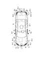
- FIG. 1 is a diagram showing components of a vehicle (hereinafter referred to as a host vehicle M) on which the vehicle control system 100 of the embodiment is mounted.
- the vehicle on which the vehicle control system 100 is mounted is, for example, a two-, three-, or four-wheeled vehicle, such as a vehicle powered by an internal combustion engine such as a diesel engine or gasoline engine, or an electric vehicle powered by a motor.
- hybrid vehicles having an internal combustion engine and an electric motor.
- An electric car is driven using electric power discharged by cells, such as a secondary battery, a hydrogen fuel cell, a metal fuel cell, and an alcohol fuel cell, for example.
- the vehicle M has sensors such as finders 20-1 to 20-7, radars 30-1 to 30-6, and a camera 40, a navigation device 50, and direction indicators TL1 to TL6. And the vehicle control system 100 are mounted.
- sensors such as finders 20-1 to 20-7, radars 30-1 to 30-6, and a camera 40, a navigation device 50, and direction indicators TL1 to TL6.
- vehicle control system 100 are mounted.
- the finders 20-1 to 20-7 are, for example, LIDAR (Light Detection and Ranging, or Laser Imaging Detection and Ranging) which measures the scattered light with respect to the irradiation light and measures the distance to the object.
- LIDAR Light Detection and Ranging, or Laser Imaging Detection and Ranging
- the finder 20-1 is attached to a front grill or the like
- the finders 20-2 and 20-3 are attached to the side of a vehicle body, a door mirror, the inside of a headlight, the vicinity of a side light, or the like.
- the finder 20-4 is attached to the trunk lid or the like
- the finders 20-5 and 20-6 are attached to the side of the vehicle body, the inside of the taillight, or the like.
- the finders 20-1 to 20-6 described above have, for example, a detection area of about 150 degrees in the horizontal direction.
- the finder 20-7 is attached to the roof or the like.
- the finder 20-7 has, for example, a detection area of 360 degrees in the horizontal direction.
- the radars 30-1 and 30-4 are, for example, long-distance millimeter-wave radars whose detection region in the depth direction is wider than other radars.
- the radars 30-2, 30-3, 30-5, and 30-6 are middle-range millimeter-wave radars that have a narrower detection area in the depth direction than the radars 30-1 and 30-4.
- the radar 30 detects an object by, for example, a frequency modulated continuous wave (FM-CW) method.
- FM-CW frequency modulated continuous wave
- the camera 40 is, for example, a digital camera using an individual imaging device such as a charge coupled device (CCD) or a complementary metal oxide semiconductor (CMOS).
- the camera 40 is attached to the top of the front windshield, the rear of the rearview mirror, and the like.
- the camera 40 for example, periodically and repeatedly images the front of the host vehicle M.
- the camera 40 may be a stereo camera including a plurality of cameras.
- the direction indicators TL1 to TL6 operate, for example, under the control of the vehicle control system 100.
- the direction indicators TL1 to TL6 include, for example, turn lamps that repeatedly turn on and off (flashing) in the operating state and turn off in the non-operating state.
- the direction indicators TL1 to TL6 may be constantly lit in the operating state.
- the direction indicators TL1 and TL2 are provided at the front end of the vehicle body such as the inside of a headlight
- the direction indicators TL3 and TL4 are provided at the side surface of the vehicle body, a door mirror, etc.
- the direction indicators TL5 and TL6 are It is provided at the rear end of the car body such as inside the taillight.
- the direction indicators TL3 and TL4 may be integral with the side lights, and the direction indicators TL5 and TL6 may be integral with a taillight such as a hazard lamp.
- a taillight such as a hazard lamp.
- the configuration shown in FIG. 1 is merely an example, and a part of the configuration may be omitted, or another configuration may be added.
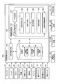
- FIG. 2 is a functional configuration diagram of a host vehicle M equipped with the vehicle control system 100 according to the embodiment.
- the navigation apparatus 50 the vehicle sensor 60, the display unit 62, the speaker 64, the accelerator pedal, the brake pedal, and the shift lever (or paddle shift)
- An operation device (an operator) 70 such as a steering wheel, and an operation detection sensor 72 such as an accelerator opening sensor, a brake depression sensor (brake switch), a shift position sensor, a steering angle sensor (or a steering torque sensor);
- a changeover switch 80, a driving force output device 90 for outputting a driving force for traveling, a steering device 92, a braking device 94, and a vehicle control system 100 are mounted.
- a multiplex communication line such as a CAN (Controller Area Network) communication line, a serial communication line, a wireless communication network or the like.
- the illustrated operation device is merely an example, and a joystick, a button, a dial switch, a GUI (Graphical User Interface) switch, etc. may be mounted on the vehicle M.
- the vehicle control system in the claims may include not only the vehicle control system 100 but also a configuration (such as the finder 20) other than the vehicle control system 100 among the configurations shown in FIG.
- the navigation device 50 has a GNSS (Global Navigation Satellite System) receiver, map information (navigation map), a touch panel display device functioning as a user interface, a speaker, a microphone, and the like.
- the navigation device 50 specifies the position of the host vehicle M by the GNSS receiver, and derives the route from the position to the destination specified by the user.
- the route derived by the navigation device 50 is provided to the target lane determination unit 110 of the vehicle control system 100.
- the position of the host vehicle M may be identified or supplemented by an INS (Inertial Navigation System) using the output of the vehicle sensor 60.
- INS Inertial Navigation System
- the navigation device 50 provides guidance by voice or navigation display on the route to the destination.
- the configuration for specifying the position of the host vehicle M may be provided independently of the navigation device 50.
- the navigation device 50 may be realized by, for example, the function of a terminal device such as a smartphone or a tablet terminal owned by the user. In this case, transmission and reception of information are performed between the terminal device and the vehicle control system 100 by wireless or wired communication.
- the vehicle sensor 60 includes a vehicle speed sensor that detects a vehicle speed, an acceleration sensor that detects an acceleration, a yaw rate sensor that detects an angular velocity about a vertical axis, an orientation sensor that detects the direction of the host vehicle M, and the like.
- the display unit 62 displays information as an image.
- the display unit 62 includes, for example, a liquid crystal display (LCD), an organic electroluminescence (EL) display device, a head-up display, and the like.
- the display unit 62 may be a display unit provided in the navigation device 50 or a display unit of an instrument panel that displays the state (speed, etc.) of the host vehicle M.
- the speaker 64 outputs the information as sound.
- the operation detection sensor 72 detects the amount of operation of the operation device 70.
- the operation detection sensor 72 outputs, to the vehicle control system 100, an accelerator opening degree, a brake depression amount, a shift position, a steering angle, a steering torque, and the like as detection results.
- the detection result of the operation detection sensor 72 may be directly output to the driving force output device 90, the steering device 92, or the brake device 94 depending on the operation mode.
- the changeover switch 80 is a switch operated by a vehicle occupant.
- the switch 80 receives an operation of the vehicle occupant, generates a driving mode designation signal for specifying the driving mode of the host vehicle M, and outputs the driving mode designation signal to the switching control unit 170.
- the changeover switch 80 may be either a GUI switch or a mechanical switch.
- the driving force output device 90 outputs traveling driving force (torque) for the vehicle to travel to the driving wheels.
- the driving force output device 90 includes an engine, a transmission, and an engine ECU (Electronic Control Unit) that controls the engine.
- the driving force output device 90 includes a traveling motor and a motor ECU that controls the traveling motor.
- the driving force output device 90 includes an engine, a transmission, an engine ECU, a traveling motor, and a motor ECU.
- the engine ECU adjusts the throttle opening degree, shift stage, and the like of the engine according to the information input from the traveling control unit 160 described later.
- the motor ECU adjusts the duty ratio of the PWM signal given to the traveling motor in accordance with the information input from the traveling control unit 160.
- the driving force output device 90 includes an engine and a traveling motor, the engine ECU and the motor ECU control the traveling driving force in coordination with each other in accordance with the information input from the traveling control unit 160.
- the steering device 92 includes, for example, a steering ECU and an electric motor.
- the electric motor for example, applies a force to the rack and pinion mechanism to change the direction of the steered wheels.
- the steering ECU drives the electric motor according to the information input from the vehicle control system 100 or the information of the steering angle or steering torque input, and changes the direction of the steered wheels.
- the brake device 94 is, for example, an electric servo brake device including a brake caliper, a cylinder that transmits hydraulic pressure to the brake caliper, an electric motor that generates hydraulic pressure in the cylinder, and a braking control unit.
- the braking control unit of the electric servo brake device controls the electric motor in accordance with the information input from the traveling control unit 160 so that the brake torque corresponding to the braking operation is output to each wheel.
- the electric servo brake device may be provided with a mechanism for transmitting the hydraulic pressure generated by the operation of the brake pedal to the cylinder via the master cylinder as a backup.
- the brake device 94 is not limited to the electric servo brake device described above, but may be an electronically controlled hydraulic brake device.
- the electronically controlled hydraulic brake device controls the actuator according to the information input from the travel control unit 160 to transmit the hydraulic pressure of the master cylinder to the cylinder.
- the brake device 94 may include a regenerative brake by a traveling motor that may be included in the driving force output device 90.
- the regenerative brake uses the electric power generated by the traveling motor which may be included in the driving force output device 90.
- the vehicle control system 100 is realized by, for example, one or more processors or hardware having equivalent functions.
- the vehicle control system 100 may have a combination of a processor such as a central processing unit (CPU), a storage device, an ECU in which a communication interface is connected by an internal bus, or an MPU.
- a processor such as a central processing unit (CPU), a storage device, an ECU in which a communication interface is connected by an internal bus, or an MPU.
- the vehicle control system 100 includes, for example, a target lane determination unit 110, an automatic driving control unit 120, and a storage unit 190.
- the autonomous driving control unit 120 includes a vehicle position recognition unit 122, an external world recognition unit 130, an action plan generation unit 140, a track generation unit 150, a travel control unit 160, a switching control unit 170, and direction instructions. And a controller control unit 180.
- the track generation unit 150 and the travel control unit 160 are examples of a “control unit”.
- the processor executes a program (software) to realize part or all of the target lane determination unit 110 and each part of the autonomous driving control unit 120. Also, some or all of these may be realized by hardware such as LSI (Large Scale Integration) or ASIC (Application Specific Integrated Circuit), or may be realized by a combination of software and hardware.
- LSI Large Scale Integration
- ASIC Application Specific Integrated Circuit
- the storage unit 190 stores, for example, information such as high accuracy map information 192, target lane information 194, action plan information 196, and the like.
- the storage unit 190 is realized by a read only memory (ROM), a random access memory (RAM), a hard disk drive (HDD), a flash memory, or the like.
- the program executed by the processor may be stored in advance in the storage unit 190, or may be downloaded from an external device via an in-vehicle Internet facility or the like.
- the program may be installed in the storage unit 190 by mounting a portable storage medium storing the program in a drive device (not shown).
- the vehicle control system 100 may be distributed by a plurality of computer devices.
- the target lane determination unit 110 is realized by, for example, an MPU.
- the target lane determination unit 110 divides the route provided from the navigation device 50 into a plurality of blocks (for example, in units of 100 [m] in the traveling direction of the vehicle), and refers to the high accuracy map information 192 for each block Determine your target lane.
- the target lane determination unit 110 determines, for example, which lane from the left the vehicle should travel.
- the target lane determination unit 110 determines the target lane so that the host vehicle M can travel on a rational travel route for advancing to the branch destination, for example, when there is a branch point or a junction point in the route. .
- the target lane determined by the target lane determination unit 110 is stored in the storage unit 190 as target lane information 194.
- the high accuracy map information 192 is map information that is more accurate than the navigation map of the navigation device 50.
- the high accuracy map information 192 includes, for example, information on the center of the lane or information on the boundary of the lane. Also, the high accuracy map information 192 may include road information, traffic regulation information, address information (address / zip code), facility information, telephone number information, and the like.
- the road information includes information indicating the type of road such as expressways, toll roads, national roads, and prefectural roads, the number of lanes of the road, the width of each lane, the slope of the road, the position of the road (longitude, latitude, height 3) (including three-dimensional coordinates), curvature of a curve of a lane, locations of merging and branching points of lanes, and information such as signs provided on roads.
- the traffic regulation information includes information that the lane is blocked due to construction work, traffic accident, traffic jam or the like.
- the vehicle position recognition unit 122 of the automatic driving control unit 120 receives information from the high accuracy map information 192 stored in the storage unit 190, the finder 20, the radar 30, the camera 40, the navigation device 50, or the vehicle sensor 60. And recognizes the relative position of the host vehicle M with respect to the travel lane and the lane in which the host vehicle M is traveling (traveling lane).
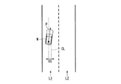
- FIG. 3 is a diagram showing how the vehicle position recognition unit 122 recognizes the relative position of the vehicle M with respect to the traveling lane L1.
- the host vehicle position recognition unit 122 receives the deviation OS from the center CL of the travel lane of the reference point (for example, the center of gravity or the center of the rear wheel axis) of the host vehicle M and the center CL of the travel lane
- the angle ⁇ to be formed is recognized as the relative position of the host vehicle M with respect to the traveling lane L1.
- the host vehicle position recognition unit 122 recognizes the position of the reference point of the host vehicle M with respect to any one side end of the host lane L1 as the relative position of the host vehicle M with respect to the traveling lane. It is also good.
- the relative position of the host vehicle M recognized by the host vehicle position recognition unit 122 is provided to the target lane determination unit 110.
- the external world recognition unit 130 recognizes the position of the surrounding vehicle and the state of the speed, acceleration, and the like based on the information input from the finder 20, the radar 30, the camera 40 and the like.
- the surrounding vehicle is, for example, a vehicle traveling around the host vehicle M and traveling in the same direction as the host vehicle M.
- the position of the surrounding vehicle may be represented by a representative point such as the center of gravity or a corner of the other vehicle, or may be represented by an area represented by the contour of the other vehicle.
- the "state" of the surrounding vehicle may include the acceleration of the surrounding vehicle, whether it is changing lanes (or whether it is going to change lanes), which is grasped based on the information of the various devices.
- the external world recognition unit 130 recognizes the position of the driver in the recognized peripheral vehicle. For example, the external world recognition unit 130 estimates the position of the window frame from the shape of the vehicle body of the surrounding vehicle, predicts the seat position of the driver from the arrangement pattern of the window frame, and recognizes this predicted position as the driver position. Do. In addition, the external world recognition unit 130 may recognize the position of the driver by estimating the seat position in the vehicle based on the position of the door mirror of the peripheral vehicle, the position of the wheel (tire), and the like.
- the external world recognition unit 130 may perform image processing such as feature point matching on the captured image of the camera 40 to recognize the position of the driver (human) from the captured image, or the finder 20 or The position of the driver may be recognized by performing analysis processing of a spectrum indicating characteristics of light and radio waves reflected by a human on the detection result by the radar 30.
- the outside world recognition unit 130 may also recognize positions of guardrails, utility poles, parked vehicles, pedestrians, and other objects.
- the external world recognition unit 130 is configured to drop objects on the roadway, stop nearby vehicles, targets in the vicinity of the construction site (for example, pylons and billboards), and walk on the target lane determined by the target lane determination unit 110. Recognize obstacles such as people.
- the action plan generation unit 140 sets a start point of the autonomous driving and / or a destination of the autonomous driving.
- the starting point of the autonomous driving may be the current position of the host vehicle M or a point at which the operation for instructing the autonomous driving is performed.
- the action plan generation unit 140 generates an action plan in the section between the starting point and the destination of the automatic driving.
- generation part 140 may produce
- the action plan is composed of, for example, a plurality of events that are sequentially executed.
- Events include, for example, a deceleration event for decelerating the host vehicle M, an acceleration event for accelerating the host vehicle M, a lane keep event for traveling the host vehicle M not to deviate from the target lane, and a lane change event for changing the target lane
- an overtaking event that causes the host vehicle M to overtake the preceding vehicle
- a branch event that changes the lane to a desired lane at a branch point, or causes the host vehicle M to travel so as not to deviate from the current target lane.
- a merging event or the like which accelerates / decelerates the host vehicle M in the confluence lane of and changes the target lane is included.
- the action plan generation unit 140 sets a lane change event, a branch event, or a merging event at a point where the target lane determined by the target lane determination unit 110 is switched.
- Information indicating the action plan generated by the action plan generation unit 140 is stored in the storage unit 190 as action plan information 196.
- FIG. 4 is a diagram showing an example of an action plan generated for a certain section.
- the action plan generation unit 140 generates an action plan necessary for the host vehicle M to travel on the target lane indicated by the target lane information 194.
- the action plan generation unit 140 may dynamically change the action plan according to the change in the situation of the host vehicle M, regardless of the target lane information 194. For example, in the action plan generation unit 140, the speed of the peripheral vehicle recognized by the external world recognition unit 130 exceeds the threshold while the vehicle is traveling, or the movement direction of the peripheral vehicle traveling in the lane adjacent to the own lane In the case of turning, the event set in the driving section where the host vehicle M is to travel is changed.
- the recognition result of the external world recognition unit 130 causes the vehicle to exceed the threshold from the rear of the lane in the lane change destination during the lane keep event. If it is determined that the vehicle has progressed at the speed of 1, the action plan generation unit 140 may change the event following the lane keeping event from a lane change event to a deceleration event or a lane keeping event. As a result, the vehicle control system 100 can safely cause the host vehicle M to travel automatically even when a change occurs in the state of the outside world.
- FIG. 5 is a diagram showing an example of the configuration of the trajectory generation unit 150.
- the track generation unit 150 includes, for example, a traveling mode determination unit 151, a track candidate generation unit 152, an evaluation / selection unit 153, and a lane change control unit 154.
- the traveling mode determination unit 151 determines one of the traveling modes among constant speed traveling, follow-up traveling, deceleration traveling, curve traveling, obstacle avoidance traveling, and the like. For example, when there is no other vehicle ahead of the host vehicle M, the traveling mode determination unit 151 determines that the traveling mode is constant speed traveling. In addition, the traveling mode determination unit 151 determines the traveling mode as the following traveling when following the traveling vehicle. Further, the traveling mode determining unit 151 determines the traveling mode to be the decelerating traveling when the external world recognition unit 130 recognizes the deceleration of the leading vehicle, or when an event such as stopping or parking is performed.
- the traveling mode determination unit 151 determines the traveling mode to be a curve traveling when the external world recognition unit 130 recognizes that the host vehicle M is approaching a curved road. In addition, when the external world recognition unit 130 recognizes an obstacle ahead of the host vehicle M, the traveling mode determination unit 151 determines the traveling mode as obstacle avoidance traveling.
- the track candidate generation unit 152 generates track candidates based on the traveling mode determined by the traveling mode determination unit 151.
- the track in the present embodiment is a set of target positions (track points) to be reached by the reference point (for example, the center of gravity or the rear wheel axis center) of the vehicle M at predetermined future time intervals (or at predetermined travel distances). .
- the trajectory candidate generation unit 152 sets the target velocity of the host vehicle M based on at least the speed of the target OB existing in front of the host vehicle M recognized by the external world recognition unit 130 and the distance between the host vehicle M and the target OB. calculate.
- the trajectory candidate generation unit 152 generates one or more trajectories based on the calculated target velocity.
- the target OB includes a vehicle ahead, a junction such as a junction, a junction, a point such as a target point, and an object such as an obstacle.
- FIG. 6 is a diagram showing an example of trajectory candidates generated by the trajectory candidate generation unit 152. As shown in FIG. In FIG. 6 and FIG. 9 described later, only representative trajectories or trajectories selected by the evaluation / selection unit 153 out of a plurality of trajectory candidates that can be set will be described. As shown in (A) of FIG. 6, for example, the trajectory candidate generation unit 152 sets K (1) and K (2) every time a predetermined time ⁇ t has elapsed from the current time based on the current position of the host vehicle M. , K (3),... Hereinafter, when these orbital points are not distinguished, they may be simply described as "orbital point K".
- the trajectory candidate generation unit 152 sets a plurality of trajectory points K at equal intervals as shown in (A) in FIG.
- the trajectory candidate generation unit 152 may generate only one trajectory.
- the track candidate generation unit 152 is reached as shown in (B) in FIG.
- the interval is made wider as the trajectory point K is earlier, and the trajectory is made narrower as the trajectory point K is later.
- a leading vehicle may be set as the target OB, or a junction other than the leading vehicle, a branch point, a point such as a target point, an obstacle, or the like may be set as the target OB.
- the traveling control unit 160 described later decelerates the host vehicle M.
- the trajectory candidate generation unit 152 When the traveling mode is determined to be curve traveling by the traveling mode determination unit 151, as illustrated in (C) in FIG. 6, the trajectory candidate generation unit 152 performs a plurality of trajectory points K according to the curvature of the road. Arrange while changing the lateral position (position in the lane width direction) to the traveling direction of M. Further, as shown in (D) of FIG. 6, when there is an obstacle OB such as a person or a stopped vehicle on the road in front of the own vehicle M, the trajectory candidate generation unit 152 avoids the obstacle OB. A plurality of track points K are arranged so as to travel.
- the evaluation / selection unit 153 evaluates the track candidates generated by the track candidate generation unit 152, for example, from two viewpoints of planability and safety, and selects a track to be output to the traveling control unit 160. .
- the track is highly evaluated if the trackability to the already generated plan (for example, the action plan) is high and the total length of the track is short. For example, if it is desired to change lanes to the right, a track that once changes lanes to the left and then back is a low rating.
- viewpoint of safety for example, the distance between the host vehicle M and an object (such as a surrounding vehicle) is longer, and the smaller the acceleration / deceleration, the change amount of the steering angle, etc.
- the lane change control unit 154 operates when a lane change event, a branch event, a merging event or the like is performed, that is, when a broad lane change is performed.
- FIG. 7 is a flowchart showing an example of the flow of processing executed when a lane change event is performed. The process will be described with reference to FIGS. 7 and 8.
- the lane change control unit 154 selects two peripheral vehicles from the adjacent vehicles that are adjacent lanes adjacent to the lane where the host vehicle M is traveling (the own lane) and that travels in the adjacent lanes of the lane change destination.
- the target position TA is set between these surrounding vehicles (step S100).
- peripheral vehicles traveling immediately before the target position TA in the adjacent lane will be referred to as a front reference vehicle mB
- peripheral vehicles traveling immediately after the target position TA in the adjacent lane will be referred to as a rear reference vehicle mC.
- the target position TA is a relative position based on the positional relationship between the host vehicle M and the front reference vehicle mB and the rear reference vehicle mC.
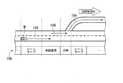
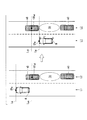
- FIG. 8 is a diagram showing how the target position TA is set.
- mA represents a front vehicle
- mB represents a front reference vehicle
- mC represents a rear reference vehicle.
- the arrow d indicates the traveling (traveling) direction of the host vehicle M
- L1 indicates the host lane
- L2 indicates the adjacent lane.
- the lane change control unit 154 sets the target position TA between the front reference vehicle mB and the rear reference vehicle mC on the adjacent lane L2.
- the lane change control unit 154 determines whether the primary condition for determining whether the lane change is possible at the target position TA (that is, between the front reference vehicle mB and the rear reference vehicle mC) is satisfied or not. It determines (step S102).
- the primary condition is that, for example, there are no surrounding vehicles in the prohibited area RA provided in the adjacent lane, and TTCs of the own vehicle M and the front reference vehicle mB and the rear reference vehicle mC are respectively larger than the threshold It is.
- this determination condition is an example when the target position TA is set on the side of the host vehicle M. If the primary condition is not satisfied, the lane change control unit 154 returns the process to step S100 and resets the target position TA. At this time, speed control for moving to the side of the target position TA is performed by waiting until the timing at which the target position TA that satisfies the primary condition can be set or changing the target position TA. May be
- the lane change control unit 154 projects the vehicle M on the lane L2 as the lane change destination, and sets a prohibited area RA with a slight allowance distance before and after.
- the prohibited area RA is set as an area extending from one end of the lane L2 in the lateral direction to the other end.
- the lane change control unit 154 calculates the extension line FM and the collision margin time TTC (B) of the front reference vehicle mB, and the rear line reference vehicle TTC (C) of the extension line RM and the rear reference vehicle mC.
- the collision margin time TTC (B) is a time derived by dividing the distance between the extension line FM and the front reference vehicle mB by the relative speed of the host vehicle M and the front reference vehicle mB.
- the collision margin time TTC (C) is a time derived by dividing the distance between the extension line RM and the rear reference vehicle mC by the relative speed of the host vehicle M and the rear reference vehicle mC.
- the trajectory candidate generation unit 152 determines that the primary condition is satisfied when the collision margin time TTC (B) is larger than the threshold Th (B) and the collision margin time TTC (C) is larger than the threshold Th (C). Do.
- the thresholds Th (B) and Th (C) may be the same value or different values.
- the lane change control unit 154 causes the trajectory candidate generation unit 152 to generate a trajectory candidate for lane change (step S104).
- FIG. 9 is a diagram showing how a track for lane change is generated.
- the track candidate generation unit 152 assumes that the front vehicle mA, the front reference vehicle mB and the rear reference vehicle mC travel with a predetermined speed model, and the speed models of these three vehicles and the speed of the host vehicle M And generates a candidate for a trajectory such that the host vehicle M is located between the front reference vehicle mB and the rear reference vehicle mC at a certain time in the future without interference or contact with the forward vehicle mA. .
- the track candidate generation unit 152 generates a spline curve or the like from the current position of the host vehicle M to the position of the front reference vehicle mB at a certain time in the future, the center of the lane to be changed, and the lane change end point It connects smoothly using a polynomial curve, and a predetermined number of orbital points K are arranged on this curve at equal or unequal intervals.
- the trajectory candidate generation unit 152 generates a trajectory such that at least one of the trajectory points K is disposed within the target position TA.
- FIG. 10 is a diagram showing an example of the scene where the target position TA is reset.
- the lane change control unit 154 refers to the rear reference vehicle mC referenced when setting the target position TA.
- a new front reference vehicle mB is set, and a vehicle existing behind the newly set front reference vehicle mB is set as a new rear reference vehicle mC, and the reset front reference vehicle mB and rear reference vehicle mC are set. And reset the target position TA.
- the lane change control unit 154 similarly sets the front reference vehicle mB referred to when setting the target position TA as a new rear reference vehicle mC, and in front of the newly set rear reference vehicle mC.
- the existing vehicle may be set as a new front reference vehicle mB, and the target position TA may be reset between the reset front reference vehicle mB and the rear reference vehicle mC.
- the track candidate generation unit 152 generates a track for changing the lane of the host vehicle M between the reset front reference vehicle mB and the rear reference vehicle mC.
- the evaluation / selection unit 153 determines whether or not the trajectory candidate satisfying the setting condition has been generated (step S106).
- the setting condition is, for example, that an evaluation value equal to or greater than a threshold value is obtained from the viewpoint of the planability and safety described above.
- the evaluation / selection unit 153 selects, for example, the candidate of the track with the highest evaluation value, outputs information of the track to the travel control unit 160, and causes lane change. (Step S108).
- step S100 if a trajectory satisfying the set condition can not be generated, the process returns to step S100. At this time, as in the case where a negative determination is obtained in step S102, processing may be performed to be in the standby state or to reset the target position TA.
- the traveling control unit 160 controls the driving force output device 90, the steering device 92, and the braking device 94 so that the vehicle M passes the track generated by the track candidate generating unit 152 as scheduled.
- the switching control unit 170 switches the driving mode based on an operation for instructing the operating device 70 to accelerate, decelerate or steer, as well as switching the driving mode based on the driving mode designation signal input from the changeover switch 80. For example, the switching control unit 170 switches from the automatic driving mode to the manual driving mode when the state where the operation amount input from the operation detecting sensor 72 exceeds the threshold continues for the reference time or more. In addition, the switching control unit 170 switches the operation mode from the automatic operation mode to the manual operation mode near the destination of the automatic operation.
- the switching control unit 170 When switching from the manual operation mode to the automatic operation mode, the switching control unit 170 performs this based on the operation mode designation signal input from the switching switch 80. In addition, after switching from the automatic driving mode to the manual driving mode, if the operation for instructing the operating device 70 to accelerate, decelerate or steer is not detected for a predetermined time, control to return to the automatic driving mode is performed. It may be
- FIG. 11 is a diagram showing an example of the configuration of the direction indicator control unit 180.
- the direction indicator control unit 180 includes, for example, an operation timing determination unit 181, an operation continuation determination unit 182, and an operation control unit 183.
- the operation timing determination unit 181 causes the vehicle M and one or both of the front reference vehicle mB and the rear reference vehicle mC to Set the reference position to be referenced when comparing the position of.
- the reference position to be set to the host vehicle M is denoted by reference symbol CP M
- the reference position to be set to the front reference vehicle mB is denoted by reference symbol CP mB
- the reference position to be set to the rear reference vehicle mC is denoted by CP mC Do.
- Operation timing determination unit 181 compares the reference position CP M of the vehicle M, and one or both of the reference position CP mC reference position CP mB and rear reference vehicle mC forward reference vehicle mB, direction indicator Determine the timing to operate the machine TL.
- the reference position CPM of the host vehicle M is, for example, a position where the direction indicator TL is provided, and the installation position of the direction indicators TL1 and TL2 on the front end of the vehicle, and the direction indicators TL3 and TL4 on the vehicle side. It may be either the installation position, the installation position of the direction indicators TL5 and TL6 on the rear end side of the vehicle, or the center of these positions.
- the reference position CP mB of the front reference vehicle mB and the reference position CP mC of the rear reference vehicle mC are, for example, positions of drivers of the respective vehicles.
- the actuation timing determination unit 181 determines that the reference position CP mB of the forward reference vehicle mB matches the reference position CP M of the subject vehicle M. or compared to the reference position CP mB of the forward reference vehicle mB, the reference position CP M of the own vehicle M, the timing at which the rear with respect to the traveling direction of the vehicle (timing later than the matching timing), the target position It is decided to activate the turn indicator TL on the adjacent lane side where TA is set.
- the "target position TA is behind the vehicle", for example, the reference position CP M of the vehicle M than the reference position CP mB of the forward reference vehicle mB referenced when setting the target position TA is self It means being forward with respect to the direction of travel of the vehicle.
- the operation timing determining unit 181 if the target position TA set in the adjacent lane is ahead of the vehicle, and the reference position CP M of the reference position CP mC and the vehicle M of backward reference vehicle mC match timing or compared to the reference position CP mC backward reference vehicle mC, the reference position CP M of the own vehicle M, the timing at which the front with respect to the traveling direction of the vehicle (timing later than the matching timing), the target position The timing is determined as the timing at which the turn indicator TL on the adjacent lane side where the TA is set is activated.
- the "target position TA is ahead of the vehicle", for example, the reference position CP M of the vehicle M than the reference position CP mC backward reference vehicle mC referenced when setting the target position TA is self It says that it is the rear in the direction of movement of the vehicle.
- the operation timing determining section 181 the reference position CP M of the own vehicle M, it becomes forward than the reference position CP mC backward reference vehicle mC described above, the ratio to the reference position CP mB of the forward reference vehicle mB It is also possible to decide to activate the turn indicator TL on the adjacent lane side where the target position TA has been set, at the timing when it comes to the rear.
- the operation continuation determination unit 182 is a direction indicator based on the change of the action plan (event) by the action plan generation unit 140, the determination of the possibility of the lane change by the lane change control unit 154, the switching of the control mode by the switching control unit 170, etc. After TL is activated, it is determined whether to continue lighting (flashing) or turning it off.
- the direction changer TL is activated, and the direction change event is changed to another event by the action plan generation unit 140 before the host vehicle M reaches the target position TA. It is decided to turn off the indicator TL.
- the operation continuation determination unit 182 determines to turn off the turn indicator TL when the switching control unit 170 switches to the manual operation mode by the operation by the driver during the automatic operation mode.
- the operation continuation determination unit 182 changes the lane by the rear reference vehicle mC approaching the front reference vehicle mB, etc. If it is continuously determined whether or not the lane change with respect to the other target position TA is to be made if the necessary inter-vehicle distance is not sufficiently secured, it is decided to continue the operation of the direction indicator TL.
- the operation control unit 183 operates (always lights or blinks) the turn indicator TL on the adjacent lane side where the target position TA is set at the timing determined by the operation timing determination unit 181. Further, the operation control unit 183 keeps the direction indicator TL activated or extinguished according to the determination result by the operation continuation determination unit 182.
- FIG. 12 is a flowchart showing an example of the flow of processing by the direction indicator control unit 180.
- the operation timing determination unit 181 determines whether the target position TA set by the lane change control unit 154 is ahead of the host vehicle (step S200). When the target position TA is in front of the host vehicle, the operation timing determination unit 181 derives the time when the reference position CP M of the host vehicle M reaches the reference position CP mC of the rear reference vehicle mC (step S202). For example, when the operation timing determination unit 181 sets the current speed of the host vehicle M and the speed of the rear reference vehicle mC constant, the relative distance from the reference position CP M to the reference position CP mC is constant. The operation time of the turn indicator TL is derived by deriving the time required to run through the road.
- the operation timing determination unit 181 derives the time when the reference position CP mB of the front reference vehicle mB reaches the reference position CPM of the vehicle M (Step S204). For example, when the operation timing determination unit 181 sets the current speed of the host vehicle M and the speed of the forward reference vehicle mB constant, the relative distance from the forward reference vehicle mB to the reference position CP M from the reference position CP mB The operation time of the turn indicator TL is derived by calculating the time required to run through the road.
- the operation control unit 183 waits until the current time reaches the operation time derived by the operation timing determination unit 181 (step S206), and the timing when the current time becomes the operation time or from the operation time
- the turn indicator TL is activated at the timing when a certain remaining time has passed (step S208).
- FIG. 13 is a view showing an example of a scene in which the target position TA is set in front of the host vehicle M.
- the turn indicator TL indicates that the reference position CPM of the host vehicle M coincides with the reference position CP mC of the rear reference vehicle mC, or the reference position CP mC of the rear reference vehicle mC is the host It is operated at a timing behind the M reference position CPM.
- the reference position CP M of the vehicle M may be a right front turn signals TL2, middle right turn signal TL4, it may be a right rear direction indicators TL6.
- the operation timing determination unit 181 sets a reference line L mC virtually extended in the lane width direction from the reference position CP mC of the rear reference vehicle mC, and a reference position CP of the own vehicle M. Assuming a reference line LM virtually extending in the lane width direction from M , the operation timing is determined from the anteroposterior relationship between these reference lines.
- Direction indicator control unit 180 by operating the reference line L M timing coincides with the reference line L mC or reference line L M is the reference line L direction indicator TL at the timing located behind the mC,, e.g.
- the intention of the host vehicle M to break in front of the rear reference vehicle mC can be transmitted to the driver of the rear reference vehicle mC, and the driver of the rear reference vehicle mC can be considered.
- FIG. 14 is a diagram showing an example of a scene in which the target position TA is set to the rear of the host vehicle M.
- the turn indicator TL indicates that the reference position CPM of the host vehicle M coincides with the reference position CP mB of the front reference vehicle mB, or that the reference position CP mB of the front reference vehicle mB is the host It is operated at the timing ahead of the reference position CPM of M.
- the reference position CP M of the vehicle M is preferably a right front turn signal TL2.
- the operation timing determination unit 181 assumes a reference line L mB virtually extended in the lane width direction from the reference position CP mB of the front reference vehicle mB and the reference line L M.
- the operation timing is determined from the anteroposterior relationship between these reference lines.
- Direction indicator control unit 180 by operating the reference line L M is the reference line L mB Match timing or the reference line L M is the reference line L direction indicator TL at the timing located in front of the mB, e.g. It is possible to prevent misunderstanding that the lighting of the direction indicator TL is less likely to be visually recognized by the driver of the front reference vehicle mB, and has an intention to cut in front of the front reference vehicle mB.
- the actuation continuation determination unit 182 determines whether or not the lane change is completed (FIG. 12: step S210). When the lane change is completed, the operation control unit 183 turns off the operated direction indicator TL (step S212).
- the operation continuation determination unit 182 determines whether the target position TA is reset by the lane change control unit 154 (step S214). When the target position TA is not reset, the operation continuation determination unit 182 determines that the lane change event has been changed to another event or the operation mode has been switched to the automatic operation mode, and the operation control unit 183 described above. The processing of S212 is performed.
- the operation continuation determination unit 182 determines to continue the operation (step S216), and returns to the process of S200 described above.
- the process of this flowchart is complete
- FIG. 15 is a diagram showing an example of a situation in which the operation of the turn indicator TL is continued.
- the target position TA1 is set between the vehicle m1 and the vehicle m2 by the lane change control unit 154
- the traveling control unit 160 controls the driving force output device 90, the steering device 92, and the braking device 94 to control the vehicle M.
- the vehicle travels toward the target position TA1.
- the turn signal control unit 180 the reference position CP M of the vehicle M overtakes the reference position CP mC vehicle m2 is a rear reference vehicle mC, operates the direction indicator TL, the driver of the vehicle m2 Tell your intention to interrupt.
- the vehicle m2 may accelerate and a sufficient inter-vehicle distance may not be secured between the vehicle m1 and the vehicle m2.
- the lane change control unit 154 newly resets the target position TA2 between the vehicle m2 and the vehicle m3. If it is determined that the lane change is possible for this target position TA2, the direction indicator control unit 180 continues the operation of the direction indicator TL.
- the vehicle control system 100 causes the host vehicle M to travel toward the target position TA2
- the vehicle control system 100 transmits the intention to change lanes to drivers of surrounding vehicles by constantly operating the direction indicator TL. Can.
- the possibility that the host vehicle M can change lanes to the adjacent lane L2 is improved.
- the direction indicator TL is operated based on the relative position between the front reference vehicle mB traveling immediately before the target position TA or the rear reference vehicle mC traveling immediately after and the host vehicle M.
- the timing is determined. Therefore, it is possible to give notice of lane change at an appropriate timing.
- the timing reference position CP M of the vehicle M is equal to the reference position CP mC backward reference vehicle mC or reference position CP mC backward reference vehicle mC is the vehicle M based direction indicator TL is operated at timing at which the rear position CP M. Therefore, the intention of the host vehicle M to break in front of the rear reference vehicle mC can be transmitted to the driver of the rear reference vehicle mC, and the driver of the rear reference vehicle mC can be considered.
- the timing reference position CP M of the vehicle M is equal to the reference position CP mB of the forward reference vehicle mB
- the reference position CP mB of the forward reference vehicle mB of the vehicle M based direction indicator TL is operated at timing at which the forward position CP M. Therefore, it is difficult for the driver of the front reference vehicle mB to visually recognize that the turn indicator TL is lit, and it is possible to prevent misunderstanding that the driver has an intention to cut in front of the front reference vehicle mB.
- the turn indicator TL is not turned off even when it is not possible to change the lane for one target position TA, and while the lane change feasibility determination for the other target positions TA is performed.
- the turn indicator TL continues to operate. Therefore, the certainty of lane change can be enhanced.
- the operation timing determination unit 181 described above changes the setting position of the reference position CP mB based on the relative speed between the host vehicle M and the front reference vehicle mB.
- the operation timing determination unit 181 changes the setting position of the reference position CP mC based on the relative speed of the host vehicle M and the rear reference vehicle mC.
- FIG. 16 is a diagram for describing a method of determining the setting positions of the reference positions CP mB and CP mC .
- the horizontal axis represents the setting position of the reference position CP mB and CP mC, vertical axis, and the velocity V M of the vehicle M, the speed of the speed V mB or rear reference vehicle mC forward reference vehicle mB It represents the relative velocity with VmC .
- the reference position CP mC is higher as the velocity V M of the host vehicle M is larger than the speed V mC of the rear reference vehicle mC.
- the actuation timing determination unit 181 sets the reference position CP mC to the rear reference as the relative velocity of the host vehicle M with respect to the rear reference vehicle mC increases as a positive value. It is set to be closer to the rear end side of the vehicle mC.
- the direction indicator control unit 180 operates the direction indicator TL earlier when the host vehicle M passes the rear reference vehicle mC.
- the direction indicator control unit 180 can more reliably perform the driver of the rear reference vehicle mC even in a situation where the error in the position of the rear reference vehicle mC recognized becomes larger as the relative speed increases.
- the lighting of the direction indicator TL can be visually recognized.
- the reference position CP mB is lower as the velocity VM of the host vehicle M is smaller than the speed V mB of the front reference vehicle mB.
- And is set to be closer to the front end side of the front reference vehicle mB.
- the operation timing determination unit 181 sets the reference position according to the relative speed of the host vehicle M relative to the front reference vehicle mB becoming a negative value.
- CP mB is set to be closer to the front end side of the front reference vehicle mB.
- the rear end of the front reference vehicle mB Since the reference position CP mB is set on the side, the turn indicator TL is turned on further rearward than the position of the driver of the front reference vehicle mB. As a result, it becomes more difficult for the driver of the front reference vehicle mB to visually recognize lighting of the direction indicator TL.
- the direction indicator TL is activated in front of the driver's position of the front reference vehicle mB.
- the forward reference vehicle mB is faster than the own vehicle M, the intention to change the lane of the own vehicle M tends to be ignored, and has an intention to cut in front of the forward reference vehicle mB. It is possible to activate the turn indicator TL earlier without giving a misunderstanding.
- FIG. 17 is a diagram showing an example of a scene in which the inter-vehicle distance between the front reference vehicle mB and the rear reference vehicle mC is enlarged.
- ⁇ L represents the inter-vehicle distance before the turn indicator TL is activated
- ⁇ L # represents the inter-vehicle distance after the turn indicator TL is activated.
- the turn indicator controller 180 changes the lane ahead of the rear reference vehicle mC, and then turns the turn indicators TL5 and TL6. Operate. Thereby, the vehicle control system 100 can convey the intention of appreciation to the driver of the rear reference vehicle mC.
Landscapes
- Engineering & Computer Science (AREA)
- Mechanical Engineering (AREA)
- Transportation (AREA)
- Automation & Control Theory (AREA)
- Traffic Control Systems (AREA)
- Control Of Driving Devices And Active Controlling Of Vehicle (AREA)
Abstract
La présente invention concerne un système de commande de véhicule (100) qui comporte : une unité de commande qui règle une position cible, qui est utilisée comme cible lorsqu'un véhicule hôte est amené à changer de voies, sur une voie adjacente qui est adjacente à une voie de véhicule hôte le long de laquelle le véhicule hôte se déplace, et amène le véhicule hôte à changer de voies vers la position cible ; et une unité de commande de feu indicateur de direction (180) qui décide, sur la base de la relation relative entre le véhicule hôte et un véhicule qui se déplace juste devant ou juste derrière la position cible réglée par l'unité de commande, la temporisation selon laquelle un feu indicateur de direction disposé dans le véhicule hôte est actionné.
Priority Applications (3)
| Application Number | Priority Date | Filing Date | Title |
|---|---|---|---|
| US16/082,321 US11066073B2 (en) | 2016-03-15 | 2017-03-08 | Vehicle control system, vehicle control method, and vehicle control program |
| CN201780014932.3A CN108778879B (zh) | 2016-03-15 | 2017-03-08 | 车辆控制系统、车辆控制方法及存储介质 |
| JP2018505862A JP6600897B2 (ja) | 2016-03-15 | 2017-03-08 | 車両制御システム、車両制御方法、および車両制御プログラム |
Applications Claiming Priority (2)
| Application Number | Priority Date | Filing Date | Title |
|---|---|---|---|
| JP2016-051332 | 2016-03-15 | ||
| JP2016051332 | 2016-03-15 |
Publications (1)
| Publication Number | Publication Date |
|---|---|
| WO2017159509A1 true WO2017159509A1 (fr) | 2017-09-21 |
Family
ID=59850389
Family Applications (1)
| Application Number | Title | Priority Date | Filing Date |
|---|---|---|---|
| PCT/JP2017/009322 WO2017159509A1 (fr) | 2016-03-15 | 2017-03-08 | Système de commande de véhicule, procédé de commande de véhicule et programme de commande de véhicule |
Country Status (4)
| Country | Link |
|---|---|
| US (1) | US11066073B2 (fr) |
| JP (1) | JP6600897B2 (fr) |
| CN (1) | CN108778879B (fr) |
| WO (1) | WO2017159509A1 (fr) |
Cited By (19)
| Publication number | Priority date | Publication date | Assignee | Title |
|---|---|---|---|---|
| JP2017206241A (ja) * | 2016-05-16 | 2017-11-24 | 株式会社デンソー | 支援装置、支援方法 |
| CN109515439A (zh) * | 2018-11-13 | 2019-03-26 | 北京四维图新科技股份有限公司 | 自动驾驶控制方法、装置、系统及存储介质 |
| JP2019093950A (ja) * | 2017-11-24 | 2019-06-20 | トヨタ自動車株式会社 | 車両のアウターミラー |
| US20190193726A1 (en) * | 2017-12-27 | 2019-06-27 | Honda Motor Co., Ltd. | Vehicle control device, vehicle control method, and storage medium |
| CN110070755A (zh) * | 2018-01-24 | 2019-07-30 | 丰田自动车株式会社 | 车辆控制系统 |
| CN110119138A (zh) * | 2018-02-07 | 2019-08-13 | 百度(美国)有限责任公司 | 用于自动驾驶车辆的自定位方法、系统和机器可读介质 |
| JP2019217826A (ja) * | 2018-06-15 | 2019-12-26 | 本田技研工業株式会社 | 車両制御装置、車両制御方法、およびプログラム |
| WO2020058739A1 (fr) * | 2018-09-21 | 2020-03-26 | 日産自動車株式会社 | Procédé de commande de véhicule et dispositif de commande de véhicule |
| WO2020058737A1 (fr) * | 2018-09-21 | 2020-03-26 | 日産自動車株式会社 | Procédé de commande de véhicule et dispositif de commande de véhicule |
| JP2020157830A (ja) * | 2019-03-25 | 2020-10-01 | 本田技研工業株式会社 | 走行制御装置、走行制御方法、およびプログラム |
| JP2020157831A (ja) * | 2019-03-25 | 2020-10-01 | 本田技研工業株式会社 | 走行制御装置、走行制御方法、およびプログラム |
| JP2020166625A (ja) * | 2019-03-29 | 2020-10-08 | 日産自動車株式会社 | 車両制御方法及び車両制御装置 |
| WO2020201795A1 (fr) * | 2019-03-29 | 2020-10-08 | 日産自動車株式会社 | Procédé de commande de véhicule et dispositif de commande de véhicule |
| JP2021039690A (ja) * | 2019-09-05 | 2021-03-11 | 日産自動車株式会社 | 車両運転支援方法及び車両運転支援システム |
| JP2021041757A (ja) * | 2019-09-09 | 2021-03-18 | 本田技研工業株式会社 | 車両制御装置、車両制御方法、およびプログラム |
| JP2021047510A (ja) * | 2019-09-17 | 2021-03-25 | 株式会社デンソー | 無人搬送システム |
| JP2021075241A (ja) * | 2019-11-13 | 2021-05-20 | 株式会社Subaru | 非常点滅表示灯制御装置 |
| JP2021149119A (ja) * | 2020-03-16 | 2021-09-27 | 本田技研工業株式会社 | 移動体制御装置、移動体及び移動体制御方法 |
| US11358599B2 (en) | 2019-03-25 | 2022-06-14 | Honda Motor Co., Ltd. | Traveling control apparatus, traveling control method, and non-transitory computer-readable storage medium storing program |
Families Citing this family (18)
| Publication number | Priority date | Publication date | Assignee | Title |
|---|---|---|---|---|
| JP6589840B2 (ja) * | 2016-12-07 | 2019-10-16 | トヨタ自動車株式会社 | 運転支援装置 |
| CN108632934B (zh) | 2017-03-24 | 2021-01-01 | 华为技术有限公司 | 切换的方法和设备 |
| DE102018108572B4 (de) * | 2017-04-12 | 2023-05-04 | Toyota Jidosha Kabushiki Kaisha | Spurwechselunterstützungsvorrichtung für ein fahrzeug |
| KR102371616B1 (ko) * | 2017-11-07 | 2022-03-07 | 현대자동차주식회사 | 차량의 센서 데이터 연계 장치 및 방법 |
| DE102018205849B3 (de) * | 2017-12-22 | 2019-06-13 | Continental Automotive Gmbh | Kamera-Arm eines kamerabasierten Spiegelersatz-Systems für ein Kraftfahrzeug |
| EP3530538B1 (fr) * | 2018-02-26 | 2022-11-23 | Toyota Jidosha Kabushiki Kaisha | Système de commande de véhicule et procédé de commande de véhicule |
| JP7087878B2 (ja) | 2018-02-26 | 2022-06-21 | トヨタ自動車株式会社 | 車両制御システム |
| US11455736B2 (en) * | 2018-07-06 | 2022-09-27 | Bayerische Motoren Werke Aktiengesellschaft | Object tracking based on multiple measurement hypotheses |
| CN111746383A (zh) * | 2019-03-26 | 2020-10-09 | 长城汽车股份有限公司 | 车辆转向安全控制系统、车辆 |
| RU2771332C1 (ru) * | 2019-03-29 | 2022-04-29 | Ниссан Мотор Ко., Лтд. | Способ управления транспортным средством и устройство управления транспортным средством |
| CN110126713A (zh) * | 2019-05-15 | 2019-08-16 | 大茂伟瑞柯车灯有限公司 | 一种基于无线通讯控制汽车灯光的方法 |
| CN110341708B (zh) * | 2019-08-21 | 2021-01-15 | 浙江吉利汽车研究院有限公司 | 一种盲区自动驾驶控制方法及系统 |
| JP7276112B2 (ja) * | 2019-12-19 | 2023-05-18 | トヨタ自動車株式会社 | 車線変更決定装置 |
| JP7431081B2 (ja) * | 2020-03-27 | 2024-02-14 | 本田技研工業株式会社 | 車両制御装置、車両制御方法、およびプログラム |
| CN111703420B (zh) * | 2020-06-29 | 2021-10-19 | 嘉善新石器智牛科技有限公司 | 一种无人车防碰撞的方法 |
| JP2022037448A (ja) * | 2020-08-25 | 2022-03-09 | スズキ株式会社 | 運転支援装置 |
| JP2022041288A (ja) * | 2020-08-31 | 2022-03-11 | トヨタ自動車株式会社 | 車両用表示装置、表示方法及びプログラム |
| CN112977453A (zh) * | 2021-04-06 | 2021-06-18 | 蔚来汽车科技(安徽)有限公司 | 用于车辆自动换道设备和方法 |
Citations (3)
| Publication number | Priority date | Publication date | Assignee | Title |
|---|---|---|---|---|
| JP2009078735A (ja) * | 2007-09-27 | 2009-04-16 | Hitachi Ltd | 走行支援装置 |
| JP2010095033A (ja) * | 2008-10-14 | 2010-04-30 | Toyota Motor Corp | 車両走行制御装置 |
| JP2013177054A (ja) * | 2012-02-28 | 2013-09-09 | Nippon Soken Inc | 車間距離制御装置 |
Family Cites Families (8)
| Publication number | Priority date | Publication date | Assignee | Title |
|---|---|---|---|---|
| DE4313568C1 (de) | 1993-04-26 | 1994-06-16 | Daimler Benz Ag | Verfahren zur Leithilfe für einen Fahrspurwechsel durch ein Kraftfahrzeug |
| JP2969176B1 (ja) | 1998-06-03 | 1999-11-02 | 建設省土木研究所長 | 車の自動合流制御方法及び装置 |
| JP2002279599A (ja) * | 2001-03-22 | 2002-09-27 | Toyota Motor Corp | 走行支援装置 |
| DE102006020631A1 (de) * | 2006-05-04 | 2007-11-08 | Valeo Schalter Und Sensoren Gmbh | Steuereinrichtung zur Steuerung eines Fahrtrichtungsanzeigers eines Kraftfahrzeugs |
| JP5716343B2 (ja) * | 2010-10-01 | 2015-05-13 | トヨタ自動車株式会社 | 車両の物体認識システム |
| WO2012098667A1 (fr) * | 2011-01-20 | 2012-07-26 | トヨタ自動車株式会社 | Appareil d'aide à la conduite |
| JP5965759B2 (ja) * | 2012-07-13 | 2016-08-10 | 矢崎総業株式会社 | 方向指示装置 |
| JP6560050B2 (ja) * | 2015-07-30 | 2019-08-14 | クラリオン株式会社 | 方向指示器の点灯制御装置 |
-
2017
- 2017-03-08 US US16/082,321 patent/US11066073B2/en active Active
- 2017-03-08 WO PCT/JP2017/009322 patent/WO2017159509A1/fr active Application Filing
- 2017-03-08 JP JP2018505862A patent/JP6600897B2/ja active Active
- 2017-03-08 CN CN201780014932.3A patent/CN108778879B/zh active Active
Patent Citations (3)
| Publication number | Priority date | Publication date | Assignee | Title |
|---|---|---|---|---|
| JP2009078735A (ja) * | 2007-09-27 | 2009-04-16 | Hitachi Ltd | 走行支援装置 |
| JP2010095033A (ja) * | 2008-10-14 | 2010-04-30 | Toyota Motor Corp | 車両走行制御装置 |
| JP2013177054A (ja) * | 2012-02-28 | 2013-09-09 | Nippon Soken Inc | 車間距離制御装置 |
Cited By (41)
| Publication number | Priority date | Publication date | Assignee | Title |
|---|---|---|---|---|
| JP2017206241A (ja) * | 2016-05-16 | 2017-11-24 | 株式会社デンソー | 支援装置、支援方法 |
| JP2019093950A (ja) * | 2017-11-24 | 2019-06-20 | トヨタ自動車株式会社 | 車両のアウターミラー |
| US20190193726A1 (en) * | 2017-12-27 | 2019-06-27 | Honda Motor Co., Ltd. | Vehicle control device, vehicle control method, and storage medium |
| CN110070755A (zh) * | 2018-01-24 | 2019-07-30 | 丰田自动车株式会社 | 车辆控制系统 |
| EP3517382A1 (fr) * | 2018-01-24 | 2019-07-31 | Toyota Jidosha Kabushiki Kaisha | Système de commande de véhicule |
| JP2019128774A (ja) * | 2018-01-24 | 2019-08-01 | トヨタ自動車株式会社 | 車両制御システム |
| US10858007B2 (en) | 2018-01-24 | 2020-12-08 | Toyota Jidosha Kabushiki Kaisha | Vehicle control system |
| CN110070755B (zh) * | 2018-01-24 | 2021-12-10 | 丰田自动车株式会社 | 车辆控制系统 |
| CN110119138A (zh) * | 2018-02-07 | 2019-08-13 | 百度(美国)有限责任公司 | 用于自动驾驶车辆的自定位方法、系统和机器可读介质 |
| JP2019137391A (ja) * | 2018-02-07 | 2019-08-22 | バイドゥ ユーエスエイ エルエルシーBaidu USA LLC | 自動運転車両のための自己位置推定方法、システム及び機械可読媒体 |
| US11203343B2 (en) | 2018-06-15 | 2021-12-21 | Honda Motor Co., Ltd. | Vehicle control device, vehicle control method, and storage medium |
| JP2019217826A (ja) * | 2018-06-15 | 2019-12-26 | 本田技研工業株式会社 | 車両制御装置、車両制御方法、およびプログラム |
| WO2020058739A1 (fr) * | 2018-09-21 | 2020-03-26 | 日産自動車株式会社 | Procédé de commande de véhicule et dispositif de commande de véhicule |
| JP7062782B2 (ja) | 2018-09-21 | 2022-05-06 | 日産自動車株式会社 | 車両制御方法及び車両制御装置 |
| RU2763445C1 (ru) * | 2018-09-21 | 2021-12-29 | Ниссан Мотор Ко., Лтд. | Способ управления транспортным средством и устройство управления транспортным средством |
| WO2020058737A1 (fr) * | 2018-09-21 | 2020-03-26 | 日産自動車株式会社 | Procédé de commande de véhicule et dispositif de commande de véhicule |
| JPWO2020058739A1 (ja) * | 2018-09-21 | 2021-09-16 | 日産自動車株式会社 | 車両制御方法及び車両制御装置 |
| CN109515439A (zh) * | 2018-11-13 | 2019-03-26 | 北京四维图新科技股份有限公司 | 自动驾驶控制方法、装置、系统及存储介质 |
| CN109515439B (zh) * | 2018-11-13 | 2021-02-02 | 北京四维图新科技股份有限公司 | 自动驾驶控制方法、装置、系统及存储介质 |
| US11358599B2 (en) | 2019-03-25 | 2022-06-14 | Honda Motor Co., Ltd. | Traveling control apparatus, traveling control method, and non-transitory computer-readable storage medium storing program |
| US11465627B2 (en) * | 2019-03-25 | 2022-10-11 | Honda Motor Co., Ltd. | Traveling control apparatus, traveling control method, and non-transitory computer-readable storage medium storing program for controlling traveling of a vehicle |
| CN111731294B (zh) * | 2019-03-25 | 2023-08-01 | 本田技研工业株式会社 | 行驶控制装置、行驶控制方法以及存储程序的存储介质 |
| JP7156988B2 (ja) | 2019-03-25 | 2022-10-19 | 本田技研工業株式会社 | 走行制御装置、走行制御方法、およびプログラム |
| CN111731294A (zh) * | 2019-03-25 | 2020-10-02 | 本田技研工业株式会社 | 行驶控制装置、行驶控制方法以及存储程序的存储介质 |
| JP2020157831A (ja) * | 2019-03-25 | 2020-10-01 | 本田技研工業株式会社 | 走行制御装置、走行制御方法、およびプログラム |
| JP2020157830A (ja) * | 2019-03-25 | 2020-10-01 | 本田技研工業株式会社 | 走行制御装置、走行制御方法、およびプログラム |
| JP7156989B2 (ja) | 2019-03-25 | 2022-10-19 | 本田技研工業株式会社 | 走行制御装置、走行制御方法、およびプログラム |
| JP7204565B2 (ja) | 2019-03-29 | 2023-01-16 | 日産自動車株式会社 | 車両制御方法及び車両制御装置 |
| WO2020201795A1 (fr) * | 2019-03-29 | 2020-10-08 | 日産自動車株式会社 | Procédé de commande de véhicule et dispositif de commande de véhicule |
| JP2020166625A (ja) * | 2019-03-29 | 2020-10-08 | 日産自動車株式会社 | 車両制御方法及び車両制御装置 |
| JP7269846B2 (ja) | 2019-09-05 | 2023-05-09 | 日産自動車株式会社 | 車両運転支援方法及び車両運転支援システム |
| JP2021039690A (ja) * | 2019-09-05 | 2021-03-11 | 日産自動車株式会社 | 車両運転支援方法及び車両運転支援システム |
| JP7161458B2 (ja) | 2019-09-09 | 2022-10-26 | 本田技研工業株式会社 | 車両制御装置、車両制御方法、およびプログラム |
| JP2021041757A (ja) * | 2019-09-09 | 2021-03-18 | 本田技研工業株式会社 | 車両制御装置、車両制御方法、およびプログラム |
| CN112550292A (zh) * | 2019-09-09 | 2021-03-26 | 本田技研工业株式会社 | 车辆控制装置、车辆控制方法及存储介质 |
| JP2021047510A (ja) * | 2019-09-17 | 2021-03-25 | 株式会社デンソー | 無人搬送システム |
| JP7375401B2 (ja) | 2019-09-17 | 2023-11-08 | 株式会社デンソー | 無人搬送システム |
| JP2021075241A (ja) * | 2019-11-13 | 2021-05-20 | 株式会社Subaru | 非常点滅表示灯制御装置 |
| JP7398247B2 (ja) | 2019-11-13 | 2023-12-14 | 株式会社Subaru | 非常点滅表示灯制御装置 |
| JP7125957B2 (ja) | 2020-03-16 | 2022-08-25 | 本田技研工業株式会社 | 移動体制御装置、移動体及び移動体制御方法 |
| JP2021149119A (ja) * | 2020-03-16 | 2021-09-27 | 本田技研工業株式会社 | 移動体制御装置、移動体及び移動体制御方法 |
Also Published As
| Publication number | Publication date |
|---|---|
| US11066073B2 (en) | 2021-07-20 |
| JPWO2017159509A1 (ja) | 2018-10-18 |
| US20190092333A1 (en) | 2019-03-28 |
| CN108778879B (zh) | 2021-07-27 |
| CN108778879A (zh) | 2018-11-09 |
| JP6600897B2 (ja) | 2019-11-06 |
Similar Documents
| Publication | Publication Date | Title |
|---|---|---|
| WO2017159509A1 (fr) | Système de commande de véhicule, procédé de commande de véhicule et programme de commande de véhicule | |
| JP6768787B2 (ja) | 車両制御システム、車両制御方法、および車両制御プログラム | |
| JP6792608B2 (ja) | 車両制御システム、車両制御方法、および車両制御プログラム | |
| JP6246844B2 (ja) | 車両制御システム、車両制御方法、および車両制御プログラム | |
| JP6344695B2 (ja) | 車両制御装置、車両制御方法、および車両制御プログラム | |
| JP6648256B2 (ja) | 車両制御システム、車両制御方法、および車両制御プログラム | |
| JP6303217B2 (ja) | 車両制御装置、車両制御方法、および車両制御プログラム | |
| JP6623501B2 (ja) | 車両制御装置、車両制御方法、および車両制御プログラム | |
| JP6537208B2 (ja) | 車両制御装置、車両制御方法、および車両制御プログラム | |
| JP6332875B2 (ja) | 車両制御装置、車両制御方法、および車両制御プログラム | |
| WO2017138513A1 (fr) | Dispositif de commande de véhicule, procédé de commande de véhicule, et programme de commande de véhicule | |
| WO2017179151A1 (fr) | Système de commande de véhicule, procédé de commande de véhicule, et programme de commande de véhicule | |
| JP6319914B2 (ja) | 車両制御システム、車両制御方法、および車両制御プログラム | |
| JP6645649B2 (ja) | 車両制御装置、車両制御方法、および車両制御プログラム | |
| US20170261989A1 (en) | Vehicle control system, vehicle control method, and vehicle control program | |
| WO2017208786A1 (fr) | Système de commande de véhicule, procédé de commande de véhicule et programme de commande de véhicule | |
| JP2020163908A (ja) | 車両制御装置、車両制御方法、及びプログラム | |
| JP6327424B2 (ja) | 車両制御システム、車両制御方法、および車両制御プログラム | |
| JP6304504B2 (ja) | 車両制御装置、車両制御方法、および車両制御プログラム | |
| JP6394931B2 (ja) | 車両制御システム、車両制御方法、および車両制御プログラム | |
| JP2020163900A (ja) | 車両制御装置、車両制御方法、及びプログラム | |
| JP6270888B2 (ja) | 車両制御システム、車両制御方法、および車両制御プログラム | |
| JP2017081421A (ja) | 車両制御装置、車両制御方法、および車両制御プログラム | |
| JP6375538B2 (ja) | 車両制御システム、車両制御方法、および車両制御プログラム |
Legal Events
| Date | Code | Title | Description |
|---|---|---|---|
| ENP | Entry into the national phase |
Ref document number: 2018505862 Country of ref document: JP Kind code of ref document: A |
|
| NENP | Non-entry into the national phase |
Ref country code: DE |
|
| 121 | Ep: the epo has been informed by wipo that ep was designated in this application |
Ref document number: 17766510 Country of ref document: EP Kind code of ref document: A1 |
|
| 122 | Ep: pct application non-entry in european phase |
Ref document number: 17766510 Country of ref document: EP Kind code of ref document: A1 |