WO2017018522A1 - チタン複合材および熱間加工用チタン材 - Google Patents
チタン複合材および熱間加工用チタン材 Download PDFInfo
- Publication number
- WO2017018522A1 WO2017018522A1 PCT/JP2016/072344 JP2016072344W WO2017018522A1 WO 2017018522 A1 WO2017018522 A1 WO 2017018522A1 JP 2016072344 W JP2016072344 W JP 2016072344W WO 2017018522 A1 WO2017018522 A1 WO 2017018522A1
- Authority
- WO
- WIPO (PCT)
- Prior art keywords
- titanium
- surface layer
- layer portion
- thickness
- alloy
- Prior art date
Links
- 239000010936 titanium Substances 0.000 title claims abstract description 530
- RTAQQCXQSZGOHL-UHFFFAOYSA-N Titanium Chemical compound [Ti] RTAQQCXQSZGOHL-UHFFFAOYSA-N 0.000 title claims abstract description 529
- 229910052719 titanium Inorganic materials 0.000 title claims abstract description 511
- 239000002131 composite material Substances 0.000 title claims abstract description 117
- 239000000463 material Substances 0.000 title claims description 242
- 239000002344 surface layer Substances 0.000 claims abstract description 267
- 229910001069 Ti alloy Inorganic materials 0.000 claims abstract description 143
- 239000010410 layer Substances 0.000 claims abstract description 54
- 239000012535 impurity Substances 0.000 claims description 39
- BASFCYQUMIYNBI-UHFFFAOYSA-N platinum Chemical group [Pt] BASFCYQUMIYNBI-UHFFFAOYSA-N 0.000 claims description 38
- 229910052761 rare earth metal Inorganic materials 0.000 claims description 29
- 239000000203 mixture Substances 0.000 claims description 24
- 239000000126 substance Substances 0.000 claims description 24
- 238000012360 testing method Methods 0.000 description 112
- 230000007797 corrosion Effects 0.000 description 67
- 238000005260 corrosion Methods 0.000 description 67
- 238000000034 method Methods 0.000 description 66
- 239000000956 alloy Substances 0.000 description 56
- 230000003647 oxidation Effects 0.000 description 55
- 238000007254 oxidation reaction Methods 0.000 description 55
- 229910045601 alloy Inorganic materials 0.000 description 44
- 238000004519 manufacturing process Methods 0.000 description 44
- 230000000694 effects Effects 0.000 description 42
- XEEYBQQBJWHFJM-UHFFFAOYSA-N iron Substances [Fe] XEEYBQQBJWHFJM-UHFFFAOYSA-N 0.000 description 40
- 238000010438 heat treatment Methods 0.000 description 37
- 229910052739 hydrogen Inorganic materials 0.000 description 37
- 238000012545 processing Methods 0.000 description 36
- 239000001257 hydrogen Substances 0.000 description 30
- PXHVJJICTQNCMI-UHFFFAOYSA-N nickel Substances [Ni] PXHVJJICTQNCMI-UHFFFAOYSA-N 0.000 description 28
- UFHFLCQGNIYNRP-UHFFFAOYSA-N Hydrogen Chemical compound [H][H] UFHFLCQGNIYNRP-UHFFFAOYSA-N 0.000 description 27
- 229910052760 oxygen Inorganic materials 0.000 description 27
- 229910052742 iron Inorganic materials 0.000 description 25
- 239000012298 atmosphere Substances 0.000 description 24
- 238000005452 bending Methods 0.000 description 24
- 239000010949 copper Substances 0.000 description 22
- 229910052782 aluminium Inorganic materials 0.000 description 20
- 229910052804 chromium Inorganic materials 0.000 description 20
- 239000011651 chromium Substances 0.000 description 20
- 230000008569 process Effects 0.000 description 20
- 238000005098 hot rolling Methods 0.000 description 19
- 229910052759 nickel Inorganic materials 0.000 description 19
- 229910052710 silicon Inorganic materials 0.000 description 19
- 229910052758 niobium Inorganic materials 0.000 description 17
- 239000002245 particle Substances 0.000 description 17
- 230000002829 reductive effect Effects 0.000 description 16
- 229910052799 carbon Inorganic materials 0.000 description 15
- KRHYYFGTRYWZRS-UHFFFAOYSA-N Fluorane Chemical compound F KRHYYFGTRYWZRS-UHFFFAOYSA-N 0.000 description 14
- 229910052757 nitrogen Inorganic materials 0.000 description 14
- 238000003466 welding Methods 0.000 description 14
- 238000000137 annealing Methods 0.000 description 13
- 229910052796 boron Inorganic materials 0.000 description 13
- 230000000052 comparative effect Effects 0.000 description 13
- 238000002844 melting Methods 0.000 description 13
- 230000008018 melting Effects 0.000 description 13
- 239000002994 raw material Substances 0.000 description 13
- 239000004484 Briquette Substances 0.000 description 12
- 229910052715 tantalum Inorganic materials 0.000 description 12
- 229910052718 tin Inorganic materials 0.000 description 12
- 229910052802 copper Inorganic materials 0.000 description 11
- 229910052750 molybdenum Inorganic materials 0.000 description 11
- 238000005554 pickling Methods 0.000 description 11
- 229910052720 vanadium Inorganic materials 0.000 description 11
- 229910052726 zirconium Inorganic materials 0.000 description 11
- 238000010521 absorption reaction Methods 0.000 description 10
- 238000010894 electron beam technology Methods 0.000 description 10
- 229910052751 metal Inorganic materials 0.000 description 10
- 239000002184 metal Substances 0.000 description 10
- 239000000843 powder Substances 0.000 description 10
- 230000005855 radiation Effects 0.000 description 10
- 238000005096 rolling process Methods 0.000 description 10
- 238000005097 cold rolling Methods 0.000 description 9
- 238000005242 forging Methods 0.000 description 9
- 229910052748 manganese Inorganic materials 0.000 description 9
- ZOXJGFHDIHLPTG-UHFFFAOYSA-N Boron Chemical compound [B] ZOXJGFHDIHLPTG-UHFFFAOYSA-N 0.000 description 8
- 229910000831 Steel Inorganic materials 0.000 description 8
- 239000010959 steel Substances 0.000 description 8
- QVGXLLKOCUKJST-UHFFFAOYSA-N atomic oxygen Chemical compound [O] QVGXLLKOCUKJST-UHFFFAOYSA-N 0.000 description 7
- 238000005422 blasting Methods 0.000 description 7
- 239000011162 core material Substances 0.000 description 7
- 239000013078 crystal Substances 0.000 description 7
- 238000003701 mechanical milling Methods 0.000 description 7
- 239000001301 oxygen Substances 0.000 description 7
- 229910052763 palladium Inorganic materials 0.000 description 7
- 239000000047 product Substances 0.000 description 7
- 239000011800 void material Substances 0.000 description 7
- 229910000521 B alloy Inorganic materials 0.000 description 6
- 238000011156 evaluation Methods 0.000 description 6
- 230000006872 improvement Effects 0.000 description 6
- 230000001965 increasing effect Effects 0.000 description 6
- 239000011261 inert gas Substances 0.000 description 6
- 229910052707 ruthenium Inorganic materials 0.000 description 6
- 239000010935 stainless steel Substances 0.000 description 6
- 229910001220 stainless steel Inorganic materials 0.000 description 6
- WZFUQSJFWNHZHM-UHFFFAOYSA-N 2-[4-[2-(2,3-dihydro-1H-inden-2-ylamino)pyrimidin-5-yl]piperazin-1-yl]-1-(2,4,6,7-tetrahydrotriazolo[4,5-c]pyridin-5-yl)ethanone Chemical compound C1C(CC2=CC=CC=C12)NC1=NC=C(C=N1)N1CCN(CC1)CC(=O)N1CC2=C(CC1)NN=N2 WZFUQSJFWNHZHM-UHFFFAOYSA-N 0.000 description 5
- 239000000654 additive Substances 0.000 description 5
- 230000000996 additive effect Effects 0.000 description 5
- 238000005275 alloying Methods 0.000 description 5
- 230000000903 blocking effect Effects 0.000 description 5
- 230000007423 decrease Effects 0.000 description 5
- 230000001747 exhibiting effect Effects 0.000 description 5
- 238000011049 filling Methods 0.000 description 5
- 239000011347 resin Substances 0.000 description 5
- 229920005989 resin Polymers 0.000 description 5
- 238000005482 strain hardening Methods 0.000 description 5
- 238000004381 surface treatment Methods 0.000 description 5
- 229910000975 Carbon steel Inorganic materials 0.000 description 4
- VEXZGXHMUGYJMC-UHFFFAOYSA-N Hydrochloric acid Chemical compound Cl VEXZGXHMUGYJMC-UHFFFAOYSA-N 0.000 description 4
- 230000015572 biosynthetic process Effects 0.000 description 4
- 150000001875 compounds Chemical class 0.000 description 4
- 238000009792 diffusion process Methods 0.000 description 4
- 239000010419 fine particle Substances 0.000 description 4
- 150000002431 hydrogen Chemical class 0.000 description 4
- 239000007769 metal material Substances 0.000 description 4
- 230000003287 optical effect Effects 0.000 description 4
- 238000000879 optical micrograph Methods 0.000 description 4
- 229920006395 saturated elastomer Polymers 0.000 description 4
- 230000000087 stabilizing effect Effects 0.000 description 4
- 230000002411 adverse Effects 0.000 description 3
- 239000002775 capsule Substances 0.000 description 3
- 239000010962 carbon steel Substances 0.000 description 3
- 238000009661 fatigue test Methods 0.000 description 3
- 230000001771 impaired effect Effects 0.000 description 3
- 238000005304 joining Methods 0.000 description 3
- 238000005259 measurement Methods 0.000 description 3
- 238000000465 moulding Methods 0.000 description 3
- 238000005121 nitriding Methods 0.000 description 3
- 238000005498 polishing Methods 0.000 description 3
- 238000001556 precipitation Methods 0.000 description 3
- 239000013535 sea water Substances 0.000 description 3
- 238000005245 sintering Methods 0.000 description 3
- 239000006104 solid solution Substances 0.000 description 3
- 239000000243 solution Substances 0.000 description 3
- 238000005728 strengthening Methods 0.000 description 3
- 230000035882 stress Effects 0.000 description 3
- 238000009864 tensile test Methods 0.000 description 3
- 239000011135 tin Substances 0.000 description 3
- 239000013585 weight reducing agent Substances 0.000 description 3
- 239000008207 working material Substances 0.000 description 3
- 229910052727 yttrium Inorganic materials 0.000 description 3
- VZSRBBMJRBPUNF-UHFFFAOYSA-N 2-(2,3-dihydro-1H-inden-2-ylamino)-N-[3-oxo-3-(2,4,6,7-tetrahydrotriazolo[4,5-c]pyridin-5-yl)propyl]pyrimidine-5-carboxamide Chemical compound C1C(CC2=CC=CC=C12)NC1=NC=C(C=N1)C(=O)NCCC(N1CC2=C(CC1)NN=N2)=O VZSRBBMJRBPUNF-UHFFFAOYSA-N 0.000 description 2
- CONKBQPVFMXDOV-QHCPKHFHSA-N 6-[(5S)-5-[[4-[2-(2,3-dihydro-1H-inden-2-ylamino)pyrimidin-5-yl]piperazin-1-yl]methyl]-2-oxo-1,3-oxazolidin-3-yl]-3H-1,3-benzoxazol-2-one Chemical compound C1C(CC2=CC=CC=C12)NC1=NC=C(C=N1)N1CCN(CC1)C[C@H]1CN(C(O1)=O)C1=CC2=C(NC(O2)=O)C=C1 CONKBQPVFMXDOV-QHCPKHFHSA-N 0.000 description 2
- QGZKDVFQNNGYKY-UHFFFAOYSA-N Ammonia Chemical compound N QGZKDVFQNNGYKY-UHFFFAOYSA-N 0.000 description 2
- OKTJSMMVPCPJKN-UHFFFAOYSA-N Carbon Chemical compound [C] OKTJSMMVPCPJKN-UHFFFAOYSA-N 0.000 description 2
- 229910052684 Cerium Inorganic materials 0.000 description 2
- RYGMFSIKBFXOCR-UHFFFAOYSA-N Copper Chemical compound [Cu] RYGMFSIKBFXOCR-UHFFFAOYSA-N 0.000 description 2
- 229910000722 Didymium Inorganic materials 0.000 description 2
- 241000224487 Didymium Species 0.000 description 2
- QAOWNCQODCNURD-UHFFFAOYSA-N Sulfuric acid Chemical compound OS(O)(=O)=O QAOWNCQODCNURD-UHFFFAOYSA-N 0.000 description 2
- GWEVSGVZZGPLCZ-UHFFFAOYSA-N Titan oxide Chemical compound O=[Ti]=O GWEVSGVZZGPLCZ-UHFFFAOYSA-N 0.000 description 2
- RYXHOMYVWAEKHL-UHFFFAOYSA-N astatine atom Chemical compound [At] RYXHOMYVWAEKHL-UHFFFAOYSA-N 0.000 description 2
- 230000004888 barrier function Effects 0.000 description 2
- 239000004568 cement Substances 0.000 description 2
- 230000008859 change Effects 0.000 description 2
- 239000003795 chemical substances by application Substances 0.000 description 2
- 239000000460 chlorine Substances 0.000 description 2
- 229910052801 chlorine Inorganic materials 0.000 description 2
- -1 chlorine ions Chemical class 0.000 description 2
- 230000006866 deterioration Effects 0.000 description 2
- 238000002149 energy-dispersive X-ray emission spectroscopy Methods 0.000 description 2
- 238000005516 engineering process Methods 0.000 description 2
- 238000001125 extrusion Methods 0.000 description 2
- 239000012467 final product Substances 0.000 description 2
- 239000007789 gas Substances 0.000 description 2
- 150000004678 hydrides Chemical class 0.000 description 2
- 238000005984 hydrogenation reaction Methods 0.000 description 2
- 238000009863 impact test Methods 0.000 description 2
- 239000011777 magnesium Substances 0.000 description 2
- 229910052749 magnesium Inorganic materials 0.000 description 2
- 239000003758 nuclear fuel Substances 0.000 description 2
- 238000000399 optical microscopy Methods 0.000 description 2
- 230000002093 peripheral effect Effects 0.000 description 2
- 238000013001 point bending Methods 0.000 description 2
- 238000002360 preparation method Methods 0.000 description 2
- 238000004626 scanning electron microscopy Methods 0.000 description 2
- 238000007789 sealing Methods 0.000 description 2
- 238000003860 storage Methods 0.000 description 2
- 239000000758 substrate Substances 0.000 description 2
- 238000010998 test method Methods 0.000 description 2
- 238000002560 therapeutic procedure Methods 0.000 description 2
- 150000003608 titanium Chemical class 0.000 description 2
- OGIDPMRJRNCKJF-UHFFFAOYSA-N titanium oxide Inorganic materials [Ti]=O OGIDPMRJRNCKJF-UHFFFAOYSA-N 0.000 description 2
- XLYOFNOQVPJJNP-UHFFFAOYSA-N water Substances O XLYOFNOQVPJJNP-UHFFFAOYSA-N 0.000 description 2
- OHVLMTFVQDZYHP-UHFFFAOYSA-N 1-(2,4,6,7-tetrahydrotriazolo[4,5-c]pyridin-5-yl)-2-[4-[2-[[3-(trifluoromethoxy)phenyl]methylamino]pyrimidin-5-yl]piperazin-1-yl]ethanone Chemical compound N1N=NC=2CN(CCC=21)C(CN1CCN(CC1)C=1C=NC(=NC=1)NCC1=CC(=CC=C1)OC(F)(F)F)=O OHVLMTFVQDZYHP-UHFFFAOYSA-N 0.000 description 1
- HMUNWXXNJPVALC-UHFFFAOYSA-N 1-[4-[2-(2,3-dihydro-1H-inden-2-ylamino)pyrimidin-5-yl]piperazin-1-yl]-2-(2,4,6,7-tetrahydrotriazolo[4,5-c]pyridin-5-yl)ethanone Chemical compound C1C(CC2=CC=CC=C12)NC1=NC=C(C=N1)N1CCN(CC1)C(CN1CC2=C(CC1)NN=N2)=O HMUNWXXNJPVALC-UHFFFAOYSA-N 0.000 description 1
- JQMFQLVAJGZSQS-UHFFFAOYSA-N 2-[4-[2-(2,3-dihydro-1H-inden-2-ylamino)pyrimidin-5-yl]piperazin-1-yl]-N-(2-oxo-3H-1,3-benzoxazol-6-yl)acetamide Chemical compound C1C(CC2=CC=CC=C12)NC1=NC=C(C=N1)N1CCN(CC1)CC(=O)NC1=CC2=C(NC(O2)=O)C=C1 JQMFQLVAJGZSQS-UHFFFAOYSA-N 0.000 description 1
- IHCCLXNEEPMSIO-UHFFFAOYSA-N 2-[4-[2-(2,3-dihydro-1H-inden-2-ylamino)pyrimidin-5-yl]piperidin-1-yl]-1-(2,4,6,7-tetrahydrotriazolo[4,5-c]pyridin-5-yl)ethanone Chemical compound C1C(CC2=CC=CC=C12)NC1=NC=C(C=N1)C1CCN(CC1)CC(=O)N1CC2=C(CC1)NN=N2 IHCCLXNEEPMSIO-UHFFFAOYSA-N 0.000 description 1
- YLZOPXRUQYQQID-UHFFFAOYSA-N 3-(2,4,6,7-tetrahydrotriazolo[4,5-c]pyridin-5-yl)-1-[4-[2-[[3-(trifluoromethoxy)phenyl]methylamino]pyrimidin-5-yl]piperazin-1-yl]propan-1-one Chemical compound N1N=NC=2CN(CCC=21)CCC(=O)N1CCN(CC1)C=1C=NC(=NC=1)NCC1=CC(=CC=C1)OC(F)(F)F YLZOPXRUQYQQID-UHFFFAOYSA-N 0.000 description 1
- BTBUEUYNUDRHOZ-UHFFFAOYSA-N Borate Chemical compound [O-]B([O-])[O-] BTBUEUYNUDRHOZ-UHFFFAOYSA-N 0.000 description 1
- ZOXJGFHDIHLPTG-BJUDXGSMSA-N Boron-10 Chemical compound [10B] ZOXJGFHDIHLPTG-BJUDXGSMSA-N 0.000 description 1
- VEXZGXHMUGYJMC-UHFFFAOYSA-M Chloride anion Chemical compound [Cl-] VEXZGXHMUGYJMC-UHFFFAOYSA-M 0.000 description 1
- VYZAMTAEIAYCRO-UHFFFAOYSA-N Chromium Chemical compound [Cr] VYZAMTAEIAYCRO-UHFFFAOYSA-N 0.000 description 1
- DGAQECJNVWCQMB-PUAWFVPOSA-M Ilexoside XXIX Chemical compound C[C@@H]1CC[C@@]2(CC[C@@]3(C(=CC[C@H]4[C@]3(CC[C@@H]5[C@@]4(CC[C@@H](C5(C)C)OS(=O)(=O)[O-])C)C)[C@@H]2[C@]1(C)O)C)C(=O)O[C@H]6[C@@H]([C@H]([C@@H]([C@H](O6)CO)O)O)O.[Na+] DGAQECJNVWCQMB-PUAWFVPOSA-M 0.000 description 1
- FYYHWMGAXLPEAU-UHFFFAOYSA-N Magnesium Chemical compound [Mg] FYYHWMGAXLPEAU-UHFFFAOYSA-N 0.000 description 1
- 229910001122 Mischmetal Inorganic materials 0.000 description 1
- NIPNSKYNPDTRPC-UHFFFAOYSA-N N-[2-oxo-2-(2,4,6,7-tetrahydrotriazolo[4,5-c]pyridin-5-yl)ethyl]-2-[[3-(trifluoromethoxy)phenyl]methylamino]pyrimidine-5-carboxamide Chemical compound O=C(CNC(=O)C=1C=NC(=NC=1)NCC1=CC(=CC=C1)OC(F)(F)F)N1CC2=C(CC1)NN=N2 NIPNSKYNPDTRPC-UHFFFAOYSA-N 0.000 description 1
- AFCARXCZXQIEQB-UHFFFAOYSA-N N-[3-oxo-3-(2,4,6,7-tetrahydrotriazolo[4,5-c]pyridin-5-yl)propyl]-2-[[3-(trifluoromethoxy)phenyl]methylamino]pyrimidine-5-carboxamide Chemical compound O=C(CCNC(=O)C=1C=NC(=NC=1)NCC1=CC(=CC=C1)OC(F)(F)F)N1CC2=C(CC1)NN=N2 AFCARXCZXQIEQB-UHFFFAOYSA-N 0.000 description 1
- 229910052779 Neodymium Inorganic materials 0.000 description 1
- GRYLNZFGIOXLOG-UHFFFAOYSA-N Nitric acid Chemical compound O[N+]([O-])=O GRYLNZFGIOXLOG-UHFFFAOYSA-N 0.000 description 1
- IOVCWXUNBOPUCH-UHFFFAOYSA-N Nitrous acid Chemical compound ON=O IOVCWXUNBOPUCH-UHFFFAOYSA-N 0.000 description 1
- 239000004698 Polyethylene Substances 0.000 description 1
- 229910001154 Pr alloy Inorganic materials 0.000 description 1
- 229910052777 Praseodymium Inorganic materials 0.000 description 1
- 229910052772 Samarium Inorganic materials 0.000 description 1
- VYPSYNLAJGMNEJ-UHFFFAOYSA-N Silicium dioxide Chemical compound O=[Si]=O VYPSYNLAJGMNEJ-UHFFFAOYSA-N 0.000 description 1
- 238000003723 Smelting Methods 0.000 description 1
- 229910021368 Ti-1.5Al Inorganic materials 0.000 description 1
- 229910021366 Ti-1Cu Inorganic materials 0.000 description 1
- 229910021369 Ti-1Cu-0.5Nb Inorganic materials 0.000 description 1
- 229910000883 Ti6Al4V Inorganic materials 0.000 description 1
- XSQUKJJJFZCRTK-UHFFFAOYSA-N Urea Chemical compound NC(N)=O XSQUKJJJFZCRTK-UHFFFAOYSA-N 0.000 description 1
- 239000002253 acid Substances 0.000 description 1
- 150000007513 acids Chemical class 0.000 description 1
- 230000009471 action Effects 0.000 description 1
- 230000032683 aging Effects 0.000 description 1
- PNEYBMLMFCGWSK-UHFFFAOYSA-N aluminium oxide Inorganic materials [O-2].[O-2].[O-2].[Al+3].[Al+3] PNEYBMLMFCGWSK-UHFFFAOYSA-N 0.000 description 1
- 229910021529 ammonia Inorganic materials 0.000 description 1
- 229910052789 astatine Inorganic materials 0.000 description 1
- 230000033228 biological regulation Effects 0.000 description 1
- 238000009835 boiling Methods 0.000 description 1
- ZOMBKNNSYQHRCA-UHFFFAOYSA-J calcium sulfate hemihydrate Chemical compound O.[Ca+2].[Ca+2].[O-]S([O-])(=O)=O.[O-]S([O-])(=O)=O ZOMBKNNSYQHRCA-UHFFFAOYSA-J 0.000 description 1
- XFWJKVMFIVXPKK-UHFFFAOYSA-N calcium;oxido(oxo)alumane Chemical compound [Ca+2].[O-][Al]=O.[O-][Al]=O XFWJKVMFIVXPKK-UHFFFAOYSA-N 0.000 description 1
- 238000004364 calculation method Methods 0.000 description 1
- 239000004202 carbamide Substances 0.000 description 1
- 239000003054 catalyst Substances 0.000 description 1
- KRVSOGSZCMJSLX-UHFFFAOYSA-L chromic acid Substances O[Cr](O)(=O)=O KRVSOGSZCMJSLX-UHFFFAOYSA-L 0.000 description 1
- 239000011248 coating agent Substances 0.000 description 1
- 238000000576 coating method Methods 0.000 description 1
- 229910021540 colemanite Inorganic materials 0.000 description 1
- 238000010276 construction Methods 0.000 description 1
- 230000008094 contradictory effect Effects 0.000 description 1
- 238000001816 cooling Methods 0.000 description 1
- 238000005336 cracking Methods 0.000 description 1
- 238000005520 cutting process Methods 0.000 description 1
- 238000000354 decomposition reaction Methods 0.000 description 1
- 230000003247 decreasing effect Effects 0.000 description 1
- 230000007547 defect Effects 0.000 description 1
- 238000010612 desalination reaction Methods 0.000 description 1
- 238000010586 diagram Methods 0.000 description 1
- 229910003460 diamond Inorganic materials 0.000 description 1
- 239000010432 diamond Substances 0.000 description 1
- 238000005553 drilling Methods 0.000 description 1
- 239000000428 dust Substances 0.000 description 1
- 238000004453 electron probe microanalysis Methods 0.000 description 1
- 230000002708 enhancing effect Effects 0.000 description 1
- AWJWCTOOIBYHON-UHFFFAOYSA-N furo[3,4-b]pyrazine-5,7-dione Chemical compound C1=CN=C2C(=O)OC(=O)C2=N1 AWJWCTOOIBYHON-UHFFFAOYSA-N 0.000 description 1
- 238000002309 gasification Methods 0.000 description 1
- 229910052735 hafnium Inorganic materials 0.000 description 1
- 238000001192 hot extrusion Methods 0.000 description 1
- 238000007689 inspection Methods 0.000 description 1
- 229910052741 iridium Inorganic materials 0.000 description 1
- 238000004898 kneading Methods 0.000 description 1
- 238000003475 lamination Methods 0.000 description 1
- 229910052746 lanthanum Inorganic materials 0.000 description 1
- 230000000670 limiting effect Effects 0.000 description 1
- 238000010309 melting process Methods 0.000 description 1
- 229910044991 metal oxide Inorganic materials 0.000 description 1
- 150000004706 metal oxides Chemical class 0.000 description 1
- 238000002156 mixing Methods 0.000 description 1
- 230000004048 modification Effects 0.000 description 1
- 238000012986 modification Methods 0.000 description 1
- 239000010955 niobium Substances 0.000 description 1
- 229910017604 nitric acid Inorganic materials 0.000 description 1
- 229910052756 noble gas Inorganic materials 0.000 description 1
- 239000003921 oil Substances 0.000 description 1
- 229910052762 osmium Inorganic materials 0.000 description 1
- 230000001590 oxidative effect Effects 0.000 description 1
- 230000035515 penetration Effects 0.000 description 1
- 239000004033 plastic Substances 0.000 description 1
- 229920003023 plastic Polymers 0.000 description 1
- 229910052697 platinum Inorganic materials 0.000 description 1
- 229920000573 polyethylene Polymers 0.000 description 1
- 238000009703 powder rolling Methods 0.000 description 1
- 238000010248 power generation Methods 0.000 description 1
- 239000002244 precipitate Substances 0.000 description 1
- 230000001737 promoting effect Effects 0.000 description 1
- 230000001681 protective effect Effects 0.000 description 1
- 238000000746 purification Methods 0.000 description 1
- 239000002901 radioactive waste Substances 0.000 description 1
- 238000001959 radiotherapy Methods 0.000 description 1
- 150000002910 rare earth metals Chemical class 0.000 description 1
- 230000009467 reduction Effects 0.000 description 1
- 229910052703 rhodium Inorganic materials 0.000 description 1
- 229910052706 scandium Inorganic materials 0.000 description 1
- 238000000926 separation method Methods 0.000 description 1
- 229910052814 silicon oxide Inorganic materials 0.000 description 1
- 239000011734 sodium Substances 0.000 description 1
- 229910052708 sodium Inorganic materials 0.000 description 1
- 239000002904 solvent Substances 0.000 description 1
- 125000006850 spacer group Chemical group 0.000 description 1
- 229910052717 sulfur Inorganic materials 0.000 description 1
- 238000010301 surface-oxidation reaction Methods 0.000 description 1
- 239000000725 suspension Substances 0.000 description 1
- XJDNKRIXUMDJCW-UHFFFAOYSA-J titanium tetrachloride Chemical compound Cl[Ti](Cl)(Cl)Cl XJDNKRIXUMDJCW-UHFFFAOYSA-J 0.000 description 1
- 230000000007 visual effect Effects 0.000 description 1
- 238000000304 warm extrusion Methods 0.000 description 1
- 230000037303 wrinkles Effects 0.000 description 1
- 229910000859 α-Fe Inorganic materials 0.000 description 1
Images


Classifications
-
- B—PERFORMING OPERATIONS; TRANSPORTING
- B21—MECHANICAL METAL-WORKING WITHOUT ESSENTIALLY REMOVING MATERIAL; PUNCHING METAL
- B21B—ROLLING OF METAL
- B21B1/00—Metal-rolling methods or mills for making semi-finished products of solid or profiled cross-section; Sequence of operations in milling trains; Layout of rolling-mill plant, e.g. grouping of stands; Succession of passes or of sectional pass alternations
- B21B1/22—Metal-rolling methods or mills for making semi-finished products of solid or profiled cross-section; Sequence of operations in milling trains; Layout of rolling-mill plant, e.g. grouping of stands; Succession of passes or of sectional pass alternations for rolling plates, strips, bands or sheets of indefinite length
- B21B1/24—Metal-rolling methods or mills for making semi-finished products of solid or profiled cross-section; Sequence of operations in milling trains; Layout of rolling-mill plant, e.g. grouping of stands; Succession of passes or of sectional pass alternations for rolling plates, strips, bands or sheets of indefinite length in a continuous or semi-continuous process
- B21B1/26—Metal-rolling methods or mills for making semi-finished products of solid or profiled cross-section; Sequence of operations in milling trains; Layout of rolling-mill plant, e.g. grouping of stands; Succession of passes or of sectional pass alternations for rolling plates, strips, bands or sheets of indefinite length in a continuous or semi-continuous process by hot-rolling, e.g. Steckel hot mill
-
- B—PERFORMING OPERATIONS; TRANSPORTING
- B21—MECHANICAL METAL-WORKING WITHOUT ESSENTIALLY REMOVING MATERIAL; PUNCHING METAL
- B21B—ROLLING OF METAL
- B21B1/00—Metal-rolling methods or mills for making semi-finished products of solid or profiled cross-section; Sequence of operations in milling trains; Layout of rolling-mill plant, e.g. grouping of stands; Succession of passes or of sectional pass alternations
- B21B1/22—Metal-rolling methods or mills for making semi-finished products of solid or profiled cross-section; Sequence of operations in milling trains; Layout of rolling-mill plant, e.g. grouping of stands; Succession of passes or of sectional pass alternations for rolling plates, strips, bands or sheets of indefinite length
-
- B—PERFORMING OPERATIONS; TRANSPORTING
- B21—MECHANICAL METAL-WORKING WITHOUT ESSENTIALLY REMOVING MATERIAL; PUNCHING METAL
- B21B—ROLLING OF METAL
- B21B3/00—Rolling materials of special alloys so far as the composition of the alloy requires or permits special rolling methods or sequences ; Rolling of aluminium, copper, zinc or other non-ferrous metals
- B21B3/003—Rolling non-ferrous metals immediately subsequent to continuous casting, i.e. in-line rolling
-
- B—PERFORMING OPERATIONS; TRANSPORTING
- B23—MACHINE TOOLS; METAL-WORKING NOT OTHERWISE PROVIDED FOR
- B23K—SOLDERING OR UNSOLDERING; WELDING; CLADDING OR PLATING BY SOLDERING OR WELDING; CUTTING BY APPLYING HEAT LOCALLY, e.g. FLAME CUTTING; WORKING BY LASER BEAM
- B23K20/00—Non-electric welding by applying impact or other pressure, with or without the application of heat, e.g. cladding or plating
-
- B—PERFORMING OPERATIONS; TRANSPORTING
- B23—MACHINE TOOLS; METAL-WORKING NOT OTHERWISE PROVIDED FOR
- B23P—METAL-WORKING NOT OTHERWISE PROVIDED FOR; COMBINED OPERATIONS; UNIVERSAL MACHINE TOOLS
- B23P15/00—Making specific metal objects by operations not covered by a single other subclass or a group in this subclass
-
- B—PERFORMING OPERATIONS; TRANSPORTING
- B32—LAYERED PRODUCTS
- B32B—LAYERED PRODUCTS, i.e. PRODUCTS BUILT-UP OF STRATA OF FLAT OR NON-FLAT, e.g. CELLULAR OR HONEYCOMB, FORM
- B32B15/00—Layered products comprising a layer of metal
- B32B15/01—Layered products comprising a layer of metal all layers being exclusively metallic
-
- B—PERFORMING OPERATIONS; TRANSPORTING
- B32—LAYERED PRODUCTS
- B32B—LAYERED PRODUCTS, i.e. PRODUCTS BUILT-UP OF STRATA OF FLAT OR NON-FLAT, e.g. CELLULAR OR HONEYCOMB, FORM
- B32B3/00—Layered products comprising a layer with external or internal discontinuities or unevennesses, or a layer of non-planar shape; Layered products comprising a layer having particular features of form
- B32B3/26—Layered products comprising a layer with external or internal discontinuities or unevennesses, or a layer of non-planar shape; Layered products comprising a layer having particular features of form characterised by a particular shape of the outline of the cross-section of a continuous layer; characterised by a layer with cavities or internal voids ; characterised by an apertured layer
-
- C—CHEMISTRY; METALLURGY
- C22—METALLURGY; FERROUS OR NON-FERROUS ALLOYS; TREATMENT OF ALLOYS OR NON-FERROUS METALS
- C22C—ALLOYS
- C22C14/00—Alloys based on titanium
-
- C—CHEMISTRY; METALLURGY
- C22—METALLURGY; FERROUS OR NON-FERROUS ALLOYS; TREATMENT OF ALLOYS OR NON-FERROUS METALS
- C22F—CHANGING THE PHYSICAL STRUCTURE OF NON-FERROUS METALS AND NON-FERROUS ALLOYS
- C22F1/00—Changing the physical structure of non-ferrous metals or alloys by heat treatment or by hot or cold working
- C22F1/16—Changing the physical structure of non-ferrous metals or alloys by heat treatment or by hot or cold working of other metals or alloys based thereon
- C22F1/18—High-melting or refractory metals or alloys based thereon
-
- B—PERFORMING OPERATIONS; TRANSPORTING
- B21—MECHANICAL METAL-WORKING WITHOUT ESSENTIALLY REMOVING MATERIAL; PUNCHING METAL
- B21B—ROLLING OF METAL
- B21B1/00—Metal-rolling methods or mills for making semi-finished products of solid or profiled cross-section; Sequence of operations in milling trains; Layout of rolling-mill plant, e.g. grouping of stands; Succession of passes or of sectional pass alternations
- B21B1/02—Metal-rolling methods or mills for making semi-finished products of solid or profiled cross-section; Sequence of operations in milling trains; Layout of rolling-mill plant, e.g. grouping of stands; Succession of passes or of sectional pass alternations for rolling heavy work, e.g. ingots, slabs, blooms, or billets, in which the cross-sectional form is unimportant ; Rolling combined with forging or pressing
-
- B—PERFORMING OPERATIONS; TRANSPORTING
- B21—MECHANICAL METAL-WORKING WITHOUT ESSENTIALLY REMOVING MATERIAL; PUNCHING METAL
- B21B—ROLLING OF METAL
- B21B1/00—Metal-rolling methods or mills for making semi-finished products of solid or profiled cross-section; Sequence of operations in milling trains; Layout of rolling-mill plant, e.g. grouping of stands; Succession of passes or of sectional pass alternations
- B21B1/22—Metal-rolling methods or mills for making semi-finished products of solid or profiled cross-section; Sequence of operations in milling trains; Layout of rolling-mill plant, e.g. grouping of stands; Succession of passes or of sectional pass alternations for rolling plates, strips, bands or sheets of indefinite length
- B21B2001/225—Metal-rolling methods or mills for making semi-finished products of solid or profiled cross-section; Sequence of operations in milling trains; Layout of rolling-mill plant, e.g. grouping of stands; Succession of passes or of sectional pass alternations for rolling plates, strips, bands or sheets of indefinite length by hot-rolling
-
- B—PERFORMING OPERATIONS; TRANSPORTING
- B32—LAYERED PRODUCTS
- B32B—LAYERED PRODUCTS, i.e. PRODUCTS BUILT-UP OF STRATA OF FLAT OR NON-FLAT, e.g. CELLULAR OR HONEYCOMB, FORM
- B32B2311/00—Metals, their alloys or their compounds
- B32B2311/18—Titanium
-
- Y—GENERAL TAGGING OF NEW TECHNOLOGICAL DEVELOPMENTS; GENERAL TAGGING OF CROSS-SECTIONAL TECHNOLOGIES SPANNING OVER SEVERAL SECTIONS OF THE IPC; TECHNICAL SUBJECTS COVERED BY FORMER USPC CROSS-REFERENCE ART COLLECTIONS [XRACs] AND DIGESTS
- Y10—TECHNICAL SUBJECTS COVERED BY FORMER USPC
- Y10T—TECHNICAL SUBJECTS COVERED BY FORMER US CLASSIFICATION
- Y10T428/00—Stock material or miscellaneous articles
- Y10T428/12—All metal or with adjacent metals
- Y10T428/12479—Porous [e.g., foamed, spongy, cracked, etc.]
-
- Y—GENERAL TAGGING OF NEW TECHNOLOGICAL DEVELOPMENTS; GENERAL TAGGING OF CROSS-SECTIONAL TECHNOLOGIES SPANNING OVER SEVERAL SECTIONS OF THE IPC; TECHNICAL SUBJECTS COVERED BY FORMER USPC CROSS-REFERENCE ART COLLECTIONS [XRACs] AND DIGESTS
- Y10—TECHNICAL SUBJECTS COVERED BY FORMER USPC
- Y10T—TECHNICAL SUBJECTS COVERED BY FORMER US CLASSIFICATION
- Y10T428/00—Stock material or miscellaneous articles
- Y10T428/12—All metal or with adjacent metals
- Y10T428/12493—Composite; i.e., plural, adjacent, spatially distinct metal components [e.g., layers, joint, etc.]
- Y10T428/12771—Transition metal-base component
- Y10T428/12806—Refractory [Group IVB, VB, or VIB] metal-base component
Definitions
- the present invention relates to a titanium composite material and a titanium material for hot working.
- Titanium material has excellent properties such as corrosion resistance, oxidation resistance, fatigue resistance, hydrogen embrittlement resistance, and neutron blocking properties. These properties can be achieved by adding various alloying elements to titanium.
- Titanium materials are light and have excellent corrosion resistance, so they are used in seawater cooling condensers in power plants, heat exchangers for seawater desalination plants, chemical plant reactors, and coolers.
- Industrial pure titanium exhibits excellent corrosion resistance particularly in an environment containing nitric acid, chromic acid, seawater, and an environment containing chloride ions.
- high corrosion resistance cannot be expected in an environment containing hydrochloric acid or sulfuric acid, and crevice corrosion may occur in an environment containing chlorine ions or the like.
- Titanium materials have been used in the aircraft field due to their excellent specific strength and corrosion resistance, and are also widely used in exhaust systems for automobiles and motorcycles.
- JIS type 2 industrial pure titanium material is used mainly for motorcycles in place of conventional stainless steel materials.
- heat resistant titanium alloys having higher heat resistance have been used in place of JIS class 2 industrial pure titanium materials.
- a muffler equipped with a catalyst used at high temperatures is also used to remove harmful components of exhaust gas.
- the temperature of the exhaust gas exceeds 700 ° C and may temporarily reach 800 ° C. For this reason, materials used for exhaust devices are required to have strength at a temperature of about 800 ° C., oxidation resistance, etc., and an index of high temperature heat resistance of a creep rate at 600 to 700 ° C. has become important. ing.
- such a heat-resistant titanium alloy needs to add an element that improves high-temperature strength and oxidation resistance such as Al, Cu, and Nb, and is higher in cost than industrial pure titanium.
- Patent Document 1 Al: 0.5 to 2.3% (In this specification, “%” relating to chemical components means “% by mass” unless otherwise specified). ) And a titanium alloy excellent in cold workability and high temperature strength are disclosed.
- Patent Document 2 Japanese Patent Laid-Open No. 2001-89821 includes Fe: more than 1% and 5% or less, O (oxygen): 0.05 to 0.75%, and Si: 0.01 ⁇ e 0. Titanium alloy having excellent oxidation resistance and corrosion resistance, including 5 [Fe] to 5 ⁇ e ⁇ 0.5 [Fe] ([Fe] indicates the content (% by mass) in the alloy, and e is a constant of natural logarithm) Is shown).
- Patent Document 3 discloses a heat-resistant titanium alloy plate excellent in cold workability containing Al: 0.30 to 1.50% and Si: 0.10 to 1.0%, and The manufacturing method is disclosed.
- JP-A-2009-68026 contains Cu: 0.5 to 1.8%, Si: 0.1 to 0.6%, O: 0.1% or less. Accordingly, there is disclosed a titanium alloy containing Nb: 0.1 to 1.0%, with the balance being Ti and unavoidable impurities coated with a protective film.
- JP 2013-142183 A includes Si: 0.1 to 0.6%, Fe: 0.04 to 0.2%, and O: 0.02 to 0.15%.
- a titanium alloy containing a total content of Fe and O of 0.1 to 0.3% and having a balance of Ti and inevitable impurity elements at 700 ° C. and excellent oxidation resistance at 800 ° C. is disclosed. ing.
- Industrial titanium cold-rolled sheet materials for example, pure titanium cold-rolled sheet materials for industrial use
- plate materials such as plate heat exchangers and FC separators.
- industrial titanium cold-rolled sheet materials are also required to be thin by improving fatigue strength and to have a high added environment (under high load).
- Patent Document 6 plasma nitriding is performed on a titanium product made of pure titanium, ⁇ -type titanium alloy, ⁇ -type titanium alloy, or ⁇ + ⁇ -type titanium alloy, and the object of processing is disclosed.
- a compound existing on the surface of the hardened layer by performing a plasma nitriding treatment for forming a hardened layer on the surface of the metal and a fine particle collision treatment for causing one or more kinds of fine particles to collide with the treatment target after the plasma nitriding treatment
- a method is disclosed in which the fatigue strength is improved by surface modification of a titanium product by removing the layer.
- Patent Document 7 discloses a step A of performing fine particle peening on the surface of a substrate made of a titanium alloy and titanium, a step B of performing a first heat treatment in a temperature zone T1, and a temperature zone. Step C in which the second heat treatment is performed in T2 and Step D in which the third heat treatment is performed in the temperature zone T3 are sequentially provided, satisfying the relationship of T1> T2> T3, and T1 being set to 900 to 1000 ° C.
- a surface treatment method for a substrate made of a titanium alloy and titanium is disclosed.
- an amorphous layer, a fine particle layer ( ⁇ phase, particle size: about 300 nm), a submicron particle layer ( ⁇ phase, particle) are formed in the vicinity of the surface of the titanium material in this order from the surface side.
- Industrially pure titanium is mainly composed of an ⁇ phase having an hcp (dense hexagonal lattice) structure, and it is known that when a large amount of hydrogen is absorbed in the ⁇ phase, a hydride is formed and embrittles. For this reason, depending on the use environment, there is a case where an accident occurs in which hydrogen is absorbed and becomes brittle and breaks.
- Non-Patent Document 1 for example, accidents due to hydrogen absorption in a plant that handles non-oxidizing acids, or in a urea / ammonia environment or a hydrogen gas environment are reported. For this reason, a titanium alloy material excellent in hydrogen embrittlement resistance has been proposed.
- Patent Document 8 discloses a titanium alloy containing 50% by volume or more of a ⁇ phase and containing 500 to 6000 ppm of hydrogen and having a large elongation at break. Even if it contains a large amount of hydrogen, it is brittle. An example is shown that does not.
- neutron beam shielding plates that can shield thermal neutrons are used.
- the neutron shielding effect is highest for boron 10 ( 10 B), which is 19.9% of natural B.
- Stainless steel containing B is generally used as a material for the neutron beam shielding plate.
- Patent Document 9 Japanese Examined Patent Publication No. 58-6704 includes Kuna Copite (2MgO ⁇ 3B 2 O 2 ⁇ 13H 2 O), Meyerhot Ferrite (3CaO ⁇ 3B 2 O 2 ⁇ 7H 2 O), Colemanite (2CaO ⁇ 3B). 2 O 2 ⁇ 5H 2 O), a cured molded body obtained by kneading and molding a borate aggregate containing crystal water such as hemihydrate gypsum and calcium aluminate cement with water, and containing 5 mass of B A neutron beam blocking material containing at least% is disclosed.
- the neutron beam shielding material disclosed in Patent Document 9 is made of cement, there are problems in terms of corrosion resistance, manufacturability, and workability.
- Patent Document 10 Japanese Patent Publication No. 1-168833
- Patent Document 10 uses a hot-rolled sheet of boron-containing titanium alloy containing B in an amount of 0.1 to 10% by mass and the balance being titanium and inevitable impurities. It is disclosed.
- Patent Document 11 describes a boron-containing material (NaB 4 O 7 , B 2 O 3 , PbO, Fe 2 O 3, etc.) in a hollow metal casing, A radiation shielding material filled with a metal oxide mixed therein to be solidified is disclosed. According to Patent Document 11, neutron beams are mainly blocked by boron and hydrogen, and gamma rays are blocked by a casing and a metal therein.
- the titanium material is usually manufactured by the method shown below.
- the raw material titanium oxide is chlorinated to titanium tetrachloride by the crawl method, and then reduced with magnesium or sodium to produce a lump-like sponge-like metal titanium (sponge titanium).
- This sponge titanium is press-molded to form a titanium consumable electrode, and a titanium ingot is manufactured by vacuum arc melting using the titanium consumable electrode as an electrode.
- an alloy element is added as necessary to produce a titanium alloy ingot.
- the titanium alloy ingot is divided, forged and rolled into a titanium slab, and the titanium slab is further subjected to hot rolling, annealing, pickling, cold rolling, and vacuum heat treatment to produce a titanium thin plate.
- titanium ingot is smashed, hydroground, dehydrogenated, powder crushed, and classified to produce titanium powder, and titanium powder is powder-rolled, sintered, and cold-rolled.
- the manufacturing method is also known.
- JP 2011-42828 discloses that titanium powder is produced directly from sponge titanium, not a titanium ingot, and a titanium thin plate is produced from the obtained titanium powder.
- Sintered compacts are manufactured by sintering pre-sintered compacts made of viscous compositions containing agents and solvents into thin sheets, and sintered compacts are manufactured by compacting the sintered compacts.
- a method is disclosed in which the fracture elongation of the sintered thin plate is 0.4% or more, the density ratio is 80% or more, and the density ratio of the sintered compacted plate is 90% or more. ing.
- Patent Document 13 discloses a composite powder obtained by adding an appropriate amount of iron powder, chromium powder or copper powder to titanium alloy powder made from titanium alloy scrap or titanium alloy ingot. After extruding the carbon steel capsule, the capsule on the surface of the obtained round bar is dissolved and removed, and further solution treatment or solution treatment and aging treatment are performed to produce a titanium alloy with excellent quality by the powder method A method is disclosed.
- a sponge capsule is filled with a sponge titanium powder and then subjected to warm extrusion at an extrusion ratio of 1.5 or more and an extrusion temperature of 700 ° C. or less.
- a method for producing a titanium molded body in which 20% or more of the total length of the grain boundary of the molded body is in metal contact is performed by performing outer peripheral processing excluding copper.
- a pack rolling method is known as a technique for rolling the sheet.
- the pack rolling method is a method in which a core material such as a titanium alloy having poor workability is covered with a cover material such as inexpensive carbon steel having good workability and hot rolling is performed.
- a release agent is applied to the surface of the core material, and at least two upper and lower surfaces thereof are covered with a cover material, or the four peripheral surfaces are covered with a spacer material in addition to the upper and lower surfaces, and the surroundings are welded. Assembled and hot rolled.
- a core material which is a material to be rolled, is covered with a cover material and hot rolled. Therefore, the core material surface does not directly contact a cold medium (atmosphere or roll), and the temperature drop of the core material can be suppressed, so that even a core material with poor workability can be manufactured.
- Patent Document 15 discloses a method of assembling a hermetically sealed box
- Patent Document 16 discloses a degree of vacuum of 10 ⁇ 3 torr or more.
- a method of manufacturing a hermetically sealed box by sealing the cover material is disclosed, and further, Japanese Patent Application Laid-Open No. 11-057810 (Patent Document 17) discloses a method in which the cover material is covered with carbon steel (cover material) on the order of 10 ⁇ 2 torr.
- a method for producing a hermetic coated box by sealing by high energy density welding under the following vacuum is disclosed.
- Patent Document 18 steel is used as a base material and titanium or a titanium alloy is used as a base material, and the joint surface between the base material and the base material is evacuated and then welded and assembled.
- a method for manufacturing a titanium clad steel sheet in which an assembly slab for rolling is joined by hot rolling is disclosed.
- Patent Document 19 discloses that pure nickel, pure iron and a carbon content of 0.01% by mass or less on the surface of a base steel material containing 0.03% by mass or more of carbon. After the titanium foil material is laminated by interposing an insert material made of any one of the above-mentioned low carbon steels with a thickness of 20 ⁇ m or more, a laser beam is irradiated from either side of the lamination direction, A method of manufacturing a titanium-coated steel material by melting and joining at least the vicinity of the edge with a base steel material over the entire circumference is disclosed.
- Patent Document 20 the surface of a porous titanium raw material (sponge titanium) formed into an ingot is melted using an electron beam in a vacuum to make the surface layer portion dense.
- a titanium ingot made of titanium is manufactured, and this is hot-rolled and cold-rolled to form a porous portion in which the porous titanium raw material is formed into an ingot shape, and a dense portion of the porous portion composed of titanium.
- a method for producing a dense titanium material (titanium ingot) having a dense coating portion covering the entire surface with very little energy is exemplified.
- Titanium processing technology edited by Japan Titanium Association, Nikkan Kogyo Shimbun, p. 214-230, issued in November 1992
- a titanium alloy with improved corrosion resistance contains a rare and expensive platinum group element, and thus its production cost is significantly increased.
- titanium alloy disclosed in Patent Document 1 contains Al, it adversely affects the formability, particularly the stretch formability in which processing occurs in the direction in which the thickness decreases.
- Patent Document 4 Although the titanium alloy disclosed in Patent Document 4 has sufficient workability and oxidation resistance, it contains a large amount of expensive Nb, resulting in high alloy costs.
- Patent Document 5 Although the titanium alloy disclosed in Patent Document 5 also has sufficient high-temperature oxidation characteristics, the entire surface of the plate is alloyed, so that the alloy cost becomes high.
- Patent Documents 6 and 7 require a special surface treatment for the titanium material, and an increase in manufacturing cost is inevitable.
- the hot-rolled sheet disclosed in Patent Document 10 has a high B content, and thus cannot be inevitably increased in cost, has poor workability, and is actually difficult to use as a neutron beam shielding plate.
- the radiation shielding material disclosed in Patent Document 12 is a metal casing material filled with a boron-containing material, and is difficult to process after the boron-containing material is filled.
- sponge titanium is press-molded to form a titanium consumable electrode, and a titanium ingot is manufactured by vacuum arc melting using the titanium consumable electrode as an electrode.
- the titanium slab was forged and rolled into a titanium slab, and the titanium slab was manufactured by hot rolling, annealing, pickling, and cold rolling.
- a process of dissolving titanium and producing a titanium ingot was always added.
- a method of producing titanium powder by powder rolling, sintering, and cold rolling is also known, but in the method of producing titanium powder from a titanium ingot, a step of dissolving titanium is also added.
- the core material covered with the cover material is slab or ingot to the last, and has undergone a melting process or is made of expensive titanium powder, and the manufacturing cost cannot be reduced.
- Patent Document 20 although a dense titanium material can be produced with very little energy, the surface of the titanium sponge formed into an ingot shape is dissolved, and the dense titanium surface layer portion and the internal components are of the same type. It is defined as pure titanium or a titanium alloy. For example, it is not possible to reduce the manufacturing cost by forming a titanium alloy layer uniformly and over a wide range only on the surface layer portion.
- the content of alloying elements added to improve various properties required for titanium materials such as corrosion resistance, oxidation resistance, fatigue resistance, hydrogen embrittlement resistance, and neutron barrier properties (express target characteristics)
- the purpose is to obtain a titanium material having desired characteristics at a low cost by reducing the amount of the specific alloying element used) and suppressing the production cost of the titanium material.
- the present invention has been made in order to solve the above-mentioned problems, and the gist thereof is the following titanium composite material and titanium material for hot working.
- the inner layer A titanium composite material comprising a second surface layer portion,
- the first surface layer portion and the second surface layer portion are made of a titanium alloy,
- the inner layer portion is made of industrial pure titanium having voids,
- the thickness of at least one of the first surface layer portion and the second surface layer portion is 2 ⁇ m or more, and the ratio of the total thickness of the titanium composite material is 40% or less,
- the volume ratio in a cross section perpendicular to the thickness direction of the gap is more than 0% and 30% or less. Titanium composite material.
- the chemical composition of at least one of the first surface layer portion and the second surface layer portion is mass%, Platinum group element: 0.01 to 0.25%, Rare earth elements: 0 to 0.2%, Co: 0 to 0.8% Ni: 0 to 0.6%, Balance: Ti and impurities, The titanium composite material according to (1) above.
- the platinum group element is Pd and / or Ru.
- the chemical composition is mass%, Rare earth element: 0.001 to 0.2%, The titanium composite material according to (2) or (3) above.
- the chemical composition is mass%, Co: 0.05 to 0.8%, and Ni: 0.05 to 0.6%, Containing one or more selected from The titanium composite material according to any one of (2) to (4) above.
- the chemical composition of the industrial pure titanium is mass%, C: 0.1% or less, H: 0.015% or less, O: 0.4% or less, N: 0.07% or less, Fe: 0.5% or less, Balance: Ti and impurities,
- the titanium composite material according to any one of (1) to (5) above.
- a housing One or more types selected from sponge titanium, briquettes compressed with sponge titanium, and industrial pure titanium scrap filled in the housing, A part of the housing, the portion constituting the surface layer after hot working is made of a titanium alloy, Titanium material for hot working.
- the chemical composition of the titanium alloy is mass%, Platinum group element: 0.01 to 0.25%, Rare earth elements: 0 to 0.2%, Co: 0 to 0.8% Ni: 0 to 0.6%, Balance: Ti and impurities, The titanium material for hot working as described in (7) above.
- the titanium composite material according to the present invention has a surface layer portion made of a titanium alloy and an inner layer portion made of industrial pure titanium, the whole is equivalent to a titanium material made of the same titanium alloy. Although it has characteristics, it can be manufactured at low cost.
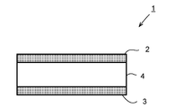
- FIG. 1 is an explanatory view showing an example of the configuration of a titanium composite material according to the present invention.
- FIG. 2 is an explanatory view showing the structure of a titanium material that is a material for hot working of a titanium composite material according to the present invention.
- FIG. 3 is an explanatory view showing a plane bending fatigue test material.
- FIG. 4 shows an example of a tissue photograph produced by the method shown in this specification.
- FIG. 5 is a schematic view of a titanium material in which titanium sponge and scrap are filled in a slab-like housing assembled from Ti—B alloy plates.
- the inventors of the present invention have made extensive studies in order to solve the above problems, and by alloying only the surface layer portion of the titanium plate of the final product, the amount of a specific alloy element that expresses the target characteristics is reduced, In addition, as a result of intensive studies to suppress the production cost of titanium material, a relatively inexpensive material such as sponge titanium is filled and sealed under reduced pressure in a case made of a titanium alloy material.
- the present inventors have found a method of hot working a titanium material to form a titanium composite material.
- a titanium composite material 1 is a titanium composite material 1 including a first surface layer portion 2, an inner layer portion 4, and a second surface layer portion 3.
- the part 2 and the second surface layer part 3 are made of a titanium alloy, and the inner layer part 4 is made of industrial pure titanium having voids.
- the corrosion resistance and other characteristics of the titanium composite material are ensured by the surface layer portions (the first surface layer portion 2 and the second surface layer portion 3) in contact with the external environment.
- the 1st surface layer part 2 and the 2nd surface layer part 3 are comprised with the titanium alloy which is excellent in various performances compared with industrial pure titanium.
- the entire titanium composite 1 has the same characteristics as a titanium material made of the same titanium alloy, but can be manufactured at a low cost.
- the 1st surface layer part 2 and the 2nd surface layer part 3 are titanium alloys as mentioned above.
- titanium alloys are generally classified into ⁇ type, ⁇ + ⁇ type and ⁇ type.
- ⁇ stabilizing element there are Al, O, N and the like as the ⁇ stabilizing element, V, Mo, Cr, Fe, Nb, Ta and the like as the ⁇ stabilizing element, and Zr, It is known that there are Sn and Hf.
- Table 1 shows elements that are known to contribute to the improvement of the characteristics by being contained in the titanium alloy.
- the titanium alloy according to the present invention is, for example, in mass%, O: 0 to 0.5%, N: 0 to 0.2%, C: 0 to 2.0%, Al: 0 to 8.0%, Sn: 0 to 10.0%, Zr: 0 to 20.0%, Mo: 0 to 25.0%, Ta: 0 to 5.0%, V: 0 to 30.0%, Nb: 0 to 40 0.0%, Si: 0 to 2.0%, Fe: 0 to 5.0%, Cr: 0 to 10.0%, Cu: 0 to 3.0%, Co: 0 to 3.0%, Ni : 0 to 2.0%, platinum group element: 0 to 0.5%, rare earth element: 0 to 0.5%, B: 0 to 5.0%, and Mn: 0 to 10.0% By containing one or more kinds exceeding 1%, a target function can be imparted to the surface of the titanium material.
- Elements that can be contained in titanium with elements other than the above are elements that are improved in strength by solid solution strengthening and precipitation strengthening (may not form a solid solution and may form precipitates) and may be contained as a common general knowledge of metal materials In some cases, the creep characteristics can be improved. Examples of these elements include elements from hydrogen (1) to astatine (85) by atomic number (excluding the noble gas elements which are Group 18 elements), and a total of about 5% is allowed.
- Impurities can be contained within a range that does not hinder the target characteristics, and other impurities mainly include impurity elements mixed from raw materials and scrap and elements mixed during production. Examples include C, N, O, Fe , H and the like are representative elements, and other elements such as Mg and Cl are mixed from raw materials, and elements such as Si, Al and S are mixed during production. If these elements are about 2% or less, it is considered that the target characteristics of the present application are not impaired.
- the titanium alloy according to the present invention is, in mass%, O: 0.01 to 0.5%, N: 0.01 to 0.2%, C: 0.01 to 2 0.0%, Al: 0.1 to 8.0%, Sn: 0.1 to 10.0%, Zr: 0.5 to 20.0%, Mo: 0.1 to 25.0%, Ta: 0.1 to 5.0%, V: 1.0 to 30.0%, Nb: 0.1 to 40.0%, Si: 0.1 to 2.0%, Fe: 0.01 to 5.
- the titanium alloy according to the present invention has O: 0.02 to 0.4%, N: 0.01 to 0.15%, C: 0.01 to 1.0%, Al: 0.2 to 6.0 %, Sn: 0.15 to 5.0%, Zr: 0.5 to 10.0%, Mo: 0.2 to 20.0%, Ta: 0.1 to 3.0%, V: 2.
- Nb 0.15-5.0%
- Si 0.1-1.0%
- Fe 0.05-2.0%
- Cr 0.2-5.0%
- Cu 0.3-2.0%
- Co 0.05-2.0%
- Ni 0.1-1.0%
- platinum group element 0.02-0.4%
- rare earth element It is more preferable to contain one or more selected from 0.001 to 0.3%, B: 0.1 to 5.0%, and Mn: 0.2 to 8.0%, and O: 0.03-0.3%, N: 0.01-0.1%, C: 0.01-0.5% Al: 0.4 to 5.0%, Sn: 0.2 to 3.0%, Zr: 0.5 to 5.0%, Mo: 0.5 to 15.0%, Ta: 0.2 to 2.0%, V: 5.0 to 20.0%, Nb: 0.2 to 2.0%, Si: 0.15 to 0.8%, Fe: 0.1 to 1.0%, Cr : 0.2-3.0%, Cu: 0.3-1.5%, Co: 0.1-1.0%, Ni: 0.1-0.8%, Platinum group element: 0.03
- JIS class 11 to JIS class 23 JIS 4600 (2012) titanium and titanium alloys—plates and strips: Contains Pd, Ru, Ni, Co, etc., and has excellent corrosion resistance and crevice corrosion resistance.
- JIS 50 JIS 4600 (2012) titanium and titanium alloy-plate and strip: Ti-1.5Al, excellent in corrosion resistance, excellent in hydrogen absorption and heat resistance.
- JIS 60 class JIS 4600 (2012) titanium and titanium alloy-plate and strip: Ti-6Al-4V, high strength and high versatility.
- JIS 61 class JIS 4600 (2012) titanium and titanium alloy-plate and strip: Ti-3Al-2.5V, good weldability and formability, and good machinability.
- JIS 80 JIS 4600 (2012) titanium and titanium alloy-plate and strip: Ti-4Al-22V, which has high strength and excellent cold workability.
- titanium alloy having a chemical component not defined in JIS other than the above can also be used.
- it is as follows. Titanium alloys having heat resistance: Ti-6Al-2Sn-4Zr-2Mo-0.08Si, Ti-6Al-5Zr-0.5Mo-0.2Si, Ti-8Al-1Mo-1V, etc.
- Low alloy and high strength titanium alloy Ti-1 to 1.5Fe-0.3 to 0.5O-0.01 to 0.04N.
- Low alloy and heat resistant titanium alloys Ti-1Cu, Ti-1Cu-0.5Nb, Ti-1Cu-1Sn-0.35Si-0.5Nb, etc. Titanium alloy having excellent creep resistance: Ti-6Al-2Sn-4Zr-6Mo, etc.
- Titanium alloys with high strength and good cold workability Ti-15V-3Cr-3Sn-3Al, Ti-20V-4Al-1Sn, etc. Titanium alloy having high strength and toughness: Ti-10V-2Fe-3Al and the like. Titanium alloy with excellent wear resistance: Ti-6Al-4V-10Cr-1.3C, etc.
- At least one of the first surface layer portion 2 and the second surface layer portion 3 contains an alloy element that exhibits target characteristics, and the balance is Ti and impurities.
- the following are illustrated as an alloy element which expresses a target characteristic, it is not this limitation.
- (D) Alloy element exhibiting hydrogen embrittlement resistance: one or more selected from Mo, V and Nb in a range of 8.0 ⁇ Mo equivalent ⁇ 20.0 (Mo equivalent Mo content (mass) %) + V content (mass%) / 1.5 + Nb content (mass%) / 3.6.
- the thickness of the surface layer portion in contact with the external environment among the first surface layer portion 2 and the second surface layer portion 3 is desirably 2 ⁇ m or more, and more desirably 5 ⁇ m or more.
- the thickness of the first surface layer portion 2 and the second surface layer portion 3 with respect to the total thickness of the titanium composite material 1 is desirably 40% or less, and more desirably 30% or less.
- the thicknesses of the first surface layer portion 2 and the second surface layer portion 3 of the titanium composite material 1 depend on the thickness of a titanium alloy material constituting the case 6 described later, and the processing rate at the time of hot processing performed thereafter. To do. For example, hot working titanium material 5 having a thickness of 75 mm using casing 6 made of titanium material having a thickness of 10 mm (hereinafter, also simply referred to as “titanium material 5”) is hot worked. When the titanium composite material 1 having a thickness of 5 mm is manufactured, the thicknesses of the first surface layer portion 2 and the second surface layer portion 3 in the titanium composite material 1 are about 667 ⁇ m, respectively. It accounts for about 13%.
- Platinum group elements 0.01-0.25%
- the platinum group element can be contained as an alloy element that has the effect of lowering the hydrogenation voltage of the titanium alloy and maintaining the natural potential in the immobile zone, and exhibits corrosion resistance. If the platinum group element content (the total content in the case of containing a plurality of platinum group elements) is less than 0.01%, the corrosion resistance will be insufficient, and if it exceeds 0.25%, the corrosion resistance will not be improved much. Not only can it not be expected, it also causes a rise in raw material costs. When a platinum group element is contained, the content is set to 0.01 to 0.25%.
- the platinum group element content is preferably 0.03% or more, more preferably 0.05% or more, preferably 0.20% or less, and 0.15% or less. More preferred.
- the platinum group element used in the present invention is useful because any element has the effect of enhancing the corrosion resistance of the titanium alloy, but it is particularly desirable to contain Pd having a high effect of improving the corrosion resistance per content. Also, relatively inexpensive Ru can be used as an alternative to Pd.
- the rare earth elements include Sc, Y, light rare earth elements (La to Eu), and heavy rare earth elements (Gd to Lu).
- the above effect can be expected when any rare earth element is added.
- the same effect can be expected when a rare earth mixture or compound such as a mixed rare earth element (Misch metal, Mm) or didymium alloy (Nd—Pr alloy) before separation and purification is used.
- the rare earth element to be added is one kind, and even if a plurality of elements are contained at the same time, it is considered that the corrosion resistance is improved by the above effect.
- the total content of rare earth elements means the total content of the above elements.
- the content when the rare earth element is contained is preferably 0.2% or less, and more preferably 0.02% or less.
- 0.001% or more of a rare earth element is contained. Is preferred.
- Co and Ni are elements that improve the corrosion resistance of the titanium alloy by changing the hydrogenation voltage, and extremely high corrosion resistance can be obtained by being added in combination with a platinum group element and / or a rare earth element.
- the Co content is 0.8% or less and the Ni content is 0.6% or less.
- the Co content is preferably 0.7% or less, and the Ni content is preferably 0.5% or less.
- both Co and Ni are preferably contained in an amount of 0.05% or more, and more preferably 0.2% or more.
- Impurities can be contained within a range not impairing the target characteristics, and other impurities are mainly impurity elements mixed from scrap such as Cr, Ta, Al, V, Cr, Nb, Si, Sn, Mn, Mo and There is Cu or the like, and together with general impurity elements C, N, Fe, O and H, a total amount of 0.5% or less is acceptable.
- the thickness of the surface layer portion in contact with the external environment among the first surface layer portion 2 and the second surface layer portion 3 is preferably 5 ⁇ m or more, and more preferably 10 ⁇ m or more.
- the thickness of the first surface layer portion 2 and the second surface layer portion 3 with respect to the total thickness of the titanium composite material 1 is desirably 40% or less, and more desirably 30% or less.
- the thicknesses of the first surface layer portion 2 and the second surface layer portion 3 of the titanium composite material 1 depend on the thickness of a titanium alloy material constituting the case 6 described later, and the processing rate at the time of hot processing performed thereafter. To do.
- a titanium composite 5 having a thickness of 5 mm is manufactured by hot-working a titanium material 5 for hot processing having a thickness of 250 mm using a casing 6 made of a titanium material having a thickness of 1 mm
- the thicknesses of the titanium alloy layers of the first surface layer portion 2 and the second surface layer portion 3 in the material 1 are each about 20 ⁇ m, and occupy about 0.4% of the total thickness of the titanium composite material 1.
- Si silicon oxide is formed on the surface layer when exposed to a high-temperature atmosphere to serve as a barrier, so that diffusion of oxygen into the titanium is suppressed and oxidation resistance is improved.
- Ti is tetravalent, while Nb is pentavalent. Therefore, when Nb is dissolved in the titanium oxide film, the vacancy concentration of oxygen in the oxide film is lowered, and the diffusion of oxygen in the oxide film is suppressed.
- the titanium composite material 1 according to the present invention contains the following various alloy elements in order to improve the oxidation resistance of at least one of the first surface layer portion 2 and the second surface layer portion 3 (at least the surface layer portion in contact with the external environment). You may let them.
- Si 0.10 to 0.60%
- Si has an action of improving the oxidation resistance at a high temperature of 600 to 800 ° C.
- the Si content is less than 0.10%, there is little allowance for improvement in oxidation resistance.
- the Si content exceeds 0.60%, the effect on the oxidation resistance is saturated, and the workability not only at room temperature but also at a high temperature is remarkably lowered. Therefore, when Si is contained, its content is set to 0.10 to 0.60%.
- the Si content is preferably 0.15% or more, more preferably 0.20% or more, preferably 0.50% or less, and more preferably 0.40% or less.
- Nb 0.1-2.0% Nb also has the effect of improving the oxidation resistance at high temperatures.
- the Nb content is 0.1% or more.
- the Nb content is preferably 0.3% or more, more preferably 0.5% or more, preferably 1.5% or less, and more preferably 1.2% or less.
- Ta 0.3 to 1.0% Ta also has the effect of improving the oxidation resistance at high temperatures.
- the Ta content is 0.3% or more.
- the Ta content is set to 0.3 to 1.0%.
- the Ta content is preferably 0.4% or more, more preferably 0.5% or more, preferably 0.9% or less, and more preferably 0.8% or less.
- Al 0.3 to 1.5%
- Al is an element that improves oxidation resistance at high temperatures.
- Al when Al is contained in a large amount, the ductility at room temperature is remarkably lowered. If the Al content is 0.3% or more, sufficient oxidation resistance is exhibited. Moreover, if the Al content is 1.5% or less, cold working can be sufficiently secured. Therefore, when Al is contained, its content is set to 0.3 to 1.5%.
- the Al content is preferably 0.4% or more, more preferably 0.5% or more, and preferably 1.2% or less.
- the oxidation resistance is improved, but by containing them in combination, the high temperature oxidation resistance can be further improved.
- one or more selected from Sn, Cu and Fe may be included.
- Sn 0 to 1.5%
- Sn is an ⁇ -phase stabilizing element and is an element that increases the high-temperature strength in the same manner as Cu. However, if the Sn content exceeds 1.5%, twin deformation is suppressed and workability at room temperature is reduced. Therefore, when it contains Sn, the content shall be 1.5% or less.
- the Sn content is preferably 1.2% or less. In order to obtain the above effect, the Sn content is preferably 0.2% or more, and more preferably 0.4% or more.
- Cu 0 to 1.5%
- Cu is an element that increases the high-temperature strength. Moreover, since it dissolves in the ⁇ phase to a certain degree, the ⁇ phase is not generated even when used at a high temperature. However, if the Cu content exceeds 1.5%, a ⁇ phase is generated depending on the temperature. Therefore, when it contains Cu, the content shall be 1.5% or less.
- the Cu content is preferably 1.4% or less, and more preferably 1.2% or less. When it is desired to obtain the above effect, the Cu content is preferably 0.2% or more, and more preferably 0.4% or more.
- Fe 0 to 0.5%
- Fe is a ⁇ -phase stabilizing element, but if it is in a small amount, the formation of ⁇ -phase is small and the oxidation resistance is not greatly affected. However, if the Fe content exceeds 0.5%, the amount of ⁇ -phase generated increases and the oxidation resistance is degraded. Therefore, when Fe is contained, the content is set to 0.5% or less.
- the Fe content is preferably 0.4% or less, and more preferably 0.3% or less.
- the total content of Sn, Cu and Fe exceeds 2.5%, the workability at room temperature is lowered, and a ⁇ phase is generated depending on the temperature. For this reason, when it contains 1 or more types selected from Sn, Cu, and Fe, it is preferable that the total content shall be 2.5% or less.
- Impurities can be contained within a range that does not hinder the target characteristics, and other impurities are mainly impurity elements such as Cr, V, Cr, Mn, and Mo as impurity elements mixed from scrap. In combination with C, N, O and H, a total amount of 5% or less is acceptable.
- the thickness of the 1st surface layer part 2 and the 2nd surface layer part 3 changes with the thickness of the raw material used for manufacture, or a subsequent processing rate, if it is 5 micrometers or more, a sufficient effect will be exhibited. Therefore, the thickness of at least one of the first surface layer portion 2 and the second surface layer portion 3 (at least the surface layer portion in contact with the external environment) is preferably 5 ⁇ m or more, and more preferably 10 ⁇ m or more. Further, the thickness of the first surface layer portion 2 and the second surface layer portion 3 with respect to the total thickness of the titanium composite material 1 is preferably 1% or more.
- the thicknesses of the first surface layer portion 2 and the second surface layer portion 3 are each desirably 100 ⁇ m or less, and more desirably 50 ⁇ m or less.
- the thicknesses of the first surface layer portion 2 and the second surface layer portion 3 with respect to the total thickness of the titanium composite material 1 are each preferably 20% or less, and more preferably 10% or less.
- the titanium composite material 1 according to the present invention contains the following various alloy elements in order to increase the fatigue resistance of at least one of the first surface layer portion 2 and the second surface layer portion 3 (at least the surface layer portion in contact with the external environment). You may let them.
- the crystal grain size of the ⁇ phase is 15 ⁇ m or less.
- the crystal grain size of the ⁇ phase is more preferably 10 ⁇ m or less, and further preferably 5 ⁇ m or less.
- the total content of Fe, Cr, Ni, Al and Zr is set to 0.08% or more.
- the total content of these elements exceeds 1.0%, ductility such as elongation or formability may be greatly reduced. Therefore, the total content of one or more selected from Fe, Cr, Ni, Al and Zr is set to 0.08 to 1.0%.
- Impurities can be contained as long as the target characteristics are not impaired, and other impurities are mainly impurity elements mixed from scrap, such as Sn, Mo, V, Mn, Nb, Si, Cu, Co, Pd, Ru, There are Ta, Y, La, Ce, and the like, and together with general impurity elements C, N, O, and H, a total amount of 5% or less is acceptable.
- the titanium composite material 1 has high fatigue strength while maintaining excellent formability, and the fatigue strength ratio (10 7 times fatigue strength / tensile strength) is 0.65 or more. The higher the fatigue strength ratio, the better the fatigue characteristics. Titanium materials generally have a numerical value of 0.5 to 0.6. It can be said that the fatigue characteristics are excellent, and if it is 0.70 or more, it is further excellent.
- the titanium composite 1 has a breaking elongation of 25% or more in the direction perpendicular to the rolling direction. In the molding process, the elongation is greatly affected, and the larger the elongation, the better the moldability.
- the thicknesses of the first surface layer portion 2 and the second surface layer portion 3 of the titanium composite material 1 depend on the thickness of a titanium alloy material constituting the case 6 described later, and the processing rate at the time of hot processing performed thereafter. To do. For example, when a titanium composite material 5 having a thickness of 5 mm is manufactured by hot-working a titanium material 5 having a thickness of 60 mm using a casing 6 made of a titanium material having a thickness of 5 mm, The thicknesses of the titanium alloy layers of the first surface layer portion 2 and the second surface layer portion 3 in the material 1 are each about 0.4 mm, and occupy about 8% of the total thickness of the titanium composite material 1.
- the layer for obtaining hydrogen absorption resistance is a titanium alloy layer containing a certain range of ⁇ -stabilizing elements.
- the reason for prescribing the formation of the ⁇ phase is that the ⁇ phase of titanium forms a hydride even at a hydrogen concentration of only a few tens of ppm, whereas the ⁇ phase of the titanium alloy can dissolve about 1000 ppm or more of hydrogen, This is because it has the characteristic that it is difficult to cause embrittlement due to hydrogen.
- ⁇ -stabilizing element such as Fe or Cr
- titanium and these elements form a compound and cause embrittlement.
- ⁇ -stabilizing elements when Mo, V, and Nb are contained in a range that satisfies “8.0 ⁇ Mo equivalent ⁇ 20.0”, the ⁇ -phase may be present even if Fe and Cr are present at the same time. Is stable and does not form a compound phase, and thus does not cause embrittlement.
- the lower limit of the Mo equivalent is the amount of alloy necessary to obtain a sufficient amount of ⁇ phase.
- the upper limit was determined because a titanium alloy with a large amount of alloy addition is not suitable for use because of its high cost. Note that the titanium alloy material used as the housing 6 does not necessarily need to be completely in the ⁇ phase, and the ⁇ phase only needs to cover the ⁇ phase even if the ⁇ phase is precipitated in the ⁇ phase.
- an existing ⁇ -type titanium alloy can be used for the case 6 described below.
- additive elements such as Cr, Sn, Al, Zr other than the above elements is allowed if the total amount is 15% or less. This is because these elements are elements included for adjusting heat treatment property, strength, and cold workability in the existing ⁇ -type titanium alloy, and do not lower the Mo equivalent defined in the present invention.
- Si, Fe and the like may be further contained.
- Impurities can be contained within a range that does not hinder the target characteristics, and other impurities include Ta, Si, Mn, and Cu as impurity elements mainly mixed from scrap, and C, which are general impurity elements, In combination with N, Fe, O and H, a total amount of 5% or less is allowed.
- the neutron beam shielding effect correlates with the thickness and processing rate of the first surface layer portion 2 and the second surface layer portion 3 with respect to the total thickness of the titanium composite material 1 described above.
- a titanium composite 5 having a thickness of 10 mm is manufactured by hot-working a titanium material 5 having a thickness of 100 mm using a casing 6 having a thickness of 20 mm
- the first surface layer portion in the titanium composite 1 The thicknesses of the titanium alloy layers of 2 and the second surface layer portion 3 are each 2 mm and occupy 20% of the total thickness of the titanium composite material 1 (40% when both surfaces are combined).
- the ratio of the alloy plate to the total thickness of the titanium material 5 may be relatively increased by reducing the thickness of the original titanium material 5 for hot working.
- B 0.1-3.0% In B, 19.9% of 10 B exists, but this 10 B has a large absorption cross section of thermal neutrons and a large shielding effect of neutron beams. If the B content is less than 0.1%, a sufficient neutron beam shielding effect cannot be obtained. If the B content exceeds 3.0%, cracking during hot rolling and deterioration of workability may occur.
- the titanium alloy containing B can be produced by adding a boride such as B or TiB 2 to titanium.
- a boride such as B or TiB 2
- a 10 B enriched boron-containing material 10 B content is approximately 90% or more
- H 3 10 BO 3 , 10 B 2 O 10 B 4 C is used, neutron beams even if the B content is small Since the shielding effect is large, it is extremely effective.
- H and O are also concentrated in the alloy layer. However, if H is removed from the material during heat treatment such as vacuum annealing, it is a problem. If O and C are 0.4 mass% O or less and 0.1 mass% C or less, which are below the upper limit contained in industrial pure titanium, they can be produced without any problem.
- Impurities can be contained within a range not impairing the target characteristics, and other impurities are mainly impurity elements mixed from scrap such as Cr, Ta, Al, V, Cr, Nb, Si, Sn, Mn, Mo and There is Cu or the like, and a total amount of 5% or less together with C, N, Fe, O, and H, which are general impurity elements, is acceptable.
- the pure titanium component of the inner layer portion 4 of the titanium composite material 1 depends on the component of the sponge titanium used when manufacturing, as will be described later.
- JIS class 1, JIS class 2, JIS class 3 or JIS class 4 industrial pure titanium can be used among the pure titanium specified in JIS. That is, it contains 0.1% or less C, 0.015% or less H, 0.4% or less O, 0.07% or less N, 0.5% or less Fe, and the balance is Ti. Pure titanium for industrial use.
- the O content of the inner layer portion of the titanium composite material can be adjusted according to desired mechanical properties, and may be contained up to a maximum of 0.4% when high strength is required. If the O content exceeds 0.4%, cracks and the like may occur, and a titanium material integrated with the surface titanium alloy after hot working may not be obtained. On the other hand, when ductility is required rather than strength, it is preferable to lower the O content, preferably 0.1% or less, more preferably 0.05% or less.
- the titanium composite material 1 according to the present invention is manufactured by hot working and cold working using a titanium material 5 described later as a raw material. At this time, the gap formed in the pure titanium portion in the titanium material 5 is pressure-bonded with the hot working and the cold working, but is not completely removed and a part remains in the inner layer portion 4. When there are too many voids in the inner layer portion 4, mechanical properties (strength and ductility) as a bulk metal are lowered.
- the shape (thickness) of the titanium composite material 1 to be manufactured is limited, which may further increase the manufacturing cost.
- the voids are contained to such an extent that the mechanical properties (strength, ductility, etc.) sufficient to maintain the structure as the titanium composite material 1 are contained, the density of the internal titanium is lowered, and thus the titanium composite material 1 is manufactured. Weight reduction of the titanium composite material 1 can be expected.
- the inner layer portion 4 is 30% or less, the inner layer portion 4, the first surface layer portion 2, and the second surface layer portion 3 are manufactured as a titanium composite material 1.
- the porosity in this case is 10% or less.
- the porosity in the inner layer portion 4 is desirably more than 0% and not more than 30%, and more desirably more than 0% and not more than 10%.
- the ratio (void ratio) of the voids remaining in the inner layer portion 4 of the titanium composite material 1 is calculated as follows. After embedding in the resin so that the cross section of the titanium material can be observed, the observation surface is buffed with a diamond or alumina suspension to give a mirror finish. An optical micrograph of the central part of the plate thickness is taken at a magnification of 500 times using the sample for observation that has been mirror-finished. The area ratio of the voids observed in the photographed optical micrograph is measured, and the 20 measurement results are averaged to calculate the void ratio.
- the microscope used for the observation is not a problem even with a normal optical microscope, but it is desirable to use it because it can be observed more clearly by using a differential interference microscope capable of observing polarized light.
- FIG. 2 is an explanatory diagram showing the structure of a hot working titanium material 5 that is a hot working material of the titanium composite 1.
- the titanium composite material 1 in which the first surface layer portion 2 and the second surface layer portion 3 are made of a titanium alloy and the inner layer portion 4 is made of pure titanium is, for example, a titanium alloy material having various characteristics as shown in FIG.
- the entire periphery is sealed to form a housing 6, and the inside of the housing 6 is filled with a titanium lump 7.
- the inside of the housing 6 is decompressed to form a titanium material 5, and this titanium material 5 is heated as a material for hot working. Manufactured by hot working. Below, the detail of each structure of a raw material is demonstrated.
- Titanium lump (chemical component) The titanium block 7 filled in the titanium material 5 for hot working according to the present invention is a normal titanium block manufactured by a smelting process such as a conventional crawl method, and the components thereof are JIS type 1, JIS type 2, JIS 3 type. Industrial pure titanium corresponding to seeds or JIS type 4 can be used.
- the titanium block 7 includes one or more selected from sponge titanium, briquettes obtained by compressing sponge titanium, and industrial pure titanium scrap.
- the size of the titanium block 7 is preferably 30 mm or less in terms of average particle size. When the average particle size is larger than 30 mm, there are problems during handling such as difficulty in handling during transportation and difficulty in placing in titanium material, resulting in poor work efficiency. Moreover, the filling rate at the time of filling in the housing
- the average particle diameter of the titanium lump 7 is 0.1 mm or more, and it is more preferable that it is 1 mm or more.
- the pure titanium powder which gave the MM (Mechanical Milling) process is a very fine powder with an average particle diameter of 0.1 mm or less.
- the MM process is a process in which powder and hard balls are put in a pot and sealed, and a pot mill is vibrated to refine the powder. Since the surface of the fine powder after MM treatment is in an active state, it is necessary to handle it by inert gasification so as not to absorb O and N in the atmosphere when recovering pure titanium powder from the pot.
- sponge titanium when using sponge titanium as a briquette by press molding, a part or all of sponge titanium may be replaced with scrap (pure titanium scrap) or titanium powder.
- housing (Chemical component)
- the titanium alloy of the alloy component described above is used so as to form a titanium alloy of the first surface layer portion 2 and the second surface layer portion 3 of the titanium composite material 1 that is the final product.
- shape Since the shape of the titanium alloy material used as the housing 6 depends on the shape of the titanium material 5 used as the hot working material, there is no particular shape, and a plate material or a tube material can be used. However, in order to provide the titanium composite 1 manufactured through the manufacturing processes such as hot working, cold working and annealing with high functionality by alloying the surface layer and excellent surface properties, The thickness of the titanium alloy material used is important.
- the housing 6 breaks during the hot working due to plastic deformation, the vacuum breaks, and the internal titanium mass 7 is oxidized. Further, the undulations of the titanium mass 7 filled in the titanium material 5 are transferred to the surface of the titanium material 5, and a large surface undulation is generated on the surface of the titanium material 5 during hot working. As a result, the mechanical properties such as surface properties and ductility of the manufactured titanium composite material 1 and further desired properties are adversely affected.
- the thickness of the titanium alloy portion in the manufactured titanium composite 1 may be locally reduced, and sufficient characteristics may not be exhibited. There is sex.
- the weight of the titanium lump 7 filled inside cannot be supported when the casing 6 becomes excessively thin, the rigidity of the titanium material 5 is insufficiently deformed during holding or processing at room temperature or hot. .
- the thickness of the titanium alloy material used for the housing 6 is 1 mm or more, hot working can be performed without causing these problems, and the titanium composite material 1 having excellent surface properties and desired characteristics can be obtained. Can be manufactured.
- the thickness of the titanium alloy material is more preferably 2 mm or more.
- the thickness of the titanium alloy material becomes too thick, the proportion of the casing 6 in the manufactured hot-working titanium material 5 increases, and the proportion of the titanium mass 7 in the titanium material 5 relatively increases. Therefore, the yield decreases and the cost increases.
- the shape of the titanium material 5 is not limited to a specific shape, but is determined by the shape of the titanium composite material 1 to be manufactured.
- a rectangular parallelepiped titanium material 5 is manufactured for the purpose of manufacturing a plate material, and a cylindrical or octagonal columnar titanium material 5 is manufactured for the purpose of manufacturing a round bar, wire or extruded material. Is done.
- the size of the titanium material 5 is determined by the size (thickness, width, length) of the product and the production amount (weight).
- a titanium lump 7 is filled in the inside of the titanium material 5 that is sealed and surrounded by the housing 6. Since the titanium mass 7 is a massive particle, there is a space (gap) between the particles. In order to improve the handleability of the titanium lump 7 and reduce these gaps, the titanium lump 7 may be previously compression-molded and then placed in the titanium material 5. If air remains in the gap in the titanium material 5, the titanium lump 7 is oxidized and nitrided during heating before hot working, and the ductility of the manufactured titanium composite material 1 is reduced. For this reason, the inside of the titanium material 5 is depressurized to a high degree of vacuum.
- the degree of vacuum inside the titanium material 5 is set to 10 Pa or less, preferably 1 Pa or less.
- the internal pressure (absolute pressure) of the titanium material 5 is greater than 10 Pa, the titanium mass 7 is oxidized or nitrided by the remaining air.
- the lower limit is not particularly defined, in order to extremely reduce the degree of vacuum, it leads to an increase in manufacturing cost such as improvement of the air tightness of the device and enhancement of the vacuum exhaust device, so it is necessary to make it less than 1 ⁇ 10 ⁇ 3 Pa Absent.
- arc welding such as TIG welding or MIG welding, electron beam welding, laser welding, or the like can be used, and the method is not particularly limited.
- the welding atmosphere is a vacuum atmosphere or an inert gas atmosphere so that the surfaces of the titanium block 7 and the housing 6 are not oxidized or nitrided.
- the titanium composite material (product) 1 is formed by performing hot working using the titanium material 5 as a hot working material.
- the hot working method can be selected depending on the shape of the product.
- a rectangular parallelepiped (slab) titanium material 5 is heated and hot-rolled to obtain a titanium plate. If necessary, after the hot rolling, the surface oxide layer may be removed by pickling or the like after hot rolling, and then cold rolling may be performed to further reduce the thickness.
- a cylindrical or polygonal (billet) titanium material 5 is heated and hot-rolled or hot extruded to form a titanium round bar or wire. Further, as necessary, after the hot working, the oxide layer may be removed by pickling or the like, and then cold-rolled and further thinned as in the conventional process.
- a cylindrical or polygonal (billet) titanium material 5 is heated and subjected to hot extrusion to obtain various cross-sectional titanium profiles.
- the heating temperature before hot working may be the same heating temperature as when hot working a normal titanium slab or billet. Although it varies depending on the size of the titanium material 5 or the degree of hot working (working rate), it is preferably set to 600 ° C. or more and 1200 ° C. or less. If the heating temperature is too low, the high-temperature strength of the titanium material 5 becomes too high, causing cracks during hot working, and joining of the titanium block 7 and the casing (titanium alloy part) 6 becomes insufficient. On the other hand, if the heating temperature is too high, the structure of the obtained titanium composite material 1 becomes rough, so that sufficient material properties cannot be obtained, and the surface casing (titanium alloy portion) 6 is thinned by oxidation. End up. If the heating temperature is 600 to 1200 ° C., hot working can be performed without such a problem.
- the degree of processing during hot processing can be selected to control the porosity in the titanium composite 1.
- the processing rate here is a ratio (percentage) obtained by dividing the difference between the cross-sectional area of the titanium material 5 and the cross-sectional area of the titanium composite material 1 after hot working by the cross-sectional area of the titanium material 5.
- the gap between the titanium masses 7 inside the titanium material 5 is not sufficiently crimped, and therefore remains as a void after hot working.
- the titanium composite material 1 containing many such voids is lighter by the amount of voids contained.
- the mechanical properties are not sufficiently exhibited.
- the porosity decreases and the mechanical properties improve. For this reason, when the mechanical characteristics of the titanium composite material 1 to be manufactured are regarded as important, a higher processing rate is preferable.
- the processing rate is 90% or more, the gap between the grain boundaries of the titanium mass 7 inside the titanium material 5 can be sufficiently bonded, and the voids of the titanium composite material 1 can be reduced.
- a higher processing rate is preferable in order to surely eliminate the voids in the titanium composite material 1, but the cross-sectional area of the titanium material 5 must be increased, and hot processing must be repeated many times. No longer.
- the processing rate is preferably 99.9% or less.
- the titanium material When producing the titanium material, first, five titanium plates were temporarily assembled into a box shape, and then sponge titanium was filled therein, and the opening of the temporarily assembled box was covered with a titanium plate. In some titanium materials, briquette-shaped sponge titanium (sponge briquette) or a mixture of sponge titanium and pure titanium scrap to form briquettes was used instead of sponge titanium.
- the temporarily assembled titanium material was put in a vacuum chamber and decompressed (vacuum) until a predetermined pressure was reached, and then the seam of the casing was welded and sealed with an all-around electron beam. The degree of vacuum in the chamber at this time was 8.7 ⁇ 10 ⁇ 3 to 7.6 ⁇ 10 ⁇ 2 Pa as shown in Table 2.
- Titanium material For some titanium materials (Test Nos. 16 and 17 in Table 2), one case was prepared by drilling a hole in the center of the plate and TIG welding a titanium tube with an inner diameter of 6 mm. Titanium material was temporarily assembled so that it might become an end surface.
- the temporarily assembled titanium material is welded with an electron beam all around, and then the inside of the titanium material is reduced to a predetermined degree of vacuum (6.9 ⁇ 10 ⁇ 1 to 1.2 Pa) through a titanium tube. Later, the titanium tube was crimped to maintain the vacuum inside the titanium material.
- the manufactured titanium material was heated to 850 ° C. in an air atmosphere and then hot-rolled to obtain a hot-rolled sheet having a thickness of 5 mm. Thereafter, descaling was performed on both the front and back surfaces using shot blasting and nitric hydrofluoric acid. Further, cold rolling is performed to obtain a titanium plate having a thickness of 1 mm, and annealing is performed by heating to 600 to 750 ° C. in a vacuum or an inert gas atmosphere and holding for 240 minutes to perform the test of the present invention. A material was prepared.
- a test piece having a thickness of 1 mm, a width of 30 mm, and a length of 40 mm was cut out from the hot-rolled sheet and coated with an anticorrosion tape so that the cut surface and the surface to which the corrosion-resistant titanium alloy plate was not attached were not exposed to a corrosive environment.
- the corrosion rate was calculated from the weight change before and after the corrosion test.
- the manufactured titanium composite material was embedded in a resin so that the cross section could be observed, polished and corroded, and then observed with an optical microscope to measure the thickness of the surface layer titanium alloy layer.
- the measured thickness of the surface layer titanium alloy layer was divided by the total thickness of the titanium composite material, and calculated as the ratio of the surface layer.
- void ratio the ratio of voids remaining in the pure titanium portion of the titanium composite (hereinafter referred to as void ratio)
- void ratio the ratio of voids remaining in the pure titanium portion of the titanium composite
- polishing and mirror finishing after filling the resin so that the sample cross-section can be observed, polishing and mirror finishing, and then optical microscopy at a magnification of 500 times I took a picture.
- the area ratio of the voids was calculated from the photographed optical micrograph, and the five measurement results were averaged to calculate the void ratio.
- the surface properties of the manufactured titanium composite were evaluated by the presence or absence of wrinkles in visual observation.
- a commercially available pure titanium JIS 1-3
- a corrosion-resistant titanium alloy Ti-0.06% Pd, ASTM Gr17 1 mm plate material were used to perform the above-described corrosion test. Went.
- Test No. is a comparative example.
- 1-4 are commercially available pure titanium materials (JIS 1 to 3 types) and corrosion resistant titanium materials (Ti-0.06Pd, ASTM Gr. 17), respectively, manufactured through melting, decomposition, and forging processes. These results serve as an index for evaluating the performance of the titanium composite of the present invention described later.
- Test No. 18 and 19 are titanium composite materials manufactured by using a pure titanium scrap-containing sponge briquette using pure titanium scrap as a part of the sponge briquette or sponge titanium as pure titanium inside the titanium material. These have excellent corrosion resistance equivalent to that of the corrosion-resistant titanium alloy, as in the case where sponge titanium is used inside.
- a titanium alloy thickness: 10 mm
- the titanium material When producing the titanium material, first, five titanium plates were temporarily assembled into a box shape, and then sponge titanium was filled therein, and the opening of the temporarily assembled box was covered with a titanium plate. The temporarily assembled titanium material was put in a vacuum chamber, and the pressure was reduced to 8.7 ⁇ 10 ⁇ 3 Pa. Then, the joint of the casing was welded with an all-around electron beam and sealed.
- the manufactured titanium material was heated to 850 ° C. in an air atmosphere and then hot-rolled to obtain a hot-rolled sheet having a thickness of 5 mm.
- a test piece having a thickness of 5 mm, a width of 30 mm, and a length of 40 mm was cut out from the test material, and thereafter, the same evaluation as in Example 1-1 was performed.
- the above-mentioned corrosion test was performed using a commercially available pure titanium (JIS class 1) and a corrosion-resistant titanium alloy (Ti-0.06% Pd, ASTM Gr17) 5 mm plate material. It was.
- Reference numerals 20 to 23 are commercially available corrosion-resistant titanium materials manufactured through a melting / decomposing / forging process, and these results serve as indexes for evaluating the performance of the titanium composite material according to the present invention described later.
- Test No. No. 28 is provided with excellent corrosion resistance by containing platinum group elements Pd and Ru in the surface layer titanium alloy.
- Test No. Nos. 31 to 41 have excellent corrosion resistance because the surface layer titanium alloy contains rare earth elements Y, Dy, La, didymium, Pr, Ce, and Mm in addition to platinum group elements Pd and Ru. Has been.
- the surface layer titanium alloy contains Nd and Sm, which are rare earth elements, in addition to Pd, which is a platinum group element, and further has excellent corrosion resistance by containing Co.
- the surface layer titanium alloy is provided with excellent corrosion resistance by containing Ni in addition to Ru which is a platinum group element.
- Test No. No. 46 is provided with excellent corrosion resistance because the surface layer titanium alloy contains Y, which is a rare earth element, in addition to Pd, which is a platinum group element, and Ni.
- test no. In No. 48 excellent corrosion resistance is imparted by adding rare earth elements Y, Co, and Ni to the surface layer titanium alloy in addition to platinum group element Pd.
- the titanium material When producing the titanium material, first, five titanium plates were temporarily assembled into a box shape, and then sponge titanium was filled therein, and the opening of the temporarily assembled box was covered with a titanium plate. The temporarily assembled titanium material was put in a vacuum chamber, and the pressure was reduced to 8.7 ⁇ 10 ⁇ 3 Pa. Then, the joint of the casing was welded with an all-around electron beam and sealed.
- the produced titanium material was heated to 850 ° C. in an air atmosphere and then hot-rolled to obtain a hot-rolled sheet having a thickness of 20 mm.
- the obtained hot-rolled pickled plate was subjected to vacuum annealing at 725 ° C., and then subjected to shot blasting and pickling finish using nitrous acid to obtain a titanium composite material.
- a test piece having a thickness of 20 mm, a width of 50 mm and a length of 50 mm was cut out from the test material, and thereafter, the same evaluation as in Examples 1-1 and 1-2 was performed.
- titanium block 7 one or more selected from briquette, scrap and sponge titanium
- the titanium material 5 was heated to 820 ° C. and hot-rolled to a thickness of 5 mm, and then descaling treatment was performed on both the front and back surfaces using shot blasting and nitric hydrofluoric acid.
- a heat treatment was performed by heating to 600 to 750 ° C. in a vacuum or an inert gas atmosphere and holding for 240 minutes.
- the inner layer portion 4 is an industrial pure titanium JIS type 2 and does not have the first surface layer portion 2 and the second surface layer portion 3. Therefore, the increase in oxidation at 200 ° C. heating at 700 ° C. is 40 g / m 2 or more, and the increase in oxidation at 200 ° C. heating at 750 ° C. is 100 g / m 2 or more.
- the inner layer portion 4 is made of industrial pure titanium JIS type 1
- the first surface layer portion 2 and the second surface layer portion 3 contain Si, and have a sufficient thickness of 5 ⁇ m or more. Therefore, the oxidation increase in heating at 700 ° C. for 200 hours is 25 g / m 2 or less, and the oxidation increase in heating at 750 ° C. for 200 hours is 70 g / m 2 or less, indicating excellent oxidation resistance.
- the porosity is less than 1%, and the mechanical properties are also good.
- the inner layer part 4 is made of industrially pure titanium JIS type 2
- the first surface layer part 2 and the second surface layer part 3 contain Si, and have a sufficient thickness of 5 ⁇ m or more. Therefore, the oxidation increase in heating at 700 ° C. for 200 hours is 25 g / m 2 or less, and the oxidation increase in heating at 750 ° C. for 200 hours is 70 g / m 2 or less, indicating excellent oxidation resistance.
- the porosity is less than 1%, and the mechanical properties are also good.
- the inner layer portion 4 is made of industrially pure titanium JIS type 3, the first surface layer portion 2 and the second surface layer portion 3 contain Si, and have a sufficient thickness of 5 ⁇ m or more. Therefore, the oxidation increase in heating at 700 ° C. for 200 hours is 25 g / m 2 or less, and the oxidation increase in heating at 750 ° C. for 200 hours is 70 g / m 2 or less, indicating excellent oxidation resistance. Also, the porosity is less than 1%, and the mechanical properties are also good.
- the inner layer part 4 is of industrial pure titanium JIS type 2, and the first surface layer part 2 and the second surface layer part 3 contain one or more selected from Si, Nb, Ta, Al, and the thickness thereof. Has a sufficient thickness of 5 ⁇ m or more. Therefore, the oxidation increase in heating at 700 ° C. for 200 hours is 25 g / m 2 or less, and the oxidation increase in heating at 750 ° C. for 200 hours is 70 g / m 2 or less, indicating excellent oxidation resistance. Also, the porosity is less than 1%, and the mechanical properties are also good.
- Example 2-2 Test No. in Table 6 In Nos. 19 and 20, a housing 6 having a thickness of 50 mm, a width of 1000 mm, and a length of 4000 mm made of a titanium alloy plate containing Nb was prepared, and then a titanium block 7 made of industrial pure titanium (briquette and sponge titanium). ) And sealed in a vacuum atmosphere of about 8 ⁇ 10 ⁇ 2 Pa to obtain a titanium material 5 as a hot rolling material.
- the titanium material 5 was heated to 820 ° C. and hot-rolled to a thickness of 20 mm, and then descaling treatment was performed on both the front and back surfaces using shot blasting and nitric hydrofluoric acid. Further, as an annealing treatment, a heat treatment was performed by heating to 600 to 700 ° C. in a vacuum or an inert gas atmosphere and holding for 240 minutes.
- the inner layer portion 4 is an industrial pure titanium JIS type 2, and the first surface layer portion 2 and the second surface layer portion 3 are made of a titanium alloy containing Nb. Moreover, the porosity of the inner layer part 4 is also less than 30%. Furthermore, the thickness of the 1st surface layer part 2 and the 2nd surface layer part 3 also has sufficient thickness with 5 micrometers or more. Therefore, the oxidation increase in heating at 700 ° C. for 200 hours is 25 g / m 2 or less, and the oxidation increase in heating at 750 ° C. for 200 hours is 70 g / m 2 or less, indicating excellent oxidation resistance.
- test no. No. 21 is a titanium alloy plate made of Ti-1.0Cu-1.0Sn-0.35Si-0.25Nb
- No. 21 No. 22 is a titanium alloy plate made of Ti-1.0Cu-0.5Nb
- No. 22 A titanium alloy plate made of Ti-0.25Fe-0.45Si is used for 23, and a case 6 having a thickness of 250 mm, a width of 1000 mm, and a length of 4500 mm is produced, and then a titanium block 7 made of industrial pure titanium is used. (Briquette and sponge titanium) were filled and sealed in a vacuum atmosphere of about 8 ⁇ 10 ⁇ 2 Pa to obtain a titanium material 5, which was a material for hot rolling.
- a descaling process was performed to remove about 40 ⁇ m per side (80 ⁇ m on both sides) on both sides using shot blasting and nitric hydrofluoric acid.
- a heat treatment was performed by heating to 600 to 700 ° C. in a vacuum or an inert gas atmosphere and holding for 240 minutes.
- the first surface layer portion 2 and the second surface layer portion 3 contain one or more of Si and Nb. Moreover, the porosity of the inner layer part 4 is as low as less than 0.1%. Furthermore, the thickness of the 1st surface layer part 2 and the 2nd surface layer part 3 also has sufficient thickness with 5 micrometers or more. Therefore, the oxidation increase in heating at 700 ° C. for 200 hours is 25 g / m 2 or less, and the oxidation increase in heating at 750 ° C. for 200 hours is 70 g / m 2 or less, indicating excellent oxidation resistance.
- Example 3-1 As shown in FIGS. 1 and 2, a titanium alloy plate 6 was filled with a titanium block 7 to form a titanium material 5, and a method of rolling the titanium material 5 was performed to prepare a test piece.
- the total thickness of the titanium material 5 is 125 mm, the total content of Fe, Cr, Ni, Al, and Zr in the casing 6 is 0.03 to 1.1%, and the chemical composition of the inner titanium mass 7 is O : 0.030 to 0.33%, Fe: 0.028 to 0.086%, C: 0.01% or less, H: 0.003 or less, N: 0.006% or less.
- titanium materials 5 having a total thickness of 25 mm and 50 mm were also produced.
- a casing 6 is produced on the outer periphery using a titanium alloy plate having an adjusted Fe, Cr, Ni, Al, Zr concentration and thickness, and sponge titanium is compression-molded inside the casing 6.
- the compressed body (briquette) was filled, and then the lid of the titanium material 5 was welded.
- a briquette is prepared by mixing 10% or 30% of a titanium material 5 that is not filled with briquettes and filled with sponge titanium as it is, a pure titanium plate having the same composition as sponge titanium, and cut to about 25 mm square. A filled titanium material 5 was produced.
- test material which is titanium composite material 1, (alpha) phase crystal grain diameter in each position, tensile strength, elongation, fatigue strength, and the moldability were evaluated on the conditions shown below.
- the thickness of the 1st surface layer part 2 and the 2nd surface layer part 3 was measured by EPMA.
- the average crystal grain size of the ⁇ phase at the position of 1 to 10% of the plate thickness was calculated in the inner layer portion and the surface layer portion by a cutting method according to JIS G 0551 (2005).
- a ball head overhang test was performed on a titanium plate processed into a 90 mm ⁇ 90 m ⁇ 0.5 mm shape using a ball head punch of ⁇ 40 mm in a deep drawing tester manufactured by Tokyo Tester, model number SAS-350D.
- the overhang test is performed by applying high viscosity oil (# 660) manufactured by Nippon Tool Oil Co., Ltd., placing a poly sheet on it, preventing the punch and titanium plate from touching directly, and the overhang height when the test material breaks. It was evaluated by comparing the thickness.
- the overhang height in the ball head overhang test is strongly affected by the oxygen concentration, so that the moldability is 21.0 mm or more for JIS type 1, 19.0 mm or more for JIS type 2 and 13.0 mm or more for JIS type 3 ( (Circle mark in the table). In the case of less than this, it was considered unsatisfactory (x mark in the table).
- FIG. 4 shows an example of a tissue photograph when produced by the above method. 4 (a) shows test no. 1 (comparative example, general titanium material), and FIG. 5 (example of the present invention), and FIG. 12 (Example of the present invention), and FIG. 17 is a structure photograph of 17 (example of the present invention)
- 4 (b) to 4 (d) are examples of the present invention, and the thicknesses of the first surface layer portion 2 and the second surface layer portion 3 are different.
- Table 8 shows the case where industrial pure titanium corresponding to JIS type 1 is used as the titanium mass 7
- Table 9 shows the case where industrial pure titanium corresponding to JIS 2 and 3 type is used as the titanium mass 7.
- symbols N1 to N4 in the column of “Level of material form used inside the casing” indicate the following types and ratios.
- N1 Briquette using 100% sponge titanium
- N2 100% titanium sponge remains
- N3 Briquette mixed with 90% sponge titanium and 10% scrap with the same composition
- N4 Briquette mixed with 70% sponge titanium and 30% scrap with the same composition
- Test No. in Table 8 Nos. 4 to 33 are examples of the present invention that satisfy all the conditions specified in the present invention. 1 to 3 are comparative examples that do not satisfy the conditions defined in the present invention.
- Test No. 1 to 3 are titanium alloy plates corresponding to JIS Class 1, and have formability and fatigue strength which are standards for evaluating the formability and fatigue strength of the examples of the present invention.
- Test No. The fatigue strength ratios of 1 to 3 are 0.63, 0.63, and 0.55, respectively, which are typical values.
- Test No. in Table 9 36 to 43 and 46 to 53 are examples of the present invention that satisfy all of the conditions defined in the present invention.
- Reference numerals 34, 35, 44 and 45 are comparative examples which do not satisfy the conditions defined in the present invention.
- Test No. Nos. 34 and 35 are titanium alloy plates corresponding to JIS class 2, and test nos. 44 and 45 are JIS type 3 equivalent titanium alloy plates. Test No. Each of 34, 35, 44 and 45 has formability and fatigue strength which are standards for evaluating the formability and fatigue strength of the examples of the present invention. Test No. The fatigue strength ratios of 34 and 35 are 0.58 and 0.59, respectively. The fatigue strength ratios of 44 and 45 are 0.59 and 0.58, respectively. Both are general values.
- a ⁇ -type titanium alloy Ti-15V-3Cr-3Sn-3Al plate material thickness 1 to 15 mm
- a case sealed with a ⁇ -type titanium alloy is formed, the inside of the case is filled with sponge titanium, and the inside of the titanium material is depressurized to a predetermined degree of vacuum. It was.
- the produced casing was heated to 850 ° C. in an air atmosphere, and then hot-rolled at a processing rate of 92 to 97% as shown in Table 10 to obtain a hot rolled sheet having a thickness of 4.8 to 5.0 mm. did.
- annealing was performed in a vacuum atmosphere at 600 to 650 ° C. for 4 to 10 hours. Furthermore, shot blasting and pickling were performed to remove the scale layer.
- the manufactured titanium composite was embedded in a resin so that the cross-section could be observed, polished and corroded, and then observed with an optical microscope to measure the thickness of the surface layer.
- the measured thickness of the surface layer portion was divided by the total thickness of the titanium composite material, and the ratio of the surface layer portion was calculated.
- void ratio the ratio of voids remaining in the pure titanium portion of the titanium composite
- the titanium composite material of the present invention and each titanium plate of the comparative example were exposed at 500 ° C. for 5 hours in a 1% by volume H 2 + 99% by volume Ar atmosphere as a hydrogen absorption environment.
- Reference numeral 1 is an example of an industrial pure titanium type 2 material manufactured without using a casing.
- the impact value is as low as less than 2.0 ⁇ 10 2 J / cm 2 due to exposure to a hydrogen environment.
- Example 4-2 An example in which the alloy type of the housing is changed with respect to Example 4-1.
- the thickness of the titanium plate used for the casing was 3 mm, the total thickness of the titanium material was 60 mm, and the thickness after hot rolling was 4.8 to 5.0 mm.
- Other sample preparation was the same as in Example 4-1. It was done by the method. Table 11 shows an example.
- Test No. 7 to 9 satisfied the definition of the present invention, and the impact value was as high as 2.0 ⁇ 10 2 J / cm 2 or higher.
- Example 4-3 An example in which the type of sponge titanium to be filled is changed to JIS 3 for Example 4-1.
- the thickness of the titanium plate used for the casing was 3 mm, the total thickness of the titanium material was 60 mm, and the thickness after hot rolling was 4.8 to 5.0 mm.
- Other sample preparation was the same as in Example 4-1. It was done by the method.
- the impact value of JIS3 type used here was 0.5 ⁇ 10 2 J / cm 2 , and 0.4 ⁇ 10 2 J / cm 2 or less, which was reduced by 20% or more from that, was determined as hydrogen embrittlement. .
- Table 12 shows an example.
- Reference numeral 10 is an example of industrial pure titanium type 3 material manufactured without using a casing.
- the impact value is as low as less than 0.5 ⁇ 10 2 J / cm 2 due to exposure to a hydrogen environment.
- No. No. 11 satisfied the regulation of the present invention, and the impact value was as high as 0.5 ⁇ 10 2 J / cm 2 .
- Example 5-1 Test No. shown in Table 13 The neutron beam shielding plates 1 to 24 are manufactured by the following method.
- the Ti—B alloy plate of the housing 6 is made of an ingot in which B is added and dissolved in advance by TiB 2 or 10 B enriched boron (H 3 10 BO 3 , 10 B 2 O 10 B 4 C). It was produced by hot rolling. After hot rolling, a continuous pickling line made of nitric hydrofluoric acid was passed through to remove the oxide scale on the surface of the hot rolled sheet.
- the Ti—B alloy plate was welded to the position corresponding to the five surfaces of the slab by electron beam welding in a vacuum atmosphere of about 8 ⁇ 10 ⁇ 3 Pa to produce a hollow housing 6. .
- One or more kinds selected from sponge titanium, briquettes compressed with sponge titanium, and titanium scrap finely cut to 30 mm ⁇ 30 mm ⁇ 30 mm or less are put in the housing 6, and the remaining one surface is similarly electron beam welded. As a result, a titanium material 5 having a vacuum of 100 mm thickness was produced.
- the ratio of the surface layer part to the total thickness of the hot-rolled sheet can be adjusted by changing the thickness of the alloy sheet.
- FIG. 5 is a schematic view of the titanium material 5 in which the titanium block 7 is filled in the slab-like housing 6 assembled with the Ti—B alloy plates as described above.
- the titanium material 5 was heated at 800 ° C. for 240 minutes using a steel facility, and then hot-rolled to produce a strip coil having a thickness of about 4 to 20 mm.
- the strip-like coil after hot rolling was passed through a continuous pickling line made of nitric hydrofluoric acid, and was cut by about 50 ⁇ m per side, and then the state of occurrence of cracks was visually observed.
- the measuring method of the depth of the surface layer part (B-concentrated layer) is a part of the hot-rolled sheet after pickling (sampled from the center part in the width direction for each of the three parts of the front end, the center and the rear end in the longitudinal direction). ) was cut and subjected to SEM / EDS analysis to determine the ratio of the surface layer part to the plate thickness and the B content of the surface layer part (the average value in the observed part was adopted).
- a total of 20 bending specimens in the L direction were collected from the central part in the width direction at three points, the front, center and rear ends in the longitudinal direction, and bent according to JIS Z 2248 (metal material bending test method).
- JIS Z 2248 metal material bending test method
- a specimen having a thickness of 500 mm ⁇ 500 mm ⁇ 4 to 20 mm was fixed at a position of 200 mm from the radiation source using Am-Be (4.5 MeV) as a radiation source.
- the detector is installed at a position 300 mm from the radiation source, and the peak value of the target energy is measured for each of the radiation equivalents of the control specimen, industrial pure titanium JIS type 1 (4 mm thickness) and the specimen (4-20 mm thickness). Then, the neutron beam shielding effect was evaluated from the ratio of the values (the value of each test piece was described with the neutron beam shielding effect of industrial pure titanium JIS type 1 as 1).
- Test No. The comparative examples 1 to 10 and the example of the present invention are cases where the base material type is pure titanium JIS type 1.
- Test No. 1 which is a comparative example, is a case where pure titanium for industrial use not containing B is used as the casing 6 instead of the Ti—B alloy plate. No cracks occurred in the hot-rolled sheet, and no cracks occurred in the bending test.
- Test No. as an example of the present invention. 2 is a case where the 100 mm-thick titanium material 5 is hot-rolled to a thickness of 20 mm. Since the ratio of the first surface layer part 2 and the second surface layer part 3 is 5% and the B content in the first surface layer part 2 and the second surface layer part 3 is 0.5%, both are hot-rolled sheets No cracks occurred in the case, and no cracks occurred in the bending test.
- Test No. 3 to 7 are cases in which the titanium material 5 having a thickness of 100 mm was hot-rolled to a thickness of 10 mm, and the ratio, B content, and porosity of the first surface layer portion 2 and the second surface layer portion 3 were changed.
- the ratio of the first surface layer portion 2 and the second surface layer portion 3 is in the range of 5 to 40%, and the B content in the first surface layer portion 2 and the second surface layer portion 3 is 0.1 to 3.0%. Therefore, no crack was generated in the hot-rolled sheet, and no crack was generated in the bending test.
- Test No. Nos. 8 to 10 are cases where the titanium material 5 having a thickness of 100 mm was hot-rolled to a thickness of 4 mm, and the ratio of the first surface layer portion 2 and the second surface layer portion 3 and the B content were changed.
- the ratio of the first surface layer portion 2 and the second surface layer portion 3 is in the range of 5 to 40%, and the B content in the first surface layer portion 2 and the second surface layer portion 3 is 0.1 to 3.0%. Therefore, no crack was generated in the hot-rolled sheet, and no crack was generated in the bending test.
- Test No. The examples of the present invention shown in 11 to 17 are cases in which the base material is made of two types of pure titanium JIS.
- Test No. 11 is the case where the 100 mm-thick titanium material 5 is hot-rolled to a thickness of 20 mm.
- the ratio of the first surface layer portion 2 and the second surface layer portion 3 is in the range of 5 to 40%, and the B content in the first surface layer portion 2 and the second surface layer portion 3 is 0.1 to 3.0%. Therefore, no crack was generated in the hot-rolled sheet, and no crack was generated in the bending test.
- Test No. Nos. 12 to 14 are cases where the titanium material 5 having a thickness of 100 mm was hot-rolled to a thickness of 10 mm and the ratio or B content of the first surface layer portion 2 and the second surface layer portion 3 was changed.
- the ratio of the first surface layer portion 2 and the second surface layer portion 3 is in the range of 5 to 40%, and the B content in the first surface layer portion 2 and the second surface layer portion 3 is 0.1 to 3.0%. Therefore, no crack was generated in the hot-rolled sheet, and no crack was generated in the bending test.
- Test No. 15 to 17 are cases in which the titanium material 5 having a thickness of 100 mm is hot-rolled to a thickness of 4 mm and the ratio or B content of the first surface layer portion 2 and the second surface layer portion 3 is changed.
- the ratio of the first surface layer portion 2 and the second surface layer portion 3 is in the range of 5 to 40%, and the B content in the first surface layer portion 2 and the second surface layer portion 3 is 0.1 to 3.0%. Therefore, no crack was generated in the hot-rolled sheet, and no crack was generated in the bending test.
- Test No. Examples 18 to 24 of the present invention are cases where the base material is made of three types of pure titanium JIS.
- Test No. 18 is a case where the 100 mm-thick titanium material 5 is hot-rolled to a thickness of 20 mm.
- the ratio of the first surface layer portion 2 and the second surface layer portion 3 is in the range of 5 to 40%, and the B content in the first surface layer portion 2 and the second surface layer portion 3 is 0.1 to 3.0%. Therefore, no crack was generated in the hot-rolled sheet, and no crack was generated in the bending test.
- Test No. Nos. 19 to 21 are cases where the titanium material 5 having a thickness of 100 mm is hot-rolled to a thickness of 10 mm, and the ratio or B content of the first surface layer portion 2 and the second surface layer portion 3 is changed.
- the ratio of the first surface layer portion 2 and the second surface layer portion 3 is in the range of 5 to 40%, and the B content in the first surface layer portion 2 and the second surface layer portion 3 is 0.1 to 3.0%. Therefore, no crack was generated in the hot-rolled sheet, and no crack was generated in the bending test.
- Test No. 22 to 24 are cases in which the titanium material 5 having a thickness of 100 mm was hot-rolled to a thickness of 4 mm, and the ratio or B content of the first surface layer portion 2 and the second surface layer portion 3 was changed.
- the ratio of the first surface layer portion 2 and the second surface layer portion 3 is in the range of 5 to 40%, and the B content in the first surface layer portion 2 and the second surface layer portion 3 is 0.1 to 3.0%. Therefore, no crack was generated in the hot-rolled sheet, and no crack was generated in the bending test.
- test No. which is a comparative example.
- the neutron beam shielding effect could not be confirmed. From 2 to 24, in any case, the neutron shielding effect was 1 or more, and the neutron beam shielding effect could be confirmed.
- the neutron shielding effect is 23.7 in the stainless steel plate (4 mm thickness) whose B content used for the nuclear fuel storage rack is 0.5%.
- Test No. Nos. 4 to 7, 10, 13, 14, 17, 20, and 21 had a higher neutron beam shielding effect than this stainless steel plate.
- Example 5-1 In the same procedure as in Example 5-1, a Ti-B casing 6 having a different plate thickness and chemical composition was combined, and a 100 mm thick titanium material 5 filled with sponge titanium and cut scraps was produced.
- the titanium material 5 was heated at 800 ° C. for 240 minutes using a steel facility, and then hot-rolled to produce a strip coil having a thickness of about 5 mm.
- the strip-shaped coil after hot rolling passes through a continuous pickling line made of nitric hydrofluoric acid, and further performs cold rolling to form a titanium plate having a thickness of 1 mm, and as an annealing treatment in a vacuum or an inert gas atmosphere.
- a heat treatment was performed by heating to 600 to 750 ° C. and holding for 240 minutes to obtain a titanium composite material 1.
- the measuring method of the depth of the 1st surface layer part 2 and the 2nd surface layer part 3 (B concentrating layer) is a part about titanium composite material 1 (longitudinal direction front-end
- SEM / EDS analysis is performed on each of the polished and polished portions, and the ratio of the first surface layer portion 2 and the second surface layer portion 3 to the plate thickness of the titanium composite material 1 and the first surface layer portion 2 and the second surface layer portion.
- the B content of the second surface layer part 3 was determined (an average value in the observed part was adopted).
- a total of 20 bending specimens in the L direction were collected from the central part in the width direction at three points, the front, center and rear ends in the longitudinal direction, and bent according to JIS Z 2248 (metal material bending test method).
- JIS Z 2248 metal material bending test method
- a specimen having a thickness of 500 mm ⁇ 500 mm ⁇ 1 mm was fixed at a position 200 mm from the radiation source using Am-Be (4.5 MeV) as a radiation source.
- the detector is installed at a position 300 mm from the radiation source, and the peak value of the target energy is measured for each of the radiation equivalents of the industrial test pure titanium JIS type 1 (1 mm thickness) and the test piece (1 mm thickness). From the ratio of the values, the neutron beam shielding effect was evaluated (the value of each test piece was described with the neutron beam shielding effect of 1 type of industrial pure titanium JIS being 1).
- Test No. The comparative examples 25 to 28 and the examples of the present invention are cases in which the type of the base material is pure titanium JIS type 1.
- Test No. 25 which is a comparative example, is a case where pure titanium for industrial use containing no B is used as the casing 6 instead of the Ti—B alloy plate.
- the cold-rolled sheet did not crack and did not crack in the bending test.
- Test No. as an example of the present invention. 26 to 28 are cases where the ratio, B content, and porosity of the first surface layer portion 2 and the second surface layer portion 3 were changed.
- the ratio of the first surface layer portion 2 and the second surface layer portion 3 is in the range of 5 to 40%, and the B content in the first surface layer portion 2 and the second surface layer portion 3 is 0.1 to 3.0%. Therefore, no cracks occurred in the cold-rolled sheet, and no cracks occurred in the bending test.
- Test No. Examples 29 to 31 of the present invention are cases in which the base material type is pure titanium JIS type 2, and the ratio, B content, and porosity of the first surface layer portion 2 and the second surface layer portion 3 are changed.
- the ratio of the first surface layer portion 2 and the second surface layer portion 3 is in the range of 5 to 40%, and the B content in the first surface layer portion 2 and the second surface layer portion 3 is 0.1 to 3.0%. Therefore, no cracks occurred in the cold-rolled sheet, and no cracks occurred in the bending test.
- Examples of the present invention of 32 to 34 are cases where the base material is made of pure titanium JIS 3 and the ratio, B content, and porosity of the first surface layer portion 2 and the second surface layer portion 3 are changed.
- the ratio of the first surface layer portion 2 and the second surface layer portion 3 is in the range of 5 to 40%, and the B content in the first surface layer portion 2 and the second surface layer portion 3 is 0.1 to 3.0%. Therefore, no cracks occurred in the cold-rolled sheet, and no cracks occurred in the bending test.
- test No. which is a comparative example. 25
- the neutron beam shielding effect could not be confirmed.
- 26 to 34 in any case, the neutron shielding effect was 1 or more, and the neutron beam shielding effect could be confirmed.
- Titanium composite material First surface layer part3. Second surface layer 4. Inner layer part 5. 5. Titanium material for hot working Case 7. Titanium lump
Landscapes
- Engineering & Computer Science (AREA)
- Mechanical Engineering (AREA)
- Chemical & Material Sciences (AREA)
- Materials Engineering (AREA)
- Metallurgy (AREA)
- Organic Chemistry (AREA)
- Physics & Mathematics (AREA)
- Thermal Sciences (AREA)
- Crystallography & Structural Chemistry (AREA)
- Laminated Bodies (AREA)
- Metal Rolling (AREA)
- Wrappers (AREA)
- Manufacture And Refinement Of Metals (AREA)
- Other Surface Treatments For Metallic Materials (AREA)
- Powder Metallurgy (AREA)
Priority Applications (7)
| Application Number | Priority Date | Filing Date | Title |
|---|---|---|---|
| JP2016567887A JP6172405B2 (ja) | 2015-07-29 | 2016-07-29 | チタン複合材および熱間加工用チタン材 |
| US15/747,209 US11066727B2 (en) | 2015-07-29 | 2016-07-29 | Titanium composite material and titanium material for hot working |
| RU2018106442A RU2724272C2 (ru) | 2015-07-29 | 2016-07-29 | Титановый композиционный материал и титановый материал для горячей обработки давлением |
| CN201680044464.XA CN107848258A (zh) | 2015-07-29 | 2016-07-29 | 钛复合材料以及热加工用钛材 |
| KR1020187005839A KR101920602B1 (ko) | 2015-07-29 | 2016-07-29 | 티탄 복합재 및 열간 가공용 티탄재 |
| EP16830625.6A EP3330077B1 (de) | 2015-07-29 | 2016-07-29 | Titanverbundwerkstoff und titanwerkstoff für die warmumformung |
| US17/338,775 US11814703B2 (en) | 2015-07-29 | 2021-06-04 | Titanium material for hot working |
Applications Claiming Priority (2)
| Application Number | Priority Date | Filing Date | Title |
|---|---|---|---|
| JP2015149388 | 2015-07-29 | ||
| JP2015-149388 | 2015-07-29 |
Related Child Applications (2)
| Application Number | Title | Priority Date | Filing Date |
|---|---|---|---|
| US15/747,209 A-371-Of-International US11066727B2 (en) | 2015-07-29 | 2016-07-29 | Titanium composite material and titanium material for hot working |
| US17/338,775 Division US11814703B2 (en) | 2015-07-29 | 2021-06-04 | Titanium material for hot working |
Publications (1)
| Publication Number | Publication Date |
|---|---|
| WO2017018522A1 true WO2017018522A1 (ja) | 2017-02-02 |
Family
ID=57884521
Family Applications (1)
| Application Number | Title | Priority Date | Filing Date |
|---|---|---|---|
| PCT/JP2016/072344 WO2017018522A1 (ja) | 2015-07-29 | 2016-07-29 | チタン複合材および熱間加工用チタン材 |
Country Status (8)
| Country | Link |
|---|---|
| US (2) | US11066727B2 (de) |
| EP (1) | EP3330077B1 (de) |
| JP (1) | JP6172405B2 (de) |
| KR (1) | KR101920602B1 (de) |
| CN (2) | CN113844114A (de) |
| RU (1) | RU2724272C2 (de) |
| TW (1) | TWI637065B (de) |
| WO (1) | WO2017018522A1 (de) |
Cited By (2)
| Publication number | Priority date | Publication date | Assignee | Title |
|---|---|---|---|---|
| WO2019198147A1 (ja) * | 2018-04-10 | 2019-10-17 | 日本製鉄株式会社 | チタン合金およびその製造方法 |
| EP3712282A4 (de) * | 2018-02-07 | 2021-06-23 | Nippon Steel Corporation | Titanlegierungsmaterial |
Families Citing this family (7)
| Publication number | Priority date | Publication date | Assignee | Title |
|---|---|---|---|---|
| WO2016056607A1 (ja) * | 2014-10-08 | 2016-04-14 | 新日鐵住金株式会社 | チタン内包構造体およびチタン材 |
| CN111251691A (zh) * | 2018-11-30 | 2020-06-09 | 哈尔滨工业大学 | 一种多尺度结构钛合金材料的制备方法 |
| CN112048638B (zh) * | 2020-07-29 | 2022-04-22 | 北京科技大学 | 钛基合金粉末及制备方法、钛基合金制件的制备方法 |
| CN113231469B (zh) * | 2021-05-10 | 2023-04-18 | 贵州大学 | 一种锌基复合材料用铝合金材料包套热轧的方法 |
| KR102646078B1 (ko) * | 2021-11-18 | 2024-03-11 | 한국생산기술연구원 | 고내식성 타이타늄 합금 및 이를 포함하는 박막 제조용 음극 드럼 |
| CN114589307B (zh) * | 2022-03-09 | 2023-06-30 | 西部金属材料股份有限公司 | 一种高硬度钛合金复合板材及其制备方法和应用 |
| CN114606408B (zh) * | 2022-04-09 | 2023-07-25 | 中国科学院金属研究所 | 一种700~800℃用高强钛合金的制备方法 |
Citations (8)
| Publication number | Priority date | Publication date | Assignee | Title |
|---|---|---|---|---|
| JPS50146557A (de) * | 1974-05-16 | 1975-11-25 | ||
| JPS63207401A (ja) * | 1987-02-23 | 1988-08-26 | Nkk Corp | パツク圧延素材の組立方法 |
| JPH02187282A (ja) * | 1989-01-17 | 1990-07-23 | Nippon Steel Corp | 両面クラッド板の製造法 |
| US4966816A (en) * | 1989-06-07 | 1990-10-30 | Titanium Metals Corporation Of America (Timet) | Pack assembly for hot rolling |
| US5301403A (en) * | 1992-05-08 | 1994-04-12 | Gebrueder Sulzer Aktiengesellschaft | Method of producing metal foil from a reactive metal sheet utilizing a hot rolling thermal pack assembly |
| US5579988A (en) * | 1995-06-09 | 1996-12-03 | Rmi Titanium Company | Clad reactive metal plate product and process for producing the same |
| JP2007332420A (ja) * | 2006-06-15 | 2007-12-27 | Nippon Steel Corp | チタン材の製造方法および熱間圧延用素材 |
| WO2014163087A1 (ja) * | 2013-04-01 | 2014-10-09 | 新日鐵住金株式会社 | 熱間圧延用チタン鋳片およびその製造方法 |
Family Cites Families (43)
| Publication number | Priority date | Publication date | Assignee | Title |
|---|---|---|---|---|
| US2867895A (en) * | 1955-08-19 | 1959-01-13 | Mallory Sharon Metals Corp | Titanium scrap recovery and electrode manufacture |
| US3626578A (en) * | 1968-07-02 | 1971-12-14 | Hoover Ball & Bearing Co | Conversion of metal scrap to useful products |
| SU469574A1 (ru) * | 1973-05-18 | 1975-05-05 | Предприятие П/Я Г-4774 | Способ получени гор чекатанного титанового листа |
| JPS5229407A (en) | 1975-09-02 | 1977-03-05 | Miyamoto Kogyo Kk | Process for production of titanium bars |
| JPS5919761B2 (ja) | 1981-07-03 | 1984-05-08 | 住友金属工業株式会社 | 極厚鋼材用鋼塊の分塊圧延方法およびその装置 |
| US4681627A (en) * | 1985-06-03 | 1987-07-21 | Mitsubishi Kinzoku Kabushiki Kaisha | Process for preparing an ingot from metal scrap |
| JPS6380904A (ja) | 1986-09-22 | 1988-04-11 | Nippon Steel Corp | チタン基合金の熱間加工法 |
| JPH01168833A (ja) | 1987-12-25 | 1989-07-04 | Nippon Steel Corp | ボロン含有チタン合金 |
| US5074907A (en) * | 1989-08-16 | 1991-12-24 | General Electric Company | Method for developing enhanced texture in titanium alloys, and articles made thereby |
| JP3308283B2 (ja) | 1991-08-29 | 2002-07-29 | 野末 章 | 水素脆性感受性の低いβ型チタン合金およびβ型チタン合金の熱処理方法 |
| JPH05142392A (ja) | 1991-11-15 | 1993-06-08 | Ishikawajima Harima Heavy Ind Co Ltd | 放射線遮蔽材 |
| JP3047752B2 (ja) | 1994-11-17 | 2000-06-05 | 住友金属工業株式会社 | チタンクラッド鋼板の製造方法 |
| US5564064A (en) * | 1995-02-03 | 1996-10-08 | Mcdonnell Douglas Corporation | Integral porous-core metal bodies and in situ method of manufacture thereof |
| JPH09136102A (ja) | 1995-11-14 | 1997-05-27 | Nkk Corp | α+β型チタン合金シート材の製造方法 |
| US6085965A (en) * | 1997-02-04 | 2000-07-11 | Mcdonnel & Douglas Corporation | Pressure bonding and densification process for manufacturing low density core metal parts |
| JPH1157810A (ja) | 1997-08-14 | 1999-03-02 | Nkk Corp | チタン合金シート材の製造方法 |
| JPH11170076A (ja) | 1997-12-09 | 1999-06-29 | Sumitomo Metal Ind Ltd | チタン被覆鋼材の製造方法 |
| US5972521A (en) * | 1998-10-01 | 1999-10-26 | Mcdonnell Douglas Corporation | Expanded metal structure and method of making same |
| JP2001089821A (ja) | 1999-09-22 | 2001-04-03 | Sumitomo Metal Ind Ltd | 耐高温大気酸化性に優れた高強度、高延性チタン合金 |
| JP2001131609A (ja) | 1999-10-28 | 2001-05-15 | Sanyo Special Steel Co Ltd | Ti成形体の製造方法 |
| JP2001170780A (ja) | 1999-12-16 | 2001-06-26 | Daido Steel Co Ltd | チタン板またはチタンクラッド板の製造方法 |
| JP3967515B2 (ja) | 2000-02-16 | 2007-08-29 | 株式会社神戸製鋼所 | マフラー用チタン合金材およびマフラー |
| US20040134574A1 (en) * | 2003-01-09 | 2004-07-15 | Kaibyshev Oskar Akramovich | Method for working billets of metals and alloys |
| EP1648348B1 (de) * | 2003-07-24 | 2015-06-17 | Tecomet Inc. | Zusammengesetzte non-random-schaumstoffe |
| CN101080504B (zh) * | 2003-12-11 | 2012-10-17 | 俄亥俄州大学 | 钛合金显微结构细化方法及钛的高温-高应变速率超塑性成形 |
| EP1574589B1 (de) | 2004-03-12 | 2012-12-12 | Kabushiki Kaisha Kobe Seiko Sho | Titanlegierung mit einer guten Oxidationsbeständigkeit bei hohen Temperaturen und Korrosionsbeständigkeit |
| JP4516440B2 (ja) | 2004-03-12 | 2010-08-04 | 株式会社神戸製鋼所 | 耐高温酸化性および耐食性に優れたチタン合金 |
| KR100726817B1 (ko) * | 2006-09-07 | 2007-06-11 | 한국생산기술연구원 | 티타늄 수소화물 분말의 제조방법 |
| JP4850662B2 (ja) | 2006-11-02 | 2012-01-11 | 新日本製鐵株式会社 | 加工性に優れた排気系部品用α型チタン合金材およびその製造方法ならびに該合金を用いた排気装置部材 |
| JP2008195994A (ja) | 2007-02-09 | 2008-08-28 | Kyoto Institute Of Technology | チタン製品の表面改質方法及び表面改質チタン製品 |
| JP5176445B2 (ja) | 2007-09-10 | 2013-04-03 | 新日鐵住金株式会社 | 耐酸化性および成形性に優れた排気系部品用チタン合金材および、その製造方法ならびに、その合金材を用いた排気装置 |
| JP5476855B2 (ja) * | 2009-08-20 | 2014-04-23 | 三菱マテリアル株式会社 | チタン薄板の製造方法 |
| JP5888540B2 (ja) | 2010-09-30 | 2016-03-22 | 国立大学法人九州工業大学 | ホウ素含有純チタン材および同純チタン材の製造方法 |
| RU2478448C2 (ru) | 2011-05-03 | 2013-04-10 | Открытое Акционерное Общество "Корпорация Всмпо-Ависма" | Способ изготовления тонких листов из труднодеформируемых титановых сплавов |
| KR20160096726A (ko) * | 2011-07-26 | 2016-08-16 | 신닛테츠스미킨 카부시키카이샤 | 티탄 합금 |
| JP2013076110A (ja) | 2011-09-29 | 2013-04-25 | Yokohama National Univ | チタン合金およびチタンからなる基体とその表面処理方法 |
| JP5862314B2 (ja) | 2012-01-12 | 2016-02-16 | 新日鐵住金株式会社 | 耐酸化性に優れた排気系部品用チタン合金材および、その製造方法ならびに、その合金材を用いた排気装置 |
| JP2013163840A (ja) | 2012-02-10 | 2013-08-22 | Toyota Central R&D Labs Inc | チタン合金およびその製造方法 |
| JP5759426B2 (ja) | 2012-07-24 | 2015-08-05 | 東邦チタニウム株式会社 | チタン合金及びその製造方法 |
| CN107746996A (zh) | 2012-08-10 | 2018-03-02 | 新日铁住金株式会社 | 钛合金材料 |
| JP2016128172A (ja) * | 2013-04-01 | 2016-07-14 | 新日鐵住金株式会社 | 表面疵の発生し難いチタン熱間圧延用インゴットおよびその製造方法 |
| JP2014233753A (ja) * | 2013-06-05 | 2014-12-15 | 新日鐵住金株式会社 | 分塊工程や精整工程を省略しても熱間圧延後の表面性状に優れた工業用純チタンインゴットおよびその製造方法 |
| JP6052805B2 (ja) | 2013-08-27 | 2016-12-27 | 株式会社神戸製鋼所 | チタン鋳塊の製造方法 |
-
2016
- 2016-07-29 WO PCT/JP2016/072344 patent/WO2017018522A1/ja active Application Filing
- 2016-07-29 TW TW105124210A patent/TWI637065B/zh active
- 2016-07-29 US US15/747,209 patent/US11066727B2/en active Active
- 2016-07-29 CN CN202111061768.6A patent/CN113844114A/zh active Pending
- 2016-07-29 EP EP16830625.6A patent/EP3330077B1/de active Active
- 2016-07-29 KR KR1020187005839A patent/KR101920602B1/ko active IP Right Grant
- 2016-07-29 CN CN201680044464.XA patent/CN107848258A/zh active Pending
- 2016-07-29 RU RU2018106442A patent/RU2724272C2/ru active
- 2016-07-29 JP JP2016567887A patent/JP6172405B2/ja active Active
-
2021
- 2021-06-04 US US17/338,775 patent/US11814703B2/en active Active
Patent Citations (8)
| Publication number | Priority date | Publication date | Assignee | Title |
|---|---|---|---|---|
| JPS50146557A (de) * | 1974-05-16 | 1975-11-25 | ||
| JPS63207401A (ja) * | 1987-02-23 | 1988-08-26 | Nkk Corp | パツク圧延素材の組立方法 |
| JPH02187282A (ja) * | 1989-01-17 | 1990-07-23 | Nippon Steel Corp | 両面クラッド板の製造法 |
| US4966816A (en) * | 1989-06-07 | 1990-10-30 | Titanium Metals Corporation Of America (Timet) | Pack assembly for hot rolling |
| US5301403A (en) * | 1992-05-08 | 1994-04-12 | Gebrueder Sulzer Aktiengesellschaft | Method of producing metal foil from a reactive metal sheet utilizing a hot rolling thermal pack assembly |
| US5579988A (en) * | 1995-06-09 | 1996-12-03 | Rmi Titanium Company | Clad reactive metal plate product and process for producing the same |
| JP2007332420A (ja) * | 2006-06-15 | 2007-12-27 | Nippon Steel Corp | チタン材の製造方法および熱間圧延用素材 |
| WO2014163087A1 (ja) * | 2013-04-01 | 2014-10-09 | 新日鐵住金株式会社 | 熱間圧延用チタン鋳片およびその製造方法 |
Non-Patent Citations (1)
| Title |
|---|
| NIPPON STEEL ET AL.: "Chitan", 2014, pages 16 - 17, XP009510134, Retrieved from the Internet <URL:https://www.nssmc. com/product/catalog_download/pdf/T001.pdf# search='%E5%B7%A5%E6%A5%AD%E8%A3%BD%E7%B4%94%E3 %83%81%E3%82%BF%E3%83%B3+%EF%BC%Al%EF%BC%B3%EF% BC%B4%EF%BC%AD+%EF%BC%AA%EF%BC%A9%EF%BC%B3+%E6% AF%94%E8%BC%83%E8%A1%A8> [retrieved on 20161006] * |
Cited By (7)
| Publication number | Priority date | Publication date | Assignee | Title |
|---|---|---|---|---|
| EP3712282A4 (de) * | 2018-02-07 | 2021-06-23 | Nippon Steel Corporation | Titanlegierungsmaterial |
| WO2019198147A1 (ja) * | 2018-04-10 | 2019-10-17 | 日本製鉄株式会社 | チタン合金およびその製造方法 |
| KR20200118878A (ko) * | 2018-04-10 | 2020-10-16 | 닛폰세이테츠 가부시키가이샤 | 티타늄 합금 및 그의 제조 방법 |
| CN111902550A (zh) * | 2018-04-10 | 2020-11-06 | 日本制铁株式会社 | 钛合金及其制造方法 |
| JPWO2019198147A1 (ja) * | 2018-04-10 | 2021-01-14 | 日本製鉄株式会社 | チタン合金およびその製造方法 |
| KR102340036B1 (ko) | 2018-04-10 | 2021-12-16 | 닛폰세이테츠 가부시키가이샤 | 티타늄 합금 및 그의 제조 방법 |
| CN111902550B (zh) * | 2018-04-10 | 2022-03-08 | 日本制铁株式会社 | 钛合金及其制造方法 |
Also Published As
| Publication number | Publication date |
|---|---|
| TWI637065B (zh) | 2018-10-01 |
| RU2724272C2 (ru) | 2020-06-22 |
| CN113844114A (zh) | 2021-12-28 |
| US20180216210A1 (en) | 2018-08-02 |
| US20210292871A1 (en) | 2021-09-23 |
| RU2018106442A (ru) | 2019-08-28 |
| JPWO2017018522A1 (ja) | 2017-07-27 |
| EP3330077A4 (de) | 2018-12-26 |
| CN107848258A (zh) | 2018-03-27 |
| RU2018106442A3 (de) | 2019-10-16 |
| KR101920602B1 (ko) | 2018-11-20 |
| TW201718894A (zh) | 2017-06-01 |
| US11814703B2 (en) | 2023-11-14 |
| US11066727B2 (en) | 2021-07-20 |
| EP3330077A1 (de) | 2018-06-06 |
| KR20180027614A (ko) | 2018-03-14 |
| JP6172405B2 (ja) | 2017-08-02 |
| EP3330077B1 (de) | 2021-05-05 |
Similar Documents
| Publication | Publication Date | Title |
|---|---|---|
| JP6172405B2 (ja) | チタン複合材および熱間加工用チタン材 | |
| JP6658756B2 (ja) | チタン複合材および熱間圧延用チタン材 | |
| JP6787418B2 (ja) | 熱間圧延用チタン材 | |
| JP6515358B2 (ja) | チタン複合材および熱間圧延用チタン材 | |
| WO2017018520A1 (ja) | チタン複合材および熱間圧延用チタン材 | |
| JP6094724B1 (ja) | チタン複合材および熱間加工用チタン材 | |
| JP6756362B2 (ja) | チタン複合材および梱包体 | |
| JP6094725B1 (ja) | チタン複合材および熱間加工用チタン材 | |
| JP6137424B1 (ja) | チタン複合材および熱間加工用チタン材 |
Legal Events
| Date | Code | Title | Description |
|---|---|---|---|
| ENP | Entry into the national phase |
Ref document number: 2016567887 Country of ref document: JP Kind code of ref document: A |
|
| 121 | Ep: the epo has been informed by wipo that ep was designated in this application |
Ref document number: 16830625 Country of ref document: EP Kind code of ref document: A1 |
|
| WWE | Wipo information: entry into national phase |
Ref document number: 15747209 Country of ref document: US |
|
| NENP | Non-entry into the national phase |
Ref country code: DE |
|
| ENP | Entry into the national phase |
Ref document number: 20187005839 Country of ref document: KR Kind code of ref document: A |
|
| WWE | Wipo information: entry into national phase |
Ref document number: 2018106442 Country of ref document: RU Ref document number: 2016830625 Country of ref document: EP |