WO2016031352A1 - 仕分けシステムと仕分け方法 - Google Patents
仕分けシステムと仕分け方法 Download PDFInfo
- Publication number
- WO2016031352A1 WO2016031352A1 PCT/JP2015/067148 JP2015067148W WO2016031352A1 WO 2016031352 A1 WO2016031352 A1 WO 2016031352A1 JP 2015067148 W JP2015067148 W JP 2015067148W WO 2016031352 A1 WO2016031352 A1 WO 2016031352A1
- Authority
- WO
- WIPO (PCT)
- Prior art keywords
- sorting
- area
- transport vehicle
- shipping
- sorting system
- Prior art date
- Legal status (The legal status is an assumption and is not a legal conclusion. Google has not performed a legal analysis and makes no representation as to the accuracy of the status listed.)
- Ceased
Links
Images


Classifications
-
- B—PERFORMING OPERATIONS; TRANSPORTING
- B65—CONVEYING; PACKING; STORING; HANDLING THIN OR FILAMENTARY MATERIAL
- B65G—TRANSPORT OR STORAGE DEVICES, e.g. CONVEYORS FOR LOADING OR TIPPING, SHOP CONVEYOR SYSTEMS OR PNEUMATIC TUBE CONVEYORS
- B65G1/00—Storing articles, individually or in orderly arrangement, in warehouses or magazines
- B65G1/02—Storage devices
- B65G1/04—Storage devices mechanical
- B65G1/0407—Storage devices mechanical using stacker cranes
- B65G1/0421—Storage devices mechanical using stacker cranes with control for stacker crane operations
-
- B—PERFORMING OPERATIONS; TRANSPORTING
- B65—CONVEYING; PACKING; STORING; HANDLING THIN OR FILAMENTARY MATERIAL
- B65G—TRANSPORT OR STORAGE DEVICES, e.g. CONVEYORS FOR LOADING OR TIPPING, SHOP CONVEYOR SYSTEMS OR PNEUMATIC TUBE CONVEYORS
- B65G1/00—Storing articles, individually or in orderly arrangement, in warehouses or magazines
- B65G1/02—Storage devices
- B65G1/04—Storage devices mechanical
- B65G1/0457—Storage devices mechanical with suspended load carriers
-
- B—PERFORMING OPERATIONS; TRANSPORTING
- B07—SEPARATING SOLIDS FROM SOLIDS; SORTING
- B07C—POSTAL SORTING; SORTING INDIVIDUAL ARTICLES, OR BULK MATERIAL FIT TO BE SORTED PIECE-MEAL, e.g. BY PICKING
- B07C5/00—Sorting according to a characteristic or feature of the articles or material being sorted, e.g. by control effected by devices which detect or measure such characteristic or feature; Sorting by manually actuated devices, e.g. switches
- B07C5/36—Sorting apparatus characterised by the means used for distribution
-
- B—PERFORMING OPERATIONS; TRANSPORTING
- B65—CONVEYING; PACKING; STORING; HANDLING THIN OR FILAMENTARY MATERIAL
- B65G—TRANSPORT OR STORAGE DEVICES, e.g. CONVEYORS FOR LOADING OR TIPPING, SHOP CONVEYOR SYSTEMS OR PNEUMATIC TUBE CONVEYORS
- B65G1/00—Storing articles, individually or in orderly arrangement, in warehouses or magazines
- B65G1/02—Storage devices
- B65G1/04—Storage devices mechanical
- B65G1/0407—Storage devices mechanical using stacker cranes
- B65G1/0428—Transfer means for the stacker crane between the alleys
-
- B—PERFORMING OPERATIONS; TRANSPORTING
- B65—CONVEYING; PACKING; STORING; HANDLING THIN OR FILAMENTARY MATERIAL
- B65G—TRANSPORT OR STORAGE DEVICES, e.g. CONVEYORS FOR LOADING OR TIPPING, SHOP CONVEYOR SYSTEMS OR PNEUMATIC TUBE CONVEYORS
- B65G1/00—Storing articles, individually or in orderly arrangement, in warehouses or magazines
- B65G1/02—Storage devices
- B65G1/04—Storage devices mechanical
- B65G1/0485—Check-in, check-out devices
Definitions
- This invention relates to a sorting system and a sorting method.
- Patent Document 1 JPS63-242809A proposes that an article is transported by an overhead traveling vehicle between a factory arrival area, a parts warehouse rack, and an assembly line. Moreover, in patent document 1, the branch part and the junction part are provided in the traveling route of the overhead traveling vehicle so that the overhead traveling vehicle can access a plurality of racks. However, Patent Document 1 does not consider sorting.
- An object of the present invention is to provide a compact and highly efficient sorting system and sorting method which basically uses one type of transport device.
- the present invention is a sorting system for sorting and shipping received goods,
- a transport vehicle that travels along a travel path that allows free branching and merging, and that raises and lowers the transfer device;
- a plurality of racks provided along the travel route and having a height of a plurality of floors;
- a controller is provided for controlling the transport vehicle so that the received goods are transported from the receiving area to the sorting area via the rack, and the finished goods are transported from the sorting area to the shipping area.
- the sorting system is configured to travel along a travel route that can freely branch and join, and to move a transfer device up and down, and a plurality of racks that are provided along the travel route and have a plurality of floor heights.
- the transport vehicle can access a wide range of racks, and the controller can transport from the arrival area to the rack, from the rack to the sorting area, and from the sorting area. Can be transported to the shipping area and rack. Therefore, it is not necessary to prepare a plurality of transfer devices such as a stacker crane, a tracked carriage, and a long-distance conveyor. And since an arrival area, a shipping area, and a sorting area are arranged along the transport route, a compact sorting system is provided. In the present invention, a compact and highly efficient sorting system can be obtained basically using one type of conveying device.
- sorting means that the received goods are not stored as stock for a long period of time, but are classified according to the shipping destination, and storing the received goods as stock is picking and is distinguished from sorting.
- the description relating to the sorting system in this specification also applies to the sorting method as it is.
- a receiving area and a shipping area are provided on the ground floor to facilitate the entry and exit of the truck, and the sorting area is provided on the upper floor, especially on the upper floor across multiple floors, and the area of the site occupied by the building of the sorting system Make it smaller.
- the traveling route is composed of rails provided on the ceiling of the building of the sorting system, and the transport vehicle is suspended from the carriage, for example, swingable along the traveling direction, with a carriage that runs along the rail.
- the mast can be reduced in weight when it is hung from a dolly on the ceiling, since there is no risk of inversion.
- the ground-side cart that supports the mast can be reduced in weight or unnecessary.
- the rail of a ceiling part can also be reduced in weight.
- the conveyance vehicle includes a pallet conveyance vehicle that conveys the pallet and a case conveyance vehicle that conveys the case, and both the pallet conveyance vehicle and the case conveyance vehicle are configured to travel along the rail. If it does in this way, it will sort in a case unit with a case conveyance vehicle, and the pallet before sorting and the pallet after sorting can be conveyed with a pallet conveyance vehicle. Further, the pallet transport vehicle and the case transport vehicle can travel along a common travel route, and it is more efficient if both the pallet transport vehicle and the case transport vehicle can travel over the entire travel route.
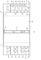
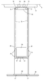
- the top view which shows the layout of the sorting system of an Example Side view of the sorting system of the embodiment
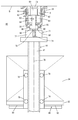
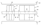
- the figure which shows the expansion of the sorting system of an Example typically Side view of the overhead transport vehicle in the embodiment
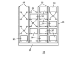
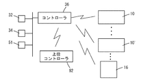
- Front view of case pallet used in examples Block diagram showing the control system of the embodiment
- FIG. 1 to 8 show a sorting system 2 according to the embodiment. 1 and 2 show the layout of the sorting system 2.
- Reference numeral 4 denotes an automatic warehouse.
- a ceiling rail 6 is provided on the ceiling 5 of the automatic warehouse.
- a traveling route including the ceiling rail 6 includes a plurality of branching and merging portions 8, and a plurality of ceiling transportation vehicles are independently branched and merged. 10 travels along the ceiling rail 6.
- the ceiling rail (hereinafter referred to as “rail”) 6 may be bidirectional, but in the embodiment, the overhead traveling vehicle 10 travels only in one direction.
- a plurality of racks 20 are provided facing the rail 6, and the ceiling transport vehicle 10 can access any frontage of any rack 20.
- a receiving area 22 is provided on the ground floor of the sorting system 2 so as to be adjacent to one end of the automatic warehouse 4, and a shipping area 24 is also provided on the ground floor so as to be adjacent to the other end of the automatic warehouse 4. Yes.
- the areas 22 and 24 are provided along the outer periphery of the travel route including the ceiling rails 6 and may be in contact with the side surface of the automatic warehouse 4.
- a station array 26 in which a plurality of stations 28 are arranged is provided.
- the overhead transport vehicle 10 can freely deliver pallets, cases, and the like at each station 28.
- a berth 30 of a truck is provided in the areas 22 and 24, and it is possible to input arrival data from the arrival terminal 32 in the arrival area 22 and to request that the received goods be transported to the rack 20.
- the shipping data is input from 34.
- Reference numeral 36 denotes a controller of the sorting system 2, which may be composed of a single computer or a plurality of computers arranged in a distributed manner.
- the evacuation lane 12 Since it is not necessary to operate all the ceiling transport vehicles 10 at all times, it is preferable to provide the evacuation lane 12 to retract the ceiling transport vehicles 10 that are not operated to reduce power consumption.
- the maintenance deck 14 is provided in the evacuation lane 12, the maintenance of the lifting platform, the carriage, etc. of the ceiling transport vehicle is facilitated.
- the retreat lane 12 is provided at a position not facing the rack 20.
- the carriage 40 runs along the ceiling rail 6, and the front and rear masts 42, 42 are suspended from the carriage 40 so as to be swingable in the running direction by pins or the like (not shown).
- the elevating platform 44 moves up and down along the masts 42 and 42, and the front and rear masts 42 and 42 are connected by the lower connecting portion 46.
- the overhead conveyance vehicle 10 can be a stacker crane in which driving units for traveling and raising / lowering are arranged on the carriage 40 on the ceiling side and the mast 42 is swingable.
- a sorting area 50 is provided over a plurality of floors along the outer periphery of the travel route composed of the ceiling rails 6.
- the ceiling transport vehicle 10 receives pallets, cases and the like. Carry in and out of the sorting area 50.
- the packages on the pallet are sorted in units of cases made up of cardboard boxes, for example, and transferred to pallets or the like for each shipping destination, or individual commodities are taken out from the pallets and sorted into cases such as buckets.
- Reference numeral 51 denotes a sorting terminal which receives and displays an instruction relating to sorting from the controller 36 and returns a sorting result to the controller 36.
- An appropriate sorting device may be installed in the sorting area 50.
- the sorter 52 takes out the cardboard boxes one by one from the pallet and transfers them to the case pallet 86 in FIG.
- Sorting system 2 can be expanded sequentially, and this situation is shown in FIG. In FIG. 3, the symbol 'indicates an element after expansion, and the numbers 2 and the like such as 2, 2' indicate the same type of element.
- the initial sorting system 2 in the upper part of FIG. 3 can be expanded to a sorting system 2 ′, which can be further expanded to a sorting system 2 ′′.
- FIGS. 4 and 5 show the structure of the ceiling transport vehicle (hereinafter referred to as “transport vehicle”) 10.
- a rail 6 is fixed to a ceiling 5 of a building to which a self-supporting rack 20 is connected.
- permanent magnets 54 are arranged along the traveling direction of the transport vehicle 10, and a non-contact power supply line 56 is installed.
- Left and right guide rails 58 and 58 are provided at the bottom of the rail 6 in order to select branching and straight travel and to control the posture at the time of joining.
- the carriage 40 of the transport vehicle 10 includes a traveling unit 59, a linear motor is constituted by the coil 60 of the traveling unit 59 and the permanent magnet 54 on the rail 6 side, receives power from the non-contact power supply line 56 by the power receiving coil 62, and wheels 64 Thus, the weight of the transport vehicle 10 is supported.
- the traveling unit 59 includes left and right guide rollers 66 and 66, and the advance / retreat control 68 advances and retracts the guide rollers 66 and 66 between a position guided by the guide rail 58 and a position not guided by the guide rail 58. In this way, the transport vehicle 10 can independently branch and join, but as described in Patent Document 1, branching and joining may be controlled by a movable portion on the rail 6 side.
- the chassis 71 of the carriage 40 is attached to the vertical shaft 70 of the traveling unit 59, and the front and rear masts 42 are swingably attached to the chassis 71 along the traveling direction by pins or the like (not shown).
- the chain 76 is driven by the motor 72 and the sprocket 74 of the chassis 71, and the lifting platform 44 and a counterweight (not shown) are moved up and down.
- the guide roller 78 of the elevator 44 is guided by the mast 42 to limit the shaking and twisting of the elevator 44, and the transfer device 81 such as a slide fork on the elevator 44 transfers the pallet 80 and the like.
- 84 is a load on the pallet 82.
- a drive medium such as a belt may be used instead of the chain, and a counterweight may not be provided.
- the lower ends of the front and rear masts 42 are connected by, for example, a horizontal connecting portion 46, a part of the load of the transport vehicle 10 is supported on the ground rail 48 via the wheels 47, and a guide roller (not shown) is guided by the ground rail 48, Limit the shaking and twisting of the mast 42.
- the mast 42 is swingable along the traveling direction, and controls the traveling unit 59 so as not to perform acceleration / deceleration in the vicinity of its natural frequency, thereby damping the mast 42.
- a damper, damping rubber or the like (not shown) is provided on the attachment portion of the mast 42 to the chassis 71 to reduce the shaking at the time of emergency stop.
- the connection part 46 and the ground rail 48 do not need to be provided, and the number, structure, etc. of the mast 42 are arbitrary.
- the sorting system 2 performs sorting from the pallet 82 to the case, in addition to the ceiling transport vehicle 10 that transports the pallet unit, a ceiling transport vehicle that transports the case unit is provided, and these travel along the same ceiling rail 6. It is preferable.
- This situation is shown in FIG. 10 ′ is a ceiling transport vehicle that transports in units of cases, the number of travel units 59 is smaller than that of the pallet ceiling transport vehicle 10, and the width of the lift platform 44 ′ along the travel direction of the rail 6 is from the lift platform 44. Is too narrow. Further, the transfer device 68 ′ is narrower than the transfer device 68 to support the article along the traveling direction of the rail 6.
- the lengths of the transfer devices 68 and 68 ′ are made equal, and the ceiling transport vehicles 10 and It is preferable that 10 'can deliver the goods together.
- the ceiling transport vehicle 10 ′ is the same as the ceiling transport vehicle 10 in other points.
- a plurality of transfer devices 68 ′ may be arranged on the lifting platform 44 ′ of the ceiling transport vehicle 10 ′ so that a plurality of cases can be transported simultaneously.
- FIG. 7 shows a case pallet 86.
- the case pallet 86 is transported by the overhead transport vehicle 10 in the same manner as the pallet 82, is placed at each frontage of the rack 20, and is transported to the sorting area 50, the shipping area 24, and the like via the station 28.
- a plurality of shelf supports 88 are fixed to a support 89 from the base 87, and a case 90 such as a cardboard box or a bucket is placed on each shelf support 88.
- the case is transferred from the pallet 82 to the case pallet 86 by the sorter 52 of FIG. 2, and placed on the rack 20, the station 28, or the like.
- the case 90 is sorted between the case pallets 86 and 86 by the ceiling transport vehicle 10 ′, the sorting is completed, and the case pallet 86 is shipped by the ceiling transport vehicle 10.
- Fig. 8 shows the control system of the sorting system 2.
- the controller 36 communicates with the terminals 32, 34, 51, receives instructions regarding sorting from the host controller 92, controls the ceiling transport vehicles 10, 10 ′, the sorter 52, etc., and executes sorting, and the execution result is sent to the host controller. Report to 92.
- the embodiment has the following characteristics. 1) An arrival area 22 and a shipping area 24 are provided on the ground floor, and a sorting area 50 is provided on the upper floor, and the overhead transport vehicle 10 is caused to travel along a travel path that can freely branch and merge. As a result, a compact sorting system 2 is obtained. 2) Since the overhead transportation vehicles 10 and 10 'can freely branch and merge and can travel to any rack 20 and any station 28, basically one kind of transportation device is sufficient. 3) The overhead transporting vehicles 10 and 10 'need only support the vertical load applied to the mast 42, and do not need rigidity along the traveling direction. Also, the ground-side cart may be simple and may not be provided. Therefore, it can be made lighter than conventional stacker cranes.
- the ceiling rail 6 can also be reduced in weight. 4) When a linear motor is used, no force in the running direction is applied to the rail 6. For this reason, the rail 6 can be further reduced in weight. 5) Power saving can be achieved by providing the evacuation lane 12, and maintenance of the ceiling transport vehicles 10, 10 'can be facilitated by providing the maintenance deck 14. 6) Sorting system 2 is rich in expandability. 7) The traveling unit 59 can be shared between the ceiling transport vehicles 10 and 10 '. 8) The pallet can be transported by the ceiling transport vehicle 10, and the case can be transported and sorted in units of cases by the ceiling transport vehicle 10 ′.
- sorting is performed on a case-by-case basis using the ceiling transport vehicle 10 ′.
- the ceiling transport vehicle is provided with both the transfer device 68 for the pallet 82 and the transfer device 68 ′ for the case 90 in the lift. It may be used.
- This ceiling transport vehicle has both functions of the ceiling transport vehicles 10 and 10 '.
- the type of the sorting device arranged in the sorting area 50, the contents of the sorting work, the method of distributing the sorting work between the worker and the device, and the like are arbitrary.
Landscapes
- Engineering & Computer Science (AREA)
- Mechanical Engineering (AREA)
- Warehouses Or Storage Devices (AREA)
Abstract
Description
分岐と合流とが自在な走行経路に沿って走行すると共に、移載装置を昇降させる搬送車と、
前記走行経路に沿って設けられ、かつ複数階分の高さを有する複数のラックと、
各々前記走行経路の外周に沿って設けられている、入荷エリアと出荷エリア及び仕分けエリアと、
入荷した商品を入荷エリアからラックを経由して仕分けエリアへ搬送し、仕分けが終わった商品を仕分けエリアから出荷エリアへ搬送するように、前記搬送車を制御するコントローラとを備えている。
仕分けシステムは、分岐と合流とが自在な走行経路に沿って走行すると共に、移載装置を昇降させる搬送車と、前記走行経路に沿って設けられ、かつ複数階分高さを有する複数のラックと、各々前記走行経路の外周に沿って設けられている、入荷エリアと出荷エリア及び仕分けエリアと、搬送車を制御するコントローラ、とを備え
前記コントローラにより前記搬送車を制御して、入荷した商品を入荷エリアからラックを経由して仕分けエリアへ搬送すると共に、仕分けが終わった商品を仕分けエリアから出荷エリアへ搬送する。
1) 地上階に入荷エリア22と出荷エリア24を、上階に仕分けエリア50を設け、分岐と合流とが自在な走行経路に沿って、天井搬送車10を走行させる。この結果、コンパクトな仕分けシステム2が得られる。
2) 天井搬送車10,10'は分岐と合流とが自在で、任意のラック20と任意のステーション28へ走行できるので、基本的に一種類の搬送装置で足りる。
3) 天井搬送車10,10'は、マスト42に加わる垂直荷重のみを支持できれば良く、走行方向に沿っての剛性を必要としない。また地上側の台車は簡素なもので良く、設けなくても良い。従って在来のスタッカークレーンに比べ軽量にできる。天井搬送車10,10'を軽量化できるので、天井レール6も軽量化できる。
4) リニアモータを用いると、レール6には走行方向の力が加わらない。このためレール6をさらに軽量化できる。
5) 退避レーン12を設けることにより省電力化でき、メンテナンスデッキ14を設けることにより天井搬送車10、10'のメンテナンスが容易になる。
6) 仕分けシステム2は拡張性に富んでいる。
7) 走行ユニット59を天井搬送車10,10'間で共通化できる。
8) 天井搬送車10によりパレットを搬送し、天井搬送車10'によりケースの搬送とケース単位での仕分けとができる。
8 分岐合流部 10 天井搬送車 12 退避レーン
14 メンテナンスデッキ 20 ラック 22 入荷エリア
24 出荷エリア 26 ステーションアレイ 28 ステーション
30 バース 32 入荷端末 34 出荷端末
36 コントローラ 40 台車 42 マスト
44 昇降台 46 連結部 48 地上レール
50 仕分けエリア 51 仕分け端末 52 ソーター
54 永久磁石 56 非接触給電線 58 ガイドレール
59 走行ユニット 60 コイル 62 受電コイル
64 車輪 66 ガイドローラ 68 進退制御
70 鉛直軸 71 シャーシ 72 モータ
74 スプロケット 76 チェーン 78 ガイドローラ
80 移載装置 82 パレット 84 荷物
86 ケースパレット 87 ベース 88 棚受
89 支柱 90 ケース 92 上位コントローラ
Claims (5)
- 入荷した商品を仕分けて出荷する仕分けシステムであって、
分岐と合流とが自在な走行経路に沿って走行すると共に、移載装置を昇降させる搬送車と、
前記走行経路に沿って設けられ、かつ複数階分の高さを有する複数のラックと、
各々前記走行経路の外周に沿って設けられている、入荷エリアと出荷エリア及び仕分けエリアと、
入荷した商品を入荷エリアからラックを経由して仕分けエリアへ搬送し、仕分けが終わった商品を仕分けエリアから出荷エリアへ搬送するように、前記搬送車を制御するコントローラとを備える仕分けシステム。 - 前記入荷エリアと前記出荷エリアとが地上階に設けられ、前記仕分けエリアが上階に設けられていることを特徴とする、請求項1の仕分けシステム。
- 前記走行経路は仕分けシステムの建屋の天井部に設けられているレールから成り、
前記搬送車は、前記レールに沿って走行する台車と、台車から吊り下げられているマストと、マストに沿って昇降し、かつ移載装置を備えている昇降台、とを有することを特徴とする、請求項1または2の仕分けシステム。 - 前記搬送車として、パレットを搬送するパレット搬送車と、ケースを搬送するケース搬送車とを備え、パレット搬送車とケース搬送車は共に前記レールに沿って走行するように構成されていることを特徴とする、請求項1~3のいずれかの仕分けシステム。
- 仕分けシステムにより入荷した商品を仕分けて出荷する仕分け方法であって、
仕分けシステムは、分岐と合流とが自在な走行経路に沿って走行すると共に、移載装置を昇降させる搬送車と、前記走行経路に沿って設けられ、かつ複数階分の高さを有する複数のラックと、各々前記走行経路の外周に沿って設けられている、入荷エリアと出荷エリア及び仕分けエリアと、搬送車を制御するコントローラ、とを備え
前記コントローラにより前記搬送車を制御して、入荷した商品を入荷エリアからラックを経由して仕分けエリアへ搬送すると共に、仕分けが終わった商品を仕分けエリアから出荷エリアへ搬送する、仕分け方法。
Priority Applications (4)
| Application Number | Priority Date | Filing Date | Title |
|---|---|---|---|
| US15/502,262 US10479601B2 (en) | 2014-08-26 | 2015-06-15 | Sorting system and sorting method |
| CN201580035877.7A CN106470919B (zh) | 2014-08-26 | 2015-06-15 | 分拣系统及分拣方法 |
| KR1020177008121A KR101999836B1 (ko) | 2014-08-26 | 2015-06-15 | 분류 시스템과 분류 방법 |
| JP2016545010A JP6315098B2 (ja) | 2014-08-26 | 2015-06-15 | 仕分けシステムと仕分け方法 |
Applications Claiming Priority (2)
| Application Number | Priority Date | Filing Date | Title |
|---|---|---|---|
| JP2014171758 | 2014-08-26 | ||
| JP2014-171758 | 2014-08-26 |
Publications (1)
| Publication Number | Publication Date |
|---|---|
| WO2016031352A1 true WO2016031352A1 (ja) | 2016-03-03 |
Family
ID=55399257
Family Applications (1)
| Application Number | Title | Priority Date | Filing Date |
|---|---|---|---|
| PCT/JP2015/067148 Ceased WO2016031352A1 (ja) | 2014-08-26 | 2015-06-15 | 仕分けシステムと仕分け方法 |
Country Status (6)
| Country | Link |
|---|---|
| US (1) | US10479601B2 (ja) |
| JP (1) | JP6315098B2 (ja) |
| KR (1) | KR101999836B1 (ja) |
| CN (1) | CN106470919B (ja) |
| TW (1) | TWI644849B (ja) |
| WO (1) | WO2016031352A1 (ja) |
Cited By (8)
| Publication number | Priority date | Publication date | Assignee | Title |
|---|---|---|---|---|
| WO2018074130A1 (ja) * | 2016-10-18 | 2018-04-26 | 村田機械株式会社 | 天井搬送車及び搬送システム |
| CN107985882A (zh) * | 2016-10-26 | 2018-05-04 | 村田机械株式会社 | 悬吊式堆垛起重机 |
| JP2018070304A (ja) * | 2016-10-26 | 2018-05-10 | 村田機械株式会社 | スタッカクレーン、及び、スタッカクレーンの組立方法 |
| JP2018070299A (ja) * | 2016-10-26 | 2018-05-10 | 村田機械株式会社 | 懸垂式スタッカクレーン |
| JP2019059568A (ja) * | 2017-09-25 | 2019-04-18 | 村田機械株式会社 | 懸垂式クレーン |
| JP2021123469A (ja) * | 2020-02-06 | 2021-08-30 | 株式会社ダイフク | 倉庫設備 |
| CN113998361A (zh) * | 2019-08-30 | 2022-02-01 | 深圳市海柔创新科技有限公司 | 分拣机器人及分拣方法 |
| US12103770B2 (en) | 2019-08-30 | 2024-10-01 | Hai Robotics Co., Ltd. | Sorting robot and sorting method |
Families Citing this family (15)
| Publication number | Priority date | Publication date | Assignee | Title |
|---|---|---|---|---|
| CN106470919B (zh) * | 2014-08-26 | 2019-08-20 | 村田机械株式会社 | 分拣系统及分拣方法 |
| WO2019021708A1 (ja) * | 2017-07-24 | 2019-01-31 | 村田機械株式会社 | 自動倉庫システム、及び自動倉庫システムの制御方法 |
| JP6780130B2 (ja) * | 2017-09-30 | 2020-11-04 | ベイジン ギークプラス テクノロジー カンパニー リミテッド | 物品仕分け搬送用のシステム、装置および方法 |
| JP6939990B2 (ja) * | 2018-05-23 | 2021-09-22 | 株式会社ダイフク | ピッキングシステム(picking system) |
| MX2020013280A (es) | 2018-06-08 | 2021-02-22 | Attabotics Inc | Sistemas mejorados de almacenamiento y recuperacion. |
| CN109205278B (zh) * | 2018-09-19 | 2020-10-27 | 湖州南浔精弘机械制造有限公司 | 一种用于物流运输线的分类式输送机 |
| US11644334B2 (en) * | 2019-02-07 | 2023-05-09 | Uber Technologies, Inc. | Route optimization system based on height parameter |
| AU2020275488B2 (en) * | 2019-05-10 | 2023-07-20 | Lafayette Systems Canada ULC | Space-efficient order fulfillment system for workflow between service areas |
| CN112053017B (zh) * | 2019-06-05 | 2024-08-02 | 顺丰科技有限公司 | 一种分拣装置分配方法、系统、终端及存储介质 |
| ES3064544T3 (en) | 2019-06-11 | 2026-04-27 | Lafayette Systems Canada ULC | Manufacturing system with an interconnected storage structure and manufacturing cells sharing a common robotic fleet |
| US11305430B2 (en) * | 2019-11-11 | 2022-04-19 | Symbotic Llc | Pallet building system with flexible sequencing |
| JP7310713B2 (ja) * | 2020-05-25 | 2023-07-19 | 株式会社ダイフク | 物品搬送設備 |
| US12219427B2 (en) | 2020-09-04 | 2025-02-04 | Uber Technologies, Inc. | Elevation-aware hotspot generation system |
| CN112793979A (zh) * | 2021-02-06 | 2021-05-14 | 武昌理工学院 | 一种仓储物流机器人集群避障及协同路径规划系统及方法 |
| JP7807891B2 (ja) * | 2021-09-29 | 2026-01-28 | 株式会社Subaru | 貨物受取設備 |
Citations (7)
| Publication number | Priority date | Publication date | Assignee | Title |
|---|---|---|---|---|
| JPS5435390B1 (ja) * | 1974-03-20 | 1979-11-02 | ||
| US4678390A (en) * | 1986-03-26 | 1987-07-07 | Societe Anonyme Redoute Catalogue | Automated self-powered material handling truck |
| JPS6337006A (ja) * | 1986-07-31 | 1988-02-17 | Daifuku Co Ltd | 物品仕分け設備 |
| JPH04327404A (ja) * | 1991-04-25 | 1992-11-17 | Daifuku Co Ltd | 荷取扱い設備 |
| JPH10218307A (ja) * | 1997-02-03 | 1998-08-18 | Daifuku Co Ltd | 物品搬送装置 |
| JP2001026310A (ja) * | 1999-07-16 | 2001-01-30 | Ishida Co Ltd | ソーティングシステム |
| JP2002338015A (ja) * | 2001-05-15 | 2002-11-27 | Ishida Co Ltd | 商品仕分けシステム |
Family Cites Families (35)
| Publication number | Priority date | Publication date | Assignee | Title |
|---|---|---|---|---|
| US3033392A (en) * | 1960-03-21 | 1962-05-08 | Western Electric Co | Stock storage and selection system |
| US3531705A (en) * | 1965-11-05 | 1970-09-29 | Eaton Yale & Towne | Method and apparatus for automatic load transfer |
| US3863777A (en) * | 1972-07-19 | 1975-02-04 | Tsubakimoto Chain Co | Article storage and handling system |
| US3776399A (en) * | 1972-09-29 | 1973-12-04 | Triax Co | Automatic warehousing system |
| US3792785A (en) | 1973-01-26 | 1974-02-19 | Fmc Corp | Automated storage and freight terminal apparatus |
| JPS5337622B2 (ja) * | 1973-12-05 | 1978-10-11 | ||
| JPS6025326B2 (ja) * | 1976-09-11 | 1985-06-18 | 株式会社ダイフク | 格納設備 |
| JPS63242809A (ja) | 1987-03-27 | 1988-10-07 | Murata Mach Ltd | 物品収納庫 |
| EP0627371B1 (de) * | 1993-06-04 | 1997-12-10 | Ferag AG | Sortimentierverfahren und Vorrichtung dazu |
| US20070276535A1 (en) * | 1999-07-30 | 2007-11-29 | Gerhard Haag | Automated warehouse facility |
| JP3832293B2 (ja) * | 2001-08-31 | 2006-10-11 | 株式会社ダイフク | 荷保管設備 |
| WO2004001582A1 (en) * | 2002-06-19 | 2003-12-31 | Brooks Automation, Inc. | Automated material handling system for semiconductor manufacturing based on a combination of vertical carousels and overhead hoists |
| CN1845799A (zh) * | 2003-09-03 | 2006-10-11 | 西门子公司 | 用于处理例外邮件的方法及系统 |
| JP4045451B2 (ja) * | 2003-12-26 | 2008-02-13 | 村田機械株式会社 | 天井走行車システム |
| JP4123383B2 (ja) * | 2004-08-12 | 2008-07-23 | 村田機械株式会社 | 天井走行車システム |
| JP4221603B2 (ja) * | 2005-03-31 | 2009-02-12 | 村田機械株式会社 | 天井走行車システム |
| JP4441931B2 (ja) * | 2005-05-06 | 2010-03-31 | 村田機械株式会社 | 搬送台車システム |
| CN200948958Y (zh) * | 2006-08-17 | 2007-09-19 | 贵阳普天万向物流技术股份有限公司 | 一种通道式件烟自动分类仓储装置 |
| JP4688824B2 (ja) * | 2007-01-12 | 2011-05-25 | 村田機械株式会社 | 天井走行車システム及び天井走行車システムの周囲の処理装置の搬出入方法 |
| JP2008172062A (ja) * | 2007-01-12 | 2008-07-24 | Murata Mach Ltd | 物品供給装置 |
| DE102007005561B4 (de) * | 2007-01-24 | 2009-11-26 | SSI Schäfer Noell GmbH Lager- und Systemtechnik | Kommissioniersystem mit Regaltransporteinheit und Verfahren zum Betreiben eines solchen Systems |
| JP2009280294A (ja) | 2008-05-19 | 2009-12-03 | Yamato Logistics Co Ltd | 物品搬送システム |
| JP5382470B2 (ja) * | 2010-11-04 | 2014-01-08 | 村田機械株式会社 | 搬送システム及び搬送方法 |
| DE102011050437A1 (de) | 2011-05-17 | 2012-11-22 | Swisslog Ag | Verfahren zum Lagern und/oder Kommissionieren von Wareneinheiten |
| US8827090B2 (en) * | 2011-07-18 | 2014-09-09 | Holland Storage Systems Llc | Three-dimensional storage system |
| JP5674041B2 (ja) * | 2011-08-11 | 2015-02-18 | 株式会社ダイフク | 物品搬送設備 |
| JP5590420B2 (ja) | 2011-12-21 | 2014-09-17 | 株式会社ダイフク | 物品搬送設備 |
| JP5880991B2 (ja) * | 2012-06-08 | 2016-03-09 | 村田機械株式会社 | 搬送システム及び搬送システムでの物品の一時保管方法 |
| CN102968709B (zh) * | 2012-11-30 | 2016-04-27 | 上海意利信息科技有限公司 | 生产线自动分拣配送系统及方法 |
| WO2015071951A1 (ja) * | 2013-11-12 | 2015-05-21 | 株式会社ダイフク | 物品収納設備(article storage facility) |
| CN106470919B (zh) * | 2014-08-26 | 2019-08-20 | 村田机械株式会社 | 分拣系统及分拣方法 |
| KR101676795B1 (ko) * | 2015-03-16 | 2016-11-16 | 크린팩토메이션 주식회사 | 웨이퍼 캐리어 반송 로봇 |
| US9617075B2 (en) * | 2015-03-24 | 2017-04-11 | Joseph Porat | System and method for overhead warehousing |
| US9758301B2 (en) * | 2015-03-24 | 2017-09-12 | Joseph Porat | System and method for overhead warehousing |
| JP6531642B2 (ja) * | 2015-12-24 | 2019-06-19 | 株式会社ダイフク | 物品搬送設備 |
-
2015
- 2015-06-15 CN CN201580035877.7A patent/CN106470919B/zh not_active Expired - Fee Related
- 2015-06-15 US US15/502,262 patent/US10479601B2/en not_active Expired - Fee Related
- 2015-06-15 KR KR1020177008121A patent/KR101999836B1/ko not_active Expired - Fee Related
- 2015-06-15 WO PCT/JP2015/067148 patent/WO2016031352A1/ja not_active Ceased
- 2015-06-15 JP JP2016545010A patent/JP6315098B2/ja active Active
- 2015-08-13 TW TW104126380A patent/TWI644849B/zh not_active IP Right Cessation
Patent Citations (7)
| Publication number | Priority date | Publication date | Assignee | Title |
|---|---|---|---|---|
| JPS5435390B1 (ja) * | 1974-03-20 | 1979-11-02 | ||
| US4678390A (en) * | 1986-03-26 | 1987-07-07 | Societe Anonyme Redoute Catalogue | Automated self-powered material handling truck |
| JPS6337006A (ja) * | 1986-07-31 | 1988-02-17 | Daifuku Co Ltd | 物品仕分け設備 |
| JPH04327404A (ja) * | 1991-04-25 | 1992-11-17 | Daifuku Co Ltd | 荷取扱い設備 |
| JPH10218307A (ja) * | 1997-02-03 | 1998-08-18 | Daifuku Co Ltd | 物品搬送装置 |
| JP2001026310A (ja) * | 1999-07-16 | 2001-01-30 | Ishida Co Ltd | ソーティングシステム |
| JP2002338015A (ja) * | 2001-05-15 | 2002-11-27 | Ishida Co Ltd | 商品仕分けシステム |
Cited By (13)
| Publication number | Priority date | Publication date | Assignee | Title |
|---|---|---|---|---|
| WO2018074130A1 (ja) * | 2016-10-18 | 2018-04-26 | 村田機械株式会社 | 天井搬送車及び搬送システム |
| US10988359B2 (en) | 2016-10-18 | 2021-04-27 | Murata Machinery, Ltd. | Overhead transport vehicle and transport system |
| JPWO2018074130A1 (ja) * | 2016-10-18 | 2019-07-25 | 村田機械株式会社 | 天井搬送車及び搬送システム |
| JP2018070299A (ja) * | 2016-10-26 | 2018-05-10 | 村田機械株式会社 | 懸垂式スタッカクレーン |
| JP2018070295A (ja) * | 2016-10-26 | 2018-05-10 | 村田機械株式会社 | 懸垂式スタッカクレーン |
| JP2018070304A (ja) * | 2016-10-26 | 2018-05-10 | 村田機械株式会社 | スタッカクレーン、及び、スタッカクレーンの組立方法 |
| CN107985882A (zh) * | 2016-10-26 | 2018-05-04 | 村田机械株式会社 | 悬吊式堆垛起重机 |
| JP2019059568A (ja) * | 2017-09-25 | 2019-04-18 | 村田機械株式会社 | 懸垂式クレーン |
| CN113998361A (zh) * | 2019-08-30 | 2022-02-01 | 深圳市海柔创新科技有限公司 | 分拣机器人及分拣方法 |
| CN113998361B (zh) * | 2019-08-30 | 2022-12-13 | 深圳市海柔创新科技有限公司 | 分拣机器人及分拣方法 |
| US12103770B2 (en) | 2019-08-30 | 2024-10-01 | Hai Robotics Co., Ltd. | Sorting robot and sorting method |
| JP2021123469A (ja) * | 2020-02-06 | 2021-08-30 | 株式会社ダイフク | 倉庫設備 |
| JP7226361B2 (ja) | 2020-02-06 | 2023-02-21 | 株式会社ダイフク | 倉庫設備 |
Also Published As
| Publication number | Publication date |
|---|---|
| US20170217681A1 (en) | 2017-08-03 |
| CN106470919B (zh) | 2019-08-20 |
| TW201612093A (en) | 2016-04-01 |
| US10479601B2 (en) | 2019-11-19 |
| KR101999836B1 (ko) | 2019-07-12 |
| JPWO2016031352A1 (ja) | 2017-06-01 |
| JP6315098B2 (ja) | 2018-04-25 |
| CN106470919A (zh) | 2017-03-01 |
| TWI644849B (zh) | 2018-12-21 |
| KR20170044726A (ko) | 2017-04-25 |
Similar Documents
| Publication | Publication Date | Title |
|---|---|---|
| JP6315098B2 (ja) | 仕分けシステムと仕分け方法 | |
| JP6315097B2 (ja) | ピッキングシステムとピッキング方法 | |
| JP6521063B2 (ja) | 自動倉庫及び懸垂式スタッカクレーン | |
| KR101676717B1 (ko) | 자동창고 시스템 | |
| CN104302562B (zh) | 搬运系统以及搬运系统中的物品的临时保管方法 | |
| JP6291228B2 (ja) | 自動保管設備及び自動倉庫 | |
| JP2018115071A (ja) | 自走式搬送台車を用いた保管設備 | |
| KR20180045810A (ko) | 현수식 스태커 크레인 | |
| JP2017030944A (ja) | 搬送システム | |
| JP5783366B2 (ja) | 仕分けシステム | |
| JP6531626B2 (ja) | 自動倉庫システム | |
| JP6424705B2 (ja) | 搬送車システム | |
| JP6798250B2 (ja) | 走行車 | |
| JP6801364B2 (ja) | 懸垂式スタッカクレーン | |
| CN114056818A (zh) | 穿梭车货物一体化提升机、存取系统及一体化系统 | |
| WO2012101718A1 (ja) | 自動倉庫システム、搬出方法 | |
| JP2018070307A (ja) | 自動倉庫 |
Legal Events
| Date | Code | Title | Description |
|---|---|---|---|
| 121 | Ep: the epo has been informed by wipo that ep was designated in this application |
Ref document number: 15835979 Country of ref document: EP Kind code of ref document: A1 |
|
| WWE | Wipo information: entry into national phase |
Ref document number: 15502262 Country of ref document: US |
|
| ENP | Entry into the national phase |
Ref document number: 2016545010 Country of ref document: JP Kind code of ref document: A |
|
| NENP | Non-entry into the national phase |
Ref country code: DE |
|
| ENP | Entry into the national phase |
Ref document number: 20177008121 Country of ref document: KR Kind code of ref document: A |
|
| 122 | Ep: pct application non-entry in european phase |
Ref document number: 15835979 Country of ref document: EP Kind code of ref document: A1 |