WO2014054553A1 - シートのバックレスト - Google Patents
シートのバックレスト Download PDFInfo
- Publication number
- WO2014054553A1 WO2014054553A1 PCT/JP2013/076474 JP2013076474W WO2014054553A1 WO 2014054553 A1 WO2014054553 A1 WO 2014054553A1 JP 2013076474 W JP2013076474 W JP 2013076474W WO 2014054553 A1 WO2014054553 A1 WO 2014054553A1
- Authority
- WO
- WIPO (PCT)
- Prior art keywords
- backrest
- pressure receiving
- receiving member
- wire
- frame
- Prior art date
- Legal status (The legal status is an assumption and is not a legal conclusion. Google has not performed a legal analysis and makes no representation as to the accuracy of the status listed.)
- Ceased
Links
Images






















Classifications
-
- B—PERFORMING OPERATIONS; TRANSPORTING
- B60—VEHICLES IN GENERAL
- B60N—SEATS SPECIALLY ADAPTED FOR VEHICLES; VEHICLE PASSENGER ACCOMMODATION NOT OTHERWISE PROVIDED FOR
- B60N2/00—Seats specially adapted for vehicles; Arrangement or mounting of seats in vehicles
- B60N2/24—Seats specially adapted for vehicles; Arrangement or mounting of seats in vehicles for particular purposes or particular vehicles
- B60N2/42—Seats specially adapted for vehicles; Arrangement or mounting of seats in vehicles for particular purposes or particular vehicles the seat constructed to protect the occupant from the effect of abnormal g-forces, e.g. crash or safety seats
-
- B—PERFORMING OPERATIONS; TRANSPORTING
- B60—VEHICLES IN GENERAL
- B60N—SEATS SPECIALLY ADAPTED FOR VEHICLES; VEHICLE PASSENGER ACCOMMODATION NOT OTHERWISE PROVIDED FOR
- B60N2/00—Seats specially adapted for vehicles; Arrangement or mounting of seats in vehicles
- B60N2/24—Seats specially adapted for vehicles; Arrangement or mounting of seats in vehicles for particular purposes or particular vehicles
- B60N2/42—Seats specially adapted for vehicles; Arrangement or mounting of seats in vehicles for particular purposes or particular vehicles the seat constructed to protect the occupant from the effect of abnormal g-forces, e.g. crash or safety seats
- B60N2/4207—Seats specially adapted for vehicles; Arrangement or mounting of seats in vehicles for particular purposes or particular vehicles the seat constructed to protect the occupant from the effect of abnormal g-forces, e.g. crash or safety seats characterised by the direction of the g-forces
- B60N2/4214—Seats specially adapted for vehicles; Arrangement or mounting of seats in vehicles for particular purposes or particular vehicles the seat constructed to protect the occupant from the effect of abnormal g-forces, e.g. crash or safety seats characterised by the direction of the g-forces longitudinal
- B60N2/4228—Seats specially adapted for vehicles; Arrangement or mounting of seats in vehicles for particular purposes or particular vehicles the seat constructed to protect the occupant from the effect of abnormal g-forces, e.g. crash or safety seats characterised by the direction of the g-forces longitudinal due to impact coming from the rear
-
- B—PERFORMING OPERATIONS; TRANSPORTING
- B60—VEHICLES IN GENERAL
- B60N—SEATS SPECIALLY ADAPTED FOR VEHICLES; VEHICLE PASSENGER ACCOMMODATION NOT OTHERWISE PROVIDED FOR
- B60N2/00—Seats specially adapted for vehicles; Arrangement or mounting of seats in vehicles
- B60N2/24—Seats specially adapted for vehicles; Arrangement or mounting of seats in vehicles for particular purposes or particular vehicles
- B60N2/42—Seats specially adapted for vehicles; Arrangement or mounting of seats in vehicles for particular purposes or particular vehicles the seat constructed to protect the occupant from the effect of abnormal g-forces, e.g. crash or safety seats
- B60N2/427—Seats or parts thereof displaced during a crash
- B60N2/42727—Seats or parts thereof displaced during a crash involving substantially rigid displacement
- B60N2/42745—Seats or parts thereof displaced during a crash involving substantially rigid displacement of the back-rest
-
- B—PERFORMING OPERATIONS; TRANSPORTING
- B60—VEHICLES IN GENERAL
- B60N—SEATS SPECIALLY ADAPTED FOR VEHICLES; VEHICLE PASSENGER ACCOMMODATION NOT OTHERWISE PROVIDED FOR
- B60N2/00—Seats specially adapted for vehicles; Arrangement or mounting of seats in vehicles
- B60N2/64—Back-rests or cushions
-
- B—PERFORMING OPERATIONS; TRANSPORTING
- B60—VEHICLES IN GENERAL
- B60N—SEATS SPECIALLY ADAPTED FOR VEHICLES; VEHICLE PASSENGER ACCOMMODATION NOT OTHERWISE PROVIDED FOR
- B60N2/00—Seats specially adapted for vehicles; Arrangement or mounting of seats in vehicles
- B60N2/64—Back-rests or cushions
- B60N2/66—Lumbar supports
-
- B—PERFORMING OPERATIONS; TRANSPORTING
- B60—VEHICLES IN GENERAL
- B60N—SEATS SPECIALLY ADAPTED FOR VEHICLES; VEHICLE PASSENGER ACCOMMODATION NOT OTHERWISE PROVIDED FOR
- B60N2/00—Seats specially adapted for vehicles; Arrangement or mounting of seats in vehicles
- B60N2/64—Back-rests or cushions
- B60N2/66—Lumbar supports
- B60N2/665—Lumbar supports using inflatable bladders
-
- B—PERFORMING OPERATIONS; TRANSPORTING
- B60—VEHICLES IN GENERAL
- B60N—SEATS SPECIALLY ADAPTED FOR VEHICLES; VEHICLE PASSENGER ACCOMMODATION NOT OTHERWISE PROVIDED FOR
- B60N2/00—Seats specially adapted for vehicles; Arrangement or mounting of seats in vehicles
- B60N2/64—Back-rests or cushions
- B60N2/66—Lumbar supports
- B60N2/666—Lumbar supports vertically adjustable
-
- B—PERFORMING OPERATIONS; TRANSPORTING
- B60—VEHICLES IN GENERAL
- B60N—SEATS SPECIALLY ADAPTED FOR VEHICLES; VEHICLE PASSENGER ACCOMMODATION NOT OTHERWISE PROVIDED FOR
- B60N2/00—Seats specially adapted for vehicles; Arrangement or mounting of seats in vehicles
- B60N2/64—Back-rests or cushions
- B60N2/66—Lumbar supports
- B60N2/667—Lumbar supports having flexible support member bowed by applied forces
- B60N2/6671—Lumbar supports having flexible support member bowed by applied forces with cable actuators
-
- B—PERFORMING OPERATIONS; TRANSPORTING
- B60—VEHICLES IN GENERAL
- B60N—SEATS SPECIALLY ADAPTED FOR VEHICLES; VEHICLE PASSENGER ACCOMMODATION NOT OTHERWISE PROVIDED FOR
- B60N2/00—Seats specially adapted for vehicles; Arrangement or mounting of seats in vehicles
- B60N2/68—Seat frames
-
- B—PERFORMING OPERATIONS; TRANSPORTING
- B60—VEHICLES IN GENERAL
- B60N—SEATS SPECIALLY ADAPTED FOR VEHICLES; VEHICLE PASSENGER ACCOMMODATION NOT OTHERWISE PROVIDED FOR
- B60N2/00—Seats specially adapted for vehicles; Arrangement or mounting of seats in vehicles
- B60N2/68—Seat frames
- B60N2/686—Panel like structures
-
- B—PERFORMING OPERATIONS; TRANSPORTING
- B60—VEHICLES IN GENERAL
- B60N—SEATS SPECIALLY ADAPTED FOR VEHICLES; VEHICLE PASSENGER ACCOMMODATION NOT OTHERWISE PROVIDED FOR
- B60N2/00—Seats specially adapted for vehicles; Arrangement or mounting of seats in vehicles
- B60N2/70—Upholstery springs ; Upholstery
- B60N2/7094—Upholstery springs
-
- B—PERFORMING OPERATIONS; TRANSPORTING
- B60—VEHICLES IN GENERAL
- B60N—SEATS SPECIALLY ADAPTED FOR VEHICLES; VEHICLE PASSENGER ACCOMMODATION NOT OTHERWISE PROVIDED FOR
- B60N2/00—Seats specially adapted for vehicles; Arrangement or mounting of seats in vehicles
- B60N2/70—Upholstery springs ; Upholstery
- B60N2/72—Attachment or adjustment thereof
Definitions
- the present invention relates to a seat backrest.
- a headrest is provided at the upper end of the backrest of the vehicle seat.
- the headrest supports the occupant's head from behind.
- the head of the occupant is received by the headrest, thereby mitigating the impact on the occupant's neck.
- Patent Document 1 A technique has been developed (see Patent Document 1). Specifically, a pressure receiving member is provided inside the frame of the frame-shaped backrest so as to be able to swing back and forth, and at least the front side of the frame and the pressure receiving member is covered with a cushion pad (see Patent Document 1). According to the technique described in Patent Document 1, when the other vehicle collides with the rear part of the host vehicle from behind the host vehicle, the upper body of the occupant sinks into the cushion pad, and the central part of the cushion pad and the pressure receiving member move backward. Therefore, the head of the occupant is quickly received by the headrest.
- the upper connecting wire is installed between the upper parts of the left and right side frames of the backrest, and the lower connecting wire is installed between the lower parts of the left and right side frames.
- the pressure receiving members are arranged between the left and right side frames, and the pressure receiving members support the backrest pads from the rear.
- Patent Document 3 a plurality of springs are fixed to the frame of the backrest so as to traverse left and right, a support material is attached to the front side of the spring, and an airbag is attached to the front side of the support material. Then, the shape of the pad on the front side of the airbag is deformed by inflating or contracting the airbag. Thereby, the support position of a passenger
- a baffle attachment member (blanket fitting) is attached to the side frame of the backrest frame described in Patent Document 1, and the baffle attachment member is disposed around the pressure receiving member.
- a webbing is applied to the webbing attachment member, and the deployment direction of the airbag is regulated by the webbing.
- the attachment member and the airbag module are attached to the side frame of the backrest, and the blanket is stretched from the attachment member to the seam of the skin through the periphery of the airbag module.
- the air bag of the air bag module is inflated, the air bag is guided to the seam by the power cloth, and when the power cloth is pulled by the inflating air bag, the seam seam is torn and the seam is torn.
- the airbag protrudes from the spot (see Patent Document 4).
- a vibration generating unit that generates vibration is provided inside the backrest. If the seat back is vibrated by the vibration generating unit, it is possible to give the occupant a massage effect, an awakening effect, and the like.
- Japanese Unexamined Patent Publication No. 2012-136056 Japanese Unexamined Patent Publication No. 2010-179754 Japanese Laid-Open Patent Publication No. 2001-150988 Japanese Patent No. 4454860 Japanese National Utility Model Publication No. 61-19684
- bank portions are provided on the left and right sides of the front surface of the cushion pad of the backrest, and these bank portions bulge forward from the central back support portion.
- the bank is intended to improve the occupant's holdability, and the left and right sides of the occupant's upper body (mainly shoulders, shoulder blades, flank, upper arm, etc.) are received by the bank.
- the left and right sides of the occupant's upper body are received by the bank unit, and the bank unit is delayed after the central back support unit and the pressure receiving member are moved backward. Is pushed backward by the left and right sides of the occupant's upper body to compress. For this reason, the bank portion may reduce the effect of sinking the upper body of the occupant backward.
- the problem to be solved by the present invention is to prevent the bank portion from reducing the effect of sinking the occupant's upper body backward.
- a seat backrest for solving the above-described problems includes a left and right side frame arranged side by side to the left and right, a pressure receiving member provided between the side frames and provided to be swingable back and forth.
- a cushion pad covering the front surface of the side frame and the front surface of the pressure receiving member, and the pressure receiving member extends leftward and rightward from the main body portion and the left and right side portions of the main body portion, respectively.
- a back support portion that covers the front surface of the main body portion, and left and right both sides of the front surface of the back support portion provided on the left and right sides of the back support portion.
- a bank portion that covers the front surface of the extension portion and the front surface of the side frame, and faces the extension portion of the surface on the back side of the bank portion.
- a recess is formed in the part To have.
- the concave portion is formed on the back surface of the bank portion, a space in which the portion of the bank portion where the concave portion is formed is retracted and bent is secured.
- the portion of the bank where the recess is formed is retracted and bent. . Therefore, it can suppress that the occupant's upper body sinks back by the bank part.
- the portion of the bank where the recess is formed is received by the extending portion of the pressure receiving member.
- FIG. 7 is a cross-sectional view showing a cross section taken along the line VII-VII shown in FIG.
- FIG. 7 is an explanatory diagram showing the behavior of each part of the backrest in the cross section along VII-VII shown in FIG. 6. It is a perspective view of the sheet
- FIG. 1 It is a cross-sectional view of the backrest which concerns on the modification 3 of the embodiment. It is a perspective view of the sheet
- FIG. 31 is a cross-sectional view of XXXI-XXXI shown in FIG. 30. It is a perspective view of the frame of the backrest which concerns on the modification 1 of the embodiment. It is a front view of the backrest which concerns on the modification 1 of the embodiment, and the flame
- FIG. 34 is a cross-sectional view of XXXIV-XXXIV shown in FIG. 33. It is a perspective view of the sheet
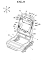
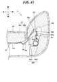
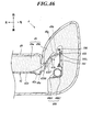
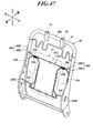
- FIG. 43 is a cross-sectional view of XXXXIII-XXXXIII shown in FIG. 42. It is an expanded sectional view of the backrest concerning modification 1 of the embodiment. It is an expanded sectional view of the backrest for demonstrating the location changed from the backrest shown in FIG. It is an expanded sectional view of the backrest concerning modification 2 of the embodiment. It is a perspective view of the frame of the backrest which concerns on the modification 3 of the embodiment. It is a front view of the frame of the backrest which concerns on the modification 3 of the embodiment. It is an expanded sectional view of the backrest concerning modification 3 of the embodiment. It is the perspective view which showed the front side of the flame
- FIG. 1 is a side view of the seat 1
- FIG. 2 is a perspective view of the frame of the seat 1.
- This seat 1 is a vehicle seat, particularly a vehicle seat provided in the interior of an automobile.
- the seat 1 is used as a driver seat or a passenger seat.
- the seat 1 includes a slide rail 2, a bottom seat (seat cushion) 3, a backrest (seat back) 4, a reclining mechanism 5, a headrest 6, and the like.
- the headrest 6 is provided at the upper end of the backrest 4, the lower end of the backrest 4 is connected to the rear end of the bottom seat 3 by the reclining mechanism 5, and the backrest 4 is raised at the rear end of the bottom seat 3. Yes.
- the backrest 4 falls back with respect to the bottom seat 3 by the reclining mechanism 5 with the lower end portion as a fulcrum and rises forward.
- the reclining mechanism 5 locks the backrest 4 to the bottom seat 3 to stop the tilting of the backrest 4 and releases the lock to urge the backrest 4 in a direction in which the backrest 4 rises forward.
- the seat 1 When the occupant sits on the seat 1, the occupant's buttocks and thighs are supported by the bottom seat 3 from below, the occupant's upper body is supported from behind by the backrest 4, and the occupant's head is supported by the headrest 6 from behind. Supported.
- the rear part of the host vehicle referring to the vehicle provided with the seat 1
- the load to back acts on the backrest 4 from a passenger
- the seat 1 is configured to sink the upper body of the occupant into the backrest 4.
- the bottom seat 3 has a frame (bottom seat frame) 30, a cushion pad 38 and a skin 39.
- a frame 30 is built in the bottom sheet 3, and this frame 30 constitutes a frame of the bottom sheet 3.
- the frame 30 is shaped like a frame, the frame 30 is wrapped in the cushion pad 38, and the epidermis 39 covers the cushion pad 38.
- the skin 39 is made of synthetic leather or fabric, for example.
- a frame 30 is attached to the slide rail 2, and the bottom seat 3 is provided so as to be movable back and forth by the slide rail 2.
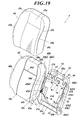
- the backrest 4 includes a frame (backrest frame) 40, a pressure receiving member 41, a cross member 42, an upper wire (wire material) 43, a lower wire (wire material) 44, a cushion pad (backrest pad) 48, an outer skin 49, and the like.
- a frame (backrest frame) 40 is built in the backrest 4, and this frame 40 constitutes a frame of the backrest 4.
- the frame 40 is formed in a frame shape, a pressure receiving member 41 is provided in the frame 40, the frame 40 and the pressure receiving member 41 are wrapped in the cushion pad 48, and the skin 49 is formed on the cushion pad 48. It is covered.
- the skin 49 is made of synthetic leather or fabric, for example.
- the lower end portion of the frame 40 is connected to the reclining mechanism 5, the reclining mechanism 5 is connected to the rear end portion of the frame 30, and the frame 40 is provided to be tiltable back and forth by the reclining mechanism 5.
- the assembly of the frame 30 of the bottom seat 3, the frame 40 of the backrest 4, and the reclining mechanism 5 is referred to as a seat frame.
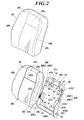
- FIG. 2 is an exploded perspective view of the backrest 4
- FIG. 3 is a front view of the frame 40 of the backrest 4.
- the frame 40 includes an upper frame (horizontal pipe portion) 40a, side frames 40b and 40b, and a lower frame 40c.
- the side frames 40b and 40b are arranged side by side with a space therebetween and extend vertically.
- the upper frame 40a extends left and right, the left end of the upper frame 40a is connected to the upper end of the left side frame 40b, and the right end of the upper frame 40a is connected to the upper end of the right side frame 40b.
- a support bracket 91 for attaching the headrest 6 is fixed to the upper frame 40a by welding.
- the lower frame 40c extends left and right, the left end of the lower frame 40c is connected to the lower end of the left side frame 40b, and the right end of the lower frame 40c is connected to the lower end of the right side frame 40b.
- the side frame 40b includes a vertical pipe portion 40b1 and a side frame main body portion 40b2.
- the left and right vertical pipe portions 40b1 and 40b1 are bent downward from the left and right ends of the upper frame 40a, and the vertical pipe portions 40b1 and 40b1 and the upper frame 40a are integrally formed. That is, the vertical pipe portions 40b1 and 40b1 and the upper frame 40a are configured by bending the pipe material into a gate shape (for example, an inverted U shape, a horizontal C shape, or a horizontal U shape).
- the side frame main body portions 40b2 and 40b2 are made of a pressed metal plate.
- the cross-sectional shape along the left-right front-rear direction of the side frame main body portions 40b2, 40b2 is substantially U-shaped.
- the side frame main body portions 40b2 and 40b2 are opposed to each other at an interval in the left-right direction, and the left and right side frame main body portions 40b2 and 40b2 are welded to the lower portions of the left and right vertical pipe portions 40b1 and 40b1, respectively.
- 40b2 extends downward from the lower ends of the vertical pipe portions 40b1 and 40b1.
- the lower frame 40c is made of a metal plate, and the left and right ends of the lower frame 40c are welded to the lower ends of the side frame main body portions 40b2 and 40b2, respectively. Further, a projecting portion 40b3 projecting forward is formed at the lower part of the side frame main body portions 40b2 and 40b2.
- a cross member 42 is provided between the side frames 40b and 40b.
- the cross member 42 is composed of a rod member that is formed into a waveform when viewed from the front.
- the left and right ends of the cross member 42 are connected to the vertical pipe portions 40b1 and 40b1, respectively, by welding or the like.
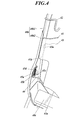
- FIG. 4 is a perspective view showing the side frame 40b and the like.
- the pressure receiving member 41 is connected to the frame 40 via an upper wire 43 and a lower wire 44 that are stretched over the frame 40, and is provided so as to be able to retreat relative to the side frame main body portion 40b2. That is, the pressure receiving member 41 is provided so as to partially close the opening of the frame surrounded by the frame 40, and is provided to be swingable back and forth by the upper wire (wire material) 43 and the lower wire 44 (wire material). .
- the upper wire (spring wire) 43 and the lower wire (spring wire) 44 are members for connecting the pressure receiving member 41 to the frame 40.
- the upper wire 43 is installed between the side frames 40b and 40b below the cross member 42, and the left and right ends of the upper wire 43 are connected to the vertical pipe portions 40b1 and 40b1, respectively.
- the attachment portions (support tongues) 43a and 43a are attached to the vertical pipe portions 40b1 and 40b1 by welding or the like, and the left and right ends of the upper wire 43 are hooked on the attachment portions 43a and 43a.
- the positions where the attachment portions 43a and 43a are attached to the vertical pipe portions 40b1 and 40b1 avoid the front ends of the vertical pipe portions 40b1 and 40b1, and are inside the frame 40 from the front ends of the vertical pipe portions 40b1 and 40b1.
- the upper wire 43 is formed in a waveform when viewed from the front.
- the upper wire 43 has flexibility and elasticity, and the cross member 42 has sufficiently higher rigidity than the upper wire 43.
- the lower wire 44 is installed between the side frame main body portions 40b2 and 40b2 below the upper wire 43. Specifically, the right end of the lower wire 44 is connected to the right swing member (link member) 45a, and the left end of the lower wire 44 is similarly connected to the left swing member 45a. 45a can swing back and forth and is connected to the left and right side frame main body portions 40b2 and 40b2. Stoppers 45b and 45c are arranged before and after the swing member 45a, and these stoppers 45b and 45c are fixed to the side frame main body 40b2. One end of a tension spring 45d is connected to the swing member 45a, and the tension spring 45d is connected to the side frame 40b on the front side of the swing member 45a.
- the tension spring 45d pulls the swing member 45a forward, and the swing member 45a contacts the front stopper 45b, whereby the tensile load of the tension spring 45d is received by the stopper 45b.
- a backward load greater than a predetermined value acts on the lower wire 44 and the pressure receiving member 41, the swing member 45a swings backward against the tensile load of the tension spring 45d, and the swing member 45a The rocking member 45a is stopped by coming into contact with the stopper 45c.
- the lower wire 44 is formed in a waveform when viewed from the front.
- the lower wire 44 has flexibility and elasticity, and the cross member 42 has sufficiently higher rigidity than the lower wire 44.
- the pressure receiving member 41 is supported by the upper wire 43 and the lower wire 44, and the pressure receiving member 41 is disposed between the side frames 40b and 40b in a state of being suspended by the upper wire 43 and the lower wire 44. Further, the pressure receiving member 41 is disposed below the cross member 42.
- the pressure receiving member 41 is a plate-shaped resin plate. More specifically, the pressure receiving member 41 is made of a synthetic resin such as polypropylene and has a predetermined strength capable of supporting a seated person. A plurality of claws (engaging claws) 41c, 41c ... and claws 41d, 41d ... are formed on the rear surface of the pressure receiving member 41, the upper wire 43 is hooked on the claws 41c, 41c ..., and the lower wire 44 is hooked on the claws 41d, 41d ... By being hooked, the pressure receiving member 41 is supported by the upper wire 43 and the lower wire 44 in a standing state.
- the upper wire 43 is engaged with the claw 41c formed on the upper rear surface of the pressure receiving member 41, thereby connecting the upper portion of the pressure receiving member 41 to the left and right side frames 40b.
- the lower wire 44 is engaged with a claw 41d formed on the lower rear surface of the pressure receiving member 41, thereby connecting the pressure receiving member 41 to the left and right side frames 40b.
- the claws 41c and 41d are substantially L-shaped when viewed from the left or right. That is, the claws 41c and 41d extend rearward from the rear surface of the main body 41a, bend downward at the tip, and extend downward from the bent portion.
- the pressure receiving member 41 has a main body portion (pressure receiving portion) 41a and a pair of left and right extending portions (supporting portions) 41b and 41b.
- the main body 41a is provided in a plate shape that extends vertically and horizontally.
- the left extending portion 41b extends leftward from the upper portion of the left side portion of the main body portion 41a, and the right extending portion 41b extends rightward from the upper portion of the right side portion of the main body portion 41a.
- the extending portions 41b and 41b extend from the portion corresponding to the height of the chest of the occupant of the main body portion 41a toward the diagonally forward side on the outer side in the left-right direction.
- the extension portions 41b and 41b are curved forward from both the left and right sides of the main body portion 41a, and when the extension portions 41b and 41b and the main body portion 41a are viewed from above, the extension portions 41b and 41b and the main body portion 41a are rearward as a whole. Curved into a convex and concave cylindrical shape.
- the extension portion 41b and the main body portion 41a are integrally formed.
- the extending portions 41b and 41b are formed to be elastically deformable.
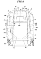
- FIG. 6 is a front view of the backrest 4
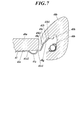
- FIG. 7 is a cross-sectional view of the cross section along the line VII-VII shown in FIG.
- beads 41e are formed on the left and right sides of the front surface and the rear surface of the main body portion 41a.
- the bead 41e is recessed on the front surface of the main body 41a, and is provided in a convex shape on the rear surface of the main body 41a.
- the bead 41e extends in the vertical direction.
- the extending portion 41b extends obliquely forward from the side edge portion 41e1 of the bead 41e.
- the end of the upper wire 43 that supports the upper portion of the pressure receiving member 41 is fixed to the side frame 40b, and the end of the lower wire 44 that supports the lower portion of the pressure receiving member 41 can be moved back and forth by the swing member 45a. Since the pressure receiving member 41 is displaced upward, the displacement toward the rear is smaller as it goes upward, and the displacement toward the lower side is larger.
- the pressure receiving member 41 In a state where the load toward the rear does not act on the pressure receiving member 41 and the pressure receiving member 41 is not retracted (hereinafter referred to as a natural state), the pressure receiving member 41 is tilted rearwardly upward, and the main body of the pressure receiving member 41 The part 41a and the extension parts 41b and 41b are inclined backward and upward.
- FIG. 5 is a front view of the cushion pad 48
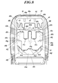
- FIG. 8 is a partial cross-sectional rear view of the backrest 4 in a state in which the cushion pad 48 is broken along a vertical cross section.
- the cushion pad 48 is made of a cushion material such as a foamed urethane foam material.
- the cushion pad 48 covers the frame 40 and the pressure receiving member 41 at least from the front of the frame 40 and the pressure receiving member 41 to the left side, the right side, and the upper side of the frame 40. Further, the cushion pad 48 may cover the frame 40 and the pressure receiving member 41 from behind the frame 40 and the pressure receiving member 41.
- the cushion pad 48 has a back support portion (center portion) 48a and left and right bank portions (side portions) 48b and 48b.
- the back support 48 a is the central part of the cushion pad 48
- the left bank 48 b is the left part of the cushion pad 48
- the right bank 48 b is the right part of the cushion pad 48.
- the back support portion 48a and the bank portions 48b, 48b are integrally formed, the right bank portion 48b is provided on the right side of the back support portion 48a, and the left bank portion 48b is provided on the left side of the back support portion 48a.
- the bank portions 48b and 48b are provided so as to bulge forward from the left and right sides of the front surface of the back support portion 48a (see FIG. 7), and the boundary between the front surfaces of the bank portions 48b and 48b and the front surface of the back support portion 48a. Is a valley line.
- grooves 48c, 48c, and 48d are formed on the front surface of the cushion pad 48.
- the grooves 48c and 48c extend in the vertical direction along the boundary between the bank portions 48b and 48b and the back support portion 48a.
- the groove 48d is formed slightly above the central portion of the front surface of the back receiving portion 48a and extends to the left and right.
- the left end of the groove 48d communicates with the left groove 48c, and the right end of the groove 48d communicates with the right groove 48c.
- Slits 48e and 48f are formed at the bottom of the right groove 48c.
- the slits 48e and 48f penetrate from the bottom of the groove 48c to the back side of the back receiving portion 48a and the bank portions 48b and 48b.
- the slits 48e and 48f extend along the groove 48c and are elongated vertically.
- the slit 48e is positioned above the slit 48f, the slit 48e is positioned slightly above the center of the back support 48a, and the slit 48f is positioned below the center of the back support 48a.
- Slits 48e and 48f are also formed at the bottom of the left groove 48c. Since the slit 48e and the groove 48c are formed along the boundary between the back receiving portion 48a and the bank portions 48b, 48b, the back receiving portion 48a is easily retracted when the back receiving portion 48a is pushed backward.
- the back receiving portion 48a covers the lower frame 40c, the main body 41a of the pressure receiving member 41, the cross member 42, and the front surface of the upper frame 40a, and also covers the upper surface of the upper frame 40a.
- the left bank portion 48b covers the front surface of the left extension portion 41b and the front surface of the left side frame 40b, and covers the left side surface and the rear surface of the left side frame 40b. Further, the left bank portion 48b covers the upper surface of the left end portion of the upper frame 40a and the upper surface of the left side frame 40b.
- the right bank portion 48b covers the front surface of the right extension portion 41b and the front surface of the right side frame 40b, and covers the right side surface and the rear surface of the right side frame 40b. Further, the right bank portion 48b covers the upper surface of the right end portion of the upper frame 40a and the upper surface of the right side frame 40b.
- the left and right widths of the back support part 48a are shorter than the left and right intervals of the side frames 40b and 40b, and the back support part 48a is disposed between the side frames 40b and 40b when viewed from the front of the backrest 4. Further, the grooves 48c and 48c are located between the side frames 40b and 40b when viewed from the front of the backrest 4.
- the left and right widths of the main body 41a of the pressure receiving member 41 are shorter than the left and right intervals of the grooves 48c and 48c, the left and right intervals of the slits 48e and 48e, and the left and right intervals of the slits 48f and 48f. Therefore, the main body 41a of the pressure receiving member 41 is disposed between the grooves 48c and 48c, between the slits 48e and 48e, and between the slits 48f and 48f when viewed from the front of the backrest 4.
- the right extending portion 41b of the pressure receiving member 41 extends rightward from the right side portion of the main body portion 41a, and is provided so as to get over the right slit 48e on the back side of the back receiving portion 48a and the bank portion 48b. Yes. Similarly, the left extension 41b is provided so as to get over the left slit 48e.
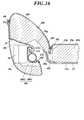
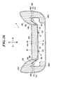
- a recess 48g is formed in a portion of the back side (inner side) surface of the right bank portion 48b facing the right extension portion 41b, and the recess 48g A stepped portion 48h, which is an edge on the right side (side side), protrudes rearward and obliquely right (side) from the bottom of the recess 48g.
- the right extending portion 41b contacts the left portion of the back side (inside) surface of the right bank portion 48b in the right concave portion 48g.
- the tip (front end, extension end) 41b1 (see FIG. 7) of the right extension portion 41b abuts on the back side (inside) surface of the right bank portion 48b in the right recess 48g.
- the left extending portion 41b also contacts the left portion of the back surface of the back support portion 48a and also contacts the right portion of the back side (inside) surface of the left bank portion 48b.
- a concave portion 48g is formed in a portion of the back side (inner side) surface of the left bank portion 48b that faces the left extending portion 41b, and a step portion that becomes an edge on the left side (side side) of the concave portion 48g. 48h protrudes rearward and diagonally left (side) from the bottom of the recess 48g. Accordingly, the left extension 41b contacts the left part of the back (inside) surface of the left bank 48b in the left recess 48g. The tip 41b1 of the left extension 41b also abuts on the back (inside) surface of the left bank 48b in the left recess 48g.
- the concave portion 48g is connected to the slit 48e, the concave portion 48g is provided along the edge of the slit 48e on the bank portion 48b side, and the concave portion 48g is provided so as to spread from the edge of the slit 48e on the bank portion 48b side. It has been.
- the range in which the recess 48g is formed is from the position in front of the side frame main body 40b2 to the slit 48e.
- the part where the extension part 41b is accommodated in the recess 48g and the extension part 41b contacts the surface on the back side of the bank part 48b is the bottom of the recess 48g.
- the stepped portion 48h extends rearward from the extending portion 41b, and the rear apex portion of the stepped portion 48h is located behind the lateral end of the extending portion 41b. Since the stepped portion 48h protrudes rearward and obliquely to the side, the stepped portion 48h is avoided from the track of the extending portion 41b when the pressure receiving member 41 moves backward.
- the length in the vertical direction of the recess 48g is longer than the length in the vertical direction of the extension 41b, and a gap 48i is secured between the upper edge of the extension 41b and the inner peripheral wall surface on the upper side of the recess 48g.
- a gap 48j is secured between the lower edge of the extending portion 41b and the inner peripheral wall surface below the concave portion 48g.
- the lower gap 48j is larger than the upper gap 48i.
- the vertical length of the slit 48e is longer than the vertical length of the extending portion 41b. Furthermore, the length of the slit 48e in the vertical direction is longer than the length of the concave portion 48g in the vertical direction.
- the upper part of the slit 48e is notched upward from the inner peripheral wall surface on the upper side of the concave portion 48g, and the upper end of the slit 48e is located above the inner peripheral wall surface on the upper side of the concave portion 48g.
- the lower portion of the slit 48e is cut downward from the lower inner peripheral wall surface of the recess 48g, and the lower end of the slit 48e is positioned above the lower inner peripheral wall surface of the recess 48g.
- the concave portion 48g is formed on the back side surface of the bank portion 48b, the bank portion 48b is thinned at the portion where the concave portion 48g is formed, and the thinned portion is referred to as a thin portion 48k. Therefore, a gap between the thin portion 48k and the side frame main body portion 40b2 is ensured by the concave portion 48g.
- the thin portion 48k is formed to be harder than the other portion of the bank portion 48b. The reason why the thin portion 48k is hard is that the void does not enter the thin portion 48k when the cushion pad 48 is foam-molded, and the porosity of the thin portion 48k is lower than that of other portions.
- the end portion 48k1 of the thin portion 48k is in contact with the extending portion 41b, and the side edge portion 41e1 of the bead 41e is the side edge portion on the back surface of the back support portion 48a (the edge portion on the slit 48e side). Abut.
- the contact portion between the end portion 48k1 of the thin portion 48k and the extending portion 41b is in front of the contact portion between the side edge portion 41e1 of the bead 41e and the side edge portion of the back surface of the back receiving portion 48a.
- the skin 49 is suspended from the surface of the cushion pad 48.
- Suspension means that the surface 49 of the cushion pad 48 is stretched along the surface on the front side of the cushion pad 48 with the skin 49 covering the surface of the cushion pad 48 stretched.
- a plurality of first engaging members are provided on the back surface of the skin 49, and these first engaging members are arranged along the grooves 48c, 48c, and 48d so as to avoid the slits 48e.
- a plurality of second engaging members are also embedded in the bottoms of the grooves 48c, 48c, and 48d, and these are arranged along the grooves 48c, 48c, and 48d so as to avoid the slit 48e.
- the first engagement member With the skin 49 being stretched, the first engagement member is inserted into the grooves 48c, 48c, and 48d, and the tension of the skin 49 is maintained by engaging the first engagement member and the second engagement member. . Thereby, the skin 49 is suspended on the surface of the cushion pad 48.
- the skin 49 has a plurality of skin parts, and the skin 49 is provided in a bag shape by sewing these skin parts together. Specifically, the skin 49 has a front skin part 49a, a pair of left and right bank skin parts 49b and 49b, a pair of left and right side skin parts 49c and 49c, and a back skin part.
- the bank surface parts 49b and 49b are sewn to the left and right sides of the front skin part 49a, the left side skin part 49c is sewn to the left side of the left bank surface part 49b, and the right side skin part 49c is The skin part 49b is sewn on the right side, the back skin part is sewn on the upper side of the front skin part 49a, the back skin part is folded back behind the front skin part 49a, and the side skin parts 49c, 49c are back. Fastened to the left and right sides of the skin with fasteners.
- the cushion pad 48 and the frame 40 are put in the skin 49, and the cushion pad 48 is encapsulated by the skin 49.
- the front skin part 49a covers the front surface of the back support portion 48a
- the bank surface skin part 49b covers the front surface of the bank portion 48b
- the side skin part 49c covers the side surface of the bank portion 48b from the back surface
- the rear skin part is covered.
- the back side of the frame 40 is covered.
- a pair of left and right draw bands (pull members) 49e, 49e are connected to the back surface of the skin 49 by stitching, adhesion, welding, or the like.
- a pair of left and right draw bands (pull members) 49e, 49e are connected to the seam of the front skin part 49a and the bank surface skin parts 49b, 49b by stitching, adhesion, welding, etc., inside the skin 49.
- the draw band 49e is sewn to the front skin part 49a and the bank surface skin part 49b while being sandwiched between the terminal of the front skin part 49a and the terminal of the bank surface skin part 49b.
- the connecting portion between the skin 49 and the draw bands 49e, 49e is a position overlapping the slits 48e, 48e.
- the draw bands 49e, 49e are passed through the slits 48e, 48e from the front side to the back side of the back support part 48a and the bank parts 48b, 48b, and the skin 49 is pulled back by the draw bands 49e, 49e, 49e are attached to each other by a hook-and-loop fastener 49g on the back side of the back support 48a.
- the draw bands 49e and 49e are stretched, the back receiving portion 48a is tightened and compressed by the draw bands 49e and 49e, and the widths of the slits 48e and 48e are expanded by the draw bands 49e and 49e.
- the epidermis 49 is hung on the surface of the cushion pad 48, and the tension of the epidermis 49 is maintained.
- a recess 48m is formed in a portion of the back surface of the back receiving portion 48a that overlaps the surface fastener 49g, and the surface fastener 49g is prevented from being sandwiched between the back receiving portion 48a and the pressure receiving member 41. . Therefore, it is possible to suppress the generation of noise due to the hook-and-loop fastener 49g contacting the back receiving portion 48a and the pressure receiving member 41.
- the occupant sits on the bottom seat 3 and leans the upper body 99a on the backrest 4 as shown in FIG. 9A.
- the passenger often takes a posture in which the head is slightly separated from the headrest.
- the back of the occupant is received on the front surface of the back support 48a, and the back support 48a is elastically compressed. Further, the left and right side portions (mainly shoulders, scapula, flank, upper arm, etc.) of the occupant's upper body 99a are received by the bank portions 48b and 48b, and the bank portions 48b and 48b are slightly compressed. Then, the extension parts 41b and 41b mainly support the rear part of the side part corresponding to the chest height in the upper body of the occupant through the bank parts 48b and 48b.
- the bank portions 48b and 48b (thin portions 48k and 48k) are supported by the extending portions 41b and 41b from the back side, even if the thin portions 48k and 48k are pushed backward by the occupant's upper body 99a, the thin portion 48k. , 48k will not be greatly bent backward. Therefore, it is possible to suppress the holdability from the side of the occupant's upper body 99a from being lowered by the recessed portion 48g by the extending portion 41b of the pressure receiving member 41. Moreover, even if the thin portions 48k and 48k are harder than other portions, or even if the cushioning properties of the thin portions 48k and 48k are low, the cushioning properties can be supplemented by the extending portions 41b and 41b.
- the slits 48e and 48e are formed, the thin portions 48k and 48k are easily bent backward.
- the extending portions 41b and 41b straddle the slits 48e and 48e and receive the thin portions 48k and 48k from the rear, the thin portions 48k and 48k are moved backward by the upper body 99a of the occupant leaning on the backrest 4. Even if it is pushed, the thin-walled portions 48k, 48k are not greatly bent backward. Therefore, holdability from the side of the occupant's upper body 99a can be secured.
- crew's back is supported by the surface by the pressure receiving member 41, a passenger
- the extended portion 41b is in contact with the back side of the bank portion 48b (thin wall portion 48k). Therefore, as soon as the occupant drowns on the backrest 4, the occupant's upper body 99a is held from the side by the bank portion 48b. Moreover, even if the weight of the occupant is light, the holdability from the side of the occupant's upper body 99a can be ensured.
- the vehicle When the rear part of the host vehicle (referring to the vehicle provided with the seat 1) collides with another vehicle or an obstacle, or when the other vehicle collides with the rear part of the host vehicle from the rear of the host vehicle, the vehicle heads backward. Inertial force acts on the occupant and the seat 1. Then, the back receiving portion 48a and the pressure receiving member 41 are retracted (see FIG. 9B), and the upper body 99a sinks backward while the back of the occupant who has been drowning on the backrest 4 is curled like a back of the back. At the same time, the back of the occupant hits the headrest 6.
- the occupant's upper body 99a is curled up like a stoop, the occupant's back head is received by the headrest 6, so that the occupant's neck can be prevented from warping back, and the occupant's neck is burdened. Can be reduced.
- the upper body 99a of the occupant is in a state of being curled like a stoop. Prone. As the occupant's upper body 99a curls and retreats, the occupant's rear head is received by the headrest 6, so that the occupant's neck can be prevented from warping backwards, reducing the burden on the occupant's neck. can do.
- the back receiving portion 48a and the pressure receiving member 41 are largely retracted.
- the thin portions 48k, 48k of the bank portions 48b, 48b are pushed rearward by the left and right side portions (mainly shoulders, shoulder blades, flank, upper arms, etc.) of the occupant's upper body 99a, and the thin portions of the bank portions 48b, 48b.
- the portions 48k and 48k bend backward.
- the extending portions 41b and 41b of the pressure receiving member 41 are also pushed backward by the thin portions 48k and 48k, and the extending portions 41b and 41b are elastically bent backward.
- the contact portion between the end portion 48k1 of the thin portion 48k and the extending portion 41b is located before the contact portion between the side edge portion 41e1 of the bead 41e and the side edge portion of the back surface of the back receiving portion 48a (see FIG. 7).
- the extending portion 41b is easily bent backward. Further, since the extended portion 41b extends obliquely forward from the side edge portion 41e1 of the bead 41e (see FIG. 7), the extended portion 41b extends with the side edge portion 41e2 on the opposite side of the bead 41e as a fulcrum.
- the protruding portion 41b is easily bent backward.
- the back support portion 48a and the main body portion 41a of the pressure receiving member 41 are easily retracted, and the thin portions 48k of the bank portions 48b and 48b. , 48k are easily bent backward, and the extending portions 41b, 41b of the pressure receiving member 41 are easily retracted. It can suppress that the upper body 99a of a passenger
- the cushion pad 48 can suppress the occupant's upper body 99a from sinking backward.
- the bank parts 48b and 48b reduce the extension parts 41b and 41b from retreating and the extension parts 41b and 41b from bending backward. Not. Therefore, it can suppress that the passenger
- the lower part of the slit 48e is notched downward from the lower inner peripheral wall surface of the concave part 48g, the lower part of the back support part 48a is easily retracted. Therefore, even if the pressure displacement of the pressure receiving member 41 increases as it goes downward, the back receiving portion 48 a moves backward together with the pressure receiving member 41.
- the stepped portion 48h protrudes obliquely to the rear side, the stepped portion 48h bends sideways so that the recessed portion 48g is opened when the thin-walled portions 48k, 48k of the bank portions 48b, 48b are bent backward. Therefore, it is not reduced by the step portions 48h and 48h that the extending portions 41b and 41b are retracted and bent backward. Therefore, it can suppress that the passenger
- the stepped portion 48h protrudes diagonally rearward so as to avoid the locus of the tip 41b1 (see FIG. 7) of the extended portion 41b when the extended portion 41b is pushed by the thin portion 48k and bent backward. For this reason, the stepped portion 48h does not reduce the extension portion 41b from being retracted and bent backward.
- the attachment portion 43a Since the attachment portion 43a is attached to the vertical pipe portion 40b1 at a position avoiding the front end of the vertical pipe portion 40b1, the distal end of the extension portion 41b is bent when the extension portion 41b is pushed and bent backward by the thin portion 48k. 41b1 does not hit the attachment portion 43a. Therefore, it is not reduced by the attachment part 43a that the extension part 41b is retracted and bent backward.
- the thin portions 48k and 48k are harder than other portions, the inertia force when the occupant's upper body 99a sinks rearward is not distributed over the entire bank portions 48b and 48b, and the thin portions 48k and 48b of the bank portions 48b and 48b. 48k tends to bend backwards. Therefore, it can suppress that the passenger
- the seat 1 is a vehicle seat used in an automobile, but may be a seat used in other vehicles (railway vehicles, ships, aircrafts, etc.).
- Appendix 1 Left and right side frames arranged side by side, A pressure receiving member that is provided between the side frames and is swingable back and forth; A cushion pad covering the front surface of the side frame and the front surface of the pressure receiving member, The pressure receiving member is The main body, Left and right extending portions extending left and right from the left and right side portions of the main body, respectively, The cushion pad is A back support portion covering the front surface of the main body portion; A bank portion provided on both right and left sides of the back support portion, provided to bulge forward from both left and right sides of the front surface of the back support portion, and covering the front surface of the extension portion and the front surface of the side frame; Have A recess is formed in a portion of the back side surface of the bank portion that faces the extension portion. Seat backrest.
- Appendix 2 The extending portion abuts on the back surface of the bank in the recess, The seat backrest according to appendix 1.
- Appendix 3 The extension is housed in the recess, The extension part is separated from the inner peripheral wall surface of the recess, The seat backrest according to appendix 1 or 2.
- Appendix 5 Of the bank portion, the portion where the recess is formed is harder than other portions, The seat backrest according to any one of appendices 1 to 4.
- Appendix 6 A stepped portion that becomes an edge on the side of the concave portion protrudes obliquely rearward from the bottom of the concave portion, The seat backrest according to any one of appendices 1 to 5.
- the stepped portion is obliquely rearward and sideward so as to avoid the locus of the tip of the extending portion when the extending portion is pushed backward by a portion of the bank portion where the recessed portion is formed and bent backward. Protruding, The seat backrest according to appendix 6.
- Appendix 8 Left and right slits formed in the cushion pad at the boundary between the back support part and the bank part penetrate from the front side to the back side of the cushion pad, The backrest of the seat according to any one of appendices 1 to 7, wherein the extension part gets over the slit on the back side of the back support part and the bank part.
- the recess is provided along an edge on the bank portion side of the slit, and the recess is provided so as to spread laterally from the bank side edge of the slit, The slit is provided so as to cut out downward from the inner peripheral wall surface on the lower side of the recess.
- the seat backrest according to appendix 8 or 9.
- Appendix 11 An epidermis covering the cushion pad; Left and right pulling members provided on the back side of the skin, A hook-and-loop fastener provided on the pulling member, The pulling member is routed to the back side of the back support part through the slit, the back support part is tightened by the pulling member, the pulling member is attached by the hook-and-loop fastener, A depression is formed in a portion of the back surface that overlaps the hook-and-loop fastener, The seat backrest according to any one of appendices 8 to 10.
- the stepped portion protrudes diagonally rearward, so that when the portion where the recess is formed bends backward, the stepped portion is bent sideways so that the recess is opened. Mu For this reason, the stepped portion does not reduce the extension portion from retreating and bending backward. Therefore, it can suppress that an occupant's upper body sinks back by the extension part.
- FIG. 10 is a perspective view of a seat 1A according to the second embodiment of the present invention. Parts corresponding to each other between the sheet 1A of the second embodiment and the sheet 1 of the first embodiment are denoted by the same reference numerals. In the case where the portions corresponding to each other between the sheet 1A of the second embodiment and the sheet 1 of the first embodiment are identical and provided in the same manner, description thereof will be omitted as much as possible. Below, the part which is different between the sheet
- This seat 1A is also a vehicle seat (particularly a vehicle seat).
- the slide rail 2, the bottom seat 3, the reclining mechanism 5, and the headrest 6 of the seat 1A are provided in the same manner as the slide rail 2, the bottom seat 3, the reclining mechanism 5, and the headrest 6 of the seat 1 of the first embodiment, respectively. .
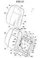
- FIG. 11 is an exploded perspective view of the backrest 4.
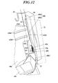
- FIG. 12 is a perspective view showing the side frame 40b of the backrest 4 and the like.
- FIG. 13 is a side view of the backrest 4.
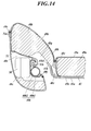
- FIG. 14 is a cross-sectional view of the left cross section of the backrest 4 as viewed from above.
- FIG. 15 is a partial cross-sectional rear view of the backrest 4 in a state where the cushion pad 48 is broken along a vertical cross section.
- the backrest 4 includes a frame 40, a pressure receiving member 41, a cross member 42, an upper wire 43, a lower wire 44, a cushion pad 48, and a skin 49 as in the case of the first embodiment. Further, the backrest 4 includes an airbag module 50, a baffle (guide cloth) 51, two upper and lower baffle attachment members 52 and 52, a side support member 40d, and the like.
- the frame 40 in the second embodiment is provided in the same manner as the frame 40 in the first embodiment.
- the pressure receiving member 41 in the second embodiment is provided in the same manner as the pressure receiving member 41 in the first embodiment.
- the beads 41b4 and 41b4 extended to the left and right are formed in the extension parts 41b and 41b.
- the beads 41b4 and 41b4 are provided in a concave shape on the front surfaces of the extending portions 41b and 41b, and are provided in a convex shape on the rear surfaces of the extending portions 41b and 41b.
- the rigidity of the extending portions 41b and 41b is improved by the beads 41b4 and 41b4.
- the beads 41b4 and 41b4 may be provided in a convex shape on the front surfaces of the extending portions 41b and 41b, and may be provided in a concave shape on the rear surfaces of the extending portions 41b and 41b. Also in the first embodiment, the beads 41b4 and 41b4 may be formed in the extending portions 41b and 41b.
- the cushion pad 48 in the second embodiment is also provided in the same manner as the cushion pad 48 in the first embodiment.
- a storage space 48 s for storing the airbag module 50 is formed in the left part of the cushion pad 48.
- a storage space 48s is formed on the left side surface of the left bank portion 48b, and the storage space 48s penetrates from the left side surface of the bank portion 48b to the inner surface thereof.
- the airbag module 50 is stored in the storage space 48s.
- the airbag module 50 is embedded in the left portion of the cushion pad 48 so as to be exposed on the left side surface of the cushion pad 48, and the skin 49 covers the cushion pad 48 and the airbag module 50.
- the left bank surface skin part 49b covers the airbag module 50
- the storage space 48s is closed by the left bank surface skin part 49b.
- the airbag module 50 will be described. As shown in FIGS. 10 to 15, the airbag module 50 is attached to the outer (left) side surface of the left side frame 40b.
- the airbag module 50 includes at least an inflator and an airbag, and a retainer, a lid, an impact sensor, a control circuit, and the like are incorporated in the airbag module 50 as necessary.
- a signal from the impact sensor is input to the inflator via the control circuit, the inflator is ignited by the signal, and the airbag is instantly inflated by the gas generated from the inflator.
- the side support member 40d is attached to the front end of the right side frame 40b by welding or the like.
- the side support member 40d is formed of a rod member bent in a hook shape (fishhook shape). That is, the side support member 40d includes a vertical portion 40d1 that extends vertically away from the front end of the side frame 40b, and a bent portion 40d2 that is bent backward from the upper end of the vertical portion 40d1 and further bent downward.
- the rear end of the bent portion 40d2 is fixed to the upper side of the front end of the side frame main body portion 40b2 by welding or the like, and the lower end portion of the vertical portion 40d1 is fixed to the upper side of the front end of the overhang portion 40b3 by welding or the like. Therefore, as viewed from the side, a region 40d3 surrounded by the front end of the side frame 40b and the side support member 40d is formed between the vertical portion 40d1 and the front end of the side support member 40d.
- the distal ends (front end, extended end) 41b1 of the left and right extending portions 41b and 41b are disposed in a region 40d3 surrounded by the front end of the side frame 40b and the side support member 40d.
- the right bank portion 48b of the cushion pad 48 covers the front surface of the side support member 40d.
- the side support member 40d supports the right bank portion 48b from the rear and bulges the bank portion 48b forward. Note that the side support member 40d may also be provided in the first embodiment.
- the skin 49 and its suspension will be described.
- the inside of the skin 49 is stopped by the cushion pad 48 by an engaging member such as a C ring.
- a hook 49f is provided at the terminal of the side skin part 49c, and the hook 49f is hooked on the side frame 40b.
- a pair of left and right draw bands (pull members) 49e, 49e are sewn and bonded to the seam of the front skin part 49a and the bank surface skin parts 49b, 49b inside the skin 49.
- the draw bands 49e, 49e are sewn to the front skin part 49a and the bank skin parts 49b, 49b while being sandwiched between the terminal of the front skin part 49a and the terminals of the bank skin parts 49b, 49b.
- the connecting portion between the skin 49 and the draw bands 49e, 49e is a position overlapping the slits 48e, 48e.
- the draw bands 49e, 49e are passed through the slits 48e, 48e from the front side to the back side of the back support part 48a and the bank parts 48b, 48b, and the skin 49 is pulled back by the draw bands 49e, 49e, 49e are attached to each other by a hook-and-loop fastener 49g on the back side of the back support 48a.
- the draw bands 49e and 49e are stretched, and the back receiving portion 48a is fastened by the draw bands 49e and 49e. Thereby, the epidermis 49 is hung on the surface of the cushion pad 48, and the tension of the epidermis 49 is maintained.
- a recess 48m is formed in a portion of the back surface of the back receiving portion 48a that overlaps the surface fastener 49g, and the surface fastener 49g is prevented from being sandwiched between the back receiving portion 48a and the pressure receiving member 41. . Therefore, it is possible to suppress the generation of noise due to the hook-and-loop fastener 49g contacting the back receiving portion 48a and the pressure receiving member 41.
- the skin 49 may be hung on the surface of the cushion pad 48 by the first engaging member 49d and the second engaging member 48u instead of the draw bands 49e, 49e. That is, a plurality of first engagement members 49d are provided inside the skin 49 and in the seam of the front skin part 49a and the bank surface skin part 49b, and these first engagement members 49d are arranged along the grooves 48c. ing.
- the second engaging member 48u is also provided in the portion of the groove 48c that overlaps the slits 48e, 48e, and the first engaging member 49d is inserted into the grooves 48c, 48c in a state where the skin 49 is stretched. The engaging member 49d and the second engaging member 48u are engaged.
- a rupture scheduled portion 49 t is formed in the epidermis 49.
- the position where the expected rupture portion 49t is formed is the front side of the side surface of the left bank portion 48b.
- a seam of the left side skin part 49c and the left bank surface part 49b is a rupture scheduled portion 49t.
- the rupture scheduled portion 49t has a lower strength than other portions of the epidermis 49, and the strength of the seam of the planned rupture portion 49t is lower than the strength of the other seams of the epidermis 49.
- the seam of the planned rupture portion 49t has a strength capable of being broken by a tensile force due to the expansion of the airbag of the airbag module 50 while maintaining a strength that can withstand normal usability.
- one end 51 a of the webbing 51 is connected to the inner surface of the skin 49.
- one terminal 51a of the buff 51 is sewn to the left bank surface skin part 49b and the side skin part 49c at the planned rupture portion 49t.
- FIG. 17 is a cross-sectional view showing the webbing attachment member 52 attached to the side frame 40b.
- the baffle attachment member 52 is a clip made of a resin material.
- the baffle attachment member 52 has a spiral portion 52a, a spiral notch 52b, a locking piece portion 52c, and an arc-shaped notch 52d.
- the spiral part 52a is spirally wound with a gap, and the gap surrounded by the spiral part 52a is the spiral notch 52b, and the spiral notch 52b opens at the outermost part of the spiral part 52a.
- the locking piece part 52c extends along the outermost peripheral part of the spiral part 52a from a portion closer to the center of the outermost peripheral part of the spiral part 52a. There is a gap between the locking piece 52c and the spiral notch 52b, and the gap is an arc-shaped notch 52d, and the arc-shaped notch 52d opens at the protruding end of the locking piece 52c.
- the front end portion 40b5 of the side frame 40b (particularly, the side frame main body portion 40b2) is curved in a hook shape (hereinafter, the curved portion is referred to as a hook-like portion 40b5), and the tip portion of the hook-like portion 40b5 is inserted into the arc-shaped notch 52d.
- the spiral portion 52a is arranged inside the flange portion 40b5, and the tip portion of the flange portion 40b5 is sandwiched between the spiral portion 52a and the locking piece portion 52c.
- the baffle attachment member 52 is attached to the side frame 40b.
- the end of the force cloth 51 is inserted into the spiral notch 52b, the end of the force cloth 51 is wound along the spiral notch 52b, and the end of the force cloth 51 is sandwiched between the spiral portions 52a.
- the webbing attachment member 52 is attached to the end of the webbing 51.
- a plate-like or rod-like filling member may be inserted into the spiral notch 52b, and the end of the baffle 51 may be sandwiched between the spiral portions 52a more powerfully.
- the webbing 51 is stretched from the planned rupture portion 49 t to the webbing attachment members 52 and 52 via the periphery of the airbag module 50 in a stretched state.
- the baffle 51 is suspended from the front side of the side surface of the left bank portion 48b to the edge of the storage space 48s, and further suspended from the side surface of the bank portion 48b, and further from the edge of the storage space 48s to the storage space 48s. It is passed through the side frame 40b.
- the power cloth 51 is made of a cloth-like material having small stretchability.
- the webbing 51 is a guide member for guiding the deployment direction of the airbag module 50.
- the airbag of the airbag module 50 is inflated, the airbag is guided by the webbing 51 to the expected rupture portion 49t. Therefore, when the airbag is inflated, the airbag breaks through the expected rupture portion 49t and inflates forward.
- the position where the bundling attachment members 52 and 52 are provided will be described.
- the webbing attachment members 52, 52 are provided at positions avoiding the locus of the left extension 41b when the pressure receiving member 41 swings back and forth (see FIGS. 11 to 14).
- the lower baffle attachment member 52 has a left extending portion when the pressure receiving member 41 is in a natural state (a state where a load toward the rear does not act on the pressure receiving member 41 and the pressure receiving member 41 is not retracted). It is attached to the side frame 40b at a position before the position of the tip 41b1 of 41b (see FIGS. 13 and 14).
- the upper baffle attachment member 52 is attached to the side frame 40b at a position away from the lower end 41b2 of the left extending portion 41b when the pressure receiving member 41 is in a natural state (FIGS. 11 to 11). 13).
- the lower baffle attachment member 52 is attached to the side frame 40b at a position avoided from the lower end 41b2 of the left extension 41b when the pressure receiving member 41 is in a natural state (see FIGS. 11 to 13). ).
- the upper baffle attachment member 52 is attached to the side frame 40b at a position away from the upper end 41b3 of the left extension 41b when the pressure receiving member 41 is in a natural state (FIGS. 11 to 11). 13).
- the baffle attachment members 52 and 52 are respectively located at the position avoided from the left extension 41b and the position avoided from the left extension 41b. It is attached to the frame 40b.
- the baffle attachment members 52 and 52 are attached to the side frame 40b at a position avoiding up and down from the frontmost portion 40b4 of the overhang portion 40b3 (see FIG. 13). Further, the baffle attachment members 52 and 52 are attached to the side frame 40b at positions avoiding above or below the beads 41b4 and 41b4 when the pressure receiving member 41 is in a natural state (see FIG. 12).
- the upper webbing attachment member 52 is arranged above the left extension 41b, and the lower webbing attachment 52 is arranged below the left extension 41b. Is separated from the top and bottom, so that the webbing 51 is stably attached.
- the occupant sits on the bottom seat 3 and leans his upper body on the backrest 4.
- the passenger often takes a posture in which the head is slightly separated from the headrest.
- the back of the occupant is received on the front surface of the back support 48a, and the back support 48a is elastically compressed. Further, the left and right side portions (mainly shoulders, scapula, flank, upper arm, etc.) of the upper body of the occupant are received by the bank portions 48b and 48b, and the bank portions 48b and 48b are slightly compressed. Since the bank portions 48b and 48b (thin portions 48k and 48k) are supported from the inside by the extending portions 41b and 41b, even if the thin portions 48k and 48k are pushed backward by the upper body of the occupant, the thin portions 48k and 48b, 48k does not bend greatly backwards. Therefore, it is possible to suppress the holdability from the side of the upper body of the occupant from being lowered by the recessed portion 48g by the extending portion 41b of the pressure receiving member 41.
- the slits 48e and 48e are formed at the bottoms of the grooves 48c and 48c, the thin portions 48k and 48k are easily bent backward.
- the extending portions 41b and 41b straddle the slits 48e and 48e and receive the thin portions 48k and 48k from the rear, the thin portions 48k and 48k are pushed backward by the upper body of the occupant leaning on the backrest 4. Even if it is done, the thin-walled parts 48k, 48k will not bend greatly backwards. Therefore, the holdability from the side of the upper body of the occupant can be ensured.
- the extended portion 41b is in contact with the inside of the bank portion 48b (thin wall portion 48k). Therefore, as soon as the occupant drowns on the backrest 4, the upper body of the occupant is held from the side by the bank portion 48b. Moreover, even if the weight of the occupant is light, the holdability from the side of the occupant's upper body can be ensured.
- the vehicle When the rear part of the retreating vehicle (referred to as a vehicle provided with the seat 1A) collides with another vehicle or an obstacle, or when the other vehicle collides with the rear part of the own vehicle from the rear of the own vehicle, the vehicle heads backward. Inertial force acts on the occupant and the seat 1A. Then, the back receiving portion 48a and the pressure receiving member 41 move backward, and the upper body sinks backward while the back of the occupant who has been drowning on the backrest 4 is curled like a stoop. At the same time, the back of the occupant hits the headrest 6.
- the back of the occupant's head is received by the headrest 6, so that the occupant's neck can be prevented from warping back, and the burden on the occupant's neck can be reduced. Can be reduced.
- the back receiving portion 48a and the pressure receiving member 41 are largely retracted.
- the thin portions 48k, 48k of the bank portions 48b, 48b are pushed rearward by the left and right side portions (mainly shoulders, shoulder blades, flank, upper arms, etc.) of the occupant's upper body, and the thin portions of the bank portions 48b, 48b.
- the portions 48k and 48k bend backward.
- the extension portions 41b and 41b of the pressure receiving member 41 are also pushed backward by the thin portions 48k and 48k, and the extension portions 41b and 41b bend backward.
- Concave portions 48g and 48g are formed on the back surface of the bank portions 48b and 48b, and a space for retreating the thin portions 48k and 48k and the extending portions 41b and 41b of the pressure receiving member 41 is secured on the back side of the bank portions 48b and 48b. Therefore, it can suppress that the upper part of a passenger
- the swing members 45a and 45a swing backward against the tensile load of the tension springs 45d and 45d, and the pressure receiving member 41 further moves backward.
- the oscillating members 45a and 45a oscillate backward, the displacement of the pressure receiving member 41 toward the rear is smaller as it goes upward, and is larger as it goes downward.
- the baffle attachment members 52 and 52 avoid the locus of the left extension portion 41b, so the left extension portion 41b hits the baffle attachment members 52 and 52. This can be suppressed, and the reduction of the backward extension of the left extension 41b and the pressure receiving member 41 can be suppressed. Therefore, the retreat distance of the pressure receiving member 41 can be ensured, and it can be suppressed that the upper body of the occupant sinks backward is reduced by the baffle attachment members 52 and 52.
- the lower bedding attachment member 52 is attached to the side frame 40b in front of the tip 41b1 of the left extension portion 41b, the backward extension of the left extension portion 41b is reduced by the lower bedding attachment member 52. Can be further suppressed. Therefore, the retreat distance of the pressure receiving member 41 can be further ensured.
- the left extension Since the upper webbing attachment member 52 is arranged above the left extension 41b and the lower webbing attachment 52 is arranged below the left extension 41b, the left extension The retreat of 41b can be further suppressed from being reduced by the baffle attachment members 52, 52, and the retreat distance of the pressure receiving member 41 can be further ensured. Furthermore, the degree of freedom of the shape of the extension part 41b is expanded, and the extension part 41b can be made larger. The larger the extension portion 41b, the higher the holdability from the side of the occupant's upper body.
- the baffle attachment members 52 and 52 are attached to the side frame 40b at a position avoiding the up and down from the maximum overhang portion 40b4 of the overhang portion 40b3, the retraction of the left extension portion 41b is caused by the baffle attachment members 52 and 52. It is possible to further suppress the reduction. Furthermore, the degree of freedom of the shape of the extension part 41b is expanded, the extension part 41b can be made larger, and the holdability from the side of the occupant's upper body can be enhanced.
- the tip 41b1 of the right extension 41b is disposed in the region 40d3 surrounded by the front end of the side frame 40b and the side support member 40d, even if the right extension 41b bends backward, the extension It can suppress that the protrusion part 41b hits the side support member 40d. Therefore, the retreat distance of the pressure receiving member 41 can be ensured, and the reduction of the upper body of the passenger by the side support member 40d can be suppressed.
- webbing attachment members 52 and 52 are clips, the webbing attachment members 52 and 52 can be reduced in size. For this reason, it is possible to suppress the extension portion 41 b from hitting the baffle attachment members 52, 52 when the pressure receiving member 41 is retracted.
- the upper baffle attachment member 52 is attached to the side frame 40b at a position avoiding the upper end 41b3 of the left extension portion 41b.
- the upper baffle attachment member 52 is positioned away from the lower end 41b2 of the left extension 41b when the pressure receiving member 41 is in the natural state, and the left extension It is attached to the side frame 40b at a position avoided from the upper end 41b3 of 41b (see FIG. 18). In other words, the vertical position of the upper webbing attachment member 52 is aligned with the vertical position of the left extension 41b.
- the positions where the beads 41b4 and 41b4 are formed are positions shifted upward and downward from the upper bundling attachment member 52. Therefore, it is possible to prevent the beads 41b4 and 41b4 from hitting the upper bundling attachment member 52 when the left extending portion 41b moves backward.
- one or two embroidery attachment members 52, 52 are attached to the left side frame 40b.
- the number of the bundling attachment members 52 is three or more. Even when the number of the bundling attachment members 52 is three or more, the side frame 40b is located at a position avoiding the locus of the left extension 41b when the pressure receiving member 41 swings back and forth. Is attached.
- the webbing attachment members 52 and 52 are made of resin and are clips that hold the hook-like portion 40b5 of the side frame 40b by the spiral portion 52a and the locking piece portion 52c. It was.
- the bedding attachment member 53 instead of the bedding attachment members 52, 52 bends a wire such as a hard steel wire, a piano wire, or a stainless wire. Listing wire.
- the baffle attachment member 53 is bent along the right side (inner side) and the front side of the left side frame 40b by bending backward from the upper and lower ends of the support part 53a and the support part 53a on the left front side of the side frame 40b.
- a pair of upper and lower arm portions 53b, 53b that extend and hook portions 53c, 53c bent in a hook shape from the rear ends of the arm portions 53b, 53b are provided.
- the baffle attachment member 53 is attached to the side frame 40b (particularly, the side frame main body portion 40b2) via a latch member 54 made of a metal bar or the like.
- the latch member 54 is welded to the rear end of the left side frame 40b (particularly, the side frame main body portion 40b2) and protrudes rightward from the side frame 40b.
- a portion of the latch member 54 that protrudes to the right from the side frame 40b is formed in a gate shape (for example, a U-shape, a U-shape, etc.), and the hook portions 53c and 53c of the baffle attachment member 53 are the latch members.
- the rear end portions of the arm portions 53b and 53b are attached to the left side frame 40b via the retaining member 54 by being hooked (or entangled) by the gate-shaped portion 54.
- the hook portions 53c and 53c of the baffle attachment member 53 are directly hooked to the right side (inside) of the rear end surface of the left side frame 40b, so that the rear end portions of the arm portions 53b and 53b are attached to the left side frame 40b. May be.
- the tension cloth 51 is stretched from the planned rupture portion 49t to the support portion 53a of the tension cloth attachment member 53 via the periphery of the airbag module 50 in a stretched state.
- the other end 51b of the force cloth 51 is folded and sewed by the support portion 53a, so that the end 51b is provided in a cylindrical shape, and the support portion 53a is inserted into the cylindrical portion.
- the other terminal 51b is hung on the support portion 53a.
- the baffle attachment member 53 is provided at a position that avoids the locus of the left extension 41b when the pressure receiving member 41 swings back and forth. Therefore, it is possible to suppress the backward extension of the left extension portion 41 b from being reduced by the baffle attachment member 53.
- the baffle attachment member 53 When viewed from the side, the baffle attachment member 53 is provided at a position away from the beads 41b4 and 41b4. That is, when viewed from the side, the arm portions 53b and 53b are avoided from the beads 41b4 and 41b4 up and down. Therefore, it is possible to suppress the beads 41b4 and 41b4 from hitting the forceps attaching member 53 when the left extending portion 41b moves backward.
- the upper arm portion 53b When viewed from the side, the upper arm portion 53b is in a position avoiding upward from the lower end 41b2 of the extension portion 41b, and the lower arm portion 53b is in a position avoiding downward from the lower end 41b2 of the extension portion 41b. Therefore, it is possible to further suppress the backward extension of the left extension 41b from being reduced by the webbing attachment member 53.
- the baffle attachment member 53 is positioned away from the maximum overhanging portion 40b4 of the overhanging portion 40b3. Therefore, it is possible to further suppress the backward extension of the left extension 41b from being reduced by the webbing attachment member 53.
- Appendix 1 Side frames arranged side by side, A pressure receiving member that is provided between the side frames and is swingable back and forth; An airbag module attached to the side frame; A cushion pad covering the front surface of the side frame and the front surface of the pressure receiving member; An epidermis covering the cushion pad; A bundling attachment member attached to the side frame; A webbing stretched from the back side of the skin to the webbing attachment member via the periphery of the airbag module;
- the pressure receiving member is The main body, Extending from the left and right sides of the main body to the left and right, respectively, The webbing attachment member is provided at a position that avoids the locus of the extension part associated with the back and forth swinging of the pressure receiving member. Seat backrest.
- the baffle attachment member is provided at a position in front of the front end of the extension part, The seat backrest according to appendix 1.
- Appendix 3 The extension part tilts backwards upward, The baffle attachment member is provided at a position avoiding above or below from the lower end of the extension part, The seat backrest according to appendix 1 or 2.
- the baffle attachment member is provided at a position avoided above or below the extension portion or at both of these positions, The seat backrest according to any one of appendices 1 to 3.
- Appendix 5 A bead is formed in the extension part, The vertical position of the baffle attachment member and the vertical position of the extension are aligned, The baffle attachment member is provided at a position avoiding above or below the bead, The seat backrest according to any one of appendices 1 to 3.
- a bead is formed in the extension part,
- the webbing attachment member extends vertically in front of the side frame and is supported by the webbing, and is bent rearward from the upper end and the lower end of the support unit, along the front side and the inner side of the side frame.
- a wire having a pair of upper and lower arms attached to the side frame. The arm portion is provided at a position avoiding up and down from the bead, The seat backrest according to appendix 1.
- the side frame is formed with a protruding portion protruding forward,
- the baffle attachment member is provided at a position avoiding up and down from the most overhanging portion of the overhanging portion,
- the seat backrest according to any one of appendices 1 to 6.
- Appendix 8 A side support member attached to the front end of the side frame;
- the side support member has a vertical part that extends vertically away from the front end of the side frame, and a bent part that is bent rearward from the end of the vertical part and fixed to the front end of the side support member. , When viewed from the side, the front end of the extension portion is disposed in a region between the front end of the side frame and the vertical portion.
- the seat backrest according to any one of appendices 1 to 7.
- the side frame is formed with a protruding portion protruding forward,
- the baffle attachment member is a clip;
- the baffle attachment member is provided at a position that is avoided downward from the frontmost portion of the overhang portion,
- the seat backrest according to any one of appendices 1 to 6.
- FIG. 23 is a perspective view of a seat 1B according to the third embodiment of the present invention.
- FIG. 24 is a perspective view of the seat frame of the seat 1B.
- Parts corresponding to each other between the sheet 1B of the third embodiment and the sheet 1 of the first embodiment are denoted by the same reference numerals.
- the description thereof is omitted as much as possible.
- seat 1 of 1st Embodiment is mainly demonstrated.
- This seat 1B is also a vehicle seat (particularly a vehicle seat).
- the seat 1 ⁇ / b> B includes a slide rail 2, a bottom seat 3, a backrest 4, a reclining mechanism 5, and a headrest 6, similarly to the seat 1 of the first embodiment.
- the slide rail 2, the bottom seat 3, the reclining mechanism 5 and the headrest 6 of the seat 1B of the third embodiment are the same as the slide rail 2, the bottom seat 3, the reclining mechanism 5 and the headrest 6 of the seat 1 of the first embodiment, respectively. Is provided. However, there is a difference between the backrest 4 of the seat 1B of the third embodiment and the backrest 4 of the seat 1 of the first embodiment.
- FIG. 25 is a front view of the backrest 4 of the seat 1B of the third embodiment.
- the cushion pad 48 of the backrest 4 is indicated by a two-dot chain line, and the inside of the backrest 4 is illustrated.
- FIG. 26 is a cross-sectional view showing the surface along XXVI-XXVI shown in FIG.
- the backrest 4 includes a frame 40, a pressure receiving member 41, a cross member 42, a cushion pad 48, and a skin 49 as in the case of the first embodiment.
- the backrest 4 includes the upper wire 43 and the lower wire 44
- the backrest 4 includes the connection wire 60.
- the connecting wire 60 will be described in detail later.
- the frame 40 in the third embodiment is provided in the same manner as the frame 40 in the first embodiment.
- the pressure receiving member 41 in the third embodiment is provided in the same manner as the pressure receiving member 41 in the first embodiment.
- the claw 41f is formed in the pressure receiving member 41 instead of the nail
- FIG. The formation positions of the claws 41f are different from the formation positions of the claws 41c and 41d. The claw 41f will be described in detail later.
- the cross member 42 is a rod member bent in a wave shape.
- the cross member 42 consists of metal plates.
- the cross member 42 extends left and right, the left end of the cross member 42 is fixed to the left vertical pipe portion 40b1 by welding or the like, and the right end of the cross member 42 is fixed to the right vertical pipe portion 40b1 by welding or the like.
- a cross member 42 is stretched between the left and right vertical pipe portions 40b1 and 40b1.
- the connecting wire 60 will be described in detail.
- the connecting wire 60 is formed in a substantially U shape by bending.
- the connecting wire 60 has left and right vertical wire portions 61 and 61 and a horizontal wire portion 62.
- the vertical wire portions 61, 61 extend in the vertical direction.
- the horizontal wire portion 62 extends in the left-right direction so as to connect the lower ends of the vertical wire portions 61, 61.
- Each of the left and right vertical wire portions 61 has a bent portion 63 that is bent so as to protrude toward the inner side in the left-right direction, more specifically, toward the center in the left-right direction of the frame 40.
- the connecting wire 60 when viewed from the front or the back of the pressure receiving member 41, the connecting wire 60 is bridged over the frame 40 so that the connecting wire 60 avoids the tip (front end, extended end) 41b1 of the extending portion 41b.
- the connecting wire 60 is coupled to the frame 40 by a plurality of wire engaging portions 42a and wire engaging portions 40c1.
- the plurality of wire engaging portions 42a are provided on the cross member 42, and the plurality of wire engaging portions 40c1 are provided on the lower frame 40c.
- the wire engaging portion 42a is formed by cutting and bending a part of the cross member 42.
- the wire engaging part 40c1 is formed by cutting and bending a part of the lower frame 40c.
- the horizontal wire portion 62 below the connecting wire 60 is hooked and stopped by the wire engaging portion 40c1 at a plurality of locations, and the upper end portions of the left and right vertical wire portions 61 of the connecting wire 60 are respectively connected to the wire engaging portions 42aa of the cross member 42. It is caught by being caught. Thus, the left and right vertical wire portions 61 are bridged up and down between the cross member 42 and the lower frame 40c.
- the coupling wire 60 and the frame 40 may be coupled by welding or the like.
- a plurality of claws 41 f for fastening the pressure receiving member 41 to the connecting wire 60 are formed integrally with the pressure receiving member 41 in the main body portion 41 a of the pressure receiving member 41.
- a plurality of (for example, three) claws 41f are arranged in the vertical direction at the left part of the main body 41a, and the remaining plural (for example, three) claws 41f are arranged in the vertical direction at the right part of the main body 41a. As shown in FIG. 26, these claws 41f protrude rearward from the rear surface of the main body portion 41a and are formed in a substantially U shape or a substantially J shape when viewed from above or below.
- the claw 41f extends rearward from the rear surface of the main body portion 41a and is bent left or right at the tip thereof, extends from the bent portion along the rear surface of the main body portion 41a, and is bent forward at the tip thereof.
- the bent portion extends forward toward the rear surface of the pressure receiving member 41.
- the bent portion 63 of the connecting wire 60 bends away from the extending portion 41b. And the position of the up-down direction of the extension part 41b exists in the range 63r from the upper end 63a of the bending part 63 to the lower end 63b. Thereby, in the same height position as the extension part 41b, the connection wire 60 (vertical wire part 61) passes not the extension part 41b but the back side of the main-body part 41a.
- the connecting wire 60 is arranged so as to be shifted from the front end 41b1 of the extending portion 41b to the left and right when viewed from the front or rear, and the front end 41b1 of the extending portion 41b and the connecting wire 60 are arranged so as not to overlap each other when viewed from the front. ing.
- the extension portion 41b extends to the extension portion 41b so that the extension portion 41b can follow the elastic deformation of the bank portion 48b when the occupant leans against the backrest 4. It is formed so that it can be elastically bent and deformed back and forth with the vicinity of the connecting portion between the main body 41a and the main body 41a as a fulcrum.
- the extending portion 41b is formed so that the movement locus 41z of the tip 41b1 when deformed passes through the inner side in the left-right direction of the front portion of the side frame main body portion 40b2.
- the upper body of the occupant when another vehicle collides with the rear of the host vehicle, the upper body of the occupant is pressed against the cushion pad 48, and the vicinity of the center of the cushion pad 48 is greatly deformed.
- the impact force is large and a load greater than a predetermined value in the rearward direction acts on the pressure receiving member 41 from the upper body of the occupant through the cushion pad 48, the vertical wire portion 61 of the connecting wire 60 is mainly deformed by bending.
- the pressure receiving member 41 moves backward with respect to the left and right side frame main body portions 40b2, and accordingly, the upper body of the occupant sinks deep into the backrest 4.
- the occupant's head quickly approaches the headrest 6 and is supported by the headrest 6, so that the occupant's head and neck can be protected from an impact caused by a rear collision of the vehicle.
- the pressure receiving member 41 has a main body portion 41a and left and right extending portions 41b
- the center main body portion 41a and the left and right extending portions 41b allow the passenger to The upper body can be supported in a wide range, whereby the upper body of the occupant can be stably supported.
- the distal end 41b1 of the extending portion 41b and the connecting wire 60 are arranged so as not to overlap each other when viewed from the front, as shown in FIG. 26, the distal end 41b1 is moved back and forth by the deformation of the extending portion 41b. Even if it is a case, interference with the front-end
- the tip 41b1 of the extending portion 41b is compared with the configuration in which the connecting wire is stretched from side to side. And the arrangement
- the extension portion 41b is formed in the range 63r from the upper end 63a to the lower end 63b of the bent portion 63 in the vertical direction, so that the extension portion 41b is at the same height as the extension portion 41b of the connecting wire 60. Since the entire part is arranged so as to escape inward in the left-right direction from the tip 41b1, interference between the tip 41b1 and the connecting wire 60 can be further suppressed.
- connection part (claw 41f) of the connection wire 60 and the pressure receiving member 41 is arrange
- tip 41b1 is.
- the interference between the tip 41b1 and the connecting wire 60 can be further suppressed.
- the connecting wire 60 is not disposed in the vicinity of the extending portion 41b, the deformation of the extending portion 41b by the connecting wire 60 can be suppressed.
- the movement trajectory 41z of the tip 41b1 when the extending portion 41b is deformed passes through the inner side in the left-right direction of the side frame main body portion 40b2. Therefore, even if the tip 41b1 moves back and forth, the tip 41b1 And the side frame main body 40b2 can be suppressed.
- the extending portion 41b is formed so that the entirety thereof is located in a range 63r from the upper end 63a to the lower end 63b of the bent portion 63 of the connecting wire 60 in the vertical direction.
- the present invention is not limited to this.
- the extending portion 41b may be formed so that a part thereof is positioned in a range 63r from the upper end 63a to the lower end 63b of the bent portion 63 in the vertical direction.
- a part of the portion at the same height as the extending portion 41b of the connecting wire 60 is disposed so as to escape inward in the left-right direction from the tip 41b1, so that the tip 41b1 and the connecting wire 60 Interference can be suppressed.
- the connecting portion (claw 41f) between the connecting wire 60 and the pressure receiving member 41 is arranged in the main body portion 41a.
- the claw 41f may be disposed on the extending portion 41b.
- the connection between the connection wire 60 and the pressure receiving member 41 is not limited to the connection by the claw 41f.
- the connection wire 60 is formed by a binding band between a pair of through holes formed in the pressure reception member 41 in the vertical and horizontal directions. The structure etc. which connect these may be sufficient.
- the connecting wire 60 (vertical wire portion 61) is bridged up and down between the cross member 42 and the lower frame 40c, but the present invention is not limited to this.
- the connecting wire may be bridged between the left and right side frame body portions 40b2.
- the connecting wire may be bridged obliquely between one side frame main body portion 40b2 and the cross member 42 or the lower frame 40c.
- the extension part 41b was formed only in the position corresponding to the height of a passenger
- the extending part 41b may be formed only at a position corresponding to the height of the occupant's waist.
- an extension portion different from the extension portion 41b formed at a position corresponding to the height of the chest of the occupant may be formed at the height of the occupant's waist.
- extension 41b When the extension 41b is formed at a position corresponding to the height of the occupant's chest and another extension is formed at both the position corresponding to the height of the waist, the height of the occupant's chest
- the extension portion 41b corresponding to the height and another extension portion corresponding to the height of the waist may be formed independently or may be formed in a state of being connected to each other.
- the extending portion 41b is formed so that the movement locus 41z of the tip 41b1 when deformed passes through the inner side in the left-right direction of the side frame main body portion 40b2.
- the present invention is not limited to this.
- the extension 41b may be formed such that the tip 41b1 contacts the side frame body 40b2 when deformed by a predetermined amount. According to this, the excessive deformation
- the connecting wire 60 employed in the third embodiment may be employed in the sheet 1A according to the second embodiment. That is, the connecting wire 60 may be employed instead of the wires 43 and 44 in the second embodiment.
- Appendix 1 A vehicle seat with a bottom seat and a backrest, A backrest frame constituting the frame of the backrest; A connecting wire spanned over the backrest frame; A plate-shaped pressure receiving member that is connected to the backrest frame via the connecting wire and supports a load from an occupant, The pressure-receiving member has a main body portion facing an upper back portion of an occupant, and an extending portion that extends outward in the left-right direction from the left and right end portions of the main body portion and is elastically deformable in the front-rear direction.
- Appendix 2 The vehicle seat according to appendix 1, wherein the connecting wire is stretched up and down.
- the connecting wire has a bent portion bent so as to be convex inward in the left-right direction,
- Appendix 4 The vehicle seat according to supplementary note 3, wherein the extending portion is formed in a range from an upper end to a lower end of the bent portion in the vertical direction.
- Appendix 5 The vehicle seat according to any one of appendix 1 to appendix 4, wherein the coupling portion between the coupling wire and the pressure receiving member is disposed in the main body.
- the backrest frame has left and right side frames constituting left and right frames of the backrest,
- the vehicle extension according to any one of appendix 1 to appendix 5, wherein the extension portion is formed such that a moving locus of a tip when deformed passes through an inner side in the left-right direction of the side frame. Sheet.
- FIG. 28 is a perspective view of a seat 1C according to the fourth embodiment of the present invention.
- FIG. 29 is a perspective view of the seat frame of the seat 1C.
- Parts corresponding to each other between the sheet 1C of the fourth embodiment and the sheet 1 of the first embodiment are denoted by the same reference numerals.
- the portions corresponding to each other between the sheet 1C of the fourth embodiment and the sheet 1 of the first embodiment are identical and provided in the same manner, the description thereof is omitted as much as possible.
- seat 1 of 1st Embodiment is mainly demonstrated.
- This seat 1C is also a vehicle seat (particularly a vehicle seat).
- This seat 1 ⁇ / b> C includes a slide rail 2, a bottom seat 3, a backrest 4, a reclining mechanism 5, and a headrest 6, similarly to the seat 1 of the first embodiment.
- the slide rail 2, the bottom seat 3, the reclining mechanism 5 and the headrest 6 of the seat 1C of the fourth embodiment are the same as the slide rail 2, the bottom seat 3, the reclining mechanism 5 and the headrest 6 of the seat 1 of the first embodiment, respectively. Is provided. However, there is a difference between the backrest 4 of the seat 1C of the fourth embodiment and the backrest 4 of the seat 1 of the first embodiment.
- FIG. 30 is a front view of the backrest 4 of the seat 1B of the third embodiment.
- the cushion pad 48 of the backrest 4 is indicated by a two-dot chain line, and the inside of the backrest 4 is illustrated.
- FIG. 31 is a cross-sectional view showing the surface along XXVI-XXVI shown in FIG. 25 as viewed in the direction of the arrow.
- the backrest 4 has a frame 40, a pressure receiving member 41, a cross member 42, an upper wire 43, a lower wire 44, a swing member 45a, a tension spring 45d, as in the first embodiment.
- a stopper, a cushion pad 48, and an outer skin 49 are provided.
- the frame 40, pressure receiving member 41, cross member 42, upper wire 43, lower wire 44, swing member 45a, tension spring 45d, stopper, cushion pad 48, and skin 49 in the third embodiment are the same as the frame 40 in the first embodiment,
- the pressure receiving member 41, the cross member 42, the upper wire 43, the lower wire 44, the swinging member 45 a, the tension spring 45 d, the stoppers 45 b and 45 c, the cushion pad 48, and the skin 49 are provided.
- the backrest 4 of the third embodiment includes two main body air bags (pressure receiving air bags) 71 and 72 as support position adjusting devices.
- the main body air bags 71 and 72 are provided on the pressure receiving member 41.
- the main body air bags 71 and 72 are deformed so as to bulge the cushion pad 48 forward as shown in FIG.
- the main body air bags 71 and 72 are deformed so as to be recessed from the expanded state by contracting from the expanded state. Thereby, the support position of the occupant seated on the seat 1 ⁇ / b> C can be adjusted according to the amount of expansion of the main body air bags 71 and 72.
- Each main body air bag 71 is formed by bonding two resin sheet-like members together by welding or the like, and has an air chamber 71a into which a gas such as air enters.
- the main body air bag 72 is configured similarly to the main body air bag 71 and has an air chamber 72a.
- the air chamber 71a is formed by bonding two sheet-like members together with a substantially U-shaped outline having a recessed portion that is recessed downward at the center in the left-right direction of the upper end portion when viewed from the front. .
- the main body air bags 71 and 72 are stacked with the main body air bag 71 as the front side of the main body air bag 72 and the main body air bag 72 as the rear side of the main body air bag 71. In a state where these main body air bags 71 and 72 are overlapped, the upper end portion thereof is attached to the front side of the main body portion 41a below the claw 41c by two pin-like clips 70.
- the rear main body air bag 72 is formed to be longer in the vertical direction than the front main body air bag 71, and the lower end of the air chamber 71a with the main body air bags 71 and 72 attached to the main body 41a.
- the air chamber 72a is formed at a position shifted downward with respect to the air chamber 71a so that the upper portion of the air chamber 72a overlaps with the upper end of the air chamber 72a.
- the upper end of the air chamber 71a of the main body air bag 71 on the front side is disposed at the same height as the left and right extending portions 41b.
- the left and right extending portions 41b extending obliquely forward on the outside in the left and right direction are located below the extending portion 41b in the range in which the air chamber 71a of the main body air bag 71 is disposed in the vertical direction. Is formed to be positioned.
- a hose 73 for supplying gas to the air chamber 71 a is connected to the upper end of the air chamber 71 a of the main body air bag 71, and the air chamber is connected to the upper end of the air chamber 72 a of the main body air bag 72.
- One end of a hose 74 for supplying gas to 72a is connected.
- the hose 73 passes behind the pressure receiving member 41 and the right side frame 40 b, and the other end of the hose 73 is connected to the control unit 75.
- the control unit 75 is fixed to the outer side surface of the right side frame 40b.
- the control unit 75 is connected to a pump 87 fixed to the frame 30 by a hose 76.
- the pump 87 is a device for supplying gas to the main body air bags 71 and 72.
- the control unit 75 is a device for adjusting the bulge amount of the main body air bags 71 and 72 (air chambers 71a and 72a).
- the control unit 75 has an openable / closable valve unit and a relief valve (not shown), a control device board for controlling the open / close amount of the valve unit, and the valve unit is normally closed.
- the valve unit of the control unit 75 When the occupant operates a controller (not shown), the valve unit of the control unit 75 is opened, and the gas is supplied to the main body air bags 71 and 72 by the pump 87. Then, as shown in FIG. 31, the main body air bags 71 and 72 are inflated. Due to the expansion of the main body air bags 71 and 72, the back receiving portion 48a of the cushion pad 48 is deformed so as to bulge forward. With the occupant operating the controller to open the valve unit of the control unit 75, pressure is applied to the body air bags 71 and 72 from the occupant via the back support 48a. Then, the main body air bags 71 and 72 contract, and the back receiving portion 48a of the cushion pad 48 is deformed so as to be recessed from the bulging state.
- the main body air bags 71 and 72 may be contracted by exhausting the gas in the main body air bags 71 and 72 by the pump 87.
- the controller When the occupant operates the controller and the valve unit of the control unit 75 is closed, the expansion amount of the main body air bags 71 and 72 is maintained.
- the occupant operates the controller to open and close the valve of the control unit 75 and to operate and stop the pump 87, and the amount of inflation of the main body air bags 71 and 72 (the back of the cushion pad 48).
- the two main body air bags 71 and 72 may be configured to individually adjust the amount of expansion, or may be configured to expand in conjunction with each other.
- the upper body of the passenger when another vehicle collides with the rear of the host vehicle, the upper body of the passenger is pressed against the cushion pad 48, and the vicinity of the center of the cushion pad 48 is greatly deformed.
- the impact force is large and a load exceeding a predetermined value in the rearward direction acts on the pressure receiving member 41 from the upper body of the occupant via the cushion pad 48, the upper and lower wires 43 and 44 are bent or the swinging member 45a swings.
- the lower wire 44 moves rearward.
- the pressure receiving member 41 moves backward with respect to the left and right side frames 40 b, and accordingly, the upper body of the occupant sinks deep into the backrest 4.
- the occupant's head quickly approaches the headrest 6 and is supported by the headrest 6, so that the occupant's head and neck can be protected from an impact caused by a rear collision of the vehicle.
- the pressure receiving member 41 has a main body 41a and left and right extending parts 41b, the center main body 41a and the left and right extending parts 41b are connected to each other through the cushion pad 48 and the like.
- the body can be supported in a wide range. Thereby, a passenger
- the pressure receiving member 41 is placed at the same height as the extending portion 41b via the upper wire 43. It can be connected to the frame 40. Therefore, since the load from a passenger
- FIG. 32 is a perspective view showing the frame 40 and the like of the backrest 4 according to Modification 1 of the fourth embodiment.
- the backrest 4 includes main body air bags 71 and 72 and left and right extension air bags (support air bags) 77L and 77R as support position adjusting devices.
- the extending portion air bag 77L deforms the left bank portion 48b (see FIG. 34) of the cushion pad 48 by expanding or contracting.
- the extension portion air bag 77L is formed by bonding two sheet-like members together with the main body portion air bags 71 and 72. As shown in FIG. 33, the extension portion air bag 77L has an air chamber 77La in which a gas such as air enters. Have. The same applies to the right extending portion air bag 77R, which deforms the right bank portion 48b of the cushion pad 48 and has an air chamber 77Ra.
- the shape of the contour 77Lb on the right side (inward in the left-right direction) of the air chamber 77La is curved in a bow shape (substantially U shape) so that the center in the vertical direction is recessed toward the left side (outside in the left-right direction). That is, the air chamber 77La has an arcuate shape having a concave portion that is recessed toward the left side (outside in the left-right direction) at the center in the vertical direction of the right side portion (inside in the left-right direction) when viewed from the front. It is formed by pasting together with a (substantially U-shaped) contour 77Lb.
- the right extension portion air bag 77R and the left extension portion air bag 77L are provided symmetrically to each other.
- Such an extension part air bag 77L is attached to the front side of the left extension part 41b by a pin-like clip 79L at the upper end and the lower end of the end part on the inner side in the left-right direction.
- the right extension portion air bag 77R is attached to the front side of the right extension portion 41b by a clip 79R.
- the extension part air bags 77L and 77R and the main body part air bags 71 and 72 are spaced apart from each other so as not to contact each other when viewed from the front.
- hoses 78L and 78R are connected to the upper ends of the air chambers 77La and 77Ra of the extending portion air bags 77L and 77R, respectively.
- the hoses 78L and 78R extend from the extending portion air bags 77L and 77R to the control unit 75 through the back of the right side frame 40b, and the other end portions of the hoses 78L and 78R are connected to each other to join. It is connected to the.
- the valve unit of the control unit 75 When the occupant operates the controller, the valve unit of the control unit 75 is opened, and gas is supplied to the extension portion air bags 77L and 77R by a pump (for example, the pump 87). Then, as shown in FIG. 34, the extension part air bags 77L and 77R are inflated. Due to the expansion of the extension portion air bags 77L and 77R, the banks 48b of the left and right cushion pads 48 are deformed so as to expand. With the occupant operating the controller to open the valve unit of the control unit 75, pressure is applied from the occupant to the extension air bags 77L and 77R through the bank portion 48b.
- a pump for example, the pump 87
- the extending portion air bags 77L and 77R contract and the bank portion 48b of the cushion pad 48 is deformed so as to be recessed from the expanded state.
- the gas in the extension part air bags 77L and 77R may be exhausted by the pump, so that the extension part air bags 77L and 77R may contract.
- the controller operates the controller to close the valve unit of the control unit 75, the expansion amount of the extension portion air bags 77L and 77R is maintained.
- the occupant operates the controller to open / close the valve of the control unit 75 and to operate / stop the pump 87, and thereby the amount of expansion of the extending portion air bags 77L and 77R (the bank of the cushion pad 48).
- the upper body of the occupant can be supported in a wide range by the main body portion 41a and the extending portion 41b, so that the upper body of the occupant can be stably supported. .
- the upper body of the occupant is supported so as to be wrapped from the left and right by the extension portion air bags 77L and 77R attached to the left and right extension portions 41b and 41b. Can be supported more stably.
- the extension air bags 77L and 77R have concave contours 77Lb and 77Rb at the inner portions in the left and right direction, respectively, so that the upper body of the passenger is between the left and right extension air bags 77L and 77R. Since it is easy to fit, the upper body of the occupant can be supported more stably.
- the left and right end portions of the extending portion air bags 77L and 77R are fixed to the extending portions 41b and 41b by the clips 79L and 79R, respectively.
- the left and right extending portion air bladders 77L and 77R swell so as to push the bank portions 48b and 48b of the cushion pad 48 inward in the left and right direction. Accordingly, the occupant's upper body is more easily accommodated between the left and right extending portion air bags 77L and 77R (bank portions 48b and 48b), and thus the occupant's upper body can be supported more stably.
- the air bags 71a, 72a, 77La, 77Ra are inflated because the main body air bags 71, 72 and the extension air bags 77L, 77R are spaced apart from each other.
- interference between the main body air bags 71 and 72 and the extension air bags 77L and 77R can be suppressed.
- the extending portion 41b is formed so that a part of the extending portion 41b is located in a range in which the main body air bag 71 (air chamber 71a) is arranged in the vertical direction.
- the extending portion 41b may be formed so that the entire extending portion 41b is positioned within the range in which the main body air bag 71 is disposed in the vertical direction.
- the whole extension part 41b may be located in the range where body part air bag 72 is arranged. According to this, the movement to the left-right direction of the main-body-part air bags 71 and 72 can be more effectively controlled by the extension part 41b.
- the extending portion 41b is formed in the main body air bags 71, 72 in the vertical direction. It may be formed so as to be located outside the range in which is disposed.
- the extending portion 41b is formed only at a position corresponding to the height of the chest of the occupant, but the present invention is not limited to this.
- the extending part 41b may be formed only at a position corresponding to the height of the occupant's waist.
- an extension portion different from the extension portion 41b formed at a position corresponding to the height of the chest of the occupant may be formed at the height of the occupant's waist.
- extension 41b When the extension 41b is formed at a position corresponding to the height of the occupant's chest and another extension is formed at both the position corresponding to the height of the waist, the height of the occupant's chest
- the extension portion 41b corresponding to the height and another extension portion corresponding to the height of the waist may be formed independently or may be formed in a state of being connected to each other.
- the present invention is not limited to this, and for example, the air chambers of the extension part air bags 77L and 77R 33La, 78La does not have the concave contours 77Lb, 77Rb as shown in FIG. 33 (for example, the contours 77Lb, 77Rb are linear or curved in a bow shape so as to be convex inward in the left-right direction). It may be.)
- the support position adjusting device is pulled or pulled with a plate-like member (support plate) that is elastically bent and deformable provided between the pressure receiving member 41 and the cushion pad 48 and is elastically bent.
- a plate-like member support plate
- It may be a device mainly having a cable that changes the bending amount (bending amount) of the support plate by being loosened from the state. In such a device, since the amount of bulging of the cushion pad 48 can be changed by changing the amount of bending of the support plate, the support position of the occupant can be adjusted.
- the connecting portion (claw 41c) between the pressure receiving member 41 and the upper wire 43 is disposed within the range in which the extending portion 41b is formed in the vertical direction, but the present invention is limited to this. is not.
- the claw 41c may be disposed outside the range in which the extending portion 41b is formed in the vertical direction.
- the connection between the pressure receiving member 41 and the upper wire 43 is not limited to the connection by the claw 41c.
- the connection wire is connected with a binding band between a pair of through holes formed in the pressure receiving member 41 in the vertical and horizontal directions. The structure etc. which connect may be sufficient. The same applies to the connection between the pressure receiving member 41 and the lower wire 44.
- Appendix 1 A bottom seat and a backrest, wherein the backrest is a backrest frame that constitutes a frame of the backrest, a cushion pad that covers the backrest frame, and a load from an occupant disposed inside the backrest frame.
- a plate-shaped pressure receiving member that supports the vehicle
- the backrest includes a support position adjusting device that is provided on the pressure receiving member and configured to adjust a support position of an occupant by deforming the cushion pad,
- the said pressure receiving member has a main-body part which faces a passenger
- the vehicle seat characterized by the above-mentioned.
- the support position adjustment device is attached to the front side of the main body, and has a main body air bag that deforms the cushion pad by inflating or contracting,
- the extending portion extends obliquely forward from both left and right end portions of the main body, and is formed so that at least a part thereof is positioned in a range in which the main body air bag is disposed in the vertical direction.
- Appendix 3 The vehicle seat according to appendix 2, wherein the support position adjusting device includes an extension portion air bag that is attached to the extension portion and deforms the cushion pad by expanding or contracting.
- Appendix 4 The vehicle seat according to appendix 3, wherein the main body portion air bag and the extension portion air bag are disposed so as not to contact each other.
- Appendix 5 The vehicle seat according to appendix 3 or appendix 4, wherein the extending portion air bag has a concave portion that is recessed outward in the left-right direction at a portion on the inner side in the left-right direction.
- the backrest has a connecting wire that spans the backrest frame and connects the pressure receiving member to the backrest frame;
- the vehicle according to any one of appendix 1 to appendix 5, wherein the connecting portion between the pressure receiving member and the connecting wire is disposed within a range in which the extending portion is formed in the vertical direction. Sheet.
- the support position adjusting device includes an extension portion air bag that is attached to the extension portion and deforms the cushion pad by inflating or contracting. it can.
- FIG. 35 is a perspective view of a seat 1D according to the fifth embodiment of the present invention.
- FIG. 36 is a rear view of the frame 40 and the like of the seat 1D according to the fifth embodiment of the present invention.
- FIG. 37 is a perspective view showing the rear side of the pressure receiving member 41 of the seat 1D according to the fifth embodiment of the present invention.
- Parts corresponding to each other between the sheet 1D of the fifth embodiment and the sheet 1 of the first embodiment are denoted by the same reference numerals. In the case where portions corresponding to each other between the sheet 1D of the fifth embodiment and the sheet 1 of the first embodiment are identical and provided in the same manner, description thereof will be omitted as much as possible. Below, the part which is different between the sheet
- the backrest 4 is different from the seat 1D according to the fifth embodiment and the seat 1 according to the first embodiment. Specifically, in the seat 1D according to the fifth embodiment, as shown in FIGS. 35 to 37, the backrest 4 is provided with a vibration generating unit 80 that applies vibration to the occupant seated on the seat 1D. On the other hand, in the seat 1 according to the first embodiment, a unit corresponding to the vibration generating unit 80 is not provided.
- the backrest 4 of the seat 1D according to the fifth embodiment is provided in the same manner as the backrest 4 of the seat 1 according to the first embodiment except that the vibration generating unit 80 is provided in the pressure receiving member 41. Yes.
- the seat 1D according to the fifth embodiment includes a slide rail, a bottom seat 3, and a reclining provided in the same manner as the slide rail 2, the bottom seat 3, the reclining mechanism 5, and the headrest 6 of the seat 1 according to the first embodiment.
- a mechanism 5 and a headrest 6 are provided (see FIG. 35).
- the vibration generating unit 80 generates vibrations by driving continuously or intermittently, and gives the occupant a massage effect or an awakening effect.
- the vibration generating unit 80 mainly includes a motor 81, an eccentric weight 82, and a mounting bracket 83, and is configured to generate vibration when the motor 81 is driven to rotate the eccentric weight 82.
- the eccentric weight 82 is a weight formed in a substantially fan shape.
- the eccentric weight 82 is fixed to the rotating shaft 81a of the motor 81 at a position deviating from the center of gravity (more specifically, in the vicinity of a location that is a key (center angle) of the fan).
- the eccentric weight 82 is mainly composed of a plate-shaped weight unit 82a.
- a plurality of weight units 82a can be stacked in the axial direction (left-right direction) of the motor 81, and further a screw 84. Can be fixed and separated from each other.
- the vibration generating unit 80 generates the vibration according to the size of the sheet used. The magnitude of vibration can be easily changed.
- the mounting bracket 83 is an L-shaped plate member formed of metal or resin.
- the mounting bracket 83 has a fixed portion 83a and a mounting portion 83b.
- the fixing portion 83a and the attachment portion 83b are provided in a plate shape.
- the fixing portion 83a is erected with respect to the attachment portion 83b, whereby the attachment bracket 83 is bent in an L shape.
- the rotation shaft 81a of the motor 81 passes through the fixing portion 83a, and the motor 81 (particularly the main body portion 81b) is fixed to the fixing portion 83a with a screw or the like, and the fixing portion 83a is between the main body portion 81b of the motor 81 and the eccentric weight 82. Placed in.
- the attachment portion 83b extends from the corner portion between the fixed portion 83a and the attachment portion 83b toward the main body portion 81b and is provided substantially parallel to the axial direction of the motor 81.
- One through hole 83c is formed at each end of the attachment portion 83b in the longitudinal direction (only one is shown).
- the main body 81b of the motor 81 is disposed between the through holes 83c when viewed in the orthogonal direction of the mounting portion 83b.
- the vibration generating unit 80 is fixed to the pressure receiving member 41 by bolt-nut coupling.
- the position where the vibration generating unit 80 is fixed to the pressure receiving member 41 is below the lower wire 44 of the pressure receiving member 41, and more specifically, is the lower end of the rear surface 41r of the main body 41a. Thereby, the vibration generating unit 80 is disposed at a position avoiding the tip 41b1 of the extending portion 41b.
- a pair of bolts 85a are provided so as to protrude from the pressure receiving member 41 (in particular, the back surface of the main body portion 81b).
- the pair of bolts 85 a is provided in the pressure receiving member 41 by being insert-molded in the pressure receiving member 41 or passed through a through hole formed in the pressure receiving member 41 from the front side.
- the bolt 85a is passed through the through hole 83c of the mounting bracket 83, the mounting portion 83b of the mounting bracket 83 is sandwiched between the nut 85b and the pressure receiving member 41, and the nut 85b is fastened to the bolt 85a.
- the mounting bracket 83 is fixed to the pressure receiving member 41.
- the fixing portion 63b stands up against the back surface 41b of the pressure receiving member 41, and the mounting portion 83b extends along the back surface 41b of the pressure receiving member 41 from the front end portion of the fixing portion 83a. It extends and the attachment part 83b is long in the up-down direction.
- Vibration generation unit 80 is activated and vibration is generated. That is, when the eccentric weight 82 is rotated by the motor 81, the rotation shaft 81a is deviated from the center of gravity of the eccentric weight 82, so that vibration is generated.
- the vibration generating unit 80 oscillates, the pressure receiving member 41 provided so as to be suspended by the wires 43 and 44 with respect to the frame 40 also vibrates. Thereby, the vibration of the pressure receiving member 41 is transmitted from the pressure receiving member 41 to the occupant leaning against the cushion pad 48 through the cushion pad 48 or the like, and a massage effect, a wake-up effect, or the like can be given to the occupant.
- the upper body of the passenger is pressed against the cushion pad 48, and the vicinity of the center of the cushion pad 48 is greatly deformed.
- the pressure receiving member 41 moves backward with respect to the left and right side frames 40b. Accordingly, the upper body of the occupant sinks deeply into the backrest 4.
- the occupant's head quickly approaches the headrest 6 and is supported by the headrest 6, so that the occupant's head and neck can be protected from an impact caused by a rear collision of the vehicle.
- the pressure receiving member 41 since the pressure receiving member 41 has the main body 41a and the left and right extending portions 41b, the upper body of the occupant is supported in a wide range by the central main body 41a and the left and right extending portions 41b. Thus, the upper body of the occupant can be stably supported. Further, since the vibration generating unit 80 is disposed at a position avoiding the tip (front end, extended end) 41b1 that moves most greatly due to the deformation of the extending portion 41b, the vibration generating unit 80 causes the extending portion 41b to move. It is possible to suppress the deformation from being restricted.
- the vibration generating unit 80 is disposed at a position avoiding the tip 41b1 of the extending portion 41b that moves the most, the attenuation of vibration generated by the vibration generating unit 80 can be suppressed. It can be transmitted to the passengers efficiently.
- the vibration generating unit 80 since the vibration generating unit 80 is attached to the main body 41a, the extension 41b and the vibration generating unit 80 can be arranged apart from each other, and therefore the extension 41b is deformed by the vibration generating unit 80. It is possible to further suppress the restriction. Further, since the vibration generating unit 80 is attached to the main body 41a that is less likely to be deformed than the extending portion 41b, the vibration generated by the vibration generating unit 80 can be further suppressed from being attenuated. Can communicate well to passengers.
- the vibration generating unit 80 is attached to the lower end of the main body 41a close to the portion where the upper body of the occupant and the backrest 4 are mainly in contact with each other during normal seating.
- the vibration generated in the unit 80 can be transmitted to the occupant more efficiently.
- the vibration generating unit 80 is attached to the lower end portion of the main body 41a, the pressure receiving member 41 can be greatly vibrated by the vibration generated by the vibration generating unit 80, so that large vibrations can be transmitted to the occupant. Can increase the massage effect and arousal effect.
- the vibration generating unit 80 since the vibration generating unit 80 is attached to the rear surface 41r of the main body 41a, the vibration generating unit 80 can prevent the passenger from feeling uncomfortable (hit). Further, even when the vibration generating unit is attached to the front side of the main body portion 41a, the case where the vibration generating unit 80 is attached to the back side of the main body portion 41a as in the present embodiment is within the backrest 4. The vibration generating unit 80 is less likely to get in the way. Therefore, it is possible to employ a relatively large vibration generating unit that can generate a large vibration as required, for example, when the size of the sheet is large.
- FIG. 38 is a rear view showing the frame 40 and the like of the backrest 4 according to the first modification of the fifth embodiment.
- the pressure receiving member 41 mainly includes a main body portion 41a and left and right extending portions 41b, and the extending portion 41b elastically bends back and forth around a connection portion with the main body portion 41a. It is formed to be deformable.
- the pressure receiving member 41 is formed with a bead 41g having a concave shape when viewed from the front and a convex shape protruding rearward when viewed from the rear.
- the bead 41g includes a plurality of vertical bead portions 41g1 extending in the vertical direction, a lower bead portion 41g2 extending in the left-right direction so as to connect lower portions of the vertical bead portions 41g1, and left and right ends from the upper portions of the vertical bead portions 41g1. And a plurality of upper bead portions 41g3 extending obliquely upward on the outer side in the direction.
- the vertical bead portion 41g1 and the lower bead portion 41g2 are formed in the main body portion 41a.
- the upper bead portion 41g3 continuously extends from the left and right end portions of the upper portion of the main body portion 41a to the distal end portion of the extending portion 41b, and is formed three by three on the left and right sides of the pressure receiving member 41 in the vertical direction.
- the upper bead portion 41g3 is an example of a reinforcing portion, and the portion of the extended portion 41b where the upper bead portion 41g3 is formed is more than the other portion of the extended portion 41b (the portion where the upper bead portion 41g3 is not formed). Also has high rigidity.
- the left vibration generating unit 80 mainly includes a motor 81, an eccentric weight 82, and a mounting bracket 86.
- the mounting bracket 86 is a T-shaped plate-like member.
- the mounting bracket 86 has a fixed portion 86a and a mounting portion 86b.
- the attachment portion 86b is provided in a strip shape, and the fixing portion 86a is provided in a state where it is stood at the center of the attachment portion 86b.
- the rotating shaft of the motor 81 passes through the fixed portion 86a, and the motor 81 (particularly the main body portion 81b) is fixed to the fixed portion 86a.
- the eccentric weight 82 is fixed to the rotation shaft of the motor 81 on the opposite side of the main body portion 81 b with respect to the fixed portion 86 a, and the center of gravity of the eccentric weight 82 is displaced from the rotation shaft of the motor 81.
- One through hole 86c is formed at each longitudinal end of the attachment portion 86b.
- the vibration generating unit 80 is fixed to the pressure receiving member 41 at the upper bead portion 41g3.
- the position where the vibration generating unit 80 is attached to the pressure receiving member 41 is the central portion in the left-right direction of the rear surface (rear surface 41b5) of the extending portion 41b.
- the vibration generating unit 80 is disposed at a position avoiding the tip 41b1 of the extending portion 41b.
- the vibration generating unit 80 is fixed to the extending portion 41b by bolt-nut coupling.
- two bolts 87a are respectively provided on the upper bead portions 41g3 of the upper and lower ends of the extending portion 41b.
- the bolt 87a is passed through the through hole 86c of the mounting portion 86b, the mounting portion 86b is sandwiched between the nut 87b and the extending portion 41b, and the nut 87b is fastened to the bolt 87a.
- the vibration generating unit 80 is fixed to the pressure receiving member 41 in the upper bead portion 41g3.
- the fixing portion 86a stands up against the rear surface 41b5 of the extension portion 41b, and the mounting portion 86b extends from the front end portion of the fixing portion 83a to the rear surface 41b5 of the extension portion 41b.
- Extending in the axial direction (vertical direction) of the motor 81, and the mounting portion 86b is long in the vertical direction.
- the right vibration generating unit 80 is configured in the same manner as the left vibration generating unit 80.
- the right vibration generating unit 80 is fixed to the right extending portion 41b in the same manner as the left vibration generating unit 80 is fixed to the left extending portion 41b.
- the upper body of the occupant can be supported in a wide range by the main body 41a and the left and right extending portions 41b, so that the upper body of the occupant can be stably supported. Can do.
- the vibration generating unit 80 is disposed at a position avoiding the tip 41b1 of the extending portion 41b, it is possible to suppress deformation of the extending portion 41b and to transmit vibration to the occupant efficiently. Can do.
- the vibration generating unit 80 is attached to the central portion in the left-right direction of the extending portion 41b, so that it is possible to prevent the deformation of the extending portion 41b from being restricted. That is, even if the vibration generating unit 80 is attached in the vicinity of the connection portion between the extension portion 41b and the main body portion 41a, which is a fulcrum of deformation of the extension portion 41b, the vibration generation unit 80 extends to the extension portion 41b. In the case where it is attached to the central portion in the left-right direction, it is possible to further suppress the restriction of deformation of the extending portion 41b.
- the pressure receiving member 41 includes the beads 41g, so that the rigidity of the pressure receiving member 41 can be improved and the upper body of the occupant can be more stably supported by the pressure receiving member 41. Further, since the vibration generating unit 80 is fixed to the extending portion 41b in the rigid upper bead portion 41g3, the vibration generating unit 80 can be stably attached to the extending portion 41b. Moreover, since the mounting rigidity of the vibration generating unit 80 is thereby improved, vibration can be transmitted to the occupant more efficiently.
- the vibration generating unit 80 since the vibration generating unit 80 is attached to the left and right extending portions 41b, the vibration generated by the vibration generating unit 80 while stably supporting the upper body of the occupant by the extending portions 41b. Can be transmitted to the occupant from the left and right of the upper back of the upper body. Thereby, a massage effect, an awakening effect, etc. can be heightened.
- the vibration generating unit 80 since the vibration generating unit 80 is attached to the rear surface 41b5 of the extending portion 41b, the vibration generating unit 80 can prevent the passenger from feeling a sense of contact.
- the vibration generation unit 80 was attached to the lower end part of the main-body part 41a, this invention is not limited to this.
- the vibration generating unit 80 may be attached to the upper portion of the main body portion 41a of the pressure receiving member 41, the central portion in the vertical direction, or the like.
- the lower part of the main body 41a is a portion where the upper body of the occupant and the backrest 4 are mainly in contact with each other during normal seating.
- the vibration generating unit 80 is preferably attached below the center of the main body portion 41a in the vertical direction.
- the vibration generating unit 80 is attached only to the main body 41a.
- the vibration generating unit 80 is attached only to the extending portion 41b.
- the present invention is not limited to this. It is not something. That is, one or more vibration generating units 80 are attached to the main body 41a, one or more vibration generating units 80 are attached to the left extension 41b, and one or more vibration generating units 80 are provided. You may attach to the right extension part 41b.
- the two vibration generating units 80 are attached to the left and right extending portions 41b and 41b, respectively, but the present invention is not limited to this. That is, one or a plurality of vibration generating units 80 are attached to one of the right and left extending portions 41b and 41b, and the vibration generating unit is attached to the other extending portion 41b. It does not have to be.
- the vibration generating unit 80 is fixed to the extending portion 41b in the upper bead portion 41g3, but the present invention is not limited to this.
- the vibration generating unit 80 may be fixed to the main body 41a in a bead formed in the main body 41a.
- the upper wire 43 and the lower wire 44 as connecting wires are bridged to the left and right with respect to the frame 40, but the present invention is not limited to this.
- the connecting wire may be bridged up and down with respect to the frame 40, or may be bridged diagonally.
- the configuration of the vibration generating unit 80 shown in the fifth embodiment and its modification 1 is an example, and the present invention is not limited to the configuration of the embodiment.
- the eccentric weight 82 of the embodiment and the first modification is configured from a plurality of parts so that the number of the weight units 82a can be adjusted, but is not limited thereto, and may be configured from one part.
- the configuration of the bracket for mounting the vibration generating unit 80 to the pressure receiving member 41 such as the mounting brackets 83 and 86 exemplified in the embodiment and the first modification, depends on the configuration of the mounting location of the pressure receiving member 41 and the like. It can be changed as appropriate.
- the extension part 41b was formed only in the position corresponding to the height of a passenger
- the extending part 41b may be formed only at a position corresponding to the height of the occupant's waist.
- an extension portion different from the extension portion 41b formed at a position corresponding to the height of the chest of the occupant may be formed at the height of the occupant's waist.
- extension 41b When the extension 41b is formed at a position corresponding to the height of the occupant's chest and another extension is formed at both the position corresponding to the height of the waist, the height of the occupant's chest
- the extension portion 41b corresponding to the height and another extension portion corresponding to the height of the waist may be formed independently or may be formed in a state of being connected to each other.
- the vibration generating unit 80 employed in the fifth embodiment may be employed in the sheets 1A, 1B, and 1C according to the second, third, and fourth embodiments. The same applies to the vibration generating unit 80 employed in the first modification of the fifth embodiment.
- Appendix 1 A vehicle seat with a bottom seat and a backrest, A backrest frame constituting the frame of the backrest; A connecting wire spanned over the backrest frame; A plate-like pressure receiving member connected to the backrest frame via the connecting wire and supporting a load from an occupant; A vibration generating unit attached to the pressure receiving member and configured to vibrate an occupant,
- the pressure-receiving member has a main body portion facing an upper back portion of an occupant, and an extending portion that extends outward in the left-right direction from the left and right end portions of the main body portion and is elastically deformable in the front-rear direction.
- the vibration generating unit is disposed at a position avoiding a tip of the extending portion.
- Appendix 2 The vehicle seat according to claim 1, wherein the vibration generating unit is attached to the main body.
- Appendix 3 The vehicle seat according to appendix 2, wherein the vibration generating unit is attached to a rear side of the main body.
- Appendix 4 The vehicle seat according to appendix 2 or appendix 3, wherein the vibration generating unit is attached below the center of the main body in the vertical direction.
- Appendix 5 The vehicle seat according to appendix 4, wherein the vibration generating unit is attached to a lower end of the main body.
- Appendix 6 The vehicle seat according to appendix 1, wherein the vibration generating unit is attached to the extension portion.
- the extension part has a reinforcing part having higher rigidity than other parts of the extension part,
- Appendix 8 The vehicle seat according to appendix 6 or appendix 7, wherein the vibration generating unit is attached to a rear side of the extending portion.
- the vibration generating unit can suppress the passenger from feeling uncomfortable. In addition, it is possible to employ a relatively large vibration generating unit that can generate large vibrations.
- FIG. 40 is a perspective view of a seat 1E according to the sixth embodiment of the present invention.
- FIG. 41 is a perspective view of the seat frame of the seat 1E.
- FIG. 42 is a front view of the backrest 4 of the seat 1E.
- the cushion pad 48 of the backrest 4 is indicated by a two-dot chain line, and the inside of the backrest 4 is illustrated.
- FIG. 43 is a cross-sectional view showing the surface along XXXIV-XXXXIV shown in FIG. 42 as viewed in the direction of the arrow. Parts corresponding to each other between the sheet 1E of the sixth embodiment and the sheet 1 of the first embodiment are denoted by the same reference numerals.
- the backrest 4 is different from the seat 1E according to the sixth embodiment and the seat 1 according to the first embodiment.
- the backrest 4 has a pair of left and right deformation amount restricting means for restricting the deformation amount of the extending portion 41b, and as shown in FIGS.
- These deformation amount regulating means have support wires (side support members) 100 and 100 as wire members, respectively.
- the extension part 41b provided in the inside of the backrest 4 which concerns on 6th Embodiment is the length of the left-right direction rather than the extension part 41b provided in the inside of the backrest 4 which concerns on 1st Embodiment. Is long.
- a hook-shaped hooking portion 41h that is bent obliquely rearward outward in the left-right direction is formed at the distal end portion of the extending portion 41b of the seat 1E according to the sixth embodiment. Except as described above, the backrest 4 of the seat 1E according to the sixth embodiment is provided in the same manner as the backrest 4 of the seat 1 according to the first embodiment.
- the seat 1E according to the sixth embodiment includes a slide rail, a bottom seat 3, and a reclining provided similarly to the slide rail 2, the bottom seat 3, the reclining mechanism 5, and the headrest 6 of the seat 1 according to the first embodiment.
- a mechanism 5 and a headrest 6 are provided.
- the left side frame 40 b has the left support wire 100
- the right side frame 40 b has the right support wire 100
- support wires (side support members) 100, 100 are provided inside the backrest 4.
- These support wires 100, 100 are formed by bending a metal rod into a substantially U shape.
- These support wires 100 and 100 are contact members (stoppers).
- the left support wire 100 is attached to the left side frame 40b by welding or the like so as to connect the upper end portion of the left side frame main body portion 40b2 and the protruding portion 40b3.
- the right support wire 100 is attached to the right side frame 40b.
- the extending portion 41b mainly supports the rear portion of the side portion of the body corresponding to the chest height of the upper body of the occupant through the bank portion 48b.
- the extending portion 41b is formed integrally with the main body portion 41a.
- the extension part 41b extends from the upper part of the left and right ends of the main body part 41a. More specifically, the extending portion 41b extends from the portion corresponding to the height of the chest of the occupant of the main body portion 41a toward the diagonally forward side in the left-right direction, and the support wire 100 and the side frame of the side frame 40b. It extends to the front side of 40b.
- the extension part 41 b is separated forward from the support wire 100, and there is a predetermined gap between the extension part 41 b and the support wire 100. As shown in FIG. 42, the extension portion 41b extends to the front side of the side frame 40b as described above, so that the tip 41b1 of the extension portion 41b and the upper wire 43 overlap each other when viewed from the front. It is arranged not to become.
- the function and effect of the sheet 1E configured as described above will be described.
- a load is applied to the pressure receiving member 41 from the upper body of the occupant via the cushion pad 48. Since the pressure receiving member 41 has the main body portion 41a and the left and right extending portions 41b, the upper body of the occupant can be supported in a wide range by the central main body portion 41a and the left and right extending portions 41b. As a result, the upper body of the occupant can be stably supported.
- the bank portion 48b of the cushion pad 48 is deformed, so that the extension portion 41b is elastically bent backward following this.
- the extending portion 41b bends further rearward.
- the extending portion 41b deforms by a predetermined amount as shown by a chain line in FIG. 43, the extending portion Since the tip end portion of 41b abuts on the support wire 100, the extension portion 41b cannot be bent any further. Since the deformation amount of the extension part 41b can be regulated by the support wire 100, excessive deformation of the extension part 41b can be suppressed, and the upper body of the occupant can also be stably supported by this.
- locking part 41h engages with the support wire 100, and is hooked. Even if the latching portion 41h is not formed, the position where the latching portion 41h is formed as in the present embodiment more firmly regulates the position of the distal end portion of the extending portion 41b. be able to. Thereby, since the excessive deformation
- the amount of deformation of the extension 41b is regulated by the contact between the tip of the extension 41b and the support wire 100.
- the tip of the extension 41b is the support wire.
- the deformation of the extending portion 41b is allowed until it abuts against 100. Thereby, the required deformation amount of the extension part 41b is securable.
- the claw 41c which is a connecting portion between the pressure receiving member 41 and the upper wire 43, is disposed within a range in which the extending portion 41b is formed in the vertical direction. It can be connected to the frame 40 via the upper wire 43 at the same height as 41b. Thereby, since the attitude
- the support wire 100 attached to the side frame 40b is used as the contact member. Therefore, for example, compared with the case where the support wire 100 is not provided on the side frame 40b, but the side frame 40b itself is formed with a portion that comes into contact with the tip of the extension portion 41b and the side frame 40b is used as a contact member.
- the support wire 100 is attached to the side frame 40b as in this embodiment, it is not necessary to form a contact portion on the side frame 40b. Thereby, the enlargement of the side frame 40b can be suppressed.
- the side frame 40b since it is not necessary to form a contact portion on the side frame 40b, in other words, it is not necessary to configure the side frame 40b as a frame dedicated to the seat 1E of the present embodiment.
- the side frame 40b can also be used for the seat, and the versatility of the side frame 40b can be improved.
- the tip 41b1 of the extending portion 41b and the upper wire 43 are arranged so as not to overlap each other when viewed from the front, even when the tip 41b1 moves back and forth due to the deformation of the extending portion 41b, Interference between the tip 41b1 and the upper wire 43 can be suppressed.
- the upper body of the occupant is pressed against the cushion pad 48, and the vicinity of the center of the cushion pad 48 is greatly deformed.
- the pressure receiving member 41 moves rearward relative to the left and right side frames 40b.
- the tip of the extended portion 41b may come into contact with the support wire 100 and the latching portion 41h may be caught by the support wire 100.
- the latching portion 41h is deformed by a large load directed rearward. Then, the pressure receiving member 41 can move backward by being detached from the support wire 100.
- the pressure receiving member 41 moves backward, the upper body of the occupant sinks deep into the backrest 4. As a result, the occupant's head quickly approaches the headless 6 and is supported by the headless 6, so that the occupant's head and neck can be protected from an impact caused by a rear collision of the vehicle.
- the sixth embodiment of the present invention has been described above, but the present invention is not limited to the above embodiment. About a concrete structure, it can change suitably in the range which does not deviate from the meaning of this invention.
- some modified examples modified from the above-described sixth embodiment will be described.
- the modification described below is the same as that of the sixth embodiment described above except for the changed part. Moreover, you may apply combining the change location of the modification given below as much as possible.
- FIG. 44 is a cross-sectional view of the backrest 4 according to Modification 1 of the sixth embodiment. Since the backrest 4 is formed substantially symmetrically, only the configuration around the right side frame 40b is shown enlarged in FIG.
- the pressure receiving member 41 mainly includes a main body portion 41a and left and right extending portions 41b.
- the extending portion 41b is formed to be elastically deformable back and forth with the vicinity of the connection portion with the main body portion 41a as a fulcrum, and the distal end portion of the extending portion 41b bends forward and extends.
- a contact piece 41j is formed at the tip of the protruding portion 41b.
- the backrest 4 has a deformation amount restricting means for restricting the deformation amount of the extending portion 41b, and as shown in FIG. 44, the deformation amount restricting means is a left and right facing plate that is a left and right facing plate. 101.
- the pan frame 101 is fixed to the support wire 100 of the side frame 40b by welding or the like so as to be bridged back and forth, and is disposed outside the pressure receiving member 41 in the left-right direction. As shown by the chain line in FIG. 44, the pan frame 101 is provided such that the tip end portion (contact piece 41j) of the extension portion 41b abuts against the inner surface 101a when the extension portion 41b is deformed by a predetermined amount. Yes.
- pan frame 101 can be slidably contacted with the inner surface 101a and the distal end portion of the extending portion 41b until the distal end portion (contact piece 41j) of the extending portion 41b completely contacts the inner surface 101a.
- the pan frame 101 is a contact member (stopper).
- the upper body of the occupant can be supported in a wide range by the main body portion 41a and the extending portion 41b, so that the upper body of the occupant can be stably supported. Moreover, since the front-end
- a plate-like pan frame 101 is used as the contact member. Therefore, the distal end portion of the extending portion 41b comes into contact with the surface (the inner surface 101a), so that the contact state between the distal end portion and the pan frame 101 is maintained, and excessive deformation of the extending portion 41b is firmly suppressed. be able to. Thereby, a passenger
- the pan frame 101 may have the control part 101b.
- the restricting portion 101b is formed in a step shape. That is, the inner surface 101a of the pan frame 101 is formed in a concave shape to form a step, and the surface facing the front side of the inner surface of the concave portion is the restricting portion 101b.
- the tip end portion (abutting piece 41j) of the extending portion 41b that is slidably contacted rearward with respect to the inner surface 101a of the pan frame 101 contacts the restricting portion 101b. According to this, excessive deformation of the extending portion 41b can be further suppressed by the contact between the distal end portion (contacting piece 41j) of the extending portion 41b and the restricting portion 101b. It can be supported stably.
- FIG. 46 is a cross-sectional view of the backrest 4 according to Modification 2 of the sixth embodiment. Since the backrest 4 is formed substantially symmetrically, only the configuration around the right side frame 40b is shown enlarged in FIG.
- the backrest 4 has deformation amount restricting means for restricting the deformation amount of the extending portion 41b, and as shown in FIG. 46, the deformation amount restricting means has a pan frame 101 which is left and right opposing plates facing in the left-right direction. .
- the pan frame 101 is fixed so as to be bridged back and forth on the support wire 100 of the side frame 40b.
- a slit-like through hole 101c that is long in the vertical direction is formed at the front end of the pan frame 101.
- the pressure receiving member 41 mainly includes a main body portion 41a and left and right extending portions 41b.
- the extending portion 41b is curved in an arc shape in the horizontal cross section.
- the extension part 41b in the modification 1 is curved with a larger curvature than the extension part 41b in the sixth embodiment or the modification 1 described above.
- the distal end portion of the extending portion 41b is bent forward, and a locking piece 41k is formed at the distal end portion of the extending portion 41b.
- the distal end portion of the extending portion 41b is inserted into the through hole 101c of the pan frame 101, whereby the front and rear positions of the distal end portion and the proximal end portion 41b6 of the extending portion 41b are restricted, thereby extending the extending portion 41b.
- the center portion 41b7 of the portion 41b is elastically bent substantially back and forth.
- the deformation amount restricting means is configured by the distal end portion of the extending portion 41 b entering the through hole 101 c formed in the pan frame 101.
- the upper body of the occupant can be supported in a wide range by the main body portion 41a and the extending portion 41b, the occupant's upper body can be stably supported.
- tip part of the extension part 41b enters into the through-hole 101c of the pan frame 101, since an excessive deformation
- FIG. 47 is a perspective view of the frame 40 and the like of the backrest 4 according to Modification 3 of the sixth embodiment.
- FIG. 48 is a front view of the frame 40 and the like of the backrest 4 according to Modification 3 of the sixth embodiment.
- FIG. 49 is a cross-sectional view of the backrest 4 according to Modification 3 of the sixth embodiment. Since the backrest 4 is formed substantially symmetrically, only the configuration around the right side frame 40b is shown enlarged in FIG.
- the pressure receiving member 41 is disposed between the side frames 40b and 40b in a state of being suspended by the upper wire 43 and the lower wire 44.
- the pressure receiving member 41 is disposed between the side frames 40b and 40b with the upper body suspended by the frame wire 103, the left and right spring wires 104, and the left and right lower connecting wires 105.
- the frame wire 103, the left and right spring wires 104, and the left and right lower connecting wires 105 are disposed inside the backrest 4.
- the backrest 4 has a deformation amount restricting means for restricting the deformation amount of the extending portion 41b, and the deformation amount restricting means is attached as a wire member formed by bending a metal wire into a substantially V shape. It has a wire 106.
- the attachment wire 106 is an example of a contact member, and both end portions thereof are fixed to the vertical pipe portion 40b1 by welding or the like in the vicinity of the upper end portion of the side frame main body portion 40b2.
- the frame-like wire 103 is a member obtained by caulking an upper wire 103a and a lower wire 103b, which are formed in a substantially U shape by bending, with a metal sleeve 103c and connected in a frame shape. Is disposed inside (between the left and right side frames 40 b) and behind the pressure receiving member 41.
- the upper wire 103a has left and right vertical wire portions 103a1, a horizontal wire portion 103a2, and a wire connecting portion 103a3.
- the vertical wire portion 103a1 extends in the vertical direction.
- the horizontal wire portion 103a2 extends in the left-right direction so as to connect the upper ends of the left and right vertical wire portions 103a1.
- the wire connecting portion 103a3 is formed at the left and right corners where the vertical wire portion 103a1 and the horizontal wire portion 103a2 are connected.
- the wire connecting portion 103a3 is bent outward in the left-right direction.
- the lower wire 103b also includes left and right vertical wire portions 103b1, a horizontal wire portion 103b2, and a wire connecting portion 103b3.
- the vertical wire portion 103b1 extends in the vertical direction.
- the horizontal wire portion 103b2 extends in the left-right direction so as to connect the lower ends of the left and right vertical wire portions 103b1.
- the wire connecting portion 103b3 is formed at the left and right corners where the vertical wire portion 103b1 and the horizontal wire portion 103b2 are connected.
- the wire connecting portion 103b3 is bent outward in the left-right direction.
- the pressure receiving member 41 mainly includes a main body portion 41a and left and right extending portions 41b.
- the extending portion 41b is formed to be elastically deformable in the front-rear direction with the vicinity of the connection portion with the body portion 41a as a fulcrum.
- engaging claws 41 s, 41 t, and 41 u for fastening the pressure receiving member 41 to the frame-like wire 103 are integrally formed in the main body portion 41 a.
- the engaging claws 41 s to 41 u have a substantially U-shaped cross-sectional view that extends rearward from the rear surface of the main body portion 41 a, bends and extends along the rear surface of the main body portion 41 a, and further bends forward. .
- the frame-shaped wire 103 is held by the engaging claws 41s to 41u, and the frame-shaped wire 103 is engaged with the rear surface of the main body portion 41a. 41u.
- One engaging claw 41s is formed at the center in the left-right direction of the upper end of the main body 41a.
- the engaging claws 41s engage with the horizontal wire portion 103a2 of the upper wire 103a.
- two engaging claws 41t are formed side by side in the left-right direction at the upper part of the main body 41a.
- the engaging claw 41t is engaged with the vertical wire portion 103a1 of the upper wire 103a.
- two engaging claws 41u are formed side by side in the left-right direction at the lower end portion of the main body portion 41a.
- the engaging claw 41u engages with the horizontal wire portion 103b2 of the lower wire 103b.
- the spring wire 104 is a connecting member having a spring property (elasticity) formed by spirally winding a metal wire. An end portion on the inner side in the left-right direction of the spring wire 104 is engaged with the wire connecting portion 103 a 3 of the upper wire 103 a, and an end portion on the outer side in the left-right direction of the spring wire 104 is engaged with the attachment wire 106. As a result, the spring wire 104 connects the upper part of the pressure receiving member 41 to the left and right side frames 40b. Further, the inner end of the lower connecting wire 105 in the left-right direction is connected to the wire connecting portion 103b3 of the lower wire 103b by, for example, caulking of a metal sleeve 103d.
- the frame-like wire 103 is disposed on the inner side in the left-right direction with respect to the extending portion 41b, that is, on the rear side of the main body portion 41a within the range in which the extending portion 41b is formed in the vertical direction when viewed from the front.
- an engaging claw 41s that is a connecting portion between the pressure receiving member 41 and the horizontal wire portion 103a2 (a portion extending in the left-right direction of the frame-shaped wire 103), and the pressure receiving member 41 and the vertical wire portion 103a1 (the upper and lower sides of the frame-shaped wire 103)
- Each of the engaging claws 41t which is a connecting portion with the portion extending in the direction), is disposed within a range where the extending portion 41b is formed in the vertical direction.
- the upper body of the occupant can be supported in a wide range by the main body portion 41a and the extending portion 41b, so that the upper body of the occupant can be stably supported.
- the extending portion 41b is deformed by a predetermined amount, the distal end portion of the extending portion 41b comes into contact with the mounting wire 106, so that the mounting wire 106 regulates the deformation amount of the extending portion 41b. be able to.
- transformation of the extension part 41b can be suppressed, a passenger
- the frame-shaped wire 103 is disposed on the rear side of the main body 41a within the range in which the extending portion 41b is formed in the vertical direction. 41a can be supported stably, and, thereby, the passenger
- the engaging claw 41s that engages with the horizontal wire portion 103a2 and the engaging claw 41t that engages with the vertical wire portion 103a1 are disposed within the range in which the extending portion 41b is formed in the vertical direction. Therefore, the attachment rigidity of the pressure receiving member 41 to the frame-like wire 103 can be improved at the same height position as the extending portion 41b. Thereby, since the attitude
- the upper body of the occupant When another vehicle collides with the rear of the host vehicle, the upper body of the occupant is pressed against the cushion pad 48, and the vicinity of the center of the cushion pad 48 is greatly deformed.
- the impact force is large and a load greater than a predetermined amount in the rearward direction acts on the pressure receiving member 41 from the upper body of the occupant via the cushion pad 48, the spring wire 104 extends or the lower connecting wire 105 etc. bends. Then, the pressure receiving member 41 moves backward with respect to the left and right side frames 40b.
- the upper body of the occupant sinks deeply into the backrest 4 and the occupant's head quickly approaches the headless 6 and is supported by the headless 6. The neck can be protected.
- the spring wire 104 has a spring property (elasticity)
- the spring wire 104 when a large backward load is applied to the pressure receiving member 41, the spring wire 104 is extended and deformed to be larger than the lower connecting wire 105.
- the pressure receiving member 41 moves backward more greatly in the upper part than in the lower part.
- the chest area which is the upper part of the occupant's upper body, can be sunk deeper and more quickly into the backrest 4 than the waist area, which is the lower part of the occupant's upper body.
- the occupant's head close to the occupant's chest is quickly approached by the headless 6 and supported by the headless 6, so that the occupant's head and neck can be more effectively protected.
- the extension part 41b was formed only in the position corresponding to the height of a passenger
- the extending part 41b may be formed only at a position corresponding to the height of the occupant's waist.
- an extension portion different from the extension portion 41b formed at a position corresponding to the height of the chest of the occupant may be formed at the height of the occupant's waist.
- extension 41b When the extension 41b is formed at a position corresponding to the height of the occupant's chest and another extension is formed at both the position corresponding to the height of the waist, the height of the occupant's chest
- the extension portion 41b corresponding to the height and another extension portion corresponding to the height of the waist may be formed independently or may be formed in a state of being connected to each other.
- the connecting portion (claw 41c) between the pressure receiving member 41 and the upper wire 43 is disposed within the range in which the extending portion 41b is formed in the vertical direction, but the present invention is limited to this. is not.
- the claw 41c may be disposed outside the range in which the extending portion 41b is formed in the vertical direction.
- the connection between the pressure receiving member 41 and the wire is not limited to the connection by the claw, and for example, the wire is connected by a binding band between a pair of through holes formed in the pressure receiving member 41 in the vertical and horizontal directions. It may be a configuration or the like.
- the pan frame 101 is illustrated as the counter plate, but the present invention is not limited to this.
- the counter plate may be the side frame main body 40b2.
- the support wire 100 and the pan frame 101 are exemplified as the contact member, but the present invention is not limited to this.
- the contact member may be a member that forms the left and right frames of the backrest 4 such as the side frame 40b.
- the frame-shaped wire 103 is composed of two wires (upper wire 103a and lower wire 103b).
- the present invention is not limited to this, and for example, the frame-shaped wire 103 includes one wire. You may be comprised from this wire.
- a vehicle seat comprising a bottom seat and a seat back, the backrest having a plate-like pressure receiving member that supports a load from the occupant in the backrest,
- the pressure-receiving member has a main body portion facing an upper back portion of an occupant, and an extending portion that extends outward in the left-right direction from the left and right end portions of the main body portion and is elastically deformable in the front-rear direction.
- the backrest includes deformation amount regulating means for regulating the deformation amount of the extending portion.
- Appendix 2 The vehicle seat according to appendix 1, wherein the deformation amount restricting means is a contact member with which a distal end portion of the extension portion contacts when the extension portion is deformed by a predetermined amount.
- the backrest has left and right side frames constituting left and right frames of the backrest, and wire members attached to the side frames,
- Appendix 4. The vehicle seat according to appendix 3, wherein a hooking portion that is bent rearward and is hooked on the wire member when it contacts the wire member is formed at a distal end portion of the extension portion. .
- the backrest has left and right facing plates that face in the left-right direction and are arranged on the outer side in the left-right direction of the pressure receiving member,
- Appendix 6 The vehicle according to appendix 5, wherein the opposing plate has a restricting portion that is provided so as to be slidable in contact with a distal end portion of the extension portion, and abuts on a distal end portion of the extension portion that is slidably contacted rearward. Sheet.
- the backrest has left and right facing plates facing in the left-right direction,
- the extending portion is curved in an arc shape in a horizontal section,
- the vehicle seat according to appendix 1, wherein the deformation amount restricting means is formed by a hole formed in the counter plate and into which a tip end portion of the extending portion is inserted.
- the backrest includes a backrest frame constituting a frame of the backrest, and a connecting wire that spans the backrest frame and connects the pressure receiving member to the backrest frame,
- the vehicle according to any one of appendix 1 to appendix 7, wherein the connecting portion between the pressure receiving member and the connecting wire is disposed in a range in which the extending portion is formed in the vertical direction. Sheet.
- the backrest includes a backrest frame constituting a frame of the backrest, and a connecting wire that spans the backrest frame and connects the pressure receiving member to the backrest frame,
- the vehicle seat according to any one of appendix 1 to appendix 6, wherein the tip of the extension portion and the connecting wire are arranged so as not to overlap each other when viewed from the front.
- FIG. 50 is a perspective view of the frame 40 and the like of the backrest of the seat according to the seventh embodiment of the present invention. Parts corresponding to each other between the sheet of the seventh embodiment and the sheet 1 of the first embodiment are denoted by the same reference numerals. In the case where portions corresponding to each other are identically provided between the sheet of the seventh embodiment and the sheet 1 of the first embodiment, the description thereof is omitted as much as possible. Below, the part which is different between the sheet
- the backrest 4 is different from the seat according to the seventh embodiment and the seat 1 according to the first embodiment. Specifically, in the seat according to the seventh embodiment, a lumbar support plate 130 and the like are provided on the front surface of the main body portion 41a of the pressure receiving member 41. On the other hand, in the seat 1 according to the first embodiment, a member corresponding to the lumbar support plate 130 is not provided on the front surface of the pressure receiving member 41.
- the seat backrest according to the seventh embodiment is provided in the same manner as the seat backrest 4 according to the first embodiment except that the lumbar support plate 130 and the like are provided on the pressure receiving member 41.
- the seat according to the seventh embodiment includes a slide rail, a bottom seat, a bottom seat, and a slide rail provided in the same manner as the slide rail 2, the bottom seat 3, the reclining mechanism 5 and the headrest 6 of the seat 1 according to the first embodiment.
- a reclining mechanism and a headrest are provided.
- the lumbar support plate 130 is bent elastically.
- the lumbar support plate 130 is opposed to the main body 41a on the front side of the main body 41a of the pressure receiving member 41 and is overlapped on the front surface of the main body 41a.
- the lumbar support plate 130 is attached to the main body 41a so that the upper and lower ends of the lumbar support plate 130 can move up and down with respect to the main body 41a.
- the lumbar support plate 130 is swelled forward. Bend.
- the lumbar support plate 130 moves downward relative to the pressure receiving member 41 without the upper end of the lumbar support plate 130 moving, the lumbar support plate 130 is released from bending and the lumbar support plate 130 is moved. Extending vertically, the bulge of the lumbar support plate 130 to the front is reduced. Further, when the upper end and the lower end of the lumbar support plate 130 move up and down together, the lumbar support plate 130 is moved relative to the pressure receiving member 41 in a state in which the lumbar support plate 130 is kept curved (the curvature of the lumbar support plate 130). Move up and down relatively.
- FIG. 51 is a perspective view showing the front side of the lumbar support plate 130.
- FIG. 52 is a perspective view showing the rear surface side of the lumbar support plate 130.
- a recess 131 is formed at the center of the front surface of the lumbar support plate 130 in the left-right direction, and the recess 131 is formed in a strip shape extending in the vertical direction when viewed from the front.
- a step is formed between the center portion 132 of the front surface of the lumbar support plate 130 where the recess 131 is formed and the side portions 133 on the left and right sides of the recess 131, and the center portion 132 of the front surface is rearward of the side portion 133. It is one level lower.
- a movable piece 134 is provided at the left and right center of the lower portion of the lumbar support plate 130, and support pieces 135 are provided on both the left and right sides of the movable piece 134.
- two left and right notches 136 are formed along the left and right edges of the recess 131 from the lower end of the lumbar support plate 130, and the lower portion of the lumbar support plate 130 is supported by the notches 136 and the movable piece 134. It is divided into left and right pieces 135.
- the part sandwiched between these notches 136 is the movable piece 134, and the left and right parts of the movable piece 134 are the support pieces 135.
- the notch 136 extends from the lower end of the lumbar support plate 130 to a position slightly below the center of the lumbar support plate 130, and the bottom of the notch 136 is slightly below the center of the lumbar support plate 130.
- the region 137 from the slightly upper side of the notch 136 to the slightly lower side of the bottom of the notch 136 in the lumbar support plate 130 is referred to as a pressing region 137.
- a band-shaped region 137 extending in the left-right direction is the pressing region 137.
- the support piece 135 is curved in a convex shape so as to be convex downward and obliquely downward when viewed from the side.
- FIG. 53 is a perspective view showing the back side of an assembly in which the lumbar support plate 130 is assembled to the pressure receiving member 41.
- FIG. 54 is a perspective view showing the front side of the pressure receiving member 41.
- a recess 151 is formed in the upper part of the front surface of the main body 41a of the pressure receiving member 41, and the recess 151 is formed in a rectangular shape (band shape) that is long in the vertical direction when viewed from the front. .
- Slits 152 are respectively formed on the left and right side surfaces of the recess 151. As shown in FIGS. 53 and 54, these slits 152 penetrate from the side surface in the recess 151 to the back side in the left-right direction. The slit 152 extends in the vertical direction.
- a slider 138 is provided on the upper end of the rear surface of the lumbar support plate 130 in a convex shape.
- a slider 138 is formed at the center in the left-right direction of the lumbar support plate 130.
- Sliding bars 139 are provided on the left and right side surfaces of the slider 138, respectively.
- the left sliding bar 139 extends leftward from the left side surface of the slider 138, and the right sliding bar 139 extends rightward from the right side surface of the slider 138.
- the slider 138 is fitted into the recess 151, and the horizontal movement of the slider 138 is restrained by the left and right side surfaces in the recess 151. Further, the sliding bar 139 is fitted into the slit 152, and the movement of the sliding bar 139 in the front-rear direction is restrained by the slit 152.
- the slider 138 and the slide bar 139 are provided so as to be movable up and down, and the upper end of the lumbar support plate 130 is attached to the main body 41a so as to be movable up and down with respect to the main body 41a.
- a guide hole 153 is formed in the lower part of the main body 41a of the pressure receiving member 41. As shown in FIG.
- the guide hole 153 is formed in a rectangular shape that is long in the vertical direction.
- Receiving recesses 154 are respectively formed on the front surface of the main body 41 a and on the left and right edges of the guide hole 153.
- the receiving recess 154 extends vertically along the left and right edges of the guide hole 153.
- the portion from the lower end of the rear surface of the lumbar support plate 130 to the lower end surface of the lumbar support plate 130 is more specifically, from the left and right sides of the lower end of the rear surface of the movable piece 134.
- Sliders 140 are respectively formed at portions extending to the lower end surface.
- a portion from the rear surface to the lower surface of the slider 140 is formed with a cylindrical surface around the central axis extending in the left-right direction.
- a slider 141 is provided in a convex shape on the lower end surface of the lumbar support plate 130, more specifically on the lower end surface of the movable piece 134.
- the slider 140 is accommodated in the receiving recess 154, and the slider 140 comes into contact with the bottom of the receiving recess 154 so that the slider 140 receives the movement in the left-right direction and the rearward direction. Restrained by the recess 154.
- the slider 141 is fitted into the guide hole 143, and the movement of the slider 141 in the left-right direction is restrained by the guide hole 153.
- the slider 141 and the slider 140 are provided so as to be movable up and down, and are attached to the main body 41a so that the lower end of the lumbar support plate 130 (more specifically, the lower end of the movable piece 134) can be moved up and down. It has been. Note that the lower end of the movable piece 134 is prevented from moving forward from the front surface of the pressure receiving member 41 by inner wires 173 and 183 described later.
- the control cable 161 has an outer tube 162 and an inner wire 163.
- the outer tube 162 is routed from the top of the lumbar support plate 130 to the rear side of the lumbar support plate 130.
- the distal end 162a of the outer tube 162 is directed downward, and the distal end 162a is fixed to the rear surface of the lumbar support plate 130 above the movable piece 134 by an engagement piece 162b.
- the inner wire 163 is passed through the outer tube 162. Further, the inner wire 163 is drawn downward from the tip 162 a of the outer tube 162, and the tip of the inner wire 163 is connected to the rear surface of the movable piece 134. The connection point between the inner wire 163 and the movable piece 134 is below the tip 162a of the outer tube 162. Further, the connecting portion between the inner wire 163 and the movable piece 134 is preferably located below the bottom of the notch 136 and is below the movable piece 134.
- the engaging piece 162b is projected on the rear surface of the lumbar support plate 130.
- an opening 155 is formed in the recess 151 of the pressure receiving member 41.
- the engaging piece 162b is inserted into the opening 155, and the engaging piece 162b can move up and down along the opening 155 so that the engaging piece 162b does not interfere with the pressure receiving member 41.
- the other end side of the inner wire 163 is drawn from the other end of the outer tube 162, and the drawn portion is wound around, for example, a winding mechanism (bending operation unit).
- the inner wire 163 can be wound around the winding mechanism, or the inner wire 163 can be fed out from the winding mechanism.
- the winding mechanism is provided on the side surface of the backrest 4 or the side surface of the bottom seat 3, for example.
- the lumbar support plate 130 can be raised by the control cable 171.
- the lumbar support plate 130 can be lowered by the control cable 181.
- the control cable 171 has an outer tube 172 and an inner wire 173.
- the control cable 181 has an outer tube 182 and an inner wire 183.
- the outer tubes 172 and 182 are routed from above the pressure receiving member 41 to the rear side of the pressure receiving member 41, and the outer tube 172 is formed by an engagement piece 170 formed on the rear surface of the pressure receiving member 41.
- 182 are fixed to the rear surface of the pressure receiving member 41.
- the distal ends 172a and 182a of the outer tubes 172 and 182 are directed downward, and the distal ends 172a and 182a are fixed to the rear surface of the lumbar support plate 130 above the guide holes 153 by engagement pieces 172b and 182b, respectively. .
- An inner wire 173 is passed through the outer tube 172. Further, the inner wire 173 is drawn from the tip 172 a of the outer tube 172, and the tip of the inner wire 173 is connected to the lower end of the movable piece 134. More specifically, the tip of the inner wire 173 is connected to the lower end of the rear surface of the movable piece 134. The connection point between the inner wire 173 and the movable piece 134 is below the tip 172a of the outer tube 172.
- An inner wire 183 is passed through the outer tube 182. Further, the inner wire 183 is drawn from the tip 182a of the outer tube 182. The inner wire 183 is hooked on a wire hooking portion 189 provided at the lower end portion of the pressure receiving member 41, and is folded back to the front side of the pressure receiving member 41 by the wire hooking portion 189.
- the inner wire 183 extends upward from the wire hooking portion 189, and the tip of the inner wire 183 is connected to the lower end of the movable piece 134. More specifically, as shown in FIG. 50, the tip of the inner wire 183 is connected to the lower end of the front surface of the movable piece 134. The connection point between the inner wire 183 and the movable piece 134 is above the wire hooking portion 189.
- the other end side of the inner wires 173 and 183 is drawn out from the other end of the outer tubes 172 and 182, and the drawn out part is wound around, for example, a winding mechanism (lifting operation unit). While winding the inner wire 173 around the winding mechanism, the inner wire 183 can be fed out to the winding mechanism, and while winding the inner wire 173 from the winding mechanism, the inner wire 183 is wound around the winding mechanism. Can be taken.
- the winding mechanism is provided on the side surface of the backrest 4 or the side surface of the bottom seat 3, for example.
- the lumbar support plate 130 is elastically bent in a mountain shape, the curvature of the lumbar support plate 130 is increased, and the pressing region 137 is moved forward from the front surface of the pressure receiving member 41. Therefore, the back receiving portion 48 a of the cushion pad 48 is pushed forward by the pressing region 137 of the lumbar support plate 130.
- the inner wire 163 is unwound from the winding mechanism, the inner wire 163 is loosened.
- the lumbar support plate 130 is reduced by the restoring force to restore the lumbar support plate 130 to its original shape, the curvature of the lumbar support plate 130 is reduced, and the movable piece 134 is turned down on the front surface of the main body 41a. Then, the lower end of the movable piece 134 descends along the front surface of the main body 41 a of the pressure receiving member 41. Further, the inner wire 163 is drawn from the tip 162a of the outer tube 162.
- the pressing area 137 approaches toward the front surface of the pressure receiving member 41, and the back receiving portion 48a of the cushion pad 48 is pulled backward.
- adjusting the curvature of the lumbar support plate 130 by adjusting the position of the lower end of the movable piece 134 with the control cable 161 allows the curvature of the lumbar support plate 130 to match the shape of the occupant's spine and waist. Further, if the winding mechanism is locked, the inner wire 163 is not wound or fed out, so that the curvature of the lumbar support plate 130 can be maintained.
- the inner wire 173 is wound around the winding mechanism, and the inner wire 183 is unwound from the winding mechanism to loosen the inner wire 183. Then, the lower end of the movable piece 134 is pulled up by the inner wire 173, and the lower end of the movable piece 134 rises along the front surface of the main body portion 41 a of the pressure receiving member 41.
- the upper end of the lumbar support plate 130 also rises along the front surface of the main body 41a of the pressure receiving member 41, and the entire lumbar support plate 130 rises while maintaining its curvature.
- the inner wire 183 is wound around the winding mechanism, and the inner wire 173 is unwound from the winding mechanism to loosen the inner wire 173. Then, the lower end of the movable piece 134 is pulled down by the inner wire 183, and the lower end of the movable piece 134 is lowered along the front surface of the main body portion 41 a of the pressure receiving member 41. The upper end of the lumbar support plate 130 also descends along the front surface of the main body 41a of the pressure receiving member 41, and the entire lumbar support plate 130 rises while maintaining its curvature.
- the vertical position of the pressing region 137 of the lumbar support plate 130 can be adjusted to the height of the occupant's waist. . Further, if the winding mechanism is locked, the inner wires 173 and 183 are not wound or fed out, so that the vertical position of the lumbar support plate 130 can be maintained.
- the front surface of the backrest 4 can be brought into close contact with the shape of the back of the occupant by adjusting the curvature and the vertical position of the lumbar support plate 130. Therefore, the seating comfort of this seat is good.
- the lumbar support plate 130 since the lumbar support plate 130 is assembled to the pressure receiving member 41, the lumbar support plate 130 is integrated with the pressure receiving member 41 and moves back and forth relative to the frame 40. Therefore, the lumbar support plate 130 does not inhibit the occupant's rearward movement and can exhibit good cushioning properties.
- the concave portion 131 is formed in the center in the left-right direction on the front surface of the lumbar support plate 130, the front portion of the concave portion 131 of the cushion pad 48 is not compressed more than the other portions. Therefore, it is possible to ensure cushioning at the portion where the occupant's spine hits, and the seat is comfortable to sit on.
- the left and right side portions of the lumbar support plate 130 are more than the center part. Deforms greatly. Therefore, the followability of deformation of the lumbar support plate 130 is improved even when the posture of the occupant is changed, and the sitting comfort is improved.
- FIG. 55 is a perspective view of the backrest frame 40 and the like of the seat according to the eighth embodiment of the present invention. Parts corresponding to each other between the sheet of the eighth embodiment and the sheet 1 of the first embodiment are denoted by the same reference numerals. In the case where parts corresponding to each other are identically provided between the sheet of the eighth embodiment and the sheet 1 of the first embodiment, the description thereof is omitted as much as possible. Below, the part which is different between the sheet
- the backrest 4 is different from the seat according to the eighth embodiment and the seat 1 according to the first embodiment. Specifically, in the seat according to the eighth embodiment, a lumbar support plate 230 and the like are provided on the front surface of the main body 41a of the pressure receiving member 41. On the other hand, in the seat 1 according to the first embodiment, a member corresponding to the lumbar support plate 230 is not provided on the front surface of the pressure receiving member 41.
- the seat backrest according to the seventh embodiment is provided in the same manner as the seat backrest 4 according to the first embodiment except that the lumbar support plate 230 and the like are provided on the pressure receiving member 41.
- the seat according to the seventh embodiment includes a slide rail, a bottom seat, a bottom seat, and a slide rail provided in the same manner as the slide rail 2, the bottom seat 3, the reclining mechanism 5 and the headrest 6 of the seat 1 according to the first embodiment.
- a reclining mechanism and a headrest are provided.
- the lumbar support plate 230 is elastically bent.
- the lumbar support plate 230 is opposed to the main body portion 41a on the front side of the main body portion 41a of the pressure receiving member 41 and overlaps the front surface of the main body portion 41a.
- the lumbar support plate 230 is attached to the main body 41a so that the upper and lower ends of the lumbar support plate 230 can move up and down with respect to the main body 41a. If the lower end of the lumbar support plate 230 moves upward relative to the pressure receiving member 41 without moving the upper end of the lumbar support plate 230, the lumbar support plate 230 is swelled forward. Bend.
- FIG. 56 is a perspective view showing the front side of the lumbar support plate 230.
- FIG. 57 is a perspective view showing the rear surface side of the lumbar support plate 230.
- a plate-like movable piece 234 is provided on the rear surface side of the lower portion of the lumbar support plate 230, and a plate-like support piece 235 is provided on the front side of the lower portion of the lumbar support plate 230.
- the lower portion of the lumbar support plate 230 branches back and forth, and the lower portion of the lumbar support plate 230 is composed of a front plate-like support piece 235 and a rear plate-like movable piece 234.
- the upper end 235a of the support piece 235 and the upper end 234a of the movable piece 234 are connected, and the support piece 235 and the movable piece 234 face each other in the front-rear direction.
- a pressing region 237 As shown by a two-dot chain line in FIG. 55, a band-like region 237 extending in the left-right direction is the pressing region 237.
- the support piece 235 is curved in a convex shape so as to protrude downward and obliquely forward when viewed from the side.
- An opening 231 penetrating in the front-rear direction is formed in the center portion in the left-right direction of the lumbar support plate 230.
- the opening 231 is vertically long in the vertical direction. Further, the opening 231 extends from above the upper ends 235 a and 234 a of the support piece 235 and the movable piece 234 to below the upper ends 235 a and 234 a to the support piece 235 and the movable piece 234.
- FIG. 58 is a perspective view showing the front side of an assembly formed by assembling the lumbar support plate 230 to the pressure receiving member 41.
- FIG. 59 is a perspective view showing the rear side of the assembly in which the lumbar support plate 230 is assembled to the pressure receiving member 41.
- an opening 251 is formed in the lower part of the main body 41a of the pressure receiving member 41, and the opening 251 is formed in a rectangular shape (strip shape) that is long in the vertical direction when viewed from the front.
- a slider 238 is provided in a convex shape at the lower end of the rear surface of the lumbar support plate 230, more specifically, at the lower end of the rear surface of the movable piece 234.
- a slider 238 is formed at the center in the left-right direction of the lumbar support plate 230.
- Sliding bars 239 are provided on the left and right sides of the rear surface of the slider 238, respectively. The left sliding bar 239 extends from the slider 238 to the left, and the right sliding bar 239 extends from the slider 238 to the right.
- the slider 238 is fitted into the opening 251 and the movement of the slider 238 in the left-right direction is restrained by the opening 231. Further, the sliding bar 239 contacts the rear surface of the main body portion 41 a of the pressure receiving member 41 at the left and right of the opening 251, and the rear surface of the movable piece 234 contacts the front surface of the main body portion 41 a of the pressure receiving member 41. 41a is sandwiched between the sliding bar 239 and the movable piece 234, and the movement of the sliding bar 239 and the slider 238 in the front-rear direction is restrained by the movable piece 234.
- the sliding bar 239 can slide up and down along the rear surface of the main body 41a of the pressure receiving member 41, and the lower end of the rear surface of the movable piece 234 can slide up and down along the rear surface of the main body 41a of the pressure receiving member 41.
- the lower end of the lumbar support plate 230 is attached to the main body 41a so as to be movable up and down with respect to the main body 41a.
- a receiving recess 254 is formed in the upper portion of the main body 41a of the pressure receiving member 41. As shown in FIG.
- the receiving recess 254 is formed in a rectangular shape.
- a slider 240 is formed at a portion from the upper end of the rear surface of the lumbar support plate 230 to the upper end surface of the lumbar support plate 230.
- a cylindrical surface around the central axis extending in the left-right direction is formed.
- the slider 240 is accommodated in the receiving recess 254, and the slider 240 abuts against the bottom of the receiving recess 254 so that The backward movement is restrained by the receiving recess 154. Accordingly, the slider 240 is provided so as to be movable up and down, and is attached to the main body 41a so that the upper end of the lumbar support plate 230 can be moved up and down. Note that the upper end of the lumbar support plate 230 is prevented from moving forward from the front surface of the pressure receiving member 41 by inner wires 273 and 283 described later.
- the lumbar support plate 230 can be bent by the control cable 261.
- the control cable 261 has an outer tube 262 and an inner wire 263.
- the outer tube 262 is routed from the top of the lumbar support plate 230 to the rear side of the lumbar support plate 230.
- the distal end 262a of the outer tube 262 is directed downward, and the distal end 262a is fixed to the rear surface of the lumbar support plate 230 above the movable piece 234 by an engagement piece 262b.
- the inner wire 263 is passed through the outer tube 262.
- the inner wire 263 is drawn downward from the tip 262 a of the outer tube 262, and the tip of the inner wire 263 is connected to the rear surface of the movable piece 234 below the upper end of the movable piece 234. Specifically, the tip of the inner wire 263 is connected to the lower end of the rear surface of the movable piece 234.
- the other end side of the inner wire 263 is drawn from the other end of the outer tube 262, and the drawn portion is wound around, for example, a winding mechanism (bending operation unit).
- the inner wire 263 can be wound around the winding mechanism, or the inner wire 263 can be fed out from the winding mechanism.
- the winding mechanism is provided on the side surface of the backrest 4 or the side surface of the bottom seat 3, for example.
- the lumbar support plate 230 can be raised by the control cable 271.
- the lumbar support plate 230 can be lowered by the control cable 281.
- the control cable 271 has an outer tube 272 and an inner wire 273.
- the control cable 281 has an outer tube 282 and an inner wire 283.
- the outer tube 272 is routed from above the pressure receiving member 41 to the front side of the pressure receiving member 41.
- the distal end 272a of the outer tube 272 is directed downward, and the distal end 172a is fixed to the front surface of the lumbar support plate 230 above the receiving recess 254 by an engagement piece 272b provided at the upper front end of the pressure receiving member 41. .
- the inner wire 273 is passed through the outer tube 272. Further, the inner wire 273 is drawn from the tip 272 a of the outer tube 272, and the tip of the inner wire 273 is connected to the upper end of the lumbar support plate 230. The connection point between the inner wire 273 and the lumbar support plate 230 is below the tip 272a of the outer tube 272.
- the outer tube 282 is arranged from the top of the pressure receiving member 41 to the rear side of the pressure receiving member 41, and the outer tube is formed by an engagement piece 280 formed on the rear surface of the pressure receiving member 41. 282 is fixed to the rear surface of the pressure receiving member 41.
- the outer tube 282 is folded upward by the engagement piece 280, and the tip 282a of the outer tube 282 passes through the lower surface of the receiving recess 254 and is fixed to the front surface of the pressure receiving member 41 of the engagement piece 282b. Has been.
- the tip 282a of the outer tube 282 is directed upward.
- the inner wire 283 is passed through the outer tube 282.
- the inner wire 283 is drawn upward from the tip 282 a of the outer tube 282, and the tip of the inner wire 283 is connected to the upper end of the lumbar support plate 230.
- the connection point between the inner wire 283 and the lumbar support plate 230 is above the tip 272a of the outer tube 272.
- the other end side of the inner wires 273 and 283 is drawn out from the other end of the outer tubes 272 and 282, and the drawn out portion is wound around, for example, a winding mechanism (lifting operation unit). While winding the inner wire 273 around the winding mechanism, the inner wire 283 can be fed out to the winding mechanism, and while the inner wire 273 is fed out from the winding mechanism, the inner wire 283 is wound around the winding mechanism. Can be taken.
- the winding mechanism is provided, for example, on the side surface of the backrest 4 or the side surface of the bottom sheet 3.
- the inner wire 263 is wound around the winding mechanism, the inner wire 263 is drawn into the outer tube 162. Then, the lower end of the movable piece 234 is pulled up by the inner wire 263, the lower end of the movable piece 234 rises along the front surface of the main body portion 41a of the pressure receiving member 41, and the movable piece 234 moves relative to the front surface of the main body portion 41a. Stand up. Then, the lumbar support plate 230 is elastically bent in a mountain shape, the curvature of the lumbar support plate 230 is increased, and the pressing region 237 is moved forward from the front surface of the pressure receiving member 41. Therefore, the back receiving portion 48 a of the cushion pad 48 is pushed forward by the pressing region 237 of the lumbar support plate 230.
- the inner wire 263 is drawn out from the winding mechanism, the inner wire 263 is loosened.
- the lumbar support plate 230 is reduced by the restoring force to restore the lumbar support plate 230 to its original shape, the curvature of the lumbar support plate 230 is reduced, and the movable piece 234 is lowered on the front surface of the main body portion 41a.
- the lower end of the movable piece 234 descends along the front surface of the main body 41a of the pressure receiving member 41.
- the inner wire 263 is pulled out from the tip 262a of the outer tube 262.
- the pressing region 237 approaches toward the front surface of the pressure receiving member 41, and the back receiving portion 48a of the cushion pad 48 is pulled backward.
- the inner wire 273 is wound around the winding mechanism, and the inner wire 273 is unwound from the winding mechanism to loosen the inner wire 283. Then, the upper end of the lumbar support plate 230 is pulled up by the inner wire 273, and the upper end of the lumbar support plate 230 rises along the front surface of the main body portion 41a of the pressure receiving member 41. The lower end of the movable piece 234 also rises along the front surface of the main body 41a of the pressure receiving member 41, and the entire lumbar support plate 130 rises while maintaining its curvature.
- the inner wire 283 is wound around the winding mechanism, and the inner wire 273 is unwound from the winding mechanism to loosen the inner wire 273. Then, the upper end of the lumbar support plate 230 is pulled down by the inner wire 283, and the upper end of the lumbar support plate 230 is lowered along the front surface of the main body portion 41a of the pressure receiving member 41. The lower end of the movable piece 234 also descends along the front surface of the main body 41a of the pressure receiving member 41, and the entire lumbar support 230 rises while maintaining its curvature.
- the front surface of the backrest 4 can be brought into close contact with the shape of the back of the occupant by adjusting the curvature and the vertical position of the lumbar support plate 230. Therefore, the seating comfort of this seat is good.
- the lumbar support plate 230 since the lumbar support plate 230 is assembled to the pressure receiving member 41, the lumbar support plate 230 is moved back and forth relative to the frame 40 together with the pressure receiving member 41. Therefore, the lumbar support plate 230 does not inhibit the occupant's rearward movement and can exhibit good cushioning properties.
- the opening 231 is formed at the center of the front surface of the lumbar support plate 230 in the left-right direction, the front part of the opening 231 in the cushion pad 48 is not compressed more than the other parts. Therefore, it is possible to ensure cushioning at the portion where the occupant's spine hits, and the seat is comfortable to sit on.
- the support piece 235 is deformed when the occupant moves his / her waist or back while the lower end of the movable piece 234 is fixed. Therefore, the followability of deformation of the lumbar support plate 230 is improved even when the posture of the occupant is changed, and the sitting comfort is improved.
- the present invention can be used for a seat in which a pressure receiving member provided in the backrest is provided to be movable back and forth.
Landscapes
- Engineering & Computer Science (AREA)
- Aviation & Aerospace Engineering (AREA)
- Transportation (AREA)
- Mechanical Engineering (AREA)
- Seats For Vehicles (AREA)
- Chair Legs, Seat Parts, And Backrests (AREA)
Description
また、乗員がバックレストに凭れかかった時には、土手部のうち凹部が形成された部位が受圧部材の延出部によって受け止められる。土手部の裏面に凹部が形成されることによって、土手部自体のホールド性が低下しても、延出部によってホールド性を補うことができる。
なお、以下の説明では、シートの後ろから前へ向かって見て「左」及び「右」を定める。つまり、シートに着座した者の視点で「左」及び「右」を定める。
図1はシート1の側面図であり、図2はシート1のフレームの斜視図である。
ヘッドレスト6がバックレスト4の上端部に設けられ、バックレスト4の下端部がリクライニング機構5によってボトムシート3の後端部に連結され、バックレスト4がボトムシート3の後端部で立てられている。バックレスト4は、その下端部を支点にして、リクライニング機構5によってボトムシート3に対して後ろに倒れるとともに前に立ち上がる。リクライニング機構5は、バックレスト4をボトムシート3にロックすることによってバックレスト4の傾動を止めるとともに、そのロックを解除してバックレスト4を前に立ち上がる方向にバックレスト4を付勢する。
受圧部材41は、フレーム40に架け渡されたアッパーワイヤ43及びロアワイヤ44を介してフレーム40に連結され、サイドフレーム本体部40b2に対して相対的に後退可能に設けられている。つまり、受圧部材41は、フレーム40によって囲まれた枠の開口を部分的に塞ぐようにして設けられ、アッパーワイヤ(線材)43及びロアワイヤ44(線材)によって前後に揺動可能に設けられている。
アッパーワイヤ43がクロスメンバー42の下方においてサイドフレーム40b,40bの間に架設され、アッパーワイヤ43の左右端部が縦パイプ部40b1,40b1にそれぞれ連結されている。具体的には、取付部(支持舌片)43a,43aが溶接等によって縦パイプ部40b1,40b1にそれぞれ取り付けられ、アッパーワイヤ43の左右端部が取付部43a,43aに引っ掛けられ、アッパーワイヤ43の左右端部が取付部43aを介して縦パイプ部40b1,40b1にそれぞれ連結されている。取付部43a,43aが縦パイプ部40b1,40b1に取り付けられる位置は縦パイプ部40b1,40b1の前端を避けているとともに、縦パイプ部40b1,40b1の前端からフレーム40の枠内側である。アッパーワイヤ43は、正面から見て波形に形作られている。アッパーワイヤ43が可撓性・弾性を有し、クロスメンバー42がこのアッパーワイヤ43よりも剛性が十分に高い。
爪41c,41dは、左又は右から見て略L字形状をなしている。つまり、爪41c,41dは、本体部41aの後面から後方に延出してその先において下に曲げられ、その屈曲部から下方に延びる。
ここで、図7及び図8に示すように、右の土手部48bの裏側(内側)の面のうち右の延出部41bに対向する部位には、凹部48gが形成されており、凹部48gの右側(側方側)の縁となる段差部48hが凹部48gの底から後ろ斜め右(側方)へ突出する。従って、右の延出部41bは、右の凹部48g内において右の土手部48bの裏側(内側)の面の左部位に当接する。特に、右の延出部41bの先端(前端、延出端)41b1(図7参照)が右の凹部48g内において右の土手部48bの裏側(内側)の面に当接する。
引き帯49e,49eが背受け部48a及び土手部48b,48bの表側から裏側へスリット48e,48eに通され、表皮49が引き帯49e,49eによって後ろに引かれた状態で、引き帯49e,49eが背受け部48aの裏側において面ファスナー49gによって互いに貼着されている。引き帯49e,49eが張っており、背受け部48aが引き帯49e,49eによって締め付けられて圧縮され、スリット48e,48eの幅が引き帯49e,49eによって広がっている。これにより、表皮49がクッションパッド48の表面に吊り込まれ、表皮49の張力が維持される。
乗員がボトムシート3に座って、図9Aに示すように上体99aをバックレスト4に凭れる。乗員は頭部をヘッドレストから若干前方に離した姿勢をとることが多い。
また、乗員の背中が受圧部材41によって面で支持されているので、乗員の着座姿勢が安定する。
上述した第1の実施の形態についての記載から把握されるとおり、第1の実施の形態についての記載には、以下の付記に記載の発明に加えて多様な技術的思想の開示が含まれる。
左右に並列された左右のサイドフレームと、
前記サイドフレームの間に設けられ、前後に揺動可能に設けられた受圧部材と、
前記サイドフレームの前面及び前記受圧部材の前面に覆い被さるクッションパッドと、を備え、
前記受圧部材が、
本体部と、
前記本体部の左右の側部からそれぞれ左方、右方へ延出した左右の延出部と、を有し、
前記クッションパッドが、
前記本体部の前面に覆い被さる背受け部と、
前記背受け部の左右両側に設けられ、前記背受け部の前面の左右両側から前方に膨出するように設けられ、前記延出部の前面及び前記サイドフレームの前面に覆い被さる土手部と、を有し、
前記土手部の裏側の面のうち前記延出部に対向する部位に凹部が形成されている、
シートのバックレスト。
前記延出部が前記凹部内において前記土手部の裏側の面に当接する、
付記1に記載のシートのバックレスト。
前記延出部が前記凹部内に収容され、
前記延出部が前記凹部の内周壁面から離れている、
付記1又は2に記載のシートのバックレスト。
前記凹部の下側の内周壁面から前記延出部までの隙間が前記凹部の上側の内周壁面から前記延出部までの隙間より大きい、
付記3に記載のシートのバックレスト。
前記土手部のうち前記凹部が形成された部位が他の部位よりも硬い、
付記1から4の何れか一項に記載のシートのバックレスト。
前記凹部の側方側の縁となる段差部が前記凹部の底から後ろ斜め側方へ突出する、
付記1から5の何れか一項に記載のシートのバックレスト。
前記段差部は、前記土手部のうち前記凹部が形成されている部位によって前記延出部が押されて後方に撓む際の前記延出部の先端の軌跡を避けるように後ろ斜め側方へ突出する、
付記6に記載のシートのバックレスト。
前記背受け部と前記土手部の境界において前記クッションパッドに形成された左右のスリットが前記クッションパッドの前面から裏側に貫通し、
前記延出部が前記背受け部及び前記土手部の裏側において前記スリットを乗り越える、付記1から7の何れか一項に記載のシートのバックレスト。
前記スリットの上下方向の長さが前記延出部の上下方向の長さよりも長い、
付記8に記載のシートのバックレスト。
前記凹部が前記スリットの前記土手部側の縁に沿って設けられているとともに、前記凹部が前記スリットの前記土手部側の縁から側方へ広がるように設けられ、
前記スリットが前記凹部の下側の内周壁面から下方へ切り欠くように設けられている、
付記8又は9に記載のシートのバックレスト。
前記クッションパッドに覆い被さる表皮と、
前記表皮の裏側に設けられた左右の引き部材と、
前記引き部材に設けられた面ファスナーと、を備え、
前記引き部材が前記スリットを通って前記背受け部の裏側まで引き回されて、前記背受け部が前記引き部材によって締め付けられ、前記引き部材が前記面ファスナーによって貼着され、前記背受け部の裏側の面のうち前記面ファスナーに重なる部位に窪みが形成されている、
付記8から10の何れか一項に記載のシートのバックレスト。
土手部の裏側の面に凹部が形成されているので、土手部のうち凹部が形成されている部位が後退して撓むスペースが確保されている。他車両が自車両の後方から自車両の後部に衝突した時には、乗員の上体の側部が土手部に受け止められても、土手部のうち凹部が形成されている部位が後退して撓む。よって、乗員の上体が後方に沈み込むことが土手部によって低減されることを抑制することができる。
また、乗員がバックレストに凭れかかった時には、土手部のうち凹部が形成された部位が受圧部材の延出部によって受け止められる。土手部の裏面に凹部が形成されることによって、土手部自体のホールド性が低下しても、延出部によってホールド性を補うことができる。
延出部が凹部内において土手部の裏側の面に当接するから、乗員がバックレストに凭れかかった時には、土手部のうち凹部が形成された部位が受圧部材の延出部によってすぐに受け止められる。よって、延出部によってホールド性を補う効果がより高くなる。
延出部が凹部の内周壁面から離れているから、土手部のうち凹部が形成された部位とともに延出部が後退する時には、延出部が凹部の内周壁面に当たらないようにすることができる。そのため、乗員の上体が後方に沈み込むことが延出部によって低減されることを抑制することができる。
車両が自車両の後方から自車両の後部に衝突した時における受圧部材の後方への変位が下に向かうほど大きい場合、凹部の下側の内周壁面から延出部までの隙間が凹部の上側の内周壁面から延出部までの隙間より大きいので、延出部が凹部の内周壁面に当たらないようにすることができる。そのため、乗員の上体が後方に沈み込むことが延出部によって低減されることを抑制することができる。
凹部が形成された部位が他の部位よりも硬いので、凹部が形成された部位が乗員の上体によって後方に押される際の慣性力が土手部全体に分散せず、凹部が形成された部位が後方へ撓みやすい。よって、乗員の上体が後方に沈み込むことが土手部によって低減されることを抑制することができる。
段差部が後ろ斜め側方へ突出するから、凹部が形成されている部位が後方へ撓む際に、凹部が開くように段差部が側方へ撓む。そのため、延出部が後退して後ろに撓むことが段差部によって低減されない。よって、乗員の上体が後方に沈み込むことが延出部によって低減されることを抑制することができる。
延出部が後退して後ろに撓むことが段差部によって低減されず、乗員の上体が後方に沈み込むことが延出部によって低減されることを抑制することができる。
背受け部と土手部との間の境界にスリットが形成されているから、背受け部及び受圧部材を大きく後退させることができる。そのため、他車両が自車両の後方から自車両の後部に衝突した時に、乗員の上体が後方により沈み込みやすい。
また、スリットが形成されているから、凹部が形成されている部位が後方に撓みやすい。しかし、延出部がスリットを乗り越えて、凹部が形成されている部位に延出部が対向するから、凹部が形成された部位がバックレストに凭れかかった乗員の上体によって後方に押されても、凹部が形成された部位が後方に大きく撓まない。そのため、乗員の上体の横からのホールド性を確保することができる。
スリットの上下方向の長さが延出部の上下方向の長さよりも長いので、背受け部及び受圧部材の本体部が後退しやすい上、凹部が形成された部位が後方へ撓みやすく、受圧部材の延出部が後退しやすい。よって、乗員の上体が後方に沈み込むことがクッションパッドによって低減されることを抑制することができる。
スリットの下部が凹部の下側の内周壁面から下方へ切り欠いているので、背受け部の下部が後退しやすい。そのため、他車両が自車両の後方から自車両の後部に衝突した時には、乗員の上体が後方に沈み込みやすい。
スリットに通された引き部材によって背受け部が締め付けられているから、スリットの幅が広がる。そのため、他車両が自車両の後方から自車両の後部に衝突した時には、乗員の上体が後方に沈み込みやすい。
背受け部の裏側の面のうち面ファスナーに重なる部位には、窪みが形成されているから、面ファスナーが背受け部と受圧部材の間に挟み込まれることを抑制することができる。そのため、面ファスナーが背受け部や受圧部材に接して異音が発生することを抑制することができる。
図10は、本発明の第2実施形態に係るシート1Aの斜視図である。第2実施形態のシート1Aと第1実施形態のシート1との間で互いに対応する部分に同一の符号を付す。第2実施形態のシート1Aと第1実施形態のシート1との間で互いに対応する部分が一致して同一に設けられている場合には、それらの説明を可能な限り省略する。以下では、第2実施形態のシート1Aと第1実施形態のシート1の間で相違する部分について主に説明する。
なお、ビード41b4,41b4が延出部41b,41bの前面において凸状に設けられ、延出部41b,41bの後面において凹状に設けられていてもよい。また、第1実施形態においても、ビード41b4,41b4が延出部41b,41bに形成されてもよい。
図10~図15に示すように、エアバッグモジュール50は左のサイドフレーム40bの外側(左側)の側面に取り付けられている。エアバッグモジュール50は少なくともインフレータ及びエアバッグを備え、必要に応じてリテーナ、リッド、衝撃センサー及びコントロール回路等がエアバッグモジュール50に組み込まれている。車両の衝撃が衝撃センサーによって検知されると、衝撃センサーからの信号がコントロール回路を経由してインフレータに入力され、その信号によりインフレータが点火され、インフレータから発生したガスによってエアバッグが瞬時に膨らむ。
背受け部48aの裏側の面のうち面ファスナー49gに重なる部位には、窪み48mが形成されており、面ファスナー49gが背受け部48aと受圧部材41の間に挟み込まれることが抑止されている。そのため、面ファスナー49gが背受け部48aや受圧部材41に接して異音が発生することを抑制することができる。
図14に示すように、力布51の一方の端末51aが表皮49の内側の面に連結されている。具体的には、力布51の一方の端末51aが破裂予定部49tにおいて左の土手面表皮パーツ49b及び側面表皮パーツ49cに縫い付けられている。
力布取付部材52,52は、受圧部材41が前後に揺動する際の左の延出部41bの軌跡を避けた位置に設けられている(図11~図14参照)。
また、下の力布取付部材52は、受圧部材41が自然状態(後方に向かう荷重が受圧部材41に作用せず、受圧部材41が後退していない状態)にあるときにおける左の延出部41bの先端41b1の位置よりも前の位置においてサイドフレーム40bに取り付けられている(図13及び図14参照)。
また、上の力布取付部材52は、受圧部材41が自然状態にあるときにおける左の延出部41bの下端41b2から上に避けた位置においてサイドフレーム40bに取り付けられている(図11~図13参照)。下の力布取付部材52は、受圧部材41が自然状態にあるときにおける左の延出部41bの下端41b2から下に避けた位置においてサイドフレーム40bに取り付けられている(図11~図13参照)。
また、上の力布取付部材52は、受圧部材41が自然状態にあるときにおける左の延出部41bの上端41b3から上に避けた位置においてサイドフレーム40bに取り付けられている(図11~図13参照)。つまり、受圧部材41が自然状態にあるときにおける左の延出部41bから上に避けた位置と左の延出部41bから下に避けた位置とのそれぞれに力布取付部材52,52がサイドフレーム40bに取り付けられている。なお、上の力布取付部材52と下の力布取付部材52のどちらか一方を省略してもよい。つまり、受圧部材41が自然状態にあるときにおける左の延出部41bの上方の位置又は下方の位置に力布取付部材52がサイドフレーム40bに取り付けられている。
また、力布取付部材52,52は、張り出し部40b3のうち最も前に張り出した部位40b4から上下に避けた位置においてサイドフレーム40bに取り付けられている(図13参照)。
また、力布取付部材52,52は、受圧部材41が自然状態にあるときにおけるビード41b4,41b4から上又は下に避けた位置においてサイドフレーム40bに取り付けられている(図12参照)。
乗員がボトムシート3に座って上体をバックレスト4に凭れる。乗員は頭部をヘッドレストから若干前方に離した姿勢をとることが多い。
第2の実施の形態では、上の力布取付部材52が左の延出部41bの上端41b3から上に避けた位置おいてサイドフレーム40bに取り付けられていた。それに対して変形例1では、上の力布取付部材52は、受圧部材41が自然状態にあるときにおける左の延出部41bの下端41b2から上に避けた位置であって左の延出部41bの上端41b3から下に避けた位置おいてサイドフレーム40bに取り付けられている(図18参照)。つまり、上の力布取付部材52の上下方向の位置と左の延出部41bの上下方向の位置が揃っている。この場合、ビード41b4,41b4が形成された位置は、上の力布取付部材52から上や下にずれた位置である。そのため、左の延出部41bの後退する際にビード41b4,41b4が上の力布取付部材52に当たることを抑制することができる。
第2の実施形態では、1又は2の力布取付部材52,52が左のサイドフレーム40bに取り付けられていた。それに対して変形例2では、力布取付部材52の数が3以上である。力布取付部材52の数が3以上の場合でも、何れの力布取付部材52も、受圧部材41が前後に揺動する際の左の延出部41bの軌跡を避けた位置においてサイドフレーム40bに取り付けられている。
第2の実施の形態では、力布取付部材52,52が樹脂を成形したものであって、渦巻状部52a及び係止片部52cによってサイドフレーム40bの鉤状部40b5を把持するクリップであった。それに対して変形例3では、図19~図22に示すように、力布取付部材52,52の代わりの力布取付部材53が、硬鋼線、ピアノ線、ステンレス線等の線材を折り曲げたリスティングワイヤである。力布取付部材53は、サイドフレーム40bの左前において上下に延在した支持部53aと、支持部53aの上端及び下端から後方へ折れ曲がって左のサイドフレーム40bの右側(内側)及び前側に沿って延在した上下一対のアーム部53b,53bと、アーム部53b,53bの後端部から鉤状に折れ曲がったフック部53c,53cと、を有する。この力布取付部材53は、金属バー等からなる掛け止め部材54を介してサイドフレーム40b(特に、サイドフレーム本体部40b2)に取り付けられている。掛け止め部材54は、左のサイドフレーム40b(特に、サイドフレーム本体部40b2)の後端に溶接されているとともに、そのサイドフレーム40bから右に突き出ている。掛け止め部材54のうちサイドフレーム40bから右に突き出た部位が門型状(例えば、コ字状、U字状等)に形成され、力布取付部材53のフック部53c,53cが掛け止め部材54の門型部に引っ掛かる(又は絡み止められる)ことによってアーム部53b,53bの後端部が掛け止め部材54を介して左のサイドフレーム40bに取り付けられている。なお、力布取付部材53のフック部53c,53cが左のサイドフレーム40bの後端面の右側(内側)に直接引っ掛かることによって、アーム部53b,53bの後端部が左のサイドフレーム40bに取り付けられてもよい。
上述の説明のシート1Aの構造を左右反転させてもよい。つまり、上述の説明のシート1Aに対して鏡像の関係にあるシートでもよい。
上述した第2の実施の形態及びその変形例についての記載から把握されるとおり、第2の実施の形態及びその変形例についての記載には、以下の付記に記載の発明に加えて多様な技術的思想の開示が含まれる。
左右に並列されたサイドフレームと、
前記サイドフレームの間に設けられ、前後に揺動可能に設けられた受圧部材と、
前記サイドフレームに取り付けられたエアバッグモジュールと、
前記サイドフレームの前面及び前記受圧部材の前面に覆い被さるクッションパッドと、
前記クッションパッドに覆い被さる表皮と、
前記サイドフレームに取り付けられた力布取付部材と、
前記表皮の裏側から前記エアバッグモジュールの周辺を経由して前記力布取付部材まで架け渡された力布と、を備え、
前記受圧部材が、
本体部と、
前記本体部の左右の側部からそれぞれ左方、右方へ延出した延出部と、を有し、
前記力布取付部材は、前記受圧部材の前後の揺動に伴う前記延出部の軌跡を避けた位置に設けられている、
シートのバックレスト。
前記力布取付部材が前記延出部の前端よりも前の位置に設けられている、
付記1に記載のシートのバックレスト。
前記延出部が後ろ上がりに後傾し、
前記力布取付部材が前記延出部の下端から上又は下に避けた位置に設けられている、
付記1又は2に記載のシートのバックレスト。
前記力布取付部材が前記延出部から上に避けた位置若しくは下に避けた位置又はこれらの両方の位置に設けられている、
付記1から3の何れか一項に記載のシートのバックレスト。
前記延出部にビードが形成され、
前記力布取付部材の上下方向の位置と前記延出部の上下方向の位置が揃っており、
前記力布取付部材が前記ビードから上又は下に避けた位置に設けられている、
付記1から3の何れか一項に記載のシートのバックレスト。
前記延出部にビードが形成され、
前記力布取付部材が、前記サイドフレームの前において上下に延在するとともに前記力布が掛けられる支持部と、前記支持部の上端及び下端から後方に折れ曲がって前記サイドフレームの前側及び内側に沿って延在し、その後端部が前記サイドフレームに取り付けられた上下一対のアーム部と、を有したワイヤであり、
前記アーム部が前記ビードから上下に避けた位置に設けられている、
付記1に記載のシートのバックレスト。
前記サイドフレームには、前方に張り出した張り出し部が形成され、
前記力布取付部材が前記張り出し部のうち最も前に張り出した部位から上下に避けた位置に設けられている、
付記1から6の何れか一項に記載のシートのバックレスト。
前記サイドフレームの前端に取り付けられたサイドサポート部材を更に備え、
前記サイドサポート部材が、前記サイドフレームの前端から離れて上下に延在した縦部位と、前記縦部位の端部から後方に折り曲げられて前記サイドサポート部材の前端に固定された折り曲げ部位と、を有し、
横から見て、前記サイドフレームの前端と前記縦部位との間の領域内に前記延出部の前端が配置されている、
付記1から7の何れか一項に記載のシートのバックレスト。
前記サイドフレームには、前方に張り出した張り出し部が形成され、
前記力布取付部材がクリップであり、
前記力布取付部材が前記張り出し部のうち最も前に張り出した部位から下に避けた位置に設けられている、
付記1から6の何れか一項に記載のシートのバックレスト。
受圧部材の後退の際に延出部が力布取付部材に当たることを抑制することができ、受圧部材の後退が低減されることを抑制することができる。そのため、受圧部材の後退距離を確保することができ、乗員の上体が後方に沈み込むことが低減されることを抑制することができる。
延出部が力布取付部材に当たることをいっそう抑制することができ、受圧部材の後退が低減されることをいっそう抑制することができる。そのため、受圧部材の後退距離をいっそう確保することができる。
延出部の形状の自由度が向上する。また、力布取付部材が前記延出部から上に避けた位置と下に避けた位置の両方に設けられていれば、力布が安定して取り付けられる。
ビードが力布取付部材に当たることを抑制することができ、受圧部材の後退が低減されることを抑制することができる。また、ビードによって延出部の剛性が向上する。
ビードが力布取付部材のアーム部に当たることを抑制することができ、受圧部材の後退が低減されることを抑制することができ、受圧部材の後退距離を確保することができる。また、ビードによって延出部の剛性が向上する。
延出部が力布取付部材に当たることを抑制することができ、受圧部材の後退が低減されることを抑制することができ、延出部の形状の自由度が向上する。
延出部がサイドサポート部材に当たることを抑制することができ、受圧部材の後退が低減されることを抑制することができる。そのため、受圧部材の後退距離を確保することができ、乗員の上体が後方に沈み込むことが低減されることを抑制することができる。
延出部が力布取付部材に当たることを抑制することができ、受圧部材の後退が低減されることを抑制することができ、延出部の形状の自由度が向上する。また、クリップである力布取付部材を小型化にすることができる。
図23は、本発明の第3実施形態に係るシート1Bの斜視図である。図24は、このシート1Bのシートフレームの斜視図である。第3実施形態のシート1Bと第1実施形態のシート1との間で互いに対応する部分に同一の符号を付す。第3実施形態のシート1Bと第1実施形態のシート1との間で互いに対応する部分が一致して同一に設けられている場合には、それらの説明を可能な限り省略する。以下では、第3実施形態のシート1Bと第1実施形態のシート1の間で相違する部分について主に説明する。
図23~図26に示すように、バックレスト4は第1実施形態の場合と同様にフレーム40、受圧部材41、クロスメンバー42、クッションパッド48及び表皮49を備える。ここで、第1実施形態では、バックレスト4がアッパーワイヤ43及びロアワイヤ44を備えるのに対し、第3実施形態では、バックレスト4が連結ワイヤ60を備える。連結ワイヤ60については後に詳述する。
第3実施形態におけるフレーム40は、第1実施形態におけるフレーム40と同様に設けられている。
第3実施形態における受圧部材41は、第1実施形態における受圧部材41と同様に設けられている。ただし、第3実施形態では、連結ワイヤ60がバックレスト4の内部に設けられたことに伴って、爪41c,41dの代わりに爪41fが受圧部材41に形成されている。爪41fの形成位置が爪41c,41dの形成位置と相違する。爪41fについては後に詳述する。
シート1Bでは、図25に示したように、受圧部材41が本体部41aと左右の延出部41bとを有しているので、中央の本体部41aと左右の延出部41bとにより乗員の上体を広い範囲で支持することができ、これにより、乗員の上体を安定して支持することができる。また、延出部41bの先端41b1と連結ワイヤ60が前から見て互いに重ならないように配置されているので、図26に示すように、延出部41bの変形によってその先端41b1が前後に移動した場合であっても、延出部41bの先端41b1と連結ワイヤ60との干渉を抑制することができる。
前記第3実施形態では、図25に示したように、延出部41bは、上下方向において連結ワイヤ60の屈曲部63の上端63aから下端63bまでの範囲63rにその全体が位置するように形成されていたが、本発明はこれに限定されるものではない。例えば、図27に示すように、延出部41bは、上下方向において屈曲部63の上端63aから下端63bまでの範囲63rにその一部が位置するように形成されていてもよい。これによっても、連結ワイヤ60の延出部41bと同じ高さ位置にある部分の一部が先端41b1から左右方向内側に逃げるように配置されることになるので、先端41b1と連結ワイヤ60との干渉を抑制することができる。
前記第3実施形態では、図25に示したように、連結ワイヤ60と受圧部材41との連結部(爪41f)が本体部41aに配置されていたが、本発明はこれに限定されない。例えば、爪41fは、延出部41bに配置されていてもよい。なお、連結ワイヤ60と受圧部材41との連結は、爪41fによる連結に限定されず、例えば、受圧部材41に形成した上下や左右などに並ぶ一対の貫通孔の間に結束バンドで連結ワイヤ60を連結するような構成などであってもよい。
前記第3実施形態では、連結ワイヤ60(縦ワイヤ部61)がクロスメンバー42と下部フレーム40cとの間を上下に架け渡されていたが、本発明はこれに限定されるものではない。例えば、図25を参考にして説明すると、連結ワイヤは、左右のサイドフレーム本体部40b2の間を左右に架け渡されていてもよい。また、連結ワイヤは、一方のサイドフレーム本体部40b2と、クロスメンバー42または下部フレーム40cとの間を斜めに架け渡されていてもよい。
前記第3実施形態では、延出部41bが乗員の胸部の高さに対応する位置のみに形成されていたが、本発明はこれに限定されない。例えば、延出部41bは、乗員の腰部の高さに対応する位置のみに形成されていてもよい。また、乗員の胸部の高さに対応する位置に形成された延出部41bとは別の延出部が、乗員の腰部の高さに形成されていてもよい。なお、延出部41bを乗員の胸部の高さに対応する位置に形成した上で、別の延出部を腰部の高さに対応する位置の両方に形成する場合、乗員の胸部の高さに対応する延出部41bと、腰部の高さに対応する別の延出部とは、独立して形成されていてもよいし、互いに連結した状態で形成されていてもよい。
前記第3実施形態では、図26に示したように、延出部41bは、変形したときの先端41b1の移動軌跡41zがサイドフレーム本体部40b2の左右方向内側を通るように形成され、これにより、先端41b1とサイドフレーム本体部40b2との干渉が抑制されていたが、本発明はこれに限定されるものではない。例えば、延出部41bは、所定量変形したときに先端41b1がサイドフレーム本体部40b2に当接するように形成されていてもよい。これによれば、延出部41bの過剰な変形を抑制することができる。
前記第3実施形態において採用した連結ワイヤ60を第2実施形態に係るシート1Aに採用してもよい。つまり、第2実施形態におけるワイヤ43,44の代わりに連結ワイヤ60を採用してもよい。
上述した第3の実施の形態及びその変形例についての記載から把握されるとおり、第3の実施の形態及びその変形例についての記載には、以下の付記に記載の発明に加えて多様な技術的思想の開示が含まれる。
ボトムシートとバックレストを備えた乗物用シートであって、
前記バックレストのフレームを構成するバックレストフレームと、
前記バックレストフレームに架け渡された連結ワイヤと、
前記連結ワイヤを介して前記バックレストフレームに連結され、乗員からの荷重を支持する板状の受圧部材と、を備え、
前記受圧部材は、乗員の上体背部に対面する本体部と、前記本体部の左右両端部から左右方向外側に延出し、前後に弾性変形可能に形成された延出部と、を有し、
前記延出部の先端と前記連結ワイヤは、前から見て、互いに重ならないように配置されたことを特徴とする乗物用シート。
前記連結ワイヤは、上下に架け渡されていることを特徴とする付記1に記載の乗物用シート。
前記連結ワイヤは、左右方向内側に凸となるように屈曲した屈曲部を有し、
前記延出部は、上下方向において前記屈曲部の上端から下端までの範囲に少なくとも一部が位置するように形成されていることを特徴とする付記2に記載の乗物用シート。
前記延出部は、上下方向において前記屈曲部の上端から下端までの範囲内に形成されていることを特徴とする付記3に記載の乗物用シート。
前記連結ワイヤと前記受圧部材との連結部は、前記本体部に配置されていることを特徴とする付記1から付記4のいずれか1項に記載の乗物用シート。
前記バックレストフレームは、前記バックレストの左右のフレームを構成する左右のサイドフレームを有し、
前記延出部は、変形したときの先端の移動軌跡が前記サイドフレームの左右方向内側を通るように形成されていることを特徴とする付記1から付記5のいずれか1項に記載の乗物用シート。
中央の本体部と左右の延出部とにより乗員の上体を広い範囲で支持することができるので、乗員の上体を安定して支持することができる。また、延出部の先端と連結ワイヤが前から見て互いに重ならないように配置されていることで、延出部の変形などによりその先端が前後に移動した場合であっても、延出部の先端と連結ワイヤとの干渉を抑制することができる。
連結ワイヤが左右に架け渡される構成と比較して、延出部の先端と連結ワイヤが前から見て互いに重ならない配置を簡易な構成で実現することができる。これにより、延出部の先端と連結ワイヤとの干渉を抑制することができる。
連結ワイヤの延出部と同じ高さ位置にある部分の少なくとも一部が延出部の先端から左右方向内側に逃げるように配置されることになるので、延出部の先端と連結ワイヤとの干渉をより抑制することができる。
連結ワイヤの延出部と同じ高さ位置にある部分全体が延出部の先端から左右方向内側に逃げるように配置されることになるので、延出部の先端と連結ワイヤとの干渉を一層抑制することができる。
延出部の先端から遠い位置に連結部が配置されることになるので、延出部の先端と連結ワイヤとの干渉をより抑制することができる。また、逆に言えば、延出部の近傍に連結部が配置されていないことで、連結ワイヤにより延出部の変形が規制されることを抑制することができる。
延出部の変形によりその先端が前後に移動した場合であっても、延出部の先端とサイドフレームとの干渉を抑制することができる。
図28は、本発明の第4実施形態に係るシート1Cの斜視図である。図29は、このシート1Cのシートフレームの斜視図である。第4実施形態のシート1Cと第1実施形態のシート1との間で互いに対応する部分に同一の符号を付す。第4実施形態のシート1Cと第1実施形態のシート1との間で互いに対応する部分が一致して同一に設けられている場合には、それらの説明を可能な限り省略する。以下では、第4実施形態のシート1Cと第1実施形態のシート1の間で相違する部分について主に説明する。
図28~図31に示すように、バックレスト4は第1実施形態の場合と同様にフレーム40、受圧部材41、クロスメンバー42、アッパーワイヤ43、ロアワイヤ44、揺動部材45a、引張ばね45d、ストッパ、クッションパッド48及び表皮49等を備える。第3実施形態におけるフレーム40、受圧部材41、クロスメンバー42、アッパーワイヤ43、ロアワイヤ44、揺動部材45a、引張ばね45d、ストッパ、クッションパッド48及び表皮49は、第1実施形態におけるフレーム40、受圧部材41、クロスメンバー42、アッパーワイヤ43、ロアワイヤ44、揺動部材45a、引張ばね45d、ストッパ45b,45c、クッションパッド48及び表皮49と同様に設けられている。
エア室71aは、2枚のシート状部材を、前から見て、上端部の左右方向中央に下方に向けて凹む形状の凹部を有する略U字形状の輪郭で貼り合わせることで形成されている。エア室72aについても同様である。
本体部空気袋71を本体部空気袋72の前側にして、本体部空気袋72を本体部空気袋71の後側にして、これら本体部空気袋71,72が重ねられている。これら本体部空気袋71,72が重ねられた状態で、その上端部が2つのピン状のクリップ70により爪41cの下方において本体部41aの前側に取り付けられている。
図29に示すように、ホース73が受圧部材41や右のサイドフレーム40bの後ろを通り、ホース73の他端が制御ユニット75に接続されている。ホース74についても同様である。
制御ユニット75は右のサイドフレーム40bの側部外面に固定されている。この制御ユニット75は、ホース76によりフレーム30に固定されたポンプ87に接続されている。
乗員がコントローラを操作して制御ユニット75のバルブユニットを開いた状態で、乗員から背受け部48aを介して本体部空気袋71,72に圧力がかかる。そうすると、本体部空気袋71,72が収縮し、クッションパッド48の背受け部48aが膨出状態から凹むように変形する。なお、本体部空気袋71,72内のガスがポンプ87によって排気されることによって、本体部空気袋71,72が収縮してもよい。
乗員がコントローラを操作することによって、制御ユニット75のバルブユニットが閉じられると、本体部空気袋71,72の膨張量が保たれる。
以上のようにして、乗員がコントローラの操作することによって制御ユニット75のバルブの開閉やポンプ87の作動・停止を操作して、本体部空気袋71,72の膨らみ量(クッションパッド48の背受け部48aの変形量)を調整することで、乗員の前後の支持位置を調整可能となっている。なお、2つの本体部空気袋71,72は、膨らみ量を個別に調整できるように構成されていてもよいし、連動して膨らむように構成されていてもよい。
シート1Cでは、受圧部材41が本体部41aと左右の延出部41bとを有しているので、クッションパッド48などを介して中央の本体部41aと左右の延出部41bとにより乗員の上体を広い範囲で支持することができる。これにより、乗員の上体を安定して支持することができる。
図32は、第4実施形態の変形例1に係るバックレスト4のフレーム40等を示す斜視図である。図32に示すように、このバックレスト4は、支持位置調整装置としての本体部空気袋71,72及び左右の延出部空気袋(支持部空気袋)77L,77Rを有している。
前から見て、エア室77Laの右側(左右方向内側)の輪郭77Lbの形状はその上下方向中央が左側(左右方向外側)に向けて凹むように弓なり状(略U字形状)に湾曲する。つまり、エア室77Laは、2枚のシート状部材を、前から見て、右側(左右方向内側)の部分の上下方向中央に左側(左右方向外側)に向けて凹む形状の凹部を有する弓なり状(略U字形状)の輪郭77Lbで貼り合わせることで形成されている。右の延出部空気袋77Rと左の延出部空気袋77Lとは互いに左右対称に設けられている。
延出部空気袋77L,77Rと本体部空気袋71,72は、前から見て、互いに接触しないように離間して配置されている。
乗員がコントローラを操作して制御ユニット75のバルブユニットを開いた状態で、乗員から土手部48bを介して延出部空気袋77L,77Rに圧力がかかる。そうすると、延出部空気袋77L,77Rが収縮し、クッションパッド48の土手部48bが膨出状態から凹むように変形する。なお、延出部空気袋77L,77R内のガスがポンプによって排気されることによって、ガスが延出部空気袋77L,77Rが収縮してもよい。
乗員がコントローラを操作することによって、制御ユニット75のバルブユニットが閉じられると、延出部空気袋77L,77Rの膨張量が保たれる。
以上のようにして、乗員がコントローラの操作することによって制御ユニット75のバルブの開閉やポンプ87の作動・停止を操作して、延出部空気袋77L,77Rの膨らみ量(クッションパッド48の土手部48b,48bの変形量)を調整することで、乗員の胸の高さに対応する部位の側部の後ろ寄り部分の支持位置を調整可能となっている。
前記実施形態では、延出部41bは、上下方向において本体部空気袋71(エア室71a)が配置された範囲に延出部41bの一部が位置するように形成されていたが、本発明はこれに限定されるものではない。例えば、図30を参考して説明すると、延出部41bは、上下方向において、本体部空気袋71が配置された範囲内に延出部41bの全体が位置するように形成されていてもよいし、本体部空気袋72が配置された範囲内に延出部41bの全体が位置するように形成されていてもよい。これによれば、延出部41bにより本体部空気袋71,72の左右方向への移動をより効果的に規制することができる。また、例えば、クッションパッド48などによって本体部空気袋71,72の左右方向への移動が十分に規制されている構成であれば、延出部41bは、上下方向において本体部空気袋71,72が配置された範囲外に位置するように形成されていてもよい。
また、別の言い方をすると、前記実施形態では、延出部41bが乗員の胸部の高さに対応する位置のみに形成されていたが、本発明はこれに限定されない。例えば、延出部41bは、乗員の腰部の高さに対応する位置のみに形成されていてもよい。また、乗員の胸部の高さに対応する位置に形成された延出部41bとは別の延出部が、乗員の腰部の高さに形成されていてもよい。なお、延出部41bを乗員の胸部の高さに対応する位置に形成した上で、別の延出部を腰部の高さに対応する位置の両方に形成する場合、乗員の胸部の高さに対応する延出部41bと、腰部の高さに対応する別の延出部とは、独立して形成されていてもよいし、互いに連結した状態で形成されていてもよい。
前記実施形態では、本体部空気袋71,72の合計2つが本体部41aに設けられていたが、本発明はこれに限定されない。本体部空気袋71,72のどちらか一方だけが本体部41aに設けられてもよいし、本体部空気袋71,72とは別に一又は複数の本体部が本体部41aに設けられてもよい。延出部空気袋77L,77Rのエア室77La,78Laが凹状の輪郭77Lb,77Rbを有していたが、本発明はこれに限定されず、例えば、延出部空気袋77L,77Rのエア室77La,78Laがは、図33に示したような凹状の輪郭77Lb,77Rbを有しない構成(例えば、輪郭77Lb,77Rbが直線状であったり、左右方向内側に凸状となるよう弓なり状に湾曲する。)であったりしてもよい。
前記実施形態では、支持位置調整装置として、本体部空気袋71,72や延出部空気袋77L,77Rを例示したが、本発明はこれに限定されるものではない。例えば、支持位置調整装置は、受圧部材41とクッションパッド48との間で受圧部材41に設けられた弾性的に撓み変形可能な板状の部材(支持板)と、引っ張られたり、引っ張られた状態から緩められたりすることでその支持板の撓み量(湾曲量)を変えるケーブルとを主に有する装置であってもよい。このような装置では、支持板の湾曲量が変わることで、クッションパッド48の膨出量を変更することができるので、乗員の支持位置を調整することができる。
前記実施形態では、受圧部材41とアッパーワイヤ43との連結部(爪41c)が上下方向において延出部41bが形成された範囲内に配置されていたが、本発明はこれに限定されるものではない。例えば、図30を参考して説明すると、爪41cは、上下方向において延出部41bが形成された範囲外に配置されていてもよい。
なお、受圧部材41とアッパーワイヤ43との連結は、爪41cによる連結に限定されず、例えば、受圧部材41に形成した上下や左右などに並ぶ一対の貫通孔の間に結束バンドで連結ワイヤを連結するような構成などであってもよい。受圧部材41とロアワイヤ44との連結についても同様である。
前記第4実施形態において採用した本体部空気袋71,72及びそれに関連する部材を第2,3実施形態に係るシート1A,1Bに採用してもよい。
上述した第4の実施の形態及びその変形例についての記載から把握されるとおり、第4の実施の形態及びその変形例についての記載には、以下の付記に記載の発明に加えて多様な技術的思想の開示が含まれる。
ボトムシートとバックレストを備え、前記バックレストが、当該バックレストのフレームを構成するバックレストフレームと、当該バックレストフレームを覆うクッションパッドと、前記バックレストフレームの内側に配置されて乗員からの荷重を支持する板状の受圧部材と、を有する乗物用シートであって、
前記バックレストは、前記受圧部材に設けられ、前記クッションパッドを変形させることで乗員の支持位置を調整可能に構成された支持位置調整装置を有し、
前記受圧部材は、乗員の上体背部に対面する本体部と、前記本体部の左右両端部から左右方向外側に延出する延出部と、を有することを特徴とする乗物用シート。
前記支持位置調整装置は、前記本体部の前側に取り付けられ、膨張または収縮することで前記クッションパッドを変形させる本体部空気袋を有し、
前記延出部は、前記本体部の左右両端部から斜め前方に延出し、上下方向において前記本体部空気袋が配置された範囲に少なくとも一部が位置するように形成されていることを特徴とする付記1に記載の乗物用シート。
前記支持位置調整装置は、前記延出部に取り付けられ、膨張または収縮することで前記クッションパッドを変形させる延出部空気袋を有することを特徴とする付記2に記載の乗物用シート。
前記本体部空気袋と前記延出部空気袋は、互いに接触しないように離間して配置されていることを特徴とする付記3に記載の乗物用シート。
前記延出部空気袋は、左右方向内側の部分に左右方向外側に凹む形状の凹部を有することを特徴とする付記3または付記4に記載の乗物用シート。
前記バックレストは、前記バックレストフレームに架け渡され、前記受圧部材を前記バックレストフレームに連結する連結ワイヤを有し、
前記受圧部材と前記連結ワイヤとの連結部は、上下方向において前記延出部が形成された範囲内に配置されていることを特徴とする付記1から付記5のいずれか1項に記載の乗物用シート。
クッションパッドを介して中央の本体部と左右の延出部とにより乗員の上体を広い範囲で支持することができるので、乗員の上体を安定して支持することができる。
本体部空気袋の少なくとも一部を左右の延出部で挟むことができるので、本体部空気袋の左右方向への移動を規制することができる。これにより、乗員の上体をより安定して支持することができる。
前記支持位置調整装置は、前記延出部に取り付けられ、膨張または収縮することで前記クッションパッドを変形させる延出部空気袋を有する構成とすることができる。
乗員の上体が左右の延出部に取り付けられた延出部空気袋により左右から包み込まれるように支持されることになるので、乗員の上体を一層安定して支持することができる。
乗員の上体が左右の延出部空気袋の間に収まりやすくなるので、乗員の上体をより一層安定して支持することができる。
受圧部材が延出部と同じ高さ位置で連結ワイヤを介してバックレストフレームに連結されることになるので、延出部と、本体部の延出部と同じ高さ位置の部位とで乗員からの荷重を効率良く受けることができる。これにより、乗員の上体をより安定して支持することができる。
図35は、本発明の第5実施形態に係るシート1Dの斜視図である。図36は、本発明の第5実施形態に係るシート1Dのフレーム40等の背面図である。図37は、本発明の第5実施形態に係るシート1Dの受圧部材41の後ろ側を示した斜視図である。第5実施形態のシート1Dと第1実施形態のシート1との間で互いに対応する部分に同一の符号を付す。第5実施形態のシート1Dと第1実施形態のシート1との間で互いに対応する部分が一致して同一に設けられている場合には、それらの説明を可能な限り省略する。以下では、第5実施形態のシート1Dと第1実施形態のシート1の間で相違する部分について主に説明する。
このシートでは、受圧部材41が本体部41aと左右の延出部41bとを有しているため、中央の本体部41aと左右の延出部41bとにより乗員の上体を広い範囲で支持することができ、これにより、乗員の上体を安定して支持することができる。また、延出部41bの変形により最も大きく動くことになる先端(前端、延出端)41b1を避けた位置に振動発生ユニット80が配置されているため、振動発生ユニット80により延出部41bの変形が規制されることを抑制することができる。また、最も大きく動くことになる延出部41bの先端41b1を避けた位置に振動発生ユニット80が配置されているので、振動発生ユニット80で発生した振動の減衰を抑えることができるため、振動を効率良く乗員に伝達することができる。
また、仮に振動発生ユニットが本体部41aの前側に取り付けられる場合と比較しても、本実施形態のように振動発生ユニット80が本体部41aの裏側に取り付けられる場合のほうが、バックレスト4内で振動発生ユニット80がより邪魔になりにくい。そのため、シートのサイズが大きい場合など必要に応じて、大きな振動を発生させることができる比較的大型の振動発生ユニットの採用が可能となる。
前述の説明では、図36に示すように振動発生ユニット80が本体部41aに設けられていた。それに対して、変形例1では、図38に示すように、二つの振動発生ユニット80が左右の延出部41bのそれぞれに設けられている。ここで、図38は、第5実施形態の変形例1に係るバックレスト4のフレーム40等を示す背面図である。
振動発生ユニット80はボルト-ナット結合によって延出部41bに固定されている。ここで、二つのボルト87aが延出部41bの上下両端の上ビード部41g3にそれぞれ設けられている。ボルト87aが取付部86bの貫通穴86cに通され、取付部86bがナット87bと延出部41bとの間に挟み込まれ、ナット87bがボルト87aに締結されている。これにより、振動発生ユニット80が上ビード部41g3において受圧部材41に固定されている。取付ブラケット86が延出部41bに固定された状態では、固定部86aが延出部41bの後面41b5に対して立てられ、取付部86bが固定部83aの前端部から延出部41bの後面41b5に沿ってモータ81の軸方向(上下方向)に向けて延び、取付部86bが上下方向に長い。
前記第5実施形態では、振動発生ユニット80が本体部41aの下端部に取り付けられていたが、本発明はこれに限定されるものではない。例えば、振動発生ユニット80は、受圧部材41の本体部41aの上部や上下方向中央部などに取り付けられていてもよい。なお、本体部41aの下側付近は通常の着座時において乗員の上体とバックレスト4とが主に接触する部分であるから、振動発生ユニット80で発生した振動を効率良く乗員に伝達するため、振動発生ユニット80が本体部41aの上下方向中央よりも下側に取り付けられていることが望ましい。
前記第5実施形態では、振動発生ユニット80が本体部41aのみに取り付けられ、前記変形例1では、振動発生ユニット80が延出部41bのみに取り付けられていたが、本発明はこれに限定されるものではない。すなわち、一又は複数の振動発生ユニット80が本体部41aに取り付けられ、且つ、一又は複数の振動発生ユニット80が左の延出部41bに取り付けられ、且つ、一又は複数の振動発生ユニット80が右の延出部41bに取り付けられてもよい。
前記変形例1では、二つの振動発生ユニット80が左右の延出部41b,41bにそれぞれ取り付けられていたが、本発明はこれに限定されない。つまり、一又は複数の振動発生ユニット80が右と左の延出部41b,41bのうちの一方の延出部41bに取り付けられ、もう一方の延出部41bには振動発生ユニットが取り付けられていなくてもよい。
前記変形例1では、振動発生ユニット80が上ビード部41g3において延出部41bに固定されていたが、本発明はこれに限定されるものではない。例えば、振動発生ユニット80が本体部41aに取り付けられる場合でも、振動発生ユニット80が本体部41aに形成されたビードにおい本体部41aに固定されていてもよい。
また、前記変形例1、変形例5では、受圧部材41を補強する補強部としてビード(例えば、延出部41bを補強する上ビード部41g3)を例示したが、本発明はこれに限定されない。例えば、受圧部材41の一部を他の部位よりも肉厚に形成することによって、その肉厚部の剛性を高め、その肉厚部を補強部としてもよい。
前記第5実施形態では、連結ワイヤとしてのアッパーワイヤ43およびロアワイヤ44がフレーム40に対し左右に架け渡されていたが、本発明はこれに限定されるものではない。例えば、連結ワイヤは、フレーム40に対し上下に架け渡されていてもよいし、斜めに架け渡されていてもよい。
前記第5実施形態及びその変形例1で示した振動発生ユニット80の構成は一例であり、本発明は前記実施形態の構成に限定されるものではない。例えば、前記実施形態及び変形例1の偏心錘82は、錘ユニット82aの数を調整できるように複数の部品から構成されていたが、これに限定されず、一部品から構成されていてもよい。また、前記実施形態及び変形例1で例示した取付ブラケット83,86のような、振動発生ユニット80を受圧部材41に取り付けるためのブラケットの構成は、受圧部材41の取付箇所の構成などに応じて適宜変更することができる。
前記第5実施形態では、延出部41bが乗員の胸部の高さに対応する位置のみに形成されていたが、本発明はこれに限定されない。例えば、延出部41bは、乗員の腰部の高さに対応する位置のみに形成されていてもよい。また、乗員の胸部の高さに対応する位置に形成された延出部41bとは別の延出部が、乗員の腰部の高さに形成されていてもよい。なお、延出部41bを乗員の胸部の高さに対応する位置に形成した上で、別の延出部を腰部の高さに対応する位置の両方に形成する場合、乗員の胸部の高さに対応する延出部41bと、腰部の高さに対応する別の延出部とは、独立して形成されていてもよいし、互いに連結した状態で形成されていてもよい。
前記第5実施形態において採用した振動発生ユニット80を第2,3,第4実施形態に係るシート1A,1B,1Cに採用してもよい。第5実施形態の変形例1において採用した振動発生ユニット80についても同様である。
上述した第5の実施の形態及びその変形例についての記載から把握されるとおり、第5の実施の形態及びその変形例についての記載には、以下の付記に記載の発明に加えて多様な技術的思想の開示が含まれる。
ボトムシートとバックレストを備えた乗物用シートであって、
前記バックレストのフレームを構成するバックレストフレームと、
前記バックレストフレームに架け渡された連結ワイヤと、
前記連結ワイヤを介して前記バックレストフレームに連結され、乗員からの荷重を支持する板状の受圧部材と、
前記受圧部材に取り付けられ、乗員に振動を与える振動発生ユニットと、を備え、
前記受圧部材は、乗員の上体背部に対面する本体部と、前記本体部の左右両端部から左右方向外側に延出し、前後に弾性変形可能に形成された延出部と、を有し、
前記振動発生ユニットは、前記延出部の先端を避けた位置に配置されたことを特徴とする乗物用シート。
前記振動発生ユニットは、前記本体部に取り付けられていることを特徴とする付記1に記載の乗物用シート。
前記振動発生ユニットは、前記本体部の後側に取り付けられていることを特徴とする付記2に記載の乗物用シート。
前記振動発生ユニットは、前記本体部の上下方向中央よりも下側に取り付けられていることを特徴とする付記2または付記3に記載の乗物用シート。
前記振動発生ユニットは、前記本体部の下端部に取り付けられていることを特徴とする付記4に記載の乗物用シート。
前記振動発生ユニットは、前記延出部に取り付けられていることを特徴とする付記1に記載の乗物用シート。
前記延出部は、当該延出部の他の部分よりも剛性が高い補強部を有し、
前記振動発生ユニットは、前記補強部において固定されていることを特徴とする付記6に記載の乗物用シート。
前記振動発生ユニットは、前記延出部の後側に取り付けられていることを特徴とする付記6または付記7に記載の乗物用シート。
中央の本体部と左右の延出部とにより乗員の上体を広い範囲で支持することができるので、乗員の上体を安定して支持することができる。また、延出部の変形により最も大きく動くことになる延出部の先端を避けた位置に振動発生ユニットを配置することで、振動発生ユニットにより延出部の変形が規制されることを抑制することができる。また、最も大きく動くことになる延出部の先端を避けた位置に振動発生ユニットを配置することで、振動発生ユニットで発生した振動の減衰を抑えることができるので、振動を効率良く乗員に伝達することができる。
延出部の変形が規制されることをより抑制することができるとともに、振動発生ユニットで発生した振動をより効率良く乗員に伝達することができる。
振動発生ユニットによって乗員が違和感を感じることを抑制することができる。また、大きな振動を発生させることができる比較的大型の振動発生ユニットの採用が可能となる。
本体部の下側付近は通常の着座時において乗員の上体とバックレストとが主に接触する部分であるため、振動発生ユニットを本体部の上下方向中央よりも下側に取り付けることで、振動発生ユニットで発生した振動を一層効率良く乗員に伝達することができる。
振動発生ユニットで発生した振動によって受圧部材を大きく振動させることができるので、乗員により大きな振動を伝達することができ、マッサージ効果や覚醒効果などを高めることができる。
乗員の上体を安定して支持しつつ、振動発生ユニットで発生した振動を乗員に対し上体背部の左右から伝達できるので、マッサージ効果や覚醒効果などを高めることができる。
延出部が補強部を有することで、乗員の上体をより安定して支持することができる。また、延出部に対し振動発生ユニットを安定して取り付けることができる。また、振動発生ユニットの取付剛性が向上するので、振動発生ユニットで発生した振動をより効率良く乗員に伝達することができる。
振動発生ユニットによって乗員が違和感を得ることを抑制することができる。
図40は、本発明の第6実施形態に係るシート1Eの斜視図である。図41は、このシート1Eのシートフレームの斜視図である。図42は、このシート1Eのバックレスト4の正面図である。図42では、バックレスト4のクッションパッド48を2点鎖線で示し、バックレスト4の内部を図示する。図43は、図42に示すXXXXIV-XXXXIVに沿った面を矢印方向に向かって見て示した断面図である。第6実施形態のシート1Eと第1実施形態のシート1との間で互いに対応する部分に同一の符号を付す。第6実施形態のシート1Eと第1実施形態のシート1との間で互いに対応する部分が一致して同一に設けられている場合には、それらの説明を可能な限り省略する。以下では、第6実施形態のシート1Eと第1実施形態のシート1の間で相違する部分について主に説明する。
左のサイドフレーム40bが左の支持ワイヤ100を有し、右のサイドフレーム40bが右の支持ワイヤ100を有し、支持ワイヤ(サイドサポート部材)100,100がバックレスト4の内部に設けられている。これら支持ワイヤ100,100は、金属棒を略U字形状に屈曲して形成したものである。これら支持ワイヤ100,100は当接部材(ストッパ)である。
左の支持ワイヤ100は左のサイドフレーム本体部40b2の上端部とその張り出し部40b3とをつなぐようにして溶接などによって左のサイドフレーム40bに取り付けられている。右の支持ワイヤ100も同様に右のサイドフレーム40bに取り付けられている。
通常の着座時において、乗員がバックレスト4にもたれると、乗員の上体からクッションパッド48を介して受圧部材41に荷重がかかる。受圧部材41が本体部41aと左右の延出部41bとを有しているので、中央の本体部41aと左右の延出部41bとにより乗員の上体を広い範囲で支持することができ、これによって、乗員の上体を安定して支持することができる。
図44は、第6実施形態の変形例1に係るバックレスト4の断面図である。バックレスト4が略左右対称に形成されているため、図44においては右のサイドフレーム40bの周辺の構成のみを拡大して示すものとする。
図46は、第6実施形態の変形例2に係るバックレスト4の断面図である。バックレスト4が略左右対称に形成されているため、図46においては右のサイドフレーム40bの周辺の構成のみを拡大して示すものとする。
バックレスト4が延出部41bの変形量を規制する変形量規制手段を有し、図46に示すように、変形量規制手段が左右方向に対向する左右の対向板であるパンフレーム101を有する。このパンフレーム101は、変形例1の場合と同様に、サイドフレーム40bの支持ワイヤ100に前後に架け渡されるように固定されている。このパンフレーム101の前端部には、上下方向に長いスリット状の貫通穴101cが形成されている。
延出部41bの先端部が前方に向けて屈曲し、延出部41bの先端部に係止片41kが形成されている。延出部41bの先端部がパンフレーム101の貫通穴101cに挿通されており、これにより、延出部41bの先端部と基端部41b6との前後の位置が規制されることで、延出部41bは、図46に鎖線で示すように、その中央部41b7が略前後に弾性的に撓めるようになっている。
図47は、第6実施形態の変形例3に係るバックレスト4のフレーム40等の斜視図である。図48は、第6実施形態の変形例3に係るバックレスト4のフレーム40等の正面図である。図49は、第6実施形態の変形例3に係るバックレスト4の断面図である。バックレスト4が略左右対称に形成されているため、図49においては右のサイドフレーム40bの周辺の構成のみを拡大して示すものとする。
上部ワイヤ103aは左右の縦ワイヤ部103a1、横ワイヤ部103a2及びワイヤ連結部103a3を有する。縦ワイヤ部103a1は上下方向に延びる。横ワイヤ部103a2は、左右の縦ワイヤ部103a1の上端同士を連結するように左右方向に延びる。ワイヤ連結部103a3は、縦ワイヤ部103a1と横ワイヤ部103a2が連結する左右の角部に形成されている。ワイヤ連結部103a3は、左右方向外側に屈曲する。
また、下部ワイヤ103bも、上部ワイヤ103aと同様に、左右の縦ワイヤ部103b1、横ワイヤ部103b2及びワイヤ連結部103b3を有する。縦ワイヤ部103b1は上下方向に延びる。横ワイヤ部103b2は、左右の縦ワイヤ部103b1の下端同士を連結するように左右方向に延びる。ワイヤ連結部103b3は、縦ワイヤ部103b1と横ワイヤ部103b2が連結する左右の角部に形成されている。ワイヤ連結部103b3は左右方向外側に屈曲する。
また、下部連結ワイヤ105の左右方向内側の端部は、例えば金属製のスリーブ103dのかしめ等によって下部ワイヤ103bのワイヤ連結部103b3に連結されている。下部連結ワイヤ105の左右方向外側の端部は、サイドフレーム本体部40b2の下部に形成された取付穴41b8(図47参照)に係止されている。これにより、下部連結ワイヤ105は、受圧部材41の下部を左右のサイドフレーム40bに連結している。
前記実施形態では、延出部41bが乗員の胸部の高さに対応する位置のみに形成されていたが、本発明はこれに限定されない。例えば、延出部41bは、乗員の腰部の高さに対応する位置のみに形成されていてもよい。また、乗員の胸部の高さに対応する位置に形成された延出部41bとは別の延出部が、乗員の腰部の高さに形成されていてもよい。なお、延出部41bを乗員の胸部の高さに対応する位置に形成した上で、別の延出部を腰部の高さに対応する位置の両方に形成する場合、乗員の胸部の高さに対応する延出部41bと、腰部の高さに対応する別の延出部とは、独立して形成されていてもよいし、互いに連結した状態で形成されていてもよい。
前記実施形態では、受圧部材41とアッパーワイヤ43との連結部(爪41c)が上下方向において延出部41bが形成された範囲内に配置されていたが、本発明はこれに限定されるものではない。例えば、図42を参考して説明すると、爪41cは、上下方向において延出部41bが形成された範囲外に配置されていてもよい。変形例3に係る係合爪41s,41tについても同様である。なお、受圧部材41とワイヤとの連結は、爪による連結に限定されず、例えば、受圧部材41に形成した上下や左右などに並ぶ一対の貫通孔の間に結束バンドでワイヤを連結するような構成などであってもよい。
前記変形例1では、対向板としてパンフレーム101を例示したが、本発明はこれに限定されない。例えば、対向板は、サイドフレーム本体部40b2などであってもよい。また、前記第6実施形態やその変形例1,2では、当接部材として支持ワイヤ100やパンフレーム101などを例示したが、本発明はこれに限定されない。例えば、当接部材は、サイドフレーム40bのようなバックレスト4の左右のフレームを構成する部材などであってもよい。
前記変形例3では、枠状ワイヤ103が2本のワイヤ(上部ワイヤ103aおよび下部ワイヤ103b)から構成されていたが、本発明はこれに限定されず、例えば、枠状ワイヤ103は、1本のワイヤから構成されていてもよい。
上述した第6の実施の形態及びその変形例についての記載から把握されるとおり、第6の実施の形態及びその変形例についての記載には、以下の付記に記載の発明に加えて多様な技術的思想の開示が含まれる。
ボトムシートとシートバックを備え、前記バックレストが、当該バックレスト内に乗員からの荷重を支持する板状の受圧部材を有する乗物用シートであって、
前記受圧部材は、乗員の上体背部に対面する本体部と、前記本体部の左右両端部から左右方向外側に延出し、前後に弾性変形可能に形成された延出部と、を有し、
前記バックレストは、前記延出部の変形量を規制する変形量規制手段を有することを特徴とする乗物用シート。
前記変形量規制手段は、前記延出部が所定量変形したときに当該延出部の先端部が当接する当接部材であることを特徴とする付記1に記載の乗物用シート。
前記バックレストは、当該バックレストの左右のフレームを構成する左右のサイドフレームと、前記サイドフレームに取り付けられたワイヤ部材と、を有し、
前記当接部材は、前記ワイヤ部材であることを特徴とする付記2に記載の乗物用シート。
前記延出部の先端部には、後方に屈曲し、前記ワイヤ部材に当接したときに当該ワイヤ部材に引っ掛かる掛止部が形成されていることを特徴とする付記3に記載の乗物用シート。
前記バックレストは、左右方向に対向し、前記受圧部材の左右方向外側に配置された左右の対向板を有し、
前記当接部材は、前記対向板であることを特徴とする付記2に記載の乗物用シート。
前記対向板は、前記延出部の先端部と摺接可能に設けられ、後方に摺接した前記延出部の先端部が当接する規制部を有することを特徴とする付記5に記載の乗物用シート。
前記バックレストは、左右方向に対向する左右の対向板を有し、
前記延出部は、水平断面において弧状に湾曲しており、
前記変形量規制手段は、前記対向板に形成され、前記延出部の先端部が入り込んだ穴により構成されていることを特徴とする付記1に記載の乗物用シート。
前記バックレストは、当該バックレストのフレームを構成するバックレストフレームと、前記バックレストフレームに架け渡され、前記受圧部材を前記バックレストフレームに連結する連結ワイヤと、を有し、
前記受圧部材と前記連結ワイヤとの連結部は、上下方向において前記延出部が形成された範囲内に配置されていることを特徴とする付記1から付記7のいずれか1項に記載の乗物用シート。
前記バックレストは、当該バックレストのフレームを構成するバックレストフレームと、前記バックレストフレームに架け渡され、前記受圧部材を前記バックレストフレームに連結する連結ワイヤと、を有し、
前記延出部の先端と前記連結ワイヤは、前から見て、互いに重ならないように配置されていることを特徴とする付記1から付記6のいずれか1項に記載の乗物用シート。
中央の本体部と左右の延出部とにより乗員の上体を広い範囲で支持することができるので、乗員の上体を安定して支持することができる。また、変形量規制手段により延出部の変形量を規制することができるので、通常の着座時において延出部の過剰な変形を抑制することができ、これによっても、乗員の上体を安定して支持することができる。
延出部の先端部と当接部材との当接により延出部の過剰な変形を抑制して乗員の上体を安定して支持できるとともに、延出部の先端部が当接部材に当接するまでは延出部の変形が許容されるので、延出部の必要な変形量を確保することができる。
サイドフレーム自体に延出部の先端部と当接する部分を形成してサイドフレームを当接部材として利用する場合と比較して、サイドフレームに当接部分を形成する必要がないため、サイドフレームの大型化を抑制することができるとともに、サイドフレームの汎用性を向上させることができる。
掛止部がワイヤ部材に引っ掛かることで延出部の先端部の位置をしっかり規制できるので、延出部の過剰な変形をより抑制することができ、乗員の上体をより安定して支持することができる。
延出部の先端部が面に当接することになるので、延出部の先端部と対向板との当接状態が維持され、延出部の過剰な変形をしっかり抑制することができ、乗員の上体をより安定して支持することができる。
延出部の先端部が規制部に当接するまでは延出部の先端部と対向板との摺接により延出部の変形が許容されるので、延出部の必要な変形量を確保することができ、また、延出部の先端部と規制部とが当接した後は延出部の過剰な変形をより抑制できるので、乗員の上体を一層安定して支持することができる。
延出部の先端部が対向板に形成された穴に入り込んでいることで、延出部の先端部が移動しにくくなっているので、延出部の過剰な変形をより抑制することができ、乗員の上体をより安定して支持することができる。
受圧部材が延出部と同じ高さ位置で連結ワイヤを介してバックレストフレームに連結されることになるので、延出部の姿勢が安定するため、延出部の過剰な変形を変形量規制手段によってしっかり抑制することができる。これにより、乗員の上体をより安定して支持することができる。
延出部の変形によりその先端が前後に移動した場合であっても、延出部の先端と連結ワイヤとの干渉を抑制することができる。
図50は、本発明の第7実施形態に係るシートのバックレストのフレーム40等の斜視図である。第7実施形態のシートと第1実施形態のシート1との間で互いに対応する部分に同一の符号を付す。第7実施形態のシートと第1実施形態のシート1との間で互いに対応する部分が一致して同一に設けられている場合には、それらの説明を可能な限り省略する。以下では、第7実施形態のシートと第1実施形態のシート1の間で相違する部分について主に説明する。
ランバーサポート板130は弾性的に曲げられるものである。ランバーサポート板130は、受圧部材41の本体部41aの前側において本体部41aに対向するとともに、その本体部41aの前面に重ねられている。そして、ランバーサポート板130の上端及び下端が本体部41aに対して上下動可能となるように本体部41aに取り付けられている。ランバーサポート板130の上端が移動せずに、ランバーサポート板130の下端が受圧部材41に対して相対的に上方へ移動すると、ランバーサポート板130が前方に膨出するようにランバーサポート板130が湾曲する。一方、ランバーサポート板130の上端が移動せずに、ランバーサポート板130の下端が受圧部材41に対して相対的に下方へ移動すると、ランバーサポート板130の湾曲が解消されてランバーサポート板130が上下に延び、ランバーサポート板130の前方への膨らみが小さくなる。また、ランバーサポート板130の上端と下端が一緒に上下動すると、ランバーサポート板130の湾曲具合(ランバーサポート板130の曲率)が保たれた状態で、ランバーサポート板130が受圧部材41に対して相対的に昇降する。
ランバーサポート板130の前面の左右方向中央部には凹部131が形成されており、正面から見てその凹部131が上下方向に延びた帯状に形成されている。ランバーサポート板130の前面のうち凹部131が形成された中央部132と凹部131の左右両側の側部133との間に段差が形成され、その前面の中央部132が側部133よりも後方へ1段低く設けられている。
インナーワイヤ173と可動片134との連結箇所は、アウターチューブ172の先端172aよりも下方にある。
インナーワイヤ183と可動片134との連結箇所は、ワイヤ掛け部189よりも上方にある。
巻回機構にインナーワイヤ163を巻き取ると、インナーワイヤ163のうちアウターチューブ162の先端162aから引き出た部分がアウターチューブ162に引き込まれ、インナーワイヤ163の先端がアウターチューブ162の先端162aに近づく。そうすると、可動片134の下端がインナーワイヤ163によって引っ張り上げられて、可動片134の下端が受圧部材41の本体部41aの前面に沿って上昇し、可動片134が本体部41aの前面に対して立っていく。そうすると、ランバーサポート板130が山成りに弾性的に湾曲して、ランバーサポート板130の曲率が増大し、押圧領域137が受圧部材41の前面から前方へ離れていく。そのため、ランバーサポート板130の押圧領域137によってクッションパッド48の背受け部48aが前方へ押し出される。
図55は、本発明の第8実施形態に係るシートのバックレストのフレーム40等の斜視図である。第8実施形態のシートと第1実施形態のシート1との間で互いに対応する部分に同一の符号を付す。第8実施形態のシートと第1実施形態のシート1との間で互いに対応する部分が一致して同一に設けられている場合には、それらの説明を可能な限り省略する。以下では、第8実施形態のシートと第1実施形態のシート1の間で相違する部分について主に説明する。
ランバーサポート板230は弾性的に曲げられるものである。ランバーサポート板230は、受圧部材41の本体部41aの前側において本体部41aに対向するとともに、その本体部41aの前面に重ねられている。そして、ランバーサポート板230の上端及び下端が本体部41aに対して上下動可能となるように本体部41aに取り付けられている。ランバーサポート板230の上端が移動せずに、ランバーサポート板230の下端が受圧部材41に対して相対的に上方へ移動すると、ランバーサポート板230が前方に膨出するようにランバーサポート板230が湾曲する。一方、ランバーサポート板230の上端が移動せずに、ランバーサポート板230の下端が受圧部材41に対して相対的に下方へ移動すると、ランバーサポート板230の湾曲が解消されてランバーサポート板230が上下に延び、ランバーサポート板230の前方への膨らみが小さくなる。また、ランバーサポート板230の上端と下端が一緒に上下動すると、ランバーサポート板230の湾曲具合(ランバーサポート板230の曲率)が保たれた状態で、ランバーサポート板230が受圧部材41に対して相対的に昇降する。
ランバーサポート板230の左右方向中央部には、前後に貫通した開口部231が形成されている。この開口部231は上下方向に縦長に設けられている。また、開口部231は、支持片235及び可動片234の上端235a,234aよりも上から上端235a,234aを下に超えて支持片235及び可動片234にまで及ぶ。
巻回機構にインナーワイヤ263を巻き取ると、インナーワイヤ263がアウターチューブ162に引き込まれる。そうすると、可動片234の下端がインナーワイヤ263によって引っ張り上げられて、可動片234の下端が受圧部材41の本体部41aの前面に沿って上昇し、可動片234が本体部41aの前面に対して立っていく。そうすると、ランバーサポート板230が山成りに弾性的に湾曲して、ランバーサポート板230の曲率が増大し、押圧領域237が受圧部材41の前面から前方へ離れていく。そのため、ランバーサポート板230の押圧領域237によってクッションパッド48の背受け部48aが前方へ押し出される。
4 バックレスト
40 バックレストのフレーム
40a 上部フレーム
40b サイドフレーム
40c 下部フレーム
41 受圧部材
41a 本体部
41b 延出部
41b1 延出部の先端
41f 爪(ワイヤと受圧部材との連結部)
48 クッションパッド
48a 背受け部
48b 土手部
48e スリット
48g 凹部
48h 段差部
49 表皮
49a 引き帯(引き部材)
49b 面ファスナー
60 連結ワイヤ(ワイヤ)
63 屈曲部
71,72 本体部空気袋
77L,77R 延出部空気袋
Claims (23)
- 左右に並列された左右のサイドフレームと、
前記サイドフレームの間に設けられ、前後に揺動可能に設けられた受圧部材と、
前記サイドフレームの前面及び前記受圧部材の前面に覆い被さるクッションパッドと、を備え、
前記受圧部材が、
本体部と、
前記本体部の左右の側部からそれぞれ左方、右方へ延出した左右の延出部と、を有し、
前記クッションパッドが、
前記本体部の前面に覆い被さる背受け部と、
前記背受け部の左右両側に設けられ、前記背受け部の前面の左右両側から前方に膨出するように設けられ、前記延出部の前面及び前記サイドフレームの前面に覆い被さる土手部と、を有し、
前記土手部の裏側の面のうち前記延出部に対向する部位に凹部が形成されている、
シートのバックレスト。 - 前記延出部が前記凹部内において前記土手部の裏側の面に当接する、
請求項1に記載のシートのバックレスト。 - 前記延出部が前記凹部内に収容され、
前記延出部が前記凹部の内周壁面から離れている、
請求項1又は2に記載のシートのバックレスト。 - 前記凹部の下側の内周壁面から前記延出部までの隙間が前記凹部の上側の内周壁面から前記延出部までの隙間より大きい、
請求項3に記載のシートのバックレスト。 - 前記土手部のうち前記凹部が形成された部位が他の部位よりも硬い、
請求項1から4の何れか一項に記載のシートのバックレスト。 - 前記凹部の側方側の縁となる段差部が前記凹部の底から後ろ斜め側方へ突出する、
請求項1から5の何れか一項に記載のシートのバックレスト。 - 前記段差部は、前記土手部のうち前記凹部が形成されている部位によって前記延出部が押されて後方に撓む際の前記延出部の先端の軌跡を避けるように後ろ斜め側方へ突出する、
請求項6に記載のシートのバックレスト。 - 前記背受け部と前記土手部の境界において前記クッションパッドに形成された左右のスリットが前記クッションパッドの前面から裏側に貫通し、
前記延出部が前記背受け部及び前記土手部の裏側において前記スリットを乗り越える、請求項1から7の何れか一項に記載のシートのバックレスト。 - 前記スリットの上下方向の長さが前記延出部の上下方向の長さよりも長い、
請求項8に記載のシートのバックレスト。 - 前記凹部が前記スリットの前記土手部側の縁に沿って設けられているとともに、前記凹部が前記スリットの前記土手部側の縁から側方へ広がるように設けられ、
前記スリットが前記凹部の下側の内周壁面から下方へ切り欠くように設けられている、
請求項8又は9に記載のシートのバックレスト。 - 前記クッションパッドに覆い被さる表皮と、
前記表皮の裏側に設けられた左右の引き部材と、
前記引き部材に設けられた面ファスナーと、を備え、
前記引き部材が前記スリットを通って前記背受け部の裏側まで引き回されて、前記背受け部が前記引き部材によって締め付けられ、前記引き部材が前記面ファスナーによって貼着され、前記背受け部の裏側の面のうち前記面ファスナーに重なる部位に窪みが形成されている、
請求項8から10の何れか一項に記載のシートのバックレスト。 - 前記サイドフレームの上端間に架設された上部フレームと、
前記サイドフレームの下端間に架設された下部フレームと、
前記上部フレーム、前記下部フレーム及び前記サイドフレームからなるフレームに掛け架け渡されたワイヤと、を更に備え、
前記受圧部材が前記ワイヤを介して前記フレームに連結され、前記受圧部材が板状であり、前記受圧部材が乗員からの荷重を支持し、
前記延出部の先端と前記ワイヤは、前から見て、互いに重ならないように配置されている、
請求項1から11の何れか一項に記載のシートのバックレスト。 - 前記ワイヤは、上下に架け渡されている、
請求項12に記載のシートのバックレスト。 - 前記ワイヤは、左右方向内側に凸となるように屈曲した屈曲部を有し、
前記延出部は、上下方向において前記屈曲部の上端から下端までの範囲に少なくとも一部が位置するように形成されている、
請求項13に記載のシートのバックレスト。 - 前記延出部は、上下方向において前記屈曲部の上端から下端までの範囲内に形成されている、
請求項14に記載のシートのバックレスト。 - 前記ワイヤと前記受圧部材との連結部は、前記延出部に配置されている、
請求項12から請求項15の何れか一項に記載のシートのバックレスト。 - 前記延出部は、変形したときの先端の移動軌跡が前記サイドフレームの左右方向内側を通るように形成されている、
請求項12から16の何れか一項に記載のシートのバックレスト。 - 前記受圧部材に設けられ、前記クッションパッドを変形させることで乗員の支持位置を調整可能に構成された支持位置調整装置を更に備える、
請求項1から11の何れか一項に記載のシートのバックレスト。 - 前記支持位置調整装置は、前記本体部の前側に取り付けられ、膨張または収縮することで前記クッションパッドを変形させる本体部空気袋を有し、
前記延出部は、前記本体部の左右両端部から斜め前方に延出し、上下方向において前記本体部空気袋が配置された範囲に少なくとも一部が位置するように形成されている、
請求項18に記載のシートのバックレスト。 - 前記支持位置調整装置は、前記延出部に取り付けられ、膨張または収縮することで前記クッションパッドを変形させる延出部空気袋を有する、
ことを特徴とする請求項19に記載のシートのバックレスト。 - 前記本体部空気袋と前記延出部空気袋は、互いに接触しないように離間して配置されている、
請求項20に記載のシートのバックレスト。 - 前記延出部空気袋は、左右方向内側の部分に左右方向外側に凹む形状の凹部を有する、
請求項20又は21に記載のシートのバックレスト。 - 前記サイドフレームの上端間に架設された上部フレームと、
前記サイドフレームの下端間に架設された下部フレームと、
前記上部フレーム、前記下部フレーム及び前記サイドフレームからなるフレームに掛け架け渡され、前記受圧部材を前記フレームに連結するワイヤと、を更に備え、
前記受圧部材と前記ワイヤとの連結部は、上下方向において前記延出部が形成された範囲内に配置されている、
請求項18から請求項22のいずれか一項に記載のシートのバックレスト。
Priority Applications (7)
| Application Number | Priority Date | Filing Date | Title |
|---|---|---|---|
| JP2014539715A JP6336910B2 (ja) | 2012-10-01 | 2013-09-30 | シートのバックレスト |
| CN201380051461.5A CN104718106B (zh) | 2012-10-01 | 2013-09-30 | 座椅靠背 |
| US14/432,772 US9694723B2 (en) | 2012-10-01 | 2013-09-30 | Seat backrest |
| US15/606,703 US10300816B2 (en) | 2012-10-01 | 2017-05-26 | Seat backrest |
| US16/378,621 US20190232831A1 (en) | 2012-10-01 | 2019-04-09 | Seat backrest |
| US17/002,198 US11364824B2 (en) | 2012-10-01 | 2020-08-25 | Seat backrest |
| US17/843,223 US12059986B2 (en) | 2012-10-01 | 2022-06-17 | Seat backrest |
Applications Claiming Priority (2)
| Application Number | Priority Date | Filing Date | Title |
|---|---|---|---|
| JP2012219610 | 2012-10-01 | ||
| JP2012-219610 | 2012-10-01 |
Related Child Applications (2)
| Application Number | Title | Priority Date | Filing Date |
|---|---|---|---|
| US14/432,772 A-371-Of-International US9694723B2 (en) | 2012-10-01 | 2013-09-30 | Seat backrest |
| US15/606,703 Continuation US10300816B2 (en) | 2012-10-01 | 2017-05-26 | Seat backrest |
Publications (1)
| Publication Number | Publication Date |
|---|---|
| WO2014054553A1 true WO2014054553A1 (ja) | 2014-04-10 |
Family
ID=50434880
Family Applications (1)
| Application Number | Title | Priority Date | Filing Date |
|---|---|---|---|
| PCT/JP2013/076474 Ceased WO2014054553A1 (ja) | 2012-10-01 | 2013-09-30 | シートのバックレスト |
Country Status (4)
| Country | Link |
|---|---|
| US (5) | US9694723B2 (ja) |
| JP (6) | JP6336910B2 (ja) |
| CN (2) | CN108482198B (ja) |
| WO (1) | WO2014054553A1 (ja) |
Cited By (11)
| Publication number | Priority date | Publication date | Assignee | Title |
|---|---|---|---|---|
| CN104890546A (zh) * | 2015-05-14 | 2015-09-09 | 张家港润盛科技材料有限公司 | 一种用于汽车座椅的铝基板 |
| JPWO2015099164A1 (ja) * | 2013-12-27 | 2017-03-23 | テイ・エス テック株式会社 | 覚醒維持装置付シート |
| JP2017154668A (ja) * | 2016-03-03 | 2017-09-07 | テイ・エス テック株式会社 | 車両用シート |
| KR20180037100A (ko) * | 2016-10-03 | 2018-04-11 | 도요타 지도샤(주) | 사이드 에어백 장치를 탑재한 차량용 시트 |
| JP2018114983A (ja) * | 2012-10-01 | 2018-07-26 | テイ・エス テック株式会社 | シートのバックレスト |
| JP2018184173A (ja) * | 2018-08-30 | 2018-11-22 | テイ・エス テック株式会社 | 乗物用シート |
| JP2018199491A (ja) * | 2018-09-27 | 2018-12-20 | テイ・エス テック株式会社 | 乗物用シート |
| WO2019035450A1 (ja) * | 2017-08-14 | 2019-02-21 | テイ・エス テック株式会社 | 乗物用シート |
| US10328830B2 (en) | 2016-10-13 | 2019-06-25 | Lear Corporation | Seat assembly having a bolster subassembly |
| JP2019172265A (ja) * | 2015-10-02 | 2019-10-10 | テイ・エス テック株式会社 | シートフレーム |
| JP2019214374A (ja) * | 2019-08-14 | 2019-12-19 | テイ・エス テック株式会社 | 車両用シート |
Families Citing this family (37)
| Publication number | Priority date | Publication date | Assignee | Title |
|---|---|---|---|---|
| EP2657070B1 (en) * | 2010-12-24 | 2018-07-11 | TS Tech Co., Ltd. | Vehicle seat |
| CN108177571B (zh) * | 2013-09-18 | 2020-08-28 | 提爱思科技股份有限公司 | 车辆座椅 |
| JP6213374B2 (ja) * | 2014-05-20 | 2017-10-18 | トヨタ紡織株式会社 | 乗物用シート |
| JP6667256B2 (ja) * | 2015-10-27 | 2020-03-18 | 株式会社タチエス | 車両用シート |
| JP6617063B2 (ja) * | 2016-03-16 | 2019-12-04 | 株式会社タチエス | 車両用シート |
| JP6627607B2 (ja) * | 2016-03-28 | 2020-01-08 | テイ・エス テック株式会社 | 車両用シート |
| JP6583106B2 (ja) * | 2016-04-08 | 2019-10-02 | トヨタ紡織株式会社 | 乗物用シート |
| JP6614003B2 (ja) * | 2016-04-15 | 2019-12-04 | トヨタ紡織株式会社 | 乗物用シート |
| US10981533B2 (en) * | 2016-05-20 | 2021-04-20 | Autoliv Development Ab | Side airbag device |
| US9849856B1 (en) * | 2016-06-07 | 2017-12-26 | Ford Global Technologies, Llc | Side airbag energy management system |
| US9975460B2 (en) * | 2016-07-12 | 2018-05-22 | Toyota Motor Engineering & Manufacturing North America, Inc. | Compact mechanical lumbar vehicle seating |
| WO2018051579A1 (ja) * | 2016-09-13 | 2018-03-22 | 株式会社タチエス | 車両用シート |
| JP6772292B2 (ja) | 2016-11-22 | 2020-10-21 | ミドリオートレザー株式会社 | 積層成形体及びその製造方法 |
| US11001178B2 (en) * | 2017-03-27 | 2021-05-11 | Ts Tech Co., Ltd. | Conveyance seat |
| JP6979319B2 (ja) * | 2017-09-25 | 2021-12-08 | 株式会社タチエス | 乗物用シート |
| DE102017217499A1 (de) * | 2017-09-29 | 2019-04-04 | Joyson Safety Systems Germany Gmbh | Gassackeinheit für ein Kraftfahrzeug |
| JP6649934B2 (ja) * | 2017-12-11 | 2020-02-19 | 本田技研工業株式会社 | シート及び車両 |
| JP7099210B2 (ja) * | 2018-09-12 | 2022-07-12 | トヨタ自動車株式会社 | 後向き乗員保護装置 |
| CN116373707B (zh) * | 2019-02-01 | 2025-10-28 | 提爱思科技股份有限公司 | 交通工具用座椅 |
| US10737600B1 (en) * | 2019-02-01 | 2020-08-11 | Ford Global Technologies, Llc | EPP seat back carrier |
| US11059442B2 (en) * | 2019-03-26 | 2021-07-13 | Trw Vehicle Safety Systems Inc. | Adaptive side airbag for protecting occupants in a vehicle |
| US10821929B2 (en) | 2019-03-29 | 2020-11-03 | Ford Global Technologies, Llc | Seat assembly with full seatback airbag |
| KR102726789B1 (ko) * | 2019-04-22 | 2024-11-05 | 현대자동차주식회사 | 자동차용 시트의 럼버 서포트 장치 |
| JP7370727B2 (ja) | 2019-04-25 | 2023-10-30 | トヨタ紡織株式会社 | シートバック |
| JP2020179774A (ja) | 2019-04-25 | 2020-11-05 | トヨタ紡織株式会社 | シートバック |
| JP7307328B2 (ja) * | 2019-08-01 | 2023-07-12 | テイ・エス テック株式会社 | 乗物用シート |
| WO2021065526A1 (ja) * | 2019-09-30 | 2021-04-08 | テイ・エス テック株式会社 | 乗物用シート |
| JP7460883B2 (ja) * | 2019-12-16 | 2024-04-03 | テイ・エス テック株式会社 | 乗物用シート及び乗物用シートの製造方法 |
| EP4480760A1 (en) * | 2019-12-24 | 2024-12-25 | TS Tech Co., Ltd. | Vehicle seat |
| US11313434B2 (en) | 2020-06-30 | 2022-04-26 | Rolls-Royce North American Technologies, Inc. | Shock absorption bracket |
| JP7554594B2 (ja) * | 2020-07-31 | 2024-09-20 | アディエント ユーエス エルエルシー | 車両用シート |
| JP7203803B2 (ja) * | 2020-11-12 | 2023-01-13 | 本田技研工業株式会社 | 乗物用シート |
| JP7640841B2 (ja) * | 2021-03-30 | 2025-03-06 | テイ・エス テック株式会社 | 乗物用シート |
| FR3122128B1 (fr) | 2021-04-22 | 2025-03-07 | Faurecia Sieges Dautomobile | Dossier de siège de véhicule intégrant au moins un dispositif vibrant |
| JP2024535011A (ja) * | 2021-09-13 | 2024-09-26 | アディエント ユーエス エルエルシー | シート用パネル |
| FR3134046A1 (fr) * | 2022-03-31 | 2023-10-06 | Faurecia Sièges d'Automobile | Siège de véhicule |
| FR3144576A1 (fr) * | 2023-01-04 | 2024-07-05 | Faurecia Sièges d'Automobile | Ensemble pour un premier dossier et un deuxième dossier de siège de véhicule |
Citations (10)
| Publication number | Priority date | Publication date | Assignee | Title |
|---|---|---|---|---|
| JPS57194120A (en) * | 1981-05-26 | 1982-11-29 | Ikeda Bussan Co Ltd | Air bag containing seat of vehicle |
| JPS6052136U (ja) * | 1983-09-20 | 1985-04-12 | 池田物産株式会社 | 車両用シ−ト |
| JP2000139627A (ja) * | 1998-11-12 | 2000-05-23 | Araco Corp | 乗物用シート |
| JP3201591B2 (ja) * | 1997-07-22 | 2001-08-20 | ジョンソン コントロールズ オートモーティブ システムズ株式会社 | 車両用シート |
| US20050179306A1 (en) * | 2004-01-04 | 2005-08-18 | Johnson Controls Technology Company | Cushion and trim cover for contoured cushion presenting seat |
| JP2007535443A (ja) * | 2004-04-30 | 2007-12-06 | エル アンド ピー プロパティ マネジメント カンパニー | 一体型の腰部および能動ヘッドレスト装置 |
| JP2010083269A (ja) * | 2008-09-30 | 2010-04-15 | Ts Tech Co Ltd | 車両用シート |
| JP2010173353A (ja) * | 2009-01-27 | 2010-08-12 | Toyota Boshoku Corp | アクティブヘッドレストを組み付けたシートバックの内部構造 |
| JP2011207443A (ja) * | 2010-03-30 | 2011-10-20 | Nhk Spring Co Ltd | 車両用シートバック及びこれを備えた車両用シート |
| JP2013129245A (ja) * | 2011-12-20 | 2013-07-04 | Ts Tech Co Ltd | 乗物用シート |
Family Cites Families (44)
| Publication number | Priority date | Publication date | Assignee | Title |
|---|---|---|---|---|
| DE3482372D1 (de) * | 1983-10-14 | 1990-07-05 | Graeme John Winkle | Verbesserte rueckenstuetze. |
| JPH0246346Y2 (ja) | 1985-05-31 | 1990-12-06 | ||
| JPH0642511Y2 (ja) * | 1988-01-19 | 1994-11-09 | 池田物産株式会社 | 車両用シート |
| US5088790A (en) * | 1990-05-21 | 1992-02-18 | Lear Seating Corporation | Adjustable lumbar support mechanism for a vehicular seat |
| DE4106863C2 (de) | 1991-03-05 | 1994-10-20 | Daimler Benz Ag | Kraftfahrzeugsitz |
| JP3492733B2 (ja) * | 1993-11-02 | 2004-02-03 | デルタ工業株式会社 | 自動車用シート |
| US6027171A (en) * | 1995-11-27 | 2000-02-22 | Lear Corporation | Automotive modular seat frame assembly |
| FR2761310B1 (fr) * | 1997-03-25 | 1999-06-11 | Peugeot | Siege pour vehicule automobile comprenant des bourrelets lateraux de rigidite automatiquement reglable |
| CA2244955C (en) * | 1997-08-13 | 2006-12-05 | Magna Interior Systems Inc. | Adjustable comfort seat |
| US5967603A (en) * | 1997-09-25 | 1999-10-19 | Johnson Controls Technology Company | Seat mounted airbag with deployment force concentrator |
| US6386577B1 (en) * | 1999-03-29 | 2002-05-14 | Honda Giken Kogyokabushiki Kaisha | Side-collision air bag device |
| JP2001150988A (ja) | 1999-11-29 | 2001-06-05 | Nanba Press Kogyo Kk | ランバーサポート機能付き座席 |
| JP4452860B2 (ja) | 2000-11-30 | 2010-04-21 | テイ・エス テック株式会社 | エアーバッグモジュール装備シート |
| US7152920B2 (en) * | 2003-10-21 | 2006-12-26 | Ts Tech Co., Ltd. | Vehicle seat with system for facilitating relieving of fatigue of person sitting on the seat |
| JP4463700B2 (ja) * | 2005-01-25 | 2010-05-19 | 本田技研工業株式会社 | 車両用シート |
| JP5041510B2 (ja) * | 2006-06-13 | 2012-10-03 | テイ・エス テック株式会社 | 車両用シート |
| WO2008031374A1 (de) | 2006-09-15 | 2008-03-20 | Takata-Petri Ag | Fahrzeugsitz für ein kraftfahrzeug |
| US7717512B2 (en) * | 2007-10-23 | 2010-05-18 | Toyota Boshoku Kabushiki Kaisha | Seat backs for vehicular seats |
| CN102015363B (zh) * | 2008-03-09 | 2013-12-04 | 通用汽车环球科技运作公司 | 利用活性材料致动的可操作腰部支撑件 |
| JP2010005183A (ja) | 2008-06-27 | 2010-01-14 | Nhk Spring Co Ltd | シートカバー |
| US8833852B2 (en) * | 2008-07-15 | 2014-09-16 | Lear Corporation | Vehicle seat assembly |
| US8714654B2 (en) * | 2008-09-30 | 2014-05-06 | Ts Tech Co., Ltd. | Vehicle seat |
| JP5584420B2 (ja) | 2009-01-28 | 2014-09-03 | テイ・エス テック株式会社 | 乗物用シート |
| JP5503152B2 (ja) | 2009-01-21 | 2014-05-28 | テイ・エス テック株式会社 | 乗物用シート |
| JP5503158B2 (ja) | 2009-02-04 | 2014-05-28 | テイ・エス テック株式会社 | 乗物用シート |
| JP5654273B2 (ja) * | 2009-09-04 | 2015-01-14 | デルタ工業株式会社 | 車両用シートバックフレームの構造 |
| JP5496617B2 (ja) | 2009-11-20 | 2014-05-21 | デルタ工業株式会社 | 車両用シート |
| JP5513212B2 (ja) | 2010-03-30 | 2014-06-04 | 日本発條株式会社 | 車両用シートバック及びこれを備えた車両用シート |
| JP5054155B2 (ja) | 2010-06-04 | 2012-10-24 | 本田技研工業株式会社 | シートバックフレーム |
| JP5488325B2 (ja) | 2010-08-10 | 2014-05-14 | トヨタ自動車株式会社 | 車両用シート |
| EP2612790B1 (en) * | 2010-09-02 | 2018-03-28 | TS Tech Co., Ltd. | Vehicle seat devices |
| JP5669567B2 (ja) | 2010-12-24 | 2015-02-12 | テイ・エス テック株式会社 | 乗物用シート |
| WO2012086364A1 (ja) * | 2010-12-24 | 2012-06-28 | 本田技研工業株式会社 | 車両用シートバック構造 |
| EP3354514B1 (en) * | 2010-12-24 | 2019-11-27 | TS Tech Co., Ltd. | Vehicle seat |
| JP5629205B2 (ja) | 2010-12-24 | 2014-11-19 | テイ・エス テック株式会社 | 乗物用シート |
| EP2657070B1 (en) * | 2010-12-24 | 2018-07-11 | TS Tech Co., Ltd. | Vehicle seat |
| JP2012183844A (ja) | 2011-03-03 | 2012-09-27 | Toyota Boshoku Corp | ランバーサポート装置を備えた車両用シート |
| DE102011083759B3 (de) * | 2011-09-29 | 2013-02-28 | Lear Corporation | Fahrzeugsitzanordnung mit starrem Airbag-Schutzelement |
| JP5805515B2 (ja) * | 2011-12-20 | 2015-11-04 | テイ・エス テック株式会社 | 乗物用シート |
| JP5809959B2 (ja) * | 2011-12-20 | 2015-11-11 | テイ・エス テック株式会社 | 乗物用シート |
| JP5809960B2 (ja) * | 2011-12-20 | 2015-11-11 | テイ・エス テック株式会社 | 乗物用シート |
| JP5792048B2 (ja) * | 2011-12-20 | 2015-10-07 | テイ・エス テック株式会社 | 乗物用シート |
| JP5809958B2 (ja) * | 2011-12-20 | 2015-11-11 | テイ・エス テック株式会社 | 乗物用シート |
| JP6336910B2 (ja) * | 2012-10-01 | 2018-06-06 | テイ・エス テック株式会社 | シートのバックレスト |
-
2013
- 2013-09-30 JP JP2014539715A patent/JP6336910B2/ja not_active Expired - Fee Related
- 2013-09-30 US US14/432,772 patent/US9694723B2/en active Active
- 2013-09-30 CN CN201810286548.5A patent/CN108482198B/zh active Active
- 2013-09-30 WO PCT/JP2013/076474 patent/WO2014054553A1/ja not_active Ceased
- 2013-09-30 CN CN201380051461.5A patent/CN104718106B/zh active Active
-
2017
- 2017-05-26 US US15/606,703 patent/US10300816B2/en active Active
-
2018
- 2018-05-07 JP JP2018088993A patent/JP2018114983A/ja active Pending
-
2019
- 2019-04-09 US US16/378,621 patent/US20190232831A1/en not_active Abandoned
- 2019-11-20 JP JP2019209242A patent/JP6912739B2/ja active Active
-
2020
- 2020-08-25 US US17/002,198 patent/US11364824B2/en active Active
-
2021
- 2021-07-08 JP JP2021113303A patent/JP7685382B2/ja active Active
-
2022
- 2022-06-17 US US17/843,223 patent/US12059986B2/en active Active
-
2023
- 2023-05-31 JP JP2023089307A patent/JP2023101691A/ja active Pending
-
2024
- 2024-04-26 JP JP2024072073A patent/JP2024099025A/ja active Pending
Patent Citations (10)
| Publication number | Priority date | Publication date | Assignee | Title |
|---|---|---|---|---|
| JPS57194120A (en) * | 1981-05-26 | 1982-11-29 | Ikeda Bussan Co Ltd | Air bag containing seat of vehicle |
| JPS6052136U (ja) * | 1983-09-20 | 1985-04-12 | 池田物産株式会社 | 車両用シ−ト |
| JP3201591B2 (ja) * | 1997-07-22 | 2001-08-20 | ジョンソン コントロールズ オートモーティブ システムズ株式会社 | 車両用シート |
| JP2000139627A (ja) * | 1998-11-12 | 2000-05-23 | Araco Corp | 乗物用シート |
| US20050179306A1 (en) * | 2004-01-04 | 2005-08-18 | Johnson Controls Technology Company | Cushion and trim cover for contoured cushion presenting seat |
| JP2007535443A (ja) * | 2004-04-30 | 2007-12-06 | エル アンド ピー プロパティ マネジメント カンパニー | 一体型の腰部および能動ヘッドレスト装置 |
| JP2010083269A (ja) * | 2008-09-30 | 2010-04-15 | Ts Tech Co Ltd | 車両用シート |
| JP2010173353A (ja) * | 2009-01-27 | 2010-08-12 | Toyota Boshoku Corp | アクティブヘッドレストを組み付けたシートバックの内部構造 |
| JP2011207443A (ja) * | 2010-03-30 | 2011-10-20 | Nhk Spring Co Ltd | 車両用シートバック及びこれを備えた車両用シート |
| JP2013129245A (ja) * | 2011-12-20 | 2013-07-04 | Ts Tech Co Ltd | 乗物用シート |
Cited By (35)
| Publication number | Priority date | Publication date | Assignee | Title |
|---|---|---|---|---|
| JP2020023324A (ja) * | 2012-10-01 | 2020-02-13 | テイ・エス テック株式会社 | シートのバックレスト |
| US12059986B2 (en) | 2012-10-01 | 2024-08-13 | Ts Tech Co., Ltd. | Seat backrest |
| US11364824B2 (en) | 2012-10-01 | 2022-06-21 | Ts Tech Co., Ltd. | Seat backrest |
| JP2018114983A (ja) * | 2012-10-01 | 2018-07-26 | テイ・エス テック株式会社 | シートのバックレスト |
| US10300816B2 (en) | 2012-10-01 | 2019-05-28 | Ts Tech Co., Ltd. | Seat backrest |
| JPWO2015099164A1 (ja) * | 2013-12-27 | 2017-03-23 | テイ・エス テック株式会社 | 覚醒維持装置付シート |
| US11560078B2 (en) | 2013-12-27 | 2023-01-24 | Ts Tech Co., Ltd. | Seat with alertness-maintaining device |
| US10953779B2 (en) | 2013-12-27 | 2021-03-23 | Ts Tech Co., Ltd. | Seat with alertness-maintaining device |
| US10434916B2 (en) | 2013-12-27 | 2019-10-08 | Ts Tech Co., Ltd. | Seat with wakefulness-maintaining device |
| CN104890546A (zh) * | 2015-05-14 | 2015-09-09 | 张家港润盛科技材料有限公司 | 一种用于汽车座椅的铝基板 |
| JP7004919B2 (ja) | 2015-10-02 | 2022-01-21 | テイ・エス テック株式会社 | 乗物用シート |
| US10787103B2 (en) | 2015-10-02 | 2020-09-29 | Ts Tech Co., Ltd. | Seat frame |
| JP2019172265A (ja) * | 2015-10-02 | 2019-10-10 | テイ・エス テック株式会社 | シートフレーム |
| US12162389B2 (en) | 2016-03-03 | 2024-12-10 | Ts Tech Co., Ltd. | Vehicle seat including a seat pad having a boundary portion |
| US11027637B2 (en) | 2016-03-03 | 2021-06-08 | Ts Tech Co., Ltd. | Vehicle seat |
| JP2017154668A (ja) * | 2016-03-03 | 2017-09-07 | テイ・エス テック株式会社 | 車両用シート |
| US11807135B2 (en) | 2016-03-03 | 2023-11-07 | Ts Tech Co., Ltd. | Vehicle seat including a seat back pad having a boundary portion |
| WO2017150660A1 (ja) * | 2016-03-03 | 2017-09-08 | テイ・エス テック株式会社 | 車両用シート |
| US11491901B2 (en) | 2016-03-03 | 2022-11-08 | Ts Tech Co., Ltd. | Vehicle seat having pressure receiving member |
| US10632885B2 (en) | 2016-03-03 | 2020-04-28 | Ts Tech Co., Ltd. | Vehicle seat |
| US10583798B2 (en) | 2016-10-03 | 2020-03-10 | Toyota Jidosha Kabushiki Kaisha | Vehicle seat with side airbags apparatus |
| JP2018058432A (ja) * | 2016-10-03 | 2018-04-12 | トヨタ自動車株式会社 | サイドエアバッグ装置を搭載した車両用シート |
| KR20180037100A (ko) * | 2016-10-03 | 2018-04-11 | 도요타 지도샤(주) | 사이드 에어백 장치를 탑재한 차량용 시트 |
| KR101967832B1 (ko) | 2016-10-03 | 2019-04-10 | 도요타 지도샤(주) | 사이드 에어백 장치를 탑재한 차량용 시트 |
| US10328830B2 (en) | 2016-10-13 | 2019-06-25 | Lear Corporation | Seat assembly having a bolster subassembly |
| JP2019034642A (ja) * | 2017-08-14 | 2019-03-07 | テイ・エス テック株式会社 | 乗物用シート |
| JP7037032B2 (ja) | 2017-08-14 | 2022-03-16 | テイ・エス テック株式会社 | 乗物用シート |
| JP2022066360A (ja) * | 2017-08-14 | 2022-04-28 | テイ・エス テック株式会社 | 乗物用シート |
| WO2019035450A1 (ja) * | 2017-08-14 | 2019-02-21 | テイ・エス テック株式会社 | 乗物用シート |
| JP7332955B2 (ja) | 2017-08-14 | 2023-08-24 | テイ・エス テック株式会社 | 乗物用シート |
| JP2023138752A (ja) * | 2017-08-14 | 2023-10-02 | テイ・エス テック株式会社 | 乗物用シート |
| JP7583315B2 (ja) | 2017-08-14 | 2024-11-14 | テイ・エス テック株式会社 | 乗物用シート |
| JP2018184173A (ja) * | 2018-08-30 | 2018-11-22 | テイ・エス テック株式会社 | 乗物用シート |
| JP2018199491A (ja) * | 2018-09-27 | 2018-12-20 | テイ・エス テック株式会社 | 乗物用シート |
| JP2019214374A (ja) * | 2019-08-14 | 2019-12-19 | テイ・エス テック株式会社 | 車両用シート |
Also Published As
| Publication number | Publication date |
|---|---|
| JP2021165135A (ja) | 2021-10-14 |
| CN108482198B (zh) | 2021-04-09 |
| JP6336910B2 (ja) | 2018-06-06 |
| JP7685382B2 (ja) | 2025-05-29 |
| US20170267133A1 (en) | 2017-09-21 |
| US20150246627A1 (en) | 2015-09-03 |
| JP2024099025A (ja) | 2024-07-24 |
| JP2018114983A (ja) | 2018-07-26 |
| JP6912739B2 (ja) | 2021-08-04 |
| CN104718106A (zh) | 2015-06-17 |
| US9694723B2 (en) | 2017-07-04 |
| CN108482198A (zh) | 2018-09-04 |
| US12059986B2 (en) | 2024-08-13 |
| US20220324359A1 (en) | 2022-10-13 |
| CN104718106B (zh) | 2018-04-27 |
| US20200406796A1 (en) | 2020-12-31 |
| US20190232831A1 (en) | 2019-08-01 |
| US10300816B2 (en) | 2019-05-28 |
| JPWO2014054553A1 (ja) | 2016-08-25 |
| US11364824B2 (en) | 2022-06-21 |
| JP2023101691A (ja) | 2023-07-21 |
| JP2020023324A (ja) | 2020-02-13 |
Similar Documents
| Publication | Publication Date | Title |
|---|---|---|
| JP6336910B2 (ja) | シートのバックレスト | |
| JP5054155B2 (ja) | シートバックフレーム | |
| JP4539771B2 (ja) | 助手席用エアバッグ装置 | |
| JP5286765B2 (ja) | 乗員拘束装置 | |
| KR20160078416A (ko) | 차량용 시트 | |
| JP6927059B2 (ja) | 車両用シート | |
| JP7331535B2 (ja) | エアバッグ及びエアバッグ装置 | |
| JP2020026161A (ja) | 乗物用シート | |
| JP6130202B2 (ja) | 乗物用シート | |
| JP5985956B2 (ja) | シートのバックレスト | |
| CN117622040A (zh) | 安全气囊、安全气囊装置、车辆座椅以及车辆 | |
| JP7448849B2 (ja) | 乗物用シート | |
| JP2024003116A (ja) | 車両用シート | |
| JP6314271B2 (ja) | 乗物用シート | |
| JP2020158031A (ja) | 乗員保護装置 | |
| JP2019182112A (ja) | 乗物用シート | |
| JP2025058837A (ja) | 乗物用シート | |
| WO2025069912A1 (ja) | 乗物用シート | |
| JP2010083431A (ja) | 乗員拘束装置 |
Legal Events
| Date | Code | Title | Description |
|---|---|---|---|
| 121 | Ep: the epo has been informed by wipo that ep was designated in this application |
Ref document number: 13843460 Country of ref document: EP Kind code of ref document: A1 |
|
| ENP | Entry into the national phase |
Ref document number: 2014539715 Country of ref document: JP Kind code of ref document: A |
|
| NENP | Non-entry into the national phase |
Ref country code: DE |
|
| WWE | Wipo information: entry into national phase |
Ref document number: 14432772 Country of ref document: US |
|
| 122 | Ep: pct application non-entry in european phase |
Ref document number: 13843460 Country of ref document: EP Kind code of ref document: A1 |