WO2012086682A1 - 炭素繊維集合体の製造方法および炭素繊維強化プラスチックの製造方法 - Google Patents
炭素繊維集合体の製造方法および炭素繊維強化プラスチックの製造方法 Download PDFInfo
- Publication number
- WO2012086682A1 WO2012086682A1 PCT/JP2011/079625 JP2011079625W WO2012086682A1 WO 2012086682 A1 WO2012086682 A1 WO 2012086682A1 JP 2011079625 W JP2011079625 W JP 2011079625W WO 2012086682 A1 WO2012086682 A1 WO 2012086682A1
- Authority
- WO
- WIPO (PCT)
- Prior art keywords
- carbon fiber
- carbon
- producing
- reinforced plastic
- fiber aggregate
- Prior art date
Links
Images

Classifications
-
- B—PERFORMING OPERATIONS; TRANSPORTING
- B26—HAND CUTTING TOOLS; CUTTING; SEVERING
- B26D—CUTTING; DETAILS COMMON TO MACHINES FOR PERFORATING, PUNCHING, CUTTING-OUT, STAMPING-OUT OR SEVERING
- B26D3/00—Cutting work characterised by the nature of the cut made; Apparatus therefor
-
- B—PERFORMING OPERATIONS; TRANSPORTING
- B29—WORKING OF PLASTICS; WORKING OF SUBSTANCES IN A PLASTIC STATE IN GENERAL
- B29B—PREPARATION OR PRETREATMENT OF THE MATERIAL TO BE SHAPED; MAKING GRANULES OR PREFORMS; RECOVERY OF PLASTICS OR OTHER CONSTITUENTS OF WASTE MATERIAL CONTAINING PLASTICS
- B29B11/00—Making preforms
- B29B11/14—Making preforms characterised by structure or composition
- B29B11/16—Making preforms characterised by structure or composition comprising fillers or reinforcement
-
- B—PERFORMING OPERATIONS; TRANSPORTING
- B29—WORKING OF PLASTICS; WORKING OF SUBSTANCES IN A PLASTIC STATE IN GENERAL
- B29C—SHAPING OR JOINING OF PLASTICS; SHAPING OF MATERIAL IN A PLASTIC STATE, NOT OTHERWISE PROVIDED FOR; AFTER-TREATMENT OF THE SHAPED PRODUCTS, e.g. REPAIRING
- B29C39/00—Shaping by casting, i.e. introducing the moulding material into a mould or between confining surfaces without significant moulding pressure; Apparatus therefor
- B29C39/22—Component parts, details or accessories; Auxiliary operations
- B29C39/24—Feeding the material into the mould
-
- B—PERFORMING OPERATIONS; TRANSPORTING
- B29—WORKING OF PLASTICS; WORKING OF SUBSTANCES IN A PLASTIC STATE IN GENERAL
- B29C—SHAPING OR JOINING OF PLASTICS; SHAPING OF MATERIAL IN A PLASTIC STATE, NOT OTHERWISE PROVIDED FOR; AFTER-TREATMENT OF THE SHAPED PRODUCTS, e.g. REPAIRING
- B29C70/00—Shaping composites, i.e. plastics material comprising reinforcements, fillers or preformed parts, e.g. inserts
- B29C70/04—Shaping composites, i.e. plastics material comprising reinforcements, fillers or preformed parts, e.g. inserts comprising reinforcements only, e.g. self-reinforcing plastics
- B29C70/06—Fibrous reinforcements only
- B29C70/10—Fibrous reinforcements only characterised by the structure of fibrous reinforcements, e.g. hollow fibres
-
- B—PERFORMING OPERATIONS; TRANSPORTING
- B29—WORKING OF PLASTICS; WORKING OF SUBSTANCES IN A PLASTIC STATE IN GENERAL
- B29C—SHAPING OR JOINING OF PLASTICS; SHAPING OF MATERIAL IN A PLASTIC STATE, NOT OTHERWISE PROVIDED FOR; AFTER-TREATMENT OF THE SHAPED PRODUCTS, e.g. REPAIRING
- B29C70/00—Shaping composites, i.e. plastics material comprising reinforcements, fillers or preformed parts, e.g. inserts
- B29C70/04—Shaping composites, i.e. plastics material comprising reinforcements, fillers or preformed parts, e.g. inserts comprising reinforcements only, e.g. self-reinforcing plastics
- B29C70/28—Shaping operations therefor
- B29C70/40—Shaping or impregnating by compression not applied
- B29C70/42—Shaping or impregnating by compression not applied for producing articles of definite length, i.e. discrete articles
- B29C70/46—Shaping or impregnating by compression not applied for producing articles of definite length, i.e. discrete articles using matched moulds, e.g. for deforming sheet moulding compounds [SMC] or prepregs
- B29C70/48—Shaping or impregnating by compression not applied for producing articles of definite length, i.e. discrete articles using matched moulds, e.g. for deforming sheet moulding compounds [SMC] or prepregs and impregnating the reinforcements in the closed mould, e.g. resin transfer moulding [RTM], e.g. by vacuum
-
- D—TEXTILES; PAPER
- D04—BRAIDING; LACE-MAKING; KNITTING; TRIMMINGS; NON-WOVEN FABRICS
- D04H—MAKING TEXTILE FABRICS, e.g. FROM FIBRES OR FILAMENTARY MATERIAL; FABRICS MADE BY SUCH PROCESSES OR APPARATUS, e.g. FELTS, NON-WOVEN FABRICS; COTTON-WOOL; WADDING ; NON-WOVEN FABRICS FROM STAPLE FIBRES, FILAMENTS OR YARNS, BONDED WITH AT LEAST ONE WEB-LIKE MATERIAL DURING THEIR CONSOLIDATION
- D04H1/00—Non-woven fabrics formed wholly or mainly of staple fibres or like relatively short fibres
- D04H1/40—Non-woven fabrics formed wholly or mainly of staple fibres or like relatively short fibres from fleeces or layers composed of fibres without existing or potential cohesive properties
- D04H1/42—Non-woven fabrics formed wholly or mainly of staple fibres or like relatively short fibres from fleeces or layers composed of fibres without existing or potential cohesive properties characterised by the use of certain kinds of fibres insofar as this use has no preponderant influence on the consolidation of the fleece
- D04H1/4209—Inorganic fibres
- D04H1/4242—Carbon fibres
-
- D—TEXTILES; PAPER
- D04—BRAIDING; LACE-MAKING; KNITTING; TRIMMINGS; NON-WOVEN FABRICS
- D04H—MAKING TEXTILE FABRICS, e.g. FROM FIBRES OR FILAMENTARY MATERIAL; FABRICS MADE BY SUCH PROCESSES OR APPARATUS, e.g. FELTS, NON-WOVEN FABRICS; COTTON-WOOL; WADDING ; NON-WOVEN FABRICS FROM STAPLE FIBRES, FILAMENTS OR YARNS, BONDED WITH AT LEAST ONE WEB-LIKE MATERIAL DURING THEIR CONSOLIDATION
- D04H1/00—Non-woven fabrics formed wholly or mainly of staple fibres or like relatively short fibres
- D04H1/40—Non-woven fabrics formed wholly or mainly of staple fibres or like relatively short fibres from fleeces or layers composed of fibres without existing or potential cohesive properties
- D04H1/42—Non-woven fabrics formed wholly or mainly of staple fibres or like relatively short fibres from fleeces or layers composed of fibres without existing or potential cohesive properties characterised by the use of certain kinds of fibres insofar as this use has no preponderant influence on the consolidation of the fleece
- D04H1/4274—Rags; Fabric scraps
-
- B—PERFORMING OPERATIONS; TRANSPORTING
- B29—WORKING OF PLASTICS; WORKING OF SUBSTANCES IN A PLASTIC STATE IN GENERAL
- B29K—INDEXING SCHEME ASSOCIATED WITH SUBCLASSES B29B, B29C OR B29D, RELATING TO MOULDING MATERIALS OR TO MATERIALS FOR MOULDS, REINFORCEMENTS, FILLERS OR PREFORMED PARTS, e.g. INSERTS
- B29K2307/00—Use of elements other than metals as reinforcement
- B29K2307/04—Carbon
-
- Y—GENERAL TAGGING OF NEW TECHNOLOGICAL DEVELOPMENTS; GENERAL TAGGING OF CROSS-SECTIONAL TECHNOLOGIES SPANNING OVER SEVERAL SECTIONS OF THE IPC; TECHNICAL SUBJECTS COVERED BY FORMER USPC CROSS-REFERENCE ART COLLECTIONS [XRACs] AND DIGESTS
- Y10—TECHNICAL SUBJECTS COVERED BY FORMER USPC
- Y10T—TECHNICAL SUBJECTS COVERED BY FORMER US CLASSIFICATION
- Y10T83/00—Cutting
- Y10T83/04—Processes
Definitions
- the present invention relates to a technology for recycling a cut piece of a carbon fiber base material generated in a carbon fiber reinforced plastic (CFRP) manufacturing process into a carbon fiber aggregate and / or carbon fiber reinforced plastic. More specifically, the present invention relates to a method for producing a carbon fiber aggregate and a carbon fiber reinforced plastic for recycling the end material of the carbon fiber base material to CFRP having high mechanical properties.
- CFRP carbon fiber reinforced plastic
- Fiber reinforced plastic (FRP) made of reinforced fiber and matrix resin is superior in mechanical properties, light weight, corrosion resistance, etc., and manufactures members for various applications such as aircraft, automobiles, ships, windmills, sports equipment, etc. Widely used as a material to do.
- As the reinforcing fibers organic fibers such as aramid fibers and high-strength polyethylene fibers, inorganic fibers such as carbon fibers, glass fibers, and metal fibers are used. However, carbon fibers may be used in applications that require high mechanical properties. Many.
- Carbon fiber reinforced plastic (CFRP) using carbon fiber is one of the main materials in the aerospace field where high performance is required because of its excellent strength, elastic modulus, light weight and stability. The use is expected to expand further in the future.
- applications such as automobiles and wind turbines for wind power generation are expected to grow greatly in the future, and the production amount of CFRP is expected to increase dramatically in the future.
- thermosetting prepreg such as a so-called unidirectional prepreg formed by impregnating a thermosetting resin into a sheet arranged in one direction with the carbon fiber bundle opened is cut and laminated as necessary.
- autoclave molding method in which a thermosetting resin is cured at high temperature and high pressure in an autoclave, makes it easy to obtain CFRP with excellent mechanical properties and thermal stability, and high performance such as aerospace use is required. Widely used in various applications.
- this autoclave molding method has a problem that high-performance CFRP is easily obtained, but the time required for molding is long and the shape of CFRP that can be molded is limited.
- RTM Resin Transfer Molding
- This method has a wider range of CFRP shapes that can be molded compared to the autoclave method, and requires less time for molding, so it is expected that its use in automotive applications, especially mass-produced vehicles, will expand in the future. Yes.
- carbon fiber has high chemical and thermal stability, it is difficult to employ chemical recycling in which it is reused as a raw material by dissolution, melting, decomposition, or the like.
- the carbon fibers contained in the end material of the carbon fiber base material are discontinuous fibers by cutting continuous fibers, have a wide distribution from very long fibers to short fibers, and carbon fibers Is often constrained by woven structures, braided structures, and stitch yarns, and in some cases, it is further constrained by binders and tackifiers (particles, heat-bonded yarns, etc.). However, it is difficult to regenerate the carbon fiber substrate itself.
- CFRP CFRP by injection molding
- a method of producing CFRP by injection molding can be considered, but when such end material is cut and injection molded as it is, The carbon fiber is not sufficiently dispersed in the thermoplastic resin, or if the kneading conditions at the time of injection molding are strengthened so that the carbon fiber is sufficiently dispersed in the thermoplastic resin, CFRP having a short fiber length is obtained. In either case, only CFRP with low mechanical properties can be obtained.
- Patent Document 1 discloses that a high-performance fiber is made by mixing discontinuous fibers obtained from used products made of high-performance fibers such as wholly aromatic polyamide fibers and new high-performance fibers. A method of obtaining functionally spun yarn is disclosed. However, this method assumes that a product using a high-performance spun yarn is recycled again to a high-performance spun yarn and cannot be used for recycling a carbon fiber base material.
- Patent Documents 2 and 3 also include a cutting waste crushing step for crushing cutting waste including a woven fabric or a knitted fabric of chemical fiber, and a curing agent impregnation step for impregnating the ground cutting waste with a heat-reactive curing agent.
- a recycling method is disclosed in which a cut body having a cutting agent impregnated with a curing agent is formed by hot press molding. However, this method assumes recycling of synthetic fibers such as polyester, and the obtained molded article has low mechanical properties and is not suitable for recycling of carbon fiber base materials.
- Patent Document 4 discloses a method in which a carbon fiber reinforced thermoplastic resin molded product is pulverized and pelletized, mixed with new carbon fiber reinforced thermoplastic resin pellets, and used for injection molding.
- this method is a method in which the CFRP after injection molding is recycled by injection molding in a state containing the matrix resin, and is not suitable for recycling of the carbon fiber base material before impregnation with the resin.
- Patent Document 5 discloses a recycling in which CFRP composed of carbon fibers and a thermosetting resin is heat-treated to burn the thermosetting resin into a carbon fiber residue, which is then kneaded into a thermoplastic resin. A method is disclosed. However, even if the carbon fiber residue is kneaded as it is by this method, the carbon fiber remains in the thermoplastic resin without being sufficiently dispersed in the same manner as in the method of directly injection-molding the end material of the carbon fiber base material, Either the fiber length of the carbon fiber is shortened, and CFRP excellent in mechanical properties cannot be obtained.
- Non-patent Document 1 an attempt has been made to make a carbon fiber recovered by dissolving and removing an epoxy resin, which is a matrix resin, from CFRP into a non-woven fabric by carding.
- this method due to dissolution and removal of the matrix resin, the yield when making a nonwoven fabric is low, and the mechanical properties of the resulting CFRP, the mass productivity of the nonwoven fabric, and the processing cost are sufficient. It is not done. Specifically, this is mainly due to the following points. First, when removing the matrix resin from the carbon fiber reinforced plastic, it is necessary to apply pressure and heat by immersing it in a chemical or solvent. At this time, not only the matrix resin but also the sizing agent on the carbon fiber surface is lost. End up.
- the sizing agent has a role of improving the adhesion between the carbon fiber and the matrix resin, and even if a carbon fiber reinforced plastic is produced using the carbon fiber from which the sizing agent is lost, only low mechanical properties can be obtained.
- the carbon fibers recovered by the above method vary in length and include very short carbon fibers and very long carbon fibers. Very short carbon fibers are likely to sink into the cylinder roll or worker roll during the carding process, and as a result, the carbon fiber is easily wrapped around the roll and, on the contrary, the roll is likely to fall off the roll. It is not preferable. Also, very long carbon fibers tend to be entangled and become a lump and easily stay in the carding apparatus.
- the staying carbon fiber is cut over time, and a large amount of carbon fiber having a short fiber length is generated. As a result, wrapping of the carbon fiber and conversely dropping from the roll occur, which is not preferable. Further, in the above method, the collected carbon fibers are in an intertwined lump shape, and cannot pass between the rolls of the card device until the carbon fiber is cut and such a lump becomes small. Therefore, the length of the carbon fiber contained in the finally obtained carbon fiber reinforced plastic is shortened, resulting in low mechanical properties.
- the present invention provides a method for producing a carbon fiber aggregate and a method for producing a carbon fiber reinforced plastic for recycling the carbon fiber base material generated in the CFRP production process to CFRP having high mechanical properties. Objective.
- the method for producing a carbon fiber aggregate and carbon fiber reinforced plastic of the present invention has the following configuration. That is, the method for producing a carbon fiber aggregate of the present invention includes cutting a carbon fiber base material comprising carbon fibers to obtain a cut piece, and forming the cut piece into a web and / or a nonwoven fabric. A carbon fiber aggregate is obtained.
- the method for producing a carbon fiber reinforced plastic according to the present invention is characterized in that a matrix resin is impregnated into the carbon fiber aggregate produced by the above method.
- the method for producing a carbon fiber aggregate of the present invention after cutting a carbon fiber base material before impregnation with a matrix resin to obtain a cut piece, it is made into a web and / or a non-woven fabric (preferably a car And / or punching).
- a non-woven fabric preferably a car And / or punching.
- the cut pieces are opened and the carbon fibers are oriented while preventing the fiber length from breaking and the fiber length from being shortened.
- carbon fiber aggregates such as webs and nonwoven fabrics that can be recycled into various forms of carbon fiber reinforced plastic (CFRP) can be easily obtained.
- CFRP carbon fiber reinforced plastic
- the mass productivity can be further enhanced and the manufacturing cost can be reduced.
- the carbon fiber aggregate is opened with a predetermined length of carbon fiber, the carbon fiber basis weight variation (CV value) is small, the critical shear deformation angle is large, and the carbon fiber aggregate is applied to a complicated shape. Excellent shape.
- CFRP obtained by impregnating a carbon fiber aggregate obtained by the above method with a matrix resin has good moldability and mechanical properties because carbon fibers having a predetermined length are opened. Is also excellent.
- Such carbon fiber aggregates can be molded by impregnating a matrix resin by resin transfer molding (RTM), vacuum assisted resin transfer molding (VaRTM) or reaction injection molding (RIM). Further, after being impregnated with the matrix resin, injection molding or press molding may be performed, and the matrix resin may be impregnated by press molding.
- the method for producing a carbon fiber aggregate cuts the end material of a carbon fiber base material (described later, a woven fabric, a multi-axis stitch base material, a braid, etc.) containing carbon fibers, and obtains a cut piece.
- a carbon fiber aggregate is obtained by making a piece into a web and / or a non-woven fabric (preferably carding, punching, etc. described later).
- the PAN-based carbon fiber is a carbon fiber made of polyacrylonitrile fiber as a raw material.
- Pitch-based carbon fibers are carbon fibers made from petroleum tar or petroleum pitch.
- Cellulose-based carbon fibers are carbon fibers made from viscose rayon, cellulose acetate, or the like.
- the vapor growth carbon fiber is a carbon fiber made of hydrocarbon or the like as a raw material. Of these, PAN-based carbon fibers are preferable because they are excellent in balance between strength and elastic modulus.
- a metal-coated carbon fiber obtained by coating the carbon fiber with a metal such as nickel or copper can be used.
- the density of the carbon fiber is preferably one having 1.65 ⁇ 1.95g / cm 3, further more preferably from 1.70 ⁇ 1.85g / cm 3. If the density is too high, the resulting carbon fiber reinforced plastic is inferior in light weight performance, and if it is too low, the mechanical properties of the resulting carbon fiber reinforced plastic may be low.
- the thickness (diameter) of the carbon fiber is preferably 5 to 8 ⁇ m, more preferably 6.5 to 7.5 ⁇ m.
- the carbon fiber may be surface-treated for the purpose of improving the adhesion between the carbon fiber and the matrix resin. Examples of surface treatment methods include electrolytic treatment, ozone treatment, and ultraviolet treatment. Further, a sizing agent may be added to the carbon fiber for the purpose of preventing the fluffing of the carbon fiber or improving the adhesion between the carbon fiber and the matrix resin. Examples of sizing agents include urethane compounds and epoxy compounds.
- the carbon fiber base material including carbon fiber is composed of carbon fiber alone or, if necessary, a combination with inorganic fiber or organic fiber such as other glass fiber.
- the fiber direction is aligned in almost the same direction and integrated with auxiliary weft yarns and binders, or the bi-directional woven fabric in which at least carbon fibers are crossed in two directions, or crossed in multiple directions.
- Multiaxial woven fabrics, multiaxial stitched base materials in which carbon fibers are aligned in one direction, laminated in multiple directions, and integrated with stitch yarns, as well as braids, nonwoven fabrics and mats using discontinuous fibers, etc. be able to.
- unidirectional woven fabric for example, carbon fiber bundles are arranged in parallel in one direction as warp yarns, and the warp yarns and auxiliary weft yarns made of, for example, glass fibers or organic fibers intersecting each other are woven and crossed with each other.
- a warp yarn made of carbon fiber bundles auxiliary warp yarns of fine fiber bundles made of glass fibers or organic fibers arranged in parallel to them, and glass fibers or organic fibers arranged so as to be orthogonal thereto
- a so-called non-crimped woven fabric comprising auxiliary wefts of fine-definition fiber bundles, wherein the auxiliary warp yarns and the auxiliary weft yarns cross each other, so that the woven fabric is formed by holding the carbon fiber bundles almost without bending.
- the unidirectional woven fabric is not limited to the unidirectional woven fabric, and a bi-directional woven fabric using carbon fibers as warp and / or weft can be used.
- Such bi-directional woven fabric is not particularly limited, and plain woven fabric, twill woven fabric, satin woven fabric, jacquard woven fabric and the like can be used.
- a multiaxial woven fabric can be used as the woven fabric.
- a multi-axis woven fabric is a fabric woven by sending out yarn from three or more directions and weaving bamboo baskets. Typically, it is a three-axis woven fabric by sending yarn from three directions shifted by 60 °. Examples thereof include a woven fabric and a four-axis woven fabric in which yarns are fed out from four directions shifted by 45 ° and woven.
- a multiaxial stitch base material can be used as the base material.
- the multi-axis stitch base material here is a bundle of reinforcing fibers aligned in one direction in a sheet shape and laminated at different angles, with stitch yarns such as nylon yarn, polyester yarn, glass fiber yarn,
- stitch yarns such as nylon yarn, polyester yarn, glass fiber yarn
- the base material obtained by penetrating in the thickness direction of the laminate and reciprocating between the front and back surfaces of the laminate along the surface direction and stitching is integrated with stitch yarns.
- braids made of carbon fibers arranged in a specific direction and interlaced, and non-woven fabrics and mats made of discontinuous carbon fibers arranged in two or three dimensions and integrated with auxiliary yarns or binders are also used. can do.
- the carbon fiber bundle constituting the carbon fiber base material (woven fabric or the like) is unraveled and opened by a web forming process described later. Therefore, the number of carbon fiber single yarns in the carbon fiber bundle constituting the carbon fiber base material does not directly affect the performance of the finally obtained carbon fiber reinforced plastic. Therefore, in the present invention, the number of carbon fibers contained in the carbon fiber bundle constituting the woven fabric is not particularly limited, but is generally 1,000 to 60,000 used when producing the carbon fiber woven fabric. Any carbon fiber bundle made of carbon fiber single yarn can be used without any problem.
- the carbon fiber base used may contain fibers other than carbon fibers.
- inorganic fibers such as glass fibers, metal fibers, and ceramic fibers, and organic fibers such as polyamide fibers, polyester fibers, and phenol resin fibers can be included.
- inorganic fibers include weft yarns of unidirectional woven fabrics and non-crimped fabrics, auxiliary yarns that form resin flow paths during resin impregnation, and the like.
- organic fibers include sealing yarns for preventing misalignment of carbon fibers and stitch yarns of multiaxial stitch base materials.
- the content of is preferably 10% by weight or less, and more preferably 5% by weight or less.
- the carbon fiber base material used may contain a binder, a tack fire, interlayer reinforcing particles, or the like in a discontinuous or particulate form. If the carbon fiber base material contains a binder or a tackifier, the carbon fiber base material is more firmly fixed or stabilized in shape, so that it is generally difficult to form a web. However, even when such a carbon fiber substrate is used, after obtaining a cut piece of the end material of the carbon fiber substrate (for example, a cut piece having a carbon fiber length of a certain length or less), it is preferable to open the fiber as described later.
- the effects of the present invention can be expressed. That is, in the case where a binder or the like is attached, even if it is desired that the carbon fibers in the obtained carbon fiber aggregate are opened almost uniformly to a level close to a single yarn level, an appropriate form of carbon
- the cut piece of the fiber base material is opened, for example, carbon having a good fabric uniformity or thickness variation (CV value) of less than 10%.
- CV value thickness variation
- the carbon fiber base material in which the binder and tackifier are included in the form of particles and further undergoing a fiber-opening step described later is a preferable aspect that maximizes the effect in the present invention.
- the carbon fiber in the carbon fiber aggregate is not uniformly spread to near the single yarn level and a form in which the form of the carbon fiber bundle is partially left is desired, conversely, a binder and a tack fire are included.
- the carbon fiber base is used, the carbon fiber bundle is fixed or stabilized more firmly than the normal carbon fiber base, so that the form of the carbon fiber bundle can be easily partially left. .
- resins such as polyamide, polyolefin, polyester (including unsaturated polyester), polyvinyl formide, polyether sulfone, polyphenylene sulfide, vinyl acetate, vinyl ester, epoxy, and phenol may be used alone or in combination.
- the following particles can be exemplified.
- the content in the carbon fiber base material is preferably 25% by weight or less, more preferably 10% by weight or less, and further preferably 5% by weight or less.
- the method for producing a carbon fiber assembly of the present invention includes a step of cutting a carbon fiber base material comprising carbon fibers to obtain a cut piece, and forming the cut piece into a web and / or a non-woven fabric. Obtaining a fiber assembly.
- the method for producing a carbon fiber reinforced plastic of the present invention further includes a step of impregnating the carbon fiber aggregate with a matrix resin.
- various means such as carding, airlaid, paper making (paper making), punching and the like can be applied as a means for forming a web and / or a nonwoven fabric, and carding and / or punching is preferable. In order to entangle the fibers more reliably, it is more preferable to go through both the carding step and the punching step.
- the present inventors have found that the above problem can be solved by cutting a carbon fiber base material containing carbon fibers in advance to make the length of the carbon fibers not more than a certain length, and have reached the present invention.
- the means for cutting the carbon fiber is not particularly limited, and methods such as a rotary cutter, a guillotine cutter, punching with a Thomson blade mold, and an ultrasonic cutter can be employed. Punching with a Thomson blade mold is preferable as a means for obtaining a cut piece with high productivity.
- the cut pieces are opened in advance prior to web formation.
- the binder or tackifier is contained in the carbon fiber substrate as described above, the cut pieces are opened in advance, so that the web and the nonwoven fabric in the present invention are further facilitated.
- the means for opening the cut pieces in advance is not particularly limited, and a flat card machine, a roller card machine, etc., such as a spreader or a cotton spreader using a cutter blade, a five-inch nail, a saw tooth, various wires, etc. can be employed.
- the carbon fiber base material contains a binder or tack fire, the carbon fiber bundle is firmly fixed or stabilized in shape than the normal carbon fiber base material. It is more preferable to sufficiently open the fiber.
- Carding as used in the present invention refers to an operation of aligning discontinuous fibers or opening fibers by applying a force in approximately the same direction in a comb-like discontinuous fiber assembly. Say. Generally, it is carried out using a carding apparatus having a roll having a large number of needle-like projections on the surface and / or a roll around which a metallic wire having a saw-like projection of a saw is wound.
- the rotation speed of the cylinder roll is preferably rotated at a high rotation speed such as 300 rpm or more.
- the surface speed of the doffer roll is preferably a high speed such as 10 m / min or more.
- the clearance between the rolls can be reduced with normal organic fibers. It is important to make it somewhat wider than in the case of padding.
- the clearance between the cylinder roll, worker roll, and stripper roll is preferably 0.5 mm or more, more preferably 0.7 mm or more, and further preferably 0.9 mm or more. .
- the carbon fiber aggregate referred to here is a thin sheet in which the discontinuous other fibers are opened and oriented by the carding, and the shape is maintained by entanglement or friction between the fibers.
- FIG. 1 is a schematic view showing an embodiment of a carding process for forming a cut piece of a carbon fiber base material into a web.
- a carding apparatus 1 shown in FIG. 1 is adjacent to an outer peripheral surface of a cylinder roll 2, a take-in roll 3 provided close to the outer peripheral surface thereof, and an opposite side of the take-in roll 3.
- the stripper roll 6 is composed of a feed roll 7 and a belt conveyor 8 provided in close proximity to the take-in roll 3.
- Cut pieces 9 of carbon fiber base material are supplied to the belt conveyor 8, and the cut pieces 9 are introduced onto the outer peripheral surface of the cylinder roll 2 through the outer peripheral surface of the feed roll 7 and then the outer peripheral surface of the take-in roll 3. Is done. Up to this stage, the cut piece 9 is unwound and does not maintain the shape of the end material of the carbon fiber base material, which is a cotton-like carbon fiber. Part of the cotton-like carbon fiber introduced on the outer peripheral surface of the cylinder roll 2 is wound around the outer peripheral surface of the worker roll 5, but this carbon fiber is peeled off by the stripper roll 6 and again the outer peripheral surface of the cylinder roll 2. Returned to the top.
- a large number of needles and protrusions are present on the outer peripheral surface of each of the feed roll 7, the take-in roll 3, the cylinder roll 2, the worker roll 5, and the stripper roll 6, and carbon fiber is Is opened into a single fiber by the action of the needle, and at the same time the directions are aligned.
- the carbon fibers that have been opened through such a process and have advanced fiber orientation move onto the outer peripheral surface of the doffer roll 4 as a sheet-like web 10 that is one form of the carbon fiber aggregate.
- a fibrous sliver which is another form of the carbon fiber aggregate can be obtained by pulling the web 10 while reducing its width.
- the carbon fiber aggregate may be composed of only carbon fibers, but may contain thermoplastic resin fibers or glass fibers.
- thermoplastic resin fibers or glass fibers it is preferable to add a thermoplastic resin fiber or glass fiber when carding a cut piece because it not only prevents the carbon fiber from being broken by carding but also increases the amount of spinning. Since carbon fiber is rigid and brittle, it is difficult to be entangled and easily broken. Therefore, there is a problem that a carbon fiber aggregate composed of only carbon fibers is easily cut during the production or the carbon fibers are easily dropped. Therefore, a carbon fiber aggregate with high uniformity can be formed by including thermoplastic resin fibers and glass fibers that are relatively soft and difficult to break and easily entangle.
- the carbon fiber content in the carbon fiber aggregate is preferably 20 to 95% by mass, more preferably 50 to 95%. % By mass, more preferably 70 to 95% by mass. If the proportion of carbon fiber is low, it will be difficult to obtain high mechanical properties when carbon fiber reinforced plastic is used. Conversely, if the proportion of thermoplastic resin fiber or glass fiber is too low, the above-mentioned carbon fiber aggregate will be uniform. The effect which raises property is not acquired.
- the fiber length of the contained fiber is within a range in which the object of the present invention can be achieved such as maintaining the shape of the carbon fiber aggregate and preventing the carbon fiber from falling off If it is, there will be no limitation in particular, Generally a thermoplastic resin fiber and glass fiber of about 10-100 mm can be used. In addition, the fiber length of the thermoplastic resin fiber can be relatively determined according to the fiber length of the carbon fiber.
- the fiber length of the carbon fiber can be made longer than the fiber length of the thermoplastic resin fiber or glass fiber. In the opposite case, the fiber length of the carbon fiber can be made shorter than the fiber length of the thermoplastic resin fiber or glass fiber.
- thermoplastic resin fiber for the purpose of enhancing the entanglement effect by the thermoplastic resin fiber.
- the degree of crimp is not particularly limited as long as the object of the present invention can be achieved.
- thermoplastic resin fibers having a number of crimps of about 5 to 25 crests / 25 mm and a crimp ratio of about 3 to 30%. Can be used.
- the material for the thermoplastic resin fiber is not particularly limited, and can be appropriately selected as long as the mechanical properties of the carbon fiber reinforced plastic are not greatly deteriorated.
- polyolefin resins such as polyethylene and polypropylene, polyamide resins such as nylon 6, nylon 6, 6 and the like, polyester resins such as polyethylene terephthalate and polybutylene terephthalate, polyether ketone, polyketone, polyether ether ketone, A fiber obtained by spinning a resin such as polyphenylene sulfide, polyether sulfone, aromatic polyamide, or phenoxy can be used.
- the material of the thermoplastic resin fiber is appropriately selected and used depending on the combination with the matrix resin impregnated in the carbon fiber aggregate.
- the thermoplastic resin fiber it is particularly preferable to apply a fiber using a recycled thermoplastic resin from the viewpoint of improving recyclability, which is one of the problems of the present invention.
- thermoplastic resin fibers in particular, thermoplastic resin fibers using the same resin as the matrix resin, a resin compatible with the matrix resin, or a resin having a high adhesiveness with the matrix resin has the mechanical properties of carbon fiber reinforced plastic. It is preferable because it does not decrease.
- the thermoplastic resin fiber is preferably at least one fiber selected from the group consisting of polyamide fiber, polyester fiber, polyphenylene sulfide fiber, polypropylene fiber, polyether ether ketone fiber, and phenoxy resin fiber.
- a carbon fiber aggregate containing thermoplastic resin fibers is prepared, and the thermoplastic resin fibers contained in the carbon fiber aggregate are used as they are as the matrix resin.
- the carbon fiber aggregate not containing the thermoplastic resin fiber may be used as a raw material, and the matrix resin may be impregnated at an arbitrary stage of producing the carbon fiber reinforced plastic.
- the matrix resin can be impregnated at any stage of producing the carbon fiber reinforced plastic.
- the resin constituting the thermoplastic resin fiber and the matrix resin may be the same resin or different resins.
- both may be a thermoplastic resin or a combination of a thermoplastic resin and a thermosetting resin.
- the resin and the matrix constituting the thermoplastic resin fiber are different, it is preferable that both have compatibility or higher affinity.
- the solubility parameter (SP value) defined by the following formula 1 A value close to ⁇ is preferable because the mechanical properties of FRP are enhanced.
- ⁇ E is the evaporation energy and V is the molar volume.
- thermoplastic resin fibers when thermoplastic resin fibers are used, for example, when a deterioration in properties is observed in the environmental characteristics of the carbon fiber reinforced plastic (environmental tests such as high-temperature to low-temperature heat cycles) and the mechanical characteristics after the environmental tests, It is preferable to use glass fibers that are inorganic fibers in place of some or all of the thermoplastic resin fibers.
- the glass fiber various glass fibers such as E glass, S glass, and T glass can be used.
- recycled glass fiber when recycled glass fiber is applied, the viewpoint of improving recyclability, which is one of the problems of the present invention. To preferred.
- the form of the carbon fiber aggregate obtained by the above method is preferably a web or a non-woven fabric from the viewpoint of versatility, mass productivity, and production cost.
- it can be processed into a desired form according to the purpose.
- a spun yarn can be produced by drawing and twisting a sliver, which is one form of the carbon fiber assembly of the present invention, using a spinning machine or the like.
- a drawing process in which fibers are oriented while reducing the thickness unevenness of the sliver by stretching multiple slivers together, and the strength of the spun yarn is enhanced while twisting the sliver while orienting the fibers.
- a spun yarn by passing through a roving step for producing a so-called roving yarn, a spinning step for twisting the roving yarn while further stretching to increase the strength and simultaneously forming a spun yarn of a predetermined thickness.
- a spinning step for twisting the roving yarn while further stretching to increase the strength and simultaneously forming a spun yarn of a predetermined thickness.
- an apparatus such as a ring spinning machine, a compact spinning machine, or an open-end spinning machine can be used in the spinning process.
- the spun yarn comprising discontinuous inorganic fibers obtained in this way can be made into CFRP, for example, after making it into a woven fabric.
- the woven fabric examples include a general woven fabric such as a plain woven fabric, a twill woven fabric, and a satin woven fabric, a three-dimensional woven fabric, a multi-axis stitched woven fabric, and a unidirectional woven fabric.
- the basis weight variation or thickness variation (CV value) of the carbon fiber in the carbon fiber aggregate is less than 10%.
- CV value is 10% or more
- the weight and thickness of the CFRP vary locally and the appearance and the like are impaired.
- a matrix resin is injection-molded at the time of producing a carbon fiber composite, specifically, resin transfer molding (RTM), vacuum assisted resin transfer molding described later. (VaRTM) or reaction / injection molding (RIM)
- the matrix resin is preferentially fluidized locally in a portion with a small basis weight (thickness), and uniform resin impregnation cannot be achieved.
- the carbon fiber aggregate having the basis weight variation or thickness variation within the above range is a cutting step for cutting the end material of the carbon fiber base material, a fiber opening step for opening the cut piece, and a web or a nonwoven fabric for the opened cut piece. It can be easily obtained through a carding and / or punching process.
- the critical shear deformation angle of the carbon fiber aggregate is preferably 30 ° or more. This critical shear angle is one of the indices of formability to complex shapes, and is measured as follows in the present invention. Similarly, a carbon fiber aggregate having a limit shear deformation accuracy in the above range can be easily obtained through the above cutting step, fiber opening step, carding and / or punching step.
- the carbon fiber base material is cut out as a rectangular test piece in accordance with the size of the jig on a diagonally movable jig in which the frame is arranged to form a rectangle or rhombus and each vertex is fixed with a pin.
- the frame can clamp the test piece).
- the limit shear deformation angle of the carbon fiber aggregate is less than 30 °, when the carbon fiber aggregate is shaped into a complicated shape, the carbon fiber aggregate forms wrinkles, forms irregularities on the CFRP surface, or forms CFRP of a predetermined shape. It may not be obtained and is not preferable.
- the matrix resin used for the production of CFRP is preferably a thermosetting resin in terms of moldability and mechanical properties.
- the thermosetting resin at least one resin selected from epoxy, phenol, vinyl ester, unsaturated polyester, cyanate ester and bismaleimide is preferably used.
- a resin to which an elastomer, rubber, curing agent, curing accelerator, catalyst, and the like are added can also be used.
- an epoxy resin is preferable for achieving very high mechanical properties required for structural members of transportation equipment such as aircraft and automobiles
- a bismaleimide resin is preferable for achieving high heat resistance. Is preferably used.
- the matrix resin examples include polyolefin, ABS, polyamide, polyester, polyphenylene ether, polyacetal, polycarbonate, polyphenylene sulfide, polyimide, polyetherimide, polyethersulfone, polyketone, polyetheretherketone, polyetherketoneketone, polyketone.
- thermoplastic resins such as combinations thereof can be used.
- thermoplastic resin precursors such as polyamide for RIM, cyclic polybutylene terephthalate, and cyclic polycarbonate can also be used.
- the carbon fiber aggregate when the carbon fiber aggregate is impregnated with the matrix resin as described above, the carbon fiber aggregate may be impregnated with the matrix resin after being processed into a woven fabric or the like. It may be impregnated with a matrix resin.
- a method of impregnating the matrix resin into the woven fabric produced from the spun yarn exemplified above can be employed.
- a carbon fiber reinforced plastic can be obtained by a molding method in which a matrix resin is impregnated into a prepreg or semi-preg and then heated and solidified while being pressurized in an autoclave.
- RTM Resin Transfer Molding
- RFI Resin film infusion molding
- RFI Reaction Injection
- MFI Reaction Injection
- injection molding methods such as molding, RIM
- vacuum pressure molding vacuum assisted resin transfer molding
- VaRTM vacuum assisted resin transfer molding
- RTM includes, for example, a molding method in which a resin is pressurized and injected into a cavity formed by a male mold and a female mold. Preferably, the cavity is decompressed and the resin is injected.
- a vacuum pressure forming method for example, a cavity formed by either a male mold or a female mold and a bag material such as a film (for example, a bag material such as a nylon film or silicon rubber) is decompressed
- a molding method in which a resin is injected at a differential pressure of, preferably, a resin diffusion medium (media) is arranged in a preform in a cavity to promote resin impregnation, and the media is separated from the composite material after molding.
- the matrix resin is preferably a thermosetting resin or a thermoplastic resin precursor.
- the simplest specific example is a laminated structure of “a carbon fiber substrate different from the carbon fiber assembly / carbon fiber assembly / carbon fiber substrate different from the carbon fiber assembly”.
- the appearance of the carbon fiber base material can be expressed as an appearance, which can be said to be a preferable embodiment in the present invention.
- a carbon fiber base other than the carbon fiber aggregate / carbon fiber aggregate / carbon fiber aggregate / carbon fiber base different from the carbon fiber aggregate or “a carbon fiber aggregate different from the carbon fiber aggregate”
- Laminated configurations such as “carbon fiber substrate / carbon fiber assembly / carbon fiber substrate different from carbon fiber assembly / carbon fiber assembly / carbon fiber substrate different from carbon fiber assembly” are also abbreviated as above. Included in a sandwich-like stack configuration. The outermost surface as the preform does not necessarily need to be a carbon fiber substrate different from the carbon fiber aggregate.
- the glass fiber mat, the carbon fiber mat, and the carbon fiber aggregate of the present invention are used. May be arranged.
- the number average fiber length of the carbon fibers contained in the carbon fiber aggregate is preferably 5 to 100 mm, more preferably 10 to 90 mm, and further preferably 20 to 70 mm. preferable.
- the number average fiber length of the carbon fibers is shorter than 5 mm, the mechanical properties of the carbon fiber reinforced plastic obtained by impregnating the carbon fiber aggregate with the matrix resin are not preferable.
- the number average fiber length of the carbon fibers exceeds 100 mm, the carbon fibers are difficult to move when molding the carbon fiber reinforced plastic, which is not preferable because the range of shapes that can be molded becomes narrow.
- the number average fiber length of carbon fibers in the cut piece is preferably 25 to 100 mm, more preferably 40 to 80 mm.
- the number average fiber length of the carbon fibers in the carbon fiber aggregate obtained by carding is 5 to 100 mm, preferably 10 to 90 mm, Preferably, it can be 20 to 70 mm.
- the number average fiber length of the carbon fibers in the cut piece is shorter than 25 mm, the carbon fibers are likely to sink on the cylinder roll or worker roll in the carding process, and as a result, the carbon fibers are wound around the roll, On the other hand, it is not preferable because the roll easily falls off.
- the carbon fibers in the cut carbon fiber base material when the number average fiber length of the carbon fibers in the cut carbon fiber base material is longer than 100 mm, the carbon fibers tend to be entangled and become a lump and easily stay in the carding apparatus. The staying carbon fiber is cut over time, and a large amount of carbon fiber having a short fiber length is generated. As a result, wrapping of the carbon fiber and conversely dropping from the roll occur, which is not preferable.
- the carbon fiber bundle before being cut is opened. Since the carbon fiber bundle is opened, it becomes easy to catch on the protrusions on the surface of the cylinder roll or worker roll, so it is difficult to sink into the surface of the roll, and as a result, the carbon fiber is wound around the cylinder roll or worker roll. On the contrary, it is preferable because it is unlikely to fall off the roll.
- the state in which the carbon fiber bundle has been opened before being cut can be realized by cutting and using a carbon fiber substrate made of the opened carbon fiber, particularly a carbon fiber fabric.
- the woven fabric using the opened carbon fibers is not particularly limited as long as the carbon fibers are opened, and unidirectional fabrics, multiaxial fabrics, multiaxial stitch fabrics, and the like can be used. Examples thereof include woven fabrics exemplified in JP-A No. 2003-268669, JP-A No. 2001-164441, JP-A No. 8-337960, etc., but other than these, it is generally known.
- Carbon fiber opening method that is, a method of squeezing a fiber bundle with a round bar, a method of opening each fiber by applying a water flow or a high-pressure air flow, a method of vibrating each fiber with ultrasonic waves, a method of air opening Etc. can be used.
- the carbon fiber aggregate when a carbon fiber aggregate is impregnated with a matrix resin to obtain a carbon fiber reinforced plastic, the carbon fiber aggregate is not made into a woven fabric, and can be directly made into a carbon fiber reinforced plastic by a method exemplified below. it can.
- a sliver that is one form of a carbon fiber aggregate can be injection molded using an injection molding machine.
- the sliver is impregnated with a matrix resin in an injection molding machine, and subsequently injected into a mold, and the matrix resin is solidified to obtain a carbon fiber reinforced plastic.
- an apparatus such as an inline screw type or a screw pre-puller type can be used.
- a resin pellet, a stabilizer, a flame retardant, a coloring agent, etc. can be added to a sliver, and it can supply to an injection molding machine, and a molded article can also be produced.
- the apparent density of the sliver can be increased, and the sliver can be twisted or stretched without being caught by fluff.
- the number average fiber length of carbon fibers contained in the carbon fiber reinforced plastic obtained by injection molding is preferably 0.2 mm or more.
- the number average fiber length of the carbon fibers is shorter than 0.2 mm, the resulting carbon fiber reinforced plastic has low mechanical properties, which is not preferable.
- the number average fiber length of the carbon fiber exceeds 2 mm, the fluidity of the resin is deteriorated, and a molded product having a desired shape cannot be obtained, or the smoothness of the surface of the molded product is decreased. Absent.
- a carbon fiber reinforced plastic can be obtained by pre-impregnation with a matrix resin like a prepreg and then press molding.
- the matrix resin is not impregnated in advance, but in the form of a film or the like, laminated with a web or nonwoven fabric that is a carbon fiber aggregate, and impregnated with the matrix resin by press molding.
- Carbon fiber reinforced plastic can also be obtained.
- the process of impregnating the matrix resin by press molding can reduce the number of steps, it can be said that it is advantageous from the viewpoint of cost reduction.
- a web and a non-woven fabric may not be clear, but in the present invention, carbon fibers obtained by a carding step are opened and oriented, but entanglement / adhesion between fibers described later, etc.
- a sheet that has not been subjected to the above processing is called a web, and a sheet that has been subjected to processing such as entanglement / adhesion between fibers constituting the web is called a nonwoven fabric.
- Such a web is not particularly limited as long as it satisfies the requirements of the present invention, and is preferably a web obtained by carding a cut piece.
- the web has a relatively low basis weight of 10 to several tens g / m 2 or less when it is left from the card device, but it may be impregnated with the matrix resin as it is, and the desired basis weight can be obtained.
- the matrix resin can be impregnated in some cases through the punching process.
- a known method can be adopted, and webs cut into sheets of a predetermined size can be laminated, or they can be laminated continuously using an apparatus such as a cross wrapper. You can also follow.
- nonwoven fabric with improved shape stability by performing a process of intertwining or bonding fibers constituting the web.
- a non-woven fabric By using such a non-woven fabric, it is possible to reduce the occurrence of elongation and wrinkles in the production process, so that the variation in performance of the carbon fiber reinforced plastic can be reduced.
- a needle punch method As a method for entanglement of carbon fibers, a needle punch method, a fluid entanglement method using a fluid such as air or water can be used.
- a method of bonding carbon fibers adhesion using a binder can be exemplified, and examples of the binder include polyamide, polyolefin, polyester, PVA, acrylic, vinyl acetate, polyurethane, epoxy, unsaturated polyester, vinyl ester, Phenol and the like can be exemplified.
- a binder can be made into a fiber or powder, mixed with carbon fiber, and then carded to prepare a web containing the binder, and the carbon fiber can be bonded to each other by heating and / or pressurizing the web.
- the carbon fibers can be bonded to each other by applying a binder after producing the web and then heating and / or pressurizing the web.
- a binder powder or particulate binder is directly sprayed on the web, or a solution, dispersion or suspension of the binder using water or alcohol as a medium is sprayed on the web, or the web is spread.
- a method of drying and removing the medium after impregnating the solution, dispersion or suspension of the binder and then squeezing the solution as necessary can be employed.
- the heating method to bond the binder is a method of blowing hot air to the web, a method of blowing hot air from either the front or back of the web and passing it to the opposite side (air through method), a method of heating the web with a heater, high temperature It is possible to employ a method in which the web is brought into contact with a roll or the like and heated. In addition, the web can be pressed before or after the heating step or simultaneously with the heating for the purpose of increasing the adhesion between the carbon fibers or increasing the heating efficiency. As a pressing method, a normal press machine that presses between flat plates, a calender roll that presses between a pair of rolls, or the like can be used.
- the orientation of the carbon fibers can be changed by stretching the web or nonwoven fabric in a desired direction.
- the orientation of the carbon fibers greatly affects the mechanical properties and flowability of the carbon fiber reinforced plastic.
- the strength and elastic modulus of carbon fiber reinforced plastic are high in the orientation direction of carbon fiber, it is difficult to flow.
- the ratio of carbon fibers facing a specific direction is large, and the carbon fibers are oriented. For this reason, so-called anisotropy is exhibited, but by stretching such a web or nonwoven fabric, the anisotropy can be further increased or relaxed to increase the so-called isotropic property.
- the matrix resin may be a sheet such as a film or a non-woven fabric, and the matrix resin may be melted after laminating such a sheet and a carbon fiber web or a carbon fiber non-woven fabric, and impregnated by applying pressure as necessary.
- a known apparatus such as a double belt press machine or an intermittent press machine can be used.
- the sliver which is one form of the carbon fiber aggregate is cut into an appropriate size, put into a press molding die, and used as a press molding material to obtain a carbon fiber reinforced plastic. It can also be produced.
- a resin, a stabilizer, a flame retardant, a colorant and the like can be added and molded simultaneously.
- the sliver is press-molded in the mold, it is made into a fiber and mixed with the sliver, or it is added to the carbon fiber reinforced plastic by laminating it with the sliver in the form of a sheet such as a film or nonwoven fabric. be able to.
- the number average fiber length of the carbon fibers contained in the carbon fiber reinforced plastic obtained by press molding is preferably 3 mm or more.
- the number average fiber length of the carbon fiber is short, the mechanical properties of the carbon fiber reinforced plastic are lowered, which is not preferable.
- the number average fiber length of the carbon fibers in the fabric cut piece is set to 3 mm or more.
- thermoplastic resin when impregnating a thermoplastic resin as a matrix resin, it is important to pressurize in a state where the thermoplastic resin is heated to a melting point or higher and melted to reduce the viscosity. Insufficient melting of the thermoplastic resin is not preferable because the pressure applied to the carbon fibers becomes non-uniform, and the carbon fibers to which high pressure is applied are broken to shorten the fiber length of the carbon fibers.
- a thermoplastic resin is used as the matrix resin in molding, it is important to apply pressure in a state where the thermoplastic resin is heated to the melting point or higher and melted to reduce the viscosity.
- the number average fiber length of the carbon fibers exceeds 20 mm, the flowability of the resin deteriorates and a molded product having a desired shape cannot be obtained, or only the resin flows and the carbon fiber content is low. This is not preferable because a portion having a low height is generated or the smoothness of the surface of the molded product is lowered.
- mill ends are used as the carbon fiber base material containing carbon fibers.
- the term “end material” as used herein refers to, for example, a carbon fiber base material that is unnecessary as a preform or the like after the carbon fiber base material is cut to prepare a preform or the like. Since such an end material has already been cut to some extent, the number of cutting steps before carding is relatively small. Moreover, the end material of the carbon fiber base material has no effective utilization method and is often discarded, so that it can be obtained at a low cost and at the same time is preferable from the viewpoint of effective utilization of resources.
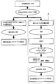
- FIG. 2 shows a simplified process flow of the method for producing a carbon fiber aggregate and carbon fiber reinforced plastic according to the present invention.
- FIG. 2 although the process of manufacturing a normal carbon fiber reinforced plastic (molded product) is also shown, the process flow portion A surrounded by a broken line relates to the present invention using the end material of the carbon fiber fabric.
- the process flow of the manufacturing method of a carbon fiber aggregate and a carbon fiber reinforced plastic is illustrated.
- the carbon fiber aggregate When the carbon fiber aggregate is a web or non-woven fabric, it is cut into 30 cm square, and when the carbon fiber aggregate is a sliver, it is cut into a length of 30 cm. In either case, it is heated in an electric furnace heated to 500 ° C. for 1 hour. The organic matter was burned off. 400 carbon fibers were randomly taken out from the remaining carbon fibers, the fiber length was measured, and the number average fiber length of the carbon fibers was determined using the value.
- the cut piece was disassembled into a bundle of carbon fibers using tweezers. If the carbon fiber fabric is difficult to decompose by sealing or stitching, it is heated in an electric furnace heated to 500 ° C. for 1 hour to burn off the organic matter, and then the residue is bundled with carbon fiber using tweezers. Disassembled until 400 carbon fibers were randomly taken out from the obtained bundle of carbon fibers, the fiber length was measured, and the number average fiber length of the carbon fibers was determined using the value.
- Carbon fiber content in carbon fiber reinforced plastic About 2 g of a sample was cut out from a molded product of carbon fiber reinforced plastic, and its mass was measured. Thereafter, the sample was heated in an electric furnace heated to 500 ° C. for 1 hour to burn off organic substances such as a matrix resin. After cooling to room temperature, the mass of the remaining carbon fiber was measured. The ratio of the mass of the carbon fiber to the mass of the sample before the organic substance such as the matrix resin was burned off was measured to obtain the carbon fiber content.
- Example 1 A flat woven fabric (“CO6343”, manufactured by Toray Industries, Inc.) made of carbon fiber (“T300”, manufactured by Toray Industries, Inc., density 1.76 g / cm 3 , diameter 7 ⁇ m, number of filaments 3000) is 5 cm square. After cutting into a cut piece, it was put into a cotton opening machine to decompose the woven fabric to obtain a carbon fiber bundle and a mixture of the opened carbon fibers. The number average fiber length of the carbon fibers in the cut piece was 48 mm. This mixture was put into a cotton opening machine again to obtain cotton-like carbon fibers having almost no carbon fiber bundles.
- This cotton-like carbon fiber and nylon 6 discontinuous fiber (single fiber fineness 1.7 dtex, cut length 51 mm, number of crimps 12/25 mm, crimp rate 15%) were mixed at a mass ratio of 50:50. . This mixture was again put into a cotton opening machine to obtain a mixed raw cotton made of carbon fiber and nylon 6 fiber.
- the mixed raw cotton was put into a carding apparatus having a structure as shown in FIG. 1 having a cylinder roll having a diameter of 600 mm, and a sheet-like web composed of carbon fibers and nylon 6 fibers was formed.
- the web was made into a rope shape while narrowing the width of the web, and then pulled to obtain a sliver.
- the rotation speed of the cylinder roll at this time was 350 rpm, and the speed of the doffer was 15 m / min.
- the number average fiber length of the carbon fibers was 31 mm.
- the carbon fiber was not dropped off or wound around the roll of the carding apparatus.
- the sliver was stretched while being twisted, and further continuously heated with an infrared heater to melt the nylon 6 fiber, then cooled and solidified, and cut into 10 mm to produce an injection molding material.
- This injection molding material and nylon 6 resin (“CM1001”, manufactured by Toray Industries, Inc.) are mixed so that the carbon fiber and nylon 6 (including nylon 6 fiber) are in a mass ratio of 20:80, and injection molding is performed.
- CM1001 manufactured by Toray Industries, Inc.
- CM1001 manufactured by Toray Industries, Inc.
- CM1001 manufactured by Toray Industries, Inc.
- the number average fiber length of carbon fibers in the obtained molded product was 0.9 mm.
- the bending strength of the obtained flat plate was measured, it was 350 MPa.
- Example 2 A sliver was obtained in the same manner as in Example 1 except that the same carbon fiber fabric as that used in Example 1 was cut into a 1 cm square. In the cut piece, the number average fiber length of the carbon fibers was 9 mm. Moreover, in the obtained sliver, the number average fiber length of the carbon fibers was 6 mm. In this carding step, the carbon fibers were observed to fall off, but no wrapping around the roll of the carding device occurred.
- a flat molded product of carbon fiber reinforced plastic was obtained in the same manner as in Example 1.
- the number average fiber length of carbon fibers in the obtained molded product was 0.6 mm. Moreover, it was 310 Mpa when the bending strength of the obtained flat plate was measured.
- Example 3 A sliver was obtained in the same manner as in Example 1 except that the same carbon fiber woven fabric as used in Example 1 was cut into a 20 cm square. In the cut piece, the number average fiber length of the carbon fibers was 18 cm. Moreover, in the obtained sliver, the number average fiber length of the carbon fibers was 31 mm. In this carding process, it was observed that the carbon fibers that had been cut and shortened in the carding process were dropped off, and a part of the carding device was wound around the roll.
- a flat molded product of carbon fiber reinforced plastic was obtained in the same manner as in Example 1.
- the number average fiber length of the carbon fibers in the obtained molded product was 0.7 mm.
- the bending strength of the obtained flat plate was measured, it was 330 MPa.
- Comparative Example 1 The same carbon fiber fabric used in Example 1 is cut into a cut piece, and the nylon 6 is mixed with a twin-screw mixer so that the mass ratio of carbon fiber to nylon 6 is 50:50. After kneading with a resin (“CM1001”, manufactured by Toray Industries, Inc.), it was extruded into a gut shape, cooled with water, and cut to produce pellets for injection molding. In addition, since the carbon fiber woven fabric after cutting could not be stably put into the biaxial kneader, the carbon fiber woven fabric was cut into 1 cm square and then put into the biaxial kneader. In the cut piece, the number average fiber length of the carbon fibers was 9 mm.
- CM1001 manufactured by Toray Industries, Inc.
- the obtained pellet for injection molding was injection molded by the same method as in Example 1 to obtain a flat molded product of carbon fiber reinforced plastic.
- the number average fiber length of carbon fibers in the obtained molded product was 0.1 mm. Moreover, it was 210 MPa when the bending strength of the obtained flat plate was measured.
- Example 4 A web was produced in the same manner as in Example 1 until a sheet-like web was produced.
- the number average fiber length of carbon fibers in the web was 36 mm.
- the basis weight variation (CV value) of carbon fibers in the carbon fiber aggregate web was 6%, and the thickness variation (CV value) was 7%.
- the limit shear deformation angle of the carbon fiber aggregate did not show a maximum value within the range up to 30 °, and exceeded 30 °.
- This web was laminated in the same direction, and a nylon 6 film was laminated so that the mass ratio of carbon fiber: nylon 6 (including nylon 6 fiber) was 30:70.
- the laminated web and nylon 6 film are sandwiched between polyimide films, and further sandwiched between aluminum plates. While pressing with a press machine at a pressure of 5 MPa, pressurizing at 250 ° C. for 3 minutes, then cooling to 40 ° C. and carbon fiber A flat plastic molded product of reinforced plastic was obtained.
- the number average fiber length of carbon fibers in the obtained molded product was 28 mm. Moreover, it was 410 MPa when the bending strength of the obtained flat plate was measured. Moreover, voids were not formed in CFRP, and the appearance was excellent.
- Example 5 A carbon fiber bundle composed of 12,000 carbon fiber single fibers (“T700S”, manufactured by Toray Industries, Inc., density 1.8, diameter 7 ⁇ m) is used as a reinforcing fiber, and polyester yarn (“Tetron”, Toray Industries, Inc., The number of filaments is 24 and the total fineness is 56 tex).
- the carbon fiber bundle is -45 ° / 90 ° / + 45 ° / 0 ° / + 45 ° / 90 ° / -45 ° with respect to the longitudinal direction of the multilayer substrate.
- a multi-axis stitch base material was prepared by arranging and laminating in this manner and integrating them with stitch yarns.
- the arrangement density of the carbon fiber yarn bundle is 3.75 pieces / cm and the basis weight of the carbon fiber bundle is 300 g / m 2 per two layers in each layer, and the arrangement interval of the stitch yarns is The stitch pitch was 5 mm.
- the proportion of stitch yarn present in the resulting multiaxial stitch fabric was 2% by weight.
- the end material after producing the preform for RTM using this multi-axis stitch base material was collected and placed on the table of an automatic cutting apparatus having an ultrasonic cutter moving in the XY direction on the table. Thereafter, the end material of the multi-axis stitch base material was cut while moving the ultrasonic cutter at an interval of 8 cm in the X direction and the Y direction to obtain a cut piece.
- the number average fiber length of the carbon fibers contained in the cut piece was 42 mm.
- the web was changed in the same manner as in Example 4 except that the cut pieces were changed to those obtained as described above, and carbon fibers and nylon 6 discontinuous fibers were mixed at a mass ratio of 80:20. Produced.
- the number average fiber length of carbon fibers was 40 mm.
- the basis weight variation of the carbon fibers in the carbon fiber aggregate web was 8% and the thickness variation was 8%.
- the limit shear deformation angle of the carbon fiber aggregate did not show a maximum value within the range up to 30 °, and exceeded 30 °.
- the obtained web was laminated in the same direction, and a film made of PPS (“Torcon”, Toray Industries, Inc.) was laminated so that the ratio of carbon fiber: PPS was 30:80.
- the laminated web and PPS film are sandwiched between polyimide films, and further sandwiched between aluminum plates. While pressing with a press machine at a pressure of 5 MPa, pressurize at 340 ° C for 3 minutes, then cool to 40 ° C to reinforce the carbon fiber.
- a plastic flat molded product was obtained.
- the number average fiber length of the carbon fibers in the obtained molded product was 21 mm. Moreover, when the bending strength of the obtained flat plate was measured, it was 340 MPa.
- Example 6 In the multi-axis stitch base material, the end material after preparing the preform for RTM was cut into a cut piece by using a Thomson blade die punched into a square of 8 cm square, and the same as in Example 5. I got the web. In this example, by using a Thomson blade die, cutting of the end material was more efficient than Example 5 and could be processed in a short time.
- the number average fiber length of the carbon fibers contained in the cut piece, the number average fiber length of the carbon fibers in the web, the basis weight variation of the carbon fibers in the web, the thickness variation, and the limit shear deformation angle are the same as in Example 5. there were.
- Example 7 As the same carbon fiber fabric as used in Example 1, carbon fiber plain fabric (“CO6343” manufactured by Toray Industries, Inc.) used in Example 1 and binder particles (low-melting quaternary copolymer nylon particles) The end material after producing the preform for RTM using the carbon fiber woven fabric with the binder coated with 5 g / m 2 and thermally welded was collected and cut with a Thomson blade mold, discontinuous nylon 6 A web was formed in the same manner as in Example 4 except that glass fiber (number average fiber length 10 cm) recycled instead of fiber was mixed at a mass ratio of carbon fiber 70: recycled glass fiber 30. The webs were laminated in the same direction and then needle punched to obtain a nonwoven fabric (100 g / m 2 ).
- CO6343 manufactured by Toray Industries, Inc.
- the number average fiber length of the carbon fibers was 32 mm. Moreover, in the obtained nonwoven fabric, the number average fiber length of the carbon fibers was 27 mm. In the carding, although the carbon fiber woven fabric with a binder that is difficult to unwind was used, the carding apparatus was not wound around the roll, and the process passability was good.
- the carbon fiber basis weight variation in the carbon fiber aggregate was 7%, and the thickness variation was 9%. Moreover, the limit shear deformation angle of the carbon fiber aggregate did not show a maximum value within the range up to 30 °, and exceeded 30 °.
- a flat molded product of carbon fiber reinforced plastic was obtained by resin transfer molding (RTM).
- RTM resin transfer molding
- the laminate is placed in a cavity of a flat plate-shaped mold composed of a male mold and a female mold, and the mold is clamped and sealed, and then the inside of the cavity is 0.08 to 0.00 mm from the vacuum suction port. Vacuum suction was performed so that the pressure was 1 MPa, and an epoxy resin as a matrix resin was injected under pressure from a resin injection port.
- the vacuum suction was stopped, the injection of the matrix resin was stopped, and the matrix resin was taken out after the lapse of 1 hour to obtain a flat molded product of carbon fiber reinforced plastic.
- the matrix resin was hardened by heating the mold to 110 ° C. before injection of the matrix resin and maintaining the same temperature after injection of the resin.
- TR-C32 manufactured by Toray Industries, Inc. was used as an epoxy resin.
- the number average fiber length of the carbon fibers in the obtained molded product was 27 mm, and the weight content Wf of the carbon fibers in the molded product was 55 wt%. Moreover, it was 635 MPa when the bending strength of the obtained flat plate was measured.
- RTM the fabric weight and thickness variation (CV value) of the non-woven fabric was low, so that the resin impregnation did not cause unstable flow, uniform resin flow was performed, voids were not formed, and the molded product had excellent appearance Was obtained.
- the present invention can be applied to the production of all carbon fiber aggregates and carbon fiber reinforced plastics for which it is desired to recycle the cut pieces of the carbon fiber base material.
Landscapes
- Engineering & Computer Science (AREA)
- Mechanical Engineering (AREA)
- Textile Engineering (AREA)
- Chemical & Material Sciences (AREA)
- Composite Materials (AREA)
- Inorganic Chemistry (AREA)
- Life Sciences & Earth Sciences (AREA)
- Forests & Forestry (AREA)
- Reinforced Plastic Materials (AREA)
- Nonwoven Fabrics (AREA)
Priority Applications (6)
| Application Number | Priority Date | Filing Date | Title |
|---|---|---|---|
| KR1020137003719A KR101931826B1 (ko) | 2010-12-24 | 2011-12-21 | 탄소 섬유 집합체의 제조 방법 및 탄소 섬유 강화 플라스틱의 제조 방법 |
| US13/878,449 US20130192434A1 (en) | 2010-12-24 | 2011-12-21 | Method for producing carbon fiber aggregate, and method for producing carbon fiber-reinforced plastic |
| CN201180046018.XA CN103119209B (zh) | 2010-12-24 | 2011-12-21 | 碳纤维聚集体的制造方法和碳纤维增强塑料的制造方法 |
| JP2012501481A JP5861941B2 (ja) | 2010-12-24 | 2011-12-21 | 炭素繊維集合体の製造方法および炭素繊維強化プラスチックの製造方法 |
| ES11850452T ES2716977T3 (es) | 2010-12-24 | 2011-12-21 | Método para producir un agregado de fibra de carbono y método para producir plástico reforzado con fibra de carbono |
| EP11850452.1A EP2642007B1 (en) | 2010-12-24 | 2011-12-21 | Method for producing carbon fiber aggregate, and method for producing carbon fiber-reinforced plastic |
Applications Claiming Priority (2)
| Application Number | Priority Date | Filing Date | Title |
|---|---|---|---|
| JP2010-287883 | 2010-12-24 | ||
| JP2010287883 | 2010-12-24 |
Publications (1)
| Publication Number | Publication Date |
|---|---|
| WO2012086682A1 true WO2012086682A1 (ja) | 2012-06-28 |
Family
ID=46313950
Family Applications (1)
| Application Number | Title | Priority Date | Filing Date |
|---|---|---|---|
| PCT/JP2011/079625 WO2012086682A1 (ja) | 2010-12-24 | 2011-12-21 | 炭素繊維集合体の製造方法および炭素繊維強化プラスチックの製造方法 |
Country Status (7)
| Country | Link |
|---|---|
| US (1) | US20130192434A1 (zh) |
| EP (1) | EP2642007B1 (zh) |
| JP (1) | JP5861941B2 (zh) |
| KR (1) | KR101931826B1 (zh) |
| CN (1) | CN103119209B (zh) |
| ES (1) | ES2716977T3 (zh) |
| WO (1) | WO2012086682A1 (zh) |
Cited By (26)
| Publication number | Priority date | Publication date | Assignee | Title |
|---|---|---|---|---|
| CN103963391A (zh) * | 2013-01-29 | 2014-08-06 | 上海杰事杰新材料(集团)股份有限公司 | 一种预浸带废料制备的夹心型复合材料及其制备方法 |
| JP2014196584A (ja) * | 2013-03-29 | 2014-10-16 | トヨタ自動車株式会社 | 不織布の製造方法および複合材料の製造方法 |
| JP2015081262A (ja) * | 2013-10-21 | 2015-04-27 | 学校法人同志社 | 再生炭素繊維強化プラスチック成形体およびその製造方法 |
| WO2015108021A1 (ja) * | 2014-01-17 | 2015-07-23 | 東レ株式会社 | スタンパブルシート |
| WO2015111536A1 (ja) * | 2014-01-22 | 2015-07-30 | 帝人株式会社 | 射出成形、押出成形、又は引抜成形用の成形材料、炭素繊維強化熱可塑性樹脂ペレット、成形体、射出成形体の製造方法、及び射出成形体 |
| CN105102705A (zh) * | 2013-03-25 | 2015-11-25 | 美术工艺株式会社 | 无纺布、片或薄膜、多层片、成型品和无纺布的制造方法 |
| US20160006038A1 (en) * | 2013-02-21 | 2016-01-07 | Audi Ag | Non-puncturing fuel cell gas diffusion layer |
| JP2016041800A (ja) * | 2014-08-18 | 2016-03-31 | エフテックス有限会社 | 炭素繊維強化ポリエステル樹脂およびその射出成型体の製造方法 |
| WO2016084824A1 (ja) * | 2014-11-26 | 2016-06-02 | 東レ株式会社 | 炭素繊維マット、プリフォーム、シート材料および成形品 |
| JP2016523310A (ja) * | 2013-06-25 | 2016-08-08 | ヘクセル コーポレイション | 不連続繊維成形コンパウンドの製造方法 |
| JP2016151081A (ja) * | 2015-02-19 | 2016-08-22 | 国立研究開発法人宇宙航空研究開発機構 | 炭素繊維シート及びこれを用いた炭素繊維強化樹脂成形体 |
| WO2016143645A1 (ja) * | 2015-03-06 | 2016-09-15 | 国立大学法人 東京大学 | チョップドテープ繊維強化熱可塑性樹脂シート材及びその製造方法 |
| WO2016152563A1 (ja) * | 2015-03-24 | 2016-09-29 | 帝人株式会社 | 炭素繊維強化樹脂複合材料 |
| JP2017053065A (ja) * | 2015-09-10 | 2017-03-16 | シンワ株式会社 | Frp製造用シート状半製品の製造方法 |
| EP2687349B1 (de) | 2012-07-18 | 2017-07-05 | Bayerische Motoren Werke Aktiengesellschaft | Verfahren zur Herstellung von Leichtbauelementen aus kohlenstofffaserverstärktem, thermoplastischem Kunststoff |
| JP2017160559A (ja) * | 2016-03-09 | 2017-09-14 | 住友ベークライト株式会社 | 抄造体の製造方法および成形体の製造方法 |
| RU2631037C1 (ru) * | 2016-06-14 | 2017-09-15 | Российская Федерация, от имени которой выступает Министерство промышленности и торговли Российской Федерации (Минпромторг России) | Устройство для мерной резки углеродного волокна |
| WO2018117743A1 (ko) * | 2016-12-23 | 2018-06-28 | 주식회사 하도에프앤씨 | 차량용 엔진룸 제조방법 |
| JP2018123438A (ja) * | 2017-01-30 | 2018-08-09 | 国立大学法人岐阜大学 | 炭素繊維ストランドおよびそれを用いた炭素繊維強化複合材料成形体の製造方法 |
| JP2019504128A (ja) * | 2015-11-12 | 2019-02-14 | サイテック インダストリーズ インコーポレイテッド | 複合材料の中間層としてのハイブリッドベール |
| WO2020040287A1 (ja) * | 2018-08-24 | 2020-02-27 | 阿波製紙株式会社 | 炭素繊維シート材、プリプレグ、成形体、炭素繊維シート材の製造方法、プリプレグの製造方法および成形体の製造方法 |
| WO2020040289A1 (ja) * | 2018-08-24 | 2020-02-27 | 阿波製紙株式会社 | 炭素繊維シート材、プリプレグ、成形体、炭素繊維シート材の製造方法、プリプレグの製造方法および成形体の製造方法 |
| JP2020100156A (ja) * | 2016-09-14 | 2020-07-02 | 三菱ケミカル株式会社 | 積層基材およびその製造方法並びに炭素繊維強化樹脂基材 |
| JP2021095646A (ja) * | 2019-12-13 | 2021-06-24 | 三菱製紙株式会社 | 炭素短繊維不織布及び炭素繊維強化プラスチック |
| JPWO2022249680A1 (zh) * | 2021-05-28 | 2022-12-01 | ||
| WO2022265099A1 (ja) * | 2021-06-18 | 2022-12-22 | 三菱ケミカル株式会社 | 自己組織化炭素繊維束及びその製造方法と、プリプレグ及びその製造方法 |
Families Citing this family (34)
| Publication number | Priority date | Publication date | Assignee | Title |
|---|---|---|---|---|
| DE102010008370A1 (de) * | 2010-02-17 | 2011-08-18 | Thüringisches Institut für Textil- und Kunststoff-Forschung e.V., 07407 | Verfahren zur Herstellung eines plattenförmigen Halbzeugs aus Faserverbundwerkstoff |
| CA2802301C (en) * | 2010-11-03 | 2016-04-26 | Birgit Reiter | Pile layer with curved bundles |
| DE102012025181A1 (de) * | 2012-12-26 | 2014-06-26 | Hubert Hergeth | Verfahren und Vorrichtung zum Trennen von Nähfäden und Karbonfasern |
| DE102013226921A1 (de) * | 2013-12-20 | 2015-06-25 | Sgl Automotive Carbon Fibers Gmbh & Co. Kg | Vliesstoff aus Carbonfasern und thermoplastischen Fasern |
| KR101975886B1 (ko) * | 2014-06-24 | 2019-05-07 | 코오롱인더스트리 주식회사 | 활성탄소섬유 원단용 필라멘트 웹 타입 전구체 원단 및 그의 제조방법 |
| CN104139530A (zh) * | 2014-06-25 | 2014-11-12 | 福建海源新材料科技有限公司 | 一种碳纤维增强热塑性聚酰亚胺模压成型方法 |
| CN106687267B (zh) * | 2014-09-17 | 2020-02-28 | 东丽株式会社 | 纤维增强树脂成型材料及其制造方法 |
| DE102014013867A1 (de) * | 2014-09-24 | 2016-03-24 | Carl Freudenberg Kg | Verwendung eines Carbonfaservliesstoffs als Isoliermaterial |
| EP3213912B1 (en) * | 2014-09-29 | 2022-01-19 | Sekisui Chemical Co., Ltd. | Carbon coated heat conducting material |
| DE102015002106A1 (de) | 2015-02-23 | 2016-08-25 | Basf Se | Prozessanordnung sowie Verfahren zur Herstellung eines faserverstärkten Kunststoffbauteils |
| EP3279243B1 (en) * | 2015-03-30 | 2019-11-06 | Toray Industries, Inc. | Fiber-reinforced resin molding material and method for producing same |
| CN104875790A (zh) * | 2015-05-26 | 2015-09-02 | 北京汽车股份有限公司 | 一种车顶盖及车顶盖的加工方法 |
| KR101797668B1 (ko) * | 2015-05-29 | 2017-12-13 | 한국생산기술연구원 | Cam 프로그램을 이용한 탄소 섬유 강화 플라스틱 가공 방법 |
| US20170136713A1 (en) * | 2015-11-13 | 2017-05-18 | James C. Holmes, IV | Composite materials and related methods for manufacturing composite materials |
| KR102107647B1 (ko) * | 2016-01-12 | 2020-05-07 | (주)엘지하우시스 | 리얼카본 제품 및 이의 제조방법 |
| WO2017175809A1 (ja) * | 2016-04-07 | 2017-10-12 | 三菱重工業株式会社 | 複合材の製造方法 |
| KR101993960B1 (ko) | 2016-10-31 | 2019-06-27 | 롯데첨단소재(주) | 탄소 섬유 강화 플라스틱용 직조물 및 이로부터 형성된 성형품 |
| KR102055974B1 (ko) | 2016-12-27 | 2019-12-13 | 롯데첨단소재(주) | 복합재 및 그 제조방법 |
| CN107498892A (zh) * | 2017-07-21 | 2017-12-22 | 安徽冠廷科技有限公司 | 一种空调室内机碳纤维外壳面板及其生产工艺 |
| CN108858940A (zh) * | 2018-03-19 | 2018-11-23 | 连云港神鹰复合材料科技有限公司 | 一种碳纤维锻造料轻量化法兰的制备方法 |
| WO2019208586A2 (ja) * | 2018-04-25 | 2019-10-31 | 旭化成株式会社 | 連続繊維強化樹脂成形体、及びその製造方法 |
| CN108640699B (zh) * | 2018-04-28 | 2020-10-27 | 中国人民解放军国防科技大学 | 一种碳纤维增强树脂基复合材料回收制备碳/碳预成型体的方法 |
| US11359309B2 (en) | 2018-12-21 | 2022-06-14 | Target Brands, Inc. | Ring spun yarn and method |
| IT201900001681A1 (it) * | 2019-02-06 | 2020-08-06 | Vincenzo Tagliaferri | Nuovo materiale composito per l’alleggerimento di varie strutture. |
| TWI710686B (zh) * | 2019-04-08 | 2020-11-21 | 科展材料科技股份有限公司 | 高分子複合材料擴纖織物與其製備方法 |
| KR102152204B1 (ko) * | 2019-05-20 | 2020-09-07 | 주식회사 코프라 | 섬유강화복합소재의 인서트 오버몰딩을 포함하는 자동차용 현가장치 제조방법 및 이를 통해 제조된 자동차용 현가장치 |
| JP7005557B2 (ja) * | 2019-06-06 | 2022-01-21 | 双葉電子工業株式会社 | 炭素繊維強化プラスチック板および炭素繊維強化プラスチック板の製造方法 |
| EP3812120A1 (en) * | 2019-10-24 | 2021-04-28 | Arrival Limited | Recycling of composite materials |
| AU2020383077A1 (en) * | 2019-11-11 | 2022-06-09 | Toray Industries, Inc. | Carbon fiber tape material, and reinforced fiber laminate and molded article using same |
| CN113752588B (zh) * | 2020-06-03 | 2022-07-01 | 上海飞机制造有限公司 | 一种飞机隔框的制造方法 |
| AU2021471596A1 (en) | 2021-10-29 | 2024-03-28 | Vartega Inc. | Fiber-containing particles with dual-tapered shape |
| EP4223488A1 (en) * | 2022-02-08 | 2023-08-09 | Universität Hamburg | Fiber-reinforced composite material containing photodegraded polyolefin as bonding agent |
| CN114801406B (zh) * | 2022-03-30 | 2024-03-12 | 亨弗劳恩(江苏)复合材料研发有限公司 | 一种制备回收碳纤维smc材料的系统及方法 |
| KR102636199B1 (ko) | 2023-11-30 | 2024-02-13 | 문정우 | 재생탄소섬유 부직포 제조시스템에 특화된 카드기 |
Citations (14)
| Publication number | Priority date | Publication date | Assignee | Title |
|---|---|---|---|---|
| JPH06288084A (ja) | 1993-04-02 | 1994-10-11 | Junichi Ishida | 複合建材用板材 |
| JPH06285889A (ja) * | 1993-04-05 | 1994-10-11 | Kusuo Sato | パウダ状の熱可塑性樹脂を使用した繊維強化プラスチックの連続プレス成形方法及びその装置 |
| JPH08337960A (ja) | 1995-06-13 | 1996-12-24 | Toray Ind Inc | 補強用織物の製造方法 |
| JP2001164441A (ja) | 1999-09-29 | 2001-06-19 | Fukui Prefecture | 開繊糸織物 |
| JP2003268669A (ja) | 2002-03-11 | 2003-09-25 | Toray Ind Inc | 補強繊維織物の製造方法および製造装置 |
| JP2004137425A (ja) * | 2002-10-21 | 2004-05-13 | Dainippon Ink & Chem Inc | エポキシ樹脂組成物およびその成形硬化物 |
| JP2005105491A (ja) | 2003-10-01 | 2005-04-21 | Du Pont Toray Co Ltd | 滑り難いリサイクル高機能紡績糸および高機能繊維製品 |
| JP2006218793A (ja) | 2005-02-14 | 2006-08-24 | Toray Ind Inc | 炭素繊維強化熱可塑性樹脂成形品のリサイクル方法 |
| JP2007162185A (ja) | 2005-12-16 | 2007-06-28 | Toray Ind Inc | 基材の賦型性の評価方法およびfrpの製造方法 |
| JP2008081872A (ja) * | 2006-09-27 | 2008-04-10 | Takayasu Co Ltd | 炭素繊維不織布及びその製造方法 |
| JP2008132705A (ja) * | 2006-11-29 | 2008-06-12 | Toray Ind Inc | 炭素繊維積層体およびそれを用いた炭素繊維強化樹脂 |
| JP2009066885A (ja) | 2007-09-12 | 2009-04-02 | Namba Press Works Co Ltd | 裁断屑を用いた成形体およびその製造方法 |
| JP2009138143A (ja) | 2007-12-07 | 2009-06-25 | Toyota Motor Corp | 繊維強化プラスチックのリサイクル方法 |
| JP3152748U (ja) * | 2009-05-31 | 2009-08-13 | エアテクス株式会社 | カーボン不織布 |
Family Cites Families (15)
| Publication number | Priority date | Publication date | Assignee | Title |
|---|---|---|---|---|
| AU517708B2 (en) * | 1978-01-12 | 1981-08-20 | Dunlop Limited | Carbon composite brake disc manufacture |
| FR2626294B1 (fr) * | 1988-01-26 | 1990-07-13 | Carbone Ind | Procede de fabrication d'une structure fibreuse tridimensionnelle en vue de la realisation ulterieure d'une piece en un materiau composite et machine pour sa mise en oeuvre |
| CA2077130C (en) * | 1991-09-04 | 2003-04-29 | Edward Lee Morris | Carbon fiber reinforced carbon/carbon composite and method of its manufacture |
| JP3152748B2 (ja) * | 1992-07-07 | 2001-04-03 | 富士通株式会社 | トナー像記録装置の定着装置 |
| JP3505754B2 (ja) * | 1993-12-02 | 2004-03-15 | 東レ株式会社 | プリプレグおよびその製造方法 |
| US5871844A (en) * | 1997-04-02 | 1999-02-16 | Fiberite, Inc. | Carbon--carbon parts having filamentized composite fiber substrates and methods of producing the same |
| JP2001288288A (ja) * | 2000-04-07 | 2001-10-16 | Satoshi Ukita | カーボンシート |
| DE10103213A1 (de) * | 2001-01-25 | 2002-08-14 | Wacker Polymer Systems Gmbh | Verfahren zur Herstellung von wiederverwertbaren Formkörpern |
| JP4297138B2 (ja) * | 2005-07-05 | 2009-07-15 | 三菱樹脂株式会社 | 炭素繊維強化SiC系複合材及び摺動材 |
| JP5176564B2 (ja) * | 2007-02-02 | 2013-04-03 | 東レ株式会社 | Cfrp製パネル構造体 |
| US20090309260A1 (en) * | 2008-06-12 | 2009-12-17 | Kenneth Herbert Keuchel | Method of delivering a thermoplastic and/or crosslinking resin to a composite laminate structure |
| WO2010125545A2 (en) * | 2009-04-30 | 2010-11-04 | Kimberly-Clark Worldwide, Inc. | Nonwoven composite including post-consumer recycled material |
| DE102009023529A1 (de) * | 2009-05-30 | 2010-12-02 | Bayerische Motoren Werke Aktiengesellschaft | Recyclingverfahren |
| DE102010008370A1 (de) | 2010-02-17 | 2011-08-18 | Thüringisches Institut für Textil- und Kunststoff-Forschung e.V., 07407 | Verfahren zur Herstellung eines plattenförmigen Halbzeugs aus Faserverbundwerkstoff |
| JP5897593B2 (ja) * | 2010-12-01 | 2016-03-30 | サイテク・テクノロジー・コーポレーシヨン | 複合品製造用樹脂溶解性ベールおよびそれの製造方法 |
-
2011
- 2011-12-21 KR KR1020137003719A patent/KR101931826B1/ko active IP Right Grant
- 2011-12-21 WO PCT/JP2011/079625 patent/WO2012086682A1/ja active Application Filing
- 2011-12-21 US US13/878,449 patent/US20130192434A1/en not_active Abandoned
- 2011-12-21 JP JP2012501481A patent/JP5861941B2/ja active Active
- 2011-12-21 EP EP11850452.1A patent/EP2642007B1/en not_active Not-in-force
- 2011-12-21 ES ES11850452T patent/ES2716977T3/es active Active
- 2011-12-21 CN CN201180046018.XA patent/CN103119209B/zh not_active Expired - Fee Related
Patent Citations (14)
| Publication number | Priority date | Publication date | Assignee | Title |
|---|---|---|---|---|
| JPH06288084A (ja) | 1993-04-02 | 1994-10-11 | Junichi Ishida | 複合建材用板材 |
| JPH06285889A (ja) * | 1993-04-05 | 1994-10-11 | Kusuo Sato | パウダ状の熱可塑性樹脂を使用した繊維強化プラスチックの連続プレス成形方法及びその装置 |
| JPH08337960A (ja) | 1995-06-13 | 1996-12-24 | Toray Ind Inc | 補強用織物の製造方法 |
| JP2001164441A (ja) | 1999-09-29 | 2001-06-19 | Fukui Prefecture | 開繊糸織物 |
| JP2003268669A (ja) | 2002-03-11 | 2003-09-25 | Toray Ind Inc | 補強繊維織物の製造方法および製造装置 |
| JP2004137425A (ja) * | 2002-10-21 | 2004-05-13 | Dainippon Ink & Chem Inc | エポキシ樹脂組成物およびその成形硬化物 |
| JP2005105491A (ja) | 2003-10-01 | 2005-04-21 | Du Pont Toray Co Ltd | 滑り難いリサイクル高機能紡績糸および高機能繊維製品 |
| JP2006218793A (ja) | 2005-02-14 | 2006-08-24 | Toray Ind Inc | 炭素繊維強化熱可塑性樹脂成形品のリサイクル方法 |
| JP2007162185A (ja) | 2005-12-16 | 2007-06-28 | Toray Ind Inc | 基材の賦型性の評価方法およびfrpの製造方法 |
| JP2008081872A (ja) * | 2006-09-27 | 2008-04-10 | Takayasu Co Ltd | 炭素繊維不織布及びその製造方法 |
| JP2008132705A (ja) * | 2006-11-29 | 2008-06-12 | Toray Ind Inc | 炭素繊維積層体およびそれを用いた炭素繊維強化樹脂 |
| JP2009066885A (ja) | 2007-09-12 | 2009-04-02 | Namba Press Works Co Ltd | 裁断屑を用いた成形体およびその製造方法 |
| JP2009138143A (ja) | 2007-12-07 | 2009-06-25 | Toyota Motor Corp | 繊維強化プラスチックのリサイクル方法 |
| JP3152748U (ja) * | 2009-05-31 | 2009-08-13 | エアテクス株式会社 | カーボン不織布 |
Non-Patent Citations (2)
| Title |
|---|
| "Ministry of Economy, Trade and Industry, regional new industry creation technology development assistant enterprise", EPOXY CFRP RECYCLE BY NORMAL PRESSURE DISSOLUTION METHOD, Retrieved from the Internet <URL:http://www.hitachi-chem.co.jp/Japanese/csr/files/frp_recycling_technology_2.pdf> |
| See also references of EP2642007A4 |
Cited By (43)
| Publication number | Priority date | Publication date | Assignee | Title |
|---|---|---|---|---|
| EP2687349B1 (de) | 2012-07-18 | 2017-07-05 | Bayerische Motoren Werke Aktiengesellschaft | Verfahren zur Herstellung von Leichtbauelementen aus kohlenstofffaserverstärktem, thermoplastischem Kunststoff |
| CN103963391A (zh) * | 2013-01-29 | 2014-08-06 | 上海杰事杰新材料(集团)股份有限公司 | 一种预浸带废料制备的夹心型复合材料及其制备方法 |
| US20160006038A1 (en) * | 2013-02-21 | 2016-01-07 | Audi Ag | Non-puncturing fuel cell gas diffusion layer |
| CN105102705A (zh) * | 2013-03-25 | 2015-11-25 | 美术工艺株式会社 | 无纺布、片或薄膜、多层片、成型品和无纺布的制造方法 |
| JP2014196584A (ja) * | 2013-03-29 | 2014-10-16 | トヨタ自動車株式会社 | 不織布の製造方法および複合材料の製造方法 |
| JP2016523310A (ja) * | 2013-06-25 | 2016-08-08 | ヘクセル コーポレイション | 不連続繊維成形コンパウンドの製造方法 |
| JP2015081262A (ja) * | 2013-10-21 | 2015-04-27 | 学校法人同志社 | 再生炭素繊維強化プラスチック成形体およびその製造方法 |
| WO2015108021A1 (ja) * | 2014-01-17 | 2015-07-23 | 東レ株式会社 | スタンパブルシート |
| JP5843048B1 (ja) * | 2014-01-17 | 2016-01-13 | 東レ株式会社 | スタンパブルシート |
| WO2015111536A1 (ja) * | 2014-01-22 | 2015-07-30 | 帝人株式会社 | 射出成形、押出成形、又は引抜成形用の成形材料、炭素繊維強化熱可塑性樹脂ペレット、成形体、射出成形体の製造方法、及び射出成形体 |
| US9783646B2 (en) | 2014-01-22 | 2017-10-10 | Teijin Limited | Molding material for injection molding, extrusion molding or pultrusion molding, carbon-fiber-reinforced thermoplastic resin pellet, molding product, method for producing injection molded product, and injection molded product |
| JP2016041800A (ja) * | 2014-08-18 | 2016-03-31 | エフテックス有限会社 | 炭素繊維強化ポリエステル樹脂およびその射出成型体の製造方法 |
| WO2016084824A1 (ja) * | 2014-11-26 | 2016-06-02 | 東レ株式会社 | 炭素繊維マット、プリフォーム、シート材料および成形品 |
| JP2016151081A (ja) * | 2015-02-19 | 2016-08-22 | 国立研究開発法人宇宙航空研究開発機構 | 炭素繊維シート及びこれを用いた炭素繊維強化樹脂成形体 |
| JPWO2016143645A1 (ja) * | 2015-03-06 | 2017-12-21 | 国立大学法人 東京大学 | チョップドテープ繊維強化熱可塑性樹脂シート材及びその製造方法 |
| WO2016143645A1 (ja) * | 2015-03-06 | 2016-09-15 | 国立大学法人 東京大学 | チョップドテープ繊維強化熱可塑性樹脂シート材及びその製造方法 |
| WO2016152563A1 (ja) * | 2015-03-24 | 2016-09-29 | 帝人株式会社 | 炭素繊維強化樹脂複合材料 |
| JPWO2016152563A1 (ja) * | 2015-03-24 | 2017-04-27 | 帝人株式会社 | 炭素繊維強化樹脂複合材料 |
| US10406762B2 (en) | 2015-03-24 | 2019-09-10 | Teijin Limited | Carbon-fiber-reinforced resin composite material |
| JP2017053065A (ja) * | 2015-09-10 | 2017-03-16 | シンワ株式会社 | Frp製造用シート状半製品の製造方法 |
| JP2019504128A (ja) * | 2015-11-12 | 2019-02-14 | サイテック インダストリーズ インコーポレイテッド | 複合材料の中間層としてのハイブリッドベール |
| US11745439B2 (en) | 2015-11-12 | 2023-09-05 | Cytec Industries Inc. | Hybrid veil as interlayer in composite materials |
| JP2017160559A (ja) * | 2016-03-09 | 2017-09-14 | 住友ベークライト株式会社 | 抄造体の製造方法および成形体の製造方法 |
| RU2631037C1 (ru) * | 2016-06-14 | 2017-09-15 | Российская Федерация, от имени которой выступает Министерство промышленности и торговли Российской Федерации (Минпромторг России) | Устройство для мерной резки углеродного волокна |
| JP2020100156A (ja) * | 2016-09-14 | 2020-07-02 | 三菱ケミカル株式会社 | 積層基材およびその製造方法並びに炭素繊維強化樹脂基材 |
| KR20180074356A (ko) * | 2016-12-23 | 2018-07-03 | 주식회사 하도에프앤씨 | 차량용 엔진룸 제조방법 |
| WO2018117743A1 (ko) * | 2016-12-23 | 2018-06-28 | 주식회사 하도에프앤씨 | 차량용 엔진룸 제조방법 |
| US11414028B2 (en) | 2016-12-23 | 2022-08-16 | Hado Fnc Co., Ltd. | Vehicular engine room manufacturing method |
| KR101895541B1 (ko) | 2016-12-23 | 2018-09-11 | 주식회사 하도에프앤씨 | 차량용 엔진룸 제조방법 |
| JP2018123438A (ja) * | 2017-01-30 | 2018-08-09 | 国立大学法人岐阜大学 | 炭素繊維ストランドおよびそれを用いた炭素繊維強化複合材料成形体の製造方法 |
| WO2020040287A1 (ja) * | 2018-08-24 | 2020-02-27 | 阿波製紙株式会社 | 炭素繊維シート材、プリプレグ、成形体、炭素繊維シート材の製造方法、プリプレグの製造方法および成形体の製造方法 |
| WO2020040289A1 (ja) * | 2018-08-24 | 2020-02-27 | 阿波製紙株式会社 | 炭素繊維シート材、プリプレグ、成形体、炭素繊維シート材の製造方法、プリプレグの製造方法および成形体の製造方法 |
| JPWO2020040289A1 (ja) * | 2018-08-24 | 2021-08-10 | 阿波製紙株式会社 | 炭素繊維シート材、プリプレグ、成形体、炭素繊維シート材の製造方法、プリプレグの製造方法および成形体の製造方法 |
| JPWO2020040287A1 (ja) * | 2018-08-24 | 2021-08-26 | 阿波製紙株式会社 | 炭素繊維シート材、プリプレグ、成形体、炭素繊維シート材の製造方法、プリプレグの製造方法および成形体の製造方法 |
| JP7425731B2 (ja) | 2018-08-24 | 2024-01-31 | 阿波製紙株式会社 | 炭素繊維シート材、プリプレグ、成形体、炭素繊維シート材の製造方法、プリプレグの製造方法および成形体の製造方法 |
| JP7425732B2 (ja) | 2018-08-24 | 2024-01-31 | 阿波製紙株式会社 | 炭素繊維シート材、プリプレグ、成形体、炭素繊維シート材の製造方法、プリプレグの製造方法および成形体の製造方法 |
| JP2021095646A (ja) * | 2019-12-13 | 2021-06-24 | 三菱製紙株式会社 | 炭素短繊維不織布及び炭素繊維強化プラスチック |
| JPWO2022249680A1 (zh) * | 2021-05-28 | 2022-12-01 | ||
| WO2022249680A1 (ja) * | 2021-05-28 | 2022-12-01 | 富士加飾株式会社 | リサイクル炭素繊維収束体組成物、およびその製造方法 |
| JP2023055701A (ja) * | 2021-06-18 | 2023-04-18 | 三菱ケミカル株式会社 | 自己組織化炭素繊維束及びその製造方法と、プリプレグ及びその製造方法 |
| JP7268806B2 (ja) | 2021-06-18 | 2023-05-08 | 三菱ケミカル株式会社 | 自己組織化炭素繊維束及びその製造方法と、プリプレグ及びその製造方法 |
| JP7231126B1 (ja) * | 2021-06-18 | 2023-03-01 | 三菱ケミカル株式会社 | 自己組織化炭素繊維束及びその製造方法と、プリプレグ及びその製造方法 |
| WO2022265099A1 (ja) * | 2021-06-18 | 2022-12-22 | 三菱ケミカル株式会社 | 自己組織化炭素繊維束及びその製造方法と、プリプレグ及びその製造方法 |
Also Published As
| Publication number | Publication date |
|---|---|
| KR20130139857A (ko) | 2013-12-23 |
| EP2642007B1 (en) | 2018-10-24 |
| US20130192434A1 (en) | 2013-08-01 |
| JPWO2012086682A1 (ja) | 2014-05-22 |
| CN103119209A (zh) | 2013-05-22 |
| EP2642007A1 (en) | 2013-09-25 |
| JP5861941B2 (ja) | 2016-02-16 |
| CN103119209B (zh) | 2015-08-12 |
| KR101931826B1 (ko) | 2018-12-21 |
| ES2716977T3 (es) | 2019-06-18 |
| EP2642007A4 (en) | 2014-05-21 |
Similar Documents
| Publication | Publication Date | Title |
|---|---|---|
| JP5861941B2 (ja) | 炭素繊維集合体の製造方法および炭素繊維強化プラスチックの製造方法 | |
| JP5920227B2 (ja) | 炭素繊維強化プラスチックの製造方法 | |
| JP5687812B1 (ja) | ランダムマット、繊維強化複合材料成形体、および炭素繊維マット | |
| JP5919755B2 (ja) | 繊維材料の製造方法 | |
| JP2013519000A (ja) | 炭素繊維糸およびその製造方法 | |
| JP2013519762A (ja) | 繊維複合材料からのペレットの製造法 | |
| JP2013519546A (ja) | 繊維複合材料からのシート状の半製品の製造法 | |
| JP5749343B2 (ja) | アンダーカット部を有する複合成形体の製造方法 | |
| CN108215399A (zh) | 用于复合结构的纤维改性夹层以及制造方法 | |
| JP6083239B2 (ja) | 繊維強化プラスチックおよびその製造方法 | |
| JP5812439B2 (ja) | 繊維強化熱可塑性樹脂の積層成形品 | |
| CN110168148B (zh) | 纳米颗粒增强聚合物纳米纤维及用于产生它的连续过程 | |
| JP4341419B2 (ja) | プリフォームの製造方法および複合材料の製造方法 | |
| WO2013175183A2 (en) | Process | |
| US9981447B2 (en) | Fiber-reinforced resin joined body having caulked part and manufacturing method thereof | |
| JP2013049750A (ja) | 有機繊維ランダムマット及びこれを用いた繊維複合材料 | |
| JP7216383B1 (ja) | 炭素繊維不織布シート、その製造方法及びこれを用いた炭素繊維強化樹脂成形体 | |
| JP6722471B2 (ja) | 炭素繊維シート、複合材料及び複合材料の製造方法 | |
| JP2016107548A (ja) | スタンパブル基材及びその製造方法、並びにスタンピング成形品 | |
| TW202124135A (zh) | 碳纖維帶材料、以及使用其之強化纖維積層體及成形體 | |
| JP2016183248A (ja) | シート材料、一体化成形品および一体化成形品の製造方法 |
Legal Events
| Date | Code | Title | Description |
|---|---|---|---|
| WWE | Wipo information: entry into national phase |
Ref document number: 201180046018.X Country of ref document: CN |
|
| WWE | Wipo information: entry into national phase |
Ref document number: 2012501481 Country of ref document: JP |
|
| 121 | Ep: the epo has been informed by wipo that ep was designated in this application |
Ref document number: 11850452 Country of ref document: EP Kind code of ref document: A1 |
|
| ENP | Entry into the national phase |
Ref document number: 20137003719 Country of ref document: KR Kind code of ref document: A |
|
| WWE | Wipo information: entry into national phase |
Ref document number: 2011850452 Country of ref document: EP |
|
| WWE | Wipo information: entry into national phase |
Ref document number: 13878449 Country of ref document: US |
|
| NENP | Non-entry into the national phase |
Ref country code: DE |