WO2012029239A1 - Pneumatique - Google Patents
Pneumatique Download PDFInfo
- Publication number
- WO2012029239A1 WO2012029239A1 PCT/JP2011/004575 JP2011004575W WO2012029239A1 WO 2012029239 A1 WO2012029239 A1 WO 2012029239A1 JP 2011004575 W JP2011004575 W JP 2011004575W WO 2012029239 A1 WO2012029239 A1 WO 2012029239A1
- Authority
- WO
- WIPO (PCT)
- Prior art keywords
- tire
- decorative band
- mark
- radial direction
- ridge
- Prior art date
Links
Images

Classifications
-
- B—PERFORMING OPERATIONS; TRANSPORTING
- B60—VEHICLES IN GENERAL
- B60C—VEHICLE TYRES; TYRE INFLATION; TYRE CHANGING; CONNECTING VALVES TO INFLATABLE ELASTIC BODIES IN GENERAL; DEVICES OR ARRANGEMENTS RELATED TO TYRES
- B60C13/00—Tyre sidewalls; Protecting, decorating, marking, or the like, thereof
- B60C13/001—Decorating, marking or the like
Definitions
- the present invention relates to a pneumatic tire in which an annular decorative band formed by a large number of ridges and a mark made of predetermined characters, symbols or figures are arranged on the outer surface of a tire side portion. It is.
- the tire is formed of an annular decorative band extending in the tire circumferential direction, a company name, a product name, a size display, a character such as a manufacturing country, a predetermined symbol or a figure on the outer surface of the tire side portion.
- One or more marks are arranged to enhance the decorativeness of the tire itself, and by making the marks stand out, the tire can be distinguished from other tires. Since the space in which such decorative bands and marks can be arranged is limited, various devices have been conventionally used to arrange the decorative bands and marks so as to stand out even in narrow spaces. For example, as described in Patent Document 1, a mark is arranged within the width of a decorative band formed by alternately arranging two regions having different ridge densities in the tire circumferential direction. Some of the marks within the ornamental band width are made to stand out by the subtle changes in the reflected light due to.
- the decorative band as described above is formed by processing a required ridge into a vulcanization mold, but in order not to impair the visibility of the mark, the mark should be larger than a predetermined size.
- the width of the decorative band has increased, leading to an increase in the processing cost of the vulcanization mold.
- a general tire has a folded end of a carcass that is folded from the inner side to the outer side in the tire width direction around the bead core at the tire side portion. Irregularities on the inner and outer sides in the radial direction are likely to occur, and there is a problem that the irregularities impair the appearance of the tire.
- the rubber gauge on the tire side portion becomes thinner and the unevenness tends to be more noticeable, it is strongly desired to improve the tire that can cope with such a problem. It was.
- An object of the present invention is to provide an air provided with an annular decorative band formed of a plurality of ridges and one or more marks made of predetermined characters, symbols or figures on the outer surface of the tire side portion.
- An object of the present invention is to provide a tire in which the visibility of a mark is kept high and the appearance of the tire is not impaired and the manufacturing cost of the vulcanization mold can be suppressed.
- the present invention provides a pneumatic tire provided with an annular decorative band formed of a plurality of ridges and one or more marks made of predetermined characters, symbols or figures on the outer surface of a tire side portion.
- the decorative band is disposed over the both sides of the inner side and the outer side in the tire radial direction from the position corresponding to the folded end of the carcass, and the width of the decorative band is disposed so as to overlap the decorative band.
- the air is made narrower than the maximum value in the tire radial direction length, and the mark is arranged so as to protrude from the position overlapping with the decorative band to either the outer side or the inner side in the tire radial direction. This is a tire.
- the inner end or the outer end in the tire radial direction in the overlapping region of the mark with the decorative band is disposed in the central width region of the decorative band.
- the width central region of the decorative band refers to a region extending about 95%, preferably about 80% of the width of the decorative band on the inner side and the outer side in the tire radial direction with the central width of the decorative band as the center.
- the mark is arranged so as to protrude outward in the tire radial direction.
- the mark is formed to protrude from the ridge of the decorative band to the outer surface side in an overlapping area with the decorative band of the mark.
- the mark is bordered by a raised ridge, and a ridge in the mark is provided in the surrounding area by the raised ridge.
- the ridge of the decorative band is inclined in the range of 30 ° to 60 ° with respect to the tire meridian.
- An annular decorative band and one or more marks are arranged on the outer surface of the tire side portion, and the decorative band extends from the position corresponding to the folded end of the carcass to both the inner side and the outer side in the tire radial direction. Since the width of the decorative band is narrower than the mark that has the maximum length in the tire radial direction among the marks placed on the decorative band, the width of the decorative band is sufficiently large. It is possible to make the irregularities appearing around the folded end of the carcass in the tire side portion inconspicuous without making the ridges of the decorative band high density and making the extending form complicated while narrowing.
- the processing cost of the vulcanization mold for providing the decorative band can be sufficiently suppressed, the weight of the tire can be reduced by reducing the ridge, and the appearance of the product tire can be further reduced. It can be effectively prevented.
- this mark can be placed across both the part where the decorative band is present and the part where it is not present. As a result, the difference between the mark and the background stands out, and the visibility can be sufficiently enhanced.
- the production cost of the vulcanization mold can be suppressed without impairing the appearance of the tire, and the visibility of the mark can be improved.
- the mark when the mark is placed so as to protrude outward in the tire radial direction, there is a margin in the tire circumferential length, and the size of the mark can be increased, so that the visibility can be further enhanced sufficiently. it can.
- the mark when the mark is formed so as to protrude from the ridge of the decorative band toward the outer surface of the tire in an overlapping area with the decorative band of the mark, the mark can be made more conspicuous. Therefore, according to this tire, the visibility of the mark can be further improved.
- the mark when the mark is framed with a raised ridge and the ridge in the mark is provided in the surrounding area of the raised ridge, the mark can be made more conspicuous. Therefore, according to this tire, even better visibility of the mark can be obtained.
- the tire side portion is not affected by the rigidity step in the tire radial direction at the folded end of the carcass.
- the unevenness appearing around the position corresponding to the folded end can be made inconspicuous.
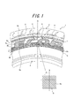
- FIG. 1 is a partial side view and a partially enlarged view of a tire showing an embodiment of a pneumatic tire according to the present invention.
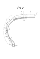
- FIG. 2 is a half sectional view of the tire shown in FIG. 1 in the meridian direction.
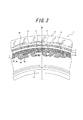
- FIG. 3 is a partial side view of a tire showing another embodiment of a pneumatic tire according to the present invention. It is a principal part enlarged view of FIG. 2 which shows the arrangement
- the product tire 1 includes a tread portion 2, a pair of sidewall portions 3 and a bead portion 4, a carcass 5 extending toroidally between the pair of bead portions 4, and comprising at least one ply cord layer, and the carcass 5.
- the belt 6 is disposed between the crown region 5a and the tread rubber 2a, and the side portion 5b of the carcass 5 is arranged around the bead core 4a disposed on the bead portion 4 from the inside in the tire width direction to the outside.
- the folded end 5 c is positioned on the tire side portion 7.
- the tire side portion 7 refers to a range from the outer edge in the tire width direction of the tread portion 2 to the rim fitting portion of the bead portion 4.
- the rubber gauge t (the rubber thickness from the ply cord to the outer surface of the tire side portion 7) of the tire side portion 7 at the folded end 5c shown in FIG. 1 is about 1.5 mm to 3.0 mm.
- an annular decorative band 8 is formed on the outer surface 7 a of the tire side portion 7 by a plurality of ridges 8 a arranged in the tire circumferential direction.
- the ridge 8a can be extended in a straight line parallel to the tire meridian M or inclined at a predetermined angle ⁇ , and can be curved with a predetermined curvature to extend in a curved line. It can also be.
- marks 9 made of predetermined characters, symbols or figures are arranged on the outer surface 7a. As shown in FIG. 1, the mark 9 is disposed so as to protrude outward in the tire radial direction from the position overlapping with the decorative band 8, or as illustrated in FIG. To do.
- the decorative band 8 is disposed over both the inner side and the outer side in the tire radial direction at the position corresponding to the turn-back end 5 c with reference to the position corresponding to the turn-back end 5 c of the carcass.
- the width w in the radial direction of the decorative band 8 shown in FIG. 1 is narrower than the longest radial direction length of the tire among the marks 9 arranged so as to overlap the decorative band 8. Yes.
- the unevenness appearing around the position corresponding to the folded end 5c of the outer surface 7a can be made inconspicuous with the decorative band 8 even if the rubber cage is made thin to some extent, and the width w of the decorative band 8 itself Can be minimized.
- the width w of the decorative band 8 can be about 4 to 20 mm.
- the mark 9 is arranged across both the portion where the decorative band 8 exists and the portion where the decorative band 8 does not exist. Since the background of the mark 9 is, the difference between the mark 9 and the background is more conspicuous, and the visibility can be sufficiently enhanced.
- the marks 9 are arranged so as to protrude outward in the tire radial direction from the decorative band 8 as shown in FIG. 1, even when a plurality of the marks 9 are arranged in the tire circumferential direction, the adjacent marks 9 are mutually connected. Since there is a margin in the interval between them and the size of the mark 9 can be increased, the visibility of the mark 9 can be further enhanced.
- the tire radial inner end 9 a or the tire radial outer end 9 b of the mark 9 overlaps the radially inner and outer boundary 8 b of the decorative band 8.
- the mark 9 has the tire radial inner end 9a shown in FIG. 1 or the tire radial outer end 9b shown in FIG. 3 aligned at a position corresponding to the turn-up end 5c of the carcass 5 in the tire side portion.
- the difference between the mark 9 and the background can be made more conspicuous.
- the raised ridge 9c is formed so as to protrude toward the outer surface of the tire from the ridge 9d in the mark, the raised ridge 9c effectively prevents damage to the ridge 9d in the mark. be able to.
- the outer surface 7 a is provided with a recess 8 c that is recessed toward the inner side in the tire width direction, and the ridge 8 a protrudes from the bottom of the recess 8 c and protrudes.
- the ridge 8a is effectively protected even if the periphery of the decorative band 8 is rubbed by a curb or the like during use of the tire.
- the angle ⁇ of the ridge 8a with respect to the tire meridian M is preferably inclined at 30 ° to 60 °.
- the existence of a rigid step is unavoidable.
- the angle ⁇ is too small, the extending direction of the ridge 8a is in the tire circumferential direction. Since the extending direction of the folded end 5c is close to the extending direction, there is a risk that cracks are likely to occur in the ridge 8a.
- the extending direction of the ridge 8a there is a concern that the effect of the ridge 8a that makes the unevenness appearing around the position corresponding to the turn-back end 5c of the tire side portion inconspicuous cannot be sufficiently exhibited because it becomes close to a right angle with respect to the extending direction of the end 5c.
- the unevenness caused by the presence of the folded end 5c can be more effectively made inconspicuous while maintaining sufficient strength of the tire.
- the tires 1 to 4 conforming to the present invention and the reference tire as a conventional example were prototyped, the visual check of the mark of each tire was performed, and the visibility of the mark was investigated.
- the results are shown in Table 1. Note that the visibility is obtained by indicating the survey results of each tire as an index using the survey results of the reference tire as a conventional example as a control, and the larger the number, the better the visibility.
- the conforming tire 1 is provided with a decorative band (the decorative band has a width of 16 mm) of 8 mm on each of the inner side and the outer side in the tire radial direction around the position corresponding to the folded end of the carcass in the tire side portion.
- the decorative band is formed by providing a ridge having an adjacent interval of 1.0 mm in a concave portion that is recessed 0.4 mm inward in the tire width direction from the outer surface of the tire side portion. It is formed so as to be flush with the concave portion (no ridge is provided in the mark).
- the conforming tire 2 is a tire equivalent to the conforming tire 1 except that the mark is arranged so that the radially inner end is located at the center of the decorative band.
- the conforming tire 3 is a tire equivalent to the conforming tire 2 except that the mark protrudes 0.4 mm outward from the outer surface of the tire side portion in the tire radial direction.
- the conforming tire 4 forms a raised ridge that borders the inside of the mark and borders the mark, and is adjacent to the surrounding area by the raised ridge within the mark having a distance of 0.8 mm.
- the tire is equivalent to the conforming tire 3 except that a ridge is provided.
- the reference tire is the same tire as the conforming tire 1 except that the width of the decorative band is 29 mm and the mark is disposed within the width of the decorative band.
- the width of the decorative band is made narrower than the maximum value in the tire radial direction of the mark, and the mark protrudes in the tire radial direction from the position overlapping the decorative band (applicable tires 1 to 4). ), It became clear that the visibility equal to or better than that of conventional tires can be secured.
Abstract
Priority Applications (4)
| Application Number | Priority Date | Filing Date | Title |
|---|---|---|---|
| EP11821264.6A EP2612771B1 (fr) | 2010-08-31 | 2011-08-12 | Pneumatique |
| JP2012531667A JPWO2012029239A1 (ja) | 2010-08-31 | 2011-08-12 | 空気入りタイヤ |
| CN201180049228.4A CN103167962B (zh) | 2010-08-31 | 2011-08-12 | 充气轮胎 |
| US13/819,571 US20130228261A1 (en) | 2010-08-31 | 2011-08-12 | Pneumatic tire |
Applications Claiming Priority (2)
| Application Number | Priority Date | Filing Date | Title |
|---|---|---|---|
| JP2010-193933 | 2010-08-31 | ||
| JP2010193933 | 2010-08-31 |
Publications (1)
| Publication Number | Publication Date |
|---|---|
| WO2012029239A1 true WO2012029239A1 (fr) | 2012-03-08 |
Family
ID=45772366
Family Applications (1)
| Application Number | Title | Priority Date | Filing Date |
|---|---|---|---|
| PCT/JP2011/004575 WO2012029239A1 (fr) | 2010-08-31 | 2011-08-12 | Pneumatique |
Country Status (5)
| Country | Link |
|---|---|
| US (1) | US20130228261A1 (fr) |
| EP (1) | EP2612771B1 (fr) |
| JP (1) | JPWO2012029239A1 (fr) |
| CN (1) | CN103167962B (fr) |
| WO (1) | WO2012029239A1 (fr) |
Cited By (4)
| Publication number | Priority date | Publication date | Assignee | Title |
|---|---|---|---|---|
| JP2014125108A (ja) * | 2012-12-26 | 2014-07-07 | Sumitomo Rubber Ind Ltd | 空気入りタイヤ |
| JP6465192B1 (ja) * | 2017-11-20 | 2019-02-06 | 横浜ゴム株式会社 | 空気入りタイヤ |
| WO2019240053A1 (fr) * | 2018-06-15 | 2019-12-19 | 株式会社ブリヂストン | Pneumatique |
| JP2021024439A (ja) * | 2019-08-05 | 2021-02-22 | 横浜ゴム株式会社 | 空気入りタイヤ |
Families Citing this family (3)
| Publication number | Priority date | Publication date | Assignee | Title |
|---|---|---|---|---|
| FR3014365B1 (fr) * | 2013-12-11 | 2017-01-13 | Michelin & Cie | Pneumatique comportant un element graphique particulier |
| JP7099945B2 (ja) | 2018-12-18 | 2022-07-12 | 株式会社ブリヂストン | 空気入りタイヤ |
| DE112020002898T5 (de) * | 2019-08-05 | 2022-02-24 | The Yokohama Rubber Co., Ltd. | Luftreifen |
Citations (7)
| Publication number | Priority date | Publication date | Assignee | Title |
|---|---|---|---|---|
| JPS63106109A (ja) * | 1986-10-24 | 1988-05-11 | Bridgestone Corp | 空気入りタイヤ |
| JPH092028A (ja) | 1995-04-19 | 1997-01-07 | Bridgestone Corp | 多数のリッジによる装飾体を備えた空気入りタイヤ |
| JPH11321241A (ja) * | 1998-04-17 | 1999-11-24 | Bridgestone Corp | タイヤ側壁 |
| JP2003191719A (ja) * | 2001-12-27 | 2003-07-09 | Bridgestone Corp | 空気入りタイヤ |
| JP2007045328A (ja) * | 2005-08-10 | 2007-02-22 | Bridgestone Corp | 空気入りタイヤ |
| JP2010064656A (ja) * | 2008-09-11 | 2010-03-25 | Bridgestone Corp | 空気入りタイヤ |
| JP2010137604A (ja) * | 2008-12-09 | 2010-06-24 | Toyo Tire & Rubber Co Ltd | 空気入りタイヤ |
Family Cites Families (13)
| Publication number | Priority date | Publication date | Assignee | Title |
|---|---|---|---|---|
| JPH066967Y2 (ja) * | 1984-04-03 | 1994-02-23 | 住友ゴム工業株式会社 | タイヤ |
| JPS63106108A (ja) * | 1986-10-24 | 1988-05-11 | Bridgestone Corp | 空気入りタイヤ |
| JP3831072B2 (ja) * | 1997-07-08 | 2006-10-11 | 株式会社ブリヂストン | 多数のリッジよりなる装飾体を備えた空気入りタイヤ |
| JP4295455B2 (ja) * | 2001-10-19 | 2009-07-15 | 住友ゴム工業株式会社 | 空気入りタイヤ |
| EP1310384B1 (fr) * | 2001-11-08 | 2014-01-29 | Sumitomo Rubber Industries, Ltd. | Bandage pneumatique pour véhicule |
| JP2005125937A (ja) * | 2003-10-23 | 2005-05-19 | Bridgestone Corp | タイヤのサイドウォール装飾構造 |
| JP4036269B2 (ja) * | 2006-05-24 | 2008-01-23 | 横浜ゴム株式会社 | 空気入りタイヤ |
| US8256479B2 (en) * | 2006-05-24 | 2012-09-04 | The Yokohama Rubber Co., Ltd. | Pneumatic tire |
| JP2008189165A (ja) * | 2007-02-05 | 2008-08-21 | Yokohama Rubber Co Ltd:The | 空気入りタイヤ |
| JP5026840B2 (ja) * | 2007-04-03 | 2012-09-19 | 東洋ゴム工業株式会社 | 空気入りタイヤ |
| JP2009143488A (ja) * | 2007-12-17 | 2009-07-02 | Sumitomo Rubber Ind Ltd | 空気入りタイヤ |
| JP5160345B2 (ja) * | 2008-08-26 | 2013-03-13 | 東洋ゴム工業株式会社 | 空気入りタイヤ |
| JP2010179830A (ja) * | 2009-02-06 | 2010-08-19 | Bridgestone Corp | 空気入りタイヤ |
-
2011
- 2011-08-12 CN CN201180049228.4A patent/CN103167962B/zh not_active Expired - Fee Related
- 2011-08-12 US US13/819,571 patent/US20130228261A1/en not_active Abandoned
- 2011-08-12 WO PCT/JP2011/004575 patent/WO2012029239A1/fr active Application Filing
- 2011-08-12 JP JP2012531667A patent/JPWO2012029239A1/ja active Pending
- 2011-08-12 EP EP11821264.6A patent/EP2612771B1/fr not_active Not-in-force
Patent Citations (7)
| Publication number | Priority date | Publication date | Assignee | Title |
|---|---|---|---|---|
| JPS63106109A (ja) * | 1986-10-24 | 1988-05-11 | Bridgestone Corp | 空気入りタイヤ |
| JPH092028A (ja) | 1995-04-19 | 1997-01-07 | Bridgestone Corp | 多数のリッジによる装飾体を備えた空気入りタイヤ |
| JPH11321241A (ja) * | 1998-04-17 | 1999-11-24 | Bridgestone Corp | タイヤ側壁 |
| JP2003191719A (ja) * | 2001-12-27 | 2003-07-09 | Bridgestone Corp | 空気入りタイヤ |
| JP2007045328A (ja) * | 2005-08-10 | 2007-02-22 | Bridgestone Corp | 空気入りタイヤ |
| JP2010064656A (ja) * | 2008-09-11 | 2010-03-25 | Bridgestone Corp | 空気入りタイヤ |
| JP2010137604A (ja) * | 2008-12-09 | 2010-06-24 | Toyo Tire & Rubber Co Ltd | 空気入りタイヤ |
Non-Patent Citations (1)
| Title |
|---|
| See also references of EP2612771A4 * |
Cited By (10)
| Publication number | Priority date | Publication date | Assignee | Title |
|---|---|---|---|---|
| JP2014125108A (ja) * | 2012-12-26 | 2014-07-07 | Sumitomo Rubber Ind Ltd | 空気入りタイヤ |
| JP6465192B1 (ja) * | 2017-11-20 | 2019-02-06 | 横浜ゴム株式会社 | 空気入りタイヤ |
| WO2019098275A1 (fr) * | 2017-11-20 | 2019-05-23 | 横浜ゴム株式会社 | Bandage pneumatique |
| JP2019093771A (ja) * | 2017-11-20 | 2019-06-20 | 横浜ゴム株式会社 | 空気入りタイヤ |
| US11407258B2 (en) | 2017-11-20 | 2022-08-09 | The Yokohama Rubber Co., Ltd. | Pneumatic tire |
| WO2019240053A1 (fr) * | 2018-06-15 | 2019-12-19 | 株式会社ブリヂストン | Pneumatique |
| JP2019217818A (ja) * | 2018-06-15 | 2019-12-26 | 株式会社ブリヂストン | タイヤ |
| JP7006522B2 (ja) | 2018-06-15 | 2022-01-24 | 株式会社ブリヂストン | タイヤ |
| JP2021024439A (ja) * | 2019-08-05 | 2021-02-22 | 横浜ゴム株式会社 | 空気入りタイヤ |
| JP7207224B2 (ja) | 2019-08-05 | 2023-01-18 | 横浜ゴム株式会社 | 空気入りタイヤ |
Also Published As
| Publication number | Publication date |
|---|---|
| CN103167962A (zh) | 2013-06-19 |
| JPWO2012029239A1 (ja) | 2013-10-28 |
| EP2612771A1 (fr) | 2013-07-10 |
| CN103167962B (zh) | 2016-05-11 |
| EP2612771A4 (fr) | 2014-05-14 |
| EP2612771B1 (fr) | 2018-11-14 |
| US20130228261A1 (en) | 2013-09-05 |
Similar Documents
| Publication | Publication Date | Title |
|---|---|---|
| WO2012029239A1 (fr) | Pneumatique | |
| JP5793159B2 (ja) | 空気入りタイヤ | |
| JP6747932B2 (ja) | 空気入りタイヤ | |
| AU2011249396B2 (en) | Pneumatic tire | |
| JP5802236B2 (ja) | 空気入りタイヤ | |
| JP2012131283A (ja) | 空気入りタイヤ | |
| CN104057787A (zh) | 充气轮胎 | |
| JP6232844B2 (ja) | 空気入りタイヤ | |
| JP5232580B2 (ja) | 空気入りタイヤ | |
| JP2019196152A (ja) | 空気入りタイヤ | |
| JP5394679B2 (ja) | 空気入りタイヤ | |
| CN112423999B (zh) | 充气轮胎 | |
| JP7443764B2 (ja) | 空気入りタイヤ | |
| CN112384381B (zh) | 充气轮胎 | |
| JP2002211214A (ja) | 空気入りタイヤ | |
| JPS60128006A (ja) | サイド部形状を改良したラジアルタイヤ | |
| JP5241248B2 (ja) | 空気入りタイヤ | |
| JP2021091330A (ja) | 空気入りタイヤ | |
| JP2021104745A (ja) | 空気入りタイヤ | |
| USD989703S1 (en) | Tire sidewall | |
| JP2016097778A (ja) | 空気入りタイヤ | |
| USD1006724S1 (en) | Tire sidewall | |
| JP2009143403A (ja) | 空気入りタイヤ及びその製造方法 | |
| JP6018882B2 (ja) | タイヤ | |
| JP2019073234A (ja) | タイヤ |
Legal Events
| Date | Code | Title | Description |
|---|---|---|---|
| WWE | Wipo information: entry into national phase |
Ref document number: 201180049228.4 Country of ref document: CN |
|
| 121 | Ep: the epo has been informed by wipo that ep was designated in this application |
Ref document number: 11821264 Country of ref document: EP Kind code of ref document: A1 |
|
| WWE | Wipo information: entry into national phase |
Ref document number: 2012531667 Country of ref document: JP |
|
| WWE | Wipo information: entry into national phase |
Ref document number: 2011821264 Country of ref document: EP |
|
| NENP | Non-entry into the national phase |
Ref country code: DE |
|
| WWE | Wipo information: entry into national phase |
Ref document number: 13819571 Country of ref document: US |