WO2012029239A1 - Pneumatic tire - Google Patents
Pneumatic tire Download PDFInfo
- Publication number
- WO2012029239A1 WO2012029239A1 PCT/JP2011/004575 JP2011004575W WO2012029239A1 WO 2012029239 A1 WO2012029239 A1 WO 2012029239A1 JP 2011004575 W JP2011004575 W JP 2011004575W WO 2012029239 A1 WO2012029239 A1 WO 2012029239A1
- Authority
- WO
- WIPO (PCT)
- Prior art keywords
- tire
- decorative band
- mark
- radial direction
- ridge
- Prior art date
Links
Images

Classifications
-
- B—PERFORMING OPERATIONS; TRANSPORTING
- B60—VEHICLES IN GENERAL
- B60C—VEHICLE TYRES; TYRE INFLATION; TYRE CHANGING; CONNECTING VALVES TO INFLATABLE ELASTIC BODIES IN GENERAL; DEVICES OR ARRANGEMENTS RELATED TO TYRES
- B60C13/00—Tyre sidewalls; Protecting, decorating, marking, or the like, thereof
- B60C13/001—Decorating, marking or the like
Definitions
- the present invention relates to a pneumatic tire in which an annular decorative band formed by a large number of ridges and a mark made of predetermined characters, symbols or figures are arranged on the outer surface of a tire side portion. It is.
- the tire is formed of an annular decorative band extending in the tire circumferential direction, a company name, a product name, a size display, a character such as a manufacturing country, a predetermined symbol or a figure on the outer surface of the tire side portion.
- One or more marks are arranged to enhance the decorativeness of the tire itself, and by making the marks stand out, the tire can be distinguished from other tires. Since the space in which such decorative bands and marks can be arranged is limited, various devices have been conventionally used to arrange the decorative bands and marks so as to stand out even in narrow spaces. For example, as described in Patent Document 1, a mark is arranged within the width of a decorative band formed by alternately arranging two regions having different ridge densities in the tire circumferential direction. Some of the marks within the ornamental band width are made to stand out by the subtle changes in the reflected light due to.
- the decorative band as described above is formed by processing a required ridge into a vulcanization mold, but in order not to impair the visibility of the mark, the mark should be larger than a predetermined size.
- the width of the decorative band has increased, leading to an increase in the processing cost of the vulcanization mold.
- a general tire has a folded end of a carcass that is folded from the inner side to the outer side in the tire width direction around the bead core at the tire side portion. Irregularities on the inner and outer sides in the radial direction are likely to occur, and there is a problem that the irregularities impair the appearance of the tire.
- the rubber gauge on the tire side portion becomes thinner and the unevenness tends to be more noticeable, it is strongly desired to improve the tire that can cope with such a problem. It was.
- An object of the present invention is to provide an air provided with an annular decorative band formed of a plurality of ridges and one or more marks made of predetermined characters, symbols or figures on the outer surface of the tire side portion.
- An object of the present invention is to provide a tire in which the visibility of a mark is kept high and the appearance of the tire is not impaired and the manufacturing cost of the vulcanization mold can be suppressed.
- the present invention provides a pneumatic tire provided with an annular decorative band formed of a plurality of ridges and one or more marks made of predetermined characters, symbols or figures on the outer surface of a tire side portion.
- the decorative band is disposed over the both sides of the inner side and the outer side in the tire radial direction from the position corresponding to the folded end of the carcass, and the width of the decorative band is disposed so as to overlap the decorative band.
- the air is made narrower than the maximum value in the tire radial direction length, and the mark is arranged so as to protrude from the position overlapping with the decorative band to either the outer side or the inner side in the tire radial direction. This is a tire.
- the inner end or the outer end in the tire radial direction in the overlapping region of the mark with the decorative band is disposed in the central width region of the decorative band.
- the width central region of the decorative band refers to a region extending about 95%, preferably about 80% of the width of the decorative band on the inner side and the outer side in the tire radial direction with the central width of the decorative band as the center.
- the mark is arranged so as to protrude outward in the tire radial direction.
- the mark is formed to protrude from the ridge of the decorative band to the outer surface side in an overlapping area with the decorative band of the mark.
- the mark is bordered by a raised ridge, and a ridge in the mark is provided in the surrounding area by the raised ridge.
- the ridge of the decorative band is inclined in the range of 30 ° to 60 ° with respect to the tire meridian.
- An annular decorative band and one or more marks are arranged on the outer surface of the tire side portion, and the decorative band extends from the position corresponding to the folded end of the carcass to both the inner side and the outer side in the tire radial direction. Since the width of the decorative band is narrower than the mark that has the maximum length in the tire radial direction among the marks placed on the decorative band, the width of the decorative band is sufficiently large. It is possible to make the irregularities appearing around the folded end of the carcass in the tire side portion inconspicuous without making the ridges of the decorative band high density and making the extending form complicated while narrowing.
- the processing cost of the vulcanization mold for providing the decorative band can be sufficiently suppressed, the weight of the tire can be reduced by reducing the ridge, and the appearance of the product tire can be further reduced. It can be effectively prevented.
- this mark can be placed across both the part where the decorative band is present and the part where it is not present. As a result, the difference between the mark and the background stands out, and the visibility can be sufficiently enhanced.
- the production cost of the vulcanization mold can be suppressed without impairing the appearance of the tire, and the visibility of the mark can be improved.
- the mark when the mark is placed so as to protrude outward in the tire radial direction, there is a margin in the tire circumferential length, and the size of the mark can be increased, so that the visibility can be further enhanced sufficiently. it can.
- the mark when the mark is formed so as to protrude from the ridge of the decorative band toward the outer surface of the tire in an overlapping area with the decorative band of the mark, the mark can be made more conspicuous. Therefore, according to this tire, the visibility of the mark can be further improved.
- the mark when the mark is framed with a raised ridge and the ridge in the mark is provided in the surrounding area of the raised ridge, the mark can be made more conspicuous. Therefore, according to this tire, even better visibility of the mark can be obtained.
- the tire side portion is not affected by the rigidity step in the tire radial direction at the folded end of the carcass.
- the unevenness appearing around the position corresponding to the folded end can be made inconspicuous.
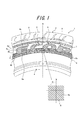
- FIG. 1 is a partial side view and a partially enlarged view of a tire showing an embodiment of a pneumatic tire according to the present invention.
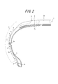
- FIG. 2 is a half sectional view of the tire shown in FIG. 1 in the meridian direction.
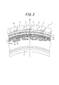
- FIG. 3 is a partial side view of a tire showing another embodiment of a pneumatic tire according to the present invention. It is a principal part enlarged view of FIG. 2 which shows the arrangement
- the product tire 1 includes a tread portion 2, a pair of sidewall portions 3 and a bead portion 4, a carcass 5 extending toroidally between the pair of bead portions 4, and comprising at least one ply cord layer, and the carcass 5.
- the belt 6 is disposed between the crown region 5a and the tread rubber 2a, and the side portion 5b of the carcass 5 is arranged around the bead core 4a disposed on the bead portion 4 from the inside in the tire width direction to the outside.
- the folded end 5 c is positioned on the tire side portion 7.
- the tire side portion 7 refers to a range from the outer edge in the tire width direction of the tread portion 2 to the rim fitting portion of the bead portion 4.
- the rubber gauge t (the rubber thickness from the ply cord to the outer surface of the tire side portion 7) of the tire side portion 7 at the folded end 5c shown in FIG. 1 is about 1.5 mm to 3.0 mm.
- an annular decorative band 8 is formed on the outer surface 7 a of the tire side portion 7 by a plurality of ridges 8 a arranged in the tire circumferential direction.
- the ridge 8a can be extended in a straight line parallel to the tire meridian M or inclined at a predetermined angle ⁇ , and can be curved with a predetermined curvature to extend in a curved line. It can also be.
- marks 9 made of predetermined characters, symbols or figures are arranged on the outer surface 7a. As shown in FIG. 1, the mark 9 is disposed so as to protrude outward in the tire radial direction from the position overlapping with the decorative band 8, or as illustrated in FIG. To do.
- the decorative band 8 is disposed over both the inner side and the outer side in the tire radial direction at the position corresponding to the turn-back end 5 c with reference to the position corresponding to the turn-back end 5 c of the carcass.
- the width w in the radial direction of the decorative band 8 shown in FIG. 1 is narrower than the longest radial direction length of the tire among the marks 9 arranged so as to overlap the decorative band 8. Yes.
- the unevenness appearing around the position corresponding to the folded end 5c of the outer surface 7a can be made inconspicuous with the decorative band 8 even if the rubber cage is made thin to some extent, and the width w of the decorative band 8 itself Can be minimized.
- the width w of the decorative band 8 can be about 4 to 20 mm.
- the mark 9 is arranged across both the portion where the decorative band 8 exists and the portion where the decorative band 8 does not exist. Since the background of the mark 9 is, the difference between the mark 9 and the background is more conspicuous, and the visibility can be sufficiently enhanced.
- the marks 9 are arranged so as to protrude outward in the tire radial direction from the decorative band 8 as shown in FIG. 1, even when a plurality of the marks 9 are arranged in the tire circumferential direction, the adjacent marks 9 are mutually connected. Since there is a margin in the interval between them and the size of the mark 9 can be increased, the visibility of the mark 9 can be further enhanced.
- the tire radial inner end 9 a or the tire radial outer end 9 b of the mark 9 overlaps the radially inner and outer boundary 8 b of the decorative band 8.
- the mark 9 has the tire radial inner end 9a shown in FIG. 1 or the tire radial outer end 9b shown in FIG. 3 aligned at a position corresponding to the turn-up end 5c of the carcass 5 in the tire side portion.
- the difference between the mark 9 and the background can be made more conspicuous.
- the raised ridge 9c is formed so as to protrude toward the outer surface of the tire from the ridge 9d in the mark, the raised ridge 9c effectively prevents damage to the ridge 9d in the mark. be able to.
- the outer surface 7 a is provided with a recess 8 c that is recessed toward the inner side in the tire width direction, and the ridge 8 a protrudes from the bottom of the recess 8 c and protrudes.
- the ridge 8a is effectively protected even if the periphery of the decorative band 8 is rubbed by a curb or the like during use of the tire.
- the angle ⁇ of the ridge 8a with respect to the tire meridian M is preferably inclined at 30 ° to 60 °.
- the existence of a rigid step is unavoidable.
- the angle ⁇ is too small, the extending direction of the ridge 8a is in the tire circumferential direction. Since the extending direction of the folded end 5c is close to the extending direction, there is a risk that cracks are likely to occur in the ridge 8a.
- the extending direction of the ridge 8a there is a concern that the effect of the ridge 8a that makes the unevenness appearing around the position corresponding to the turn-back end 5c of the tire side portion inconspicuous cannot be sufficiently exhibited because it becomes close to a right angle with respect to the extending direction of the end 5c.
- the unevenness caused by the presence of the folded end 5c can be more effectively made inconspicuous while maintaining sufficient strength of the tire.
- the tires 1 to 4 conforming to the present invention and the reference tire as a conventional example were prototyped, the visual check of the mark of each tire was performed, and the visibility of the mark was investigated.
- the results are shown in Table 1. Note that the visibility is obtained by indicating the survey results of each tire as an index using the survey results of the reference tire as a conventional example as a control, and the larger the number, the better the visibility.
- the conforming tire 1 is provided with a decorative band (the decorative band has a width of 16 mm) of 8 mm on each of the inner side and the outer side in the tire radial direction around the position corresponding to the folded end of the carcass in the tire side portion.
- the decorative band is formed by providing a ridge having an adjacent interval of 1.0 mm in a concave portion that is recessed 0.4 mm inward in the tire width direction from the outer surface of the tire side portion. It is formed so as to be flush with the concave portion (no ridge is provided in the mark).
- the conforming tire 2 is a tire equivalent to the conforming tire 1 except that the mark is arranged so that the radially inner end is located at the center of the decorative band.
- the conforming tire 3 is a tire equivalent to the conforming tire 2 except that the mark protrudes 0.4 mm outward from the outer surface of the tire side portion in the tire radial direction.
- the conforming tire 4 forms a raised ridge that borders the inside of the mark and borders the mark, and is adjacent to the surrounding area by the raised ridge within the mark having a distance of 0.8 mm.
- the tire is equivalent to the conforming tire 3 except that a ridge is provided.
- the reference tire is the same tire as the conforming tire 1 except that the width of the decorative band is 29 mm and the mark is disposed within the width of the decorative band.
- the width of the decorative band is made narrower than the maximum value in the tire radial direction of the mark, and the mark protrudes in the tire radial direction from the position overlapping the decorative band (applicable tires 1 to 4). ), It became clear that the visibility equal to or better than that of conventional tires can be secured.
Abstract
Description
なおここで、装飾帯の幅中央域とは、装飾帯の幅中央を中心として、タイヤ半径方向内側及び外側にこの装飾帯の幅の95%程度、好ましくは80%程度に亘る領域をいうものとする。 In such a tire, preferably, the inner end or the outer end in the tire radial direction in the overlapping region of the mark with the decorative band is disposed in the central width region of the decorative band.
Here, the width central region of the decorative band refers to a region extending about 95%, preferably about 80% of the width of the decorative band on the inner side and the outer side in the tire radial direction with the central width of the decorative band as the center. And
従ってこのタイヤによれば、標章の視認性をより向上させることができる。 In addition, when the mark is formed so as to protrude from the ridge of the decorative band toward the outer surface of the tire in an overlapping area with the decorative band of the mark, the mark can be made more conspicuous.
Therefore, according to this tire, the visibility of the mark can be further improved.
従ってこのタイヤによれば、さらに優れた標章の視認性を得ることができる。 Furthermore, when the mark is framed with a raised ridge and the ridge in the mark is provided in the surrounding area of the raised ridge, the mark can be made more conspicuous.
Therefore, according to this tire, even better visibility of the mark can be obtained.
この標章9は、図1に示すように、装飾帯8と重なる位置からタイヤ半径方向外側にはみ出させて配置するか、または、図3に示すように、タイヤ半径方向内側にはみ出させて配置する。 On the
As shown in FIG. 1, the
一方標章9は、図1及び図3に示すように、装飾帯8が存在する部分と存在しない部分の両方に跨がって配置されることになり、装飾帯8の有り無し部分の両方が標章9の背景となるので、標章9と背景との違いをより際立たせて、視認性を十分に高めることができる。
特に、標章9を、図1に示すように装飾帯8からタイヤ半径方向外側にはみ出して配置する場合は、標章9をタイヤ周方向に複数配置する場合でも、隣り合う標章9の相互間の間隔に余裕が生まれて、標章9のサイズを大きくすることができるので、標章9の視認性をより一層高めることができる。 Here, as shown in FIG. 2, the
On the other hand, as shown in FIGS. 1 and 3, the
In particular, when the
また、標章9は、図1に示すタイヤ半径方向内側端9aを、又は、図3に示すタイヤ半径方向外側端9bを、タイヤサイド部におけるカーカス5の折り返し端5cに対応する位置に揃えて配設することで、外表面7aの、折り返し端5cと対応する位置の周辺に現れる凹凸がより一層目立ちにくくなる。 And in the overlap area with the
Further, the

2 トレッド部
3 サイドウォール部
4 ビード部
4a ビードコア
5 カーカス
5c カーカスの折り返し端
6 ベルト
7 タイヤサイド部
7a タイヤサイド部の外表面
8 装飾帯
8a リッジ
8b 境界線
8c 凹部
9 標章
9a 標章のタイヤ半径方向内側端
9b 標章のタイヤ半径方向外側端
9c 隆起突条
9d 標章内リッジ DESCRIPTION OF SYMBOLS 1
Claims (6)
- タイヤサイド部の外表面に、多数本のリッジにて形成される円環状の装飾帯と、所定の文字、記号又は図形からなる、1つ以上の標章とを備える空気入りタイヤにおいて、
前記装飾帯を、カーカスの折り返し端と対応する位置からタイヤ半径方向内側及び外側の両側に亘って配設するとともに、装飾帯の幅を、該装飾帯に重ねて配設される標章の、タイヤ半径方向長さの最大値よりも狭くしてなり、前記標章を、前記装飾帯と重なる位置からタイヤ半径方向外側、又は内側の何れか一方に、はみ出させて配置してなる空気入りタイヤ。 In a pneumatic tire provided with an annular decorative band formed of a large number of ridges and one or more marks made of predetermined characters, symbols or figures on the outer surface of the tire side portion,
The decorative band is disposed from both the inner side and the outer side in the tire radial direction from the position corresponding to the folded end of the carcass, and the width of the decorative band is superimposed on the decorative band. A pneumatic tire, which is narrower than the maximum length in the tire radial direction, and is arranged so that the mark protrudes from the position overlapping with the decorative band to either the outer side or the inner side in the tire radial direction. . - 前記標章の、前記装飾帯との重なり域におけるタイヤ半径方向内側端又は外側端を、前記装飾帯の幅中央域に位置させてなる請求項1記載の空気入りタイヤ。 The pneumatic tire according to claim 1, wherein an inner end or an outer end in a tire radial direction in an overlapping area of the mark with the decorative band is located in a central width region of the decorative band.
- 前記標章を、タイヤ半径方向外側にはみ出させて配置してなる請求項1又は2に記載の空気入りタイヤ The pneumatic tire according to claim 1 or 2, wherein the mark is disposed so as to protrude outward in the tire radial direction.
- 前記標章の装飾帯との重なり域で、該標章を、装飾帯のリッジより外表面へ迫り出させて形成してなる請求項1~3の何れかに記載の空気入りタイヤ。 The pneumatic tire according to any one of claims 1 to 3, wherein the mark is formed by protruding from the ridge of the decorative band to the outer surface in an overlapping area with the decorative band of the mark.
- 前記標章を、隆起突条で縁取りし、該隆起突条による囲繞域に標章内リッジを設けてなる請求項1~4の何れかに記載の空気入りタイヤ。 The pneumatic tire according to any one of claims 1 to 4, wherein the mark is trimmed with a raised ridge, and a ridge in the mark is provided in an area surrounded by the raised ridge.
- 装飾帯のリッジを、タイヤ子午線に対して30°~60°の範囲で傾斜させてなる請求項1~5の何れかに記載の空気入りタイヤ。 The pneumatic tire according to any one of claims 1 to 5, wherein the ridge of the decorative band is inclined in a range of 30 ° to 60 ° with respect to the tire meridian.
Priority Applications (4)
| Application Number | Priority Date | Filing Date | Title |
|---|---|---|---|
| CN201180049228.4A CN103167962B (en) | 2010-08-31 | 2011-08-12 | Pneumatic tire |
| US13/819,571 US20130228261A1 (en) | 2010-08-31 | 2011-08-12 | Pneumatic tire |
| EP11821264.6A EP2612771B1 (en) | 2010-08-31 | 2011-08-12 | Pneumatic tire |
| JP2012531667A JPWO2012029239A1 (en) | 2010-08-31 | 2011-08-12 | Pneumatic tire |
Applications Claiming Priority (2)
| Application Number | Priority Date | Filing Date | Title |
|---|---|---|---|
| JP2010-193933 | 2010-08-31 | ||
| JP2010193933 | 2010-08-31 |
Publications (1)
| Publication Number | Publication Date |
|---|---|
| WO2012029239A1 true WO2012029239A1 (en) | 2012-03-08 |
Family
ID=45772366
Family Applications (1)
| Application Number | Title | Priority Date | Filing Date |
|---|---|---|---|
| PCT/JP2011/004575 WO2012029239A1 (en) | 2010-08-31 | 2011-08-12 | Pneumatic tire |
Country Status (5)
| Country | Link |
|---|---|
| US (1) | US20130228261A1 (en) |
| EP (1) | EP2612771B1 (en) |
| JP (1) | JPWO2012029239A1 (en) |
| CN (1) | CN103167962B (en) |
| WO (1) | WO2012029239A1 (en) |
Cited By (4)
| Publication number | Priority date | Publication date | Assignee | Title |
|---|---|---|---|---|
| JP2014125108A (en) * | 2012-12-26 | 2014-07-07 | Sumitomo Rubber Ind Ltd | Pneumatic tire |
| JP6465192B1 (en) * | 2017-11-20 | 2019-02-06 | 横浜ゴム株式会社 | Pneumatic tire |
| WO2019240053A1 (en) * | 2018-06-15 | 2019-12-19 | 株式会社ブリヂストン | Tire |
| JP2021024439A (en) * | 2019-08-05 | 2021-02-22 | 横浜ゴム株式会社 | Pneumatic tire |
Families Citing this family (3)
| Publication number | Priority date | Publication date | Assignee | Title |
|---|---|---|---|---|
| FR3014365B1 (en) * | 2013-12-11 | 2017-01-13 | Michelin & Cie | PNEUMATIC COMPRISING A PARTICULAR GRAPHICAL ELEMENT |
| JP7099945B2 (en) * | 2018-12-18 | 2022-07-12 | 株式会社ブリヂストン | Pneumatic tires |
| CN113891811A (en) * | 2019-08-05 | 2022-01-04 | 横滨橡胶株式会社 | Pneumatic tire |
Citations (7)
| Publication number | Priority date | Publication date | Assignee | Title |
|---|---|---|---|---|
| JPS63106109A (en) * | 1986-10-24 | 1988-05-11 | Bridgestone Corp | Pneumatic tyre |
| JPH092028A (en) | 1995-04-19 | 1997-01-07 | Bridgestone Corp | Pneumatic tire provided with decorative body composed of many ridges |
| JPH11321241A (en) * | 1998-04-17 | 1999-11-24 | Bridgestone Corp | Tire side wall |
| JP2003191719A (en) * | 2001-12-27 | 2003-07-09 | Bridgestone Corp | Pneumatic tire |
| JP2007045328A (en) * | 2005-08-10 | 2007-02-22 | Bridgestone Corp | Pneumatic tire |
| JP2010064656A (en) * | 2008-09-11 | 2010-03-25 | Bridgestone Corp | Pneumatic tire |
| JP2010137604A (en) * | 2008-12-09 | 2010-06-24 | Toyo Tire & Rubber Co Ltd | Pneumatic tire |
Family Cites Families (13)
| Publication number | Priority date | Publication date | Assignee | Title |
|---|---|---|---|---|
| JPH066967Y2 (en) * | 1984-04-03 | 1994-02-23 | 住友ゴム工業株式会社 | tire |
| JPS63106108A (en) * | 1986-10-24 | 1988-05-11 | Bridgestone Corp | Pneumatic tyre |
| JP3831072B2 (en) * | 1997-07-08 | 2006-10-11 | 株式会社ブリヂストン | Pneumatic tire with a decorative body consisting of many ridges |
| JP4295455B2 (en) * | 2001-10-19 | 2009-07-15 | 住友ゴム工業株式会社 | Pneumatic tire |
| EP1310384B1 (en) * | 2001-11-08 | 2014-01-29 | Sumitomo Rubber Industries, Ltd. | Vehicle tire |
| JP2005125937A (en) * | 2003-10-23 | 2005-05-19 | Bridgestone Corp | Sidewall decorative structure of tire |
| WO2007136091A1 (en) * | 2006-05-24 | 2007-11-29 | The Yokohama Rubber Co., Ltd. | Pneumatic tire |
| JP4036269B2 (en) * | 2006-05-24 | 2008-01-23 | 横浜ゴム株式会社 | Pneumatic tire |
| JP2008189165A (en) * | 2007-02-05 | 2008-08-21 | Yokohama Rubber Co Ltd:The | Pneumatic tire |
| JP5026840B2 (en) * | 2007-04-03 | 2012-09-19 | 東洋ゴム工業株式会社 | Pneumatic tire |
| JP2009143488A (en) * | 2007-12-17 | 2009-07-02 | Sumitomo Rubber Ind Ltd | Pneumatic tire |
| JP5160345B2 (en) * | 2008-08-26 | 2013-03-13 | 東洋ゴム工業株式会社 | Pneumatic tire |
| JP2010179830A (en) * | 2009-02-06 | 2010-08-19 | Bridgestone Corp | Pneumatic tire |
-
2011
- 2011-08-12 EP EP11821264.6A patent/EP2612771B1/en not_active Not-in-force
- 2011-08-12 US US13/819,571 patent/US20130228261A1/en not_active Abandoned
- 2011-08-12 JP JP2012531667A patent/JPWO2012029239A1/en active Pending
- 2011-08-12 WO PCT/JP2011/004575 patent/WO2012029239A1/en active Application Filing
- 2011-08-12 CN CN201180049228.4A patent/CN103167962B/en not_active Expired - Fee Related
Patent Citations (7)
| Publication number | Priority date | Publication date | Assignee | Title |
|---|---|---|---|---|
| JPS63106109A (en) * | 1986-10-24 | 1988-05-11 | Bridgestone Corp | Pneumatic tyre |
| JPH092028A (en) | 1995-04-19 | 1997-01-07 | Bridgestone Corp | Pneumatic tire provided with decorative body composed of many ridges |
| JPH11321241A (en) * | 1998-04-17 | 1999-11-24 | Bridgestone Corp | Tire side wall |
| JP2003191719A (en) * | 2001-12-27 | 2003-07-09 | Bridgestone Corp | Pneumatic tire |
| JP2007045328A (en) * | 2005-08-10 | 2007-02-22 | Bridgestone Corp | Pneumatic tire |
| JP2010064656A (en) * | 2008-09-11 | 2010-03-25 | Bridgestone Corp | Pneumatic tire |
| JP2010137604A (en) * | 2008-12-09 | 2010-06-24 | Toyo Tire & Rubber Co Ltd | Pneumatic tire |
Non-Patent Citations (1)
| Title |
|---|
| See also references of EP2612771A4 * |
Cited By (10)
| Publication number | Priority date | Publication date | Assignee | Title |
|---|---|---|---|---|
| JP2014125108A (en) * | 2012-12-26 | 2014-07-07 | Sumitomo Rubber Ind Ltd | Pneumatic tire |
| JP6465192B1 (en) * | 2017-11-20 | 2019-02-06 | 横浜ゴム株式会社 | Pneumatic tire |
| WO2019098275A1 (en) * | 2017-11-20 | 2019-05-23 | 横浜ゴム株式会社 | Pneumatic tire |
| JP2019093771A (en) * | 2017-11-20 | 2019-06-20 | 横浜ゴム株式会社 | Pneumatic tire |
| US11407258B2 (en) | 2017-11-20 | 2022-08-09 | The Yokohama Rubber Co., Ltd. | Pneumatic tire |
| WO2019240053A1 (en) * | 2018-06-15 | 2019-12-19 | 株式会社ブリヂストン | Tire |
| JP2019217818A (en) * | 2018-06-15 | 2019-12-26 | 株式会社ブリヂストン | tire |
| JP7006522B2 (en) | 2018-06-15 | 2022-01-24 | 株式会社ブリヂストン | tire |
| JP2021024439A (en) * | 2019-08-05 | 2021-02-22 | 横浜ゴム株式会社 | Pneumatic tire |
| JP7207224B2 (en) | 2019-08-05 | 2023-01-18 | 横浜ゴム株式会社 | pneumatic tire |
Also Published As
| Publication number | Publication date |
|---|---|
| CN103167962A (en) | 2013-06-19 |
| US20130228261A1 (en) | 2013-09-05 |
| EP2612771B1 (en) | 2018-11-14 |
| CN103167962B (en) | 2016-05-11 |
| JPWO2012029239A1 (en) | 2013-10-28 |
| EP2612771A1 (en) | 2013-07-10 |
| EP2612771A4 (en) | 2014-05-14 |
Similar Documents
| Publication | Publication Date | Title |
|---|---|---|
| WO2012029239A1 (en) | Pneumatic tire | |
| JP5793159B2 (en) | Pneumatic tire | |
| JP6747932B2 (en) | Pneumatic tire | |
| AU2011249396B2 (en) | Pneumatic tire | |
| JP5802236B2 (en) | Pneumatic tire | |
| JP2012131283A (en) | Pneumatic tire | |
| CN104057787A (en) | Pneumatic tire | |
| JP6232844B2 (en) | Pneumatic tire | |
| JP5232580B2 (en) | Pneumatic tire | |
| JP2019196152A (en) | Pneumatic tire | |
| JP5394679B2 (en) | Pneumatic tire | |
| WO2019098275A1 (en) | Pneumatic tire | |
| CN112423999B (en) | Pneumatic tire | |
| JP7443764B2 (en) | pneumatic tires | |
| JP2003170710A (en) | Pneumatic tire | |
| CN112384381B (en) | Pneumatic tire | |
| JP2002211214A (en) | Pneumatic tire | |
| JPS60128006A (en) | Radial tyre with improved side part | |
| JP5241248B2 (en) | Pneumatic tire | |
| JP2021091330A (en) | Pneumatic tire | |
| JP2021104745A (en) | Pneumatic tire | |
| USD989703S1 (en) | Tire sidewall | |
| USD1006724S1 (en) | Tire sidewall | |
| JP2009143403A (en) | Pneumatic tire and its manufacturing method | |
| JP6018882B2 (en) | tire |
Legal Events
| Date | Code | Title | Description |
|---|---|---|---|
| WWE | Wipo information: entry into national phase |
Ref document number: 201180049228.4 Country of ref document: CN |
|
| 121 | Ep: the epo has been informed by wipo that ep was designated in this application |
Ref document number: 11821264 Country of ref document: EP Kind code of ref document: A1 |
|
| WWE | Wipo information: entry into national phase |
Ref document number: 2012531667 Country of ref document: JP |
|
| WWE | Wipo information: entry into national phase |
Ref document number: 2011821264 Country of ref document: EP |
|
| NENP | Non-entry into the national phase |
Ref country code: DE |
|
| WWE | Wipo information: entry into national phase |
Ref document number: 13819571 Country of ref document: US |