WO2011027441A1 - 車両制動力制御装置 - Google Patents
車両制動力制御装置 Download PDFInfo
- Publication number
- WO2011027441A1 WO2011027441A1 PCT/JP2009/065392 JP2009065392W WO2011027441A1 WO 2011027441 A1 WO2011027441 A1 WO 2011027441A1 JP 2009065392 W JP2009065392 W JP 2009065392W WO 2011027441 A1 WO2011027441 A1 WO 2011027441A1
- Authority
- WO
- WIPO (PCT)
- Prior art keywords
- braking force
- control device
- vehicle braking
- force control
- engine
- Prior art date
Links
Images

Classifications
-
- B—PERFORMING OPERATIONS; TRANSPORTING
- B60—VEHICLES IN GENERAL
- B60T—VEHICLE BRAKE CONTROL SYSTEMS OR PARTS THEREOF; BRAKE CONTROL SYSTEMS OR PARTS THEREOF, IN GENERAL; ARRANGEMENT OF BRAKING ELEMENTS ON VEHICLES IN GENERAL; PORTABLE DEVICES FOR PREVENTING UNWANTED MOVEMENT OF VEHICLES; VEHICLE MODIFICATIONS TO FACILITATE COOLING OF BRAKES
- B60T8/00—Arrangements for adjusting wheel-braking force to meet varying vehicular or ground-surface conditions, e.g. limiting or varying distribution of braking force
- B60T8/17—Using electrical or electronic regulation means to control braking
- B60T8/176—Brake regulation specially adapted to prevent excessive wheel slip during vehicle deceleration, e.g. ABS
- B60T8/1761—Brake regulation specially adapted to prevent excessive wheel slip during vehicle deceleration, e.g. ABS responsive to wheel or brake dynamics, e.g. wheel slip, wheel acceleration or rate of change of brake fluid pressure
- B60T8/17616—Microprocessor-based systems
-
- B—PERFORMING OPERATIONS; TRANSPORTING
- B60—VEHICLES IN GENERAL
- B60W—CONJOINT CONTROL OF VEHICLE SUB-UNITS OF DIFFERENT TYPE OR DIFFERENT FUNCTION; CONTROL SYSTEMS SPECIALLY ADAPTED FOR HYBRID VEHICLES; ROAD VEHICLE DRIVE CONTROL SYSTEMS FOR PURPOSES NOT RELATED TO THE CONTROL OF A PARTICULAR SUB-UNIT
- B60W10/00—Conjoint control of vehicle sub-units of different type or different function
- B60W10/04—Conjoint control of vehicle sub-units of different type or different function including control of propulsion units
- B60W10/06—Conjoint control of vehicle sub-units of different type or different function including control of propulsion units including control of combustion engines
-
- B—PERFORMING OPERATIONS; TRANSPORTING
- B60—VEHICLES IN GENERAL
- B60T—VEHICLE BRAKE CONTROL SYSTEMS OR PARTS THEREOF; BRAKE CONTROL SYSTEMS OR PARTS THEREOF, IN GENERAL; ARRANGEMENT OF BRAKING ELEMENTS ON VEHICLES IN GENERAL; PORTABLE DEVICES FOR PREVENTING UNWANTED MOVEMENT OF VEHICLES; VEHICLE MODIFICATIONS TO FACILITATE COOLING OF BRAKES
- B60T2201/00—Particular use of vehicle brake systems; Special systems using also the brakes; Special software modules within the brake system controller
- B60T2201/09—Engine drag compensation
-
- B—PERFORMING OPERATIONS; TRANSPORTING
- B60—VEHICLES IN GENERAL
- B60T—VEHICLE BRAKE CONTROL SYSTEMS OR PARTS THEREOF; BRAKE CONTROL SYSTEMS OR PARTS THEREOF, IN GENERAL; ARRANGEMENT OF BRAKING ELEMENTS ON VEHICLES IN GENERAL; PORTABLE DEVICES FOR PREVENTING UNWANTED MOVEMENT OF VEHICLES; VEHICLE MODIFICATIONS TO FACILITATE COOLING OF BRAKES
- B60T2260/00—Interaction of vehicle brake system with other systems
- B60T2260/04—Automatic transmission
-
- B—PERFORMING OPERATIONS; TRANSPORTING
- B60—VEHICLES IN GENERAL
- B60T—VEHICLE BRAKE CONTROL SYSTEMS OR PARTS THEREOF; BRAKE CONTROL SYSTEMS OR PARTS THEREOF, IN GENERAL; ARRANGEMENT OF BRAKING ELEMENTS ON VEHICLES IN GENERAL; PORTABLE DEVICES FOR PREVENTING UNWANTED MOVEMENT OF VEHICLES; VEHICLE MODIFICATIONS TO FACILITATE COOLING OF BRAKES
- B60T8/00—Arrangements for adjusting wheel-braking force to meet varying vehicular or ground-surface conditions, e.g. limiting or varying distribution of braking force
- B60T8/17—Using electrical or electronic regulation means to control braking
- B60T8/176—Brake regulation specially adapted to prevent excessive wheel slip during vehicle deceleration, e.g. ABS
- B60T8/1761—Brake regulation specially adapted to prevent excessive wheel slip during vehicle deceleration, e.g. ABS responsive to wheel or brake dynamics, e.g. wheel slip, wheel acceleration or rate of change of brake fluid pressure
Definitions
- the present invention relates to a vehicle braking force control device that performs antilock brake control of a brake device.
- a braking force by an engine brake acts in addition to the braking force by the braking device. Even when the braking force by the engine brake is applied, the load on the rear wheel is reduced by moving the load on the vehicle to the front wheel side as in the case of operating the brake device, and the rear wheel is likely to slip Become. Therefore, for example, in a rear-wheel-drive automobile or motorcycle, when the rear wheel is slipped by the engine brake at cornering, fuel supply to the engine is resumed to reduce the braking force by the engine brake.
- a vehicle braking force control device for controlling the braking force of the front wheels according to the slip state of the rear wheels is proposed because the driver can not obtain the feeling of deceleration expected (for example, see Patent Document 1). .
- the antilock brake control intervenes even if the braking device is not braked. It will Even if the driver brakes the brake system in such a state, the braking of the brake system is delayed or difficult to brake due to the intervention of the antilock brake control. Therefore, when a large braking force is generated by the engine brake, it is difficult to brake the brake device as the driver's image suggests.
- the object of the present invention is to solve the problems of the above-mentioned prior art, and to brake the braking device as the driver imagines, even under a situation where a large braking force by the engine brake is applied. It is providing a vehicle braking force control device.
- the present invention relates to a vehicle braking force control device mounted on a vehicle and performing antilock brake control when the wheel slip ratio becomes equal to or greater than a predetermined threshold value during normal times, the accelerator opening signal corresponding to the accelerator opening;
- a clutch connection signal corresponding to the connected state of the clutch and a power transmission signal corresponding to the power transmission state of the transmission are acquired from the engine control unit, and based on the accelerator opening degree signal, the clutch connected signal and the power transmission signal.
- the predetermined threshold value is changed to an offset threshold value that makes the antilock brake control more difficult to perform than the normal time.
- the change of the threshold may be maintained for a predetermined time.
- the accelerator opening degree decreases by a predetermined opening degree or more within a predetermined time
- the clutch is in the connected state, and the transmission is in the power transmission state, it may be determined that the action of the engine brake is large.
- the accelerator opening degree is in a substantially fully closed state from a state where the accelerator opening degree is equal to or more than a predetermined value, it may be determined that the accelerator opening degree has decreased by a predetermined opening degree or more within a predetermined time.
- an engine speed signal corresponding to the engine speed is further acquired, the transmission is downshifted, the accelerator opening degree is substantially fully closed, the clutch is connected, and the transmission is motive power. It may be determined that the action of the engine brake is large when in the transmission state and the engine speed is rising above the predetermined speed.
- the change of the threshold may be maintained while the engine speed is increased above a predetermined speed.
- the offset threshold when the shift down is performed may be harder to perform the antilock brake control than the offset threshold when the shift down is not performed.
- the offset threshold when the shift down is performed may be longer than the offset threshold when the shift down is not performed, for a longer time while the predetermined threshold is maintained at the offset threshold.
- the offset amount of the offset threshold may be gradually reduced.
- the predetermined threshold may be changed to the offset threshold when being turned on.
- the accelerator opening degree signal, the clutch connection signal, and the power transmission signal may be acquired from the engine control unit.
- the braking device can be braked as the driver's image.
- FIG. 2 is a block diagram showing an ABS-ECU according to an embodiment of the present invention and an engine ECU etc. connected thereto.
- 10 is a graph showing an outline of threshold value change processing by the ABS-ECU 100 when an engine brake with a large braking force is detected. It is a graph which shows the offset amount of offset threshold value when sudden throttle off is detected. It is a graph which shows the change of the threshold value when it is changed into an offset threshold value.
- 10 is a flowchart showing an operation when the ABS-ECU 100 detects a sudden throttle off by the driver and changes the threshold value. It is a graph which shows the amount of offsets of offset threshold when downshift is detected. 10 is a flowchart showing an operation when the ABS-ECU 100 detects a downshift operation by the driver and changes the threshold value.
- FIG. 1 is a block diagram showing an ABS-ECU and an engine ECU etc. connected thereto.
- the ABS-ECU 100 as a braking force control device for a vehicle is mainly mounted on a motorcycle vehicle, and is used in a braking system to restore wheel grip when the wheel slip ratio becomes equal to or greater than a predetermined threshold value at the time of braking. It is a control device for performing antilock brake control.
- the ABS-ECU 100 is electrically connected to an engine ECU 10 as an engine control unit that controls the engine by a connection wiring 20.
- the ABS-ECU 100 is electrically connected to the front wheel pressure reducing valve 1, the rear wheel pressure reducing valve 2, the front wheel holding valve 3, the rear wheel holding valve 4, the pump motor 5, the front wheel speed sensor 6, and the rear wheel speed sensor 7. There is.
- the front wheel pressure reducing valve 1, the rear wheel pressure reducing valve 2, the front wheel holding valve 3 and the rear wheel holding valve 4 are control valves.
- the ABS-ECU 100 performs antilock brake control of the front wheels by outputting drive signals to the front wheel pressure reducing valve 1 and the front wheel holding valve 3 for control.
- the ABS-ECU 100 performs antilock brake control on the rear wheels by outputting drive signals to the rear wheel pressure reducing valve 2 and the rear wheel holding valve 4 for control.
- the pump motor 5 is a motor for driving a hydraulic pump (not shown).
- the ABS-ECU 100 is a master cylinder on which the front wheel pressure reducing valve 1, the rear wheel pressure reducing valve 2, the front wheel holding valve 3 and the rear wheel holding valve 4 are attached by controlling the hydraulic pump by outputting a drive signal to the pump motor 5. Return the brake fluid to.
- the front wheel speed sensor 6 and the rear wheel speed sensor 7 detect the wheel speeds of the front and rear wheels of the vehicle, and output the detected wheel speeds to the ABS-ECU 100 as wheel speed signals.
- the ABS-ECU 100 calculates the vehicle speed and the front or rear wheel slip ratio ((car speed-wheel speed) / car speed) based on the acquired wheel speed signal.
- the ABS-ECU 100 calculates the vehicle speed based on the front wheel speed and the rear wheel speed, and regards this vehicle speed as the speed at which the vehicle travels.
- the engine ECU 10 is electrically connected to an engine rotational speed sensor 11, an accelerator opening degree sensor 12, a clutch switch 13, and a gear position sensor 14.
- the engine speed sensor 11 detects the engine speed of an unshown engine mounted on the vehicle, and outputs an engine speed signal corresponding to the engine speed to the engine ECU 10.
- the accelerator opening sensor 12 is a throttle position sensor or the like, but the accelerator opening may be determined based on the flow rate measured by a flow meter such as an air flow sensor.
- the accelerator opening sensor 12 detects the degree of opening of the slot valve, that is, the accelerator opening, and outputs an accelerator opening signal corresponding to the accelerator opening to the engine ECU 10.
- the clutch switch 13 is a clutch sensor for detecting the physical connection state of the clutch disposed between the engine and the transmission, and a clutch ON / OFF signal (clutch connection signal corresponding to the connection state of the clutch to the engine ECU 10 Output).
- the gear position sensor 14 is a sensor for detecting a power transmission state of the transmission, that is, a gear position, and outputs a gear position signal (power transmission signal) corresponding to the power transmission state of the transmission to the engine ECU 10.
- the ABS-ECU 100 can acquire an engine rotation number signal, an accelerator opening degree signal, a clutch ON / OFF signal, and a gear position signal from the engine ECU 10 through the connection wiring 20.
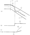
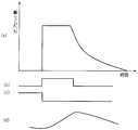
- FIG. 2 is a graph showing an outline of threshold value change processing by the ABS-ECU 100 when an engine brake with a large braking force is detected.
- FIG. 2 (a) shows the correspondence between the wheel speed and the time
- FIG. 2 (b) shows the correspondence between the signal for detecting execution of the antilock brake control and time
- c) shows the correspondence between the brake pressure of the brake device and time.
- the horizontal axes in FIG. 2 (a) to FIG. 2 (c) agree with the passage of time.
- the vertical axis represents the wheel speed of the front wheels
- the horizontal axis represents the time.
- the accelerator opening is suddenly closed at time A and the engine brake is applied.
- the vertical axis represents the wheel speed of the rear wheel
- the horizontal axis represents the time.
- the engine brake acts on the rear wheels which are drive wheels, so that after time A, the rear wheel speed is slower than the front wheel speed. That is, although the front wheels are kept gripped as indicated by line L1, the rear wheels are slipped as indicated by line L2, and there is a difference between the front wheels and the wheel speeds.
- a line L3 is a threshold value including a slip ratio for determining whether or not to perform anti-lock brake control at normal times. Under normal conditions, antilock brake control is performed when the rear wheel reaches a slip ratio indicated by line L3.
- Line L3 is set to have a substantially constant interval with the vehicle speed.
- Line L4 in FIG. 2B indicates whether or not antilock brake control is being performed, and indicates that the portion that is one step higher is performing antilock brake control.
- the line L2 and the line L3 intersect at time B, that is, the rear wheel speed reaches the threshold value by the line L3, and as shown in FIG. 2 (b), From time B, it can be seen that antilock brake control is being performed.
- a line L5 in FIG. 2 (c) indicates a brake input that the driver imagines, that is, an operation of the brake lever by the driver.
- line L6 indicates the change of the actual brake input, that is, the brake pressure of the brake system. Since the rear wheel slips and antilock brake control is executed from time B, it can be seen that the brake input that the driver imagines is different from the actual brake input as shown by line L5 and line L6. As a result, when a large braking force by the engine brake is applied, it is difficult to brake the brake device as the driver's image suggests.
- a line L7 in FIG. 2A indicates a state in which the ABS-ECU 100 changes the threshold value including the slip ratio for determining whether or not to perform the antilock brake control to the offset threshold value.
- the ABS-ECU 100 determines that the action of the engine brake is large based on the engine speed signal, the accelerator opening signal, the clutch ON / OFF signal, and the gear position signal, as shown by line L7, the offset is offset by the threshold value. Temporarily change the threshold to the threshold. As a result, the slip ratio when it is determined that the antilock brake control is to be performed is increased. As shown in FIG.
- the line L2 does not intersect with the line L7, that is, it does not reach a threshold consisting of a slip ratio for determining whether or not to perform antilock brake control. Therefore, the ABS-ECU 100 changes the threshold for performing antilock braking control to the offset threshold, thereby making it more difficult to perform antilock braking control than in the case of line L3, which is a normal threshold.
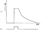
- FIG. 3 is a graph showing the offset amount of the offset threshold when a sudden throttle-off is detected
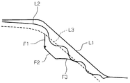
- FIG. 4 is a graph showing changes in the threshold when changed to the offset threshold.
- FIG. 3 (a) shows the correspondence between the offset amount and the elapsed time
- FIG. 3 (b) shows the correspondence between the signal for detecting the throttle off and the time.
- the horizontal axes in FIG. 3 (a) and FIG. 3 (b) coincide with each other over time.
- the offset threshold when a sudden throttle-off is detected keeps the offset amount substantially constant while the throttle-off is detected, and the offset amount is set when the throttle-off detection is completed.
- the threshold is offset to decrease gently.
- the change to the offset threshold is maintained only while the throttle off is detected, but the change to the offset threshold may be maintained even after the throttle off is not detected, for example. .
- the ABS-ECU 100 changes, for example, the offset amount of the offset threshold and the offset time according to the gear position of the transmission. By doing this, it is possible to make the offset threshold more appropriate.
- the offset threshold value corresponding to each gear position is larger as the gear position is lower, that is, as the gear position is higher, the offset amount is longer and the offset time is longer, and as the gear position is higher, that is, It is desirable that the lower the gear ratio, the smaller the offset amount and the shorter the offset time.
- the ABS-ECU 100 changes the threshold to the offset threshold as indicated by the line F1 according to the offset threshold as shown in FIG. 4 and as indicated by the line F2 while detecting the throttle off.
- the offset amount is kept constant, and when the detection of throttle-off is completed, the offset amount is gradually reduced along the normal threshold before the offset and is returned to the original normal threshold as shown by line F3.
- the threshold for determining whether to perform antilock brake control is temporarily changed to the offset threshold.
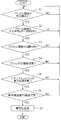
- FIG. 5 is a flowchart showing an operation when the ABS-ECU 100 detects a sudden throttle off by the driver and changes the threshold.
- the ABS-ECU 100 determines whether the accelerator opening degree is equal to or more than a predetermined value (step S1).
- the predetermined value of the accelerator opening used for the determination is the accelerator opening large enough for the engine brake with a large braking force to act when the accelerator opening is closed, that is, when the throttle is off. And is arbitrarily set.
- step S1 determines whether the accelerator opening is fully closed within the predetermined time (step S2). ).
- the predetermined time when the accelerator opening is fully closed, the time required for the accelerator opening to be fully closed from the accelerator opening in step S1 is sufficient for the engine brake with a large braking force to act Size of time.
- step S1: NO the ABS-ECU 100 repeats the process of step S1.
- step S3 determines whether the accelerator opening is fully closed.
- the fully-closed state in step S2 and the fully-closed state in step S3 have different thresholds for determining that they are in the fully-closed state, and the fully-closed state in step S3 is more closed. There is less air flow into the air. Note that both fully closed states include not only the state in which the throttle is completely closed but also a state in which the throttle is slightly open.
- step S2 NO
- the ABS-ECU 100 repeats a series of processing from step S1.
- step S3 determines whether the clutch is in the connected state (step S4). On the other hand, if it is determined in step S3 that the accelerator opening is not in the fully closed state (step S3: NO), the ABS-ECU 100 repeats a series of processing from step S1.
- step S4 determines whether the transmission is in the power transmission state (step S5).
- the power transmission state of the transmission means a state in which the transmission is not shifted to neutral.
- step S4: NO the ABS-ECU 100 repeats a series of processing from step S1.
- step S5 determines whether the vehicle deceleration is in the deceleration state (step S6).
- step S6 determines whether the vehicle deceleration is in the deceleration state.
- step S5 determines whether the vehicle deceleration is in a decelerating state means that the vehicle is not in an accelerating state.
- step S5: NO the ABS-ECU 100 repeats a series of processing from step S1.
- step S6 When it is determined in step S6 that the vehicle deceleration is in the decelerating state (step S6: YES), the ABS-ECU 100 determines a threshold for determining whether or not to perform antilock brake control at the time of a sudden accelerator off. The offset threshold is changed (step S7). On the other hand, when it is determined in step S6 that the vehicle deceleration is not in the deceleration state (step S6: NO), the ABS-ECU 100 repeats a series of processing from step S1.
- the ABS-ECU 100 determines that the action of the engine brake after the accelerator is released is large through steps S1 to S6, and the threshold for determining whether to perform the antilock brake control is a sudden accelerator off It can be changed to the time offset threshold.
- FIG. 6 is a graph showing the offset amount of the offset threshold when shift down is detected.
- 6 (a) shows the correspondence between the offset amount and the elapsed time
- FIG. 6 (b) shows the relationship between the signal for detecting the downshift and the time
- FIG. 6 (c) shows the gear of the transmission.
- the relationship between the signal for detecting the position and the time is shown
- FIG. 6D shows the correspondence between the signal for detecting the fluctuation of the engine speed and the time.
- the horizontal axes in FIG. 6 (a) to FIG. 6 (d) coincide with each other over time.
- the ABS-ECU 100 in the present embodiment changes the threshold for determining whether or not to perform the antilock brake control to the offset threshold simultaneously with the detection of the downshift and the change of the gear position.
- the offset threshold when the downshift in this embodiment is detected is kept substantially constant while the offset amount is large while the engine rotational speed is rising, and then the offset amount is determined.
- the threshold is offset so as to reduce it gradually. Note that the offset threshold at the time of downshift is usually higher than the offset threshold at the time of quick off, since the action of the engine brake is larger at downshift than at sudden off with no downshift. The offset amount is large, and the offset time is long.
- the offset threshold at the time of downshift is made common regardless of the gear position of the transmission before and after the downshift.
- the ABS-ECU 100 can make the offset threshold more appropriate, for example, by changing the offset amount of the offset threshold and the offset time according to the gear position before and after the shift down.
- the offset amount is the largest and the offset time is also the longest.
- the braking force of the engine brake such as downshifting from 6th to 5th is weak, that is, downshifting from the gear position with the lowest reduction ratio to the gear position with the next lower reduction ratio.
- the offset amount is the smallest and the offset time is also short.
- the offset threshold is set according to the strength of the braking force by the engine brake, for example, the downshift from second gear to first gear has a larger offset amount than the downshift from fourth gear to second gear. , Offset time will be longer.
- the ABS-ECU 100 may determine that it is a downshift from the sixth speed to the first speed when the shift down is sequentially from the sixth speed to the first speed within a predetermined time.
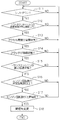
- FIG. 7 is a flowchart showing an operation when the ABS-ECU 100 detects a downshift operation by the driver and changes the threshold.
- the ABS-ECU 100 determines whether or not the gear position of the transmission has decreased, that is, whether or not the gear is downshifted (step S11).
- step S11 determines whether the elapsed time after the shift down is within a predetermined time (step S12).
- a predetermined time for example, that an engine brake that acts due to the effect of the downshift is sufficiently large to cause wheel slippage. It is in time.
- step S11: NO the ABS-ECU 100 repeats the process of step S11.
- step S12 determines whether the accelerator opening degree is fully closed (step S12). S13).
- the driver when downshifting is performed in order to increase the torque of the drive wheel on the uphill, the driver usually executes the process of step S13 to increase the accelerator opening degree immediately after downshifting. By doing this, it is possible to distinguish between downshifting on an uphill or the like and downshifting when entering a corner.
- step S12: NO the ABS-ECU 100 repeats a series of processing from step S11.
- step S13 determines whether the clutch is in the connected state (step S14). On the other hand, if it is determined in step S13 that the accelerator opening is not in the fully closed state (step S13: NO), the ABS-ECU 100 repeats a series of processing from step S11.
- step S14 determines whether the transmission is in the power transmission state (step S15). On the other hand, if it is determined in step S14 that the clutch is not in the connected state (step S14: NO), the ABS-ECU 100 repeats a series of processing from step S11.
- step S15 determines whether the engine speed is equal to or greater than a predetermined speed (step S16).
- the predetermined number of revolutions used for the determination may be distinguished from the number of revolutions area mainly used in a traveling state such as a so-called town riding. By performing the process of step S16, it is possible to distinguish between town riding and circuit driving or the like.
- step S15: NO the ABS-ECU 100 repeats a series of processing from step S11.
- step S16 determines whether the engine speed tends to increase (step S17).
- that the engine rotational speed tends to increase means an increase in the engine rotational speed that accompanies the reduction ratio of the transmission becoming large due to the downshift.
- step S16: NO the ABS-ECU 100 repeats a series of processes from step S11.
- step S17 If it is determined in step S17 that the engine rotational speed tends to increase (step S17: YES), the ABS-ECU 100 determines the threshold for determining whether or not to perform antilock brake control, the offset threshold at the time of shift down (Step S18). In addition, the state changed into the offset threshold value is maintained while the engine speed is rising above a predetermined speed. On the other hand, if it is determined in step S17 that the engine rotational speed does not tend to increase (step S17: NO), the ABS-ECU 100 repeats a series of processing from step S11.
- the ABS-ECU 100 determines that the action of the engine brake after downshifting is large through steps S11 to S17, and determines the threshold value for determining whether to perform antilock brake control at the time of downshifting. It can be changed to the offset threshold. Note that the ABS-ECU 100 selects the offset threshold with the larger offset threshold when judging that the accelerator is suddenly released and the shift down substantially simultaneously.
- the ABS-ECU 100 detects sudden throttle-off or down-shift, and changes the threshold for determining whether to perform antilock brake control to the offset threshold. As a result, it is possible to prevent unnecessary antilock brake control intervention that the driver does not want to intervene, so even under conditions where a large braking force by the engine brake is acting, according to the driver's image
- the braking device can be braked.
- the offset threshold is changed so as to smoothly decrease. As a result, it is possible to prevent the antilock brake control from suddenly engaging with the end of the offset, so it is possible to make it difficult for the driver to feel uncomfortable due to the offset of the antilock brake control threshold.
- ABS-ECU 100 is mounted on the motorcycle, but is not limited to this.
- the ABS-ECU 100 acquires the engine speed signal, the accelerator opening signal, the clutch ON / OFF signal, and the gear position signal from the engine ECU 10 via the connection wiring 20, but the present invention Is not limited to this.
- the ABS-ECU obtains an engine speed signal, an accelerator opening signal, a clutch ON / OFF signal, and a gear position signal directly from the engine rotation speed sensor, the accelerator opening sensor, the clutch switch and the gear position sensor. It is also good.
- the ABS-ECU 100 is connected to the engine ECU 10 via the connection wiring 20, but the present invention is not limited to this.
- the ABS-ECU 100 may be connected to the engine ECU, the engine speed sensor, the accelerator opening sensor, the clutch switch, the gear position sensor, and the like by wireless connection.
- the change of the reduction gear ratio by changing the gear of the transmission of a step shifting transmission is explained as a downshift
- the present invention is not limited to this.
- the downshifting may be a downshifting by changing the reduction ratio by the all-speed transmission, and the present invention is suitable also when changing the reduction ratio particularly rapidly.
Landscapes
- Engineering & Computer Science (AREA)
- Transportation (AREA)
- Mechanical Engineering (AREA)
- Physics & Mathematics (AREA)
- Fluid Mechanics (AREA)
- Chemical & Material Sciences (AREA)
- Combustion & Propulsion (AREA)
- Microelectronics & Electronic Packaging (AREA)
- Regulating Braking Force (AREA)
Priority Applications (6)
| Application Number | Priority Date | Filing Date | Title |
|---|---|---|---|
| US13/391,804 US8768595B2 (en) | 2009-09-03 | 2009-09-03 | Vehicle braking force control device |
| EP09848972.7A EP2476594B1 (de) | 2009-09-03 | 2009-09-03 | Bremskraftregler für ein fahrzeug |
| PCT/JP2009/065392 WO2011027441A1 (ja) | 2009-09-03 | 2009-09-03 | 車両制動力制御装置 |
| CN200980161246.4A CN102481910B (zh) | 2009-09-03 | 2009-09-03 | 车辆制动力控制装置 |
| KR1020127007390A KR101368876B1 (ko) | 2009-09-03 | 2009-09-03 | 차량 제동력 제어 장치 |
| JP2011529732A JP5165794B2 (ja) | 2009-09-03 | 2009-09-03 | 車両制動力制御装置 |
Applications Claiming Priority (1)
| Application Number | Priority Date | Filing Date | Title |
|---|---|---|---|
| PCT/JP2009/065392 WO2011027441A1 (ja) | 2009-09-03 | 2009-09-03 | 車両制動力制御装置 |
Publications (1)
| Publication Number | Publication Date |
|---|---|
| WO2011027441A1 true WO2011027441A1 (ja) | 2011-03-10 |
Family
ID=43649003
Family Applications (1)
| Application Number | Title | Priority Date | Filing Date |
|---|---|---|---|
| PCT/JP2009/065392 WO2011027441A1 (ja) | 2009-09-03 | 2009-09-03 | 車両制動力制御装置 |
Country Status (6)
| Country | Link |
|---|---|
| US (1) | US8768595B2 (de) |
| EP (1) | EP2476594B1 (de) |
| JP (1) | JP5165794B2 (de) |
| KR (1) | KR101368876B1 (de) |
| CN (1) | CN102481910B (de) |
| WO (1) | WO2011027441A1 (de) |
Cited By (7)
| Publication number | Priority date | Publication date | Assignee | Title |
|---|---|---|---|---|
| US20120303234A1 (en) * | 2011-05-26 | 2012-11-29 | Kawasaki Jukogyo Kabushiki Kaisha | Brake control system in vehicle |
| CN106004836A (zh) * | 2016-05-30 | 2016-10-12 | 北京小米移动软件有限公司 | 车辆防抱死的方法及装置 |
| US10967881B2 (en) | 2017-11-22 | 2021-04-06 | Polaris Industries Inc. | Anti-lock braking system for utility vehicle |
| US11254294B2 (en) | 2018-05-02 | 2022-02-22 | Polaris Industries Inc. | Operating modes using a braking system for an all terrain vehicle |
| US11433863B2 (en) | 2017-03-28 | 2022-09-06 | Polaris Industries Inc. | Anti-lock brake system for all-terrain vehicle |
| US11618422B2 (en) | 2018-11-14 | 2023-04-04 | Polaris Industries Inc. | Operating modes using a braking system for an all terrain vehicle |
| JP7437949B2 (ja) | 2020-01-20 | 2024-02-26 | ロベルト・ボッシュ・ゲゼルシャフト・ミト・ベシュレンクテル・ハフツング | 制御装置及び制御方法 |
Families Citing this family (3)
| Publication number | Priority date | Publication date | Assignee | Title |
|---|---|---|---|---|
| DE102010062947A1 (de) * | 2010-12-13 | 2012-06-14 | Zf Friedrichshafen Ag | Verfahren zur Ansteuerung eines Retarders eines Kraftfahrzeuges |
| JP5857593B2 (ja) * | 2011-09-29 | 2016-02-10 | トヨタ自動車株式会社 | 車両の制動制御装置 |
| CN110905670A (zh) * | 2018-09-14 | 2020-03-24 | 罗伯特·博世有限公司 | 车辆剧烈加速状态下调整发动机输出扭矩的方法和系统 |
Citations (5)
| Publication number | Priority date | Publication date | Assignee | Title |
|---|---|---|---|---|
| JPH0443133A (ja) * | 1990-06-08 | 1992-02-13 | Jatco Corp | 車両の減速度制御装置 |
| JPH0532162A (ja) * | 1990-11-29 | 1993-02-09 | Mazda Motor Corp | 車両のスリツプ制御装置 |
| JPH05215209A (ja) * | 1992-02-03 | 1993-08-24 | Jatco Corp | 自動変速機の制御装置 |
| JPH0727221A (ja) * | 1993-07-09 | 1995-01-27 | Aisin Aw Co Ltd | 自動変速機 |
| JPH09267733A (ja) | 1996-04-02 | 1997-10-14 | Toyota Motor Corp | 後輪駆動車の制動力制御装置 |
Family Cites Families (44)
| Publication number | Priority date | Publication date | Assignee | Title |
|---|---|---|---|---|
| US4779696A (en) * | 1986-07-24 | 1988-10-25 | Mazda Motor Corporation | Vehicle slip control apparatus |
| JP2709927B2 (ja) * | 1987-11-24 | 1998-02-04 | 富士重工業株式会社 | 自動車用液圧式制動装置の制動液圧制御方法 |
| JPH02262433A (ja) * | 1989-03-31 | 1990-10-25 | Mazda Motor Corp | 自動車のスリップ制御装置 |
| JPH03258647A (ja) * | 1990-03-07 | 1991-11-18 | Mazda Motor Corp | 車両のスリップ制御装置 |
| US5332056A (en) * | 1992-01-31 | 1994-07-26 | Mazda Motor Corporation | Automatic braking system for motor vehicle |
| JPH05221302A (ja) * | 1992-02-17 | 1993-08-31 | Mazda Motor Corp | 車両のスリップ制御装置 |
| JP3400042B2 (ja) * | 1993-10-08 | 2003-04-28 | 株式会社日本自動車部品総合研究所 | 電気自動車の制動力制御装置 |
| JP3348954B2 (ja) * | 1994-02-09 | 2002-11-20 | 株式会社日本自動車部品総合研究所 | 電気自動車の制動力制御装置 |
| DE19615294A1 (de) * | 1996-04-18 | 1997-10-23 | Bosch Gmbh Robert | Verfahren und Vorrichtung zur Steuerung der Bremskraft an wenigstens einem Rad eines Fahrzeuges |
| JP3783277B2 (ja) * | 1996-04-25 | 2006-06-07 | トヨタ自動車株式会社 | 車両用ロックアップクラッチのスリップ制御装置 |
| DE19849057A1 (de) * | 1998-10-24 | 2000-04-27 | Zahnradfabrik Friedrichshafen | Verfahren zur Steuerung eines Automatgetriebes eines Kraftfahrzeuges |
| JP4576643B2 (ja) * | 1999-05-28 | 2010-11-10 | 株式会社アドヴィックス | 制動力配分制御装置 |
| DE10120529B4 (de) * | 2000-04-26 | 2009-10-01 | Fuji Jukogyo K.K. | Bremskraftregelsystem für ein Fahrzeug |
| JP2001310721A (ja) * | 2000-04-26 | 2001-11-06 | Fuji Heavy Ind Ltd | 車両の制動力制御装置 |
| DE10044821B4 (de) * | 2000-05-08 | 2013-12-24 | Continental Teves Ag & Co. Ohg | Verfahren und Vorrichtung zur Verringerung nachteiliger Auswirkungen von Motorschleppmomenten, sowie dessen Verwendung |
| JP3939936B2 (ja) * | 2001-05-30 | 2007-07-04 | トヨタ自動車株式会社 | 車輌用制動制御装置 |
| US20030184152A1 (en) * | 2002-03-25 | 2003-10-02 | Ford Motor Company | Regenerative braking system for a hybrid electric vehicle |
| JP2004090744A (ja) * | 2002-08-30 | 2004-03-25 | Hitachi Unisia Automotive Ltd | ブレーキ圧力推定装置 |
| JP2004106649A (ja) * | 2002-09-17 | 2004-04-08 | Fuji Heavy Ind Ltd | 4輪駆動車の動力配分制御装置 |
| JP4501343B2 (ja) * | 2002-12-17 | 2010-07-14 | トヨタ自動車株式会社 | 車輌用制動力制御装置 |
| JP4304427B2 (ja) * | 2003-01-30 | 2009-07-29 | トヨタ自動車株式会社 | 車両制動制御方法及び装置 |
| ATE553969T1 (de) * | 2003-02-28 | 2012-05-15 | Kelsey Hayes Co | Automatischer blockierverhinderer mit kontinuierlicher radschlupfregelung |
| JP4150321B2 (ja) * | 2003-10-10 | 2008-09-17 | 本田技研工業株式会社 | 無段変速機制御装置 |
| JP2006088732A (ja) * | 2004-09-21 | 2006-04-06 | Honda Motor Co Ltd | ブレーキ力保持装置 |
| US7640081B2 (en) * | 2004-10-01 | 2009-12-29 | Ford Global Technologies, Llc | Roll stability control using four-wheel drive |
| JP4742778B2 (ja) * | 2004-12-22 | 2011-08-10 | 株式会社アドヴィックス | 車両用ブレーキ制御装置 |
| JP2006224743A (ja) * | 2005-02-16 | 2006-08-31 | Advics:Kk | 制動力保持制御装置 |
| JP4639997B2 (ja) * | 2005-02-18 | 2011-02-23 | トヨタ自動車株式会社 | 車両の減速制御装置 |
| JP2006311791A (ja) * | 2005-03-31 | 2006-11-09 | Advics:Kk | 車両用ブレーキ制御装置 |
| KR101010307B1 (ko) * | 2005-12-27 | 2011-01-25 | 혼다 기켄 고교 가부시키가이샤 | 차량 제어 장치 |
| JP4743121B2 (ja) * | 2006-03-29 | 2011-08-10 | 日産自動車株式会社 | 車両の衝突時ブレーキ配分制御装置 |
| DE102006024617A1 (de) * | 2006-05-26 | 2007-11-29 | Volkswagen Ag | Antiblockiersystem, insbesondere für geländegängige Fahrzeuge |
| JP2008044457A (ja) * | 2006-08-11 | 2008-02-28 | Advics:Kk | 車両用ブレーキ液圧制御ユニット |
| US7753156B2 (en) * | 2006-10-06 | 2010-07-13 | Yamaha Hatsudoki Kabushiki Kaisha | Control system and vehicle including the same |
| US7894965B2 (en) * | 2006-11-29 | 2011-02-22 | Chrysler Group Llc | Swap shift control scheme for an automatic transmission |
| FR2911656B1 (fr) * | 2007-01-19 | 2009-10-02 | Renault Sas | Procede de pilotage du glissement de l'embrayage de prise directe d'un convertisseur de couple |
| JP2008222121A (ja) * | 2007-03-14 | 2008-09-25 | Toyota Motor Corp | 車輌の制動装置 |
| JP5082669B2 (ja) * | 2007-08-10 | 2012-11-28 | トヨタ自動車株式会社 | ハイブリッド車両用動力伝達装置の制御装置 |
| JP4631947B2 (ja) * | 2008-08-11 | 2011-02-16 | トヨタ自動車株式会社 | ブレーキ制御装置 |
| US8478498B2 (en) * | 2008-09-09 | 2013-07-02 | GM Global Technology Operations LLC | Engine power management for a selectable one-way clutch or mechanical diode in automatic transmissions |
| US8306709B2 (en) * | 2008-09-09 | 2012-11-06 | GM Global Technology Operations LLC | Engagement of selectable one-way clutch or mechanical diode by active engine speed control |
| KR101163182B1 (ko) * | 2009-02-27 | 2012-07-06 | 가부시키가이샤 덴소 | 엔진 재시동 조건 충족시의 내연기관 재시동을 위한 시스템 |
| JP4913205B2 (ja) * | 2009-12-18 | 2012-04-11 | 日立オートモティブシステムズ株式会社 | 電動車両の制動制御装置 |
| US8303049B2 (en) * | 2010-03-12 | 2012-11-06 | GM Global Technology Operations LLC | Method for operating a vehicle brake system |
-
2009
- 2009-09-03 CN CN200980161246.4A patent/CN102481910B/zh not_active Expired - Fee Related
- 2009-09-03 US US13/391,804 patent/US8768595B2/en active Active
- 2009-09-03 JP JP2011529732A patent/JP5165794B2/ja active Active
- 2009-09-03 KR KR1020127007390A patent/KR101368876B1/ko not_active IP Right Cessation
- 2009-09-03 WO PCT/JP2009/065392 patent/WO2011027441A1/ja active Application Filing
- 2009-09-03 EP EP09848972.7A patent/EP2476594B1/de active Active
Patent Citations (5)
| Publication number | Priority date | Publication date | Assignee | Title |
|---|---|---|---|---|
| JPH0443133A (ja) * | 1990-06-08 | 1992-02-13 | Jatco Corp | 車両の減速度制御装置 |
| JPH0532162A (ja) * | 1990-11-29 | 1993-02-09 | Mazda Motor Corp | 車両のスリツプ制御装置 |
| JPH05215209A (ja) * | 1992-02-03 | 1993-08-24 | Jatco Corp | 自動変速機の制御装置 |
| JPH0727221A (ja) * | 1993-07-09 | 1995-01-27 | Aisin Aw Co Ltd | 自動変速機 |
| JPH09267733A (ja) | 1996-04-02 | 1997-10-14 | Toyota Motor Corp | 後輪駆動車の制動力制御装置 |
Non-Patent Citations (1)
| Title |
|---|
| See also references of EP2476594A4 |
Cited By (9)
| Publication number | Priority date | Publication date | Assignee | Title |
|---|---|---|---|---|
| US20120303234A1 (en) * | 2011-05-26 | 2012-11-29 | Kawasaki Jukogyo Kabushiki Kaisha | Brake control system in vehicle |
| US9132813B2 (en) * | 2011-05-26 | 2015-09-15 | Kawasaki Jukogyo Kabushiki Kaisha | Brake control system in vehicle |
| CN106004836A (zh) * | 2016-05-30 | 2016-10-12 | 北京小米移动软件有限公司 | 车辆防抱死的方法及装置 |
| US11433863B2 (en) | 2017-03-28 | 2022-09-06 | Polaris Industries Inc. | Anti-lock brake system for all-terrain vehicle |
| US10967881B2 (en) | 2017-11-22 | 2021-04-06 | Polaris Industries Inc. | Anti-lock braking system for utility vehicle |
| US11897493B2 (en) | 2017-11-22 | 2024-02-13 | Polaris Industries Inc. | Anti-lock braking system for utility vehicle |
| US11254294B2 (en) | 2018-05-02 | 2022-02-22 | Polaris Industries Inc. | Operating modes using a braking system for an all terrain vehicle |
| US11618422B2 (en) | 2018-11-14 | 2023-04-04 | Polaris Industries Inc. | Operating modes using a braking system for an all terrain vehicle |
| JP7437949B2 (ja) | 2020-01-20 | 2024-02-26 | ロベルト・ボッシュ・ゲゼルシャフト・ミト・ベシュレンクテル・ハフツング | 制御装置及び制御方法 |
Also Published As
| Publication number | Publication date |
|---|---|
| KR20120079073A (ko) | 2012-07-11 |
| US20120150409A1 (en) | 2012-06-14 |
| JP5165794B2 (ja) | 2013-03-21 |
| CN102481910A (zh) | 2012-05-30 |
| JPWO2011027441A1 (ja) | 2013-01-31 |
| US8768595B2 (en) | 2014-07-01 |
| EP2476594A4 (de) | 2014-05-07 |
| CN102481910B (zh) | 2015-07-22 |
| EP2476594B1 (de) | 2018-02-21 |
| KR101368876B1 (ko) | 2014-03-03 |
| EP2476594A1 (de) | 2012-07-18 |
Similar Documents
| Publication | Publication Date | Title |
|---|---|---|
| WO2011027441A1 (ja) | 車両制動力制御装置 | |
| JP4938542B2 (ja) | 車両の車速制御装置 | |
| CA2800574C (en) | Control apparatus for vehicle automatic transmission | |
| JP4881384B2 (ja) | 選択的アンチロック制動システム | |
| US20150184742A1 (en) | Shift control device for automatic transmission | |
| US20070010929A1 (en) | Traction control device for preventing engine stalling | |
| AU2008289995A1 (en) | Transmission Control Unit for Vehicles | |
| JP2002054730A (ja) | 自動変速制御装置 | |
| KR101664705B1 (ko) | 차량의 제어 방법 | |
| JP6243684B2 (ja) | 車両の制御装置 | |
| JP5116702B2 (ja) | 自動変速機の変速制御装置 | |
| JP2002519610A (ja) | 自動車のドライブトレーン制御のための方法及びシステム | |
| JP6213721B2 (ja) | 自動変速機の制御装置 | |
| JP2009275558A (ja) | 車両の制御装置および制御方法 | |
| JP3622257B2 (ja) | 車両用駆動力制御装置 | |
| JP4047002B2 (ja) | 車両用自動変速機の変速制御装置 | |
| JP3584730B2 (ja) | 自動変速機の変速制御装置 | |
| JPH112317A (ja) | アンチロックブレーキ装置付車両の自動変速機制御装置 | |
| JPH1120514A (ja) | アンチロックブレーキ装置付車両用自動変速機の変速制御装置 | |
| KR100193485B1 (ko) | 커브길 주행시의 업시프트 방지장치 및 그방법 | |
| JPH023775A (ja) | 自動車用自動変速機制御装置 | |
| JP5538117B2 (ja) | エンジンブレーキ制御装置 | |
| JP6099254B2 (ja) | 車両の変速装置 | |
| JP2023112390A (ja) | 自動変速機の変速制御装置 | |
| JP5212079B2 (ja) | 車両の制御装置 |
Legal Events
| Date | Code | Title | Description |
|---|---|---|---|
| WWE | Wipo information: entry into national phase |
Ref document number: 200980161246.4 Country of ref document: CN |
|
| 121 | Ep: the epo has been informed by wipo that ep was designated in this application |
Ref document number: 09848972 Country of ref document: EP Kind code of ref document: A1 |
|
| WWE | Wipo information: entry into national phase |
Ref document number: 2011529732 Country of ref document: JP |
|
| WWE | Wipo information: entry into national phase |
Ref document number: 13391804 Country of ref document: US |
|
| NENP | Non-entry into the national phase |
Ref country code: DE |
|
| WWE | Wipo information: entry into national phase |
Ref document number: 2009848972 Country of ref document: EP |
|
| ENP | Entry into the national phase |
Ref document number: 20127007390 Country of ref document: KR Kind code of ref document: A |