WO2010117065A1 - 装着式動作補助装置 - Google Patents
装着式動作補助装置 Download PDFInfo
- Publication number
- WO2010117065A1 WO2010117065A1 PCT/JP2010/056470 JP2010056470W WO2010117065A1 WO 2010117065 A1 WO2010117065 A1 WO 2010117065A1 JP 2010056470 W JP2010056470 W JP 2010056470W WO 2010117065 A1 WO2010117065 A1 WO 2010117065A1
- Authority
- WO
- WIPO (PCT)
- Prior art keywords
- finger
- wearer
- signal
- wearable
- assist device
- Prior art date
Links
- 230000033001 locomotion Effects 0.000 title claims abstract description 188
- 238000003780 insertion Methods 0.000 claims abstract description 89
- 230000037431 insertion Effects 0.000 claims abstract description 89
- 238000001514 detection method Methods 0.000 claims abstract description 48
- 238000005452 bending Methods 0.000 claims abstract description 31
- 210000001145 finger joint Anatomy 0.000 claims description 81
- 238000012545 processing Methods 0.000 claims description 66
- 238000012937 correction Methods 0.000 claims description 36
- 239000012530 fluid Substances 0.000 claims description 22
- 230000001965 increasing effect Effects 0.000 claims description 9
- 230000002194 synthesizing effect Effects 0.000 claims description 9
- 238000010438 heat treatment Methods 0.000 claims description 5
- 230000015572 biosynthetic process Effects 0.000 claims description 4
- 238000001816 cooling Methods 0.000 claims description 4
- 238000003786 synthesis reaction Methods 0.000 claims description 4
- 230000003247 decreasing effect Effects 0.000 claims description 3
- 238000000034 method Methods 0.000 description 94
- 230000008569 process Effects 0.000 description 79
- 230000003183 myoelectrical effect Effects 0.000 description 54
- 230000004048 modification Effects 0.000 description 33
- 238000012986 modification Methods 0.000 description 33
- 230000005540 biological transmission Effects 0.000 description 27
- 210000005036 nerve Anatomy 0.000 description 26
- 238000010586 diagram Methods 0.000 description 22
- 210000000707 wrist Anatomy 0.000 description 14
- 210000003205 muscle Anatomy 0.000 description 11
- 230000008859 change Effects 0.000 description 8
- 230000007246 mechanism Effects 0.000 description 7
- 239000011347 resin Substances 0.000 description 7
- 229920005989 resin Polymers 0.000 description 7
- 238000009499 grossing Methods 0.000 description 5
- 239000000463 material Substances 0.000 description 5
- NWUYHJFMYQTDRP-UHFFFAOYSA-N 1,2-bis(ethenyl)benzene;1-ethenyl-2-ethylbenzene;styrene Chemical compound C=CC1=CC=CC=C1.CCC1=CC=CC=C1C=C.C=CC1=CC=CC=C1C=C NWUYHJFMYQTDRP-UHFFFAOYSA-N 0.000 description 4
- 125000002066 L-histidyl group Chemical group [H]N1C([H])=NC(C([H])([H])[C@](C(=O)[*])([H])N([H])[H])=C1[H] 0.000 description 4
- 208000027418 Wounds and injury Diseases 0.000 description 4
- 230000007423 decrease Effects 0.000 description 4
- 239000003456 ion exchange resin Substances 0.000 description 4
- 229920003303 ion-exchange polymer Polymers 0.000 description 4
- 230000003387 muscular Effects 0.000 description 4
- 229920000642 polymer Polymers 0.000 description 4
- 238000012549 training Methods 0.000 description 4
- 230000002747 voluntary effect Effects 0.000 description 4
- 239000004020 conductor Substances 0.000 description 3
- 230000006870 function Effects 0.000 description 3
- 238000005259 measurement Methods 0.000 description 3
- 239000002184 metal Substances 0.000 description 3
- 230000008961 swelling Effects 0.000 description 3
- 101100309712 Arabidopsis thaliana SD11 gene Proteins 0.000 description 2
- 101150104372 SD17 gene Proteins 0.000 description 2
- 210000004556 brain Anatomy 0.000 description 2
- 238000004364 calculation method Methods 0.000 description 2
- 230000006378 damage Effects 0.000 description 2
- 238000009795 derivation Methods 0.000 description 2
- 238000006073 displacement reaction Methods 0.000 description 2
- 230000005674 electromagnetic induction Effects 0.000 description 2
- 230000005057 finger movement Effects 0.000 description 2
- 210000004247 hand Anatomy 0.000 description 2
- 150000002500 ions Chemical class 0.000 description 2
- 239000002649 leather substitute Substances 0.000 description 2
- 239000007788 liquid Substances 0.000 description 2
- 239000012528 membrane Substances 0.000 description 2
- 230000002093 peripheral effect Effects 0.000 description 2
- 238000002360 preparation method Methods 0.000 description 2
- 238000011084 recovery Methods 0.000 description 2
- 101100309716 Arabidopsis thaliana SD18 gene Proteins 0.000 description 1
- 101000603877 Homo sapiens Nuclear receptor subfamily 1 group I member 2 Proteins 0.000 description 1
- 101000613565 Homo sapiens PRKC apoptosis WT1 regulator protein Proteins 0.000 description 1
- 101001135199 Homo sapiens Partitioning defective 3 homolog Proteins 0.000 description 1
- 101001098529 Homo sapiens Proteinase-activated receptor 1 Proteins 0.000 description 1
- 101001098560 Homo sapiens Proteinase-activated receptor 2 Proteins 0.000 description 1
- 101001098557 Homo sapiens Proteinase-activated receptor 3 Proteins 0.000 description 1
- 101001113471 Homo sapiens Proteinase-activated receptor 4 Proteins 0.000 description 1
- 101000713170 Homo sapiens Solute carrier family 52, riboflavin transporter, member 1 Proteins 0.000 description 1
- 101000713169 Homo sapiens Solute carrier family 52, riboflavin transporter, member 2 Proteins 0.000 description 1
- RAXXELZNTBOGNW-UHFFFAOYSA-O Imidazolium Chemical compound C1=C[NH+]=CN1 RAXXELZNTBOGNW-UHFFFAOYSA-O 0.000 description 1
- 206010033799 Paralysis Diseases 0.000 description 1
- 101100146536 Picea mariana RPS15 gene Proteins 0.000 description 1
- 102100037136 Proteinase-activated receptor 1 Human genes 0.000 description 1
- 102100037132 Proteinase-activated receptor 2 Human genes 0.000 description 1
- 102100037133 Proteinase-activated receptor 3 Human genes 0.000 description 1
- 102100023710 Proteinase-activated receptor 4 Human genes 0.000 description 1
- 101100202463 Schizophyllum commune SC14 gene Proteins 0.000 description 1
- 238000010521 absorption reaction Methods 0.000 description 1
- 230000001133 acceleration Effects 0.000 description 1
- 230000009471 action Effects 0.000 description 1
- 150000001768 cations Chemical class 0.000 description 1
- 229920001940 conductive polymer Polymers 0.000 description 1
- 238000013500 data storage Methods 0.000 description 1
- 230000005684 electric field Effects 0.000 description 1
- 239000000284 extract Substances 0.000 description 1
- 239000004744 fabric Substances 0.000 description 1
- 230000007274 generation of a signal involved in cell-cell signaling Effects 0.000 description 1
- 230000020169 heat generation Effects 0.000 description 1
- 238000005286 illumination Methods 0.000 description 1
- 230000001939 inductive effect Effects 0.000 description 1
- 208000014674 injury Diseases 0.000 description 1
- 238000010030 laminating Methods 0.000 description 1
- 239000010985 leather Substances 0.000 description 1
- 210000003041 ligament Anatomy 0.000 description 1
- 239000011159 matrix material Substances 0.000 description 1
- 239000007769 metal material Substances 0.000 description 1
- 230000003287 optical effect Effects 0.000 description 1
- 238000000819 phase cycle Methods 0.000 description 1
- 229920005593 poly(benzyl methacrylate) Polymers 0.000 description 1
- 239000005518 polymer electrolyte Substances 0.000 description 1
- 239000002861 polymer material Substances 0.000 description 1
- 230000005855 radiation Effects 0.000 description 1
- 230000004044 response Effects 0.000 description 1
- 230000004043 responsiveness Effects 0.000 description 1
- 230000035945 sensitivity Effects 0.000 description 1
- 230000001953 sensory effect Effects 0.000 description 1
- 239000000758 substrate Substances 0.000 description 1
- 239000000057 synthetic resin Substances 0.000 description 1
- 229920003002 synthetic resin Polymers 0.000 description 1
- 210000002435 tendon Anatomy 0.000 description 1
- 238000003466 welding Methods 0.000 description 1
- 238000004804 winding Methods 0.000 description 1
Images


Classifications
-
- A—HUMAN NECESSITIES
- A61—MEDICAL OR VETERINARY SCIENCE; HYGIENE
- A61H—PHYSICAL THERAPY APPARATUS, e.g. DEVICES FOR LOCATING OR STIMULATING REFLEX POINTS IN THE BODY; ARTIFICIAL RESPIRATION; MASSAGE; BATHING DEVICES FOR SPECIAL THERAPEUTIC OR HYGIENIC PURPOSES OR SPECIFIC PARTS OF THE BODY
- A61H1/00—Apparatus for passive exercising; Vibrating apparatus; Chiropractic devices, e.g. body impacting devices, external devices for briefly extending or aligning unbroken bones
- A61H1/02—Stretching or bending or torsioning apparatus for exercising
- A61H1/0274—Stretching or bending or torsioning apparatus for exercising for the upper limbs
- A61H1/0285—Hand
-
- A—HUMAN NECESSITIES
- A61—MEDICAL OR VETERINARY SCIENCE; HYGIENE
- A61B—DIAGNOSIS; SURGERY; IDENTIFICATION
- A61B5/00—Measuring for diagnostic purposes; Identification of persons
- A61B5/103—Detecting, measuring or recording devices for testing the shape, pattern, colour, size or movement of the body or parts thereof, for diagnostic purposes
- A61B5/11—Measuring movement of the entire body or parts thereof, e.g. head or hand tremor, mobility of a limb
- A61B5/1121—Determining geometric values, e.g. centre of rotation or angular range of movement
-
- A—HUMAN NECESSITIES
- A61—MEDICAL OR VETERINARY SCIENCE; HYGIENE
- A61B—DIAGNOSIS; SURGERY; IDENTIFICATION
- A61B5/00—Measuring for diagnostic purposes; Identification of persons
- A61B5/68—Arrangements of detecting, measuring or recording means, e.g. sensors, in relation to patient
- A61B5/6801—Arrangements of detecting, measuring or recording means, e.g. sensors, in relation to patient specially adapted to be attached to or worn on the body surface
- A61B5/6802—Sensor mounted on worn items
- A61B5/6804—Garments; Clothes
- A61B5/6806—Gloves
-
- A—HUMAN NECESSITIES
- A61—MEDICAL OR VETERINARY SCIENCE; HYGIENE
- A61B—DIAGNOSIS; SURGERY; IDENTIFICATION
- A61B5/00—Measuring for diagnostic purposes; Identification of persons
- A61B5/68—Arrangements of detecting, measuring or recording means, e.g. sensors, in relation to patient
- A61B5/6801—Arrangements of detecting, measuring or recording means, e.g. sensors, in relation to patient specially adapted to be attached to or worn on the body surface
- A61B5/6802—Sensor mounted on worn items
- A61B5/6812—Orthopaedic devices
-
- A—HUMAN NECESSITIES
- A61—MEDICAL OR VETERINARY SCIENCE; HYGIENE
- A61F—FILTERS IMPLANTABLE INTO BLOOD VESSELS; PROSTHESES; DEVICES PROVIDING PATENCY TO, OR PREVENTING COLLAPSING OF, TUBULAR STRUCTURES OF THE BODY, e.g. STENTS; ORTHOPAEDIC, NURSING OR CONTRACEPTIVE DEVICES; FOMENTATION; TREATMENT OR PROTECTION OF EYES OR EARS; BANDAGES, DRESSINGS OR ABSORBENT PADS; FIRST-AID KITS
- A61F2/00—Filters implantable into blood vessels; Prostheses, i.e. artificial substitutes or replacements for parts of the body; Appliances for connecting them with the body; Devices providing patency to, or preventing collapsing of, tubular structures of the body, e.g. stents
- A61F2/50—Prostheses not implantable in the body
- A61F2/54—Artificial arms or hands or parts thereof
-
- A—HUMAN NECESSITIES
- A61—MEDICAL OR VETERINARY SCIENCE; HYGIENE
- A61F—FILTERS IMPLANTABLE INTO BLOOD VESSELS; PROSTHESES; DEVICES PROVIDING PATENCY TO, OR PREVENTING COLLAPSING OF, TUBULAR STRUCTURES OF THE BODY, e.g. STENTS; ORTHOPAEDIC, NURSING OR CONTRACEPTIVE DEVICES; FOMENTATION; TREATMENT OR PROTECTION OF EYES OR EARS; BANDAGES, DRESSINGS OR ABSORBENT PADS; FIRST-AID KITS
- A61F5/00—Orthopaedic methods or devices for non-surgical treatment of bones or joints; Nursing devices; Anti-rape devices
- A61F5/01—Orthopaedic devices, e.g. splints, casts or braces
- A61F5/0102—Orthopaedic devices, e.g. splints, casts or braces specially adapted for correcting deformities of the limbs or for supporting them; Ortheses, e.g. with articulations
- A61F5/013—Orthopaedic devices, e.g. splints, casts or braces specially adapted for correcting deformities of the limbs or for supporting them; Ortheses, e.g. with articulations for the arms, hands or fingers
-
- A—HUMAN NECESSITIES
- A61—MEDICAL OR VETERINARY SCIENCE; HYGIENE
- A61H—PHYSICAL THERAPY APPARATUS, e.g. DEVICES FOR LOCATING OR STIMULATING REFLEX POINTS IN THE BODY; ARTIFICIAL RESPIRATION; MASSAGE; BATHING DEVICES FOR SPECIAL THERAPEUTIC OR HYGIENIC PURPOSES OR SPECIFIC PARTS OF THE BODY
- A61H1/00—Apparatus for passive exercising; Vibrating apparatus; Chiropractic devices, e.g. body impacting devices, external devices for briefly extending or aligning unbroken bones
- A61H1/02—Stretching or bending or torsioning apparatus for exercising
- A61H1/0274—Stretching or bending or torsioning apparatus for exercising for the upper limbs
- A61H1/0285—Hand
- A61H1/0288—Fingers
-
- A—HUMAN NECESSITIES
- A61—MEDICAL OR VETERINARY SCIENCE; HYGIENE
- A61B—DIAGNOSIS; SURGERY; IDENTIFICATION
- A61B5/00—Measuring for diagnostic purposes; Identification of persons
- A61B5/103—Detecting, measuring or recording devices for testing the shape, pattern, colour, size or movement of the body or parts thereof, for diagnostic purposes
- A61B5/11—Measuring movement of the entire body or parts thereof, e.g. head or hand tremor, mobility of a limb
- A61B5/1124—Determining motor skills
- A61B5/1125—Grasping motions of hands
-
- A—HUMAN NECESSITIES
- A61—MEDICAL OR VETERINARY SCIENCE; HYGIENE
- A61B—DIAGNOSIS; SURGERY; IDENTIFICATION
- A61B5/00—Measuring for diagnostic purposes; Identification of persons
- A61B5/24—Detecting, measuring or recording bioelectric or biomagnetic signals of the body or parts thereof
-
- A—HUMAN NECESSITIES
- A61—MEDICAL OR VETERINARY SCIENCE; HYGIENE
- A61B—DIAGNOSIS; SURGERY; IDENTIFICATION
- A61B5/00—Measuring for diagnostic purposes; Identification of persons
- A61B5/24—Detecting, measuring or recording bioelectric or biomagnetic signals of the body or parts thereof
- A61B5/316—Modalities, i.e. specific diagnostic methods
- A61B5/369—Electroencephalography [EEG]
-
- A—HUMAN NECESSITIES
- A61—MEDICAL OR VETERINARY SCIENCE; HYGIENE
- A61F—FILTERS IMPLANTABLE INTO BLOOD VESSELS; PROSTHESES; DEVICES PROVIDING PATENCY TO, OR PREVENTING COLLAPSING OF, TUBULAR STRUCTURES OF THE BODY, e.g. STENTS; ORTHOPAEDIC, NURSING OR CONTRACEPTIVE DEVICES; FOMENTATION; TREATMENT OR PROTECTION OF EYES OR EARS; BANDAGES, DRESSINGS OR ABSORBENT PADS; FIRST-AID KITS
- A61F2/00—Filters implantable into blood vessels; Prostheses, i.e. artificial substitutes or replacements for parts of the body; Appliances for connecting them with the body; Devices providing patency to, or preventing collapsing of, tubular structures of the body, e.g. stents
- A61F2/50—Prostheses not implantable in the body
- A61F2/68—Operating or control means
- A61F2/70—Operating or control means electrical
- A61F2/72—Bioelectric control, e.g. myoelectric
-
- A—HUMAN NECESSITIES
- A61—MEDICAL OR VETERINARY SCIENCE; HYGIENE
- A61F—FILTERS IMPLANTABLE INTO BLOOD VESSELS; PROSTHESES; DEVICES PROVIDING PATENCY TO, OR PREVENTING COLLAPSING OF, TUBULAR STRUCTURES OF THE BODY, e.g. STENTS; ORTHOPAEDIC, NURSING OR CONTRACEPTIVE DEVICES; FOMENTATION; TREATMENT OR PROTECTION OF EYES OR EARS; BANDAGES, DRESSINGS OR ABSORBENT PADS; FIRST-AID KITS
- A61F2/00—Filters implantable into blood vessels; Prostheses, i.e. artificial substitutes or replacements for parts of the body; Appliances for connecting them with the body; Devices providing patency to, or preventing collapsing of, tubular structures of the body, e.g. stents
- A61F2/50—Prostheses not implantable in the body
- A61F2/76—Means for assembling, fitting or testing prostheses, e.g. for measuring or balancing, e.g. alignment means
- A61F2002/7615—Measuring means
- A61F2002/7625—Measuring means for measuring angular position
-
- A—HUMAN NECESSITIES
- A61—MEDICAL OR VETERINARY SCIENCE; HYGIENE
- A61F—FILTERS IMPLANTABLE INTO BLOOD VESSELS; PROSTHESES; DEVICES PROVIDING PATENCY TO, OR PREVENTING COLLAPSING OF, TUBULAR STRUCTURES OF THE BODY, e.g. STENTS; ORTHOPAEDIC, NURSING OR CONTRACEPTIVE DEVICES; FOMENTATION; TREATMENT OR PROTECTION OF EYES OR EARS; BANDAGES, DRESSINGS OR ABSORBENT PADS; FIRST-AID KITS
- A61F2/00—Filters implantable into blood vessels; Prostheses, i.e. artificial substitutes or replacements for parts of the body; Appliances for connecting them with the body; Devices providing patency to, or preventing collapsing of, tubular structures of the body, e.g. stents
- A61F2/50—Prostheses not implantable in the body
- A61F2/76—Means for assembling, fitting or testing prostheses, e.g. for measuring or balancing, e.g. alignment means
- A61F2002/7615—Measuring means
- A61F2002/7635—Measuring means for measuring force, pressure or mechanical tension
-
- A—HUMAN NECESSITIES
- A61—MEDICAL OR VETERINARY SCIENCE; HYGIENE
- A61F—FILTERS IMPLANTABLE INTO BLOOD VESSELS; PROSTHESES; DEVICES PROVIDING PATENCY TO, OR PREVENTING COLLAPSING OF, TUBULAR STRUCTURES OF THE BODY, e.g. STENTS; ORTHOPAEDIC, NURSING OR CONTRACEPTIVE DEVICES; FOMENTATION; TREATMENT OR PROTECTION OF EYES OR EARS; BANDAGES, DRESSINGS OR ABSORBENT PADS; FIRST-AID KITS
- A61F5/00—Orthopaedic methods or devices for non-surgical treatment of bones or joints; Nursing devices; Anti-rape devices
- A61F5/01—Orthopaedic devices, e.g. splints, casts or braces
- A61F5/0102—Orthopaedic devices, e.g. splints, casts or braces specially adapted for correcting deformities of the limbs or for supporting them; Ortheses, e.g. with articulations
- A61F2005/0188—Orthopaedic devices, e.g. splints, casts or braces specially adapted for correcting deformities of the limbs or for supporting them; Ortheses, e.g. with articulations having pressure sensors
-
- A—HUMAN NECESSITIES
- A61—MEDICAL OR VETERINARY SCIENCE; HYGIENE
- A61H—PHYSICAL THERAPY APPARATUS, e.g. DEVICES FOR LOCATING OR STIMULATING REFLEX POINTS IN THE BODY; ARTIFICIAL RESPIRATION; MASSAGE; BATHING DEVICES FOR SPECIAL THERAPEUTIC OR HYGIENIC PURPOSES OR SPECIFIC PARTS OF THE BODY
- A61H2201/00—Characteristics of apparatus not provided for in the preceding codes
- A61H2201/14—Special force transmission means, i.e. between the driving means and the interface with the user
- A61H2201/1481—Special movement conversion means
- A61H2201/149—Special movement conversion means rotation-linear or vice versa
-
- A—HUMAN NECESSITIES
- A61—MEDICAL OR VETERINARY SCIENCE; HYGIENE
- A61H—PHYSICAL THERAPY APPARATUS, e.g. DEVICES FOR LOCATING OR STIMULATING REFLEX POINTS IN THE BODY; ARTIFICIAL RESPIRATION; MASSAGE; BATHING DEVICES FOR SPECIAL THERAPEUTIC OR HYGIENIC PURPOSES OR SPECIFIC PARTS OF THE BODY
- A61H2201/00—Characteristics of apparatus not provided for in the preceding codes
- A61H2201/16—Physical interface with patient
- A61H2201/1602—Physical interface with patient kind of interface, e.g. head rest, knee support or lumbar support
- A61H2201/165—Wearable interfaces
-
- A—HUMAN NECESSITIES
- A61—MEDICAL OR VETERINARY SCIENCE; HYGIENE
- A61H—PHYSICAL THERAPY APPARATUS, e.g. DEVICES FOR LOCATING OR STIMULATING REFLEX POINTS IN THE BODY; ARTIFICIAL RESPIRATION; MASSAGE; BATHING DEVICES FOR SPECIAL THERAPEUTIC OR HYGIENIC PURPOSES OR SPECIFIC PARTS OF THE BODY
- A61H2201/00—Characteristics of apparatus not provided for in the preceding codes
- A61H2201/50—Control means thereof
- A61H2201/5058—Sensors or detectors
- A61H2201/5061—Force sensors
-
- A—HUMAN NECESSITIES
- A61—MEDICAL OR VETERINARY SCIENCE; HYGIENE
- A61H—PHYSICAL THERAPY APPARATUS, e.g. DEVICES FOR LOCATING OR STIMULATING REFLEX POINTS IN THE BODY; ARTIFICIAL RESPIRATION; MASSAGE; BATHING DEVICES FOR SPECIAL THERAPEUTIC OR HYGIENIC PURPOSES OR SPECIFIC PARTS OF THE BODY
- A61H2201/00—Characteristics of apparatus not provided for in the preceding codes
- A61H2201/50—Control means thereof
- A61H2201/5058—Sensors or detectors
- A61H2201/5069—Angle sensors
-
- A—HUMAN NECESSITIES
- A61—MEDICAL OR VETERINARY SCIENCE; HYGIENE
- A61H—PHYSICAL THERAPY APPARATUS, e.g. DEVICES FOR LOCATING OR STIMULATING REFLEX POINTS IN THE BODY; ARTIFICIAL RESPIRATION; MASSAGE; BATHING DEVICES FOR SPECIAL THERAPEUTIC OR HYGIENIC PURPOSES OR SPECIFIC PARTS OF THE BODY
- A61H2230/00—Measuring physical parameters of the user
- A61H2230/08—Other bio-electrical signals
- A61H2230/10—Electroencephalographic signals
- A61H2230/105—Electroencephalographic signals used as a control parameter for the apparatus
-
- A—HUMAN NECESSITIES
- A61—MEDICAL OR VETERINARY SCIENCE; HYGIENE
- A61H—PHYSICAL THERAPY APPARATUS, e.g. DEVICES FOR LOCATING OR STIMULATING REFLEX POINTS IN THE BODY; ARTIFICIAL RESPIRATION; MASSAGE; BATHING DEVICES FOR SPECIAL THERAPEUTIC OR HYGIENIC PURPOSES OR SPECIFIC PARTS OF THE BODY
- A61H2230/00—Measuring physical parameters of the user
- A61H2230/60—Muscle strain, i.e. measured on the user, e.g. Electromyography [EMG]
- A61H2230/605—Muscle strain, i.e. measured on the user, e.g. Electromyography [EMG] used as a control parameter for the apparatus
Definitions
- the present invention relates to a wearable motion assist device.
- the present invention relates to a wearable motion assist device configured to assist or substitute for movement of a finger joint.
- nerve transmission signals from the brain may be difficult to transmit due to illness or injury, or the finger joints of the hand may not move as intended due to weakness or damage to tendons or ligaments provided in the joints .
- a wearable movement assisting device that assists the movement of the finger joint, there is a device having a movable part that is worn on each finger and an actuator that drives each movable part (see, for example, Patent Document 1).
- the conventional wearable motion assisting device is provided with a rotation mechanism corresponding to the joint of each finger like a human hand, and mechanically transmits the driving force of each actuator to each movable part. Therefore, since there are many parts and it is a complicated structure, there exists a problem that it has a considerable weight and the burden of a wearer is large.
- an object of the present invention is to provide a wearable movement assist device that efficiently transmits the driving force of the drive unit to the movement assist gloves.
- an operation assisting glove having a finger insertion part into which a wearer's finger is inserted, a drive unit disposed on the back side of the operation assisting glove, and driving the finger insertion part,
- a linear member arranged along the extending direction of the finger insertion part so as to transmit the driving force of the driving part to the finger insertion part, and a biological signal for operating the wearer's finger are detected.
- a biological signal detection unit and a control unit that outputs a drive control signal to the drive unit based on the biological signal generated by the biological signal detection unit, wherein the drive unit receives a drive control signal from the control unit.
- the wearable motion assisting device is characterized in that the linear member is moved in the extending direction or the bending direction of the finger insertion portion.
- the drive unit is configured to operate the wearer's finger joint by extending or bending the linear member in the operation direction of the finger joint based on a drive control signal from the control unit. Therefore, the weight can be reduced, and the driving force of the driving unit can be efficiently transmitted to the operation assisting gloves to reduce the burden on the wearer.
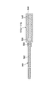
- FIG. 3 is a diagram schematically illustrating configurations of a linear member 50 and a drive unit 40.
- FIG. 3B is a longitudinal sectional view taken along line AA in FIG. 3A. It is a figure which shows the state which the linear member 50 bent.
- FIG. 2 is a diagram schematically showing a schematic configuration of a control system and a charging system including a control unit 70.
- FIG. FIG. 2 is a system diagram of a control unit 100A according to the first embodiment. It is a figure which shows the process of producing
- FIG. 10 is a system diagram schematically illustrating signal processing of a control unit 100B according to the second embodiment.
- FIG. 3 is a diagram schematically showing each task and each phase stored in a database 300. It is a figure which shows typically the process which the wearer is going to perform by comparing a physical quantity with a reference
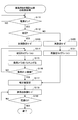
- 10 is a flowchart illustrating a first part of an example of a control process executed by a control unit 100B according to the second embodiment. It is a flowchart which shows the 2nd part of an example of the control processing which the control part 100B of Example 2 performs.
- FIG. 10 is a flowchart illustrating a first part of an example of a control process executed by a control unit 100B according to the second embodiment. It is a flowchart which shows the 2nd part of an example of the control processing which the control part 100B of Example 2 performs.
- FIG. 10 is a system diagram schematically illustrating signal processing of a control system of a control unit 100C according to the third embodiment.
- 12 is a flowchart illustrating a first part of an example of a control process executed by a control unit 100C according to the third embodiment. It is a flowchart which shows the 2nd part of an example of the control processing which 100C of Example 3 performs.
- FIG. 10 is a system diagram schematically illustrating signal processing of a control system of a control unit 100D according to a fourth embodiment.
- 14 is a flowchart illustrating a first part of an example of a control process executed by a control unit 100D according to the fourth embodiment.
- FIG. 10 is a system diagram schematically illustrating signal processing of a control system of a control unit 100E according to a fifth embodiment.
- 14 is a flowchart for explaining a first part of an example of a control process executed by a control unit 100E according to the fifth embodiment.
- It is a flowchart for demonstrating the procedure of the 2nd part of an example of the control processing which the control part 100E of Example 5 performs.
- FIG. 10 is a system diagram schematically illustrating signal processing of a control system of a control unit 100F according to a sixth embodiment.
- 16 is a flowchart for explaining a procedure of control processing executed by a control unit 100F according to the sixth embodiment. It is a flowchart which shows the control procedure of the first calibration which performs initial setting. It is a flowchart which shows the control procedure of the reset calibration by one motion (one operation
- FIG. 3 is a cross-sectional view showing an internal structure of an actuator 510.
- FIG. FIG. 25B is a longitudinal sectional view taken along line DD in FIG. 25A. It is a perspective view which shows the mounting
- FIG. It is the external view which looked at the mounting
- FIG. It is the external view which looked at the mounting
- FIG. It is an external view which shows the operation state which hold
- FIG. It is a figure which shows a part of finger insertion part of mounting
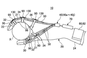
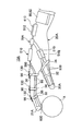
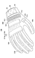
- FIG. 1 is a plan view showing Embodiment 1 of a wearable movement assist device according to the present invention.
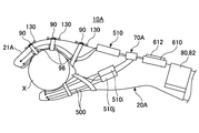
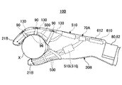
- FIG. 2A is an external view of the wearing-type motion assisting device 10 according to the first embodiment when viewed from the side.
- FIG. 2B is an external view illustrating an operation state in which the object X is gripped by using the wearable movement assist device 10 according to the first embodiment.
- the wearable movement assist device 10 includes a movement assist glove 20 having a finger insertion portion 21 into which each wearer's finger is inserted, and is worn in the same manner as a normal glove.
- the motion assisting glove 20 is provided with a driven unit 30, a driving unit 40 (40a to 40j), a linear member 50 (50a to 50j), a biological signal detection unit 60, and a control unit 70. .
- the wearable motion assisting device 10 is provided with each finger of the motion assisting glove 20 according to the biological signal detected by the biological signal detecting unit 60. Since the insertion portion 21 is driven, each finger can be assisted by a control signal from the control unit 70 to move in the extending direction or the bending direction.
- the wearable motion assist device 10 can also be used for rehabilitation (function recovery training) for performing hand finger motion training.
- the motion assisting glove 20 is formed in a three-dimensional shape according to the size of the hand so as to be in close contact with the wearer's hand.
- the motion assisting glove 20 has a double structure in which the outer motion assisting glove and the inner motion assisting glove are sewn together.
- the outer motion assisting glove has flexibility and durability such as cowhide or synthetic leather. It is formed of a thin rubber material so that the inner motion assisting glove is in close contact with the surface (skin) of the hand.
- an opening 22 for exposing the wearer's fingertip is provided in the fingertip portion of each finger insertion portion 21 of the motion assisting glove 20. As shown in FIG. 2A, the wearer can directly touch an object that grips the skin of the fingertip, and thus can recognize the object X that is gripped by the touch of the fingertip.
- a plurality of linear members 50 (50a to 50j) are arranged along the extending direction of each finger insertion portion 21 on the back side of the movement assisting glove 20.
- One end of each of the plurality of linear members 50 is connected to a driven portion 30 provided at the tip of each finger insertion portion 21 of the motion assisting glove 20.
- the plurality of linear members 50 are members that transmit driving force, but are significantly lighter than metal members and the like, and can reduce the burden on the wearer.
- the driven part 30 is formed in a ring shape, and is arranged outside the opening 22 so as to be in close contact with the outer periphery of the tip of each finger insertion part 21. Further, the plurality of linear members 50 are fastened to the outside of each finger insertion portion 21 of the motion assisting glove 20 by fastening rings 32, 34, 36 wound around the finger joints.
- the fastening rings 32, 34, 36 hold an angle sensor 96 that detects the angle of each finger joint.
- the angle sensor 96 outputs a detection signal corresponding to the angle change to the control unit 70 when the angle of each finger joint changes.
- the plurality of linear members 50 are stitched to the outside of each finger insertion portion 21 of the operation assisting glove 20 or the inside of the outer operation assisting glove. Therefore, the plurality of linear members 50 operate in the extending direction or the bending direction, and each finger of the operation assisting glove 20 also operates in the extending direction or the bending direction integrally with the linear member 50.
- a biasing member 90 is provided at a portion of each finger insertion portion 21 located outside each finger joint.
- the urging member 90 is made of, for example, an elastic member such as a coil spring or rubber material, and one end is connected to the wrist side with respect to the finger joint and the other end is connected to the fingertip side with respect to the finger joint. Therefore, the urging force of the urging member 90 that tries to extend the finger insertion portion 21 is applied to the surface covering the finger joint of each finger insertion portion 21 of the motion assisting glove 20, and the urging force is applied to each finger joint. Acts as an auxiliary force for the extension operation (operation from the gripping state shown in FIG. 2B to the open state shown in FIG. 2A).
- the biasing member 90 may be attached so as to bias each finger joint in a bending direction.
- the urging member 90 is disposed on the palm side, so, for example, the rubber material is processed into a flat shape so that the touch of the object in contact with the palm side is transmitted. It is desirable to use an elastic member.
- a stress sensor 130 is provided at the connecting portion of the biasing member 90.
- the stress sensor 130 includes, for example, a strain gauge, and outputs a detection signal corresponding to a change in stress when the biasing member 90 expands and contracts according to the operation of the finger joint to the control unit 70.
- the driving unit 40 is disposed on the back side of the operation assisting glove 20 and is a driving unit that extends or bends the linear member 50 in the operation direction of the finger joint.
- the driving unit 40 is provided inside the linear member 50.
- Drive mechanisms 40a to 40j for moving the inserted wire in the extending direction or the bending direction are provided.
- two linear members 50a to 50j are arranged on the back side or both sides of each finger insertion portion 21, and a pair of drive mechanisms 40a to 40j is provided for each finger insertion portion 21. It is provided in parallel.
- the biological signal detection unit 60 includes a plurality of bioelectric potential sensors 61 to 65 and is arranged inside the wrist portion 24 of the operation assisting glove 20.
- the bioelectric potential sensors 61 to 65 are electrodes that detect biological signals (for example, myoelectric potential signals, nerve transmission signals, brain waves, etc.) for operating each finger of each hand.
- belts 80 and 82 are provided on both sides of the wrist portion 24 of the motion assisting glove 20 so as to be wound from the outside and brought into close contact with the wearer's hand.
- the belts 80 and 82 are provided with hook-and-loop fasteners 84 for engaging with each other at the overlapping portions.
- the bioelectric potential sensors 61 to 65 are attached to the wearer with the surface fasteners 84 of the belts 80 and 82 facing each other. Can be in close contact with the skin.
- the bioelectric potential sensors 61 to 65 detect a biological signal when the wearer tries to move a finger, and output a detection signal corresponding to the biological signal.
- the control unit 70 performs arithmetic processing (details will be described later) based on the biological signals detected by the biological potential sensors 61 to 65 of the biological signal detection unit 60, and outputs drive control signals to the drive mechanisms 40a to 40j.
- the control unit 70 includes a control unit that performs arithmetic processing, a memory, and a rechargeable battery as will be described later.
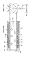
- FIG. 3A is a diagram schematically illustrating the configuration of the linear member 50 and the drive unit 40.
- the linear member 50 includes a cylindrical body 51, wires 52 and 53, and a cap 54.
- the cylindrical body 51 is formed into a cylindrical shape from a flexible resin material. Further, the cylindrical body 51 has a bellows shape in which a hollow portion 55 into which the wires 52 and 53 are inserted is formed on the inner side, and a concave portion and a convex portion that are expanded and contracted in response to an extending operation or a bending operation are alternately arranged on the outer side.
- a portion 56 is formed.
- the opening communicated with the hollow portion 55 at the tip of the cylindrical body 51 is closed by a cap 54.
- the cap 54 is formed of a metal material, and one end of each of the wires 52 and 53 is inserted into the wall portion 54a and integrally joined by welding. Further, the peripheral edge 54 b of the cap 54 is bonded or welded to the end of the cylindrical body 51 and integrated.
- FIG. 3B is a longitudinal sectional view taken along line AA in FIG. 3A.
- the cross-sectional shape of the cylindrical body 51 is a rectangular rectangle, and an upper space 57, a lower space 58, and a plurality of horizontal members 55a horizontally mounted on the hollow portion 55, It is partitioned into a middle space 59.
- wires 52 are mounted in the upper space 57, and in the lower space 58, two wires 53 are mounted.
- a total of four wires 52 and 53 are arranged so as to be vertically symmetrical with respect to the cylindrical body 51.
- the external shape of the cylindrical body 51 is a quadrangle, it is possible to position the lower body in accordance with the operation direction by bringing the lower surface into contact with the outer surface of the operation assisting glove 20.
- the other ends of the wires 52 and 53 are connected to the rotating member 42 of the drive unit 40.
- the rotating member 42 of the present embodiment is formed in an elliptical shape, and the other ends of the wires 52 and 53 are connected to the farthest positions on the peripheral edge of the long diameter portion. Since the two wires 52 and 53 arranged in two are connected to both surfaces of one rotating member 42, they operate simultaneously according to the rotating angle of the rotating member 42. Further, the shaft passing through the central portion of the rotating member 42 is connected to the output shaft of the electric motor 44.
- the drive unit 40 is rotated so as to switch the rotation direction of the rotation member 42, thereby moving the wire 52 and the wire 53 in the opposite directions to thereby apply the driving force to each finger of the operation assisting glove 20. It is possible to efficiently transmit to the unit 21.
- the one on which the tensile force acts operates as a transmission member that transmits the driving force that operates the finger insertion portion 21.
- a torque sensor 94 that detects motor torque is provided at the other end of the output shaft of the motor 44.
- the rotating member 42 rotates clockwise (B direction)
- the upper wire 52 operates in the pulling direction and the lower wire 53 operates in the returning direction.
- the linear member 50 operates so that the cylindrical body 51 returns to a linear shape. Therefore, the extending operation of the linear member 50 is transmitted to each finger insertion portion 21 of the operation assisting glove 20, and can be operated in a state where each finger of the wearer is opened (see FIGS. 1 and 2A).
- the stroke (operation distance) when driving the wires 52 and 53 in the extending direction or the bending direction is determined by the major axis dimension of the rotating member 42 formed in an elliptical shape. It is also possible to increase the stroke from the bending operation to the extending operation of the linear member 50 by increasing the major axis dimension of the linear member 50. Further, instead of the rotating member 42, a gear mechanism and a driving mechanism such as a pulley for winding the wires 52 and 53 may be provided, and the operation stroke of the linear member 50 may be appropriately adjusted by adjusting the rotation amount of the pulley. Is possible.
- the wearable movement assisting device 10 extends or bends the linear member 50 in the direction of movement of the joint of the finger insertion unit 21 based on the drive control signal from the control unit 70, thereby Since the driving force of the driving unit 40 can be transmitted so as to operate the joint, the weight can be reduced and the burden on the wearer can be reduced.
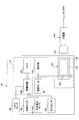
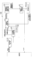
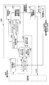
- FIG. 4 is a diagram schematically showing a schematic configuration of a control system including the control unit 70 and a charging system.
- the control unit 70 includes a control unit 100, a memory 102, a display 104, and a rechargeable battery 124.
- the control unit 100 includes a biological signal detected by the bioelectric potential sensors 61 to 65, a torque detection signal of the electric motor 44 detected by the torque sensor 94, and an angle detection signal of each finger joint detected by the angle sensor 96, And a stress detection signal detected by the stress sensor 130 is input.
- the control unit 100 reads each control program and each parameter stored in the memory 102 and performs arithmetic processing based on detection signals from the torque sensor 94, the angle sensor 96, and the stress sensor 130 to operate the auxiliary assisting glove 20.
- the status is displayed on the display unit 104.
- the rechargeable battery 124 is connected to the secondary coil 126 of the charging unit 122 and is periodically charged by the charger 140.
- the charger 140 has a primary coil 142 that generates an electromagnetic induction current in the secondary coil 126. Therefore, a secondary current is generated in the secondary coil 126 of the charging unit 122 by electromagnetic induction by bringing the primary coil 142 close to the operation assisting glove 20. Thereby, the rechargeable battery 124 of the operation assisting glove 20 can be charged while being worn, and can be charged even if the wearer is using it.
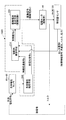
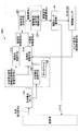
- FIG. 5 is a system diagram of the control unit 100 according to the first embodiment.
- the control unit 100 ⁇ / b> A is an example of the control unit 100 shown in FIG. 4, and includes a computer that executes each control process described later by reading a control program from the memory 102.
- the control unit 100A includes a biopotential processing means (biological signal processing means) 200 that acquires a command signal from the biopotentials detected by the biopotential sensors 61 to 65, a nerve transmission signal b, and a myoelectric potential signal c. And an optional control means 212 for controlling the driving of the electric motor 44 and a drive current generating means 220 for supplying a drive current corresponding to the control signal output from the optional control means 212 to the electric motor 44.
- biopotential processing means biological signal processing means
- the optional control means 212 is a command from the biopotential processing means 200 that generates the nerve transmission signal b and the myoelectric potential signal c from the biopotential signal a generated when each finger is operated by the wearer's intention. Based on the signal, a control signal is output to the drive current generator 220.
- the drive current generation unit 220 generates a drive current according to the control signal from the optional control unit 212 and outputs it to the electric motor 44.
- the biopotential sensors 61 to 65 detect the biopotential signal a generated inside the upper arm and input it to the biopotential processing means 200.
- the biopotential processing means 200 extracts the nerve transmission signal b and the myoelectric potential signal c from the biopotential signal a and inputs them to the optional control means 212.
- the optional control means 212 is based on the nerve transmission signal b and the myoelectric potential signal c obtained from the bioelectric potential signal a generated when each finger of the hand wearing the operation assisting glove 20 is operated at the intention of the wearer.
- An optional control signal d1 is generated.
- the optional control means 212 uses the nerve transmission signal b and the myoelectric potential signal c included in the bioelectric potential signal a, and the optional control signal d1 for causing the electric motor 44 to generate power according to the wearer's intention. Is generated.
- proportional control can be applied.
- the optional control signal d1 and the drive current e are in a proportional relationship.
- the drive current value and the generated torque value of the electric motor 44 are proportional to each other due to the characteristics of the electric motor 44.
- a control law in the optional control means 212 a combination of proportional control, differential control and / or integral control may be applied.
- the biopotential sensors 61 to 65 directly detect the biopotential for operating the finger, and the biopotential a corresponding to the detected biopotential is biopotential processing means. Output to 200.
- the biopotential sensors 61 to 65 detect the biopotential signal a directly from the wrist of the wearer where the wrist portion 24 of the operation assisting glove 22 comes into close contact with the belts 80 and 82, and thus has high detection accuracy. Even weak signals can be accurately detected.
- the optional control means 212 which receives the command signal composed of the nerve transmission signal b and the myoelectric potential signal c from the bioelectric potential processing means 200, generates the control signal d1 from the nerve transmission signal b and the myoelectric potential signal c and generates a drive current. Output to the generation means 220.
- the drive current generation means 220 generates a motor drive current e based on the control signal d from the optional control means 212 and supplies it to the electric motor 44. Thereby, the electric motor 44 rotates the rotating member 42 in the extending direction or the bending direction by supplying the motor driving current e. Therefore, the wires 52 and 53 mounted on the hollow portion 55 of the cylindrical body 51 are moved so that the linear member 50 of the motion assisting glove 20 performs an extending operation or a bending operation.
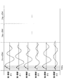
- FIG. 6 is a diagram showing a process of generating each control signal from the biopotential signal.
- the bioelectric potential signal a detected by the bioelectric potential sensors 61 to 65 has a nerve transmission signal b and a myoelectric potential signal c.
- the nerve transmission signal b can be said to be an intention transmission signal, and overlaps the leading region of the myoelectric potential signal. Since the frequency of the nerve transmission signal b is generally higher than the frequency of the myoelectric potential signal c, it can be separated by using different bandpass filters.
- the nerve transmission signal b can be extracted by, for example, the high band-pass filter 204 of 33 Hz to several KHz after the bioelectric potential signal a is amplified by the amplifier 202.
- the myoelectric potential signal c can be taken out by, for example, the 33 Hz to 500 Hz middle band bandpass filter 206 after the bioelectric potential signal a is amplified by the amplifier 202.
- the filters 204 and 206 are connected in parallel.
- both filters 204 and 206 may be connected in series.
- the nerve transmission signal b may overlap not only in the head region of the myoelectric potential signal c but also in the head region and the subsequent regions. In this case, only the head region of the nerve transmission signal b may be used for generating a pulse current described later.
- Smoothing processing (smoothing processing for removing noise) is performed on the nerve transmission signal b and the myoelectric potential signal c.
- Each current is generated by the drive current generation means 220 with a control signal obtained by smoothing the signal from the biological signal processing means 200 as an input.
- the smoothing process alone is pulsed, and the current generated by the drive current generator 220 based on the nerve transmission signal b is also pulsed.
- the current (pulse current) e1 obtained based on the nerve transmission signal b has a rectangular wave shape.
- the myoelectric potential signal c has a wide width on the time axis, it becomes a mountain shape that is substantially proportional to the myoelectric potential by performing the smoothing process, and is generated by the drive current generating means 220 based on the myoelectric potential signal c.
- the current e2 is also mountain-shaped.
- a total current (optional control signal) e of a pulse current e1 generated based on the nerve transmission signal b and a current e2 generated proportionally based on the myoelectric potential signal c is supplied to the electric motor 44.
- the electric motor 44 generates a torque having a magnitude proportional to the total current e.
- the magnitudes of the currents e, e1, e2 input to the electric motor 44 are appropriately set according to the sense of the wearer during operation.
- the electric motor 44 is driven without a delay from the wearer's intention to operate, and the wearer feels uncomfortable about the operation of each finger joint according to his / her intention. It can be carried out.
- the pulse current e1 is shown particularly large, but this is for emphasizing its role, and does not show the relationship between the actual pulse current and the drive current e2 obtained from the myoelectric potential signal.
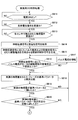
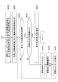
- control unit 100A reads the control program stored in the memory 102 and executes the control process of FIG.
- the nerve transmission signal b and the myoelectric potential signal c are acquired from the biopotential signal a detected by the biopotential sensors 61 to 65 (biopotential processing means). Subsequently, the process proceeds to SA14, where a pulse current e1 is generated based on the nerve transmission signal b, and a current e2 is generated based on the myoelectric potential signal c (drive current generating means).
- next SA15 it is checked whether or not the pulse current e1 corresponding to the nerve transmission signal b is equal to or greater than the lower limit value It of the electric motor 44 startable drive current.
- the process proceeds to SA16 so that the pulse current e1 becomes equal to or greater than the lower limit value It of the drive startable current.
- the pulse current e1 is amplified.
- each linear member 50 of the motion assisting glove 20 performs an extending operation or a bending operation.
- each finger joint is operated in accordance with the operation of each linear member 50 of the operation assisting glove 20, and the sensor signal f of the torque sensor 94, the angle sensor 96, and the stress sensor 130 (physical quantity sensor) is received. Check whether or not.
- the process proceeds to SA20, and it is checked whether or not the detected stress detected by the stress sensor 130 with the operation of each finger joint by the driving force of the electric motor 44 is equal to or less than a preset allowable value.
- the permissible value is selectively set according to the strength of the urging force of the urging member 90.
- SA20 when the detected stress of each finger joint detected by the stress sensor 130 is equal to or smaller than a preset allowable value (in the case of YES), the process proceeds to SA21 and each physical quantity sensor (torque sensor 94, angle sensor 96, The detection value (physical information) of the stress sensor 130) and the bioelectric potential signal are displayed on the display 104. Accordingly, the wearer can recognize the operation state of each finger joint (the driving force and the driving direction by each linear member 50) from the display on the display unit 104.
- a preset allowable value in the case of YES
- SA20 when the detected stress of each finger joint detected by the stress sensor 130 is equal to or larger than a preset allowable value (in the case of YES), the process proceeds to SA22 and the drive current e supplied to the electric motor 44 is set. For example, decrease by 10%. Note that the amount of decrease in the drive current e can be set to an arbitrary value, and can be changed within a range of 1 to 10%, for example.
- the drive current limited as described above is output to the electric motor 44.
- the electric motor 44 is controlled to generate a torque and a rotation angle that are limited so as not to exceed the strength of each finger joint.
- the process proceeds to SA24, and the limited drive current data is displayed on the display unit 104. Thereafter, the process returns to SA19, where it is checked whether the sensor signal f of each physical quantity sensor (torque sensor 94, angle sensor 96, stress sensor 130) has been received in accordance with the operation of each finger joint. Perform processing.
- the driving force of the electric motor 44 is controlled to be less than the allowable value to prevent excessive torque from being transmitted.
- the processing of SA11 to SA24 is repeatedly executed until the power switch of the control unit 70 is turned off. Thereby, the electric motor 44 is drive-controlled to perform an operation according to the wearer's intention.
- FIG. 8 is a system diagram schematically showing signal processing of the control unit 100B of the second embodiment.
- the same parts as those in FIG. 4 of the first embodiment are denoted by the same reference numerals, and the description thereof is omitted.
- control unit 100B in FIG. 8 is an example of the control unit 100 in FIG.
- the database 300 of the control unit 100B obtains the rotation angle and angular velocity of each finger joint of the wearer empirically for all phases of all tasks, and stores those reference parameters (reference rotation angle and angular velocity, etc.). Yes. Then, the optional control means 212 performs tasks from the database 300 based on physical quantities related to the operation of each finger joint of the wearer when performing optional control of the electric motor 44 of the motion assisting glove 20 (see FIGS. 1 to 3). The phase is estimated, and the driving force is generated in the electric motor 44 so that the power assist rate corresponding to the estimated phase is obtained.
- a task is a classification of movement patterns of each finger joint of the wearer, and a phase is a series of minimum movement units constituting each task.
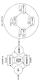
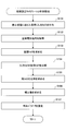
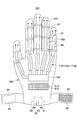
- FIG. 9 is a diagram schematically illustrating as a basic operation of each finger, extending a finger (task A), grasping an object (task B), bending a finger (task C), and shaking hands (task D). .
- the operation assisting glove 20 is mounted on the wearer is described, but here, for convenience of explanation, the operation of each finger is given as an example. I will explain.
- each task consists of the above phases.
- task B for grasping an object includes phase B1 in which each finger is aligned, phase B2 in which the first joint of each finger is bent, and the first, It consists of a phase B3 in which the second joint is bent and a phase B4 in which the first, second and third joints of each finger are bent.
- phase sequence Such a series of phases B1 to B4 is referred to as a phase sequence.
- the appropriate power for assisting the wearer's finger joint movement varies from phase to phase. Therefore, by providing different power assist rates PAR1, PAR2, PAR3, and PAR4 depending on each phase, optimal operation assistance can be performed for each phase.
- the rotation angle and angular velocity, motion speed, acceleration, etc. of each finger joint in each phase are determined. For example, a typical finger movement pattern of the wearer is determined, and it feels most natural when the movement assisting glove 20 is operated with the movement pattern. Therefore, the rotation angle and angular velocity of each finger joint of the wearer are obtained empirically for all phases of all tasks and stored in the database 300 as reference parameters (reference rotation angle and angular velocity, etc.). .
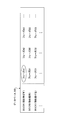
- FIG. 10A is a diagram schematically showing each task and each phase stored in the database 300.
- FIG. 10B is a diagram schematically illustrating a task that a wearer is going to perform by comparing a physical quantity with a reference parameter, and a process for estimating a phase therein.
- the tasks and phases shown in FIGS. 10A and 10B are as shown in FIG.
- the illustrated task A, task B, task C... Is composed of a series of phases (phase A1, phase A2, phase A3..., Phase B1, phase B2, phase B3...), Respectively. Yes.
- the actual values of various physical quantities obtained from the sensor signals detected by the angle sensor 96 and the stress sensor 130 as physical quantity sensors are compared with the reference parameters stored in the database 300. To do.
- the comparison is shown schematically in the graph in FIG. 10B.
- the rotation angle ⁇ 1 and angular velocity ⁇ 1 ′ of the first joint of each finger, the rotation angle ⁇ 2 and angular velocity ⁇ 2 ′ of the second joint of each finger, and the rotation angle ⁇ 3 and angular velocity ⁇ 3 ′ of the third joint of each finger are shown.
- the physical quantities to be compared are not limited to these.
- phase identification may be performed after confirming coincidence in a plurality of times. For example, in the example shown in the figure, if the measured value matches the reference parameter of phase A1 at a plurality of times, it can be seen that the current operation is the operation of phase A1.
- the phase having the reference parameter that matches the actually measured value is not necessarily the first phase (A1, B1, C1, etc.) of the task.
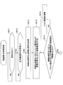
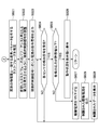
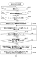
- FIG. 11A and FIG. 11B are flowcharts for explaining a procedure of control processing executed by the control unit 100B of the second embodiment.
- the control unit 100B reads the control program stored in the memory 102 and executes the control processing of FIGS. 11A and 11B.
- SB11, SB12, SB14 to SB17, and SB24 to SB29 are substantially the same as SA11 to SA16 and SA19 to SA24 in FIG.
- the processing of SB13 and SB18 to SB23 will be mainly described.
- SB13 shown in FIG. 11A wireless signals of detection signals of the torque sensor 94, the angle sensor 96, and the stress sensor 130 that detect physical quantities (torque, rotation angle, stress) generated in accordance with the operation of each finger joint are received. Check whether or not. In SB13, when detection signals from the torque sensor 94, the angle sensor 96, and the stress sensor 130 are received, the process proceeds to SB14.
- SB19 it is checked whether the physical quantity (actually measured value) detected by the torque sensor 94, the angle sensor 96, and the stress sensor 130 matches the reference parameter of each phase stored in the database 300. If they do not match, the process returns to SB18, and the processes of SB18 and SB19 are repeated.
- SB19 when the physical quantity (measured value) detected by the torque sensor 94, the angle sensor 96, and the stress sensor 130 matches the reference parameter of each phase stored in the database 300, the process proceeds to SB20, where the sensor It is checked whether or not the number of times the detected physical quantity (actual value) matches the reference parameter of each phase stored in the database 300 has reached a predetermined number of times set in advance.
- SB20 when the number of times of coincidence does not reach the predetermined number set in advance, the process returns to the process of SB18 and the processes of SB18 to SB20 are repeated. If the number of matches in the SB 20 reaches a preset number, the process proceeds to SB 21 in FIG. 11B to select a task and phase corresponding to the reference parameter that matches the measured physical quantity, Is estimated as the selected task and phase.
- the next SB 22 selects the power assist rate assigned to the phase corresponding to the operation to be assisted by referring to the database 300, and the optional SB 22 causes the electric motor 44 to generate power corresponding to the power assist rate. Adjust the control signal (optional control means).
- the wearer's motion and the motion of the joint 20 are estimated based on the physical quantities obtained from the torque sensor 94, the angle sensor 96, and the stress sensor 130, and the estimated
- the electric motor 44 applies power according to the optional control signal, and thus is the same as a normal human finger movement.
- the operation of each finger joint is a smooth operation. Therefore, the wearer can smoothly perform the operation of each finger while wearing the motion assisting gloves 20 (see FIGS. 1 to 3).
- FIG. 12 is a system diagram schematically illustrating signal processing of the control system of the control unit 100C according to the third embodiment.
- the same parts as those in FIGS. 5 and 8 described above are denoted by the same reference numerals, and the description thereof is omitted.
- control unit 100C in FIG. 12 is an example of the control unit 100 in FIG.
- the autonomous control means 310 of the control unit 100C receives the sensor signal f (physical information signal) detected by the torque sensor 94, the angle sensor 96, and the stress sensor 130, the received torque sensor 94, angle sensor 96, By comparing the detected value (physical quantity) of the stress sensor 130 with the reference parameter stored in the database 300, the task and phase of the wearer are estimated, and the electric motor 44 generates a driving force corresponding to the estimated phase.
- An autonomous control signal d2 is generated.
- the control signal combining unit 320 generates a control signal d by combining the optional control signal d1 from the optional control unit 212 and the autonomous control signal d2 from the autonomous control unit 310.
- the autonomous control unit 310 has a torque sensor 94, an angle when the wearer wearing the movement assisting glove 20 (see FIGS. 1 to 3) moves the arm.
- the detected signals of the received torque sensor 94, angle sensor 96, and stress sensor 130 and each task stored in the database 300 are received.
- the task and phase of the wearer are estimated, and an autonomous control signal d2 for generating electric power corresponding to the phase in the electric motor 44 is generated.
- the control signal synthesis unit 320 synthesizes the optional control signal d1 from the optional control unit 212 and the autonomous control signal d2 from the autonomous control unit 310.
- the control signal d synthesized by the control signal synthesizing means 320 is an electric motor that is obtained by adding the power by the optional control that changes from the start to the end of the operation and the power obtained by adding the power by the constant autonomous control for each phase. 44 is generated.
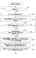
- FIGS. 13A and 13B are flowcharts illustrating a control process executed by the control unit 100C according to the third embodiment.
- the control unit 100C reads the control program stored in the memory 102 and executes the control processes of FIGS. 13A and 13B.
- FIGS. 7A and 7B are substantially the same processing as SB11 to SB13, SB18 to SB20, and SB24 to SB29 in FIGS. 7A and 7B.
- the description is omitted, and here, the processing of SC14, SC18 to SB21 will be mainly described.
- the bioelectric potential signal a detected by the bioelectric potential sensors 61 to 65 is used to generate an optional control signal d1 for causing the electric motor 44 to generate a driving force according to the wearer's intention.
- the optional control signal d1 is used to generate a pulse current corresponding to the nerve transmission signal and a drive current corresponding to the myoelectric potential signal, as in the first and second embodiments.
- the task and phase corresponding to the reference parameter that matches the actual measured value of the physical quantity are selected, the wearer's finger joint motion is estimated as the selected task and phase, and the hybrid ratio ( Voluntary control signal / autonomous control signal). Further, the hybrid ratio is set in advance so as to assist the wearer's operation without a sense of incongruity for each task and phase, and is stored in the database 300. The hybrid ratio is automatically calculated by the control unit 100C as described above when the phase is estimated by comparing the physical quantity actually measured by the torque sensor 94, the angle sensor 96, and the stress sensor 130 with the reference parameter stored in the database 300. Stipulated in
- the total control signal d is generated by synthesizing the optional control signal d1 and the autonomous control signal d2 so that the specified hybrid ratio is obtained (control signal synthesizing means).
- the process proceeds to SC21, and a command signal corresponding to the drive current e generated according to the total control signal d is output.
- the total control signal d is generated to have a required hybrid ratio obtained from the ratio of the voluntary control signal / autonomous control signal. Therefore, the electric motor 44 of the motion assisting glove 20 can generate the driving force according to the optional control signal and the autonomous control signal by being supplied with the driving current e according to the total control signal,
- the movement of the finger joint is as smooth as the normal arm movement. Therefore, the wearer can perform a smooth operation while wearing the operation assisting gloves 20 (see FIGS. 1 to 3).
- FIG. 14 is a system diagram schematically showing the signal processing of the control system of the control unit 100D according to the fourth embodiment.
- the same parts as those in FIGS. 5, 8 and 12 described above are denoted by the same reference numerals, and the description thereof is omitted.
- control unit 100D of FIG. 14 is an example of the control unit 100 of FIG.
- the optional control unit 212 and the autonomous control unit 310 of the control unit 100D compare the detection values (physical quantities) of the torque sensor 94, the angle sensor 96, and the stress sensor 130 with the reference parameters stored in the database 300, Estimate the task and phase of the finger joint movement that the wearer is going to perform, and generate the voluntary control signal d1 and the autonomous control signal d2 so that the hybrid ratio and power assist rate corresponding to the estimated phase are obtained It has the function to do.
- the optional control means 212 includes a control signal for controlling the driving of the electric motor 44 of the auxiliary assisting glove 20 (see FIGS. 1 to 3), a torque sensor 94, an angle based on the nerve transmission signal and the myoelectric potential signal. Control in which tasks and phases are estimated from the database 300 based on physical quantities related to the wearer's motion detected by the sensor 96 and the stress sensor 130, and a driving force is generated in the electric motor 44 so as to achieve a power assist rate corresponding to the estimated phase. Signal.
- 15A and 15B are flowcharts for explaining the procedure of the control process executed by the control unit 100D of the fourth embodiment.
- the control unit 100D reads the control program stored in the memory 102 and executes the control processing of FIGS. 15A and 15B.
- SD11 to SD17 and SD21 to SD27 in FIGS. 15A and 15B are substantially the same as SC11 to SC17 and SC21 to SC27 in FIGS. 13A and 13B.
- the processing of SD20 will be mainly described.
- the task and phase corresponding to the reference parameter that matches the actual measurement value of the physical quantity are selected, and the wearer's motion is estimated as the selected task and phase, and the estimated task and phase are supported.
- a hybrid ratio (optional control signal / autonomous control signal) is defined. Further, by referring to the database 300, the power assist rate assigned to the phase corresponding to the operation to be assisted is defined.
- an autonomous control signal for driving the electric motor 44 with power according to the estimated phase is generated.
- the process proceeds to SD20 in FIG. 15B, and the total control signal d is generated by synthesizing the optional control signal d1 and the autonomous control signal d2 so as to achieve the hybrid ratio and the power assist rate defined as described above.
- the command signal corresponding to the drive current e generated according to the total control signal d obtained by synthesizing the optional control signal d1 and the autonomous control signal d2 so that the specified hybrid ratio and power assist rate are obtained. Is generated.
- the electric motor 44 of the motion assisting glove 20 (see FIGS. 1 to 3) is supplied with a drive current e corresponding to the total control signal so that the hybrid ratio and the power assist rate specified as described above are obtained.
- the electric motor 44 of the motion assisting glove 20 is supplied with a drive current e corresponding to the total control signal so that the hybrid ratio and the power assist rate specified as described above are obtained.
- the operation of each finger joint is as smooth as the normal arm operation. Therefore, the wearer can smoothly operate each of the finger joints while wearing the operation assisting gloves 20 (see FIGS. 1 to 3).
- FIG. 16 is a system diagram schematically showing the signal processing of the control system of the control unit 100E of the fifth embodiment.
- the same parts as those in FIGS. 5, 8, 12, and 14 described above are denoted by the same reference numerals, and the description thereof is omitted.
- Example 5 shown in FIG. 16 is a control system when the bioelectric potential signal a cannot be obtained from the wrist of the wearer, and the operation assisting glove 20 (FIGS. 1 to The driving force of the electric motor 44 shown in FIG. 3 is controlled.
- the operation assistance glove 20 is the same structure as Example 1 mentioned above, the description is abbreviate
- the control unit 100E in FIG. 16 is an example of the control unit 100 in FIG.
- the control unit 100E includes a database 300, an autonomous control unit 310, and a drive current generation unit 220. Since the biopotential signal a cannot be obtained from the wearer, the control unit 100E is not provided with the optional control means 212, and the autonomous control signal d2 generated by the autonomous control means 310 is supplied to the drive current generation means 220. Is done.
- the autonomous control means 310 compares the detected values (physical quantities) of the torque sensor 94, the angle sensor 96, and the stress sensor 130 with the reference parameters stored in the database 300, so that each finger joint that the wearer is going to perform is compared.
- the autonomous control signal d2 is generated so that the hybrid ratio and the power assist rate corresponding to the estimated phase are obtained. Therefore, the drive current generator 220 generates a current corresponding to the autonomous control signal d ⁇ b> 2 and supplies it to the electric motor 44.
- FIGS. 17A and 17B are flowcharts for explaining a procedure of control processing executed by the control unit 100E according to the fifth embodiment.
- the control unit 100E reads the control program stored in the memory 102 and executes the control process of FIG.
- SE11 to SE25 in FIGS. 17A and 17B are processing procedures that substantially exclude SD12 and SD14 in FIGS. 15A and 15B, and are the same processing as SD11, SD12, SD13 to SD17, and AD19 to SD27. These descriptions are omitted. Here, the processing of SE18 will be described.
- the autonomous control signal d2 is generated so that the specified hybrid ratio and power assist rate are obtained. As a result, it becomes possible to cause the electric motor 44 to generate power having a specified hybrid ratio and power assist rate.
- the control unit 100E when the bioelectric potential signal a cannot be obtained from the wearer's wrist, the control unit 100E according to the fifth embodiment performs the operation assisting glove 20 according to the autonomous control signal d2 generated by the autonomous control unit 310. Since the driving force can be obtained from the electric motor 44, the operation of each finger joint is a smooth operation. Therefore, the wearer can smoothly operate each of the finger joints while wearing the operation assisting gloves 20 (see FIGS. 1 to 3).
- FIG. 18 is a system diagram schematically illustrating signal processing of the control system of the control unit 100F according to the sixth embodiment.
- the same parts as those in FIGS. 5, 8, 12, 14, and 16 described above are denoted by the same reference numerals, and the description thereof is omitted.
- the control unit 100F includes a calibration database 400, a phase identification unit 410, a difference derivation unit 420, a parameter correction unit 430, a calibration control unit 440, a load It has the generating means 450.
- the operation assistance glove 20 is the same structure as Example 1 mentioned above, the description is abbreviate
- the control unit 100F in FIG. 18 is an example of the control unit 100 in FIG.
- the calibration database 400 is data storage means for correcting the parameter of the control signal in accordance with the detection sensitivity of the myoelectric potential (bioelectric potential) with respect to the muscle force generated by the wearer.
- the calibration database 400 stores in advance the first correspondence relationship between the muscular strength and the myoelectric potential signal (bioelectric potential signal) generated by the wearer wearing the operation assisting glove 20 (see FIGS. 1 to 3).
- a first storage area, and a second storage area that stores in advance a second correspondence relationship between a muscle force and a myoelectric potential signal (bioelectric potential signal) that are generated along with a change in joint angle in the course of the wearer performing a basic motion of each finger joint;
- the joint angle detected by each physical quantity sensor and the myoelectric potential signals detected by the bioelectric potential sensors 61 to 65 are input to the calibration database 400.
- the calibration control means 440 after the motion assisting glove 20 is attached to the joint 20 of the wearer, based on the biological signal generated in the basic motion of each finger joint by the wearer and the second correspondence relationship, The auxiliary power is corrected by the electric motor 44 (see FIGS. 1 to 3) corresponding to the bioelectric potential signal so as to satisfy the first correspondence relationship.
- the calibration control unit 440 executes the calibration control process when the wearer wears the operation assisting glove 20 and the power switch is turned on, and the load generation unit 450 causes the drive current generation unit 220 to perform calibration control processing.
- the driving force from the electric motor 44 is applied stepwise to each finger joint of the wearer as a load (input torque), and the wearer generates muscle strength of each finger joint so as to antagonize the driving force.
- each finger joint to which the driving force from the electric motor 44 is applied performs a predetermined calibration operation (for example, task A: extend the finger) to generate muscle strength.
- a predetermined calibration operation for example, task A: extend the finger
- the angle sensor 96 detects the joint angle
- the biopotential sensors 61 to 65 detect the myoelectric potential signal of the wrist.
- the phase specifying means 410 specifies the phase of the wearer's calibration operation pattern by comparing the joint angle detected by the angle sensor 96 with the joint angle stored in the calibration database 400.
- the difference deriving unit 420 starts the calibration control process, and the load (input torque) of the electric motor 44 applied by the load generating unit 450 and the myoelectric potential signal of the upper arm detected by the bioelectric potential sensors 61 to 65.
- the muscle strength (estimated torque) corresponding to (actually measured value) is compared, the difference between the two is obtained, and the second correspondence relationship is obtained.
- the first correspondence relationship is based on the difference between the load (input torque) and the muscle strength (estimated torque) calculated by the difference deriving unit 420 in the phase specified by the phase specifying unit 410.
- the parameter K is corrected so as to satisfy When there is no difference between the input torque from the electric motor 44 applied by the load generating means 450 and the muscle force corresponding to the myoelectric potential signals (actual measurement values) detected by the bioelectric potential sensors 61 to 65, the reference parameter is corrected. do not do.
- the parameter K is corrected so as to match.
- the correction parameter K ′ is set so that the input torque and the estimated torque are equal.
- the calibration control means 440 sets the parameter corrected by the parameter correction means 430 as the parameter of the wearer, and performs calibration for the next phase.
- the electric motor 44 is controlled so as to generate the assist force according to the biopotential signal detected by the biopotential sensors 61 to 65 using the parameters set by the calibration. Regardless of the state (skin resistance value, biopotential state, etc.) or the displacement of the attachment positions of the biopotential sensors 61 to 65, it is possible to control the power assist rate to maintain a predetermined value.
- the joint angle detected by the angle sensor 96 and the myoelectric potential signals detected by the bioelectric potential sensors 61 to 65 are supplied to the control unit 100F, and each phase corresponding to the joint angle and the myoelectric potential signal is supplied.
- the driving force from the electric motor 44 is calculated using the correction parameter K ′ set by the calibration control unit 440, and a control signal obtained from the calculation result is supplied to the driving current generation unit 220.
- the calibration control means 440 may execute the calibration control process every time the power switch 150 of the remote controller 40 is turned on, or by providing a dedicated calibration switch 460. The operator may execute the calibration control process by his / her own operation. In addition, by providing the timer switch 470, it is possible to automatically execute the calibration control process at an arbitrary time set in advance (for example, every morning at 8:00 or Monday at 8:00).
- the calibration control process is frequently executed in order to perform power correction in the process of the wearer practicing the operation of the motion assisting gloves 20, but if one week or more has elapsed since the start of practice, It can be switched to run every hour. Therefore, the power switch 150, the calibration switch 460, and the timer switch 470 may be properly used according to the number of times of use (the number of exercises), or the calibration switch 460 or the timer switch 470 may be appropriately operated. .
- the wearer wearing the motion assisting gloves 20 sets a correction value (parameter K ') corresponding to the wearer's muscular strength obtained by the calibration in the stationary state (correction value setting means). That is, in S115, for example, the parameter K is obtained so that the value of the surface myoelectric potential becomes 1 when the wearer gives a force of 1 Nm while standing still with each finger joint extended.
- the driving force (torque ⁇ m) of the electric motor 44 is applied stepwise to each finger joint of the wearer as a load (input torque), whereas the wearer antagonizes the driving force. Generate muscle strength at each finger joint.
- the biopotential signals generated against the driving force applied from the electric motor 44 are detected by the biopotential sensors 61 to 65, and parameters for the arithmetic processing are generated based on the detection signals.
- the correction value unique to the wearer is stored in the calibration database 400.
- the wearer immediately after the movement assisting glove 20 is worn on the wearer, the wearer is able to perform the operation based on the correspondence between the power and the bioelectric potential signal generated in the process in which the wearer performs a predetermined basic operation (calibration operation). It becomes possible to correct the driving force of the electric motor 44 in accordance with the biological signal so as to satisfy the correspondence relationship between the generated power and the biological potential signal.
- the one-motion calibration is performed after the second time.
- the present invention is not limited to this, and the correction value setting calibration may be performed in the still state in the second and subsequent times as in the first time. good.
- FIG. 20 is a flowchart showing a control procedure of initial calibration for performing initial setting.
- the correction value is set by generating a muscle force so that the wearer keeps the joint 20 stationary with respect to the motor load.
- the control unit 100F supplies a predetermined driving current to the electric motor 44 with the driving force (input torque) as a load in step S131 while the wearer keeps each finger joint stationary.
- the wearer generates muscular power so as to antagonize the driving force of the electric motor 44 with each finger joint extended.
- the myoelectric potential signal (bioelectric potential signal) of the wearer's wrist detected by the bioelectric potential sensors 61 to 65 is acquired.
- a virtual torque is estimated by calculation based on the actually measured myoelectric potential signal.
- the process proceeds to S134, and the input torque applied as a load is compared with the virtual torque.
- S135 the ratio between the input torque and the virtual torque is obtained.
- the parameter for the load for each phase stored in the calibration database 400 is read out, and the correction value (correction parameter) of the control signal supplied to the drive current generation means 220 is multiplied by the above ratio. Ask.
- the process proceeds to S137, and the correction parameter is set as a parameter for autonomous control (correction value setting means).
- the wearer with the motion assisting glove 20 attached to the joint 20 can automatically calibrate the biological signal according to the state of the day while still. Therefore, the labor and time required for calibration can be greatly reduced.
- FIG. 21 is a flowchart showing a control procedure of reset calibration by one motion (one operation).
- the wearer moves the finger only once from the stretched state to the bent state.
- the memory 102 stores in advance a reference myoelectric potential corresponding to the calibration operation.
- the control unit 100F confirms the presence or absence of a detection signal from the angle sensor 96 of the joint 20 in S141.
- the angle sensor 96 detects the angular movement of each finger joint as the wearer moves each finger joint, the process proceeds to S142, and the operation of each finger joint is performed based on the detection signal from the angle sensor 96. Set the angle.
- the process proceeds to S143, and the reference myoelectric potential corresponding to the operation angle of each finger joint is read from the memory 102.
- the measured value of the myoelectric potential of the wearer's wrist is read from the bioelectric potential sensors 61-65.
- the reference myoelectric potential is compared with the measured value of the myoelectric potential.
- the correction value is obtained so as to correct the relationship between the reference myoelectric potential and the bioelectric potential signal (myoelectric potential signal) detected via the bioelectric potential sensor in accordance with the change in the joint angle accompanying a predetermined operation.
- the correction value can be set so as to perform control suitable for various joint angle states.
- the parameter K ′ is corrected by an operation (one motion) in which each finger is rotated from a stretched state to a bent state without using the motor driving force as a load. Therefore, it is possible to greatly reduce the physical burden on the wearer and to shorten the preparation time required for calibration after the operation assisting glove 20 is worn. Therefore, in the second and subsequent calibrations, the operation can be started quickly. Furthermore, since calibration can be performed during operation, it is possible to perform calibration frequently by bending each finger joint during normal operation without being particularly conscious of the wearer, which is always optimal. Control can be performed.
- the wearer operates each finger joint in the extending direction or the bending direction and, for example, operates from a state where the finger is extended to a state where the finger is bent.
- the control unit 100F confirms the presence or absence of a detection signal from the angle sensor 96 in S151.
- the process proceeds to S152, and the calibration database 400 is based on the detection signal from the angle sensor 96. Select the task stored in and set the wearer's standard action.
- the reference myoelectric potential corresponding to the operation of each finger joint is read from the memory 102. Subsequently, the process proceeds to S154, and the measured value of the myoelectric potential of the wearer's wrist is read from the bioelectric potential sensors 61-65. In S155, the reference myoelectric potential is compared with the actually measured value of the myoelectric potential.
- step S156 the ratio between the reference myoelectric potential and the measured value of the myoelectric potential is obtained.
- step S157 a parameter corresponding to the operation angle of the joint 20 stored in the calibration database 400 is read, and the correction value of the control signal supplied to the drive current generation unit 220 is multiplied by the above ratio (see FIG. Correction parameter).
- step S158 the process proceeds to S158, in which a correction parameter is set as a parameter for optional control (correction value setting means).
- next S159 it is confirmed whether the calibration operation task is completed.
- the process proceeds to S160 to update to the next phase and execute the processing from S153 onward again.
- the second and subsequent calibrations can correct the parameter K ′ without using the driving force of the electric motor 44 of the motion assisting glove 20, the physical burden on the wearer can be greatly reduced. At the same time, it is possible to reduce the preparation time required for calibration after wearing the motion assisting gloves 20.
- the calibration operation may be performed by combining the operation of each finger joint by the wearer, so that the surface myoelectric potential may be calibrated, or the calibration by the operation suitable for the individual can be performed.
- the wearer is a physically handicapped person, it is possible to perform calibration by an arbitrary operation that can be operated, and other operations (tasks) can be used as a reference operation.
- the configuration in which the calibration control process is added to the control circuit of the first embodiment described above has been described.
- the calibration control process is similarly executed in the other second to fifth embodiments.
- the control process is the same as the control process shown in FIGS. 19 to 22, the description of the calibration control process according to the other embodiments 2 to 5 is omitted. .
- FIG. 23 is a perspective view showing Modification 1 of the wearable motion assisting device 10.
- the wearing-type motion assisting device 10A of Modification 1 includes a motion assisting glove 20A, a plurality of linear members 500, a drive unit 510, a biological signal detection unit 60, and a control unit 70A.
- a rechargeable battery 610 is provided.
- the rechargeable battery 610 has a solar cell 612 on the surface, and is always charged by the solar cell 612 that receives indoor illumination light or sunlight and generates power.
- the motion assisting glove 20A is formed in a three-dimensional shape according to the size of the hand so as to be in close contact with the wearer's hand, like the motion assisting glove 20 of Example 1 described above.
- the motion assisting gloves 20A are provided with finger insertion portions 21A as driven portions into which the wearer's fingers are inserted. As shown in FIG. 24A, an object detection sensor 600 that detects an object X is provided below the tip of the finger insertion portion 21A.
- the object detection sensor 600 is made of a thin and flexible membrane switch or the like, and outputs a detection signal to the control unit 70A when contacting the object X.
- the control unit 70A performs arithmetic processing for generating a driving force so that each finger insertion portion 21A performs a gripping operation.
- an object detection sensor 600 is provided at the tip of each finger insertion portion 21A of the motion assisting glove 20A, and, for example, a push-type microswitch is arranged on a non-gripping portion that does not contact the object X such as the wrist or the side of the hand.
- a push-type microswitch is arranged on a non-gripping portion that does not contact the object X such as the wrist or the side of the hand.
- the linear member 500 can be driven so that each finger insertion portion 21A performs a gripping operation.
- the object detection sensor 600 is not limited to the membrane switch and the micro switch.
- the reflection type optical sensor or proximity sensor inductive proximity sensor
- Capacitance type proximity sensor, magnetic type proximity sensor may be used.
- a plurality of linear members 500 are arranged along the extending direction of each finger insertion portion 21A on the back side of the motion assisting glove 20A and on both sides of each finger insertion portion 21A.
- One end of each of the plurality of linear members 500 is connected to each finger insertion portion 21A of the motion assisting gloves 20A.
- the four linear members 500 are arranged in one finger insertion portion 21A.
- the number of the linear members 500 can be appropriately increased or decreased according to the above.
- the finger insertion part 21A is formed integrally with the motion assisting gloves 20A, and is formed in a cap shape so as to cover the entire fingers.
- the plurality of linear members 500 are fastened to the outside of the motion assisting gloves 20A by fastening rings 32, 34, and 36 wound around the finger joints. Therefore, the drive part 510 can transmit a driving force to each finger
- the linear member 500 of the first modification example is formed of a hollow resin tube (cylindrical body), and a hollow system path filled with a fluid is formed extending in the longitudinal direction.
- the some linear member 500 is a member which transmits a driving force, compared with a metal member etc., it is reduced in weight significantly and can also reduce a burden of a wearer.
- the aforementioned urging member 90 is provided outside the joint portion of each finger insertion portion 21A. Therefore, the urging force of the urging member 90 that attempts to extend each finger insertion portion 21A is applied to the surface of the finger insertion portion 21A that covers the finger joint of the motion assisting glove 20A, and the urging force is applied to each finger joint. Acts as an auxiliary force for the extension operation (operation from the gripping state shown in FIG. 24B to the open state shown in FIG. 24A).
- the drive unit 510 includes actuators 510a to 510j that pressurize or depressurize the fluid 520 (shown in a satin pattern) filled in the hollow path 502 of the linear member 500.
- the actuators 510 a to 510 j each have a pair of Peltier elements 540 housed inside a flat housing 530.
- the Peltier element 540 is a temperature adjusting unit that adjusts the temperature of the fluid 520 by performing heating by heat generation or cooling by heat absorption according to the direction of current flow.
- the fluid 520 is made of a gel having such a property that the volume decreases at a high temperature and the volume increases at a low temperature.
- the gel used for the fluid 520 includes, for example, a polymer called polybenzyl methacrylate having a property of increasing the volume 10 times by entering a liquid into a three-dimensional network structure of the polymer, and an imidazolium-based ion. Formed from liquid.
- the fluid 520 Since the fluid 520 is heated or cooled simultaneously from above and below in the gap between the pair of Peltier elements 540, the fluid 520 is filled in the housing 530 so that the volume can be reduced or increased in a short time.
- the actuators 510a to 510j are heated or cooled by the pair of Peltier elements 540 in a state where the fluid 520 is filled in the flat space, the hollow path of the linear member 500 connected to the outlet 550 A pressure (reduced pressure or increased pressure) corresponding to the volume change is applied to the fluid 520 at 502.
- each linear member 500 is formed of a resin thin tube having a hollow channel 502 therein, and the inside and outside of the resin thin tube have a bellows shape (bellows shape) as shown in FIG. 3A described above. ). Therefore, each linear member 500 is provided so that it can expand and contract in the longitudinal direction (axial direction) in accordance with the increase or decrease of the pressure of the fluid 520 filled in the hollow path 502.
- Each linear member 500 is fastened to the outside of the motion assisting glove 20A by fastening rings 32, 34, and 36.
- Each linear member 500 has a driving force to extend each finger insertion portion 21A when the back side of the operation assisting glove 20A is depressurized and contracted in the longitudinal direction, and when the palm side of the operation assisting glove 20A is pressurized and extended in the longitudinal direction. Is given to each finger insertion portion 21A. Further, each linear member 500 bends each finger insertion portion 21A portion when the back side of the motion assisting glove 20A is pressurized and extends in the longitudinal direction, and when the palm side of the motion assisting glove 20A is decompressed and contracted in the longitudinal direction. A driving force is applied to.
- a resin material having heat resistance that maintains a state in which the hollow channel 502 in which the fluid 520 that changes from a low temperature to a high temperature is sealed is used. Further, the electric power charged in the rechargeable battery 610 is supplied to each Peltier element 540 of the actuators 510a to 510j. The rechargeable battery 610 is always charged by the solar battery 612 in order to cover the power consumption of each Peltier element 540.
- each linear member 500 is arranged on one side of each finger insertion portion 21A, and actuators 510a to 510j are provided in parallel for each finger insertion portion 21A. That is, four linear members 500 are arranged on both sides of one finger insertion portion 21A, and are connected to different drive portions on the palm side and the back side of the hand. Therefore, each linear member 500 can be driven in a state in which each finger insertion portion 21A is extended by, for example, pressurizing the palm side and decompressing the back side of the hand. Conversely, by depressurizing the palm side of each linear member 500 and pressurizing the back side of each hand, each finger insertion portion 21A can be driven into a gripping state.
- the control unit 70A performs arithmetic processing based on the biological signals detected by the biological potential sensors 61 to 65 of the biological signal detector 60, and outputs drive control signals to the actuators 510a to 510j. Since the control process in the control unit 70A is performed in the same manner as the control process executed by the control units 100 and 100A to 100F of the first to sixth embodiments, description of the control process is omitted here.
- the linear member 500 is moved along the direction of motion of the joint of the finger insertion portion 21A based on the drive control signal from the control unit 70A as in the first embodiment. Since the driving force of the driving unit 510 can be transmitted so as to operate the joints of the wearer's fingers by extending or bending the head, the weight can be reduced and the burden on the wearer can be reduced. Is possible.
- the temperature adjusting means for adjusting the temperature of the fluid 520 is not limited to the Peltier element described above, and for example, a heating wire may be disposed in the hollow path 502 and heated by energization. According to such a configuration, since the fluid 520 in the hollow path 502 can be heated as a whole, the temperature can be quickly changed, and the responsiveness of the drive unit 510 is improved. The fluid 520 is cooled sufficiently quickly by heat radiation from the surface of the hollow path 502 because the hollow path 502 is formed in a thin line shape.
- the fluid 520 may be a gel mixed with a fibrous conductor.
- the fibrous conductor moves and aligns in the gel due to Coulomb force, and forms a conductive path.
- the gel itself has the property of causing a volume change as the internal temperature changes.
- a voltage application electrode is arranged instead of the Peltier element at the position where the pair of Peltier elements 540 is arranged, and the gel between the electrodes is arranged.
- the driver 510 can be driven by applying an electric field.
- FIG. 26 is a perspective view showing a wearable motion assisting device 10B of Modification 2. In FIG. 26, the same portions as those in FIG.
- the wearable motion assisting device 10B includes a motion assisting glove 20B, the plurality of linear members 500 of the first modification, the drive unit 510, the biological signal detection unit 60, and the control unit 70A.
- the drive part 510 can transmit a driving force to each finger
- the rechargeable battery 610 has the solar cell 612 on the surface, the solar cell 612 is provided so as to be exposed from the outer glove of the operation assisting glove 20B.
- the motion assisting glove 20B is not normally visible because the plurality of linear members 500, the drive unit 510, the biological signal detection unit 60, and the control unit 70A are hidden from view. It can be designed like a glove. Therefore, even when the wearer goes out with wearing the motion assisting gloves 20C, the finger joint can be operated without worrying about the eyes of a third party.
- the plurality of linear members 500, the drive unit 510, the biological signal detection unit 60, and the control unit 70A are arranged inside the outer motion assisting glove, and the plurality of linear members 500 and the drive unit 510 are arranged.
- a cover member made of cloth, leather, or synthetic leather may be partially stitched to at least a portion that comes into contact with the biological signal detection unit 60 and the control unit 70A by inserting a finger.
- FIG. 28 is a perspective view showing a wearable motion assisting device 10C of Modification 3.
- the wearing-type operation assisting device 10C includes an operation assisting glove 20C, a plurality of linear members 700, a drive unit 710, a biological signal detection unit 60, a control unit 70C, and a rechargeable battery. 610 is provided.
- the plurality of linear members 700 are wires such as piano wires, for example.
- the drive unit 710 includes linear motors 710a to 710j.
- the plurality of linear members 700 are members that transmit driving force, but are significantly lighter than rod-like metal members and the like, and can reduce the burden on the wearer.
- a linear member 700 is connected to the movers (magnets) of the linear motors 710a to 710j.
- the other end of the linear member 700 is connected to the finger insertion portion 21C of the motion assisting glove 20C.
- the motion assisting gloves 20C are provided with a linear scale for measuring the moving amount of the mover of the linear motors 710a to 710j.
- the attachment position of the linear scale for example, it may be provided so as to measure the moving amount of the movable element, or may be arranged along the linear member 700 connected to the movable element.
- the plurality of linear members 700 are stitched to the outside of the motion assisting gloves 20C. Therefore, the plurality of linear members 700 operate in the extending direction or the bending direction, and each finger insertion portion 21C of the operation assisting glove 20C also operates in the extending direction or the bending direction integrally with the linear member 700. Therefore, the driving unit 710 can efficiently transmit the driving force of the linear motors 710a to 710j to each finger insertion unit 21C of the motion assisting glove 20C via each linear member 700.
- the linear motors 710a to 710j are energized by energizing a plurality of coils constituting the stator by a control signal from the control unit 70C, and generate thrust for the mover. As shown in FIGS. 29A and 29B, the plurality of linear members 700 extending along the finger insertion portions 21C of the motion assisting gloves 20C are stretched or bent by the thrust of the linear motors 710a to 710j. Driven directly to.
- the control unit 70C of the third modification performs arithmetic processing (details will be described later) based on the biological signals detected by the bioelectric potential sensors 61 to 65 of the biological signal detector 60, as in the case of the above embodiments.
- the drive control signal is output to the linear motors 710a to 710j. Since the control processing in the control unit 70C is performed in the same manner as the control processing executed by the control units 100 and 100A to 100F of the first to sixth embodiments, description of the control processing is omitted here.
- FIG. 30 is a perspective view showing a wearable motion assisting device 10D of Modification 4. As shown in FIG.
- the wearing-type operation assisting device 10D includes an operation assisting glove 20D, a plurality of linear members 800, an applied voltage switching circuit 810, a biological signal detection unit 60, a control unit 70D, and a charging unit.
- a battery 610 is provided.
- Each linear member 800 is fastened to each finger insertion portion 21D by fastening rings 32, 34, and 36. Therefore, the driving force generated in the linear member 800 is directly transmitted to each finger insertion portion 21D, and each finger insertion portion 21D is in a straight state (a state in which each finger is extended) or a bent state (a finger is bent). Act to drive).
- the plurality of linear members 800 are made of, for example, a flexible synthetic resin substrate that generates a driving force by generating a volume change depending on the magnitude of the applied voltage or the sign of the applied voltage. That is, each linear member 800 drives each finger insertion portion 21D from a linear state to a bent state, or drives from a bent state to a linear state in accordance with the voltage applied to the electrode layer by the applied voltage switching circuit 810. Generate driving force.
- each linear member 800 is a driving unit that generates a driving force itself, an actuator composed of another motor or the like is not necessary, and is significantly lighter than that provided separately by the actuator. The burden on the user can be reduced.
- FIG. 29 of this modification 4 although the example of a structure which has arrange
- FIG. 31A is a view showing a part of the finger insertion portion of the wearing-type motion assisting device 10D of Modification 4 in cross section.
- FIG. 31B is a diagram illustrating an operation state in which the finger insertion portion of the wearing-type motion assisting device 10D of Modification 4 is bent.
- a linear member 800 extends in the finger extending direction of each finger insertion portion 21D on the front side (palm side) and back side (back side of the hand) of each finger insertion portion 21D of the motion assisting glove 20D. It is attached to exist.
- the electrode layers 801 and 802 of each linear member 800 are connected to output terminals of an applied voltage switching circuit 810 (810a to 810j) via voltage control wires 804, respectively.
- the applied voltage switching circuit 810 (810a to 810j) is connected to the rechargeable battery 610 as a voltage supply source, and is a voltage applied to the electrode layers 801 and 802 of each linear member 800 by a control signal from the control unit 70D. Control the polarity and voltage magnitude.
- the linear member 800 is arranged in parallel and is laminated so that the drive layer 803 is interposed between the pair of electrode layers 801 and 802.
- the drive layer 803 is made of, for example, an ion exchange resin whose driving force generation direction is switched depending on the polarity (positive or negative) of the applied voltage.
- the ion conduction actuator formed by laminating electrode layers 801 and 802 on the upper and lower surfaces of this ion exchange resin is in a stationary state (non-driving state) extending linearly when no voltage is applied.
- the positive side (anode side) cation in the polymer electrolyte moves to the negative side (cathode side) by switching between the positive and negative of the pair of electrode layers 801 and 802, so that Due to the positive and negative of the exchange resin, a difference in swelling occurs and the negative resin (cathode side) warps.
- the drive layer 803 causes the force generated by the difference in swelling between the front and back sides to act as a drive force that operates each finger insertion portion 21D.
- the direction of deformation of the drive layer 803 can be switched by switching the polarity of the pair of electrode layers 801 and 802 to positive or negative by the applied voltage switching circuit 810, and the amount of deformation is controlled by the magnitude of the applied voltage. It becomes possible.
- the polarity of the applied voltage is changed so that the upper electrode layer 801 is negative (cathode) and the lower electrode layer 802 is positive (anode).
- the upper swelling becomes larger than the lower side, so that a driving force Fa is generated to bend each finger insertion portion 21D downward.
- each finger insertion portion 21D is driven in the bending direction and operates from a straight state XA indicated by a broken line to a bent state XB in which each finger joint is bent. Moreover, when the voltage to the electrode layers 801 and 802 of each linear member 800 is turned off (zero), each finger insertion portion 21D is driven in the extending direction, and slowly changes from the bent state XB indicated by the solid line to the linear state XA. Return at speed.
- the polarity of the applied voltage is set so that the upper electrode layer 801 is positive (anode) and the lower electrode layer 802 is negative (cathode) among the electrode layers 801 and 802 of each linear member 800.
- a driving force Fb that tries to warp each finger insertion portion 21D upward is generated.
- each finger insertion portion 21D can be quickly returned from the bent state XB indicated by the solid line to the linear state XA.
- This return operation speed is effective when performing rehabilitation, and can apply a large torque to the finger in a direction in which the finger is extended from a bent state.
- the voltage applied to the electrode layers 801 and 802 of the respective linear members 800 is determined by the drive control signal from the control unit 70D as in the first embodiment.
- the polarity By switching the polarity, it becomes possible to generate the driving forces Fa and Fb in the direction in which each finger insertion portion 21D is extended or bent, so that the weight can be reduced and the burden on the wearer can be reduced. It becomes possible.
- the drive layer 803 is not limited to an ion exchange resin, and for example, a polymer material such as a piezoelectric polymer, a conductive polymer, or an electrostrictive polymer that generates deformation or displacement due to volume expansion when a voltage is applied thereto is used. Of course it is good.
- the fingertip portions of the motion assisting gloves 20A to 20D may be cut in the same manner as the motion assisting gloves 20 of the first embodiment so that the wearer's fingertips are exposed.
Landscapes
- Health & Medical Sciences (AREA)
- Life Sciences & Earth Sciences (AREA)
- Animal Behavior & Ethology (AREA)
- Veterinary Medicine (AREA)
- Public Health (AREA)
- General Health & Medical Sciences (AREA)
- Heart & Thoracic Surgery (AREA)
- Engineering & Computer Science (AREA)
- Biomedical Technology (AREA)
- Physics & Mathematics (AREA)
- Surgery (AREA)
- Molecular Biology (AREA)
- Medical Informatics (AREA)
- Pathology (AREA)
- Biophysics (AREA)
- Orthopedic Medicine & Surgery (AREA)
- Oral & Maxillofacial Surgery (AREA)
- Vascular Medicine (AREA)
- Physical Education & Sports Medicine (AREA)
- Epidemiology (AREA)
- Pain & Pain Management (AREA)
- Rehabilitation Therapy (AREA)
- Transplantation (AREA)
- Cardiology (AREA)
- Dentistry (AREA)
- Physiology (AREA)
- Geometry (AREA)
- Nursing (AREA)
- Prostheses (AREA)
- Manipulator (AREA)
- Rehabilitation Tools (AREA)
Abstract
Description
20、20A~20D 動作補助手袋
21、21A~21D 指挿入部
22 開口
24 手首部
30 被駆動部
32、34、36 締結リング
40、510、710 駆動部
40a~40j 駆動機構
42 回動部材
44 電動モータ
50、50a~50j、500、700、800 線状部材
51 筒状体
52、53 ワイヤ
54 キャップ
55 中空部
57 上部空間
58 下部空間
59 中部空間
60 生体信号検出部
61~65 生体電位センサ
70、70A、70C、70D 制御ユニット
80、82 ベルト
84 面ファスナ
90 付勢部材
94 トルクセンサ
96 角度センサ
100、100A~100F 制御部
102 メモリ
104 表示器
124、610 充電式バッテリ
130 応力センサ
140 充電器
200 生体電位処理手段(生体信号処理手段)
202 増幅器
204 高帯域バンドパスフィルタ
206 中帯域バンドパスフィルタ
212 随意的制御手段
220 駆動電流生成手段
300 データベース
310 自律的制御手段
320 制御信号合成手段
400 キャリブレーションデータベース
410 フェーズ特定手段
420 差分導出手段
430 パラメータ補正手段
440 キャリブレーション制御手段
450 負荷発生手段
502 中空系路
510a~510j アクチュエータ
520 流動体
530 ハウジング
540 ペルチェ素子
612 太陽電池
600 物体検出センサ
710a~710j リニアモータ
810 印加電圧切替回路
801,802 電極層
803 駆動層
図20は初期設定を行う初回キャリブレーションの制御手順を示すフローチャートである。尚、初回キャリブレーションの場合、前述したように、装着者がモータ負荷に対して関節20の静止状態を保つように筋力を発生させることにより補正値を設定する。
(変形例1)
図23は装着式動作補助装置10の変形例1を示す斜視図である。尚、図23において、前述した図1と同じ部分については、同一符合を付してその説明を省略する。図23に示されるように、変形例1の装着式動作補助装置10Aは、動作補助手袋20Aと、複数の線状部材500と、駆動部510と、生体信号検出部60と、制御ユニット70Aと、充電式バッテリ610が設けられている。充電式バッテリ610は、表面に太陽電池612が配されており、室内の照明光または太陽光を受光して発電を行なう太陽電池612により常時充電されている。
(変形例2)
図26は変形例2の装着式動作補助装置10Bを示す斜視図である。尚、図26において、前述した図23と同じ部分については、同一符合を付してその説明を省略する。図26に示されるように、装着式動作補助装置10Bは、動作補助手袋20Bと、上記変形例1の複数の線状部材500と、駆動部510と、生体信号検出部60と、制御ユニット70Aとが外側動作補助手袋と内側動作補助手袋との間に収容されている。そのため、駆動部510は、各線状部材500を介して駆動力を動作補助手袋20Bの各指挿入部21Bに効率良く伝達することができる。
(変形例3)
図28は変形例3の装着式動作補助装置10Cを示す斜視図である。尚、図28において、前述した図23と同じ部分については、同一符合を付してその説明を省略する。図28に示されるように、装着式動作補助装置10Cは、動作補助手袋20Cと、複数の線状部材700と、駆動部710と、生体信号検出部60と、制御ユニット70Cと、充電式バッテリ610が設けられている。
(変形例4)
図30は変形例4の装着式動作補助装置10Dを示す斜視図である。図30に示されるように、装着式動作補助装置10Dは、動作補助手袋20Dと、複数の線状部材800と、印加電圧切替回路810と、生体信号検出部60と、制御ユニット70Dと、充電式バッテリ610が設けられている。
Claims (20)
- 装着者の指が挿入される指挿入部を有する動作補助手袋と、
前記動作補助手袋の甲側に配置され、前記指挿入部を駆動する駆動部と、
前記駆動部の駆動力を前記指挿入部に伝達するように前記指挿入部の延在方向に沿うように配された線状部材と、
前記装着者の指を動作させるための生体信号を検出する生体信号検出部と、
該生体信号検出部により生成された生体信号に基づいて前記駆動部へ駆動制御信号を出力する制御部と、
を備え、
前記駆動部は、前記制御部からの駆動制御信号に基づいて前記線状部材を前記指挿入部の伸展方向または屈曲方向に動作させることを特徴とする装着式動作補助装置。 - 請求項1に記載の装着式動作補助装置であって、
前記線状部材は、前記動作補助手袋の前記指挿入部の側部または甲側に沿うように固定され、前記指挿入部に駆動力を伝達することを特徴とする装着式動作補助装置。 - 請求項1に記載の装着式動作補助装置であって、
前記線状部材は、前記動作補助手袋の前記指挿入部に沿うように複数本ずつ配され、
前記複数の線状部材の夫々が伸縮して各指の関節の動作方向に駆動力を伝達することを特徴とする装着式動作補助装置。 - 請求項1に記載の装着式動作補助装置であって、
前記線状部材は、可撓性を有する筒状の筒状体と、該筒状体の中空部に挿通されたワイヤとを有し、
前記ワイヤの一端が前記駆動部に連結され、前記ワイヤの他端を前記指挿入部に連結するように構成されたことを特徴とする装着式動作補助装置。 - 請求項1に記載の装着式動作補助装置であって、
前記線状部材は、可撓性を有する筒状体と、該筒状体の中空部に充填され温度に応じて体積を変化させる流動体と、を有し、
前記筒状体に前記流動体を加熱または冷却する温度調整手段を設け、
前記温度調整手段は、前記流動体を加熱または冷却することにより前記流動体の体積を増減させて駆動力を発生させることを特徴とする装着式動作補助装置。 - 請求項1に記載の装着式動作補助装置であって、
前記線状部材は、平行に配された電極層間に印加された電圧に応じて変形する駆動層を介在させてなり、
前記駆動層は、前記電極層に印加される電圧に応じて直線状態から屈曲状態に駆動する駆動力、または屈曲状態から直線状態に駆動する駆動力を発生することを特徴とする装着式動作補助装置。 - 請求項1に記載の装着式動作補助装置であって、
前記線状部材は、前記動作補助手袋の外側に設けられたことを特徴とする装着式動作補助装置。 - 請求項1に記載の装着式動作補助装置であって、
前記線状部材は、前記動作補助手袋の内側に埋め込まれ、且つ少なくとも指接触部分の内側には、内側カバー部材が設けられたことを特徴とする装着式動作補助装置。 - 請求項1に記載の装着式動作補助装置であって、
前記線状部材は、前記動作補助手袋の外側補助手袋と内側補助手袋との間に埋め込まれたことを特徴とする装着式動作補助装置。 - 請求項1に記載の装着式動作補助装置であって、
前記装着者の指の関節を曲げた状態から真っ直ぐな状態に戻すように、または前記装着者の指の関節を真っ直ぐな状態から曲げた状態に戻すように、前記各指挿入部を付勢する付勢部材を設けたことを特徴とする装着式動作補助装置。 - 請求項1に記載の装着式動作補助装置であって、
前記動作補助手袋は、前記指挿入部に被把持部材の存在を検出する検出手段を有することを特徴とする装着式動作補助装置。 - 請求項1に記載の装着式動作補助装置であって、
前記動作補助手袋は、前記指挿入部に装着者の指先の一部を露出させる開口を有することを特徴とする装着式動作補助装置。 - 請求項1に記載の装着式動作補助装置であって、
前記動作補助手袋は、前記指挿入部に装着者の指関節の曲げ角度を検出する指関節角度センサを有することを特徴とする装着式動作補助装置。 - 請求項1に記載の装着式動作補助装置であって、
前記制御部は、
前記装着者の指を動作させるための信号を、前記生体信号検出部により検出された生体信号から取得する生体信号処理手段と、
前記生体信号処理手段により取得された信号を用い、前記装着者の意思に従った動力を前記駆動部に発生させるための随意的制御信号を生成する随意的制御手段と、
前記随意的制御手段により生成された随意的制御信号に基づいて、前記生体信号の信号に応じた電流を生成し、前記駆動部に供給する駆動電流生成手段と、
を備えることを特徴とする装着式動作補助装置。 - 請求項13に記載の装着式動作補助装置であって、
前記制御部は、
前記装着者の指のタスクを構成する一連のフェーズの基準パラメータを格納したデータベースと、
前記基準パラメータとを比較することにより、前記装着者の指のタスク及びフェーズを推定し、当該フェーズに応じた動力を前記駆動部に発生させるための自律的制御信号を生成する自律的制御手段と、
前記自律的制御信号に応じた電流を生成し、前記駆動部に供給する駆動電流生成手段と、
を備えることを特徴とする装着式動作補助装置。 - 請求項13に記載の装着式動作補助装置であって、
前記制御部は、
前記生体信号検出部により検出された生体信号を用い、前記装着者の意思に従った動力を前記駆動部に発生させるための随意的制御信号を生成する随意的制御手段と、
前記装着者の指のタスクを構成する一連のフェーズの基準パラメータを格納したデータベースと、
前記指関節角度センサにより検出された指曲げ角度と前記データベースに格納された基準パラメータとを比較することにより、前記装着者の手のタスク及びフェーズを推定し、当該フェーズに応じた動力を前記駆動部に発生させるための自律的制御信号を生成する自律的制御手段と、
前記随意的制御手段からの随意的制御信号および前記自律的制御手段からの自律的制御信号を合成する制御信号合成手段と、
前記制御信号合成手段により合成された総制御信号に応じた総電流を生成し、前記駆動部に供給する駆動電流生成手段と、
を備えることを特徴とする装着式動作補助装置。 - 請求項16に記載の装着式動作補助装置であって、
前記データベースは、前記フェーズの基準パラメータと所要の対応関係となるように規定されたハイブリッド比を格納し、
前記制御信号合成手段は、前記自律的制御手段により推定されたタスク及びフェーズに応じ、前記ハイブリッド比となるように、前記随意的制御信号および前記自律的制御信号を合成することを特徴とする装着式動作補助装置。 - 請求項1に記載の装着式動作補助装置であって、
前記制御部は、
前記駆動部から付与された負荷としての駆動力に対する生体信号を前記生体信号検出部によって検出し、当該生体信号に基づいて補正値を設定するキャリブレーション手段を備えたことを特徴とする装着式動作補助装置。 - 請求項18に記載の装着式動作補助装置であって、
キャリブレーション手段は、
前記動作補助手袋が前記装着者に装着された状態で前記駆動源からの所定の駆動力を付与する負荷発生手段と、
該負荷発生手段により付与された駆動力に抗して発生した生体信号を前記生体信号検出部によって検出し、当該検出信号に基づいて前記駆動電流生成手段が行う演算処理のパラメータを生成し、当該パラメータを当該装着者固有の補正値として設定する補正値設定手段と、
を備えたことを特徴とする装着式動作補助装置。 - 請求項13に記載の装着式動作補助装置であって、
前記制御部は、
前記生体信号検出部により検出された前記生体信号と前記指関節角度センサにより検出された指曲げ角度との対応関係のデータが格納されたキャリブレーションデータベースを有し、
前記補正値設定手段は、前記キャリブレーションデータベースに格納された前記データに基づき前記パラメータを補正することを特徴とする装着式動作補助装置。
Priority Applications (6)
| Application Number | Priority Date | Filing Date | Title |
|---|---|---|---|
| CN201080016060.2A CN102387760B (zh) | 2009-04-09 | 2010-04-09 | 穿着式动作辅助装置 |
| US13/263,082 US8998831B2 (en) | 2009-04-09 | 2010-04-09 | Wearable type movement assisting apparatus |
| KR1020117023351A KR101361999B1 (ko) | 2009-04-09 | 2010-04-09 | 장착식 동작보조장치 |
| PL10761764T PL2417941T3 (pl) | 2009-04-09 | 2010-04-09 | Urządzenie do noszenia wspomagające ruch |
| EP10761764.9A EP2417941B1 (en) | 2009-04-09 | 2010-04-09 | Wearable motion assist device |
| HK12108373.6A HK1167588A1 (en) | 2009-04-09 | 2012-08-27 | Wearable motion assist device |
Applications Claiming Priority (2)
| Application Number | Priority Date | Filing Date | Title |
|---|---|---|---|
| JP2009-094695 | 2009-04-09 | ||
| JP2009094695A JP5472680B2 (ja) | 2009-04-09 | 2009-04-09 | 装着式動作補助装置 |
Publications (1)
| Publication Number | Publication Date |
|---|---|
| WO2010117065A1 true WO2010117065A1 (ja) | 2010-10-14 |
Family
ID=42936347
Family Applications (1)
| Application Number | Title | Priority Date | Filing Date |
|---|---|---|---|
| PCT/JP2010/056470 WO2010117065A1 (ja) | 2009-04-09 | 2010-04-09 | 装着式動作補助装置 |
Country Status (8)
| Country | Link |
|---|---|
| US (1) | US8998831B2 (ja) |
| EP (1) | EP2417941B1 (ja) |
| JP (1) | JP5472680B2 (ja) |
| KR (1) | KR101361999B1 (ja) |
| CN (3) | CN102387760B (ja) |
| HK (1) | HK1167588A1 (ja) |
| PL (1) | PL2417941T3 (ja) |
| WO (1) | WO2010117065A1 (ja) |
Cited By (8)
| Publication number | Priority date | Publication date | Assignee | Title |
|---|---|---|---|---|
| CN103442667A (zh) * | 2011-03-16 | 2013-12-11 | 达医雅工业股份有限公司 | 手套型助力装置 |
| CN107049325A (zh) * | 2016-11-23 | 2017-08-18 | 上海健康医学院 | 一种新型的穿戴式手部外骨骼力‑位移实时检测系统及检测方法 |
| JP2019038669A (ja) * | 2017-08-28 | 2019-03-14 | アイコクアルファ株式会社 | 荷役物運搬機の吊下げ支持部 |
| CN110151495A (zh) * | 2019-06-27 | 2019-08-23 | 深圳睿瀚医疗科技有限公司 | 滚动式手部康复训练装置 |
| CN110236874A (zh) * | 2019-04-30 | 2019-09-17 | 南通大学附属医院 | 一种手部外科医疗护理用手部恢复训练装置 |
| CN111132645A (zh) * | 2017-09-25 | 2020-05-08 | 株式会社耐奥飞特 | 手指动作辅助装置 |
| WO2021071195A1 (ko) * | 2019-10-07 | 2021-04-15 | 주식회사 네오펙트 | 재활 장갑 |
| KR20210042003A (ko) * | 2019-10-07 | 2021-04-16 | 주식회사 네오펙트 | 손가락 움직임 보조용 장갑 |
Families Citing this family (150)
| Publication number | Priority date | Publication date | Assignee | Title |
|---|---|---|---|---|
| US20150088043A1 (en) * | 2009-07-15 | 2015-03-26 | President And Fellows Of Harvard College | Actively controlled wearable orthotic devices and active modular elastomer sleeve for wearable orthotic devices |
| KR101727594B1 (ko) * | 2010-12-21 | 2017-04-17 | 삼성전자주식회사 | 힘 벡터 전달 장치 |
| WO2012165880A2 (ko) * | 2011-05-31 | 2012-12-06 | 주식회사 네오펙트 | 재활 운동 장치, 재활 운동 장치에서의 능동 보조 제어 방법 및 장치, 모바일 연동 장갑형 데이터 입력 장치 |
| KR101457201B1 (ko) * | 2011-05-31 | 2014-10-31 | 주식회사 네오펙트 | 신경장애 환자를 위한 재활 운동 장치 |
| JP2013146328A (ja) * | 2012-01-18 | 2013-08-01 | Seiko Epson Corp | 動作支援装置 |
| US9067325B2 (en) * | 2012-02-29 | 2015-06-30 | GM Global Technology Operations LLC | Human grasp assist device soft goods |
| US9937095B2 (en) | 2012-05-09 | 2018-04-10 | University Of Occupational And Environmental Health, Japan | Exercise training apparatus |
| US9326909B2 (en) * | 2012-05-11 | 2016-05-03 | University Of Tennessee Research Foundation | Portable hand rehabilitation device |
| JP6016453B2 (ja) * | 2012-05-21 | 2016-10-26 | 国立大学法人九州大学 | 三層の連結ばねスライド機構によるハンドエグゾスケルトン装置 |
| US10921886B2 (en) * | 2012-06-14 | 2021-02-16 | Medibotics Llc | Circumferential array of electromyographic (EMG) sensors |
| US9891718B2 (en) * | 2015-04-22 | 2018-02-13 | Medibotics Llc | Devices for measuring finger motion and recognizing hand gestures |
| JP5882145B2 (ja) * | 2012-06-22 | 2016-03-09 | 独立行政法人国立高等専門学校機構 | 電動義手 |
| ES2776178T3 (es) | 2012-10-24 | 2020-07-29 | Dreamscape Medical Llc | Sistemas para detectar bio-señales basadas en el cerebro |
| US9387112B2 (en) | 2013-02-28 | 2016-07-12 | Marvin Frank Bryant | Myoelectric hand orthosis |
| KR102059346B1 (ko) | 2013-03-05 | 2020-02-11 | 삼성전자주식회사 | 근전도 센서 시스템 및 근전도 센서 시스템의 동작 방법 |
| EP2954988B1 (en) * | 2013-03-08 | 2020-05-06 | Kyushu University, National University Corporation | Hand exoskeleton device |
| JP2014184027A (ja) * | 2013-03-25 | 2014-10-02 | Seiko Epson Corp | 指アシスト装置 |
| CN104107133A (zh) * | 2013-04-21 | 2014-10-22 | 崔贵富 | 一种魔力手套 |
| US20140364771A1 (en) * | 2013-05-16 | 2014-12-11 | David A. Pitts | Pressure sensitive assemblies for limiting movements adverse to health or surgical recovery |
| WO2014186546A2 (en) * | 2013-05-17 | 2014-11-20 | Massachusetts Institute Of Technology | Apparatus and method for augmenting functionality of a human hand using supernumerary artificial appendages |
| JP6210364B2 (ja) * | 2013-05-24 | 2017-10-11 | 株式会社安川電機 | 訓練装置 |
| JP6210363B2 (ja) * | 2013-05-24 | 2017-10-11 | 株式会社安川電機 | 訓練装置 |
| CN103285570B (zh) * | 2013-06-13 | 2015-06-03 | 潘林 | 一种篮球投篮训练器及其佩戴方法 |
| KR101484402B1 (ko) * | 2013-08-08 | 2015-01-19 | 한국과학기술원 | 부분 개방형 구조를 갖는 손가락 근력 보조장치 |
| US10349888B2 (en) | 2013-10-08 | 2019-07-16 | Carlos Federico Muniz | Wearable electroencephalography device and methods of use thereof |
| KR101515951B1 (ko) * | 2013-12-02 | 2015-05-04 | 주식회사 피앤에스미캐닉스 | 손가락 운동 장치 |
| US10603190B2 (en) * | 2014-01-31 | 2020-03-31 | Nuada, Lda | Joint assistive and locking device |
| JP2015164510A (ja) * | 2014-02-07 | 2015-09-17 | パナソニックIpマネジメント株式会社 | 筋力サポータおよび筋力サポート方法 |
| CN104921902B (zh) * | 2014-03-17 | 2017-11-24 | 香港理工大学 | 一种结合感知功能与机械辅助的康复系统 |
| KR101500483B1 (ko) | 2014-04-17 | 2015-03-19 | (주)노아텍 | 손가락 재활 시스템 및 이의 재활 방법 |
| KR101526947B1 (ko) * | 2014-04-21 | 2015-06-11 | 한국기술교육대학교 산학협력단 | 외골격형 글로브 |
| KR101628311B1 (ko) * | 2014-04-21 | 2016-06-08 | 한국기술교육대학교 산학협력단 | 외골격형 글로브 |
| US9468847B2 (en) * | 2014-04-30 | 2016-10-18 | Umm Al-Qura University | Tactile feedback gloves |
| KR101609158B1 (ko) * | 2014-05-12 | 2016-05-17 | 울산과학기술원 | 손가락 움직임 측정 시스템 및 측정 방법 |
| JP2015223418A (ja) * | 2014-05-29 | 2015-12-14 | セイコーエプソン株式会社 | 駆動装置及びその駆動方法 |
| CN105267007B (zh) | 2014-05-29 | 2019-03-08 | 精工爱普生株式会社 | 驱动装置以及其驱动方法 |
| WO2015191007A1 (en) * | 2014-06-12 | 2015-12-17 | National University Of Singapore | Actuator device, method and system for limb rehabilitation |
| US10824954B1 (en) | 2014-06-25 | 2020-11-03 | Bosch Sensortec Gmbh | Methods and apparatus for learning sensor data patterns of physical-training activities |
| KR102238722B1 (ko) | 2014-06-30 | 2021-04-22 | 주식회사 네오펙트 | 손가락 운동 측정 장치용 착용유닛 |
| KR102081981B1 (ko) | 2014-06-30 | 2020-02-26 | 주식회사 네오펙트 | 손가락 운동 측정 장치 |
| US10478370B2 (en) * | 2014-06-30 | 2019-11-19 | Rehabilitation Institute Of Chicago | Actuated glove orthosis and related methods |
| FR3024030B1 (fr) * | 2014-07-25 | 2016-08-26 | Commissariat Energie Atomique | Dispositif pour l'assistance a la prehension du pouce de la main |
| KR102257902B1 (ko) * | 2014-07-29 | 2021-05-28 | 삼성전자주식회사 | 이종 전원을 공급하는 배터리 팩 및 그 충전 방법 |
| KR102250265B1 (ko) | 2014-09-01 | 2021-05-10 | 삼성전자주식회사 | 토크 패턴을 조정하기 위한 장치 및 방법 |
| CN105411810A (zh) | 2014-09-12 | 2016-03-23 | 精工爱普生株式会社 | 驱动装置及其驱动方法 |
| JP6161831B2 (ja) * | 2014-10-07 | 2017-07-12 | 圭治郎 山本 | 関節運動アシスト装置 |
| KR102342072B1 (ko) * | 2014-10-14 | 2021-12-22 | 삼성전자주식회사 | 보행 보조를 제어하기 위한 장치 및 그 방법 |
| JP2016083000A (ja) * | 2014-10-23 | 2016-05-19 | セイコーエプソン株式会社 | 駆動装置、指関節駆動装置、及び、駆動方法 |
| TWI549666B (zh) * | 2015-01-05 | 2016-09-21 | 國立清華大學 | 具有測量僵硬程度的功能之復健系統 |
| US10912701B2 (en) * | 2015-01-07 | 2021-02-09 | The Board Of Regents Of The University Of Texas System | Fluid-driven actuators and related methods |
| CN104545907A (zh) * | 2015-01-19 | 2015-04-29 | 广州一康医疗设备实业有限公司 | 便携式手功能训练装置 |
| KR101541082B1 (ko) * | 2015-01-23 | 2015-08-03 | 주식회사 네오펙트 | 손 재활 운동 시스템 및 방법 |
| JP6489422B2 (ja) | 2015-01-28 | 2019-03-27 | パナソニックIpマネジメント株式会社 | アシストウェア、アシストウェアの作動方法、及び、制御プログラム |
| KR101682951B1 (ko) * | 2015-02-11 | 2016-12-20 | 울산과학기술원 | 손가락 움직임 측정 시스템 및 측정 방법 |
| SE1550281A1 (en) * | 2015-03-06 | 2016-09-07 | Fingerprint Cards Ab | Method and system for estimating finger movement |
| CN104622613B (zh) * | 2015-03-17 | 2017-09-29 | 汪兴欣 | 多功能手/脚套 |
| US10786022B2 (en) * | 2015-04-29 | 2020-09-29 | Bioservo Technologies Aktiebolag | Control system for a strengthening glove |
| US9878452B2 (en) * | 2015-06-15 | 2018-01-30 | GM Global Technology Operations LLC | Grasp assist device with automatic mode control logic |
| EP3106133B1 (en) | 2015-06-19 | 2018-01-31 | Georg-August-Universität Göttingen Stiftung Öffentlichen Rechts Universitätsmedizin | Powered, multi-functional limb movement auxiliary device, particularly prosthesis and movement-assisting orthosis, with combined estimation regimes |
| US20170000369A1 (en) * | 2015-07-03 | 2017-01-05 | Elwha Llc | Electrocardiogram systems and related methods |
| TWI623006B (zh) | 2015-07-14 | 2018-05-01 | 宏碁股份有限公司 | 穿戴式觸發裝置 |
| US10121066B1 (en) * | 2017-11-16 | 2018-11-06 | Blast Motion Inc. | Method of determining joint stress from sensor data |
| KR101701695B1 (ko) * | 2015-08-07 | 2017-02-03 | 대한민국 | 착용형 손 외골격 장치 |
| US10067564B2 (en) | 2015-08-11 | 2018-09-04 | Disney Enterprises, Inc. | Identifying hand gestures based on muscle movement in the arm |
| US20190060099A1 (en) * | 2015-10-09 | 2019-02-28 | The Trustees Of Columbia University In The City Of New York | Wearable and functional hand orthotic |
| ITUB20155515A1 (it) * | 2015-11-12 | 2017-05-12 | Idrogenet Srl | Apparato di supporto per il posizionamento e il fissaggio di sensori di flessione, applicabile a un mobilizzatore robotizzato per la riabilitazione della mano |
| WO2017087551A1 (en) * | 2015-11-16 | 2017-05-26 | Cuica Llc | Inventory management and monitoring |
| JP6445188B2 (ja) * | 2015-12-21 | 2018-12-26 | 圭治郎 山本 | 関節運動アシストシステム |
| CN105496728B (zh) * | 2016-01-12 | 2018-08-31 | 上海交通大学 | 用于手部运动功能康复的软体机器人手套 |
| KR101915238B1 (ko) * | 2016-03-11 | 2018-11-05 | 한국생산기술연구원 | 손 재활 장치 및 이를 포함한 가상현실 재활 훈련 시스템 |
| KR101831602B1 (ko) | 2016-03-15 | 2018-02-23 | 서울대학교산학협력단 | 영상 처리를 통해 정밀 제어하는 상지 재활 로봇 모듈 및 재활 로봇 시스템 |
| CN105641877B (zh) * | 2016-03-28 | 2018-05-25 | 南通优元美术图案设计有限公司 | 一种肌腱锻炼支具 |
| SE539819C2 (en) * | 2016-05-30 | 2017-12-12 | Bioservo Tech Aktiebolag | Finger glove liner and strengthening finger glove with liner |
| SE540946C2 (en) * | 2016-05-30 | 2019-01-02 | Bioservo Tech Aktiebolag | Grip strengthening support device |
| CN106214418A (zh) * | 2016-07-01 | 2016-12-14 | 山东大学 | 一种柔性穿戴式外骨骼欠驱动全指训练康复机械手 |
| JP6742196B2 (ja) * | 2016-08-24 | 2020-08-19 | Cyberdyne株式会社 | 生体活動検出装置および生体活動検出システム |
| US11672721B2 (en) | 2016-09-26 | 2023-06-13 | Cyberdyne, Inc. | Motion assisting apparatus |
| JP6832530B2 (ja) * | 2016-09-30 | 2021-02-24 | パナソニックIpマネジメント株式会社 | アシストシステム、アシスト方法及びコンピュータプログラム |
| IT201600104668A1 (it) * | 2016-10-18 | 2018-04-18 | Univ Degli Studi Padova | Sistema robotizzato per la riabilitazione della mano e relativo metodo di controllo di un robot |
| CN106618948B (zh) * | 2016-11-09 | 2023-05-02 | 矽魅信息科技(上海)有限公司 | 一种智能助力康复手套 |
| US11036295B2 (en) | 2016-11-23 | 2021-06-15 | Microsoft Technology Licensing, Llc | Electrostatic slide clutch |
| DE102016123153A1 (de) * | 2016-11-30 | 2018-05-30 | Helmut-Schmidt-Universität Universität der Bundeswehr Hamburg | Vorrichtung und verfahren zur muskelkraftunterstützung |
| KR102038120B1 (ko) * | 2016-12-02 | 2019-10-30 | 피손 테크놀로지, 인크. | 신체 조직 전기 신호의 검출 및 사용 |
| KR101885504B1 (ko) * | 2016-12-27 | 2018-08-06 | 부산대학교 산학협력단 | 웨어러블 글러브 시스템 |
| KR101958949B1 (ko) * | 2017-02-14 | 2019-03-15 | (주)이노컴퍼스 | 재활 치료용 튜브형 인터페이스 장치 |
| US11000082B2 (en) * | 2017-02-22 | 2021-05-11 | Purdue Research Foundation | Assistive glove for artificial hands |
| WO2018169111A1 (ko) * | 2017-03-17 | 2018-09-20 | 한국생산기술연구원 | 손 재활 장치 및 이를 포함한 가상현실 재활 훈련 시스템 |
| CN106943277A (zh) * | 2017-04-18 | 2017-07-14 | 上海理工大学 | 自适应穿戴式柔顺外骨骼康复机械手 |
| CN106983634A (zh) * | 2017-04-20 | 2017-07-28 | 西安交通大学 | 一种基于多段连续结构的外骨骼手指功能康复装置 |
| KR101914136B1 (ko) | 2017-05-29 | 2018-11-02 | 한국생산기술연구원 | 손 재활 운동 장치 |
| SE542072C2 (en) * | 2017-06-19 | 2020-02-18 | Tendo Ab | A device for pivoting a body member around a joint |
| US11027436B2 (en) * | 2017-06-19 | 2021-06-08 | Alekh Rajesh BERI | Soft robotic assistive gripping device |
| CN107080310A (zh) * | 2017-06-22 | 2017-08-22 | 东北大学 | 一种便携式穿戴助力手套 |
| CN107184365B (zh) * | 2017-07-07 | 2019-04-05 | 北京恒通信佳科技发展有限公司 | 一种手指关节康复运动辅助件 |
| CN107184366B (zh) * | 2017-07-07 | 2018-04-17 | 北京恒通信佳科技发展有限公司 | 一种手指关节康复器 |
| JP6789903B2 (ja) * | 2017-09-13 | 2020-11-25 | 株式会社東芝 | 筋電位測定装置 |
| CN107485538B (zh) * | 2017-09-15 | 2023-08-11 | 肖飞 | 一种偏瘫患者手功能康复训练用具 |
| JP6959441B2 (ja) | 2017-09-25 | 2021-11-02 | ネオフェクト シーオー., エルティーディー.NEOFECT Co., LTD. | 指動き補助装置 |
| CN107684504A (zh) * | 2017-11-20 | 2018-02-13 | 傅雪梅 | 一种康复训练手套 |
| KR102070138B1 (ko) * | 2017-11-23 | 2020-01-28 | 주식회사 네오펙트 | 착용형 손 로봇 |
| EP3492933A1 (en) | 2017-11-29 | 2019-06-05 | Nokia Technologies Oy | An apparatus for sensing comprising a flexible substrate |
| CN108073285B (zh) * | 2018-01-02 | 2021-05-18 | 联想(北京)有限公司 | 一种电子设备及控制方法 |
| TWI642421B (zh) * | 2018-01-05 | 2018-12-01 | 富伯生醫科技股份有限公司 | 可固定感應器的手指動作感應手套 |
| EP3518075B1 (en) * | 2018-01-24 | 2023-10-11 | C.R.F. Società Consortile per Azioni | Sensorized glove and corresponding method for ergonomic analysis of the hand, in particular a worker's hand |
| CN108444436A (zh) * | 2018-02-28 | 2018-08-24 | 西安交通大学 | 一种基于柔性大变形传感器的手部姿态测量系统和方法 |
| JP6860743B2 (ja) * | 2018-03-30 | 2021-04-21 | 圭治郎 山本 | 関節運動アシスト装置 |
| CN108743215B (zh) * | 2018-04-11 | 2020-05-26 | 刘春龙 | 一种基于柔性康复手套的康复训练系统 |
| CN108452500B (zh) * | 2018-04-27 | 2023-07-07 | 成都工业学院 | 一种助力装置 |
| US11023047B2 (en) | 2018-05-01 | 2021-06-01 | Microsoft Technology Licensing, Llc | Electrostatic slide clutch with bidirectional drive circuit |
| KR102058848B1 (ko) * | 2018-05-02 | 2019-12-24 | 인제대학교 산학협력단 | 경수 손상 환자의 악력 발생장치 |
| SE544058C2 (en) * | 2018-05-25 | 2021-11-23 | Bioservo Tech Aktiebolag | Method and system for measuring ergonomic load, using a wearable force-assisting equipment |
| US10613626B2 (en) * | 2018-06-15 | 2020-04-07 | Immersion Corporation | Kinesthetically enabled glove |
| KR102071682B1 (ko) * | 2018-07-02 | 2020-01-30 | 한국과학기술원 | 손가락 운동 보조 장치 |
| CN109172265B (zh) * | 2018-08-31 | 2022-02-25 | 京东方科技集团股份有限公司 | 手指外骨骼机器人 |
| US10852825B2 (en) * | 2018-09-06 | 2020-12-01 | Microsoft Technology Licensing, Llc | Selective restriction of skeletal joint motion |
| DE102018122299A1 (de) * | 2018-09-12 | 2020-03-12 | Sportec Performance UG (haftungsbeschränkt) | Kleidungsstück zur sport- und gesundheitsorientierten Körperhaltungsunterstützung |
| JP2022505441A (ja) * | 2018-10-22 | 2022-01-14 | アビリテック・メディカル・インコーポレーテッド | 手補助装具 |
| TWI691326B (zh) * | 2018-10-24 | 2020-04-21 | 南臺學校財團法人南臺科技大學 | 手指下托式復健輔具 |
| USD918198S1 (en) * | 2018-10-25 | 2021-05-04 | Bebop Sensors, Inc. | Glove |
| US20200238022A1 (en) * | 2018-11-02 | 2020-07-30 | Ara Gulesserian | Apparatus for stimulating patient tissue or gum injection during medical procedure injections |
| GB201820117D0 (en) * | 2018-12-11 | 2019-01-23 | Rolls Royce Plc | Inspection system |
| SE1851567A1 (en) * | 2018-12-12 | 2020-06-13 | Tendo Ab | Control of an active orthotic device |
| CN109674483B (zh) * | 2018-12-24 | 2021-11-05 | 上海大学 | 一种可调节的单手指匀速被动运动装置及单手指肌张力检测方法 |
| US10890970B2 (en) * | 2018-12-24 | 2021-01-12 | Lasarrus Clinic And Research Center | Flex force smart glove for measuring sensorimotor stimulation |
| CN109514544A (zh) * | 2018-12-27 | 2019-03-26 | 浙江工业大学 | 一种仿生机械手 |
| CN110613580B (zh) * | 2019-02-28 | 2020-11-27 | 复旦大学 | 一种对指康复训练手套 |
| US10449677B1 (en) * | 2019-03-12 | 2019-10-22 | United Arab Emirates University | Robotic gripping assist |
| US10860102B2 (en) | 2019-05-08 | 2020-12-08 | Microsoft Technology Licensing, Llc | Guide for supporting flexible articulating structure |
| US11061476B2 (en) | 2019-05-24 | 2021-07-13 | Microsoft Technology Licensing, Llc | Haptic feedback apparatus |
| US11054905B2 (en) * | 2019-05-24 | 2021-07-06 | Microsoft Technology Licensing, Llc | Motion-restricting apparatus with common base electrode |
| CN110269776B (zh) * | 2019-06-28 | 2021-09-07 | 清华大学深圳研究生院 | 一种基于气动软体致动器的手指辅助康复指套及其制造方法 |
| US20220253140A1 (en) * | 2019-07-03 | 2022-08-11 | Brink Bionics Inc. | Myoelectric wearable system for finger movement recognition |
| WO2021072367A1 (en) * | 2019-10-11 | 2021-04-15 | Neurolutions, Inc. | Orthosis systems and rehabilitation of impaired body parts |
| USD942023S1 (en) * | 2019-10-21 | 2022-01-25 | Neofect Co., Ltd. | Hand rehabilitation training apparatus |
| KR102275881B1 (ko) * | 2019-10-25 | 2021-07-12 | 서울대학교산학협력단 | 착용이 가능한 상지 재활 장치 |
| TWI718762B (zh) * | 2019-11-15 | 2021-02-11 | 國立雲林科技大學 | 智慧型穿戴系統及其運作方法 |
| KR102238692B1 (ko) | 2020-02-20 | 2021-04-22 | 주식회사 네오펙트 | 손가락 운동 측정 장치 |
| CN111297630B (zh) * | 2020-02-27 | 2021-05-07 | 吉林大学 | 一种便携式手偏瘫康复锻炼辅助装置 |
| KR102470787B1 (ko) * | 2020-06-26 | 2022-11-28 | 만드로 주식회사 | 외골격 장갑형 의수 |
| EP4173611A1 (en) * | 2020-06-30 | 2023-05-03 | Cyberdyne Inc. | Wearable finger-motion assistance device |
| CN112245221A (zh) * | 2020-10-14 | 2021-01-22 | 北京邮电大学 | 一种新型的手部外骨骼康复装置 |
| CN112353532A (zh) * | 2020-10-29 | 2021-02-12 | 北京航空航天大学 | 假肢手指结构以及线驱动连续结构假肢手 |
| DE102021115951A1 (de) | 2021-06-21 | 2022-12-22 | Otto Bock Healthcare Products Gmbh | Verkleidungselement und System aus Verkleidungselement und orthopädietechnische Einrichtung |
| CN113413577A (zh) * | 2021-07-06 | 2021-09-21 | 吴一丹 | 一种往复收缩式偏瘫手指康复器 |
| CN113925738A (zh) * | 2021-08-31 | 2022-01-14 | 广州医科大学附属脑科医院 | 一种手部手指神经康复训练方法及装置 |
| WO2023209688A1 (en) * | 2022-04-29 | 2023-11-02 | Dennisson Technologies Limited | A garment assembly for triggering, facilitating or resisting movement |
| SE2250586A1 (en) * | 2022-05-16 | 2023-11-17 | Bioservo Tech Ab | A strengthening glove, a control system, and methods for operating an actuating means |
| SE2250585A1 (en) * | 2022-05-16 | 2023-11-17 | Bioservo Tech Ab | A strengthening glove, a control system, and methods for dynamically controlling the sensitivity of a strengthening glove |
| WO2023222678A1 (en) * | 2022-05-17 | 2023-11-23 | Universität Bern | Sensomotoric hand therapy device |
| KR20240024515A (ko) * | 2022-08-17 | 2024-02-26 | (의) 삼성의료재단 | 재활 훈련용 장갑 |
Citations (14)
| Publication number | Priority date | Publication date | Assignee | Title |
|---|---|---|---|---|
| US3631542A (en) * | 1969-08-11 | 1972-01-04 | Univ Iowa State Res Found | Myoelectric brace |
| JPH066991A (ja) * | 1992-06-03 | 1994-01-14 | Agency Of Ind Science & Technol | アクチュエータ素子 |
| JPH10249768A (ja) * | 1997-03-12 | 1998-09-22 | Tokai Rubber Ind Ltd | 力センサー |
| JP2001046450A (ja) * | 1999-06-04 | 2001-02-20 | Takako Ieda | 指の訓練用手袋および訓練用装置 |
| JP2002345861A (ja) | 2001-05-29 | 2002-12-03 | Harada Denshi Kogyo Kk | 指動作補助装置 |
| JP2003250842A (ja) * | 2001-12-28 | 2003-09-09 | Matsushita Electric Works Ltd | 人体運動補助装置及び該人体運動補助装置に用いるアクチュエータを具備したマッサージ機及び該人体運動補助装置に用いるアクチュエータを具備した血圧計 |
| JP2004329490A (ja) * | 2003-05-06 | 2004-11-25 | Osaka Industrial Promotion Organization | 指運動機能回復支援具および指運動機能回復支援システム |
| JP2005095561A (ja) * | 2003-08-21 | 2005-04-14 | Yoshiyuki Yamaumi | 装着式動作補助装置、装着式動作補助装置の制御方法および制御用プログラム |
| JP2005253650A (ja) * | 2004-03-11 | 2005-09-22 | Yoshiyuki Yamaumi | 装着式動作補助装置、装着式動作補助装置のキャリブレーション装置、及びキャリブレーション用プログラム |
| JP2006000294A (ja) * | 2004-06-16 | 2006-01-05 | Toshirou Noritsugi | 装着型パワーアシスト装置 |
| US20060167564A1 (en) * | 2005-01-10 | 2006-07-27 | Flaherty J C | Limb and digit movement system |
| JP2007313093A (ja) * | 2006-05-26 | 2007-12-06 | Tokyo Univ Of Science | 指駆動システム |
| JP2009022577A (ja) * | 2007-07-20 | 2009-02-05 | Nagasaki Univ | 能動把持装具 |
| JP2009094695A (ja) | 2007-10-05 | 2009-04-30 | Oki Semiconductor Co Ltd | 通信機器 |
Family Cites Families (13)
| Publication number | Priority date | Publication date | Assignee | Title |
|---|---|---|---|---|
| JP3068638B2 (ja) * | 1990-09-26 | 2000-07-24 | アイシン精機株式会社 | 熱操作によるアクチュエータ |
| JPH0819276A (ja) * | 1994-06-30 | 1996-01-19 | Agency Of Ind Science & Technol | 誘導体 |
| US6689074B2 (en) * | 2000-03-28 | 2004-02-10 | Seiko Epson Corporation | Wearable muscular-force supplementing device |
| JP3941328B2 (ja) * | 2000-04-06 | 2007-07-04 | セイコーエプソン株式会社 | 身体装着型筋力補助装置 |
| SG103371A1 (en) * | 2001-12-28 | 2004-04-29 | Matsushita Electric Works Ltd | Wearable human motion applicator |
| EP1609451A4 (en) * | 2003-03-28 | 2010-02-10 | Univ Tokyo Science | DEVICE FOR DAMAGING WEAR JOINT |
| JP3865068B2 (ja) * | 2003-07-17 | 2007-01-10 | 雄一 引地 | 大腿義足油圧膝継手 |
| JP4038685B2 (ja) * | 2003-12-08 | 2008-01-30 | 独立行政法人科学技術振興機構 | アクチュエータ素子 |
| CN100557940C (zh) * | 2004-05-24 | 2009-11-04 | 松下电器产业株式会社 | 导电性高分子驱动器 |
| WO2008027002A1 (en) * | 2006-09-01 | 2008-03-06 | Bioservo Technologies Ab | Strengthening glove |
| SE530293C2 (sv) * | 2006-09-01 | 2008-04-22 | Hans Von Holst | Kraftförstärkande handske |
| JP2009044898A (ja) * | 2007-08-10 | 2009-02-26 | Yamaha Corp | 高分子アクチュエータユニットおよび高分子アクチュエータ |
| JP5079458B2 (ja) * | 2007-11-07 | 2012-11-21 | アクティブリンク株式会社 | 動作支援装置 |
-
2009
- 2009-04-09 JP JP2009094695A patent/JP5472680B2/ja active Active
-
2010
- 2010-04-09 CN CN201080016060.2A patent/CN102387760B/zh not_active Expired - Fee Related
- 2010-04-09 US US13/263,082 patent/US8998831B2/en active Active
- 2010-04-09 PL PL10761764T patent/PL2417941T3/pl unknown
- 2010-04-09 WO PCT/JP2010/056470 patent/WO2010117065A1/ja active Application Filing
- 2010-04-09 CN CN201410415255.4A patent/CN104188740B/zh not_active Expired - Fee Related
- 2010-04-09 EP EP10761764.9A patent/EP2417941B1/en active Active
- 2010-04-09 KR KR1020117023351A patent/KR101361999B1/ko active IP Right Grant
- 2010-04-09 CN CN201410415108.7A patent/CN104188739B/zh not_active Expired - Fee Related
-
2012
- 2012-08-27 HK HK12108373.6A patent/HK1167588A1/xx not_active IP Right Cessation
Patent Citations (14)
| Publication number | Priority date | Publication date | Assignee | Title |
|---|---|---|---|---|
| US3631542A (en) * | 1969-08-11 | 1972-01-04 | Univ Iowa State Res Found | Myoelectric brace |
| JPH066991A (ja) * | 1992-06-03 | 1994-01-14 | Agency Of Ind Science & Technol | アクチュエータ素子 |
| JPH10249768A (ja) * | 1997-03-12 | 1998-09-22 | Tokai Rubber Ind Ltd | 力センサー |
| JP2001046450A (ja) * | 1999-06-04 | 2001-02-20 | Takako Ieda | 指の訓練用手袋および訓練用装置 |
| JP2002345861A (ja) | 2001-05-29 | 2002-12-03 | Harada Denshi Kogyo Kk | 指動作補助装置 |
| JP2003250842A (ja) * | 2001-12-28 | 2003-09-09 | Matsushita Electric Works Ltd | 人体運動補助装置及び該人体運動補助装置に用いるアクチュエータを具備したマッサージ機及び該人体運動補助装置に用いるアクチュエータを具備した血圧計 |
| JP2004329490A (ja) * | 2003-05-06 | 2004-11-25 | Osaka Industrial Promotion Organization | 指運動機能回復支援具および指運動機能回復支援システム |
| JP2005095561A (ja) * | 2003-08-21 | 2005-04-14 | Yoshiyuki Yamaumi | 装着式動作補助装置、装着式動作補助装置の制御方法および制御用プログラム |
| JP2005253650A (ja) * | 2004-03-11 | 2005-09-22 | Yoshiyuki Yamaumi | 装着式動作補助装置、装着式動作補助装置のキャリブレーション装置、及びキャリブレーション用プログラム |
| JP2006000294A (ja) * | 2004-06-16 | 2006-01-05 | Toshirou Noritsugi | 装着型パワーアシスト装置 |
| US20060167564A1 (en) * | 2005-01-10 | 2006-07-27 | Flaherty J C | Limb and digit movement system |
| JP2007313093A (ja) * | 2006-05-26 | 2007-12-06 | Tokyo Univ Of Science | 指駆動システム |
| JP2009022577A (ja) * | 2007-07-20 | 2009-02-05 | Nagasaki Univ | 能動把持装具 |
| JP2009094695A (ja) | 2007-10-05 | 2009-04-30 | Oki Semiconductor Co Ltd | 通信機器 |
Cited By (13)
| Publication number | Priority date | Publication date | Assignee | Title |
|---|---|---|---|---|
| CN103442667A (zh) * | 2011-03-16 | 2013-12-11 | 达医雅工业股份有限公司 | 手套型助力装置 |
| CN107049325A (zh) * | 2016-11-23 | 2017-08-18 | 上海健康医学院 | 一种新型的穿戴式手部外骨骼力‑位移实时检测系统及检测方法 |
| CN107049325B (zh) * | 2016-11-23 | 2023-09-05 | 上海健康医学院 | 一种新型的穿戴式手部外骨骼力-位移实时检测系统及检测方法 |
| JP6996908B2 (ja) | 2017-08-28 | 2022-01-17 | アイコクアルファ株式会社 | 荷役物運搬機の吊下げ支持部 |
| JP2019038669A (ja) * | 2017-08-28 | 2019-03-14 | アイコクアルファ株式会社 | 荷役物運搬機の吊下げ支持部 |
| CN111132645A (zh) * | 2017-09-25 | 2020-05-08 | 株式会社耐奥飞特 | 手指动作辅助装置 |
| CN111132645B (zh) * | 2017-09-25 | 2022-10-11 | 株式会社耐奥飞特 | 手指动作辅助装置 |
| CN110236874A (zh) * | 2019-04-30 | 2019-09-17 | 南通大学附属医院 | 一种手部外科医疗护理用手部恢复训练装置 |
| CN110236874B (zh) * | 2019-04-30 | 2021-07-02 | 南通大学附属医院 | 一种手部外科医疗护理用手部恢复训练装置 |
| CN110151495A (zh) * | 2019-06-27 | 2019-08-23 | 深圳睿瀚医疗科技有限公司 | 滚动式手部康复训练装置 |
| KR102384245B1 (ko) | 2019-10-07 | 2022-04-08 | 주식회사 네오펙트 | 손가락 움직임 보조용 장갑 |
| KR20210042003A (ko) * | 2019-10-07 | 2021-04-16 | 주식회사 네오펙트 | 손가락 움직임 보조용 장갑 |
| WO2021071195A1 (ko) * | 2019-10-07 | 2021-04-15 | 주식회사 네오펙트 | 재활 장갑 |
Also Published As
| Publication number | Publication date |
|---|---|
| EP2417941B1 (en) | 2019-05-22 |
| EP2417941A4 (en) | 2012-10-31 |
| CN102387760A (zh) | 2012-03-21 |
| KR101361999B1 (ko) | 2014-02-11 |
| KR20110127252A (ko) | 2011-11-24 |
| CN104188740A (zh) | 2014-12-10 |
| CN102387760B (zh) | 2015-06-10 |
| CN104188740B (zh) | 2016-06-22 |
| CN104188739B (zh) | 2017-01-11 |
| HK1167588A1 (en) | 2012-12-07 |
| CN104188739A (zh) | 2014-12-10 |
| PL2417941T3 (pl) | 2019-11-29 |
| US8998831B2 (en) | 2015-04-07 |
| JP5472680B2 (ja) | 2014-04-16 |
| US20120029399A1 (en) | 2012-02-02 |
| JP2010240285A (ja) | 2010-10-28 |
| EP2417941A1 (en) | 2012-02-15 |
Similar Documents
| Publication | Publication Date | Title |
|---|---|---|
| JP5472680B2 (ja) | 装着式動作補助装置 | |
| Yoo et al. | Development of 3D-printed myoelectric hand orthosis for patients with spinal cord injury | |
| CN109195565B (zh) | 步行动作辅助装置 | |
| JP5244348B2 (ja) | 装着式動作補助装置及びその制御方法 | |
| Salvietti et al. | Compensating hand function in chronic stroke patients through the robotic sixth finger | |
| JP2010240285A5 (ja) | ||
| JP4487060B2 (ja) | 装着式動作補助装置、装着式動作補助装置の制御方法および制御用プログラム | |
| EP3414061B1 (en) | A device for enhancing a user's grasping capability | |
| TWI484987B (zh) | 訓練裝置 | |
| CN109172265A (zh) | 手指外骨骼机器人 | |
| Hussain et al. | Using the robotic sixth finger and vibrotactile feedback for grasp compensation in chronic stroke patients | |
| EP3270862A1 (en) | A modular universal joint with harmonised control method for an assistive exoskeleton | |
| DK2687191T3 (en) | Motion-assist device in the glove form | |
| JP6791715B2 (ja) | ジョイントアセンブリ及びこれを含む運動補助装置 | |
| JP5288367B2 (ja) | 埋込型動作補助装置及びその制御方法及びプログラム | |
| JP6065441B2 (ja) | 情報生成装置並びに情報生成方法、情報生成用プログラム及び情報記録媒体 | |
| Mayag et al. | Human-in-the-loop control for AGoRA unilateral lower-limb exoskeleton | |
| Lai et al. | Design and evaluation of a bidirectional soft glove for hand rehabilitation-assistance tasks | |
| Ulkir et al. | Data-Driven Predictive Control of a Pneumatic Ankle Foot Orthosis. | |
| JPH03133454A (ja) | 手足を再教育するための装置 | |
| US11918534B2 (en) | Optimum elastic strength calculation device, optimum elastic strength calculation system, motion assistance system, optimum elastic strength calculation method, and optimum elastic strength calculation program recording medium | |
| Ab Patar et al. | Force assisted hand and finger device for rehabilitation | |
| Kawashimo et al. | Development of easily wearable assistive device with elastic exoskeleton for paralyzed hand | |
| Axman | Classification of Fabric Based Soft Actuators and Feedback Controller for At-home Hand Rehabilitation | |
| Hussain et al. | Compensating hand function in chronic stroke patients through the supernumerary robotic finger |
Legal Events
| Date | Code | Title | Description |
|---|---|---|---|
| WWE | Wipo information: entry into national phase |
Ref document number: 201080016060.2 Country of ref document: CN |
|
| 121 | Ep: the epo has been informed by wipo that ep was designated in this application |
Ref document number: 10761764 Country of ref document: EP Kind code of ref document: A1 |
|
| ENP | Entry into the national phase |
Ref document number: 20117023351 Country of ref document: KR Kind code of ref document: A |
|
| WWE | Wipo information: entry into national phase |
Ref document number: 13263082 Country of ref document: US |
|
| NENP | Non-entry into the national phase |
Ref country code: DE |
|
| WWE | Wipo information: entry into national phase |
Ref document number: 2010761764 Country of ref document: EP |