WO2010050344A1 - 車両の走行制御装置 - Google Patents
車両の走行制御装置 Download PDFInfo
- Publication number
- WO2010050344A1 WO2010050344A1 PCT/JP2009/067450 JP2009067450W WO2010050344A1 WO 2010050344 A1 WO2010050344 A1 WO 2010050344A1 JP 2009067450 W JP2009067450 W JP 2009067450W WO 2010050344 A1 WO2010050344 A1 WO 2010050344A1
- Authority
- WO
- WIPO (PCT)
- Prior art keywords
- vehicle
- curve
- control
- calculated
- actual
- Prior art date
Links
Images


Classifications
-
- B—PERFORMING OPERATIONS; TRANSPORTING
- B60—VEHICLES IN GENERAL
- B60T—VEHICLE BRAKE CONTROL SYSTEMS OR PARTS THEREOF; BRAKE CONTROL SYSTEMS OR PARTS THEREOF, IN GENERAL; ARRANGEMENT OF BRAKING ELEMENTS ON VEHICLES IN GENERAL; PORTABLE DEVICES FOR PREVENTING UNWANTED MOVEMENT OF VEHICLES; VEHICLE MODIFICATIONS TO FACILITATE COOLING OF BRAKES
- B60T7/00—Brake-action initiating means
- B60T7/12—Brake-action initiating means for automatic initiation; for initiation not subject to will of driver or passenger
-
- B—PERFORMING OPERATIONS; TRANSPORTING
- B60—VEHICLES IN GENERAL
- B60K—ARRANGEMENT OR MOUNTING OF PROPULSION UNITS OR OF TRANSMISSIONS IN VEHICLES; ARRANGEMENT OR MOUNTING OF PLURAL DIVERSE PRIME-MOVERS IN VEHICLES; AUXILIARY DRIVES FOR VEHICLES; INSTRUMENTATION OR DASHBOARDS FOR VEHICLES; ARRANGEMENTS IN CONNECTION WITH COOLING, AIR INTAKE, GAS EXHAUST OR FUEL SUPPLY OF PROPULSION UNITS IN VEHICLES
- B60K31/00—Vehicle fittings, acting on a single sub-unit only, for automatically controlling vehicle speed, i.e. preventing speed from exceeding an arbitrarily established velocity or maintaining speed at a particular velocity, as selected by the vehicle operator
- B60K31/0066—Vehicle fittings, acting on a single sub-unit only, for automatically controlling vehicle speed, i.e. preventing speed from exceeding an arbitrarily established velocity or maintaining speed at a particular velocity, as selected by the vehicle operator responsive to vehicle path curvature
- B60K31/0075—Vehicle fittings, acting on a single sub-unit only, for automatically controlling vehicle speed, i.e. preventing speed from exceeding an arbitrarily established velocity or maintaining speed at a particular velocity, as selected by the vehicle operator responsive to vehicle path curvature responsive to vehicle steering angle
-
- B—PERFORMING OPERATIONS; TRANSPORTING
- B60—VEHICLES IN GENERAL
- B60K—ARRANGEMENT OR MOUNTING OF PROPULSION UNITS OR OF TRANSMISSIONS IN VEHICLES; ARRANGEMENT OR MOUNTING OF PLURAL DIVERSE PRIME-MOVERS IN VEHICLES; AUXILIARY DRIVES FOR VEHICLES; INSTRUMENTATION OR DASHBOARDS FOR VEHICLES; ARRANGEMENTS IN CONNECTION WITH COOLING, AIR INTAKE, GAS EXHAUST OR FUEL SUPPLY OF PROPULSION UNITS IN VEHICLES
- B60K31/00—Vehicle fittings, acting on a single sub-unit only, for automatically controlling vehicle speed, i.e. preventing speed from exceeding an arbitrarily established velocity or maintaining speed at a particular velocity, as selected by the vehicle operator
- B60K31/0066—Vehicle fittings, acting on a single sub-unit only, for automatically controlling vehicle speed, i.e. preventing speed from exceeding an arbitrarily established velocity or maintaining speed at a particular velocity, as selected by the vehicle operator responsive to vehicle path curvature
- B60K31/0083—Vehicle fittings, acting on a single sub-unit only, for automatically controlling vehicle speed, i.e. preventing speed from exceeding an arbitrarily established velocity or maintaining speed at a particular velocity, as selected by the vehicle operator responsive to vehicle path curvature responsive to centrifugal force acting on vehicle due to the path it is following
-
- B—PERFORMING OPERATIONS; TRANSPORTING
- B60—VEHICLES IN GENERAL
- B60T—VEHICLE BRAKE CONTROL SYSTEMS OR PARTS THEREOF; BRAKE CONTROL SYSTEMS OR PARTS THEREOF, IN GENERAL; ARRANGEMENT OF BRAKING ELEMENTS ON VEHICLES IN GENERAL; PORTABLE DEVICES FOR PREVENTING UNWANTED MOVEMENT OF VEHICLES; VEHICLE MODIFICATIONS TO FACILITATE COOLING OF BRAKES
- B60T8/00—Arrangements for adjusting wheel-braking force to meet varying vehicular or ground-surface conditions, e.g. limiting or varying distribution of braking force
- B60T8/17—Using electrical or electronic regulation means to control braking
- B60T8/1755—Brake regulation specially adapted to control the stability of the vehicle, e.g. taking into account yaw rate or transverse acceleration in a curve
-
- B—PERFORMING OPERATIONS; TRANSPORTING
- B60—VEHICLES IN GENERAL
- B60W—CONJOINT CONTROL OF VEHICLE SUB-UNITS OF DIFFERENT TYPE OR DIFFERENT FUNCTION; CONTROL SYSTEMS SPECIALLY ADAPTED FOR HYBRID VEHICLES; ROAD VEHICLE DRIVE CONTROL SYSTEMS FOR PURPOSES NOT RELATED TO THE CONTROL OF A PARTICULAR SUB-UNIT
- B60W30/00—Purposes of road vehicle drive control systems not related to the control of a particular sub-unit, e.g. of systems using conjoint control of vehicle sub-units, or advanced driver assistance systems for ensuring comfort, stability and safety or drive control systems for propelling or retarding the vehicle
- B60W30/02—Control of vehicle driving stability
- B60W30/045—Improving turning performance
-
- B—PERFORMING OPERATIONS; TRANSPORTING
- B60—VEHICLES IN GENERAL
- B60W—CONJOINT CONTROL OF VEHICLE SUB-UNITS OF DIFFERENT TYPE OR DIFFERENT FUNCTION; CONTROL SYSTEMS SPECIALLY ADAPTED FOR HYBRID VEHICLES; ROAD VEHICLE DRIVE CONTROL SYSTEMS FOR PURPOSES NOT RELATED TO THE CONTROL OF A PARTICULAR SUB-UNIT
- B60W30/00—Purposes of road vehicle drive control systems not related to the control of a particular sub-unit, e.g. of systems using conjoint control of vehicle sub-units, or advanced driver assistance systems for ensuring comfort, stability and safety or drive control systems for propelling or retarding the vehicle
- B60W30/14—Adaptive cruise control
- B60W30/143—Speed control
-
- B—PERFORMING OPERATIONS; TRANSPORTING
- B60—VEHICLES IN GENERAL
- B60W—CONJOINT CONTROL OF VEHICLE SUB-UNITS OF DIFFERENT TYPE OR DIFFERENT FUNCTION; CONTROL SYSTEMS SPECIALLY ADAPTED FOR HYBRID VEHICLES; ROAD VEHICLE DRIVE CONTROL SYSTEMS FOR PURPOSES NOT RELATED TO THE CONTROL OF A PARTICULAR SUB-UNIT
- B60W30/00—Purposes of road vehicle drive control systems not related to the control of a particular sub-unit, e.g. of systems using conjoint control of vehicle sub-units, or advanced driver assistance systems for ensuring comfort, stability and safety or drive control systems for propelling or retarding the vehicle
- B60W30/18—Propelling the vehicle
- B60W30/18009—Propelling the vehicle related to particular drive situations
- B60W30/18145—Cornering
-
- B—PERFORMING OPERATIONS; TRANSPORTING
- B60—VEHICLES IN GENERAL
- B60W—CONJOINT CONTROL OF VEHICLE SUB-UNITS OF DIFFERENT TYPE OR DIFFERENT FUNCTION; CONTROL SYSTEMS SPECIALLY ADAPTED FOR HYBRID VEHICLES; ROAD VEHICLE DRIVE CONTROL SYSTEMS FOR PURPOSES NOT RELATED TO THE CONTROL OF A PARTICULAR SUB-UNIT
- B60W40/00—Estimation or calculation of non-directly measurable driving parameters for road vehicle drive control systems not related to the control of a particular sub unit, e.g. by using mathematical models
- B60W40/02—Estimation or calculation of non-directly measurable driving parameters for road vehicle drive control systems not related to the control of a particular sub unit, e.g. by using mathematical models related to ambient conditions
- B60W40/06—Road conditions
- B60W40/072—Curvature of the road
-
- B—PERFORMING OPERATIONS; TRANSPORTING
- B60—VEHICLES IN GENERAL
- B60W—CONJOINT CONTROL OF VEHICLE SUB-UNITS OF DIFFERENT TYPE OR DIFFERENT FUNCTION; CONTROL SYSTEMS SPECIALLY ADAPTED FOR HYBRID VEHICLES; ROAD VEHICLE DRIVE CONTROL SYSTEMS FOR PURPOSES NOT RELATED TO THE CONTROL OF A PARTICULAR SUB-UNIT
- B60W40/00—Estimation or calculation of non-directly measurable driving parameters for road vehicle drive control systems not related to the control of a particular sub unit, e.g. by using mathematical models
- B60W40/02—Estimation or calculation of non-directly measurable driving parameters for road vehicle drive control systems not related to the control of a particular sub unit, e.g. by using mathematical models related to ambient conditions
- B60W40/06—Road conditions
- B60W40/076—Slope angle of the road
-
- G—PHYSICS
- G01—MEASURING; TESTING
- G01C—MEASURING DISTANCES, LEVELS OR BEARINGS; SURVEYING; NAVIGATION; GYROSCOPIC INSTRUMENTS; PHOTOGRAMMETRY OR VIDEOGRAMMETRY
- G01C21/00—Navigation; Navigational instruments not provided for in groups G01C1/00 - G01C19/00
- G01C21/26—Navigation; Navigational instruments not provided for in groups G01C1/00 - G01C19/00 specially adapted for navigation in a road network
- G01C21/28—Navigation; Navigational instruments not provided for in groups G01C1/00 - G01C19/00 specially adapted for navigation in a road network with correlation of data from several navigational instruments
-
- B—PERFORMING OPERATIONS; TRANSPORTING
- B60—VEHICLES IN GENERAL
- B60T—VEHICLE BRAKE CONTROL SYSTEMS OR PARTS THEREOF; BRAKE CONTROL SYSTEMS OR PARTS THEREOF, IN GENERAL; ARRANGEMENT OF BRAKING ELEMENTS ON VEHICLES IN GENERAL; PORTABLE DEVICES FOR PREVENTING UNWANTED MOVEMENT OF VEHICLES; VEHICLE MODIFICATIONS TO FACILITATE COOLING OF BRAKES
- B60T2201/00—Particular use of vehicle brake systems; Special systems using also the brakes; Special software modules within the brake system controller
- B60T2201/16—Curve braking control, e.g. turn control within ABS control algorithm
-
- B—PERFORMING OPERATIONS; TRANSPORTING
- B60—VEHICLES IN GENERAL
- B60W—CONJOINT CONTROL OF VEHICLE SUB-UNITS OF DIFFERENT TYPE OR DIFFERENT FUNCTION; CONTROL SYSTEMS SPECIALLY ADAPTED FOR HYBRID VEHICLES; ROAD VEHICLE DRIVE CONTROL SYSTEMS FOR PURPOSES NOT RELATED TO THE CONTROL OF A PARTICULAR SUB-UNIT
- B60W2520/00—Input parameters relating to overall vehicle dynamics
- B60W2520/12—Lateral speed
- B60W2520/125—Lateral acceleration
-
- B—PERFORMING OPERATIONS; TRANSPORTING
- B60—VEHICLES IN GENERAL
- B60W—CONJOINT CONTROL OF VEHICLE SUB-UNITS OF DIFFERENT TYPE OR DIFFERENT FUNCTION; CONTROL SYSTEMS SPECIALLY ADAPTED FOR HYBRID VEHICLES; ROAD VEHICLE DRIVE CONTROL SYSTEMS FOR PURPOSES NOT RELATED TO THE CONTROL OF A PARTICULAR SUB-UNIT
- B60W2520/00—Input parameters relating to overall vehicle dynamics
- B60W2520/14—Yaw
-
- B—PERFORMING OPERATIONS; TRANSPORTING
- B60—VEHICLES IN GENERAL
- B60W—CONJOINT CONTROL OF VEHICLE SUB-UNITS OF DIFFERENT TYPE OR DIFFERENT FUNCTION; CONTROL SYSTEMS SPECIALLY ADAPTED FOR HYBRID VEHICLES; ROAD VEHICLE DRIVE CONTROL SYSTEMS FOR PURPOSES NOT RELATED TO THE CONTROL OF A PARTICULAR SUB-UNIT
- B60W2540/00—Input parameters relating to occupants
- B60W2540/18—Steering angle
-
- B—PERFORMING OPERATIONS; TRANSPORTING
- B60—VEHICLES IN GENERAL
- B60W—CONJOINT CONTROL OF VEHICLE SUB-UNITS OF DIFFERENT TYPE OR DIFFERENT FUNCTION; CONTROL SYSTEMS SPECIALLY ADAPTED FOR HYBRID VEHICLES; ROAD VEHICLE DRIVE CONTROL SYSTEMS FOR PURPOSES NOT RELATED TO THE CONTROL OF A PARTICULAR SUB-UNIT
- B60W2552/00—Input parameters relating to infrastructure
- B60W2552/30—Road curve radius
Definitions
- the present invention relates to a vehicle travel control device that performs deceleration control based on curve information when the vehicle travels on a curve.
- a vehicle travel control apparatus includes a vehicle position acquisition unit that acquires a vehicle position (Pvh), a curve information acquisition unit that acquires curve information (Rc, Pc) of a road on which the vehicle travels, Vehicle speed acquisition means for acquiring the vehicle speed (Vx), the vehicle position (Pvh), the curve information (Rc, Pc), and the vehicle speed (Vx) based on the vehicle speed (Vx).
- a deceleration control means for executing deceleration control for decreasing the speed of the vehicle.
- the characteristics of the vehicle travel control apparatus according to the present invention are based on the actual turning state amount acquisition means for acquiring the actual turning state amount (Ta) representing the actual turning state of the vehicle, and the actual turning state amount (Ta).
- First execution feasibility judging means for judging whether the execution of the deceleration control is valid or the invalid state in which the execution of the deceleration control is invalid, and the deceleration control means determines the first execution feasibility judgment.
- the deceleration control is executed when the determination result of the means is in the valid state, and the deceleration control is not executed when the determination result of the first execution possibility determination means is in the invalid state. is there.
- the reliability of the curve information (specifically, the database of map information) can be evaluated based on the actual turning state quantity. Specifically, if the actual turning state amount (for example, the actual lateral acceleration) is large (if it is greater than or equal to a predetermined value), it is highly likely that the vehicle is actually traveling in the curve. It can be considered highly reliable. On the other hand, if the actual turning state quantity (for example, actual lateral acceleration, etc.) is small (less than a predetermined value), it is unlikely that the vehicle is actually traveling in the curve, and therefore the reliability of the curve information is low. Can be considered low. In other words, based on the actual turning state quantity, it can be determined whether or not the vehicle is actually traveling in the curve.
- the actual turning state amount for example, the actual lateral acceleration
- the reliability of the curve information can be calculated based on the actual turning state quantity.
- the reliability of the curve information obtained in this way can be used for vehicle deceleration control using the curve information.
- the deceleration control means calculates a target vehicle speed (Vt) when the vehicle travels the curve based on the position (Pvh) of the vehicle and the curve information (Rc, Pc).
- the vehicle is provided with a target vehicle speed calculation unit, and the deceleration control is performed when the determination result of the first execution possibility determination unit is in the valid state and the vehicle speed (Vx) exceeds the target vehicle speed (Vt).
- the deceleration control means may control the vehicle speed (Vx) so that the vehicle speed (Vx) matches the target vehicle speed (Vt), or the vehicle speed (Vx) The vehicle speed (Vx) may be controlled so as not to exceed the target vehicle speed (Vt). Further, in the travel control device, the deceleration control means has changed the determination result of the first execution availability determination means from the valid state to the invalid state during execution of the deceleration control (that is, the valid state).
- the deceleration control can be stopped. According to this, for example, when the vicinity of the curve entrance is not renovated and refurbishment is performed in the middle of the curve, the judgment result becomes valid in the passing stage near the curve entrance and deceleration control is started. Even so, when the determination result is changed from the valid state to the invalid state at the passing stage in the middle of the curve, the deceleration control being executed can be stopped.
- the first execution possibility determination unit includes an azimuth angle calculation unit that calculates an azimuth angle (Ya) of the vehicle based on the actual turning state quantity (Ta), and the azimuth angle (Ya). The determination may be made based on the above.
- the azimuth angle (Ya) is reset to zero when the actual turning state amount (Ta) is equal to or smaller than a predetermined value (Tsk) (every time the actual turning state amount becomes equal to or smaller than the predetermined value).
- the azimuth angle is an angle formed by the traveling direction of the vehicle at the vehicle position (the direction in which the vehicle is facing) with respect to the direction of the straight line portion before the curve entrance.
- the azimuth angle can be calculated, for example, by integrating (integrating) the actual yaw rate as the actual turning state quantity from the curve entrance.
- the azimuth is an integrated value of yaw rate from the curve entrance.
- the vehicle actually moves within the curve. It is possible to appropriately determine whether or not the vehicle is traveling, and accordingly whether or not the curve information is reliable. Specifically, for example, at a stage where the azimuth angle is small (less than a predetermined value), it is unlikely that the vehicle is actually traveling in a curve (thus, the reliability of the curve information is low). Can be disabled.
- the first execution possibility determination unit includes a turning direction calculation unit that calculates a turning direction (Dvh) of the vehicle based on the actual turning state quantity (Ta), and a position of the vehicle ( Pvh) and curve direction calculation means for calculating the direction (Dcv) of the curve with respect to the traveling direction of the vehicle based on the curve information (Rc, Pc), and the turning direction (Dvh) and the curve You may comprise so that the said determination may be performed based on whether a direction (Dcv) corresponds.
- any one of straight, left and right turns is calculated as the turning direction.
- any one of straight travel, left turn, and right turn is calculated as the curve direction.
- the first execution possibility determination unit calculates an actual turning index (Sa) serving as an index representing the actual turning degree of the vehicle based on the actual turning state amount (Ta).
- Calculated turn index calculation means for calculating a calculated turn index (Se) corresponding to the actual turn index (Sa) based on the actual turn index calculation means, the vehicle position (Pvh) and the curve information (Rc, Pc). Means for performing the determination based on a comparison result between the actual turning index (Sa) and the calculated turning index (Se).
- the reliability of the curve information can be evaluated based on the comparison result between the calculated turning index calculated based on the map information and the actual turning index actually detected. Specifically, if the actual turning index and the calculated turning index are substantially the same (if the difference is equal to or less than a predetermined value), it is considered that the curve information is highly reliable. be able to.
- the first execution possibility determination unit calculates a steering characteristic value (Sch, ⁇ Yr) representing a degree of the steering characteristic of the vehicle based on the actual turning state quantity (Ta).
- a calculation means may be provided and configured to perform the determination based on the steering characteristic value (Sch, ⁇ Yr).
- the steering characteristic value is, for example, a deviation between a target turning state amount calculated based on a vehicle speed and a steering wheel angle, and an actual turning state amount.
- the point where the start of deceleration control is required is in the vicinity of the point before the start point of the constant radius of curvature section where the radius of curvature decreases in the curve.
- the steering characteristic of the vehicle has an understeer tendency, although not so much as intervention of vehicle stabilization control is required.
- the steer characteristic value becomes a large value. Therefore, according to the above-described configuration, for example, when the steer characteristic value is small (less than a predetermined value) after entering the curve, it is unlikely that the vehicle is actually traveling in the curve (therefore, the curve information The determination result can be invalidated as having low reliability.
- the steer characteristic value is large (greater than or equal to a predetermined value)
- the result can be made valid.
- the stabilization control is executed that stabilizes the turning state of the vehicle based on the steering characteristic value (Sch, ⁇ Yr).
- Control means, and the first execution possibility determination means sets the determination result to the invalid state when the steering characteristic value (Sch, ⁇ Yr) is less than a first preset value (Sc1).
- the steering characteristic value (Sch, ⁇ Yr) changes from less than the first predetermined value (Sc1) to more than the first predetermined value (Sc1), the determination result is changed from the invalid state to the valid state.
- the stabilization control means exceeds the second predetermined value (Sc2) that is larger (predetermined) than the first predetermined value (Sc1), the steering characteristic value (Sch, ⁇ Yr) Said cheap It is preferably configured to initiate reduction control. According to this, in the process in which the degree of understeer (and hence the steer characteristic value) increases after entering the curve, first, deceleration control is started. When the understeer is eliminated by executing this deceleration control, the stabilization control is not started.
- the stabilization control is started / executed only when the understeer is not eliminated by the execution of the deceleration control.
- the first execution feasibility determination means includes at least one of the actual turning index (Sa) and the calculated turning index (Se) (zero when entering a curve (straight-running state)). You may comprise so that the said determination may be performed based on transition of the said comparison result (Sh) until the time which reaches a predetermined value (Ths).
- the first execution feasibility determination means may be in a state where the difference (Sh) between the actual turning index (Sa) and the calculated turning index (Se) is equal to or smaller than a predetermined value (Sh1) (when the curve is entered (point, time) )) To a valid state when the determination result continues over a predetermined range (Ls1, Ts1).
- a predetermined value (Sh1) (when the curve is entered (point, time) )
- Ls1, Ts1 predetermined range
- the determination is not performed immediately after entering the curve, and the vehicle travels for a while after entering the curve (that is, the actual turning index and the calculated turning index are reduced by decreasing the radius of curvature).
- the determination is made at a stage where both values are relatively large. Therefore, the determination result is based on comparison between relatively large values, and the reliability of the determination result can be improved.
- the vehicle enters the curve of the approach relaxation curve section (Zci).
- the deceleration control can be started while the vehicle is traveling in the approach relaxation curve section (Zci). That is, when the determination is performed in the first half of the approach relaxation curve section and the determination result is in an effective state (when the reliability of the curve information is high), the deceleration control can be started immediately. As a result, the vehicle starts to decelerate in the latter half of the approach relaxation curve section, and the vehicle speed can be controlled so that the vehicle can pass the curve stably. On the other hand, when the determination result is invalid (when the reliability of the curve information is low due to road repair or the like), the deceleration control is not started.
- the calculated turning index calculation means determines a relationship (Rch) between a position in the curve and a curvature radius of the curve based on the curve information (Rc, Pc), and the determination
- the curvature radius (Rvh) of the curve at the vehicle position (Pvh) is calculated based on the calculated relationship and the vehicle position (Pvh), and the calculated turn based on the calculated curvature radius (Rvh)
- the actual turning state quantity acquisition unit acquires an actual steering angle ( ⁇ fa, ⁇ swa) of the vehicle as the actual turning state quantity (Ta)
- the actual turning index calculation unit includes: It is preferable that the actual steering angle ( ⁇ fa, ⁇ swa) is used as the actual turning index (Sa) (therefore, the calculated value of the steering angle is used as the calculated turning index). For example, consider a case where a physical quantity whose value is affected by the vehicle speed, such as lateral acceleration and yaw rate, is used as an actual turning index (and a calculated turning index).
- the determination is made based on the transition of the comparison result from the time when the vehicle enters the curve until at least one of the actual turning index and the calculated turning index reaches a predetermined value.
- the predetermined value can be set to a constant value (fixed value).
- the actual turning state quantity acquisition unit acquires two or more (two or more types of dimensions having different dimensions) the actual turning state quantity (Ta), and the actual turning index calculation unit includes:
- the actual turning index (Sa) is calculated based on the two or more actual turning state quantities (Ta), and the calculated turning index calculating means includes the vehicle position (Pvh) and the curve information (Rc).
- Pc) to calculate two or more calculated turning state quantities (Te) corresponding to the actual turning state quantity (two or more types having different dimensions) and the two or more calculated turning state quantities (Te ) Based on the actual turning index (Sa), it is preferable that the calculated turning index (Se) is calculated.
- the vehicle speed control means includes wheel brake control means for controlling a braking torque applied to the wheels of the vehicle, and the wheel brake control means has a change gradient with respect to time of the braking torque. It is preferable that the braking torque is controlled so as not to exceed predetermined values (Lwc, Lwd).
- the deceleration control can be suddenly started when the determination result is switched from the invalid state to the valid state during the non-execution of the deceleration control. Similarly, the deceleration control can be suddenly stopped by switching the determination result from the valid state to the invalid state during execution of the deceleration control. According to the above configuration, it is possible to suppress a sudden change in the deceleration of the vehicle due to the start / stop of the deceleration control.
- the first execution availability determination unit includes a storage unit that stores a curve in which the determination result of the first execution availability determination unit is in the invalid state, and the vehicle is stored. It is preferable that the determination result is set to the invalid state when the vehicle travels again on the curve.
- a curve in which the acquired curve information (curve shape) differs from the actual curve shape due to the modification of the curve or the like is stored, and the deceleration control is executed when the curve travels again. It can be definitely prohibited. Further, in the travel control device, it is determined based on the actual turning state quantity (Ta) whether the execution of the deceleration control is valid or the invalid state where the execution of the deceleration control is invalid.
- Ta actual turning state quantity
- a second execution availability determination unit different from the execution availability determination unit; and the vehicle speed control unit determines that the determination result of the first execution availability determination unit is in the valid state, and the determination by the second execution availability determination unit. It is preferable that the deceleration control is executed when the result is in the valid state.
- the deceleration control within the curve can be executed based only on the more reliable curve information as compared with the case where the execution of the deceleration control is determined based on one type of determination result.
- the curve information (specifically, the map information database) Reliability can be evaluated.
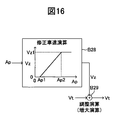
- the reliability evaluation apparatus for curve information acquires vehicle position acquisition means for acquiring the position (Pvh) of the vehicle and curve information (Rc, Pc) of the road on which the vehicle travels.
- Curve information acquisition means actual turning state quantity acquisition means for acquiring an actual turning state quantity (Ta) representing an actual turning state of the vehicle, and actual vehicle state based on the actual turning state quantity (Ta). Based on the actual turning index calculating means for calculating the actual turning index (Sa), which is an index representing the degree of turning, the vehicle position (Pvh) and the curve information (Rc, Pc), the actual turning index (Sa ) Based on the result of comparison between the actual turning index (Sa) and the calculated turning index (Se) (Rc). , Pc) And a reliability calculating means for calculating a sq).
- the vehicle travel control apparatus includes a vehicle position acquisition unit that acquires a vehicle position, a curve information acquisition unit that acquires curve information about a curve of a road on which the vehicle travels, and a speed of the vehicle.
- Vehicle speed acquisition means for acquiring; deceleration control means for executing deceleration control for decreasing the speed of the vehicle when the vehicle passes the curve based on the position of the vehicle, the curve information, and the speed of the vehicle;
- An actual turning state amount acquisition unit that acquires an actual turning state amount that represents an actual turning state of the vehicle, and the deceleration control unit executes the deceleration control based on the actual turning state amount. It can also be described as a configured device.
- the vehicle travel control apparatus includes a vehicle position acquisition unit that acquires a position of the vehicle, a curve information acquisition unit that acquires curve information regarding a curve of a road on which the vehicle travels, Vehicle speed acquisition means for acquiring a speed, turn detection means for detecting a turn of the vehicle with respect to the curve, and when a turn of the vehicle with respect to the curve is detected, the position of the vehicle, the curve information, and the vehicle It can also be described as a device comprising deceleration control means for executing deceleration control for reducing the speed of the vehicle when the vehicle passes the curve based on the speed.
- FIG. 1 is a schematic configuration diagram of a vehicle equipped with a vehicle travel control apparatus according to a first embodiment of the present invention.
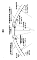
- FIG. 2 is a diagram showing an example of the shape of the curve.
- FIG. 3 is a diagram showing an example of changes in the radius of curvature and the turning state amount for the curve shown in FIG.
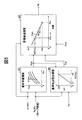
- FIG. 4 is a functional block diagram for explaining an outline of deceleration control and stabilization control executed by the travel control device shown in FIG.
- FIG. 5 is a functional block diagram for explaining calculation of the target vehicle speed by the target vehicle speed calculation means shown in FIG.
- FIG. 6 is a functional block diagram for explaining the calculation of the deceleration control target value by the deceleration control target value calculating means shown in FIG.
- FIG. 1 is a schematic configuration diagram of a vehicle equipped with a vehicle travel control apparatus according to a first embodiment of the present invention.
- FIG. 2 is a diagram showing an example of the shape of the curve.
- FIG. 3 is a diagram showing an example
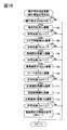
- FIG. 7 is a functional block diagram for explaining calculation of the determination result by the execution feasibility determination unit shown in FIG. 4 and calculation of the stabilization control target value by the stabilization control target value calculation unit.
- FIG. 8 is a functional block diagram for explaining the calculation of the braking control target value by the target value adjusting means shown in FIG.
- FIG. 9 is a time chart showing an example when deceleration control is executed by the travel control device shown in FIG.
- FIG. 10 shows a vehicle travel control apparatus according to a modification of the first embodiment of the present invention.
- the final determination result by the execution determination unit shown in FIG. 4 is invalid based on a plurality of determination calculation results. It is the flowchart which showed an example of the process about the case where it changes into a valid state from a state.
- FIG. 8 is a functional block diagram for explaining calculation of the braking control target value by the target value adjusting means shown in FIG.
- FIG. 9 is a time chart showing an example when deceleration control is executed by the travel control device shown in
- FIG. 11 is a functional block diagram for explaining the determination calculation based on the azimuth angle shown in FIG.
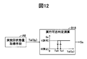
- FIG. 12 is a functional block diagram for explaining a determination calculation based on the actual turning state quantity shown in FIG.
- FIG. 13 is a functional block diagram for explaining the determination calculation based on the comparison between the turning direction and the curve direction shown in FIG.
- FIG. 14 is a functional block diagram for explaining a determination calculation based on a comparison between the calculated turning index and the actual turning index shown in FIG.
- FIG. 15 shows that the final determination result by the execution determination unit shown in FIG. 4 is valid based on a plurality of determination calculation results in the vehicle travel control apparatus according to the modification of the first embodiment of the present invention.
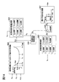
- FIG. 16 is a functional block diagram for explaining calculation when the target vehicle speed is adjusted based on the operation amount of the acceleration operation member by the driver.
- FIG. 17 is a flowchart showing an example of processing related to the calculation of the azimuth shown in FIG.
- FIG. 18 is a diagram for explaining an example of the calculation of the azimuth angle in the case of a single curve.
- FIG. 19 is a diagram for explaining an example of the calculation of the azimuth angle in the case of the composite curve.
- FIG. 20 is a functional block diagram for explaining an outline of the curve information reliability evaluation executed by the vehicle travel control apparatus (curve information reliability evaluation apparatus) according to the second embodiment of the present invention.
- FIG. 16 is a functional block diagram for explaining calculation when the target vehicle speed is adjusted based on the operation amount of the acceleration operation member by the driver.
- FIG. 17 is a flowchart showing an example of processing related to the calculation of the azimuth shown in FIG.
- FIG. 18 is a diagram for explaining an example of the calculation of the azi
- FIG. 21 is a diagram illustrating a calculation example of the calculated turning index and the actual turning index.
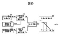
- FIG. 22 is a functional block diagram for explaining an overview of vehicle speed control executed by the vehicle travel control apparatus according to the second embodiment of the present invention.
- FIG. 23 is a functional block diagram for explaining the determination calculation by the first execution possibility determination unit shown in FIG.
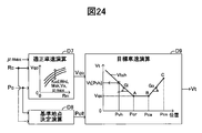
- FIG. 24 is a functional block diagram for explaining the calculation of the target vehicle speed by the target vehicle speed calculation means shown in FIG.
- FIG. 25 is a functional block diagram for explaining the reference point determination calculation shown in FIG.
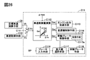
- FIG. 26 is a functional block diagram for explaining the vehicle speed control by the vehicle speed control means shown in FIG.
- FIG. 27 is a time chart for explaining that the change gradient of the braking torque is limited by the limiting means of the wheel brake control means shown in FIG.
- FIG. 28 is a time chart showing an example when vehicle speed control is executed by the vehicle travel control apparatus according to the second embodiment of the present invention.
- FIG. 29 is a functional block diagram for explaining calculation when the target vehicle speed is adjusted based on the operation amount of the acceleration operation member by the driver.
- FIG. 30 is a functional block diagram for explaining the second and third execution feasibility judgment calculations performed in addition to the first execution feasibility judgment calculation.
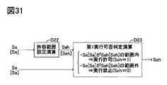
- FIG. 31 is a functional block diagram for explaining a case where an allowable range is considered when comparing the actual turning index and the calculated turning index.
- FIG. 32 is a graph for explaining an example of the allowable range shown in FIG.
- FIG. 1 shows a schematic configuration of a vehicle equipped with a travel control device (hereinafter sometimes referred to as “the present device”) according to a first embodiment of the present invention.
- This device includes an engine EG that is a power source of the vehicle, an automatic transmission TM, a brake actuator BRK, an electronic control unit ECU, and a navigation device NAV.
- the engine EG is, for example, an internal combustion engine. That is, the opening degree of the throttle valve TV is adjusted by the throttle actuator TH according to the operation of the accelerator pedal (acceleration operation member) AP by the driver.
- the automatic transmission TM is a multi-stage automatic transmission having a plurality of shift stages or a continuously variable automatic transmission having no shift stages.
- the brake actuator BRK has a known configuration including a plurality of solenoid valves, a hydraulic pump, a motor, and the like. When not being controlled, the brake actuator BRK supplies a brake pressure (brake hydraulic pressure) corresponding to the operation of the brake pedal (brake operation member) BP by the driver to the wheel cylinder WC ** of the wheel WH **, respectively. In some cases, the brake pressure in the wheel cylinder WC ** can be adjusted for each wheel independently of the operation of the brake pedal BP (and the operation of the accelerator pedal AP).
- the wheel cylinder WC ** comprehensively indicates a left front wheel wheel cylinder WCfl, a right front wheel wheel cylinder WCfr, a left rear wheel wheel cylinder WCrl, and a right rear wheel wheel cylinder WCrr.
- This device includes a wheel speed sensor WS ** that detects a wheel speed of the wheel WH **, a brake pressure sensor PW ** that detects a brake pressure in the wheel cylinder WC **, and a steering wheel SW (from a neutral position).
- a steering wheel angle sensor SA for detecting the rotation angle
- a front wheel steering angle sensor FS for detecting the steering angle of the front wheels
- a yaw rate sensor YR for detecting the yaw rate of the vehicle body
- an acceleration (deceleration) in the vehicle longitudinal direction A
- An acceleration operation amount sensor AS for detecting the operation amount a braking operation amount sensor BS for detecting an operation amount of the brake pedal BP, and a shift lever S
- a shift position sensor HS for detecting the position of the throttle valve
- a throttle valve opening sensor TS for detecting the opening of the throttle valve TV
- a self-aligning torque sensor ATf * for detecting the self-aligning torque of the steered wheel (front wheel)
- a steering torque sensor ST for detecting the steering torque of the steering wheel SW.
- the self-aligning torque sensor ATf * is fixed to the wheel rim of the steered wheel, for example, and detects the distortion of the wheel rim. Based on the information on the distortion and the position of the wheel rim where the distortion is detected, Detect self-aligning torque.
- the electronic control unit ECU is a microcomputer that electronically controls the powertrain system and the chassis system.
- the electronic control unit ECU is electrically connected to the various actuators described above, the various sensors described above, and the automatic transmission TM, or can communicate with a network.
- the electronic control unit ECU is composed of a plurality of control units (ECU1 to ECU4) connected to each other via a communication bus CB.
- the ECU 1 in the electronic control unit ECU is a wheel brake control unit and controls the brake actuator BRK based on signals from the wheel speed sensor WS **, the longitudinal acceleration sensor GX, the lateral acceleration sensor GY, the yaw rate sensor YR, and the like.
- braking pressure control wheel brake control
- ESC control vehicle stabilization control
- ABS control anti-skid control
- TCS control traction control
- the ECU 1 calculates a vehicle speed (vehicle speed) Vx based on a detection result (wheel speed Vw **) of the wheel speed sensor WS **.
- the ECU 2 in the electronic control unit ECU is an engine control unit that controls the output torque of the engine EG (engine control) by controlling the throttle actuator TH and the fuel injection actuator FI based on signals from the acceleration operation amount sensor AS and the like. Is supposed to run.
- the ECU 3 in the electronic control unit ECU is an automatic transmission control unit, and executes a reduction ratio control (transmission control) by controlling the automatic transmission TM based on a signal from the shift position sensor HS or the like. It has become.
- the ECU 4 in the electronic control unit ECU is an electric power steering control unit, and executes power steering control by controlling the electric power steering device EPS based on a signal from the steering torque sensor ST or the like.
- the navigation device NAV includes a navigation processing device PRC.
- the navigation processing device PRC includes a vehicle position detection means (global positioning system) GPS, a yaw rate gyro GYR, an input unit INP, a storage unit MAP, and a display unit (display). ) Electrically connected to the MTR.
- the navigation device NAV is electrically connected to the electronic control unit ECU or can communicate wirelessly.
- the vehicle position detection means GPS can detect the position (latitude, longitude, etc.) of the vehicle by one of the well-known methods using a positioning signal from an artificial satellite.
- the yaw rate gyro GYR can detect the angular velocity (yaw rate) of the vehicle body.
- the input unit INP is configured to input an operation related to the navigation function by the driver.
- the storage unit MAP stores various information such as map information and road information.
- the navigation processing device PRC comprehensively processes signals from the vehicle position detection means GPS, the yaw rate gyro GYR, the input unit INP, and the storage unit MAP, and displays the processing result (information related to the navigation function) on the display unit MTR. It is supposed to be.
- the (one) curve shown in FIG. 2 has a gradually decreasing curvature radius as the vehicle progresses in order from the curve start point Ci (curve entrance) to the curve end point Cd (curve exit).
- a constant curvature radius section Zit and an exit relaxation curve section Zcd (the curvature radius gradually increases as the vehicle advances).
- the relaxation curve is composed of a clothoid curve, for example.
- the relaxation curve section is provided so that the vehicle can smoothly pass the curve by gradually turning the steering wheel and then gradually turning back without requiring the driver to operate the steering wheel suddenly. It is for doing so.
- the radius of curvature is infinite at the curve start point Ci (that is, the end point of the straight road) and then gradually decreases to the start point of the constant curvature radius section Zit.
- Cs is Rm (the minimum radius of curvature in the curve).
- the radius of curvature is maintained at Rm until the end point Ce of the constant curvature radius section Zit, and then gradually increases and becomes infinite at the curve end point Cd (that is, the start point of the straight road).
- the turning state amount for example, lateral acceleration
- the turning state quantity starts to increase from “0 (straight travel)” at the curve start point Ci, and is approximately proportional in the approach relaxation curve section Zci.
- the constant curvature radius section Zit it becomes a constant value (maximum value).
- the turning state quantity decreases approximately proportionally in the exit relaxation curve section Zcd, and becomes “0 (straight running)” at the curve end point Cd.
- the “deceleration control” for decelerating the vehicle on the curve is required near the start point Cs of the constant curvature radius section Zit where the curvature radius becomes small on the curve.
- the steering characteristic of the vehicle does not require an intervention of “stabilization control” that stabilizes the turning state of the vehicle, but tends to be an understeer tendency in many cases.
- “stabilization control” that stabilizes the turning state of the vehicle, but tends to be an understeer tendency in many cases.
- the curve information Rc, Pc is stored in the map information database of the storage unit MAP.
- the position Pc for example, latitude / longitude information
- the curvature radius Rc of the curve at the position Pc can be directly stored.
- a format for example, an arithmetic expression and a coefficient
- a target vehicle speed Vt for stably passing through the target curve is calculated based on the curve information Rc, Pc and the vehicle position Pvh.
- the deceleration control target value calculation means A4 the target vehicle speed Vt and the vehicle speed Vx acquired by the vehicle speed acquisition means A5 are compared, and the deceleration control target value Gst (the target value of the wheel brake, the target value of the braking torque) Is calculated.
- the deceleration control target value Gst is determined based also on the determination result (control flag) So calculated by the execution permission determination means A9 described later.
- the calculated deceleration control target value Gst is output as it is to the target value adjusting means A11 described later.
- the actual turning state quantity acquisition means A6 acquires the actual yaw motion state quantity (actual turning state quantity Ta) of the vehicle.
- the actual turning state amount Ta is a yawing motion state amount actually generated with respect to the vehicle, and is, for example, the actual yaw rate Yr, the actual lateral acceleration Gy, the actual vehicle body slip angle ⁇ a, and the actual vehicle body slip angular velocity d ⁇ a. Further, a value obtained by combining two or more state quantities from among these can be used as the actual motion state quantity Ta.
- the target yaw motion state quantity (target turning state quantity Td) of the vehicle is acquired.
- the target turning state amount Td values of the same dimension (target yaw rate Yrd, target lateral acceleration Gyd, target vehicle body slip angle ⁇ d, target vehicle body slip angular velocity d ⁇ d) corresponding to the actual turning state amount Ta are calculated.
- the target turning state amount Td is calculated based on the vehicle speed Vx and the steering wheel angle ⁇ sw (or the front wheel steering angle ⁇ f).
- the vehicle steering characteristics (understeer, neutral steering, oversteer) are calculated based on the actual turning state quantity Ta and the target turning state quantity Td, and the calculation result (steer characteristic value) Sch is calculated.
- the steer characteristic value Sch is calculated to be a positive value.
- the steer characteristic can be calculated based only on the actual turning state amount Ta without using the target turning state amount Td.
- the steering characteristic value Sch can be calculated based on the actual vehicle body slip angular velocity d ⁇ a, the actual vehicle body slip angle ⁇ a, and the like.
- a judgment result (control flag) So of the execution of deceleration control is determined based on the steering characteristic value Sch.
- the final determination result by the feasibility determination unit A9 can be determined based on determination results (control flags Sy, Sd, Ss, Sm) other than the determination result (control flag) So based on the steer characteristic value Sch. . These will be described in detail later.
- the determination result by the execution feasibility determination unit A9 is determined based only on the determination result (control flag) So based on the steer characteristic value Sch.
- Sch ⁇ Sc1 predetermined value
- This determination is based on the assumption that “when the steering characteristic value is small, there is a low possibility that the vehicle is actually traveling in the curve (thus, the reliability of the curve information is low)”.
- “0” is output to the target value adjusting unit A11 as the deceleration control target value Gst.
- the predetermined value Sc1 is a threshold value for determining an understeer tendency of the vehicle. This determination is “at a stage where the steering characteristic value is large, there is a high possibility that the vehicle tends to understeer and the vehicle is actually traveling in the curve (thus, the reliability of the curve information is high).” Based on what is considered. As a result, the value calculated based on the comparison between the target vehicle speed Vt and the vehicle speed Vx is output as it is to the target value adjusting means A11 as the deceleration control target value Gst.
- the stabilization control target value Est (the target value of the wheel brake and the target value of the braking torque) is calculated based on the steering characteristic value Sch.
- Stabilization control is a known control that suppresses understeer and oversteer of a vehicle.
- the target value adjusting means A11 the deceleration control target value Gst and the stabilization control target value Est are adjusted, and the braking control target value Bt is calculated.
- the start condition of the stabilization control is Sch> Sc2 (predetermined value).
- the actual braking control amount (for example, braking pressure) Ba is controlled based on the braking control target value Bt.
- the wheel brake control means A12 for example, known means constituted by a pump, an electric motor, a solenoid valve, or the like can be used.
- This actual braking control amount (for example, braking pressure) Ba is output to the wheel brake means A13, and as a result, a braking force is generated on the wheel.
- wheel brake means A13 the well-known means comprised by a caliper, a rotor, a pad, etc. can be used, for example.
- the final determination result by the feasibility determination unit A9 is also based on determination results (control flags Sy, Sd, Ss, Sm) other than the determination result (control flag) So based on the steer characteristic value Sch. It can finally be determined.
- determination results control flags Sy, Sd, Ss, Sm
- control flag So based on the steer characteristic value Sch.
- it can finally be determined.
- a curvature radius Rm of a section where the curvature radius in the curve is constant (constant curvature radius section Zit) is determined, and the appropriate vehicle speed Vqo is determined based on the curvature radius Rm. Calculated. As the radius of curvature Rm, the minimum radius of curvature in the curve can also be used. The greater the curvature radius Rm, the greater the appropriate vehicle speed Vqo is calculated. Thus, the appropriate vehicle speed Vqo is determined so that the vehicle can pass the curve with substantially the same lateral acceleration regardless of the curvature radius Rm.
- the appropriate vehicle speed Vqo can be adjusted based on at least one of the uphill / downhill gradient Kud, the road width (width) Wrd, the forward view Msk, and the vehicle speed Vx.
- the uphill slope Kud is downhill
- the appropriate vehicle speed Vqo is adjusted to a lower value than when the road is flat, and when uphill, the appropriate vehicle speed Vqo is higher than that when the road is flat. Adjusted.
- the road width Wrd is narrow, the appropriate vehicle speed Vqo is adjusted to a smaller value than when the road width Wrd is wide.
- the road width Wrd is wide, the appropriate vehicle speed Vqo is adjusted to a larger value than when the road width Wrd is narrow. Is done.
- the appropriate vehicle speed Vqo is adjusted to a smaller value than when the forward view Msk is good.
- the appropriate vehicle speed Vqo is higher than when the forward view Msk is bad. Adjusted to a larger value.
- the vehicle speed Vx is high, the appropriate vehicle speed Vqo is adjusted to a smaller value than when the vehicle speed Vx is low, and when the vehicle speed Vx is low, the appropriate vehicle speed Vqo is adjusted to a larger value than when the vehicle speed Vx is high. Is done.
- the appropriate vehicle speed Vqo can also be adjusted based on the road surface friction coefficient ⁇ max.
- the appropriate vehicle speed Vqo is adjusted to a larger value than when the road surface friction coefficient ⁇ max is small, and when the road surface friction coefficient ⁇ max is small, the road surface friction coefficient ⁇ max is large. In comparison, the appropriate vehicle speed Vqo is adjusted to a smaller value.
- the calculation of the road surface friction coefficient ⁇ max is performed based on the wheel self-aligning torque Sat acquired by the self-aligning torque sensor ATf *. In the process in which the lateral force of the wheel increases, the self-aligning torque Sat also increases. In this process, the self-aligning torque Sat becomes the maximum value before reaching the state where the lateral force is saturated (that is, the turning limit state).
- the road surface friction coefficient ⁇ max can be estimated before the turning of the vehicle reaches the limit.
- the self-aligning torque Sat for example, one of known methods described in Japanese Patent Application Laid-Open Nos. 2008-24073, 2007-245901, and 2004-233331 is used. it can.
- the calculation of the road surface friction coefficient ⁇ max based on the self-aligning torque for example, one of known methods described in Japanese Patent Application Laid-Open No. 2007-245901 can be used.
- the reference point Pcr is determined.
- the reference point Pcr is a target point for reducing the vehicle speed to the appropriate vehicle speed Vqo by the deceleration control.
- the reference point Pcr can be set to an entrance point Cs (a point closest to the vehicle in the constant curvature radius section) where the curvature radius in the curve is constant. Further, the point Cs where the radius of curvature in the curve is minimum can be set as the reference point Pcr.
- the point Cs is determined based on the curve shape Rc and the curve position Pc.
- the point Pcr is set to the entrance point Cs of the constant curvature radius section or a point closer to the vehicle by the distance Lpr than the minimum curvature radius point (near the end of the relaxation curve corresponding to the entry part to the curve closer to the vehicle). be able to.
- the distance Lpr can be a constant value.
- the distance Lpr can be calculated according to the vehicle speed Vx.
- the distance Lpr is “0” (that is, the point Pcr coincides with Cs), and when Vx> V1 (predetermined value), the vehicle speed Vx increases from V1.
- the distance Lpr can be determined such that the distance Lpr increases from “0”.
- the vehicle speed Vx can be replaced with the appropriate vehicle speed Vqo, and the distance Lpr can be determined based on the appropriate vehicle speed Vqo.
- the point Pcr is set to a point on the curve close to the curve start point Ci by the distance Lpr from the point Cs.
- the point Pcr is set based on the distance Lpr, the curve shape Rc, and the point Cs (curve position Pc).
- the point Pcr is a target point for reducing the vehicle speed to the appropriate vehicle speed Vqo.
- the map information or the like may include an error.
- the error can be absorbed. That is, the vehicle speed control is started earlier in the curve, and the vehicle speed can be surely reduced to the appropriate vehicle speed Vqo at a point on the curve closer to the curve entrance Ci than the point Pcr.
- the target vehicle speed calculation block B3 the target vehicle speed Vt is calculated.
- a target vehicle speed calculation characteristic Vtch for calculating the target vehicle speed Vt (Vt [Pvh]) at the vehicle position Pvh is determined.
- the target vehicle speed calculation characteristic Vtch is a characteristic in which the vehicle speed decreases with a deceleration Gm (for example, a preset constant) from the curve entrance side to the reference point Pcr, and the vehicle speed becomes the appropriate vehicle speed Vqo at the reference point Pcr.
- the deceleration Gm can be set to a value in consideration of a general road surface friction coefficient on a wet road surface.
- the deceleration Gm can be adjusted based on the road surface friction coefficient ⁇ max.
- the deceleration Gm can be adjusted to a larger value as the road surface friction coefficient ⁇ max is larger.
- the target vehicle speed Vt at the vehicle position Pvh is calculated by inputting the vehicle position Pvh to the target vehicle speed calculation characteristic Vtch determined based on the reference point Pcr and the appropriate vehicle speed Vqo.
- the target vehicle speed Vt calculated in this way is output to the deceleration control target value calculation means A4 (see FIG. 4).
- the deceleration control target value calculation block B5 the deceleration control target value Gst is calculated based on the vehicle speed deviation ⁇ Vx. Specifically, the greater the deviation ⁇ Vx (> 0), the larger the deceleration control target value Gst is calculated. When the deviation ⁇ Vx is negative, Gst is calculated to “0”.
- deceleration control is executed when the vehicle speed Vx is higher than the target vehicle speed Vt (Vx> Vt), and deceleration control is not executed when the vehicle speed Vx is lower than the target vehicle speed Vt (Vx ⁇ Vt).
- the deceleration control target value Gst can be adjusted based on the road surface friction coefficient ⁇ max. Specifically, the deceleration control target value Gst is adjusted to a larger value as the road surface friction coefficient ⁇ max is larger. Thus, the deceleration control target value Gst calculated in the block B5 is output to the switching calculation block B6.
- the deceleration control target value Gst calculated in the block B5 is output as it is as the final deceleration control target value Gst.
- the final deceleration control target value Gst calculated and selected in this way is output to the target value adjusting means A11 (see FIG. 4).
- the final determination result by the execution determination unit A9 is also based on determination results (control flags Sy, Sd, Ss, Sm, which will be described later) other than the determination result (control flag) So based on the steer characteristic value Sch.
- the final deceleration control target value Gst is calculated and selected based on the final determination result by the execution determination unit A9.
- a target turning state calculation block B7 a yaw motion state amount (target turning state amount) Td of a target vehicle is calculated.
- Td a physical quantity of the same dimension corresponding to the actually generated yawing motion state quantity (actual turning state quantity) Ta is calculated.
- the target yaw rate Yrd is calculated as the target turning state quantity Td.
- Kh is a stability factor
- L is a wheel base of the vehicle
- SG is a steering gear ratio of the vehicle.
- the steer characteristic of the vehicle is calculated by comparing the target turning state quantity Td with the actual turning state quantity Ta of the same dimension corresponding to the target turning state quantity Td.
- the steer characteristic value Sch is approximately “0”, the vehicle is neutral steer.
- Sch ⁇ 0 the vehicle is oversteered, and the degree of oversteer increases as the absolute value of the steer characteristic value Sch increases.
- Sch>0 the vehicle is understeer, and the degree of understeer increases as the steer characteristic value Sch increases.
- the steer characteristic value Sch is calculated using the yaw rate
- ⁇ Yr Yrd ⁇ Yr
- the steer characteristic when the yaw rate deviation ⁇ Yr is approximately “0”, the vehicle is neutral steer.
- ⁇ Yr ⁇ 0 the vehicle is oversteered, and the greater the absolute value of the deviation ⁇ Yr, the greater the degree of oversteer.
- ⁇ Yr>0 the vehicle is understeer, and the degree of understeer increases as the deviation ⁇ Yr increases.
- the execution possibility determination calculation block B9 it is determined whether or not the deceleration control can be executed.
- the steer characteristic value Sch or the yaw rate deviation ⁇ Yr
- Sc1 preset
- the steer characteristic value Sch (or yaw rate deviation ⁇ Yr) is a predetermined value (set in advance).
- Sc0 ⁇ Sc1 there is a relationship of Sc0 ⁇ Sc1 between the predetermined values Sc0 and Sc1.
- the predetermined value Sc1 is set to a value smaller than a predetermined value Sc2 described later.
- the stabilization control target value Est is calculated based on the steer characteristic value Sch (or yaw rate deviation ⁇ Yr). Specifically, when the steer characteristic value Sch (or yaw rate deviation ⁇ Yr) is equal to or smaller than a predetermined value Sc2 (preset), the stabilization control target value Est is calculated to “0”. That is, Sch> Sc2 is a start condition for the stabilization control.
- the stabilization control target value Est is determined independently for each wheel so as to suppress excessive understeer and oversteer of the vehicle and maintain the steering characteristic appropriately.
- “fo” represents the front wheel outside the turn
- “ro” represents the rear wheel outside the turn
- “ri” represents the stabilization control target value Est for the rear wheel inside the turn.
- the braking control target value Bt is calculated by adding the stabilization control target value Est to the deceleration control target value Gst by “increase calculation”.
- the deceleration control target value Gst is stabilized by “selection calculation”. The control target value Est is adjusted.
- the wheel speed Vw ** detected by the wheel speed sensor WS ** (the subscript “**” indicates which wheel the symbol relates to, “fl” is the front left wheel, “fr”
- the braking torque applied to the wheel cannot be further increased.
- the deceleration control target value Gst is directly output to the wheel brake control means A12 as the braking control target value Bt for that wheel.
- the vehicle moment is appropriately generated.
- a value obtained by subtracting the stabilization control target value Est from the deceleration control target value Gst by the “decrease calculation” is output to the wheel brake control means A12 as the braking control target value Bt.
- the actual braking torque Ba (braking pressure) applied to the wheel brake means A13 is controlled based on the braking control target value Bt.
- the braking torque time gradient limiting means limits the change gradient with respect to time of the braking torque. Specifically, the increase gradient with respect to the time of Ba is limited to the predetermined value Lwc, and the decrease gradient with respect to the time of Ba is limited to the predetermined value Lwd.
- the deceleration control can be executed using the deceleration that can be adjusted by using the downshift of the automatic transmission TM.
- the deceleration control is not started, and the actual braking torque (braking pressure) Ba is also maintained at “0”.
- the vehicle enters the curve (passes the curve start point Ci), and the steering characteristic value Sch starts increasing from “0”.
- the deceleration control target value Gst is switched to a value (> 0) calculated based on ⁇ Vx. That is, the deceleration control is started, and the actual braking torque Ba (> 0) is started to be applied. As a result, the vehicle starts to decelerate.
- the time gradient limit Lwc is provided for the increase in the braking torque. For this reason, even if deceleration control is suddenly started, the actual braking torque (braking pressure) Ba does not increase suddenly, and therefore the vehicle is not suddenly decelerated.
- the steering characteristic value Sch becomes smaller than the predetermined value Sc0 ( ⁇ predetermined value Sc1).
- the time gradient limit Lwd is provided for the reduction of the braking torque. For this reason, even if the deceleration control is terminated suddenly, the actual braking torque (braking pressure) Ba does not decrease rapidly, and therefore the vehicle deceleration does not decrease rapidly. In the example shown in FIG.
- the deceleration control may be started when the condition (deceleration control start condition) is satisfied. As shown in FIG. 9, in this device, the deceleration control is started when the curvature radius Rc of the curve after entering the curve gradually decreases and the steering characteristic value Sch reaches a value indicating an understeer tendency.
- the steer characteristic value Sch does not reach a value indicating an understeer tendency, and thus deceleration control is not executed. That is, it is possible to prevent the deceleration control from being started and executed unnecessarily based on the low-reliability curve information.
- the deviation (steer characteristic value Sch) between the target turning state amount Td and the actual turning state amount Ta is calculated after the vehicle enters the curve.
- the deceleration control can be executed based only on the curve information with high reliability.
- the processing is started when the acquired curve information Rc, Pc and the actual curve shape are different due to the modification of the curve in the vicinity of the curve entrance (particularly, the modification from the curve to the straight road). It is possible to inhibit the deceleration control that should not be started.
- the present invention is not limited to the first embodiment, and various modifications can be employed within the scope of the present invention.
- the determination result by the execution feasibility determination unit A9 is based only on the determination result (control flag) So based on the steer characteristic value Sch, but the final determination result by the execution propriety determination unit A9
- the (control flag Sfin) may be determined based on another determination result (control flags Sy, Sd, Ss, Sm) instead of or in addition to the determination result (control flag) So based on Sch.
- control flag Sfin when the control flag Sfin is “1”, it indicates that the final determination result by the execution determination unit A9 is in a permitted state (a state in which the execution of the deceleration control is permitted), and when the control flag Sfin is “0” It represents that the final determination result by the permission determination means A9 is a prohibited state (a state in which execution of deceleration control is prohibited).
- the “prohibited state” corresponds to the “invalid state”, and the “permitted state” corresponds to the “valid state”.
- the routine corresponding to this flowchart is repeatedly executed every elapse of a predetermined time (for example, 6 msec).
- a predetermined time for example, 6 msec.
- the azimuth angle Ya is an angle formed by the traveling direction of the vehicle at the vehicle position (the direction in which the vehicle is facing) with respect to the direction of the straight line portion before the curve entrance.
- the “direction of the straight line portion before the curve entrance” is determined based on, for example, the straight line portion based on the transition of the actual turning state amount within a predetermined distance (for example, 20 m) in which the vehicle has traveled. It can be determined based on the traveling direction of the vehicle on the straight line portion.
- the predetermined distance is an error in the position of the curve entrance Ci determined based on the map information stored in the storage unit MAP, and an error in the vehicle position Pvh acquired by the global positioning system GPS or the like. Etc. are determined to values that can be absorbed.
- the azimuth angle Ya is calculated based on the actual turning state amount Ta (for example, the actual yaw rate Yr).
- the actual yaw rate Yr is acquired as the actual turning state amount Ta
- the azimuth (yaw angle) Ya is calculated by integrating (integrating) Yr from the curve entrance Ci.
- the azimuth angle Ya2 at the curve exit Cd (or the end point Ce of the constant curvature radius section) is calculated based on the curve information Rc and Pc.
- the azimuth angle Ya2 is an angle formed by the tangential direction of the curve at the curve exit Cd (or the point Ce) with respect to the direction of the straight line portion before the curve entrance.
- a predetermined value Ya1 is calculated based on the vehicle speed Vx. Specifically, the greater the vehicle speed Vx, the smaller the predetermined value Ya1 is calculated.
- the determination calculation is “at a stage where the azimuth angle Ya is small (less than Ya1), the possibility that the vehicle is actually traveling in the curve is low (thus, the reliability of the curve information is low), and Ya is large ( At the stage of Ya1 or higher), it is highly likely that the vehicle is actually traveling in the curve (thus, the reliability of the curve information is high).
- the azimuth angle Ya is an integrated value of the actual yaw rate Yr from the curve entrance Ci. Therefore, even when the position of the vehicle fluctuates in the width direction of the road after entering the curve (when the vehicle fluctuates), the azimuth angle Ya can represent the traveling direction of the vehicle when viewed macroscopically. .
- the determination result (control flag) Sy accurately determines whether the reliability of the curve information is high, that is, whether or not the deceleration control can be executed. can do.
- the azimuth angle Ya is equal to or greater than the predetermined value Ya1” corresponds to “the turning with respect to the curve is detected”.
- “turning with respect to a curve” may be detected based not only on the calculated azimuth angle but also on a detected value (actual measurement value) such as an actual yaw rate or steering wheel angle, or may be an imaging device such as an in-vehicle camera. Alternatively, it may be detected using a sensor such as a millimeter wave laser radar.
- the three-dimensional object moves at a constant speed in the screen according to the vehicle speed, and the position of the three-dimensional object in the screen changes. At this time, the three-dimensional object moves in a fixed manner around the vanishing point in the screen. However, when the left / right turn is performed, the three-dimensional object moves uniformly left and right from the screen edge in the screen. Accordingly, the “turning with respect to the curve” may be detected based on the detection that the three-dimensional object in the screen moves uniformly left and right from the screen edge.
- a turn is made based on the “positional relationship between the detected object (stationary object) and the own vehicle” and the “vehicle speed of the own vehicle”. It becomes possible to judge. Specifically, when a stationary object is detected during turning, the stationary object moves in the horizontal direction within the screen, and the distance between the stationary object and the host vehicle becomes longer. Therefore, when a stationary object is detected and the detection result indicates that the stationary object moves laterally in the screen and the distance between the stationary object and the own vehicle becomes longer after that, "Turning with respect to a curve" may be detected. Referring to FIG.
- step 103 if “No” is determined in step 103 (Ya ⁇ Ya1), this routine is immediately terminated.
- the calculation of the determination result (control flag) So based on Sch (the processing of steps 104 and 105) is the same as the calculation of blocks B7, B8, and B9 shown in FIG. If “No” is determined in step 105 (Sch ⁇ Sc1), this routine is immediately terminated.
- the calculation of the determination result (control flag) Ss based on Ta (processing in steps 106 and 107) will be described in detail with reference to FIG.
- the actual turning state amount acquisition means A6 acquires the actual turning state amount Ta (for example, the actual lateral acceleration Gy).
- the determination result (control) is performed at a stage where the actual turning state amount Ta (for example, Gy) is less than the predetermined value Ta1.
- the determination calculation is as follows: “At the stage where the actual turning state amount Ta (for example, Gy) is small (less than Ta1), the possibility that the vehicle is actually traveling in the curve is low (therefore, the reliability of the curve information is low). Low), when Ta (for example, Gy) is large (Ta1 or higher), the vehicle is likely to actually travel in the curve (thus, the reliability of the curve information is high). based on. On the other hand, in the process in which the actual turning state amount Ta (for example, Gy) is decreasing, the determination result (control flag) Ss is in the permitted state when the actual turning state amount Ta (for example, Gy) is greater than the predetermined value Ta0.
- the calculation of the determination result (control flag) Sd based on Dvh and Dcv processing of steps 108, 109, and 110 will be described in detail with reference to FIG.
- the turning direction Dvh of the vehicle is identified based on the actual turning state amount Ta.
- the vehicle when the absolute value of the actual turning state amount Ta is less than the predetermined value Ts, the vehicle is identified as “straight ahead”.
- the absolute value of the actual turning state amount Ta is equal to or greater than the predetermined value Ts, the vehicle is identified as turning, and “left turning” or “right turning” is identified by the sign of the actual turning state amount Ta at that time.
- any one of “straight ahead”, “left turn”, and “right turn” is calculated as the turning direction Dvh.
- the curve direction Dcv with respect to the traveling direction of the vehicle is identified based on the curve information Rc, Pc and the vehicle position Pvh.
- the curve direction Dcv is identified as “straight line”.
- “left curve” or “right curve” is identified by the direction of the curve curvature radius Rvh. That is, any one of “straight line”, “left curve”, and “right curve” is calculated as the curve direction Dcv.
- the determination calculation is as follows: “If the turning direction Dvh and the curve direction Dcv match, the reliability of the curve information is high, and if the turning direction Dvh and the curve direction Dcv do not match, the reliability of the curve information is low”. Based on thoughts. Referring to FIG. 10 again, if “No” is determined in step 110 (Dvh and Dcv do not match), this routine is immediately terminated.
- step 111 the calculated turning index Se is calculated, and in the subsequent step 112, the actual turning index Sa is calculated, and the following step In step 113, a comparison result Sh between Se and Sa is calculated.
- the calculation of the determination result (control flag) Sm based on Sh (the processing of steps 111, 112, 113, and 114) will be described in detail with reference to FIG.
- the curve curvature radius calculation block B22 calculates the curvature radius Rvh of the curve at the vehicle position Pvh.
- the relationship (curvature radius calculation characteristic) Rch between the position Pc in the curve and the curvature radius Rc is calculated based on the curve information Rc, Pc.
- the radius-of-curvature calculation characteristic Rch can be estimated based on a curve obtained by connecting geometrically and smoothly the positions of a plurality of points (node points) on a road stored in advance (for example, Japanese Patent No. 3378490). See).
- the radius-of-curvature calculation characteristic Rch can be stored in a map information database using a function representing a relaxation curve (for example, a clothoid curve), a parameter, and the like.
- the curve curvature radius Rvh at the vehicle position Pvh is calculated. That is, by inputting the vehicle position Pvh to the curvature radius calculation characteristic Rch defined by the relationship between the position and the curvature radius, the curve curvature radius Rvh at the vehicle position Pvh is calculated.
- the calculated turning state quantity calculation block B23 the calculated turning state quantity Te is calculated based on the calculated curvature radius Rvh. The following state quantities can be calculated as the calculated turning state quantity Te.
- the calculated turning index Se is calculated based on the calculated turning state quantity Te.
- the curve curvature radius Rvh itself calculated as described above can be used as the calculated turning index Se.
- the calculated turning index Se can be calculated by combining two or more of the calculated turning indices Se described above.
- the actual turning index calculation block B25 the actual turning index Sa is calculated based on the actual turning state amount Ta.
- the same (dimensional) physical quantity (state quantity) is calculated as the actual turning index Sa and the calculated turning index Se.
- the curve curvature radius Rta is calculated based on the actual turning state amount Ta as the actual turning index Sa corresponding to the calculated turning index Se.
- Rta can be acquired by any of the following operations.
- Rta Vx 2 / Gya
- Rta Vx / Yra
- Rta [L ⁇ (1 + Kh ⁇ Vx 2 )] / ⁇ fa
- Rta [SG ⁇ L ⁇ (1 + Kh ⁇ Vx 2 )] / ⁇ swa
- Kh is a stability factor
- L is a wheel base of the vehicle
- SG is a steering gear ratio of the vehicle.
- the comparison calculation block B26 the calculated turning index Se and the actual turning index Sa are compared.
- the comparison result Sh the absolute value of the deviation between the actual turning index Sa and the calculated turning index Se (turning index deviation) can be used.
- a determination result (control flag) Sm is calculated based on the turning index deviation Sh.
- the determination calculation is as follows: “If the calculated turning index Se calculated based on the map information and the actually detected turning index Sa are substantially coincident (Sh ⁇ Sh1), the reliability of the curve information is high, If the difference between Se and Sa is large (Sh> Sh1), the reliability of the curve information is low ”.
- Such determination of whether or not to execute control is continued even after deceleration control is started.
- the deceleration control being executed can be stopped.
- the azimuth angle Ya, the steer characteristic value Sch, the actual turning state amount Ta, the turning direction Dvh, the curve direction Dcv, and the actual turning index Sa in the processing shown in FIG. 10 are determined state amounts (determining whether or not deceleration control can be executed).
- the predetermined values Ya1, Sc1, Ta1, Ts, Rvs, and Ths are the turning state of the vehicle when traveling on the entrance side from the central point of the approach relaxation curve section (entrance clothoid curve section) of the target curve, Or it can be set as the value equivalent to the state of a curve. Therefore, it is possible to complete the control execution determination in the first half portion of the target curve in the approach relaxation curve section.
- the vehicle speed control which decelerates a vehicle in the second half part in the approach relaxation curve area of the same curve can be started.
- the determination result based on Ya control flag Sy
- the determination result based on Sch control flag
- determination result based on Ta control flag Ss
- determination result based on Sh control flag Sm
- the “prohibited state” corresponds to the “invalid state”
- the “permitted state” corresponds to the “valid state”.
- a plurality of determination calculation results (Sy, So, Ss) corresponding to a plurality of determination state quantities (Ya, Sch, Ta, Dvh, Dcv, and Sa) calculated based on the actual turning state quantity Ta. , Sd, and Sm) by calculating the final determination result (control flag Sfin) by the execution determination unit A9 (see FIG. 4), it is possible to improve the determination accuracy of the deceleration control execution determination. it can.
- the execution start permission determination see FIG. 10
- the control prohibition determination during execution see FIG.
- the determination operation based on Ya the determination operation based on Sch, the determination operation based on Ta, and based on Dvh and Dcv
- the determination calculation and the determination calculation based on Sh are provided, and the calculation necessary for the determination calculation (for example, step 102 required for the determination calculation based on Ya) is included. At least one or more can be omitted. That is, at least one of the five determination calculations is provided, and an execution start permission determination and a control prohibition determination during execution are performed.
- any one of a determination calculation based on Ya, a determination calculation based on Sch, a determination calculation based on Ta, a determination calculation based on Dvh, Dcv, and a determination calculation based on Sh is “first execution”.
- any one of the determination operations different from the first execution determination unit corresponds to a “second execution determination unit different from the first execution determination unit”.
- the target vehicle speed Vt calculated in the target vehicle speed calculation means A3 shown in FIG. 4 (specifically, the block B3 shown in FIG. 5) is used as the acceleration operation of the driver's acceleration operation member AP. It can be adjusted in the increasing direction based on the amount Ap.
- the corrected vehicle speed Vz is calculated in the corrected vehicle speed calculation block B28 based on the acceleration operation amount Ap.
- the corrected vehicle speed Vz is calculated to be “0” when Ap is equal to or less than Ap1 (predetermined value), and to increase from “0” as Ap increases from Ap1. Furthermore, an upper limit Vz1 can be provided for the corrected vehicle speed Vz so that Ap is equal to or higher than Ap2 (predetermined value) and Vz is constant to Vz1 (predetermined value).
- the adjusted target vehicle speed Vt is output to the deceleration control target value calculation means A4 (see FIG. 4).
- step 301 an integration start point Psk that is a point at which the integration calculation of the azimuth angle Ya is started is set.
- the point Psk can be set as a point closer to the vehicle (near side) by a predetermined distance (predetermined value) Lsk from the curve entrance Ci.
- the point Psk is determined based on the position of the curve entrance Ci stored in the storage unit MAP (or calculated based on the information stored in the storage unit MAP). Further, the position of the point Psk can be stored in advance in the storage unit MAP.
- an integration end point Psl that is a point at which the integration calculation is ended is set.
- the point Psl can be set as a point closer to the vehicle (near side) by a predetermined distance (predetermined value) Lsl from Cd.
- the point Psl is determined based on the position of the curve exit Cd stored in the storage unit MAP (or calculated based on the information stored in the storage unit MAP). Further, the position of the point Psl can be stored in advance in the storage unit MAP.
- first curve the integration end point Psl1 corresponding to the curve closest to the vehicle
- second curve the curve closest to the vehicle
- second curve coincides with the integration start point Psk2 corresponding to (1)), or is present in front of the point Psk2 (side closer to the vehicle).
- step 303 it is determined whether or not the integration calculation of the azimuth angle Ya is being executed. Integration of the azimuth angle Ya has been started, and if an affirmative determination (YES) is made in step 303, the arithmetic processing proceeds to step 305. If the integration of the azimuth angle Ya has not yet been started and a negative determination (NO) is made in step 303, the arithmetic processing proceeds to step 304. In step 304, it is determined whether or not the vehicle has passed the point Psk. If the vehicle has not yet reached the point Psk, a negative determination is made in step 304, and the azimuth is not calculated.
- step 304 determines whether or not the vehicle has passed the point Psl. If the vehicle has reached or passed the point Psl, an affirmative determination is made in step 305, and the calculation process proceeds to step 309. In Step 309, the azimuth calculation (integration) is terminated, and the azimuth Ya is reset to “0”. On the other hand, if the vehicle has not yet reached the point Psl, a negative determination is made in step 305 and the calculation process proceeds to step 306.
- step 306 it is determined whether or not the actual turning state amount Ta (for example, the steering wheel angle ⁇ sw, the front wheel steering angle ⁇ f) is within a predetermined range (the absolute value
- the actual turning state amount Ta for example, the steering wheel angle ⁇ sw, the front wheel steering angle ⁇ f
- the azimuth angle Ya (integrated value) is set to “0”.
- step 308 an integral calculation (integration) process for calculating the azimuth angle Ya is performed.
- the azimuth Ya is reset when the actual turning state amount Ta is within a predetermined range as long as the vehicle has passed the point Psk and before the point Psl.
- the azimuth angle Ya may always be reset when the actual turning state amount Ta is within the predetermined range.
- An error is included in the position of the curve entrance Ci determined based on the information stored in the storage unit MAP.
- the vehicle position Pvh acquired by the global positioning system GPS or the like includes an error.
- the integration calculation of the azimuth angle Ya is started from a point before the curve entrance Ci by a predetermined value (predetermined distance) Lsk, so that these errors can be compensated.
- Lsk a value that can absorb these errors is used.
- Lsk can be set based on at least one of the accuracy of the storage unit MAP and the performance of GPS.
- the front side of the curve entrance Ci is a straight section, and the integration of the azimuth angle Ya is started before the curve entrance Ci (the side closer to the vehicle). For this reason, the azimuth angle Ya is calculated to be approximately zero in the section up to the curve entrance Ci.
- the actual turning state amount Ta (for example, the steering angle Str (a general term for ⁇ sw and ⁇ f)) is within a predetermined range (that is, Ta is within a range corresponding to straight running).
- the value of the azimuth angle Ya is reset and returned to “0”.
- the azimuth angle Ya is also generated when a lane change or the like is performed during straight running.
- Ta returns to “0” after the lane change is completed, the azimuth angle Ya is reset. Thereby, the approach into the curve of the vehicle can be reliably determined.
- FIGS. 18 and 19 the operation and effect will be described by the above-described calculation of the azimuth angle.
- a curve ahead of the vehicle is recognized at the vehicle position (1).
- the start point Psk of the azimuth calculation is set in front of the curve entrance Ci by a predetermined value Lsk (side closer to the vehicle).
- the azimuth calculation end point Psl is set to the near side by a predetermined value Lsl from the curve exit Cd (or farther from the end point Ce of the constant curvature radius section by a predetermined distance Lsm (side away from the vehicle)).
- the azimuth angle Ya is an angle between the direction of the straight section Zst and the direction of the vehicle. Since the section from the point Psk to the curve entrance Ci is a straight line, the azimuth angle Ya is calculated to be approximately “0”. After the vehicle passes through the curve entrance Ci, the Ya calculation is started, but when the actual turning state amount Ta is within a predetermined range (when the absolute value of Ta is within the predetermined value Tsk), FIG. At every calculation cycle of the routine shown, the azimuth angle Ya is reset and returned to “0”. When the vehicle enters the approach relaxation curve section Zci, the azimuth angle Ya gradually increases from “0 (corresponding to traveling on a straight road)”.
- the determination result Sy is switched from the prohibited state (invalid state of deceleration control) to the permitted state (effective state of deceleration control). Furthermore, the azimuth calculation ends when the vehicle travels and reaches the integration end point Psl.
- the determination result Sy is switched from the permitted state (valid state) to the prohibited state (invalid state) when the azimuth angle Ya becomes equal to or greater than the predetermined value Ya2 or when the azimuth angle calculation is completed. In this way, the azimuth angle integration calculation is started before the curve entrance Ci (by the distance Lsk). For this reason, errors in the storage unit MAP and GPS can be compensated.
- the azimuth angle Ya is reset based on the actual turning state amount Ta. For this reason, even if a lane change or a wobble in the lane occurs, it can be reliably identified that the vehicle has entered the curve.
- a so-called S curve a case where a plurality of curves are continuous (a case where two curves are connected without sandwiching a straight section) will be described with reference to FIG. This is called a so-called S curve.
- the exit relaxation curve section Zcj of the first curve (the curve closest to the vehicle) and the approach relaxation curve section Zci of the second curve (the curve next to the first curve ahead of the vehicle) are at the point Ci. Connected.
- the exit of the curve including the constant curvature radius Rn and the entrance of the curve including the constant curvature radius Rm coincide.
- the direction of the vehicle at Ci where Zcj and Zci are connected corresponds to the direction of the straight section.
- a curve (second curve) including a constant radius of curvature Rm is the target of deceleration control, and the vehicle is traveling at position (3).
- the calculation of Ya is once ended.
- the Ya calculation is started.
- the point Psk2 is set closer to the vehicle by a predetermined value Lsk than the curve entrance Ci.
- the point Psk2 is set within the exit relaxation curve section Zcj of the first curve. For this reason, although the azimuth angle Ya is integrated, the actual turning state amount Ta is within a predetermined range (Ta is less than Tsk), and therefore Ya is reset to zero every calculation cycle.
- the azimuth angle Ya is gradually increased from zero.
- the determination result Sy is switched from the prohibited state (invalid state) to the permitted state (valid state).
- the determination result Sy is switched from the permitted state to the prohibited state.
- the azimuth angle Ya is reset based on the actual turning state amount Ta. For this reason, even when the point Psk is set within the relaxation curve section (corresponding to the first curve), the approach to the curve (second curve) can be reliably identified.
- the calculation of the azimuth angle Ya is performed based on the actual yaw rate Yr. Instead of the actual yaw rate Yr, a calculated yaw rate Yre calculated from another state quantity (for example, the steering angle Str) can be used.
- the steering wheel angle ⁇ sw detected by the steering wheel angle sensor SA and the steering angle ⁇ f of the steered wheel (front wheel) detected by the front wheel steering angle sensor FS are collectively referred to as a steering angle Str.
- the calculated yaw rate Yre1 (first calculated yaw rate) can be calculated based on the speed difference ⁇ Vw between the left and right wheels.
- the calculated yaw rate Yre2 (second calculated yaw rate) can be calculated based on the steering angle.
- the calculated yaw rate Yre3 third calculated yaw rate
- any one of the speed difference ⁇ Vw between the left and right wheels, the steering angle Str, and the actual lateral acceleration Gy can be integrated to calculate the azimuth angle Ya.
- the azimuth angle Ya can be calculated by combining two or more of the actual yaw rate Yr and the calculated yaw rates Yre1, Yre2, and Yre3.
- the present device a travel control device and a curve information reliability evaluation device (hereinafter sometimes referred to as “the present device”) according to a second embodiment of the present invention will be described. Since the mechanical configuration of the second embodiment is exactly the same as that of the first embodiment, detailed description thereof is omitted here.
- the curve information acquisition means C1 acquires information Rc, Pc (curve radius Rc at the position and the position Pc) of the curve ahead of the vehicle.
- the curve information Rc, Pc is stored in the map information database of the storage unit MAP.
- a position Pc for example, latitude / longitude information
- a curvature radius Rc of the curve at the position Pc are stored as a set of the position Pc and the curvature radius Rc.
- the position Pc and the curvature radius Rc can be stored in the database according to a format (for example, an arithmetic expression and a coefficient) in which the position Pc and the curvature radius Rc can be calculated.
- the vehicle position acquisition unit C2 acquires the current position Pvh of the vehicle.
- the vehicle position Pvh is detected using the global positioning system GPS.
- the calculated turn index calculation means C3 calculates the calculated turn index Se at the vehicle position Pvh of the running curve.
- This calculated turning index Se is an index representing the degree of turning of the vehicle calculated based on the vehicle position Pvh and the curve information Rc, Pc.
- FIG. 21 shows an example of the calculated turning index Se. As shown in FIG.
- the curvature radius Rvh itself at the current vehicle position Pvh can be used as the calculated turning index Se.
- the curvature radius Rvh can be calculated by inputting the vehicle position Pvh to the relationship Rch (described later) between the position in the target curve and the curve curvature radius. Further, as shown in FIG. 21, based on the curvature radius Rvh at the current vehicle position Pvh, the calculated lateral acceleration Gye, the calculated yaw rate Yre, the calculated pre-wheel steering angle ⁇ fe, the calculated steering wheel angle ⁇ swe, the calculated wheel speed left-right difference ⁇ Vwe, And at least one of the calculated azimuth angles Yae can be calculated as the calculated turning index Se.
- the actual turning state amount acquisition means C4 acquires the actual turning state amount Ta (value representing the actual turning state) of the vehicle.
- the actual turning state amount Ta at least one of actual lateral acceleration Gya, actual yaw rate Yra, actual front wheel steering angle ⁇ fa, actual steering wheel angle ⁇ swa, actual wheel speed left-right difference ⁇ Vwa, and actual azimuth angle Yaa is acquired ( Detection or calculation).
- the actual turning index calculation means C5 calculates the actual turning index Sa based on the actual turning state quantity Ta.
- the actual turning index Sa is an index representing the actual degree of turning of the vehicle. As shown in FIG.
- the actual turning index Sa is the actual turning state amount Ta, the actual lateral acceleration Gya, the actual yaw rate Yra, the actual front wheel steering angle ⁇ fa, the actual steering wheel angle ⁇ swa, the actual wheel speed left-right difference ⁇ Vwa, and At least one of the actual azimuth angles Yaa can be used. Furthermore, as shown in FIG. 21, the curvature radius Rta of the curve calculated using these actual turning state quantities Ta can be used as the actual turning index Sa. Alternatively, a value calculated by combining two or more of these (two or more types) can be used as the actual turning index Sa.
- the comparison means C6 compares the calculated turning index Se with the actual turning index Sa. Specifically, the deviation Sh of the turning index (the absolute value
- the reliability calculation means C7 calculates a reliability Sq that is a result of evaluating the reliability of the acquired curve information Rc, Pc.
- the reliability Sq is calculated based on the calculated turning index Se and the actual turning index Sa that change from moment to moment.
- the reliability Sq can be calculated based on the average value of the calculated turning index Se and the actual turning index Sa in a predetermined range (predetermined time or predetermined distance).
- the reliability Sq can be calculated based on the transition of the turn index deviation Sh until the calculated turn index Se or the time when the actual turn index Sa reaches the predetermined value Ths after the vehicle passes the curve start point Ci. . (Outline of vehicle speed control in the curve by this device)
- the vehicle speed control curve vehicle speed control executed by the present apparatus for decelerating the vehicle within the curve will be described with reference to FIG.
- the same or equivalent means as those shown in the previous figures are denoted by the same reference numerals as those shown in the previous figures, and their explanations are substituted.
- the curve information acquisition means C1 the vehicle position acquisition means C2, the calculated turning index calculation means C3, the actual turning state quantity acquisition means C4, the actual turning index calculation means C5, and the comparison means C6 shown in FIG.
- the first execution possibility determination means C8 it is determined whether or not to perform the curve vehicle speed control based on the above-described turning index deviation Sh.
- a value (vehicle turning value) Tvh representing the turning state of the vehicle calculated based on at least one of the curve information Rc, Pc and the actual turning state amount Ta is provided to the first execution determination unit C8. Control is executed based on the transition of the turning index deviation Sh from the time when the vehicle enters the curve (the time when the vehicle passes the curve start point Ci) to the time when the vehicle turning value Tvh reaches a predetermined value Ths set in advance. Is determined. Further, at least one of the actual turning index Sa and the calculated turning index Se is provided, and from the time when the vehicle enters the curve until the time when the actual turning index Sa or the calculated turning index Se reaches a predetermined value Ths set in advance.
- the predetermined value Ths can be set to a value corresponding to the turning state of the vehicle when traveling on the entrance side from the central point of the entry relaxation curve section (entrance clothoid curve section) of the target curve.
- the predetermined value Ths can also be a value corresponding to a preset vehicle turning state (for example, lateral acceleration is 0.3 to 0.4 G).
- the vehicle turning value Tvh or the actual turning index Sa, calculated based on at least one of the curve information Rc, Pc and the actual turning state amount Ta from the time when the vehicle enters the curve.
- the state in which the turning index deviation Sh is equal to or less than the predetermined value Sh1 is continued over the predetermined range Hn1 (the predetermined distance Ls1 or the predetermined time Ts1).
- the vehicle turning value Tvh (or the actual turning index Sa or the calculated turning index Se) calculated based on at least one of the curve information Rc, Pc and the actual turning state amount Ta is the predetermined value Ths.
- the determination of whether or not the control can be executed can be completed in the first half portion of the approach relaxation curve section of the target curve.
- the vehicle speed control for decelerating the vehicle in the second half of the approach relaxation curve section of the same curve can be started.
- the vehicle speed control means C11 described later
- the first execution possibility determination means C8 continues to calculate the deviation Sh.
- the target vehicle speed calculation means C9 calculates a target vehicle speed Vt for stably passing through the target curve based on the curve information Rc, Pc and the vehicle position Pvh. Details of this calculation will be described later.
- the actual vehicle speed Vx of the vehicle is acquired.
- control start / end conditions and “control permission / prohibition conditions” are considered. Whether or not the curve vehicle speed control should be performed is determined by the “control start / end condition”. Specifically, the acquired vehicle speed Vx and the target vehicle speed Vt are compared, and the control start condition is satisfied when the actual vehicle speed Vx exceeds the target vehicle speed Vt. Further, the control end condition is established when the actual vehicle speed Vx falls below the target vehicle speed Vt. On the other hand, whether or not to execute the vehicle speed control is determined based on the “control permission / prohibition condition”.
- permission or prohibition of vehicle speed control execution is determined based on the determination result (control flag So) of the first execution determination unit C8. Furthermore, permission or prohibition of vehicle speed control execution is determined by a combination of the control flag So and control flags Sr and Ss described later.
- the vehicle speed control means C11 actually starts the curve vehicle speed control.
- the curve vehicle speed control is not actually started. .
- the road surface friction coefficient ⁇ max is calculated by the road surface friction coefficient calculation unit C13 based on the wheel self-aligning torque Sat acquired by the self-aligning torque acquisition unit C12.
- the self-aligning torque Sat also increases.
- the self-aligning torque Sat becomes the maximum value before reaching the state where the lateral force is saturated (that is, the turning limit state). For this reason, the road surface friction coefficient ⁇ max can be estimated before the turning of the vehicle reaches the limit.
- the estimated road friction coefficient ⁇ max is used for calculation of the target vehicle speed Vt and calculation in the vehicle speed control means C11.
- the self-aligning torque Sat for example, one of known methods described in Japanese Patent Application Laid-Open Nos. 2008-24073, 2007-245901, and 2004-233331 is used. it can.
- the calculation of the road surface friction coefficient ⁇ max based on the self-aligning torque for example, one of known methods described in Japanese Patent Application Laid-Open No. 2007-245901 can be used.
- the control execution is prohibited in a certain curve by the first execution possibility determination means C8, the fact that the control execution is prohibited can be stored in association with the curve information.
- the vehicle position Pvh is acquired by the global positioning system. Specifically, first, the relationship (curvature radius calculation characteristic) Rch between the position Pc in the curve and the curvature radius Rc is calculated based on the curve information Rc, Pc.
- the radius-of-curvature calculation characteristic Rch can be estimated based on a curve obtained by connecting geometrically and smoothly the positions of a plurality of points (node points) on a road stored in advance (for example, Japanese Patent No. 3378490). See).
- the radius-of-curvature calculation characteristic Rch can be stored in a map information database using a function representing a relaxation curve (for example, a clothoid curve), a parameter, and the like.
- the curve curvature radius Rvh at the vehicle position Pvh is calculated. That is, by inputting the vehicle position Pvh to the curvature radius calculation characteristic Rch defined by the relationship between the position and the curvature radius, the curve curvature radius Rvh at the vehicle position Pvh is calculated.
- a calculated turning state quantity Te is calculated based on the calculated curvature radius Rvh. The following state quantities can be calculated as the calculated turning state quantity Te.
- the calculated turning index Se is calculated based on the calculated turning state quantity Te.
- the curve curvature radius Rvh itself calculated as described above can be used as the calculated turning index Se.
- the calculated turning index Se can be calculated by combining two or more of the calculated turning indices Se described above.
- the blocks D1, D2, and D3 correspond to the calculated turning index calculation means C3.
- the actual turning index calculation block D4 the actual turning index Sa is calculated based on the actual turning state quantity Ta.
- the same (dimensional) physical quantity (state quantity) is calculated as the actual turning index Sa and the calculated turning index Se.
- the curve curvature radius Rta is calculated based on the actual turning state amount Ta as the actual turning index Sa corresponding to the calculated turning index Se (details of calculation of Rta) (See FIG. 21).
- the block D4 corresponds to the actual turning index calculation means C5.
- the comparison calculation block D5 the calculated turning index Se and the actual turning index Sa are compared.
- the comparison result Sh the absolute value of the deviation between the actual turning index Sa and the calculated turning index Se (turning index deviation) can be used.
- the block D5 corresponds to the comparison unit C6.
- Whether to execute the control is determined based on at least one of the curve information Rc, Pc and the actual turning state amount Ta from the time when the vehicle enters the curve, or the vehicle turning value Tvh (or the actual turning index Sa, Alternatively, it can be performed based on the transition of the deviation Sh until the time when the calculated turning index Se) reaches the predetermined value Ths.
- Sh1 ⁇ Sh2 there is a relationship of Sh1 ⁇ Sh2 between the predetermined value Sh1 and the predetermined value Sh2. Thereby, it is possible to prevent hunting from occurring in the determination result of whether control can be executed.
- the block D6 corresponds to the first execution availability determination unit C8.
- an appropriate vehicle speed Vqo that is a vehicle speed for the vehicle to properly pass a curve (particularly, the constant curvature radius section Zit) is calculated.
- the curvature radius Rm of the section (constant curvature radius section Zit) in which the curvature radius in the curve is constant is determined.
- An appropriate vehicle speed Vqo is calculated based on the curvature radius Rm.
- the appropriate vehicle speed Vqo can also be calculated based on the minimum curvature radius in the curve.
- the appropriate vehicle speed Vqo is calculated to a larger value.
- the appropriate vehicle speed Vqo is determined so that the vehicle can pass the curve with substantially the same lateral acceleration according to the radius of curvature. Further, the appropriate vehicle speed Vqo can be adjusted based on at least one of the uphill / downhill gradient Kud, the road width (width) Wrd, the forward view Msk, and the vehicle speed Vx.
- the uphill slope Kud is downhill
- the appropriate vehicle speed Vqo is adjusted to a lower value than when the road is flat, and when uphill, the appropriate vehicle speed Vqo is higher than that when the road is flat. Adjusted.
- the appropriate vehicle speed Vqo is adjusted to a smaller value than when the road width Wrd is wide.
- the appropriate vehicle speed Vqo is adjusted to a larger value than when the road width Wrd is narrow. Is done.
- the forward view Msk is poor, the appropriate vehicle speed Vqo is adjusted to a smaller value than when the forward view Msk is good.
- the forward view Msk is good, the appropriate vehicle speed Vqo is higher than when the forward view Msk is bad. Adjusted to a larger value.
- the appropriate vehicle speed Vqo When the vehicle speed Vx is high, the appropriate vehicle speed Vqo is adjusted to a smaller value than when the vehicle speed Vx is low, and when the vehicle speed Vx is low, the appropriate vehicle speed Vqo is adjusted to a larger value than when the vehicle speed Vx is high. Is done.
- the appropriate vehicle speed Vqo can also be adjusted based on the road surface friction coefficient ⁇ max. When the road surface friction coefficient ⁇ max is large, the appropriate vehicle speed Vqo is adjusted to a larger value, and when the road surface friction coefficient ⁇ max is small, the appropriate vehicle speed Vqo is adjusted to a smaller value.
- a reference point Pc # for performing vehicle speed control is determined.
- the subscript “#” means each reference point
- “r” is a deceleration reference point that is a reference for deceleration control
- “a” is a maintenance reference point that is a reference for vehicle speed maintenance control
- “s” is acceleration suppression. Represents the acceleration reference point that is the reference for control. A method for determining each reference point will be described later.
- the target vehicle speed calculation block D9 the target vehicle speed Vt is calculated. Based on the reference point Pc # and the appropriate vehicle speed Vqo, a target vehicle speed calculation characteristic Vtch for calculating the target vehicle speed Vt at the vehicle position Pvh is determined.
- the vehicle speed decreases from the curve entrance side to the reference point Pcr (point A) with a deceleration Gi (for example, a preset constant), and the vehicle speed at the reference point Pcr (point A) reaches the appropriate vehicle speed Vqo.
- a target vehicle speed calculation characteristic Vtch is determined by combining a characteristic that the vehicle speed increases with acceleration Go (for example, a preset constant) from Pca (point B) toward the curve exit to the reference point Pcs (point C). Is done.
- At least one of the deceleration Gi and the acceleration Go can be adjusted based on the road surface friction coefficient ⁇ max.
- the road surface friction coefficient ⁇ max is large, the deceleration Gi or the acceleration Go can be adjusted to a larger value, and when the road surface friction coefficient ⁇ max is small, the deceleration Gi or the acceleration Go can be adjusted to a smaller value.
- the target vehicle speed Vt at the vehicle position Pvh is calculated by inputting the vehicle position Pvh to the target vehicle speed calculation characteristic Vtch determined based on the reference point Pc # and the appropriate vehicle speed Vqo.
- the blocks D7, D8, and D9 correspond to the target vehicle speed calculation means C9.
- the deceleration reference point Pcr can be set at an entrance point Cs where the radius of curvature in the curve is constant (a point closest to the vehicle in the constant radius of curvature section). Further, the point Cs where the radius of curvature in the curve is minimum can be set as the reference point Pcr. The point Cs is determined based on the curve shape Rc and the curve position Pc.
- the point Pcr is set to the entrance point Cs of the constant curvature radius section or a point closer to the vehicle by the distance Lpr than the minimum curvature radius point (near the end of the relaxation curve corresponding to the entry part to the curve closer to the vehicle). be able to.
- the distance Lpr can be a constant value.
- the distance Lpr can be calculated according to the appropriate vehicle speed Vqo. Specifically, when the appropriate vehicle speed Vqo is equal to or less than the predetermined value Vq1, the distance Lpr is “0” (that is, the point Pcr matches Cs), and when Vqo> Vq1 (predetermined value), the appropriate vehicle speed Vqo from Vq1.
- the distance Lpr can be determined such that the distance Lpr increases from “0” according to the increase.
- the point Pcr is set to a point on the curve that is close to the curve start point Ci by the distance Lpr from the point Cs. That is, the point Pcr is set based on the distance Lpr, the curve shape Rc, and the point Cs (curve position Pc).
- the point Pcr is a target point for decelerating the vehicle speed to the appropriate vehicle speed Vqo.
- the map information or the like may include an error. As described above, by setting the point Pcr to a point closer to the curve entrance Ci than the point Cs by the distance Lpr, the error can be absorbed.
- the vehicle speed maintenance reference point Pca can be set to an exit point Ce (a point farthest from the vehicle in the constant curvature radius section) where the curvature radius in the curve is constant.
- the point Ce is determined based on the curve shape Rc and the curve position Pc.
- the point Pca can be set at a point (near the end of the constant curvature radius section) that is closer to the vehicle by the distance Lpa than the point Ce, based on the exit point Ce of the constant curvature radius section.
- the distance Lpa can be a constant value.
- the distance Lpa can be calculated according to at least one of the distance Lit of the constant curvature radius section and the appropriate vehicle speed Vqo. Specifically, when the distance Lit is equal to or smaller than the predetermined value Li1, the distance Lpa is “0” (that is, the point Pca coincides with the point Ce), and when Lit> Li1 (predetermined value), the distance Lit increases from Li1. Accordingly, the distance Lpa is determined such that the distance Lpa increases from “0”. Further, the distance Lpa can be calculated to a smaller value as the appropriate vehicle speed Vqo increases.
- the point Pca is set to a point on the curve closer to the curve entrance Ci by the distance Lpa than the point Ce. That is, the point Pca is set based on the distance Lpa, the curve shape Rc, and the point Ce (curve position Pc).
- the vehicle speed Vx is controlled (restricted) so that the vehicle speed Vx changes below the appropriate vehicle speed Vqo between the point Pcr and the point Pca.
- the point Pca is set at a point on the curve closer to the curve entrance Ci by the distance Lpa than the point Ce because the vehicle speed Vx is controlled to be equal to or lower than the appropriate vehicle speed Vqo. This is to reflect the willingness to accelerate quickly toward the curve exit.
- the distance Lpa can be calculated to a smaller value as the vehicle speed increases. As a result, the vehicle speed can be prevented from being released early (acceleration is permitted).
- the acceleration reference point Pcs can be set to a point farther from the vehicle by a distance Lps than the point Ce, based on the exit point Ce of the constant curvature radius section.
- the distance Lps can be a constant value.
- the distance Lps can be calculated according to at least one of the appropriate vehicle speed Vqo and the distance Led of the exit relaxation curve section. Specifically, the greater the appropriate vehicle speed Vqo, the greater the distance Lps can be calculated.
- the distance Lps can be calculated to a larger value as the distance Led is larger.
- the point Pcs is set to a point on the curve closer to the curve exit Cd by the distance Lpa than the point Ce. That is, the point Pcs is set based on the distance Lps, the curve shape Rc, and the point Ce (curve position Pc).
- the acceleration of the vehicle is limited between the point Pca and the point Pcs. That is, the acceleration of the vehicle with respect to the driver's acceleration operation is limited to a lower value than in a normal case where the curve vehicle speed control is not executed.
- Blocks D10, D11, D12, D13, D14, and D15 correspond to the target vehicle speed calculation means C9. (Details of processing by vehicle speed control means)
- the process performed by the vehicle speed control means C11 shown in FIG. 22 will be described in detail with reference to FIG.
- the vehicle speed control amount Gst is calculated based on the vehicle speed deviation ⁇ Vx.
- the vehicle speed control amount Gst is calculated to be “0” when the deviation ⁇ Vx is negative, and to a larger value as the deviation ⁇ Vx is larger when the deviation ⁇ Vx is positive.
- the vehicle speed control amount Gst can be adjusted based on the road surface friction coefficient ⁇ max.
- the vehicle speed control amount Gst can be adjusted to a larger value as the road surface friction coefficient ⁇ max is larger.
- the engine output reduction unit C113 is set so that the actual vehicle speed Vx does not exceed the target vehicle speed Vt.
- Engine output reduction at least one of throttle opening reduction, ignition timing retardation, and fuel injection amount reduction is executed
- transmission control by transmission control means C114 (reduction ratio by downshifting)
- At least one of the increase of the engine brake due to the increase of the braking force and the application of the braking torque (braking pressure) by the wheel brake control means C115 is executed.
- the curve vehicle speed control is executed, and the vehicle is decelerated according to the vehicle speed control amount Gst.
- the curve vehicle speed control is not executed.
- the maximum braking torque (braking pressure) is selected by the maximum value selection means C117.
- the selected braking torque (braking pressure) is applied to a predetermined wheel using wheel brake means C118 (for example, a brake disc and a caliper).
- a wheel brake target control amount for example, target braking hydraulic pressure Pwct
- a limit (time gradient limit value Lwc) is provided for an increase gradient with respect to time with respect to an increase in the control amount (braking pressure, braking torque) of the wheel brake control means C115.
- Lwc time gradient limit value
- the limitation on the increase gradient of the actual control amount (braking pressure, braking torque) of the wheel brake control means C115 may be achieved by limiting the target control amount, or the actual control amount This may be achieved by providing mechanical restriction (for example, restriction by an orifice or the like in the case of braking hydraulic pressure).
- a limit time gradient limit value Lwd is provided for a decrease gradient with respect to time with respect to a decrease in the control amount (braking pressure, braking torque) of the wheel brake control means C115.
- the decreasing gradient with respect to time of the actual braking fluid pressure Pwca (braking torque) does not exceed Lwd.
- the actual brake hydraulic pressure Pwca decreases from the value Pw2 with a decreasing gradient equal to Lwd after time t2 (see the solid line in the figure).
- the limitation of the decrease gradient of the actual control amount (braking pressure, braking torque) of the wheel brake control means C115 may be achieved by limiting the target control amount, or with respect to the actual control amount. This may be achieved by providing mechanical restriction (for example, restriction by an orifice or the like in the case of braking hydraulic pressure).
- the point e1 is the curve entrance Ci, and the approach relaxation curve section Zci starts from the point e1.
- the vehicle turning value Tvh (or the actual turning index Sa or the calculated turning index Se) representing the turning state of the vehicle increases after the point e1. I will do it.
- the actual turning index Sa is calculated based on the actual vehicle turning state amount Ta.
- the curvature radius Rvh at the current vehicle position Pvh is calculated based on the curve information Rc, Pc, and the calculated turning index Se is calculated based on the curvature radius Rvh.
- So a prohibited state
- a target braking torque (target braking pressure) Pwct (indicated by a one-dot chain line in the figure) is calculated, while an actual braking torque (actual braking pressure) Pwca is generated. do not do.
- the vehicle turning value Tvh (or the actual turning index Sa, the calculated turning index Se) reaches the predetermined value Ths at the point e3, and the turning index deviation Sh reaches the predetermined value up to the point e3. Sh1 or less.
- the curve vehicle speed control is started at the point e3, and the vehicle starts to decelerate.
- the time gradient limit value Lwc is provided for an increase in the braking torque (braking pressure).
- the target braking torque (target braking pressure) reaches the target braking torque (target braking pressure) while the actual braking torque (braking pressure) with the increasing gradient limited increases, the actual braking torque (braking pressure) thereafter matches the target braking torque (target braking pressure).
- the deviation Sh becomes larger than the predetermined value Sh1 at the point e4.
- the time gradient limit value Lwd is provided for the decrease in the braking torque (braking pressure).
- the actual braking torque (braking pressure) Pwca does not decrease rapidly, and therefore, the vehicle deceleration is suppressed from decreasing rapidly.
- the control start condition of Vx> Vt is satisfied, and then control execution is permitted.
- the control start condition of Vx> Vt is When satisfied, the curve vehicle speed control may be started.
- the actual turning index Sa based on the actual turning state amount Ta, the vehicle position Pvh, and the curve information Rc and Pc are displayed.
- a deviation Sh from the calculated calculated turning index Se is calculated.
- the deviation Sh changes below the predetermined value Sh1 after Sa or Se reaches the predetermined value Ths after entering the curve, it is determined that the curve vehicle speed control is permitted to be executed because the reliability of the curve information Rc, Pc is high.
- the deviation Sh is continuously calculated even after the curve vehicle speed control is started in the curve.
- the curve vehicle speed control is executed using the target vehicle speed Vt calculated in the block D9 of FIG. 24.
- the target vehicle speed Vt is used to operate the driver's acceleration operation member AP. You may adjust based on quantity Ap.
- the corrected vehicle speed Vz is calculated based on the acceleration operation amount Ap in the corrected vehicle speed calculation block D16 shown in FIG.
- the corrected vehicle speed Vz is calculated to be “0” when the acceleration operation amount Ap is equal to or less than Ap1 (predetermined value), and to increase from “0” as Ap increases from Ap1 when Ap> Ap1.
- the upper limit vehicle speed Vz1 can be set to the corrected vehicle speed Vz so that the acceleration operation amount Ap is equal to or higher than Ap2 (predetermined value) and Vz is constant at Vz1 (predetermined value).
- the curve vehicle speed control is executed so that the vehicle speed Vx does not exceed the adjusted target vehicle speed Vt.
- the corrected vehicle speed Vz is calculated based on the acceleration operation amount Ap, and the target vehicle speed Vt is adjusted by the corrected vehicle speed Vz so that the driver's acceleration intention is reflected in the curve vehicle speed control. it can.
- the reliability of the curve information is evaluated based on only the determination calculation (control flag So) based on the turning index deviation Sh by the first execution determination unit C8 (accordingly, whether control can be executed).
- a determination operation different from the first execution possibility determination means C8 determination operation based on the deviation Sh is performed. Further, it may be provided.
- the first execution availability determination unit C8 corresponds to the “first execution availability determination unit”.
- any one of the second execution availability determination calculation block D18 and the third execution availability determination calculation block D21 corresponds to a “second execution availability determination means different from the first execution availability determination means”.
- a control calculation is performed based on the actual turning state amount Ta obtained by the actual turning state amount acquisition unit C4.
- the actual turning state amount Ta is a yawing motion state amount actually generated with respect to the vehicle, and is, for example, an actual yaw rate Yra, an actual lateral acceleration Gya, an actual vehicle body slip angle ⁇ a, and an actual vehicle body slip angular velocity d ⁇ a. Further, a value obtained by combining two or more state quantities from among these can be used as the actual turning state quantity Ta.
- the actual turning state amount Ta for example, the actual lateral acceleration Gya
- Ss is a control flag representing prohibition / permission of control execution based on the actual turning state amount Ta
- “0” represents prohibition of control execution
- “1” represents permission of control execution.
- a control execution feasibility judgment calculation is performed based on the steering characteristic value Sch.
- the steer characteristic value Sch is a value representing the degree of the steer characteristic (understeer, oversteer) of the vehicle.
- a target turning state amount calculation block D19 a target turning state amount (target turning state amount) Td of the vehicle is calculated.
- Td a physical quantity having the same dimension as the actual turning state quantity Ta is calculated.
- the target yaw rate Yrd is calculated as the target turning state amount Td
- the target lateral acceleration Gyd is calculated as the target turning state amount Td.
- the target yaw rate Yrd and the target lateral acceleration Gyd are calculated by the following equations.
- the steer characteristic value Sch is calculated by comparing the target turning state quantity Td with the actual turning state quantity Ta (of the same dimension) corresponding to the target turning state quantity Td.
- the deviation (Td ⁇ Ta) between the target turning state amount Td and the actual turning state amount Ta can be used as the steer characteristic value Sch.
- the calculation of the target turning state amount Td can be omitted, and the steering characteristic value Sch can be calculated based only on the actual turning state amount Ta.
- the steer characteristic value Sch is approximately “0”, the vehicle is neutral steer.
- Sch ⁇ 0 the vehicle is oversteered, and the degree of oversteer increases as the absolute value of the steer characteristic value Sch increases.
- Sch>0 the vehicle is understeer, and the degree of understeer increases as the steer characteristic value Sch increases.
- ⁇ Yr Yrd ⁇ Yra
- the vehicle is neutral steer.
- ⁇ Yr ⁇ 0
- the vehicle is oversteered, and the greater the absolute value of the deviation ⁇ Yr, the greater the degree of oversteer.
- ⁇ Yr> the vehicle is understeer, and the degree of understeer increases as the deviation ⁇ Yr increases.
- the steering characteristic value Sch for example, the yaw rate deviation ⁇ Yr
- the steer characteristic value Sch is large (when the vehicle is understeer), the vehicle is likely to actually drive the curve, and the reliability of the curve information will be high”.
- Sr is a control flag representing prohibition / permission of control execution based on the steering characteristic value Sch
- “0” represents prohibition of control execution
- “1” represents permission of control execution.
- Sc0 ⁇ Sc1 there is a relationship of Sc0 ⁇ Sc1 between the predetermined values Sc0 and Sc1.
- the first execution possibility determination calculation block D6 in the first execution possibility determination calculation block D6 (see FIG. 23), the magnitude relationship between the comparison result Sh between the actual turning index Sa and the calculated turning index Se and the predetermined values Sh1 and Sh2. Based on this, the determination result (control flag So) is output.
- the determination result control flag So
- the allowable characteristic Sah of the actual turning index considering the allowable range Hn is calculated based on the actual turning index Sa
- the allowable characteristic Sah is calculated.
- the determination result (control flag Soh) may be output based on the comparison between the calculated turning index Se and the calculated turning index Se.
- the allowable characteristic Sah of the actual turning index a characteristic having a range Hn that includes the actual turning index Sa (see an area indicated by fine dots) can be used.
- the allowable range Hn can be a predetermined value (a constant value). Further, the allowable range Hn can be set based on the vehicle speed Vx.
- Soh is a control flag indicating prohibition / permission of control execution based on a comparison between the allowable characteristic Sah and the calculated turning index Se, “0” indicates prohibition of control execution, and “1” indicates permission of control execution.
- Soh is a control flag indicating prohibition / permission of control execution based on a comparison between the allowable characteristic Sah and the calculated turning index Se, “0” indicates prohibition of control execution, and “1” indicates permission of control execution.
- the actual turning index Sa and the calculated turning index Se shown in FIGS. 31 and 32 may be replaced and the determination result (control flag Soh) may be output. This case will be described using symbols in [] shown in FIGS.
- the allowable characteristic Seh of the calculated turning index a characteristic having a range Hn including the calculated turning index Se (see the area indicated by the fine dots) can be used.
- the allowable range Hn can be a predetermined value (a constant value).
- the processing related to “calculation of the azimuth angle in the azimuth angle calculation block B14 shown in FIG. 11” described with reference to FIGS. 17 to 19 in the first embodiment is also applied. Can be done.
Priority Applications (4)
| Application Number | Priority Date | Filing Date | Title |
|---|---|---|---|
| CN200980142436.1A CN102202948B (zh) | 2008-10-28 | 2009-09-30 | 用于控制车辆行驶的设备 |
| US13/120,750 US9139173B2 (en) | 2008-10-28 | 2009-09-30 | Device for controlling traveling of vehicle |
| JP2010535743A JP5468549B2 (ja) | 2008-10-28 | 2009-09-30 | 車両の走行制御装置 |
| EP09823457.8A EP2340975B1 (de) | 2008-10-28 | 2009-09-30 | Vorrichtung zur steuerung des fahrwegs eines fahrzeugs |
Applications Claiming Priority (4)
| Application Number | Priority Date | Filing Date | Title |
|---|---|---|---|
| JP2008-277458 | 2008-10-28 | ||
| JP2008277453 | 2008-10-28 | ||
| JP2008-277453 | 2008-10-28 | ||
| JP2008277458 | 2008-10-28 |
Publications (1)
| Publication Number | Publication Date |
|---|---|
| WO2010050344A1 true WO2010050344A1 (ja) | 2010-05-06 |
Family
ID=42128710
Family Applications (1)
| Application Number | Title | Priority Date | Filing Date |
|---|---|---|---|
| PCT/JP2009/067450 WO2010050344A1 (ja) | 2008-10-28 | 2009-09-30 | 車両の走行制御装置 |
Country Status (5)
| Country | Link |
|---|---|
| US (1) | US9139173B2 (de) |
| EP (1) | EP2340975B1 (de) |
| JP (1) | JP5468549B2 (de) |
| CN (1) | CN102202948B (de) |
| WO (1) | WO2010050344A1 (de) |
Cited By (7)
| Publication number | Priority date | Publication date | Assignee | Title |
|---|---|---|---|---|
| CN102001338A (zh) * | 2010-10-28 | 2011-04-06 | 奇瑞汽车股份有限公司 | 车辆安全行驶的控制方法和装置 |
| WO2013011615A1 (ja) * | 2011-07-21 | 2013-01-24 | 日産自動車株式会社 | 車両用走行制御装置 |
| WO2018068385A1 (zh) * | 2016-10-14 | 2018-04-19 | 深圳市元征科技股份有限公司 | 一种车辆安全驾驶的控制方法及终端 |
| CN110537214A (zh) * | 2017-04-20 | 2019-12-03 | 马自达汽车株式会社 | 车辆驾驶支援装置 |
| US11400918B2 (en) * | 2019-03-26 | 2022-08-02 | Subaru Corporation | Vehicle control device |
| US11427184B2 (en) * | 2020-03-11 | 2022-08-30 | Black Sesame Technologies Inc. | Breadth first search-depth first search three dimensional rapid exploring random tree search with physical constraints |
| US11579861B2 (en) | 2016-02-12 | 2023-02-14 | Nutanix, Inc. | Virtualized file server smart data ingestion |
Families Citing this family (49)
| Publication number | Priority date | Publication date | Assignee | Title |
|---|---|---|---|---|
| JP5601224B2 (ja) * | 2010-03-04 | 2014-10-08 | 株式会社デンソー | 道路形状学習装置 |
| FR2959836B1 (fr) * | 2010-05-07 | 2012-06-01 | Messier Bugatti | Procede de gestion d'un mouvement de lacet d'un aeronef roulant au sol. |
| DE102011118147A1 (de) * | 2011-11-10 | 2013-05-16 | Gm Global Technology Operations, Llc | Verfahren zum Ermitteln einer Geschwindigkeit eines Fahrzeugs und Fahrzeug |
| JP5533903B2 (ja) * | 2012-01-27 | 2014-06-25 | トヨタ自動車株式会社 | 車両制御装置 |
| CN103376118B (zh) * | 2012-04-27 | 2017-02-15 | 北京四维图新科技股份有限公司 | 基于曲率的辅助驾驶的方法及装置 |
| KR101960093B1 (ko) * | 2012-05-15 | 2019-03-19 | 현대모비스 주식회사 | 스마트 크루즈 컨트롤 시스템 및 제어 대상 타겟 선정 방법 |
| JP5971027B2 (ja) * | 2012-08-21 | 2016-08-17 | 株式会社ジェイテクト | 駆動力制御装置及び車両の制御方法 |
| US9098995B2 (en) * | 2012-12-20 | 2015-08-04 | Amadeus S.A.S. | Determining real-time delay of transport |
| JP5854030B2 (ja) * | 2012-12-21 | 2016-02-09 | 株式会社デンソー | 車両用情報提供装置 |
| JP5739465B2 (ja) * | 2013-02-14 | 2015-06-24 | 本田技研工業株式会社 | 車両の操舵制御装置 |
| US9423261B2 (en) | 2013-02-19 | 2016-08-23 | Here Global B.V. | Path curve confidence factors |
| JP6161942B2 (ja) * | 2013-04-19 | 2017-07-12 | 株式会社デンソーアイティーラボラトリ | カーブ形状モデル化装置、車両情報処理システム、カーブ形状モデル化方法、及びカーブ形状モデル化プログラム |
| JP6183799B2 (ja) * | 2013-06-14 | 2017-08-23 | 日立オートモティブシステムズ株式会社 | 車両制御システム |
| US10093940B2 (en) | 2013-11-04 | 2018-10-09 | Dow Agrosciences Llc | Optimal maize loci |
| MX358066B (es) | 2013-11-04 | 2018-08-03 | Dow Agrosciences Llc | Óptimos loci de soya. |
| CN107223156A (zh) | 2013-11-04 | 2017-09-29 | 美国陶氏益农公司 | 最优玉米座位 |
| KR20150062490A (ko) * | 2013-11-29 | 2015-06-08 | 주식회사 만도 | 차량의 차속 제어 장치 및 방법 |
| JP6390095B2 (ja) * | 2013-12-18 | 2018-09-19 | 株式会社ジェイテクト | 車両制御装置 |
| JP5947279B2 (ja) * | 2013-12-20 | 2016-07-06 | 株式会社デンソー | 進路推定装置,及びプログラム |
| JP6321373B2 (ja) * | 2013-12-25 | 2018-05-09 | 株式会社デンソー | 進路推定装置,及びプログラム |
| GB2526346B (en) * | 2014-05-22 | 2018-01-03 | Jaguar Land Rover Ltd | Vehicle speed control system and method |
| CN104132873B (zh) * | 2014-07-28 | 2016-08-24 | 泰州市宏祥动力机械有限公司 | 一种船舶气体控制方法 |
| CN104670456A (zh) * | 2014-07-28 | 2015-06-03 | 白薇 | 一种船舶气体控制方法 |
| US9463804B2 (en) * | 2014-11-11 | 2016-10-11 | Ford Global Tehnologies, LLC | Vehicle cornering modes |
| JP6272210B2 (ja) * | 2014-11-18 | 2018-01-31 | オートリブ日信ブレーキシステムジャパン株式会社 | 車両制御装置 |
| JP6321532B2 (ja) * | 2014-11-28 | 2018-05-09 | 株式会社デンソー | 車両の走行制御装置 |
| US9562779B2 (en) | 2014-12-23 | 2017-02-07 | Here Global B.V. | Method and apparatus for providing a steering reliability map based on driven curvatures and geometry curvature |
| JP5990606B2 (ja) * | 2015-02-10 | 2016-09-14 | 本田技研工業株式会社 | 操舵装置及び操舵支援方法 |
| JP6369399B2 (ja) * | 2015-06-26 | 2018-08-08 | 株式会社デンソー | センサ出力補正装置 |
| JP6409744B2 (ja) * | 2015-11-06 | 2018-10-24 | 株式会社アドヴィックス | 車両の走行支援装置 |
| CN105539436B (zh) * | 2016-01-29 | 2018-06-19 | 深圳市美好幸福生活安全系统有限公司 | 行车安全预警的方法及装置 |
| JP6599795B2 (ja) * | 2016-02-22 | 2019-10-30 | 本田技研工業株式会社 | 操舵アシスト装置及び操舵アシスト回路 |
| JP6460349B2 (ja) * | 2016-04-13 | 2019-01-30 | トヨタ自動車株式会社 | 車両走行制御装置 |
| CN106020203B (zh) * | 2016-07-15 | 2020-09-29 | 百度在线网络技术(北京)有限公司 | 用于控制无人驾驶车辆的方法及装置 |
| US10518776B2 (en) * | 2017-01-18 | 2019-12-31 | Denso International America, Inc. | Vehicle system, vehicle controller, and method of controlling vehicle |
| US10379538B1 (en) * | 2017-03-20 | 2019-08-13 | Zoox, Inc. | Trajectory generation using motion primitives |
| JP2019031153A (ja) * | 2017-08-07 | 2019-02-28 | いすゞ自動車株式会社 | 走行制御装置、車両および走行制御方法 |
| WO2019043831A1 (ja) * | 2017-08-30 | 2019-03-07 | 日産自動車株式会社 | 運転支援車両の位置誤差補正方法及び位置誤差補正装置 |
| KR102528623B1 (ko) * | 2018-05-16 | 2023-05-08 | 현대자동차주식회사 | 차량 및 그 제어 방법 |
| CN109035864A (zh) * | 2018-08-09 | 2018-12-18 | 北京智行者科技有限公司 | 车辆曲线行驶控制方法 |
| GB2578917B (en) * | 2018-11-14 | 2021-10-06 | Jaguar Land Rover Ltd | Vehicle control system and method |
| CN111267853B (zh) * | 2018-12-03 | 2021-06-18 | 广州汽车集团股份有限公司 | 一种自适应车辆弯道辅助控制方法、装置、计算机设备和存储介质 |
| CN110682910B (zh) * | 2019-12-05 | 2020-03-17 | 宁波均胜普瑞智能车联有限公司 | 一种弯道辅助驾驶方法及装置 |
| JP7230795B2 (ja) * | 2019-12-25 | 2023-03-01 | トヨタ自動車株式会社 | 車両制御装置 |
| JP7413030B2 (ja) * | 2020-01-14 | 2024-01-15 | 株式会社Subaru | 制動制御装置 |
| DE102020206566A1 (de) * | 2020-05-26 | 2021-12-02 | Robert Bosch Gesellschaft mit beschränkter Haftung | Sensoranordnung für ein Fahrzeug und mehrkreisiges Bremssystem |
| DE102020206567A1 (de) * | 2020-05-26 | 2021-12-02 | Robert Bosch Gesellschaft mit beschränkter Haftung | Sensoranordnung für ein Fahrzeug und mehrkreisiges Bremssystem |
| US11325596B2 (en) * | 2020-06-10 | 2022-05-10 | Toyota Motor Engineering & Manufacturing North America, Inc. | Electronic stability management for oversteer engagement based on sensor data |
| CN113044030A (zh) * | 2021-03-23 | 2021-06-29 | 江铃汽车股份有限公司 | 一种汽车智能自适应巡航控制系统及其控制方法 |
Citations (9)
| Publication number | Priority date | Publication date | Assignee | Title |
|---|---|---|---|---|
| JPH11211492A (ja) | 1998-01-29 | 1999-08-06 | Fuji Heavy Ind Ltd | 道路情報認識装置 |
| JP2002329299A (ja) * | 2001-04-26 | 2002-11-15 | Fuji Heavy Ind Ltd | カーブ進入制御装置 |
| JP2004233331A (ja) | 2002-12-04 | 2004-08-19 | Sumitomo Rubber Ind Ltd | 車輪力検出装置及び車輪力検出方法 |
| JP2006219032A (ja) * | 2005-02-10 | 2006-08-24 | Toyota Motor Corp | コーナ情報提供装置 |
| JP2007022498A (ja) * | 2005-07-21 | 2007-02-01 | Nissan Motor Co Ltd | 車両用運転操作補助装置および車両用運転操作補助装置を備えた車両 |
| JP2007245901A (ja) | 2006-03-15 | 2007-09-27 | Hitachi Ltd | 車両運動制御装置 |
| JP2008018777A (ja) * | 2006-07-11 | 2008-01-31 | Nissan Motor Co Ltd | 制動力制御装置 |
| JP2008024073A (ja) | 2006-07-19 | 2008-02-07 | Nsk Ltd | 電動パワーステアリング装置 |
| WO2009101769A1 (ja) * | 2008-02-15 | 2009-08-20 | Aisin Aw Co., Ltd. | 運転支援装置、運転支援方法および運転支援プログラム |
Family Cites Families (13)
| Publication number | Priority date | Publication date | Assignee | Title |
|---|---|---|---|---|
| NL297345A (de) * | 1962-08-30 | |||
| US4234142A (en) * | 1978-06-08 | 1980-11-18 | The United States Of America As Represented By The Secretary Of The Navy | High angle-of-attack missile control system for aerodynamically controlled missiles |
| GB8304686D0 (en) * | 1983-02-19 | 1983-03-23 | Sperry Ltd | Collision avoidance apparatus |
| US4802096A (en) * | 1987-05-14 | 1989-01-31 | Bell & Howell Company | Controlled direction non-contact detection system for automatic guided vehicles |
| US5281901A (en) * | 1990-12-03 | 1994-01-25 | Eaton-Kenway, Inc. | Downward compatible AGV system and methods |
| US5400244A (en) * | 1991-06-25 | 1995-03-21 | Kabushiki Kaisha Toshiba | Running control system for mobile robot provided with multiple sensor information integration system |
| US5367458A (en) * | 1993-08-10 | 1994-11-22 | Caterpillar Industrial Inc. | Apparatus and method for identifying scanned reflective anonymous targets |
| JPH08205306A (ja) * | 1995-01-27 | 1996-08-09 | Fuji Heavy Ind Ltd | 車両の警報装置 |
| JP3099675B2 (ja) * | 1995-04-06 | 2000-10-16 | トヨタ自動車株式会社 | 車両挙動制御システム |
| US6651004B1 (en) * | 1999-01-25 | 2003-11-18 | The United States Of America As Represented By The Secretary Of The Navy | Guidance system |
| JP4187918B2 (ja) * | 2000-10-11 | 2008-11-26 | 富士重工業株式会社 | 車両挙動制御装置 |
| US6681177B2 (en) * | 2001-01-30 | 2004-01-20 | Rajashri Joshi | Bowing coefficient representation of curvature of geographic features |
| US7124027B1 (en) * | 2002-07-11 | 2006-10-17 | Yazaki North America, Inc. | Vehicular collision avoidance system |
-
2009
- 2009-09-30 WO PCT/JP2009/067450 patent/WO2010050344A1/ja active Application Filing
- 2009-09-30 JP JP2010535743A patent/JP5468549B2/ja not_active Expired - Fee Related
- 2009-09-30 EP EP09823457.8A patent/EP2340975B1/de not_active Not-in-force
- 2009-09-30 US US13/120,750 patent/US9139173B2/en not_active Expired - Fee Related
- 2009-09-30 CN CN200980142436.1A patent/CN102202948B/zh not_active Expired - Fee Related
Patent Citations (10)
| Publication number | Priority date | Publication date | Assignee | Title |
|---|---|---|---|---|
| JPH11211492A (ja) | 1998-01-29 | 1999-08-06 | Fuji Heavy Ind Ltd | 道路情報認識装置 |
| JP3378490B2 (ja) | 1998-01-29 | 2003-02-17 | 富士重工業株式会社 | 道路情報認識装置 |
| JP2002329299A (ja) * | 2001-04-26 | 2002-11-15 | Fuji Heavy Ind Ltd | カーブ進入制御装置 |
| JP2004233331A (ja) | 2002-12-04 | 2004-08-19 | Sumitomo Rubber Ind Ltd | 車輪力検出装置及び車輪力検出方法 |
| JP2006219032A (ja) * | 2005-02-10 | 2006-08-24 | Toyota Motor Corp | コーナ情報提供装置 |
| JP2007022498A (ja) * | 2005-07-21 | 2007-02-01 | Nissan Motor Co Ltd | 車両用運転操作補助装置および車両用運転操作補助装置を備えた車両 |
| JP2007245901A (ja) | 2006-03-15 | 2007-09-27 | Hitachi Ltd | 車両運動制御装置 |
| JP2008018777A (ja) * | 2006-07-11 | 2008-01-31 | Nissan Motor Co Ltd | 制動力制御装置 |
| JP2008024073A (ja) | 2006-07-19 | 2008-02-07 | Nsk Ltd | 電動パワーステアリング装置 |
| WO2009101769A1 (ja) * | 2008-02-15 | 2009-08-20 | Aisin Aw Co., Ltd. | 運転支援装置、運転支援方法および運転支援プログラム |
Cited By (8)
| Publication number | Priority date | Publication date | Assignee | Title |
|---|---|---|---|---|
| CN102001338A (zh) * | 2010-10-28 | 2011-04-06 | 奇瑞汽车股份有限公司 | 车辆安全行驶的控制方法和装置 |
| WO2013011615A1 (ja) * | 2011-07-21 | 2013-01-24 | 日産自動車株式会社 | 車両用走行制御装置 |
| JPWO2013011615A1 (ja) * | 2011-07-21 | 2015-02-23 | 日産自動車株式会社 | 車両用走行制御装置 |
| US11579861B2 (en) | 2016-02-12 | 2023-02-14 | Nutanix, Inc. | Virtualized file server smart data ingestion |
| WO2018068385A1 (zh) * | 2016-10-14 | 2018-04-19 | 深圳市元征科技股份有限公司 | 一种车辆安全驾驶的控制方法及终端 |
| CN110537214A (zh) * | 2017-04-20 | 2019-12-03 | 马自达汽车株式会社 | 车辆驾驶支援装置 |
| US11400918B2 (en) * | 2019-03-26 | 2022-08-02 | Subaru Corporation | Vehicle control device |
| US11427184B2 (en) * | 2020-03-11 | 2022-08-30 | Black Sesame Technologies Inc. | Breadth first search-depth first search three dimensional rapid exploring random tree search with physical constraints |
Also Published As
| Publication number | Publication date |
|---|---|
| US9139173B2 (en) | 2015-09-22 |
| EP2340975A1 (de) | 2011-07-06 |
| JP5468549B2 (ja) | 2014-04-09 |
| JPWO2010050344A1 (ja) | 2012-03-29 |
| EP2340975A4 (de) | 2018-02-28 |
| CN102202948B (zh) | 2014-05-07 |
| EP2340975B1 (de) | 2019-07-03 |
| US20110178689A1 (en) | 2011-07-21 |
| CN102202948A (zh) | 2011-09-28 |
Similar Documents
| Publication | Publication Date | Title |
|---|---|---|
| JP5468549B2 (ja) | 車両の走行制御装置 | |
| JP5286027B2 (ja) | 車両安定化制御装置 | |
| JP5257923B2 (ja) | 車両の運動制御装置 | |
| JP5279429B2 (ja) | 車両の速度制御装置 | |
| JP5546106B2 (ja) | 車両の運動制御装置 | |
| US8195371B2 (en) | Motion control device for vehicle | |
| JP5137764B2 (ja) | 車両の速度制御装置 | |
| JP5363906B2 (ja) | 車両の速度制御装置 | |
| JP2010076697A (ja) | 車両の速度制御装置 | |
| JP5341469B2 (ja) | 車両の制御装置 | |
| JP5572184B2 (ja) | 車両の運動制御装置 | |
| JP5420263B2 (ja) | 車両のシート制御装置 | |
| JP5122307B2 (ja) | 車両の運動制御装置 | |
| JP2011240740A (ja) | 車両の制動制御装置 | |
| JP4929196B2 (ja) | 車両の運動制御装置 | |
| JP5363907B2 (ja) | 車両の速度制御装置 | |
| JP5699450B2 (ja) | 車両の運動制御装置 | |
| JP2011240742A5 (de) |
Legal Events
| Date | Code | Title | Description |
|---|---|---|---|
| WWE | Wipo information: entry into national phase |
Ref document number: 200980142436.1 Country of ref document: CN |
|
| 121 | Ep: the epo has been informed by wipo that ep was designated in this application |
Ref document number: 09823457 Country of ref document: EP Kind code of ref document: A1 |
|
| WWE | Wipo information: entry into national phase |
Ref document number: 2010535743 Country of ref document: JP |
|
| WWE | Wipo information: entry into national phase |
Ref document number: 2009823457 Country of ref document: EP |
|
| WWE | Wipo information: entry into national phase |
Ref document number: 13120750 Country of ref document: US |
|
| NENP | Non-entry into the national phase |
Ref country code: DE |