EP2340975B1 - Vorrichtung zur steuerung des fahrwegs eines fahrzeugs - Google Patents
Vorrichtung zur steuerung des fahrwegs eines fahrzeugs Download PDFInfo
- Publication number
- EP2340975B1 EP2340975B1 EP09823457.8A EP09823457A EP2340975B1 EP 2340975 B1 EP2340975 B1 EP 2340975B1 EP 09823457 A EP09823457 A EP 09823457A EP 2340975 B1 EP2340975 B1 EP 2340975B1
- Authority
- EP
- European Patent Office
- Prior art keywords
- vehicle
- curve
- basis
- control
- state
- Prior art date
- Legal status (The legal status is an assumption and is not a legal conclusion. Google has not performed a legal analysis and makes no representation as to the accuracy of the status listed.)
- Not-in-force
Links
Images


Classifications
-
- B—PERFORMING OPERATIONS; TRANSPORTING
- B60—VEHICLES IN GENERAL
- B60T—VEHICLE BRAKE CONTROL SYSTEMS OR PARTS THEREOF; BRAKE CONTROL SYSTEMS OR PARTS THEREOF, IN GENERAL; ARRANGEMENT OF BRAKING ELEMENTS ON VEHICLES IN GENERAL; PORTABLE DEVICES FOR PREVENTING UNWANTED MOVEMENT OF VEHICLES; VEHICLE MODIFICATIONS TO FACILITATE COOLING OF BRAKES
- B60T7/00—Brake-action initiating means
- B60T7/12—Brake-action initiating means for automatic initiation; for initiation not subject to will of driver or passenger
-
- B—PERFORMING OPERATIONS; TRANSPORTING
- B60—VEHICLES IN GENERAL
- B60K—ARRANGEMENT OR MOUNTING OF PROPULSION UNITS OR OF TRANSMISSIONS IN VEHICLES; ARRANGEMENT OR MOUNTING OF PLURAL DIVERSE PRIME-MOVERS IN VEHICLES; AUXILIARY DRIVES FOR VEHICLES; INSTRUMENTATION OR DASHBOARDS FOR VEHICLES; ARRANGEMENTS IN CONNECTION WITH COOLING, AIR INTAKE, GAS EXHAUST OR FUEL SUPPLY OF PROPULSION UNITS IN VEHICLES
- B60K31/00—Vehicle fittings, acting on a single sub-unit only, for automatically controlling vehicle speed, i.e. preventing speed from exceeding an arbitrarily established velocity or maintaining speed at a particular velocity, as selected by the vehicle operator
- B60K31/0066—Vehicle fittings, acting on a single sub-unit only, for automatically controlling vehicle speed, i.e. preventing speed from exceeding an arbitrarily established velocity or maintaining speed at a particular velocity, as selected by the vehicle operator responsive to vehicle path curvature
- B60K31/0075—Vehicle fittings, acting on a single sub-unit only, for automatically controlling vehicle speed, i.e. preventing speed from exceeding an arbitrarily established velocity or maintaining speed at a particular velocity, as selected by the vehicle operator responsive to vehicle path curvature responsive to vehicle steering angle
-
- B—PERFORMING OPERATIONS; TRANSPORTING
- B60—VEHICLES IN GENERAL
- B60K—ARRANGEMENT OR MOUNTING OF PROPULSION UNITS OR OF TRANSMISSIONS IN VEHICLES; ARRANGEMENT OR MOUNTING OF PLURAL DIVERSE PRIME-MOVERS IN VEHICLES; AUXILIARY DRIVES FOR VEHICLES; INSTRUMENTATION OR DASHBOARDS FOR VEHICLES; ARRANGEMENTS IN CONNECTION WITH COOLING, AIR INTAKE, GAS EXHAUST OR FUEL SUPPLY OF PROPULSION UNITS IN VEHICLES
- B60K31/00—Vehicle fittings, acting on a single sub-unit only, for automatically controlling vehicle speed, i.e. preventing speed from exceeding an arbitrarily established velocity or maintaining speed at a particular velocity, as selected by the vehicle operator
- B60K31/0066—Vehicle fittings, acting on a single sub-unit only, for automatically controlling vehicle speed, i.e. preventing speed from exceeding an arbitrarily established velocity or maintaining speed at a particular velocity, as selected by the vehicle operator responsive to vehicle path curvature
- B60K31/0083—Vehicle fittings, acting on a single sub-unit only, for automatically controlling vehicle speed, i.e. preventing speed from exceeding an arbitrarily established velocity or maintaining speed at a particular velocity, as selected by the vehicle operator responsive to vehicle path curvature responsive to centrifugal force acting on vehicle due to the path it is following
-
- B—PERFORMING OPERATIONS; TRANSPORTING
- B60—VEHICLES IN GENERAL
- B60T—VEHICLE BRAKE CONTROL SYSTEMS OR PARTS THEREOF; BRAKE CONTROL SYSTEMS OR PARTS THEREOF, IN GENERAL; ARRANGEMENT OF BRAKING ELEMENTS ON VEHICLES IN GENERAL; PORTABLE DEVICES FOR PREVENTING UNWANTED MOVEMENT OF VEHICLES; VEHICLE MODIFICATIONS TO FACILITATE COOLING OF BRAKES
- B60T8/00—Arrangements for adjusting wheel-braking force to meet varying vehicular or ground-surface conditions, e.g. limiting or varying distribution of braking force
- B60T8/17—Using electrical or electronic regulation means to control braking
- B60T8/1755—Brake regulation specially adapted to control the stability of the vehicle, e.g. taking into account yaw rate or transverse acceleration in a curve
-
- B—PERFORMING OPERATIONS; TRANSPORTING
- B60—VEHICLES IN GENERAL
- B60W—CONJOINT CONTROL OF VEHICLE SUB-UNITS OF DIFFERENT TYPE OR DIFFERENT FUNCTION; CONTROL SYSTEMS SPECIALLY ADAPTED FOR HYBRID VEHICLES; ROAD VEHICLE DRIVE CONTROL SYSTEMS FOR PURPOSES NOT RELATED TO THE CONTROL OF A PARTICULAR SUB-UNIT
- B60W30/00—Purposes of road vehicle drive control systems not related to the control of a particular sub-unit, e.g. of systems using conjoint control of vehicle sub-units, or advanced driver assistance systems for ensuring comfort, stability and safety or drive control systems for propelling or retarding the vehicle
- B60W30/02—Control of vehicle driving stability
- B60W30/045—Improving turning performance
-
- B—PERFORMING OPERATIONS; TRANSPORTING
- B60—VEHICLES IN GENERAL
- B60W—CONJOINT CONTROL OF VEHICLE SUB-UNITS OF DIFFERENT TYPE OR DIFFERENT FUNCTION; CONTROL SYSTEMS SPECIALLY ADAPTED FOR HYBRID VEHICLES; ROAD VEHICLE DRIVE CONTROL SYSTEMS FOR PURPOSES NOT RELATED TO THE CONTROL OF A PARTICULAR SUB-UNIT
- B60W30/00—Purposes of road vehicle drive control systems not related to the control of a particular sub-unit, e.g. of systems using conjoint control of vehicle sub-units, or advanced driver assistance systems for ensuring comfort, stability and safety or drive control systems for propelling or retarding the vehicle
- B60W30/14—Adaptive cruise control
- B60W30/143—Speed control
-
- B—PERFORMING OPERATIONS; TRANSPORTING
- B60—VEHICLES IN GENERAL
- B60W—CONJOINT CONTROL OF VEHICLE SUB-UNITS OF DIFFERENT TYPE OR DIFFERENT FUNCTION; CONTROL SYSTEMS SPECIALLY ADAPTED FOR HYBRID VEHICLES; ROAD VEHICLE DRIVE CONTROL SYSTEMS FOR PURPOSES NOT RELATED TO THE CONTROL OF A PARTICULAR SUB-UNIT
- B60W30/00—Purposes of road vehicle drive control systems not related to the control of a particular sub-unit, e.g. of systems using conjoint control of vehicle sub-units, or advanced driver assistance systems for ensuring comfort, stability and safety or drive control systems for propelling or retarding the vehicle
- B60W30/18—Propelling the vehicle
- B60W30/18009—Propelling the vehicle related to particular drive situations
- B60W30/18145—Cornering
-
- B—PERFORMING OPERATIONS; TRANSPORTING
- B60—VEHICLES IN GENERAL
- B60W—CONJOINT CONTROL OF VEHICLE SUB-UNITS OF DIFFERENT TYPE OR DIFFERENT FUNCTION; CONTROL SYSTEMS SPECIALLY ADAPTED FOR HYBRID VEHICLES; ROAD VEHICLE DRIVE CONTROL SYSTEMS FOR PURPOSES NOT RELATED TO THE CONTROL OF A PARTICULAR SUB-UNIT
- B60W40/00—Estimation or calculation of non-directly measurable driving parameters for road vehicle drive control systems not related to the control of a particular sub unit, e.g. by using mathematical models
- B60W40/02—Estimation or calculation of non-directly measurable driving parameters for road vehicle drive control systems not related to the control of a particular sub unit, e.g. by using mathematical models related to ambient conditions
- B60W40/06—Road conditions
- B60W40/072—Curvature of the road
-
- B—PERFORMING OPERATIONS; TRANSPORTING
- B60—VEHICLES IN GENERAL
- B60W—CONJOINT CONTROL OF VEHICLE SUB-UNITS OF DIFFERENT TYPE OR DIFFERENT FUNCTION; CONTROL SYSTEMS SPECIALLY ADAPTED FOR HYBRID VEHICLES; ROAD VEHICLE DRIVE CONTROL SYSTEMS FOR PURPOSES NOT RELATED TO THE CONTROL OF A PARTICULAR SUB-UNIT
- B60W40/00—Estimation or calculation of non-directly measurable driving parameters for road vehicle drive control systems not related to the control of a particular sub unit, e.g. by using mathematical models
- B60W40/02—Estimation or calculation of non-directly measurable driving parameters for road vehicle drive control systems not related to the control of a particular sub unit, e.g. by using mathematical models related to ambient conditions
- B60W40/06—Road conditions
- B60W40/076—Slope angle of the road
-
- G—PHYSICS
- G01—MEASURING; TESTING
- G01C—MEASURING DISTANCES, LEVELS OR BEARINGS; SURVEYING; NAVIGATION; GYROSCOPIC INSTRUMENTS; PHOTOGRAMMETRY OR VIDEOGRAMMETRY
- G01C21/00—Navigation; Navigational instruments not provided for in groups G01C1/00 - G01C19/00
- G01C21/26—Navigation; Navigational instruments not provided for in groups G01C1/00 - G01C19/00 specially adapted for navigation in a road network
- G01C21/28—Navigation; Navigational instruments not provided for in groups G01C1/00 - G01C19/00 specially adapted for navigation in a road network with correlation of data from several navigational instruments
-
- B—PERFORMING OPERATIONS; TRANSPORTING
- B60—VEHICLES IN GENERAL
- B60T—VEHICLE BRAKE CONTROL SYSTEMS OR PARTS THEREOF; BRAKE CONTROL SYSTEMS OR PARTS THEREOF, IN GENERAL; ARRANGEMENT OF BRAKING ELEMENTS ON VEHICLES IN GENERAL; PORTABLE DEVICES FOR PREVENTING UNWANTED MOVEMENT OF VEHICLES; VEHICLE MODIFICATIONS TO FACILITATE COOLING OF BRAKES
- B60T2201/00—Particular use of vehicle brake systems; Special systems using also the brakes; Special software modules within the brake system controller
- B60T2201/16—Curve braking control, e.g. turn control within ABS control algorithm
-
- B—PERFORMING OPERATIONS; TRANSPORTING
- B60—VEHICLES IN GENERAL
- B60W—CONJOINT CONTROL OF VEHICLE SUB-UNITS OF DIFFERENT TYPE OR DIFFERENT FUNCTION; CONTROL SYSTEMS SPECIALLY ADAPTED FOR HYBRID VEHICLES; ROAD VEHICLE DRIVE CONTROL SYSTEMS FOR PURPOSES NOT RELATED TO THE CONTROL OF A PARTICULAR SUB-UNIT
- B60W2520/00—Input parameters relating to overall vehicle dynamics
- B60W2520/12—Lateral speed
- B60W2520/125—Lateral acceleration
-
- B—PERFORMING OPERATIONS; TRANSPORTING
- B60—VEHICLES IN GENERAL
- B60W—CONJOINT CONTROL OF VEHICLE SUB-UNITS OF DIFFERENT TYPE OR DIFFERENT FUNCTION; CONTROL SYSTEMS SPECIALLY ADAPTED FOR HYBRID VEHICLES; ROAD VEHICLE DRIVE CONTROL SYSTEMS FOR PURPOSES NOT RELATED TO THE CONTROL OF A PARTICULAR SUB-UNIT
- B60W2520/00—Input parameters relating to overall vehicle dynamics
- B60W2520/14—Yaw
-
- B—PERFORMING OPERATIONS; TRANSPORTING
- B60—VEHICLES IN GENERAL
- B60W—CONJOINT CONTROL OF VEHICLE SUB-UNITS OF DIFFERENT TYPE OR DIFFERENT FUNCTION; CONTROL SYSTEMS SPECIALLY ADAPTED FOR HYBRID VEHICLES; ROAD VEHICLE DRIVE CONTROL SYSTEMS FOR PURPOSES NOT RELATED TO THE CONTROL OF A PARTICULAR SUB-UNIT
- B60W2540/00—Input parameters relating to occupants
- B60W2540/18—Steering angle
-
- B—PERFORMING OPERATIONS; TRANSPORTING
- B60—VEHICLES IN GENERAL
- B60W—CONJOINT CONTROL OF VEHICLE SUB-UNITS OF DIFFERENT TYPE OR DIFFERENT FUNCTION; CONTROL SYSTEMS SPECIALLY ADAPTED FOR HYBRID VEHICLES; ROAD VEHICLE DRIVE CONTROL SYSTEMS FOR PURPOSES NOT RELATED TO THE CONTROL OF A PARTICULAR SUB-UNIT
- B60W2552/00—Input parameters relating to infrastructure
- B60W2552/30—Road curve radius
Definitions
- the present invention relates to a traveling control apparatus for a vehicle which performs deceleration control on the basis of curve information when the vehicle travels along a curve.
- the curve information (the shape of the curve) obtained from the map information on the vehicle may differ from the actual shape of the curve, for example, in the case where a road has been renovated after the map information (database) had been created. That is, the reliability of the map information (curve information) on the vehicle is not high at all times.
- Japanese Patent Application Laid-Open ( kokai ) No. H11-211492 describes a technique for acquiring final road information from the result of comparison between first road information obtained from map information of a navigation apparatus and second road information obtained on the basis of a road state detected by an image capturing apparatus mounted on a vehicle.
- the publication describes that, thanks for this technique, reliable road information (curve information) representing a road ahead of the vehicle can be obtained.
- the publication describes a technique for capturing a stereo image by use of a stereoscopic camera mounted on the vehicle, computing a distance distribution over the entire image on the basis of a difference in position between two images of the same object in the stereo image and the principle of triangulation, and performing histogram processing on the distance distribution to thereby obtain the second road information.
- Document EP 1 255 091 A1 refers to a curve approach control device for predicting and judging the approach of a curve based on information for a curve ahead for a vehicle and outputting prescribed control commands, which comprises means for comparing and judging matching between curve information supplied by a navigation system and real curve information based on actual vehicle behavior, and means for stopping outputting of the control commands when it is judged that the curve information from the navigation system and the real curve information do not match.
- Further prior art in the field of the preamble of claim 1 is known from EP 1 255 091 A1 , JP 2007 022498 A , JP 2008 018777 A , US 2002/052681 A1 and JP 2006 219032 A .
- An object of the present invention is to provide a traveling control apparatus for a vehicle which can reliably evaluate the reliability of curve information obtained from map information of a navigation apparatus, to thereby prevent in-curve speed control from unnecessarily being executed on the basis of curve information whose reliability is low.
- a traveling control apparatus for a vehicle comprises vehicle position acquisition means for acquiring a position of the vehicle, curve information acquisition means for acquiring information of a curve of a road on which the vehicle is traveling, vehicle speed acquisition means for acquiring a speed of the vehicle, and deceleration control means for executing deceleration control which decreases the speed of the vehicle when the vehicle passes through the curve, on the basis of the position of the vehicle, the curve information, and the speed of the vehicle, the traveling control apparatus comprises actual turning state quantity acquisition means for acquiring an actual turning state quantity which represents an actual turning state of the vehicle, and first execution judgment means for determining, on the basis of the actual turning state quantity, whether execution of the deceleration control is to be permitted or prohibited and for outputting, as a result of the determination, an output which is brought into an enabled state in which execution of the deceleration control is enabled or a disabled state in which execution of the deceleration control is disabled, wherein the deceleration control means executes the deceleration control when the determination result of the
- the first execution judgment means changes the determination result to the disabled state when the heading angle becomes less than a first predetermined value, and changes the determination result from the disabled state to the enabled state when the heading angle becomes equal to or greater than the first predetermined value, wherein the first execution judgment means performs the determination while the vehicle is traveling in an approaching transition curve section of the curve, and, when the determination result of the first execution judgment means is set to the enabled state, the deceleration control means starts the deceleration control while the vehicle is traveling within the approaching transition curve section.
- the reliability of the curve information (specifically, a database for map information) can be evaluated on the basis of the actual turning state quantity.
- the actual turning state quantity e.g., actual lateral acceleration or the like
- the actual turning state quantity e.g., actual lateral acceleration or the like
- the actual turning state quantity e.g., actual lateral acceleration or the like
- the actual turning state quantity is small (less than the predetermined value)
- it can be considered that the possibility of the vehicle actually traveling within the curve is low, and the reliability of the curve information is low.
- a determination as to whether or not the vehicle is actually traveling within the curve can be made on the basis of the actual turning state quantity, or the reliability of the curve information can be computed on the basis of the actual turning state quantity.
- the reliability of the curve information obtained in this manner can be utilized for the deceleration control for the vehicle which is performed by use of the curve information.
- the deceleration control When the determination result is in the enabled state (i.e., the reliability of the curve information is high), the deceleration control is executed. When the determination result is in the disabled state (i.e., the reliability of the curve information is low), the deceleration control is not executed. With this operation, the deceleration control within the curve can be executed on the basis of curve information whose reliability is sufficiently high. In other words, it is possible to prevent the deceleration control from being unnecessarily started and executed on the basis of curve information whose reliability is low.
- the obtained curve information (the shape of the curve) and the actual shape of the curve differ because of renovation of the curve in the vicinity of the curve entrance (in particular, renovation to change a curved section to a straight section), it is possible to prevent the deceleration control from being started within the curve.
- the above-described traveling control apparatus may be configured as follows.
- the deceleration control means comprises target vehicle speed computation means for computing, on the basis of the position (Pvh) of the vehicle and the curve information (Rc, Pc), a target vehicle speed (Vt) at which the vehicle is to travel through the curve, wherein the deceleration control means starts the deceleration control when the determination result of the first execution judgment means is in the enabled state and the speed (Vx) of the vehicle is in excess of the target vehicle speed (Vt).
- the fact that the determination result is in the enabled state constitutes a portion of the deceleration control start condition.
- the deceleration control is not started even when the determination result is set (initialized) to the disabled state when the vehicle enters the curve (before the vehicle enters the curve) and the determination result is changed from the disabled state to the enabled state after the vehicle enters the curve.
- the deceleration control means may control the speed (Vx) of the vehicle such that the speed (Vx) of the vehicle coincides with the target vehicle speed (Vt), or may control the speed (Vx) of the vehicle such that the speed (Vx) of the vehicle does not exceed the target vehicle speed (Vt).
- the deceleration control means may be configured to interrupt the deceleration control when the determination result of the first execution judgment means is changed from the enabled state to the disabled state in a state in which the deceleration control is being executed (that is, in the enabled state).
- the following action can be realized. For example, in the case where renovation is not performed in the vicinity of the curve entrance but renovation is performed from a mid point of the curve, when the vehicle passes through the vicinity of the curve entrance, the determination result is brought into the enabled state, whereby the deceleration control is started. However, when the vehicle passes through the mid point of the curve, the determination result is changed from the enabled state to the disabled state, whereby the deceleration control which is being executed is interrupted.
- the first execution judgment means may comprise heading angle computation means for computing a heading angle (Ya) of the vehicle on the basis of the actual turning state quantity (Ta) and may be configured to perform the above-descried determination on the basis of the heading angle (Ya).
- the heading angle refers to an angle of the traveling direction of the vehicle (a direction which the vehicle faces) at the vehicle position, in relation to the direction of the straight section before the curve entrance.
- the heading angle can be computed by means of, for example, integrating (cumulating) the actual yaw rate, which serves as the actual turning state quantity, from the curve entrance.
- the heading angle is a cumulative value of the yaw rate from the curve entrance. Accordingly, even in the case where the position of the vehicle in the width direction of the road changes (the vehicle staggers) after the vehicle has entered the curve, use of the heading angle as in the above-described configuration enables proper determination of the possibility of the vehicle actually traveling in the curve, and, accordingly, the reliability of the curve information. Specifically, for example, in a stage in which the heading angle is small (less than a predetermined value), the possibility of the vehicle actually traveling in the curve is judged to be low (accordingly, the reliability of the curve information is low), and the determination result can be set to the disabled state.
- the possibility of the vehicle actually traveling in the curve is judged to be high (accordingly, the reliability of the curve information is high), and the determination result can be set to the enabled state.
- the first execution judgment means may comprise turning direction computation means for computing a turning direction (Dvh) of the vehicle on the basis of the actual turning state quantity (Ta); and curve direction computation means for computing a direction (Dcv) of the curve in relation to the traveling direction of the vehicle on the basis of the position(Pvh) of the vehicle and the curve information (Rc, Pc), wherein the first execution judgment means makes the above-described determination by determining whether or not the turning direction (Dvh) and the direction (Dcv) of the curve coincide with each other.
- data representing one of the "straight traveling,” “leftward turning,” and “rightward turning” is computed as the turning direction.
- data representing one of "straight,” “leftward curve,” and “rightward curve” is computed as the curve direction.
- the following action can be realized.
- the reliability of the curve information is considered to be high. Therefore, the determination result can be set to the enabled state.
- the reliability of the curve information is considered to be low. Therefore, the determination result can be set to the disabled state.
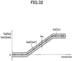
- the first execution judgment means comprises actual turning index computation means for computing, on the basis of the actual turning state quantity (Ta), an actual turning index (Sa) representing the degree of actual turning of the vehicle; and calculative turning index computation means for calculating a calculative turning index (Se) corresponding to the actual turning index (Sa) on the basis of the position (Pvh) of the vehicle and the curve information (Rc, Pc), wherein the first execution judgment means performs the above-described determination on the basis of the result of comparison between the actual turning index (Sa) and the calculative turning index (Se).
- the reliability of the curve information can be evaluated on the basis of the result of the comparison between the calculative turning index computed on the basis of the map information and the actually detected actual turning index. Specifically, when the actual turning index and the calculative turning index approximately coincide with each other (when the difference is equal to or less than a predetermined value), the reliability of the curve information is considered to be high. Therefore, the determination result can be set to the enabled state. Meanwhile, when the difference between the actual turning index and the calculative turning index is large (when the difference is in excess of the predetermined value), the reliability of the curve information is considered to be low. Therefore, the determination result can be set to the disabled state.
- the first execution judgment means comprises steering characteristic computation means for computing, on the basis of the actual turning state quantity (Ta), a steering characteristic value (Sch, ⁇ Yr) representing a steering characteristic of the vehicle, wherein the first execution judgment means performs the above-described determination of the basis of the steering characteristic value (Sch, ⁇ Yr).
- the steering characteristic value is a deviation between an actual turning state quantity and a target turning state quantity computed on the bases of the speed of the vehicle and a steering wheel angle.
- a point at which start of the deceleration control is requested after the vehicle has entered the curve is located before and near the start point of a constant curvature radius section of the curve in which the radius of curvature becomes small.
- the vehicle tends to exhibit a steering characteristic of under steering, the degree of which is however lower than a level above which vehicle stabilization control must be performed.
- the steering characteristic value assumes a large value.
- the following action can be realized.
- the possibility of the vehicle actually traveling in the curve is judged to be low (accordingly, the reliability of the curve information is low), and the determination result can be set to the disabled state.
- the steering characteristic value is large (equal to or greater than the predetermined value)
- the vehicle exhibits under steering, and the possibility of the vehicle actually traveling in the curve is judged to be high (accordingly, the reliability of the curve information is high)
- the determination result can be set to the enabled state.
- the traveling control apparatus may comprise stabilization control means for executing stabilization control for stabilizing the turning state of the vehicle on the basis of the steering characteristic value (Sch, ⁇ Yr), wherein the first execution judgment means sets the determination result to the disabled state when the steering characteristic value (Sch, ⁇ Yr) is less than a (previously set) first predetermined value (Sc1), and changes the determination result from the disabled state to the enabled state when the steering characteristic value (Sch, ⁇ Yr) changes from a value less than the first predetermined value (Sc1) to the first predetermined value (Sc1) or greater; and the stabilization control means starts the stabilization control when the steering characteristic value (Sch, ⁇ Yr) exceeds a (previously set) second predetermined value (Sc2) greater than the first predetermined value (Sc1).
- the first execution judgment means sets the determination result to the disabled state when the steering characteristic value (Sch, ⁇ Yr) is less than a (previously set) first predetermined value (Sc1), and changes the determination result from the disabled state
- the deceleration control in a process in which the degree of under steering (accordingly, the steering characteristic value) is increasing after the vehicle has entered the curve, the deceleration control is first started.
- the stabilization control is not started.
- the stabilization control is started and executed. Since the deceleration control is started and executed earlier than and preferentially over the stabilization control, it is possible to prevent the stabilization control from unnecessarily being started.
- the first execution judgment means may be configured to perform the above-described determination on the basis of a change in the result (Sh) of the above-mentioned comparison up to a point in time when at least one of the actual turning index (Sa) and the calculative turning index (Se) (zero when the vehicle enters the curve (in a straight traveling state) reaches a predetermined value (Ths).
- the first execution judgment means may be configured to bring the determination result into the enabled state when a state in which the difference (Sh) between the actual turning index (Sa) and the calculative turning index (Se) is equal to or less than a predetermined value (Sh1) continues over a predetermined range (Ls1, Ts1) (after when the vehicle has entered the curve (a point on map or a point in time)).
- both the values of the actual turning index and the calculative turning index are small because of a large curvature radius of the curve. Accordingly, if the above-mentioned determination is executed immediately after the vehicle has entered the curve, the determination result is set on the basis of the result of mutual comparison between small values, whereby the reliability of the determination result decreases.
- the above-mentioned determination is not executed immediately after the vehicle has entered the curve, and is executed after the vehicle travels within the curve for a short while after having entered the curve (that is, in a stage in which both the values of the actual turning index and the calculative turning index become relatively large due to a decrease in the curvature radius). Accordingly, the determination result is set on the basis of the result of mutual comparison between relatively large values, whereby the reliability of the determination result can be increased.
- the above-mentioned determination is made while the vehicle is traveling in the approaching transition curve section (Zci) of the curve, and, when the determination result is set to the enabled state, the deceleration control can be started while the vehicle is traveling within the approaching transition curve section (Zci).
- the above-mentioned determination is made in the first half of the approaching transition curve section, and, when the determination result is set to the enabled state (the reliability of the curve information is high), the deceleration control is started immediately.
- the determination result is set to the disabled state (when the reliability of the curve information is low due to renovation of a road or the like), the deceleration control is not started.
- the calculative turning index computation means is configured to judge a relation (Rch) between position within the curve and curvature radius of the curve on the basis of the curve information (Rc, Pc), compute the curvature radius (Rvh) of the curve at the position (Pvh) of the vehicle on the basis of the judged relation and the position (Pvh) of the vehicle, and compute the calculative turning index (Se) on the basis of the computed curvature radius (Rvh).
- the calculative turning index which can change every moment, can be computed stably and accurately on the basis of the curvature radius of the curve at the vehicle position, which changes every moment.
- the actual turning state quantity acquisition means acquires an actual steering angle ( ⁇ fa, ⁇ swa) of the vehicle as the actual turning state quantity (Ta)
- the actual turning index computation means uses the actual steering angle ( ⁇ fa, ⁇ swa) as the actual turning index (Sa) (accordingly, uses a calculated value of the steering angle as the calculative turning index).
- the predetermined value can be set to a constant value (fixed value).
- the actual turning state quantity acquisition means obtains two or more actual turning state quantities (Ta) (two or more types of actual turning state quantities (Ta) having different dimensions), the actual turning index computation means computes the actual turning index (Sa) on the basis of the two or more actual turning state quantities (Ta), and the calculative turning index computation means computes, on the basis of the position (Pvh) of the vehicle and the curve information (Rc, Pc), two or more calculative turning state quantities (Te) (two or more types of calculative turning state quantities (Te) having different dimensions) corresponding to the actual turning state quantities, and computes the calculative turning index (Se) corresponding to the actual turning index (Sa) on the basis of the two or more calculative turning state quantities (Te).
- the above-mentioned determination is executed on the basis of the result of comparison between the calculative turning index and the actual turning index obtained on the basis of the two or more turning state quantities (two or more types of turning state quantities having different dimensions). Accordingly, the redundancy of the deceleration control is improved.
- the vehicle speed control means comprises wheel brake control means for controlling a braking torque applied to wheels of the vehicle, wherein the wheel brake control means controls the braking torque such that a changing gradient of the braking torque with respect to time does not exceed a predetermined value (Lwc, Lwd).
- the deceleration control when the determination result is switched from the disabled state to the enabled state in a state in which the deceleration control is not executed, the deceleration control may be started suddenly. Similarly, when the determination result is switched from the enabled state to the disabled state in a state in which the deceleration control is being executed, the deceleration control may be interrupted suddenly. According to the above-described configuration, it is possible to prevent the deceleration of the vehicle from changing suddenly due to such start and interruption of the deceleration control.
- the first execution judgment means comprises storage means for storing a curve for which the determination result of the first execution judgment means was set to the disabled state, wherein, when the vehicle travels through the stored curve again, the determination result is set to the disabled state.
- the above-described traveling control apparatus comprises second execution judgment means which differs from the first execution judgment means and which judges, on the basis of the actual turning state quantity (Ta), whether execution of the deceleration control is to be permitted or prohibited and for outputting as a result of the determination, an output which is brought into an enabled state in which execution of the deceleration control is enabled or a disabled state in which execution of the deceleration control is disabled, wherein the vehicle speed control means executes the deceleration control when the determination result of the first execution judgment means is in the enabled state, and the determination result of the second execution judgment means is in the enabled state.
- Ta actual turning state quantity
- the determination as to whether execution of the deceleration control is to be permitted or prohibited is performed on the basis of two types of different determination results. Accordingly, as compared with the case where the determination as to whether execution of the deceleration control is to be permitted or prohibited is performed on the basis of one determination result, the deceleration control within the curve can be executed on the basis of curve information having a higher reliability only.
- an apparatus for evaluating the reliability of the curve information comprises vehicle position acquisition means for acquiring a position (Pvh) of the vehicle; curve information acquisition means for acquiring curve information (Rc, Pc) of a road on which the vehicle is traveling; actual turning state quantity acquisition means for acquiring a actual turning state quantity (Ta) representing an actual turning state of the vehicle; actual turning index computation means for computing, on the basis of the actual turning state quantity (Ta), an actual turning index (Sa) representing the degree of actual turning of the vehicle; calculative turning index computation means for computing, on the basis of the position (Pvh) of the vehicle and the curve information (Rc, Pc), a calculative turning index (Se) corresponding to the actual turning index (Sa); and reliability computation means for computing a reliability (S
- the reliability of the curve information obtained in this manner can be used for reporting to a driver, which is performed by making use of the curve information, vehicle traveling control, which is performed by making use of the curve information, or the like.
- the traveling control apparatus for a vehicle can be described to be an apparatus which comprises vehicle position acquisition means for acquiring a position of the vehicle; curve information acquisition means for acquiring information of a curve of a road on which the vehicle is traveling; vehicle speed acquisition means for acquiring a speed of the vehicle; deceleration control means for executing deceleration control which decreases the speed of the vehicle when the vehicle passes through the curve, on the basis of the position of the vehicle, the curve information, and the speed of the vehicle; and actual turning state quantity acquisition means for acquiring an actual turning state quantity which represents an actual turning state of the vehicle, wherein the deceleration control means executes the deceleration control on the basis of the actual turning state quantity.
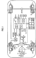
- FIG. 1 schematically shows the structure of a vehicle on which the traveling control apparatus according to a first embodiment of the present invention (hereinafter referred to as the "present apparatus") is mounted.
- the present apparatus includes an engine EG, which is a power source of the vehicle, an automatic transmission TM, a brake actuator BRK, an electronic control unit ECU, and a navigation apparatus NAV.
- the engine EG is an internal combustion engine.
- a throttle actuator TH adjusts the opening of a throttle valve TV in response to operation of an accelerator pedal (accelerating operation member) AP by a driver.
- a fuel injection actuator FI injects fuel in an amount in proportion to the intake air amount adjusted in accordance with the opening of the throttle valve TV.
- the engine EG outputs an output torque corresponding to the amount of operation of the accelerator pedal AP by the driver.
- the automatic transmission TM is a multi-stage automatic transmission having a plurality of gear stages or a non-stage automatic transmission having no gear stage.
- the brake actuator BRK has a known structure, and includes a plurality of solenoid valves, a hydraulic pump, a motor, etc.
- the brake actuator BRK supplies wheel cylinders WC** of wheels WH** with brake pressure (brake hydraulic pressure) corresponding to an operation of a brake pedal BP (brake operation member) by the driver.
- the brake actuator BRK can individually adjust the braking pressures within the wheel cylinders WC** independently of the operation of the brake pedal BP (and the operation of the accelerator pedal AP).
- wheel cylinders WC** collectively represent the front left wheel cylinder WCfl, the front right wheel cylinder WCfr, the rear left wheel cylinder WCrl, and the rear right wheel cylinder WCrr.
- the present apparatus includes wheel speed sensors WS** for detecting wheel speeds Vw** of the wheels WH**; brake pressure sensors PW** for detecting brake pressures within the wheel cylinders WC**; a steering wheel angle sensor SA for detecting rotation angle of the steering wheel SW (from its neutral position); a front wheel steering angle sensor FS for deterring steering angle of the front wheels; a yaw rate sensor YR for detecting yaw rate of the vehicle body; a longitudinal acceleration sensor GX for detecting acceleration (deceleration) in a front-rear direction of the vehicle body (hereinafter referred to as the " longitudinal direction); a lateral acceleration sensor GY for detecting acceleration in the lateral direction of the vehicle body; an engine speed sensor NE for detecting rotational speed of the output shaft of the engine EG; an accelerating operation amount sensor AS for detecting the amount of operation of the accelerator pedal (accelerating operation member) AP; a brake operation amount sensor BS for detecting the amount of operation of the brake pedal BP; a shift position sensor
- the self aligning torque sensor ATf* is fixed to, for example, the wheel rim of each steerable wheel, and detects distortion of the wheel rim.
- the self aligning torque sensor ATf* detects the self aligning torque on the basis of information regarding the deformation and the position of the wheel rim whose distortion is detected.
- the electronic control unit ECU is a microcomputer for electronically controlling a power train system and a chassis system.
- the electronic control unit ECU is electrically connected to, or can communicate through a network with, the above-described various actuators, the above-described various sensors, and the automatic transmission TM.
- the electronic control unit ECU is composed of a plurality of control units (ECU1 to ECU4) connected together via a communication bus CB.
- the ECU1 within the electronic control unit ECU is a wheel brake control unit that controls the brake actuator BRK on the basis of signals from the wheel speed sensors WS**, the longitudinal acceleration sensor GX, the lateral acceleration sensor GY, the yaw rate sensor YR, etc., to thereby execute brake pressure control (wheel brake control), such as vehicle stabilization control (ESC control), antiskid control (ABS control), and traction control (TCS control), which are well known. Furthermore, the ECU1 computes the speed of the vehicle (vehicle speed) Vx from the wheel speeds Vw** detected by the wheel speed sensors WS**.
- brake control wheel brake control
- ESC control vehicle stabilization control
- ABS control antiskid control
- TCS control traction control
- the ECU2 within the electronic control unit ECU is an engine control unit that controls the throttle actuator TH and the fuel injection actuator FI on the basis of signals from the accelerating operation amount sensor AS, etc., to thereby control the output torque of the engine EG (engine control).
- the ECU3 within the electronic control unit ECU is an automatic transmission control unit that controls the automatic transmission TM on the basis of signals from the shift position sensor HS, etc., to thereby execute reduction ratio control (transmission control).
- the ECU4 within the electronic control unit ECU is an electronic power steering control unit that controls an electronic power steering apparatus EPS on the basis of signals from the steering torque sensor ST, etc., to thereby execute power steering control.
- the navigation apparatus NAV includes a navigation processing apparatus PRC, which is electrically connected to vehicle position detection means (a global positioning system) GPS, a yaw rate gyro GYR, an input section INP, a storage section MAP, and a display section (display) MTR.
- vehicle position detection means a global positioning system
- gyro GYR vehicle position detection means
- INP input section
- storage section MAP storage section
- display section (display) MTR display section
- the navigation apparatus NAV is electrically connected to, or can communicate wireless with, the electronic control unit ECU.
- the vehicle position detection means GPS can detect the position (latitude, longitude, etc.) of the vehicle by one of well known methods utilizing positioning signals from satellites.
- the yaw rate gyro GYR can detect angular speed (yaw rate) of the vehicle body.
- the input section INP receives driver's operations associated with navigation functions.
- the storage section MAP stores various pieces of information, such as map information and road information.
- the navigation processing apparatus PRC comprehensively processes the signals from the vehicle position detection means GPS, the yaw rate gyro GYR, the input section INP, and the storage section MAP, and displays the processing results (information related to the navigation function) on the display section MTR.
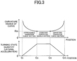
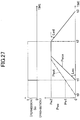
- the (single) curve shown in FIG. 2 is composed of an approaching transition curve section Zci (in which the radius curvature decreases gradually with traveling of the vehicle), a constant curvature radius section Zit, and a departing transition curve section Zcd (in which the radius curvature increases gradually with traveling of the vehicle), in this sequence, from a curve start point Ci (curve entrance) toward a curve end point Cd (curve exit).
- Each of the transition curves is composed of, for example, a clothoid curve.
- the transition curve sections are provided in order to enable the vehicle to smoothly pass through the curve through a driver's operation of gradually rotating a steering wheel and then gradually returning the steering wheel to its neutral position, without requiring the driver to rapidly rotate the steering wheel.
- the radius of curvature is infinite at the curve start point Ci (that is, the end point of a straight road section), then decreases gradually, and becomes Rm (the minimum radius of curvature within the curve) at the start point Cs of the constant curvature radius section Zit. After that, the radius of curvature is maintained at Rm up to the end point Ce of the constant curvature radius section Zit, then increases gradually, and becomes infinite at the curve end point Cd (that is, the start point of the next straight road section).
- the turning state quantity (e.g., lateral acceleration) starts to increase from "0 (straight traveling)" at the curve start point Ci, increases generally proportionally in the approaching transition curve section Zci, and assumes a constant value (maximum value) in the constant curvature radius section Zit. After that, the turning state quantity decreases generally proportionally in the departing transition curve section Zcd, and becomes "0 (straight traveling)" at the curve end point Cd.
- deceleration control which decelerates the vehicle in a curve becomes necessary at a point before and near the start point Cs of the constant curvature radius section Zit of the curve in which the radius of curvature becomes small.
- the vehicle tends to exhibit a steering characteristic of under steering, the degree of which is however lower than a level above which "stabilization control” which stabilizes the turning state of the vehicle must be performed.
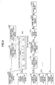
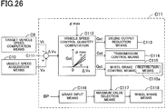
- curve information acquisition means A1 acquires pieces of information Rc, Pc (position Pc and curve curvature radius Rc at that position) regarding a curve located ahead of the vehicle.
- the curve information Rc, Pc is stored in a map information database of the storage section MAP.
- a position Pc e.g., information representing the latitude and longitude of that position
- the curvature radius Rc of the curve at that position Pc are directly stored.
- a form e.g., an arithmetic expression and coefficients which can compute the position Pc and the curvature radius Rc may be stored as the curve information.
- Vehicle position acquisition means A2 acquires the present position Pvh of the vehicle.
- the vehicle position Pvh is detected by use of the global positioning system GPS.
- Target vehicle speed computation means A3 computes, on the basis of the curve information Rc, Pc and the vehicle position Pvh, a target vehicle speed Vt at which the vehicle can stably pass through a curve under consideration.
- the “prohibition state” is also called a “disabling state,” and means a state in which the function of the deceleration control executed by the wheel brake control unit ECU1 within the electronic control unit ECU is disabled (this state will be referred to as the “disabled sate”).
- “O” is output as a control quantity (target quantity) for the deceleration control.
- the “permission state” is also called an “enabling state,” and means a state in which the function of the deceleration control is enabled (this state will be referred to as the “enabled sate”).
- the control quantity (target quantity) for the deceleration control is output as is.
- Actual turning state quantity acquisition means A6 acquires an actual yaw motion state quantity (actual turning state quantity Ta) of the vehicle.
- the actual turning state quantity Ta is a yawing motion state quantity actually generated in the vehicle.
- Examples of the actual turning state quantity Ta include actual yaw rate Yr, actual lateral acceleration Gy, actual vehicle body slip angle ⁇ a, and actual vehicle body slip angular velocity d ⁇ a.
- a value obtained by combining two or more of the above-mentioned state quantities may be used as the actual turning state quantity Ta.
- Target turning state quantity acquisition means A7 acquires a target yaw motion state quantity (target turning state quantity Td) of the vehicle.
- a value of the same dimension corresponding to the actual turning state quantity Ta is computed as the target turning state quantity Td.
- the target turning state quantity Td is computed on the basis of the vehicle speed Vx and the steering wheel angle ⁇ sw (or the front wheel steering angle ⁇ f).
- Steering characteristic computation means A8 computes the steering characteristic of the vehicle (under steering, neutral steering, over steering) on the basis of the actual turning state quantity Ta and the target turning state quantity Td, and outputs the computation result (steering characteristic value) Sch.
- the steering characteristic value Sch is a value which represents the steering characteristic of the vehicle.
- the steering characteristic value Sch is computed to have a large positive value.
- the steering characteristic can be computed on the basis of the actual turning state quantity Ta only without use of the target turning state quantity Td.
- the steering characteristic value Sch can be computed on the basis of the actual vehicle body slip angular velocity d ⁇ a, the actual vehicle body slip angle ⁇ a, etc.
- Execution judgment means A9 decides, on the basis of the steering characteristic value Sch, the result of determination as to whether execution of the deceleration control is to be permitted or prohibited, and outputs the determination result (control flag) So.
- the execution judgment means A9 may perform final determination as to whether execution of the deceleration control is to be permitted or prohibited, on the basis of not only the determination result (control flag) So based on the steering characteristic value Sch, but also other determination results (control flags Sy, Sd, Ss, Sm). These will be described later. First, description will be continued for the case where the execution judgment means A9 performs the final determination on the basis of the determination result (control flag) So only.
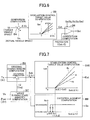
- the predetermined value Sc1 is a threshold for determining whether or not the vehicle is in the tendency of under steering. This determination is made on the basis of the thought that "in a stage in which the steering characteristic value is large, the probability that the vehicle is in the tendency of under steering and actually travels in a curve may be high (accordingly, the reliability of the curve information may be high)." As a result, the value computed through comparison between the target vehicle speed Vt and the vehicle speed Vx is output as is to the target value adjustment means A11 as the deceleration control target value Gst.
- Stabilization control target value computation means A10 computes a target value Est for stabilization control (a target value for wheel braking, and a target value for braking torque) on the basis of the steering characteristic value Sch.
- Stabilization control is a well known control for suppressing under steering and over steering of the vehicle.
- Target value adjustment means A11 adjusts the deceleration control target value Gst and the stabilization control target value Est, and computes a braking control target value Bt.
- the condition for starting the stabilization control is Sch > Sc2 (predetermined value).
- Sc2 > Sc1. Therefore, when Sch ⁇ Sc1, none of the deceleration control and the stabilization control is executed. Therefore, "0 (non-execution of control)" is output to wheel brake control means A12 as the braking control target value Bt.
- Sc1 ⁇ Sch ⁇ Sc2 only the deceleration control can be executed. Therefore, the deceleration control target value Gst is output to the wheel brake control means A12 as the braking control target value Bt.
- the wheel brake control means A12 controls an actual braking control quantity (e.g., braking pressure) Ba on the basis of the braking control target value Bt.
- an actual braking control quantity e.g., braking pressure
- publicly known means composed of a pump, an electric motor, solenoid valves, etc. can be used as the wheel brake control means A12.
- This actual braking control quantity (e.g., braking pressure) Ba is output to wheel brake means A13, whereby braking forces are applied to the wheels.
- Publicly known means composed of a caliper, a rotor, pads, etc. can be used as the wheel brake means A13.
- the execution judgment means A9 may perform the final determination on the basis of not only the determination result (control flag) So based on the steering characteristic value Sch, but also other determination results (control flag Sy, Sd, Ss, Sm).
- a proper vehicle speed Vqo at which the vehicle can properly pass through the curve is computed.
- the curvature radius Rm of a section of the curve in which the radius of curvature becomes constant (the constant curvature radius section Zit) is judged on the basis of the curve information Rc, Pc, and the proper vehicle speed Vqo is computed on the basis of the curvature radius Rm.
- the minimum curvature radius within the curve may be used as the curvature radius Rm.
- the greater the curvature radius Rm the greater the computed value of the proper vehicle speed Vqo.
- the proper vehicle speed Vqo is judged so that the vehicle can pass through the curve with a generally constant lateral acceleration, irrespective of the curvature radius Rm.
- the proper vehicle speed Vqo may be adjusted on the basis of at least one of uphill/downhill grade Kud, road width Wrd, front visibility Msk, and vehicle speed Vx.
- the proper vehicle speed Vqo is adjusted to a smaller value as compared with the case where the road is horizontal.
- the proper vehicle speed Vqo is adjusted to a larger value as compared with the case where the road is horizontal.
- the road width Wrd is small, the proper vehicle speed Vqo is adjusted to a smaller value as compared with the case where the road width Wrd is large.
- the proper vehicle speed Vqo is adjusted to a larger value as compared with the case where the road width Wrd is small.
- the proper vehicle speed Vqo is adjusted to a smaller value as compared with the case where the visibility Msk is good.
- the proper vehicle speed Vqo is adjusted to a larger value as compared with the case where the visibility Msk is poor.
- the vehicle speed Vx is high, the proper vehicle speed Vqo is adjusted to a smaller value as compared with the case where the vehicle speed Vx is low.
- the proper vehicle speed Vqo is adjusted to a larger value as compared with the case where the vehicle speed Vx is high.
- the proper vehicle speed Vqo may be adjusted on the basis of road surface friction coefficient ⁇ max. In this case, when the road surface friction coefficient ⁇ max is large, the proper vehicle speed Vqo is adjusted to a larger value as compared with the case where the road surface friction coefficient ⁇ max is small. When the road surface friction coefficient ⁇ max is small, the proper vehicle speed Vqo is adjusted to a smaller value as compared with the case where the road surface friction coefficient ⁇ max is large.
- Computation of the road surface friction coefficient ⁇ max is performed on the basis of the self aligning torque Sat of the wheels obtained by the self aligning torque sensor ATf*.
- the self aligning torque Sat also increases.
- the self aligning torque Sat reaches the maximum value before the vehicle enters a state in which the lateral forces become saturated (that is, a turning limit state). Therefore, the road surface friction coefficient ⁇ max can be estimated before the turning of the vehicle reaches the limit.
- a reference point Pcr is judged.
- the reference point Pcr refers to a target point before which the vehicle speed is decreased to the proper vehicle speed Vqo by means of the deceleration control.
- the reference point Pcr can be set at the entrance point Cs of the curve at which the radius of curvature becomes constant (a point within the constant curvature radius section closest to the vehicle).
- the point Cs within the curve at which the radius of curvature becomes the minimum may be set as the reference point Pcr.
- the point Cs is judged on the basis of the curve shape Rc and the curve position Pc.
- the point Pcr can be set such that it coincides with the entrance point Cs of the constant curvature radius section or a point shifted toward the vehicle from the point of the minimum radius of curvature by a distance Lpr (in the vicinity of an end portion of a transition curve corresponding to an approaching portion to the curve closer to the vehicle).
- the distance Lpr may be a constant value.
- the distance Lpr may be computed in accordance with the vehicle speed Vx.
- the distance Lpr is set to "0" (that is, the point Pcr coincides with Cs); and, when Vx > V1 (predetermined value), the distance Lpr is set to increase from "0" with an increase in the vehicle speed Vx from V1.
- the distance Lpr may be judged by use of the proper vehicle speed Vqo in place of the vehicle speed Vx.
- the point Pcr is set such that it coincides with a point on the curve shifted from the point Cs toward the curve start point Ci by the distance Lpr. That is, the point Pcr is set on the basis of the distance Lpr, the curve shape Rc, and the point Cs (curve position Pc).
- the point Pcr is a target point which is used to decrease the vehicle speed to the proper vehicle speed Vqo.
- the map information, etc. contain errors. Such errors can be eliminated by means of setting the point Pcr such that it coincides with a point shifted from the point Cs toward the curve entrance Ci by the distance Lpr. That is, within the curve, the vehicle speed control is started a little early, whereby the vehicle speed can be decreased to the proper vehicle speed Vqo without fail at a point on the curve shifted from the point Pcr toward the curve entrance Ci.
- a target vehicle speed computation block B3 the target vehicle speed Vt is computed.
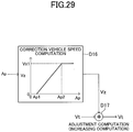
- a target vehicle speed computation characteristic Vtch for determining the target vehicle speed Vt at the vehicle position Pvh (Vt[Pvh]) is judged on the basis of the reference point Pcr and the proper vehicle speed Vqo.
- the judged target vehicle speed computation characteristic Vtch is such that the vehicle speed decreases at a deceleration Gm (e.g., a previously set constant) from the curve entrance to the reference point Pcr, and becomes the proper vehicle speed Vqo at the reference point Pcr.
- the deceleration Gm may be set to a value judged in consideration of a typical friction coefficient of wet road surface.
- the deceleration Gm can be adjusted on the basis of the road surface friction coefficient ⁇ max. Specifically, the deceleration Gm is adjusted such that the greater the road surface friction coefficient ⁇ max, the greater the value of the deceleration Gm.
- the target vehicle speed Vt at the vehicle position Pvh is computed by means of inputting the vehicle position Pvh into the target vehicle speed computation characteristic Vtch, judged on the basis of the reference point Pcr and the proper vehicle speed Vqo.
- the target vehicle speed Vt computed in this manner is output to the deceleration control target value computation means A4 (see FIG. 4 ).
- the deceleration control target value Gst is computed on the basis of the vehicle speed deviation ⁇ Vx. Specifically, the deceleration control target value Gst is computed such that the greater the deviation ⁇ Vx (> 0), the greater the computed deceleration control target value Gst, and such that, when the deviation ⁇ Vx is negative, the deceleration control target value Gst becomes "0.” That is, when the vehicle speed Vx is greater than the target vehicle speed Vt (Vx > Vt), the deceleration control is executed; and, when the vehicle speed Vx is smaller than the target vehicle speed Vt (Vx ⁇ Vt), the deceleration control is not executed.
- the deceleration control target value Gst can be adjusted on the basis of the road surface friction coefficient ⁇ max. Specifically, the deceleration control target value Gst is adjusted such that the greater the road surface friction coefficient ⁇ max, the greater the value to which the deceleration control target value Gst is adjusted.
- the deceleration control target value Gst computed in the block B5 as described above is output to a changeover computation block B6.
- the changeover computation block B6 one of the deceleration control target value Gst output from the block B5 and a target value "0" which represents prohibition of the deceleration control is selected on the basis of the determination result (control flag) So output from the execution judgment means A9.
- the deceleration control target value Gst computed in the block B5 is output as is as the final deceleration control target value Gst.
- the final deceleration control target value Gst computed/selected in this manner is output to the target value adjustment means A11 (see FIG. 4 ).
- the execution judgment means A9 performs the final determination on the basis of not only the determination result (control flag) So based on the steering characteristic value Sch, but also other determination results (control flags Sy, Sd, Ss, and Sm, which will be described later), in the changeover computation block B6, the final deceleration control target value Gst is computed/selected on the basis of the final determination result of the execution judgment means A9.
- a target yawing motion state quantity (target turning state quantity) Td of the vehicle is computed.
- a physical quantity of the same dimension corresponding to an actually generated yawing motion state quantity (actual turning state quantity) Ta is computed as the target turning state quantity Td.
- the turning state quantity is yaw rate
- a target yaw rate Yrd is computed as the target turning state quantity Td.
- the target yaw rate Yrd is computed by the following expression.
- Kh is a stability factor
- L is a wheel base of the vehicle
- SG is a steering gear ratio of the vehicle.
- a steering characteristic computation block B8 the target turning state quantity Td is compared with the actual turning state quantity Ta of the same dimension corresponding to the target turning state quantity Td, whereby the steering characteristic of the vehicle is computed.
- the steering characteristic value Sch is computed by making use of the yaw rate
- the steering characteristic is as follows. When the yaw rate deviation ⁇ Yr is approximately "0," the vehicle exhibits neutral steering. When ⁇ Yr ⁇ 0, the vehicle exhibits over steering, and the degree of the over steering increases with the absolute value of the deviation ⁇ Yr. When ⁇ Yr > 0, the vehicle exhibits under steering, and the degree of the under steering increases with the deviation ⁇ Yr.
- an execution judgment computation block B9 a determination is made as to whether execution of the deceleration control is to be permitted or prohibited.
- the predetermined value Sc1 is set to be smaller than a predetermined value Sc2, which will be described later.
- the stabilization control target value Est is computed on the basis of the steering characteristic value Sch (or the yaw rate deviation ⁇ Yr). Specifically, when the steering characteristic value Sch (or the yaw rate deviation ⁇ Yr) is equal to or smaller than the (previously set) predetermined value Sc2, the stabilization control target value Est is computed to be "0.” That is, a relation Sch > Sc2 is a condition for starting the stabilization control.
- the stabilization control target value Est is individually judged for each wheel so as to maintain a proper steering characteristic, while suppressing excessive under steering or excessive over steering of the vehicle.
- “fo” represents the stabilization control target value Est for a front wheel located on the outer side of a turning locus
- “ro” represents that for a rear wheel located on the outer side of the turning locus
- “ri” represents that for a rear wheel located on the inner side of the turning locus.
- the predetermined value Sc2 is set to be greater than the predetermined value Sc1. Accordingly, in a process in which the steering characteristic is changing from neutral steering to under steering (accordingly, Sch is increasing) after the vehicle has entered the curve (in a period in which the vehicle is traveling in the approaching transition curve section Zci), first, the deceleration control can be started. In the case where the under steering is eliminated through execution of the deceleration control, the stabilization control is not started. Meanwhile, in the case where the under steering is not eliminated through execution of the deceleration control, the stabilization control is started and executed. Since the deceleration control is started and executed earlier than and preferentially over the stabilization control, it is possible to prevent the stabilization control from unnecessarily being started.
- Target value adjustment means B11 adjusts the deceleration control target value Gst and the stabilization control target value Est to thereby judge the braking control target value Bt.
- the braking control target value Bt is computed by means of "increasing computation”; i.e., adding the stabilization control target value Est to the deceleration control target value Gst.
- the deceleration control target value Gst and the stabilization control target value Est are adjusted by means of "selection computation.”
- a value obtained by means of "decreasing computation”; i.e., subtracting the stabilization control target value Est from the deceleration control target value Gst is output to the wheel brake control means A12 as the braking control target value Bt.
- the wheel brake control means A12 controls the actual braking torque Ba (braking pressure) applied to the wheel brake means A13 on the basis of the braking control target value Bt.
- the wheel brake control means A12 when the actual braking torque Ba is controlled, an amount Bp by which the driver operates a brake operation member is taken into consideration.
- braking torque time gradient restriction means imposes a restriction on the changing gradient of the braking torque with respect to time. Specifically, the increase gradient of Ba with respect to time is restricted to a predetermined value Lwc, and the decrease gradient of Ba with respect to time is restricted to a predetermined value Lwd.
- the deceleration control may be executed by making use of deceleration, which can be adjusted by use of down shift of the automatic transmission TM, in place of wheel braking.
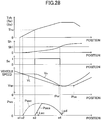
- ⁇ Vx > 0 that is, the deceleration control start condition is satisfied
- the deceleration control target value Gst is maintained at "0.” That is, the deceleration control is not started, and the actual braking torque (braking pressure) Ba is also maintained at "0.”
- the time gradient restriction Lwc is imposed on increase of the braking torque. Therefore, even when the deceleration control is started suddenly, the actual braking torque (braking pressure) Ba does not increase sharply, and the vehicle is not decelerated sharply.
- the steering characteristic value Sch becomes smaller than the predetermined value Sc0 ( ⁇ the predetermined value Sc1).
- the time gradient restriction Lwd is imposed on decrease of the braking torque. Therefore, even when the deceleration control is ended suddenly, the actual braking torque (braking pressure) Ba does not decrease sharply, and the vehicle deceleration does not decreases sharply.
- the deceleration control is started when the steering characteristic value Sch reaches a value indicating the tendency of under steering, as a result of the curvature radius Rc of the curve decreasing gradually after the vehicle has entered the curve. Accordingly, the deceleration control is not executed in the case where the steering characteristic value Sch does not reach the value indicating the tendency of under steering, because the shape of the curve is changed by renovation or the like of the road (e.g., a curved section is changed to a straight section). That is, the deceleration control is prevented from being unnecessarily started and executed on the basis of curve information whose reliability is low.
- the deceleration control can be executed on the basis of only curve information whose reliability is sufficiently high. In other words, it is possible to prevent the deceleration control from unnecessarily being started and executed on the basis of curve information which is low in reliability.
- the deceleration control which should not be started, can be prohibited from being started.
- a point at which start of the deceleration control is requested after the vehicle has entered the curve is a point before and near the start point Cs of the constant curvature radius section Zit of the curve where the radius of curvature decreases. Accordingly, by means of setting the predetermined value Sc1 to a value similar to the steering characteristic value Sch at the time when the vehicle passes through this point, the point at which the deceleration control is started can be made a proper point.
- the execution judgment means A9 makes the final determination on the basis of only the determination result (control flag) So based on the steering characteristic value Sch.
- the embodiment may be modified such that the execution judgment means A9 makes the final determination; i.e., outputs the final determination result (control flag Sfin) on the basis of not only the determination result (control flag) So based on Sch, but also other determination results (control flags Sy, Sd, Ss, Sm).
- control flag Sfin When the control flag Sfin is "1," it represents that the final determination result of the execution judgment means A9 is the permission state (the state in which execution of the deceleration control is permitted). When the control flag Sfin is "0,” it represents that the final determination result of the execution judgment means A9 is the prohibition (the state in which execution of the deceleration control is prohibited). In this case, the operation can be described by replacing “So” with "Sfin” in FIGS. 4 and 6 .
- the "prohibition state” corresponds to the "disabled state”
- the "permission state” corresponds to the "enabled state.”
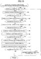
- a routine corresponding to this flowchart is repeatedly executed at predetermined intervals (e.g., 6 msec).
- the heading angle Ya refers to an angle of the traveling direction of the vehicle (a direction which the vehicle faces) at the vehicle position, in relation to the direction of the straight section before the curve entrance.
- the "direction of the straight section before the curve entrance” can be judged as follows, for example.
- a straight section is judged on the basis of changes in the actual turning state quantity within a section of a predetermined distance (e.g., 20 m) through which the vehicle has traveled, and the traveling direction of the vehicle in the judged straight section is recorded as the direction of the straight section before the curve entrance.
- the predetermined distance is judged in such a manner as to absorb an error of the position of the curve entrance Ci judged on the basis of the map information stored in the storage section MAP, an error of the vehicle position Pvh obtained by use of the global positioning system GPS or the like, and other errors.
- the heading angle Ya is computed on the basis of the actual turning state quantity Ta (e.g., the actual yaw rate Yr).
- the actual yaw rate Yr is acquired as the actual turning state quantity Ta, and the actual yaw rate Yr is integrated (added up) from the curve entrance Ci, whereby the heading angle (yaw angle) Ya is computed.
- a heading angle Ya2 at the curve exit Cd (or the end point Ce of the constant curvature radius section) is computed on the basis of the curve information Rc, Pc.
- the heading angle Ya2 is the angle of the tangential direction of the curve at the curve exit Cd (or the point Ce) in relation to the direction of the straight section before the curve entrance.
- a predetermined value Ya1 is computed on the basis of the vehicle speed Vx. Specifically, the predetermined value Ya1 is computed such that the higher the vehicle speed Vx, the smaller the predetermined value Ya1.
- This determination computation is based on the thought "that, when the heading angle Ya is small (less than Ya1), the possibility of the vehicle actually traveling in the curve is low (accordingly, the reliability of the curve information is low); and, when the heading angle Ya is large (equal to or greater than Ya1), the possibility of the vehicle actually traveling in the curve is high (accordingly, the reliability of the curve information is high)."
- the heading angle Ya is a cumulative value of the actual yaw rate Yr from the curve entrance Ci. Accordingly, even in the case where the position of the vehicle in the width direction of the road changes (the vehicle staggers) after the vehicle has entered the curve, the heading angle Ya can represent the traveling direction of the vehicle as viewed macroscopically. Accordingly, even in the case where a driver takes an out-in-out traveling line, the degree of the reliability of the curve information; i.e., whether to permit or prohibit execution of the deceleration control can be judged reliably from the determination result (control flag) Sy.
- the fact that the "heading angle Ya has become equal to or greater than the predetermined value Ya1" corresponds to the fact that "turning for a curve is detected.”
- "turning for a curve” may be detected on the basis of not only the computed heading angle but also the detected values (actual values) such as the actual yaw rate and the steering wheel angle, or may be detected by use of an image capturing apparatus such as an on-board camera or a sensor such as a millimeter wave laser radar.
- "turning for a curve” is detected as follows.
- the three-dimensional object moves within a screen at a constant speed corresponding to the vehicle speed, and the position of the three-dimensional object in the screen changes. At that time, the three-dimensional object exhibits a certain motion within the screen around a vanishing point.
- the vehicle turns left or right, a three-dimensional object uniformly moves horizontally within the screen from an end of the screen. Accordingly, "turning for a curve" can be detected through detection of the fact that a three-dimensional object within the screen uniformly moves horizontally from an end of the screen.
- turning can be judged from the "positional relation between a detected object (stationary object) and the vehicle itself" and the “vehicle speed of the vehicle itself.” Specifically, when a stationary object is detected while the vehicle is turning, the stationary object moves laterally within the screen and the distance between the stationary object and the vehicle increases. Accordingly, in the case where a stationary object is detected and the detection result shows that the stationary object moves laterally within the screen after that and the distance between the stationary object and the vehicle increases, "turning for a curve" can be detected.
- a sensor in particular, millimeter wave laser radar
- the computation (processing of steps 104 and 105) of the determination result (control flag) So based on Sch is identical with that performed in the blocks B7, B8, and B9 shown in FIG. 7 .
- This determination computation is based on the thought "that, when the actual turning state quantity Ta (e.g., Gy) is small (smaller than Ta1), the possibility of the vehicle actually traveling in the curve is low (accordingly, the reliability of the curve information is low); and, when the actual turning state quantity Ta (e.g., Gy) is large (equal to or greater than Ta1), the possibility of the vehicle actually traveling in the curve is high (accordingly, the reliability of the curve information is high).
- a relation Ta0 ⁇ Ta1 is present between the predetermined values Ta0 and Ta1. By virtue of this relation, it is possible to prevent occurrence of hunting of the determination result (control flag) Ss as to whether to permit or prohibit execution of the deceleration control.
- the vehicle when the absolute value of the actual turning state quantity Ta is less than a predetermined value Ts, the vehicle is judged to be in a "straight traveling" state.
- the absolute value of the actual turning state quantity Ta is equal to or greater than the predetermined value Ts, the vehicle is judged to be turning.
- a determination as to whether the turning is "leftward turning” or “rightward turning” is made on the basis of the sign of the actual turning state quantity Ta at that time. That is, data representing one of the "straight traveling,” “leftward turning,” and “rightward turning” is computed as the turning direction Dvh.
- the curve direction Dcv in relation to the traveling direction of the vehicle is judged on the basis of the curve information Rc, Pc, and the vehicle position Pvh. Specifically, when the curve curvature radius Rvh at the vehicle position Pvh is greater than a predetermined value Rvs, the curve direction Dcv is judged to be "straight.” When the curve curvature radius Rvh is equal to or less than the predetermined value Rvs, the curve direction Dcv is judged to be "leftward curve” or “rightward curve” depending on the direction of the curve curvature radius Rvh. That is, data representing one of "straight,” “leftward curve,” and “rightward curve” is computed as the curve direction Dcv.
- This determination is based on the thought "that, when the turning direction Dvh and the curve direction Dcv coincide with each other, the reliability of the curve information is high; and, when the turning direction Dvh and the curve direction Dcv do not coincide with each other, the reliability of the curve information is low.”
- the relation (curvature radius computation characteristic) Rch between the position Pc within the curve and the curvature radius Rc is computed on the basis of the curve information Rc, Pc.
- the curvature radius computation characteristic Rch can be estimated on the basis of a curve obtained by geometrically and smoothly connecting the positions of a plurality of points (nodes) on a road, which are stored in advance (see, for example, Japanese Patent No. 3378490 ).
- the curvature radius computation characteristic Rch can be stored in the map information database by use of a function representing a transition curve (e.g., clothoid curve) and parameters or the like.
- the curve curvature radius Rvh at the vehicle position Pvh is computed on the basis of the curvature radius computation characteristic Rch. That is, by means of inputting the vehicle position Pvh to the curvature radius computation characteristic Rch defined by the relation between position and curvature radius, the curve curvature radius Rvh at the vehicle position Pvh is computed.
- a calculative turning state quantity Te is computed on the basis of the computed curvature radius Rvh.
- the following state quantities can be computed as the calculative turning state quantity Te.
- Calculative lateral acceleration Gye Vx 2 /Rvh
- Calculative yaw rate Yre Vx/Rvh
- Calculative steering angle ⁇ fe [L ⁇ (1+Kh ⁇ Vx 2 )]/Rvh
- Calculative steering wheel angle ⁇ swe [SG ⁇ L ⁇ (1+Kh ⁇ Vx 2 )]/Rvh
- Calculative wheel speed difference ⁇ Vwe (Tr ⁇ Vx)/Rvh
- Calculative heading angle Yae (the tangential direction of the curve at the vehicle position Pvh in relation to the direction of the straight section before the curve entrance)
- Kh is a stability factor
- L is the wheel base of the vehicle
- Tr is the tread of the vehicle
- SG the steering gear ratio of the vehicle.
- the calculative turning index Se is computed on the basis of the calculative turning state quantity Te.
- the curve curvature radius Rvh computed as described above can be used as is as the calculative turning index Se.
- two or more of different calculative turning indices Se computed on the basis of the above-described different calculative turning state quantities may be combined so as to compute the calculative turning index Se.
- the actual turning index Sa is computed on the basis of the actual turning state quantity Ta.
- Physical quantities (state quantities) which are identical to each other (in terms of dimension) are computed as the actual turning index Sa and the calculative turning index Se.
- the curve curvature radius Rta is computed on the basis of the actual turning state quantity Ta as the actual turning index Sa corresponding to the calculative turning index Se.
- Rta may be obtained by any of the following computations.
- Rta Vx 2 / Gya
- Rta Vx / Yra
- Rta L ⁇ 1 + Kh ⁇ Vx 2 / ⁇ ⁇ fa
- Rta SG ⁇ L ⁇ 1 + Kh ⁇ Vx 2 / ⁇ ⁇ swa
- Kh is a stability factor
- L is the wheel base of the vehicle
- SG is the steering gear ratio of the vehicle.
- a comparison computation block B26 the calculative turning index Se and the actual turning index Sa are compared.
- the absolute value of the deviation (turning index deviation) between the actual turning index Sa and the calculative turning index Se can be used as the comparison result Sh.
- the determination result (control flag) Sm is computed on the basis of the turning index deviation Sh.
- the determination as to whether the deceleration control is to be permitted or prohibited is continued after the deceleration control is started.
- a relation Sh1 ⁇ Sh2 exists between the predetermined value Sh1 and the predetermined value Sh2.
- a determination state quantity (a state quantity used for the determination as to whether execution of the deceleration control is to be permitted or prohibited).
- the predetermined values Ya1, Sc1, Ta1, Ts, Rvs, and Ths can be set to those values corresponding to the state of a curve under consideration or the turning state of the vehicle at the time when the vehicle travels along a portion of the curve between the entrance thereof and the center point of the approaching transition curve section (approaching clothoid curve section) thereof. Therefore, the determination as to whether execution of the deceleration control is to be permitted or prohibited can be completed in the first half of the approaching transition curve section of the curve under consideration.
- the vehicle speed control for decelerating the vehicle can be started in the second half of the approaching transition curve section of the same curve.
- the "prohibition state” corresponds to the "disabled state”
- the "permission state” corresponds to the " enabled state.”
- a routine corresponding to this flowchart is also repeatedly executed at predetermined intervals (e.g., 6 msec), like the routine shown in FIG. 10 .
- the routine of FIG. 15 is obtained by replacing the steps 101, 103, 105, 107, 110, 114, and 115 of the routine of FIG. 10 with steps 201, 203, 205, 207, 210, 214, and 215, respectively. In the following, only the steps of the routine of FIG. 15 which differ from the corresponding steps of FIG. 10 will be described.
- the result of the determination is "Yes”
- processing of step 215 is performed.
- the result of the determination is "No”
- processing of step 104 and subsequent steps is performed.
- the result of the determination is "Yes”
- processing of step 215 is performed.
- the result of the determination is "No”
- processing of step 106 and subsequent steps is performed.
- the result of the determination is "Yes”
- processing of step 215 is performed.
- the result of the determination is "No”
- processing of step 108 and subsequent steps is performed.
- the result of the determination is "Yes”
- processing of step 215 is performed.
- the result of the determination is "No”
- processing of step 111 and subsequent steps is performed.
- the result of the determination is "Yes”
- processing of step 215 is performed.
- the result of the determination is "No”
- the present routine is ended.
- the accuracy in determining whether execution of the deceleration control is to be permitted or prohibited can be improved by means of computing the final determination result (control flag Sfin) of the execution judgment means A9 (see FIG. 4 ) on the basis of the plurality of determination computation results (Sy, So, Ss, Sd, and Sm) corresponding to a plurality of determination state quantities (Ya, Sch, Ta, Dvh, Dcv, and Sa) computed on the basis of the actual turning state quantity Ta.
- the execution start permission determination (see FIG. 10 ) and the executed control prohibition determination (see FIG. 15 ) there are provided five determination computations; i.e., determination computation based on Ya, determination computation based on Sch, determination computation based on Ta, determination computation based on Dvh and Dcv, and determination computation based on Sh, and computation necessary for these determination computations (e.g., step 102 necessary for the determination computation based on Ya).
- determination computation based on Ya determination computation based on Sch
- determination computation based on Ta determination computation based on Dvh and Dcv
- determination computation based on Sh determination necessary for these determination computations
- at least one of these determination computations can be omitted. That is, at least one of the five determination computations may be provided so as to perform the execution start permission determination and the executed control prohibition determination.
- any one of the determination computation based on Ya, the determination computation based on Sch, the determination computation based on Ta, the determination computation based on Dvh and Dcv, and the determination computation based on Sh corresponds to the "first execution judgment means.”
- Another one of the determination computations which differs from the first execution judgment means corresponds to the "second execution judgment means different from the first execution judgment means.”
- the target vehicle speed Vt computed in the target vehicle speed computation means A3 shown in FIG. 4 (specifically, the block B3 shown in FIG. 5 ) can be adjusted to increase on the basis of an accelerating operation amount Ap (an amount by which the driver operates the accelerating operation member AP.
- an accelerating operation amount Ap an amount by which the driver operates the accelerating operation member AP.
- a correction vehicle speed Vz is computed on the basis of the accelerating operation amount Ap.
- the correction vehicle speed Vz is computed such that the correction vehicle speed Vz is maintained at "0" when Ap is equal to or less than Ap1 (predetermined value), and the correction vehicle speed Vz increases from “0” as Ap increases from Ap1.
- an upper limit Vz1 may be provided for the correction vehicle speed Vz so that, when Ap is equal to or greater than Ap2 (predetermined value), Vz is maintained at Vz1 (predetermined value).
- This adjusted target vehicle speed Vt is output to the deceleration control target value computation means A4 (see FIG. 4 ).
- the driver's will of accelerating the-vehicle can be reflected on the deceleration control by means of computing the correction vehicle speed Vz on the basis of the accelerating operation amount Ap, and adjusting the target vehicle speed Vt to increase by the correction vehicle speed Vz.
- the upper limit Vz1 for the correction vehicle speed Vz unnecessary acceleration of the vehicle can be suppressed.
- step 301 there is set a cumulation start point Psk, at which integral computation for obtaining the heading angle Ya is started.
- the point Psk is a point shifted from the curve entrance Ci toward the vehicle (near side) by a predetermined distance (predetermined value) Lsk.
- the point Psk is judged on the basis of the position of the curve entrance Ci stored in the storage section MAP (or computed on the basis of the information stored in the storage section MAP). Further, the position of the point Psk can be stored in the storage section MAP in advance.
- step 302 there is set a cumulation end point Psl, at which the integral computation is ended.
- the point Psl is a point shifted from the curve exit Cd toward the vehicle (near side) by a predetermined distance (predetermined value) Lsl.
- the point Psl is judged on the basis of the position of the curve exit Cd stored in the storage section MAP (or computed on the basis of the information stored in the storage section MAP). Further, the position of the point Psl can be stored in the storage section MAP in advance.
- a cumulation end point Psl1 corresponding to a curve closest to the vehicle coincides with or is located on the near side (side toward the vehicle) of a cumulation start point Psk2 corresponding to a curve second closest to the vehicle (hereinafter referred to as the "second curve").
- step 303 a determination is made as to whether or not the integral computation for obtaining the heading angle Ya is being executed. In the case where the integral computation for obtaining the heading angle Ya has been started, and an affirmative determination (YES) is made in step 303, the computation processing proceeds to step 305. In the case where the integral computation for obtaining the heading angle Ya has not yet been started, and a denial determination (NO) is made in step 303, the computation processing proceeds to step 304.
- step 304 a determination is made as to whether or not the vehicle has passed through the point Psk. In the case where the vehicle has not yet reached the point Psk, a denial determination is made in step 304, and the computation of the heading angle is not performed. Meanwhile, in the case where the vehicle has reached or passed through the point Psk, an affirmative determination is made in step 304, and the computation processing proceeds to step 305.
- step 305 a determination is made as to whether or not the vehicle has passed through the point Psl. In the case where the vehicle has reached or passed through the point Psl, an affirmative determination is made in step 305, and the computation processing proceeds to step 309. In step 309, the heading angle computation (cumulation) is ended, and the heading angle Ya is reset to "0.” Meanwhile, in the case where the vehicle has not yet reached the point Psl, a denial determination is made in step 305, and the computation processing proceeds to step 306.
- step 306 a determination is made as to whether or not the actual turning state quantity Ta (e.g., steering wheel angle ⁇ sw, front wheel steering angle ⁇ f) is within a predetermined range (the absolute value
- the actual turning state quantity Ta falls within the range of the predetermined value Tsk (
- an affirmative determination is made in step 306, and the computation processing proceeds to step 307.
- the actual turning state quantity Ta falls outside the range of the predetermined value Tsk (
- a denial determination is made in step 306, and the computation processing proceeds to step 308.
- step 307 processing for resetting the heading angle Ya is performed.
- the heading angle Ya (cumulative value) is reset to "0.”
- step 308 integral computation (cumulation) processing for computing the heading angle Ya is executed.
- the heading angle Ya when the actual turning state quantity Ta falls within the predetermined range, the heading angle Ya is reset, provided that the vehicle has passed through the point Psk but has not yet passed through the point Psl.
- the above-described computation of the heading angle may be modified such that, irrespective of whether or not the vehicle has passed through the points Psk, Psl, the heading angle Ya is always reset when the actual turning state quantity Ta falls within the predetermined range.
- An error is contained in the position of the curve entrance Ci judged on the basis of the information stored in the storage section MAP. Similarly, an error is contained in the vehicle position Pvh obtained by use of the global positioning system GPS or the like.
- the integral computation for obtaining the heading angle Ya is started from a point shifted toward the vehicle from the curve entrance Ci by the predetermined value (predetermined distance) Lsk. Therefore, these errors can be compensated.
- a value which can absorb these errors is used as the predetermined value Lsk.
- Lsk can be set on the basis of at least one of the accuracy of the storage section MAP and the performance of the GPS.
- the near side (vehicle side) of the curve entrance Ci is a straight section, and the integral computation for obtaining the heading angle Ya is started on the near side of the curve entrance Ci (on the side toward the vehicle). Therefore, in the section extending to the curve entrance Ci, the heading angle Ya is computed to be approximately zero.
- the value of the heading angle Ya is reset to "0."
- the heading angle Ya is also generated when a lane changing or the like is performed during straight travelling. However, since Ta returns to "0" after completion of the lane changing, the heading angle Ya is reset. By virtue of this operation, entry of the vehicle into a curve can be judged without fail.
- a curve ahead of the vehicle is recognized.
- the start point Psk of the heading angle computation is set at a point shifted toward the near side (side toward the vehicle) from the curve entrance Ci by the predetermined value Lsk.
- the end point Psl of the heading angle computation is set at a point shifted toward the near side from the curve exit Cd by the predetermined value Lsl (or a point shifted toward the far side (side away from the vehicle) from the end point Ce of the constant curvature radius section by a predetermined distance Lsm).
- the heading angle Ya is an angle between the direction of the straight section Zst and the traveling direction of the vehicle. Since the section between the point Psk and the curve entrance Ci is straight, the heading angle Ya is computed to be approximately "0.”
- the heading angle Ya is reset to "0" at the computation intervals of the routine shown in FIG. 17 .
- the heading angle Ya increases gradually from “0 (corresponding to traveling within a straight section)."
- the determination result Sy is switched from the prohibition state (state in which the deceleration control is disabled) to the permission state (state in which the deceleration control is enabled).
- the heading angle computation is ended when the vehicle travels further and reaches the cumulation end point Psl.
- the determination result Sy is switched from the permission state (enabled state) to the prohibition state (disabled state) when the heading angle Ya becomes equal to or greater than the predetermined value Ya2 or when the heading angle computation is ended.
- the cumulation computation of the heading angle is started at a point shifted toward the near side from the curve entrance Ci (by the distance Lsk). Therefore, the errors of the storage section MAP and the GPS can be compensated.
- the heading angle Ya is reset on the basis of the actual turning state quantity Ta. Therefore, even when lane changing or staggering within a lane occurs, entry of the vehicle into a curve can be judged without fail.
- the direction of the vehicle at the point Ci where the sections Zcj and Zci are connected together corresponds to the direction of a straight section.
- the following description is made under the assumption that the vehicle is traveling at a position (3) and deceleration control is performed in the curve (second curve) including the portion having the constant curvature radius Rm.
- the computation of Ya is temporarily ended.
- the Ya computation is started.
- the point Psk2 is set at a point shifted toward the vehicle side from the curve entrance Ci by a predetermined value Lsk.
- the point Psk2 is set within the departing transition curve section Zcj of the first curve. Therefore, the heading angle Ya is computed; however, since the actual turning state quantity Ta falls with the predetermined range (Ta ⁇ Tsk), Ya is reset to zero at the computation intervals.
- the heading angle Ya is gradually increased from zero.
- the determination result Sy is switched from the prohibition state (disabled state) to the permission state (enabled state). Subsequently, the determination result Sy is switched from the permission state to the prohibition state when the heading angle Ya becomes equal to or greater than the predetermined value Ya2 or when the vehicle passes through the point Psl2 and the heading angle computation is ended.
- the heading angle Ya is reset on the basis of the actual turning state quantity Ta. Therefore, even in the case where the point Psk is set within a transition curve section (corresponding to the first curve), entry of the vehicle into a curve (second curve) can be judged without fail.
- the computation of the heading angle Ya is performed on the basis of the actual yaw rate Yr.
- a calculative yaw rate Yre computed from any other state quantity e.g., steering angle Str
- the steering wheel angle ⁇ sw detected by the steering wheel angle sensor SA and the steering angle ⁇ f of the steerable wheels (front wheels) detected by the front wheel steering angle sensor FS are collectively referred to as the steering angle Str.
- the calculative yaw rate Yre1 (first calculative yaw rate) can be computed on the basis of a speed difference ⁇ Vw between the left and right wheels.
- the calculative yaw rate Yre2 (second calculative yaw rate) can be computed on the basis of the steering angle.
- the calculative yaw rate Yre3 (third calculative yaw rate) can be computed on the basis of the actual lateral acceleration Gy. That is, the heading angle Ya can be computed by means of cumulating one of the speed difference ⁇ Vw between the left and right wheels, the steering angle Str, and the actual lateral acceleration Gy.
- the heading angle Ya may be computed by combining two or more of the actual yaw rate Yr and the calculative yaw rates Yre1, Yre2, and Yre3.
- curve information acquisition means C1 acquires information Rc, Pc (a position Pc and a curve curvature radius Rc at that position) of a curve ahead of the vehicle.
- the curve information Rc, Pc is stored in the map information database of the storage section MAP.
- the curve information includes pieces of information each representing a position Pc (e.g., information of latitude and longitude) and the curvature radius Rc of the curve at that position Pc. That is, the position Pc and the curvature radius Rc are stored in a pair.
- the position Pc and the curvature radius Rc may be stored in the above-mentioned database in a form (e.g., a computation expression and coefficient) which enables computation of the position Pc and the curvature radius Rc.
- Vehicle position acquisition means C2 acquires the present position Pvh of the vehicle.
- the vehicle position Pvh is detected by use of the global positioning system GPS.
- Calculative turning index computation means C3 calculates a calculative turning index Se at the vehicle position Pvh of the curve through which the vehicle is traveling, on the basis of the curve information Rc, Pc and the vehicle position Pvh.
- This calculative turning index Se is an index which is calculated on the basis of the vehicle position Pvh and the curve information Rc, Pc and which represents the degree of turning of the vehicle.
- FIG. 21 shows examples of the calculative turning index Se.
- the curvature radius Rvh at the present vehicle position Pvh can be used as is as the calculative turning index Se.
- the curvature radius Rvh can be computed by inputting the vehicle position Pvh into a relation Rch (to be described later) between position and curve curvature radius within a curve under consideration.
- Actual turning state quantity acquisition means C4 acquires the actual turning state quantity Ta (a value representing the actual turning state) of the vehicle. At least one of actual lateral acceleration Gya, actual yaw rate Yra, actual front wheel steering angle ⁇ fa, actual steering wheel angle ⁇ swa, actual wheel speed difference ⁇ Vwa between the left and right wheels, and actual heading angle Yaa is obtained (detected or computed) as the actual turning state quantity Ta.
- Actual turning index computation means C5 computes an actual turning index Sa on the basis of the actual turning state quantity Ta.
- the actual turning index Sa is an index representing the degree of actual turning of the vehicle.
- at least one of the actual lateral acceleration Gya, the actual yaw rate Yra, the actual front wheel steering angle ⁇ fa, the actual steering wheel angle ⁇ swa, the actual wheel speed difference ⁇ Vwa between the left and right wheels, and the actual heading angle Yaa, each of which is the actual turning state quantity Ta can be used as the actual turning index Sa.
- the curvature radius Rta of the curve computed by use of these actual turning state quantities Ta can be used as the actual turning index Sa.
- a value computed through a combined use of two ore more (two types or more) of these values may be used as the actual turning index Sa.
- the redundancy of evaluation of the reliability of the curve information can be secured.
- Comparison means C6 compares the calculative turning index Se and the actual turning index Sa. Specifically, the deviation Sh between the turning indices (the absolute value
- Reliability computation means C7 computes a reliability Sq which represents the evaluated reliability of the obtained curve information Rc, Pc.
- the reliability Sq is set to 1, and an evaluation result indicating that the reliability of the curve information Rc, Pc. is high is output.
- the reliability Sq is lowered gradually from "1,” and an evaluation result indicating that the reliability of the curve information decreases is output.
- the reliability Sq is set to 0, and an evaluation result indicating that the reliability of the curve information is very low is output.
- the reliability Sq is set to 1, and an evaluation result indicating that the reliability of the curve information Rc, Pc is high is output.
- the reliability Sq is set to 0, and an evaluation result indicating that the reliability of the curve information Rc, Pc decreases is output.
- the reliability Sq of the curve information Rc, Pc may be judged to assume one of a plurality of values or a variable value between 1 indicating that "the curve information is reliable” and 0 indicating that "the curve information is unreliable.”
- the output reliability Sq can be used for vehicle control and reporting to a driver, which are performed by making use of the curve information.
- the reliability Sq is computed on the basis of the calculative turning index Se and the actual turning index Sa, which change every moment.
- the reliability Sq may be computed on the basis of the averages of the calculative turning index Se and the actual turning index Sa over a predetermined range (a predetermined time or a predetermined distance).
- the reliability Sq may be computed on the basis of a change in the turning index deviation Sh in a period between a point in time when the vehicle has passed through the curve start point Ci and a point in time when the calculative turning index Se or the actual turning index Sa reaches the predetermined value Ths.
- Vehicle speed control (in-curve vehicle speed control) which is executed by the present apparatus in order to decelerate the vehicle within a curve will be described with reference to FIG. 22 .
- means and the like which are identical with or equivalent to those shown in the above-mentioned drawings are denoted by the same symbols as those used in the above-mentioned drawings, and description of such means and the like will not be repeated.
- curve information acquisition means C1, vehicle position acquisition means C2, calculative turning index computation means C3, actual turning state quantity acquisition means C4, actual turning index computation means C5, and comparison means C6 shown in FIG. 22 are identical with those shown in FIG. 20 .
- First execution judgment means C8 judges, on the basis of the above-described turning index deviation Sh, whether or not the in-curve vehicle speed control is to be executed.
- a value (vehicle turning value) Tvh which is computed on the basis of at least one of the curve information Rc, Pc and the actual turning state quantity Ta and which represents the turning state of the vehicle is provided to the first execution judgment means C8.
- the determination as to whether execution of the control is to be permitted or prohibited is made on the basis of a change in the turning index deviation Sh in a period between a point in time when the vehicle has entered the curve (a point in time when the vehicle has passed through the curve start point Ci) and a point in time when the vehicle turning value Tvh reaches the previously set predetermined value Ths.
- the present embodiment may be modified such that at least one of the actual turning index Sa and the calculative turning index Se is provided, and the determination as to whether execution of the control is to be permitted or prohibited is made on the basis of a change in the turning index deviation Sh up to a point time when the actual turning index Sa or the calculative turning index Se reaches the previously set predetermined value Ths after the vehicle has entered the curve.
- the predetermined value Ths may be a value corresponding to the turning state of the vehicle when the vehicle travels within a portion of a curve under consideration between the entrance thereof and the center point of an approaching transition curve section (approaching clothoid curve section) thereof.
- the predetermined value Ths may be a value corresponding to a previously set vehicle turning state (e.g., a state in which a lateral acceleration of 0.3 to 0.4 G acts on the vehicle).
- So is a control flag which represents prohibition/permission of execution of the control; and "0" represents prohibition of execution of the control, and "1" represents permission of execution of the control.
- the determination as to whether execution of the control is to be permitted or prohibited is performed by the time when the vehicle turning value Tvh (or the actual turning index Sa or the calculative turning index Se) computed on the basis of at least one of the curve information Rc, Pc and the actual turning state quantity Ta reaches the predetermined value Ths. Therefore, the determination as to whether execution of the control is to be permitted or prohibited can be completed in the first half of the approaching transition curve section of the curve under consideration.
- the vehicle speed control for decelerating the vehicle can be started in the second half of the approaching transition curve section of the same curve.
- the first execution judgment means C8 continues the computation of the deviation Sh.
- Hn2 the predetermined distance Ls2 or the predetermined time Ts2
- Sh1 ⁇ Sh2 exists between the predetermined values Sh1 and Sh2.
- Target vehicle speed computation means C9 computes the target vehicle speed Vt for stably passing through the curve under consideration, on the basis of the curve information Rc, Pc and the vehicle position Pvh. The details of this computation will be described later.
- Vehicle speed acquisition means C10 acquires the actual vehicle speed Vx of the vehicle.
- Vehicle speed control means C11 considers a "control start/end condition" and a "control permission/prohibition condition.” The determination as to whether or not the in-curve vehicle speed control is to be executed is performed in accordance with the "control start/end condition.” Specifically, the acquired vehicle speed Vx and the target vehicle speed Vt are compared, and the control start condition is satisfied when the actual vehicle speed Vx exceeds the target vehicle speed Vt. The control end condition is satisfied when the actual vehicle speed Vx becomes lower than the target vehicle speed Vt.
- the determination as to whether or not execution of the vehicle speed control is to be permitted is performed in accordance with the "control permission/prohibition condition.” Specifically, the determination as to whether execution of the vehicle speed control is to be permitted or prohibited is performed on the basis of the determination result (control flag So) of the first execution judgment means C8. Furthermore, the determination as to whether execution of the vehicle speed control is to be permitted or prohibited is performed on the basis of the combination of this control flag So and control flags Sr and Ss to be described later.
- a road surface friction coefficient ⁇ max may be performed.
- the computation of the road surface friction coefficient ⁇ max is performed by road surface friction coefficient computation means C13 on the basis of the self aligning torque Sat acquired by self aligning torque acquisition means C12.
- the self aligning torque Sat also increases.
- the self aligning torque Sat reaches the maximum value before the vehicle enters a state in which the lateral forces become saturated (that is, a turning limit state). Therefore, the road surface friction coefficient ⁇ max can be estimated before the turning of the vehicle reaches the limit.
- the estimated road surface friction coefficient ⁇ max is used in computation of the target vehicle speed Vt and computation in the vehicle speed control means C11.
- the fact that execution of the control is prohibited can be stored such that it is related to the curve information. In this case, it is possible to prevent the vehicle speed control from being performed when the vehicle passes through that curve again. As a result, in the case where a second half portion of a curve has been renovated, the vehicle speed control is prohibited even in a first half portion of the curve, whereby an unnatural sensation imparted to the driver can be suppressed.
- a curve curvature radius computation block D1 the curvature radius Rvh of the curve at the vehicle position Pvh is computed.
- the vehicle position Pvh is detected by use of the global positioning system.
- the relation (curvature radius computation characteristic) Rch between the position Pc within the curve and the curvature radius Rc is computed on the basis of the curve information Rc, Pc.
- the curvature radius computation characteristic Rch can be estimated on the basis of a curve obtained by geometrically and smoothly connecting the positions of a plurality of points (nodes) on a road, which are stored in advance (see, for example, Japanese Patent No. 3378490 ).
- the curvature radius computation characteristic Rch can be stored in the map information database by use of a function representing a transition curve (e.g., clothoid curve) and parameters or the like.
- the curve curvature radius Rvh at the vehicle position Pvh is computed on the basis of the curvature radius computation characteristic Rch. That is, by means of inputting the vehicle position Pvh to the curvature radius computation characteristic Rch defined by the relation between position and curvature radius, the curve curvature radius Rvh at the vehicle position Pvh is computed.
- a calculative turning state quantity Te is computed on the basis of the computed curvature radius Rvh.
- the following state quantities can be computed as the calculative turning state quantity Te.
- Calculative lateral acceleration Gye Vx 2 /Rvh
- Calculative yaw rate Yre Vx/Rvh
- Calculative steering angle ⁇ fe [L ⁇ (1+Kh ⁇ Vx 2 )]/Rvh
- Calculative steering wheel angle ⁇ swe [SG ⁇ L ⁇ (1+Kh ⁇ Vx 2 )]/Rvh
- Calculative wheel speed difference ⁇ Vwe (Tr ⁇ Vx)/Rvh
- Calculative heading angle Yae the angle of the tangential direction of the curve at the vehicle position Pvh in relation to the direction of the straight section before the curve entrance
- Kh is a stability factor
- L is the wheel base of the vehicle
- Tr is the tread of the vehicle
- SG is the steering gear ratio of the vehicle.
- a calculative turning index computation block D3 the calculative turning index Se is computed on the basis of the calculative turning state quantity Te.
- the curve curvature radius Rvh computed as described above can be used as is as the calculative turning index Se.
- two or more of different calculative turning indices Se computed on the basis of the above-described different calculative turning state quantities may be combined so as to compute the calculative turning index Se.
- the blocks D1, D2, and D3 correspond to the above-described calculative turning index computation means C3.
- the actual turning index Sa is computed on the basis of the actual turning state quantity Ta.
- Physical quantities (state quantities) which are identical to each other (in terms of order) are computed as the actual turning index Sa and the calculative turning index Se.
- the curve curvature radius Rta is computed on the basis of the actual turning state quantity Ta as the actual turning index Sa corresponding to the calculative turning index Se (as to the details of computation of Rta, see FIG. 21 ).
- the block D4 corresponds to the above-described actual turning index computation means C5.
- a comparison computation block D5 the calculative turning index Se and the actual turning index Sa are compared.
- the absolute value of the deviation (turning index deviation) between the actual turning index Sa and the calculative turning index Se can be used as the comparison result Sh.
- the block D5 corresponds to the above-described comparison means C6.
- a first execution judgment computation block D6 the determination as to whether or not the vehicle speed control is to be executed is performed on the basis of the turning index deviation Sh.
- the deviation Sh is greater than the predetermined value Sh1
- the determination as to whether the deceleration control is to be permitted or prohibited is continued even after the vehicle speed control is started by the vehicle speed control means C11.
- a relation Sh1 ⁇ Sh2 exists between the predetermined value Sh1 and the predetermined value Sh2. By virtue of this relation, it is possible to prevent occurrence of hunting of the determination result as to whether to permit or prohibit execution of the control.
- the block D6 corresponds to the above-described first execution judgment means C8.
- a proper vehicle speed Vqo at which the vehicle can properly pass through the curve (in particular, the constant curvature radius section Zit) is computed.
- the curvature radius Rm of a section of the curve in which the radius of curvature becomes constant (the constant curvature radius section Zit) is judged on the basis of the curve information Rc, Pc.
- the proper vehicle speed Vqo is computed on the basis of the curvature radius Rm.
- the proper vehicle speed Vqo can also be calculated on the basis of the minimum curvature radius within the curve.
- the proper vehicle speed Vqo is judged so that the vehicle can pass through the curve with a generally constant lateral acceleration corresponding to the curvature radius.
- the proper vehicle speed Vqo may be adjusted on the basis of at least one of uphill/downhill grade Kud, road width Wrd, front visibility Msk, and vehicle speed Vx.
- the proper vehicle speed Vqo is adjusted to a smaller value as compared with the case where the road is horizontal.
- the proper vehicle speed Vqo is adjusted to a larger value as compared with the case where the road is horizontal.
- the road width Wrd is small, the proper vehicle speed Vqo is adjusted to a smaller value as compared with the case where the road width Wrd is large.
- the proper vehicle speed Vqo is adjusted to a larger value as compared with the case where the road width Wrd is small.
- the proper vehicle speed Vqo is adjusted to a smaller value as compared with the case where the visibility Msk is good.
- the proper vehicle speed Vqo is adjusted to a larger value as compared with the case where the visibility Msk is poor.
- the vehicle speed Vx is high, the proper vehicle speed Vqo is adjusted to a smaller value as compared with the case where the vehicle speed Vx is low.
- the proper vehicle speed Vqo is adjusted to a larger value as compared with the case where the vehicle speed Vx is high.
- the proper vehicle speed Vqo may be adjusted on the basis of road surface friction coefficient ⁇ max.
- the proper vehicle speed Vqo is adjusted to a larger value.
- the road surface friction coefficient ⁇ max is small, the proper vehicle speed Vqo is adjusted to a smaller value.
- a reference point Pc# for performing the vehicle speed control is judged.
- the suffix "#" represents each reference point. Specifically, “r” represents a deceleration reference point which serves as a reference for deceleration control; “a” represents a maintenance reference point which serves as a reference for vehicle speed maintenance control; and “s” represents an acceleration reference point which serves as a reference for acceleration restraining control. A method for determining these reference points will be described later.
- a target vehicle speed computation block D9 the target vehicle speed Vt is computed.
- a target vehicle speed computation characteristic Vtch for computing the target vehicle speed Vt at the vehicle position Pvh is judged on the basis of the reference point Pc# and the proper vehicle speed Vqo.
- the target vehicle speed computation characteristic Vtch is judged by means of combining a characteristic in which the vehicle speed decreases at a deceleration Gi (e.g., a previously set constant) from the curve entrance side to a reference point Pcr (point A), and the vehicle speed becomes the proper vehicle speed Vqo at the reference point Pcr (point A); a characteristic in which the vehicle speed is maintained at the proper vehicle speed Vqo from the reference point Pcr (point A) to a reference point Pca (point B); and a characteristic in which the vehicle speed becomes the proper vehicle speed Vqo at the reference point Pca (point B), and the vehicle speed increases at an acceleration Go (e.g., a previously set constant) from the reference point Pca (point B) to a reference point Pcs (point C) toward the curve exit.
- Gi e.g., a previously set constant
- At least one of the deceleration Gi and the acceleration Go can be adjusted on the basis of the road surface friction coefficient pmax.
- the road surface friction coefficient ⁇ max is large, the deceleration Gi or the acceleration Go can be adjusted to a larger value.
- the road surface friction coefficient ⁇ max is small, the deceleration Gi or the acceleration Go can be adjusted to a smaller value.
- the target vehicle speed Vt at the vehicle position Pvh is computed by means of inputting the vehicle position Pvh to the target vehicle speed computation characteristic Vtch judged on the basis of the reference point Pc# and the proper vehicle speed Vqo as described above.
- the blocks D7, D8, and D9 correspond to the above-described target vehicle speed computation means C9.
- the deceleration reference point Pcr can be set at the entrance point Cs of the curve at which the radius of curvature becomes constant (a point within the constant curvature radius section closest to the vehicle).
- the point Cs within the curve at which the radius of curvature becomes the minimum may be set as the reference point Pcr.
- the point Cs is judged on the basis of the curve shape Rc and the curve position Pc.
- the point Pcr can be set so that it coincides with the entrance point Cs of the constant curvature radius section or a point shifted toward the vehicle from the point of the minimum radius of curvature by a distance Lpr (in the vicinity of an end portion of a transition curve corresponding to an approaching portion to the curve closer to the vehicle).
- the distance Lpr may be a constant value.
- the distance Lpr can be computed in accordance with the proper vehicle speed Vqo. Specifically, when the proper vehicle speed Vqo is equal to or less than a predetermined value Vq1, the distance Lpr is set to "0" (that is, the point Pcr coincides with Cs); and when Vqo > Vq1 (predetermined value), the distance Lpr is set to increase from "0" as the proper vehicle speed Vqo increases from Vq1.
- the point Pcr is set such that it coincides with a point on the curve shifted from the point Cs toward the curve start point Ci by the distance Lpr. That is, the point Pcr is set on the basis of the distance Lpr, the curve shape Rc, and the point Cs (curve position Pc).
- the point Pcr is a target point which is used to decrease the vehicle speed to the proper vehicle speed Vqo.
- the map information, etc. contain errors. Such errors can be eliminated by means of setting the point Pcr such that it coincides with a point shifted from the point Cs toward the curve entrance Ci by the distance Lpr. That is, within the curve, the vehicle speed control is started a little early, whereby the vehicle speed can be decreased to the proper vehicle speed Vqo without fail at a point on the curve shifted from the point Pcr toward the curve entrance Ci.
- the vehicle speed maintenance reference point Pca can be set at the exit point Ce of the curve at which the radius of curvature becomes constant (a point within the constant curvature radius section most remote from the vehicle).
- the point Ce is judged on the basis of the curve shape Rc and the curve position Pc.
- the point Pca can be set, on the basis of the exit point Ce of the constant curvature radius section, such that it coincides with a point shifted toward the vehicle from the point Ce by a distance Lpa (in the vicinity of an end portion of the constant curvature radius section).
- the distance Lpa may be a constant value.
- the distance Lpa can be computed in accordance with at least one of the distance Lit of the constant curvature radius section and the proper vehicle speed Vqo. Specifically, when the distance Lit is equal to or less than a predetermined value Li1, the distance Lpa is set to "0" (that is, the point Pca coincides with the point Ce); and, when Lit > Li1 (predetermined value), the distance Lpa is judged such that the distance Lpa increases from "0" as the distance Lit increases from Li1. Furthermore, the distance Lpa can be computed such that the greater the proper vehicle speed Vqo, the smaller the computed value of the distance Lpa.
- the point Pca is set such that it coincides with a point on the curve shifted from the point Ce toward the curve entrance Ci by the distance Lpa. That is, the point Pca is set on the basis of the distance Lpa, the curve shape Rc, and the point Ce (curve position Pc).
- the vehicle speed Vx is controlled (restricted) such that the vehicle speed Vx changes, without exceeding the proper vehicle speed Vqo, between the point Pcr and the point Pca.
- the purpose of setting the point Pca at a point on the curve shifted from the point Ce toward the curve entrance Ci by the distance Lpa is to reflect a driver's will of accelerating a little early toward the curve exit in a state in which the vehicle speed Vx is controlled to the proper vehicle speed Vqo or less.
- the distance Lpa can be set such that the distance Lpa decreases as the vehicle speed increases. Thus, it is possible to prevent the operation of maintaining the vehicle speed from being cancelled too early (prevent acceleration from being permitted too early).
- the acceleration reference point Pcs can be set, on the basis of the exit point Ce of the constant curvature radius section, such that it coincides with a point shifted from the point Ce in a direction away from the vehicle by a distance Lps.
- the distance Lps may be a constant value.
- the distance Lps can be computed in accordance with at least one of the proper vehicle speed Vqo and the distance Led of the departing transition curve section. Specifically, the distance Lps is computed to increase with the proper vehicle speed Vqo and to increase with the distance Led.
- the point Pcs is set such that it coincides with a point on the curve shifted from the point Ce toward the curve exit Cd by the distance Lpa. That is, the point Pcs is set on the basis of the distance Lps, the curve shape Rc, and the point Ce (curve position Pc).
- acceleration of the vehicle is restricted between the point Pca and the point Pcs. That is, the acceleration of the vehicle in response to a driver's acceleration operation is restricted to a smaller degree as compared with an ordinary case where the in-curve vehicle speed control is not executed.
- the purpose of computing the distance Lps such that it increases with the proper vehicle speed Vqo is to increase a distance over which the acceleration is restricted when the vehicle speed is large, to thereby secure stable traveling.
- the purpose of computing the distance Lps such that it increases with the distance Led is to execute the acceleration restriction in an entrance-side portion of the departing transition curve section, the length of the portion having a constant percentage to the entire length of the departing transition curve section, irrespective of the length of the departing transition curve section, to thereby secure stable traveling.
- the blocks D10, D11, D12, D13, D14, and D15 correspond to the above-described target vehicle speed computation means C9.
- a vehicle speed control quantity Gst is computed on the basis of the vehicle speed deviation ⁇ Vx.
- the vehicle speed control quantity Gst is computed as follows. When the deviation ⁇ Vx is negative, the vehicle speed control quantity Gst is "0.” When the deviation ⁇ Vx is positive, the vehicle speed control quantity Gst increases with the deviation ⁇ Vx.
- the vehicle speed control quantity Gst can be adjusted on the basis of the road surface friction coefficient ⁇ max. In this case, the greater the road surface friction coefficient ⁇ max, the greater the value to which the vehicle speed control quantity Gst is adjusted.
- at least one of engine output reduction means C113, transmission control means C114 and wheel brake control means C115 is operated such that the actual vehicle speed Vx does not exceed the target vehicle speed Vt.
- the engine output reduction means C113 reduces the output of the engine (executes at least one of an operation of decreasing throttle opening, an operation of delaying ignition timing, and an operation of reducing fuel injection amount).
- the transmission control means C114 enhances engine braking through transmission control (increases the reduction ration of the transmission through down shift).
- the wheel brake control means C115 produces a braking torque (braking pressure).
- maximum value selection means C117 selects a larger one of the braking torque (braking pressure) generated by the wheel brake control means C115 and a braking torque (braking pressure) corresponding to the amount of operation of the brake operation member obtained by brake input means C116.
- the selected braking torque (braking pressure) is applied to a predetermined wheel(s) by making use of wheel brake means C118 (e.g., a brake disc and a caliper).
- the wheel brake control means C115 includes restriction means C115a for restricting the increase gradient of the braking torque with respect to time to a predetermined value Lwc.
- the restriction means C115a restricts the decrease gradient of the braking torque with respect to time to a predetermined value Lwd.
- a restriction (time gradient restriction value Lwc) is imposed on the increase gradient, with respect to time, of the control quantity (braking pressure, braking torque) of the wheel brake control means C115. Since the time gradient restriction value Lwc is set, the increase gradient of the actual braking hydraulic pressure Pwca (braking torque) with respect to time does not exceed the value Lwc. As a result, after time t1, the actual braking hydraulic pressure Pwca increases from "0" at an increase gradient equal to Lwc (see a solid line in the drawing). With this operation, the sharp deceleration of the vehicle can be restrained.
- the restriction on the increase gradient of the actual control quantity (braking pressure, braking torque) of the wheel brake control means C115 may be achieved by means of imposing a restriction on the target control quantity or by means of mechanically imposing a restriction on the actual control quantity (e.g., in the case of braking hydraulic pressure, a restriction by an orifice or the like).
- a restriction (time gradient restriction value Lwd > 0) is imposed on the decrease of the control quantity (braking pressure, braking torque) of the wheel brake control means C115. Since the time gradient restriction value Lwd is set, the decrease gradient of the actual braking hydraulic pressure Pwca (braking torque) with respect to time does not exceed the value Lwd. As a result, after time t2, the actual braking hydraulic pressure Pwca decreases from Pw2 at a decrease gradient equal to Lwd (see a solid line in the drawing). With this operation, the sharp decrease of the deceleration of the vehicle is restrained.
- the restriction on the decrease gradient of the actual control quantity (braking pressure, braking torque) of the wheel brake control means C115 may be achieved by means of imposing a restriction on the target control quantity or by means of mechanically imposing a restriction on the actual control quantity (e.g., in the case of braking hydraulic pressure, a restriction by an orifice or the like).
- a point e1 is the curve entrance Ci, and an approaching transition curve section Zci starts from the point e1.
- the vehicle turning value Tvh (or actual turning index Sa, calculative turning index Se) representing the turning state of the vehicle increases.
- the actual turning index Sa is computed on the basis of the actual vehicle turning state quantity Ta. Furthermore, the curvature radius Rvh at the present vehicle position Pvh is computed on the basis of the curve information Rc, Pc, and the calculative turning index Se is computed on the basis of the curvature radius Rvh.
- the time gradient restriction value Lwc is provided for the increase of the braking torque (braking pressure). Therefore, after the point e3, the actual braking torque (braking pressure) Pwca does not increase sharply, and, accordingly, the vehicle is not decelerated sharply.
- the actual braking torque (braking pressure) whose increase gradient is restricted increases and reaches the target braking torque (target braking pressure)
- the actual braking torque (braking pressure) is adjusted such that it coincides with the target braking torque (target braking pressure).
- the deviation Sh becomes greater than the predetermined value Sh1 at the point e4.
- the time gradient restriction value Lwd is provided for the decrease of the braking torque (braking pressure). Therefore, after the point e4, the actual braking torque (braking pressure) Pwca does not decrease sharply, and, accordingly, sharp decrease of the vehicle deceleration is restrained.
- control start condition (Vx > Vt) is first satisfied, and execution of the control is then permitted. However, in some cases, the control start condition (Vx > Vt) is satisfied after execution of the control is permitted, whereby the in-curve vehicle speed control is started.
- the traveling control apparatus for a vehicle As described above, according to the traveling control apparatus for a vehicle according to a second embodiment of the present invention, after the vehicle has entered a curve, there is computed the deviation Sh between the actual turning index Sa based on the actual turning state quantity Ta, and the calculative turning index Se based on the vehicle position Pvh and the curve information Rc, Pc.
- the in-curve vehicle speed control can be executed on the basis of only curve information whose reliability is sufficiently high. In other words, it is possible to prevent the in-curve vehicle speed control from unnecessarily being started and executed on the basis of curve information which is low in reliability.
- the in-curve vehicle speed control which should not be started, can be prohibited from being started.
- the determination as to whether execution of the control is to be permitted or prohibited is made before the actual turning state quantity Sa or the calculative turning state quantity Se reaches the predetermined value Ths. Therefore, the determination as to whether execution of the control is to be permitted or prohibited can be completed in the first half of the approaching transition curve section of the curve under consideration.
- the vehicle speed control for decelerating the vehicle can be started in the second half of the approaching transition curve section of the same curve.
- Sh2 the predetermined value
- the in-curve vehicle speed control is executed by use of the target vehicle speed Vt computed in the block D9 of FIG. 24 .
- this target vehicle speed Vt may be adjusted on the basis of the amount Ap of the driver's operation of the accelerating operation member AP.
- a correction vehicle speed Vz is computed on the basis of the accelerating operation amount Ap.
- the correction vehicle speed Vz is computed as follows. When the accelerating operation amount Ap is equal to or less than Ap1 (predetermined value), the correction vehicle speed Vz is set to "0.” When Ap > Ap1, the correction vehicle speed Vz is computed to increase from “0" as the accelerating operation amount Ap increases from Ap1.
- an upper limit vehicle speed Vz1 may be provided for the correction vehicle speed Vz such that, when the accelerating operation amount Ap is equal to or greater than Ap2 (predetermined value), the correction vehicle speed Vz is maintained at Vz1 (predetermined value).
- the driver's intention of accelerating the vehicle can be reflected on the in-curve vehicle speed control by means of computing the correction vehicle speed Vz on the basis of the accelerating operation amount Ap, and adjusting the target vehicle speed Vt to increase by the correction vehicle speed Vz. Moreover, through provision of the upper limit vehicle speed Vz1, unnecessary acceleration of the vehicle can be suppressed.
- the evaluation of the reliability of the curve information is made on the basis of only the determination computation (control flag So) performed by the first execution judgment means C8 on the basis of the turning index deviation Sh.
- determination computation control flag So
- the first execution judgment means C8 corresponds to the "first execution judgment means.”
- One of a second execution judgment computation block D18 and a third execution judgment computation block D21 corresponds to the "second execution judgment means different from the first execution judgment means.”
- the actual turning state quantity Ta is a yawing motion state quantity actually generated in the vehicle.
- Examples of the actual turning state quantity Ta include actual yaw rate Yra, actual lateral acceleration Gya, actual vehicle body slip angle ⁇ a, and actual vehicle body slip angular velocity d ⁇ a.
- a value obtained by combining two or more of the above-mentioned state quantities may be used as the actual turning state quantity Ta.
- Ss is a control flag which represents prohibition/permission of execution of the control judged on the basis of the actual turning state quantity Ta; and "0" represents prohibition of execution of the control, and "1" represents permission of execution of the control.
- a relation Ta0 ⁇ Ta1 exists between the predetermined values Ta0 and Ta1.
- the steering characteristic value Sch is a value representing the steering characteristic (under steering, over steering) of the vehicle.
- the turning state quantity (target turning state quantity) Td of the vehicle is computed.
- a physical quantity whose dimension is the same as the actual turning state quantity Ta is computed as the target turning state quantity Td.
- a target yaw rate Yrd is computed as the target turning state quantity Td; and, in the case where the turning state quantity is lateral acceleration, a target lateral acceleration Gyd is computed as the target turning state quantity Td.
- the target yaw rate Yrd and the target lateral acceleration Gyd are computed by the following expressions.
- Kh is a stability factor
- L is the wheel base of the vehicle
- SG is the steering gear ratio of the vehicle.
- the target turning state quantity Td is compared with the actual turning state quantity Ta (of the same dimension) corresponding to the target turning state quantity Td, whereby the steering characteristic Sch is computed.
- the deviation (Td - Ta) between the target turning state quantity Td and the actual turning state quantity Ta can be computed as the steering characteristic value Sch.
- the steering characteristic value Sch can be computed on the basis of only the actual turning state quantity Ta, with the computation of the target turning state quantity Td omitted.
- the steering characteristic is as follows. When the yaw rate deviation ⁇ Yr is approximately "0," the vehicle exhibits neutral steering. When ⁇ Yr ⁇ 0, the vehicle exhibits over steering, and the degree of the over steering increases with the absolute value of the deviation ⁇ Yr. When ⁇ Yr > 0, the vehicle exhibits under steering, and the degree of the under steering increases with the deviation ⁇ Yr.
- the determination as to whether execution of the vehicle speed control is to be permitted or prohibited is performed on the basis of the steering characteristic value Sch.
- the steering characteristic value Sch e.g., the yaw rate deviation ⁇ Yr
- Sr is a control flag which represents prohibition/permission of execution of the control judged on the basis of the steering characteristic value Sch; and "0" represents prohibition of execution of the control, and "1" represents permission of execution of the control.
- a relation Sc0 ⁇ Sc1 exists between the predetermined values Sc0 and Sc1.
- the determination result (control flag So) is output on the basis of the relation in magnitude between the comparison result Sh (between the actual turning index Sa and the calculative turning index Se) and the predetermined values Sh1, Sh2.
- the second embodiment may be modified as shown in FIG. 31 .
- an allowable characteristic Sah of the actual turning index with an allowable range Hn is computed on the basis of the actual turning index Sa; and, in a block D23, a determination result (control flag Soh) is output on the basis of the result of comparison between the allowable characteristic Sah and the calculative turning index Se.
- a characteristic having a range Hn containing the actual turning index Sa can be used as the allowable characteristic Sah of the actual turning index.
- the allowable range Hn can be a predetermined value (constant value). Furthermore, the allowable range Hn can be set on the basis of the vehicle speed Vx.
- Soh is a control flag which represents prohibition/permission of execution of the control judged on the basis of the comparison between the allowable characteristic Sah and the calculative turning index Se; and "0" represents prohibition of execution of the control, and "1" represents permission of execution of the control.
- the determination result may be output, while the actual turning index Sa shown in FIGS. 31 and 32 is replaced with the calculative turning index Se.
- This case will be described by use of parenthesized symbols shown in FIGS. 31 and 32 . That is, a characteristic having a range Hn containing the cumulative turning index Se (see a region indicated by fine dots) can be used as an allowable characteristic Seh of the calculative turning index.
- the allowable range Hn can be a predetermined value (constant value).
- the allowable range Hn can be set on the basis of the vehicle speed Vx.
Claims (13)
- Fahrtsteuerungsvorrichtung für ein Fahrzeug, mit:einer Fahrzeugpositionsbezugseinrichtung (C2) zum Beziehen einer Position des Fahrzeugs;einer Kurveninformationenerfassungseinrichtung (A1, C1) zum Beziehen von Informationen über eine Kurve einer Straße, auf der das Fahrzeug fährt;einer Fahrzeuggeschwindigkeitsbezugseinrichtung (C10) zum Beziehen einer Geschwindigkeit des Fahrzeugs; undeiner Verzögerungssteuereinrichtung zum Ausführen einer Verzögerungssteuerung, die die Geschwindigkeit des Fahrzeugs verringert, wenn das Fahrzeug die Kurve durchfährt, basierend auf der Position (Pvh) des Fahrzeugs, den Kurveninformationen (Rc, Pc) und der Geschwindigkeit (Vx) des Fahrzeugs, wobei die Fahrtsteuerungsvorrichtung umfasst:eine Bezugseinrichtung (A6, C4) einer gegenwärtigen Kurvenfahrtzustandsgröße (Ta), die einen gegenwärtigen Kurvenfahrtzustand des Fahrzeugs darstellt; undeine erste Ausführungsbestimmungseinrichtung (C8) zum Bestimmen, auf der Grundlage der gegenwärtigen Kurvenfahrtzustandsgröße (Ta), ob die Ausführung der Verzögerungssteuerung zuzulassen oder zu unterbinden ist, und zum Ausgeben, als ein Ergebnis der Bestimmung, einer Ausgabe, die in einen aktivierten Zustand gebracht wird, in dem die Ausführung der Verzögerungssteuerung aktiviert ist, oder in einen deaktivierten Zustand gebracht wird, in dem die Ausführung der Verzögerungssteuerung deaktiviert ist,wobei die Verzögerungssteuereinrichtung die Verzögerungssteuerung ausführt, wenn sich das Bestimmungsergebnis der ersten Ausführungsbestimmungseinrichtung (C8) im aktivierten Zustand befindet, und die Verzögerungssteuerung nicht ausführt, wenn sich das Bestimmungsergebnis der ersten Ausführungsbestimmungseinrichtung (C8) im deaktivierten Zustand befindet,wobei die erste Ausführungsbestimmungseinrichtung (C8) eine Fortschreitwinkelberechnungseinrichtung (B14) zum Berechnen eines Fortschreitwinkels (Ya), der ein Winkel einer Fahrtrichtung des Fahrzeugs an der Fahrzeugposition in Bezug auf eine Fahrtrichtung eines geraden Abschnitts vor einem Kurveneintritt des Fahrzeugs ist, basierend auf dem gegenwärtigen Kurvenzustand (Ta), aufweist, und die Bestimmung basierend auf dem Fortschreitwinkel (Ya) durchführt,dadurch gekennzeichnet, dass die erste Ausführungsbestimmungseinrichtung (C8)das Bestimmungsergebnis auf den deaktivierten Zustand ändert, wenn der Fortschreitwinkel (Ya) kleiner wird als ein erster vorbestimmter Wert (Ya1), und das Bestimmungsergebnis aus dem deaktivierten Zustand in den aktivierten Zustand ändert, wenn der Fortschreitwinkel (Ya) größer oder gleich dem ersten vorbestimmten Wert (Ya1) wird,wobei die erste Ausführungsbestimmungseinrichtung (C8) die Bestimmung durchführt, während das Fahrzeug in einem Annäherungsübergangskurvenabschnitt fährt, und, wenn das Bestimmungsergebnis der ersten Ausführungsbestimmungseinrichtung (C8) auf den aktivierten Zustand eingestellt wird, die Verzögerungssteuereinrichtung die Verzögerungssteuerung startet, während das Fahrzeug innerhalb des Annäherungsübergangskurvenabschnitts fährt.
- Fahrtsteuerungsvorrichtung für ein Fahrzeug gemäß Anspruch 1, wobei die erste Ausführungsbestimmungseinrichtung aufweist:eine Berechnungseinrichtung eines Index der gegenwärtigen Kurvenfahrt, zum Berechnen, auf der Grundlage der gegenwärtigen Kurvenfahrtzustandsgröße, eines Index der gegenwärtigen Kurvenfahrt, der den Grad der gegenwärtigen Kurvenfahrt des Fahrzeugs darstellt; undeine Berechnungseinrichtung eines Index der rechnerischen Kurvenfahrt, zum Berechnen eines Index der rechnerischen Kurvenfahrt entsprechend dem Index der gegenwärtigen Kurvenfahrt, auf der Grundlage der Position des Fahrzeugs und den Kurveninformationen,wobei die erste Ausführungsbestimmungseinrichtung das Bestimmungsergebnis in den aktivierten Zustand bringt, wenn der Fortschreitwinkel größer oder gleich dem ersten vorbestimmten Wert ist, und ein Zustand, in dem die Differenz zwischen dem Index der gegenwärtigen Kurvenfahrt und dem Index der rechnerischen Kurvenfahrt kleiner oder gleich einem zweiten vorbestimmten Wert ist, über einen vorbestimmten Bereich andauert.
- Fahrtsteuerungsvorrichtung für ein Fahrzeug gemäß Anspruch 1 oder 2, wobei die erste Ausführungsbestimmungseinrichtung den ersten vorbestimmten Wert auf einen kleineren Wert setzt, wenn die Fahrzeuggeschwindigkeit steigt.
- Fahrtsteuerungsvorrichtung für ein Fahrzeug gemäß einem der Ansprüche 1 bis 3, wobei die Verzögerungssteuerungseinrichtung eine Soll-Fahrzeuggeschwindigkeitsberechnungseinrichtung zum Berechnen, basierend auf der Position des Fahrzeugs und den Kurveninformationen, einer Soll-Fahrzeuggeschwindigkeit, mit der das Fahrzeug in die Kurve zu fahren, beinhaltet, wobei die Verzögerungssteuerungseinrichtung die Verzögerungssteuerung startet, wenn sich das Bestimmungsergebnis der ersten Ausführungsbestimmungseinrichtung im aktivierten Zustand befindet und die Fahrzeuggeschwindigkeit die Soll-Fahrzeuggeschwindigkeit übersteigt.
- Fahrtsteuerungsvorrichtung für ein Fahrzeug gemäß einem der Ansprüche 1 bis 4, wobei die Verzögerungssteuerungseinrichtung die Verzögerungssteuerung unterbricht, wenn sich das Bestimmungsergebnis der ersten Ausführungsbestimmungseinrichtung von dem aktivierten Zustand in einem Zustand auf den zweiten Zustand ändert, in dem die Verzögerungssteuerung ausgeführt wird.
- Fahrtsteuerungsvorrichtung für ein Fahrzeug gemäß Anspruch 1, wobei die Fortschreitwinkelberechnungseinrichtung den Fortschreitwinkel auf Null zurücksetzt, wenn die gegenwärtige Kurvenfahrtzustandsgröße kleiner oder gleich einem dritten vorbestimmten Wert ist.
- Fahrtsteuerungsvorrichtung für ein Fahrzeug gemäß einem der Ansprüche 1 bis 6, wobei die erste Ausführungsbestimmungseinrichtung aufweist:eine Kurvenfahrtrichtungsberechnungseinrichtung zum Berechnen einer Kurvenfahrtrichtung des Fahrzeugs basierend auf der gegenwärtigen Kurvenzustandsgröße; undeine Kurvenfahrtrichtungsberechnungseinrichtung zum Berechnen einer Richtung der Kurve in Bezug auf die Fahrtrichtung des Fahrzeugs basierend auf der Position des Fahrzeugs und den Kurveninformationen,wobei die erste Ausführungsbestimmungseinrichtung die Bestimmung durchführt, indem bestimmt wird, ob die Kurvenfahrtrichtung und die Richtung der Kurve miteinander übereinstimmen oder nicht.
- Fahrtsteuerungsvorrichtung für ein Fahrzeug gemäß Anspruch 2, wobei die erste Ausführungsbestimmungseinrichtung die Bestimmung auf der Grundlage einer Änderung des Ergebnisses des Vergleichs bis zu einem Zeitpunkt durchführt, an dem mindestens einer, des Index der gegenwärtigen Kurvenfahrt und des Index der rechnerischen Kurvenfahrt, einen vierten vorbestimmten Wert erreicht, nachdem das Fahrzeug in die Kurve eingefahren ist.
- Fahrtsteuerungsvorrichtung für ein Fahrzeug gemäß einem der Ansprüche 2 bis 8, wobei die Berechnungseinrichtung eines Index der rechnerischen Kurvenfahrt eine Beziehung zwischen einer Position innerhalb der Kurve und dem Krümmungsradius der Kurve basierend auf den Kurveninformationen beurteilt, den Krümmungsradius der Kurve an der Position des Fahrzeugs basierend auf der beurteilten Beziehung und der Position des Fahrzeugs berechnet, und den Index der rechnerischen Kurvenfahrt basierend auf dem berechneten Krümmungsradius berechnet.
- Fahrtsteuerungsvorrichtung für ein Fahrzeug gemäß einem der Ansprüche 2 bis 9, wobei die Bezugseinrichtung des gegenwärtigen Kurvenfahrtzustands einen gegenwärtigen Lenkwinkel des Fahrzeugs als die gegenwärtige Kurvenfahrtzustandsgröße erfasst; und die Berechnungseinrichtung des Index der gegenwärtigen Kurvenfahrt den gegenwärtigen Lenkwinkel als den Index der gegenwärtigen Kurvenfahrt verwendet.
- Fahrtsteuerungsvorrichtung für ein Fahrzeug gemäß einem der Ansprüche 2 bis 10, wobei die Bezugseinrichtung einer gegenwärtigen Kurvenfahrtzustandsgröße zwei oder mehr gegenwärtige Kurvenfahrtzustandsgrößen bezieht; die Berechnungseinrichtung eines Index der gegenwärtigen Kurvenfahrt den Index der gegenwärtigen Kurvenfahrt basierend auf den zwei oder mehreren gegenwärtigen Kurvenfahrtzustandsgrößen berechnet; und die Berechnungseinrichtung eines Index der rechnerischen Kurvenfahrt basierend auf der Position des Fahrzeugs und der Kurveninformationen zwei oder mehr Kurvenfahrtzustandsgrößen der rechnerischen Kurvenfahrt entsprechend den gegenwärtigen Kurvenfahrtzustandsgrößen berechnet, und den Index der rechnerischen Kurvenfahrt entsprechend dem Index der gegenwärtigen Kurvenfahrt basierend auf den zwei oder mehr Kurvenfahrtzustandsgrößen der rechnerischen Kurvenfahrt berechnet.
- Fahrtsteuerungsvorrichtung für ein Fahrzeug gemäß einem der Ansprüche 1 bis 11, wobei die Verzögerungssteuerungseinrichtung eine Radbremsensteuereinrichtung zum Steuern eines auf die Räder des Fahrzeugs ausgeübten Bremsmoments beinhaltet, wobei die Radbremsensteuereinrichtung das Bremsmoment derart steuert, dass eine Änderung des Bremsmoments mit der Zeit einen fünften vorbestimmten Wert nicht übersteigt.
- Fahrtsteuerungsvorrichtung für ein Fahrzeug gemäß einem der Ansprüche 1 bis 12, weiterhin mit einer zweiten Ausführungsbestimmungseinrichtung, die sich von den ersten Ausführungsbestimmungseinrichtung unterscheidet und die auf der Grundlage der gegenwärtigen Kurvenfahrtzustandsgröße beurteilt, ob eine Ausführung der Verzögerungssteuerung zuzulassen oder zu unterbinden ist, und zum Ausgeben, als Ergebnis der Bestimmung, einer Ausgabe, die in einen aktivierten Zustand gebracht wird, in dem die Ausführung der Verzögerungssteuerung aktiviert wird, oder einen deaktivierten Zustand gebracht ist, in dem die Ausführung der Verzögerungssteuerung deaktiviert ist, wobei die Verzögerungssteuerungseinrichtung die Verzögerungssteuerung ausführt, wenn sich das Bestimmungsergebnis der ersten Ausführungsbestimmungseinrichtung im aktivierten Zustand befindet und sich das Bestimmungsergebnis der zweiten Ausführungsbestimmungseinrichtung im aktivierten Zustand befindet.
Applications Claiming Priority (3)
| Application Number | Priority Date | Filing Date | Title |
|---|---|---|---|
| JP2008277453 | 2008-10-28 | ||
| JP2008277458 | 2008-10-28 | ||
| PCT/JP2009/067450 WO2010050344A1 (ja) | 2008-10-28 | 2009-09-30 | 車両の走行制御装置 |
Publications (3)
| Publication Number | Publication Date |
|---|---|
| EP2340975A1 EP2340975A1 (de) | 2011-07-06 |
| EP2340975A4 EP2340975A4 (de) | 2018-02-28 |
| EP2340975B1 true EP2340975B1 (de) | 2019-07-03 |
Family
ID=42128710
Family Applications (1)
| Application Number | Title | Priority Date | Filing Date |
|---|---|---|---|
| EP09823457.8A Not-in-force EP2340975B1 (de) | 2008-10-28 | 2009-09-30 | Vorrichtung zur steuerung des fahrwegs eines fahrzeugs |
Country Status (5)
| Country | Link |
|---|---|
| US (1) | US9139173B2 (de) |
| EP (1) | EP2340975B1 (de) |
| JP (1) | JP5468549B2 (de) |
| CN (1) | CN102202948B (de) |
| WO (1) | WO2010050344A1 (de) |
Families Citing this family (56)
| Publication number | Priority date | Publication date | Assignee | Title |
|---|---|---|---|---|
| JP5601224B2 (ja) * | 2010-03-04 | 2014-10-08 | 株式会社デンソー | 道路形状学習装置 |
| FR2959836B1 (fr) * | 2010-05-07 | 2012-06-01 | Messier Bugatti | Procede de gestion d'un mouvement de lacet d'un aeronef roulant au sol. |
| CN102001338A (zh) * | 2010-10-28 | 2011-04-06 | 奇瑞汽车股份有限公司 | 车辆安全行驶的控制方法和装置 |
| JP5700126B2 (ja) * | 2011-07-21 | 2015-04-15 | 日産自動車株式会社 | 車両用走行制御装置 |
| DE102011118147A1 (de) * | 2011-11-10 | 2013-05-16 | Gm Global Technology Operations, Llc | Verfahren zum Ermitteln einer Geschwindigkeit eines Fahrzeugs und Fahrzeug |
| JP5533903B2 (ja) * | 2012-01-27 | 2014-06-25 | トヨタ自動車株式会社 | 車両制御装置 |
| CN103376118B (zh) * | 2012-04-27 | 2017-02-15 | 北京四维图新科技股份有限公司 | 基于曲率的辅助驾驶的方法及装置 |
| KR101960093B1 (ko) * | 2012-05-15 | 2019-03-19 | 현대모비스 주식회사 | 스마트 크루즈 컨트롤 시스템 및 제어 대상 타겟 선정 방법 |
| JP5971027B2 (ja) * | 2012-08-21 | 2016-08-17 | 株式会社ジェイテクト | 駆動力制御装置及び車両の制御方法 |
| US9098995B2 (en) * | 2012-12-20 | 2015-08-04 | Amadeus S.A.S. | Determining real-time delay of transport |
| JP5854030B2 (ja) * | 2012-12-21 | 2016-02-09 | 株式会社デンソー | 車両用情報提供装置 |
| JP5739465B2 (ja) * | 2013-02-14 | 2015-06-24 | 本田技研工業株式会社 | 車両の操舵制御装置 |
| US9423261B2 (en) | 2013-02-19 | 2016-08-23 | Here Global B.V. | Path curve confidence factors |
| JP6161942B2 (ja) * | 2013-04-19 | 2017-07-12 | 株式会社デンソーアイティーラボラトリ | カーブ形状モデル化装置、車両情報処理システム、カーブ形状モデル化方法、及びカーブ形状モデル化プログラム |
| JP6183799B2 (ja) * | 2013-06-14 | 2017-08-23 | 日立オートモティブシステムズ株式会社 | 車両制御システム |
| US10093940B2 (en) | 2013-11-04 | 2018-10-09 | Dow Agrosciences Llc | Optimal maize loci |
| MX358066B (es) | 2013-11-04 | 2018-08-03 | Dow Agrosciences Llc | Óptimos loci de soya. |
| CN107223156A (zh) | 2013-11-04 | 2017-09-29 | 美国陶氏益农公司 | 最优玉米座位 |
| KR20150062490A (ko) * | 2013-11-29 | 2015-06-08 | 주식회사 만도 | 차량의 차속 제어 장치 및 방법 |
| JP6390095B2 (ja) * | 2013-12-18 | 2018-09-19 | 株式会社ジェイテクト | 車両制御装置 |
| JP5947279B2 (ja) * | 2013-12-20 | 2016-07-06 | 株式会社デンソー | 進路推定装置,及びプログラム |
| JP6321373B2 (ja) * | 2013-12-25 | 2018-05-09 | 株式会社デンソー | 進路推定装置,及びプログラム |
| GB2526346B (en) * | 2014-05-22 | 2018-01-03 | Jaguar Land Rover Ltd | Vehicle speed control system and method |
| CN104132873B (zh) * | 2014-07-28 | 2016-08-24 | 泰州市宏祥动力机械有限公司 | 一种船舶气体控制方法 |
| CN104670456A (zh) * | 2014-07-28 | 2015-06-03 | 白薇 | 一种船舶气体控制方法 |
| US9463804B2 (en) * | 2014-11-11 | 2016-10-11 | Ford Global Tehnologies, LLC | Vehicle cornering modes |
| JP6272210B2 (ja) * | 2014-11-18 | 2018-01-31 | オートリブ日信ブレーキシステムジャパン株式会社 | 車両制御装置 |
| JP6321532B2 (ja) * | 2014-11-28 | 2018-05-09 | 株式会社デンソー | 車両の走行制御装置 |
| US9562779B2 (en) | 2014-12-23 | 2017-02-07 | Here Global B.V. | Method and apparatus for providing a steering reliability map based on driven curvatures and geometry curvature |
| JP5990606B2 (ja) * | 2015-02-10 | 2016-09-14 | 本田技研工業株式会社 | 操舵装置及び操舵支援方法 |
| JP6369399B2 (ja) * | 2015-06-26 | 2018-08-08 | 株式会社デンソー | センサ出力補正装置 |
| JP6409744B2 (ja) * | 2015-11-06 | 2018-10-24 | 株式会社アドヴィックス | 車両の走行支援装置 |
| CN105539436B (zh) * | 2016-01-29 | 2018-06-19 | 深圳市美好幸福生活安全系统有限公司 | 行车安全预警的方法及装置 |
| US11579861B2 (en) | 2016-02-12 | 2023-02-14 | Nutanix, Inc. | Virtualized file server smart data ingestion |
| JP6599795B2 (ja) * | 2016-02-22 | 2019-10-30 | 本田技研工業株式会社 | 操舵アシスト装置及び操舵アシスト回路 |
| JP6460349B2 (ja) * | 2016-04-13 | 2019-01-30 | トヨタ自動車株式会社 | 車両走行制御装置 |
| CN106020203B (zh) * | 2016-07-15 | 2020-09-29 | 百度在线网络技术(北京)有限公司 | 用于控制无人驾驶车辆的方法及装置 |
| CN106476805A (zh) * | 2016-10-14 | 2017-03-08 | 深圳市元征科技股份有限公司 | 一种车辆安全驾驶的控制方法及终端 |
| US10518776B2 (en) * | 2017-01-18 | 2019-12-31 | Denso International America, Inc. | Vehicle system, vehicle controller, and method of controlling vehicle |
| US10379538B1 (en) * | 2017-03-20 | 2019-08-13 | Zoox, Inc. | Trajectory generation using motion primitives |
| CN110537214B (zh) * | 2017-04-20 | 2022-03-22 | 马自达汽车株式会社 | 车辆驾驶支援装置 |
| JP2019031153A (ja) * | 2017-08-07 | 2019-02-28 | いすゞ自動車株式会社 | 走行制御装置、車両および走行制御方法 |
| WO2019043831A1 (ja) * | 2017-08-30 | 2019-03-07 | 日産自動車株式会社 | 運転支援車両の位置誤差補正方法及び位置誤差補正装置 |
| KR102528623B1 (ko) * | 2018-05-16 | 2023-05-08 | 현대자동차주식회사 | 차량 및 그 제어 방법 |
| CN109035864A (zh) * | 2018-08-09 | 2018-12-18 | 北京智行者科技有限公司 | 车辆曲线行驶控制方法 |
| GB2578917B (en) * | 2018-11-14 | 2021-10-06 | Jaguar Land Rover Ltd | Vehicle control system and method |
| CN111267853B (zh) * | 2018-12-03 | 2021-06-18 | 广州汽车集团股份有限公司 | 一种自适应车辆弯道辅助控制方法、装置、计算机设备和存储介质 |
| JP7307571B2 (ja) * | 2019-03-26 | 2023-07-12 | 株式会社Subaru | 車両制御装置 |
| CN110682910B (zh) * | 2019-12-05 | 2020-03-17 | 宁波均胜普瑞智能车联有限公司 | 一种弯道辅助驾驶方法及装置 |
| JP7230795B2 (ja) * | 2019-12-25 | 2023-03-01 | トヨタ自動車株式会社 | 車両制御装置 |
| JP7413030B2 (ja) * | 2020-01-14 | 2024-01-15 | 株式会社Subaru | 制動制御装置 |
| US11427184B2 (en) * | 2020-03-11 | 2022-08-30 | Black Sesame Technologies Inc. | Breadth first search-depth first search three dimensional rapid exploring random tree search with physical constraints |
| DE102020206566A1 (de) * | 2020-05-26 | 2021-12-02 | Robert Bosch Gesellschaft mit beschränkter Haftung | Sensoranordnung für ein Fahrzeug und mehrkreisiges Bremssystem |
| DE102020206567A1 (de) * | 2020-05-26 | 2021-12-02 | Robert Bosch Gesellschaft mit beschränkter Haftung | Sensoranordnung für ein Fahrzeug und mehrkreisiges Bremssystem |
| US11325596B2 (en) * | 2020-06-10 | 2022-05-10 | Toyota Motor Engineering & Manufacturing North America, Inc. | Electronic stability management for oversteer engagement based on sensor data |
| CN113044030A (zh) * | 2021-03-23 | 2021-06-29 | 江铃汽车股份有限公司 | 一种汽车智能自适应巡航控制系统及其控制方法 |
Family Cites Families (22)
| Publication number | Priority date | Publication date | Assignee | Title |
|---|---|---|---|---|
| NL297345A (de) * | 1962-08-30 | |||
| US4234142A (en) * | 1978-06-08 | 1980-11-18 | The United States Of America As Represented By The Secretary Of The Navy | High angle-of-attack missile control system for aerodynamically controlled missiles |
| GB8304686D0 (en) * | 1983-02-19 | 1983-03-23 | Sperry Ltd | Collision avoidance apparatus |
| US4802096A (en) * | 1987-05-14 | 1989-01-31 | Bell & Howell Company | Controlled direction non-contact detection system for automatic guided vehicles |
| US5281901A (en) * | 1990-12-03 | 1994-01-25 | Eaton-Kenway, Inc. | Downward compatible AGV system and methods |
| US5400244A (en) * | 1991-06-25 | 1995-03-21 | Kabushiki Kaisha Toshiba | Running control system for mobile robot provided with multiple sensor information integration system |
| US5367458A (en) * | 1993-08-10 | 1994-11-22 | Caterpillar Industrial Inc. | Apparatus and method for identifying scanned reflective anonymous targets |
| JPH08205306A (ja) * | 1995-01-27 | 1996-08-09 | Fuji Heavy Ind Ltd | 車両の警報装置 |
| JP3099675B2 (ja) * | 1995-04-06 | 2000-10-16 | トヨタ自動車株式会社 | 車両挙動制御システム |
| JP3378490B2 (ja) | 1998-01-29 | 2003-02-17 | 富士重工業株式会社 | 道路情報認識装置 |
| US6651004B1 (en) * | 1999-01-25 | 2003-11-18 | The United States Of America As Represented By The Secretary Of The Navy | Guidance system |
| JP4187918B2 (ja) * | 2000-10-11 | 2008-11-26 | 富士重工業株式会社 | 車両挙動制御装置 |
| US6681177B2 (en) * | 2001-01-30 | 2004-01-20 | Rajashri Joshi | Bowing coefficient representation of curvature of geographic features |
| JP4628583B2 (ja) * | 2001-04-26 | 2011-02-09 | 富士重工業株式会社 | カーブ進入制御装置 |
| US7124027B1 (en) * | 2002-07-11 | 2006-10-17 | Yazaki North America, Inc. | Vehicular collision avoidance system |
| JP2004233331A (ja) | 2002-12-04 | 2004-08-19 | Sumitomo Rubber Ind Ltd | 車輪力検出装置及び車輪力検出方法 |
| JP4677794B2 (ja) * | 2005-02-10 | 2011-04-27 | トヨタ自動車株式会社 | コーナ情報提供装置 |
| JP4422077B2 (ja) * | 2005-07-21 | 2010-02-24 | 日産自動車株式会社 | 車両用運転操作補助装置および車両用運転操作補助装置を備えた車両 |
| JP2007245901A (ja) | 2006-03-15 | 2007-09-27 | Hitachi Ltd | 車両運動制御装置 |
| JP4862522B2 (ja) * | 2006-07-11 | 2012-01-25 | 日産自動車株式会社 | 制動力制御装置 |
| JP2008024073A (ja) | 2006-07-19 | 2008-02-07 | Nsk Ltd | 電動パワーステアリング装置 |
| JP4952799B2 (ja) * | 2008-02-15 | 2012-06-13 | アイシン・エィ・ダブリュ株式会社 | 運転支援装置、運転支援方法および運転支援プログラム |
-
2009
- 2009-09-30 WO PCT/JP2009/067450 patent/WO2010050344A1/ja active Application Filing
- 2009-09-30 JP JP2010535743A patent/JP5468549B2/ja not_active Expired - Fee Related
- 2009-09-30 EP EP09823457.8A patent/EP2340975B1/de not_active Not-in-force
- 2009-09-30 US US13/120,750 patent/US9139173B2/en not_active Expired - Fee Related
- 2009-09-30 CN CN200980142436.1A patent/CN102202948B/zh not_active Expired - Fee Related
Non-Patent Citations (1)
| Title |
|---|
| None * |
Also Published As
| Publication number | Publication date |
|---|---|
| US9139173B2 (en) | 2015-09-22 |
| EP2340975A1 (de) | 2011-07-06 |
| JP5468549B2 (ja) | 2014-04-09 |
| JPWO2010050344A1 (ja) | 2012-03-29 |
| EP2340975A4 (de) | 2018-02-28 |
| CN102202948B (zh) | 2014-05-07 |
| US20110178689A1 (en) | 2011-07-21 |
| CN102202948A (zh) | 2011-09-28 |
| WO2010050344A1 (ja) | 2010-05-06 |
Similar Documents
| Publication | Publication Date | Title |
|---|---|---|
| EP2340975B1 (de) | Vorrichtung zur steuerung des fahrwegs eines fahrzeugs | |
| JP5286027B2 (ja) | 車両安定化制御装置 | |
| US8412433B2 (en) | Motion control device for vehicle | |
| JP5137764B2 (ja) | 車両の速度制御装置 | |
| EP2082936B1 (de) | Geschwindigkeitssteuervorrichtung für ein Fahrzeug beim Kurvenfahren | |
| US8428842B2 (en) | Speed control device for vehicle | |
| JP5546106B2 (ja) | 車両の運動制御装置 | |
| US8892329B2 (en) | Speed control apparatus for vehicle | |
| JP2010076697A (ja) | 車両の速度制御装置 | |
| JP5572184B2 (ja) | 車両の運動制御装置 | |
| JP5420263B2 (ja) | 車両のシート制御装置 | |
| JP5122307B2 (ja) | 車両の運動制御装置 | |
| JP5363907B2 (ja) | 車両の速度制御装置 | |
| JP4929196B2 (ja) | 車両の運動制御装置 |
Legal Events
| Date | Code | Title | Description |
|---|---|---|---|
| PUAI | Public reference made under article 153(3) epc to a published international application that has entered the european phase |
Free format text: ORIGINAL CODE: 0009012 |
|
| 17P | Request for examination filed |
Effective date: 20110216 |
|
| AK | Designated contracting states |
Kind code of ref document: A1 Designated state(s): AT BE BG CH CY CZ DE DK EE ES FI FR GB GR HR HU IE IS IT LI LT LU LV MC MK MT NL NO PL PT RO SE SI SK SM TR |
|
| AX | Request for extension of the european patent |
Extension state: AL BA RS |
|
| DAX | Request for extension of the european patent (deleted) | ||
| RIC1 | Information provided on ipc code assigned before grant |
Ipc: B60W 30/14 20060101AFI20180118BHEP Ipc: B60W 30/02 20120101ALI20180118BHEP Ipc: B60W 40/10 20120101ALI20180118BHEP Ipc: B60W 40/076 20120101ALN20180118BHEP Ipc: B60T 8/1755 20060101ALI20180118BHEP Ipc: G01C 21/28 20060101ALI20180118BHEP Ipc: B60W 30/18 20120101ALI20180118BHEP Ipc: B60W 40/072 20120101ALN20180118BHEP Ipc: B60W 10/18 20120101ALI20180118BHEP Ipc: B60T 7/12 20060101ALI20180118BHEP Ipc: B60W 30/045 20120101ALN20180118BHEP Ipc: B60K 31/00 20060101ALI20180118BHEP Ipc: G08G 1/16 20060101ALI20180118BHEP Ipc: B60W 30/00 20060101ALI20180118BHEP |
|
| RA4 | Supplementary search report drawn up and despatched (corrected) |
Effective date: 20180126 |
|
| RIC1 | Information provided on ipc code assigned before grant |
Ipc: G01C 21/28 20060101ALI20181116BHEP Ipc: B60T 8/1755 20060101ALI20181116BHEP Ipc: B60W 30/00 20060101ALI20181116BHEP Ipc: B60W 30/14 20060101AFI20181116BHEP Ipc: B60W 30/02 20120101ALI20181116BHEP Ipc: B60W 30/18 20120101ALI20181116BHEP Ipc: B60T 7/12 20060101ALI20181116BHEP Ipc: G08G 1/16 20060101ALI20181116BHEP Ipc: B60W 40/072 20120101ALN20181116BHEP Ipc: B60W 40/076 20120101ALN20181116BHEP Ipc: B60W 40/10 20120101ALI20181116BHEP Ipc: B60W 30/045 20120101ALN20181116BHEP Ipc: B60W 10/18 20120101ALI20181116BHEP Ipc: B60K 31/00 20060101ALI20181116BHEP |
|
| RIC1 | Information provided on ipc code assigned before grant |
Ipc: B60W 30/045 20120101ALN20181206BHEP Ipc: G08G 1/16 20060101ALI20181206BHEP Ipc: B60W 40/072 20120101ALN20181206BHEP Ipc: B60W 30/00 20060101ALI20181206BHEP Ipc: B60T 8/1755 20060101ALI20181206BHEP Ipc: B60W 30/14 20060101AFI20181206BHEP Ipc: B60W 30/18 20120101ALI20181206BHEP Ipc: B60W 30/02 20120101ALI20181206BHEP Ipc: G01C 21/28 20060101ALI20181206BHEP Ipc: B60T 7/12 20060101ALI20181206BHEP Ipc: B60W 40/076 20120101ALN20181206BHEP Ipc: B60W 40/10 20120101ALI20181206BHEP Ipc: B60K 31/00 20060101ALI20181206BHEP Ipc: B60W 10/18 20120101ALI20181206BHEP |
|
| GRAP | Despatch of communication of intention to grant a patent |
Free format text: ORIGINAL CODE: EPIDOSNIGR1 |
|
| RIC1 | Information provided on ipc code assigned before grant |
Ipc: B60K 31/00 20060101ALI20181212BHEP Ipc: G01C 21/28 20060101ALI20181212BHEP Ipc: B60T 7/12 20060101ALI20181212BHEP Ipc: B60T 8/1755 20060101ALI20181212BHEP Ipc: B60W 30/045 20120101ALN20181212BHEP Ipc: B60W 40/10 20120101ALI20181212BHEP Ipc: B60W 10/18 20120101ALI20181212BHEP Ipc: B60W 40/076 20120101ALN20181212BHEP Ipc: B60W 40/072 20120101ALN20181212BHEP Ipc: B60W 30/18 20120101ALI20181212BHEP Ipc: B60W 30/00 20060101ALI20181212BHEP Ipc: B60W 30/14 20060101AFI20181212BHEP Ipc: B60W 30/02 20120101ALI20181212BHEP Ipc: G08G 1/16 20060101ALI20181212BHEP |
|
| STAA | Information on the status of an ep patent application or granted ep patent |
Free format text: STATUS: GRANT OF PATENT IS INTENDED |
|
| RIC1 | Information provided on ipc code assigned before grant |
Ipc: B60T 8/1755 20060101ALI20181218BHEP Ipc: G01C 21/28 20060101ALI20181218BHEP Ipc: B60W 30/00 20060101ALI20181218BHEP Ipc: B60W 30/14 20060101AFI20181218BHEP Ipc: B60W 30/18 20120101ALI20181218BHEP Ipc: B60W 30/02 20120101ALI20181218BHEP Ipc: B60K 31/00 20060101ALI20181218BHEP Ipc: B60W 10/18 20120101ALI20181218BHEP Ipc: B60W 40/072 20120101ALN20181218BHEP Ipc: B60W 40/10 20120101ALI20181218BHEP Ipc: B60T 7/12 20060101ALI20181218BHEP Ipc: B60W 40/076 20120101ALN20181218BHEP Ipc: G08G 1/16 20060101ALI20181218BHEP Ipc: B60W 30/045 20120101ALN20181218BHEP |
|
| INTG | Intention to grant announced |
Effective date: 20190117 |
|
| RIC1 | Information provided on ipc code assigned before grant |
Ipc: B60K 31/00 20060101ALI20181218BHEP Ipc: B60W 30/18 20120101ALI20181218BHEP Ipc: B60W 30/045 20120101ALN20181218BHEP Ipc: B60W 40/076 20120101ALN20181218BHEP Ipc: G01C 21/28 20060101ALI20181218BHEP Ipc: G08G 1/16 20060101ALI20181218BHEP Ipc: B60W 40/10 20120101ALI20181218BHEP Ipc: B60W 10/18 20120101ALI20181218BHEP Ipc: B60T 7/12 20060101ALI20181218BHEP Ipc: B60W 40/072 20120101ALN20181218BHEP Ipc: B60T 8/1755 20060101ALI20181218BHEP Ipc: B60W 30/00 20060101ALI20181218BHEP Ipc: B60W 30/14 20060101AFI20181218BHEP Ipc: B60W 30/02 20120101ALI20181218BHEP |
|
| GRAS | Grant fee paid |
Free format text: ORIGINAL CODE: EPIDOSNIGR3 |
|
| GRAA | (expected) grant |
Free format text: ORIGINAL CODE: 0009210 |
|
| STAA | Information on the status of an ep patent application or granted ep patent |
Free format text: STATUS: THE PATENT HAS BEEN GRANTED |
|
| AK | Designated contracting states |
Kind code of ref document: B1 Designated state(s): AT BE BG CH CY CZ DE DK EE ES FI FR GB GR HR HU IE IS IT LI LT LU LV MC MK MT NL NO PL PT RO SE SI SK SM TR |
|
| REG | Reference to a national code |
Ref country code: GB Ref legal event code: FG4D |
|
| REG | Reference to a national code |
Ref country code: CH Ref legal event code: EP Ref country code: AT Ref legal event code: REF Ref document number: 1150615 Country of ref document: AT Kind code of ref document: T Effective date: 20190715 |
|
| REG | Reference to a national code |
Ref country code: DE Ref legal event code: R096 Ref document number: 602009059027 Country of ref document: DE |
|
| REG | Reference to a national code |
Ref country code: IE Ref legal event code: FG4D |
|
| PGFP | Annual fee paid to national office [announced via postgrant information from national office to epo] |
Ref country code: DE Payment date: 20190917 Year of fee payment: 11 |
|
| REG | Reference to a national code |
Ref country code: NL Ref legal event code: MP Effective date: 20190703 |
|
| REG | Reference to a national code |
Ref country code: LT Ref legal event code: MG4D |
|
| REG | Reference to a national code |
Ref country code: AT Ref legal event code: MK05 Ref document number: 1150615 Country of ref document: AT Kind code of ref document: T Effective date: 20190703 |
|
| PG25 | Lapsed in a contracting state [announced via postgrant information from national office to epo] |
Ref country code: SE Free format text: LAPSE BECAUSE OF FAILURE TO SUBMIT A TRANSLATION OF THE DESCRIPTION OR TO PAY THE FEE WITHIN THE PRESCRIBED TIME-LIMIT Effective date: 20190703 Ref country code: BG Free format text: LAPSE BECAUSE OF FAILURE TO SUBMIT A TRANSLATION OF THE DESCRIPTION OR TO PAY THE FEE WITHIN THE PRESCRIBED TIME-LIMIT Effective date: 20191003 Ref country code: NL Free format text: LAPSE BECAUSE OF FAILURE TO SUBMIT A TRANSLATION OF THE DESCRIPTION OR TO PAY THE FEE WITHIN THE PRESCRIBED TIME-LIMIT Effective date: 20190703 Ref country code: PT Free format text: LAPSE BECAUSE OF FAILURE TO SUBMIT A TRANSLATION OF THE DESCRIPTION OR TO PAY THE FEE WITHIN THE PRESCRIBED TIME-LIMIT Effective date: 20191104 Ref country code: HR Free format text: LAPSE BECAUSE OF FAILURE TO SUBMIT A TRANSLATION OF THE DESCRIPTION OR TO PAY THE FEE WITHIN THE PRESCRIBED TIME-LIMIT Effective date: 20190703 Ref country code: CZ Free format text: LAPSE BECAUSE OF FAILURE TO SUBMIT A TRANSLATION OF THE DESCRIPTION OR TO PAY THE FEE WITHIN THE PRESCRIBED TIME-LIMIT Effective date: 20190703 Ref country code: LT Free format text: LAPSE BECAUSE OF FAILURE TO SUBMIT A TRANSLATION OF THE DESCRIPTION OR TO PAY THE FEE WITHIN THE PRESCRIBED TIME-LIMIT Effective date: 20190703 Ref country code: FI Free format text: LAPSE BECAUSE OF FAILURE TO SUBMIT A TRANSLATION OF THE DESCRIPTION OR TO PAY THE FEE WITHIN THE PRESCRIBED TIME-LIMIT Effective date: 20190703 Ref country code: AT Free format text: LAPSE BECAUSE OF FAILURE TO SUBMIT A TRANSLATION OF THE DESCRIPTION OR TO PAY THE FEE WITHIN THE PRESCRIBED TIME-LIMIT Effective date: 20190703 Ref country code: NO Free format text: LAPSE BECAUSE OF FAILURE TO SUBMIT A TRANSLATION OF THE DESCRIPTION OR TO PAY THE FEE WITHIN THE PRESCRIBED TIME-LIMIT Effective date: 20191003 |
|
| PG25 | Lapsed in a contracting state [announced via postgrant information from national office to epo] |
Ref country code: ES Free format text: LAPSE BECAUSE OF FAILURE TO SUBMIT A TRANSLATION OF THE DESCRIPTION OR TO PAY THE FEE WITHIN THE PRESCRIBED TIME-LIMIT Effective date: 20190703 Ref country code: GR Free format text: LAPSE BECAUSE OF FAILURE TO SUBMIT A TRANSLATION OF THE DESCRIPTION OR TO PAY THE FEE WITHIN THE PRESCRIBED TIME-LIMIT Effective date: 20191004 Ref country code: IS Free format text: LAPSE BECAUSE OF FAILURE TO SUBMIT A TRANSLATION OF THE DESCRIPTION OR TO PAY THE FEE WITHIN THE PRESCRIBED TIME-LIMIT Effective date: 20191103 Ref country code: LV Free format text: LAPSE BECAUSE OF FAILURE TO SUBMIT A TRANSLATION OF THE DESCRIPTION OR TO PAY THE FEE WITHIN THE PRESCRIBED TIME-LIMIT Effective date: 20190703 |
|
| PG25 | Lapsed in a contracting state [announced via postgrant information from national office to epo] |
Ref country code: TR Free format text: LAPSE BECAUSE OF FAILURE TO SUBMIT A TRANSLATION OF THE DESCRIPTION OR TO PAY THE FEE WITHIN THE PRESCRIBED TIME-LIMIT Effective date: 20190703 |
|
| PG25 | Lapsed in a contracting state [announced via postgrant information from national office to epo] |
Ref country code: RO Free format text: LAPSE BECAUSE OF FAILURE TO SUBMIT A TRANSLATION OF THE DESCRIPTION OR TO PAY THE FEE WITHIN THE PRESCRIBED TIME-LIMIT Effective date: 20190703 Ref country code: IT Free format text: LAPSE BECAUSE OF FAILURE TO SUBMIT A TRANSLATION OF THE DESCRIPTION OR TO PAY THE FEE WITHIN THE PRESCRIBED TIME-LIMIT Effective date: 20190703 Ref country code: PL Free format text: LAPSE BECAUSE OF FAILURE TO SUBMIT A TRANSLATION OF THE DESCRIPTION OR TO PAY THE FEE WITHIN THE PRESCRIBED TIME-LIMIT Effective date: 20190703 Ref country code: EE Free format text: LAPSE BECAUSE OF FAILURE TO SUBMIT A TRANSLATION OF THE DESCRIPTION OR TO PAY THE FEE WITHIN THE PRESCRIBED TIME-LIMIT Effective date: 20190703 Ref country code: DK Free format text: LAPSE BECAUSE OF FAILURE TO SUBMIT A TRANSLATION OF THE DESCRIPTION OR TO PAY THE FEE WITHIN THE PRESCRIBED TIME-LIMIT Effective date: 20190703 |
|
| PG25 | Lapsed in a contracting state [announced via postgrant information from national office to epo] |
Ref country code: MC Free format text: LAPSE BECAUSE OF FAILURE TO SUBMIT A TRANSLATION OF THE DESCRIPTION OR TO PAY THE FEE WITHIN THE PRESCRIBED TIME-LIMIT Effective date: 20190703 Ref country code: SK Free format text: LAPSE BECAUSE OF FAILURE TO SUBMIT A TRANSLATION OF THE DESCRIPTION OR TO PAY THE FEE WITHIN THE PRESCRIBED TIME-LIMIT Effective date: 20190703 Ref country code: IS Free format text: LAPSE BECAUSE OF FAILURE TO SUBMIT A TRANSLATION OF THE DESCRIPTION OR TO PAY THE FEE WITHIN THE PRESCRIBED TIME-LIMIT Effective date: 20200224 Ref country code: SM Free format text: LAPSE BECAUSE OF FAILURE TO SUBMIT A TRANSLATION OF THE DESCRIPTION OR TO PAY THE FEE WITHIN THE PRESCRIBED TIME-LIMIT Effective date: 20190703 |
|
| REG | Reference to a national code |
Ref country code: CH Ref legal event code: PL |
|
| REG | Reference to a national code |
Ref country code: DE Ref legal event code: R097 Ref document number: 602009059027 Country of ref document: DE |
|
| PLBE | No opposition filed within time limit |
Free format text: ORIGINAL CODE: 0009261 |
|
| STAA | Information on the status of an ep patent application or granted ep patent |
Free format text: STATUS: NO OPPOSITION FILED WITHIN TIME LIMIT |
|
| PG2D | Information on lapse in contracting state deleted |
Ref country code: IS |
|
| PG25 | Lapsed in a contracting state [announced via postgrant information from national office to epo] |
Ref country code: CH Free format text: LAPSE BECAUSE OF NON-PAYMENT OF DUE FEES Effective date: 20190930 Ref country code: LU Free format text: LAPSE BECAUSE OF NON-PAYMENT OF DUE FEES Effective date: 20190930 Ref country code: LI Free format text: LAPSE BECAUSE OF NON-PAYMENT OF DUE FEES Effective date: 20190930 Ref country code: IE Free format text: LAPSE BECAUSE OF NON-PAYMENT OF DUE FEES Effective date: 20190930 |
|
| REG | Reference to a national code |
Ref country code: BE Ref legal event code: MM Effective date: 20190930 |
|
| 26N | No opposition filed |
Effective date: 20200603 |
|
| PG25 | Lapsed in a contracting state [announced via postgrant information from national office to epo] |
Ref country code: SI Free format text: LAPSE BECAUSE OF FAILURE TO SUBMIT A TRANSLATION OF THE DESCRIPTION OR TO PAY THE FEE WITHIN THE PRESCRIBED TIME-LIMIT Effective date: 20190703 Ref country code: BE Free format text: LAPSE BECAUSE OF NON-PAYMENT OF DUE FEES Effective date: 20190930 |
|
| GBPC | Gb: european patent ceased through non-payment of renewal fee |
Effective date: 20191003 |
|
| PG25 | Lapsed in a contracting state [announced via postgrant information from national office to epo] |
Ref country code: FR Free format text: LAPSE BECAUSE OF NON-PAYMENT OF DUE FEES Effective date: 20190930 Ref country code: GB Free format text: LAPSE BECAUSE OF NON-PAYMENT OF DUE FEES Effective date: 20191003 |
|
| REG | Reference to a national code |
Ref country code: DE Ref legal event code: R119 Ref document number: 602009059027 Country of ref document: DE |
|
| PG25 | Lapsed in a contracting state [announced via postgrant information from national office to epo] |
Ref country code: CY Free format text: LAPSE BECAUSE OF FAILURE TO SUBMIT A TRANSLATION OF THE DESCRIPTION OR TO PAY THE FEE WITHIN THE PRESCRIBED TIME-LIMIT Effective date: 20190703 |
|
| PG25 | Lapsed in a contracting state [announced via postgrant information from national office to epo] |
Ref country code: DE Free format text: LAPSE BECAUSE OF NON-PAYMENT OF DUE FEES Effective date: 20210401 Ref country code: MT Free format text: LAPSE BECAUSE OF FAILURE TO SUBMIT A TRANSLATION OF THE DESCRIPTION OR TO PAY THE FEE WITHIN THE PRESCRIBED TIME-LIMIT Effective date: 20190703 Ref country code: HU Free format text: LAPSE BECAUSE OF FAILURE TO SUBMIT A TRANSLATION OF THE DESCRIPTION OR TO PAY THE FEE WITHIN THE PRESCRIBED TIME-LIMIT; INVALID AB INITIO Effective date: 20090930 |
|
| PG25 | Lapsed in a contracting state [announced via postgrant information from national office to epo] |
Ref country code: MK Free format text: LAPSE BECAUSE OF FAILURE TO SUBMIT A TRANSLATION OF THE DESCRIPTION OR TO PAY THE FEE WITHIN THE PRESCRIBED TIME-LIMIT Effective date: 20190703 |