WO2010050344A1 - Device for controlling traveling of vehicle - Google Patents
Device for controlling traveling of vehicle Download PDFInfo
- Publication number
- WO2010050344A1 WO2010050344A1 PCT/JP2009/067450 JP2009067450W WO2010050344A1 WO 2010050344 A1 WO2010050344 A1 WO 2010050344A1 JP 2009067450 W JP2009067450 W JP 2009067450W WO 2010050344 A1 WO2010050344 A1 WO 2010050344A1
- Authority
- WO
- WIPO (PCT)
- Prior art keywords
- vehicle
- curve
- control
- calculated
- actual
- Prior art date
Links
Images


Classifications
-
- B—PERFORMING OPERATIONS; TRANSPORTING
- B60—VEHICLES IN GENERAL
- B60T—VEHICLE BRAKE CONTROL SYSTEMS OR PARTS THEREOF; BRAKE CONTROL SYSTEMS OR PARTS THEREOF, IN GENERAL; ARRANGEMENT OF BRAKING ELEMENTS ON VEHICLES IN GENERAL; PORTABLE DEVICES FOR PREVENTING UNWANTED MOVEMENT OF VEHICLES; VEHICLE MODIFICATIONS TO FACILITATE COOLING OF BRAKES
- B60T7/00—Brake-action initiating means
- B60T7/12—Brake-action initiating means for automatic initiation; for initiation not subject to will of driver or passenger
-
- B—PERFORMING OPERATIONS; TRANSPORTING
- B60—VEHICLES IN GENERAL
- B60K—ARRANGEMENT OR MOUNTING OF PROPULSION UNITS OR OF TRANSMISSIONS IN VEHICLES; ARRANGEMENT OR MOUNTING OF PLURAL DIVERSE PRIME-MOVERS IN VEHICLES; AUXILIARY DRIVES FOR VEHICLES; INSTRUMENTATION OR DASHBOARDS FOR VEHICLES; ARRANGEMENTS IN CONNECTION WITH COOLING, AIR INTAKE, GAS EXHAUST OR FUEL SUPPLY OF PROPULSION UNITS IN VEHICLES
- B60K31/00—Vehicle fittings, acting on a single sub-unit only, for automatically controlling vehicle speed, i.e. preventing speed from exceeding an arbitrarily established velocity or maintaining speed at a particular velocity, as selected by the vehicle operator
- B60K31/0066—Vehicle fittings, acting on a single sub-unit only, for automatically controlling vehicle speed, i.e. preventing speed from exceeding an arbitrarily established velocity or maintaining speed at a particular velocity, as selected by the vehicle operator responsive to vehicle path curvature
- B60K31/0075—Vehicle fittings, acting on a single sub-unit only, for automatically controlling vehicle speed, i.e. preventing speed from exceeding an arbitrarily established velocity or maintaining speed at a particular velocity, as selected by the vehicle operator responsive to vehicle path curvature responsive to vehicle steering angle
-
- B—PERFORMING OPERATIONS; TRANSPORTING
- B60—VEHICLES IN GENERAL
- B60K—ARRANGEMENT OR MOUNTING OF PROPULSION UNITS OR OF TRANSMISSIONS IN VEHICLES; ARRANGEMENT OR MOUNTING OF PLURAL DIVERSE PRIME-MOVERS IN VEHICLES; AUXILIARY DRIVES FOR VEHICLES; INSTRUMENTATION OR DASHBOARDS FOR VEHICLES; ARRANGEMENTS IN CONNECTION WITH COOLING, AIR INTAKE, GAS EXHAUST OR FUEL SUPPLY OF PROPULSION UNITS IN VEHICLES
- B60K31/00—Vehicle fittings, acting on a single sub-unit only, for automatically controlling vehicle speed, i.e. preventing speed from exceeding an arbitrarily established velocity or maintaining speed at a particular velocity, as selected by the vehicle operator
- B60K31/0066—Vehicle fittings, acting on a single sub-unit only, for automatically controlling vehicle speed, i.e. preventing speed from exceeding an arbitrarily established velocity or maintaining speed at a particular velocity, as selected by the vehicle operator responsive to vehicle path curvature
- B60K31/0083—Vehicle fittings, acting on a single sub-unit only, for automatically controlling vehicle speed, i.e. preventing speed from exceeding an arbitrarily established velocity or maintaining speed at a particular velocity, as selected by the vehicle operator responsive to vehicle path curvature responsive to centrifugal force acting on vehicle due to the path it is following
-
- B—PERFORMING OPERATIONS; TRANSPORTING
- B60—VEHICLES IN GENERAL
- B60T—VEHICLE BRAKE CONTROL SYSTEMS OR PARTS THEREOF; BRAKE CONTROL SYSTEMS OR PARTS THEREOF, IN GENERAL; ARRANGEMENT OF BRAKING ELEMENTS ON VEHICLES IN GENERAL; PORTABLE DEVICES FOR PREVENTING UNWANTED MOVEMENT OF VEHICLES; VEHICLE MODIFICATIONS TO FACILITATE COOLING OF BRAKES
- B60T8/00—Arrangements for adjusting wheel-braking force to meet varying vehicular or ground-surface conditions, e.g. limiting or varying distribution of braking force
- B60T8/17—Using electrical or electronic regulation means to control braking
- B60T8/1755—Brake regulation specially adapted to control the stability of the vehicle, e.g. taking into account yaw rate or transverse acceleration in a curve
-
- B—PERFORMING OPERATIONS; TRANSPORTING
- B60—VEHICLES IN GENERAL
- B60W—CONJOINT CONTROL OF VEHICLE SUB-UNITS OF DIFFERENT TYPE OR DIFFERENT FUNCTION; CONTROL SYSTEMS SPECIALLY ADAPTED FOR HYBRID VEHICLES; ROAD VEHICLE DRIVE CONTROL SYSTEMS FOR PURPOSES NOT RELATED TO THE CONTROL OF A PARTICULAR SUB-UNIT
- B60W30/00—Purposes of road vehicle drive control systems not related to the control of a particular sub-unit, e.g. of systems using conjoint control of vehicle sub-units, or advanced driver assistance systems for ensuring comfort, stability and safety or drive control systems for propelling or retarding the vehicle
- B60W30/02—Control of vehicle driving stability
- B60W30/045—Improving turning performance
-
- B—PERFORMING OPERATIONS; TRANSPORTING
- B60—VEHICLES IN GENERAL
- B60W—CONJOINT CONTROL OF VEHICLE SUB-UNITS OF DIFFERENT TYPE OR DIFFERENT FUNCTION; CONTROL SYSTEMS SPECIALLY ADAPTED FOR HYBRID VEHICLES; ROAD VEHICLE DRIVE CONTROL SYSTEMS FOR PURPOSES NOT RELATED TO THE CONTROL OF A PARTICULAR SUB-UNIT
- B60W30/00—Purposes of road vehicle drive control systems not related to the control of a particular sub-unit, e.g. of systems using conjoint control of vehicle sub-units, or advanced driver assistance systems for ensuring comfort, stability and safety or drive control systems for propelling or retarding the vehicle
- B60W30/14—Adaptive cruise control
- B60W30/143—Speed control
-
- B—PERFORMING OPERATIONS; TRANSPORTING
- B60—VEHICLES IN GENERAL
- B60W—CONJOINT CONTROL OF VEHICLE SUB-UNITS OF DIFFERENT TYPE OR DIFFERENT FUNCTION; CONTROL SYSTEMS SPECIALLY ADAPTED FOR HYBRID VEHICLES; ROAD VEHICLE DRIVE CONTROL SYSTEMS FOR PURPOSES NOT RELATED TO THE CONTROL OF A PARTICULAR SUB-UNIT
- B60W30/00—Purposes of road vehicle drive control systems not related to the control of a particular sub-unit, e.g. of systems using conjoint control of vehicle sub-units, or advanced driver assistance systems for ensuring comfort, stability and safety or drive control systems for propelling or retarding the vehicle
- B60W30/18—Propelling the vehicle
- B60W30/18009—Propelling the vehicle related to particular drive situations
- B60W30/18145—Cornering
-
- B—PERFORMING OPERATIONS; TRANSPORTING
- B60—VEHICLES IN GENERAL
- B60W—CONJOINT CONTROL OF VEHICLE SUB-UNITS OF DIFFERENT TYPE OR DIFFERENT FUNCTION; CONTROL SYSTEMS SPECIALLY ADAPTED FOR HYBRID VEHICLES; ROAD VEHICLE DRIVE CONTROL SYSTEMS FOR PURPOSES NOT RELATED TO THE CONTROL OF A PARTICULAR SUB-UNIT
- B60W40/00—Estimation or calculation of non-directly measurable driving parameters for road vehicle drive control systems not related to the control of a particular sub unit, e.g. by using mathematical models
- B60W40/02—Estimation or calculation of non-directly measurable driving parameters for road vehicle drive control systems not related to the control of a particular sub unit, e.g. by using mathematical models related to ambient conditions
- B60W40/06—Road conditions
- B60W40/072—Curvature of the road
-
- B—PERFORMING OPERATIONS; TRANSPORTING
- B60—VEHICLES IN GENERAL
- B60W—CONJOINT CONTROL OF VEHICLE SUB-UNITS OF DIFFERENT TYPE OR DIFFERENT FUNCTION; CONTROL SYSTEMS SPECIALLY ADAPTED FOR HYBRID VEHICLES; ROAD VEHICLE DRIVE CONTROL SYSTEMS FOR PURPOSES NOT RELATED TO THE CONTROL OF A PARTICULAR SUB-UNIT
- B60W40/00—Estimation or calculation of non-directly measurable driving parameters for road vehicle drive control systems not related to the control of a particular sub unit, e.g. by using mathematical models
- B60W40/02—Estimation or calculation of non-directly measurable driving parameters for road vehicle drive control systems not related to the control of a particular sub unit, e.g. by using mathematical models related to ambient conditions
- B60W40/06—Road conditions
- B60W40/076—Slope angle of the road
-
- G—PHYSICS
- G01—MEASURING; TESTING
- G01C—MEASURING DISTANCES, LEVELS OR BEARINGS; SURVEYING; NAVIGATION; GYROSCOPIC INSTRUMENTS; PHOTOGRAMMETRY OR VIDEOGRAMMETRY
- G01C21/00—Navigation; Navigational instruments not provided for in groups G01C1/00 - G01C19/00
- G01C21/26—Navigation; Navigational instruments not provided for in groups G01C1/00 - G01C19/00 specially adapted for navigation in a road network
- G01C21/28—Navigation; Navigational instruments not provided for in groups G01C1/00 - G01C19/00 specially adapted for navigation in a road network with correlation of data from several navigational instruments
-
- B—PERFORMING OPERATIONS; TRANSPORTING
- B60—VEHICLES IN GENERAL
- B60T—VEHICLE BRAKE CONTROL SYSTEMS OR PARTS THEREOF; BRAKE CONTROL SYSTEMS OR PARTS THEREOF, IN GENERAL; ARRANGEMENT OF BRAKING ELEMENTS ON VEHICLES IN GENERAL; PORTABLE DEVICES FOR PREVENTING UNWANTED MOVEMENT OF VEHICLES; VEHICLE MODIFICATIONS TO FACILITATE COOLING OF BRAKES
- B60T2201/00—Particular use of vehicle brake systems; Special systems using also the brakes; Special software modules within the brake system controller
- B60T2201/16—Curve braking control, e.g. turn control within ABS control algorithm
-
- B—PERFORMING OPERATIONS; TRANSPORTING
- B60—VEHICLES IN GENERAL
- B60W—CONJOINT CONTROL OF VEHICLE SUB-UNITS OF DIFFERENT TYPE OR DIFFERENT FUNCTION; CONTROL SYSTEMS SPECIALLY ADAPTED FOR HYBRID VEHICLES; ROAD VEHICLE DRIVE CONTROL SYSTEMS FOR PURPOSES NOT RELATED TO THE CONTROL OF A PARTICULAR SUB-UNIT
- B60W2520/00—Input parameters relating to overall vehicle dynamics
- B60W2520/12—Lateral speed
- B60W2520/125—Lateral acceleration
-
- B—PERFORMING OPERATIONS; TRANSPORTING
- B60—VEHICLES IN GENERAL
- B60W—CONJOINT CONTROL OF VEHICLE SUB-UNITS OF DIFFERENT TYPE OR DIFFERENT FUNCTION; CONTROL SYSTEMS SPECIALLY ADAPTED FOR HYBRID VEHICLES; ROAD VEHICLE DRIVE CONTROL SYSTEMS FOR PURPOSES NOT RELATED TO THE CONTROL OF A PARTICULAR SUB-UNIT
- B60W2520/00—Input parameters relating to overall vehicle dynamics
- B60W2520/14—Yaw
-
- B—PERFORMING OPERATIONS; TRANSPORTING
- B60—VEHICLES IN GENERAL
- B60W—CONJOINT CONTROL OF VEHICLE SUB-UNITS OF DIFFERENT TYPE OR DIFFERENT FUNCTION; CONTROL SYSTEMS SPECIALLY ADAPTED FOR HYBRID VEHICLES; ROAD VEHICLE DRIVE CONTROL SYSTEMS FOR PURPOSES NOT RELATED TO THE CONTROL OF A PARTICULAR SUB-UNIT
- B60W2540/00—Input parameters relating to occupants
- B60W2540/18—Steering angle
-
- B—PERFORMING OPERATIONS; TRANSPORTING
- B60—VEHICLES IN GENERAL
- B60W—CONJOINT CONTROL OF VEHICLE SUB-UNITS OF DIFFERENT TYPE OR DIFFERENT FUNCTION; CONTROL SYSTEMS SPECIALLY ADAPTED FOR HYBRID VEHICLES; ROAD VEHICLE DRIVE CONTROL SYSTEMS FOR PURPOSES NOT RELATED TO THE CONTROL OF A PARTICULAR SUB-UNIT
- B60W2552/00—Input parameters relating to infrastructure
- B60W2552/30—Road curve radius
Definitions
- the present invention relates to a vehicle travel control device that performs deceleration control based on curve information when the vehicle travels on a curve.
- a vehicle travel control apparatus includes a vehicle position acquisition unit that acquires a vehicle position (Pvh), a curve information acquisition unit that acquires curve information (Rc, Pc) of a road on which the vehicle travels, Vehicle speed acquisition means for acquiring the vehicle speed (Vx), the vehicle position (Pvh), the curve information (Rc, Pc), and the vehicle speed (Vx) based on the vehicle speed (Vx).
- a deceleration control means for executing deceleration control for decreasing the speed of the vehicle.
- the characteristics of the vehicle travel control apparatus according to the present invention are based on the actual turning state amount acquisition means for acquiring the actual turning state amount (Ta) representing the actual turning state of the vehicle, and the actual turning state amount (Ta).
- First execution feasibility judging means for judging whether the execution of the deceleration control is valid or the invalid state in which the execution of the deceleration control is invalid, and the deceleration control means determines the first execution feasibility judgment.
- the deceleration control is executed when the determination result of the means is in the valid state, and the deceleration control is not executed when the determination result of the first execution possibility determination means is in the invalid state. is there.
- the reliability of the curve information (specifically, the database of map information) can be evaluated based on the actual turning state quantity. Specifically, if the actual turning state amount (for example, the actual lateral acceleration) is large (if it is greater than or equal to a predetermined value), it is highly likely that the vehicle is actually traveling in the curve. It can be considered highly reliable. On the other hand, if the actual turning state quantity (for example, actual lateral acceleration, etc.) is small (less than a predetermined value), it is unlikely that the vehicle is actually traveling in the curve, and therefore the reliability of the curve information is low. Can be considered low. In other words, based on the actual turning state quantity, it can be determined whether or not the vehicle is actually traveling in the curve.
- the actual turning state amount for example, the actual lateral acceleration
- the reliability of the curve information can be calculated based on the actual turning state quantity.
- the reliability of the curve information obtained in this way can be used for vehicle deceleration control using the curve information.
- the deceleration control means calculates a target vehicle speed (Vt) when the vehicle travels the curve based on the position (Pvh) of the vehicle and the curve information (Rc, Pc).
- the vehicle is provided with a target vehicle speed calculation unit, and the deceleration control is performed when the determination result of the first execution possibility determination unit is in the valid state and the vehicle speed (Vx) exceeds the target vehicle speed (Vt).
- the deceleration control means may control the vehicle speed (Vx) so that the vehicle speed (Vx) matches the target vehicle speed (Vt), or the vehicle speed (Vx) The vehicle speed (Vx) may be controlled so as not to exceed the target vehicle speed (Vt). Further, in the travel control device, the deceleration control means has changed the determination result of the first execution availability determination means from the valid state to the invalid state during execution of the deceleration control (that is, the valid state).
- the deceleration control can be stopped. According to this, for example, when the vicinity of the curve entrance is not renovated and refurbishment is performed in the middle of the curve, the judgment result becomes valid in the passing stage near the curve entrance and deceleration control is started. Even so, when the determination result is changed from the valid state to the invalid state at the passing stage in the middle of the curve, the deceleration control being executed can be stopped.
- the first execution possibility determination unit includes an azimuth angle calculation unit that calculates an azimuth angle (Ya) of the vehicle based on the actual turning state quantity (Ta), and the azimuth angle (Ya). The determination may be made based on the above.
- the azimuth angle (Ya) is reset to zero when the actual turning state amount (Ta) is equal to or smaller than a predetermined value (Tsk) (every time the actual turning state amount becomes equal to or smaller than the predetermined value).
- the azimuth angle is an angle formed by the traveling direction of the vehicle at the vehicle position (the direction in which the vehicle is facing) with respect to the direction of the straight line portion before the curve entrance.
- the azimuth angle can be calculated, for example, by integrating (integrating) the actual yaw rate as the actual turning state quantity from the curve entrance.
- the azimuth is an integrated value of yaw rate from the curve entrance.
- the vehicle actually moves within the curve. It is possible to appropriately determine whether or not the vehicle is traveling, and accordingly whether or not the curve information is reliable. Specifically, for example, at a stage where the azimuth angle is small (less than a predetermined value), it is unlikely that the vehicle is actually traveling in a curve (thus, the reliability of the curve information is low). Can be disabled.
- the first execution possibility determination unit includes a turning direction calculation unit that calculates a turning direction (Dvh) of the vehicle based on the actual turning state quantity (Ta), and a position of the vehicle ( Pvh) and curve direction calculation means for calculating the direction (Dcv) of the curve with respect to the traveling direction of the vehicle based on the curve information (Rc, Pc), and the turning direction (Dvh) and the curve You may comprise so that the said determination may be performed based on whether a direction (Dcv) corresponds.
- any one of straight, left and right turns is calculated as the turning direction.
- any one of straight travel, left turn, and right turn is calculated as the curve direction.
- the first execution possibility determination unit calculates an actual turning index (Sa) serving as an index representing the actual turning degree of the vehicle based on the actual turning state amount (Ta).
- Calculated turn index calculation means for calculating a calculated turn index (Se) corresponding to the actual turn index (Sa) based on the actual turn index calculation means, the vehicle position (Pvh) and the curve information (Rc, Pc). Means for performing the determination based on a comparison result between the actual turning index (Sa) and the calculated turning index (Se).
- the reliability of the curve information can be evaluated based on the comparison result between the calculated turning index calculated based on the map information and the actual turning index actually detected. Specifically, if the actual turning index and the calculated turning index are substantially the same (if the difference is equal to or less than a predetermined value), it is considered that the curve information is highly reliable. be able to.
- the first execution possibility determination unit calculates a steering characteristic value (Sch, ⁇ Yr) representing a degree of the steering characteristic of the vehicle based on the actual turning state quantity (Ta).
- a calculation means may be provided and configured to perform the determination based on the steering characteristic value (Sch, ⁇ Yr).
- the steering characteristic value is, for example, a deviation between a target turning state amount calculated based on a vehicle speed and a steering wheel angle, and an actual turning state amount.
- the point where the start of deceleration control is required is in the vicinity of the point before the start point of the constant radius of curvature section where the radius of curvature decreases in the curve.
- the steering characteristic of the vehicle has an understeer tendency, although not so much as intervention of vehicle stabilization control is required.
- the steer characteristic value becomes a large value. Therefore, according to the above-described configuration, for example, when the steer characteristic value is small (less than a predetermined value) after entering the curve, it is unlikely that the vehicle is actually traveling in the curve (therefore, the curve information The determination result can be invalidated as having low reliability.
- the steer characteristic value is large (greater than or equal to a predetermined value)
- the result can be made valid.
- the stabilization control is executed that stabilizes the turning state of the vehicle based on the steering characteristic value (Sch, ⁇ Yr).
- Control means, and the first execution possibility determination means sets the determination result to the invalid state when the steering characteristic value (Sch, ⁇ Yr) is less than a first preset value (Sc1).
- the steering characteristic value (Sch, ⁇ Yr) changes from less than the first predetermined value (Sc1) to more than the first predetermined value (Sc1), the determination result is changed from the invalid state to the valid state.
- the stabilization control means exceeds the second predetermined value (Sc2) that is larger (predetermined) than the first predetermined value (Sc1), the steering characteristic value (Sch, ⁇ Yr) Said cheap It is preferably configured to initiate reduction control. According to this, in the process in which the degree of understeer (and hence the steer characteristic value) increases after entering the curve, first, deceleration control is started. When the understeer is eliminated by executing this deceleration control, the stabilization control is not started.
- the stabilization control is started / executed only when the understeer is not eliminated by the execution of the deceleration control.
- the first execution feasibility determination means includes at least one of the actual turning index (Sa) and the calculated turning index (Se) (zero when entering a curve (straight-running state)). You may comprise so that the said determination may be performed based on transition of the said comparison result (Sh) until the time which reaches a predetermined value (Ths).
- the first execution feasibility determination means may be in a state where the difference (Sh) between the actual turning index (Sa) and the calculated turning index (Se) is equal to or smaller than a predetermined value (Sh1) (when the curve is entered (point, time) )) To a valid state when the determination result continues over a predetermined range (Ls1, Ts1).
- a predetermined value (Sh1) (when the curve is entered (point, time) )
- Ls1, Ts1 predetermined range
- the determination is not performed immediately after entering the curve, and the vehicle travels for a while after entering the curve (that is, the actual turning index and the calculated turning index are reduced by decreasing the radius of curvature).
- the determination is made at a stage where both values are relatively large. Therefore, the determination result is based on comparison between relatively large values, and the reliability of the determination result can be improved.
- the vehicle enters the curve of the approach relaxation curve section (Zci).
- the deceleration control can be started while the vehicle is traveling in the approach relaxation curve section (Zci). That is, when the determination is performed in the first half of the approach relaxation curve section and the determination result is in an effective state (when the reliability of the curve information is high), the deceleration control can be started immediately. As a result, the vehicle starts to decelerate in the latter half of the approach relaxation curve section, and the vehicle speed can be controlled so that the vehicle can pass the curve stably. On the other hand, when the determination result is invalid (when the reliability of the curve information is low due to road repair or the like), the deceleration control is not started.
- the calculated turning index calculation means determines a relationship (Rch) between a position in the curve and a curvature radius of the curve based on the curve information (Rc, Pc), and the determination
- the curvature radius (Rvh) of the curve at the vehicle position (Pvh) is calculated based on the calculated relationship and the vehicle position (Pvh), and the calculated turn based on the calculated curvature radius (Rvh)
- the actual turning state quantity acquisition unit acquires an actual steering angle ( ⁇ fa, ⁇ swa) of the vehicle as the actual turning state quantity (Ta)
- the actual turning index calculation unit includes: It is preferable that the actual steering angle ( ⁇ fa, ⁇ swa) is used as the actual turning index (Sa) (therefore, the calculated value of the steering angle is used as the calculated turning index). For example, consider a case where a physical quantity whose value is affected by the vehicle speed, such as lateral acceleration and yaw rate, is used as an actual turning index (and a calculated turning index).
- the determination is made based on the transition of the comparison result from the time when the vehicle enters the curve until at least one of the actual turning index and the calculated turning index reaches a predetermined value.
- the predetermined value can be set to a constant value (fixed value).
- the actual turning state quantity acquisition unit acquires two or more (two or more types of dimensions having different dimensions) the actual turning state quantity (Ta), and the actual turning index calculation unit includes:
- the actual turning index (Sa) is calculated based on the two or more actual turning state quantities (Ta), and the calculated turning index calculating means includes the vehicle position (Pvh) and the curve information (Rc).
- Pc) to calculate two or more calculated turning state quantities (Te) corresponding to the actual turning state quantity (two or more types having different dimensions) and the two or more calculated turning state quantities (Te ) Based on the actual turning index (Sa), it is preferable that the calculated turning index (Se) is calculated.
- the vehicle speed control means includes wheel brake control means for controlling a braking torque applied to the wheels of the vehicle, and the wheel brake control means has a change gradient with respect to time of the braking torque. It is preferable that the braking torque is controlled so as not to exceed predetermined values (Lwc, Lwd).
- the deceleration control can be suddenly started when the determination result is switched from the invalid state to the valid state during the non-execution of the deceleration control. Similarly, the deceleration control can be suddenly stopped by switching the determination result from the valid state to the invalid state during execution of the deceleration control. According to the above configuration, it is possible to suppress a sudden change in the deceleration of the vehicle due to the start / stop of the deceleration control.
- the first execution availability determination unit includes a storage unit that stores a curve in which the determination result of the first execution availability determination unit is in the invalid state, and the vehicle is stored. It is preferable that the determination result is set to the invalid state when the vehicle travels again on the curve.
- a curve in which the acquired curve information (curve shape) differs from the actual curve shape due to the modification of the curve or the like is stored, and the deceleration control is executed when the curve travels again. It can be definitely prohibited. Further, in the travel control device, it is determined based on the actual turning state quantity (Ta) whether the execution of the deceleration control is valid or the invalid state where the execution of the deceleration control is invalid.
- Ta actual turning state quantity
- a second execution availability determination unit different from the execution availability determination unit; and the vehicle speed control unit determines that the determination result of the first execution availability determination unit is in the valid state, and the determination by the second execution availability determination unit. It is preferable that the deceleration control is executed when the result is in the valid state.
- the deceleration control within the curve can be executed based only on the more reliable curve information as compared with the case where the execution of the deceleration control is determined based on one type of determination result.
- the curve information (specifically, the map information database) Reliability can be evaluated.
- the reliability evaluation apparatus for curve information acquires vehicle position acquisition means for acquiring the position (Pvh) of the vehicle and curve information (Rc, Pc) of the road on which the vehicle travels.
- Curve information acquisition means actual turning state quantity acquisition means for acquiring an actual turning state quantity (Ta) representing an actual turning state of the vehicle, and actual vehicle state based on the actual turning state quantity (Ta). Based on the actual turning index calculating means for calculating the actual turning index (Sa), which is an index representing the degree of turning, the vehicle position (Pvh) and the curve information (Rc, Pc), the actual turning index (Sa ) Based on the result of comparison between the actual turning index (Sa) and the calculated turning index (Se) (Rc). , Pc) And a reliability calculating means for calculating a sq).
- the vehicle travel control apparatus includes a vehicle position acquisition unit that acquires a vehicle position, a curve information acquisition unit that acquires curve information about a curve of a road on which the vehicle travels, and a speed of the vehicle.
- Vehicle speed acquisition means for acquiring; deceleration control means for executing deceleration control for decreasing the speed of the vehicle when the vehicle passes the curve based on the position of the vehicle, the curve information, and the speed of the vehicle;
- An actual turning state amount acquisition unit that acquires an actual turning state amount that represents an actual turning state of the vehicle, and the deceleration control unit executes the deceleration control based on the actual turning state amount. It can also be described as a configured device.
- the vehicle travel control apparatus includes a vehicle position acquisition unit that acquires a position of the vehicle, a curve information acquisition unit that acquires curve information regarding a curve of a road on which the vehicle travels, Vehicle speed acquisition means for acquiring a speed, turn detection means for detecting a turn of the vehicle with respect to the curve, and when a turn of the vehicle with respect to the curve is detected, the position of the vehicle, the curve information, and the vehicle It can also be described as a device comprising deceleration control means for executing deceleration control for reducing the speed of the vehicle when the vehicle passes the curve based on the speed.
- FIG. 1 is a schematic configuration diagram of a vehicle equipped with a vehicle travel control apparatus according to a first embodiment of the present invention.
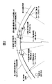
- FIG. 2 is a diagram showing an example of the shape of the curve.
- FIG. 3 is a diagram showing an example of changes in the radius of curvature and the turning state amount for the curve shown in FIG.
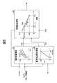
- FIG. 4 is a functional block diagram for explaining an outline of deceleration control and stabilization control executed by the travel control device shown in FIG.
- FIG. 5 is a functional block diagram for explaining calculation of the target vehicle speed by the target vehicle speed calculation means shown in FIG.
- FIG. 6 is a functional block diagram for explaining the calculation of the deceleration control target value by the deceleration control target value calculating means shown in FIG.
- FIG. 1 is a schematic configuration diagram of a vehicle equipped with a vehicle travel control apparatus according to a first embodiment of the present invention.
- FIG. 2 is a diagram showing an example of the shape of the curve.
- FIG. 3 is a diagram showing an example
- FIG. 7 is a functional block diagram for explaining calculation of the determination result by the execution feasibility determination unit shown in FIG. 4 and calculation of the stabilization control target value by the stabilization control target value calculation unit.
- FIG. 8 is a functional block diagram for explaining the calculation of the braking control target value by the target value adjusting means shown in FIG.
- FIG. 9 is a time chart showing an example when deceleration control is executed by the travel control device shown in FIG.
- FIG. 10 shows a vehicle travel control apparatus according to a modification of the first embodiment of the present invention.
- the final determination result by the execution determination unit shown in FIG. 4 is invalid based on a plurality of determination calculation results. It is the flowchart which showed an example of the process about the case where it changes into a valid state from a state.
- FIG. 8 is a functional block diagram for explaining calculation of the braking control target value by the target value adjusting means shown in FIG.
- FIG. 9 is a time chart showing an example when deceleration control is executed by the travel control device shown in
- FIG. 11 is a functional block diagram for explaining the determination calculation based on the azimuth angle shown in FIG.
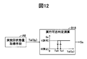
- FIG. 12 is a functional block diagram for explaining a determination calculation based on the actual turning state quantity shown in FIG.
- FIG. 13 is a functional block diagram for explaining the determination calculation based on the comparison between the turning direction and the curve direction shown in FIG.
- FIG. 14 is a functional block diagram for explaining a determination calculation based on a comparison between the calculated turning index and the actual turning index shown in FIG.
- FIG. 15 shows that the final determination result by the execution determination unit shown in FIG. 4 is valid based on a plurality of determination calculation results in the vehicle travel control apparatus according to the modification of the first embodiment of the present invention.
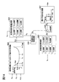
- FIG. 16 is a functional block diagram for explaining calculation when the target vehicle speed is adjusted based on the operation amount of the acceleration operation member by the driver.
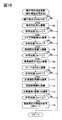
- FIG. 17 is a flowchart showing an example of processing related to the calculation of the azimuth shown in FIG.
- FIG. 18 is a diagram for explaining an example of the calculation of the azimuth angle in the case of a single curve.
- FIG. 19 is a diagram for explaining an example of the calculation of the azimuth angle in the case of the composite curve.
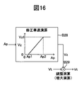
- FIG. 20 is a functional block diagram for explaining an outline of the curve information reliability evaluation executed by the vehicle travel control apparatus (curve information reliability evaluation apparatus) according to the second embodiment of the present invention.
- FIG. 16 is a functional block diagram for explaining calculation when the target vehicle speed is adjusted based on the operation amount of the acceleration operation member by the driver.
- FIG. 17 is a flowchart showing an example of processing related to the calculation of the azimuth shown in FIG.
- FIG. 18 is a diagram for explaining an example of the calculation of the azi
- FIG. 21 is a diagram illustrating a calculation example of the calculated turning index and the actual turning index.
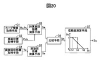
- FIG. 22 is a functional block diagram for explaining an overview of vehicle speed control executed by the vehicle travel control apparatus according to the second embodiment of the present invention.
- FIG. 23 is a functional block diagram for explaining the determination calculation by the first execution possibility determination unit shown in FIG.
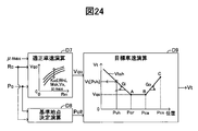
- FIG. 24 is a functional block diagram for explaining the calculation of the target vehicle speed by the target vehicle speed calculation means shown in FIG.
- FIG. 25 is a functional block diagram for explaining the reference point determination calculation shown in FIG.
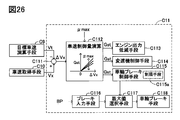
- FIG. 26 is a functional block diagram for explaining the vehicle speed control by the vehicle speed control means shown in FIG.
- FIG. 27 is a time chart for explaining that the change gradient of the braking torque is limited by the limiting means of the wheel brake control means shown in FIG.
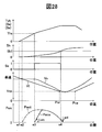
- FIG. 28 is a time chart showing an example when vehicle speed control is executed by the vehicle travel control apparatus according to the second embodiment of the present invention.
- FIG. 29 is a functional block diagram for explaining calculation when the target vehicle speed is adjusted based on the operation amount of the acceleration operation member by the driver.
- FIG. 30 is a functional block diagram for explaining the second and third execution feasibility judgment calculations performed in addition to the first execution feasibility judgment calculation.
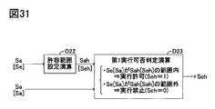
- FIG. 31 is a functional block diagram for explaining a case where an allowable range is considered when comparing the actual turning index and the calculated turning index.
- FIG. 32 is a graph for explaining an example of the allowable range shown in FIG.
- FIG. 1 shows a schematic configuration of a vehicle equipped with a travel control device (hereinafter sometimes referred to as “the present device”) according to a first embodiment of the present invention.
- This device includes an engine EG that is a power source of the vehicle, an automatic transmission TM, a brake actuator BRK, an electronic control unit ECU, and a navigation device NAV.
- the engine EG is, for example, an internal combustion engine. That is, the opening degree of the throttle valve TV is adjusted by the throttle actuator TH according to the operation of the accelerator pedal (acceleration operation member) AP by the driver.
- the automatic transmission TM is a multi-stage automatic transmission having a plurality of shift stages or a continuously variable automatic transmission having no shift stages.
- the brake actuator BRK has a known configuration including a plurality of solenoid valves, a hydraulic pump, a motor, and the like. When not being controlled, the brake actuator BRK supplies a brake pressure (brake hydraulic pressure) corresponding to the operation of the brake pedal (brake operation member) BP by the driver to the wheel cylinder WC ** of the wheel WH **, respectively. In some cases, the brake pressure in the wheel cylinder WC ** can be adjusted for each wheel independently of the operation of the brake pedal BP (and the operation of the accelerator pedal AP).
- the wheel cylinder WC ** comprehensively indicates a left front wheel wheel cylinder WCfl, a right front wheel wheel cylinder WCfr, a left rear wheel wheel cylinder WCrl, and a right rear wheel wheel cylinder WCrr.
- This device includes a wheel speed sensor WS ** that detects a wheel speed of the wheel WH **, a brake pressure sensor PW ** that detects a brake pressure in the wheel cylinder WC **, and a steering wheel SW (from a neutral position).
- a steering wheel angle sensor SA for detecting the rotation angle
- a front wheel steering angle sensor FS for detecting the steering angle of the front wheels
- a yaw rate sensor YR for detecting the yaw rate of the vehicle body
- an acceleration (deceleration) in the vehicle longitudinal direction A
- An acceleration operation amount sensor AS for detecting the operation amount a braking operation amount sensor BS for detecting an operation amount of the brake pedal BP, and a shift lever S
- a shift position sensor HS for detecting the position of the throttle valve
- a throttle valve opening sensor TS for detecting the opening of the throttle valve TV
- a self-aligning torque sensor ATf * for detecting the self-aligning torque of the steered wheel (front wheel)
- a steering torque sensor ST for detecting the steering torque of the steering wheel SW.
- the self-aligning torque sensor ATf * is fixed to the wheel rim of the steered wheel, for example, and detects the distortion of the wheel rim. Based on the information on the distortion and the position of the wheel rim where the distortion is detected, Detect self-aligning torque.
- the electronic control unit ECU is a microcomputer that electronically controls the powertrain system and the chassis system.
- the electronic control unit ECU is electrically connected to the various actuators described above, the various sensors described above, and the automatic transmission TM, or can communicate with a network.
- the electronic control unit ECU is composed of a plurality of control units (ECU1 to ECU4) connected to each other via a communication bus CB.
- the ECU 1 in the electronic control unit ECU is a wheel brake control unit and controls the brake actuator BRK based on signals from the wheel speed sensor WS **, the longitudinal acceleration sensor GX, the lateral acceleration sensor GY, the yaw rate sensor YR, and the like.
- braking pressure control wheel brake control
- ESC control vehicle stabilization control
- ABS control anti-skid control
- TCS control traction control
- the ECU 1 calculates a vehicle speed (vehicle speed) Vx based on a detection result (wheel speed Vw **) of the wheel speed sensor WS **.
- the ECU 2 in the electronic control unit ECU is an engine control unit that controls the output torque of the engine EG (engine control) by controlling the throttle actuator TH and the fuel injection actuator FI based on signals from the acceleration operation amount sensor AS and the like. Is supposed to run.
- the ECU 3 in the electronic control unit ECU is an automatic transmission control unit, and executes a reduction ratio control (transmission control) by controlling the automatic transmission TM based on a signal from the shift position sensor HS or the like. It has become.
- the ECU 4 in the electronic control unit ECU is an electric power steering control unit, and executes power steering control by controlling the electric power steering device EPS based on a signal from the steering torque sensor ST or the like.
- the navigation device NAV includes a navigation processing device PRC.
- the navigation processing device PRC includes a vehicle position detection means (global positioning system) GPS, a yaw rate gyro GYR, an input unit INP, a storage unit MAP, and a display unit (display). ) Electrically connected to the MTR.
- the navigation device NAV is electrically connected to the electronic control unit ECU or can communicate wirelessly.
- the vehicle position detection means GPS can detect the position (latitude, longitude, etc.) of the vehicle by one of the well-known methods using a positioning signal from an artificial satellite.
- the yaw rate gyro GYR can detect the angular velocity (yaw rate) of the vehicle body.
- the input unit INP is configured to input an operation related to the navigation function by the driver.
- the storage unit MAP stores various information such as map information and road information.
- the navigation processing device PRC comprehensively processes signals from the vehicle position detection means GPS, the yaw rate gyro GYR, the input unit INP, and the storage unit MAP, and displays the processing result (information related to the navigation function) on the display unit MTR. It is supposed to be.
- the (one) curve shown in FIG. 2 has a gradually decreasing curvature radius as the vehicle progresses in order from the curve start point Ci (curve entrance) to the curve end point Cd (curve exit).
- a constant curvature radius section Zit and an exit relaxation curve section Zcd (the curvature radius gradually increases as the vehicle advances).
- the relaxation curve is composed of a clothoid curve, for example.
- the relaxation curve section is provided so that the vehicle can smoothly pass the curve by gradually turning the steering wheel and then gradually turning back without requiring the driver to operate the steering wheel suddenly. It is for doing so.
- the radius of curvature is infinite at the curve start point Ci (that is, the end point of the straight road) and then gradually decreases to the start point of the constant curvature radius section Zit.
- Cs is Rm (the minimum radius of curvature in the curve).
- the radius of curvature is maintained at Rm until the end point Ce of the constant curvature radius section Zit, and then gradually increases and becomes infinite at the curve end point Cd (that is, the start point of the straight road).
- the turning state amount for example, lateral acceleration
- the turning state quantity starts to increase from “0 (straight travel)” at the curve start point Ci, and is approximately proportional in the approach relaxation curve section Zci.
- the constant curvature radius section Zit it becomes a constant value (maximum value).
- the turning state quantity decreases approximately proportionally in the exit relaxation curve section Zcd, and becomes “0 (straight running)” at the curve end point Cd.
- the “deceleration control” for decelerating the vehicle on the curve is required near the start point Cs of the constant curvature radius section Zit where the curvature radius becomes small on the curve.
- the steering characteristic of the vehicle does not require an intervention of “stabilization control” that stabilizes the turning state of the vehicle, but tends to be an understeer tendency in many cases.
- “stabilization control” that stabilizes the turning state of the vehicle, but tends to be an understeer tendency in many cases.
- the curve information Rc, Pc is stored in the map information database of the storage unit MAP.
- the position Pc for example, latitude / longitude information
- the curvature radius Rc of the curve at the position Pc can be directly stored.
- a format for example, an arithmetic expression and a coefficient
- a target vehicle speed Vt for stably passing through the target curve is calculated based on the curve information Rc, Pc and the vehicle position Pvh.
- the deceleration control target value calculation means A4 the target vehicle speed Vt and the vehicle speed Vx acquired by the vehicle speed acquisition means A5 are compared, and the deceleration control target value Gst (the target value of the wheel brake, the target value of the braking torque) Is calculated.
- the deceleration control target value Gst is determined based also on the determination result (control flag) So calculated by the execution permission determination means A9 described later.
- the calculated deceleration control target value Gst is output as it is to the target value adjusting means A11 described later.
- the actual turning state quantity acquisition means A6 acquires the actual yaw motion state quantity (actual turning state quantity Ta) of the vehicle.
- the actual turning state amount Ta is a yawing motion state amount actually generated with respect to the vehicle, and is, for example, the actual yaw rate Yr, the actual lateral acceleration Gy, the actual vehicle body slip angle ⁇ a, and the actual vehicle body slip angular velocity d ⁇ a. Further, a value obtained by combining two or more state quantities from among these can be used as the actual motion state quantity Ta.
- the target yaw motion state quantity (target turning state quantity Td) of the vehicle is acquired.
- the target turning state amount Td values of the same dimension (target yaw rate Yrd, target lateral acceleration Gyd, target vehicle body slip angle ⁇ d, target vehicle body slip angular velocity d ⁇ d) corresponding to the actual turning state amount Ta are calculated.
- the target turning state amount Td is calculated based on the vehicle speed Vx and the steering wheel angle ⁇ sw (or the front wheel steering angle ⁇ f).
- the vehicle steering characteristics (understeer, neutral steering, oversteer) are calculated based on the actual turning state quantity Ta and the target turning state quantity Td, and the calculation result (steer characteristic value) Sch is calculated.
- the steer characteristic value Sch is calculated to be a positive value.
- the steer characteristic can be calculated based only on the actual turning state amount Ta without using the target turning state amount Td.
- the steering characteristic value Sch can be calculated based on the actual vehicle body slip angular velocity d ⁇ a, the actual vehicle body slip angle ⁇ a, and the like.
- a judgment result (control flag) So of the execution of deceleration control is determined based on the steering characteristic value Sch.
- the final determination result by the feasibility determination unit A9 can be determined based on determination results (control flags Sy, Sd, Ss, Sm) other than the determination result (control flag) So based on the steer characteristic value Sch. . These will be described in detail later.
- the determination result by the execution feasibility determination unit A9 is determined based only on the determination result (control flag) So based on the steer characteristic value Sch.
- Sch ⁇ Sc1 predetermined value
- This determination is based on the assumption that “when the steering characteristic value is small, there is a low possibility that the vehicle is actually traveling in the curve (thus, the reliability of the curve information is low)”.
- “0” is output to the target value adjusting unit A11 as the deceleration control target value Gst.
- the predetermined value Sc1 is a threshold value for determining an understeer tendency of the vehicle. This determination is “at a stage where the steering characteristic value is large, there is a high possibility that the vehicle tends to understeer and the vehicle is actually traveling in the curve (thus, the reliability of the curve information is high).” Based on what is considered. As a result, the value calculated based on the comparison between the target vehicle speed Vt and the vehicle speed Vx is output as it is to the target value adjusting means A11 as the deceleration control target value Gst.
- the stabilization control target value Est (the target value of the wheel brake and the target value of the braking torque) is calculated based on the steering characteristic value Sch.
- Stabilization control is a known control that suppresses understeer and oversteer of a vehicle.
- the target value adjusting means A11 the deceleration control target value Gst and the stabilization control target value Est are adjusted, and the braking control target value Bt is calculated.
- the start condition of the stabilization control is Sch> Sc2 (predetermined value).
- the actual braking control amount (for example, braking pressure) Ba is controlled based on the braking control target value Bt.
- the wheel brake control means A12 for example, known means constituted by a pump, an electric motor, a solenoid valve, or the like can be used.
- This actual braking control amount (for example, braking pressure) Ba is output to the wheel brake means A13, and as a result, a braking force is generated on the wheel.
- wheel brake means A13 the well-known means comprised by a caliper, a rotor, a pad, etc. can be used, for example.
- the final determination result by the feasibility determination unit A9 is also based on determination results (control flags Sy, Sd, Ss, Sm) other than the determination result (control flag) So based on the steer characteristic value Sch. It can finally be determined.
- determination results control flags Sy, Sd, Ss, Sm
- control flag So based on the steer characteristic value Sch.
- it can finally be determined.
- a curvature radius Rm of a section where the curvature radius in the curve is constant (constant curvature radius section Zit) is determined, and the appropriate vehicle speed Vqo is determined based on the curvature radius Rm. Calculated. As the radius of curvature Rm, the minimum radius of curvature in the curve can also be used. The greater the curvature radius Rm, the greater the appropriate vehicle speed Vqo is calculated. Thus, the appropriate vehicle speed Vqo is determined so that the vehicle can pass the curve with substantially the same lateral acceleration regardless of the curvature radius Rm.
- the appropriate vehicle speed Vqo can be adjusted based on at least one of the uphill / downhill gradient Kud, the road width (width) Wrd, the forward view Msk, and the vehicle speed Vx.
- the uphill slope Kud is downhill
- the appropriate vehicle speed Vqo is adjusted to a lower value than when the road is flat, and when uphill, the appropriate vehicle speed Vqo is higher than that when the road is flat. Adjusted.
- the road width Wrd is narrow, the appropriate vehicle speed Vqo is adjusted to a smaller value than when the road width Wrd is wide.
- the road width Wrd is wide, the appropriate vehicle speed Vqo is adjusted to a larger value than when the road width Wrd is narrow. Is done.
- the appropriate vehicle speed Vqo is adjusted to a smaller value than when the forward view Msk is good.
- the appropriate vehicle speed Vqo is higher than when the forward view Msk is bad. Adjusted to a larger value.
- the vehicle speed Vx is high, the appropriate vehicle speed Vqo is adjusted to a smaller value than when the vehicle speed Vx is low, and when the vehicle speed Vx is low, the appropriate vehicle speed Vqo is adjusted to a larger value than when the vehicle speed Vx is high. Is done.
- the appropriate vehicle speed Vqo can also be adjusted based on the road surface friction coefficient ⁇ max.
- the appropriate vehicle speed Vqo is adjusted to a larger value than when the road surface friction coefficient ⁇ max is small, and when the road surface friction coefficient ⁇ max is small, the road surface friction coefficient ⁇ max is large. In comparison, the appropriate vehicle speed Vqo is adjusted to a smaller value.
- the calculation of the road surface friction coefficient ⁇ max is performed based on the wheel self-aligning torque Sat acquired by the self-aligning torque sensor ATf *. In the process in which the lateral force of the wheel increases, the self-aligning torque Sat also increases. In this process, the self-aligning torque Sat becomes the maximum value before reaching the state where the lateral force is saturated (that is, the turning limit state).
- the road surface friction coefficient ⁇ max can be estimated before the turning of the vehicle reaches the limit.
- the self-aligning torque Sat for example, one of known methods described in Japanese Patent Application Laid-Open Nos. 2008-24073, 2007-245901, and 2004-233331 is used. it can.
- the calculation of the road surface friction coefficient ⁇ max based on the self-aligning torque for example, one of known methods described in Japanese Patent Application Laid-Open No. 2007-245901 can be used.
- the reference point Pcr is determined.
- the reference point Pcr is a target point for reducing the vehicle speed to the appropriate vehicle speed Vqo by the deceleration control.
- the reference point Pcr can be set to an entrance point Cs (a point closest to the vehicle in the constant curvature radius section) where the curvature radius in the curve is constant. Further, the point Cs where the radius of curvature in the curve is minimum can be set as the reference point Pcr.
- the point Cs is determined based on the curve shape Rc and the curve position Pc.
- the point Pcr is set to the entrance point Cs of the constant curvature radius section or a point closer to the vehicle by the distance Lpr than the minimum curvature radius point (near the end of the relaxation curve corresponding to the entry part to the curve closer to the vehicle). be able to.
- the distance Lpr can be a constant value.
- the distance Lpr can be calculated according to the vehicle speed Vx.
- the distance Lpr is “0” (that is, the point Pcr coincides with Cs), and when Vx> V1 (predetermined value), the vehicle speed Vx increases from V1.
- the distance Lpr can be determined such that the distance Lpr increases from “0”.
- the vehicle speed Vx can be replaced with the appropriate vehicle speed Vqo, and the distance Lpr can be determined based on the appropriate vehicle speed Vqo.
- the point Pcr is set to a point on the curve close to the curve start point Ci by the distance Lpr from the point Cs.
- the point Pcr is set based on the distance Lpr, the curve shape Rc, and the point Cs (curve position Pc).
- the point Pcr is a target point for reducing the vehicle speed to the appropriate vehicle speed Vqo.
- the map information or the like may include an error.
- the error can be absorbed. That is, the vehicle speed control is started earlier in the curve, and the vehicle speed can be surely reduced to the appropriate vehicle speed Vqo at a point on the curve closer to the curve entrance Ci than the point Pcr.
- the target vehicle speed calculation block B3 the target vehicle speed Vt is calculated.
- a target vehicle speed calculation characteristic Vtch for calculating the target vehicle speed Vt (Vt [Pvh]) at the vehicle position Pvh is determined.
- the target vehicle speed calculation characteristic Vtch is a characteristic in which the vehicle speed decreases with a deceleration Gm (for example, a preset constant) from the curve entrance side to the reference point Pcr, and the vehicle speed becomes the appropriate vehicle speed Vqo at the reference point Pcr.
- the deceleration Gm can be set to a value in consideration of a general road surface friction coefficient on a wet road surface.
- the deceleration Gm can be adjusted based on the road surface friction coefficient ⁇ max.
- the deceleration Gm can be adjusted to a larger value as the road surface friction coefficient ⁇ max is larger.
- the target vehicle speed Vt at the vehicle position Pvh is calculated by inputting the vehicle position Pvh to the target vehicle speed calculation characteristic Vtch determined based on the reference point Pcr and the appropriate vehicle speed Vqo.
- the target vehicle speed Vt calculated in this way is output to the deceleration control target value calculation means A4 (see FIG. 4).
- the deceleration control target value calculation block B5 the deceleration control target value Gst is calculated based on the vehicle speed deviation ⁇ Vx. Specifically, the greater the deviation ⁇ Vx (> 0), the larger the deceleration control target value Gst is calculated. When the deviation ⁇ Vx is negative, Gst is calculated to “0”.
- deceleration control is executed when the vehicle speed Vx is higher than the target vehicle speed Vt (Vx> Vt), and deceleration control is not executed when the vehicle speed Vx is lower than the target vehicle speed Vt (Vx ⁇ Vt).
- the deceleration control target value Gst can be adjusted based on the road surface friction coefficient ⁇ max. Specifically, the deceleration control target value Gst is adjusted to a larger value as the road surface friction coefficient ⁇ max is larger. Thus, the deceleration control target value Gst calculated in the block B5 is output to the switching calculation block B6.
- the deceleration control target value Gst calculated in the block B5 is output as it is as the final deceleration control target value Gst.
- the final deceleration control target value Gst calculated and selected in this way is output to the target value adjusting means A11 (see FIG. 4).
- the final determination result by the execution determination unit A9 is also based on determination results (control flags Sy, Sd, Ss, Sm, which will be described later) other than the determination result (control flag) So based on the steer characteristic value Sch.
- the final deceleration control target value Gst is calculated and selected based on the final determination result by the execution determination unit A9.
- a target turning state calculation block B7 a yaw motion state amount (target turning state amount) Td of a target vehicle is calculated.
- Td a physical quantity of the same dimension corresponding to the actually generated yawing motion state quantity (actual turning state quantity) Ta is calculated.
- the target yaw rate Yrd is calculated as the target turning state quantity Td.
- Kh is a stability factor
- L is a wheel base of the vehicle
- SG is a steering gear ratio of the vehicle.
- the steer characteristic of the vehicle is calculated by comparing the target turning state quantity Td with the actual turning state quantity Ta of the same dimension corresponding to the target turning state quantity Td.
- the steer characteristic value Sch is approximately “0”, the vehicle is neutral steer.
- Sch ⁇ 0 the vehicle is oversteered, and the degree of oversteer increases as the absolute value of the steer characteristic value Sch increases.
- Sch>0 the vehicle is understeer, and the degree of understeer increases as the steer characteristic value Sch increases.
- the steer characteristic value Sch is calculated using the yaw rate
- ⁇ Yr Yrd ⁇ Yr
- the steer characteristic when the yaw rate deviation ⁇ Yr is approximately “0”, the vehicle is neutral steer.
- ⁇ Yr ⁇ 0 the vehicle is oversteered, and the greater the absolute value of the deviation ⁇ Yr, the greater the degree of oversteer.
- ⁇ Yr>0 the vehicle is understeer, and the degree of understeer increases as the deviation ⁇ Yr increases.
- the execution possibility determination calculation block B9 it is determined whether or not the deceleration control can be executed.
- the steer characteristic value Sch or the yaw rate deviation ⁇ Yr
- Sc1 preset
- the steer characteristic value Sch (or yaw rate deviation ⁇ Yr) is a predetermined value (set in advance).
- Sc0 ⁇ Sc1 there is a relationship of Sc0 ⁇ Sc1 between the predetermined values Sc0 and Sc1.
- the predetermined value Sc1 is set to a value smaller than a predetermined value Sc2 described later.
- the stabilization control target value Est is calculated based on the steer characteristic value Sch (or yaw rate deviation ⁇ Yr). Specifically, when the steer characteristic value Sch (or yaw rate deviation ⁇ Yr) is equal to or smaller than a predetermined value Sc2 (preset), the stabilization control target value Est is calculated to “0”. That is, Sch> Sc2 is a start condition for the stabilization control.
- the stabilization control target value Est is determined independently for each wheel so as to suppress excessive understeer and oversteer of the vehicle and maintain the steering characteristic appropriately.
- “fo” represents the front wheel outside the turn
- “ro” represents the rear wheel outside the turn
- “ri” represents the stabilization control target value Est for the rear wheel inside the turn.
- the braking control target value Bt is calculated by adding the stabilization control target value Est to the deceleration control target value Gst by “increase calculation”.
- the deceleration control target value Gst is stabilized by “selection calculation”. The control target value Est is adjusted.
- the wheel speed Vw ** detected by the wheel speed sensor WS ** (the subscript “**” indicates which wheel the symbol relates to, “fl” is the front left wheel, “fr”
- the braking torque applied to the wheel cannot be further increased.
- the deceleration control target value Gst is directly output to the wheel brake control means A12 as the braking control target value Bt for that wheel.
- the vehicle moment is appropriately generated.
- a value obtained by subtracting the stabilization control target value Est from the deceleration control target value Gst by the “decrease calculation” is output to the wheel brake control means A12 as the braking control target value Bt.
- the actual braking torque Ba (braking pressure) applied to the wheel brake means A13 is controlled based on the braking control target value Bt.
- the braking torque time gradient limiting means limits the change gradient with respect to time of the braking torque. Specifically, the increase gradient with respect to the time of Ba is limited to the predetermined value Lwc, and the decrease gradient with respect to the time of Ba is limited to the predetermined value Lwd.
- the deceleration control can be executed using the deceleration that can be adjusted by using the downshift of the automatic transmission TM.
- the deceleration control is not started, and the actual braking torque (braking pressure) Ba is also maintained at “0”.
- the vehicle enters the curve (passes the curve start point Ci), and the steering characteristic value Sch starts increasing from “0”.
- the deceleration control target value Gst is switched to a value (> 0) calculated based on ⁇ Vx. That is, the deceleration control is started, and the actual braking torque Ba (> 0) is started to be applied. As a result, the vehicle starts to decelerate.
- the time gradient limit Lwc is provided for the increase in the braking torque. For this reason, even if deceleration control is suddenly started, the actual braking torque (braking pressure) Ba does not increase suddenly, and therefore the vehicle is not suddenly decelerated.
- the steering characteristic value Sch becomes smaller than the predetermined value Sc0 ( ⁇ predetermined value Sc1).
- the time gradient limit Lwd is provided for the reduction of the braking torque. For this reason, even if the deceleration control is terminated suddenly, the actual braking torque (braking pressure) Ba does not decrease rapidly, and therefore the vehicle deceleration does not decrease rapidly. In the example shown in FIG.
- the deceleration control may be started when the condition (deceleration control start condition) is satisfied. As shown in FIG. 9, in this device, the deceleration control is started when the curvature radius Rc of the curve after entering the curve gradually decreases and the steering characteristic value Sch reaches a value indicating an understeer tendency.
- the steer characteristic value Sch does not reach a value indicating an understeer tendency, and thus deceleration control is not executed. That is, it is possible to prevent the deceleration control from being started and executed unnecessarily based on the low-reliability curve information.
- the deviation (steer characteristic value Sch) between the target turning state amount Td and the actual turning state amount Ta is calculated after the vehicle enters the curve.
- the deceleration control can be executed based only on the curve information with high reliability.
- the processing is started when the acquired curve information Rc, Pc and the actual curve shape are different due to the modification of the curve in the vicinity of the curve entrance (particularly, the modification from the curve to the straight road). It is possible to inhibit the deceleration control that should not be started.
- the present invention is not limited to the first embodiment, and various modifications can be employed within the scope of the present invention.
- the determination result by the execution feasibility determination unit A9 is based only on the determination result (control flag) So based on the steer characteristic value Sch, but the final determination result by the execution propriety determination unit A9
- the (control flag Sfin) may be determined based on another determination result (control flags Sy, Sd, Ss, Sm) instead of or in addition to the determination result (control flag) So based on Sch.
- control flag Sfin when the control flag Sfin is “1”, it indicates that the final determination result by the execution determination unit A9 is in a permitted state (a state in which the execution of the deceleration control is permitted), and when the control flag Sfin is “0” It represents that the final determination result by the permission determination means A9 is a prohibited state (a state in which execution of deceleration control is prohibited).
- the “prohibited state” corresponds to the “invalid state”, and the “permitted state” corresponds to the “valid state”.
- the routine corresponding to this flowchart is repeatedly executed every elapse of a predetermined time (for example, 6 msec).
- a predetermined time for example, 6 msec.
- the azimuth angle Ya is an angle formed by the traveling direction of the vehicle at the vehicle position (the direction in which the vehicle is facing) with respect to the direction of the straight line portion before the curve entrance.
- the “direction of the straight line portion before the curve entrance” is determined based on, for example, the straight line portion based on the transition of the actual turning state amount within a predetermined distance (for example, 20 m) in which the vehicle has traveled. It can be determined based on the traveling direction of the vehicle on the straight line portion.
- the predetermined distance is an error in the position of the curve entrance Ci determined based on the map information stored in the storage unit MAP, and an error in the vehicle position Pvh acquired by the global positioning system GPS or the like. Etc. are determined to values that can be absorbed.
- the azimuth angle Ya is calculated based on the actual turning state amount Ta (for example, the actual yaw rate Yr).
- the actual yaw rate Yr is acquired as the actual turning state amount Ta
- the azimuth (yaw angle) Ya is calculated by integrating (integrating) Yr from the curve entrance Ci.
- the azimuth angle Ya2 at the curve exit Cd (or the end point Ce of the constant curvature radius section) is calculated based on the curve information Rc and Pc.
- the azimuth angle Ya2 is an angle formed by the tangential direction of the curve at the curve exit Cd (or the point Ce) with respect to the direction of the straight line portion before the curve entrance.
- a predetermined value Ya1 is calculated based on the vehicle speed Vx. Specifically, the greater the vehicle speed Vx, the smaller the predetermined value Ya1 is calculated.
- the determination calculation is “at a stage where the azimuth angle Ya is small (less than Ya1), the possibility that the vehicle is actually traveling in the curve is low (thus, the reliability of the curve information is low), and Ya is large ( At the stage of Ya1 or higher), it is highly likely that the vehicle is actually traveling in the curve (thus, the reliability of the curve information is high).
- the azimuth angle Ya is an integrated value of the actual yaw rate Yr from the curve entrance Ci. Therefore, even when the position of the vehicle fluctuates in the width direction of the road after entering the curve (when the vehicle fluctuates), the azimuth angle Ya can represent the traveling direction of the vehicle when viewed macroscopically. .
- the determination result (control flag) Sy accurately determines whether the reliability of the curve information is high, that is, whether or not the deceleration control can be executed. can do.
- the azimuth angle Ya is equal to or greater than the predetermined value Ya1” corresponds to “the turning with respect to the curve is detected”.
- “turning with respect to a curve” may be detected based not only on the calculated azimuth angle but also on a detected value (actual measurement value) such as an actual yaw rate or steering wheel angle, or may be an imaging device such as an in-vehicle camera. Alternatively, it may be detected using a sensor such as a millimeter wave laser radar.
- the three-dimensional object moves at a constant speed in the screen according to the vehicle speed, and the position of the three-dimensional object in the screen changes. At this time, the three-dimensional object moves in a fixed manner around the vanishing point in the screen. However, when the left / right turn is performed, the three-dimensional object moves uniformly left and right from the screen edge in the screen. Accordingly, the “turning with respect to the curve” may be detected based on the detection that the three-dimensional object in the screen moves uniformly left and right from the screen edge.
- a turn is made based on the “positional relationship between the detected object (stationary object) and the own vehicle” and the “vehicle speed of the own vehicle”. It becomes possible to judge. Specifically, when a stationary object is detected during turning, the stationary object moves in the horizontal direction within the screen, and the distance between the stationary object and the host vehicle becomes longer. Therefore, when a stationary object is detected and the detection result indicates that the stationary object moves laterally in the screen and the distance between the stationary object and the own vehicle becomes longer after that, "Turning with respect to a curve" may be detected. Referring to FIG.
- step 103 if “No” is determined in step 103 (Ya ⁇ Ya1), this routine is immediately terminated.
- the calculation of the determination result (control flag) So based on Sch (the processing of steps 104 and 105) is the same as the calculation of blocks B7, B8, and B9 shown in FIG. If “No” is determined in step 105 (Sch ⁇ Sc1), this routine is immediately terminated.
- the calculation of the determination result (control flag) Ss based on Ta (processing in steps 106 and 107) will be described in detail with reference to FIG.
- the actual turning state amount acquisition means A6 acquires the actual turning state amount Ta (for example, the actual lateral acceleration Gy).
- the determination result (control) is performed at a stage where the actual turning state amount Ta (for example, Gy) is less than the predetermined value Ta1.
- the determination calculation is as follows: “At the stage where the actual turning state amount Ta (for example, Gy) is small (less than Ta1), the possibility that the vehicle is actually traveling in the curve is low (therefore, the reliability of the curve information is low). Low), when Ta (for example, Gy) is large (Ta1 or higher), the vehicle is likely to actually travel in the curve (thus, the reliability of the curve information is high). based on. On the other hand, in the process in which the actual turning state amount Ta (for example, Gy) is decreasing, the determination result (control flag) Ss is in the permitted state when the actual turning state amount Ta (for example, Gy) is greater than the predetermined value Ta0.
- the calculation of the determination result (control flag) Sd based on Dvh and Dcv processing of steps 108, 109, and 110 will be described in detail with reference to FIG.
- the turning direction Dvh of the vehicle is identified based on the actual turning state amount Ta.
- the vehicle when the absolute value of the actual turning state amount Ta is less than the predetermined value Ts, the vehicle is identified as “straight ahead”.
- the absolute value of the actual turning state amount Ta is equal to or greater than the predetermined value Ts, the vehicle is identified as turning, and “left turning” or “right turning” is identified by the sign of the actual turning state amount Ta at that time.
- any one of “straight ahead”, “left turn”, and “right turn” is calculated as the turning direction Dvh.
- the curve direction Dcv with respect to the traveling direction of the vehicle is identified based on the curve information Rc, Pc and the vehicle position Pvh.
- the curve direction Dcv is identified as “straight line”.
- “left curve” or “right curve” is identified by the direction of the curve curvature radius Rvh. That is, any one of “straight line”, “left curve”, and “right curve” is calculated as the curve direction Dcv.
- the determination calculation is as follows: “If the turning direction Dvh and the curve direction Dcv match, the reliability of the curve information is high, and if the turning direction Dvh and the curve direction Dcv do not match, the reliability of the curve information is low”. Based on thoughts. Referring to FIG. 10 again, if “No” is determined in step 110 (Dvh and Dcv do not match), this routine is immediately terminated.
- step 111 the calculated turning index Se is calculated, and in the subsequent step 112, the actual turning index Sa is calculated, and the following step In step 113, a comparison result Sh between Se and Sa is calculated.
- the calculation of the determination result (control flag) Sm based on Sh (the processing of steps 111, 112, 113, and 114) will be described in detail with reference to FIG.
- the curve curvature radius calculation block B22 calculates the curvature radius Rvh of the curve at the vehicle position Pvh.
- the relationship (curvature radius calculation characteristic) Rch between the position Pc in the curve and the curvature radius Rc is calculated based on the curve information Rc, Pc.
- the radius-of-curvature calculation characteristic Rch can be estimated based on a curve obtained by connecting geometrically and smoothly the positions of a plurality of points (node points) on a road stored in advance (for example, Japanese Patent No. 3378490). See).
- the radius-of-curvature calculation characteristic Rch can be stored in a map information database using a function representing a relaxation curve (for example, a clothoid curve), a parameter, and the like.
- the curve curvature radius Rvh at the vehicle position Pvh is calculated. That is, by inputting the vehicle position Pvh to the curvature radius calculation characteristic Rch defined by the relationship between the position and the curvature radius, the curve curvature radius Rvh at the vehicle position Pvh is calculated.
- the calculated turning state quantity calculation block B23 the calculated turning state quantity Te is calculated based on the calculated curvature radius Rvh. The following state quantities can be calculated as the calculated turning state quantity Te.
- the calculated turning index Se is calculated based on the calculated turning state quantity Te.
- the curve curvature radius Rvh itself calculated as described above can be used as the calculated turning index Se.
- the calculated turning index Se can be calculated by combining two or more of the calculated turning indices Se described above.
- the actual turning index calculation block B25 the actual turning index Sa is calculated based on the actual turning state amount Ta.
- the same (dimensional) physical quantity (state quantity) is calculated as the actual turning index Sa and the calculated turning index Se.
- the curve curvature radius Rta is calculated based on the actual turning state amount Ta as the actual turning index Sa corresponding to the calculated turning index Se.
- Rta can be acquired by any of the following operations.
- Rta Vx 2 / Gya
- Rta Vx / Yra
- Rta [L ⁇ (1 + Kh ⁇ Vx 2 )] / ⁇ fa
- Rta [SG ⁇ L ⁇ (1 + Kh ⁇ Vx 2 )] / ⁇ swa
- Kh is a stability factor
- L is a wheel base of the vehicle
- SG is a steering gear ratio of the vehicle.
- the comparison calculation block B26 the calculated turning index Se and the actual turning index Sa are compared.
- the comparison result Sh the absolute value of the deviation between the actual turning index Sa and the calculated turning index Se (turning index deviation) can be used.
- a determination result (control flag) Sm is calculated based on the turning index deviation Sh.
- the determination calculation is as follows: “If the calculated turning index Se calculated based on the map information and the actually detected turning index Sa are substantially coincident (Sh ⁇ Sh1), the reliability of the curve information is high, If the difference between Se and Sa is large (Sh> Sh1), the reliability of the curve information is low ”.
- Such determination of whether or not to execute control is continued even after deceleration control is started.
- the deceleration control being executed can be stopped.
- the azimuth angle Ya, the steer characteristic value Sch, the actual turning state amount Ta, the turning direction Dvh, the curve direction Dcv, and the actual turning index Sa in the processing shown in FIG. 10 are determined state amounts (determining whether or not deceleration control can be executed).
- the predetermined values Ya1, Sc1, Ta1, Ts, Rvs, and Ths are the turning state of the vehicle when traveling on the entrance side from the central point of the approach relaxation curve section (entrance clothoid curve section) of the target curve, Or it can be set as the value equivalent to the state of a curve. Therefore, it is possible to complete the control execution determination in the first half portion of the target curve in the approach relaxation curve section.
- the vehicle speed control which decelerates a vehicle in the second half part in the approach relaxation curve area of the same curve can be started.
- the determination result based on Ya control flag Sy
- the determination result based on Sch control flag
- determination result based on Ta control flag Ss
- determination result based on Sh control flag Sm
- the “prohibited state” corresponds to the “invalid state”
- the “permitted state” corresponds to the “valid state”.
- a plurality of determination calculation results (Sy, So, Ss) corresponding to a plurality of determination state quantities (Ya, Sch, Ta, Dvh, Dcv, and Sa) calculated based on the actual turning state quantity Ta. , Sd, and Sm) by calculating the final determination result (control flag Sfin) by the execution determination unit A9 (see FIG. 4), it is possible to improve the determination accuracy of the deceleration control execution determination. it can.
- the execution start permission determination see FIG. 10
- the control prohibition determination during execution see FIG.
- the determination operation based on Ya the determination operation based on Sch, the determination operation based on Ta, and based on Dvh and Dcv
- the determination calculation and the determination calculation based on Sh are provided, and the calculation necessary for the determination calculation (for example, step 102 required for the determination calculation based on Ya) is included. At least one or more can be omitted. That is, at least one of the five determination calculations is provided, and an execution start permission determination and a control prohibition determination during execution are performed.
- any one of a determination calculation based on Ya, a determination calculation based on Sch, a determination calculation based on Ta, a determination calculation based on Dvh, Dcv, and a determination calculation based on Sh is “first execution”.
- any one of the determination operations different from the first execution determination unit corresponds to a “second execution determination unit different from the first execution determination unit”.
- the target vehicle speed Vt calculated in the target vehicle speed calculation means A3 shown in FIG. 4 (specifically, the block B3 shown in FIG. 5) is used as the acceleration operation of the driver's acceleration operation member AP. It can be adjusted in the increasing direction based on the amount Ap.
- the corrected vehicle speed Vz is calculated in the corrected vehicle speed calculation block B28 based on the acceleration operation amount Ap.
- the corrected vehicle speed Vz is calculated to be “0” when Ap is equal to or less than Ap1 (predetermined value), and to increase from “0” as Ap increases from Ap1. Furthermore, an upper limit Vz1 can be provided for the corrected vehicle speed Vz so that Ap is equal to or higher than Ap2 (predetermined value) and Vz is constant to Vz1 (predetermined value).
- the adjusted target vehicle speed Vt is output to the deceleration control target value calculation means A4 (see FIG. 4).
- step 301 an integration start point Psk that is a point at which the integration calculation of the azimuth angle Ya is started is set.
- the point Psk can be set as a point closer to the vehicle (near side) by a predetermined distance (predetermined value) Lsk from the curve entrance Ci.
- the point Psk is determined based on the position of the curve entrance Ci stored in the storage unit MAP (or calculated based on the information stored in the storage unit MAP). Further, the position of the point Psk can be stored in advance in the storage unit MAP.
- an integration end point Psl that is a point at which the integration calculation is ended is set.
- the point Psl can be set as a point closer to the vehicle (near side) by a predetermined distance (predetermined value) Lsl from Cd.
- the point Psl is determined based on the position of the curve exit Cd stored in the storage unit MAP (or calculated based on the information stored in the storage unit MAP). Further, the position of the point Psl can be stored in advance in the storage unit MAP.
- first curve the integration end point Psl1 corresponding to the curve closest to the vehicle
- second curve the curve closest to the vehicle
- second curve coincides with the integration start point Psk2 corresponding to (1)), or is present in front of the point Psk2 (side closer to the vehicle).
- step 303 it is determined whether or not the integration calculation of the azimuth angle Ya is being executed. Integration of the azimuth angle Ya has been started, and if an affirmative determination (YES) is made in step 303, the arithmetic processing proceeds to step 305. If the integration of the azimuth angle Ya has not yet been started and a negative determination (NO) is made in step 303, the arithmetic processing proceeds to step 304. In step 304, it is determined whether or not the vehicle has passed the point Psk. If the vehicle has not yet reached the point Psk, a negative determination is made in step 304, and the azimuth is not calculated.
- step 304 determines whether or not the vehicle has passed the point Psl. If the vehicle has reached or passed the point Psl, an affirmative determination is made in step 305, and the calculation process proceeds to step 309. In Step 309, the azimuth calculation (integration) is terminated, and the azimuth Ya is reset to “0”. On the other hand, if the vehicle has not yet reached the point Psl, a negative determination is made in step 305 and the calculation process proceeds to step 306.
- step 306 it is determined whether or not the actual turning state amount Ta (for example, the steering wheel angle ⁇ sw, the front wheel steering angle ⁇ f) is within a predetermined range (the absolute value
- the actual turning state amount Ta for example, the steering wheel angle ⁇ sw, the front wheel steering angle ⁇ f
- the azimuth angle Ya (integrated value) is set to “0”.
- step 308 an integral calculation (integration) process for calculating the azimuth angle Ya is performed.
- the azimuth Ya is reset when the actual turning state amount Ta is within a predetermined range as long as the vehicle has passed the point Psk and before the point Psl.
- the azimuth angle Ya may always be reset when the actual turning state amount Ta is within the predetermined range.
- An error is included in the position of the curve entrance Ci determined based on the information stored in the storage unit MAP.
- the vehicle position Pvh acquired by the global positioning system GPS or the like includes an error.
- the integration calculation of the azimuth angle Ya is started from a point before the curve entrance Ci by a predetermined value (predetermined distance) Lsk, so that these errors can be compensated.
- Lsk a value that can absorb these errors is used.
- Lsk can be set based on at least one of the accuracy of the storage unit MAP and the performance of GPS.
- the front side of the curve entrance Ci is a straight section, and the integration of the azimuth angle Ya is started before the curve entrance Ci (the side closer to the vehicle). For this reason, the azimuth angle Ya is calculated to be approximately zero in the section up to the curve entrance Ci.
- the actual turning state amount Ta (for example, the steering angle Str (a general term for ⁇ sw and ⁇ f)) is within a predetermined range (that is, Ta is within a range corresponding to straight running).
- the value of the azimuth angle Ya is reset and returned to “0”.
- the azimuth angle Ya is also generated when a lane change or the like is performed during straight running.
- Ta returns to “0” after the lane change is completed, the azimuth angle Ya is reset. Thereby, the approach into the curve of the vehicle can be reliably determined.
- FIGS. 18 and 19 the operation and effect will be described by the above-described calculation of the azimuth angle.
- a curve ahead of the vehicle is recognized at the vehicle position (1).
- the start point Psk of the azimuth calculation is set in front of the curve entrance Ci by a predetermined value Lsk (side closer to the vehicle).
- the azimuth calculation end point Psl is set to the near side by a predetermined value Lsl from the curve exit Cd (or farther from the end point Ce of the constant curvature radius section by a predetermined distance Lsm (side away from the vehicle)).
- the azimuth angle Ya is an angle between the direction of the straight section Zst and the direction of the vehicle. Since the section from the point Psk to the curve entrance Ci is a straight line, the azimuth angle Ya is calculated to be approximately “0”. After the vehicle passes through the curve entrance Ci, the Ya calculation is started, but when the actual turning state amount Ta is within a predetermined range (when the absolute value of Ta is within the predetermined value Tsk), FIG. At every calculation cycle of the routine shown, the azimuth angle Ya is reset and returned to “0”. When the vehicle enters the approach relaxation curve section Zci, the azimuth angle Ya gradually increases from “0 (corresponding to traveling on a straight road)”.
- the determination result Sy is switched from the prohibited state (invalid state of deceleration control) to the permitted state (effective state of deceleration control). Furthermore, the azimuth calculation ends when the vehicle travels and reaches the integration end point Psl.
- the determination result Sy is switched from the permitted state (valid state) to the prohibited state (invalid state) when the azimuth angle Ya becomes equal to or greater than the predetermined value Ya2 or when the azimuth angle calculation is completed. In this way, the azimuth angle integration calculation is started before the curve entrance Ci (by the distance Lsk). For this reason, errors in the storage unit MAP and GPS can be compensated.
- the azimuth angle Ya is reset based on the actual turning state amount Ta. For this reason, even if a lane change or a wobble in the lane occurs, it can be reliably identified that the vehicle has entered the curve.
- a so-called S curve a case where a plurality of curves are continuous (a case where two curves are connected without sandwiching a straight section) will be described with reference to FIG. This is called a so-called S curve.
- the exit relaxation curve section Zcj of the first curve (the curve closest to the vehicle) and the approach relaxation curve section Zci of the second curve (the curve next to the first curve ahead of the vehicle) are at the point Ci. Connected.
- the exit of the curve including the constant curvature radius Rn and the entrance of the curve including the constant curvature radius Rm coincide.
- the direction of the vehicle at Ci where Zcj and Zci are connected corresponds to the direction of the straight section.
- a curve (second curve) including a constant radius of curvature Rm is the target of deceleration control, and the vehicle is traveling at position (3).
- the calculation of Ya is once ended.
- the Ya calculation is started.
- the point Psk2 is set closer to the vehicle by a predetermined value Lsk than the curve entrance Ci.
- the point Psk2 is set within the exit relaxation curve section Zcj of the first curve. For this reason, although the azimuth angle Ya is integrated, the actual turning state amount Ta is within a predetermined range (Ta is less than Tsk), and therefore Ya is reset to zero every calculation cycle.
- the azimuth angle Ya is gradually increased from zero.
- the determination result Sy is switched from the prohibited state (invalid state) to the permitted state (valid state).
- the determination result Sy is switched from the permitted state to the prohibited state.
- the azimuth angle Ya is reset based on the actual turning state amount Ta. For this reason, even when the point Psk is set within the relaxation curve section (corresponding to the first curve), the approach to the curve (second curve) can be reliably identified.
- the calculation of the azimuth angle Ya is performed based on the actual yaw rate Yr. Instead of the actual yaw rate Yr, a calculated yaw rate Yre calculated from another state quantity (for example, the steering angle Str) can be used.
- the steering wheel angle ⁇ sw detected by the steering wheel angle sensor SA and the steering angle ⁇ f of the steered wheel (front wheel) detected by the front wheel steering angle sensor FS are collectively referred to as a steering angle Str.
- the calculated yaw rate Yre1 (first calculated yaw rate) can be calculated based on the speed difference ⁇ Vw between the left and right wheels.
- the calculated yaw rate Yre2 (second calculated yaw rate) can be calculated based on the steering angle.
- the calculated yaw rate Yre3 third calculated yaw rate
- any one of the speed difference ⁇ Vw between the left and right wheels, the steering angle Str, and the actual lateral acceleration Gy can be integrated to calculate the azimuth angle Ya.
- the azimuth angle Ya can be calculated by combining two or more of the actual yaw rate Yr and the calculated yaw rates Yre1, Yre2, and Yre3.
- the present device a travel control device and a curve information reliability evaluation device (hereinafter sometimes referred to as “the present device”) according to a second embodiment of the present invention will be described. Since the mechanical configuration of the second embodiment is exactly the same as that of the first embodiment, detailed description thereof is omitted here.
- the curve information acquisition means C1 acquires information Rc, Pc (curve radius Rc at the position and the position Pc) of the curve ahead of the vehicle.
- the curve information Rc, Pc is stored in the map information database of the storage unit MAP.
- a position Pc for example, latitude / longitude information
- a curvature radius Rc of the curve at the position Pc are stored as a set of the position Pc and the curvature radius Rc.
- the position Pc and the curvature radius Rc can be stored in the database according to a format (for example, an arithmetic expression and a coefficient) in which the position Pc and the curvature radius Rc can be calculated.
- the vehicle position acquisition unit C2 acquires the current position Pvh of the vehicle.
- the vehicle position Pvh is detected using the global positioning system GPS.
- the calculated turn index calculation means C3 calculates the calculated turn index Se at the vehicle position Pvh of the running curve.
- This calculated turning index Se is an index representing the degree of turning of the vehicle calculated based on the vehicle position Pvh and the curve information Rc, Pc.
- FIG. 21 shows an example of the calculated turning index Se. As shown in FIG.
- the curvature radius Rvh itself at the current vehicle position Pvh can be used as the calculated turning index Se.
- the curvature radius Rvh can be calculated by inputting the vehicle position Pvh to the relationship Rch (described later) between the position in the target curve and the curve curvature radius. Further, as shown in FIG. 21, based on the curvature radius Rvh at the current vehicle position Pvh, the calculated lateral acceleration Gye, the calculated yaw rate Yre, the calculated pre-wheel steering angle ⁇ fe, the calculated steering wheel angle ⁇ swe, the calculated wheel speed left-right difference ⁇ Vwe, And at least one of the calculated azimuth angles Yae can be calculated as the calculated turning index Se.
- the actual turning state amount acquisition means C4 acquires the actual turning state amount Ta (value representing the actual turning state) of the vehicle.
- the actual turning state amount Ta at least one of actual lateral acceleration Gya, actual yaw rate Yra, actual front wheel steering angle ⁇ fa, actual steering wheel angle ⁇ swa, actual wheel speed left-right difference ⁇ Vwa, and actual azimuth angle Yaa is acquired ( Detection or calculation).
- the actual turning index calculation means C5 calculates the actual turning index Sa based on the actual turning state quantity Ta.
- the actual turning index Sa is an index representing the actual degree of turning of the vehicle. As shown in FIG.
- the actual turning index Sa is the actual turning state amount Ta, the actual lateral acceleration Gya, the actual yaw rate Yra, the actual front wheel steering angle ⁇ fa, the actual steering wheel angle ⁇ swa, the actual wheel speed left-right difference ⁇ Vwa, and At least one of the actual azimuth angles Yaa can be used. Furthermore, as shown in FIG. 21, the curvature radius Rta of the curve calculated using these actual turning state quantities Ta can be used as the actual turning index Sa. Alternatively, a value calculated by combining two or more of these (two or more types) can be used as the actual turning index Sa.
- the comparison means C6 compares the calculated turning index Se with the actual turning index Sa. Specifically, the deviation Sh of the turning index (the absolute value
- the reliability calculation means C7 calculates a reliability Sq that is a result of evaluating the reliability of the acquired curve information Rc, Pc.
- the reliability Sq is calculated based on the calculated turning index Se and the actual turning index Sa that change from moment to moment.
- the reliability Sq can be calculated based on the average value of the calculated turning index Se and the actual turning index Sa in a predetermined range (predetermined time or predetermined distance).
- the reliability Sq can be calculated based on the transition of the turn index deviation Sh until the calculated turn index Se or the time when the actual turn index Sa reaches the predetermined value Ths after the vehicle passes the curve start point Ci. . (Outline of vehicle speed control in the curve by this device)
- the vehicle speed control curve vehicle speed control executed by the present apparatus for decelerating the vehicle within the curve will be described with reference to FIG.
- the same or equivalent means as those shown in the previous figures are denoted by the same reference numerals as those shown in the previous figures, and their explanations are substituted.
- the curve information acquisition means C1 the vehicle position acquisition means C2, the calculated turning index calculation means C3, the actual turning state quantity acquisition means C4, the actual turning index calculation means C5, and the comparison means C6 shown in FIG.
- the first execution possibility determination means C8 it is determined whether or not to perform the curve vehicle speed control based on the above-described turning index deviation Sh.
- a value (vehicle turning value) Tvh representing the turning state of the vehicle calculated based on at least one of the curve information Rc, Pc and the actual turning state amount Ta is provided to the first execution determination unit C8. Control is executed based on the transition of the turning index deviation Sh from the time when the vehicle enters the curve (the time when the vehicle passes the curve start point Ci) to the time when the vehicle turning value Tvh reaches a predetermined value Ths set in advance. Is determined. Further, at least one of the actual turning index Sa and the calculated turning index Se is provided, and from the time when the vehicle enters the curve until the time when the actual turning index Sa or the calculated turning index Se reaches a predetermined value Ths set in advance.
- the predetermined value Ths can be set to a value corresponding to the turning state of the vehicle when traveling on the entrance side from the central point of the entry relaxation curve section (entrance clothoid curve section) of the target curve.
- the predetermined value Ths can also be a value corresponding to a preset vehicle turning state (for example, lateral acceleration is 0.3 to 0.4 G).
- the vehicle turning value Tvh or the actual turning index Sa, calculated based on at least one of the curve information Rc, Pc and the actual turning state amount Ta from the time when the vehicle enters the curve.
- the state in which the turning index deviation Sh is equal to or less than the predetermined value Sh1 is continued over the predetermined range Hn1 (the predetermined distance Ls1 or the predetermined time Ts1).
- the vehicle turning value Tvh (or the actual turning index Sa or the calculated turning index Se) calculated based on at least one of the curve information Rc, Pc and the actual turning state amount Ta is the predetermined value Ths.
- the determination of whether or not the control can be executed can be completed in the first half portion of the approach relaxation curve section of the target curve.
- the vehicle speed control for decelerating the vehicle in the second half of the approach relaxation curve section of the same curve can be started.
- the vehicle speed control means C11 described later
- the first execution possibility determination means C8 continues to calculate the deviation Sh.
- the target vehicle speed calculation means C9 calculates a target vehicle speed Vt for stably passing through the target curve based on the curve information Rc, Pc and the vehicle position Pvh. Details of this calculation will be described later.
- the actual vehicle speed Vx of the vehicle is acquired.
- control start / end conditions and “control permission / prohibition conditions” are considered. Whether or not the curve vehicle speed control should be performed is determined by the “control start / end condition”. Specifically, the acquired vehicle speed Vx and the target vehicle speed Vt are compared, and the control start condition is satisfied when the actual vehicle speed Vx exceeds the target vehicle speed Vt. Further, the control end condition is established when the actual vehicle speed Vx falls below the target vehicle speed Vt. On the other hand, whether or not to execute the vehicle speed control is determined based on the “control permission / prohibition condition”.
- permission or prohibition of vehicle speed control execution is determined based on the determination result (control flag So) of the first execution determination unit C8. Furthermore, permission or prohibition of vehicle speed control execution is determined by a combination of the control flag So and control flags Sr and Ss described later.
- the vehicle speed control means C11 actually starts the curve vehicle speed control.
- the curve vehicle speed control is not actually started. .
- the road surface friction coefficient ⁇ max is calculated by the road surface friction coefficient calculation unit C13 based on the wheel self-aligning torque Sat acquired by the self-aligning torque acquisition unit C12.
- the self-aligning torque Sat also increases.
- the self-aligning torque Sat becomes the maximum value before reaching the state where the lateral force is saturated (that is, the turning limit state). For this reason, the road surface friction coefficient ⁇ max can be estimated before the turning of the vehicle reaches the limit.
- the estimated road friction coefficient ⁇ max is used for calculation of the target vehicle speed Vt and calculation in the vehicle speed control means C11.
- the self-aligning torque Sat for example, one of known methods described in Japanese Patent Application Laid-Open Nos. 2008-24073, 2007-245901, and 2004-233331 is used. it can.
- the calculation of the road surface friction coefficient ⁇ max based on the self-aligning torque for example, one of known methods described in Japanese Patent Application Laid-Open No. 2007-245901 can be used.
- the control execution is prohibited in a certain curve by the first execution possibility determination means C8, the fact that the control execution is prohibited can be stored in association with the curve information.
- the vehicle position Pvh is acquired by the global positioning system. Specifically, first, the relationship (curvature radius calculation characteristic) Rch between the position Pc in the curve and the curvature radius Rc is calculated based on the curve information Rc, Pc.
- the radius-of-curvature calculation characteristic Rch can be estimated based on a curve obtained by connecting geometrically and smoothly the positions of a plurality of points (node points) on a road stored in advance (for example, Japanese Patent No. 3378490). See).
- the radius-of-curvature calculation characteristic Rch can be stored in a map information database using a function representing a relaxation curve (for example, a clothoid curve), a parameter, and the like.
- the curve curvature radius Rvh at the vehicle position Pvh is calculated. That is, by inputting the vehicle position Pvh to the curvature radius calculation characteristic Rch defined by the relationship between the position and the curvature radius, the curve curvature radius Rvh at the vehicle position Pvh is calculated.
- a calculated turning state quantity Te is calculated based on the calculated curvature radius Rvh. The following state quantities can be calculated as the calculated turning state quantity Te.
- the calculated turning index Se is calculated based on the calculated turning state quantity Te.
- the curve curvature radius Rvh itself calculated as described above can be used as the calculated turning index Se.
- the calculated turning index Se can be calculated by combining two or more of the calculated turning indices Se described above.
- the blocks D1, D2, and D3 correspond to the calculated turning index calculation means C3.
- the actual turning index calculation block D4 the actual turning index Sa is calculated based on the actual turning state quantity Ta.
- the same (dimensional) physical quantity (state quantity) is calculated as the actual turning index Sa and the calculated turning index Se.
- the curve curvature radius Rta is calculated based on the actual turning state amount Ta as the actual turning index Sa corresponding to the calculated turning index Se (details of calculation of Rta) (See FIG. 21).
- the block D4 corresponds to the actual turning index calculation means C5.
- the comparison calculation block D5 the calculated turning index Se and the actual turning index Sa are compared.
- the comparison result Sh the absolute value of the deviation between the actual turning index Sa and the calculated turning index Se (turning index deviation) can be used.
- the block D5 corresponds to the comparison unit C6.
- Whether to execute the control is determined based on at least one of the curve information Rc, Pc and the actual turning state amount Ta from the time when the vehicle enters the curve, or the vehicle turning value Tvh (or the actual turning index Sa, Alternatively, it can be performed based on the transition of the deviation Sh until the time when the calculated turning index Se) reaches the predetermined value Ths.
- Sh1 ⁇ Sh2 there is a relationship of Sh1 ⁇ Sh2 between the predetermined value Sh1 and the predetermined value Sh2. Thereby, it is possible to prevent hunting from occurring in the determination result of whether control can be executed.
- the block D6 corresponds to the first execution availability determination unit C8.
- an appropriate vehicle speed Vqo that is a vehicle speed for the vehicle to properly pass a curve (particularly, the constant curvature radius section Zit) is calculated.
- the curvature radius Rm of the section (constant curvature radius section Zit) in which the curvature radius in the curve is constant is determined.
- An appropriate vehicle speed Vqo is calculated based on the curvature radius Rm.
- the appropriate vehicle speed Vqo can also be calculated based on the minimum curvature radius in the curve.
- the appropriate vehicle speed Vqo is calculated to a larger value.
- the appropriate vehicle speed Vqo is determined so that the vehicle can pass the curve with substantially the same lateral acceleration according to the radius of curvature. Further, the appropriate vehicle speed Vqo can be adjusted based on at least one of the uphill / downhill gradient Kud, the road width (width) Wrd, the forward view Msk, and the vehicle speed Vx.
- the uphill slope Kud is downhill
- the appropriate vehicle speed Vqo is adjusted to a lower value than when the road is flat, and when uphill, the appropriate vehicle speed Vqo is higher than that when the road is flat. Adjusted.
- the appropriate vehicle speed Vqo is adjusted to a smaller value than when the road width Wrd is wide.
- the appropriate vehicle speed Vqo is adjusted to a larger value than when the road width Wrd is narrow. Is done.
- the forward view Msk is poor, the appropriate vehicle speed Vqo is adjusted to a smaller value than when the forward view Msk is good.
- the forward view Msk is good, the appropriate vehicle speed Vqo is higher than when the forward view Msk is bad. Adjusted to a larger value.
- the appropriate vehicle speed Vqo When the vehicle speed Vx is high, the appropriate vehicle speed Vqo is adjusted to a smaller value than when the vehicle speed Vx is low, and when the vehicle speed Vx is low, the appropriate vehicle speed Vqo is adjusted to a larger value than when the vehicle speed Vx is high. Is done.
- the appropriate vehicle speed Vqo can also be adjusted based on the road surface friction coefficient ⁇ max. When the road surface friction coefficient ⁇ max is large, the appropriate vehicle speed Vqo is adjusted to a larger value, and when the road surface friction coefficient ⁇ max is small, the appropriate vehicle speed Vqo is adjusted to a smaller value.
- a reference point Pc # for performing vehicle speed control is determined.
- the subscript “#” means each reference point
- “r” is a deceleration reference point that is a reference for deceleration control
- “a” is a maintenance reference point that is a reference for vehicle speed maintenance control
- “s” is acceleration suppression. Represents the acceleration reference point that is the reference for control. A method for determining each reference point will be described later.
- the target vehicle speed calculation block D9 the target vehicle speed Vt is calculated. Based on the reference point Pc # and the appropriate vehicle speed Vqo, a target vehicle speed calculation characteristic Vtch for calculating the target vehicle speed Vt at the vehicle position Pvh is determined.
- the vehicle speed decreases from the curve entrance side to the reference point Pcr (point A) with a deceleration Gi (for example, a preset constant), and the vehicle speed at the reference point Pcr (point A) reaches the appropriate vehicle speed Vqo.
- a target vehicle speed calculation characteristic Vtch is determined by combining a characteristic that the vehicle speed increases with acceleration Go (for example, a preset constant) from Pca (point B) toward the curve exit to the reference point Pcs (point C). Is done.
- At least one of the deceleration Gi and the acceleration Go can be adjusted based on the road surface friction coefficient ⁇ max.
- the road surface friction coefficient ⁇ max is large, the deceleration Gi or the acceleration Go can be adjusted to a larger value, and when the road surface friction coefficient ⁇ max is small, the deceleration Gi or the acceleration Go can be adjusted to a smaller value.
- the target vehicle speed Vt at the vehicle position Pvh is calculated by inputting the vehicle position Pvh to the target vehicle speed calculation characteristic Vtch determined based on the reference point Pc # and the appropriate vehicle speed Vqo.
- the blocks D7, D8, and D9 correspond to the target vehicle speed calculation means C9.
- the deceleration reference point Pcr can be set at an entrance point Cs where the radius of curvature in the curve is constant (a point closest to the vehicle in the constant radius of curvature section). Further, the point Cs where the radius of curvature in the curve is minimum can be set as the reference point Pcr. The point Cs is determined based on the curve shape Rc and the curve position Pc.
- the point Pcr is set to the entrance point Cs of the constant curvature radius section or a point closer to the vehicle by the distance Lpr than the minimum curvature radius point (near the end of the relaxation curve corresponding to the entry part to the curve closer to the vehicle). be able to.
- the distance Lpr can be a constant value.
- the distance Lpr can be calculated according to the appropriate vehicle speed Vqo. Specifically, when the appropriate vehicle speed Vqo is equal to or less than the predetermined value Vq1, the distance Lpr is “0” (that is, the point Pcr matches Cs), and when Vqo> Vq1 (predetermined value), the appropriate vehicle speed Vqo from Vq1.
- the distance Lpr can be determined such that the distance Lpr increases from “0” according to the increase.
- the point Pcr is set to a point on the curve that is close to the curve start point Ci by the distance Lpr from the point Cs. That is, the point Pcr is set based on the distance Lpr, the curve shape Rc, and the point Cs (curve position Pc).
- the point Pcr is a target point for decelerating the vehicle speed to the appropriate vehicle speed Vqo.
- the map information or the like may include an error. As described above, by setting the point Pcr to a point closer to the curve entrance Ci than the point Cs by the distance Lpr, the error can be absorbed.
- the vehicle speed maintenance reference point Pca can be set to an exit point Ce (a point farthest from the vehicle in the constant curvature radius section) where the curvature radius in the curve is constant.
- the point Ce is determined based on the curve shape Rc and the curve position Pc.
- the point Pca can be set at a point (near the end of the constant curvature radius section) that is closer to the vehicle by the distance Lpa than the point Ce, based on the exit point Ce of the constant curvature radius section.
- the distance Lpa can be a constant value.
- the distance Lpa can be calculated according to at least one of the distance Lit of the constant curvature radius section and the appropriate vehicle speed Vqo. Specifically, when the distance Lit is equal to or smaller than the predetermined value Li1, the distance Lpa is “0” (that is, the point Pca coincides with the point Ce), and when Lit> Li1 (predetermined value), the distance Lit increases from Li1. Accordingly, the distance Lpa is determined such that the distance Lpa increases from “0”. Further, the distance Lpa can be calculated to a smaller value as the appropriate vehicle speed Vqo increases.
- the point Pca is set to a point on the curve closer to the curve entrance Ci by the distance Lpa than the point Ce. That is, the point Pca is set based on the distance Lpa, the curve shape Rc, and the point Ce (curve position Pc).
- the vehicle speed Vx is controlled (restricted) so that the vehicle speed Vx changes below the appropriate vehicle speed Vqo between the point Pcr and the point Pca.
- the point Pca is set at a point on the curve closer to the curve entrance Ci by the distance Lpa than the point Ce because the vehicle speed Vx is controlled to be equal to or lower than the appropriate vehicle speed Vqo. This is to reflect the willingness to accelerate quickly toward the curve exit.
- the distance Lpa can be calculated to a smaller value as the vehicle speed increases. As a result, the vehicle speed can be prevented from being released early (acceleration is permitted).
- the acceleration reference point Pcs can be set to a point farther from the vehicle by a distance Lps than the point Ce, based on the exit point Ce of the constant curvature radius section.
- the distance Lps can be a constant value.
- the distance Lps can be calculated according to at least one of the appropriate vehicle speed Vqo and the distance Led of the exit relaxation curve section. Specifically, the greater the appropriate vehicle speed Vqo, the greater the distance Lps can be calculated.
- the distance Lps can be calculated to a larger value as the distance Led is larger.
- the point Pcs is set to a point on the curve closer to the curve exit Cd by the distance Lpa than the point Ce. That is, the point Pcs is set based on the distance Lps, the curve shape Rc, and the point Ce (curve position Pc).
- the acceleration of the vehicle is limited between the point Pca and the point Pcs. That is, the acceleration of the vehicle with respect to the driver's acceleration operation is limited to a lower value than in a normal case where the curve vehicle speed control is not executed.
- Blocks D10, D11, D12, D13, D14, and D15 correspond to the target vehicle speed calculation means C9. (Details of processing by vehicle speed control means)
- the process performed by the vehicle speed control means C11 shown in FIG. 22 will be described in detail with reference to FIG.
- the vehicle speed control amount Gst is calculated based on the vehicle speed deviation ⁇ Vx.
- the vehicle speed control amount Gst is calculated to be “0” when the deviation ⁇ Vx is negative, and to a larger value as the deviation ⁇ Vx is larger when the deviation ⁇ Vx is positive.
- the vehicle speed control amount Gst can be adjusted based on the road surface friction coefficient ⁇ max.
- the vehicle speed control amount Gst can be adjusted to a larger value as the road surface friction coefficient ⁇ max is larger.
- the engine output reduction unit C113 is set so that the actual vehicle speed Vx does not exceed the target vehicle speed Vt.
- Engine output reduction at least one of throttle opening reduction, ignition timing retardation, and fuel injection amount reduction is executed
- transmission control by transmission control means C114 (reduction ratio by downshifting)
- At least one of the increase of the engine brake due to the increase of the braking force and the application of the braking torque (braking pressure) by the wheel brake control means C115 is executed.
- the curve vehicle speed control is executed, and the vehicle is decelerated according to the vehicle speed control amount Gst.
- the curve vehicle speed control is not executed.
- the maximum braking torque (braking pressure) is selected by the maximum value selection means C117.
- the selected braking torque (braking pressure) is applied to a predetermined wheel using wheel brake means C118 (for example, a brake disc and a caliper).
- a wheel brake target control amount for example, target braking hydraulic pressure Pwct
- a limit (time gradient limit value Lwc) is provided for an increase gradient with respect to time with respect to an increase in the control amount (braking pressure, braking torque) of the wheel brake control means C115.
- Lwc time gradient limit value
- the limitation on the increase gradient of the actual control amount (braking pressure, braking torque) of the wheel brake control means C115 may be achieved by limiting the target control amount, or the actual control amount This may be achieved by providing mechanical restriction (for example, restriction by an orifice or the like in the case of braking hydraulic pressure).
- a limit time gradient limit value Lwd is provided for a decrease gradient with respect to time with respect to a decrease in the control amount (braking pressure, braking torque) of the wheel brake control means C115.
- the decreasing gradient with respect to time of the actual braking fluid pressure Pwca (braking torque) does not exceed Lwd.
- the actual brake hydraulic pressure Pwca decreases from the value Pw2 with a decreasing gradient equal to Lwd after time t2 (see the solid line in the figure).
- the limitation of the decrease gradient of the actual control amount (braking pressure, braking torque) of the wheel brake control means C115 may be achieved by limiting the target control amount, or with respect to the actual control amount. This may be achieved by providing mechanical restriction (for example, restriction by an orifice or the like in the case of braking hydraulic pressure).
- the point e1 is the curve entrance Ci, and the approach relaxation curve section Zci starts from the point e1.
- the vehicle turning value Tvh (or the actual turning index Sa or the calculated turning index Se) representing the turning state of the vehicle increases after the point e1. I will do it.
- the actual turning index Sa is calculated based on the actual vehicle turning state amount Ta.
- the curvature radius Rvh at the current vehicle position Pvh is calculated based on the curve information Rc, Pc, and the calculated turning index Se is calculated based on the curvature radius Rvh.
- So a prohibited state
- a target braking torque (target braking pressure) Pwct (indicated by a one-dot chain line in the figure) is calculated, while an actual braking torque (actual braking pressure) Pwca is generated. do not do.
- the vehicle turning value Tvh (or the actual turning index Sa, the calculated turning index Se) reaches the predetermined value Ths at the point e3, and the turning index deviation Sh reaches the predetermined value up to the point e3. Sh1 or less.
- the curve vehicle speed control is started at the point e3, and the vehicle starts to decelerate.
- the time gradient limit value Lwc is provided for an increase in the braking torque (braking pressure).
- the target braking torque (target braking pressure) reaches the target braking torque (target braking pressure) while the actual braking torque (braking pressure) with the increasing gradient limited increases, the actual braking torque (braking pressure) thereafter matches the target braking torque (target braking pressure).
- the deviation Sh becomes larger than the predetermined value Sh1 at the point e4.
- the time gradient limit value Lwd is provided for the decrease in the braking torque (braking pressure).
- the actual braking torque (braking pressure) Pwca does not decrease rapidly, and therefore, the vehicle deceleration is suppressed from decreasing rapidly.
- the control start condition of Vx> Vt is satisfied, and then control execution is permitted.
- the control start condition of Vx> Vt is When satisfied, the curve vehicle speed control may be started.
- the actual turning index Sa based on the actual turning state amount Ta, the vehicle position Pvh, and the curve information Rc and Pc are displayed.
- a deviation Sh from the calculated calculated turning index Se is calculated.
- the deviation Sh changes below the predetermined value Sh1 after Sa or Se reaches the predetermined value Ths after entering the curve, it is determined that the curve vehicle speed control is permitted to be executed because the reliability of the curve information Rc, Pc is high.
- the deviation Sh is continuously calculated even after the curve vehicle speed control is started in the curve.
- the curve vehicle speed control is executed using the target vehicle speed Vt calculated in the block D9 of FIG. 24.
- the target vehicle speed Vt is used to operate the driver's acceleration operation member AP. You may adjust based on quantity Ap.
- the corrected vehicle speed Vz is calculated based on the acceleration operation amount Ap in the corrected vehicle speed calculation block D16 shown in FIG.
- the corrected vehicle speed Vz is calculated to be “0” when the acceleration operation amount Ap is equal to or less than Ap1 (predetermined value), and to increase from “0” as Ap increases from Ap1 when Ap> Ap1.
- the upper limit vehicle speed Vz1 can be set to the corrected vehicle speed Vz so that the acceleration operation amount Ap is equal to or higher than Ap2 (predetermined value) and Vz is constant at Vz1 (predetermined value).
- the curve vehicle speed control is executed so that the vehicle speed Vx does not exceed the adjusted target vehicle speed Vt.
- the corrected vehicle speed Vz is calculated based on the acceleration operation amount Ap, and the target vehicle speed Vt is adjusted by the corrected vehicle speed Vz so that the driver's acceleration intention is reflected in the curve vehicle speed control. it can.
- the reliability of the curve information is evaluated based on only the determination calculation (control flag So) based on the turning index deviation Sh by the first execution determination unit C8 (accordingly, whether control can be executed).
- a determination operation different from the first execution possibility determination means C8 determination operation based on the deviation Sh is performed. Further, it may be provided.
- the first execution availability determination unit C8 corresponds to the “first execution availability determination unit”.
- any one of the second execution availability determination calculation block D18 and the third execution availability determination calculation block D21 corresponds to a “second execution availability determination means different from the first execution availability determination means”.
- a control calculation is performed based on the actual turning state amount Ta obtained by the actual turning state amount acquisition unit C4.
- the actual turning state amount Ta is a yawing motion state amount actually generated with respect to the vehicle, and is, for example, an actual yaw rate Yra, an actual lateral acceleration Gya, an actual vehicle body slip angle ⁇ a, and an actual vehicle body slip angular velocity d ⁇ a. Further, a value obtained by combining two or more state quantities from among these can be used as the actual turning state quantity Ta.
- the actual turning state amount Ta for example, the actual lateral acceleration Gya
- Ss is a control flag representing prohibition / permission of control execution based on the actual turning state amount Ta
- “0” represents prohibition of control execution
- “1” represents permission of control execution.
- a control execution feasibility judgment calculation is performed based on the steering characteristic value Sch.
- the steer characteristic value Sch is a value representing the degree of the steer characteristic (understeer, oversteer) of the vehicle.
- a target turning state amount calculation block D19 a target turning state amount (target turning state amount) Td of the vehicle is calculated.
- Td a physical quantity having the same dimension as the actual turning state quantity Ta is calculated.
- the target yaw rate Yrd is calculated as the target turning state amount Td
- the target lateral acceleration Gyd is calculated as the target turning state amount Td.
- the target yaw rate Yrd and the target lateral acceleration Gyd are calculated by the following equations.
- the steer characteristic value Sch is calculated by comparing the target turning state quantity Td with the actual turning state quantity Ta (of the same dimension) corresponding to the target turning state quantity Td.
- the deviation (Td ⁇ Ta) between the target turning state amount Td and the actual turning state amount Ta can be used as the steer characteristic value Sch.
- the calculation of the target turning state amount Td can be omitted, and the steering characteristic value Sch can be calculated based only on the actual turning state amount Ta.
- the steer characteristic value Sch is approximately “0”, the vehicle is neutral steer.
- Sch ⁇ 0 the vehicle is oversteered, and the degree of oversteer increases as the absolute value of the steer characteristic value Sch increases.
- Sch>0 the vehicle is understeer, and the degree of understeer increases as the steer characteristic value Sch increases.
- ⁇ Yr Yrd ⁇ Yra
- the vehicle is neutral steer.
- ⁇ Yr ⁇ 0
- the vehicle is oversteered, and the greater the absolute value of the deviation ⁇ Yr, the greater the degree of oversteer.
- ⁇ Yr> the vehicle is understeer, and the degree of understeer increases as the deviation ⁇ Yr increases.
- the steering characteristic value Sch for example, the yaw rate deviation ⁇ Yr
- the steer characteristic value Sch is large (when the vehicle is understeer), the vehicle is likely to actually drive the curve, and the reliability of the curve information will be high”.
- Sr is a control flag representing prohibition / permission of control execution based on the steering characteristic value Sch
- “0” represents prohibition of control execution
- “1” represents permission of control execution.
- Sc0 ⁇ Sc1 there is a relationship of Sc0 ⁇ Sc1 between the predetermined values Sc0 and Sc1.
- the first execution possibility determination calculation block D6 in the first execution possibility determination calculation block D6 (see FIG. 23), the magnitude relationship between the comparison result Sh between the actual turning index Sa and the calculated turning index Se and the predetermined values Sh1 and Sh2. Based on this, the determination result (control flag So) is output.
- the determination result control flag So
- the allowable characteristic Sah of the actual turning index considering the allowable range Hn is calculated based on the actual turning index Sa
- the allowable characteristic Sah is calculated.
- the determination result (control flag Soh) may be output based on the comparison between the calculated turning index Se and the calculated turning index Se.
- the allowable characteristic Sah of the actual turning index a characteristic having a range Hn that includes the actual turning index Sa (see an area indicated by fine dots) can be used.
- the allowable range Hn can be a predetermined value (a constant value). Further, the allowable range Hn can be set based on the vehicle speed Vx.
- Soh is a control flag indicating prohibition / permission of control execution based on a comparison between the allowable characteristic Sah and the calculated turning index Se, “0” indicates prohibition of control execution, and “1” indicates permission of control execution.
- Soh is a control flag indicating prohibition / permission of control execution based on a comparison between the allowable characteristic Sah and the calculated turning index Se, “0” indicates prohibition of control execution, and “1” indicates permission of control execution.
- the actual turning index Sa and the calculated turning index Se shown in FIGS. 31 and 32 may be replaced and the determination result (control flag Soh) may be output. This case will be described using symbols in [] shown in FIGS.
- the allowable characteristic Seh of the calculated turning index a characteristic having a range Hn including the calculated turning index Se (see the area indicated by the fine dots) can be used.
- the allowable range Hn can be a predetermined value (a constant value).
- the processing related to “calculation of the azimuth angle in the azimuth angle calculation block B14 shown in FIG. 11” described with reference to FIGS. 17 to 19 in the first embodiment is also applied. Can be done.
Abstract
Description
特開平11−211492号公報には、ナビゲーション装置の地図情報に基づいて得られた第1の道路情報と、車両に搭載された撮像装置により検出された道路状況に基づいて得られた第2の道路情報との比較結果に基づいて最終的な道路情報を得ることが記載されている。これにより、信頼性の高い車両前方の道路情報(カーブ情報)を得ることができると記載されている。
更には、上記文献には、車載のステレオカメラにより撮影されたステレオ画像内における同じ対象物の位置の間のズレ量と、三角測量の原理とに基づいて、画像全体における距離分布を演算し、この距離分布についてヒストグラム処理を行うことで、第2の道路情報を得ることが記載されている。
しかしながら、このように画像処理に基づいてカーブ情報が得られる場合、車両前方の車両に近い個所のカーブ情報については満足できる精度が得られる一方で、車両前方の車両から遠い個所のカーブ情報については精度が低下する。 2. Description of the Related Art Conventionally, a technique for performing speed control when a vehicle passes through a curve based on curve information obtained based on map information of a navigation device mounted on the vehicle is widely known. There may occur a case where the curve information (curve shape) based on the map information mounted on the vehicle is different from the actual curve shape, such as when a road is newly repaired after the map information (database) is created. That is, the reliability of the map information (curve information) mounted on the vehicle is not always high.
Japanese Patent Laid-Open No. 11-211492 discloses a first road information obtained based on map information of a navigation device and a second road obtained based on road conditions detected by an imaging device mounted on a vehicle. It is described that final road information is obtained based on a comparison result with road information. Thereby, it is described that highly reliable road information (curve information) ahead of the vehicle can be obtained.
Furthermore, the above document calculates the distance distribution in the entire image based on the amount of deviation between the positions of the same object in the stereo image taken by the in-vehicle stereo camera and the principle of triangulation, It is described that second road information is obtained by performing histogram processing on this distance distribution.
However, when the curve information is obtained based on image processing in this way, satisfactory accuracy can be obtained for the curve information near the vehicle in front of the vehicle, while the curve information at the location far from the vehicle in front of the vehicle is obtained. Accuracy is reduced.
本発明に係る車両の走行制御装置は、車両の位置(Pvh)を取得する車両位置取得手段と、前記車両が走行する道路のカーブ情報(Rc,Pc)を取得するカーブ情報取得手段と、前記車両の速度(Vx)を取得する車速取得手段と、前記車両の位置(Pvh)、前記カーブ情報(Rc,Pc)、及び前記車両の速度(Vx)に基づいて前記車両が前記カーブを通過する際に前記車両の速度を減少させる減速制御を実行する減速制御手段とを備える。
本発明に係る車両の走行制御装置の特徴は、前記車両の実際の旋回状態を表す実旋回状態量(Ta)を取得する実旋回状態量取得手段と、前記実旋回状態量(Ta)に基づいて前記減速制御の実行が有効となる有効状態か前記減速制御の実行が無効となる無効状態かを判定する第1実行可否判定手段とを備え、前記減速制御手段が、前記第1実行可否判定手段の判定結果が前記有効状態にある場合において前記減速制御を実行し、前記第1実行可否判定手段の判定結果が前記無効状態にある場合において前記減速制御を実行しないように構成されたことにある。
これによれば、実旋回状態量に基づいて、カーブ情報(具体的には、地図情報のデータベース)の信頼性が評価され得る。具体的には、実旋回状態量(例えば、実横加速度等)が大きければ(所定値以上であれば)、車両がカーブ内を実際に走行している可能性が高く、従って、カーブ情報の信頼性が高いと考えることができる。一方、実旋回状態量(例えば、実横加速度等)が小さければ(所定値未満であれば)、車両がカーブ内を実際に走行している可能性が低く、従って、カーブ情報の信頼性が低いと考えることができる。換言すれば、実旋回状態量に基づいて、車両がカーブ内を実際に走行しているか否かが判定され得る。或いは、実旋回状態量に基づいて、カーブ情報の信頼度が演算され得る。このようにして得られたカーブ情報の信頼度は、カーブ情報を用いた車両の減速制御に利用することができる。
上記構成では、この実旋回状態量に基づいて、減速制御の実行が有効とされる有効状態か減速制御の実行が無効とされる無効状態かが判定される。即ち、カーブ情報の信頼性が高い場合には判定結果が有効状態とされ、カーブ情報の信頼性が低い場合には判定結果が無効状態とされる。
そして、判定結果が有効状態にある場合(即ち、カーブ情報の信頼性が高い場合)において減速制御が実行され、判定結果が無効状態にある場合(即ち、カーブ情報の信頼性が低い場合)において減速制御が実行されない。これにより、信頼性が確実に高いカーブ情報に基づいてカーブ内での減速制御が実行され得る。換言すれば、信頼性が低いカーブ情報に基づいて減速制御が不必要に開始・実行されることを抑制することができる。例えば、カーブ入口付近でのカーブの改修(特に、カーブから直線路への改修)等に起因して、取得されたカーブ情報(カーブ形状)と実際のカーブ形状とが異なる場合等において、カーブ内にて減速制御が開始されることを禁止することができる。
上記走行制御装置では、前記減速制御手段が、前記車両の位置(Pvh)と前記カーブ情報(Rc,Pc)とに基づいて前記車両が前記カーブを走行する際の目標車速(Vt)を演算する目標車速演算手段を備え、前記第1実行可否判定手段の判定結果が前記有効状態にあり、且つ、前記車両の速度(Vx)が前記目標車速(Vt)を超えている場合に前記減速制御を開始するように構成することができる。この場合、判定結果が有効状態にあることが減速制御開始条件の一部を構成する。従って、カーブ進入時(進入前)において判定結果が無効状態に設定(初期化)される場合であって、カーブ進入後において判定結果が無効状態から有効状態に変更されても減速制御が開始されない場合もある。
なお、前記減速制御手段は、前記車両の速度(Vx)が前記目標車速(Vt)と一致するように前記車両の速度(Vx)を制御してもよいし、前記車両の速度(Vx)が前記目標車速(Vt)を超えないように前記車両の速度(Vx)を制御してもよい。
また、上記走行制御装置では、前記減速制御手段は、前記減速制御の実行中(即ち、有効状態)において、前記第1実行可否判定手段の判定結果が前記有効状態から前記無効状態に変更された場合に前記減速制御を中止するように構成されることもできる。これによれば、例えば、カーブ入口付近は改修されず、カーブの途中から改修が行われている場合において、カーブ入口付近の通過段階では判定結果が有効状態となって減速制御が開始された場合であっても、カーブの途中の通過段階にて判定結果が有効状態から無効状態に変更されることで、実行中の減速制御が中止され得る。
上記走行制御装置では、前記第1実行可否判定手段は、前記実旋回状態量(Ta)に基づいて前記車両の方位角(Ya)を演算する方位角演算手段を備え、前記方位角(Ya)に基づいて前記判定を行うように構成されてもよい。この場合、前記実旋回状態量(Ta)が所定値(Tsk)以下のとき(前記実旋回状態量が所定値以下となる毎に)、前記方位角(Ya)をゼロにリセットするように構成されることが好適である。ここにおいて、前記方位角とは、カーブ入口手前の直線部の方向に対する、車両位置における車両の進行方向(車両の向いている方向)のなす角度である。方位角は、例えば、実旋回状態量としての実ヨーレイトをカーブ入口から積分(積算)していくことで演算することができる。
上述のように、方位角は、カーブ入口からのヨーレイトの積算値である。従って、カーブ進入後において、道路の幅方向における車両の位置が変動する場合(車両がふらついた場合)であっても、上記構成のように方位角を用いることで、車両がカーブ内を実際に走行している可能性の高低、従って、カーブ情報の信頼性の高低を適切に判定することができる。具体的には、例えば、方位角が小さい(所定値未満の)段階では、車両がカーブ内を実際に走行している可能性が低い(従って、カーブ情報の信頼性が低い)として判定結果を無効状態とすることができる。一方、方位角が大きい(所定値以上の)段階では、車両がカーブ内を実際に走行している可能性が高い(従って、カーブ情報の信頼性が高い)として判定結果を有効状態とすることができる。
従って、例えば、運転者がカーブ内において所謂「アウト・イン・アウト」の走行ラインを採った場合においても、減速制御実行の可否が適切に判定され得、信頼性が低いカーブ情報に基づいて減速制御が不必要に開始・実行されることを確実に抑制することができる。
また、上記走行制御装置では、前記第1実行可否判定手段は、前記実旋回状態量(Ta)に基づいて前記車両の旋回方向(Dvh)を演算する旋回方向演算手段と、前記車両の位置(Pvh)と前記カーブ情報(Rc,Pc)とに基づいて、前記車両の進行方向に対する前記カーブの方向(Dcv)を演算するカーブ方向演算手段とを備え、前記旋回方向(Dvh)と前記カーブの方向(Dcv)とが一致するか否かに基づいて前記判定を行うように構成されてもよい。ここにおいて、前記旋回方向として、直進、左旋回、及び右旋回の何れかが演算される。同様に、前記カーブ方向としても、直進、左旋回、及び右旋回の何れかが演算される。
上記構成によれば、例えば、「旋回方向」と「カーブ方向」が一致すれば、カーブ情報の信頼性が高いと考えられるから、判定結果を有効状態とすることができる。一方、「旋回方向」と「カーブ方向」が一致しなければ、カーブ情報の信頼性が低いと考えられるから、判定結果を無効状態とすることができる。
また、上記走行制御装置では、前記第1実行可否判定手段は、前記実旋回状態量(Ta)に基づいて前記車両の実際の旋回の程度を表す指標となる実旋回指標(Sa)を演算する実旋回指標演算手段と、前記車両の位置(Pvh)と前記カーブ情報(Rc,Pc)とに基づいて前記実旋回指標(Sa)に対応する計算旋回指標(Se)を演算する計算旋回指標演算手段とを備え、前記実旋回指標(Sa)と前記計算旋回指標(Se)との比較結果に基づいて前記判定を行うように構成されてもよい。
上記構成によれば、地図情報に基づいて演算される計算旋回指標と、実際に検出される実旋回指標との比較結果に基づいて、カーブ情報の信頼性が評価され得る。具体的には、実旋回指標と計算旋回指標とがほぼ一致していれば(差が所定値以下であれば)、カーブ情報の信頼性が高いと考えられるから、判定結果を有効状態とすることができる。一方、実旋回指標と計算旋回指標との差が大きければ(差が所定値を超えていれば)、カーブ情報の信頼性が低いと考えられるから、判定結果を無効状態とすることができる。
また、上記走行制御装置では、前記第1実行可否判定手段は、前記実旋回状態量(Ta)に基づいて前記車両のステア特性の程度を表すステア特性値(Sch,ΔYr)を演算するステア特性演算手段を備え、前記ステア特性値(Sch,ΔYr)に基づいて前記判定を行うように構成されてもよい。ここにおいて、前記ステア特性値とは、例えば、車両の速度とステアリングホイール角とに基づいて演算される目標旋回状態量と、実旋回状態量との偏差等である。
一般に、カーブ進入後において、減速制御の開始が要求される地点は、カーブにおいて曲率半径が小さくなる一定曲率半径区間の開始地点の手前付近である。車両がこの地点を通過する段階では、車両のステア特性は、車両安定化制御の介入が要求される程度ではないが、アンダステア傾向となっている。アンダステア傾向では、ステア特性値が大きい値となる。
従って、上記構成によれば、例えば、カーブ進入後において、ステア特性値が小さい(所定値未満の)段階では、車両がカーブ内を実際に走行している可能性が低い(従って、カーブ情報の信頼性が低い)として判定結果を無効状態とすることができる。一方、ステア特性値が大きい(所定値以上の)段階では、車両がアンダステアとなっていて、カーブ内を実際に走行している可能性が高い(従って、カーブ情報の信頼性が高い)として判定結果を有効状態とすることができる。
上記のように、ステア特性値に基づいて減速制御実行の可否判定が行われる場合、前記ステア特性値(Sch,ΔYr)に基づいて前記車両の旋回状態を安定化する安定化制御を実行する安定化制御手段を備え、前記第1実行可否判定手段が、前記ステア特性値(Sch,ΔYr)が(予め設定された)第1所定値(Sc1)未満の場合に前記判定結果を前記無効状態とし、前記ステア特性値(Sch,ΔYr)が前記第1所定値(Sc1)未満から前記第1所定値(Sc1)以上に変化した場合に前記判定結果を前記無効状態から前記有効状態に変更するように構成され、前記安定化制御手段が、前記ステア特性値(Sch,ΔYr)が前記第1所定値(Sc1)よりも大きい(予め定められた)第2所定値(Sc2)を超えた場合に前記安定化制御を開始するように構成されることが好適である。
これによれば、カーブ進入後においてアンダステアの程度(従って、ステア特性値)が増大していく過程において、先ず、減速制御が開始される。この減速制御の実行によってアンダステアが解消された場合には、安定化制御は開始されない。一方、減速制御の実行によってもアンダステアが解消されない場合にのみ、安定化制御が開始・実行される。このように、減速制御が安定化制御よりも優先されて早期に開始・実行されることで、安定化制御が不必要に開始されることが抑制され得る。
上記走行制御装置では、前記第1実行可否判定手段は、前記実旋回指標(Sa)及び前記計算旋回指標(Se)(カーブ進入時(直進状態)では、ゼロ)のうちの少なくとも何れか一方が所定値(Ths)に達する時期までの前記比較結果(Sh)の推移に基づいて前記判定を行うように構成されてもよい。或いは、前記第1実行可否判定手段は、前記実旋回指標(Sa)と前記計算旋回指標(Se)との差(Sh)が所定値(Sh1)以下の状態が(カーブ進入時(地点、時点))から所定範囲(Ls1、Ts1)に亘って継続した場合に判定結果を前記有効状態とするように構成されてもよい。
一般に、カーブ進入直後では、カーブの曲率半径が大きいことで実旋回指標及び計算旋回指標の値が共に小さい。従って、カーブ進入直後に前記判定が実行されると、前記判定結果が小さい値同士の比較に基づくことになって前記判定結果の信頼性が低くなる。これに対し、上記構成によれば、カーブ進入直後では前記判定が実行されず、カーブ進入後において車両がしばらくカーブ内を走行した段階(即ち、曲率半径の減少により実旋回指標及び計算旋回指標の値が共に比較的大きくなる段階)で前記判定がなされる。従って、前記判定結果が比較的大きい値同士の比較に基づくことになって前記判定結果の信頼性を高めることができる。
この構成では、例えば、カーブにおいてカーブ入口から進入緩和曲線区間(車両の進行に伴い曲率半径が徐々に小さくなっていく曲線区間)が続く場合において、前記車両が前記カーブの進入緩和曲線区間(Zci)を走行中に前記判定が行われ、その判定結果が前記有効状態とされた場合、前記車両が前記進入緩和曲線区間(Zci)を走行中に前記減速制御が開始され得る。
即ち、進入緩和曲線区間の前半部分で前記判定が行われ、その判定結果が有効状態とされた場合(カーブ情報の信頼性が高い場合)、減速制御が直ちに開始され得る。この結果、進入緩和曲線区間の後半部分において車両が減速開始されて、車両が安定してカーブを通過できるように車速が制御され得る。一方、その判定結果が無効状態とされた場合(道路の改修等に起因してカーブ情報の信頼性が低い場合)、減速制御が開始されない。
上記走行制御装置では、前記計算旋回指標演算手段は、前記カーブ情報(Rc,Pc)に基づいて、前記カーブ内における位置と前記カーブの曲率半径との関係(Rch)を決定するとともに、前記決定された関係と前記車両の位置(Pvh)とに基づいて前記車両の位置(Pvh)における前記カーブの曲率半径(Rvh)を演算し、前記演算された曲率半径(Rvh)に基づいて前記計算旋回指標(Se)を演算するように構成されることが好適である。これによれば、時々刻々と変化する車両位置におけるカーブの曲率半径に基づいて時々刻々と変化し得る計算旋回指標が安定して精度良く演算され得る。
また、上記走行制御装置では、前記実旋回状態量取得手段は、前記実旋回状態量(Ta)として前記車両の実際の操舵角度(δfa,θswa)を取得し、前記実旋回指標演算手段は、前記実旋回指標(Sa)として前記実際の操舵角度(δfa,θswa)を使用するように構成される(従って、前記計算旋回指標として操舵角度の計算値を使用する)ことが好適である。
例えば、実旋回指標(及び、計算旋回指標)として横加速度、ヨーレイト等のようにその値の大きさが車速の影響を受ける物理量が使用される場合を考える。この場合において、上述のように、実旋回指標及び計算旋回指標のうちの少なくとも何れか一方が車両がカーブに進入したときから所定値に達する時期までの前記比較結果の推移に基づいて前記判定が行われる場合、前記所定値を車速に応じて変更する必要が生じ得る。これに対し、操舵角度は、その値の大きさが車速の影響を受ける物理量ではない。従って、上記構成によれば、前記所定値を一定値(固定値)に設定できる。
また、上記走行制御装置では、前記実旋回状態量取得手段は、2以上の(次元が異なる2以上の種類の)前記実旋回状態量(Ta)を取得し、前記実旋回指標演算手段は、前記2以上の実旋回状態量(Ta)に基づいて前記実旋回指標(Sa)を演算するように構成され、前記計算旋回指標演算手段は、前記車両の位置(Pvh)と前記カーブ情報(Rc,Pc)とに基づいて前記実旋回状態量に対応する2以上の(次元が異なる2以上の種類の)計算旋回状態量(Te)を演算するとともに、前記2以上の計算旋回状態量(Te)に基づいて前記実旋回指標(Sa)に対応する前記計算旋回指標(Se)を演算するように構成されることが好適である。
これによれば、2以上の(次元が異なる2以上の種類の)旋回状態量に基づいて得られる実旋回指標と計算旋回指標との比較結果に基づいて前記判定が実行される。従って、前記減速制御の冗長性が向上する。
また、上記走行制御装置では、前記車速制御手段は、前記車両の車輪に付与される制動トルクを制御する車輪ブレーキ制御手段を備え、前記車輪ブレーキ制御手段は、前記制動トルクの時間に対する変化勾配が所定値(Lwc,Lwd)を超えないように前記制動トルクを制御するよう構成されることが好適である。
上記走行制御装置では、減速制御の非実行中において前記判定結果が無効状態から有効状態に切り換わることで減速制御が突然開始され得る。同様に、減速制御の実行中において前記判定結果が有効状態から無効状態に切り換わることで減速制御が突然中止され得る。上記構成によれば、このような前記減速制御の開始・中止に起因して車両の減速度が急変することが抑制され得る。
また、上記走行制御装置では、前記第1実行可否判定手段は、前記第1実行可否判定手段の判定結果が前記無効状態となったカーブを記憶する記憶手段を備え、前記車両が前記記憶されているカーブを再度走行した場合、判定結果を前記無効状態とするように構成されることが好適である。
これによれば、カーブの改修等に起因して、取得されたカーブ情報(カーブ形状)と実際のカーブ形状とが異なるカーブが記憶され、そのカーブを再度走行した場合に前記減速制御の実行が確実に禁止され得る。
また、上記走行制御装置では、前記実旋回状態量(Ta)に基づいて前記減速制御の実行が有効となる有効状態か前記減速制御の実行が無効となる無効状態かを判定する、前記第1実行可否判定手段とは異なる第2実行可否判定手段を備え、前記車速制御手段は、前記第1実行可否判定手段の判定結果が前記有効状態にあり、且つ、前記第2実行可否判定手段の判定結果が前記有効状態にある場合に前記減速制御を実行するように構成されることが好適である。
これによれば、2種類の異なる判定結果に基づいて前記減速制御の実行の可否が決定される。従って、1種類の判定結果に基づいて前記減速制御の実行の可否が決定される場合に比して、より信頼性が高いカーブ情報のみに基づいてカーブ内での減速制御が実行され得る。
また、上述のように、地図情報に基づいて演算される実旋回指標と、実際に検出される計算旋回指標との比較結果に基づいて、カーブ情報(具体的には、地図情報のデータベース)の信頼性が評価され得る。このことに着目し、本発明に係るカーブ情報の信頼性評価装置は、車両の位置(Pvh)を取得する車両位置取得手段と、前記車両が走行する道路のカーブ情報(Rc,Pc)を取得するカーブ情報取得手段と、前記車両の実際の旋回状態を表す実旋回状態量(Ta)を取得する実旋回状態量取得手段と、前記実旋回状態量(Ta)に基づいて前記車両の実際の旋回の程度を表す指標となる実旋回指標(Sa)を演算する実旋回指標演算手段と、前記車両の位置(Pvh)と前記カーブ情報(Rc,Pc)とに基づいて前記実旋回指標(Sa)に対応する計算旋回指標(Se)を演算する計算旋回指標演算手段と、前記実旋回指標(Sa)と前記計算旋回指標(Se)との比較結果(Sh)に基づいて前記カーブ情報(Rc,Pc)の信頼度(Sq)を演算する信頼度演算手段とを備える。
上述のように、このようにして得られたカーブ情報の信頼度は、カーブ情報を用いた運転者への報知、カーブ情報を用いた車両の走行制御等に利用することができる。
また、本発明に係る車両の走行制御装置は、車両の位置を取得する車両位置取得手段と、前記車両が走行する道路のカーブに関するカーブ情報を取得するカーブ情報取得手段と、前記車両の速度を取得する車速取得手段と、前記車両の位置、前記カーブ情報、及び前記車両の速度に基づいて前記車両が前記カーブを通過する際に前記車両の速度を減少させる減速制御を実行する減速制御手段と、前記車両の実際の旋回状態を表す実旋回状態量を取得する実旋回状態量取得手段と、を備え、前記減速制御手段は、前記実旋回状態量に基づいて前記減速制御を実行するように構成された装置、と記載することもできる。
或いは、また、本発明に係る車両の走行制御装置は、車両の位置を取得する車両位置取得手段と、前記車両が走行する道路のカーブに関するカーブ情報を取得するカーブ情報取得手段と、前記車両の速度を取得する車速取得手段と、前記車両の前記カーブに対する旋回を検出する旋回検出手段と、前記車両の前記カーブに対する旋回が検出されたとき、前記車両の位置、前記カーブ情報、及び前記車両の速度に基づいて前記車両が前記カーブを通過する際に前記車両の速度を減少させる減速制御を実行する減速制御手段と、を備えた装置と記載することもできる。 The object of the present invention is to reliably evaluate the reliability of the curve information based on the map information of the navigation device and suppress unnecessary speed control in the curve based on the curve information having low reliability. An object of the present invention is to provide a vehicle travel control device that can be used.
A vehicle travel control apparatus according to the present invention includes a vehicle position acquisition unit that acquires a vehicle position (Pvh), a curve information acquisition unit that acquires curve information (Rc, Pc) of a road on which the vehicle travels, Vehicle speed acquisition means for acquiring the vehicle speed (Vx), the vehicle position (Pvh), the curve information (Rc, Pc), and the vehicle speed (Vx) based on the vehicle speed (Vx). And a deceleration control means for executing deceleration control for decreasing the speed of the vehicle.
The characteristics of the vehicle travel control apparatus according to the present invention are based on the actual turning state amount acquisition means for acquiring the actual turning state amount (Ta) representing the actual turning state of the vehicle, and the actual turning state amount (Ta). First execution feasibility judging means for judging whether the execution of the deceleration control is valid or the invalid state in which the execution of the deceleration control is invalid, and the deceleration control means determines the first execution feasibility judgment. The deceleration control is executed when the determination result of the means is in the valid state, and the deceleration control is not executed when the determination result of the first execution possibility determination means is in the invalid state. is there.
According to this, the reliability of the curve information (specifically, the database of map information) can be evaluated based on the actual turning state quantity. Specifically, if the actual turning state amount (for example, the actual lateral acceleration) is large (if it is greater than or equal to a predetermined value), it is highly likely that the vehicle is actually traveling in the curve. It can be considered highly reliable. On the other hand, if the actual turning state quantity (for example, actual lateral acceleration, etc.) is small (less than a predetermined value), it is unlikely that the vehicle is actually traveling in the curve, and therefore the reliability of the curve information is low. Can be considered low. In other words, based on the actual turning state quantity, it can be determined whether or not the vehicle is actually traveling in the curve. Alternatively, the reliability of the curve information can be calculated based on the actual turning state quantity. The reliability of the curve information obtained in this way can be used for vehicle deceleration control using the curve information.
In the above configuration, based on the actual turning state quantity, it is determined whether the effective state in which the execution of the deceleration control is valid or the invalid state in which the execution of the deceleration control is invalid. That is, when the reliability of the curve information is high, the determination result is in a valid state, and when the reliability of the curve information is low, the determination result is in an invalid state.
Then, when the determination result is in the valid state (that is, when the reliability of the curve information is high), deceleration control is executed, and when the determination result is in the invalid state (that is, when the reliability of the curve information is low) Deceleration control is not executed. Thereby, deceleration control within the curve can be executed based on the curve information with high reliability. In other words, it is possible to suppress the deceleration control from being started and executed unnecessarily based on the curve information with low reliability. For example, when the curve information acquired (curve shape) differs from the actual curve shape due to the modification of the curve near the entrance of the curve (especially from the curve to a straight road), etc. It is possible to prohibit the start of deceleration control at.
In the travel control device, the deceleration control means calculates a target vehicle speed (Vt) when the vehicle travels the curve based on the position (Pvh) of the vehicle and the curve information (Rc, Pc). The vehicle is provided with a target vehicle speed calculation unit, and the deceleration control is performed when the determination result of the first execution possibility determination unit is in the valid state and the vehicle speed (Vx) exceeds the target vehicle speed (Vt). Can be configured to start. In this case, the determination result being in the valid state forms part of the deceleration control start condition. Therefore, when the judgment result is set to an invalid state (initialization) at the time of entering the curve (before entering), the deceleration control is not started even if the judgment result is changed from the invalid state to the valid state after entering the curve. In some cases.
The deceleration control means may control the vehicle speed (Vx) so that the vehicle speed (Vx) matches the target vehicle speed (Vt), or the vehicle speed (Vx) The vehicle speed (Vx) may be controlled so as not to exceed the target vehicle speed (Vt).
Further, in the travel control device, the deceleration control means has changed the determination result of the first execution availability determination means from the valid state to the invalid state during execution of the deceleration control (that is, the valid state). In some cases, the deceleration control can be stopped. According to this, for example, when the vicinity of the curve entrance is not renovated and refurbishment is performed in the middle of the curve, the judgment result becomes valid in the passing stage near the curve entrance and deceleration control is started. Even so, when the determination result is changed from the valid state to the invalid state at the passing stage in the middle of the curve, the deceleration control being executed can be stopped.
In the travel control device, the first execution possibility determination unit includes an azimuth angle calculation unit that calculates an azimuth angle (Ya) of the vehicle based on the actual turning state quantity (Ta), and the azimuth angle (Ya). The determination may be made based on the above. In this case, the azimuth angle (Ya) is reset to zero when the actual turning state amount (Ta) is equal to or smaller than a predetermined value (Tsk) (every time the actual turning state amount becomes equal to or smaller than the predetermined value). It is preferred that Here, the azimuth angle is an angle formed by the traveling direction of the vehicle at the vehicle position (the direction in which the vehicle is facing) with respect to the direction of the straight line portion before the curve entrance. The azimuth angle can be calculated, for example, by integrating (integrating) the actual yaw rate as the actual turning state quantity from the curve entrance.
As described above, the azimuth is an integrated value of yaw rate from the curve entrance. Therefore, even if the position of the vehicle in the width direction of the road fluctuates (when the vehicle fluctuates) after entering the curve, by using the azimuth as in the above configuration, the vehicle actually moves within the curve. It is possible to appropriately determine whether or not the vehicle is traveling, and accordingly whether or not the curve information is reliable. Specifically, for example, at a stage where the azimuth angle is small (less than a predetermined value), it is unlikely that the vehicle is actually traveling in a curve (thus, the reliability of the curve information is low). Can be disabled. On the other hand, at a stage where the azimuth angle is large (greater than or equal to a predetermined value), there is a high possibility that the vehicle is actually traveling in the curve (thus, the reliability of the curve information is high), and the determination result is made valid. Can do.
Therefore, for example, even when the driver takes a so-called “out / in / out” travel line in the curve, whether or not the deceleration control can be executed can be appropriately determined, and the vehicle is decelerated based on the curve information with low reliability. It is possible to reliably prevent the control from being started and executed unnecessarily.
In the travel control device, the first execution possibility determination unit includes a turning direction calculation unit that calculates a turning direction (Dvh) of the vehicle based on the actual turning state quantity (Ta), and a position of the vehicle ( Pvh) and curve direction calculation means for calculating the direction (Dcv) of the curve with respect to the traveling direction of the vehicle based on the curve information (Rc, Pc), and the turning direction (Dvh) and the curve You may comprise so that the said determination may be performed based on whether a direction (Dcv) corresponds. Here, any one of straight, left and right turns is calculated as the turning direction. Similarly, any one of straight travel, left turn, and right turn is calculated as the curve direction.
According to the above configuration, for example, if the “turning direction” and the “curve direction” match, it is considered that the reliability of the curve information is high, and therefore the determination result can be made valid. On the other hand, if the “turning direction” and the “curve direction” do not match, it is considered that the reliability of the curve information is low, and therefore the determination result can be made invalid.
In the travel control device, the first execution possibility determination unit calculates an actual turning index (Sa) serving as an index representing the actual turning degree of the vehicle based on the actual turning state amount (Ta). Calculated turn index calculation means for calculating a calculated turn index (Se) corresponding to the actual turn index (Sa) based on the actual turn index calculation means, the vehicle position (Pvh) and the curve information (Rc, Pc). Means for performing the determination based on a comparison result between the actual turning index (Sa) and the calculated turning index (Se).
According to the above configuration, the reliability of the curve information can be evaluated based on the comparison result between the calculated turning index calculated based on the map information and the actual turning index actually detected. Specifically, if the actual turning index and the calculated turning index are substantially the same (if the difference is equal to or less than a predetermined value), it is considered that the curve information is highly reliable. be able to. On the other hand, if the difference between the actual turning index and the calculated turning index is large (if the difference exceeds a predetermined value), it is considered that the reliability of the curve information is low, so that the determination result can be made invalid.
In the travel control device, the first execution possibility determination unit calculates a steering characteristic value (Sch, ΔYr) representing a degree of the steering characteristic of the vehicle based on the actual turning state quantity (Ta). A calculation means may be provided and configured to perform the determination based on the steering characteristic value (Sch, ΔYr). Here, the steering characteristic value is, for example, a deviation between a target turning state amount calculated based on a vehicle speed and a steering wheel angle, and an actual turning state amount.
Generally, after entering the curve, the point where the start of deceleration control is required is in the vicinity of the point before the start point of the constant radius of curvature section where the radius of curvature decreases in the curve. At the stage where the vehicle passes through this point, the steering characteristic of the vehicle has an understeer tendency, although not so much as intervention of vehicle stabilization control is required. In the understeer tendency, the steer characteristic value becomes a large value.
Therefore, according to the above-described configuration, for example, when the steer characteristic value is small (less than a predetermined value) after entering the curve, it is unlikely that the vehicle is actually traveling in the curve (therefore, the curve information The determination result can be invalidated as having low reliability. On the other hand, when the steer characteristic value is large (greater than or equal to a predetermined value), it is determined that the vehicle is understeer and it is highly likely that the vehicle is actually traveling in the curve (thus, the reliability of the curve information is high). The result can be made valid.
As described above, when it is determined whether or not the deceleration control can be executed based on the steering characteristic value, the stabilization control is executed that stabilizes the turning state of the vehicle based on the steering characteristic value (Sch, ΔYr). Control means, and the first execution possibility determination means sets the determination result to the invalid state when the steering characteristic value (Sch, ΔYr) is less than a first preset value (Sc1). When the steer characteristic value (Sch, ΔYr) changes from less than the first predetermined value (Sc1) to more than the first predetermined value (Sc1), the determination result is changed from the invalid state to the valid state. When the stabilization control means exceeds the second predetermined value (Sc2) that is larger (predetermined) than the first predetermined value (Sc1), the steering characteristic value (Sch, ΔYr) Said cheap It is preferably configured to initiate reduction control.
According to this, in the process in which the degree of understeer (and hence the steer characteristic value) increases after entering the curve, first, deceleration control is started. When the understeer is eliminated by executing this deceleration control, the stabilization control is not started. On the other hand, the stabilization control is started / executed only when the understeer is not eliminated by the execution of the deceleration control. As described above, since the deceleration control is prioritized over the stabilization control and is started and executed early, it is possible to suppress the stabilization control from being started unnecessarily.
In the travel control device, the first execution feasibility determination means includes at least one of the actual turning index (Sa) and the calculated turning index (Se) (zero when entering a curve (straight-running state)). You may comprise so that the said determination may be performed based on transition of the said comparison result (Sh) until the time which reaches a predetermined value (Ths). Alternatively, the first execution feasibility determination means may be in a state where the difference (Sh) between the actual turning index (Sa) and the calculated turning index (Se) is equal to or smaller than a predetermined value (Sh1) (when the curve is entered (point, time) )) To a valid state when the determination result continues over a predetermined range (Ls1, Ts1).
In general, immediately after entering the curve, both the actual turning index and the calculated turning index are small due to the large curvature radius of the curve. Therefore, if the determination is executed immediately after entering the curve, the determination result is based on a comparison between small values, and the reliability of the determination result is lowered. On the other hand, according to the above configuration, the determination is not performed immediately after entering the curve, and the vehicle travels for a while after entering the curve (that is, the actual turning index and the calculated turning index are reduced by decreasing the radius of curvature). The determination is made at a stage where both values are relatively large. Therefore, the determination result is based on comparison between relatively large values, and the reliability of the determination result can be improved.
In this configuration, for example, in a case where an approach relaxation curve section (curve section in which the radius of curvature gradually decreases as the vehicle progresses) from the curve entrance in the curve, the vehicle enters the curve of the approach relaxation curve section (Zci). ), When the determination is made and the determination result is in the valid state, the deceleration control can be started while the vehicle is traveling in the approach relaxation curve section (Zci).
That is, when the determination is performed in the first half of the approach relaxation curve section and the determination result is in an effective state (when the reliability of the curve information is high), the deceleration control can be started immediately. As a result, the vehicle starts to decelerate in the latter half of the approach relaxation curve section, and the vehicle speed can be controlled so that the vehicle can pass the curve stably. On the other hand, when the determination result is invalid (when the reliability of the curve information is low due to road repair or the like), the deceleration control is not started.
In the travel control device, the calculated turning index calculation means determines a relationship (Rch) between a position in the curve and a curvature radius of the curve based on the curve information (Rc, Pc), and the determination The curvature radius (Rvh) of the curve at the vehicle position (Pvh) is calculated based on the calculated relationship and the vehicle position (Pvh), and the calculated turn based on the calculated curvature radius (Rvh) It is preferable to be configured to calculate the index (Se). According to this, the calculated turning index that can change from moment to moment based on the curvature radius of the curve at the vehicle position that changes from moment to moment can be calculated stably and accurately.
Further, in the travel control device, the actual turning state quantity acquisition unit acquires an actual steering angle (δfa, θswa) of the vehicle as the actual turning state quantity (Ta), and the actual turning index calculation unit includes: It is preferable that the actual steering angle (δfa, θswa) is used as the actual turning index (Sa) (therefore, the calculated value of the steering angle is used as the calculated turning index).
For example, consider a case where a physical quantity whose value is affected by the vehicle speed, such as lateral acceleration and yaw rate, is used as an actual turning index (and a calculated turning index). In this case, as described above, the determination is made based on the transition of the comparison result from the time when the vehicle enters the curve until at least one of the actual turning index and the calculated turning index reaches a predetermined value. When performed, it may be necessary to change the predetermined value according to the vehicle speed. In contrast, the steering angle is not a physical quantity whose value is affected by the vehicle speed. Therefore, according to the above configuration, the predetermined value can be set to a constant value (fixed value).
In the travel control device, the actual turning state quantity acquisition unit acquires two or more (two or more types of dimensions having different dimensions) the actual turning state quantity (Ta), and the actual turning index calculation unit includes: The actual turning index (Sa) is calculated based on the two or more actual turning state quantities (Ta), and the calculated turning index calculating means includes the vehicle position (Pvh) and the curve information (Rc). , Pc) to calculate two or more calculated turning state quantities (Te) corresponding to the actual turning state quantity (two or more types having different dimensions) and the two or more calculated turning state quantities (Te ) Based on the actual turning index (Sa), it is preferable that the calculated turning index (Se) is calculated.
According to this, the said determination is performed based on the comparison result of the actual turning parameter | index obtained based on two or more (2 or more types of turning types from which dimensions differ), and a calculated turning parameter | index. Accordingly, the redundancy of the deceleration control is improved.
Further, in the travel control device, the vehicle speed control means includes wheel brake control means for controlling a braking torque applied to the wheels of the vehicle, and the wheel brake control means has a change gradient with respect to time of the braking torque. It is preferable that the braking torque is controlled so as not to exceed predetermined values (Lwc, Lwd).
In the travel control device, the deceleration control can be suddenly started when the determination result is switched from the invalid state to the valid state during the non-execution of the deceleration control. Similarly, the deceleration control can be suddenly stopped by switching the determination result from the valid state to the invalid state during execution of the deceleration control. According to the above configuration, it is possible to suppress a sudden change in the deceleration of the vehicle due to the start / stop of the deceleration control.
Further, in the travel control device, the first execution availability determination unit includes a storage unit that stores a curve in which the determination result of the first execution availability determination unit is in the invalid state, and the vehicle is stored. It is preferable that the determination result is set to the invalid state when the vehicle travels again on the curve.
According to this, a curve in which the acquired curve information (curve shape) differs from the actual curve shape due to the modification of the curve or the like is stored, and the deceleration control is executed when the curve travels again. It can be definitely prohibited.
Further, in the travel control device, it is determined based on the actual turning state quantity (Ta) whether the execution of the deceleration control is valid or the invalid state where the execution of the deceleration control is invalid. A second execution availability determination unit different from the execution availability determination unit; and the vehicle speed control unit determines that the determination result of the first execution availability determination unit is in the valid state, and the determination by the second execution availability determination unit. It is preferable that the deceleration control is executed when the result is in the valid state.
According to this, whether to execute the deceleration control is determined based on two different types of determination results. Accordingly, the deceleration control within the curve can be executed based only on the more reliable curve information as compared with the case where the execution of the deceleration control is determined based on one type of determination result.
Also, as described above, based on the comparison result between the actual turning index calculated based on the map information and the actually detected turning index, the curve information (specifically, the map information database) Reliability can be evaluated. Paying attention to this, the reliability evaluation apparatus for curve information according to the present invention acquires vehicle position acquisition means for acquiring the position (Pvh) of the vehicle and curve information (Rc, Pc) of the road on which the vehicle travels. Curve information acquisition means, actual turning state quantity acquisition means for acquiring an actual turning state quantity (Ta) representing an actual turning state of the vehicle, and actual vehicle state based on the actual turning state quantity (Ta). Based on the actual turning index calculating means for calculating the actual turning index (Sa), which is an index representing the degree of turning, the vehicle position (Pvh) and the curve information (Rc, Pc), the actual turning index (Sa ) Based on the result of comparison between the actual turning index (Sa) and the calculated turning index (Se) (Rc). , Pc) And a reliability calculating means for calculating a sq).
As described above, the reliability of the curve information obtained in this way can be used for notification to the driver using the curve information, vehicle travel control using the curve information, and the like.
The vehicle travel control apparatus according to the present invention includes a vehicle position acquisition unit that acquires a vehicle position, a curve information acquisition unit that acquires curve information about a curve of a road on which the vehicle travels, and a speed of the vehicle. Vehicle speed acquisition means for acquiring; deceleration control means for executing deceleration control for decreasing the speed of the vehicle when the vehicle passes the curve based on the position of the vehicle, the curve information, and the speed of the vehicle; An actual turning state amount acquisition unit that acquires an actual turning state amount that represents an actual turning state of the vehicle, and the deceleration control unit executes the deceleration control based on the actual turning state amount. It can also be described as a configured device.
Alternatively, the vehicle travel control apparatus according to the present invention includes a vehicle position acquisition unit that acquires a position of the vehicle, a curve information acquisition unit that acquires curve information regarding a curve of a road on which the vehicle travels, Vehicle speed acquisition means for acquiring a speed, turn detection means for detecting a turn of the vehicle with respect to the curve, and when a turn of the vehicle with respect to the curve is detected, the position of the vehicle, the curve information, and the vehicle It can also be described as a device comprising deceleration control means for executing deceleration control for reducing the speed of the vehicle when the vehicle passes the curve based on the speed.
図2は、カーブの形状の一例を示した図である。
図3は、図2に示したカーブについての曲率半径と旋回状態量の変化の一例を示した図である。
図4は、図1に示した走行制御装置が実行する減速制御、及び安定化制御の概要を説明するための機能ブロック図である。
図5は、図4に示した目標車速演算手段による目標車速の演算を説明するための機能ブロック図である。
図6は、図4に示した減速制御目標値演算手段による減速制御目標値の演算を説明するための機能ブロック図である。
図7は、図4に示した実行可否判定手段による判定結果の演算、及び、安定化制御目標値演算手段による安定化制御目標値の演算を説明するための機能ブロック図である。
図8は、図4に示した目標値調整手段による制動制御目標値の演算を説明するための機能ブロック図である。
図9は、図1に示した走行制御装置により減速制御が実行された場合の一例を示したタイムチャートである。
図10は、本発明の第1実施形態の変形例に係る車両の走行制御装置において、複数の判定演算結果に基づいて、図4に示した実行可否判定手段による最終的な判定結果が、無効状態から有効状態に変更される場合についての処理の一例を示したフローチャートである。
図11は、図10に示した方位角に基づく判定演算を説明するための機能ブロック図である。
図12は、図10に示した実旋回状態量に基づく判定演算を説明するための機能ブロック図である。
図13は、図10に示した旋回方向とカーブ方向との比較に基づく判定演算を説明するための機能ブロック図である。
図14は、図10に示した計算旋回指標と実旋回指標との比較に基づく判定演算を説明するための機能ブロック図である。
図15は、本発明の第1実施形態の変形例に係る車両の走行制御装置において、複数の判定演算結果に基づいて、図4に示した実行可否判定手段による最終的な判定結果が、有効状態から無効状態に変更される場合についての処理の一例を示したフローチャートである。
図16は、目標車速が運転者による加速操作部材の操作量に基づいて調整される場合の演算を説明するための機能ブロック図である。
図17は、図11に示した方位角の演算に関する処理の一例を示したフローチャートである。
図18は、単独カーブの場合における方位角の演算の一例を説明するための図である。
図19は、複合カーブの場合における方位角の演算の一例を説明するための図である。
図20は、本発明の第2実施形態に係る車両の走行制御装置(カーブ情報の信頼性評価装置)が実行するカーブ情報の信頼性評価の概要を説明するための機能ブロック図である。
図21は、計算旋回指標、及び実旋回指標の算出例を示した図である。
図22は、本発明の第2実施形態に係る車両の走行制御装置が実行する車速制御の概要を説明するための機能ブロック図である。
図23は、図22に示した第1実行可否判定手段による判定演算を説明するための機能ブロック図である。
図24は、図22に示した目標車速演算手段による目標車速の演算を説明するための機能ブロック図である。
図25は、図24に示した基準地点決定演算を説明するための機能ブロック図である。
図26は、図22に示した車速制御手段による車速制御について説明するための機能ブロック図である。
図27は、図26に示した車輪ブレーキ制御手段の制限手段により制動トルクの変化勾配が制限されることを説明するためのタイムチャートである。
図28は、本発明の第2実施形態に係る車両の走行制御装置により車速制御が実行された場合の一例を示したタイムチャートである。
図29は、目標車速が運転者による加速操作部材の操作量に基づいて調整される場合の演算を説明するための機能ブロック図である。
図30は、第1実行可否判定演算に加えて行われる、第2、第3実行可否判定演算を説明するための機能ブロック図である。
図31は、実旋回指標と計算旋回指標との比較に際して許容範囲が考慮される場合を説明するための機能ブロック図である。
図32は、図31に示した許容範囲の一例を説明するためのグラフである。 FIG. 1 is a schematic configuration diagram of a vehicle equipped with a vehicle travel control apparatus according to a first embodiment of the present invention.
FIG. 2 is a diagram showing an example of the shape of the curve.
FIG. 3 is a diagram showing an example of changes in the radius of curvature and the turning state amount for the curve shown in FIG.
FIG. 4 is a functional block diagram for explaining an outline of deceleration control and stabilization control executed by the travel control device shown in FIG.
FIG. 5 is a functional block diagram for explaining calculation of the target vehicle speed by the target vehicle speed calculation means shown in FIG.
FIG. 6 is a functional block diagram for explaining the calculation of the deceleration control target value by the deceleration control target value calculating means shown in FIG.
FIG. 7 is a functional block diagram for explaining calculation of the determination result by the execution feasibility determination unit shown in FIG. 4 and calculation of the stabilization control target value by the stabilization control target value calculation unit.
FIG. 8 is a functional block diagram for explaining the calculation of the braking control target value by the target value adjusting means shown in FIG.
FIG. 9 is a time chart showing an example when deceleration control is executed by the travel control device shown in FIG.
FIG. 10 shows a vehicle travel control apparatus according to a modification of the first embodiment of the present invention. The final determination result by the execution determination unit shown in FIG. 4 is invalid based on a plurality of determination calculation results. It is the flowchart which showed an example of the process about the case where it changes into a valid state from a state.
FIG. 11 is a functional block diagram for explaining the determination calculation based on the azimuth angle shown in FIG.
FIG. 12 is a functional block diagram for explaining a determination calculation based on the actual turning state quantity shown in FIG.
FIG. 13 is a functional block diagram for explaining the determination calculation based on the comparison between the turning direction and the curve direction shown in FIG.
FIG. 14 is a functional block diagram for explaining a determination calculation based on a comparison between the calculated turning index and the actual turning index shown in FIG.
FIG. 15 shows that the final determination result by the execution determination unit shown in FIG. 4 is valid based on a plurality of determination calculation results in the vehicle travel control apparatus according to the modification of the first embodiment of the present invention. It is the flowchart which showed an example of the process about the case where it changes from a state to an invalid state.
FIG. 16 is a functional block diagram for explaining calculation when the target vehicle speed is adjusted based on the operation amount of the acceleration operation member by the driver.
FIG. 17 is a flowchart showing an example of processing related to the calculation of the azimuth shown in FIG.
FIG. 18 is a diagram for explaining an example of the calculation of the azimuth angle in the case of a single curve.
FIG. 19 is a diagram for explaining an example of the calculation of the azimuth angle in the case of the composite curve.
FIG. 20 is a functional block diagram for explaining an outline of the curve information reliability evaluation executed by the vehicle travel control apparatus (curve information reliability evaluation apparatus) according to the second embodiment of the present invention.
FIG. 21 is a diagram illustrating a calculation example of the calculated turning index and the actual turning index.
FIG. 22 is a functional block diagram for explaining an overview of vehicle speed control executed by the vehicle travel control apparatus according to the second embodiment of the present invention.
FIG. 23 is a functional block diagram for explaining the determination calculation by the first execution possibility determination unit shown in FIG.
FIG. 24 is a functional block diagram for explaining the calculation of the target vehicle speed by the target vehicle speed calculation means shown in FIG.
FIG. 25 is a functional block diagram for explaining the reference point determination calculation shown in FIG.
FIG. 26 is a functional block diagram for explaining the vehicle speed control by the vehicle speed control means shown in FIG.
FIG. 27 is a time chart for explaining that the change gradient of the braking torque is limited by the limiting means of the wheel brake control means shown in FIG.
FIG. 28 is a time chart showing an example when vehicle speed control is executed by the vehicle travel control apparatus according to the second embodiment of the present invention.
FIG. 29 is a functional block diagram for explaining calculation when the target vehicle speed is adjusted based on the operation amount of the acceleration operation member by the driver.
FIG. 30 is a functional block diagram for explaining the second and third execution feasibility judgment calculations performed in addition to the first execution feasibility judgment calculation.
FIG. 31 is a functional block diagram for explaining a case where an allowable range is considered when comparing the actual turning index and the calculated turning index.
FIG. 32 is a graph for explaining an example of the allowable range shown in FIG.
(第1実施形態)
(構成)
図1は、本発明の第1実施形態に係る走行制御装置(以下、「本装置」と称呼するときもある。)を搭載した車両の概略構成を示している。本装置は、車両の動力源であるエンジンEGと、自動変速機TMと、ブレーキアクチュエータBRKと、電子制御ユニットECUと、ナビゲーション装置NAVとを備えている。
エンジンEGは、例えば、内燃機関である。即ち、運転者によるアクセルペダル(加速操作部材)APの操作に応じてスロットルアクチュエータTHによりスロットル弁TVの開度が調整される。スロットル弁TVの開度に応じて調整される吸入空気量に応じた量の燃料が燃料噴射アクチュエータFI(インジェクタ)により噴射される。これにより、運転者によるアクセルペダルAPの操作に応じた出力トルクが得られるようになっている。
自動変速機TMは、複数の変速段を有する多段自動変速機、或いは、変速段を有さない無段自動変速機である。自動変速機TMは、エンジンEGの運転状態、及びシフトレバー(変速操作部材)SFの位置に応じて、減速比(EG出力軸(=TM入力軸)の回転速度/TM出力軸の回転速度)を自動的に(運転者によるシフトレバーSFの操作によることなく)変更可能となっている。
ブレーキアクチュエータBRKは、複数の電磁弁、液圧ポンプ、モータ等を備えた周知の構成を有している。ブレーキアクチュエータBRKは、非制御時では、運転者によるブレーキペダル(制動操作部材)BPの操作に応じた制動圧力(ブレーキ液圧)を車輪WH**のホイールシリンダWC**にそれぞれ供給し、制御時では、ブレーキペダルBPの操作(及びアクセルペダルAPの操作)とは独立してホイールシリンダWC**内の制動圧力を車輪毎に調整できるようになっている。
なお、各種記号等の末尾に付された「**」は、各種記号等が何れの車輪に関するものであるかを示していて、「fl」は左前輪、「fr」は右前輪、「rl」は左後輪、「rr」は右後輪を示している。例えば、ホイールシリンダWC**は、左前輪ホイールシリンダWCfl,右前輪ホイールシリンダWCfr,左後輪ホイールシリンダWCrl,右後輪ホイールシリンダWCrrを包括的に示している。
本装置は、車輪WH**の車輪速度を検出する車輪速度センサWS**と、ホイールシリンダWC**内の制動圧力を検出する制動圧力センサPW**と、ステアリングホイールSWの(中立位置からの)回転角度を検出するステアリングホイール角度センサSAと、前輪の舵角を検出する前輪舵角センサFSと、車体のヨーレイトを検出するヨーレイトセンサYRと、車体前後方向の加速度(減速度)を検出する前後加速度センサGXと、車体横方向の加速度を検出する横加速度センサGYと、エンジンEGの出力軸の回転速度を検出するエンジン回転速度センサNEと、アクセルペダル(加速操作部材)APの操作量を検出する加速操作量センサASと、ブレーキペダルBPの操作量を検出する制動操作量センサBSと、シフトレバーSFの位置を検出するシフト位置センサHSと、スロットル弁TVの開度を検出するスロットル弁開度センサTSと、操舵輪(前輪)のセルフアライニングトルクを検出するセルフアライニングトルクセンサATf*と、ステアリングホイールSWの操舵トルクを検出する操舵トルクセンサSTと、を備えている。
セルフアライニングトルクセンサATf*は、例えば、操舵輪のホイールリムに固着されて、ホイールリムの歪を検出することで、この歪に関する情報と歪が検出されたホイールリムの位置とに基づいて、セルフアライニングトルクを検出する。
電子制御ユニットECUは、パワートレイン系及びシャシー系を電子制御するマイクロコンピュータである。電子制御ユニットECUは、上述の各種アクチュエータ、上述の各種センサ、及び自動変速機TMと、電気的に接続され、又はネットワークで通信可能となっている。電子制御ユニットECUは、互いに通信バスCBで接続された複数の制御ユニット(ECU1~ECU4)から構成される。
電子制御ユニットECU内のECU1は、車輪ブレーキ制御ユニットであり、車輪速度センサWS**、前後加速度センサGX、横加速度センサGY、ヨーレイトセンサYR等からの信号に基づいてブレーキアクチュエータBRKを制御することで、周知の車両安定化制御(ESC制御)、アンチスキッド制御(ABS制御)、トラクション制御(TCS制御)等の制動圧力制御(車輪ブレーキ制御)を実行するようになっている。また、ECU1は、車輪速度センサWS**の検出結果(車輪速度Vw**)に基づいて車両速度(車速)Vxを演算するようになっている。
電子制御ユニットECU内のECU2は、エンジン制御ユニットであり、加速操作量センサAS等からの信号に基づいてスロットルアクチュエータTH及び燃料噴射アクチュエータFIを制御することでエンジンEGの出力トルク制御(エンジン制御)を実行するようになっている。
電子制御ユニットECU内のECU3は、自動変速機制御ユニットであり、シフト位置センサHS等からの信号に基づいて自動変速機TMを制御することで減速比制御(変速機制御)を実行するようになっている。
電子制御ユニットECU内のECU4は、電動パワーステアリング制御ユニットであり、操舵トルクセンサST等からの信号に基づいて電動パワーステアリング装置EPSを制御することでパワーステアリング制御を実行するようになっている。
ナビゲーション装置NAVは、ナビゲーション処理装置PRCを備えていて、ナビゲーション処理装置PRCは、車両位置検出手段(グローバル・ポジショニング・システム)GPS、ヨーレイトジャイロGYR、入力部INP、記憶部MAP、及び表示部(ディスプレー)MTRと電気的に接続されている。ナビゲーション装置NAVは、電子制御ユニットECUと、電気的に接続され、又は無線で通信可能となっている。
車両位置検出手段GPSは、人工衛星からの測位信号を利用した周知の手法の一つにより車両の位置(緯度、経度等)を検出可能となっている。ヨーレイトジャイロGYRは、車体の角速度(ヨーレイト)を検出可能となっている。入力部INPは、運転者によるナビゲーション機能に係わる操作を入力するようになっている。記憶部MAPは、地図情報、道路情報等の各種情報を記憶している。
ナビゲーション処理装置PRCは、車両位置検出手段GPS、ヨーレイトジャイロGYR、入力部INP、及び記憶部MAPからの信号を総合的に処理し、その処理結果(ナビゲーション機能に係わる情報)を表示部MTRに表示するようになっている。
以下、図2に示す形状を有するカーブを想定しながら、上記のように構成された本装置の説明を続ける。図2に示す(1つの)カーブは、カーブ開始地点Ci(カーブ入口)からカーブ終了地点Cd(カーブ出口)に向けて順に、進入緩和曲線区間Zci(車両の進行に伴い曲率半径が徐々に小さくなる)、一定曲率半径区間Zit、及び退出緩和曲線区間Zcd(車両の進行に伴い曲率半径が徐々に大きくなる)から構成されている。緩和曲線は、例えば、クロソイド曲線で構成される。緩和曲線区間が設けられているのは、運転者に急激なステアリングホイール操作を要求することなく、運転者がステアリングホイールを徐々に切り込み、その後徐々に切り戻すことで車両がカーブを円滑に通過できるようにするためである。
図3に示すように、このカーブでは、曲率半径は、カーブ開始地点Ci(即ち、直線路の終了地点)にて無限大であり、その後、徐々に小さくなり、一定曲率半径区間Zitの開始地点CsでRm(カーブ内の最小曲率半径)となる。その後、曲率半径は、一定曲率半径区間Zitの終了地点CeまでRmに維持された後、徐々に大きくなり、カーブ終了地点Cd(即ち、直線路の開始地点)にて無限大となる。このカーブを一定の車速で車両が走行すると、旋回状態量(例えば、横加速度)は、カーブ開始地点Ciにおいて「0(直線走行)」から増大を開始し、進入緩和曲線区間Zciでは概ね比例的に増加し、一定曲率半径区間Zitでは一定の値(最大値)となる。その後、旋回状態量は、退出緩和曲線区間Zcdにて概ね比例的に減少し、カーブ終了地点Cdにおいて「0(直線走行)」となる。
一般に、カーブにて車両を減速させる「減速制御」が必要となるのは、カーブにおいて曲率半径が小さくなる一定曲率半径区間Zitの開始地点Csの手前付近である。この地点を車両が通過する際、車両のステア特性は、車両の旋回状態を安定化する「安定化制御」の介入が要求される程度ではないが、アンダステア傾向となる場合が多い。
(減速制御と安定化制御との調整の概要)
以下、図4を参照しながら、本装置により実行される減速制御と安定化制御との調整の概要について説明する。
先ず、カーブ情報取得手段A1によって、車両の前方にあるカーブの情報Rc,Pc(位置Pcと、その位置におけるカーブ曲率半径Rc)が取得される。カーブ情報Rc,Pcは、記憶部MAPの地図情報のデータベースに記憶されている。カーブ情報としては、位置Pc(例えば、緯度・経度の情報)と、その位置Pcにおけるカーブの曲率半径Rcとが直接的に記憶され得る。また、位置Pc、曲率半径Rcが演算できる書式(例えば、演算式と係数)が、カーブ情報として記憶され得る。
車両位置取得手段A2では、車両の現在位置Pvhが取得される。車両位置Pvhは、グローバル・ポジショニング・システムGPSを用いて検出される。
目標車速演算手段A3では、カーブ情報Rc,Pc、及び、車両位置Pvhに基づいて対象とされるカーブを安定して通過するための目標車速Vtが演算される。
減速制御目標値演算手段A4では、目標車速Vtと、車速取得手段A5により取得された車速Vxとが比較され、減速制御の目標値Gst(車輪ブレーキの目標値であり、制動トルクの目標値)が演算される。このとき、後述する実行可否判定手段A9により演算される判定結果(制御フラグ)Soにも基づいて、減速制御目標値Gstが決定される。判定結果Soが減速制御の実行を許可するとき(許可状態である場合、So=1)には、演算された減速制御目標値Gstがそのまま、後述する目標値調整手段A11に出力される。一方、判定結果Soが減速制御の実行を禁止(否定)するとき(禁止状態、So=0)には、減速制御目標値Gstとして「0(制御の非実行)」が出力される。
なお、「禁止状態」は、「ディスエーブル(disable)」とも称呼され、電子制御ユニットECU内の車輪ブレーキ制御ユニットECU1にて実行される減速制御の機能の「無効状態」を意味する。例えば、「禁止状態」では、減速制御の制御量(目標量)として「0」が出力される。また、「許可状態」は、「イネーブル(enable)」とも称呼され、減速制御の機能の「有効状態」を意味する。「許可状態」では、減速制御の制御量(目標量)がそのまま出力される。
実旋回状態量取得手段A6では、実際の車両のヨー運動状態量(実旋回状態量Ta)が取得される。実旋回状態量Taは、車両に対して実際に発生しているヨーイング運動状態量であり、例えば、実ヨーレイトYr、実横加速度Gy、実車体スリップ角βa、実車体スリップ角速度dβaである。また、これらのうちから2つ以上の状態量を組み合わせて得られる値が、実運動状態量Taとして使用され得る。
目標旋回状態量取得手段A7では、目標とされる車両のヨー運動状態量(目標旋回状態量Td)が取得される。目標旋回状態量Tdとして、実旋回状態量Taに対応した同じ次元の値(目標ヨーレイトYrd、目標横加速度Gyd、目標車体スリップ角βd、目標車体スリップ角速度dβd)が演算される。目標旋回状態量Tdは、車速Vx及びステアリングホイール角度θsw(或いは、前輪舵角δf)に基づいて演算される。
ステア特性演算手段A8では、実旋回状態量Taと目標旋回状態量Tdとに基づいて車両のステア特性(アンダステア、ニュートラルステア、オーバステア)が演算され、その演算結果(ステア特性値)Schが演算される。ステア特性値Schは、車両のステア特性の程度を表す値であり、ステア特性値Schとして、目標旋回状態量Tdと実旋回状態量Taとの偏差(=Td−Ta)を使用することができる。この場合、アンダステア傾向では、ステア特性値Schが大きい正の値に演算される。目標旋回状態量Tdを使用することなく実旋回状態量Taのみに基づいてステア特性を演算することができる。例えば、実車体スリップ角速度dβa、実車体スリップ角βa等に基づいてステア特性値Schが演算され得る。
実行可否判定手段A9では、ステア特性値Schに基づいて減速制御の実行可否の判定結果(制御フラグ)Soが決定される。なお、実行可否判定手段A9による最終的な判定結果は、ステア特性値Schに基づく判定結果(制御フラグ)So以外の判定結果(制御フラグSy,Sd,Ss,Sm)にも基づいて決定され得る。これらについては後に詳述する。以下、先ず、実行可否判定手段A9による判定結果が、ステア特性値Schに基づく判定結果(制御フラグ)Soのみに基づいて決定される場合について説明を続ける。
この場合、Sch<Sc1(所定値)のとき(車両がアンダステア傾向にない場合)には、減速制御の実行を禁止するため、判定結果が禁止状態(So=0)とされる。この判定は、「ステア特性値が小さい段階では、車両がカーブ内を実際に走行している可能性が低い(従って、カーブ情報の信頼性が低い)であろう」と考えられることに基づく。この結果、上述したように、減速制御目標値Gstとして「0」が目標値調整手段A11に出力される。
一方、Sch≧Sc1(所定値)のとき(車両がアンダステア傾向にある場合)には、減速制御の実行を許可するため、判定結果が許可状態(So=1)とされる。この所定値Sc1は、車両のアンダステア傾向を判断するための閾値である。この判定は、「ステア特性値が大きい段階では、車両がアンダステア傾向となって車両がカーブ内を実際に走行している可能性が高い(従って、カーブ情報の信頼性が高い)であろう」と考えられることに基づく。この結果、減速制御目標値Gstとして、目標車速Vtと車速Vxとの比較に基づいて演算された値がそのまま目標値調整手段A11に出力される。
安定化制御目標値演算手段A10では、安定化制御の目標値Est(車輪ブレーキの目標値であり、制動トルクの目標値)が、ステア特性値Schに基づいて演算される。安定化制御は車両のアンダステアやオーバステアを抑制する公知の制御である。
目標値調整手段A11では、減速制御目標値Gstと安定化制御目標値Estとが調整されて制動制御目標値Btが演算される。後に詳述するが、安定化制御の開始条件は、Sch>Sc2(所定値)である。ここで、Sc2>Sc1である。従って、Sch<Sc1のとき、減速制御も安定化制御も実行されないから、制動制御目標値Btとして「0(制御の非実行)が車輪ブレーキ制御手段A12に出力される。Sc1≦Sch≦Sc2のとき、減速制御のみが実行され得るから、制動制御目標値Btとして減速制御目標値Gstが車輪ブレーキ制御手段A12に出力される。Sch>Sc2(所定値)のとき、減速制御、及び安定化制御が共に実行され得るから、制動制御目標値Btとして、減速制御目標値Gstと安定化制御目標値Estとが調整されて得られる値が車輪ブレーキ制御手段A12に出力される。
車輪ブレーキ制御手段A12では、制動制御目標値Btに基づいて実際の制動制御量(例えば、制動圧力)Baが制御される。車輪ブレーキ制御手段A12としては、例えば、ポンプ、電気モータ、ソレノイドバルブ等で構成される公知の手段を用いることができる。
この実際の制動制御量(例えば、制動圧力)Baが車輪ブレーキ手段A13に出力され、この結果、車輪に制動力が発生する。車輪ブレーキ手段A13としては、例えば、キャリパ、ロータ、パッド等で構成される公知の手段を用いることができる。
上述したように、実行可否判定手段A9による最終的な判定結果は、ステア特性値Schに基づく判定結果(制御フラグ)So以外の判定結果(制御フラグSy,Sd,Ss,Sm)にも基づいて最終的に決定され得る。このように複数の判定演算を設けることで、減速制御実行可否の判定精度を向上させることができる。この場合については後述する。
(目標車速Vtの演算)
次に、図5を参照しながら、目標車速演算手段A3(図4を参照)による目標車速Vtの演算の詳細について説明する。
先ず、適正車速演算ブロックB1では、車両がカーブを適正に通過するための適正車速Vqoが演算される。具体的には、カーブ情報Rc,Pcに基づいて、カーブ内の曲率半径が一定となる区間(一定曲率半径区間Zit)の曲率半径Rmが決定され、この曲率半径Rmに基づいて適正車速Vqoが演算される。曲率半径Rmとして、カーブ内の最小曲率半径を使用することもできる。曲率半径Rmが大きいほど適正車速Vqoがより大きい値に演算される。これにより、曲率半径Rmにかかわらず概ね同一の横加速度をもって車両がカーブを通過できるように適正車速Vqoが決定される。
更に、適正車速Vqoは、登降坂勾配Kud、道幅(幅員)Wrd、前方の見通しMsk、及び、車速Vxのうちの少なくとも1つ以上に基づいて調整することができる。登降坂勾配Kudが降り坂の場合、平坦路の場合に比して適正車速Vqoがより小さい値に調整され、登り坂の場合、平坦路の場合に比して適正車速Vqoがより大きい値に調整される。道幅Wrdが狭い場合、道幅Wrdが広い場合に比して適正車速Vqoがより小さい値に調整され、道幅Wrdが広い場合、道幅Wrdが狭い場合に比して適正車速Vqoがより大きい値に調整される。前方の見通しMskが悪い場合、見通しMskが良い場合に比して適正車速Vqoがより小さい値に調整され、前方の見通しMskが良い場合、見通しMskが悪い場合に比して適正車速Vqoがより大きい値に調整される。車速Vxが高い場合、車速Vxが低い場合に比して適正車速Vqoがより小さい値に調整され、車速Vxが低い場合、車速Vxが高い場合に比して適正車速Vqoがより大きい値に調整される。
路面摩擦係数μmaxに基づいて、適正車速Vqoを調整することもできる。この場合、路面摩擦係数μmaxが大きい場合、路面摩擦係数μmaxが小さい場合に比して、適正車速Vqoがより大きい値に調整され、路面摩擦係数μmaxが小さい場合、路面摩擦係数μmaxが大きい場合に比して、適正車速Vqoがより小さい値に調整される。
路面摩擦係数μmaxの演算は、セルフアライニングトルクセンサATf*により取得される車輪のセルフアライニングトルクSatに基づいて行われる。車輪の横力が増大していく過程において、セルフアライニングトルクSatも増大していく。この過程において、横力が飽和する状態(即ち、旋回限界状態)に達する前にセルフアライニングトルクSatが最大値となる。このため、車両の旋回が限界に達する前に路面摩擦係数μmaxを推定することができる。
セルフアライニングトルクSatの検出については、例えば、特開2008−24073号公報、特開2007−245901号公報、特開2004−233331号公報等に記載された公知の手法の1つを用いることができる。また、セルフアライニングトルクに基づく路面摩擦係数μmaxの演算についても、例えば、特開2007−245901号公報等に記載された公知の手法の1つを利用することができる。
基準地点設定演算ブロックB2では、基準地点Pcrが決定される。基準地点Pcrとは、減速制御により車速を適正車速Vqoまで減少させるための目標とされる地点である。基準地点Pcrは、カーブ内の曲率半径が一定となる入口地点Cs(一定曲率半径区間において車両に最も近い地点)に設定することができる。また、カーブ内の曲率半径が最小となる地点Csを、基準地点Pcrとして設定することができる。地点Csは、カーブ形状Rc、及び、カーブ位置Pcに基づいて決定される。
地点Pcrは、一定曲率半径区間の入口地点Cs、或いは、曲率半径最小地点よりも距離Lprだけ車両に近い地点(車両に近い側のカーブへの進入部に当たる緩和曲線の終了部付近)に設定することができる。距離Lprは一定値とすることができる。
また、距離Lprは車速Vxに応じて演算することができる。具体的には、車速Vxが所定値V1以下では距離Lprが「0」とされ(即ち、地点PcrがCsと一致し)、Vx>V1(所定値)では、車速VxのV1からの増加に従って距離Lprが「0」から増大するように距離Lprが決定され得る。ここで、車速Vxを適正車速Vqoに置き換えて、適正車速Vqoに基づいて距離Lprを決定することができる。
この場合、地点Pcrは、地点Csから距離Lprだけカーブ開始地点Ciに近いカーブ上の地点に設定される。即ち、地点Pcrは、距離Lpr、カーブ形状Rc、及び、地点Cs(カーブ位置Pc)に基づいて設定される。
上述のように、地点Pcrは車速を適正車速Vqoまで減少させるための目標とされる地点である。ここで、地図情報等には誤差が含まれる場合がある。上記のように地点Pcrを地点Csよりもカーブ入口Ciに距離Lprだけ近い地点に設定することで、その誤差が吸収され得る。即ち、カーブ内にて車速制御が早めに開始されて、地点Pcrよりカーブ入口Ciに近い側のカーブ上の地点にて車速を適正車速Vqoまで確実に減速させることができる。
目標車速演算ブロックB3では、目標車速Vtが演算される。基準地点Pcr、及び、適正車速Vqoに基づいて、車両位置Pvhにおける目標車速Vt(Vt[Pvh])を演算するための目標車速演算特性Vtchが決定される。この目標車速演算特性Vtchとしては、カーブ入口側から基準地点Pcrまで車速が減速度Gm(例えば、予め設定された定数)をもって減少していき、基準地点Pcrで車速が適正車速Vqoとなる特性が採用される。減速度Gmは、ウェット路面での一般的な路面摩擦係数を考慮した値に設定され得る。
減速度Gmは、路面摩擦係数μmaxに基づいて調整することができる。具体的には、路面摩擦係数μmaxが大きいほど減速度Gmがより大きい値に調整され得る。そして、基準地点Pcr、及び適正車速Vqoに基づいて決定された目標車速演算特性Vtchに、車両位置Pvhを入力することで、車両位置Pvhにおける目標車速Vtが演算される。このように演算される目標車速Vtが、減速制御目標値演算手段A4(図4を参照)に出力される。
(減速制御目標値Gstの演算)
次に、図6を参照しながら、減速制御目標値演算手段A4(図4を参照)による減速制御目標値Gstの演算の詳細について説明する。
先ず、比較演算ブロックB4では、現在の実際の車速Vxと目標車速Vtとの偏差ΔVx(=Vx−Vt)が演算される。
減速制御目標値演算ブロックB5では、車速偏差ΔVxに基づいて減速制御目標値Gstが演算される。具体的には、偏差ΔVx(>0)が大きいほど、減速制御目標値Gstがより大きな値に演算され、偏差ΔVxが負のときにはGstは「0」に演算される。即ち、車速Vxが目標車速Vtよりも大きいとき(Vx>Vt)には減速制御が実行され、車速Vxが目標車速Vtよりも小さいとき(Vx<Vt)には減速制御が実行されない。
減速制御目標値Gstは、路面摩擦係数μmaxに基づいて調整することができる。具体的には、路面摩擦係数μmaxが大きいほど減速制御目標値Gstがより大きい値に調整される。
このようにブロックB5にて演算された減速制御目標値Gstが切替演算ブロックB6に出力される。切替演算ブロックB6では、実行可否判定手段A9による判定結果(制御フラグ)Soに基づいて、ブロックB5から出力される減速制御目標値Gstと減速制御禁止を表す目標値「0」とのうちの何れかが選択され、選択された値が最終的な減速制御目標値Gstとして出力される。即ち、判定結果(制御フラグ)Soが禁止状態(So=0)にある場合、偏差ΔVxが正の値であっても、最終的な減速制御目標値Gstとして「0」が出力される。一方、判定結果(制御フラグ)Soが許可状態(So=1)にある場合、ブロックB5にて演算される減速制御目標値Gstがそのまま、最終的な減速制御目標値Gstとして出力される。このように演算・選択される最終的な減速制御目標値Gstが、目標値調整手段A11(図4を参照)に出力される。
なお、実行可否判定手段A9による最終的な判定結果が、ステア特性値Schに基づく判定結果(制御フラグ)So以外の判定結果(制御フラグSy,Sd,Ss,Sm、これは後述)にも基づいて決定される場合、切替演算ブロックB6では、実行可否判定手段A9による最終的な判定結果に基づいて最終的な減速制御目標値Gstが演算・選択される。
(実行可否判定演算と安定化制御目標値の演算)
次に、図7を参照しながら、実行可否判定手段A9(図4を参照)による判定結果(制御フラグ)Soの演算、及び、安定化制御目標値演算手段A10(図4を参照)による安定化制御目標値Estの演算の詳細について説明する。
先ず、目標旋回状態演算ブロックB7では、目標とされる車両のヨーイング運動状態量(目標旋回状態量)Tdが演算される。目標旋回状態量Tdとしては、実際に発生しているヨーイング運動状態量(実旋回状態量)Taに対応した同じ次元の物理量が演算される。例えば、旋回状態量がヨーレイトの場合、目標旋回状態量Tdとして、目標ヨーレイトYrdが演算される。目標ヨーレイトYrdは、以下の式で演算される。
Yrd=(Vx・θsw)/〔SG・L・(1+Kh・Vx2)〕
ここで、Khはスタビリティファクタ、Lは車両のホイールベース、SGは車両のステアリングギア比である。
ステア特性演算ブロックB8では、目標旋回状態量Tdと、目標旋回状態量Tdに対応した同じ次元の実旋回状態量Taとを比較することで、車両のステア特性が演算される。ステア特性値Schとしては、目標旋回状態量Tdと実旋回状態量Taとの偏差(Sch=Td−Ta)が演算され得る。
ステア特性値Schが概ね「0」であるときは、車両はニュートラルステアである。Sch<0であるときは、車両はオーバステアであり、ステア特性値Schの絶対値が大きいほどオーバステアの程度が大きい。一方、Sch>0であるときは、車両はアンダステアであり、ステア特性値Schが大きいほどアンダステアの程度が大きい。
ステア特性値Schがヨーレイトを利用して演算される場合、目標ヨーレイトYrdとヨーレイトセンサYRで検出された実ヨーレイトYrとの偏差ΔYr(=Yrd−Yr)に基づいてステア特性が決定される。ステア特性は、ヨーレイト偏差ΔYrが概ね「0」であるときは、車両はニュートラルステアである。ΔYr<0であるときは、車両はオーバステアであり、偏差ΔYrの絶対値が大きいほどオーバステアの程度が大きい。一方、ΔYr>0であるときは、車両はアンダステアであり、偏差ΔYrが大きいほどアンダステアの程度が大きい。
実行可否判定演算ブロックB9では、減速制御の実行可否が判定される。ステア特性がニュートラルステアからアンダステアへと変化していく過程(従って、Schが増大していく過程)において、ステア特性値Sch(或いは、ヨーレイト偏差ΔYr)が(予め設定された)所定値Sc1よりも小さい段階では、減速制御の実行を禁止するため、判定結果(制御フラグ)Soが禁止状態(So=0)とされる。一方、ステア特性値Sch(或いは、ヨーレイト偏差ΔYr)が所定値Sc1以上になった段階では、減速制御の実行を許可するため、判定結果(制御フラグ)Soが禁止状態(So=0)から許可状態(So=1)へと変更される。これらの判定は、「ステア特性値が小さい段階では、車両がカーブ内を実際に走行している可能性が低く(従って、カーブ情報の信頼性が低く)、ステア特性値が大きい段階では、車両がアンダステアとなって車両がカーブ内を実際に走行している可能性が高い(従って、カーブ情報の信頼性が高い)であろう」と考えられることに基づく。
逆に、ステア特性がアンダステアからニュートラルステアへと変化していく過程(従って、Schが減少していく過程)において、ステア特性値Sch(或いは、ヨーレイト偏差ΔYr)が(予め設定された)所定値Sc0以上の段階では、判定結果(制御フラグ)Soが許可状態(So=1)に維持される。一方、ステア特性値Sch(或いは、ヨーレイト偏差ΔYr)が所定値Sc0よりも小さくなった段階では、判定結果(制御フラグ)Soが許可状態(So=1)から禁止状態(So=0)へと変更される。ここで、所定値Sc0とSc1との間には、Sc0<Sc1という関係がある。これにより、減速制御実行可否の判定結果(制御フラグ)Soにおいて、ハンチングが発生することを防止することができる。更に、所定値Sc1は、後述する所定値Sc2よりも小さい値に設定される。
安定化制御目標値演算ブロックB10では、ステア特性値Sch(或いは、ヨーレイト偏差ΔYr)に基づいて安定化制御目標値Estが演算される。具体的には、ステア特性値Sch(或いは、ヨーレイト偏差ΔYr)が(予め設定された)所定値Sc2以下のとき、安定化制御目標値Estが「0」に演算される。即ち、Sch>Sc2が安定化制御の開始条件となる。
安定化制御目標値Estは、車両の過度のアンダステアやオーバステアを抑制し且つステア特性を適切に維持するように各車輪に対して独立して決定される。ここで、「fo」は旋回外側の前輪、「ro」は旋回外側の後輪、「ri」は旋回内側の後輪についての安定化制御目標値Estをそれぞれ表す。これらの値は、車両が減速され且つ好適なヨーイングモーメントが車両に付与されるように決定される。
上述のように、所定値Sc2は、所定値Sc1よりも大きい値に設定される。従って、カーブ進入後において(進入緩和曲線区間Zciを走行中において)ステア特性がニュートラルステアからアンダステアへと変化していく過程(従って、Schが増大していく過程)において、先ず、減速制御が開始され得る。この減速制御の実行によってアンダステアが解消された場合には、安定化制御は開始されない。一方、減速制御の実行によってもアンダステアが解消されない場合にのみ、安定化制御が開始・実行される。このように、減速制御が安定化制御よりも優先されて早期に開始・実行されることで、安定化制御が不必要に開始されることが抑制され得る。
(制動制御目標値Btの演算)
次に、図8を参照しながら、目標値調整手段A11(図4を参照)による制動制御目標値Btの演算の詳細について説明する。
上述したように、Sch<Sc1の場合、減速制御及び安定化制御が共に実行されず、Gst,Est=0となる。Sc1≦Sch≦Sc2の場合、減速制御のみが実行され、Gstが減速制御目標値演算ブロックB5(図6を参照)にて演算された値となり、Est=0となる。Sch>Sc2の場合、減速制御及び安定化制御が共に実行されて、Gstが減速制御目標値演算ブロックB5にて演算された値となり、Estが安定化制御目標値演算ブロックB10(図7を参照)にて演算された値となる。
目標値調整手段B11では、減速制御目標値Gstと安定化制御目標値Estとが調整されて、制動制御目標値Btが決定される。原則的には、「増加演算」により減速制御目標値Gstに安定化制御目標値Estが加算されて制動制御目標値Btが演算される。しかしながら、以下に述べるように、車輪スリップSp**が過大となった場合や、車両に作用するモーメント(ヨーイングモーメント)が不足するような場合、「選択演算」によって減速制御目標値Gstと安定化制御目標値Estとが調整される。
具体的には、車輪速度センサWS**によって検出される車輪速度Vw**(添字「**」は記号が何れの車輪に関するものであるかを示し、「fl」は左前輪、「fr」は右前輪、「rl」は左後輪、「rr」は右後輪を示す)に基づいて車輪スリップ演算ブロックB12にて演算される車輪スリップSp**が或る車輪について過大となった場合、その車輪に付与される制動トルクを更に増大することができない。この場合、その車輪について、減速制御目標値Gstがそのまま制動制御目標値Btとして車輪ブレーキ制御手段A12に出力される。また、ヨーレイトYr(或いは、ヨーレイト偏差ΔYr)に基づいて車両モーメント演算ブロックB13にて演算されるヨーイングモーメントYm(或いは、ヨーイングモーメント偏差ΔYm)が不足している場合、車両モーメントが適正に発生するように、「減少演算」により減速制御目標値Gstから安定化制御目標値Estを減じた値が、制動制御目標値Btとして車輪ブレーキ制御手段A12に出力される。
車輪ブレーキ制御手段A12では、この制動制御目標値Btに基づいて、車輪ブレーキ手段A13に付与される実際の制動トルクBa(制動圧力)が制御される。車輪ブレーキ制御手段A12では、実際の制動トルクBaの制御に際し、運転者の制動操作部材の操作量Bpが考慮される。また、急激な車両の加速度変化を抑制するため、制動トルク時間勾配制限手段により、制動トルクの時間に対する変化勾配に制限が与えられる。具体的には、Baの時間に対する増加勾配が所定値Lwcに制限され、Baの時間に対する減少勾配が所定値Lwdに制限される。なお、車輪ブレーキに代えて、自動変速機TMのシフトダウンを利用して調整され得る減速度を利用して減速制御が実行され得る。
(作動例)
次に、図9を参照しながら、本装置により減速制御が開始・実行される場合の一例について説明する。
地点e1にて、Vx>Vtとなり、車速偏差ΔVx(=Vx−Vt>0)が発生する。しかしながら、地点e1では、ステア特性値Schが「0」であって所定値Sc1よりも小さいため、判定結果(制御フラグ)Soが禁止状態(So=0)に維持されている。従って、地点e1以降では、ΔVx>0であるにもかかわらず(即ち、減速制御開始条件が成立しているにもかかわらず)、減速制御目標値Gstが「0」に維持される。即ち、減速制御は開始されず、実際の制動トルク(制動圧力)Baも「0」に維持される。なお、一点鎖線は、判定結果(制御フラグ)Soが許可状態(So=1)に維持されていると仮定した場合におけるBaの変化を示す。
地点e2において、車両がカーブに進入し(カーブ開始地点Ciを通過し)、ステア特性値Schが「0」から増加を開始する。そして、地点e3にて、ステア特性値Schが所定値Sc1以上となる。これに伴い、地点e3にて、判定結果(制御フラグ)Soが禁止状態(So=0)から許可状態(So=1)に変更される。従って、地点e3にて、減速制御目標値Gstが、ΔVxに基づいて演算される値(>0)に切り替えられる。即ち、減速制御が開始され、実際の制動トルクBa(>0)が付与開始される。この結果、車両が減速を開始する。
ここで、上述のように、制動トルクの増加に対して時間勾配制限Lwcが設けられている。このため、減速制御が急に開始されても、実制動トルク(制動圧力)Baが急激に増大することはなく、従って、車両が急減速されることはない。
地点e4にて、ステア特性値Schが、所定値Sc0(<所定値Sc1)よりも小さくなる。これに伴い、地点e4にて、判定結果(制御フラグ)Soが許可状態(So=1)から禁止状態(So=0)に変更される。従って、地点e4にて、減速制御目標値Gstが「0」に再び切り替えられて、減速制御が終了する。
ここで、上述のように、制動トルクの減少に対して時間勾配制限Lwdが設けられている。このため、減速制御が急に終了されても、実制動トルク(制動圧力)Baが急激に減少することはなく、従って、車両減速度が急減することはない。
図9に示した例では、先ず、Vx>Vtの条件(減速制御開始条件)が満足され、その後に判定結果(制御フラグ)Soが禁止状態(So=0)から許可状態(So=1)に変更されることで減速制御が開始されているが、先ず、判定結果(制御フラグ)Soが禁止状態(So=0)から許可状態(So=1)に変更され、その後にVx>Vtの条件(減速制御開始条件)が満足されることで減速制御が開始される場合もある。
図9に示すように、本装置では、カーブ進入後カーブの曲率半径Rcが次第に小さくなることでステア特性値Schがアンダステア傾向を示す値に達したときに減速制御が開始される。従って、道路の改修等によりカーブ形状が変更されて(例えば、カーブから直線路への改修等により)ステア特性値Schがアンダステア傾向を示す値に達しない場合、減速制御が実行されない。即ち、信頼性の低いカーブ情報に基づいて減速制御が不必要に開始・実行されることが抑制される。
以上、本発明の第1実施形態に係る車両の走行制御装置によれば、車両のカーブ進入後において、目標旋回状態量Tdと実旋回状態量Taとの偏差(ステア特性値Sch)が演算される。カーブ進入後において、Schが所定値Sc1に達しない段階では、車両がカーブを走行している可能性が低くてカーブ情報Rc,Pcの信頼性が低いとして、減速制御の実行を禁止する判定(So=0)が行われる。一方、Schが所定値Sc1に達した段階では、車両がカーブを走行している可能性が高くてカーブ情報Rc,Pcの信頼性が高いとして、減速制御の実行を許可する判定(So=1)が行われる。減速制御は、制御開始条件(Vx>Vt)が成立していて且つ制御実行が許可されている場合(So=1)にのみ開始・実行される。従って、制御開始条件が成立していても、制御実行が禁止されている場合(So=0)には減速制御は開始されない。
これにより、信頼性が確実に高いカーブ情報のみに基づいて減速制御が実行され得る。換言すれば、信頼性が低いカーブ情報に基づいて減速制御が不必要に開始・実行されることを抑制することができる。例えば、カーブ入口付近でのカーブの改修(特に、カーブから直線路への改修)等に起因して、取得されたカーブ情報Rc,Pcと実際のカーブ形状とが異なる場合等において、開始されるべきでない減速制御が開始されることを禁止することができる。
また、一般に、カーブ進入後において、減速制御の開始が要求される地点は、カーブにおいて曲率半径が小さくなる一定曲率半径区間Zitの開始地点Csの手前付近である。従って、所定値Sc1を、車両がこの地点を通過する際のステア特性値Schと同程度の値に設定することで、減速制御が開始される地点を適切な地点とすることができる。
また、カーブ内にて減速制御が開始された後でも、ステア特性値Schが演算され続ける。この結果、ステア特性値Schが所定値Sc0(<Sc1)よりも小さくなった場合、判定結果が許可状態(So=1)から禁止状態(So=0)へと変更されて、実行中の減速制御が中止される。例えば、カーブ入口付近は改修されず、カーブの途中から改修が行われている場合において、カーブ入口付近の通過段階では判定結果が許可状態(So=1)となって減速制御が開始された場合であっても、カーブの途中の通過段階にて判定結果が許可状態(So=1)から禁止状態(So=0)に変更されることで、実行中の減速制御が中止され得る。
本発明は上記第1実施形態に限定されることはなく、本発明の範囲内において種々の変形例を採用することができる。例えば、上記第1実施形態では、実行可否判定手段A9による判定結果が、ステア特性値Schに基づく判定結果(制御フラグ)Soのみに基づいているが、実行可否判定手段A9による最終的な判定結果(制御フラグSfin)が、Schに基づく判定結果(制御フラグ)Soに代えて、或いは加えて、他の判定結果(制御フラグSy,Sd,Ss,Sm)に基づいて決定されてもよい。
ここで、制御フラグSfinは、「1」のとき実行可否判定手段A9による最終的な判定結果が許可状態(減速制御の実行が許可される状態)であることを示し、「0」のとき実行可否判定手段A9による最終的な判定結果が禁止状態(減速制御の実行が禁止される状態)であることを表す。この場合、図4、及び図6において、「So」を「Sfin」に置き換えることで説明することができる。
図10は、制御フラグSfinが禁止状態(Sfin=0)から許可状態(Sfin=1)に変更される場合についての処理の一例を示したフローチャートである。なお、「禁止状態」は「無効状態」に対応し、「許可状態」は「有効状態」に対応する。このフローチャートに対応するルーチンは、所定時間(例えば、6msec)の経過毎に繰り返し実行される。
ステップ101では、実行禁止中(Sfin=0)であるか否かが判定され、「No」の場合、本ルーチンが直ちに終了する。いま、実行禁止中(Sfin=0)であるものとすると、ステップ101にて「Yes」と判定されて、ステップ102にて、車両方位角Yaが演算され、続くステップ103にて、Yaに基づく判定結果(制御フラグ)Syが許可状態(Sy=1)にあるか否かが判定される。方位角Yaとは、カーブ入口手前の直線部の方向に対する、車両位置における車両の進行方向(車両の向いている方向)のなす角度である。
なお、「カーブ入口手前の直線部の方向」は、例えば、車両が走行した所定距離(例えば、20m)の区間内での実旋回状態量の推移に基づいて直線部が判定され、この判定された直線部上における車両の進行方向に基づいて決定され得る。ここで、前記所定距離は、記憶部MAPに記憶されている地図情報に基づいて決定されるカーブ入口Ciの位置の誤差、並びに、グローバル・ポジショニング・システムGPS等によって取得される車両位置Pvhの誤差等が吸収され得る値に決定される。
以下、図11を参照しながら、Yaに基づく判定結果(制御フラグ)Syの演算(ステップ102、103の処理)について詳細に説明する。図11に示すように、方位角演算ブロックB14では、実旋回状態量Ta(例えば、実ヨーレイトYr)に基づいて方位角Yaが演算される。例えば、実旋回状態量Taとして、実ヨーレイトYrが取得され、カーブ入口CiからYrを積分(積算)演算していくことで方位角(ヨー角)Yaが演算される。
カーブ出口方位角演算ブロックB15では、カーブ情報Rc,Pcに基づいて、カーブ出口Cd(或いは、一定曲率半径区間の終了地点Ce)での方位角Ya2が演算される。ここで、方位角Ya2は、カーブ入口手前の直線部の方向に対する、カーブ出口Cd(或いは、地点Ce)におけるカーブの接線方向のなす角度である。
可否判定しきい値演算ブロックB16では、車速Vxに基づいて所定値Ya1が演算される。具体的には、車速Vxが大きいほど所定値Ya1がより小さい値に演算される。
実行可否判定演算ブロックB17では、方位角Yaが所定値Ya1以上となったときに、判定結果(制御フラグ)Syが禁止状態(Sy=0)から許可状態(Sy=1)に変更される。更に、Yaが所定値Ya2以上となったときに判定結果(制御フラグ)Syが許可状態(Sy=1)から禁止状態(Sy=0)に変更される。この判定演算は、「方位角Yaが小さい(Ya1未満の)段階では、車両がカーブ内を実際に走行している可能性が低く(従って、カーブ情報の信頼性が低く)、Yaが大きい(Ya1以上の)段階では、車両がカーブ内を実際に走行している可能性が高い(従って、カーブ情報の信頼性が高い)」と考えられることに基づく。
上述のように、方位角Yaは、カーブ入口Ciからの実ヨーレイトYrの積算値である。従って、カーブ進入後において、道路の幅方向における車両の位置が変動する場合(車両がふらついた場合)であっても、方位角Yaは、巨視的にみた場合での車両の進行方向を表し得る。従って、例えば、運転者がアウト・イン・アウトに走行ラインを取った場合においても、判定結果(制御フラグ)Syにより、カーブ情報の信頼性の高低、即ち、減速制御実行の可否を的確に判定することができる。
以上、「方位角Yaが所定値Ya1以上となった」ことが、「カーブに対する旋回が検出される」ことに対応する。なお、「カーブに対する旋回」は、演算された方位角のみならず、実ヨーレイトやステアリングホイール角等の検出された値(実測値)に基づいて検出されてもよいし、車載カメラ等の撮像装置やミリ波レーザレーダ等のセンサを用いて検出されてもよい。
例えば、撮像装置を用いる場合、一般に立体物が画像認識されると、その立体物が車速に応じて画面内を一定速度で移動し、画面内におけるその立体物の位置が変化する。このとき、立体物は、画面内において消失点を中心に一定の動きをする。しかしながら、左右旋回が行われた場合、これとは異なり、立体物は、画面内において画面端から一様に左右に移動する。従って、画面内の立体物が画面端から一様に左右に移動することが検出されたことに基づいて「カーブに対する旋回」が検出されてもよい。
また、センサ、特にミリ波レーザレーダが用いられる場合も、撮像装置が用いられる場合と同様、「検知物(静止物)と自車との位置関係」と「自車の車速」とから旋回を判断することが可能となる。具体的には、旋回時において静止物が検出される場合、静止物が画面内において横方向に移動するとともに静止物と自車との距離が遠くなっていく。従って、静止物が検出され、且つ、その検出結果により、その後においてその静止物が画面内において横方向に移動するとともに静止物と自車との距離が遠くなっていくことが示されるとき、「カーブに対する旋回」が検出されてもよい。
再び、図10を参照し、ステップ103にて「No」と判定される場合(Ya<Ya1)、本ルーチンが直ちに終了する。一方、ステップ103にて「Yes」と判定される場合(Ya≧Ya1)、ステップ104では、ステア特性値Schが演算され、続くステップ105では、Schに基づく判定結果(制御フラグ)Soが許可状態(So=1)にあるか否かが判定される。Schに基づく判定結果(制御フラグ)Soの演算(ステップ104、105の処理)は、図7に示したブロックB7,B8,B9の演算と同じである。
ステップ105にて「No」と判定される場合(Sch<Sc1)、本ルーチンが直ちに終了する。一方、ステップ105にて「Yes」と判定される場合(Sch≧Sc1)、ステップ106では、実旋回状態量Taが演算され、続くステップ107では、Taに基づく判定結果(制御フラグ)Ssが許可状態(Ss=1)にあるか否かが判定される。
以下、図12を参照しながら、Taに基づく判定結果(制御フラグ)Ssの演算(ステップ106、107の処理)について詳細に説明する。図12に示すように、実旋回状態量取得手段A6(図4を参照)では、実旋回状態量Ta(例えば、実横加速度Gy等)が取得される。
実行可否判定演算ブロックB18では、実旋回状態量Ta(例えば、Gy)が増大していく過程においては、実旋回状態量Ta(例えば、Gy)が所定値Ta1未満の段階では、判定結果(制御フラグ)Ssが禁止状態(Ss=0)とされ、Ta(例えば、Gy)が所定値Ta1以上となった段階では、判定結果(制御フラグ)Ssが禁止状態(Ss=0)から許可状態(Ss=1)に変更される。この判定演算は、「実旋回状態量Ta(例えば、Gy)が小さい(Ta1未満の)段階では、車両がカーブ内を実際に走行している可能性が低く(従って、カーブ情報の信頼性が低く)、Ta(例えば、Gy)が大きい(Ta1以上の)段階では、車両がカーブ内を実際に走行している可能性が高い(従って、カーブ情報の信頼性が高い)」と考えられることに基づく。
一方、実旋回状態量Ta(例えば、Gy)が減少していく過程においては、実旋回状態量Ta(例えば、Gy)が所定値Ta0より大きい段階では、判定結果(制御フラグ)Ssが許可状態(Ss=1)とされ、Ta(例えば、Gy)が所定値Ta0以下となった段階では、判定結果(制御フラグ)Ssが許可状態(Ss=1)から禁止状態(Ss=0)に変更される。ここで、所定値Ta0とTa1との間には、Ta0<Ta1という関係がある。これにより、減速制御実行可否の判定結果(制御フラグ)Ssにおいて、ハンチングが発生することを防止することができる。
再び、図10を参照し、ステップ107にて「No」と判定される場合(Ta<Ta1)、本ルーチンが直ちに終了する。一方、ステップ107にて「Yes」と判定される場合(Ta≧Ta1)、ステップ108では、車両旋回方向Dvhが演算され、続くステップ109では、カーブ方向Dcvが演算される。そして、ステップ110では、Dvh,Dcvに基づく判定結果(制御フラグ)Sdが許可状態(Sd=1)にあるか否かが判定される。
以下、図13を参照しながら、Dvh,Dcvに基づく判定結果(制御フラグ)Sdの演算(ステップ108、109、110の処理)について詳細に説明する。図13に示すように、旋回方向識別演算ブロックB19では、実旋回状態量Taに基づいて車両の旋回方向Dvhが識別される。
具体的には、実旋回状態量Taの絶対値が所定値Ts未満の場合、車両は「直進」と識別される。実旋回状態量Taの絶対値が所定値Ts以上の場合、車両は旋回中と識別され、その時点での実旋回状態量Taの符号によって「左旋回」か「右旋回」かが識別される。即ち、旋回方向Dvhとして、「直進」、「左旋回」、及び「右旋回」のうちの何れか1つが演算される。
カーブ方向識別演算ブロックB20では、カーブ情報Rc,Pc、及び、車両位置Pvhに基づいて、車両の進行方向に対するカーブの方向Dcvが識別される。具体的には、車両位置Pvhにおけるカーブ曲率半径Rvhが所定値Rvsより大きい場合、カーブ方向Dcvは「直線」と識別される。カーブ曲率半径Rvhが所定値Rvs以下の場合、カーブ曲率半径Rvhの向きによって「左カーブ」か「右カーブ」かが識別される。即ち、カーブ方向Dcvとして、「直線」、「左カーブ」、及び「右カーブ」のうちの何れか1つが演算される。
実行可否判定演算ブロックB21では、旋回方向Dvhとカーブ方向Dcvとが一致している場合、判定結果(制御フラグ)Sdが許可状態(Sd=1)とされ、旋回方向Dvhとカーブ方向Dcvとが不一致の場合、判定結果(制御フラグ)Sdが禁止状態(Sd=0)とされる。この判定演算は、「旋回方向Dvhとカーブ方向Dcvとが一致すれば、カーブ情報の信頼性が高く、旋回方向Dvhとカーブ方向Dcvとが一致しなければ、カーブ情報の信頼性が低い」と考えられることに基づく。
再び、図10を参照し、ステップ110にて「No」と判定される場合(DvhとDcvとが不一致)、本ルーチンが直ちに終了する。一方、ステップ110にて「Yes」と判定される場合(DvhとDcvとが一致)、ステップ111では、計算旋回指標Seが演算され、続くステップ112では、実旋回指標Saが演算され、続くステップ113では、SeとSaとの比較結果Shが演算される。そして、ステップ114では、Shに基づく判定結果(制御フラグ)Smが許可状態(Sm=1)にあるか否かが判定される。
以下、図14を参照しながら、Shに基づく判定結果(制御フラグ)Smの演算(ステップ111、112、113、114の処理)について詳細に説明する。図14に示すように、カーブ曲率半径演算ブロックB22では、車両位置Pvhにおけるカーブの曲率半径Rvhが演算される。
具体的には、先ず、カーブ情報Rc,Pcに基づいてカーブ内における位置Pcと曲率半径Rcとの関係(曲率半径演算特性)Rchが演算される。曲率半径演算特性Rchは、予め記憶された道路上の複数の点(ノード点)の位置を幾何学的に滑らかに繋いで得られる曲線に基づいて推定することができる(例えば、特許3378490号公報を参照)。或いは、曲率半径演算特性Rchは、緩和曲線(例えば、クロソイド曲線)を表す関数、及び、パラメータ等を用いて地図情報のデータベース内に記憶することができる。
曲率半径演算特性Rchに基づいて、車両位置Pvhにおけるカーブ曲率半径Rvhが演算される。即ち、位置と曲率半径との関係で定義される曲率半径演算特性Rchに車両位置Pvhを入力することによって、車両位置Pvhにおけるカーブ曲率半径Rvhが演算される。
計算旋回状態量演算ブロックB23では、演算された曲率半径Rvhに基づいて計算旋回状態量Teが演算される。計算旋回状態量Teとして、以下の状態量を演算することができる。
計算横加速度Gye=Vx2/Rvh
計算ヨーレイトYre=Vx/Rvh
計算操舵角度δfe=〔L・(1+Kh・Vx2)〕/Rvh
計算ステアリングホイール角度θswe=〔SG・L・(1+Kh・Vx2)〕/Rvh
計算車輪速度差ΔVwe=(Tr・Vx)/Rvh
計算方位角Yae(カーブ入口手前の直線部の方向に対する車両位置Pvhにおけるカーブの接線方向)
ここで、Khはスタビリティファクタ、Lは車両のホイールベース、Trは車両のトレッド、SGは車両のステアリングギア比である。
計算旋回指標演算ブロックB24では、計算旋回状態量Teに基づいて計算旋回指標Seが演算される。上述のように演算されたカーブ曲率半径Rvhそのものを計算旋回指標Seとすることができる。更には、上述のそれぞれの計算旋回指標Seのうちで、2つ以上を組み合わせて計算旋回指標Seを演算することができる。
実旋回指標演算ブロックB25では、実旋回状態量Taに基づいて実旋回指標Saが演算される。実旋回指標Sa及び計算旋回指標Seとして、同じ(次元の)物理量(状態量)が演算される。例えば、計算旋回指標Seがカーブ曲率半径Rvhである場合、計算旋回指標Seに対応する実旋回指標Saとして、実旋回状態量Taに基づいてカーブ曲率半径Rtaが演算される。Rtaは、以下の何れかの演算により取得され得る。
Rta=Vx2/Gya
Rta=Vx/Yra
Rta=〔L・(1+Kh・Vx2)〕/δfa
Rta=〔SG・L・(1+Kh・Vx2)〕/θswa
ここで、Khはスタビリティファクタ、Lは車両のホイールベース、SGは車両のステアリングギア比である。
比較演算ブロックB26では、計算旋回指標Seと実旋回指標Saとが比較される。比較結果Shとして、実旋回指標Saと計算旋回指標Seとの偏差の絶対値(旋回指標偏差)を使用することができる。
実行可否判定演算ブロックB27では、旋回指標偏差Shに基づいて判定結果(制御フラグ)Smが演算される。旋回指標の偏差Shが所定値Sh1以下の場合、判定結果(制御フラグ)Smが許可状態(Sm=1)とされる。一方、偏差Shが所定値Sh1よりも大きい場合、判定結果(制御フラグ)が禁止状態(Sm=0)とされる。この判定演算は、「地図情報に基づいて演算される計算旋回指標Seと実際に検出される実旋回指標Saとがほぼ一致していれば(Sh≦Sh1)、カーブ情報の信頼性が高く、SeとSaとの差が大きければ(Sh>Sh1)、カーブ情報の信頼性が低い」と考えられることに基づく。
制御実行の可否判定は、車両がカーブに進入した時期から、カーブ情報Rc,Pc、及び、実旋回状態量Taの少なくとも一方に基づいて演算される車両旋回値Tvh(或いは、実旋回指標Sa、或いは、計算旋回指標Se)が所定値Thsに達する時期までの間の偏差Shの推移に基づいて行うことができる。また、旋回指標偏差Shが所定値Sh1以下の状態が所定範囲Hn1(所定距離Ls1、或いは、所定時間Ts1)に亘って継続されたときに、判定結果を許可状態(Sm=1)とすることができる。これにより、ノイズ等の影響を排除して、安定した実行可否判定を行うことができる。
このような制御実行の可否判定は、減速制御が開始された後も継続される。減速制御実行中において、旋回指標偏差Shが所定値Sh2よりも大きくなった場合、判定結果を許可状態(Sm=1)から禁止状態(Sm=0)へと変更することができる。また、車速制御実行中において、旋回指標偏差Shが所定値Sh2よりも大きい状態が所定範囲Hn2(所定距離Ls2、或いは、所定時間Ts2)に亘って継続された場合に判定結果を許可状態(Sm=1)から禁止状態(Sm=0)へと変更することもできる。これにより、実行中の減速制御を中止することができる。ここで、所定値Sh1と所定値Sh2との間には、Sh1<Sh2の関係がある。これにより、減速制御実行可否の判定結果(制御フラグ)Smにおいて、ハンチングが発生することを防止することができる。
再び、図10を参照し、ステップ114にて「No」と判定される場合(Sh>Sh1)、本ルーチンが直ちに終了する。一方、ステップ114にて「Yes」と判定される場合(Sh≦Sh1)、ステップ115にて、減速制御実行の開始を許可するため、実行可否判定手段A9(図4を参照)による最終的な判定結果(制御フラグSfin)が禁止状態(Sfin=0)から許可状態(Sfin=1)へと変更される。
なお、図10に示した処理における方位角Ya、ステア特性値Sch、実旋回状態量Ta、旋回方向Dvh、カーブ方向Dcv、及び、実旋回指標Saは、判定状態量(減速制御の実行可否判定に用いられる状態量)と称呼される。
所定値Ya1、Sc1、Ta1、Ts、Rvs、及び、Thsは、対象とされるカーブの進入緩和曲線区間(進入クロソイド曲線区間)の中央地点よりも入口側を走行した場合の車両の旋回状態、或いは、カーブの状態に相当する値とすることができる。そのため、対象とされるカーブの進入緩和曲線区間内の前半部分で制御実行の可否判定を完了することができる。そして、制御実行が許可されたとき(例えば、Sfin=1)には、同一のカーブの進入緩和曲線区間内の後半部分で車両を減速する車速制御を開始することができる。
以上のように、図10に示した処理の一例では、制御フラグSfinが禁止状態(Sfin=0)にある場合において、Yaに基づく判定結果(制御フラグSy)、Schに基づく判定結果(制御フラグSo)、Taに基づく判定結果(制御フラグSs)、Dvh,Dcvに基づく判定結果(制御フラグSd)、及び、Shに基づく判定結果(制御フラグSm)、の5つの判定結果の全てが許可状態(制御フラグ=1)となった場合にのみ、制御フラグSfinが許可状態(Sfin=1)に変更される。
これに代えて、制御フラグSfinが禁止状態(Sfin=0)にある場合において、5つの判定結果のうちで何れか1つの判定結果のみが許可状態(制御フラグ=1)となった場合、或いは、何れか2つ以上4つ以下の判定結果が許可状態(制御フラグ=1)となった場合に、制御フラグSfinを許可状態(Sfin=1)に変更することもできる。
図15は、制御フラグSfinが許可状態(Sfin=1)から禁止状態(Sfin=0)に変更される場合についての処理の一例を示したフローチャートである。なお、「禁止状態」は「無効状態」に対応し、「許可状態」は「有効状態」に対応する。このフローチャートに対応するルーチンも図10に示したルーチンと同様、所定時間(例えば、6msec)の経過毎に繰り返し実行される。
図15のルーチンは、図10のルーチンにおいて、ステップ101、103、105、107、110、114、115をそれぞれ、ステップ201、203、205、207、210、214、215に置き換えたものである。以下、図15のルーチンにおいて、図10と異なる点においてのみ説明する。
ステップ201では、実行許可中(Sfin=1)であるか否かが判定され、「No」の場合、本ルーチンが直ちに終了する。実行許可中(Sfin=1)の場合、ステップ201にて「Yes」と判定されて、ステップ102以降の処理が行われる。
ステップ203では、Yaに基づく判定結果(制御フラグ)Syが禁止状態(Sy=0)にあるか否か(Ya≧Ya2となっているか否か)が判定され、「Yes」の場合、ステップ215の処理が行われる。「No」の場合、ステップ104以降の処理が行われる。
ステップ205では、Schに基づく判定結果(制御フラグ)Soが禁止状態(So=0)にあるか否か(Sch≦Sc0となっているか否か)が判定され、「Yes」の場合、ステップ215の処理が行われる。「No」の場合、ステップ106以降の処理が行われる。
ステップ207では、Taに基づく判定結果(制御フラグ)Ssが禁止状態(Ss=0)にあるか否か(Ta≦Ta0となっているか否か)が判定され、「Yes」の場合、ステップ215の処理が行われる。「No」の場合、ステップ108以降の処理が行われる。
ステップ210では、Dvh,Dcvに基づく判定結果(制御フラグ)Sdが禁止状態(Sd=0)にあるか否か(DvhとDcvが不一致となっているか否か)が判定され、「Yes」の場合、ステップ215の処理が行われる。「No」の場合、ステップ111以降の処理が行われる。
ステップ214では、Shに基づく判定結果(制御フラグ)Smが禁止状態(Sm=0)にあるか否か(Sh≧Sh2となっているか否か)が判定され、「Yes」の場合、ステップ215の処理が行われる。「No」の場合、本ルーチンが終了する。
ステップ215では、実行中の減速制御を禁止するため、実行可否判定手段A9(図4を参照)による最終的な判定結果(制御フラグSfin)が許可状態(Sfin=1)から禁止状態(Sfin=0)へと変更される。
以上のように、図15に示した処理の一例では、制御フラグSfinが許可状態(Sfin=1)にある場合において、Yaに基づく判定結果(制御フラグSy)、Schに基づく判定結果(制御フラグSo)、Taに基づく判定結果(制御フラグSs)、Dvh,Dcvに基づく判定結果(制御フラグSd)、及び、Shに基づく判定結果(制御フラグSm)、の5つの判定結果のうちで何れか1つが禁止状態(制御フラグ=0)となった場合に、制御フラグSfinが禁止状態(Sfin=0)に変更される。
これに代えて、制御フラグSfinが許可状態(Sfin=1)にある場合において、5つの判定結果のうちで何れか2つ以上の判定結果が禁止状態(制御フラグ=0)となった場合に、制御フラグSfinを禁止状態(Sfin=0)に変更することもできる。
以上のように、実旋回状態量Taに基づいて演算される複数の判定状態量(Ya,Sch,Ta,Dvh,Dcv,及び,Sa)に応じた複数の判定演算結果(Sy,So,Ss,Sd,及び,Sm)に基づいて実行可否判定手段A9(図4を参照)による最終的な判定結果(制御フラグSfin)を演算することで、減速制御実行可否の判定精度を向上させることができる。
実行開始許可判定(図10を参照)、及び実行中の制御禁止判定(図15を参照)においては、Yaに基づく判定演算、Schに基づく判定演算、Taに基づく判定演算、Dvh,Dcvに基づく判定演算、及びShに基づく判定演算、の5つの判定演算、及び、それらの判定演算に必要な演算(例えば、Yaに基づく判定演算に必要なステップ102)を備えているが、それらのうちの少なくとも1つ以上を省略することができる。即ち、5つの判定演算のうちの、少なくとも1つ以上の判定演算が備えられ、実行開始許可判定、及び実行中の制御禁止判定が行われる。
実行開始許可判定において、Yaに基づく判定演算、Schに基づく判定演算、Taに基づく判定演算、Dvh,Dcvに基づく判定演算、及び、Shに基づく判定演算のうちの何れか1つが「第1実行可否判定手段」に相当する。これらの判定演算のうちで、第1実行可否判定手段とは相違する何れか1つが、「第1実行可否判定手段とは異なる第2実行可否判定手段」に相当する。
また、上記第1実施形態において、図4に示す目標車速演算手段A3(具体的には、図5に示すブロックB3)において演算された目標車速Vtを、運転者の加速操作部材APの加速操作量Apに基づいて増大方向に調整することができる。
具体的には、図16に示すように、修正車速演算ブロックB28にて、加速操作量Apに基づいて、修正車速Vzが演算される。修正車速Vzは、ApがAp1(所定値)以下のときには「0」に、ApのAp1からの増加に従って「0」から増加するように、演算される。更には、修正車速Vzには、ApがAp2(所定値)以上でVzがVz1(所定値)一定となるように、上限Vz1を設けることができる。
調整演算(増大演算)ブロックB29では、図5に示すブロックB3にて演算された目標車速Vtに修正車速Vzが加算されて、調整後の目標車速Vt(=Vt+Vz)が演算される。この調整後の目標車速Vtが減速制御目標値演算手段A4(図4を参照)に出力される。このように、加速操作量Apに基づいて修正車速Vzを演算し、修正車速Vzによって目標車速Vtを増大方向に調整することで、運転者の加速意志を減速制御に反映することができる。更には、修正車速Vzに上限Vz1を設けることで、不必要な車両の加速を抑制することができる。
以下、図17に示したフローチャートを参照しながら、図11に示した方位角演算ブロックB14での方位角の演算に関する処理の具体例について付言する。
ステップ301にて、方位角Yaの積分演算を開始する地点である積算開始地点Pskが設定される。地点Pskは、カーブ入口Ciから所定距離(所定値)Lskだけ車両に近い側(手前側)の地点として設定され得る。記憶部MAPに記憶された(或いは、記憶部MAPに記憶された情報に基づいて演算された)カーブ入口Ciの位置に基づいて、地点Pskが決定される。また、地点Pskの位置は、記憶部MAPに予め記憶され得る。地点Pskは、カーブ入口Ciと一致していてもよい(即ち、Lsk=0)。
ステップ302にて、積分演算を終了する地点である積算終了地点Pslが設定される。地点Pslは、Cdから所定距離(所定値)Lslだけ車両に近い側(手前側)の地点として設定され得る。記憶部MAPに記憶された(或いは、記憶部MAPに記憶された情報に基づいて演算された)カーブ出口Cdの位置に基づいて、地点Pslが決定される。また、地点Pslの位置は、記憶部MAPに予め記憶され得る。地点Pslは、カーブ出口Cdと一致していてもよい(即ち、Lsl=0)。2つのカーブが連続する場合、車両に最も近いカーブ(以下、「第1カーブ」と呼ぶ。)に対応する積算終了地点Psl1が、車両に次に近いカーブ(以下、「第2カーブ」と呼ぶ。)に対応する積算開始地点Psk2と一致、又は、地点Psk2よりも手前(車両に近い側)に存在する。
ステップ303にて、方位角Yaの積分演算が実行中か否かが判定される。方位角Yaの積算が開始されており、ステップ303にて肯定判定(YES)がなされると、演算処理はステップ305に進む。方位角Yaの積算が未だ開始されておらず、ステップ303にて否定判定(NO)がなされると、演算処理はステップ304に進む。
ステップ304では、車両が地点Pskを通過したか否かが判定される。車両が未だ地点Pskに到達していない場合、ステップ304にて否定判定が行われて、方位角の演算が行われない。一方、車両が地点Pskに到達又は通過している場合、ステップ304にて肯定判定が行われ、演算処理はステップ305に進む。
ステップ305では、車両が地点Pslを通過したか否かが判定される。車両が地点Pslに到達又は通過している場合、ステップ305にて肯定判定が行われて、演算処理はステップ309に進む。ステップ309では、方位角演算(積算)が終了されて、方位角Yaが「0」にリセットされる。一方、車両が未だ地点Pslに到達していない場合、ステップ305にて否定判定が行われ、演算処理はステップ306に進む。
ステップ306では、実旋回状態量Ta(例えば、ステアリングホイール角度θsw、前輪舵角δf)が所定の範囲内(Taの絶対値|Ta|が所定値Tsk以下)であるか否かが判定される。実旋回状態量Taが所定値Tskの範囲内(|Ta|≦Tsk)にある場合、ステップ306にて肯定判定が行われ、演算処理はステッ307に進む。実旋回状態量Taが所定値Tskの範囲外(|Ta|>Tsk)にある場合、ステップ306にて否定判定が行われ、演算処理はステップ308に進む。
ステップ307では、方位角Yaのリセット処理が行われる。リセット処理では、方位角Ya(積算値)が「0」とされる。ステップ308では、方位角Yaを演算するための積分演算(積算)処理が行われる。
なお、上述した方位角の演算では、車両が地点Pskを通過した後且つ地点Pslを通過する前である限りにおいて、実旋回状態量Taが所定の範囲内である場合に方位角Yaがリセットされているが、車両が地点Psk,Pslを通過したか否かによらず、実旋回状態量Taが所定の範囲内である場合に常に方位角Yaがリセットされてもよい。
記憶部MAPに記憶されている情報に基づいて決定されるカーブ入口Ciの位置には誤差が含まれている。同様に、グローバル・ポジショニング・システムGPS等によって取得される車両位置Pvhにも誤差が含まれる。上述した方位角の演算では、方位角Yaの積分演算は、カーブ入口Ciから所定値(所定距離)Lskだけ手前の地点から開始されるため、これらの誤差が補償され得る。所定値Lskとしては、これらの誤差が吸収され得る値が用いられ、具体的にはLskは、記憶部MAPの精度、及び、GPSの性能の少なくとも一方に基づいて設定され得る。
なお、カーブ入口Ciよりも手前側は直線区間であり、カーブ入口Ciよりも手前(車両に近い側)にて方位角Yaの積算が開始される。このため、カーブ入口Ciまでの区間では方位角Yaは概ねゼロに演算される。
また、上述した方位角の演算では、実旋回状態量Ta(例えば、操舵角Str(θsw及びδfの総称))が所定の範囲内(即ち、Taが直線走行に対応する範囲内)にある場合、方位角Yaの値がリセットされて「0」に戻される。直線走行中に車線変更等が行われた場合にも方位角Yaが発生する。しかしながら、車線変更が終了した後にはTaは「0」に戻るため、方位角Yaがリセットされる。これにより、車両のカーブ内への進入が確実に判定され得る。
以下、図18、図19を参照しながら、上述した方位角の演算により作用・効果について説明する。
先ず、図18を参照しながら、単独カーブの場合(カーブが1つだけ存在する場合)について説明する。車両位置(1)において、車両前方のカーブが認識される。方位角演算の開始地点Pskが、カーブ入口Ciよりも所定値Lskだけ手前(車両に近い側)に設定される。また、方位角演算の終了地点Pslが、カーブ出口Cdよりも所定値Lslだけ手前(或いは、一定曲率半径区間の終了地点Ceよりも所定距離Lsmだけ奥側(車両から離れる側))に設定される。
車両が積算開始地点Pskに到達(或いは、通過)したとき、方位角Yaの演算(積算演算)が開始される。方位角Yaは、直線区間Zstの方向と車両の向きとの角度である。地点Pskからカーブ入口Ciまでの区間は直線であるため、方位角Yaは概ね「0」に演算される。
車両がカーブ入口Ciを通過した後、Ya演算が開始されるが、実旋回状態量Taが所定範囲内にあるとき(Taの絶対値が所定値Tsk以内にあるとき)には、図17に示したルーチンの演算周期毎に、方位角Yaがリセットされ「0」に戻される。車両が進入緩和曲線区間Zciに進入すると、方位角Yaは「0(直線路の走行に対応)」から徐々に増加する。車両位置(2)にて方位角Yaが所定値Ya1以上となると、判定結果Syは禁止状態(減速制御の無効状態)から許可状態(減速制御の有効状態)に切り換えられる。更に、車両が進行し、積算終了地点Pslに到達したときに方位角演算は終了する。判定結果Syは、方位角Yaが所定値Ya2以上となったとき、或いは、方位角演算が終了したとき、許可状態(有効状態)から禁止状態(無効状態)に切り換えられる。
このように、カーブ入口Ciよりも手前(距離Lskだけ手前)で方位角の積算演算が開始される。このため、記憶部MAP及びGPSの誤差が補償され得る。加えて、方位角Yaが実旋回状態量Taに基づいてリセットされる。このため、車線変更や車線内でのふらつきが発生した場合であっても、確実にカーブに進入したことが識別され得る。
次に、図19を参照しながら、複数カーブが連続する場合(2つのカーブが直線区間を挟まないで接続される場合)について説明する。これは所謂S字カーブと呼ばれる。この例では、第1カーブ(車両に最も近いカーブ)の退出緩和曲線区間Zcjと、第2カーブ(車両前方にある第1カーブの次に近いカーブ)の進入緩和曲線区間Zciとが地点Ciにて接続されている。即ち、一定曲率半径Rnを含むカーブの出口と、一定曲率半径Rmを含むカーブの入口とが一致している。このように、S字カーブでは、ZcjとZciとが接続されるCiにおける車両の向きが直線区間の方向に相当する。以下、一定曲率半径Rmを含むカーブ(第2カーブ)が減速制御の対象であるものとし、車両が位置(3)を走行している場合を想定する。
車両が地点Psl1を通過した後、Yaの演算が一旦終了される。第2カーブに対応する地点Psk2を通過したとき、Ya演算が開始される。地点Psk2は、カーブ入口Ciよりも所定値Lskだけ車両に近い側に設定される。地点Psk2は、第1カーブの退出緩和曲線区間Zcj内に設定されている。このため、方位角Yaは積算されるが、実旋回状態量Taが所定範囲内(TaがTsk未満)となるため、Yaは演算周期毎にゼロにリセットされる。
車両が地点Psk2を通過し、実旋回状態量Taが所定範囲外(TaがTsk以上)となると、方位角Yaがゼロから徐々に増加される。車両位置(4)にて方位角Yaが所定値Ya1以上となると、判定結果Syが、禁止状態(無効状態)から許可状態(有効状態)に切り換えられる。そして、方位角Yaが所定値Ya2以上となったとき、或いは、車両が地点Psl2を通過して方位角演算が終了したとき、判定結果Syが許可状態から禁止状態に切り換えられる。
このように、方位角Yaが実旋回状態量Taに基づいてリセットされる。このため、地点Pskが緩和曲線区間(第1カーブに対応)内に設定された場合であっても、カーブ(第2カーブ)への進入が確実に識別され得る。
以上の例では、方位角Yaの演算は実ヨーレイトYrに基づいて行われている。実ヨーレイトYrに代えて他の状態量(例えば、操舵角Str)から演算される計算ヨーレイトYreが用いられ得る。なお、ステアリングホイール角度センサSAによって検出されるステアリングホイール角θsw、及び、前輪舵角センサFSによって検出される操向車輪(前輪)の操舵角度δfを総称して操舵角Strと称呼する。
計算ヨーレイトYre1(第1計算ヨーレイト)は左右車輪の速度差ΔVwに基づいて演算され得る。計算ヨーレイトYre2(第2計算ヨーレイト)は操舵角に基づいて演算され得る。計算ヨーレイトYre3(第3計算ヨーレイト)は実横加速度Gyに基づいて演算され得る。即ち、左右車輪の速度差ΔVw、操舵角Str、及び、実横加速度Gyのうちの何れか1つが積算されて、方位角Yaが演算され得る。また、実ヨーレイトYr、及び、計算ヨーレイトYre1,Yre2,Yre3のうちの2つ以上を組み合わせて、方位角Yaが演算され得る。
(第2実施形態)
次に、本発明の第2実施形態に係る走行制御装置、及びカーブ情報の信頼性評価装置(以下、「本装置」と称呼するときもある。)について説明する。第2実施形態の機械的な構成は、第1実施形態のものと全く同じであるので、ここではそれらの詳細な説明を省略する。
(本装置によるカーブ情報の信頼性評価の概要)
以下、図20を参照しながら、本装置によりカーブ情報の信頼度Sqを演算する手法について説明する。
先ず、カーブ情報取得手段C1にて、車両の前方にあるカーブの情報Rc,Pc(位置Pcと、その位置におけるカーブ曲率半径Rc)が取得される。カーブ情報Rc,Pcは、記憶部MAPの地図情報のデータベースに記憶されている。カーブ情報には、位置Pc(例えば、緯度・経度の情報)と、その位置Pcにおけるカーブの曲率半径Rcとが、位置Pcと曲率半径Rcとの組で記憶される。また、位置Pc、曲率半径Rcが演算できる書式(例えば、演算式と係数)によって、位置Pc、曲率半径Rcを上記データベースに記憶することもできる。
車両位置取得手段C2にて、車両の現在位置Pvhが取得される。車両位置Pvhは、グローバル・ポジショニング・システムGPSを用いて検出される。
計算旋回指標演算手段C3にて、カーブ情報Rc,Pc、及び車両位置Pvhに基づいて、走行中のカーブの車両位置Pvhにおける計算旋回指標Seを計算する。この計算旋回指標Seは、車両位置Pvhとカーブ情報Rc,Pcとに基づいて計算される車両の旋回の程度を表す指標である。
図21は、計算旋回指標Seの一例を示している。図21に示すように、現在の車両位置Pvhにおける曲率半径Rvhそのものを計算旋回指標Seとすることができる。曲率半径Rvhは、対象となるカーブ内における位置とカーブ曲率半径との関係Rch(後述)に車両位置Pvhを入力することで演算され得る。
また、図21に示すように、現在の車両位置Pvhにおける曲率半径Rvhに基づいて、計算横加速度Gye、計算ヨーレイトYre、計算前輪舵角δfe、計算ステアリングホイール角θswe、計算車輪速度左右差ΔVwe、及び計算方位角Yaeのうちの少なくとも何れか1つを演算し、計算旋回指標Seとすることができる。或いは、これらのうちの2以上(2種類以上)を組み合わせて演算される値を計算旋回指標Seとすることもできる。
実旋回状態量取得手段C4にて、車両の実際の旋回状態量Ta(実際の旋回状態を表す値)が取得される。実旋回状態量Taとして、実横加速度Gya、実ヨーレイトYra、実前輪舵角δfa、実ステアリングホイール角θswa、実車輪速度左右差ΔVwa、及び実方位角Yaaのうちの少なくとも何れか1つが取得(検出、或いは、演算)される。
実旋回指標演算手段C5にて、実旋回状態量Taに基づいて実際の旋回指標Saが演算される。実旋回指標Saは、車両の実際の旋回の程度を表す指標である。図21に示すように、実旋回指標Saとして、実旋回状態量Taである、実横加速度Gya、実ヨーレイトYra、実前輪舵角δfa、実ステアリングホイール角θswa、実車輪速度左右差ΔVwa、及び実方位角Yaaのうちの少なくとも何れか1つを用いることができる。更には、図21に示すように、これらの実旋回状態量Taを用いて演算されるカーブの曲率半径Rtaを実旋回指標Saとすることができる。或いは、これらのうちの2以上(2種類以上)を組み合わせて演算される値を実旋回指標Saとすることもできる。
なお、上記のように旋回指標Se,Saとして、2以上(2種類以上)を組み合わせて演算される値が用いられる場合、カーブ情報の信頼性評価の冗長性が確保される。
比較手段C6にて、計算旋回指標Seと実旋回指標Saとが比較される。具体的には、旋回指標の偏差Sh(実旋回指標Saと計算旋回指標Seとの偏差の絶対値|Sa−Se|)が演算される。
信頼度演算手段C7にて、取得されたカーブ情報Rc,Pcの信頼性を評価した結果である信頼度Sqが演算される。旋回指標偏差Sh(=|Sa−Se|)が所定値S1以下であって概ね「0」のときには、Sq=1とされて、カーブ情報Rc,Pcの信頼性が高い旨の評価結果が出力される。偏差Shが所定値S1から大きくなるにつれて、信頼度Sqが「1」から徐々に小さくされ、カーブ情報の信頼性が低下している旨の結果が出力される。そして、偏差Shが所定値S2以上のときには、Sq=0とされて、カーブ情報の信頼性が非常に低い旨の結果が出力される。
また、カーブ情報Rc,Pcの信頼度Sqは、「信頼性あり(Sq=1)」、及び「信頼性なし(Sq=0)」の2段階の値とすることができる。このとき、旋回指標偏差Sh(=|Sa−Se|)が所定値S3以下のときには、Sq=1とされて、カーブ情報Rc,Pcの信頼性が高い旨の評価結果が出力される。偏差Shが所定値S3より大きいときには、Sq=0とされて、カーブ情報の信頼性が低下している旨の評価結果が出力される。
更には、信頼度Sqは、「信頼性あり(Sq=1)」から「信頼性なし(Sq=0)」までの多段階の値(或いは、無段階の値)とすることができる。出力された信頼度Sqは、カーブ情報を利用した運転者への報知、車両制御に用いることができる。
上述の演算では、信頼度Sqは、時々刻々と変化する計算旋回指標Se、及び、実旋回指標Saに基づいて演算される。これに対し、所定範囲(所定時間、或いは、所定距離)での計算旋回指標Se、及び、実旋回指標Saの平均値に基づいて信頼度Sqを演算することもできる。或いは、車両がカーブ開始地点Ciを通過後、計算旋回指標Se、又は、実旋回指標Saが所定値Thsに達する時期までの旋回指標偏差Shの推移に基づいて信頼度Sqを演算することもできる。
(本装置によるカーブ内での車速制御の概要)
以下、図22を参照しながら、本装置により実行される、カーブ内で車両を減速する車速制御(カーブ車速制御)について説明する。以下、前出の図に示した手段等と同じ、或いは等価な手段等については、前出の図に示した符号と同じ符号を付することでそれらの説明に代える。例えば、図22に示す、カーブ情報取得手段C1、車両位置取得手段C2、計算旋回指標演算手段C3、実旋回状態量取得手段C4、実旋回指標演算手段C5、及び、比較手段C6はそれぞれ、図20に示したものと同じである。
第1実行可否判定手段C8では、上述した旋回指標偏差Shに基づいて、カーブ車速制御を実行するか否かの判定が行われる。第1実行可否判定手段C8には、カーブ情報Rc,Pc、及び、実旋回状態量Taの少なくとも一方に基づいて演算される車両の旋回状態を表す値(車両旋回値)Tvhが提供される。車両がカーブに進入した時期(カーブ開始地点Ciを通過した時期)から、この車両旋回値Tvhが予め設定された所定値Thsに達する時期までの、旋回指標偏差Shの推移に基づいて、制御実行の可否が判定される。
また、実旋回指標Sa及び計算旋回指標Seのうちの少なくとも一方が提供され、車両のカーブ進入時期から、実旋回指標Sa、或いは、計算旋回指標Seが予め設定された所定値Thsに達する時期までの、旋回指標偏差Shの推移に基づいて、制御実行の可否が判定されてもよい。
ここで、所定値Thsは、対象とされるカーブの進入緩和曲線区間(進入クロソイド曲線区間)の中央地点よりも入口側を走行した場合の車両の旋回状態に相当する値とすることができる。また、所定値Thsは、予め設定された車両旋回状態(例えば、横加速度が0.3~0.4G)に相当する値とすることもできる。
後に詳述するが、車両がカーブに進入した時点から、カーブ情報Rc,Pc、及び、実旋回状態量Taの少なくとも一方に基づいて演算される上記車両旋回値Tvh(或いは、実旋回指標Sa、或いは、計算旋回指標Se)が所定値Thsに達するまでの期間において、旋回指標偏差Shが所定値Sh1以下で推移する場合、判定結果が禁止状態(初期状態、So=0)から許可状態(So=1)へと変更される。一方、上記期間内において、偏差Shが所定値Sh1よりも大きくなった場合、判定結果が禁止状態(So=0)に維持される。ここで、Soは制御の禁止・許可を表す制御フラグであり、「0」は制御実行の禁止、「1」は制御実行の許可を表す。
第1実行可否判定手段C8では、車両がカーブに進入した後において、旋回指標偏差Shが所定値Sh1以下の状態が所定範囲Hn1(所定距離Ls1、或いは、所定時間Ts1)に亘って継続されたときに、判定結果を禁止状態(So=0)から許可状態(So=1)へと変更することができる。これにより、ノイズ等の影響を排除して、安定した制御実行の可否判定を行うことができる。
以上のように、カーブ情報Rc,Pc、及び、実旋回状態量Taの少なくとも一方に基づいて演算される車両旋回値Tvh(或いは、実旋回指標Sa、或いは、計算旋回指標Se)が所定値Thsへ到達するまでに制御実行の可否判定が行われるため、対象とされるカーブの進入緩和曲線区間内の前半部分で制御実行の可否判定を完了することができる。そして、制御実行が許可されたとき(So=1)には、同一のカーブの進入緩和曲線区間内の後半部分で車両を減速する車速制御を開始することができる。
また、車速制御手段C11(後述)によって車速制御が開始された後でも、第1実行可否判定手段C8は、偏差Shを演算し続ける。この結果、偏差Shが所定値Sh2よりも大きくなった場合、実行中の車速制御を中止するため、判定結果が許可状態(So=1)から禁止状態(So=0)へと変更される。ここで、旋回指標偏差Shが所定値Sh2よりも大きい状態が所定範囲Hn2(所定距離Ls2、或いは、所定時間Ts2)に亘って継続されたときに、判定結果を許可状態(So=1)から禁止状態(So=0)へと変更することができる。なお、所定値Sh1とSh2との間には、Sh1<Sh2という関係がある。この大小関係によって、制御実行の可否判定のハンチングを防止することができる。
目標車速演算手段C9では、カーブ情報Rc,Pc、及び、車両位置Pvhに基づいて、対象とされるカーブを安定して通過するための目標車速Vtが演算される。この演算の詳細については、後に詳述する。車速取得手段C10では、車両の実際の車速Vxが取得される。
車速制御手段C11では、「制御開始・終了条件」と「制御許可・禁止条件」とが考慮される。「制御開始・終了条件」によって、カーブ車速制御を行うべきか否かが決定される。具体的には、取得された車速Vxと目標車速Vtとが比較され、実際の車速Vxが目標車速Vtを越えたときに制御開始条件が成立する。また、実際の車速Vxが目標車速Vtを下回ったときに制御終了条件が成立する。
一方、「制御許可・禁止条件」により、車速制御の実行を許可すべきか否かが決定される。具体的には、第1実行可否判定手段C8の判定結果(制御フラグSo)に基づいて、車速制御実行の許可又は禁止が決定される。更には、この制御フラグSoと、後述する制御フラグSr,Ssとの組み合わせによって、車速制御実行の許可又は禁止が決定される。
第1実行可否判定手段C8により制御実行が許可され(So=1)、且つ、制御開始条件が満足されているとき(Vx>Vt)、車速制御手段C11によりカーブ車速制御が実際に開始される。一方、第1実行可否判定手段C8により制御実行が禁止されているとき(So=0)、或いは、制御開始条件が満足されていないとき(Vx≦Vt)、カーブ車速制御は実際には開始されない。
対象とされるカーブの進入緩和曲線区間Zci内において、上記のように車速制御の実行可否の判定を行うとともに、路面摩擦係数μmaxの演算を併せて行うことができる。路面摩擦係数μmaxの演算は、セルフアライニングトルク取得手段C12により取得される車輪のセルフアライニングトルクSatに基づいて、路面摩擦係数演算手段C13により行われる。車輪の横力が増大していく過程において、セルフアライニングトルクSatも増大していく。この過程において、横力が飽和する状態(即ち、旋回限界状態)に達する前にセルフアライニングトルクSatが最大値となる。このため、車両の旋回が限界に達する前に路面摩擦係数μmaxを推定することができる。推定された路面摩擦係数μmaxは、目標車速Vtの演算や車速制御手段C11における演算に用いられる。
セルフアライニングトルクSatの検出については、例えば、特開2008−24073号公報、特開2007−245901号公報、特開2004−233331号公報等に記載された公知の手法の1つを用いることができる。また、セルフアライニングトルクに基づく路面摩擦係数μmaxの演算についても、例えば、特開2007−245901号公報等に記載された公知の手法の1つを利用することができる。
第1実行可否判定手段C8により、或るカーブにおいて制御実行が禁止された場合、制御実行が禁止されたことが、カーブ情報と対応付けて記憶され得る。この場合、車両がこのカーブを再度通過する際において、車速制御が行われないようにすることができる。これにより、カーブの後半部分が改修されたような場合等において、カーブの前半部分でも車速制御が禁止され、運転者への違和感が抑制される。
(実旋回指標と計算旋回指標との比較に基づく制御実行の可否判定の詳細)
以下、図23を参照しながら、本装置(図22に示した第1実行可否判定手段C8)により実行される、実旋回指標と計算旋回指標との比較に基づく制御実行の可否判定(制御フラグSoの設定)について詳細に説明する。
カーブ曲率半径演算ブロックD1では、車両位置Pvhにおけるカーブの曲率半径Rvhが演算される。車両位置Pvhはグローバル・ポジショニング・システムによって取得される。
具体的には、先ず、カーブ情報Rc,Pcに基づいてカーブ内における位置Pcと曲率半径Rcとの関係(曲率半径演算特性)Rchが演算される。曲率半径演算特性Rchは、予め記憶された道路上の複数の点(ノード点)の位置を幾何学的に滑らかに繋いで得られる曲線に基づいて推定することができる(例えば、特許3378490号公報を参照)。或いは、曲率半径演算特性Rchは、緩和曲線(例えば、クロソイド曲線)を表す関数、及び、パラメータ等を用いて地図情報のデータベース内に記憶することができる。
曲率半径演算特性Rchに基づいて、車両位置Pvhにおけるカーブ曲率半径Rvhが演算される。即ち、位置と曲率半径との関係で定義される曲率半径演算特性Rchに車両位置Pvhを入力することによって、車両位置Pvhにおけるカーブ曲率半径Rvhが演算される。
計算旋回状態量演算ブロックD2では、演算された曲率半径Rvhに基づいて計算旋回状態量Teが演算される。計算旋回状態量Teとして、以下の状態量を演算することができる。
計算横加速度Gye=Vx2/Rvh
計算ヨーレイトYre=Vx/Rvh
計算操舵角度δfe=〔L・(1+Kh・Vx2)〕/Rvh
計算ステアリングホイール角度θswe=〔SG・L・(1+Kh・Vx2)〕/Rvh
計算車輪速度差ΔVwe=(Tr・Vx)/Rvh
計算方位角Yae(カーブ入口手前の直線部の方向に対する車両位置Pvhにおけるカーブの接線方向のなす角度)
ここで、Khはスタビリティファクタ、Lは車両のホイールベース、Trは車両のトレッド、SGは車両のステアリングギア比である。
計算旋回指標演算ブロックD3では、計算旋回状態量Teに基づいて計算旋回指標Seが演算される。上述のように演算されたカーブ曲率半径Rvhそのものを計算旋回指標Seとすることができる。更には、上述のそれぞれの計算旋回指標Seのうちで、2つ以上を組み合わせて計算旋回指標Seを演算することができる。以上、ブロックD1、D2、及びD3は、前記計算旋回指標演算手段C3に対応する。
実旋回指標演算ブロックD4では、実旋回状態量Taに基づいて実旋回指標Saが演算される。実旋回指標Sa及び計算旋回指標Seとして、同じ(次元の)物理量(状態量)が演算される。例えば、計算旋回指標Seがカーブ曲率半径Rvhである場合、計算旋回指標Seに対応する実旋回指標Saとして、実旋回状態量Taに基づいてカーブ曲率半径Rtaが演算される(Rtaの演算の詳細については、図21を参照)。以上、ブロックD4は、前記実旋回指標演算手段C5に対応する。
比較演算ブロックD5では、計算旋回指標Seと実旋回指標Saとが比較される。比較結果Shとして、実旋回指標Saと計算旋回指標Seとの偏差の絶対値(旋回指標偏差)を使用することができる。以上、ブロックD5は、前記比較手段C6に対応する。
第1実行可否判定演算ブロックD6では、旋回指標偏差Shに基づいて車速制御を実行するか否かの判定が行われる。旋回指標の偏差Shが所定値Sh1以下の場合、判定結果が許可状態とされて、制御フラグSo=1が出力される。一方、偏差Shが所定値Sh1よりも大きい場合、判定結果が禁止状態とされて、制御フラグSo=0が出力される。
制御実行の可否判定は、車両がカーブに進入した時期から、カーブ情報Rc,Pc、及び、実旋回状態量Taの少なくとも一方に基づいて演算される車両旋回値Tvh(或いは、実旋回指標Sa、或いは、計算旋回指標Se)が所定値Thsに達する時期までの間の偏差Shの推移に基づいて行うことができる。また、旋回指標偏差Shが所定値Sh1以下の状態が所定範囲Hn1(所定距離Ls1、或いは、所定時間Ts1)に亘って継続されたときに、判定結果を許可状態(So=1)とすることができる。これにより、ノイズ等の影響を排除して、安定した実行可否判定を行うことができる。
このような制御実行の可否判定は、車速制御手段C11により車速制御が開始された後も継続される。車速制御実行中において、旋回指標偏差Shが所定値Sh2よりも大きくなった場合、判定結果を許可状態(So=1)から禁止状態(So=0)へと変更することができる。また、車速制御実行中において、旋回指標偏差Shが所定値Sh2よりも大きい状態が所定範囲Hn2(所定距離Ls2、或いは、所定時間Ts2)に亘って継続された場合に判定結果を許可状態(So=1)から禁止状態(So=0)へと変更することもできる。これにより、実行中の車速制御を中止することができる。ここで、所定値Sh1と所定値Sh2との間には、Sh1<Sh2の関係がある。これにより、制御実行可否の判定結果においてハンチングが発生することを防止することができる。以上、ブロックD6は、前記第1実行可否判定手段C8に対応する。
(目標車速の演算の詳細)
以下、図24を参照しながら、本装置(図22に示した目標車速演算手段C9)により実行される、目標車速Vtの演算について詳細に説明する。
適正車速演算ブロックD7では、車両がカーブ(特に、一定曲率半径区間Zit)を適正に通過するための車速である適正車速Vqoが演算される。カーブ情報Rc,Pcに基づいて、カーブ内の曲率半径が一定となる区間(一定曲率半径区間Zit)の曲率半径Rmを決定する。曲率半径Rmに基づいて適正車速Vqoが演算される。適正車速Vqoは、カーブ内の最小曲率半径に基づいて演算することもできる。
これらの曲率半径が大きいほど、適正車速Vqoはより大きい値に演算される。曲率半径に応じて概ね同一の横加速度をもって車両がカーブを通過できるように適正車速Vqoが決定される。
更に、適正車速Vqoは、登降坂勾配Kud、道幅(幅員)Wrd、前方の見通しMsk、及び、車速Vxのうちの少なくとも1つ以上に基づいて調整することができる。登降坂勾配Kudが降り坂の場合、平坦路の場合に比して適正車速Vqoがより小さい値に調整され、登り坂の場合、平坦路の場合に比して適正車速Vqoがより大きい値に調整される。道幅Wrdが狭い場合、道幅Wrdが広い場合に比して適正車速Vqoがより小さい値に調整され、道幅Wrdが広い場合、道幅Wrdが狭い場合に比して適正車速Vqoがより大きい値に調整される。前方の見通しMskが悪い場合、見通しMskが良い場合に比して適正車速Vqoがより小さい値に調整され、前方の見通しMskが良い場合、見通しMskが悪い場合に比して適正車速Vqoがより大きい値に調整される。車速Vxが高い場合、車速Vxが低い場合に比して適正車速Vqoがより小さい値に調整され、車速Vxが低い場合、車速Vxが高い場合に比して適正車速Vqoがより大きい値に調整される。
路面摩擦係数μmaxに基づいて、適正車速Vqoを調整することもできる。路面摩擦係数μmaxが大きい場合、適正車速Vqoがより大きい値に調整され、路面摩擦係数μmaxが小さい場合、適正車速Vqoがより小さい値に調整される。
基準地点決定演算ブロックD8では、車速制御を行うための基準地点Pc#が決定される。ここで、添字「#」は各基準地点を意味し、「r」は減速制御の基準となる減速基準地点、「a」は車速維持制御の基準となる維持基準地点、「s」は加速抑制制御の基準となる加速基準地点を表す。各基準地点の決定方法については後述する。
目標車速演算ブロックD9では、目標車速Vtが演算される。基準地点Pc#、及び、適正車速Vqoに基づいて、車両位置Pvhにおける目標車速Vtを演算するための目標車速演算特性Vtchが決定される。具体的には、カーブ入口側から基準地点Pcr(点A)まで車速が減速度Gi(例えば、予め設定された定数)をもって減少していき、基準地点Pcr(点A)で車速が適正車速Vqoとなる特性、基準地点Pcr(点A)から基準地点Pca(点B)まで車速が適正車速Vqoに維持される特性、及び、基準地点Pca(点B)で車速が適正車速Vqoとなり、基準地点Pca(点B)からカーブ出口に向けて基準地点Pcs(点C)まで車速が加速度Go(例えば、予め設定された定数)をもって増大していく特性、を組み合わせて、目標車速演算特性Vtchが決定される。
減速度Gi、及び、加速度Goのうちの少なくとも一方は、路面摩擦係数μmaxに基づいて調整することができる。路面摩擦係数μmaxが大きい場合、減速度Gi、或いは、加速度Goをより大きい値に調整し、路面摩擦係数μmaxが小さい場合、減速度Gi、或いは、加速度Goをより小さい値に調整することができる。
このように基準地点Pc#、及び、適正車速Vqoに基づいて決定された目標車速演算特性Vtchに、車両位置Pvhを入力することで、車両位置Pvhにおける目標車速Vtが演算される。以上、ブロックD7、D8、及びD9は、前記目標車速演算手段C9に対応する。
(基準地点の設定の詳細)
以下、図25を参照しながら、本装置(図24に示した基準地点決定演算ブロックD8)により実行される、基準地点Pc#の設定について詳細に説明する。
<減速基準地点Pcrの設定>
減速基準地点Pcrは、カーブ内の曲率半径が一定となる入口地点Cs(一定曲率半径区間において車両に最も近い地点)に設定することができる。また、カーブ内の曲率半径が最小となる地点Csを、基準地点Pcrとして設定することができる。地点Csは、カーブ形状Rc、及び、カーブ位置Pcに基づいて決定される。
地点Pcrは、一定曲率半径区間の入口地点Cs、或いは、曲率半径最小地点よりも距離Lprだけ車両に近い地点(車両に近い側のカーブへの進入部に当たる緩和曲線の終了部付近)に設定することができる。距離Lprは一定値とすることができる。
また、ブロックD10にて、距離Lprは適正車速Vqoに応じて演算することができる。具体的には、適正車速Vqoが所定値Vq1以下では距離Lprが「0」とされ(即ち、地点PcrがCsと一致し)、Vqo>Vq1(所定値)では、適正車速VqoのVq1からの増加に従って距離Lprが「0」から増大するように距離Lprが決定され得る。
この場合、ブロックD11にて、地点Pcrは、地点Csから距離Lprだけカーブ開始地点Ciに近いカーブ上の地点に設定される。即ち、地点Pcrは、距離Lpr、カーブ形状Rc、及び、地点Cs(カーブ位置Pc)に基づいて設定される。
地点Pcrは車速を適正車速Vqoまで減速するための目標とする地点である。ここで、地図情報等には誤差が含まれる場合がある。上記のように地点Pcrを地点Csよりもカーブ入口Ciに距離Lprだけ近い地点に設定することで、その誤差が吸収され得る。即ち、カーブ内にて車速制御が早めに開始されて、地点Pcrよりカーブ入口Ciに近い側のカーブ上の地点にて車速を適正車速Vqoまで確実に減速させることができる。
<維持基準地点Pcaの設定>
車速維持基準地点Pcaは、カーブ内の曲率半径が一定となる出口地点Ce(一定曲率半径区間で、車両に最も遠い地点)に設定することができる。地点Ceは、カーブ形状Rc、及び、カーブ位置Pcに基づいて決定される。
地点Pcaは、一定曲率半径区間の出口地点Ceに基づいて、地点Ceよりも距離Lpaだけ車両に近い地点(一定曲率半径区間の終了部付近)に設定することができる。距離Lpaは一定値とすることができる。
また、ブロックD12にて、距離Lpaは、一定曲率半径区間の距離Lit及び適正車速Vqoのうちの少なくとも何れか一方に応じて演算することができる。具体的には、距離Litが所定値Li1以下では距離Lpaが「0」とされ(即ち、地点Pcaが地点Ceと一致し)、Lit>Li1(所定値)では、距離LitのLi1からの増加に従って距離Lpaが「0」から増大するように距離Lpaが決定される。また、適正車速Vqoが大きくなるほど距離Lpaがより小さい値に演算され得る。
この場合、ブロックD13にて、地点Pcaは、地点Ceよりも距離Lpaだけカーブ入口Ciに近い側のカーブ上の地点に設定される。即ち、地点Pcaは、距離Lpa、カーブ形状Rc、及び、地点Ce(カーブ位置Pc)に基づいて設定される。
カーブ車速制御では、地点Pcrと地点Pcaとの間で車速Vxが適正車速Vqo以下で推移するように車速Vxが制御(制限)される。上記のように、地点Pcaが点Ceよりも距離Lpaだけカーブ入口Ciに近い側のカーブ上の地点に設定されるのは、車速Vxが適正車速Vqo以下に制御されている状態において運転者のカーブ出口に向けて早目に加速したいという意志を反映するためである。また、車両の安定した走行を確保するため、車速が大きいほど距離Lpaをより小さい値に演算することができる。これにより、車速維持が早めに解除(加速が許可)されることを防止できる。
<加速基準地点Pcsの設定>
加速基準地点Pcsは、一定曲率半径区間の出口地点Ceに基づいて、地点Ceよりも距離Lpsだけ車両に遠い地点に設定することができる。距離Lpsは一定値とすることができる。
また、ブロックD14にて、距離Lpsは、適正車速Vqo及び退出緩和曲線区間の距離Ledのうちの少なくとも何れか一方に応じて演算することができる。具体的には、適正車速Vqoが大きいほど距離Lpsがより大きい値に演算され得る。また、距離Ledが大きいほど距離Lpsがより大きい値に演算され得る。
この場合、ブロックD15にて、地点Pcsは、地点Ceよりも距離Lpaだけカーブ出口Cdに近い側のカーブ上の地点に設定される。即ち、地点Pcsは、距離Lps、カーブ形状Rc、及び、地点Ce(カーブ位置Pc)に基づいて設定される。
カーブ車速制御では、地点Pcaと地点Pcsとの間で車両の加速が制限される。即ち、運転者の加速操作に対する車両の加速度が、カーブ車速制御が実行されていない通常の場合に比して、より低い値に制限される。上記のように、適正車速Vqoが大きいほど距離Lpsをより大きい値に演算するのは、車速が大きい場合において加速が制限される距離を長くして安定した走行を確保するためである。また、距離Ledが大きいほど距離Lpsをより大きい値に演算するのは、退出緩和曲線区間の長さにかかわらず退出緩和曲線区間における入口側の一定割合の区間にて加速制限を実行して安定した走行を確保するためである。ブロックD10、D11、D12、D13、D14、及びD15は、前記目標車速演算手段C9に対応する。
(車速制御手段による処理の詳細)
以下、図26を参照しながら、図22に示した車速制御手段C11により行われる処理について詳細に説明する。
先ず、比較手段C111では、車速取得手段C10(図22を参照)により得られる現在の実際の車速Vxと、目標車速演算手段C9により得られる車両位置Pvhでの目標車速Vtとの偏差ΔVx(=Vx−Vt)が演算される。
車速制御量演算ブロックC112では、車速偏差ΔVxに基づいて車速制御量Gstが演算される。車速制御量Gstは、偏差ΔVxが負のときは「0」に、偏差ΔVxが正のときは偏差ΔVxが大きいほどより大きい値に演算される。車速制御量Gstは、路面摩擦係数μmaxに基づいて調整することができる。この場合、路面摩擦係数μmaxが大きいほど車速制御量Gstがより大きい値に調整され得る。
第1実行可否判定手段C8による判定結果が許可状態にある場合(So=1)、この車速制御量Gstに基づいて、実際の車速Vxが目標車速Vtを超えないように、エンジン出力低減手段C113によるエンジン出力の低減(スロットル開度の低減、点火時期の遅角、及び燃料噴射量の低減のうちで少なくとも1つが実行される)、変速機制御手段C114による変速機制御(シフトダウンによって減速比が増大される)によるエンジンブレーキの増大、及び車輪ブレーキ制御手段C115による制動トルク(制動圧力)の付与のうちの少なくとも1つが実行される。
これにより、カーブ車速制御が実行されて、車速制御量Gstに応じて車両が減速される。一方、判定結果が禁止状態にある場合(So=0)、カーブ車速制御が実行されない。
運転者によって制動操作部材(ブレーキペダルBP)が操作される場合、車輪ブレーキ制御手段C115による制動トルク(制動圧力)と、ブレーキ入力手段C116により得られる制動操作部材の操作量に対応する制動トルク(制動圧力)とのうちで大きい方の制動トルク(制動圧力)が、最大値選択手段C117により選択される。この選択された制動トルク(制動圧力)が車輪ブレーキ手段C118(例えば、ブレーキディスク及びキャリパ)を用いて所定の車輪に与えられる。これにより、カーブ車速制御中において、運転者の制動操作に基づく制動トルクのオーバライドが可能となる。
車輪ブレーキ制御手段C115では、制動トルクの時間に対する増加勾配を所定値Lwcに制限する制限手段C115aが備えられる。これは、上述した制御開始の条件(Vx>Vt)が満足されていて且つ判定結果が禁止状態(So=0)にある場合において判定結果が許可状態(So=1)に変更されたときに、車速制御量Gstが「0」からステップ的に増大して車両が急減速することを抑制するためである。
また、この制限手段C115aは、制動トルクの時間に対する減少勾配も所定値Lwdに制限する。これは、カーブ車速制御実行中(Gst>0)において判定結果が許可状態(So=1)から禁止状態(So=0)に変更されたときに、車速制御量Gstがステップ的に「0」まで減少して車両の減速度が急に減少することを抑制するためである。
以下、図27を参照しながら、この制限手段C115aにより、上記のように制動トルクの時間に対する変化勾配が制限されることによる作用・効果について説明する。
Vx>Vtとなっていて(ΔVx>0)、車速制御量Gst(>0)が発生していても、第1実行可否判定手段C8による判定結果が禁止状態にある場合、カーブ車速制御は実行されない。しかしながら、この場合、車速制御量Gst(>0)に基づいて車輪ブレーキの目標制御量(例えば、目標制動液圧Pwct)は発生する。
時刻t0以前にて判定結果が禁止状態(So=0)にあり、時間t0において、判定結果が禁止状態に維持された状態にて実際の車速Vxが目標車速Vtよりも大きくなったものとする。この場合、時刻t0以降、車速制御量Gst(>0)が発生して、車輪ブレーキの目標制御液圧Pwct(図において一点鎖線を参照)が発生する。しかしながら、判定結果は未だ禁止状態であるから、車輪ブレーキの実際の制御量(例えば、実制動液圧Pwca)は発生しない(「0」に維持される)。
時刻t1にて、判定結果が禁止状態(So=0)から許可状態(So=1)に切り替わるものとする。この場合、仮に、既に発生している目標制動液圧Pwctと同じ大きさの実際の制御量(実制動液圧Pwca)を発生させるものとすると、時刻t1の直後にて、実制動液圧Pwcaが「0」から値Pw1までステップ的に増大することになる。この結果、車両は急減速し、運転者へ違和感を与えることになる。
これに対し、本装置では、車輪ブレーキ制御手段C115の制御量(制動圧力、制動トルク)の増加に対して、時間に対する増加勾配に制限(時間勾配制限値Lwc)が設けられる。このLwcを設定することで、実制動液圧Pwca(制動トルク)の時間に対する増加勾配がLwcを超えることはない。この結果、実制動液圧Pwcaは、時刻t1以降、「0」からLwcと等しい増加勾配をもって増大していく(図において実線を参照)。これにより、車両の急減速が抑制され得る。ここで、この車輪ブレーキ制御手段C115の実際の制御量(制動圧力、制動トルク)の増加勾配の制限は、目標制御量に制限を与えることで達成してもよいし、実際の制御量に対して機械的に制限(例えば、制動液圧の場合にはオリフィス等による制限)を与えることで達成してもよい。
同様に、カーブ車速制御中であって車輪ブレーキ制御手段C115の制御量(制動圧力、制動トルク)が発生しているときに、判定結果が許可状態(So=1)から禁止状態(So=0)に切り替わった場合も、車輪ブレーキ制御手段C115の制御量(制動圧力、制動トルク)の減少に対して、時間に対する減少勾配に制限(時間勾配制限値Lwd)が設けられる。
カーブ車速制御実行中において、時間t2にて、判定結果が許可状態(So=1)から禁止状態(So=0)へと切り替わったものとする。この場合、仮に、既に発生している実際の制御量(実制動液圧Pwca)の発生を中止するものとすると、時刻t2の直後にて、実制動液圧Pwcaが値Pw2から「0」までステップ的に減少することになる。この結果、車両の減速度が急激に減少し、運転者へ違和感を与えることになる。
これに対し、本装置では、車輪ブレーキ制御手段C115の制御量(制動圧力、制動トルク)の減少に対して、時間に対する減少勾配に制限(時間勾配制限値Lwd>0)が設けられる。このLwdを設定することで、実制動液圧Pwca(制動トルク)の時間に対する減少勾配がLwdを超えることはない。この結果、実制動液圧Pwcaは、時刻t2以降、値Pw2からLwdと等しい減少勾配をもって減少していく(図において実線を参照)。これにより、車両の減速度の急激な減少が抑制され得る。ここで、この車輪ブレーキ制御手段C115の実際の制御量(制動圧力、制動トルク)の減少勾配の制限は、目標制御量に制限を与えることで達成してもよいし、実際の制御量に対して機械的に制限(例えば、制動液圧の場合にはオリフィス等による制限)を与えることで達成してもよい。
(作用)
以下、図28を参照しながら、本装置により、車速制御実行の可否判定を行いながらカーブ車速制御が行われる場合における作用について説明する。
地点e1はカーブ入口Ciであり、地点e1から進入緩和曲線区間Zciが始まる。進入緩和曲線区間Zciのカーブに沿って運転者がステアリングホイール操作を行うことで、地点e1以降、車両の旋回状態を表す車両旋回値Tvh(或いは、実旋回指標Sa、計算旋回指標Se)が増加していく。
地点e1以降、実際の車両旋回状態量Taに基づいて、実際の旋回指標Saが演算される。また、カーブ情報Rc,Pcに基づいて、現在の車両位置Pvhにおける曲率半径Rvhが演算され、この曲率半径Rvhに基づいて計算旋回指標Seが演算される。地点e1にて、第1実行可否判定手段C8による判定結果は禁止状態(So=0)に初期化される。
図28に示す例では、車両の進行にともない地点e2を通過するとVx>Vtとなり、車速偏差ΔVx(=Vx−Vt)が発生する。これにより、車速偏差ΔVxに基づいて決定される車速制御量Gst(>0)が生じるが、判定結果が禁止状態(So=0)に維持されているため、カーブ車速制御は未だ開始されない。具体的には、ΔVxに基づくGstに基づいて、目標制動トルク(目標制動圧力)Pwct(図中の一点鎖線で示す)は演算される一方で、実際の制動トルク(実制動圧力)Pwcaは発生しない。
車両旋回値Tvh(或いは、実旋回指標Sa、計算旋回指標Se)が所定値Thsに達する時期までに、実旋回指標Saと計算旋回指標Seとが比較され、比較結果Sh(=|Sa−Se|)に基づいて、車速制御実行の可否判定が行われる。車両旋回値Tvh等が所定値Thsに達するまでに亘って、旋回指標偏差Shが所定値Sh1以下であるときに判定結果が禁止状態(So=0)から許可状態(So=1)へと変更される。一方、旋回指標偏差Shが所定値Sh1よりも大きくなると、判定結果が禁止状態(So=0)に維持される。
図28に示す例では、地点e3において、車両旋回値Tvh(或いは、実旋回指標Sa、計算旋回指標Se)が所定値Thsに達し、この地点e3までに亘って、旋回指標偏差Shが所定値Sh1以下である。従って、地点e3にて、判定結果が禁止状態(So=0)から許可状態(So=1)へと変更される。この結果、地点e3にてカーブ車速制御が開始され、車両は減速を開始する。
ここで、上述のように、制動トルク(制動圧力)の増加に対して時間勾配制限値Lwcが設けられている。このため、地点e3以降、実制動トルク(制動圧力)Pwcaが急激に増大せず、従って、車両が急減速されることはない。増加勾配が制限された実制動トルク(制動圧力)が増大しながら目標制動トルク(目標制動圧力)に達すると、それ以降、実制動トルク(制動圧力)が目標制動トルク(目標制動圧力)に一致するように調整されていく。
図28に示した例では、地点e4にて、偏差Shが所定値Sh1よりも大きくなる。この結果、地点e4にて、判定結果が許可状態(So=1)から禁止状態(So=0)へと変更される。これにより、カーブ車速制御による減速が中止される。ここで、上述のように、制動トルク(制動圧力)の減少に対して時間勾配制限値Lwdが設けられている。このため、地点e4以降、実制動トルク(制動圧力)Pwcaが急激に減少せず、従って、車両減速度が急激に減少することが抑制される。
図28に示した例では、先ず、Vx>Vtの制御開始条件が満足されて、その後に制御の実行が許可されているが、制御の実行が許可された後にVx>Vtの制御開始条件が満足されて、カーブ車速制御が開始される場合もある。
以上、本発明の第2実施形態に係る車両の走行制御装置によれば、車両のカーブ進入後において、実旋回状態量Taに基づく実旋回指標Saと、車両位置Pvh及びカーブ情報Rc,Pcに基づく計算旋回指標Seとの偏差Shが演算される。カーブ進入後から、Sa或いはSeが所定値Thsに達するまでに亘って偏差Shが所定値Sh1以下で推移した場合、カーブ情報Rc,Pcの信頼性が高いとしてカーブ車速制御の実行を許可する判定(So=1)が行われ、そうでない場合、カーブ情報Rc,Pcの信頼性が低いとしてカーブ車速制御の実行を禁止する判定(So=0)が行われる。カーブ車速制御は、制御開始条件(Vx>Vt)が成立していて且つ制御実行が許可されている場合(So=1)にのみ開始・実行される。従って、制御開始条件が成立していても、制御実行が禁止されている場合(So=0)にはカーブ車速制御は開始されない。
これにより、信頼性が確実に高いカーブ情報のみに基づいてカーブ車速制御が実行され得る。換言すれば、信頼性が低いカーブ情報に基づいてカーブ車速制御が不必要に開始・実行されることを抑制することができる。例えば、カーブ入口付近でのカーブの改修(特に、カーブから直線路への改修)等に起因して、取得されたカーブ情報Rc,Pcと実際のカーブ形状とが異なる場合等において、開始されるべきでないカーブ車速制御が開始されることを禁止することができる。
また、実旋回状態量Sa或いは計算旋回状態量Seが所定値Thsに達するまでに制御実行の可否判定が行われるため、対象とされるカーブの進入緩和曲線区間内の前半部分で制御実行の可否判定を完了することができる。そして、制御実行が許可されたとき(So=1)には、同一のカーブの進入緩和曲線区間内の後半部分で車両を減速する車速制御を開始することができる。
また、カーブ内にてカーブ車速制御が開始された後でも、偏差Shが演算され続ける。この結果、偏差Shが所定値Sh1(Sh2)よりも大きくなった場合、判定結果が許可状態(So=1)から禁止状態(So=0)へと変更されて、実行中のカーブ車速制御が中止される。例えば、カーブ入口付近は改修されず、カーブ出口付近のみ改修されている場合において、カーブ入口付近の通過段階では判定結果が許可状態(So=1)となってカーブ車速制御が開始された場合であっても、カーブ出口付近の通過段階にて判定結果が許可状態(So=1)から禁止状態(So=0)に変更されることで、実行中のカーブ車速制御が中止され得る。
本発明は上記第2実施形態に限定されることはなく、本発明の範囲内において種々の変形例を採用することができる。例えば、上記第2実施形態では、図24のブロックD9にて演算された目標車速Vtを用いてカーブ車速制御が実行されているが、この目標車速Vtを、運転者の加速操作部材APの操作量Apに基づいて調整してもよい。
具体的には、図29に示す修正車速演算ブロックD16にて、加速操作量Apに基づいて、修正車速Vzが演算される。修正車速Vzは、加速操作量ApがAp1(所定値)以下のときは「0」に、Ap>Ap1のときはApのAp1からの増加に従って「0」から増大するように演算される。更に、修正車速Vzには、加速操作量ApがAp2(所定値)以上でVzがVz1(所定値)で一定となるように上限車速Vz1を設けることができる。
調整演算ブロックD17にて、図24のブロックD9にて演算された目標車速Vtに修正車速Vzが加算されて、調整後の目標車速Vt(=Vt+Vz)が演算される。そして、車速Vxがこの調整後の目標車速Vtを超えないようにカーブ車速制御が実行される。
このように、加速操作量Apに基づいて修正車速Vzが演算され、修正車速Vzによって目標車速Vtが増大する方向に調整されることにより、運転者の加速意志をカーブ車速制御に反映することができる。更には、上限車速Vz1を設けることで、不必要な車両の加速を抑制することができる。
また、上記第2実施形態では、第1実行可否判定手段C8による旋回指標偏差Shに基づく判定演算(制御フラグSo)のみに基づいて、カーブ情報の信頼性の評価(従って、制御実行の可否)が判定されているが、この判定の精度(確実性)を更に向上させるために、図30に示すように、第1実行可否判定手段C8(偏差Shに基づく判定演算)とは異なる判定演算が更に設けられてもよい。
第1実行可否判定手段C8が、「第1実行可否判定手段」に相当する。また、第2実行可否判定演算ブロックD18、及び、第3実行可否判定演算ブロックD21の何れか1つが、「第1実行可否判定手段とは異なる第2実行可否判定手段」に相当する。
図30に示す第2実行可否判定演算ブロックD18では、実旋回状態量取得手段C4により得られる実旋回状態量Taに基づいて制御実行可否の判定演算が行われる。実旋回状態量Taは、車両に対して実際に発生しているヨーイング運動状態量であり、例えば、実ヨーレイトYra、実横加速度Gya、実車体スリップ角βa、実車体スリップ角速度dβaである。また、これらのうちから2つ以上の状態量を組み合わせて得られる値を実旋回状態量Taとして使用することができる。
実旋回状態量Ta(例えば、実横加速度Gya)が増加していく場合、実旋回状態量Ta(例えば、実横加速度Gya)が所定値Ta1よりも小さい段階では、判定結果が禁止状態(Ss=0)とされる。実旋回状態量Ta(例えば、実横加速度Gya)が所定値Ta1以上となった段階では、判定結果が禁止状態(Ss=0)から許可状態(Ss=1)へと変更される。この判定は、「実旋回状態量Taが大きい場合、車両がカーブを実際に走行している可能性が高くて、カーブ情報の信頼性が高いであろう」との考えに基づく。ここで、Ssは、実旋回状態量Taに基づく制御実行の禁止・許可を表す制御フラグであり、「0」は制御実行の禁止、「1」は制御実行の許可を表す。
実運動状態量Ta(例えば、実横加速度Gya)が減少していく場合、実旋回状態量Ta(例えば、実横加速度Gya)が所定値Ta0以上の段階では、判定結果が許可状態(Ss=1)とされる。実旋回状態量Ta(例えば、横加速度Gy)が所定値Ta0よりも小さくなった段階では、判定結果が許可状態(Ss=1)から禁止状態(Ss=0)とされる。ここで、所定値Ta0とTa1との間には、Ta0<Ta1という関係がある。これにより、車速制御の実行可否の判定結果においてハンチングが発生することを防止することができる。
また、図30に示す第3実行可否判定演算ブロックD21では、ステア特性値Schに基づいて制御実行可否の判定演算が行われる。ステア特性値Schとは、車両のステア特性(アンダステア、オーバステア)の程度を表す値である。
具体的には、目標旋回状態量演算ブロックD19では、目標とする車両の旋回状態量(目標旋回状態量)Tdが演算される。目標旋回状態量Tdとしては、実旋回状態量Taと同じ次元の物理量が演算される。例えば、旋回状態量がヨーレイトの場合、目標旋回状態量Tdとして目標ヨーレイトYrdが、旋回状態量が横加速度の場合、目標旋回状態量Tdとして目標横加速度Gydが演算される。目標ヨーレイトYrd、及び、目標横加速度Gydは、以下の式で演算される。
Yrd=(Vx・θsw)/〔SG・L・(1+Kh・Vx2)〕
Gyd=(Vx2・θsw)/〔SG・L・(1+Kh・Vx2)〕
ここで、Khはスタビリティファクタ、Lは車両のホイールベース、SGは車両のステアリングギア比である。
ステア特性演算ブロックD20では、目標旋回状態量Tdと、目標旋回状態量Tdに対応した(同じ次元の)実旋回状態量Taとを比較することで、ステア特性値Schが演算される。ここで、ステア特性値Schとしては、目標旋回状態量Tdと実旋回状態量Taとの偏差(Td−Ta)が使用され得る。また、目標旋回状態量Tdの演算を省略して、実旋回状態量Taのみに基づいてステア特性値Schを演算することができる。
ステア特性値Schが概ね「0」であるときは、車両はニュートラルステアである。Sch<0であるときは、車両はオーバステアであり、ステア特性値Schの絶対値が大きいほどオーバステアの程度が大きい。一方、Sch>0であるときは、車両はアンダステアであり、ステア特性値Schが大きいほどアンダステアの程度が大きい。
ステア特性値Schがヨーレイトを使用して演算される場合、目標ヨーレイトYrdとヨーレイトセンサYRで検出された実ヨーレイトYraとの偏差ΔYr(=Yrd−Yra)に基づいてステア特性Schが決定される。ヨーレイト偏差ΔYrが概ね「0」であるときは、車両はニュートラルステアである。そして、ΔYr<0であるときは、車両はオーバステアであり、偏差ΔYrの絶対値が大きいほどオーバステアの程度が大きい。一方、ΔYr>0であるときは、車両はアンダステアであり、偏差ΔYrが大きいほどアンダステアの程度が大きい。
第3実行可否判定演算ブロックD21では、ステア特性値Schに基づいて車速制御の実行可否が判定される。ステア特性がニュートラルステアからアンダステアへと変化していく場合、ステア特性値Sch(例えば、ヨーレイト偏差ΔYr)が所定値Sc1よりも小さい段階では、判定結果が禁止状態(Sr=0)とされる。ステア特性値Sch(例えば、ヨーレイト偏差ΔYr)が所定値Sc1以上となった段階では、判定結果が禁止状態(Sr=0)から許可状態(Sr=1)へと変更される。この判定は、「ステア特性値Schが大きい場合(車両がアンダステアの場合)、車両がカーブを実際に走行している可能性が高くて、カーブ情報の信頼性が高いであろう」との考えに基づく。ここで、Srは、ステア特性値Schに基づく制御実行の禁止・許可を表す制御フラグであり、「0」は制御実行の禁止、「1」は制御実行の許可を表す。
一方、ステア特性がアンダステアからニュートラルステアへと変化していく場合、ステア特性値Sch(例えば、ヨーレイト偏差ΔYr)が所定値Sc0よりも大きい段階では、判定結果が許可状態(Sr=1)とされる。ステア特性値Sch(例えば、ヨーレイト偏差ΔYr)が所定値Sc0以下となった段階では、判定結果が許可状態(Sr=1)から禁止状態(Sr=0)へと変更される。ここで、所定値Sc0とSc1との間には、Sc0<Sc1という関係がある。これにより、これにより、車速制御の実行可否の判定結果においてハンチングが発生することを防止することができる。
このように、実旋回指標Saと計算旋回指標Seとの偏差Shに基づく実行可否判定演算(第1実行可否判定演算)に加えて、実旋回状態量に基づく第2実行可否判定演算、及び、車両のステア特性に基づく第3実行可否判定演算、のうちの少なくとも何れか一方を設けることができる。この場合、旋回指標偏差Shに基づく判定結果が許可状態にあり、且つ、実旋回状態量Taに基づく判定結果及びステア特性値Schに基づく判定結果のうちの少なくとも何れか一方が許可状態にあるとき、車速制御の実行が許可される。即ち、So=1、且つ、〔Ss=1、或いは、Sr=1〕のときにのみ車速制御の実行を許可することができる。このように、2つの許可状態が得られたときにのみ車速制御が開始されるから、信頼度の低いカーブ情報に基づいて車速制御が不必要に開始・実行されることがより一層確実に抑制され得る。
更には、旋回指標偏差Shに基づく判定結果、実旋回状態量Taに基づく判定結果、及び、ステア特性値Schに基づく判定結果の全てが許可状態にあるときにのみ、車速制御の実行を許可することもできる。即ち、So=1、且つ、Ss=1、且つ、Sr=1のときにのみ、車速制御の実行を許可することもできる。
また、上記第2実施形態では、第1実行可否判定演算ブロックD6(図23を参照)において、実旋回指標Saと計算旋回指標Seとの比較結果Shと所定値Sh1,Sh2との大小関係に基づいて判定結果(制御フラグSo)が出力されている。これに対し、図31に示すように、ブロックD22にて、実旋回指標Saに基づいて許容範囲Hnが考慮された実旋回指標の許容特性Sahが演算され、ブロックD23にて、この許容特性Sahと計算旋回指標Seとの比較に基づいて判定結果(制御フラグSoh)が出力されてもよい。
図32に示すように、実旋回指標の許容特性Sahとしては、実旋回指標Saを含む範囲Hnを有する特性(微細なドットで示した領域を参照)が使用され得る。ここで、許容範囲Hnは、所定値(一定値)とすることができる。また、許容範囲Hnは、車速Vxに基づいて設定することができる。
計算旋回指標Seが実旋回指標の許容特性Sahの範囲内にある場合、判定結果が許可状態(Soh=1)とされる。一方、計算旋回指標Seが許容特性Sahの範囲外にある場合、判定結果が禁止状態(Soh=0)とされる。ここで、Sohは、許容特性Sahと計算旋回指標Seとの比較に基づく制御実行の禁止・許可を表す制御フラグであり、「0」は制御実行の禁止、「1」は制御実行の許可を表す。
図31、図32に示す実旋回指標Saと計算旋回指標Seとを置換して判定結果(制御フラグSoh)が出力されてもよい。この場合は、図31、図32に示す[ ]内の記号をもって説明される。即ち、計算旋回指標の許容特性Sehとして、計算旋回指標Seを含む範囲Hnを有する特性(微細なドットで示した領域を参照)が使用され得る。この場合も、許容範囲Hnは、所定値(一定値)とすることができる。また、許容範囲Hnは、車速Vxに基づいて設定することができる。
そして、この許容特性Sehと実旋回指標Saとの比較に基づいて判定結果(制御フラグSoh)が出力される。具体的には、実旋回指標Saが計算旋回指標の許容特性Sehの範囲内にある場合、判定結果が許可状態(Soh=1)とされる。一方、実旋回指標Saが許容特性Sehの範囲外にある場合、判定結果が禁止状態(Soh=0)とされる。
加えて、上記第2実施形態においても、上記第1実施形態において図17~図19を参照しながら説明した「図11に示した方位角演算ブロックB14での方位角の演算」に関する処理が適用され得る。 Embodiments of a vehicle travel control apparatus according to the present invention will be described below with reference to the drawings.
(First embodiment)
(Constitution)
FIG. 1 shows a schematic configuration of a vehicle equipped with a travel control device (hereinafter sometimes referred to as “the present device”) according to a first embodiment of the present invention. This device includes an engine EG that is a power source of the vehicle, an automatic transmission TM, a brake actuator BRK, an electronic control unit ECU, and a navigation device NAV.
The engine EG is, for example, an internal combustion engine. That is, the opening degree of the throttle valve TV is adjusted by the throttle actuator TH according to the operation of the accelerator pedal (acceleration operation member) AP by the driver. An amount of fuel corresponding to the intake air amount adjusted according to the opening of the throttle valve TV is injected by a fuel injection actuator FI (injector). Thereby, the output torque according to the operation of the accelerator pedal AP by the driver can be obtained.
The automatic transmission TM is a multi-stage automatic transmission having a plurality of shift stages or a continuously variable automatic transmission having no shift stages. The automatic transmission TM has a reduction ratio (the rotational speed of the EG output shaft (= TM input shaft) / the rotational speed of the TM output shaft) according to the operating state of the engine EG and the position of the shift lever (transmission operation member) SF. Can be automatically changed (without operation of the shift lever SF by the driver).
The brake actuator BRK has a known configuration including a plurality of solenoid valves, a hydraulic pump, a motor, and the like. When not being controlled, the brake actuator BRK supplies a brake pressure (brake hydraulic pressure) corresponding to the operation of the brake pedal (brake operation member) BP by the driver to the wheel cylinder WC ** of the wheel WH **, respectively. In some cases, the brake pressure in the wheel cylinder WC ** can be adjusted for each wheel independently of the operation of the brake pedal BP (and the operation of the accelerator pedal AP).
Note that “**” appended to the end of various symbols and the like indicates which wheel the various symbols relate to, “fl” is the left front wheel, “fr” is the right front wheel, “rl” "Represents the left rear wheel, and" rr "represents the right rear wheel. For example, the wheel cylinder WC ** comprehensively indicates a left front wheel wheel cylinder WCfl, a right front wheel wheel cylinder WCfr, a left rear wheel wheel cylinder WCrl, and a right rear wheel wheel cylinder WCrr.
This device includes a wheel speed sensor WS ** that detects a wheel speed of the wheel WH **, a brake pressure sensor PW ** that detects a brake pressure in the wheel cylinder WC **, and a steering wheel SW (from a neutral position). A) a steering wheel angle sensor SA for detecting the rotation angle, a front wheel steering angle sensor FS for detecting the steering angle of the front wheels, a yaw rate sensor YR for detecting the yaw rate of the vehicle body, and an acceleration (deceleration) in the vehicle longitudinal direction. The longitudinal acceleration sensor GX, the lateral acceleration sensor GY that detects the lateral acceleration of the vehicle body, the engine rotational speed sensor NE that detects the rotational speed of the output shaft of the engine EG, and the operation amount of the accelerator pedal (acceleration operating member) AP An acceleration operation amount sensor AS for detecting the operation amount, a braking operation amount sensor BS for detecting an operation amount of the brake pedal BP, and a shift lever S A shift position sensor HS for detecting the position of the throttle valve, a throttle valve opening sensor TS for detecting the opening of the throttle valve TV, a self-aligning torque sensor ATf * for detecting the self-aligning torque of the steered wheel (front wheel), And a steering torque sensor ST for detecting the steering torque of the steering wheel SW.
The self-aligning torque sensor ATf * is fixed to the wheel rim of the steered wheel, for example, and detects the distortion of the wheel rim. Based on the information on the distortion and the position of the wheel rim where the distortion is detected, Detect self-aligning torque.
The electronic control unit ECU is a microcomputer that electronically controls the powertrain system and the chassis system. The electronic control unit ECU is electrically connected to the various actuators described above, the various sensors described above, and the automatic transmission TM, or can communicate with a network. The electronic control unit ECU is composed of a plurality of control units (ECU1 to ECU4) connected to each other via a communication bus CB.
The
The
The
The
The navigation device NAV includes a navigation processing device PRC. The navigation processing device PRC includes a vehicle position detection means (global positioning system) GPS, a yaw rate gyro GYR, an input unit INP, a storage unit MAP, and a display unit (display). ) Electrically connected to the MTR. The navigation device NAV is electrically connected to the electronic control unit ECU or can communicate wirelessly.
The vehicle position detection means GPS can detect the position (latitude, longitude, etc.) of the vehicle by one of the well-known methods using a positioning signal from an artificial satellite. The yaw rate gyro GYR can detect the angular velocity (yaw rate) of the vehicle body. The input unit INP is configured to input an operation related to the navigation function by the driver. The storage unit MAP stores various information such as map information and road information.
The navigation processing device PRC comprehensively processes signals from the vehicle position detection means GPS, the yaw rate gyro GYR, the input unit INP, and the storage unit MAP, and displays the processing result (information related to the navigation function) on the display unit MTR. It is supposed to be.
Hereinafter, the description of the apparatus configured as described above will be continued while assuming a curve having the shape shown in FIG. The (one) curve shown in FIG. 2 has a gradually decreasing curvature radius as the vehicle progresses in order from the curve start point Ci (curve entrance) to the curve end point Cd (curve exit). A constant curvature radius section Zit and an exit relaxation curve section Zcd (the curvature radius gradually increases as the vehicle advances). The relaxation curve is composed of a clothoid curve, for example. The relaxation curve section is provided so that the vehicle can smoothly pass the curve by gradually turning the steering wheel and then gradually turning back without requiring the driver to operate the steering wheel suddenly. It is for doing so.
As shown in FIG. 3, in this curve, the radius of curvature is infinite at the curve start point Ci (that is, the end point of the straight road) and then gradually decreases to the start point of the constant curvature radius section Zit. Cs is Rm (the minimum radius of curvature in the curve). Thereafter, the radius of curvature is maintained at Rm until the end point Ce of the constant curvature radius section Zit, and then gradually increases and becomes infinite at the curve end point Cd (that is, the start point of the straight road). When the vehicle travels on this curve at a constant vehicle speed, the turning state amount (for example, lateral acceleration) starts to increase from “0 (straight travel)” at the curve start point Ci, and is approximately proportional in the approach relaxation curve section Zci. In the constant curvature radius section Zit, it becomes a constant value (maximum value). Thereafter, the turning state quantity decreases approximately proportionally in the exit relaxation curve section Zcd, and becomes “0 (straight running)” at the curve end point Cd.
In general, the “deceleration control” for decelerating the vehicle on the curve is required near the start point Cs of the constant curvature radius section Zit where the curvature radius becomes small on the curve. When the vehicle passes through this point, the steering characteristic of the vehicle does not require an intervention of “stabilization control” that stabilizes the turning state of the vehicle, but tends to be an understeer tendency in many cases.
(Outline of adjustment between deceleration control and stabilization control)
Hereinafter, the outline of the adjustment between the deceleration control and the stabilization control executed by the present apparatus will be described with reference to FIG.
First, information Rc, Pc (curve Pc and curve curvature radius Rc at that position) of the curve ahead of the vehicle is obtained by the curve information acquisition means A1. The curve information Rc, Pc is stored in the map information database of the storage unit MAP. As the curve information, the position Pc (for example, latitude / longitude information) and the curvature radius Rc of the curve at the position Pc can be directly stored. Further, a format (for example, an arithmetic expression and a coefficient) that can calculate the position Pc and the curvature radius Rc can be stored as curve information.
In the vehicle position acquisition means A2, the current position Pvh of the vehicle is acquired. The vehicle position Pvh is detected using the global positioning system GPS.
In the target vehicle speed calculation means A3, a target vehicle speed Vt for stably passing through the target curve is calculated based on the curve information Rc, Pc and the vehicle position Pvh.
In the deceleration control target value calculation means A4, the target vehicle speed Vt and the vehicle speed Vx acquired by the vehicle speed acquisition means A5 are compared, and the deceleration control target value Gst (the target value of the wheel brake, the target value of the braking torque) Is calculated. At this time, the deceleration control target value Gst is determined based also on the determination result (control flag) So calculated by the execution permission determination means A9 described later. When the determination result So permits the execution of the deceleration control (So = 1 in the permitted state), the calculated deceleration control target value Gst is output as it is to the target value adjusting means A11 described later. On the other hand, when the determination result So prohibits (denies) execution of the deceleration control (prohibited state, So = 0), “0 (control not executed)” is output as the deceleration control target value Gst.
The “prohibited state” is also referred to as “disable”, and means “invalid state” of the deceleration control function executed by the wheel brake control unit ECU1 in the electronic control unit ECU. For example, in the “prohibited state”, “0” is output as the control amount (target amount) of the deceleration control. The “permitted state” is also referred to as “enable” and means the “valid state” of the deceleration control function. In the “permitted state”, the control amount (target amount) of the deceleration control is output as it is.
The actual turning state quantity acquisition means A6 acquires the actual yaw motion state quantity (actual turning state quantity Ta) of the vehicle. The actual turning state amount Ta is a yawing motion state amount actually generated with respect to the vehicle, and is, for example, the actual yaw rate Yr, the actual lateral acceleration Gy, the actual vehicle body slip angle βa, and the actual vehicle body slip angular velocity dβa. Further, a value obtained by combining two or more state quantities from among these can be used as the actual motion state quantity Ta.
In the target turning state quantity acquisition means A7, the target yaw motion state quantity (target turning state quantity Td) of the vehicle is acquired. As the target turning state amount Td, values of the same dimension (target yaw rate Yrd, target lateral acceleration Gyd, target vehicle body slip angle βd, target vehicle body slip angular velocity dβd) corresponding to the actual turning state amount Ta are calculated. The target turning state amount Td is calculated based on the vehicle speed Vx and the steering wheel angle θsw (or the front wheel steering angle δf).
In the steering characteristic calculation means A8, the vehicle steering characteristics (understeer, neutral steering, oversteer) are calculated based on the actual turning state quantity Ta and the target turning state quantity Td, and the calculation result (steer characteristic value) Sch is calculated. The The steer characteristic value Sch is a value representing the degree of the steer characteristic of the vehicle, and the deviation (= Td−Ta) between the target turning state quantity Td and the actual turning state quantity Ta can be used as the steer characteristic value Sch. . In this case, in the understeer tendency, the steer characteristic value Sch is calculated to be a positive value. The steer characteristic can be calculated based only on the actual turning state amount Ta without using the target turning state amount Td. For example, the steering characteristic value Sch can be calculated based on the actual vehicle body slip angular velocity dβa, the actual vehicle body slip angle βa, and the like.
In the execution feasibility judgment means A9, a judgment result (control flag) So of the execution of deceleration control is determined based on the steering characteristic value Sch. Note that the final determination result by the feasibility determination unit A9 can be determined based on determination results (control flags Sy, Sd, Ss, Sm) other than the determination result (control flag) So based on the steer characteristic value Sch. . These will be described in detail later. Hereinafter, first, the description will be continued on the case where the determination result by the execution feasibility determination unit A9 is determined based only on the determination result (control flag) So based on the steer characteristic value Sch.
In this case, when Sch <Sc1 (predetermined value) (when the vehicle does not tend to understeer), execution of the deceleration control is prohibited, and the determination result is set to a prohibited state (So = 0). This determination is based on the assumption that “when the steering characteristic value is small, there is a low possibility that the vehicle is actually traveling in the curve (thus, the reliability of the curve information is low)”. As a result, as described above, “0” is output to the target value adjusting unit A11 as the deceleration control target value Gst.
On the other hand, when Sch ≧ Sc1 (predetermined value) (when the vehicle has an understeer tendency), the determination result is set to the permitted state (So = 1) in order to permit the execution of the deceleration control. The predetermined value Sc1 is a threshold value for determining an understeer tendency of the vehicle. This determination is “at a stage where the steering characteristic value is large, there is a high possibility that the vehicle tends to understeer and the vehicle is actually traveling in the curve (thus, the reliability of the curve information is high).” Based on what is considered. As a result, the value calculated based on the comparison between the target vehicle speed Vt and the vehicle speed Vx is output as it is to the target value adjusting means A11 as the deceleration control target value Gst.
In the stabilization control target value calculation means A10, the stabilization control target value Est (the target value of the wheel brake and the target value of the braking torque) is calculated based on the steering characteristic value Sch. Stabilization control is a known control that suppresses understeer and oversteer of a vehicle.
In the target value adjusting means A11, the deceleration control target value Gst and the stabilization control target value Est are adjusted, and the braking control target value Bt is calculated. As will be described in detail later, the start condition of the stabilization control is Sch> Sc2 (predetermined value). Here, Sc2> Sc1. Therefore, when Sch <Sc1, neither deceleration control nor stabilization control is executed, so “0 (control non-execution) is output to the wheel brake control means A12 as the braking control target value Bt. Sc1 ≦ Sch ≦ Sc2 Since only deceleration control can be executed, the deceleration control target value Gst is output to the wheel brake control means A12 as the braking control target value Bt. When Sch> Sc2 (predetermined value), deceleration control and stabilization control are performed. Therefore, a value obtained by adjusting the deceleration control target value Gst and the stabilization control target value Est is output to the wheel brake control means A12 as the braking control target value Bt.
In the wheel brake control means A12, the actual braking control amount (for example, braking pressure) Ba is controlled based on the braking control target value Bt. As the wheel brake control means A12, for example, known means constituted by a pump, an electric motor, a solenoid valve, or the like can be used.
This actual braking control amount (for example, braking pressure) Ba is output to the wheel brake means A13, and as a result, a braking force is generated on the wheel. As wheel brake means A13, the well-known means comprised by a caliper, a rotor, a pad, etc. can be used, for example.
As described above, the final determination result by the feasibility determination unit A9 is also based on determination results (control flags Sy, Sd, Ss, Sm) other than the determination result (control flag) So based on the steer characteristic value Sch. It can finally be determined. By providing a plurality of determination operations in this way, it is possible to improve the determination accuracy of whether or not deceleration control can be performed. This case will be described later.
(Calculation of target vehicle speed Vt)
Next, details of calculation of the target vehicle speed Vt by the target vehicle speed calculation means A3 (see FIG. 4) will be described with reference to FIG.
First, in the appropriate vehicle speed calculation block B1, an appropriate vehicle speed Vqo for allowing the vehicle to properly pass the curve is calculated. Specifically, based on the curve information Rc, Pc, a curvature radius Rm of a section where the curvature radius in the curve is constant (constant curvature radius section Zit) is determined, and the appropriate vehicle speed Vqo is determined based on the curvature radius Rm. Calculated. As the radius of curvature Rm, the minimum radius of curvature in the curve can also be used. The greater the curvature radius Rm, the greater the appropriate vehicle speed Vqo is calculated. Thus, the appropriate vehicle speed Vqo is determined so that the vehicle can pass the curve with substantially the same lateral acceleration regardless of the curvature radius Rm.
Further, the appropriate vehicle speed Vqo can be adjusted based on at least one of the uphill / downhill gradient Kud, the road width (width) Wrd, the forward view Msk, and the vehicle speed Vx. When the uphill slope Kud is downhill, the appropriate vehicle speed Vqo is adjusted to a lower value than when the road is flat, and when uphill, the appropriate vehicle speed Vqo is higher than that when the road is flat. Adjusted. When the road width Wrd is narrow, the appropriate vehicle speed Vqo is adjusted to a smaller value than when the road width Wrd is wide. When the road width Wrd is wide, the appropriate vehicle speed Vqo is adjusted to a larger value than when the road width Wrd is narrow. Is done. When the forward view Msk is poor, the appropriate vehicle speed Vqo is adjusted to a smaller value than when the forward view Msk is good. When the forward view Msk is good, the appropriate vehicle speed Vqo is higher than when the forward view Msk is bad. Adjusted to a larger value. When the vehicle speed Vx is high, the appropriate vehicle speed Vqo is adjusted to a smaller value than when the vehicle speed Vx is low, and when the vehicle speed Vx is low, the appropriate vehicle speed Vqo is adjusted to a larger value than when the vehicle speed Vx is high. Is done.
The appropriate vehicle speed Vqo can also be adjusted based on the road surface friction coefficient μmax. In this case, when the road surface friction coefficient μmax is large, the appropriate vehicle speed Vqo is adjusted to a larger value than when the road surface friction coefficient μmax is small, and when the road surface friction coefficient μmax is small, the road surface friction coefficient μmax is large. In comparison, the appropriate vehicle speed Vqo is adjusted to a smaller value.
The calculation of the road surface friction coefficient μmax is performed based on the wheel self-aligning torque Sat acquired by the self-aligning torque sensor ATf *. In the process in which the lateral force of the wheel increases, the self-aligning torque Sat also increases. In this process, the self-aligning torque Sat becomes the maximum value before reaching the state where the lateral force is saturated (that is, the turning limit state). For this reason, the road surface friction coefficient μmax can be estimated before the turning of the vehicle reaches the limit.
For detection of the self-aligning torque Sat, for example, one of known methods described in Japanese Patent Application Laid-Open Nos. 2008-24073, 2007-245901, and 2004-233331 is used. it can. Further, for the calculation of the road surface friction coefficient μmax based on the self-aligning torque, for example, one of known methods described in Japanese Patent Application Laid-Open No. 2007-245901 can be used.
In the reference point setting calculation block B2, the reference point Pcr is determined. The reference point Pcr is a target point for reducing the vehicle speed to the appropriate vehicle speed Vqo by the deceleration control. The reference point Pcr can be set to an entrance point Cs (a point closest to the vehicle in the constant curvature radius section) where the curvature radius in the curve is constant. Further, the point Cs where the radius of curvature in the curve is minimum can be set as the reference point Pcr. The point Cs is determined based on the curve shape Rc and the curve position Pc.
The point Pcr is set to the entrance point Cs of the constant curvature radius section or a point closer to the vehicle by the distance Lpr than the minimum curvature radius point (near the end of the relaxation curve corresponding to the entry part to the curve closer to the vehicle). be able to. The distance Lpr can be a constant value.
The distance Lpr can be calculated according to the vehicle speed Vx. Specifically, when the vehicle speed Vx is equal to or less than the predetermined value V1, the distance Lpr is “0” (that is, the point Pcr coincides with Cs), and when Vx> V1 (predetermined value), the vehicle speed Vx increases from V1. The distance Lpr can be determined such that the distance Lpr increases from “0”. Here, the vehicle speed Vx can be replaced with the appropriate vehicle speed Vqo, and the distance Lpr can be determined based on the appropriate vehicle speed Vqo.
In this case, the point Pcr is set to a point on the curve close to the curve start point Ci by the distance Lpr from the point Cs. That is, the point Pcr is set based on the distance Lpr, the curve shape Rc, and the point Cs (curve position Pc).
As described above, the point Pcr is a target point for reducing the vehicle speed to the appropriate vehicle speed Vqo. Here, the map information or the like may include an error. As described above, by setting the point Pcr to a point closer to the curve entrance Ci than the point Cs by the distance Lpr, the error can be absorbed. That is, the vehicle speed control is started earlier in the curve, and the vehicle speed can be surely reduced to the appropriate vehicle speed Vqo at a point on the curve closer to the curve entrance Ci than the point Pcr.
In the target vehicle speed calculation block B3, the target vehicle speed Vt is calculated. Based on the reference point Pcr and the appropriate vehicle speed Vqo, a target vehicle speed calculation characteristic Vtch for calculating the target vehicle speed Vt (Vt [Pvh]) at the vehicle position Pvh is determined. The target vehicle speed calculation characteristic Vtch is a characteristic in which the vehicle speed decreases with a deceleration Gm (for example, a preset constant) from the curve entrance side to the reference point Pcr, and the vehicle speed becomes the appropriate vehicle speed Vqo at the reference point Pcr. Adopted. The deceleration Gm can be set to a value in consideration of a general road surface friction coefficient on a wet road surface.
The deceleration Gm can be adjusted based on the road surface friction coefficient μmax. Specifically, the deceleration Gm can be adjusted to a larger value as the road surface friction coefficient μmax is larger. Then, the target vehicle speed Vt at the vehicle position Pvh is calculated by inputting the vehicle position Pvh to the target vehicle speed calculation characteristic Vtch determined based on the reference point Pcr and the appropriate vehicle speed Vqo. The target vehicle speed Vt calculated in this way is output to the deceleration control target value calculation means A4 (see FIG. 4).
(Calculation of deceleration control target value Gst)
Next, details of calculation of the deceleration control target value Gst by the deceleration control target value calculation means A4 (see FIG. 4) will be described with reference to FIG.
First, in the comparison calculation block B4, a deviation ΔVx (= Vx−Vt) between the current actual vehicle speed Vx and the target vehicle speed Vt is calculated.
In the deceleration control target value calculation block B5, the deceleration control target value Gst is calculated based on the vehicle speed deviation ΔVx. Specifically, the greater the deviation ΔVx (> 0), the larger the deceleration control target value Gst is calculated. When the deviation ΔVx is negative, Gst is calculated to “0”. That is, deceleration control is executed when the vehicle speed Vx is higher than the target vehicle speed Vt (Vx> Vt), and deceleration control is not executed when the vehicle speed Vx is lower than the target vehicle speed Vt (Vx <Vt).
The deceleration control target value Gst can be adjusted based on the road surface friction coefficient μmax. Specifically, the deceleration control target value Gst is adjusted to a larger value as the road surface friction coefficient μmax is larger.
Thus, the deceleration control target value Gst calculated in the block B5 is output to the switching calculation block B6. In the switching calculation block B6, any one of the deceleration control target value Gst output from the block B5 and the target value “0” indicating the deceleration control prohibition is output based on the determination result (control flag) So by the execution determination unit A9. Is selected, and the selected value is output as the final deceleration control target value Gst. That is, when the determination result (control flag) So is in the prohibited state (So = 0), “0” is output as the final deceleration control target value Gst even if the deviation ΔVx is a positive value. On the other hand, when the determination result (control flag) So is in the permitted state (So = 1), the deceleration control target value Gst calculated in the block B5 is output as it is as the final deceleration control target value Gst. The final deceleration control target value Gst calculated and selected in this way is output to the target value adjusting means A11 (see FIG. 4).
Note that the final determination result by the execution determination unit A9 is also based on determination results (control flags Sy, Sd, Ss, Sm, which will be described later) other than the determination result (control flag) So based on the steer characteristic value Sch. In the switching calculation block B6, the final deceleration control target value Gst is calculated and selected based on the final determination result by the execution determination unit A9.
(Execution decision processing and stabilization control target value calculation)
Next, referring to FIG. 7, calculation of the determination result (control flag) So by the execution feasibility determination unit A9 (see FIG. 4) and stabilization by the stabilization control target value calculation unit A10 (see FIG. 4). Details of the calculation of the control target value Est will be described.
First, in a target turning state calculation block B7, a yaw motion state amount (target turning state amount) Td of a target vehicle is calculated. As the target turning state quantity Td, a physical quantity of the same dimension corresponding to the actually generated yawing motion state quantity (actual turning state quantity) Ta is calculated. For example, when the turning state quantity is yaw rate, the target yaw rate Yrd is calculated as the target turning state quantity Td. The target yaw rate Yrd is calculated by the following equation.
Yrd = (Vx · θsw) / [SG · L · (1 + Kh · Vx 2 )]
Here, Kh is a stability factor, L is a wheel base of the vehicle, and SG is a steering gear ratio of the vehicle.
In the steer characteristic calculation block B8, the steer characteristic of the vehicle is calculated by comparing the target turning state quantity Td with the actual turning state quantity Ta of the same dimension corresponding to the target turning state quantity Td. As the steering characteristic value Sch, a deviation (Sch = Td−Ta) between the target turning state amount Td and the actual turning state amount Ta can be calculated.
When the steer characteristic value Sch is approximately “0”, the vehicle is neutral steer. When Sch <0, the vehicle is oversteered, and the degree of oversteer increases as the absolute value of the steer characteristic value Sch increases. On the other hand, when Sch> 0, the vehicle is understeer, and the degree of understeer increases as the steer characteristic value Sch increases.
When the steer characteristic value Sch is calculated using the yaw rate, the steer characteristic is determined based on a deviation ΔYr (= Yrd−Yr) between the target yaw rate Yrd and the actual yaw rate Yr detected by the yaw rate sensor YR. As for the steer characteristic, when the yaw rate deviation ΔYr is approximately “0”, the vehicle is neutral steer. When ΔYr <0, the vehicle is oversteered, and the greater the absolute value of the deviation ΔYr, the greater the degree of oversteer. On the other hand, when ΔYr> 0, the vehicle is understeer, and the degree of understeer increases as the deviation ΔYr increases.
In the execution possibility determination calculation block B9, it is determined whether or not the deceleration control can be executed. In the process in which the steer characteristic changes from the neutral steer to the under steer (the process in which Sch increases), the steer characteristic value Sch (or the yaw rate deviation ΔYr) is larger than the predetermined value Sc1 (preset). At a small stage, the execution of the deceleration control is prohibited, so that the determination result (control flag) So is in a prohibited state (So = 0). On the other hand, when the steering characteristic value Sch (or the yaw rate deviation ΔYr) becomes equal to or greater than the predetermined value Sc1, the execution of the deceleration control is permitted, so the determination result (control flag) So is permitted from the prohibited state (So = 0). The state is changed to (So = 1). These judgments are as follows: “When the steering characteristic value is small, it is unlikely that the vehicle is actually traveling in the curve (thus, the reliability of the curve information is low), and when the steering characteristic value is large, the vehicle Is likely to be understeer and the vehicle is actually traveling in the curve (and therefore the reliability of the curve information is high).
On the other hand, in the process in which the steer characteristic changes from understeer to neutral steer (and thus the process in which Sch decreases), the steer characteristic value Sch (or yaw rate deviation ΔYr) is a predetermined value (set in advance). At the stage of Sc0 or higher, the determination result (control flag) So is maintained in the permitted state (So = 1). On the other hand, at the stage where the steering characteristic value Sch (or yaw rate deviation ΔYr) becomes smaller than the predetermined value Sc0, the determination result (control flag) So changes from the permitted state (So = 1) to the prohibited state (So = 0). Be changed. Here, there is a relationship of Sc0 <Sc1 between the predetermined values Sc0 and Sc1. Thereby, it is possible to prevent hunting from occurring in the determination result (control flag) So of whether or not the deceleration control can be executed. Further, the predetermined value Sc1 is set to a value smaller than a predetermined value Sc2 described later.
In the stabilization control target value calculation block B10, the stabilization control target value Est is calculated based on the steer characteristic value Sch (or yaw rate deviation ΔYr). Specifically, when the steer characteristic value Sch (or yaw rate deviation ΔYr) is equal to or smaller than a predetermined value Sc2 (preset), the stabilization control target value Est is calculated to “0”. That is, Sch> Sc2 is a start condition for the stabilization control.
The stabilization control target value Est is determined independently for each wheel so as to suppress excessive understeer and oversteer of the vehicle and maintain the steering characteristic appropriately. Here, “fo” represents the front wheel outside the turn, “ro” represents the rear wheel outside the turn, and “ri” represents the stabilization control target value Est for the rear wheel inside the turn. These values are determined so that the vehicle is decelerated and a suitable yawing moment is applied to the vehicle.
As described above, the predetermined value Sc2 is set to a value larger than the predetermined value Sc1. Therefore, in the process of changing the steer characteristic from the neutral steer to the under steer (ie, the process of increasing Sch) after entering the curve (while traveling in the approach relaxation curve section Zci), first, deceleration control is started. Can be done. When the understeer is eliminated by executing this deceleration control, the stabilization control is not started. On the other hand, the stabilization control is started / executed only when the understeer is not eliminated by the execution of the deceleration control. As described above, since the deceleration control is prioritized over the stabilization control and is started and executed early, it is possible to suppress the stabilization control from being started unnecessarily.
(Calculation of braking control target value Bt)
Next, details of calculation of the braking control target value Bt by the target value adjusting means A11 (see FIG. 4) will be described with reference to FIG.
As described above, when Sch <Sc1, neither deceleration control nor stabilization control is executed and Gst, Est = 0. In the case of Sc1 ≦ Sch ≦ Sc2, only deceleration control is executed, Gst becomes a value calculated in the deceleration control target value calculation block B5 (see FIG. 6), and Est = 0. When Sch> Sc2, both deceleration control and stabilization control are executed, Gst becomes the value calculated in the deceleration control target value calculation block B5, and Est becomes the stabilization control target value calculation block B10 (see FIG. 7). ).
In the target value adjusting means B11, the deceleration control target value Gst and the stabilization control target value Est are adjusted to determine the braking control target value Bt. In principle, the braking control target value Bt is calculated by adding the stabilization control target value Est to the deceleration control target value Gst by “increase calculation”. However, as described below, when the wheel slip Sp ** becomes excessive or when the moment acting on the vehicle (the yawing moment) is insufficient, the deceleration control target value Gst is stabilized by “selection calculation”. The control target value Est is adjusted.
Specifically, the wheel speed Vw ** detected by the wheel speed sensor WS ** (the subscript “**” indicates which wheel the symbol relates to, “fl” is the front left wheel, “fr” The wheel slip Sp ** calculated in the wheel slip calculation block B12 based on the right front wheel, “rl” indicates the left rear wheel, and “rr” indicates the right rear wheel) The braking torque applied to the wheel cannot be further increased. In this case, the deceleration control target value Gst is directly output to the wheel brake control means A12 as the braking control target value Bt for that wheel. Further, when the yawing moment Ym (or yawing moment deviation ΔYm) calculated in the vehicle moment calculation block B13 based on the yaw rate Yr (or yaw rate deviation ΔYr) is insufficient, the vehicle moment is appropriately generated. In addition, a value obtained by subtracting the stabilization control target value Est from the deceleration control target value Gst by the “decrease calculation” is output to the wheel brake control means A12 as the braking control target value Bt.
In the wheel brake control means A12, the actual braking torque Ba (braking pressure) applied to the wheel brake means A13 is controlled based on the braking control target value Bt. In the wheel brake control means A12, when the actual braking torque Ba is controlled, the operation amount Bp of the braking operation member of the driver is taken into consideration. In addition, in order to suppress a rapid change in the acceleration of the vehicle, the braking torque time gradient limiting means limits the change gradient with respect to time of the braking torque. Specifically, the increase gradient with respect to the time of Ba is limited to the predetermined value Lwc, and the decrease gradient with respect to the time of Ba is limited to the predetermined value Lwd. In place of the wheel brake, the deceleration control can be executed using the deceleration that can be adjusted by using the downshift of the automatic transmission TM.
(Operation example)
Next, an example in which deceleration control is started / executed by the present apparatus will be described with reference to FIG.
At the point e1, Vx> Vt and a vehicle speed deviation ΔVx (= Vx−Vt> 0) occurs. However, at the point e1, since the steering characteristic value Sch is “0” and smaller than the predetermined value Sc1, the determination result (control flag) So is maintained in the prohibited state (So = 0). Therefore, after the point e1, the deceleration control target value Gst is maintained at “0” even though ΔVx> 0 (that is, even though the deceleration control start condition is satisfied). That is, the deceleration control is not started, and the actual braking torque (braking pressure) Ba is also maintained at “0”. The alternate long and short dash line indicates a change in Ba when it is assumed that the determination result (control flag) So is maintained in the permitted state (So = 1).
At the point e2, the vehicle enters the curve (passes the curve start point Ci), and the steering characteristic value Sch starts increasing from “0”. At the point e3, the steering characteristic value Sch becomes equal to or greater than the predetermined value Sc1. Accordingly, the determination result (control flag) So is changed from the prohibited state (So = 0) to the permitted state (So = 1) at the point e3. Accordingly, at the point e3, the deceleration control target value Gst is switched to a value (> 0) calculated based on ΔVx. That is, the deceleration control is started, and the actual braking torque Ba (> 0) is started to be applied. As a result, the vehicle starts to decelerate.
Here, as described above, the time gradient limit Lwc is provided for the increase in the braking torque. For this reason, even if deceleration control is suddenly started, the actual braking torque (braking pressure) Ba does not increase suddenly, and therefore the vehicle is not suddenly decelerated.
At the point e4, the steering characteristic value Sch becomes smaller than the predetermined value Sc0 (<predetermined value Sc1). Accordingly, at the point e4, the determination result (control flag) So is changed from the permitted state (So = 1) to the prohibited state (So = 0). Therefore, the deceleration control target value Gst is switched to “0” again at the point e4, and the deceleration control is completed.
Here, as described above, the time gradient limit Lwd is provided for the reduction of the braking torque. For this reason, even if the deceleration control is terminated suddenly, the actual braking torque (braking pressure) Ba does not decrease rapidly, and therefore the vehicle deceleration does not decrease rapidly.
In the example shown in FIG. 9, first, the condition of Vx> Vt (deceleration control start condition) is satisfied, and then the determination result (control flag) So changes from the prohibited state (So = 0) to the permitted state (So = 1). However, first, the determination result (control flag) So is changed from the prohibited state (So = 0) to the permitted state (So = 1), and then Vx> Vt. The deceleration control may be started when the condition (deceleration control start condition) is satisfied.
As shown in FIG. 9, in this device, the deceleration control is started when the curvature radius Rc of the curve after entering the curve gradually decreases and the steering characteristic value Sch reaches a value indicating an understeer tendency. Accordingly, when the curve shape is changed due to road modification or the like (for example, due to modification from a curve to a straight road or the like), the steer characteristic value Sch does not reach a value indicating an understeer tendency, and thus deceleration control is not executed. That is, it is possible to prevent the deceleration control from being started and executed unnecessarily based on the low-reliability curve information.
As described above, according to the vehicle travel control apparatus of the first embodiment of the present invention, the deviation (steer characteristic value Sch) between the target turning state amount Td and the actual turning state amount Ta is calculated after the vehicle enters the curve. The After entering the curve, at a stage where Sch does not reach the predetermined value Sc1, it is determined that the possibility of the vehicle traveling on the curve is low and the reliability of the curve information Rc, Pc is low, and the execution of the deceleration control is prohibited ( So = 0) is performed. On the other hand, when Sch reaches the predetermined value Sc1, it is highly likely that the vehicle is traveling on a curve and the reliability of the curve information Rc, Pc is high, so that the execution of deceleration control is permitted (So = 1). ) Is performed. The deceleration control is started and executed only when the control start condition (Vx> Vt) is satisfied and the control execution is permitted (So = 1). Therefore, even if the control start condition is satisfied, the deceleration control is not started when the control execution is prohibited (So = 0).
Thereby, the deceleration control can be executed based only on the curve information with high reliability. In other words, it is possible to suppress the deceleration control from being started and executed unnecessarily based on the curve information with low reliability. For example, the processing is started when the acquired curve information Rc, Pc and the actual curve shape are different due to the modification of the curve in the vicinity of the curve entrance (particularly, the modification from the curve to the straight road). It is possible to inhibit the deceleration control that should not be started.
Further, generally, after entering the curve, the point where the start of deceleration control is required is near the start point Cs of the constant curvature radius section Zit where the curvature radius becomes small in the curve. Therefore, by setting the predetermined value Sc1 to a value similar to the steering characteristic value Sch when the vehicle passes through this point, the point where the deceleration control is started can be set as an appropriate point.
Further, the steer characteristic value Sch is continuously calculated even after the deceleration control is started in the curve. As a result, when the steering characteristic value Sch becomes smaller than the predetermined value Sc0 (<Sc1), the determination result is changed from the permitted state (So = 1) to the prohibited state (So = 0), and the deceleration being performed is performed. Control is aborted. For example, in the case where the vicinity of the curve entrance is not renovated and the renovation is performed from the middle of the curve, the deceleration control is started with the determination result being permitted (So = 1) at the passing stage near the curve entrance. Even when the determination result is changed from the permitted state (So = 1) to the prohibited state (So = 0) at the passing stage in the middle of the curve, the deceleration control being executed can be stopped.
The present invention is not limited to the first embodiment, and various modifications can be employed within the scope of the present invention. For example, in the first embodiment, the determination result by the execution feasibility determination unit A9 is based only on the determination result (control flag) So based on the steer characteristic value Sch, but the final determination result by the execution propriety determination unit A9 The (control flag Sfin) may be determined based on another determination result (control flags Sy, Sd, Ss, Sm) instead of or in addition to the determination result (control flag) So based on Sch.
Here, when the control flag Sfin is “1”, it indicates that the final determination result by the execution determination unit A9 is in a permitted state (a state in which the execution of the deceleration control is permitted), and when the control flag Sfin is “0” It represents that the final determination result by the permission determination means A9 is a prohibited state (a state in which execution of deceleration control is prohibited). This case can be explained by replacing “So” with “Sfin” in FIG. 4 and FIG.
FIG. 10 is a flowchart showing an example of processing when the control flag Sfin is changed from the prohibited state (Sfin = 0) to the permitted state (Sfin = 1). The “prohibited state” corresponds to the “invalid state”, and the “permitted state” corresponds to the “valid state”. The routine corresponding to this flowchart is repeatedly executed every elapse of a predetermined time (for example, 6 msec).
In
Note that the “direction of the straight line portion before the curve entrance” is determined based on, for example, the straight line portion based on the transition of the actual turning state amount within a predetermined distance (for example, 20 m) in which the vehicle has traveled. It can be determined based on the traveling direction of the vehicle on the straight line portion. Here, the predetermined distance is an error in the position of the curve entrance Ci determined based on the map information stored in the storage unit MAP, and an error in the vehicle position Pvh acquired by the global positioning system GPS or the like. Etc. are determined to values that can be absorbed.
Hereinafter, the calculation of the determination result (control flag) Sy based on Ya (the processing in
In the curve exit azimuth calculation block B15, the azimuth angle Ya2 at the curve exit Cd (or the end point Ce of the constant curvature radius section) is calculated based on the curve information Rc and Pc. Here, the azimuth angle Ya2 is an angle formed by the tangential direction of the curve at the curve exit Cd (or the point Ce) with respect to the direction of the straight line portion before the curve entrance.
In the determination threshold value calculation block B16, a predetermined value Ya1 is calculated based on the vehicle speed Vx. Specifically, the greater the vehicle speed Vx, the smaller the predetermined value Ya1 is calculated.
In the execution possibility determination calculation block B17, when the azimuth angle Ya becomes equal to or greater than the predetermined value Ya1, the determination result (control flag) Sy is changed from the prohibited state (Sy = 0) to the permitted state (Sy = 1). Further, when Ya becomes equal to or greater than the predetermined value Ya2, the determination result (control flag) Sy is changed from the permitted state (Sy = 1) to the prohibited state (Sy = 0). The determination calculation is “at a stage where the azimuth angle Ya is small (less than Ya1), the possibility that the vehicle is actually traveling in the curve is low (thus, the reliability of the curve information is low), and Ya is large ( At the stage of Ya1 or higher), it is highly likely that the vehicle is actually traveling in the curve (thus, the reliability of the curve information is high).
As described above, the azimuth angle Ya is an integrated value of the actual yaw rate Yr from the curve entrance Ci. Therefore, even when the position of the vehicle fluctuates in the width direction of the road after entering the curve (when the vehicle fluctuates), the azimuth angle Ya can represent the traveling direction of the vehicle when viewed macroscopically. . Therefore, for example, even when the driver takes the driving line out / in / out, the determination result (control flag) Sy accurately determines whether the reliability of the curve information is high, that is, whether or not the deceleration control can be executed. can do.
As described above, “the azimuth angle Ya is equal to or greater than the predetermined value Ya1” corresponds to “the turning with respect to the curve is detected”. Note that “turning with respect to a curve” may be detected based not only on the calculated azimuth angle but also on a detected value (actual measurement value) such as an actual yaw rate or steering wheel angle, or may be an imaging device such as an in-vehicle camera. Alternatively, it may be detected using a sensor such as a millimeter wave laser radar.
For example, when an imaging apparatus is used, generally, when a three-dimensional object is recognized, the three-dimensional object moves at a constant speed in the screen according to the vehicle speed, and the position of the three-dimensional object in the screen changes. At this time, the three-dimensional object moves in a fixed manner around the vanishing point in the screen. However, when the left / right turn is performed, the three-dimensional object moves uniformly left and right from the screen edge in the screen. Accordingly, the “turning with respect to the curve” may be detected based on the detection that the three-dimensional object in the screen moves uniformly left and right from the screen edge.
In addition, when a sensor, particularly a millimeter-wave laser radar, is used, as in the case where an imaging device is used, a turn is made based on the “positional relationship between the detected object (stationary object) and the own vehicle” and the “vehicle speed of the own vehicle”. It becomes possible to judge. Specifically, when a stationary object is detected during turning, the stationary object moves in the horizontal direction within the screen, and the distance between the stationary object and the host vehicle becomes longer. Therefore, when a stationary object is detected and the detection result indicates that the stationary object moves laterally in the screen and the distance between the stationary object and the own vehicle becomes longer after that, "Turning with respect to a curve" may be detected.
Referring to FIG. 10 again, if “No” is determined in step 103 (Ya <Ya1), this routine is immediately terminated. On the other hand, if “Yes” is determined in step 103 (Ya ≧ Ya1), the steer characteristic value Sch is calculated in
If “No” is determined in step 105 (Sch <Sc1), this routine is immediately terminated. On the other hand, if “Yes” is determined in Step 105 (Sch ≧ Sc1), the actual turning state amount Ta is calculated in
Hereinafter, the calculation of the determination result (control flag) Ss based on Ta (processing in
In the execution feasibility determination calculation block B18, in the process in which the actual turning state amount Ta (for example, Gy) increases, the determination result (control) is performed at a stage where the actual turning state amount Ta (for example, Gy) is less than the predetermined value Ta1. Flag) Ss is in a prohibited state (Ss = 0), and when Ta (for example, Gy) is equal to or greater than a predetermined value Ta1, the determination result (control flag) Ss is changed from the prohibited state (Ss = 0) to the permitted state ( Ss = 1). The determination calculation is as follows: “At the stage where the actual turning state amount Ta (for example, Gy) is small (less than Ta1), the possibility that the vehicle is actually traveling in the curve is low (therefore, the reliability of the curve information is low). Low), when Ta (for example, Gy) is large (Ta1 or higher), the vehicle is likely to actually travel in the curve (thus, the reliability of the curve information is high). based on.
On the other hand, in the process in which the actual turning state amount Ta (for example, Gy) is decreasing, the determination result (control flag) Ss is in the permitted state when the actual turning state amount Ta (for example, Gy) is greater than the predetermined value Ta0. (Ss = 1), and when Ta (for example, Gy) becomes a predetermined value Ta0 or less, the determination result (control flag) Ss is changed from the permitted state (Ss = 1) to the prohibited state (Ss = 0). Is done. Here, there is a relationship Ta0 <Ta1 between the predetermined values Ta0 and Ta1. Thereby, it is possible to prevent hunting from occurring in the determination result (control flag) Ss of whether or not the deceleration control can be performed.
Referring to FIG. 10 again, if “No” is determined in step 107 (Ta <Ta1), this routine ends immediately. On the other hand, if “Yes” is determined in Step 107 (Ta ≧ Ta1), the vehicle turning direction Dvh is calculated in
Hereinafter, the calculation of the determination result (control flag) Sd based on Dvh and Dcv (processing of
Specifically, when the absolute value of the actual turning state amount Ta is less than the predetermined value Ts, the vehicle is identified as “straight ahead”. When the absolute value of the actual turning state amount Ta is equal to or greater than the predetermined value Ts, the vehicle is identified as turning, and “left turning” or “right turning” is identified by the sign of the actual turning state amount Ta at that time. The That is, any one of “straight ahead”, “left turn”, and “right turn” is calculated as the turning direction Dvh.
In the curve direction identification calculation block B20, the curve direction Dcv with respect to the traveling direction of the vehicle is identified based on the curve information Rc, Pc and the vehicle position Pvh. Specifically, when the curve curvature radius Rvh at the vehicle position Pvh is larger than a predetermined value Rvs, the curve direction Dcv is identified as “straight line”. When the curve curvature radius Rvh is equal to or less than the predetermined value Rvs, “left curve” or “right curve” is identified by the direction of the curve curvature radius Rvh. That is, any one of “straight line”, “left curve”, and “right curve” is calculated as the curve direction Dcv.
In the execution possibility determination calculation block B21, when the turning direction Dvh and the curve direction Dcv coincide with each other, the determination result (control flag) Sd is permitted (Sd = 1), and the turning direction Dvh and the curve direction Dcv are determined. If they do not match, the determination result (control flag) Sd is in a prohibited state (Sd = 0). The determination calculation is as follows: “If the turning direction Dvh and the curve direction Dcv match, the reliability of the curve information is high, and if the turning direction Dvh and the curve direction Dcv do not match, the reliability of the curve information is low”. Based on thoughts.
Referring to FIG. 10 again, if “No” is determined in step 110 (Dvh and Dcv do not match), this routine is immediately terminated. On the other hand, if “Yes” is determined in step 110 (Dvh and Dcv match), in
Hereinafter, the calculation of the determination result (control flag) Sm based on Sh (the processing of
Specifically, first, the relationship (curvature radius calculation characteristic) Rch between the position Pc in the curve and the curvature radius Rc is calculated based on the curve information Rc, Pc. The radius-of-curvature calculation characteristic Rch can be estimated based on a curve obtained by connecting geometrically and smoothly the positions of a plurality of points (node points) on a road stored in advance (for example, Japanese Patent No. 3378490). See). Alternatively, the radius-of-curvature calculation characteristic Rch can be stored in a map information database using a function representing a relaxation curve (for example, a clothoid curve), a parameter, and the like.
Based on the curvature radius calculation characteristic Rch, the curve curvature radius Rvh at the vehicle position Pvh is calculated. That is, by inputting the vehicle position Pvh to the curvature radius calculation characteristic Rch defined by the relationship between the position and the curvature radius, the curve curvature radius Rvh at the vehicle position Pvh is calculated.
In the calculated turning state quantity calculation block B23, the calculated turning state quantity Te is calculated based on the calculated curvature radius Rvh. The following state quantities can be calculated as the calculated turning state quantity Te.
Calculated lateral acceleration Gye = Vx 2 / Rvh
Calculation Yaw Rate Yre = Vx / Rvh
Calculated steering angle δfe = [L · (1 + Kh · Vx 2 )] / Rvh
Calculated steering wheel angle θswe = [SG · L · (1 + Kh · Vx 2 )] / Rvh
Calculated wheel speed difference ΔVwe = (Tr · Vx) / Rvh
Calculated azimuth angle Yae (the tangential direction of the curve at the vehicle position Pvh relative to the direction of the straight line portion before the curve entrance)
Here, Kh is a stability factor, L is a vehicle wheelbase, Tr is a vehicle tread, and SG is a vehicle steering gear ratio.
In the calculated turning index calculation block B24, the calculated turning index Se is calculated based on the calculated turning state quantity Te. The curve curvature radius Rvh itself calculated as described above can be used as the calculated turning index Se. Furthermore, the calculated turning index Se can be calculated by combining two or more of the calculated turning indices Se described above.
In the actual turning index calculation block B25, the actual turning index Sa is calculated based on the actual turning state amount Ta. The same (dimensional) physical quantity (state quantity) is calculated as the actual turning index Sa and the calculated turning index Se. For example, when the calculated turning index Se is the curve curvature radius Rvh, the curve curvature radius Rta is calculated based on the actual turning state amount Ta as the actual turning index Sa corresponding to the calculated turning index Se. Rta can be acquired by any of the following operations.
Rta = Vx 2 / Gya
Rta = Vx / Yra
Rta = [L · (1 + Kh · Vx 2 )] / Δfa
Rta = [SG · L · (1 + Kh · Vx 2 )] / Θswa
Here, Kh is a stability factor, L is a wheel base of the vehicle, and SG is a steering gear ratio of the vehicle.
In the comparison calculation block B26, the calculated turning index Se and the actual turning index Sa are compared. As the comparison result Sh, the absolute value of the deviation between the actual turning index Sa and the calculated turning index Se (turning index deviation) can be used.
In the execution possibility determination calculation block B27, a determination result (control flag) Sm is calculated based on the turning index deviation Sh. When the deviation Sh of the turning index is equal to or smaller than the predetermined value Sh1, the determination result (control flag) Sm is set to the permitted state (Sm = 1). On the other hand, when the deviation Sh is larger than the predetermined value Sh1, the determination result (control flag) is prohibited (Sm = 0). The determination calculation is as follows: “If the calculated turning index Se calculated based on the map information and the actually detected turning index Sa are substantially coincident (Sh ≦ Sh1), the reliability of the curve information is high, If the difference between Se and Sa is large (Sh> Sh1), the reliability of the curve information is low ”.
Whether to execute the control is determined based on at least one of the curve information Rc, Pc and the actual turning state amount Ta from the time when the vehicle enters the curve, or the vehicle turning value Tvh (or the actual turning index Sa, Alternatively, it can be performed based on the transition of the deviation Sh until the time when the calculated turning index Se) reaches the predetermined value Ths. Further, when the state where the turning index deviation Sh is equal to or smaller than the predetermined value Sh1 is continued over the predetermined range Hn1 (predetermined distance Ls1 or predetermined time Ts1), the determination result is set to the permitted state (Sm = 1). Can do. Thereby, the influence of noise etc. can be excluded and stable execution feasibility determination can be performed.
Such determination of whether or not to execute control is continued even after deceleration control is started. When the turning index deviation Sh becomes larger than the predetermined value Sh2 during execution of the deceleration control, the determination result can be changed from the permitted state (Sm = 1) to the prohibited state (Sm = 0). In addition, during execution of the vehicle speed control, when the state in which the turning index deviation Sh is larger than the predetermined value Sh2 is continued over the predetermined range Hn2 (predetermined distance Ls2 or predetermined time Ts2), the determination result is permitted (Sm = 1) to the prohibited state (Sm = 0). As a result, the deceleration control being executed can be stopped. Here, there is a relationship of Sh1 <Sh2 between the predetermined value Sh1 and the predetermined value Sh2. Thereby, it is possible to prevent hunting from occurring in the determination result (control flag) Sm of whether or not the deceleration control can be performed.
Referring to FIG. 10 again, if “No” is determined in step 114 (Sh> Sh1), this routine is immediately terminated. On the other hand, when it is determined “Yes” in step 114 (Sh ≦ Sh1), in order to permit the start of the deceleration control execution in
Note that the azimuth angle Ya, the steer characteristic value Sch, the actual turning state amount Ta, the turning direction Dvh, the curve direction Dcv, and the actual turning index Sa in the processing shown in FIG. 10 are determined state amounts (determining whether or not deceleration control can be executed). The state quantity used in the above.
The predetermined values Ya1, Sc1, Ta1, Ts, Rvs, and Ths are the turning state of the vehicle when traveling on the entrance side from the central point of the approach relaxation curve section (entrance clothoid curve section) of the target curve, Or it can be set as the value equivalent to the state of a curve. Therefore, it is possible to complete the control execution determination in the first half portion of the target curve in the approach relaxation curve section. And when control execution is permitted (for example, Sfin = 1), the vehicle speed control which decelerates a vehicle in the second half part in the approach relaxation curve area of the same curve can be started.
As described above, in the example of the process illustrated in FIG. 10, when the control flag Sfin is in the prohibited state (Sfin = 0), the determination result based on Ya (control flag Sy) and the determination result based on Sch (control flag) So), determination result based on Ta (control flag Ss), determination result based on Dvh, Dcv (control flag Sd), and determination result based on Sh (control flag Sm) are all permitted. Only when (control flag = 1) is reached, the control flag Sfin is changed to the permitted state (Sfin = 1).
Instead, when the control flag Sfin is in the prohibited state (Sfin = 0), only one of the five determination results is in the permitted state (control flag = 1), or When any two or more and four or less determination results are in the permitted state (control flag = 1), the control flag Sfin can be changed to the permitted state (Sfin = 1).
FIG. 15 is a flowchart illustrating an example of processing when the control flag Sfin is changed from the permitted state (Sfin = 1) to the prohibited state (Sfin = 0). The “prohibited state” corresponds to the “invalid state”, and the “permitted state” corresponds to the “valid state”. Similarly to the routine shown in FIG. 10, the routine corresponding to this flowchart is repeatedly executed every elapse of a predetermined time (for example, 6 msec).
The routine of FIG. 15 is obtained by replacing
In
In
In
In
In
In
In
As described above, in the example of the process illustrated in FIG. 15, when the control flag Sfin is in the permitted state (Sfin = 1), the determination result based on Ya (control flag Sy) and the determination result based on Sch (control flag) So), a determination result based on Ta (control flag Ss), a determination result based on Dvh, Dcv (control flag Sd), and a determination result based on Sh (control flag Sm), and any one of the five determination results When one is in a prohibited state (control flag = 0), the control flag Sfin is changed to a prohibited state (Sfin = 0).
Instead, when the control flag Sfin is in the permitted state (Sfin = 1), any two or more of the five determination results are in the prohibited state (control flag = 0). The control flag Sfin can be changed to a prohibited state (Sfin = 0).
As described above, a plurality of determination calculation results (Sy, So, Ss) corresponding to a plurality of determination state quantities (Ya, Sch, Ta, Dvh, Dcv, and Sa) calculated based on the actual turning state quantity Ta. , Sd, and Sm), by calculating the final determination result (control flag Sfin) by the execution determination unit A9 (see FIG. 4), it is possible to improve the determination accuracy of the deceleration control execution determination. it can.
In the execution start permission determination (see FIG. 10) and the control prohibition determination during execution (see FIG. 15), the determination operation based on Ya, the determination operation based on Sch, the determination operation based on Ta, and based on Dvh and Dcv The determination calculation and the determination calculation based on Sh are provided, and the calculation necessary for the determination calculation (for example, step 102 required for the determination calculation based on Ya) is included. At least one or more can be omitted. That is, at least one of the five determination calculations is provided, and an execution start permission determination and a control prohibition determination during execution are performed.
In the execution start permission determination, any one of a determination calculation based on Ya, a determination calculation based on Sch, a determination calculation based on Ta, a determination calculation based on Dvh, Dcv, and a determination calculation based on Sh is “first execution”. Corresponds to “availability determination means”. Of these determination calculations, any one of the determination operations different from the first execution determination unit corresponds to a “second execution determination unit different from the first execution determination unit”.
In the first embodiment, the target vehicle speed Vt calculated in the target vehicle speed calculation means A3 shown in FIG. 4 (specifically, the block B3 shown in FIG. 5) is used as the acceleration operation of the driver's acceleration operation member AP. It can be adjusted in the increasing direction based on the amount Ap.
Specifically, as shown in FIG. 16, the corrected vehicle speed Vz is calculated in the corrected vehicle speed calculation block B28 based on the acceleration operation amount Ap. The corrected vehicle speed Vz is calculated to be “0” when Ap is equal to or less than Ap1 (predetermined value), and to increase from “0” as Ap increases from Ap1. Furthermore, an upper limit Vz1 can be provided for the corrected vehicle speed Vz so that Ap is equal to or higher than Ap2 (predetermined value) and Vz is constant to Vz1 (predetermined value).
In the adjustment calculation (increase calculation) block B29, the corrected vehicle speed Vz is added to the target vehicle speed Vt calculated in the block B3 shown in FIG. 5, and the adjusted target vehicle speed Vt (= Vt + Vz) is calculated. The adjusted target vehicle speed Vt is output to the deceleration control target value calculation means A4 (see FIG. 4). Thus, by calculating the corrected vehicle speed Vz based on the acceleration operation amount Ap and adjusting the target vehicle speed Vt in the increasing direction based on the corrected vehicle speed Vz, the driver's acceleration intention can be reflected in the deceleration control. Furthermore, unnecessary acceleration of the vehicle can be suppressed by providing an upper limit Vz1 for the corrected vehicle speed Vz.
Hereinafter, with reference to the flowchart shown in FIG. 17, a specific example of processing related to the calculation of the azimuth in the azimuth calculation block B14 shown in FIG. 11 will be added.
In
In
In
In
In
In
In
In the calculation of the azimuth, the azimuth Ya is reset when the actual turning state amount Ta is within a predetermined range as long as the vehicle has passed the point Psk and before the point Psl. However, regardless of whether or not the vehicle has passed the points Psk and Psl, the azimuth angle Ya may always be reset when the actual turning state amount Ta is within the predetermined range.
An error is included in the position of the curve entrance Ci determined based on the information stored in the storage unit MAP. Similarly, the vehicle position Pvh acquired by the global positioning system GPS or the like includes an error. In the above calculation of the azimuth angle, the integration calculation of the azimuth angle Ya is started from a point before the curve entrance Ci by a predetermined value (predetermined distance) Lsk, so that these errors can be compensated. As the predetermined value Lsk, a value that can absorb these errors is used. Specifically, Lsk can be set based on at least one of the accuracy of the storage unit MAP and the performance of GPS.
The front side of the curve entrance Ci is a straight section, and the integration of the azimuth angle Ya is started before the curve entrance Ci (the side closer to the vehicle). For this reason, the azimuth angle Ya is calculated to be approximately zero in the section up to the curve entrance Ci.
In the azimuth calculation described above, the actual turning state amount Ta (for example, the steering angle Str (a general term for θsw and δf)) is within a predetermined range (that is, Ta is within a range corresponding to straight running). The value of the azimuth angle Ya is reset and returned to “0”. The azimuth angle Ya is also generated when a lane change or the like is performed during straight running. However, since Ta returns to “0” after the lane change is completed, the azimuth angle Ya is reset. Thereby, the approach into the curve of the vehicle can be reliably determined.
Hereinafter, with reference to FIGS. 18 and 19, the operation and effect will be described by the above-described calculation of the azimuth angle.
First, the case of a single curve (when only one curve exists) will be described with reference to FIG. A curve ahead of the vehicle is recognized at the vehicle position (1). The start point Psk of the azimuth calculation is set in front of the curve entrance Ci by a predetermined value Lsk (side closer to the vehicle). In addition, the azimuth calculation end point Psl is set to the near side by a predetermined value Lsl from the curve exit Cd (or farther from the end point Ce of the constant curvature radius section by a predetermined distance Lsm (side away from the vehicle)). The
When the vehicle reaches (or passes) the integration start point Psk, calculation of the azimuth angle Ya (integration calculation) is started. The azimuth angle Ya is an angle between the direction of the straight section Zst and the direction of the vehicle. Since the section from the point Psk to the curve entrance Ci is a straight line, the azimuth angle Ya is calculated to be approximately “0”.
After the vehicle passes through the curve entrance Ci, the Ya calculation is started, but when the actual turning state amount Ta is within a predetermined range (when the absolute value of Ta is within the predetermined value Tsk), FIG. At every calculation cycle of the routine shown, the azimuth angle Ya is reset and returned to “0”. When the vehicle enters the approach relaxation curve section Zci, the azimuth angle Ya gradually increases from “0 (corresponding to traveling on a straight road)”. When the azimuth angle Ya is greater than or equal to the predetermined value Ya1 at the vehicle position (2), the determination result Sy is switched from the prohibited state (invalid state of deceleration control) to the permitted state (effective state of deceleration control). Furthermore, the azimuth calculation ends when the vehicle travels and reaches the integration end point Psl. The determination result Sy is switched from the permitted state (valid state) to the prohibited state (invalid state) when the azimuth angle Ya becomes equal to or greater than the predetermined value Ya2 or when the azimuth angle calculation is completed.
In this way, the azimuth angle integration calculation is started before the curve entrance Ci (by the distance Lsk). For this reason, errors in the storage unit MAP and GPS can be compensated. In addition, the azimuth angle Ya is reset based on the actual turning state amount Ta. For this reason, even if a lane change or a wobble in the lane occurs, it can be reliably identified that the vehicle has entered the curve.
Next, a case where a plurality of curves are continuous (a case where two curves are connected without sandwiching a straight section) will be described with reference to FIG. This is called a so-called S curve. In this example, the exit relaxation curve section Zcj of the first curve (the curve closest to the vehicle) and the approach relaxation curve section Zci of the second curve (the curve next to the first curve ahead of the vehicle) are at the point Ci. Connected. That is, the exit of the curve including the constant curvature radius Rn and the entrance of the curve including the constant curvature radius Rm coincide. Thus, in the S-shaped curve, the direction of the vehicle at Ci where Zcj and Zci are connected corresponds to the direction of the straight section. Hereinafter, it is assumed that a curve (second curve) including a constant radius of curvature Rm is the target of deceleration control, and the vehicle is traveling at position (3).
After the vehicle passes through the point Psl1, the calculation of Ya is once ended. When the point Psk2 corresponding to the second curve is passed, the Ya calculation is started. The point Psk2 is set closer to the vehicle by a predetermined value Lsk than the curve entrance Ci. The point Psk2 is set within the exit relaxation curve section Zcj of the first curve. For this reason, although the azimuth angle Ya is integrated, the actual turning state amount Ta is within a predetermined range (Ta is less than Tsk), and therefore Ya is reset to zero every calculation cycle.
When the vehicle passes through the point Psk2 and the actual turning state amount Ta is out of the predetermined range (Ta is equal to or greater than Tsk), the azimuth angle Ya is gradually increased from zero. When the azimuth angle Ya is equal to or greater than the predetermined value Ya1 at the vehicle position (4), the determination result Sy is switched from the prohibited state (invalid state) to the permitted state (valid state). Then, when the azimuth angle Ya becomes equal to or greater than the predetermined value Ya2, or when the vehicle passes the point Psl2 and the azimuth calculation is completed, the determination result Sy is switched from the permitted state to the prohibited state.
Thus, the azimuth angle Ya is reset based on the actual turning state amount Ta. For this reason, even when the point Psk is set within the relaxation curve section (corresponding to the first curve), the approach to the curve (second curve) can be reliably identified.
In the above example, the calculation of the azimuth angle Ya is performed based on the actual yaw rate Yr. Instead of the actual yaw rate Yr, a calculated yaw rate Yre calculated from another state quantity (for example, the steering angle Str) can be used. The steering wheel angle θsw detected by the steering wheel angle sensor SA and the steering angle δf of the steered wheel (front wheel) detected by the front wheel steering angle sensor FS are collectively referred to as a steering angle Str.
The calculated yaw rate Yre1 (first calculated yaw rate) can be calculated based on the speed difference ΔVw between the left and right wheels. The calculated yaw rate Yre2 (second calculated yaw rate) can be calculated based on the steering angle. The calculated yaw rate Yre3 (third calculated yaw rate) can be calculated based on the actual lateral acceleration Gy. That is, any one of the speed difference ΔVw between the left and right wheels, the steering angle Str, and the actual lateral acceleration Gy can be integrated to calculate the azimuth angle Ya. Further, the azimuth angle Ya can be calculated by combining two or more of the actual yaw rate Yr and the calculated yaw rates Yre1, Yre2, and Yre3.
(Second Embodiment)
Next, a travel control device and a curve information reliability evaluation device (hereinafter sometimes referred to as “the present device”) according to a second embodiment of the present invention will be described. Since the mechanical configuration of the second embodiment is exactly the same as that of the first embodiment, detailed description thereof is omitted here.
(Outline of reliability evaluation of curve information by this device)
Hereinafter, a method of calculating the reliability Sq of the curve information using this apparatus will be described with reference to FIG.
First, the curve information acquisition means C1 acquires information Rc, Pc (curve radius Rc at the position and the position Pc) of the curve ahead of the vehicle. The curve information Rc, Pc is stored in the map information database of the storage unit MAP. In the curve information, a position Pc (for example, latitude / longitude information) and a curvature radius Rc of the curve at the position Pc are stored as a set of the position Pc and the curvature radius Rc. Further, the position Pc and the curvature radius Rc can be stored in the database according to a format (for example, an arithmetic expression and a coefficient) in which the position Pc and the curvature radius Rc can be calculated.
The vehicle position acquisition unit C2 acquires the current position Pvh of the vehicle. The vehicle position Pvh is detected using the global positioning system GPS.
Based on the curve information Rc, Pc and the vehicle position Pvh, the calculated turn index calculation means C3 calculates the calculated turn index Se at the vehicle position Pvh of the running curve. This calculated turning index Se is an index representing the degree of turning of the vehicle calculated based on the vehicle position Pvh and the curve information Rc, Pc.
FIG. 21 shows an example of the calculated turning index Se. As shown in FIG. 21, the curvature radius Rvh itself at the current vehicle position Pvh can be used as the calculated turning index Se. The curvature radius Rvh can be calculated by inputting the vehicle position Pvh to the relationship Rch (described later) between the position in the target curve and the curve curvature radius.
Further, as shown in FIG. 21, based on the curvature radius Rvh at the current vehicle position Pvh, the calculated lateral acceleration Gye, the calculated yaw rate Yre, the calculated pre-wheel steering angle δfe, the calculated steering wheel angle θswe, the calculated wheel speed left-right difference ΔVwe, And at least one of the calculated azimuth angles Yae can be calculated as the calculated turning index Se. Alternatively, a value calculated by combining two or more of these (two or more types) can be used as the calculated turning index Se.
The actual turning state amount acquisition means C4 acquires the actual turning state amount Ta (value representing the actual turning state) of the vehicle. As the actual turning state amount Ta, at least one of actual lateral acceleration Gya, actual yaw rate Yra, actual front wheel steering angle δfa, actual steering wheel angle θswa, actual wheel speed left-right difference ΔVwa, and actual azimuth angle Yaa is acquired ( Detection or calculation).
The actual turning index calculation means C5 calculates the actual turning index Sa based on the actual turning state quantity Ta. The actual turning index Sa is an index representing the actual degree of turning of the vehicle. As shown in FIG. 21, the actual turning index Sa is the actual turning state amount Ta, the actual lateral acceleration Gya, the actual yaw rate Yra, the actual front wheel steering angle δfa, the actual steering wheel angle θswa, the actual wheel speed left-right difference ΔVwa, and At least one of the actual azimuth angles Yaa can be used. Furthermore, as shown in FIG. 21, the curvature radius Rta of the curve calculated using these actual turning state quantities Ta can be used as the actual turning index Sa. Alternatively, a value calculated by combining two or more of these (two or more types) can be used as the actual turning index Sa.
In addition, when the value calculated by combining two or more (two or more types) is used as the turning indices Se and Sa as described above, the redundancy of the reliability evaluation of the curve information is ensured.
The comparison means C6 compares the calculated turning index Se with the actual turning index Sa. Specifically, the deviation Sh of the turning index (the absolute value | Sa−Se | of the deviation between the actual turning index Sa and the calculated turning index Se) is calculated.
The reliability calculation means C7 calculates a reliability Sq that is a result of evaluating the reliability of the acquired curve information Rc, Pc. When the turning index deviation Sh (= | Sa−Se |) is equal to or smaller than the predetermined value S1 and approximately “0”, Sq = 1 is set and an evaluation result indicating that the curve information Rc, Pc is highly reliable is output. Is done. As the deviation Sh increases from the predetermined value S1, the reliability Sq is gradually decreased from “1”, and a result indicating that the reliability of the curve information is reduced is output. When the deviation Sh is equal to or greater than the predetermined value S2, Sq = 0 is set and a result indicating that the reliability of the curve information is very low is output.
Further, the reliability Sq of the curve information Rc, Pc can be a two-stage value of “with reliability (Sq = 1)” and “without reliability (Sq = 0)”. At this time, when the turning index deviation Sh (= | Sa−Se |) is equal to or less than the predetermined value S3, Sq = 1 is set, and an evaluation result indicating that the curve information Rc, Pc is highly reliable is output. When the deviation Sh is larger than the predetermined value S3, Sq = 0 and an evaluation result indicating that the reliability of the curve information is lowered is output.
Further, the reliability Sq can be a multi-stage value (or a non-stage value) from “reliable (Sq = 1)” to “unreliable (Sq = 0)”. The output reliability Sq can be used for notification to the driver using the curve information and vehicle control.
In the above calculation, the reliability Sq is calculated based on the calculated turning index Se and the actual turning index Sa that change from moment to moment. On the other hand, the reliability Sq can be calculated based on the average value of the calculated turning index Se and the actual turning index Sa in a predetermined range (predetermined time or predetermined distance). Alternatively, the reliability Sq can be calculated based on the transition of the turn index deviation Sh until the calculated turn index Se or the time when the actual turn index Sa reaches the predetermined value Ths after the vehicle passes the curve start point Ci. .
(Outline of vehicle speed control in the curve by this device)
Hereinafter, the vehicle speed control (curve vehicle speed control) executed by the present apparatus for decelerating the vehicle within the curve will be described with reference to FIG. In the following, the same or equivalent means as those shown in the previous figures are denoted by the same reference numerals as those shown in the previous figures, and their explanations are substituted. For example, the curve information acquisition means C1, the vehicle position acquisition means C2, the calculated turning index calculation means C3, the actual turning state quantity acquisition means C4, the actual turning index calculation means C5, and the comparison means C6 shown in FIG. This is the same as that shown in FIG.
In the first execution possibility determination means C8, it is determined whether or not to perform the curve vehicle speed control based on the above-described turning index deviation Sh. A value (vehicle turning value) Tvh representing the turning state of the vehicle calculated based on at least one of the curve information Rc, Pc and the actual turning state amount Ta is provided to the first execution determination unit C8. Control is executed based on the transition of the turning index deviation Sh from the time when the vehicle enters the curve (the time when the vehicle passes the curve start point Ci) to the time when the vehicle turning value Tvh reaches a predetermined value Ths set in advance. Is determined.
Further, at least one of the actual turning index Sa and the calculated turning index Se is provided, and from the time when the vehicle enters the curve until the time when the actual turning index Sa or the calculated turning index Se reaches a predetermined value Ths set in advance. Whether or not the control can be executed may be determined based on the transition of the turning index deviation Sh.
Here, the predetermined value Ths can be set to a value corresponding to the turning state of the vehicle when traveling on the entrance side from the central point of the entry relaxation curve section (entrance clothoid curve section) of the target curve. The predetermined value Ths can also be a value corresponding to a preset vehicle turning state (for example, lateral acceleration is 0.3 to 0.4 G).
As will be described in detail later, the vehicle turning value Tvh (or the actual turning index Sa, calculated based on at least one of the curve information Rc, Pc and the actual turning state amount Ta from the time when the vehicle enters the curve. Alternatively, in a period until the calculated turning index Se) reaches the predetermined value Ths, when the turning index deviation Sh changes below the predetermined value Sh1, the determination result is changed from the prohibited state (initial state, So = 0) to the permitted state (So). = 1). On the other hand, when the deviation Sh becomes larger than the predetermined value Sh1 within the period, the determination result is maintained in the prohibited state (So = 0). Here, So is a control flag indicating prohibition / permission of control, “0” indicates prohibition of control execution, and “1” indicates permission of control execution.
In the first execution determination unit C8, after the vehicle enters the curve, the state in which the turning index deviation Sh is equal to or less than the predetermined value Sh1 is continued over the predetermined range Hn1 (the predetermined distance Ls1 or the predetermined time Ts1). Sometimes, the determination result can be changed from the prohibited state (So = 0) to the permitted state (So = 1). As a result, it is possible to determine whether or not stable control execution is possible by eliminating the influence of noise and the like.
As described above, the vehicle turning value Tvh (or the actual turning index Sa or the calculated turning index Se) calculated based on at least one of the curve information Rc, Pc and the actual turning state amount Ta is the predetermined value Ths. Since it is determined whether or not the control can be executed before reaching, the determination of whether or not the control can be executed can be completed in the first half portion of the approach relaxation curve section of the target curve. When the control execution is permitted (So = 1), the vehicle speed control for decelerating the vehicle in the second half of the approach relaxation curve section of the same curve can be started.
Even after the vehicle speed control is started by the vehicle speed control means C11 (described later), the first execution possibility determination means C8 continues to calculate the deviation Sh. As a result, when the deviation Sh is larger than the predetermined value Sh2, the determination result is changed from the permitted state (So = 1) to the prohibited state (So = 0) in order to stop the running vehicle speed control. Here, when the state where the turning index deviation Sh is larger than the predetermined value Sh2 is continued over the predetermined range Hn2 (the predetermined distance Ls2 or the predetermined time Ts2), the determination result is changed from the permitted state (So = 1). The state can be changed to a prohibited state (So = 0). Note that there is a relationship of Sh1 <Sh2 between the predetermined values Sh1 and Sh2. By this magnitude relationship, it is possible to prevent hunting for determining whether to execute control.
The target vehicle speed calculation means C9 calculates a target vehicle speed Vt for stably passing through the target curve based on the curve information Rc, Pc and the vehicle position Pvh. Details of this calculation will be described later. In the vehicle speed acquisition means C10, the actual vehicle speed Vx of the vehicle is acquired.
In the vehicle speed control means C11, “control start / end conditions” and “control permission / prohibition conditions” are considered. Whether or not the curve vehicle speed control should be performed is determined by the “control start / end condition”. Specifically, the acquired vehicle speed Vx and the target vehicle speed Vt are compared, and the control start condition is satisfied when the actual vehicle speed Vx exceeds the target vehicle speed Vt. Further, the control end condition is established when the actual vehicle speed Vx falls below the target vehicle speed Vt.
On the other hand, whether or not to execute the vehicle speed control is determined based on the “control permission / prohibition condition”. Specifically, permission or prohibition of vehicle speed control execution is determined based on the determination result (control flag So) of the first execution determination unit C8. Furthermore, permission or prohibition of vehicle speed control execution is determined by a combination of the control flag So and control flags Sr and Ss described later.
When the control execution is permitted by the first execution possibility determination means C8 (So = 1) and the control start condition is satisfied (Vx> Vt), the vehicle speed control means C11 actually starts the curve vehicle speed control. . On the other hand, when the control execution is prohibited by the first execution possibility determination means C8 (So = 0), or when the control start condition is not satisfied (Vx ≦ Vt), the curve vehicle speed control is not actually started. .
In the approach relaxation curve section Zci of the target curve, it is possible to determine whether or not to execute the vehicle speed control as described above and to calculate the road surface friction coefficient μmax. The road surface friction coefficient μmax is calculated by the road surface friction coefficient calculation unit C13 based on the wheel self-aligning torque Sat acquired by the self-aligning torque acquisition unit C12. In the process in which the lateral force of the wheel increases, the self-aligning torque Sat also increases. In this process, the self-aligning torque Sat becomes the maximum value before reaching the state where the lateral force is saturated (that is, the turning limit state). For this reason, the road surface friction coefficient μmax can be estimated before the turning of the vehicle reaches the limit. The estimated road friction coefficient μmax is used for calculation of the target vehicle speed Vt and calculation in the vehicle speed control means C11.
For detection of the self-aligning torque Sat, for example, one of known methods described in Japanese Patent Application Laid-Open Nos. 2008-24073, 2007-245901, and 2004-233331 is used. it can. Further, for the calculation of the road surface friction coefficient μmax based on the self-aligning torque, for example, one of known methods described in Japanese Patent Application Laid-Open No. 2007-245901 can be used.
When the control execution is prohibited in a certain curve by the first execution possibility determination means C8, the fact that the control execution is prohibited can be stored in association with the curve information. In this case, it is possible to prevent the vehicle speed control from being performed when the vehicle passes this curve again. As a result, when the second half of the curve is modified, vehicle speed control is prohibited even in the first half of the curve, and the driver feels uncomfortable.
(Details of determining whether to execute control based on comparison between actual turning index and calculated turning index)
Hereinafter, with reference to FIG. 23, control execution propriety determination (control flag) based on the comparison between the actual turning index and the calculated turning index, which is executed by the present apparatus (the first execution possibility determining means C8 shown in FIG. 22). (So setting) will be described in detail.
In the curve curvature radius calculation block D1, the curvature radius Rvh of the curve at the vehicle position Pvh is calculated. The vehicle position Pvh is acquired by the global positioning system.
Specifically, first, the relationship (curvature radius calculation characteristic) Rch between the position Pc in the curve and the curvature radius Rc is calculated based on the curve information Rc, Pc. The radius-of-curvature calculation characteristic Rch can be estimated based on a curve obtained by connecting geometrically and smoothly the positions of a plurality of points (node points) on a road stored in advance (for example, Japanese Patent No. 3378490). See). Alternatively, the radius-of-curvature calculation characteristic Rch can be stored in a map information database using a function representing a relaxation curve (for example, a clothoid curve), a parameter, and the like.
Based on the curvature radius calculation characteristic Rch, the curve curvature radius Rvh at the vehicle position Pvh is calculated. That is, by inputting the vehicle position Pvh to the curvature radius calculation characteristic Rch defined by the relationship between the position and the curvature radius, the curve curvature radius Rvh at the vehicle position Pvh is calculated.
In the calculated turning state quantity calculation block D2, a calculated turning state quantity Te is calculated based on the calculated curvature radius Rvh. The following state quantities can be calculated as the calculated turning state quantity Te.
Calculated lateral acceleration Gye = Vx 2 / Rvh
Calculation Yaw Rate Yre = Vx / Rvh
Calculated steering angle δfe = [L · (1 + Kh · Vx 2 )] / Rvh
Calculated steering wheel angle θswe = [SG · L · (1 + Kh · Vx 2 )] / Rvh
Calculated wheel speed difference ΔVwe = (Tr · Vx) / Rvh
Calculated azimuth angle Yae (angle formed by the tangential direction of the curve at the vehicle position Pvh with respect to the direction of the straight line portion before the curve entrance)
Here, Kh is a stability factor, L is a vehicle wheelbase, Tr is a vehicle tread, and SG is a vehicle steering gear ratio.
In the calculated turning index calculation block D3, the calculated turning index Se is calculated based on the calculated turning state quantity Te. The curve curvature radius Rvh itself calculated as described above can be used as the calculated turning index Se. Furthermore, the calculated turning index Se can be calculated by combining two or more of the calculated turning indices Se described above. As described above, the blocks D1, D2, and D3 correspond to the calculated turning index calculation means C3.
In the actual turning index calculation block D4, the actual turning index Sa is calculated based on the actual turning state quantity Ta. The same (dimensional) physical quantity (state quantity) is calculated as the actual turning index Sa and the calculated turning index Se. For example, when the calculated turning index Se is the curve curvature radius Rvh, the curve curvature radius Rta is calculated based on the actual turning state amount Ta as the actual turning index Sa corresponding to the calculated turning index Se (details of calculation of Rta) (See FIG. 21). As described above, the block D4 corresponds to the actual turning index calculation means C5.
In the comparison calculation block D5, the calculated turning index Se and the actual turning index Sa are compared. As the comparison result Sh, the absolute value of the deviation between the actual turning index Sa and the calculated turning index Se (turning index deviation) can be used. The block D5 corresponds to the comparison unit C6.
In the first execution possibility determination calculation block D6, it is determined whether or not to execute vehicle speed control based on the turning index deviation Sh. When the deviation Sh of the turning index is equal to or less than the predetermined value Sh1, the determination result is permitted and the control flag So = 1 is output. On the other hand, when the deviation Sh is larger than the predetermined value Sh1, the determination result is prohibited and the control flag So = 0 is output.
Whether to execute the control is determined based on at least one of the curve information Rc, Pc and the actual turning state amount Ta from the time when the vehicle enters the curve, or the vehicle turning value Tvh (or the actual turning index Sa, Alternatively, it can be performed based on the transition of the deviation Sh until the time when the calculated turning index Se) reaches the predetermined value Ths. Further, when the state in which the turning index deviation Sh is equal to or smaller than the predetermined value Sh1 is continued over the predetermined range Hn1 (predetermined distance Ls1 or predetermined time Ts1), the determination result is set to the permitted state (So = 1). Can do. Thereby, the influence of noise etc. can be excluded and stable execution feasibility determination can be performed.
Such determination of whether or not the control can be executed is continued even after the vehicle speed control is started by the vehicle speed control means C11. When the turning index deviation Sh becomes larger than the predetermined value Sh2 during execution of the vehicle speed control, the determination result can be changed from the permitted state (So = 1) to the prohibited state (So = 0). In addition, during execution of the vehicle speed control, when the state where the turning index deviation Sh is larger than the predetermined value Sh2 is continued over the predetermined range Hn2 (predetermined distance Ls2 or predetermined time Ts2), the determination result is permitted (So). = 1) can be changed to a prohibited state (So = 0). Thereby, the running vehicle speed control can be stopped. Here, there is a relationship of Sh1 <Sh2 between the predetermined value Sh1 and the predetermined value Sh2. Thereby, it is possible to prevent hunting from occurring in the determination result of whether control can be executed. The block D6 corresponds to the first execution availability determination unit C8.
(Details of target vehicle speed calculation)
Hereinafter, the calculation of the target vehicle speed Vt executed by the present apparatus (target vehicle speed calculation means C9 shown in FIG. 22) will be described in detail with reference to FIG.
In the appropriate vehicle speed calculation block D7, an appropriate vehicle speed Vqo that is a vehicle speed for the vehicle to properly pass a curve (particularly, the constant curvature radius section Zit) is calculated. Based on the curve information Rc, Pc, the curvature radius Rm of the section (constant curvature radius section Zit) in which the curvature radius in the curve is constant is determined. An appropriate vehicle speed Vqo is calculated based on the curvature radius Rm. The appropriate vehicle speed Vqo can also be calculated based on the minimum curvature radius in the curve.
As these radii of curvature increase, the appropriate vehicle speed Vqo is calculated to a larger value. The appropriate vehicle speed Vqo is determined so that the vehicle can pass the curve with substantially the same lateral acceleration according to the radius of curvature.
Further, the appropriate vehicle speed Vqo can be adjusted based on at least one of the uphill / downhill gradient Kud, the road width (width) Wrd, the forward view Msk, and the vehicle speed Vx. When the uphill slope Kud is downhill, the appropriate vehicle speed Vqo is adjusted to a lower value than when the road is flat, and when uphill, the appropriate vehicle speed Vqo is higher than that when the road is flat. Adjusted. When the road width Wrd is narrow, the appropriate vehicle speed Vqo is adjusted to a smaller value than when the road width Wrd is wide. When the road width Wrd is wide, the appropriate vehicle speed Vqo is adjusted to a larger value than when the road width Wrd is narrow. Is done. When the forward view Msk is poor, the appropriate vehicle speed Vqo is adjusted to a smaller value than when the forward view Msk is good. When the forward view Msk is good, the appropriate vehicle speed Vqo is higher than when the forward view Msk is bad. Adjusted to a larger value. When the vehicle speed Vx is high, the appropriate vehicle speed Vqo is adjusted to a smaller value than when the vehicle speed Vx is low, and when the vehicle speed Vx is low, the appropriate vehicle speed Vqo is adjusted to a larger value than when the vehicle speed Vx is high. Is done.
The appropriate vehicle speed Vqo can also be adjusted based on the road surface friction coefficient μmax. When the road surface friction coefficient μmax is large, the appropriate vehicle speed Vqo is adjusted to a larger value, and when the road surface friction coefficient μmax is small, the appropriate vehicle speed Vqo is adjusted to a smaller value.
In the reference point determination calculation block D8, a reference point Pc # for performing vehicle speed control is determined. Here, the subscript “#” means each reference point, “r” is a deceleration reference point that is a reference for deceleration control, “a” is a maintenance reference point that is a reference for vehicle speed maintenance control, and “s” is acceleration suppression. Represents the acceleration reference point that is the reference for control. A method for determining each reference point will be described later.
In the target vehicle speed calculation block D9, the target vehicle speed Vt is calculated. Based on the reference point Pc # and the appropriate vehicle speed Vqo, a target vehicle speed calculation characteristic Vtch for calculating the target vehicle speed Vt at the vehicle position Pvh is determined. Specifically, the vehicle speed decreases from the curve entrance side to the reference point Pcr (point A) with a deceleration Gi (for example, a preset constant), and the vehicle speed at the reference point Pcr (point A) reaches the appropriate vehicle speed Vqo. The characteristic that the vehicle speed is maintained at the appropriate vehicle speed Vqo from the reference point Pcr (point A) to the reference point Pca (point B), and the vehicle speed becomes the appropriate vehicle speed Vqo at the reference point Pca (point B). A target vehicle speed calculation characteristic Vtch is determined by combining a characteristic that the vehicle speed increases with acceleration Go (for example, a preset constant) from Pca (point B) toward the curve exit to the reference point Pcs (point C). Is done.
At least one of the deceleration Gi and the acceleration Go can be adjusted based on the road surface friction coefficient μmax. When the road surface friction coefficient μmax is large, the deceleration Gi or the acceleration Go can be adjusted to a larger value, and when the road surface friction coefficient μmax is small, the deceleration Gi or the acceleration Go can be adjusted to a smaller value. .
Thus, the target vehicle speed Vt at the vehicle position Pvh is calculated by inputting the vehicle position Pvh to the target vehicle speed calculation characteristic Vtch determined based on the reference point Pc # and the appropriate vehicle speed Vqo. As described above, the blocks D7, D8, and D9 correspond to the target vehicle speed calculation means C9.
(Details of setting the reference point)
Hereinafter, the setting of the reference point Pc # executed by the present apparatus (the reference point determination calculation block D8 shown in FIG. 24) will be described in detail with reference to FIG.
<Setting of deceleration reference point Pcr>
The deceleration reference point Pcr can be set at an entrance point Cs where the radius of curvature in the curve is constant (a point closest to the vehicle in the constant radius of curvature section). Further, the point Cs where the radius of curvature in the curve is minimum can be set as the reference point Pcr. The point Cs is determined based on the curve shape Rc and the curve position Pc.
The point Pcr is set to the entrance point Cs of the constant curvature radius section or a point closer to the vehicle by the distance Lpr than the minimum curvature radius point (near the end of the relaxation curve corresponding to the entry part to the curve closer to the vehicle). be able to. The distance Lpr can be a constant value.
In block D10, the distance Lpr can be calculated according to the appropriate vehicle speed Vqo. Specifically, when the appropriate vehicle speed Vqo is equal to or less than the predetermined value Vq1, the distance Lpr is “0” (that is, the point Pcr matches Cs), and when Vqo> Vq1 (predetermined value), the appropriate vehicle speed Vqo from Vq1. The distance Lpr can be determined such that the distance Lpr increases from “0” according to the increase.
In this case, in block D11, the point Pcr is set to a point on the curve that is close to the curve start point Ci by the distance Lpr from the point Cs. That is, the point Pcr is set based on the distance Lpr, the curve shape Rc, and the point Cs (curve position Pc).
The point Pcr is a target point for decelerating the vehicle speed to the appropriate vehicle speed Vqo. Here, the map information or the like may include an error. As described above, by setting the point Pcr to a point closer to the curve entrance Ci than the point Cs by the distance Lpr, the error can be absorbed. That is, the vehicle speed control is started earlier in the curve, and the vehicle speed can be surely reduced to the appropriate vehicle speed Vqo at a point on the curve closer to the curve entrance Ci than the point Pcr.
<Setting of maintenance reference point Pca>
The vehicle speed maintenance reference point Pca can be set to an exit point Ce (a point farthest from the vehicle in the constant curvature radius section) where the curvature radius in the curve is constant. The point Ce is determined based on the curve shape Rc and the curve position Pc.
The point Pca can be set at a point (near the end of the constant curvature radius section) that is closer to the vehicle by the distance Lpa than the point Ce, based on the exit point Ce of the constant curvature radius section. The distance Lpa can be a constant value.
In block D12, the distance Lpa can be calculated according to at least one of the distance Lit of the constant curvature radius section and the appropriate vehicle speed Vqo. Specifically, when the distance Lit is equal to or smaller than the predetermined value Li1, the distance Lpa is “0” (that is, the point Pca coincides with the point Ce), and when Lit> Li1 (predetermined value), the distance Lit increases from Li1. Accordingly, the distance Lpa is determined such that the distance Lpa increases from “0”. Further, the distance Lpa can be calculated to a smaller value as the appropriate vehicle speed Vqo increases.
In this case, in block D13, the point Pca is set to a point on the curve closer to the curve entrance Ci by the distance Lpa than the point Ce. That is, the point Pca is set based on the distance Lpa, the curve shape Rc, and the point Ce (curve position Pc).
In the curve vehicle speed control, the vehicle speed Vx is controlled (restricted) so that the vehicle speed Vx changes below the appropriate vehicle speed Vqo between the point Pcr and the point Pca. As described above, the point Pca is set at a point on the curve closer to the curve entrance Ci by the distance Lpa than the point Ce because the vehicle speed Vx is controlled to be equal to or lower than the appropriate vehicle speed Vqo. This is to reflect the willingness to accelerate quickly toward the curve exit. In addition, in order to ensure stable traveling of the vehicle, the distance Lpa can be calculated to a smaller value as the vehicle speed increases. As a result, the vehicle speed can be prevented from being released early (acceleration is permitted).
<Setting of acceleration reference point Pcs>
The acceleration reference point Pcs can be set to a point farther from the vehicle by a distance Lps than the point Ce, based on the exit point Ce of the constant curvature radius section. The distance Lps can be a constant value.
In block D14, the distance Lps can be calculated according to at least one of the appropriate vehicle speed Vqo and the distance Led of the exit relaxation curve section. Specifically, the greater the appropriate vehicle speed Vqo, the greater the distance Lps can be calculated. Further, the distance Lps can be calculated to a larger value as the distance Led is larger.
In this case, in block D15, the point Pcs is set to a point on the curve closer to the curve exit Cd by the distance Lpa than the point Ce. That is, the point Pcs is set based on the distance Lps, the curve shape Rc, and the point Ce (curve position Pc).
In the curve vehicle speed control, the acceleration of the vehicle is limited between the point Pca and the point Pcs. That is, the acceleration of the vehicle with respect to the driver's acceleration operation is limited to a lower value than in a normal case where the curve vehicle speed control is not executed. As described above, the reason why the distance Lps is calculated to a larger value as the appropriate vehicle speed Vqo is larger is to ensure a stable traveling by increasing the distance in which acceleration is restricted when the vehicle speed is large. In addition, the greater the distance Led, the greater the distance Lps is calculated. This is because the acceleration restriction is executed at a constant rate on the entrance side of the exit relaxation curve section regardless of the length of the exit relaxation curve section. This is to ensure the running. Blocks D10, D11, D12, D13, D14, and D15 correspond to the target vehicle speed calculation means C9.
(Details of processing by vehicle speed control means)
Hereinafter, the process performed by the vehicle speed control means C11 shown in FIG. 22 will be described in detail with reference to FIG.
First, in the comparison unit C111, a deviation ΔVx (=) between the current actual vehicle speed Vx obtained by the vehicle speed acquisition unit C10 (see FIG. 22) and the target vehicle speed Vt obtained by the target vehicle speed calculation unit C9 at the vehicle position Pvh. Vx−Vt) is calculated.
In the vehicle speed control amount calculation block C112, the vehicle speed control amount Gst is calculated based on the vehicle speed deviation ΔVx. The vehicle speed control amount Gst is calculated to be “0” when the deviation ΔVx is negative, and to a larger value as the deviation ΔVx is larger when the deviation ΔVx is positive. The vehicle speed control amount Gst can be adjusted based on the road surface friction coefficient μmax. In this case, the vehicle speed control amount Gst can be adjusted to a larger value as the road surface friction coefficient μmax is larger.
When the determination result by the first execution possibility determination unit C8 is in the permitted state (So = 1), based on the vehicle speed control amount Gst, the engine output reduction unit C113 is set so that the actual vehicle speed Vx does not exceed the target vehicle speed Vt. Engine output reduction (at least one of throttle opening reduction, ignition timing retardation, and fuel injection amount reduction is executed), transmission control by transmission control means C114 (reduction ratio by downshifting) At least one of the increase of the engine brake due to the increase of the braking force and the application of the braking torque (braking pressure) by the wheel brake control means C115 is executed.
Thereby, the curve vehicle speed control is executed, and the vehicle is decelerated according to the vehicle speed control amount Gst. On the other hand, when the determination result is in the prohibited state (So = 0), the curve vehicle speed control is not executed.
When the driver operates the braking operation member (brake pedal BP), the braking torque (braking pressure) by the wheel brake control means C115 and the braking torque corresponding to the operation amount of the braking operation member obtained by the brake input means C116 ( The maximum braking torque (braking pressure) is selected by the maximum value selection means C117. The selected braking torque (braking pressure) is applied to a predetermined wheel using wheel brake means C118 (for example, a brake disc and a caliper). This makes it possible to override the braking torque based on the driver's braking operation during the curve vehicle speed control.
The wheel brake control unit C115 includes a limiting unit C115a that limits the increase gradient with respect to time of the braking torque to a predetermined value Lwc. This is because when the control start condition (Vx> Vt) described above is satisfied and the determination result is in the prohibited state (So = 0), the determination result is changed to the permitted state (So = 1). This is to prevent the vehicle speed control amount Gst from increasing from “0” in a stepwise manner and the vehicle decelerating rapidly.
Further, the limiting means C115a limits the decrease gradient with respect to time of the braking torque to a predetermined value Lwd. This is because the vehicle speed control amount Gst is “0” stepwise when the determination result is changed from the permitted state (So = 1) to the prohibited state (So = 0) while the curve vehicle speed control is being executed (Gst> 0). This is to suppress a sudden decrease in the deceleration of the vehicle.
Hereinafter, with reference to FIG. 27, description will be given of actions and effects obtained by limiting the change gradient with respect to time of the braking torque as described above by the limiting means C115a.
Even if Vx> Vt (ΔVx> 0) and the vehicle speed control amount Gst (> 0) is generated, if the determination result by the first execution possibility determination means C8 is in the prohibited state, the curve vehicle speed control is executed. Not. However, in this case, a wheel brake target control amount (for example, target braking hydraulic pressure Pwct) is generated based on the vehicle speed control amount Gst (> 0).
It is assumed that the determination result is in the prohibited state (So = 0) before time t0, and that the actual vehicle speed Vx is higher than the target vehicle speed Vt at time t0 while the determination result is maintained in the prohibited state. . In this case, after time t0, a vehicle speed control amount Gst (> 0) is generated, and a wheel brake target control hydraulic pressure Pwct (refer to the one-dot chain line in the figure) is generated. However, since the determination result is still in the prohibited state, the actual control amount of the wheel brake (for example, the actual braking fluid pressure Pwca) does not occur (is maintained at “0”).
It is assumed that at time t1, the determination result is switched from the prohibited state (So = 0) to the permitted state (So = 1). In this case, if an actual control amount (actual braking fluid pressure Pwca) having the same magnitude as the target braking fluid pressure Pwct that has already been generated is generated, the actual braking fluid pressure Pwca immediately after time t1. Increases stepwise from “0” to the value Pw1. As a result, the vehicle decelerates suddenly, giving the driver a feeling of strangeness.
On the other hand, in the present apparatus, a limit (time gradient limit value Lwc) is provided for an increase gradient with respect to time with respect to an increase in the control amount (braking pressure, braking torque) of the wheel brake control means C115. By setting this Lwc, the increase gradient with respect to time of the actual braking hydraulic pressure Pwca (braking torque) does not exceed Lwc. As a result, the actual braking hydraulic pressure Pwca increases from “0” with an increasing gradient equal to Lwc after time t1 (see the solid line in the figure). Thereby, sudden deceleration of the vehicle can be suppressed. Here, the limitation on the increase gradient of the actual control amount (braking pressure, braking torque) of the wheel brake control means C115 may be achieved by limiting the target control amount, or the actual control amount This may be achieved by providing mechanical restriction (for example, restriction by an orifice or the like in the case of braking hydraulic pressure).
Similarly, when the curve vehicle speed control is being performed and the control amount (braking pressure, braking torque) of the wheel brake control means C115 is generated, the determination result is changed from the permitted state (So = 1) to the prohibited state (So = 0). ), A limit (time gradient limit value Lwd) is provided for a decrease gradient with respect to time with respect to a decrease in the control amount (braking pressure, braking torque) of the wheel brake control means C115.
It is assumed that the determination result is switched from the permitted state (So = 1) to the prohibited state (So = 0) at time t2 during execution of the curve vehicle speed control. In this case, assuming that the generation of the actual control amount (actual braking fluid pressure Pwca) that has already occurred is to be stopped, the actual braking fluid pressure Pwca increases from the value Pw2 to “0” immediately after time t2. It will decrease step by step. As a result, the deceleration of the vehicle is drastically reduced, and the driver feels uncomfortable.
On the other hand, in this apparatus, with respect to the decrease of the control amount (braking pressure, braking torque) of the wheel brake control means C115, a limit to the decreasing gradient with respect to time (time gradient limiting value Lwd> 0) is provided. By setting this Lwd, the decreasing gradient with respect to time of the actual braking fluid pressure Pwca (braking torque) does not exceed Lwd. As a result, the actual brake hydraulic pressure Pwca decreases from the value Pw2 with a decreasing gradient equal to Lwd after time t2 (see the solid line in the figure). Thereby, a rapid decrease in the deceleration of the vehicle can be suppressed. Here, the limitation of the decrease gradient of the actual control amount (braking pressure, braking torque) of the wheel brake control means C115 may be achieved by limiting the target control amount, or with respect to the actual control amount. This may be achieved by providing mechanical restriction (for example, restriction by an orifice or the like in the case of braking hydraulic pressure).
(Function)
Hereinafter, the operation in the case where the curve vehicle speed control is performed while determining whether or not the vehicle speed control can be executed by the present apparatus will be described with reference to FIG.
The point e1 is the curve entrance Ci, and the approach relaxation curve section Zci starts from the point e1. As the driver operates the steering wheel along the curve of the approach relaxation curve section Zci, the vehicle turning value Tvh (or the actual turning index Sa or the calculated turning index Se) representing the turning state of the vehicle increases after the point e1. I will do it.
After the point e1, the actual turning index Sa is calculated based on the actual vehicle turning state amount Ta. Further, the curvature radius Rvh at the current vehicle position Pvh is calculated based on the curve information Rc, Pc, and the calculated turning index Se is calculated based on the curvature radius Rvh. At the point e1, the determination result by the first execution permission determination unit C8 is initialized to a prohibited state (So = 0).
In the example shown in FIG. 28, when the vehicle passes through the point e2, Vx> Vt and a vehicle speed deviation ΔVx (= Vx−Vt) occurs. As a result, a vehicle speed control amount Gst (> 0) determined based on the vehicle speed deviation ΔVx occurs, but the curve vehicle speed control is not yet started because the determination result is maintained in the prohibited state (So = 0). Specifically, based on Gst based on ΔVx, a target braking torque (target braking pressure) Pwct (indicated by a one-dot chain line in the figure) is calculated, while an actual braking torque (actual braking pressure) Pwca is generated. do not do.
The actual turning index Sa and the calculated turning index Se are compared by the time when the vehicle turning value Tvh (or the actual turning index Sa and the calculated turning index Se) reaches the predetermined value Ths, and the comparison result Sh (= | Sa−Se). |) Is performed to determine whether or not the vehicle speed control can be executed. The determination result is changed from the prohibited state (So = 0) to the permitted state (So = 1) when the turning index deviation Sh is equal to or smaller than the predetermined value Sh1 until the vehicle turning value Tvh reaches the predetermined value Ths. Is done. On the other hand, when the turning index deviation Sh becomes larger than the predetermined value Sh1, the determination result is maintained in the prohibited state (So = 0).
In the example shown in FIG. 28, the vehicle turning value Tvh (or the actual turning index Sa, the calculated turning index Se) reaches the predetermined value Ths at the point e3, and the turning index deviation Sh reaches the predetermined value up to the point e3. Sh1 or less. Accordingly, at the point e3, the determination result is changed from the prohibited state (So = 0) to the permitted state (So = 1). As a result, the curve vehicle speed control is started at the point e3, and the vehicle starts to decelerate.
Here, as described above, the time gradient limit value Lwc is provided for an increase in the braking torque (braking pressure). For this reason, after the point e3, the actual braking torque (braking pressure) Pwca does not increase rapidly, and therefore the vehicle is not decelerated suddenly. When the target braking torque (target braking pressure) reaches the target braking torque (target braking pressure) while the actual braking torque (braking pressure) with the increasing gradient limited increases, the actual braking torque (braking pressure) thereafter matches the target braking torque (target braking pressure). It will be adjusted to do.
In the example shown in FIG. 28, the deviation Sh becomes larger than the predetermined value Sh1 at the point e4. As a result, at the point e4, the determination result is changed from the permitted state (So = 1) to the prohibited state (So = 0). Thereby, the deceleration by the curve vehicle speed control is stopped. Here, as described above, the time gradient limit value Lwd is provided for the decrease in the braking torque (braking pressure). For this reason, after the point e4, the actual braking torque (braking pressure) Pwca does not decrease rapidly, and therefore, the vehicle deceleration is suppressed from decreasing rapidly.
In the example shown in FIG. 28, first, the control start condition of Vx> Vt is satisfied, and then control execution is permitted. However, after the control execution is permitted, the control start condition of Vx> Vt is When satisfied, the curve vehicle speed control may be started.
As described above, according to the vehicle travel control apparatus of the second embodiment of the present invention, after the vehicle enters the curve, the actual turning index Sa based on the actual turning state amount Ta, the vehicle position Pvh, and the curve information Rc and Pc are displayed. A deviation Sh from the calculated calculated turning index Se is calculated. When the deviation Sh changes below the predetermined value Sh1 after Sa or Se reaches the predetermined value Ths after entering the curve, it is determined that the curve vehicle speed control is permitted to be executed because the reliability of the curve information Rc, Pc is high. If (So = 1) is performed, otherwise, determination is made to prohibit the execution of the curve vehicle speed control (So = 0) because the reliability of the curve information Rc, Pc is low. The curve vehicle speed control is started / executed only when the control start condition (Vx> Vt) is satisfied and the control execution is permitted (So = 1). Therefore, even if the control start condition is satisfied, the curve vehicle speed control is not started when the control execution is prohibited (So = 0).
Thereby, the curve vehicle speed control can be executed based only on the curve information with high reliability. In other words, it is possible to suppress the unnecessary start and execution of the curve vehicle speed control based on the curve information with low reliability. For example, the processing is started when the acquired curve information Rc, Pc and the actual curve shape are different due to the modification of the curve in the vicinity of the curve entrance (particularly, the modification from the curve to the straight road). It is possible to prohibit the start of the curve vehicle speed control that should not be performed.
Further, since it is determined whether or not the control can be executed until the actual turning state amount Sa or the calculated turning state amount Se reaches the predetermined value Ths, whether or not the control can be executed in the first half part of the approach relaxation curve section of the target curve. The determination can be completed. When the control execution is permitted (So = 1), the vehicle speed control for decelerating the vehicle in the second half of the approach relaxation curve section of the same curve can be started.
Further, the deviation Sh is continuously calculated even after the curve vehicle speed control is started in the curve. As a result, when the deviation Sh becomes larger than the predetermined value Sh1 (Sh2), the determination result is changed from the permitted state (So = 1) to the prohibited state (So = 0), and the curve vehicle speed control being executed is changed. Canceled. For example, in the case where the vicinity of the curve entrance is not renovated and only the vicinity of the curve exit is refurbished, the determination result is permitted (So = 1) and the curve vehicle speed control is started in the passing stage near the curve entrance. Even in such a case, the curve vehicle speed control being executed can be stopped by changing the determination result from the permitted state (So = 1) to the prohibited state (So = 0) at the passing stage near the curve exit.
The present invention is not limited to the second embodiment, and various modifications can be adopted within the scope of the present invention. For example, in the second embodiment, the curve vehicle speed control is executed using the target vehicle speed Vt calculated in the block D9 of FIG. 24. The target vehicle speed Vt is used to operate the driver's acceleration operation member AP. You may adjust based on quantity Ap.
Specifically, the corrected vehicle speed Vz is calculated based on the acceleration operation amount Ap in the corrected vehicle speed calculation block D16 shown in FIG. The corrected vehicle speed Vz is calculated to be “0” when the acceleration operation amount Ap is equal to or less than Ap1 (predetermined value), and to increase from “0” as Ap increases from Ap1 when Ap> Ap1. Further, the upper limit vehicle speed Vz1 can be set to the corrected vehicle speed Vz so that the acceleration operation amount Ap is equal to or higher than Ap2 (predetermined value) and Vz is constant at Vz1 (predetermined value).
In the adjustment calculation block D17, the corrected vehicle speed Vz is added to the target vehicle speed Vt calculated in the block D9 in FIG. 24, and the adjusted target vehicle speed Vt (= Vt + Vz) is calculated. Then, the curve vehicle speed control is executed so that the vehicle speed Vx does not exceed the adjusted target vehicle speed Vt.
As described above, the corrected vehicle speed Vz is calculated based on the acceleration operation amount Ap, and the target vehicle speed Vt is adjusted by the corrected vehicle speed Vz so that the driver's acceleration intention is reflected in the curve vehicle speed control. it can. Furthermore, unnecessary acceleration of the vehicle can be suppressed by providing the upper limit vehicle speed Vz1.
In the second embodiment, the reliability of the curve information is evaluated based on only the determination calculation (control flag So) based on the turning index deviation Sh by the first execution determination unit C8 (accordingly, whether control can be executed). However, in order to further improve the accuracy (certainty) of this determination, as shown in FIG. 30, a determination operation different from the first execution possibility determination means C8 (determination operation based on the deviation Sh) is performed. Further, it may be provided.
The first execution availability determination unit C8 corresponds to the “first execution availability determination unit”. Further, any one of the second execution availability determination calculation block D18 and the third execution availability determination calculation block D21 corresponds to a “second execution availability determination means different from the first execution availability determination means”.
In a second execution feasibility determination calculation block D18 shown in FIG. 30, a control calculation is performed based on the actual turning state amount Ta obtained by the actual turning state amount acquisition unit C4. The actual turning state amount Ta is a yawing motion state amount actually generated with respect to the vehicle, and is, for example, an actual yaw rate Yra, an actual lateral acceleration Gya, an actual vehicle body slip angle βa, and an actual vehicle body slip angular velocity dβa. Further, a value obtained by combining two or more state quantities from among these can be used as the actual turning state quantity Ta.
When the actual turning state amount Ta (for example, the actual lateral acceleration Gya) increases, the determination result is in the prohibited state (Ss) when the actual turning state amount Ta (for example, the actual lateral acceleration Gya) is smaller than the predetermined value Ta1. = 0). When the actual turning state amount Ta (for example, the actual lateral acceleration Gya) becomes equal to or greater than the predetermined value Ta1, the determination result is changed from the prohibited state (Ss = 0) to the permitted state (Ss = 1). This determination is based on the idea that if the actual turning state amount Ta is large, there is a high possibility that the vehicle is actually traveling on a curve, and the reliability of the curve information will be high. Here, Ss is a control flag representing prohibition / permission of control execution based on the actual turning state amount Ta, “0” represents prohibition of control execution, and “1” represents permission of control execution.
When the actual motion state amount Ta (for example, the actual lateral acceleration Gya) decreases, the determination result is in the permitted state (Ss =) when the actual turning state amount Ta (for example, the actual lateral acceleration Gya) is equal to or greater than the predetermined value Ta0. 1). When the actual turning state amount Ta (for example, lateral acceleration Gy) becomes smaller than the predetermined value Ta0, the determination result is changed from the permitted state (Ss = 1) to the prohibited state (Ss = 0). Here, there is a relationship Ta0 <Ta1 between the predetermined values Ta0 and Ta1. Thereby, it is possible to prevent hunting from occurring in the determination result of whether or not the vehicle speed control can be executed.
In addition, in the third execution feasibility judgment calculation block D21 shown in FIG. 30, a control execution feasibility judgment calculation is performed based on the steering characteristic value Sch. The steer characteristic value Sch is a value representing the degree of the steer characteristic (understeer, oversteer) of the vehicle.
Specifically, in a target turning state amount calculation block D19, a target turning state amount (target turning state amount) Td of the vehicle is calculated. As the target turning state quantity Td, a physical quantity having the same dimension as the actual turning state quantity Ta is calculated. For example, when the turning state amount is yaw rate, the target yaw rate Yrd is calculated as the target turning state amount Td, and when the turning state amount is the lateral acceleration, the target lateral acceleration Gyd is calculated as the target turning state amount Td. The target yaw rate Yrd and the target lateral acceleration Gyd are calculated by the following equations.
Yrd = (Vx · θsw) / [SG · L · (1 + Kh · Vx 2 )]
Gyd = (Vx 2 ・ Θsw) / [SG ・ L ・ (1 + Kh ・ Vx 2 )]
Here, Kh is a stability factor, L is a wheel base of the vehicle, and SG is a steering gear ratio of the vehicle.
In the steer characteristic calculation block D20, the steer characteristic value Sch is calculated by comparing the target turning state quantity Td with the actual turning state quantity Ta (of the same dimension) corresponding to the target turning state quantity Td. Here, the deviation (Td−Ta) between the target turning state amount Td and the actual turning state amount Ta can be used as the steer characteristic value Sch. Further, the calculation of the target turning state amount Td can be omitted, and the steering characteristic value Sch can be calculated based only on the actual turning state amount Ta.
When the steer characteristic value Sch is approximately “0”, the vehicle is neutral steer. When Sch <0, the vehicle is oversteered, and the degree of oversteer increases as the absolute value of the steer characteristic value Sch increases. On the other hand, when Sch> 0, the vehicle is understeer, and the degree of understeer increases as the steer characteristic value Sch increases.
When the steer characteristic value Sch is calculated using the yaw rate, the steer characteristic Sch is determined based on a deviation ΔYr (= Yrd−Yra) between the target yaw rate Yrd and the actual yaw rate Yra detected by the yaw rate sensor YR. When the yaw rate deviation ΔYr is approximately “0”, the vehicle is neutral steer. When ΔYr <0, the vehicle is oversteered, and the greater the absolute value of the deviation ΔYr, the greater the degree of oversteer. On the other hand, when ΔYr> 0, the vehicle is understeer, and the degree of understeer increases as the deviation ΔYr increases.
In the third execution possibility determination calculation block D21, it is determined whether or not the vehicle speed control can be executed based on the steering characteristic value Sch. When the steering characteristic changes from neutral steering to understeer, the determination result is in a prohibited state (Sr = 0) when the steering characteristic value Sch (for example, yaw rate deviation ΔYr) is smaller than the predetermined value Sc1. When the steering characteristic value Sch (for example, the yaw rate deviation ΔYr) becomes equal to or greater than the predetermined value Sc1, the determination result is changed from the prohibited state (Sr = 0) to the permitted state (Sr = 1). This determination is based on the idea that “the steer characteristic value Sch is large (when the vehicle is understeer), the vehicle is likely to actually drive the curve, and the reliability of the curve information will be high”. Based. Here, Sr is a control flag representing prohibition / permission of control execution based on the steering characteristic value Sch, “0” represents prohibition of control execution, and “1” represents permission of control execution.
On the other hand, when the steer characteristic changes from understeer to neutral steer, the determination result is permitted (Sr = 1) when the steer characteristic value Sch (for example, the yaw rate deviation ΔYr) is larger than the predetermined value Sc0. The When the steering characteristic value Sch (for example, the yaw rate deviation ΔYr) becomes equal to or less than the predetermined value Sc0, the determination result is changed from the permitted state (Sr = 1) to the prohibited state (Sr = 0). Here, there is a relationship of Sc0 <Sc1 between the predetermined values Sc0 and Sc1. Thereby, it can prevent that hunting generate | occur | produces in the determination result of the feasibility of execution of vehicle speed control.
As described above, in addition to the feasibility determination calculation (first executability determination calculation) based on the deviation Sh between the actual turning index Sa and the calculated turning index Se, the second executability determination calculation based on the actual turning state quantity, and At least one of the third execution feasibility determination calculations based on the vehicle steering characteristic can be provided. In this case, when the determination result based on the turning index deviation Sh is in the permitted state, and at least one of the determination result based on the actual turning state amount Ta and the determination result based on the steering characteristic value Sch is in the permitted state. Execution of vehicle speed control is permitted. That is, execution of the vehicle speed control can be permitted only when So = 1 and [Ss = 1 or Sr = 1]. As described above, since the vehicle speed control is started only when the two permission states are obtained, it is further reliably suppressed that the vehicle speed control is unnecessarily started and executed based on the low-reliability curve information. Can be done.
Furthermore, the execution of the vehicle speed control is permitted only when the determination result based on the turning index deviation Sh, the determination result based on the actual turning state amount Ta, and the determination result based on the steering characteristic value Sch are all in the permitted state. You can also. That is, execution of vehicle speed control can be permitted only when So = 1, Ss = 1, and Sr = 1.
In the second embodiment, in the first execution possibility determination calculation block D6 (see FIG. 23), the magnitude relationship between the comparison result Sh between the actual turning index Sa and the calculated turning index Se and the predetermined values Sh1 and Sh2. Based on this, the determination result (control flag So) is output. On the other hand, as shown in FIG. 31, in block D22, the allowable characteristic Sah of the actual turning index considering the allowable range Hn is calculated based on the actual turning index Sa, and in block D23, the allowable characteristic Sah is calculated. And the determination result (control flag Soh) may be output based on the comparison between the calculated turning index Se and the calculated turning index Se.
As shown in FIG. 32, as the allowable characteristic Sah of the actual turning index, a characteristic having a range Hn that includes the actual turning index Sa (see an area indicated by fine dots) can be used. Here, the allowable range Hn can be a predetermined value (a constant value). Further, the allowable range Hn can be set based on the vehicle speed Vx.
When the calculated turning index Se is within the range of the allowable characteristic Sah of the actual turning index, the determination result is set to the permitted state (Soh = 1). On the other hand, when the calculated turning index Se is outside the range of the allowable characteristic Sah, the determination result is in a prohibited state (Soh = 0). Here, Soh is a control flag indicating prohibition / permission of control execution based on a comparison between the allowable characteristic Sah and the calculated turning index Se, “0” indicates prohibition of control execution, and “1” indicates permission of control execution. To express.
The actual turning index Sa and the calculated turning index Se shown in FIGS. 31 and 32 may be replaced and the determination result (control flag Soh) may be output. This case will be described using symbols in [] shown in FIGS. That is, as the allowable characteristic Seh of the calculated turning index, a characteristic having a range Hn including the calculated turning index Se (see the area indicated by the fine dots) can be used. Also in this case, the allowable range Hn can be a predetermined value (a constant value). Further, the allowable range Hn can be set based on the vehicle speed Vx.
Then, a determination result (control flag Soh) is output based on the comparison between the allowable characteristic Seh and the actual turning index Sa. Specifically, when the actual turning index Sa is within the range of the allowable characteristic Seh of the calculated turning index, the determination result is set to the permitted state (Soh = 1). On the other hand, when the actual turning index Sa is outside the range of the allowable characteristic Seh, the determination result is in a prohibited state (Soh = 0).
In addition, in the second embodiment, the processing related to “calculation of the azimuth angle in the azimuth angle calculation block B14 shown in FIG. 11” described with reference to FIGS. 17 to 19 in the first embodiment is also applied. Can be done.
Claims (16)
- 車両の位置を取得する車両位置取得手段と、
前記車両が走行する道路のカーブ情報を取得するカーブ情報取得手段と、
前記車両の速度を取得する車速取得手段と、
前記車両の位置、前記カーブ情報、及び前記車両の速度に基づいて前記車両が前記カーブを走行する際に前記車両の速度を減少させる減速制御を実行する減速制御手段と、
を備えた車両の走行制御装置であって、
前記車両の実際の旋回状態を表す実旋回状態量を取得する実旋回状態量取得手段と、
前記実旋回状態量に基づいて前記減速制御の実行が有効となる有効状態か前記減速制御の実行が無効となる無効状態かを判定する第1実行可否判定手段と、
を備え、
前記減速制御手段は、
前記第1実行可否判定手段の判定結果が前記有効状態にある場合において前記減速制御を実行し、前記第1実行可否判定手段の判定結果が前記無効状態にある場合において前記減速制御を実行しないように構成された車両の走行制御装置。 Vehicle position acquisition means for acquiring the position of the vehicle;
Curve information acquisition means for acquiring curve information of a road on which the vehicle travels;
Vehicle speed acquisition means for acquiring the speed of the vehicle;
Deceleration control means for executing deceleration control for reducing the speed of the vehicle when the vehicle travels the curve based on the position of the vehicle, the curve information, and the speed of the vehicle;
A vehicle travel control device comprising:
An actual turning state quantity obtaining means for obtaining an actual turning state quantity representing an actual turning state of the vehicle;
First execution availability determination means for determining whether the execution of the deceleration control is valid based on the actual turning state quantity or the invalid state in which the execution of the deceleration control is invalid;
With
The deceleration control means includes
The deceleration control is executed when the determination result of the first execution availability determination means is in the valid state, and the deceleration control is not executed when the determination result of the first execution availability determination means is in the invalid state. A vehicle travel control device configured as described above. - 請求の範囲1に記載の車両の走行制御装置において、
前記減速制御手段は、
前記車両の位置と前記カーブ情報とに基づいて前記車両が前記カーブを走行する際の目標車速を演算する目標車速演算手段を備え、
前記第1実行可否判定手段の判定結果が前記有効状態にあり、且つ、前記車両の速度が前記目標車速を超えている場合に前記減速制御を開始するように構成された車両の走行制御装置。 In the vehicle travel control device according to claim 1,
The deceleration control means includes
A target vehicle speed calculating means for calculating a target vehicle speed when the vehicle travels the curve based on the position of the vehicle and the curve information;
A vehicle travel control device configured to start the deceleration control when a determination result of the first execution availability determination unit is in the valid state and the vehicle speed exceeds the target vehicle speed. - 請求の範囲1又は請求の範囲2に記載の車両の走行制御装置において、
前記減速制御手段は、
前記減速制御の実行中において、前記第1実行可否判定手段の判定結果が前記有効状態から前記無効状態に変更された場合に前記減速制御を中止するように構成された車両の走行制御装置。 In the vehicle travel control device according to claim 1 or claim 2,
The deceleration control means includes
A vehicle travel control device configured to stop the deceleration control when the determination result of the first execution determination unit is changed from the valid state to the invalid state during execution of the deceleration control. - 請求の範囲1乃至請求の範囲3の何れか一つに記載の車両の走行制御装置において、
前記第1実行可否判定手段は、
前記実旋回状態量に基づいて前記車両の方位角を演算する方位角演算手段を備え、
前記方位角に基づいて前記判定を行うように構成された車両の走行制御装置。 In the vehicle travel control device according to any one of claims 1 to 3,
The first execution possibility determination means includes
Azimuth angle calculating means for calculating the azimuth angle of the vehicle based on the actual turning state quantity,
A travel control device for a vehicle configured to perform the determination based on the azimuth angle. - 請求の範囲4に記載の車両の走行制御装置において、
前記方位角演算手段は、
前記実旋回状態量が所定値以下のとき、前記方位角をゼロにリセットするように構成された車両の走行制御装置。 In the vehicle travel control device according to claim 4,
The azimuth calculating means is
A travel control device for a vehicle configured to reset the azimuth to zero when the actual turning state quantity is equal to or less than a predetermined value. - 請求の範囲1乃至請求の範囲5の何れか一つに記載の車両の走行制御装置において、
前記第1実行可否判定手段は、
前記実旋回状態量に基づいて前記車両の旋回方向を演算する旋回方向演算手段と、
前記車両の位置と前記カーブ情報とに基づいて、前記車両の進行方向に対する前記カーブの方向を演算するカーブ方向演算手段と、
を備え、
前記旋回方向と前記カーブの方向とが一致するか否かに基づいて前記判定を行うように構成された車両の走行制御装置。 In the vehicle travel control device according to any one of claims 1 to 5,
The first execution possibility determination means includes
A turning direction calculating means for calculating a turning direction of the vehicle based on the actual turning state quantity;
A curve direction calculating means for calculating a direction of the curve with respect to a traveling direction of the vehicle based on the position of the vehicle and the curve information;
With
A travel control device for a vehicle configured to perform the determination based on whether the turning direction and the direction of the curve match. - 請求の範囲1乃至請求の範囲6の何れか一つに記載の車両の走行制御装置において、
前記第1実行可否判定手段は、
前記実旋回状態量に基づいて前記車両の実際の旋回の程度を表す指標となる実旋回指標を演算する実旋回指標演算手段と、
前記車両の位置と前記カーブ情報とに基づいて前記実旋回指標に対応する計算旋回指標を演算する計算旋回指標演算手段と、
を備え、
前記実旋回指標と前記計算旋回指標との比較結果に基づいて前記判定を行うように構成された車両の走行制御装置。 In the vehicle travel control device according to any one of claims 1 to 6,
The first execution possibility determination means includes
An actual turning index calculation means for calculating an actual turning index serving as an index representing the actual degree of turning of the vehicle based on the actual turning state quantity;
Calculated turning index calculation means for calculating a calculated turning index corresponding to the actual turning index based on the position of the vehicle and the curve information;
With
A travel control device for a vehicle configured to perform the determination based on a comparison result between the actual turning index and the calculated turning index. - 請求の範囲7に記載の車両の走行制御装置において、
前記第1実行可否判定手段は、
前記実旋回指標及び前記計算旋回指標のうちの少なくとも何れか一方が車両がカーブに進入したときから所定値に達する時期までの前記比較結果の推移に基づいて前記判定を行うように構成された車両の走行制御装置。 In the vehicle travel control device according to claim 7,
The first execution possibility determination means includes
A vehicle configured to perform the determination based on a transition of the comparison result from a time when at least one of the actual turning index and the calculated turning index reaches a predetermined value after the vehicle enters the curve. Travel control device. - 請求の範囲7又は請求の範囲8に記載の車両の走行制御装置において、
前記第1実行可否判定手段は、
前記実旋回指標と前記計算旋回指標との差が所定値以下の状態が所定範囲に亘って継続した場合に判定結果を前記有効状態とするように構成された車両の走行制御装置。 In the vehicle travel control device according to claim 7 or claim 8,
The first execution possibility determination means includes
A travel control device for a vehicle configured to set a determination result as the valid state when a state where a difference between the actual turning index and the calculated turning index is a predetermined value or less continues over a predetermined range. - 請求の範囲1乃至請求の範囲9の何れか一つに記載の車両の走行制御装置において、
前記第1実行可否判断手段は、前記車両が前記カーブの進入緩和曲線区間を走行中に前記判定を行い、
前記減速制御手段は、前記第1実行可否判定手段の判定結果が前記有効状態とされた場合、前記車両が前記進入緩和曲線区間を走行中に前記減速制御を開始するように構成された車両の走行制御装置。 In the vehicle travel control device according to any one of claims 1 to 9,
The first execution propriety determination means performs the determination while the vehicle is traveling on an approach relaxation curve section of the curve,
The deceleration control means is a vehicle configured to start the deceleration control while the vehicle is traveling in the approach relaxation curve section when the determination result of the first execution possibility determination means is in the valid state. Travel control device. - 請求の範囲7乃至請求の範囲10の何れか一つに記載の車両の走行制御装置において、
前記計算旋回指標演算手段は、
前記カーブ情報に基づいて、前記カーブ内における位置と前記カーブの曲率半径との関係を決定するとともに、前記決定された関係と前記車両の位置とに基づいて前記車両の位置における前記カーブの曲率半径を演算し、前記演算された曲率半径に基づいて前記計算旋回指標を演算するように構成された車両の走行制御装置。 In the vehicle travel control device according to any one of claims 7 to 10,
The calculated turning index calculating means includes:
Based on the curve information, the relationship between the position in the curve and the curvature radius of the curve is determined, and the curvature radius of the curve at the vehicle position based on the determined relationship and the vehicle position. And a vehicle travel control device configured to calculate the calculated turning index based on the calculated radius of curvature. - 請求の範囲7乃至請求の範囲11の何れか一つに記載の車両の走行制御装置において、
前記実旋回状態量取得手段は、前記実旋回状態量として前記車両の実際の操舵角度を取得し、
前記実旋回指標演算手段は、前記実旋回指標として前記実際の操舵角度を使用するように構成された車両の走行制御装置。 In the vehicle travel control device according to any one of claims 7 to 11,
The actual turning state amount acquisition means acquires an actual steering angle of the vehicle as the actual turning state amount,
The vehicle travel control device is configured such that the actual turning index calculation means uses the actual steering angle as the actual turning index. - 請求の範囲7乃至請求の範囲12の何れか一つに記載の車両の走行制御装置において、
前記実旋回状態量取得手段は、2以上の前記実旋回状態量を取得し、
前記実旋回指標演算手段は、前記2以上の実旋回状態量に基づいて前記実旋回指標を演算するように構成され、
前記計算旋回指標演算手段は、前記車両の位置と前記カーブ情報とに基づいて前記実旋回状態量に対応する2以上の計算旋回状態量を演算するとともに、前記2以上の計算旋回状態量に基づいて前記実旋回指標に対応する前記計算旋回指標を演算するように構成された車両の走行制御装置。 In the vehicle travel control device according to any one of claims 7 to 12,
The actual turning state quantity acquisition means acquires two or more actual turning state quantities,
The actual turning index calculating means is configured to calculate the actual turning index based on the two or more actual turning state quantities.
The calculated turning index calculating means calculates two or more calculated turning state quantities corresponding to the actual turning state quantity based on the position of the vehicle and the curve information, and based on the two or more calculated turning state quantities. A vehicle travel control device configured to calculate the calculated turning index corresponding to the actual turning index. - 請求の範囲1乃至請求の範囲13の何れか一つに記載の車両の走行制御装置において、
前記減速制御手段は、前記車両の車輪に付与される制動トルクを制御する車輪ブレーキ制御手段を備え、
前記車輪ブレーキ制御手段は、前記制動トルクの時間に対する変化勾配が所定値を超えないように前記制動トルクを制御するよう構成された車両の走行制御装置。 In the vehicle travel control device according to any one of claims 1 to 13,
The deceleration control means includes wheel brake control means for controlling a braking torque applied to the wheels of the vehicle,
The vehicle brake control device is configured to control the braking torque so that a change gradient with respect to time of the braking torque does not exceed a predetermined value. - 請求の範囲1乃至請求の範囲14の何れか一つに記載の車両の走行制御装置であって、
前記実旋回状態量に基づいて前記減速制御の実行が有効となる有効状態か前記減速制御の実行が無効となる無効状態かを判定する、前記第1実行可否判定手段とは異なる第2実行可否判定手段を備え、
前記減速制御手段は、
前記第1実行可否判定手段の判定結果が前記有効状態にあり、且つ、前記第2実行可否判定手段の判定結果が前記有効状態にある場合に前記減速制御を実行するように構成された車両の走行制御装置。 A vehicle travel control device according to any one of claims 1 to 14,
Second execution propriety different from the first execution propriety determining means for determining whether the execution of the deceleration control is valid or the invalid state in which the execution of the deceleration control is invalid based on the actual turning state amount. A determination means,
The deceleration control means includes
A vehicle configured to execute the deceleration control when the determination result of the first execution permission determination unit is in the effective state and the determination result of the second execution permission determination unit is in the effective state. Travel control device. - 車両の位置を取得する車両位置取得手段と、
前記車両が走行する道路のカーブに関するカーブ情報を取得するカーブ情報取得手段と、
前記車両の速度を取得する車速取得手段と、
前記車両の前記カーブに対する旋回を検出する旋回検出手段と、
前記車両の前記カーブに対する旋回が検出されたとき、前記車両の位置、前記カーブ情報、及び前記車両の速度に基づいて前記車両が前記カーブを走行する際に前記車両の速度を減少させる減速制御を実行する減速制御手段と、
を備えた車両の走行制御装置。 Vehicle position acquisition means for acquiring the position of the vehicle;
Curve information acquisition means for acquiring curve information relating to a curve of a road on which the vehicle travels;
Vehicle speed acquisition means for acquiring the speed of the vehicle;
Turning detection means for detecting turning of the vehicle with respect to the curve;
Deceleration control for reducing the speed of the vehicle when the vehicle travels the curve based on the position of the vehicle, the curve information, and the speed of the vehicle when a turn of the vehicle with respect to the curve is detected. Deceleration control means to be executed;
A vehicle travel control device comprising:
Priority Applications (4)
| Application Number | Priority Date | Filing Date | Title |
|---|---|---|---|
| JP2010535743A JP5468549B2 (en) | 2008-10-28 | 2009-09-30 | Vehicle travel control device |
| US13/120,750 US9139173B2 (en) | 2008-10-28 | 2009-09-30 | Device for controlling traveling of vehicle |
| EP09823457.8A EP2340975B1 (en) | 2008-10-28 | 2009-09-30 | Device for controlling traveling of vehicle |
| CN200980142436.1A CN102202948B (en) | 2008-10-28 | 2009-09-30 | Device for controlling traveling of vehicle |
Applications Claiming Priority (4)
| Application Number | Priority Date | Filing Date | Title |
|---|---|---|---|
| JP2008277453 | 2008-10-28 | ||
| JP2008-277458 | 2008-10-28 | ||
| JP2008-277453 | 2008-10-28 | ||
| JP2008277458 | 2008-10-28 |
Publications (1)
| Publication Number | Publication Date |
|---|---|
| WO2010050344A1 true WO2010050344A1 (en) | 2010-05-06 |
Family
ID=42128710
Family Applications (1)
| Application Number | Title | Priority Date | Filing Date |
|---|---|---|---|
| PCT/JP2009/067450 WO2010050344A1 (en) | 2008-10-28 | 2009-09-30 | Device for controlling traveling of vehicle |
Country Status (5)
| Country | Link |
|---|---|
| US (1) | US9139173B2 (en) |
| EP (1) | EP2340975B1 (en) |
| JP (1) | JP5468549B2 (en) |
| CN (1) | CN102202948B (en) |
| WO (1) | WO2010050344A1 (en) |
Cited By (7)
| Publication number | Priority date | Publication date | Assignee | Title |
|---|---|---|---|---|
| CN102001338A (en) * | 2010-10-28 | 2011-04-06 | 奇瑞汽车股份有限公司 | Control method and device for safe driving of vehicle |
| WO2013011615A1 (en) * | 2011-07-21 | 2013-01-24 | 日産自動車株式会社 | Travel control device for vehicle |
| WO2018068385A1 (en) * | 2016-10-14 | 2018-04-19 | 深圳市元征科技股份有限公司 | Control method and terminal for safe vehicle driving |
| CN110537214A (en) * | 2017-04-20 | 2019-12-03 | 马自达汽车株式会社 | Vehicle drive assisting system |
| US11400918B2 (en) * | 2019-03-26 | 2022-08-02 | Subaru Corporation | Vehicle control device |
| US11427184B2 (en) * | 2020-03-11 | 2022-08-30 | Black Sesame Technologies Inc. | Breadth first search-depth first search three dimensional rapid exploring random tree search with physical constraints |
| US11579861B2 (en) | 2016-02-12 | 2023-02-14 | Nutanix, Inc. | Virtualized file server smart data ingestion |
Families Citing this family (49)
| Publication number | Priority date | Publication date | Assignee | Title |
|---|---|---|---|---|
| JP5601224B2 (en) * | 2010-03-04 | 2014-10-08 | 株式会社デンソー | Road shape learning device |
| FR2959836B1 (en) * | 2010-05-07 | 2012-06-01 | Messier Bugatti | METHOD FOR MANAGING A LACET MOVEMENT OF A GROUNDING AIRCRAFT. |
| DE102011118147A1 (en) * | 2011-11-10 | 2013-05-16 | Gm Global Technology Operations, Llc | Method for determining a speed of a vehicle and vehicle |
| JP5533903B2 (en) * | 2012-01-27 | 2014-06-25 | トヨタ自動車株式会社 | Vehicle control device |
| CN103376118B (en) * | 2012-04-27 | 2017-02-15 | 北京四维图新科技股份有限公司 | Curvature-based aided driving method and curvature-based aided driving device |
| KR101960093B1 (en) * | 2012-05-15 | 2019-03-19 | 현대모비스 주식회사 | Smart Cruise Control System and Selecting Method of Controlled Target |
| JP5971027B2 (en) * | 2012-08-21 | 2016-08-17 | 株式会社ジェイテクト | Driving force control device and vehicle control method |
| US9098995B2 (en) * | 2012-12-20 | 2015-08-04 | Amadeus S.A.S. | Determining real-time delay of transport |
| JP5854030B2 (en) * | 2012-12-21 | 2016-02-09 | 株式会社デンソー | Vehicle information providing device |
| JP5739465B2 (en) * | 2013-02-14 | 2015-06-24 | 本田技研工業株式会社 | Vehicle steering control device |
| US9423261B2 (en) | 2013-02-19 | 2016-08-23 | Here Global B.V. | Path curve confidence factors |
| JP6161942B2 (en) * | 2013-04-19 | 2017-07-12 | 株式会社デンソーアイティーラボラトリ | Curve shape modeling device, vehicle information processing system, curve shape modeling method, and curve shape modeling program |
| JP6183799B2 (en) * | 2013-06-14 | 2017-08-23 | 日立オートモティブシステムズ株式会社 | Vehicle control system |
| JP6560205B2 (en) | 2013-11-04 | 2019-08-14 | ダウ アグロサイエンシィズ エルエルシー | Optimal soybean locus |
| BR102014027438B1 (en) | 2013-11-04 | 2022-09-27 | Dow Agrosciences Llc | RECOMBINANT NUCLEIC ACID MOLECULE AND PRODUCTION METHOD OF A TRANSGENIC PLANT CELL |
| UA120503C2 (en) | 2013-11-04 | 2019-12-26 | Дау Агросайєнсиз Елелсі | Optimal maize loci |
| KR20150062490A (en) * | 2013-11-29 | 2015-06-08 | 주식회사 만도 | Device and Method for Controlling Vehicle Speed |
| JP6390095B2 (en) * | 2013-12-18 | 2018-09-19 | 株式会社ジェイテクト | Vehicle control device |
| JP5947279B2 (en) * | 2013-12-20 | 2016-07-06 | 株式会社デンソー | Course estimation device and program |
| JP6321373B2 (en) * | 2013-12-25 | 2018-05-09 | 株式会社デンソー | Course estimation device and program |
| GB2526346B (en) * | 2014-05-22 | 2018-01-03 | Jaguar Land Rover Ltd | Vehicle speed control system and method |
| CN104670456A (en) * | 2014-07-28 | 2015-06-03 | 白薇 | Ship gas control method |
| CN104819917A (en) * | 2014-07-28 | 2015-08-05 | 白薇 | Ship gas control method |
| US9463804B2 (en) * | 2014-11-11 | 2016-10-11 | Ford Global Tehnologies, LLC | Vehicle cornering modes |
| JP6272210B2 (en) * | 2014-11-18 | 2018-01-31 | オートリブ日信ブレーキシステムジャパン株式会社 | Vehicle control device |
| JP6321532B2 (en) * | 2014-11-28 | 2018-05-09 | 株式会社デンソー | Vehicle travel control device |
| US9562779B2 (en) | 2014-12-23 | 2017-02-07 | Here Global B.V. | Method and apparatus for providing a steering reliability map based on driven curvatures and geometry curvature |
| JP5990606B2 (en) * | 2015-02-10 | 2016-09-14 | 本田技研工業株式会社 | Steering device and steering assist method |
| JP6369399B2 (en) * | 2015-06-26 | 2018-08-08 | 株式会社デンソー | Sensor output correction device |
| JP6409744B2 (en) * | 2015-11-06 | 2018-10-24 | 株式会社アドヴィックス | Vehicle travel support device |
| CN105539436B (en) * | 2016-01-29 | 2018-06-19 | 深圳市美好幸福生活安全系统有限公司 | The method and device of traffic safety early warning |
| JP6599795B2 (en) * | 2016-02-22 | 2019-10-30 | 本田技研工業株式会社 | Steering assist device and steering assist circuit |
| JP6460349B2 (en) * | 2016-04-13 | 2019-01-30 | トヨタ自動車株式会社 | Vehicle travel control device |
| CN106020203B (en) * | 2016-07-15 | 2020-09-29 | 百度在线网络技术(北京)有限公司 | Method and apparatus for controlling unmanned vehicle |
| US10518776B2 (en) * | 2017-01-18 | 2019-12-31 | Denso International America, Inc. | Vehicle system, vehicle controller, and method of controlling vehicle |
| US10379538B1 (en) * | 2017-03-20 | 2019-08-13 | Zoox, Inc. | Trajectory generation using motion primitives |
| JP2019031153A (en) * | 2017-08-07 | 2019-02-28 | いすゞ自動車株式会社 | Travel control device, vehicle, and travel control method |
| CA3074413A1 (en) * | 2017-08-30 | 2019-03-07 | Nissan Motor Co., Ltd. | Position correction method and position error correction device for drive-assisted vehicle |
| KR102528623B1 (en) * | 2018-05-16 | 2023-05-08 | 현대자동차주식회사 | Vehicle and controlling method thereof |
| CN109035864A (en) * | 2018-08-09 | 2018-12-18 | 北京智行者科技有限公司 | Curve passing through travel control method |
| GB2578917B (en) * | 2018-11-14 | 2021-10-06 | Jaguar Land Rover Ltd | Vehicle control system and method |
| CN111267853B (en) * | 2018-12-03 | 2021-06-18 | 广州汽车集团股份有限公司 | Adaptive vehicle curve auxiliary control method and device, computer equipment and storage medium |
| CN110682910B (en) * | 2019-12-05 | 2020-03-17 | 宁波均胜普瑞智能车联有限公司 | Bend auxiliary driving method and device |
| JP7230795B2 (en) * | 2019-12-25 | 2023-03-01 | トヨタ自動車株式会社 | vehicle controller |
| JP7413030B2 (en) * | 2020-01-14 | 2024-01-15 | 株式会社Subaru | Braking control device |
| DE102020206566A1 (en) * | 2020-05-26 | 2021-12-02 | Robert Bosch Gesellschaft mit beschränkter Haftung | Sensor arrangement for a vehicle and multi-circuit braking system |
| DE102020206567A1 (en) * | 2020-05-26 | 2021-12-02 | Robert Bosch Gesellschaft mit beschränkter Haftung | Sensor arrangement for a vehicle and multi-circuit braking system |
| US11325596B2 (en) * | 2020-06-10 | 2022-05-10 | Toyota Motor Engineering & Manufacturing North America, Inc. | Electronic stability management for oversteer engagement based on sensor data |
| CN113044030A (en) * | 2021-03-23 | 2021-06-29 | 江铃汽车股份有限公司 | Intelligent self-adaptive cruise control system for automobile and control method thereof |
Citations (9)
| Publication number | Priority date | Publication date | Assignee | Title |
|---|---|---|---|---|
| JPH11211492A (en) | 1998-01-29 | 1999-08-06 | Fuji Heavy Ind Ltd | Road information recognizing device |
| JP2002329299A (en) * | 2001-04-26 | 2002-11-15 | Fuji Heavy Ind Ltd | Curve approach controller |
| JP2004233331A (en) | 2002-12-04 | 2004-08-19 | Sumitomo Rubber Ind Ltd | Device for detecting wheel force, and wheel force detection method |
| JP2006219032A (en) * | 2005-02-10 | 2006-08-24 | Toyota Motor Corp | Device for providing corner information |
| JP2007022498A (en) * | 2005-07-21 | 2007-02-01 | Nissan Motor Co Ltd | Driving operation assisting device for vehicle and vehicle provided therewith |
| JP2007245901A (en) | 2006-03-15 | 2007-09-27 | Hitachi Ltd | Vehicular motion control apparatus |
| JP2008018777A (en) * | 2006-07-11 | 2008-01-31 | Nissan Motor Co Ltd | Braking force control device |
| JP2008024073A (en) | 2006-07-19 | 2008-02-07 | Nsk Ltd | Electric power steering device |
| WO2009101769A1 (en) * | 2008-02-15 | 2009-08-20 | Aisin Aw Co., Ltd. | Driving supporting device, driving supporting method, and driving supporting program |
Family Cites Families (13)
| Publication number | Priority date | Publication date | Assignee | Title |
|---|---|---|---|---|
| NL297345A (en) * | 1962-08-30 | |||
| US4234142A (en) * | 1978-06-08 | 1980-11-18 | The United States Of America As Represented By The Secretary Of The Navy | High angle-of-attack missile control system for aerodynamically controlled missiles |
| GB8304686D0 (en) * | 1983-02-19 | 1983-03-23 | Sperry Ltd | Collision avoidance apparatus |
| US4802096A (en) * | 1987-05-14 | 1989-01-31 | Bell & Howell Company | Controlled direction non-contact detection system for automatic guided vehicles |
| US5281901A (en) * | 1990-12-03 | 1994-01-25 | Eaton-Kenway, Inc. | Downward compatible AGV system and methods |
| US5400244A (en) * | 1991-06-25 | 1995-03-21 | Kabushiki Kaisha Toshiba | Running control system for mobile robot provided with multiple sensor information integration system |
| US5367458A (en) * | 1993-08-10 | 1994-11-22 | Caterpillar Industrial Inc. | Apparatus and method for identifying scanned reflective anonymous targets |
| JPH08205306A (en) * | 1995-01-27 | 1996-08-09 | Fuji Heavy Ind Ltd | Alarm device for car |
| JP3099675B2 (en) * | 1995-04-06 | 2000-10-16 | トヨタ自動車株式会社 | Vehicle behavior control system |
| US6651004B1 (en) * | 1999-01-25 | 2003-11-18 | The United States Of America As Represented By The Secretary Of The Navy | Guidance system |
| JP4187918B2 (en) * | 2000-10-11 | 2008-11-26 | 富士重工業株式会社 | Vehicle behavior control device |
| US6681177B2 (en) * | 2001-01-30 | 2004-01-20 | Rajashri Joshi | Bowing coefficient representation of curvature of geographic features |
| US7124027B1 (en) * | 2002-07-11 | 2006-10-17 | Yazaki North America, Inc. | Vehicular collision avoidance system |
-
2009
- 2009-09-30 WO PCT/JP2009/067450 patent/WO2010050344A1/en active Application Filing
- 2009-09-30 CN CN200980142436.1A patent/CN102202948B/en not_active Expired - Fee Related
- 2009-09-30 US US13/120,750 patent/US9139173B2/en not_active Expired - Fee Related
- 2009-09-30 JP JP2010535743A patent/JP5468549B2/en not_active Expired - Fee Related
- 2009-09-30 EP EP09823457.8A patent/EP2340975B1/en not_active Not-in-force
Patent Citations (10)
| Publication number | Priority date | Publication date | Assignee | Title |
|---|---|---|---|---|
| JPH11211492A (en) | 1998-01-29 | 1999-08-06 | Fuji Heavy Ind Ltd | Road information recognizing device |
| JP3378490B2 (en) | 1998-01-29 | 2003-02-17 | 富士重工業株式会社 | Road information recognition device |
| JP2002329299A (en) * | 2001-04-26 | 2002-11-15 | Fuji Heavy Ind Ltd | Curve approach controller |
| JP2004233331A (en) | 2002-12-04 | 2004-08-19 | Sumitomo Rubber Ind Ltd | Device for detecting wheel force, and wheel force detection method |
| JP2006219032A (en) * | 2005-02-10 | 2006-08-24 | Toyota Motor Corp | Device for providing corner information |
| JP2007022498A (en) * | 2005-07-21 | 2007-02-01 | Nissan Motor Co Ltd | Driving operation assisting device for vehicle and vehicle provided therewith |
| JP2007245901A (en) | 2006-03-15 | 2007-09-27 | Hitachi Ltd | Vehicular motion control apparatus |
| JP2008018777A (en) * | 2006-07-11 | 2008-01-31 | Nissan Motor Co Ltd | Braking force control device |
| JP2008024073A (en) | 2006-07-19 | 2008-02-07 | Nsk Ltd | Electric power steering device |
| WO2009101769A1 (en) * | 2008-02-15 | 2009-08-20 | Aisin Aw Co., Ltd. | Driving supporting device, driving supporting method, and driving supporting program |
Cited By (8)
| Publication number | Priority date | Publication date | Assignee | Title |
|---|---|---|---|---|
| CN102001338A (en) * | 2010-10-28 | 2011-04-06 | 奇瑞汽车股份有限公司 | Control method and device for safe driving of vehicle |
| WO2013011615A1 (en) * | 2011-07-21 | 2013-01-24 | 日産自動車株式会社 | Travel control device for vehicle |
| JPWO2013011615A1 (en) * | 2011-07-21 | 2015-02-23 | 日産自動車株式会社 | Vehicle travel control device |
| US11579861B2 (en) | 2016-02-12 | 2023-02-14 | Nutanix, Inc. | Virtualized file server smart data ingestion |
| WO2018068385A1 (en) * | 2016-10-14 | 2018-04-19 | 深圳市元征科技股份有限公司 | Control method and terminal for safe vehicle driving |
| CN110537214A (en) * | 2017-04-20 | 2019-12-03 | 马自达汽车株式会社 | Vehicle drive assisting system |
| US11400918B2 (en) * | 2019-03-26 | 2022-08-02 | Subaru Corporation | Vehicle control device |
| US11427184B2 (en) * | 2020-03-11 | 2022-08-30 | Black Sesame Technologies Inc. | Breadth first search-depth first search three dimensional rapid exploring random tree search with physical constraints |
Also Published As
| Publication number | Publication date |
|---|---|
| CN102202948B (en) | 2014-05-07 |
| EP2340975B1 (en) | 2019-07-03 |
| JPWO2010050344A1 (en) | 2012-03-29 |
| EP2340975A4 (en) | 2018-02-28 |
| EP2340975A1 (en) | 2011-07-06 |
| US20110178689A1 (en) | 2011-07-21 |
| CN102202948A (en) | 2011-09-28 |
| JP5468549B2 (en) | 2014-04-09 |
| US9139173B2 (en) | 2015-09-22 |
Similar Documents
| Publication | Publication Date | Title |
|---|---|---|
| JP5468549B2 (en) | Vehicle travel control device | |
| JP5286027B2 (en) | Vehicle stabilization control device | |
| JP5257923B2 (en) | Vehicle motion control device | |
| JP5279429B2 (en) | Vehicle speed control device | |
| JP5546106B2 (en) | Vehicle motion control device | |
| US8195371B2 (en) | Motion control device for vehicle | |
| JP5363906B2 (en) | Vehicle speed control device | |
| JP2010076697A (en) | Speed control device for vehicle | |
| JP5341469B2 (en) | Vehicle control device | |
| JP5572184B2 (en) | Vehicle motion control device | |
| JP5420263B2 (en) | Vehicle seat control device | |
| JP5122307B2 (en) | Vehicle motion control device | |
| JP2011240740A (en) | Braking control device of vehicle | |
| JP4929196B2 (en) | Vehicle motion control device | |
| JP5363907B2 (en) | Vehicle speed control device | |
| JP5699450B2 (en) | Vehicle motion control device | |
| JP2011240742A5 (en) |
Legal Events
| Date | Code | Title | Description |
|---|---|---|---|
| WWE | Wipo information: entry into national phase |
Ref document number: 200980142436.1 Country of ref document: CN |
|
| 121 | Ep: the epo has been informed by wipo that ep was designated in this application |
Ref document number: 09823457 Country of ref document: EP Kind code of ref document: A1 |
|
| WWE | Wipo information: entry into national phase |
Ref document number: 2010535743 Country of ref document: JP |
|
| WWE | Wipo information: entry into national phase |
Ref document number: 2009823457 Country of ref document: EP |
|
| WWE | Wipo information: entry into national phase |
Ref document number: 13120750 Country of ref document: US |
|
| NENP | Non-entry into the national phase |
Ref country code: DE |