WO2004066426A1 - 固体高分子型燃料電池用電解質材料の製造方法及び固体高分子型燃料電池用膜電極接合体 - Google Patents
固体高分子型燃料電池用電解質材料の製造方法及び固体高分子型燃料電池用膜電極接合体 Download PDFInfo
- Publication number
- WO2004066426A1 WO2004066426A1 PCT/JP2004/000404 JP2004000404W WO2004066426A1 WO 2004066426 A1 WO2004066426 A1 WO 2004066426A1 JP 2004000404 W JP2004000404 W JP 2004000404W WO 2004066426 A1 WO2004066426 A1 WO 2004066426A1
- Authority
- WO
- WIPO (PCT)
- Prior art keywords
- polymer
- monomer
- perfluoro
- sulfonic acid
- fuel cell
- Prior art date
Links
Classifications
-
- C—CHEMISTRY; METALLURGY
- C08—ORGANIC MACROMOLECULAR COMPOUNDS; THEIR PREPARATION OR CHEMICAL WORKING-UP; COMPOSITIONS BASED THEREON
- C08J—WORKING-UP; GENERAL PROCESSES OF COMPOUNDING; AFTER-TREATMENT NOT COVERED BY SUBCLASSES C08B, C08C, C08F, C08G or C08H
- C08J5/00—Manufacture of articles or shaped materials containing macromolecular substances
- C08J5/20—Manufacture of shaped structures of ion-exchange resins
- C08J5/22—Films, membranes or diaphragms
- C08J5/2206—Films, membranes or diaphragms based on organic and/or inorganic macromolecular compounds
- C08J5/2218—Synthetic macromolecular compounds
- C08J5/2231—Synthetic macromolecular compounds based on macromolecular compounds obtained by reactions involving unsaturated carbon-to-carbon bonds
- C08J5/2243—Synthetic macromolecular compounds based on macromolecular compounds obtained by reactions involving unsaturated carbon-to-carbon bonds obtained by introduction of active groups capable of ion-exchange into compounds of the type C08J5/2231
- C08J5/225—Synthetic macromolecular compounds based on macromolecular compounds obtained by reactions involving unsaturated carbon-to-carbon bonds obtained by introduction of active groups capable of ion-exchange into compounds of the type C08J5/2231 containing fluorine
-
- C—CHEMISTRY; METALLURGY
- C08—ORGANIC MACROMOLECULAR COMPOUNDS; THEIR PREPARATION OR CHEMICAL WORKING-UP; COMPOSITIONS BASED THEREON
- C08F—MACROMOLECULAR COMPOUNDS OBTAINED BY REACTIONS ONLY INVOLVING CARBON-TO-CARBON UNSATURATED BONDS
- C08F8/00—Chemical modification by after-treatment
- C08F8/12—Hydrolysis
-
- H—ELECTRICITY
- H01—ELECTRIC ELEMENTS
- H01M—PROCESSES OR MEANS, e.g. BATTERIES, FOR THE DIRECT CONVERSION OF CHEMICAL ENERGY INTO ELECTRICAL ENERGY
- H01M8/00—Fuel cells; Manufacture thereof
- H01M8/10—Fuel cells with solid electrolytes
- H01M8/1016—Fuel cells with solid electrolytes characterised by the electrolyte material
- H01M8/1018—Polymeric electrolyte materials
- H01M8/102—Polymeric electrolyte materials characterised by the chemical structure of the main chain of the ion-conducting polymer
- H01M8/1023—Polymeric electrolyte materials characterised by the chemical structure of the main chain of the ion-conducting polymer having only carbon, e.g. polyarylenes, polystyrenes or polybutadiene-styrenes
-
- H—ELECTRICITY
- H01—ELECTRIC ELEMENTS
- H01M—PROCESSES OR MEANS, e.g. BATTERIES, FOR THE DIRECT CONVERSION OF CHEMICAL ENERGY INTO ELECTRICAL ENERGY
- H01M8/00—Fuel cells; Manufacture thereof
- H01M8/10—Fuel cells with solid electrolytes
- H01M8/1016—Fuel cells with solid electrolytes characterised by the electrolyte material
- H01M8/1018—Polymeric electrolyte materials
- H01M8/1039—Polymeric electrolyte materials halogenated, e.g. sulfonated polyvinylidene fluorides
-
- C—CHEMISTRY; METALLURGY
- C08—ORGANIC MACROMOLECULAR COMPOUNDS; THEIR PREPARATION OR CHEMICAL WORKING-UP; COMPOSITIONS BASED THEREON
- C08F—MACROMOLECULAR COMPOUNDS OBTAINED BY REACTIONS ONLY INVOLVING CARBON-TO-CARBON UNSATURATED BONDS
- C08F2800/00—Copolymer characterised by the proportions of the comonomers expressed
- C08F2800/10—Copolymer characterised by the proportions of the comonomers expressed as molar percentages
-
- C—CHEMISTRY; METALLURGY
- C08—ORGANIC MACROMOLECULAR COMPOUNDS; THEIR PREPARATION OR CHEMICAL WORKING-UP; COMPOSITIONS BASED THEREON
- C08F—MACROMOLECULAR COMPOUNDS OBTAINED BY REACTIONS ONLY INVOLVING CARBON-TO-CARBON UNSATURATED BONDS
- C08F2800/00—Copolymer characterised by the proportions of the comonomers expressed
- C08F2800/20—Copolymer characterised by the proportions of the comonomers expressed as weight or mass percentages
-
- C—CHEMISTRY; METALLURGY
- C08—ORGANIC MACROMOLECULAR COMPOUNDS; THEIR PREPARATION OR CHEMICAL WORKING-UP; COMPOSITIONS BASED THEREON
- C08J—WORKING-UP; GENERAL PROCESSES OF COMPOUNDING; AFTER-TREATMENT NOT COVERED BY SUBCLASSES C08B, C08C, C08F, C08G or C08H
- C08J2327/00—Characterised by the use of homopolymers or copolymers of compounds having one or more unsaturated aliphatic radicals, each having only one carbon-to-carbon double bond, and at least one being terminated by a halogen; Derivatives of such polymers
- C08J2327/02—Characterised by the use of homopolymers or copolymers of compounds having one or more unsaturated aliphatic radicals, each having only one carbon-to-carbon double bond, and at least one being terminated by a halogen; Derivatives of such polymers not modified by chemical after-treatment
- C08J2327/12—Characterised by the use of homopolymers or copolymers of compounds having one or more unsaturated aliphatic radicals, each having only one carbon-to-carbon double bond, and at least one being terminated by a halogen; Derivatives of such polymers not modified by chemical after-treatment containing fluorine atoms
-
- H—ELECTRICITY
- H01—ELECTRIC ELEMENTS
- H01M—PROCESSES OR MEANS, e.g. BATTERIES, FOR THE DIRECT CONVERSION OF CHEMICAL ENERGY INTO ELECTRICAL ENERGY
- H01M8/00—Fuel cells; Manufacture thereof
- H01M8/10—Fuel cells with solid electrolytes
- H01M8/1004—Fuel cells with solid electrolytes characterised by membrane-electrode assemblies [MEA]
-
- Y—GENERAL TAGGING OF NEW TECHNOLOGICAL DEVELOPMENTS; GENERAL TAGGING OF CROSS-SECTIONAL TECHNOLOGIES SPANNING OVER SEVERAL SECTIONS OF THE IPC; TECHNICAL SUBJECTS COVERED BY FORMER USPC CROSS-REFERENCE ART COLLECTIONS [XRACs] AND DIGESTS
- Y02—TECHNOLOGIES OR APPLICATIONS FOR MITIGATION OR ADAPTATION AGAINST CLIMATE CHANGE
- Y02E—REDUCTION OF GREENHOUSE GAS [GHG] EMISSIONS, RELATED TO ENERGY GENERATION, TRANSMISSION OR DISTRIBUTION
- Y02E60/00—Enabling technologies; Technologies with a potential or indirect contribution to GHG emissions mitigation
- Y02E60/30—Hydrogen technology
- Y02E60/50—Fuel cells
-
- Y—GENERAL TAGGING OF NEW TECHNOLOGICAL DEVELOPMENTS; GENERAL TAGGING OF CROSS-SECTIONAL TECHNOLOGIES SPANNING OVER SEVERAL SECTIONS OF THE IPC; TECHNICAL SUBJECTS COVERED BY FORMER USPC CROSS-REFERENCE ART COLLECTIONS [XRACs] AND DIGESTS
- Y02—TECHNOLOGIES OR APPLICATIONS FOR MITIGATION OR ADAPTATION AGAINST CLIMATE CHANGE
- Y02P—CLIMATE CHANGE MITIGATION TECHNOLOGIES IN THE PRODUCTION OR PROCESSING OF GOODS
- Y02P70/00—Climate change mitigation technologies in the production process for final industrial or consumer products
- Y02P70/50—Manufacturing or production processes characterised by the final manufactured product
Definitions
- the present invention relates to a membrane electrode assembly for a polymer electrolyte fuel cell and a polymer electrolyte material therefor.
- Hydrogen-oxygen fuel cells are attracting attention as power generation systems whose reaction product is only water in principle and has almost no adverse effect on the global environment. Solid polymer fuel cells were previously mounted on spacecraft in the Gemini and Biosatellite programs, but the power density at that time was low. Since then, higher performance alkaline fuel cells have been developed, and Al-Li fuel cells have been adopted for space use up to the present space shuttle.
- the ion exchange capacity of the ion exchange resin coating the catalyst in the electrode that is, to use an ion exchange resin having a low content of ion exchange groups.
- the conductivity is reduced, and the battery performance is reduced.
- the gas permeability of the ion exchange resin is reduced, the supply of the gas supplied to the catalyst surface through the coated ion exchange resin is delayed. Therefore, the gas concentration at the reaction site decreases and the voltage loss increases, that is, the output decreases as the concentration overvoltage increases.
- a resin having a high ion exchange capacity is used as the ion exchange resin for coating the catalyst.
- PTFE polytetrafluoroethylene
- TFE tetrafluoroethylene
- Fluoride resin such as Z-hexafluoropropylene copolymer, TFE / perfluoro (alkyl vinyl ether) copolymer, etc. is contained as a water-repellent agent in the electrode, especially in the power source, to suppress flooding. Attempts have been made (see, for example, JP-A-5-36418).
- the AZB copolymer refers to a copolymer composed of a repeating unit based on A and a repeating unit based on B.
- the ion exchange resin in the electrode needs to have high gas permeability and high conductivity, and an ion exchange resin having a high exchange group concentration and a high water content is preferable.
- an ion-exchange resin with a high exchange group concentration is used, fuel gas permeability and conductivity are high, and the initial output of the fuel cell is high, but flooding is likely to occur, and the output will decrease after long-term use.
- the present invention can maintain a high output for a long period of time by having a high conductivity and a gas permeable of the ion exchange resin contained therein and having a force sword capable of maintaining high water repellency even when used for a long time.
- An object is to provide a polymer electrolyte fuel cell.
- the present invention provides a method for producing an electrolyte material for a polymer electrolyte fuel cell comprising a fluorine-containing polymer having an aliphatic ring structure in the main chain and having a sulfonic acid group, wherein the main chain has an aliphatic ring structure.
- a method for producing an electrolyte material for a polymer electrolyte fuel cell characterized by comprising: dissolving or dispersing an electrolyte material obtained by the production method in an organic solvent containing an OH group; provide.
- the present invention provides a film-like solid polymer electrolyte comprising a fluorine-containing polymer having an aliphatic ring structure in its main chain and having a sulfonic acid group; a cathode disposed on one surface of the electrolyte;
- the fluorine-containing polymer having a S_ ⁇ 2 F groups obtained by radical polymerization, using a step of contacting with fluorine gas, a step of converting an S 0 2 F groups to sulfonic acid groups, said containing full Tsu containing polymer
- a method for producing a membrane / electrode assembly for a polymer electrolyte fuel cell comprising the steps of:
- the present invention provides a membrane solid polymer electrolyte comprising a fluorine-containing polymer having an aliphatic ring structure in the main chain and having a sulfonic acid group, a cathode disposed on one surface of the electrolyte, A membrane electrode assembly for a polymer electrolyte fuel cell having an anode disposed on the other surface of the fuel cell, having an aliphatic ring structure in the main chain and having one S 0 2 F group.
- a method for producing a membrane / electrode assembly for a polymer electrolyte fuel cell comprising: BEST MODE FOR CARRYING OUT THE INVENTION
- the electrolyte material for a polymer electrolyte fuel cell obtained by the present invention is a fluoropolymer having an aliphatic ring structure in the main chain and a sulfonic acid group, and is highly fluorinated by contact with fluorine gas. (Hereinafter referred to as the present polymer).
- This polymer is a polymer with excellent oxygen gas permeability and oxygen gas solubility, and its water discharge is improved by being fluorinated with fluorine gas.
- the present inventors consider that pinholes, cracks, peeling, etc. may occur, and by performing fluorination treatment (contact with fluorine gas) on this polymer, the molecular ends can be perfluorinated and stabilized.
- the fluorination treatment of the polymer significantly improved the durability compared to the durability improvement of the fluorination treatment of the conventional polymer.
- the present polymer is produced by synthesizing a fluorine-containing polymer having an aliphatic ring structure in its main chain and having a SO 2 F group, followed by hydrolysis and acidification. In contact with fluorine gas, it is possible to hydrolyze and acidify the fluorine-containing polymer having one S 0 2 F group first, and then fluorinate with fluorine gas, but hydrolyze and acidify It has preferred easy on the process carried out at the stage before one S 0 2 F groups (precursor of a sulfonic acid group). However, it is not limited to this method.
- the fluorine gas used for the fluorination is usually used at a concentration of 0.1% or more and less than 100% and diluted with an inert gas such as nitrogen, helium, or carbon dioxide. Good.
- the polymer can be brought into contact with fluorine gas in a bulk state or in a state of being dispersed or dissolved in a fluorine-containing solvent.
- the polymer obtained by polymerization may be fluorinated as it is, but may be subjected to a heat treatment before fluorination to sufficiently remove volatile components or to thermally stabilize the polymer.
- the temperature is preferably set to 200 to 300 ° C. in air, in an atmosphere of an inert gas such as nitrogen gas, or under reduced pressure.
- the temperature at which the polymer is fluorinated by contact with fluorine gas is usually from room temperature to 300 ° C., from 50 to 250 ° C., particularly from 100 to 220 ° C. 50 to 200 ° C. is preferred. If the temperature is too low, the reaction between the fluorine gas and the terminal of the polymer becomes slow, and if the temperature is too high, elimination of a single SO 2 F group may occur.
- the contact time in the above temperature range is preferably from 1 minute to 1 'week, particularly preferably from 1 to 50 hours.
- the fluorinated solvent for example, the following solvents can be used.
- Polyfluorotrialkylamine compounds such as perfluorotributylamine and perfluorotripropylamine.
- Perfluorodecalin perfluorocyclohexane, perfluoro (1,2-dimethylcyclohexane), perfluoro (1,3-dimethylcyclohexane), perfluoro (1,3,5-trimethylcyclohexane) ), Polyfluorocycloalkanes such as perfluoromethylcyclobutane (irrespective of structural isomerism). Polyfluoro cyclic ether compounds such as perfluoro (2-butyltetrahydrofuran).
- a solvent containing a hydrogen atom reacts with fluorine gas, and thus it is preferable to use a solvent containing no hydrogen atom.
- Polymers fluorinated as described above include, for example, alkalis such as NaOH and KOH in water or alcohols such as methyl alcohol and polar solvents such as dimethyl sulfoxide and water.
- alkalis such as NaOH and KOH in water or alcohols such as methyl alcohol and polar solvents such as dimethyl sulfoxide and water.
- aqueous solution such as hydrochloric acid or sulfuric acid.
- K ⁇ H aqueous solution are converted one S_ ⁇ 2 F group to an S 0 3 K group, then K ions are substituted with protons.
- the hydrolysis and the conversion to an acid form are usually carried out at 0 t: to 120 ° C.
- the polymer having a S 0 2 F group which is a sulfonic acid group or its precursor group to be reacted with fluorine gas, is obtained by combining a monomer having a ring structure or a cyclopolymerizable monomer with a sulfonic acid group or a precursor group of a sulfonic acid group. It can be synthesized through a copolymerization process with a monomer having the compound.
- the above polymer is preferably a perfluoropolymer obtained by copolymerizing only a perfluoromonomer in consideration of durability as an electrolyte material of a fuel cell and easiness of a fluorination step.
- a perfluoro compound such as perfluorobutyryl peroxide
- a stable perfluoro group is introduced into a terminal,
- the number of unstable terminal groups after polymerization may decrease. If such a polymer having a small number of unstable terminal groups is further treated with fluorine gas, a polymer having a very small number of unstable terminal groups can be easily obtained, which is preferable.
- the ring structure in the present polymer is not particularly limited, but for example, a ring structure represented by the following formula is preferable.
- n is an integer of 1 to 4
- R f is a perful having 1 to 8 carbon atoms.
- a fluoroalkyl group or a perfluoroalkoxy group, and X and Y each independently represent a fluorine atom or a trifluoromethyl group.
- the ring structure is preferably a 4- to 7-membered ring, and in view of the stability of the ring, a 5- or 6-membered ring is preferable.
- Monomers having a ring structure of a comonomer for obtaining the present polymer include perfluoro (2,2-dimethyl-1,3-dioxole) (hereinafter referred to as PDD), perfluoro (1,3-dioxole), and perfluoro ( Examples thereof include 2-methylene-4 monomethyl-1,3-dioxolane (hereinafter referred to as MMD), 2,2,4-trifluoro mouth-5-trifluoromethoxy-1,3-dioxole, and the like.
- the cyclopolymerizable monomer of the comonomer for obtaining the present polymer includes perfluoro (3-butenyl vinyl ether) (hereinafter referred to as BVE) and perfluoro.
- repeating unit based on the monomer having the ring structure or the cyclized polymerizable monomer described above include, for example, a repeating unit based on PDD is represented by Formula A, a repeating unit based on BVE is represented by Formula B, and a repeating unit based on MMD is represented by It is shown by equation C.
- the “fluorine-containing polymer having an aliphatic ring structure” indicates a fluorine-containing polymer including a repeating unit having a ring structure containing no unsaturated bond.
- a perfluorovinyl ether having one SO 2 F group is preferably exemplified.
- CF 2 CF- (OCF 2 CFY) m one O p - (CF 2) n - S0 2 one Furuoro ether (wherein path represented by F, Y is a fluorine atom or a triflate Ruo b Methyl M is an integer of 0 to 3, n is an integer of 1 to 12, p is 0 or 1, and m + p> 0.
- perfluorovinyl ethers the compounds of formulas 1 to 3 are preferred.
- Q is an integer of 1-8
- r is an integer of 1-8
- s is 2 or 3.
- CF 2 CF The (OCF 2 CF (CF 3) ) s O (CF 2) 2 S0 2 F
- This polymer is synthesized through a copolymerization step of the above-mentioned cyclic monomer or cyclopolymerizable monomer and a monomer having a sulfonic acid group or a sulfonic acid group precursor group represented by, for example, Formulas 1 to 3.
- another monomer such as tetrafluoroethylene may be copolymerized for adjusting the strength.
- this polymer is composed of only a repeating unit based on a monomer having a ring structure and a repeating unit based on a monomer having a sulfonic acid group, the skeleton tends to be rigid and is used for a fuel cell membrane or a catalyst layer.
- the polymer and the catalyst layer may easily become brittle.
- this polymer has excellent water repellency by undergoing a fluorination process after polymerization, and when used as an electrolyte of a power source of a fuel cell, the fuel cell
- the output of this polymer is improved and shows stable properties for a long period of time, when other monomers are copolymerized, repetition based on the other monomers in the present polymer is performed so as not to impair the excellent output characteristics.
- the content of the unit is 35% or less by mass, particularly 20% or less.
- R f 2 is a perfluoroalkyl group having 1 to 12 carbon atoms.
- R f 3 is a perfluoroalkylene group having 2 to 6 carbon atoms, which may have a branched structure or may contain an ether bond oxygen atom.
- Z is one CN, one COOR or one COF (R is an alkyl group having 1 to 6 carbon atoms).
- a perfluoromonomer from the viewpoint of durability since the reaction with fluorine gas is easy.
- tetrafluoroethylene is preferable because it is easily available and has high polymerization reactivity.
- a perfluorovinyl ether compound represented by CF 2 CFCF— (OCF 2 CFX) t— O—R f 4 is preferable.
- t is an integer of 0 to 3
- X is a fluorine atom or a trifluoromethyl group
- R f4 is a linear or branched perfluoroalkyl having 1 to 12 carbon atoms.
- R f 4 is used interchangeably in the present specification).
- compounds represented by formulas 4 to 6 are preferred.
- V is an integer of 1 to 8
- w is an integer of 1 to 8
- X is 2 or 3.
- CF 2 CFOCF 2 CF (CF 3 ) O (CF 2 ) W CF 3 Equation 5
- CF 2 CF (OCF 2 CF (CF 3 )) x O (CF 2 ) 2 CF 3 Equation 6
- the number average molecular weight of the present polymer is preferably 5,000 or more, more preferably 10,000 or more, and even more preferably 20,000 or more. Further, if the molecular weight is too large, the moldability and the solubility in a solvent described below may decrease, so the molecular weight is preferably 500,000 or less, more preferably 200,000 or less.
- the content of the repeating unit based on the monomer having a ring structure in the present polymer is , Preferably 0.5 to 80 mol%, more preferably 1 to 80 mol%, further preferably 4 to 70 mol%, further preferably 10 to 70 mol%.
- the repeating unit having a sulfonic acid group is preferably contained so that the ion exchange capacity of the present polymer is 0.5 to 2 meq Zg dry resin, and 0.7 to 1.5 meq Zg dry resin. More preferably, it is included so that If the ion exchange capacity is too low, the conductivity of the polymer as the electrolyte material will be low, and if it is too high, the water repellency will be poor and the durability will be poor when used in fuel cells, and the polymer strength will also be insufficient. There is a risk.
- the polymerization for obtaining the present polymer conventionally known methods such as bulk polymerization, solution polymerization, suspension polymerization, and emulsion polymerization can be employed.
- the polymerization is carried out under conditions in which radicals are generated, and generally includes a method of irradiating radiation such as ultraviolet rays, a ray, and an electron beam, and a method of adding a radical initiator used in ordinary radical polymerization.
- the polymerization temperature is usually about 20 to 150 ° C.
- the radical initiator include bis (fluoroacyl) peroxides, bis (chlorofluoroacyl) peroxides, dialkylperoxydicarbonates, diasilyloxides, peroxyesters, and azo compounds. And persulfates.
- the boiling point of the solvent used is usually from 20 to 35, preferably from 40 to 150 ° C from the viewpoint of handleability.
- usable solvents include the same solvents as the above-mentioned fluorinated solvents exemplified as preferred fluorinated solvents when fluorinating the present polymer in a fluorinated solvent.
- polyfluorotrialkylamine compounds perfluoroalkanes, hide-opened fluoroalkanes, black-opened fluoroalkanes, fluoroolefins having no double bond at the molecular chain end, polyfluorocycloalkanes, polyfluorocyclic ether compounds, hydrofluoroethers, Fluorine-containing low-molecular-weight polyethers, t-butyl alcohol and the like.
- polymerization can be performed using liquid or supercritical carbon dioxide.
- the polymer can be dissolved or well dispersed in an organic solvent having —H groups.
- an organic solvent having an alcoholic mono-OH group is preferable.
- the organic solvent having one OH group may be used by mixing a plurality of solvents, or may be used by mixing with water or another fluorinated solvent.
- the other fluorinated solvent include the same solvents as the fluorinated solvents described above as preferred examples of the fluorinated solvent when the fluorination of the present polymer is performed in the fluorinated solvent.
- the organic solvent having an OH group is preferably contained in an amount of 10% or more, especially 20% or more of the total mass of the solvent.
- the present polymer When a mixed solvent is used, the present polymer may be dissolved or dispersed in the mixed solvent from the beginning. However, another solvent may be mixed after being dissolved or dispersed in an organic solvent having an —OH group.
- the temperature for dissolving or dispersing is preferably in the range of 0 to 250 ° C., and particularly preferably at 20 to 150 ° C. under atmospheric pressure or under closed pressurized conditions such as auto crepe.
- the concentration of the present polymer in the liquid composition is preferably 1 to 50%, particularly preferably 3 to 30% of the total weight of the liquid composition. If the concentration is too low, for example, a large amount of organic solvent is required at the time of preparing the cathode.
- a conductive carbon black powder carrying platinum catalyst particles is mixed and dispersed in a liquid composition containing the present polymer, and the obtained uniform dispersion is used to obtain the following.
- the membrane-electrode assembly for a polymer electrolyte fuel cell can be obtained by one of the two methods.
- the first method is a method in which the above-mentioned dispersion liquid is applied to both sides of a cation exchange membrane serving as a membrane-shaped solid polymer electrolyte, dried, and then adhered with a carbon cloth or carbon paper.
- the second method is a method in which the dispersion is coated on a carbon cloth or carbon paper and dried, and then adhered to a cation exchange membrane.
- the catalyst contained in the cathode and the ion-exchange resin as the electrolyte material are such that the mass ratio of the catalyst to the ion-exchange resin is 40:60 to 95: 5. Is preferred from the viewpoints of electrode conductivity and water discharge.
- the mass of the catalyst in the case of a supported catalyst carried on a carrier such as carbon also includes the mass of the carrier.
- the ion exchange resin in the force sword may be composed of the resin of the present polymer alone, or may be a mixture of a conventionally known perfluoropolymer having a sulfonic acid group and the present polymer.
- a polymer having a sulfonic acid group obtained by obtaining a copolymer of tetrafluoroethylene and a monomer represented by the above formulas 1 to 3, hydrolyzing the copolymer, and acid-forming the copolymer is preferred.
- the proportion of the present polymer is preferably at least 20%, more preferably at least 50%, of the total mass of the ion exchange resin in the force sword.
- the anode in the present invention may be the same as the force source, or may be a gas diffusion electrode or the like conventionally used.
- the anode is formed in the same process as the force sword, and a membrane-electrode assembly having the anode on one side of the membrane and the force sword on the other side is obtained.
- the present polymer is an electrolyte material for a polymer electrolyte fuel cell, it may be contained not in a force source but in an anode, and may be used as a material for an ion exchange membrane which is a membrane-like polymer electrolyte.
- the obtained membrane-electrode assembly is formed, for example, with a groove serving as a passage for an oxidant gas (air, oxygen, etc.) containing fuel gas or oxygen, and is sandwiched between separations made of a conductive carbon plate or the like.
- the polymer electrolyte fuel cell of the present invention can be obtained by being incorporated in a cell.
- the polymer electrolyte fuel cell to which the electrolyte material of the present invention is applied is not limited to a hydrogen-Z oxygen fuel cell. It can also be applied to direct methanol fuel cells (DMFC). Also in this case, it is particularly preferable to include it in the force sword.
- DMFC direct methanol fuel cells
- HCFC 225 cb CC 1 F 2 CF 2 CHC 1 F (manufactured by Asahi Glass Co., Ltd.).
- the sulfur content was determined by elemental analysis, and the PDDZPS VE ratio and ion exchange capacity were determined to be 56.5 / 43.5 (molar ratio) and 1.31 meq Zg dry resin, respectively.
- the molecular weight was measured by GPC to find that the number average molecular weight in terms of methyl polymethacrylate was 33,000.
- the sulfur content was determined by elemental analysis, and the BVE / PS VE ratio and ion exchange capacity were determined.
- BVE / PS VE 67.0 / 33.0 (molar ratio), 0.99 meq. It was a dry resin.
- the molecular weight was measured by GPC, and the number average molecular weight in terms of polymethyl methacrylate was 29,000. 10 g of the above polymer was placed in a 200 Om 1 Hastelloy autoclave, degassed, and fluorine gas (20% by volume) diluted with nitrogen gas to 0.3 MPa at a gage pressure was introduced. It was kept at 180 ° C for 4 hours. After hydrolysis with an alkali, acidification, and drying, it was dissolved in ethanol to obtain a clear 10% solution. The softening temperature of this polymer determined in the same manner as in Example 1 was 110 ° C. [Example 3]
- the ratio was 42/3 5/22 (molar ratio), and the ion exchange capacity was 0.98 meq Zg dried resin.
- the number average molecular weight in terms of methyl methyl acrylate by GPC was 53,000, and the weight average molecular weight was 83,000.
- 10 g of this polymer was placed in a 200 Om 1 Hastelloy autoclave, degassed, and fluorine gas (20% by volume) diluted with nitrogen gas to a gauge pressure of 0.3 MPa was introduced. Hold at 8 O for 4 hours. Next, it was hydrolyzed with an alkali, converted to an acid form, and dried, and then dissolved in ethanol to obtain a transparent 12% solution.
- TFE 9g, PDD 24.4g, PSVE 102.6g, IPP 0 Polymerization was carried out in the same manner as in Example 3, except that 0.8 g was used and HCFC 225 cb was not used. The polymerization was performed at 40 ° C. for 12 hours to complete the reaction. After dilution with 225 cb of HCFC, the polymerization solution was coagulated with hexane and washed three times with hexane. Vacuum drying was performed at 80 ° C overnight. Yield 37.8 g (27.7% yield).
- the molecular weight and composition were measured in the same manner as in Example 3.
- the number average molecular weight was 160,000 and the weight average molecular weight was 280,000.
- the obtained polymer was heat-treated at 240 under reduced pressure for 4 hours, and then treated with fluorine gas in the same manner as in Example 3.
- polymerization was carried out in the same manner as in Example 4. The polymerization was carried out at 40 ° C for 20 hours. The polymerization solution was diluted with HCFC 225 CB, coagulated with hexane, and washed three times with hexane. Vacuum-free drying was performed at 80 ° C. Yield 27.3 g (yield 30.1%).
- An autoclave having an internal volume of 200 ml was charged with 14. g of MMD, 78.0 g of PSVE, and 0.3 g of a HCFC 225 cb solution containing 3% by mass of PFB, followed by freeze degassing. After introducing 14.lg of TFE, polymerization was carried out at 20 ° C for 22 hours. After diluting the polymerization solution with HCFC 225 cb, the solution is aggregated with hexane, and then diluted three times with hexane. Washed. Vacuum drying was performed at 80 ° C overnight. Yield 2.2 g.
- the obtained polymer was subjected to molecular weight / composition measurement and fluorine gas treatment in the same manner as in Example 3.
- the number average molecular weight in terms of polymethyl methacrylate by GPC was 155,000, and the weight average molecular weight was 239,000.
- HCFC-225 cb solution containing 0.7 g of MMD, 92.6 g of PSVE, 50.8 g of HCFC 225 cb, and 3% by mass of PFB in a 200 ml autoclave. 57 was added and degassed by freezing. The temperature was raised to 40, and TFE was introduced until the pressure became 0.5 MPa. Thereafter, while maintaining this pressure, TFE was introduced, and polymerization was carried out at 40 for 7 hours. The polymerization solution was aggregated with HCFC 141b and washed three times with HCFC141b. Vacuum drying was performed overnight at 80 ° C. Yield 19.9 g.
- the obtained polymer was hydrolyzed with an aqueous KOH solution and titrated with aqueous hydrochloric acid to give an ion exchange capacity of 1.13 meq / g dry resin.
- TFEZMMDZP S VE 61/1 6/23 (molar ratio).
- This polymer was subjected to a fluorine gas treatment in the same manner as in Example 3.
- HCFC-225 containing 48.6 g of BVE, 86.4 g of PSVE, 86.2 g of 1,1,2-trichloromouth trifluorofluoroethane and 3% by weight of PFB in an autoclave with a content of 20 Om 1 0.75 g of the cb solution was added and the mixture was frozen and degassed.
- the temperature was increased to 30 X, and TFE was introduced until the pressure reached 0.15 MPa. Thereafter, polymerization was carried out while introducing TFE while maintaining this pressure.
- the polymerization time was 16 hours at 30 ° C.
- the polymerization solution was aggregated with hexane and washed three times with hexane. True overnight at 80 ° C Air drying was performed. Yield 8.3 g.
- the polymer of Example 4 was recovered without treatment with fluorine gas.
- the composition and molecular weight were the same.
- Copolymer powder composed of TFE and PSVE (ion exchange capacity of 1.1 meq Z gram dry resin when converted to acid form and measured, hereinafter referred to as copolymer A). At a pressure of 10 Pa and 250 ° C. for 4 hours. Thereafter, treatment with fluorine gas was performed in the same manner as in Example 3.
- the fuel cell was assembled as follows.
- This coating liquid, ethylene - give coating die coating method tetrafluoropropoxy O b ethylene Fi Lum substrate on, dried to a thickness of 1 0 xm, electrode layer of platinum content 0. 5m gZcm 2 a.
- each of the polymers obtained in Examples 4 to 10 and Comparative Examples 1 and 2 was subjected to hot press to produce films having a thickness of 50 m.
- This was immersed in a solution of KOHZ H 2 0 / DMSO 1 5/5 5/30 ( mass ratio) was hydrolyzed and held 80 for 1 7 hours. This was returned to room temperature, washed with water three times, and further immersed in 3 mol / L hydrochloric acid at room temperature for 2 hours to wash with water.
- This hydrochloric acid immersion and water washing were each performed a total of three times, and finally, water washing was further performed three times. It was air-dried at 60 ° C for 16 hours to obtain an electrolyte membrane.
- an electrolyte membrane was obtained.
- the two electrode layers obtained as described above were pressed in a state where the above-mentioned electrolyte membranes were sandwiched between the electrode layers so that the electrode layers face each other, and the electrode layers were transferred to the membrane.
- the electrode layers were transferred to the membrane.
- carbon cross was disposed as gas diffusion layers on both outer sides thereof to produce a membrane electrode assembly.
- a zig-zag thin groove for gas passages on both sides of the membrane electrode assembly Separation made of a single-bon plate, and a heater placed on the outside of the separator to form a solid with an effective membrane area of 25 cm 2 .
- a polymer fuel cell was assembled.
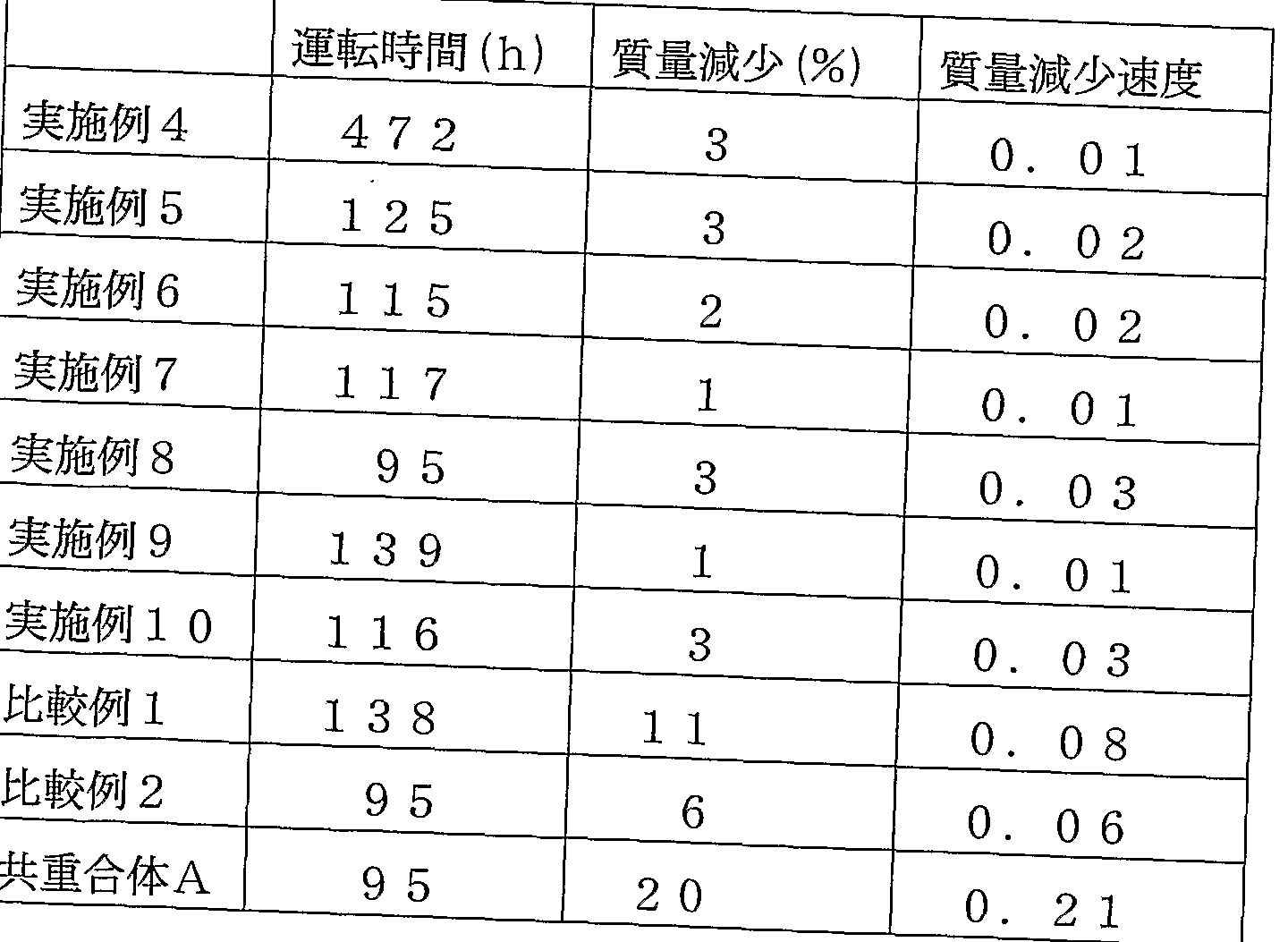
- the durability was evaluated by the following method. With the circuit open, maintain the temperature of the fuel cell at 90 T. Air containing water vapor at a dew point of 5 Ot: on the power source and hydrogen containing water vapor at a dew point of 50 on the anode are each 50 ml Z min. Supplied with After operating in this state for the time shown in the table, the fuel cell was disassembled and the state of deterioration of the electrolyte membrane was measured by mass measurement. The results are shown in the table. Here, the mass reduction rate is the value obtained by dividing the mass reduction (%) by the operation time (h).
- the softening temperature is particularly high particularly when the homopolymer has a softening temperature of 10 ° C. or higher and is composed of a polymer copolymerized using a cyclized polymerizable monomer or a monomer having a ring structure.
- the above-mentioned conventional polymer suddenly starts to decrease in elasticity at around 80 ° C, and its softening temperature is close to the operating temperature of the fuel cell. It is easy to change and has a problem in durability, and it is difficult to operate at temperatures over 80 ° C.
- the electrolyte material of the present invention has a high softening temperature, when used as an electrolyte polymer contained in an electrolyte membrane or an electrode of a fuel cell, there is no change in physical properties over time, and thus high durability can be obtained. It will also be possible to operate the cell at temperatures higher than 80 ° C.
- the electrolyte material for a polymer electrolyte fuel cell of the present invention has an aliphatic ring structure in the main chain, has excellent gas diffusivity, and is highly fluorinated, and thus has excellent water repellency. Excellent durability even when the fuel cell is operated for a long time.
Landscapes
- Chemical & Material Sciences (AREA)
- Chemical Kinetics & Catalysis (AREA)
- Engineering & Computer Science (AREA)
- Manufacturing & Machinery (AREA)
- General Chemical & Material Sciences (AREA)
- Organic Chemistry (AREA)
- Health & Medical Sciences (AREA)
- Sustainable Development (AREA)
- Electrochemistry (AREA)
- Life Sciences & Earth Sciences (AREA)
- Polymers & Plastics (AREA)
- Medicinal Chemistry (AREA)
- Sustainable Energy (AREA)
- Materials Engineering (AREA)
- Inorganic Chemistry (AREA)
- Crystallography & Structural Chemistry (AREA)
- Addition Polymer Or Copolymer, Post-Treatments, Or Chemical Modifications (AREA)
- Fuel Cell (AREA)
- Manufacture Of Macromolecular Shaped Articles (AREA)
- Inert Electrodes (AREA)
Abstract
Description


Claims
Priority Applications (6)
| Application Number | Priority Date | Filing Date | Title |
|---|---|---|---|
| AT04703495T ATE480878T1 (de) | 2003-01-20 | 2004-01-20 | Herstellungsverfahren für elektrolytmaterial für festpolymerbrennstoffzellen und membranelektrodenanordnung für festpolymerbrennstoffzellen |
| EP04703495A EP1596453B1 (en) | 2003-01-20 | 2004-01-20 | Process for production of electrolyte material for solid polymer fuel cells and membrane electrode assembly for solid polymer fuel cells |
| DE602004029011T DE602004029011D1 (de) | 2003-01-20 | 2004-01-20 | Herstellungsverfahren für elektrolytmaterial für festpolymerbrennstoffzellen und membranelektrodenanordnung für festpolymerbrennstoffzellen |
| JP2005508081A JP4677898B2 (ja) | 2003-01-20 | 2004-01-20 | 固体高分子型燃料電池用電解質材料の製造方法及び固体高分子型燃料電池用膜電極接合体 |
| US11/183,748 US7557178B2 (en) | 2003-01-20 | 2005-07-19 | Process for producing electrolyte material for polymer electrolyte fuel cells, and membrane-electrode assembly for polymer electrolyte fuel cells |
| US12/430,961 US8198394B2 (en) | 2003-01-20 | 2009-04-28 | Process for producing electrolyte material for polymer electrolyte fuel cells, and membrane-electrode assembly for polymer electrolyte fuel cells |
Applications Claiming Priority (2)
| Application Number | Priority Date | Filing Date | Title |
|---|---|---|---|
| JP2003011097 | 2003-01-20 | ||
| JP2003-011097 | 2003-01-20 |
Related Child Applications (1)
| Application Number | Title | Priority Date | Filing Date |
|---|---|---|---|
| US11/183,748 Continuation US7557178B2 (en) | 2003-01-20 | 2005-07-19 | Process for producing electrolyte material for polymer electrolyte fuel cells, and membrane-electrode assembly for polymer electrolyte fuel cells |
Publications (1)
| Publication Number | Publication Date |
|---|---|
| WO2004066426A1 true WO2004066426A1 (ja) | 2004-08-05 |
Family
ID=32767269
Family Applications (1)
| Application Number | Title | Priority Date | Filing Date |
|---|---|---|---|
| PCT/JP2004/000404 WO2004066426A1 (ja) | 2003-01-20 | 2004-01-20 | 固体高分子型燃料電池用電解質材料の製造方法及び固体高分子型燃料電池用膜電極接合体 |
Country Status (7)
| Country | Link |
|---|---|
| US (2) | US7557178B2 (ja) |
| EP (1) | EP1596453B1 (ja) |
| JP (1) | JP4677898B2 (ja) |
| CN (1) | CN100389518C (ja) |
| AT (1) | ATE480878T1 (ja) |
| DE (1) | DE602004029011D1 (ja) |
| WO (1) | WO2004066426A1 (ja) |
Cited By (18)
| Publication number | Priority date | Publication date | Assignee | Title |
|---|---|---|---|---|
| JP2004231936A (ja) * | 2002-12-06 | 2004-08-19 | Asahi Glass Co Ltd | テトラフルオロエチレン共重合体、その製造方法およびペースト押し出し成形物 |
| WO2005096422A1 (ja) | 2004-04-02 | 2005-10-13 | Asahi Glass Company, Limited | 固体高分子形燃料電池用電解質材料、電解質膜及び膜電極接合体 |
| JP2006152249A (ja) * | 2004-10-26 | 2006-06-15 | Asahi Glass Co Ltd | フルオロスルホニル基と1,3−ジオキソラン構造を有する重合体およびその用途 |
| JP2007517095A (ja) * | 2003-12-17 | 2007-06-28 | スリーエム イノベイティブ プロパティズ カンパニー | 直接フッ素化により架橋されたポリマー電解質膜 |
| WO2007089017A1 (ja) * | 2006-02-03 | 2007-08-09 | Daikin Industries, Ltd. | -so3h基含有フルオロポリマー製造方法及び-so3h基含有フルオロポリマー |
| JP2007324060A (ja) * | 2006-06-02 | 2007-12-13 | Toyota Motor Corp | フッ素系共重合体を前駆体とする燃料電池用電解質膜、該フッ素系共重合体を前駆体とする燃料電池用電解質膜の製造方法、及び該フッ素系共重合体を前駆体とする電解質膜を有する燃料電池 |
| EP1916237A1 (en) * | 2005-07-27 | 2008-04-30 | Asahi Glass Company, Limited | Compound containing fluorosulfonyl group, process for producing the same, and polymer thereof |
| JPWO2006019097A1 (ja) * | 2004-08-18 | 2008-05-08 | 旭硝子株式会社 | 燃料電池用電解質ポリマー、その製造方法、電解質膜、及び膜・電極接合体 |
| JP2008177167A (ja) * | 2007-01-18 | 2008-07-31 | Asahi Glass Co Ltd | 電解質材料 |
| JP2008308681A (ja) * | 2007-05-16 | 2008-12-25 | Asahi Glass Co Ltd | パーフルオロポリマーの製造方法、製造装置、および固体高分子形燃料電池用電解質膜の製造方法 |
| JP2010506986A (ja) * | 2006-10-17 | 2010-03-04 | ソルヴェイ・ソレクシス・エッセ・ピ・ア | イオン交換基を有するフルオロポリマーを安定化する方法 |
| US7754821B2 (en) * | 2006-02-03 | 2010-07-13 | Daikin Industries Ltd. | Method for producing stabilized fluoropolymer |
| US8198394B2 (en) * | 2003-01-20 | 2012-06-12 | Asahi Glass Company, Limited | Process for producing electrolyte material for polymer electrolyte fuel cells, and membrane-electrode assembly for polymer electrolyte fuel cells |
| JP2014500392A (ja) * | 2010-12-20 | 2014-01-09 | イー・アイ・デュポン・ドウ・ヌムール・アンド・カンパニー | アイオノマー及びイオン伝導性組成物 |
| WO2017038827A1 (ja) * | 2015-08-31 | 2017-03-09 | 旭硝子株式会社 | 液状組成物の製造方法、触媒層形成用塗工液の製造方法および膜電極接合体の製造方法 |
| WO2017038824A1 (ja) * | 2015-08-31 | 2017-03-09 | 旭硝子株式会社 | 液状組成物の製造方法、触媒層形成用塗工液の製造方法および膜電極接合体の製造方法 |
| CN115991830A (zh) * | 2021-10-18 | 2023-04-21 | 山东东岳未来氢能材料股份有限公司 | 耐高温功能聚合物 |
| WO2023136243A1 (ja) * | 2022-01-11 | 2023-07-20 | 日東電工株式会社 | フッ素樹脂の精製方法、精製されたフッ素樹脂の製造方法、フッ素樹脂、光学材料、電子材料及びプラスチック光ファイバ |
Families Citing this family (20)
| Publication number | Priority date | Publication date | Assignee | Title |
|---|---|---|---|---|
| WO2004102714A1 (ja) | 2003-05-13 | 2004-11-25 | Asahi Glass Company, Limited | 固体高分子型燃料電池用電解質ポリマー、その製造方法及び膜・電極接合体 |
| US20050037265A1 (en) * | 2003-08-14 | 2005-02-17 | Asahi Glass Company, Limited | Polymer electrolyte fuel cell, electrolyte material therefore and method for its production |
| US20070129500A1 (en) | 2003-09-10 | 2007-06-07 | Eiji Honda | Stabilized fluoropolymer and method for producing same |
| KR20070106200A (ko) * | 2006-04-28 | 2007-11-01 | 삼성에스디아이 주식회사 | 연료전지용 막-전극 어셈블리, 이의 제조방법 및 이를포함하는 연료전지 시스템 |
| US8017257B2 (en) * | 2007-01-26 | 2011-09-13 | Asahi Glass Company, Limited | Polymer, polymer electrolyte membrane for polymer electrolyte fuel cell, and membrane/electrode assembly |
| JP2008210793A (ja) | 2007-01-30 | 2008-09-11 | Asahi Glass Co Ltd | 固体高分子形燃料電池用膜電極接合体および固体高分子形燃料電池の運転方法 |
| KR100978609B1 (ko) | 2007-11-27 | 2010-08-27 | 한양대학교 산학협력단 | 불소가스를 이용한 직접불소화법에 의해 표면처리된수소이온전도성 고분자막, 이를 포함하는 막-전극 어셈블리및 연료전지 |
| US20110027687A1 (en) * | 2009-07-31 | 2011-02-03 | Asahi Glass Company, Limited | Electrolyte material, liquid composition and membrane/electrode assembly for polymer electrolyte fuel cell |
| JP5660879B2 (ja) | 2010-12-20 | 2015-01-28 | トヨタ自動車株式会社 | カソード側触媒層、膜電極接合体、固体高分子型燃料電池及びその製造方法 |
| EP2656425B1 (en) * | 2010-12-20 | 2014-12-10 | E.I. Du Pont De Nemours And Company | Ionomers and ionically conductive compositions for use as one or more electrode of a fuel cell |
| CN104220467B (zh) * | 2012-04-16 | 2017-08-04 | 旭硝子株式会社 | 电解质材料、液状组合物及固体高分子型燃料电池用膜电极接合体 |
| JP6151501B2 (ja) * | 2012-10-01 | 2017-06-21 | 旭化成株式会社 | 高分子電解質含有溶液及び固体高分子電解質膜の製造方法 |
| EP2722350A1 (en) * | 2012-10-19 | 2014-04-23 | Solvay Specialty Polymers Italy S.p.A. | Amorphous fluorinated polymer |
| US8906572B2 (en) | 2012-11-30 | 2014-12-09 | General Electric Company | Polymer-electrolyte membrane, electrochemical fuel cell, and related method |
| WO2015098769A1 (ja) * | 2013-12-25 | 2015-07-02 | 旭硝子株式会社 | フッ素系陽イオン交換膜の製造方法 |
| WO2018070420A1 (ja) | 2016-10-14 | 2018-04-19 | ダイキン工業株式会社 | 含フッ素ポリマーの粉体及びその製造方法 |
| EP3858873A4 (en) * | 2018-09-28 | 2022-06-29 | Tosoh Corporation | Fluororesin, fluororesin particles, and methods for producing these |
| CN113346132B (zh) * | 2021-05-24 | 2023-03-10 | 上海大学 | 一种氟化聚环氧乙烷固态电解质材料及其制备方法和应用 |
| KR20230026568A (ko) * | 2021-08-17 | 2023-02-27 | 한양대학교 산학협력단 | 전고체전지용 양극 및 이를 포함하는 전고체전지 |
| CN116364991B (zh) * | 2023-05-31 | 2023-08-18 | 安徽明天新能源科技有限公司 | 一种催化层涂覆膜及其制备方法 |
Citations (5)
| Publication number | Priority date | Publication date | Assignee | Title |
|---|---|---|---|---|
| JP2001357858A (ja) * | 2000-06-14 | 2001-12-26 | Asahi Glass Co Ltd | 固体高分子型燃料電池 |
| JP2002216804A (ja) * | 2000-02-15 | 2002-08-02 | Asahi Glass Co Ltd | 固体高分子型燃料電池 |
| JP2002231268A (ja) * | 2001-01-26 | 2002-08-16 | Asahi Glass Co Ltd | 固体高分子型燃料電池用電解質材料及び固体高分子型燃料電池 |
| JP2002260705A (ja) * | 2000-12-26 | 2002-09-13 | Asahi Glass Co Ltd | 固体高分子電解質材料、液状組成物、固体高分子型燃料電池、含フッ素ポリマー及び含フッ素ポリマーからなる固体高分子電解質膜 |
| JP2003321558A (ja) * | 2002-02-27 | 2003-11-14 | Asahi Kasei Corp | 高分子膜の製造法 |
Family Cites Families (21)
| Publication number | Priority date | Publication date | Assignee | Title |
|---|---|---|---|---|
| FR1600355A (ja) | 1968-01-18 | 1970-07-20 | ||
| EP0645406B1 (en) | 1988-05-31 | 2001-04-11 | E.I. Du Pont De Nemours And Company | Amorphous copolymers of perfluoro-2,2-dimethyl-1,3-dioxole |
| JPH0536418A (ja) | 1991-03-13 | 1993-02-12 | Fuji Electric Co Ltd | 固体高分子電解質型燃料電池およびその製造方法 |
| JP3245929B2 (ja) | 1992-03-09 | 2002-01-15 | 株式会社日立製作所 | 燃料電池及びその応用装置 |
| US5399184A (en) * | 1992-05-01 | 1995-03-21 | Chlorine Engineers Corp., Ltd. | Method for fabricating gas diffusion electrode assembly for fuel cells |
| JP3331703B2 (ja) | 1993-11-09 | 2002-10-07 | 株式会社豊田中央研究所 | 燃料電池 |
| JPH07192738A (ja) | 1993-12-24 | 1995-07-28 | Toshiba Corp | 燃料電池用電極触媒層 |
| JPH07211324A (ja) | 1994-01-19 | 1995-08-11 | Osaka Gas Co Ltd | 電極触媒組成物、電極材およびその製造方法 |
| JP4150867B2 (ja) * | 1998-05-13 | 2008-09-17 | ダイキン工業株式会社 | 燃料電池に使用するのに適した固体高分子電解質用材料 |
| CN1337072A (zh) | 1998-12-22 | 2002-02-20 | 戴维系统技术公司 | 膜电极组件及其生产方法 |
| DE60143635D1 (de) | 2000-02-15 | 2011-01-27 | Asahi Glass Co Ltd | Blockpolymer, Verfahren zur Herstellung von Polymer und Festpolymerelektrolytbrennstoffzelle |
| US6492295B2 (en) * | 2000-03-15 | 2002-12-10 | Japan Storage Battery Co., Ltd. | Composite catalyst for solid polymer electrolyte type fuel cell and processes for producing the same |
| JP2001283866A (ja) * | 2000-03-31 | 2001-10-12 | Japan Storage Battery Co Ltd | 燃料電池用ガス拡散電極およびその製造方法 |
| DE60135080D1 (de) * | 2000-12-26 | 2008-09-11 | Asahi Glass Co Ltd | Festpolymer-Elektrolyt Material, flüssige Zusammensetzung, Festpolymer Brennstoffzelle und Fluorpolymer |
| RU2196789C2 (ru) | 2001-02-07 | 2003-01-20 | Открытое акционерное общество "Пластполимер" (ОАО "Пластполимер") | Жидкая композиция на основе перфторированного ионообменного сополимера |
| ITMI20010921A1 (it) | 2001-05-07 | 2002-11-07 | Ausimont Spa | Polimeri (per)fluorurati amorfi |
| JP5105340B2 (ja) * | 2001-05-23 | 2012-12-26 | 独立行政法人日本原子力研究開発機構 | 広いイオン交換容量を有するフッ素系高分子イオン交換膜及びその製造方法 |
| JP4492121B2 (ja) | 2001-10-30 | 2010-06-30 | 旭硝子株式会社 | フルオロスルホニル基含有化合物および該化合物から誘導される化合物の製造方法 |
| JP2004085713A (ja) * | 2002-08-23 | 2004-03-18 | Asahi Glass Co Ltd | ペリクル |
| WO2004066426A1 (ja) * | 2003-01-20 | 2004-08-05 | Asahi Glass Company, Limited | 固体高分子型燃料電池用電解質材料の製造方法及び固体高分子型燃料電池用膜電極接合体 |
| US20050037265A1 (en) | 2003-08-14 | 2005-02-17 | Asahi Glass Company, Limited | Polymer electrolyte fuel cell, electrolyte material therefore and method for its production |
-
2004
- 2004-01-20 WO PCT/JP2004/000404 patent/WO2004066426A1/ja active Application Filing
- 2004-01-20 CN CNB2004800023953A patent/CN100389518C/zh not_active Expired - Fee Related
- 2004-01-20 EP EP04703495A patent/EP1596453B1/en not_active Revoked
- 2004-01-20 AT AT04703495T patent/ATE480878T1/de not_active IP Right Cessation
- 2004-01-20 JP JP2005508081A patent/JP4677898B2/ja not_active Expired - Lifetime
- 2004-01-20 DE DE602004029011T patent/DE602004029011D1/de not_active Expired - Lifetime
-
2005
- 2005-07-19 US US11/183,748 patent/US7557178B2/en active Active
-
2009
- 2009-04-28 US US12/430,961 patent/US8198394B2/en not_active Expired - Fee Related
Patent Citations (5)
| Publication number | Priority date | Publication date | Assignee | Title |
|---|---|---|---|---|
| JP2002216804A (ja) * | 2000-02-15 | 2002-08-02 | Asahi Glass Co Ltd | 固体高分子型燃料電池 |
| JP2001357858A (ja) * | 2000-06-14 | 2001-12-26 | Asahi Glass Co Ltd | 固体高分子型燃料電池 |
| JP2002260705A (ja) * | 2000-12-26 | 2002-09-13 | Asahi Glass Co Ltd | 固体高分子電解質材料、液状組成物、固体高分子型燃料電池、含フッ素ポリマー及び含フッ素ポリマーからなる固体高分子電解質膜 |
| JP2002231268A (ja) * | 2001-01-26 | 2002-08-16 | Asahi Glass Co Ltd | 固体高分子型燃料電池用電解質材料及び固体高分子型燃料電池 |
| JP2003321558A (ja) * | 2002-02-27 | 2003-11-14 | Asahi Kasei Corp | 高分子膜の製造法 |
Cited By (36)
| Publication number | Priority date | Publication date | Assignee | Title |
|---|---|---|---|---|
| JP2004231936A (ja) * | 2002-12-06 | 2004-08-19 | Asahi Glass Co Ltd | テトラフルオロエチレン共重合体、その製造方法およびペースト押し出し成形物 |
| US8198394B2 (en) * | 2003-01-20 | 2012-06-12 | Asahi Glass Company, Limited | Process for producing electrolyte material for polymer electrolyte fuel cells, and membrane-electrode assembly for polymer electrolyte fuel cells |
| JP2007517095A (ja) * | 2003-12-17 | 2007-06-28 | スリーエム イノベイティブ プロパティズ カンパニー | 直接フッ素化により架橋されたポリマー電解質膜 |
| EP1734603A1 (en) * | 2004-04-02 | 2006-12-20 | Asahi Glass Company, Limited | Electrolyte material for solid polymer type fuel cell, electrolyte membrane and membrane electrode assembly |
| US7799468B2 (en) | 2004-04-02 | 2010-09-21 | Asahi Glass Company, Limited | Electrolyte material for polymer electrolyte fuel cells, electrolyte membrane and membrane-electrode assembly |
| WO2005096422A1 (ja) | 2004-04-02 | 2005-10-13 | Asahi Glass Company, Limited | 固体高分子形燃料電池用電解質材料、電解質膜及び膜電極接合体 |
| EP1734603A4 (en) * | 2004-04-02 | 2008-09-03 | Asahi Glass Co Ltd | ELECTROLYTE FOR SOLID POLYMER TYPE FUEL CELL, ELECTROLYTE MEMBRANE, AND MEMBRANE ELECTRODE ASSEMBLY |
| JPWO2006019097A1 (ja) * | 2004-08-18 | 2008-05-08 | 旭硝子株式会社 | 燃料電池用電解質ポリマー、その製造方法、電解質膜、及び膜・電極接合体 |
| JP5168903B2 (ja) * | 2004-08-18 | 2013-03-27 | 旭硝子株式会社 | 燃料電池用電解質ポリマー、その製造方法、電解質膜、及び膜・電極接合体 |
| JP2006152249A (ja) * | 2004-10-26 | 2006-06-15 | Asahi Glass Co Ltd | フルオロスルホニル基と1,3−ジオキソラン構造を有する重合体およびその用途 |
| US7667083B2 (en) | 2005-07-27 | 2010-02-23 | Asahi Glass Company, Limited | Fluorosulfonyl group-containing compound, method for its production and polymer thereof |
| EP1916237A1 (en) * | 2005-07-27 | 2008-04-30 | Asahi Glass Company, Limited | Compound containing fluorosulfonyl group, process for producing the same, and polymer thereof |
| EP1916237A4 (en) * | 2005-07-27 | 2008-11-26 | Asahi Glass Co Ltd | A COMPOSITION CONTAINING A FLUORESULFONYL GROUP, METHOD FOR THE PRODUCTION THEREOF AND POLYMER THEREOF |
| US7531610B2 (en) | 2005-07-27 | 2009-05-12 | Asahi Glass Company, Limited | Fluorosulfonyl group-containing compound, method for its production and polymer thereof |
| WO2007089017A1 (ja) * | 2006-02-03 | 2007-08-09 | Daikin Industries, Ltd. | -so3h基含有フルオロポリマー製造方法及び-so3h基含有フルオロポリマー |
| US7754821B2 (en) * | 2006-02-03 | 2010-07-13 | Daikin Industries Ltd. | Method for producing stabilized fluoropolymer |
| US7776970B2 (en) | 2006-02-03 | 2010-08-17 | Daikin Industries, Ltd. | Method for producing -SO3H group-containing fluoropolymer and -SO3H group-containing fluoropolymer |
| US8034880B2 (en) | 2006-02-03 | 2011-10-11 | Daikin Industries, Ltd. | Method for producing—SO3H group-containing fluoropolymer and—SO3H group-containing fluoropolymer |
| JP2007324060A (ja) * | 2006-06-02 | 2007-12-13 | Toyota Motor Corp | フッ素系共重合体を前駆体とする燃料電池用電解質膜、該フッ素系共重合体を前駆体とする燃料電池用電解質膜の製造方法、及び該フッ素系共重合体を前駆体とする電解質膜を有する燃料電池 |
| JP2010506986A (ja) * | 2006-10-17 | 2010-03-04 | ソルヴェイ・ソレクシス・エッセ・ピ・ア | イオン交換基を有するフルオロポリマーを安定化する方法 |
| JP2008177167A (ja) * | 2007-01-18 | 2008-07-31 | Asahi Glass Co Ltd | 電解質材料 |
| JP2008308681A (ja) * | 2007-05-16 | 2008-12-25 | Asahi Glass Co Ltd | パーフルオロポリマーの製造方法、製造装置、および固体高分子形燃料電池用電解質膜の製造方法 |
| JP2014500392A (ja) * | 2010-12-20 | 2014-01-09 | イー・アイ・デュポン・ドウ・ヌムール・アンド・カンパニー | アイオノマー及びイオン伝導性組成物 |
| US10461336B2 (en) | 2015-08-31 | 2019-10-29 | AGC Inc. | Process for producing liquid composition and process for producing catalyst layer-forming coating liquid |
| WO2017038824A1 (ja) * | 2015-08-31 | 2017-03-09 | 旭硝子株式会社 | 液状組成物の製造方法、触媒層形成用塗工液の製造方法および膜電極接合体の製造方法 |
| JPWO2017038827A1 (ja) * | 2015-08-31 | 2018-06-28 | 旭硝子株式会社 | 液状組成物の製造方法、触媒層形成用塗工液の製造方法および膜電極接合体の製造方法 |
| JPWO2017038824A1 (ja) * | 2015-08-31 | 2018-07-26 | 旭硝子株式会社 | 液状組成物の製造方法、触媒層形成用塗工液の製造方法および膜電極接合体の製造方法 |
| WO2017038827A1 (ja) * | 2015-08-31 | 2017-03-09 | 旭硝子株式会社 | 液状組成物の製造方法、触媒層形成用塗工液の製造方法および膜電極接合体の製造方法 |
| US10457760B2 (en) | 2015-08-31 | 2019-10-29 | AGC Inc. | Process for producing liquid composition and process for producing catalyst layer-forming coating liquid |
| CN115991830A (zh) * | 2021-10-18 | 2023-04-21 | 山东东岳未来氢能材料股份有限公司 | 耐高温功能聚合物 |
| CN115991823A (zh) * | 2021-10-18 | 2023-04-21 | 山东东岳未来氢能材料股份有限公司 | 混合型全氟质子交换膜及其制备方法 |
| CN115991824A (zh) * | 2021-10-18 | 2023-04-21 | 山东东岳未来氢能材料股份有限公司 | 含环状结构单元的质子交换膜及制备方法 |
| CN115991824B (zh) * | 2021-10-18 | 2023-12-22 | 山东东岳未来氢能材料股份有限公司 | 含环状结构单元的质子交换膜及制备方法 |
| CN115991823B (zh) * | 2021-10-18 | 2023-12-29 | 山东东岳未来氢能材料股份有限公司 | 混合型全氟质子交换膜及其制备方法 |
| CN115991830B (zh) * | 2021-10-18 | 2024-01-05 | 山东东岳未来氢能材料股份有限公司 | 耐高温功能聚合物 |
| WO2023136243A1 (ja) * | 2022-01-11 | 2023-07-20 | 日東電工株式会社 | フッ素樹脂の精製方法、精製されたフッ素樹脂の製造方法、フッ素樹脂、光学材料、電子材料及びプラスチック光ファイバ |
Also Published As
| Publication number | Publication date |
|---|---|
| CN1739216A (zh) | 2006-02-22 |
| EP1596453A1 (en) | 2005-11-16 |
| EP1596453A4 (en) | 2008-08-27 |
| JPWO2004066426A1 (ja) | 2006-05-18 |
| DE602004029011D1 (de) | 2010-10-21 |
| CN100389518C (zh) | 2008-05-21 |
| US20090215938A1 (en) | 2009-08-27 |
| US7557178B2 (en) | 2009-07-07 |
| ATE480878T1 (de) | 2010-09-15 |
| JP4677898B2 (ja) | 2011-04-27 |
| US8198394B2 (en) | 2012-06-12 |
| EP1596453B1 (en) | 2010-09-08 |
| US20060287497A1 (en) | 2006-12-21 |
Similar Documents
| Publication | Publication Date | Title |
|---|---|---|
| WO2004066426A1 (ja) | 固体高分子型燃料電池用電解質材料の製造方法及び固体高分子型燃料電池用膜電極接合体 | |
| US7429428B2 (en) | Polymer electrolyte material, production method thereof and membrane electrode assembly for polymer electrolyte fuel cell | |
| EP1914824B1 (en) | Electrolyte material for solid polymer fuel cell, electrolyte membrane and membrane-electrode assembly | |
| US7220508B2 (en) | Solid polymer electrolyte material, liquid composition, solid polymer fuel cell and fluoropolymer | |
| JP4032738B2 (ja) | 固体高分子電解質材料、液状組成物、固体高分子型燃料電池、含フッ素ポリマー及び含フッ素ポリマーからなる固体高分子電解質膜 | |
| JP5286797B2 (ja) | ポリマー、固体高分子形燃料電池用固体高分子電解質膜および膜電極接合体 | |
| JP6172142B2 (ja) | 電解質材料、液状組成物および固体高分子形燃料電池用膜電極接合体 | |
| JP5499478B2 (ja) | ポリマー、固体高分子形燃料電池用固体高分子電解質膜および膜電極接合体 | |
| CN107108781B (zh) | 电解质材料、液态组合物以及固体高分子型燃料电池用膜电极接合体 | |
| JP4910269B2 (ja) | 固体高分子型燃料電池用電解質材料、その製造方法及び固体高分子型燃料電池用膜電極接合体 | |
| JP2002216804A (ja) | 固体高分子型燃料電池 | |
| EP1927601B1 (en) | Polymer, polymer electrolyte membrane for polymer electrolyte fuel cell, and membrane/electrode assembly | |
| JP4848587B2 (ja) | 固体高分子型燃料電池用電解質材料とその製造方法、及び固体高分子型燃料電池 | |
| EP1968147A2 (en) | Membrane/electrode assembly for polymer electrolyte fuel cells, and method for operating polymer electrolyte fuel cell |
Legal Events
| Date | Code | Title | Description |
|---|---|---|---|
| AK | Designated states |
Kind code of ref document: A1 Designated state(s): AE AG AL AM AT AU AZ BA BB BG BR BW BY BZ CA CH CN CO CR CU CZ DE DK DM DZ EC EE EG ES FI GB GD GE GH GM HR HU ID IL IN IS JP KE KG KP KR KZ LC LK LR LS LT LU LV MA MD MG MK MN MW MX MZ NA NI NO NZ OM PG PH PL PT RO RU SC SD SE SG SK SL SY TJ TM TN TR TT TZ UA UG US UZ VC VN YU ZA ZM ZW |
|
| AL | Designated countries for regional patents |
Kind code of ref document: A1 Designated state(s): BW GH GM KE LS MW MZ SD SL SZ TZ UG ZM ZW AM AZ BY KG KZ MD RU TJ TM AT BE BG CH CY CZ DE DK EE ES FI FR GB GR HU IE IT LU MC NL PT RO SE SI SK TR BF BJ CF CG CI CM GA GN GQ GW ML MR NE SN TD TG |
|
| 121 | Ep: the epo has been informed by wipo that ep was designated in this application | ||
| WWE | Wipo information: entry into national phase |
Ref document number: 2005508081 Country of ref document: JP |
|
| WWE | Wipo information: entry into national phase |
Ref document number: 20048023953 Country of ref document: CN |
|
| WWE | Wipo information: entry into national phase |
Ref document number: 11183748 Country of ref document: US |
|
| WWE | Wipo information: entry into national phase |
Ref document number: 2004703495 Country of ref document: EP |
|
| WWP | Wipo information: published in national office |
Ref document number: 2004703495 Country of ref document: EP |
|
| WWP | Wipo information: published in national office |
Ref document number: 11183748 Country of ref document: US |