JP3918794B2 - 圧電発振器およびその製造方法並びに電子機器 - Google Patents
圧電発振器およびその製造方法並びに電子機器 Download PDFInfo
- Publication number
- JP3918794B2 JP3918794B2 JP2003334616A JP2003334616A JP3918794B2 JP 3918794 B2 JP3918794 B2 JP 3918794B2 JP 2003334616 A JP2003334616 A JP 2003334616A JP 2003334616 A JP2003334616 A JP 2003334616A JP 3918794 B2 JP3918794 B2 JP 3918794B2
- Authority
- JP
- Japan
- Prior art keywords
- lead frame
- pad
- mounting
- piezoelectric
- terminal
- Prior art date
- Legal status (The legal status is an assumption and is not a legal conclusion. Google has not performed a legal analysis and makes no representation as to the accuracy of the status listed.)
- Expired - Lifetime
Links
- 238000004519 manufacturing process Methods 0.000 title claims description 20
- 239000011347 resin Substances 0.000 claims description 183
- 229920005989 resin Polymers 0.000 claims description 183
- 238000000034 method Methods 0.000 claims description 25
- 230000010355 oscillation Effects 0.000 claims description 15
- 238000007789 sealing Methods 0.000 claims description 13
- 230000008569 process Effects 0.000 claims description 9
- 238000003825 pressing Methods 0.000 claims description 7
- 238000010030 laminating Methods 0.000 claims description 5
- 239000000758 substrate Substances 0.000 description 38
- 229910000679 solder Inorganic materials 0.000 description 31
- 230000004048 modification Effects 0.000 description 21
- 238000012986 modification Methods 0.000 description 21
- 238000005520 cutting process Methods 0.000 description 11
- 238000000465 moulding Methods 0.000 description 11
- 230000000694 effects Effects 0.000 description 10
- 238000007747 plating Methods 0.000 description 9
- 238000005452 bending Methods 0.000 description 8
- 230000005284 excitation Effects 0.000 description 8
- 238000010586 diagram Methods 0.000 description 7
- 230000006870 function Effects 0.000 description 7
- 230000001788 irregular Effects 0.000 description 7
- 239000002184 metal Substances 0.000 description 7
- 238000005530 etching Methods 0.000 description 6
- 239000000523 sample Substances 0.000 description 6
- 239000000853 adhesive Substances 0.000 description 5
- 230000001070 adhesive effect Effects 0.000 description 5
- 230000002950 deficient Effects 0.000 description 5
- 238000007689 inspection Methods 0.000 description 4
- 239000000126 substance Substances 0.000 description 4
- 230000001413 cellular effect Effects 0.000 description 3
- 230000008859 change Effects 0.000 description 3
- 238000012790 confirmation Methods 0.000 description 3
- 239000000428 dust Substances 0.000 description 3
- 238000005304 joining Methods 0.000 description 3
- 238000012545 processing Methods 0.000 description 3
- 125000006850 spacer group Chemical group 0.000 description 3
- 238000003466 welding Methods 0.000 description 3
- 241000272168 Laridae Species 0.000 description 2
- 235000014676 Phragmites communis Nutrition 0.000 description 2
- 230000005540 biological transmission Effects 0.000 description 2
- 239000003990 capacitor Substances 0.000 description 2
- 239000000919 ceramic Substances 0.000 description 2
- 239000011521 glass Substances 0.000 description 2
- 238000001746 injection moulding Methods 0.000 description 2
- 238000002844 melting Methods 0.000 description 2
- 239000004593 Epoxy Substances 0.000 description 1
- 244000089486 Phragmites australis subsp australis Species 0.000 description 1
- XUIMIQQOPSSXEZ-UHFFFAOYSA-N Silicon Chemical compound [Si] XUIMIQQOPSSXEZ-UHFFFAOYSA-N 0.000 description 1
- 239000012298 atmosphere Substances 0.000 description 1
- 239000005388 borosilicate glass Substances 0.000 description 1
- 229910010293 ceramic material Inorganic materials 0.000 description 1
- 238000004891 communication Methods 0.000 description 1
- 239000013078 crystal Substances 0.000 description 1
- 230000003247 decreasing effect Effects 0.000 description 1
- 230000007547 defect Effects 0.000 description 1
- 238000005553 drilling Methods 0.000 description 1
- 238000010304 firing Methods 0.000 description 1
- 238000002347 injection Methods 0.000 description 1
- 239000007924 injection Substances 0.000 description 1
- 230000001678 irradiating effect Effects 0.000 description 1
- 239000007788 liquid Substances 0.000 description 1
- 239000004973 liquid crystal related substance Substances 0.000 description 1
- 230000000873 masking effect Effects 0.000 description 1
- 239000000463 material Substances 0.000 description 1
- 230000008018 melting Effects 0.000 description 1
- 239000012299 nitrogen atmosphere Substances 0.000 description 1
- 230000000149 penetrating effect Effects 0.000 description 1
- 230000002093 peripheral effect Effects 0.000 description 1
- 230000002265 prevention Effects 0.000 description 1
- 239000010453 quartz Substances 0.000 description 1
- 230000009467 reduction Effects 0.000 description 1
- 230000035945 sensitivity Effects 0.000 description 1
- 238000000926 separation method Methods 0.000 description 1
- 229910052710 silicon Inorganic materials 0.000 description 1
- 239000010703 silicon Substances 0.000 description 1
- VYPSYNLAJGMNEJ-UHFFFAOYSA-N silicon dioxide Inorganic materials O=[Si]=O VYPSYNLAJGMNEJ-UHFFFAOYSA-N 0.000 description 1
- 230000005236 sound signal Effects 0.000 description 1
- 238000005507 spraying Methods 0.000 description 1
- 238000003860 storage Methods 0.000 description 1
- 229920001187 thermosetting polymer Polymers 0.000 description 1
- XLYOFNOQVPJJNP-UHFFFAOYSA-N water Substances O XLYOFNOQVPJJNP-UHFFFAOYSA-N 0.000 description 1
Images


Classifications
-
- H—ELECTRICITY
- H03—ELECTRONIC CIRCUITRY
- H03H—IMPEDANCE NETWORKS, e.g. RESONANT CIRCUITS; RESONATORS
- H03H9/00—Networks comprising electromechanical or electro-acoustic devices; Electromechanical resonators
- H03H9/02—Details
- H03H9/05—Holders; Supports
- H03H9/10—Mounting in enclosures
- H03H9/1007—Mounting in enclosures for bulk acoustic wave [BAW] devices
- H03H9/1014—Mounting in enclosures for bulk acoustic wave [BAW] devices the enclosure being defined by a frame built on a substrate and a cap, the frame having no mechanical contact with the BAW device
-
- H—ELECTRICITY
- H03—ELECTRONIC CIRCUITRY
- H03H—IMPEDANCE NETWORKS, e.g. RESONANT CIRCUITS; RESONATORS
- H03H9/00—Networks comprising electromechanical or electro-acoustic devices; Electromechanical resonators
- H03H9/02—Details
- H03H9/05—Holders; Supports
- H03H9/0538—Constructional combinations of supports or holders with electromechanical or other electronic elements
- H03H9/0547—Constructional combinations of supports or holders with electromechanical or other electronic elements consisting of a vertical arrangement
-
- H—ELECTRICITY
- H03—ELECTRONIC CIRCUITRY
- H03H—IMPEDANCE NETWORKS, e.g. RESONANT CIRCUITS; RESONATORS
- H03H9/00—Networks comprising electromechanical or electro-acoustic devices; Electromechanical resonators
- H03H9/02—Details
- H03H9/05—Holders; Supports
- H03H9/10—Mounting in enclosures
- H03H9/1007—Mounting in enclosures for bulk acoustic wave [BAW] devices
- H03H9/1014—Mounting in enclosures for bulk acoustic wave [BAW] devices the enclosure being defined by a frame built on a substrate and a cap, the frame having no mechanical contact with the BAW device
- H03H9/1021—Mounting in enclosures for bulk acoustic wave [BAW] devices the enclosure being defined by a frame built on a substrate and a cap, the frame having no mechanical contact with the BAW device the BAW device being of the cantilever type
-
- H—ELECTRICITY
- H01—ELECTRIC ELEMENTS
- H01L—SEMICONDUCTOR DEVICES NOT COVERED BY CLASS H10
- H01L2224/00—Indexing scheme for arrangements for connecting or disconnecting semiconductor or solid-state bodies and methods related thereto as covered by H01L24/00
- H01L2224/01—Means for bonding being attached to, or being formed on, the surface to be connected, e.g. chip-to-package, die-attach, "first-level" interconnects; Manufacturing methods related thereto
- H01L2224/42—Wire connectors; Manufacturing methods related thereto
- H01L2224/47—Structure, shape, material or disposition of the wire connectors after the connecting process
- H01L2224/48—Structure, shape, material or disposition of the wire connectors after the connecting process of an individual wire connector
- H01L2224/4805—Shape
- H01L2224/4809—Loop shape
- H01L2224/48091—Arched
-
- H—ELECTRICITY
- H01—ELECTRIC ELEMENTS
- H01L—SEMICONDUCTOR DEVICES NOT COVERED BY CLASS H10
- H01L2224/00—Indexing scheme for arrangements for connecting or disconnecting semiconductor or solid-state bodies and methods related thereto as covered by H01L24/00
- H01L2224/01—Means for bonding being attached to, or being formed on, the surface to be connected, e.g. chip-to-package, die-attach, "first-level" interconnects; Manufacturing methods related thereto
- H01L2224/42—Wire connectors; Manufacturing methods related thereto
- H01L2224/47—Structure, shape, material or disposition of the wire connectors after the connecting process
- H01L2224/48—Structure, shape, material or disposition of the wire connectors after the connecting process of an individual wire connector
- H01L2224/481—Disposition
- H01L2224/48151—Connecting between a semiconductor or solid-state body and an item not being a semiconductor or solid-state body, e.g. chip-to-substrate, chip-to-passive
- H01L2224/48221—Connecting between a semiconductor or solid-state body and an item not being a semiconductor or solid-state body, e.g. chip-to-substrate, chip-to-passive the body and the item being stacked
- H01L2224/48245—Connecting between a semiconductor or solid-state body and an item not being a semiconductor or solid-state body, e.g. chip-to-substrate, chip-to-passive the body and the item being stacked the item being metallic
- H01L2224/48247—Connecting between a semiconductor or solid-state body and an item not being a semiconductor or solid-state body, e.g. chip-to-substrate, chip-to-passive the body and the item being stacked the item being metallic connecting the wire to a bond pad of the item
-
- H—ELECTRICITY
- H01—ELECTRIC ELEMENTS
- H01L—SEMICONDUCTOR DEVICES NOT COVERED BY CLASS H10
- H01L2224/00—Indexing scheme for arrangements for connecting or disconnecting semiconductor or solid-state bodies and methods related thereto as covered by H01L24/00
- H01L2224/01—Means for bonding being attached to, or being formed on, the surface to be connected, e.g. chip-to-package, die-attach, "first-level" interconnects; Manufacturing methods related thereto
- H01L2224/42—Wire connectors; Manufacturing methods related thereto
- H01L2224/47—Structure, shape, material or disposition of the wire connectors after the connecting process
- H01L2224/49—Structure, shape, material or disposition of the wire connectors after the connecting process of a plurality of wire connectors
- H01L2224/491—Disposition
- H01L2224/49105—Connecting at different heights
- H01L2224/49109—Connecting at different heights outside the semiconductor or solid-state body
-
- H—ELECTRICITY
- H01—ELECTRIC ELEMENTS
- H01L—SEMICONDUCTOR DEVICES NOT COVERED BY CLASS H10
- H01L2924/00—Indexing scheme for arrangements or methods for connecting or disconnecting semiconductor or solid-state bodies as covered by H01L24/00
- H01L2924/01—Chemical elements
- H01L2924/01077—Iridium [Ir]
-
- H—ELECTRICITY
- H01—ELECTRIC ELEMENTS
- H01L—SEMICONDUCTOR DEVICES NOT COVERED BY CLASS H10
- H01L2924/00—Indexing scheme for arrangements or methods for connecting or disconnecting semiconductor or solid-state bodies as covered by H01L24/00
- H01L2924/01—Chemical elements
- H01L2924/01078—Platinum [Pt]
-
- H—ELECTRICITY
- H01—ELECTRIC ELEMENTS
- H01L—SEMICONDUCTOR DEVICES NOT COVERED BY CLASS H10
- H01L2924/00—Indexing scheme for arrangements or methods for connecting or disconnecting semiconductor or solid-state bodies as covered by H01L24/00
- H01L2924/15—Details of package parts other than the semiconductor or other solid state devices to be connected
- H01L2924/151—Die mounting substrate
- H01L2924/153—Connection portion
- H01L2924/1532—Connection portion the connection portion being formed on the die mounting surface of the substrate
-
- H—ELECTRICITY
- H01—ELECTRIC ELEMENTS
- H01L—SEMICONDUCTOR DEVICES NOT COVERED BY CLASS H10
- H01L2924/00—Indexing scheme for arrangements or methods for connecting or disconnecting semiconductor or solid-state bodies as covered by H01L24/00
- H01L2924/15—Details of package parts other than the semiconductor or other solid state devices to be connected
- H01L2924/181—Encapsulation
-
- H—ELECTRICITY
- H01—ELECTRIC ELEMENTS
- H01L—SEMICONDUCTOR DEVICES NOT COVERED BY CLASS H10
- H01L2924/00—Indexing scheme for arrangements or methods for connecting or disconnecting semiconductor or solid-state bodies as covered by H01L24/00
- H01L2924/19—Details of hybrid assemblies other than the semiconductor or other solid state devices to be connected
- H01L2924/1901—Structure
- H01L2924/1904—Component type
- H01L2924/19041—Component type being a capacitor
Description
なお特許文献2にも同様の構成が示されている。
そこで本発明は、平面サイズを小さくすることにより小型化を可能にすることを目的とする。
また、本発明は、接合強度を向上させることを目的としている。
さらに、本発明は、実装強度を向上させることを目的としている。
この場合において、前記上側リードフレームの前記第1のパッドと前記ICとは、ワイヤによって接続されており、前記第1の傾斜部は、ボンディングされた前記ワイヤの最大高さよりも大きく立ち上げて形成してあることを特徴としている。
本発明は、圧電振動片と、該圧電振動片を封止したパッケージと、該パッケージの裏面に形成され、前記圧電振動片と電気的に接続された外部電極と、を有する圧電振動子と、発振回路が形成されたICと、上側リードフレームと下側リードフレームとで構成され、前記ICが実装された積層リードフレームと、を有し、前記上側リードフレームは、端部に位置する第1のパッドと、該第1のパッドより外側に位置する接続端子を備え、前記接続端子の主面に前記圧電振動子の前記外部電極が接続されて、前記積層リードフレームに前記圧電振動子が実装され、前記第1のパッドと前記接続端子を互いに同一平面内に配置し、前記第1のパッドを前記ICと接続し、前記下側リードフレームは、端部に位置する第2のパッドと、該第2のパッドより外側に位置する第2の傾斜部と、該第2の傾斜部より外側に位置する実装端子と、を備え、前記第2のパッドから前記傾斜部を下側に立ち上げて、前記下側リードフレームから離して平行に前記実装端子を配置し、前記第2のパッドを前記ICに接続し、前記実装端子の主面を外部に露出させつつ、前記積層リードフレームおよび前記圧電振動子を樹脂パッケージの内部に封止して形成したことを特徴としている。
この場合において、前記下側リードフレームの前記第2のパッドと前記ICとは、ワイヤによって接続されており、前記第2の傾斜部は、ボンディングされた前記ワイヤの最大高さよりも大きく立ち上げて形成してあることを特徴としている。
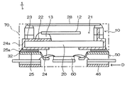
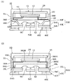
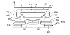
図1に、第1実施形態に係る圧電発振器を分解した状態の斜視図を示す。また図2に、図1のA−A線における側面断面図を示す。なお、図2では樹脂パッケージ70を取り除いた状態を示している。すなわち、図2における積層リードフレーム50の部分の断面は、実際には切断されていない位置の端子部分を付しているが、これは理解の便宜のために付したもので、切断面を示すものではなく、各端子部分等の上下方向(垂直方向)の位置を示すものである。第1実施形態に係る圧電発振器1は、2枚のリードフレーム30、40で構成される積層リードフレーム50につき、圧電振動子10との接続用リード32を上側リードフレーム30に形成し、その接続用リード32を上側に立ち上げて接続端子36を形成するとともに、実装基板への実装用リード42を下側リードフレーム40に形成し、その実装用リード42を下側に立ち上げて実装端子46を形成し、発振回路を形成したIC60を積層リードフレーム50に実装し、パッケージ20の内部に圧電振動片12を封止した圧電振動子10を積層リードフレーム50に実装し、前記実装端子46の主面を露出させつつ、積層リードフレーム50および圧電振動子10を樹脂パッケージ70(図2参照)の内部に封止して形成したものである。なおICは、抵抗やコンデンサ等の電子部品であってもよい。
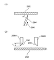
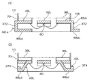
次に、圧電発振器の周波数調整を行なう。図6に、周波数調整工程の説明図を示す。なお図6は、図1のA−A線に相当する部分における側面断面図である。図6(1)に示すように、樹脂パッケージ70の外部に露出している調整端子54に下側からプローブ80を接触させ、IC60への書き込みを行なうことによって圧電発振器1の周波数調整を行なう。なお、プローブ80は、上側から接触させてもよい。なお、周波数調整後の調整端子54は、樹脂パッケージ70の表面付近で切り落とす。また、プローブ80により調整端子54を折り曲げつつ圧電発振器1の周波数調整を行ない、周波数調整後に調整端子54を切り落とすことなくそのまま製品化してもよい。図6(2)は、樹脂パッケージの変形例である。この変形例では、調整端子55の上方に樹脂パッケージ72を拡張成型している。この圧電発振器1の周波数調整も上記と同様に行なうが、周波数調整後に調整端子55を切り落とすことなく、そのまま製品化する。
以上に詳述した第1実施形態にかかる圧電発振器により、平面サイズを小さくすることができる。
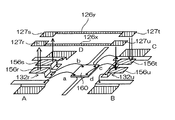
図8に、配線状態の説明図を示す。第2実施形態に係る圧電発振器は、IC160の端子bと実装端子Bとを接続するため、一対の配線用リード132r、132uを上側リードフレーム130に形成し、各配線用リード132r、132uを上側に立ち上げて一対の配線端子156r、156uを形成し、IC端子bに配線用リード132rを接続するとともに、実装端子Bに配線用リード132uを接続し、一対の配線端子156r、156uにそれぞれ接続される一対の電極パッド127r、127uと、一対の電極パッド127r、127uを相互に接続する配線パターン126xとを、圧電振動子に形成したものである。なお、第1実施形態と同様の構成となる部分については、その説明を省略する。
Claims (19)
- 圧電振動片と、該圧電振動片を封止したパッケージと、該パッケージの裏面に形成され、前記圧電振動片と電気的に接続された外部電極と、を有する圧電振動子と、
発振回路が形成されたICと、
上側リードフレームと下側リードフレームとで構成され、前記ICが実装された積層リードフレームと、を有し、
前記上側リードフレームは、端部に位置する第1のパッドと、該第1のパッドより外側に位置する第1の傾斜部と、該第1の傾斜部より外側に位置する接続端子と、を備え、
前記接続端子の主面に前記圧電振動子の前記外部電極が接続されて、前記積層リードフレームに前記圧電振動子が実装され、
前記第1のパッドから前記傾斜部を上側に立ち上げて、前記上側リードフレームから離して平行に前記接続端子を配置し、
前記第1のパッドを前記ICと接続し、
前記下側リードフレームは、端部に位置する第2のパッドと、該第2のパッドより外側に位置する第2の傾斜部と、該第2の傾斜部より外側に位置する実装端子と、を備え、
前記第2のパッドから前記傾斜部を下側に立ち上げて、前記下側リードフレームから離して平行に前記実装端子を配置し、
前記第2のパッドを前記ICに接続し、
前記実装端子の主面を外部に露出させつつ、前記積層リードフレームおよび前記圧電振動子を樹脂パッケージの内部に封止して形成したことを特徴とする圧電発振器。 - 圧電振動片と、該圧電振動片を封止したパッケージと、該パッケージの裏面に形成され、前記圧電振動片と電気的に接続された外部電極と、を有する圧電振動子と、
発振回路が形成されたICと、
上側リードフレームと下側リードフレームとで構成され、前記ICが実装された積層リードフレームと、を有し、
前記上側リードフレームは、端部に位置する第1のパッドと、該第1のパッドより外側に位置する第1の傾斜部と、該第1の傾斜部より外側に位置する接続端子と、を備え、
前記接続端子の主面に前記圧電振動子の前記外部電極が接続されて、前記積層リードフレームに前記圧電振動子が実装され、
前記第1のパッドから前記傾斜部を上側に立ち上げて、前記上側リードフレームから離して平行に前記接続端子を配置し、
前記第1のパッドを前記ICと接続し、
前記下側リードフレームは、端部に位置する第2のパッドと、該第2のパッドより外側に位置する実装端子を備え、
前記第2のパッドと前記実装端子を互いに同一平面内に配置し、
前記第2のパッドを前記ICに接続し、
前記実装端子の主面を外部に露出させつつ、前記積層リードフレームおよび前記圧電振動子を樹脂パッケージの内部に封止して形成したことを特徴とする圧電発振器。 - 請求項1または2に記載の圧電発振器において、
前記上側リードフレームの前記第1のパッドと前記ICとは、ワイヤによって接続されており、
前記第1の傾斜部は、ボンディングされた前記ワイヤの最大高さよりも大きく立ち上げて形成してあることを特徴とする圧電発振器。 - 圧電振動片と、該圧電振動片を封止したパッケージと、該パッケージの裏面に形成され、前記圧電振動片と電気的に接続された外部電極と、を有する圧電振動子と、
発振回路が形成されたICと、
上側リードフレームと下側リードフレームとで構成され、前記ICが実装された積層リードフレームと、を有し、
前記上側リードフレームは、端部に位置する第1のパッドと、該第1のパッドより外側に位置する接続端子を備え、
前記接続端子の主面に前記圧電振動子の前記外部電極が接続されて、前記積層リードフレームに前記圧電振動子が実装され、
前記第1のパッドと前記接続端子を互いに同一平面内に配置し、
前記第1のパッドを前記ICと接続し、
前記下側リードフレームは、端部に位置する第2のパッドと、該第2のパッドより外側に位置する第2の傾斜部と、該第2の傾斜部より外側に位置する実装端子と、を備え、
前記第2のパッドから前記傾斜部を下側に立ち上げて、前記下側リードフレームから離して平行に前記実装端子を配置し、
前記第2のパッドを前記ICに接続し、
前記実装端子の主面を外部に露出させつつ、前記積層リードフレームおよび前記圧電振動子を樹脂パッケージの内部に封止して形成したことを特徴とする圧電発振器。 - 請求項4に記載の圧電発振器において、
前記下側リードフレームの前記第2のパッドと前記ICとは、ワイヤによって接続されており、
前記第2の傾斜部は、ボンディングされた前記ワイヤの最大高さよりも大きく立ち上げて形成してあることを特徴とする圧電発振器。 - 請求項1ないし5のいずれかに記載の圧電発振器において、
前記積層リードフレームに、前記ICの特性検査、特性調整および/または前記圧電振動子と前記接続端子との導通確認をするための調整端子を形成し、
前記調整端子を外部に露出させつつ、前記積層リードフレームおよび前記圧電振動子を樹脂パッケージの内部に封止して形成したことを特徴とする圧電発振器。 - 請求項1ないし6のいずれかに記載の圧電発振器において、
前記実装端子の主面に加えて、前記実装端子の側面を外部に露出させつつ、前記積層リードフレームおよび前記圧電振動子を樹脂パッケージの内部に封止して形成したことを特徴とする圧電発振器。 - 請求項1ないし7のいずれかに記載の圧電発振器において、
前記実装端子は、端部が前記樹脂パッケージの側面から突出していることを特徴とする圧電発振器。 - 請求項1ないし8のいずれかに記載の圧電発振器において、
前記下側リードフレームは、前記樹脂パッケージの樹脂を入り込ませる切り欠きが形成されていることを特徴とする圧電発振器。 - 請求項1ないし9のいずれかに記載の圧電発振器において、
前記上側リードフレームは、前記樹脂パッケージの樹脂を入り込ませる切り欠きが形成されていることを特徴とする圧電発振器。 - 請求項1ないし10のいずれかに記載の圧電発振器において、
前記ICは、前記積層リードフレームのいずれか一方に実装したことを特徴とする圧電発振器。 - 請求項1ないし11のいずれかに記載の圧電発振器において、
前記圧電振動子の高さ方向に対する係止部を前記パッケージの側面に形成した上で、前記積層リードフレームおよび前記圧電振動子を樹脂パッケージの内部に封止して形成したことを特徴とする圧電発振器。 - 請求項1ないし12のいずれかに記載の圧電発振器において、
前記圧電振動子のリッドの上面を外部に露出させつつ、前記積層リードフレームおよび前記圧電振動子を樹脂パッケージの内部に封止して形成したことを特徴とする圧電発振器。 - 請求項1ないし12のいずれかに記載の圧電発振器において、
前記圧電振動子のリッドを前記樹脂パッケージの内部に封止して形成したことを特徴とする圧電発振器。 - 2枚のリードフレームを上下に重ね合わせて構成される積層リードフレームにつき、上側リードフレームは、端部に位置する第1のパッドと、該第1のパッドより外側に位置する第1の傾斜部と、該第1の傾斜部より外側に位置する接続端子と、を形成し、前記接続端子の主面に圧電振動子の外部電極が接続されて、前記積層リードフレームに前記圧電振動子が実装され、前記第1のパッドから前記傾斜部を上側に立ち上げて、前記上側リードフレームから離して平行に前記接続端子を配置するとともに、前記下側リードフレームは、端部に位置する第2のパッドと、該第2のパッドより外側に位置する第2の傾斜部と、該第2の傾斜部より外側に位置する実装端子と、を形成し、前記第2のパッドから前記傾斜部を下側に立ち上げて、前記下側リードフレームから離して平行に前記実装端子を配置し、前記各リードフレームを積層して前記積層リードフレームを形成する工程と、
発振回路を形成したICを、前記積層リードフレームに実装する工程と、
パッケージの内部に圧電振動片を封止した前記圧電振動子を、前記積層リードフレームに実装する工程と、
前記実装端子の主面を外部に露出させつつ、前記積層リードフレームおよび前記圧電振動子を樹脂パッケージの内部に封止する工程と、
を有することを特徴とする圧電発振器の製造方法。 - 2枚のリードフレームを上下に重ね合わせて構成される積層リードフレームにつき、上側リードフレームは、端部に位置する第1のパッドと、該第1のパッドより外側に位置する第1の傾斜部と、該第1の傾斜部より外側に位置する接続端子と、を形成し、前記接続端子の主面に圧電振動子の外部電極が接続されて、前記積層リードフレームに前記圧電振動子が実装され、前記第1のパッドから前記傾斜部を上側に立ち上げて、前記上側リードフレームから離して平行に前記接続端子を配置するとともに、前記下側リードフレームは、端部に位置する第2のパッドと、該第2のパッドより外側に位置する実装端子を形成し、前記第2のパッドと前記実装端子を互いに同一平面内に配置し、前記各リードフレームを積層して前記積層リードフレームを形成する工程と、
発振回路を形成したICを、前記積層リードフレームに実装する工程と、
パッケージの内部に圧電振動片を封止した前記圧電振動子を、前記積層リードフレームに実装する工程と、
前記実装端子の主面を外部に露出させつつ、前記積層リードフレームおよび前記圧電振動子を樹脂パッケージの内部に封止する工程と、
を有することを特徴とする圧電発振器の製造方法。 - 請求項15または16に記載の圧電発振器の製造方法において、
前記実装端子の主面に付着した樹脂を除去する工程を有することを特徴とする圧電発振器の製造方法。 - 請求項15ないし17のいずれかに記載の圧電発振器の製造方法において、
前記樹脂パッケージの内部に封止する工程は、前記実装端子の主面を金型面に押圧して行ない、
その後の前記樹脂パッケージを前記リードフレームの枠部から切り離す工程において、前記実装端子の不要部を切断する、
ことを特徴とする圧電発振器の製造方法。 - 請求項1ないし14のいずれかに記載の圧電発振器を有することを特徴とする電子機器。
Priority Applications (5)
| Application Number | Priority Date | Filing Date | Title |
|---|---|---|---|
| JP2003334616A JP3918794B2 (ja) | 2002-12-10 | 2003-09-26 | 圧電発振器およびその製造方法並びに電子機器 |
| US10/729,010 US7123107B2 (en) | 2002-12-10 | 2003-12-08 | Piezoelectric oscillator, manufacturing method thereof, and electronic device |
| DE60319662T DE60319662T2 (de) | 2002-12-10 | 2003-12-10 | Piezoelektrischer Oszillator, dessen Herstellungsverfahren und elektronisches Bauteil |
| EP03028267A EP1429459B1 (en) | 2002-12-10 | 2003-12-10 | Piezoelectric oscillator, manufacturing method thereof, and electronic device |
| US11/471,710 US7408291B2 (en) | 2002-12-10 | 2006-06-21 | Piezoelectric oscillator, manufacturing method thereof, and electronic device |
Applications Claiming Priority (4)
| Application Number | Priority Date | Filing Date | Title |
|---|---|---|---|
| JP2002358392 | 2002-12-10 | ||
| JP2003106598 | 2003-04-10 | ||
| JP2003171195 | 2003-06-16 | ||
| JP2003334616A JP3918794B2 (ja) | 2002-12-10 | 2003-09-26 | 圧電発振器およびその製造方法並びに電子機器 |
Publications (3)
| Publication Number | Publication Date |
|---|---|
| JP2005033755A JP2005033755A (ja) | 2005-02-03 |
| JP2005033755A5 JP2005033755A5 (ja) | 2006-11-09 |
| JP3918794B2 true JP3918794B2 (ja) | 2007-05-23 |
Family
ID=32329972
Family Applications (1)
| Application Number | Title | Priority Date | Filing Date |
|---|---|---|---|
| JP2003334616A Expired - Lifetime JP3918794B2 (ja) | 2002-12-10 | 2003-09-26 | 圧電発振器およびその製造方法並びに電子機器 |
Country Status (4)
| Country | Link |
|---|---|
| US (2) | US7123107B2 (ja) |
| EP (1) | EP1429459B1 (ja) |
| JP (1) | JP3918794B2 (ja) |
| DE (1) | DE60319662T2 (ja) |
Families Citing this family (48)
| Publication number | Priority date | Publication date | Assignee | Title |
|---|---|---|---|---|
| JP3918794B2 (ja) * | 2002-12-10 | 2007-05-23 | セイコーエプソン株式会社 | 圧電発振器およびその製造方法並びに電子機器 |
| JP4312616B2 (ja) * | 2004-01-26 | 2009-08-12 | Necエレクトロニクス株式会社 | 半導体装置 |
| JP4238779B2 (ja) * | 2004-05-28 | 2009-03-18 | セイコーエプソン株式会社 | 圧電発振器および電子機器 |
| JP2006165759A (ja) * | 2004-12-03 | 2006-06-22 | Nippon Dempa Kogyo Co Ltd | 温度補償水晶発振器及びその製造方法 |
| JP4311376B2 (ja) * | 2005-06-08 | 2009-08-12 | セイコーエプソン株式会社 | 半導体装置、半導体装置の製造方法、電子部品、回路基板及び電子機器 |
| TWM288015U (en) * | 2005-08-26 | 2006-02-21 | Inventec Appliances Corp | Mobile phone antenna |
| JP2007074066A (ja) * | 2005-09-05 | 2007-03-22 | Seiko Epson Corp | 圧電デバイス |
| US20070126316A1 (en) * | 2005-12-01 | 2007-06-07 | Epson Toyocom Corporation | Electronic device |
| JP4240053B2 (ja) * | 2006-04-24 | 2009-03-18 | エプソントヨコム株式会社 | 圧電発振器とその製造方法 |
| JP4973290B2 (ja) * | 2006-06-12 | 2012-07-11 | セイコーエプソン株式会社 | プローブ接触用電極、パッケージ及び電子デバイス |
| JP4952083B2 (ja) * | 2006-06-21 | 2012-06-13 | セイコーエプソン株式会社 | 圧電発振器 |
| WO2008038767A1 (fr) * | 2006-09-30 | 2008-04-03 | Citizen Finetech Miyota Co., Ltd. | dispositif piézoélectrique |
| US7681290B2 (en) * | 2006-10-20 | 2010-03-23 | The Boeing Company | Piezoelectric bimorph beam manufacturing method |
| JP2008109429A (ja) * | 2006-10-26 | 2008-05-08 | Epson Toyocom Corp | 圧電デバイス |
| JP5101093B2 (ja) * | 2006-11-30 | 2012-12-19 | 京セラクリスタルデバイス株式会社 | 圧電発振器及びその製造方法 |
| JP4976263B2 (ja) * | 2006-12-28 | 2012-07-18 | 日本電波工業株式会社 | 表面実装用の水晶発振器 |
| US7731219B2 (en) * | 2007-04-23 | 2010-06-08 | Cequent Trailer Products, Inc. | Trailer tongue pivot hinge |
| JP5059478B2 (ja) * | 2007-04-26 | 2012-10-24 | 日本電波工業株式会社 | 表面実装用の圧電発振器及び圧電振動子 |
| CN101790787B (zh) * | 2007-08-23 | 2012-07-18 | 株式会社大真空 | 电子部件用封装、电子部件用封装的基底、以及电子部件用封装与电路基板的接合结构 |
| US7876168B2 (en) * | 2007-12-14 | 2011-01-25 | Epson Toyocom Corporation | Piezoelectric oscillator and method for manufacturing the same |
| JP5262530B2 (ja) * | 2008-09-30 | 2013-08-14 | セイコーエプソン株式会社 | 電子デバイス及び電子デバイスの製造方法 |
| DE112009002380T5 (de) * | 2008-10-03 | 2011-09-29 | Cts Corp. | Ofen-stabilisierte Quarz-Oszillator-Anordnung |
| JP2010190706A (ja) * | 2009-02-18 | 2010-09-02 | Panasonic Corp | 慣性力センサ |
| TWI527280B (zh) * | 2009-04-03 | 2016-03-21 | Daishinku Corp | A manufacturing method of a package body assembly, a package body assembly, a package member, and a method of manufacturing a piezoelectric vibration element using a package member |
| JP5275155B2 (ja) * | 2009-06-26 | 2013-08-28 | セイコーインスツル株式会社 | 電子デバイスの製造方法 |
| JP5362643B2 (ja) * | 2009-06-30 | 2013-12-11 | 日本電波工業株式会社 | 積層型の水晶振動子 |
| US20110068880A1 (en) * | 2009-09-18 | 2011-03-24 | Gavin Ho | Micromechanical network |
| CN102714187B (zh) * | 2010-03-24 | 2016-01-27 | 株式会社大真空 | 电子部件用封装的基座和电子部件用封装 |
| CN102456806A (zh) * | 2010-10-26 | 2012-05-16 | 展晶科技(深圳)有限公司 | 发光二极管封装结构 |
| TWI420810B (zh) | 2010-12-17 | 2013-12-21 | Ind Tech Res Inst | 石英振盪器及其製造方法 |
| JP2012222537A (ja) * | 2011-04-07 | 2012-11-12 | Seiko Epson Corp | パッケージ、振動子、発振器及び電子機器 |
| JP5204271B2 (ja) * | 2011-06-16 | 2013-06-05 | 株式会社東芝 | 内視鏡装置および基板 |
| US9230890B2 (en) * | 2012-04-27 | 2016-01-05 | Lapis Semiconductor Co., Ltd. | Semiconductor device and measurement device |
| USD759022S1 (en) * | 2013-03-13 | 2016-06-14 | Nagrastar Llc | Smart card interface |
| USD758372S1 (en) * | 2013-03-13 | 2016-06-07 | Nagrastar Llc | Smart card interface |
| USD729808S1 (en) * | 2013-03-13 | 2015-05-19 | Nagrastar Llc | Smart card interface |
| JP6127651B2 (ja) * | 2013-03-29 | 2017-05-17 | セイコーエプソン株式会社 | 電子デバイス、電子機器、移動体および電子デバイスの製造方法 |
| JP2014236466A (ja) * | 2013-06-05 | 2014-12-15 | 日本電波工業株式会社 | デュアルモード水晶発振器 |
| US10103709B2 (en) * | 2013-11-05 | 2018-10-16 | Kyocera Corporation | Crystal unit |
| US20150188025A1 (en) * | 2013-12-30 | 2015-07-02 | Nihon Dempa Kogyo Co., Ltd. | Container for electronic component and electronic component |
| JP6644457B2 (ja) * | 2014-03-26 | 2020-02-12 | Tdk株式会社 | 圧電デバイス |
| US9165869B1 (en) * | 2014-07-11 | 2015-10-20 | Freescale Semiconductor, Inc. | Semiconductor device with twisted leads |
| JP6373115B2 (ja) * | 2014-08-05 | 2018-08-15 | 日本特殊陶業株式会社 | 配線基板 |
| USD760230S1 (en) * | 2014-09-16 | 2016-06-28 | Daishinku Corporation | Piezoelectric vibration device |
| USD780763S1 (en) * | 2015-03-20 | 2017-03-07 | Nagrastar Llc | Smart card interface |
| USD864968S1 (en) * | 2015-04-30 | 2019-10-29 | Echostar Technologies L.L.C. | Smart card interface |
| JP7143951B2 (ja) * | 2019-07-17 | 2022-09-29 | 株式会社村田製作所 | 半導体モジュール |
| CN117546406A (zh) * | 2021-09-30 | 2024-02-09 | 株式会社大真空 | 压电振动器件 |
Family Cites Families (41)
| Publication number | Priority date | Publication date | Assignee | Title |
|---|---|---|---|---|
| JPS5587544A (en) | 1978-12-26 | 1980-07-02 | Toyo Aluminium Kk | Preparation of metalized laminate |
| DE2918952C2 (de) * | 1979-05-10 | 1982-10-28 | Siemens AG, 1000 Berlin und 8000 München | Elektrische Baugruppe |
| JPS63244905A (ja) | 1987-03-30 | 1988-10-12 | Matsushima Kogyo Co Ltd | 圧電発振器 |
| JPS63305604A (ja) | 1987-06-08 | 1988-12-13 | Matsushima Kogyo Co Ltd | 圧電発振器 |
| JPH0644537B2 (ja) | 1987-09-25 | 1994-06-08 | 株式会社東芝 | 箔巻変圧器 |
| GB2211021A (en) | 1987-10-10 | 1989-06-21 | Stc Plc | Crystal oscillator |
| JPH0516724Y2 (ja) | 1987-11-20 | 1993-05-06 | ||
| JPH0641196B2 (ja) | 1987-12-01 | 1994-06-01 | 株式会社巴川製紙所 | 印刷用シート |
| JPH01189151A (ja) | 1988-01-25 | 1989-07-28 | Oki Electric Ind Co Ltd | 面実装型半導体装置の外部リード |
| JPH01145140U (ja) | 1988-03-28 | 1989-10-05 | ||
| JP2728263B2 (ja) | 1988-06-15 | 1998-03-18 | 株式会社トプコン | 眼鏡用画像処理装置 |
| JPH024312U (ja) | 1988-06-20 | 1990-01-11 | ||
| EP0473796A4 (en) * | 1990-03-15 | 1994-05-25 | Fujitsu Ltd | Semiconductor device having a plurality of chips |
| JPH0429224A (ja) | 1990-05-25 | 1992-01-31 | Ricoh Co Ltd | マルチ発光オートストロボ装置 |
| JPH04116416A (ja) | 1990-09-06 | 1992-04-16 | Nissin Electric Co Ltd | 光強度変調センサ |
| JPH04116416U (ja) | 1991-03-28 | 1992-10-19 | 京セラ株式会社 | 水晶発振器 |
| JPH04334202A (ja) | 1991-05-10 | 1992-11-20 | Seiko Epson Corp | 圧電発振器 |
| JPH0547990A (ja) | 1991-08-07 | 1993-02-26 | Ricoh Co Ltd | 多層リードフレームと半導体装置実装体 |
| US5479051A (en) * | 1992-10-09 | 1995-12-26 | Fujitsu Limited | Semiconductor device having a plurality of semiconductor chips |
| JPH0730051A (ja) * | 1993-07-09 | 1995-01-31 | Fujitsu Ltd | 半導体装置 |
| JPH07162236A (ja) | 1993-12-03 | 1995-06-23 | Seiko Epson Corp | 圧電発振器及びその製造方法 |
| WO1996001524A1 (en) | 1994-07-04 | 1996-01-18 | Seiko Epson Corporation | Piezoelectric oscillator |
| JP3230742B2 (ja) | 1994-07-04 | 2001-11-19 | セイコーエプソン株式会社 | 圧電発振器 |
| JP2621828B2 (ja) | 1995-06-26 | 1997-06-18 | セイコーエプソン株式会社 | 圧電発振器 |
| TW372370B (en) | 1995-08-25 | 1999-10-21 | Mitsui Petroleum Chemicals Ind | Supporting structure of piezoelectric vibrator parts and piezoelectric vibrator, and the method of packaging of piezoelectric vibrator |
| JPH09260740A (ja) | 1996-03-19 | 1997-10-03 | Mitsui Petrochem Ind Ltd | 圧電トランスおよびその製造方法 |
| JPH09219491A (ja) | 1996-02-08 | 1997-08-19 | Toshiba Corp | リードフレーム及び半導体装置 |
| KR100214561B1 (ko) | 1997-03-14 | 1999-08-02 | 구본준 | 버틈 리드 패키지 |
| JPH11284441A (ja) | 1998-03-30 | 1999-10-15 | Nippon Dempa Kogyo Co Ltd | 温度補償水晶発振器の製造方法 |
| JP2000031367A (ja) | 1998-07-14 | 2000-01-28 | Hitachi Ltd | 半導体装置及びその製造方法 |
| JP2000150720A (ja) | 1998-11-05 | 2000-05-30 | Fuji Electric Co Ltd | 樹脂封止型半導体デバイス |
| JP2000150768A (ja) | 1998-11-13 | 2000-05-30 | Dainippon Printing Co Ltd | リードフレーム部材とその製造方法および樹脂封止型半導体装置 |
| JP2000323641A (ja) | 1999-05-07 | 2000-11-24 | Matsushita Electronics Industry Corp | リードフレームおよびその製造方法 |
| JP2001332932A (ja) | 2000-05-22 | 2001-11-30 | Daishinku Corp | 圧電発振器 |
| JP2002176318A (ja) | 2000-09-27 | 2002-06-21 | Citizen Watch Co Ltd | 圧電発振器及びその実装構造 |
| JP3436249B2 (ja) | 2000-11-21 | 2003-08-11 | 株式会社大真空 | 圧電振動デバイス用パッケージおよび圧電発振器 |
| JP2002330027A (ja) | 2001-04-27 | 2002-11-15 | Nippon Dempa Kogyo Co Ltd | 表面実装用の温度補償水晶発振器 |
| JP4222147B2 (ja) * | 2002-10-23 | 2009-02-12 | セイコーエプソン株式会社 | 圧電発振器及び圧電発振器を利用した携帯電話装置および圧電発振器を利用した電子機器 |
| JP3918794B2 (ja) * | 2002-12-10 | 2007-05-23 | セイコーエプソン株式会社 | 圧電発振器およびその製造方法並びに電子機器 |
| JP4222020B2 (ja) * | 2002-12-17 | 2009-02-12 | セイコーエプソン株式会社 | 圧電発振器 |
| JP3841304B2 (ja) * | 2004-02-17 | 2006-11-01 | セイコーエプソン株式会社 | 圧電発振器、及びその製造方法 |
-
2003
- 2003-09-26 JP JP2003334616A patent/JP3918794B2/ja not_active Expired - Lifetime
- 2003-12-08 US US10/729,010 patent/US7123107B2/en not_active Expired - Lifetime
- 2003-12-10 EP EP03028267A patent/EP1429459B1/en not_active Expired - Lifetime
- 2003-12-10 DE DE60319662T patent/DE60319662T2/de not_active Expired - Lifetime
-
2006
- 2006-06-21 US US11/471,710 patent/US7408291B2/en not_active Expired - Lifetime
Also Published As
| Publication number | Publication date |
|---|---|
| JP2005033755A (ja) | 2005-02-03 |
| EP1429459A2 (en) | 2004-06-16 |
| EP1429459A3 (en) | 2005-09-21 |
| US20040135645A1 (en) | 2004-07-15 |
| US7408291B2 (en) | 2008-08-05 |
| US7123107B2 (en) | 2006-10-17 |
| DE60319662D1 (de) | 2008-04-24 |
| US20060238080A1 (en) | 2006-10-26 |
| DE60319662T2 (de) | 2009-04-02 |
| EP1429459B1 (en) | 2008-03-12 |
Similar Documents
| Publication | Publication Date | Title |
|---|---|---|
| JP3918794B2 (ja) | 圧電発振器およびその製造方法並びに電子機器 | |
| TWI314812B (ja) | ||
| US8499443B2 (en) | Method of manufacturing a piezoelectric vibrator | |
| JP4990717B2 (ja) | ケースの製造方法、圧電振動子、発振器、電子機器、及び電波時計 | |
| JP4232190B2 (ja) | 圧電発振器、及びその製造方法、並びに圧電発振器を利用した携帯電話装置、電子機器 | |
| KR100661690B1 (ko) | 압전 발진기 및 그 제조 방법과, 휴대 전화 장치 및 전자기기 | |
| JP5252992B2 (ja) | 水晶発振器用パッケージおよび水晶発振器 | |
| JP2007043462A (ja) | 圧電発振器および電子機器 | |
| JP4167557B2 (ja) | 圧電発振器の製造方法 | |
| JP2001177347A (ja) | 水晶発振器 | |
| JP5024317B2 (ja) | 電子部品および電子部品の製造方法 | |
| JP2003179432A (ja) | 圧電発振器の製造方法、圧電発振器および集積回路素子パッケージ | |
| JP4511335B2 (ja) | 多数個取り配線基板および電子装置 | |
| JP2008011029A (ja) | 圧電発振器 | |
| JP4952083B2 (ja) | 圧電発振器 | |
| JP2005192179A (ja) | 圧電発振器、及びこれを利用した携帯電話装置、電子機器 | |
| JP2001144572A (ja) | セラミック容器及びこれを用いた水晶振動子 | |
| KR100501190B1 (ko) | 슬림형 수정발진기 | |
| JP2002084138A (ja) | チップ型水晶発振器 | |
| JP2001102868A (ja) | 表面実装水晶発振器及びその製造方法 | |
| JP2008005189A (ja) | 圧電発振器 | |
| JP2008227654A (ja) | 圧電デバイスの製造方法、圧電デバイスおよび電子機器 |
Legal Events
| Date | Code | Title | Description |
|---|---|---|---|
| A521 | Request for written amendment filed |
Free format text: JAPANESE INTERMEDIATE CODE: A523 Effective date: 20060926 |
|
| A621 | Written request for application examination |
Free format text: JAPANESE INTERMEDIATE CODE: A621 Effective date: 20060926 |
|
| A871 | Explanation of circumstances concerning accelerated examination |
Free format text: JAPANESE INTERMEDIATE CODE: A871 Effective date: 20060926 |
|
| A975 | Report on accelerated examination |
Free format text: JAPANESE INTERMEDIATE CODE: A971005 Effective date: 20061011 |
|
| A131 | Notification of reasons for refusal |
Free format text: JAPANESE INTERMEDIATE CODE: A131 Effective date: 20061025 |
|
| A521 | Request for written amendment filed |
Free format text: JAPANESE INTERMEDIATE CODE: A523 Effective date: 20061225 |
|
| TRDD | Decision of grant or rejection written | ||
| A01 | Written decision to grant a patent or to grant a registration (utility model) |
Free format text: JAPANESE INTERMEDIATE CODE: A01 Effective date: 20070123 |
|
| A61 | First payment of annual fees (during grant procedure) |
Free format text: JAPANESE INTERMEDIATE CODE: A61 Effective date: 20070205 |
|
| R150 | Certificate of patent or registration of utility model |
Ref document number: 3918794 Country of ref document: JP Free format text: JAPANESE INTERMEDIATE CODE: R150 Free format text: JAPANESE INTERMEDIATE CODE: R150 |
|
| FPAY | Renewal fee payment (event date is renewal date of database) |
Free format text: PAYMENT UNTIL: 20110223 Year of fee payment: 4 |
|
| FPAY | Renewal fee payment (event date is renewal date of database) |
Free format text: PAYMENT UNTIL: 20110223 Year of fee payment: 4 |
|
| FPAY | Renewal fee payment (event date is renewal date of database) |
Free format text: PAYMENT UNTIL: 20120223 Year of fee payment: 5 |
|
| FPAY | Renewal fee payment (event date is renewal date of database) |
Free format text: PAYMENT UNTIL: 20130223 Year of fee payment: 6 |
|
| FPAY | Renewal fee payment (event date is renewal date of database) |
Free format text: PAYMENT UNTIL: 20130223 Year of fee payment: 6 |
|
| S111 | Request for change of ownership or part of ownership |
Free format text: JAPANESE INTERMEDIATE CODE: R313113 |
|
| R350 | Written notification of registration of transfer |
Free format text: JAPANESE INTERMEDIATE CODE: R350 |
|
| R250 | Receipt of annual fees |
Free format text: JAPANESE INTERMEDIATE CODE: R250 |
|
| R250 | Receipt of annual fees |
Free format text: JAPANESE INTERMEDIATE CODE: R250 |
|
| R250 | Receipt of annual fees |
Free format text: JAPANESE INTERMEDIATE CODE: R250 |
|
| R250 | Receipt of annual fees |
Free format text: JAPANESE INTERMEDIATE CODE: R250 |
|
| R250 | Receipt of annual fees |
Free format text: JAPANESE INTERMEDIATE CODE: R250 |
|
| R250 | Receipt of annual fees |
Free format text: JAPANESE INTERMEDIATE CODE: R250 |
|
| R250 | Receipt of annual fees |
Free format text: JAPANESE INTERMEDIATE CODE: R250 |
|
| R250 | Receipt of annual fees |
Free format text: JAPANESE INTERMEDIATE CODE: R250 |
|
| R250 | Receipt of annual fees |
Free format text: JAPANESE INTERMEDIATE CODE: R250 |
|
| R250 | Receipt of annual fees |
Free format text: JAPANESE INTERMEDIATE CODE: R250 |
|
| EXPY | Cancellation because of completion of term |