EP3654822B1 - Dynamically rigidizing overtube - Google Patents
Dynamically rigidizing overtube Download PDFInfo
- Publication number
- EP3654822B1 EP3654822B1 EP18835355.1A EP18835355A EP3654822B1 EP 3654822 B1 EP3654822 B1 EP 3654822B1 EP 18835355 A EP18835355 A EP 18835355A EP 3654822 B1 EP3654822 B1 EP 3654822B1
- Authority
- EP
- European Patent Office
- Prior art keywords
- engagers
- overtube
- male
- female
- rigidizing
- Prior art date
- Legal status (The legal status is an assumption and is not a legal conclusion. Google has not performed a legal analysis and makes no representation as to the accuracy of the status listed.)
- Active
Links
Images


Classifications
-
- A—HUMAN NECESSITIES
- A61—MEDICAL OR VETERINARY SCIENCE; HYGIENE
- A61B—DIAGNOSIS; SURGERY; IDENTIFICATION
- A61B1/00—Instruments for performing medical examinations of the interior of cavities or tubes of the body by visual or photographical inspection, e.g. endoscopes; Illuminating arrangements therefor
- A61B1/00064—Constructional details of the endoscope body
- A61B1/00071—Insertion part of the endoscope body
- A61B1/00078—Insertion part of the endoscope body with stiffening means
-
- A—HUMAN NECESSITIES
- A61—MEDICAL OR VETERINARY SCIENCE; HYGIENE
- A61B—DIAGNOSIS; SURGERY; IDENTIFICATION
- A61B1/00—Instruments for performing medical examinations of the interior of cavities or tubes of the body by visual or photographical inspection, e.g. endoscopes; Illuminating arrangements therefor
- A61B1/00131—Accessories for endoscopes
- A61B1/00135—Oversleeves mounted on the endoscope prior to insertion
-
- A—HUMAN NECESSITIES
- A61—MEDICAL OR VETERINARY SCIENCE; HYGIENE
- A61B—DIAGNOSIS; SURGERY; IDENTIFICATION
- A61B1/00—Instruments for performing medical examinations of the interior of cavities or tubes of the body by visual or photographical inspection, e.g. endoscopes; Illuminating arrangements therefor
- A61B1/00002—Operational features of endoscopes
- A61B1/00039—Operational features of endoscopes provided with input arrangements for the user
- A61B1/00042—Operational features of endoscopes provided with input arrangements for the user for mechanical operation
-
- A—HUMAN NECESSITIES
- A61—MEDICAL OR VETERINARY SCIENCE; HYGIENE
- A61B—DIAGNOSIS; SURGERY; IDENTIFICATION
- A61B1/00—Instruments for performing medical examinations of the interior of cavities or tubes of the body by visual or photographical inspection, e.g. endoscopes; Illuminating arrangements therefor
- A61B1/005—Flexible endoscopes
- A61B1/0051—Flexible endoscopes with controlled bending of insertion part
- A61B1/0052—Constructional details of control elements, e.g. handles
-
- A—HUMAN NECESSITIES
- A61—MEDICAL OR VETERINARY SCIENCE; HYGIENE
- A61B—DIAGNOSIS; SURGERY; IDENTIFICATION
- A61B1/00—Instruments for performing medical examinations of the interior of cavities or tubes of the body by visual or photographical inspection, e.g. endoscopes; Illuminating arrangements therefor
- A61B1/005—Flexible endoscopes
- A61B1/0051—Flexible endoscopes with controlled bending of insertion part
- A61B1/0055—Constructional details of insertion parts, e.g. vertebral elements
-
- A—HUMAN NECESSITIES
- A61—MEDICAL OR VETERINARY SCIENCE; HYGIENE
- A61B—DIAGNOSIS; SURGERY; IDENTIFICATION
- A61B1/00—Instruments for performing medical examinations of the interior of cavities or tubes of the body by visual or photographical inspection, e.g. endoscopes; Illuminating arrangements therefor
- A61B1/005—Flexible endoscopes
- A61B1/0051—Flexible endoscopes with controlled bending of insertion part
- A61B1/0057—Constructional details of force transmission elements, e.g. control wires
-
- A—HUMAN NECESSITIES
- A61—MEDICAL OR VETERINARY SCIENCE; HYGIENE
- A61B—DIAGNOSIS; SURGERY; IDENTIFICATION
- A61B1/00—Instruments for performing medical examinations of the interior of cavities or tubes of the body by visual or photographical inspection, e.g. endoscopes; Illuminating arrangements therefor
- A61B1/005—Flexible endoscopes
- A61B1/008—Articulations
-
- A—HUMAN NECESSITIES
- A61—MEDICAL OR VETERINARY SCIENCE; HYGIENE
- A61B—DIAGNOSIS; SURGERY; IDENTIFICATION
- A61B17/00—Surgical instruments, devices or methods
- A61B17/00234—Surgical instruments, devices or methods for minimally invasive surgery
- A61B2017/00292—Surgical instruments, devices or methods for minimally invasive surgery mounted on or guided by flexible, e.g. catheter-like, means
- A61B2017/003—Steerable
- A61B2017/00318—Steering mechanisms
-
- A—HUMAN NECESSITIES
- A61—MEDICAL OR VETERINARY SCIENCE; HYGIENE
- A61B—DIAGNOSIS; SURGERY; IDENTIFICATION
- A61B34/00—Computer-aided surgery; Manipulators or robots specially adapted for use in surgery
- A61B34/30—Surgical robots
- A61B2034/301—Surgical robots for introducing or steering flexible instruments inserted into the body, e.g. catheters or endoscopes
-
- A—HUMAN NECESSITIES
- A61—MEDICAL OR VETERINARY SCIENCE; HYGIENE
- A61M—DEVICES FOR INTRODUCING MEDIA INTO, OR ONTO, THE BODY; DEVICES FOR TRANSDUCING BODY MEDIA OR FOR TAKING MEDIA FROM THE BODY; DEVICES FOR PRODUCING OR ENDING SLEEP OR STUPOR
- A61M25/00—Catheters; Hollow probes
- A61M25/01—Introducing, guiding, advancing, emplacing or holding catheters
- A61M25/0105—Steering means as part of the catheter or advancing means; Markers for positioning
- A61M25/0133—Tip steering devices
- A61M25/0155—Tip steering devices with hydraulic or pneumatic means, e.g. balloons or inflatable compartments
Definitions
- looping is a known clinical challenge for endoscopy. Indeed, one study found that looping occurred in 91 of 100 patients undergoing colonoscopy [ Shah et al, "Magnetic Imaging of Colonoscopy: An Audit of Looping, Accuracy and Ancillary maneuvers.” GastrointestEndosc 2000; 52: 1-8 ]. Looping prolongs the procedure and can cause pain to the patient because it can stretch the vessel wall and the mesentery. Furthermore, looping leads to an increased incidence of perforations.
- US 2015/216589 A1 discloses a system and method for the delivery of a medical device to a treatment location.
- the device includes an elongate body, the elongate body including a plurality of annular segments and a jacket disposed about the plurality of annular segments and defining an interior space, and a vacuum source in fluid communication with the interior space of the jacket.
- a vacuum is applied to the interior space of the jacket, the jacket constricts about the plurality of annular elements, thereby increasing the frictional forces between the plurality of segments and between the plurality of segments and an inner surface of the jacket.
- Described herein are devices that can dynamically transition from a configuration of high flexibility to a configuration of high rigidity to help guide a medical device, such as an endoscope, through tortuous body lumens or within other bodily spaces.
- overtubes that are configured to aid in transporting an endoscope through a curved or looped vessel.
- the overtubes described herein are long, thin, and hollow and can transition quickly from a flexible configuration (i.e., one that is relaxed, limp, floppy) to a rigid configuration (i.e., one that is stiff).
- the overtubes can transition from the flexible configuration to the rigid configuration, for example, by applying a vacuum to the overtube.
- the overtubes described herein provide rigidization for devices, including catheters, sheaths, endoscopes, laparoscopic instruments or robotic surgical equipment.
- the overtubes can function as a separate add-on device or can be integrated into the body of the catheters, sheaths, endoscopes laparoscopic instruments or robotic surgical equipment.
- the stiffness of the overtubes described herein can increase from 2 fold to over 30 fold, for instance 10-fold, or 20-fold, when transitioned from the flexible configuration to the rigid configuration
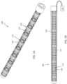
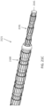
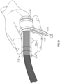
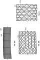
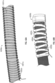
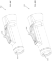
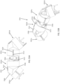
- an overtube 100 can be connected to a vacuum pump 110. Further, the overtube 100 can include an inner tube 101 having a plurality of interconnectable links 103 extending thereover.
- the links 103 can include a series of female engagers 128 and a series of male engagers 114 configured to engage with one another.
- the links 103 can each include a mounting ring 122 from which the engagers 128, 114 extend.
- the mounting ring 122 can be bonded or fixed to the inner tube 101, which can in turn fix the ends of the engagers 128, 114 that are attached to the mounting ring 122 relative to the inner tube.
- the ends of the engagers 128, 114 not bonded to the ring 122 can remain free to move axially relative to one another as the inner tube 101 bends.
- An outer layer 105 can be sealed over the top of the overtube 100.
- the outer layer 105 can provide a sealed area around the links 103.
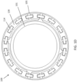
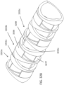
- FIGS. 2A-2C An exemplary embodiment of a link 203 (which can be used as link 103) is shown in FIGS. 2A-2C .
- the link 203 includes a mounting ring 222 having male engagers 214 and female engagers 228 extending therefrom.
- the male engagers 214 can be, for example, narrow and thin extensions from the mounting ring 222.
- the female engagers 228 each include an outer flange 227 and inner flange 229 configured to fit a male engager 214 therebetween.
- each male engager 214 and female engager 228 can be attached to the mounting ring 222 through a pivot mechanism 233, e.g., a narrow piece of material that provides for flexibility of the engagers 214, 228 relative to the ring 222.
- the pivot mechanism 233 can allow for pivoting at angles of up to 30 degrees, such as 5-20 degrees, such as approximately 10 degrees.
- each link 203 can be from a single piece of material, such as a molded polymer.
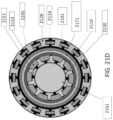
- the links 203a,b can be configured to engage with one another. That is, the male engagers 214 and female engagers 228 can be arranged in an alternating pattern around the circumference of the overtube such that each male engager 214 is held in place by two neighboring female engagers 228. Further, the male engager 214 can move axially within the female engager 228. As the inner tube bends along the longitudinal axis, the pivot mechanisms 233 can provide pivoting of the male and female engagers 214, 228. Simultaneously, the male and female engagers 214, 228 can move axially with respect to one another to follow the bend of the inner tube 201.
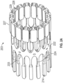
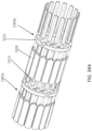
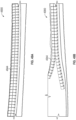
- each engager 428, 414 i.e., the length of each engager that does not engage or mate with neighboring engagers
- the unengaged length of each engager 428, 414 dynamically varies as the inner tube 401 bends (from a neutral set position when the tube is straight to a longer length when the engagers are on the outer axis as the tube is bent and a shorter length when the engagers are on the inner axis as the tube is bent).
- the outer and inner flanges of the female engagers 428 advantageously extend circumferentially over at least a portion of the male engagers 414 so as to prevent the free ends of the male engagers 414 from popping out of the female engagers 428, thereby helping to keep the engagers 414, 428 substantially radially flush with the inner tube 401 (i.e., the engagers 414, 428 stay substantially in-plane as the inner tube 401 bends).
- the pivots can advantageously supply high axial stiffness in both tension and compression, and resist shear loads, while simultaneously offering low bending force.
- the engagers 414, 428 can substantially conform to the bends of the inner tube 401.
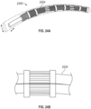
- the outer layer 405 can be sealed over the chain of links 403.
- a vacuum input line 444 can extend from the layer 405.
- the layer 405 can be suctioned down or constricted over the connected links 403, causing the links 403 to radially constrict to become fixed or locked in place relative to one another.
- the overtube 400 can go from a flexible configuration to a rigid configuration when vacuum is pulled (thereby fixing the overtube in the configuration that the overtube was in just prior to application of the vacuum). As it is rigidized, it does so in the shape it was in before vacuum was applied, i.e., it does not straighten, bend, or otherwise substantially modify its shape.
- the links 403 can unlock relative to one another and again move so as to allow bending of the overtube 400. Again, as it is made more flexible through the release of vacuum, it does so in the shape it was in before the vacuum was release., i.e., it does not straighten, bend, or otherwise substantially modify its shape.
- the overtube 400 (and any overtube described herein) can transition from a flexible, less-stiff configuration to a rigid configuration of higher stiffness by increasing friction between the links (e.g., by applying vacuum).
- the space between the layer 405 and inner tube 401 and/or links 403 is filled with a gas in the flexible configuration, and the gas is removed in the rigid configuration.
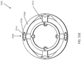
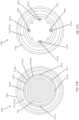
- each link 503 includes a mounting ring 522 having a plurality of sockets 557 extending circumferentially therearound.
- the female engagers 528 and male engagers 514 each include balls 555 on the end thereof configured to fit and pivot within the respective socket 557.
- the mounting ring 522 can include a protective sealing ring 559 thereover to hold each of the balls 555 within the sockets 557.
- the link 503 can be made of a molded polymer.
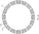
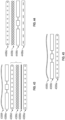
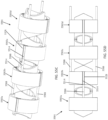
- link 603a includes mounting ring 622 with a plurality of male engagers 614 extending from either end.
- Link 603b includes mounting ring 622 with a plurality of female engagers 628 extending from either end.
- the link 603a (or only link described herein) can include only male engagers 614 while the neighboring link 603b can include female engagers 628 configured to engage therewith.
- the engagers 614, 628 can be made of a metal sheet.
- a wire pivot 633 can connect the engagers 614, 628 to the ring 622.
- This wire pivot 633 advantageously enables high tensile stiffness.
- the length of the wire pivot 633 can be short (for example, .25 mm, .5 mm, 1 mm, 1.5 mm), allowing it to exhibit high compression and tensile stiffness and high resistance to shear loads while also providing the requisite low bending force that enables the overtube to deliver a low baseline bending stiffness / high flexibility.
- Exemplary wire pivots include a 0.008" diameter s.s. cable, 0.012" diameter s.s. wire, 0.025" diameter plastic, or 0.006" nitinol wire.
- FIGS. 9A-9E Another embodiment of a link 903 is shown in FIGS. 9A-9E .
- the link includes a mounting ring 922 with wire pivots 933 extending therefrom.
- Male and female engagers 914, 928, respectively, are molded over the wire pivot 933 while leaving some of the wire pivot 933 exposed near each mounting ring 922.
- LCP liquid crystal polymer
- the engagers 914, 928 can also be made of other plastics of high modulus such as mineral filled grades, PEEK, or ultem. Frictionally enhancing materials can also be used to preferentially lock mating engagers, with frictional coefficients of 0.6, 0.8, 1, or greater.
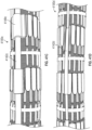
- the link 3303 includes a mounting ring 3322 from which a series of male engagers 3314 and female engagers 3328 extend.
- the mounting ring 3322 can be made, for example, of a material such as polycarbonate, Rezilient, or Ixef.
- the engagers 3314, 3328 can be connected to the ring 3322 by wire pivots 3333.
- the wire pivots 3333 can be, for example, wire cable with a diameter of 0.005" to 0.010", such as 0.008".
- extensions 3334, 3338 can extend from the ring 3322 to the wire pivots 3333.
- the length of exposed pivot 3333 can be 0.005" - 0.015", such as approximately 0.010".
- the extensions 3334, 3338 can advantageously help move the pivots 3333 away from the ring 3322, which can reduce faceting and reduce the tendency of the of the engagers 3314, 3328 to bottom out on the neighboring ring.
- the extensions 3334, 3338 can be longer on one side of the ring 6222 on the other. Having the extensions longer on one side than the other further reduces the tendency of the engagers 3314, 3328 to bottom out on the neighboring ring.
- the extensions 3338 on the female side can be longer than the extensions 3334 on the male side.
- any of the extensions 3334, 3338 can be tapered from the ring 3322 towards the wire pivots 3333 (e.g., tapered at 1-8 degrees, such as 4 degrees). Further, the extensions 3334, 3338 can be configured to flex a pre-determined amount, to aid in pivoting of the engagers 3314, 3328 and bending of the device while still being stiff enough to resist buckling.
- the male engagers 3314 of one link 3303a can engage with the female engagers 3328 of the neighboring link 3303b.
- the pitch of the links i.e., between neighboring rings 3322
- the male engagers 3314 can be tapered on either side to as to form double-sided wedges.
- each wedge can form an angle ⁇ of 10°-40°, such as 25°-35°, such as approximately 30°.
- the inner surface 3334a and outer surface 3334b of the male engager 3314 can be symmetric while in other embodiments, the two surfaces 3334a,b can be asymmetric.
- the female engagers 3328 can be shaped as I-beams, and each of the I-beam inner surfaces 3343 of the female engagers 3328 can be tapered (e.g., at 12.5°-17.5°, such as 15°) to match the taper of the male engagers 3314.
- Having the male and female engagers 3314, 3328 with tapers at the recited angle range can advantageously provide strong engagement between the engagers 3314, 3328 while allowing the engagers 3314, 3328 to slide relative to one another. That is, if the angle is too small, the engaged links 3303a,b may engage well, but may self-lock even when vacuum is removed and therefore not slide well. If the angle is too large or steep, then the links 3303a,b may slide well relative to one another, but may not engage well even under vacuum.
- the female engager 3328 can have a single I-beam flange on the outermost flange with the inner-most surface being accomplished by the outside surface of the coil wound tube, and the male engager can be commensurately adapted to provide rigidization by being clamped against the coil wound tube instead of the inner I-beam flange.
- the engagers 3314, 3328 can have a maximum thickness, for example, of 0.04", such as 0.035" and a width of 0.5"-1.0", such as 0.8".
- the (E)(I) (elastic modulus times moment of inertia) defines a beam stiffness.
- the elastic modulus E can be between 200,000 psi and 600,000psi, such as about 400,000 psi.
- An (E)(I) within this range for the engagers of the specified size can advantageously ensure that the engagers 3314, 3328 are flexible enough to allow deflection under vacuum to allow for alignment while being stiff enough to allow them to slide freely when not under vacuum.
- the links 3303 can be manufactured by molding the links.
- each link 3303 can be molded as three separate sections 3335 (e.g., each section extending 120° around the circumference of the entire link).
- each engager 3314, 3328 can be aligned vertically during manufacturing to ease the molding process. Once molded, the engagers 3314, 3328 can be rotated (along the wire pivots) such that each inner surface is orthogonal to a line passing through the center of the link.
- Each section 3335 can be connected together (e.g., through a tongue 3351 and notch 3352 connection mechanism).
- the entire link 3303 can be molded from a single material.
- the link 3303 can be dual-shot such that the ring 3322 can be made from a different material than the engagers 3314, 3328.
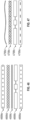
- a single link 1003a,b includes only male or female engagers 1014b, 1028a (though the link can be designed to include both male and female engagers as described elsewhere).
- the female engagers 1028 can include a plurality of serrations on an inner section thereof (the top and bottom flanges are shown removed on some engagers 1028 for clarity) that are configured to interlock with serrations on the male engagers 1014.
- the links 1003a,b can be made out of a metal sheet.
- the links 1003a,b can be laser cut, waterjet cut, stamped, EDM cut, or photochemically etched. Further, thickness of the links can be in the range of 0.004" to 0.010".
- FIGs 11A-11B Similar serrated male and female engagers 1114, 1128 are shown in Figures 11A-11B , respectively.
- the male and female engagers 1114, 1128 each include a ball joint that can be connected with sockets as described with respect to other embodiments above.
- Figures 29A-29G show various embodiments of serrations ( Figure 29A shows serrations with an intermediate angle, Figure 29B show serrations with a steep angle, Figure 29C show serrations at a shallow angle, Figure 29D shows orthogonal (shear) serrations, FIG. 29E shows curved or wavy serrations, Figure 29F shows offset serrations, and Figure 29G shows micro-embedded serrations for added friction).
- FIG. 12 Another embodiment of an overtube 1200 is shown in FIG. 12 .
- the links include plastic male engagers 1214 and female engagers 1228 that are a hybrid of both metal and plastic elements.
- the links can include a plurality of the engagers, where each engager is substantially the same and includes a male portion on one side and a female portion on the other side such that neighboring male and female portions can interlock with one another.
- FIG. 13 shows a plurality of wedge engagers 1313 that are movable axially relative to one another when not constrained, but lock relative to one another when constrained (e.g., by pulling vacuum). These wedges have mating angulated surfaces that are below the critical locking angles, such that they release when vacuum is released.
- FIG. 14 shows a plurality of engagers 1414 shaped to lock relative to one another when constrained.
- the links 1503 can include a plurality of straight (or otherwise non-interlocking, including keystone) engagers 1515.
- An outer ring 1545 or sheath can be used to hold the engagers 1515 of each link in-plane (i.e., such that the engagers 1515 do not move out and over one another).
- the outer ring 1545 can be, for example, a split ring that closes tighter when vacuum is applied (as shown in the transition between Figures 15A and 15B ).
- a spiral wire 1616 can extend around the links 1503 and can be attached to each link, for example, over the mounting ring 1622.
- the spiral wire 1616 can ensure that the outer rings 1545 stay in place (i.e., don't move axially).
- the straight or non-interlocking engagers 3015 can be shaped like keystones, i.e., can form a substantially solid annular member when vacuum is fully applied.
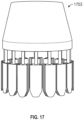
- the end link 1703 can include a taper configured to create an atraumatic end for the overtube.
- This tapered tip region could be elastomeric, so that it tracks easily as the system advances around torturous shapes.
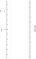
- the inner tube 1801 can be reinforced with a metal, plastic, or fiber. It can be a braid or a spiraling coil 1818 extending therethrough. This reinforcement different cross-sections, including circular, square, elliptical, or rectangular.
- the links for the overtubes described herein can be manufactured in an annular configuration, e.g., by insert molding.
- the linkage 903 can be built flat and then wrapped to form the assembled annular linkage.
- each male engager 2214 can include a bump 2222 or extension extending radially therefrom and positioned near the free end of the male engager 2214.
- each female engager 2228 can include tabs 2244a,b extending laterally or circumferentially therefrom. As the male engager 2214 is pulled axially out of the female engagers 2228a,b, the bump 2222 can hit the tabs 2244a,b to prevent the male engagers 2214 from pulling too far axially out of alignment with the female engagers 2228a,b.
- Figures 38A-D and 39A-B show similar engager limit stops.
- both the male engagers 2314 and the female engagers 2328 can include bumps 2322a,b,c or extensions extending radially therefrom and positioned near the free end of the engagers 2314, 2318.
- An o-ring 2323 can be positioned between the bumps 2322a,b on the female engagers 2328a,b and the bump 2322c on the male engager 2314 such that the bumps 2322a,b,c will hit the o-ring 2323 when the engagers 2314, 2328 have been pulled axially apart by a set distance, thereby preventing the male engagers 2314 from pulling too far axially out of alignment with the female engagers 2328a,b.
- each male engager 3814 can include a flange 3838 extending laterally or circumferentially from the free end of the engager 3814.
- each female engager 3828 can include a cut-away at the proximal end thereof (i.e., at the end connected to the pivot) in the radial center of the engager 3828 such that an inner ledge 3881 is formed.
- the male engager 3814 and female engager 3828 can slide relative to one another (e.g., be pulled axially relative to one another) until the flange 3838 hits the ledge 3881 (shown in Figures 38A-38B ), thereby preventing the male engager 3814 from pulling out of alignment with the female engager 3828.
- each male engager 3914 can include a flange 3939 extending radially from the free end of the engager 3914.
- each female engager 3928 can include a cut-away at a proximal end thereof (i.e., at the end connected to the pivot) in the inner or outer surface such that an inner or outer ledge 3991 is formed.
- the male engager 3914 and the female engager 3928 can slide relative to one another (e.g., be pulled axially relative to one another) until the flange 3939 hits the ledge 3991 (shown in FIG. 39A ), thereby preventing the male engager 3914 from pulling out of alignment with the female engager 3928.
- a mounting spiral 2626 can be used to mount the linkages and/or engagers as opposed to a plurality of individual mounting rings.
- the mounting spiral 2626 can extend substantially the entire length of the overtube 2600.
- any portion of the linkages described herein, including the engagers, can be plated.
- a metallic coating can cover all or part of the linkage 4003 (or any linkage described herein).
- the metallic coating can enhance the stiffness and provide enhanced engagement between engagers 4014, 4028.
- the metallic coating can be aluminum, stainless steel, or titanium.
- the coating can be, for example, 1000-2000 angstroms thick, such as around 1500 angstroms thick
- the engagers can include a friction enhancing plastic to aid in engagement.
- the engagers can include styrene butadiene block copolymer (SBC) with an impact modifier.
- SBC styrene butadiene block copolymer
- the use of SBC could advantageously combine the appropriate balance of strength and stiffness while maintaining high material-on-material grabbing or engagement.
- the pivots described herein can advantageously provide an engineered combination of high axial tensile and compression stiffness and high resistance to shear loads while providing a low bending force.
- This enables the links to conform to the bending of the inner tube, such that the entire system maintains the requisite high flexibility when it is not in the rigidized condition.
- the pivots can exhibit bending force of less than or equal to 35 grams, 20 grams, 10 grams, 5 grams, or even 1 gram. These values are attained wherein the bending force is the load required to deflect the element 45 degrees and the load is applied 1cm from its attachment.
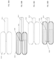
- the male and female engagers described herein can work by having a gap therebetween when no vacuum is applied ( Figure 27A ) and little or no gap when vacuum is applied ( Figure 27B ).
- a rigidizing overtube can include links with extendable locking pivots in place of the engagers described herein.
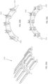
- the linkage system 3201 (for use as part of an overtube with an inner tube, outer tube, vacuum pump, etc. as described above) can include a plurality of linkages 3203a,b,c.
- the linkages 3203a,b,c can be connected to each other through a pivot point 3232 or pivot points 3232a,b,c,d (which can be, for example, wire pivot points).
- Each pivot point 3232 can allow bending with one degree of freedom between linkages ( Figure 32D shows the bend at pivot points 3232a,b while Figure 32F shows the bend at pivot points 3232c,d).
- linkages 3203a,b,c can be arranged in alternating fashion with every other linkage connected with the pivot points 3232 positioned 90 degrees away from the previous linkage (see, e.g., pivot points 3232a,b connecting linkages 3203a,b relative to pivot points 3232c,d connecting linkages 3203b,c).
- Each linkage 3203 can have cut-outs at the proximal and distal ends thereof extending from the pivot-points to as to allow bending of the linkages relative to one another (see, e.g., cut-out space 3299 between linkages 3203c and 3203d).
- each linkage can be connected to a neighboring linkage by a respective tensile member 3288 (only one tensile member is labeled for clarity).
- the tensile member 3288 can be fixed relative to one linkage (e.g., linkage 3203c) and movable within a track of the neighboring linkage (e.g., within track 3277 of linkage 3203b). Movement of the tensile member 3288 within the track 3277 allows the tensile member 3288 to lengthen when on the outside of the curve and shorten when on the inside of the curve during bending of the overtube.
- a clamp 3266 can be attached to the tensile member 3288, which can move within the track 3277 as well.
- the outer sleeve compresses the clamp 3266 onto the link 3203b and keeps the clamp 3266, and therefore the tensile member 3288, from moving. Since the tensile member 3288 cannot move upon application of the vacuum, the links 3203c,d cannot bend around the pivots 3232c,d, causing the linkage system 3201 to adopt a fixed or rigid configuration. When vacuum is removed, the clamp 3266, tensile member 3288, and links 3203 are free to move relative to one another.
- the linkages 3203 can be shaped to allow for a specific degree of bend before travel is stopped, which can be called angled theta ( ⁇ ).
- Theta can be allowed to change freely when the overtube is in the flexible configuration and can become fixed when the overtube is in the rigid configuration (i.e., when vacuum is pulled).
- the tensile member 3288 can slide relative to one or both links 3203c,d.
- rigid the tensile member 3288 is fixed relative to both links 3203c,d.
- the tensile member 3288 can bridge the gaps on both sides of the device (e.g., can run along one gap and then 180 degrees along the opposite gap). In some embodiments, however, the member can be a rigid member that is configured to handle both compression and tension. In such embodiments, the compression/tensile member need only run along one side of the gap. When bending loads are applied in one direction, the member will be under compression but will not buckle. When bending loads are applied in the other direction, the member will be in tension but will not buckle.
- male/female engagers as described herein can bridge the gap, moving axially relative to each other without vacuum and locking in place when vacuum is applied.
- FIG. 55A-55E Another exemplary linkage system 5501 is shown in Figures 55A-55E .
- the linkage system 5501 similarly include a plurality of linkages 5503a,b,cd connected to each other with tensile members 5588 and pivot points 5533.
- the tensile members 5588 of system 5501 are each flexible and can bend 180 degrees to allow for bending over the linkage system 5501 in all directions.
- the tensile member 5588 can be fixed at one end (i.e. relative to one linkage (e.g., at location 5555)) and movable at the opposite end with respect to a neighboring linkage.
- the linkage system 5501 can include engagers at the movable end of each tensile member 5588 that allow movement of the tensile members 5588 (and thus bending/movement of neighboring linkages 5503 relative to one another). That is, each tensile member 5588 can be connected to (or formed from) a male engager 5514 (which can be any of the male engagers described herein). The connection point of the tensile member 5588 to the neighboring linkage 5503 can be via a female engagers 5528 (which can be any of the female engagers described herein) that are configured as part of the clamps 5566.
- the male engagers 5514 can be wedge-shaped on either side while the female engagers 5528 can include corresponding wedge-shaped cut-outs. Movement of the tensile member 5588 using the engagers allows the tensile member 5588 to lengthen when on the outside of the curve and shorten when on the inside of the curve during bending of the overtube.
- the outer sleeve compresses the clamp 5566 onto the tensile member 5588 to prevent the tensile member 5588 from moving. Since the tensile member 5588 cannot move upon application of the vacuum, the links 5503 cannot bend, causing the linkage system 5501 to adopt a fixed or rigid configuration. When vacuum is removed, the clamp 5566, tensile member 5588, and links 5503 are free to move relative to one another.
- the linkages of the pivot locking systems can be 0.4 inches long with a maximum bend angle of +/-40 degrees from neutral (roughly 1.5" bend radius).
- the tension member can be a UHMWPE fiber bundle.
- the tensile member can be wrapped within the track 1.5 times to provide capstan drag and boost the clamping force.
- the clamp can have a surface area of roughly 0.15" x 0.4" to maximize vacuum force while allowing for +/- 40 degrees of bending.
- the clamp can be smooth and rely solely upon friction to hold the tensile member in place.
- the inner sleeve can be 50A urethane 0.010" thick and is bonded periodically to the inner surface of the links.
- the outer sleeve can be 50A urethane 0.010" thick and is a clearance fit on the outside of the links with no attachment to the links.
- the clamp described herein can be attached to the tensile member or can clamp down onto the tensile member. Further, the clamp may push down radially or axially onto the tensile member. In some embodiments, the clamp can include serrations on the bottom thereof to mate with the link.
- the tensile member can be fiber, string, thread, wire, or cable. In some embodiments, the tensile member can be a continuation of the pivot cable or thread. Further, in some embodiments, there can be two tensile members that undergo axial translation instead of rotation. In such an embodiment, two clamps can be used on each link to clamp both tensile members down.
- the extendible locking pivot design can advantageously have high torsional stiffness, high compression stiffness, and high tensile stiffness with or without vacuum. Further, such designs can have high flexibility for small bend radii, can have a small diameter, and can have a substantially circular cross-section.
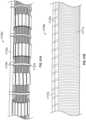
- the outer layer of the overtubes described herein can include a braid therein or therearound.
- the outer layer 3605 can include a braid 3636 therein to provide greater torsional stiffness, shear stiffness under vacuum, and tension without vacuum without substantially affecting the unvacuumed bending stiffness of the overall device.
- the braid 3636 can advantageously help smooth over the outside of the engagers to make the device more patient-friendly.
- the braid 3636 can be made, for example, of fiber, metal, or plastic. Further, the braid 3636 can include round strands, flattened strands, or a combination of the two.
- the braid can be layered on top of other layer(s) of braid.
- Braid angles can be precisely engineered, for example, to 10 to 30 degrees, with zero degrees being in-line with the major tube axis and 90 degrees being orthogonal to that access.
- Braid filaments can be of plastic or metal, such that it exhibits good tensile and compression properties.
- the filaments can be homogenous, or they can have a base material coupled with a surface treatments, for example for enhanced gripping.
- Fibers can be utilized for enhanced tensile properties.
- Cross sections can be multiple geometries, including round, square, or rectangular.
- the braid can include 48 strands of 0.002" by 0.02" PET flat filaments braided with a 0.7" nominal diameter at a 45 degree braid angle.
- hoop strands 3737 can be incorporated into a braid 3736 to provided increased stiffness when loaded in compression.
- the hoops strands 3737 can be, for example, woven through the strands of the braid 3736 (e.g., alternately over two strands of the braid and under two strands of the braid). Additionally, the presence of an undersurface (e.g., the links) enables the braid 3736 to resist torsion in both twisting directions and to resist tensions when there is no vacuum on the system.
- the slip layer can be made of low coefficient of friction materials, such as thin film fluoropolymers (FEP, chemfilm, PTFE, with thicknesses as low as 2, 4, 6 microns).
- the slip layer(s) include powders, such as talcum or cornstarch.
- the slip layer(s) can be a coating.
- the slip layer(s) can be slip additives added to an elastomer.
- the slip layer(s) can be sheaths of thin plastic films that are inherently lubricious, such as low-density polyethylene (LDPE).
- LDPE low-density polyethylene
- the slip layer is made of a thin spiral-wrapped film, such at .0005" FEP or .00025" Chemfilm (St. Gobain).
- engagers can be photo-etched. In some embodiments, engagers can be etched down, welded, or vacuum furnace diffusion bonded.
- the wire pivots can be spot welded to the engager and/or the mounting ring.
- any of the links described herein can advantageously be thin and made of a highmodulus material (i.e., a material with a modulus over 200ksi. They could be made of a material of very high modulus, for example LCP (Liquid Crystal Polymer), or stainless steel. Should the links be comprised of lower modulus materials, their stiffness could be augmented through the selective insertion of members of higher stiffness (i.e., insert molded cables or wire).
- a highmodulus material i.e., a material with a modulus over 200ksi. They could be made of a material of very high modulus, for example LCP (Liquid Crystal Polymer), or stainless steel.
- LCP Liquid Crystal Polymer
- the links be comprised of lower modulus materials, their stiffness could be augmented through the selective insertion of members of higher stiffness (i.e., insert molded cables or wire).
- the links can be relatively short, for example, for a colonoscopy application with a pitch length of 0.8, 1 1.2, or 1.4" long.
- the overtube length can be approximately 95 cm long. Being short helps the system to not suffer from capstan drag effects, i.e., the cumulative exponentially-rising drag that occurs when long members accumulative successive wraps. Moreover, because this design does not suffer from capstan drag, it does not lose stiffness as a function of increasing length from the base handle.
- the overtube can have, for example, a length of 95cm to accommodate a colonoscope, but the relatively short links allow the bend differential to be taken up locally, allows bending easily and smoothly (i.e.
- the circumferential difference between the inner and outer bend radius can be realized locally at each individual link as the engagers move past each other).
- the links (or series of engaged links) described herein can further be configured so as to effectively carry both tensile and compressive loads without deforming, deflecting, or buckling when a load is applied.
- the overtubes described herein can including steering elements to aid in moving the overtube through the body lumen when the overtube is in the flexible configuration.
- the overtube 2400 (which can include any of the rigidizing and other features described herein) can include cables 2424 extending therethrough that can be connected, for example, through anchoring rings. Applying tension on the cables 2424 when the overtube 2400 is in the flexible configuration can create compression in the overtube 2400, thereby causing it to bend in the direction of the applied compression.
- the overtube 2500 can be separable into chambers.
- Each chamber can be controlled by a separate vacuum (and/or without vacuum) to allow independent rigidizing of chambers. That is, as shown in Figure 25 , there can be a first vacuum chamber (with its own vacuum line 2523) that controls the proximal portion 2526 and a second vacuum chamber (with its own vacuum line 2527) that controls the distal portion 2521.
- a pressure seal 2529 can separate the two chambers of proximal portion 2526 and distal portion 2521.
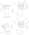
- the overtube 5700 can have both separate chambers and a steerable distal end.
- Pressure seals 5729 can extend between each chamber.
- the distal anchor point 5757 can also include a pressure seal.
- the cables 5724 can be managed using cable guides (e.g., at least one, such as 1-4 cable guides in each vacuum chamber 5775).
- the overtube 5700 thus includes multiple zones of rigidization (via chambers 5775) and cables 5724 that extend the entire length of the overtube 5700, but are anchored only at the tip 5757. Any vacuum zones that are in the flexible state can be steered or deflected in the direction of cable tension while the zones that are rigidized will remain in their position and not be deflected.
- this design allows alternating of which zones are under vacuum and/or direction of steering to form very complex shapes and provide navigation through the anatomy with minimal looping.
- a cross-section of the overtube 5700 is shown in Figure 57A .
- the cables 5727 and/or vacuum lines 5724 can extend, for example, in a radial gap 5797 or space between the inner tube 5701 and the engagers 5714/5728 (and thus can also extend beneath the vacuum sheath 5705).
- the cables 5727 and vacuum lines 5724 can extend within the central opening of the overtube 5700 (cable guides 5799 are also shown in Figure 57C ). It should be understood that the overtube 5700 can also be part of a scope.
- the overtube 4200a can include an outer coil 4241a wound therearound (e.g., at the distal end of the overtube 4200a).
- Axially aligned loops 4261a can be positioned at each wind of the coil 4241a.
- a pull-cable 4262a can be routed through each loop 4261a. As tensile load is applied to the pull-cable 4262a, the tube 4200a can bend into an arc, thereby providing steerability of the overtube 4200a.
- the overtube 4200b can include rigid links 4263b connected together via pivots 4264b (e.g., a wire pivot).
- a pull-cable 4262b can be attached to the links such that as a tensile load is applied to the pull-cable 4262b, the tube 4200b can bend into an arc, thereby providing steerability of the overtube 4200b.
- the overtube can include motors or other features (e.g., sensors, communication, computation, illumination) for steering or stabilizing individual links or segments.
- motors or other features e.g., sensors, communication, computation, illumination
- the overtubes described herein are in the rigid configuration can advantageously maintain shape despite loads being placed therein.
- the overtube in the rigid configuration, can hold its shape or angles against applied torque of greater than 1Nm, 2Nm, or 3Nm.
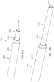
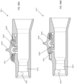
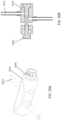
- the handle 3131 includes a vacuum line 3132 for providing vacuum to rigidize the overtube, a lubrication line 3133 to provide lubrication between the overtube and the scope, a vacuum seal bond 3134, and a lubrication seal 3135.
- a similar handle 4831 is shown in Figures 48A-48D .
- the handle 4831 includes an activation element (button 4848) configured to activate the vacuum (the button is shown off in Figures 48A and 48C and on in Figures 48B and 48D ).
- flow path within the handle 4831 can include a vacuum input port 4849 configured to be attached to the vacuum source, an overtube port 4850 that connects to the overtube via output 4853, and a vent port 4851 that connects to atmosphere.
- the button 4848 is in a distal "off' position (i.e., such that vacuum to the overtube is supposed to be off)
- the vent port 4851 and overtube port 4850 are in communication with one another.
- the handle 4831 can be configured to be bonded to the overtube (e.g., to an inner coil wound tube over the overtube) at bonding region 4853.
- the handle includes a status indicator to indicate whether the overtube is in the flexible or rigid configuration.
- the status indicator is such that the word "on” shows when the button is placed in the "on” position, and the word “off' shows when the button is placed in the "off' position.
- the status indicator can be a symbol, color, light, or moving indicator.
- the activation element can be a button, switch, toggle, slider, screwed connection, squeeze handle, or stop-cock. Further, the activation element can be planar, a sector, or omnidirectional. Further, the indicator element can include words, lights, or an element that spins with flow of vacuum.
- one or both can be on separate elements.
- the activation element can be positioned along the vacuum line between the handle and the vacuum pump, can be actuated by a foot pedal, can be on the scope umbilical, or can be clipped on the patient's bed.
- Having the indicator element and/or activation element separate from the handle can advantageously allow the actuator and indicator to be seen more clearly (i.e., not be obstructed by the person's anatomy) and/or can allow the actuator and indicator to be controlled/used more easily by an additional person (e.g., a procedural assistant).
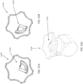
- Figures 56A-D show a handle 5631 that is designed to allow manipulation of an overtube, but that does not include an activation element or an indicator element.
- the handle 5631 includes a large flange 5661 at the distal end thereof that can prevent the handle 5631 to act as an insertion blocker (i.e., to stop the handle from moving into the anatomy) and to act as a face against which the operator can push during use.
- the overtube can connect at bond region 5663.
- the handle 5631 can include an input 5665 from the actuator connected to an output 5667 to the overtube.
- the activation element 5048 can be a spool valve that is shuttled in one direction to activate the vacuum in the overtube and can be shuttled in the opposite direction deactivate the vacuum. When preventing vacuum to the overtube, the activation element 5048 can provide venting.
- the actuator 5048 can be positioned on the vacuum line 5032 leading to the handle, such as 4"-8", e.g., 6" away from the handle.
- the spool valve with end button indicator element 5050 can indicate that the overtube is in the flexible configuration (as shown) or the rigid configuration (when pushed in the opposite direction).
- the activation element 5148 can be a rotary valve (e.g., connected to the handle or elsewhere as described herein). Further, a sliding indicator 5150 can show that the vacuum is on (as shown in Figures 51A and 51C ) or off (as shown in Figure 51B ).
- FIG. 52A-52C Another spool valve actuation element 5248 is shown in Figures 52A-52C .
- the element 5248 can be similar to element 5048 except that it can include an attachment mechanism 5252 (e.g., a c-shaped clip) for detachable coupling to a handle 5231.
- an attachment mechanism 5252 e.g., a c-shaped clip
- the actuation element 5348 can be a slider element.
- the actuation element 5348 can include a connection element 5353 (e.g., a hollow tube or snap-fit element) configured to slide over a handle.
- the indicator element 5350 can be built into the slider (e.g., indicate "rigid” when the slider is in one position and “flexible” when the slider is in another position).
- a similar slider actuation element 5448 (this one orthogonal) can be seen in Figures 54A-54C .
- the vacuum can be applied through a manual pump and valve system rather than through an automated vacuum pump or wall vacuum source.
- the manual pump can be part of the overtube.
- the handle can include a vacuum indicator.
- a handle for the overtube can be bonded to the midsection of the proximal most link. Strain relief heat shrink or an elastomer can be placed over the joint.
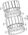
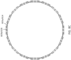
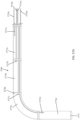
- FIG. 19 shows an endoscope 1919 extending through an overtube 1900 (without an outer sheath for clarity) that is in a rigid configuration (here, shown as a looped configuration). Because the overtube 1900 is rigid, the endoscope 1919 can easily move or slide therethrough. Thus, the rigid overtube 1900 can be used to counteract the reactive forces that would otherwise occur on the scope as the scope moves through the anatomy.
- overtubes/rigidizing devices described herein can toggle between the rigid and flexible configurations quickly, and in some embodiments with an indefinite number of transition cycles. As interventional medical devices are made longer and inserted deeper into the human body, and as they are expected to do more exacting therapeutic procedures, there is an increased need for precision and control. Selectively rigidizing members or overtubes as described herein can advantageously provide both the benefits of flexibility (when needed) and the benefits of stiffness (when needed).
- an overtube as described herein can be introduced to the patient in the flexible configuration over the endoscope, then steered towards the desired anatomy. Once the distal end of the overtube is positioned past the challenging anatomy (i.e., that portion that tends to cause looping), the overtube can be transitioned to the rigid configuration. The scope or other instrument can then be advanced through the challenging or looped anatomy.
- the overtube 2000 can be used to extend through the sigmoid colon 2020.
- the overtube 2000 can be extended past the curves S1 and S2 in the flexible configuration. Vacuum can then be pulled to transition the overtube 2000 to the rigid configuration, allowing the endoscope to be passed therethrough. This could be performed with or without a sigmoid reduction.
- the overtubes described herein can also be used, for example, elsewhere in the gastrointestinal tract, in the vascular system (including over the aortic arch), or into the peritoneal cavity.
- the dynamically rigidizing mechanisms described herein can be used with other medical technologies as well.
- the dynamically rigidizing mechanisms can be incorporated directly into the shaft of an endoscope and/or can be used as part of a catheter, probe, or surgical guide.
- the overtubes/ rigidizing devices described herein can be used to stiffen a guide sheath in interventional cardiology or structural heart cases.
- the overtubes/rigidizing devices can be used to provide a "rail" for the transcatheter aortic valve replacement (TAVR) device, thereby keeping the tip of the TAVR catheter from scraping and skiving the top of the aortic arch where there is often thrombus burden (current systems tend to ride the outside of the arch, rubbing against plaques, creating embolic storms).
- TAVR transcatheter aortic valve replacement
- the overtubes/rigidizing devices can help enable superior alignment and placement as well as lower paravalvular leakage and optimal placement relative to pacing nodes.
- the overtubes/ rigidizing devices described herein can be used to deliver a mitral valve replacement. That is, crossing the septal wall during mitral valve replacement can be particularly difficult, as it involves multiple curves, a beating heart, and the need for precisely aligned entry and stabilization before delivery of the implant.
- Current valve delivery platforms can be quite rigid, which can be dangerous for anatomy that it straightens (such as the femoral artery, which can be highly calcified and friable).
- the overtubes/rigidizing devices described herein can advantageously create a conduit that goes in flexibly, then rigidizes in whatever shape the particular person's anatomy provided, such that the overtube/rigidizing device conforms to the entire anatomical track.
- the overtubes/rigidizing devices described herein can allow the clinician to create a stable mechanical lumen leading directly to the anatomy, to locate it without significant local anatomical load, then to stabilize rigidly in that shape as a device is delivered through it.
- the rigidizing devices can be incorporated into catheters for interventional cardiology, such that they track very easily (flexible), then can be rigidized for instances when the device is used to push through locally anatomy, including CTOs (Chronic Total Occlusions).
- the overtubes/rigidizing devices described herein can be used to stiffen an overtube for gastroenterology, such as to stiffen an endoscope.
- the overtubes/rigidizing devices described herein can be integrated into an endoscope such that the endoscope can be selectively rigidized.
- the overtubes/rigidizing devices described herein can be utilized to perform therapies during esophagogastroduodenoscopy (EGD), for example, on the roof of the stomach.
- EGD esophagogastroduodenoscopy
- the overtubes/rigidizing devices described herein can be used to create more optimal access and stabilization during ERCP (Endoscopic Retrograde Cholangiopancreatograpy), including the kinematically and clinically challenging tasks of cannulating the ampulla.
- ERCP Endoscopic Retrograde Cholangiopancreatograpy
- the overtubes/rigidizing devices described herein can be used to create an overtube for enteroscopy.
- Enteroscopy is kinematically challenging for several reasons, including because the scopes are relatively small diameter (9 mm), they are very long (2 meters), and they frequently loop as they navigate the gastrointestinal tract to get to the small intestine starting line (either the pylorus or the terminal ileum).
- the overtubes/rigidizing devices described herein can be used in conjunction with other versions of the product.
- an endoscope can include the rigidizing mechanisms described herein
- an overtube can include the rigidizing mechanisms described herein. Used together, they can create a mother-daughter system that can advance, one after the other, allowing one of the elements to always remain stiffened, such that looping is reduced or eliminated.
- the overtube can have an inner diameter of .52" and an outer diameter of .71", thereby providing room for a scope to extend therethrough while also allowing the scope to extend through the desired body lumen.
- the inner diameter can be as low as 0.10"-0.12".
- a system 2121 can include an overtube 2100 and a scope 2191 that are axially movable relative to one another, either concentrically or non-concentrically. Further configurations could be constructed, including rigidizing elements, steerable elements, an endoscope, and lumen(s) for instruments.
- the overtube 2121 can be configured as described elsewhere herein (e.g., with links, engagers, etc.).
- the scope 2191 can include an outer shaft that includes the rigidizing elements as described herein.
- Each of the overtube 2121 and the scope 2191 can include an outer layer 2105 and a cover 2110 (such as a coil wound tube), respectively (the outer layer 2105 and cover 2110 have been removed in Figure 21C for clarity).
- the overtube 2100 can include, for example, rigidizing features as described elsewhere, such as male and female engagers 2114, 2128 that can engage and lock when vacuum is pulled on the system.
- the male and female engagers 2114, 2128 can be positioned around a coiled flexible inner tube 2101.
- a gap 2171 can be present between the overtube 2121 and the scope 2191 to allow for sliding.
- the shaft of the scope 2191 can include rigidizing elements, such as inner wedges 2152 and outer wedges 2153 configured to engage and lock when a vacuum is pulled.
- An inner sheath 2150 can separate and seal the wedges 2152 and 2153 from the inner working 2161 for scope features.
- the system 2121 can be used to facilitate movement through a tightly curved body lumen.
- the scope 2191 can be inserted into the curved area and bent or steered into the desired shape. Vacuum can be applied to the scope 2191 to causes the wedges 2152, 2153 to engage and lock the scope 2191 in the configuration.
- the overtube 2100 can then be advanced over the rigid scope 2191. When the overtube 2100 reaches the tip of the scope 2191, vacuum can be applied to the overtube 2100 to cause the male and female engagers 2114, 2128 to engage and lock to fix the shape of the overtube.
- the scope 2191 can be advanced and the process repeated.
- system 2121 is described as including an overtube and a scope, it should be understood that other configurations are possible.
- the system might include two overtubes, two catheters, or a combination of overtube, catheter, and scope.
- the overtubes described herein can include a built-in working channel to allow the user to perform procedures with additional features, including the use of more tools, traction, enhanced insufflation, suction, or wash.
- the working channel can be positioned within the vacuum layer or outside of the vacuum layer.
- an overtube 4100a can include a plurality of small rings 4124a attached to the link mounting rings 4122a.
- a tube 4142a can extend the length of the overtube 4200a and can be held by the rings 4124a.
- the tube 4142a can be a telescoping tube to provide more flexibility as the overtube 4100a bends. The tube 4142a can thus function as a working channel for the overtube 4100a.
- an overtube 4100b can include a bendable layer 4171b (e.g., with linkages as described herein), a tube 4142b attached thereto, and a thin sheet 4172b (e.g., an elastomeric sheath) thereover.
- the tube 4142b can be, for example, a spiral-slit tube to allow the tube 4142b to bend to a certain radius without substantially stressing the bendable layer 4171b.
- the thin sheet 4172b can provide vacuum sealing for the overtube 4100b.
- bellows can be used for the working channel.
- an overtube 4100c can include a tube 4142c that extends between engagers (e.g., in place of one or more engagers at each linkage).
- the tube 4142c can be held down, for example, with u-shaped connector 4148c at each linkage.
- an overtube 4100d can include a tube 4142d that similarly extends between engagers (e.g., in place of one or more engagers at each linkage).
- the tube 4142d can, for example, be a telescoping tube with smaller diameter portions sliding within the larger diameter portions.
- Figures 43-47 show various layered embodiments.
- Figure 43 shows the wall of an overtube that includes layers 4399a-f.
- Inner layer 4399a can be a coil-wound tube or extrusion
- layer 4399b can be a slip layer
- layer 4399c can be a braid
- layer 4399d can be fiber-wound hoops (either woven in or on top of the braid of layer 4399c)
- layer 4399e can be the linkages
- outer layer 4399f can be an outer sheath (e.g., made of urethane).
- Figure 44 shows the wall of an overtube that that includes layers 4499a-d.
- the inner layer 4499a can be a coil wound tube
- layer 4499b can be the linkages
- layer 4499c can be a braid
- outer layer 4499d can be fiber-wound hoops.
- Figure 45 shows the wall of an overtube that includes layer 4599a-c.
- Inner layer 4599a can be a coil-wound tube
- layer 4599b can be the linkages
- outer layer 4599c can be an outer sheath.
- Figure 46 shows the wall of an overtube that includes layers 4699a-e.
- Inner layer 4699a can be a coil wound tube
- layer 4699b can be the linkages
- layer 4699c can be a thin sheath
- layer 4699d can be a braid
- outer layer 4699e can be fiber-wound hoops (e.g., embedded in polymer).
- Figure 47 shows the wall of an overtube that includes layers 4799a-4799d.
- Inner layer 4799a can be a coil wound tube
- layer 4799b can be the linkages
- layer 4799c can be a braid
- outer layer 4799d can be a sheath.
- layer 4399a can be followed by slip layer 4399b, one, two, three or four layers 4399c of braid, and an outer layer formed by layer 4399f.
- the male and female engagers can be configured to unlock when vacuum is released.
- This unlocking can be achieved passively by the proper combination of material and design (e.g., angle of wedges).
- the unlocking can be achieved actively by forcing engagers apart when vacuum is removed.
- a spring-like feature such as an elastomer, can be placed below the engagers (e.g., radially inward of the engagers) to push the engagers out and away from one another when vacuum is removed.
- the engagers can be configured to be "floating" or adjustably attached to the mounting ring (e.g., via a spring). Floating engagers can advantageously allow for both strong engagement and the strong release requisite for proper free-sliding between engagers.
- the engagers can be bonded directly into the underlying tube.
- the friction of the engagers can be increased by using a fiber filled elastomer (e.g., glass or carbon), polystyrene, SBC, metallization (Ti, Al, Copper, SS), physical vapor deposition (PVD) (Au, Ag), adding powder or dust or abrasives.
- a fiber filled elastomer e.g., glass or carbon
- polystyrene SBC
- metallization Ti, Al, Copper, SS
- PVD physical vapor deposition
- Au Ag
- the COF numbers can range from 0.4 to 2.0.
- the mounting rings can have a modulus of greater than 0.5 msi with inserted molded cable pivots.
- the cable pivot gaps can be short so that the wire can bend in a cone of motion but not buckle or deform.
- the engagers can have a modulus of 0.2msi - 0.5msi, such as 0.4msi.
- the female engagers can be I-beams and therefore have high stiffness.
- the male engagers can be of sufficient stiffness to flex to allow for properly alignment, but stiff enough so as not to buckle.
- the engagers can be configured so as to not slip under vacuum.
- the tip of the overtube can include a balloon, cage, or suction at the tip for local tissue stabilization.
- the overtube can have a customizable length where by the appropriate number of segments are chosen and assembled.
- the overtubes described herein can be configured to be loaded over the side of the scope or other instrument (e.g., rather than requiring insertion of the scope/instrument into the proximal end of the overtube).
- the overtube 4900 can be split along the length thereof (i.e., split longitudinally through the wall from the proximal end to the distal end).
- a connection feature 4944 can connect the split wall together.
- the connection feature 4944 can be reusable.
- the connection feature 4944 can be a series of magnets that can engage ( Figure 49A ) to hold the overtube 4900 together and disengage ( Figure 49B ) to provide side access for the scope/instrument.
- Other exemplary reusable connection features include zippers, interlocking zip-lock male and female configuration, or reusable tape.
- the connection feature 444 can be permanent and not reusable, such as permanent tape or adhesive.
- an additional layer can be placed over the outer layer.
- the additional layer can have a higher modulus material or can be fiber-reinforced relative to the outer layer.
- high pressure can be introduced, which can create an enhanced pressure of the outer layer against the engagers to keep high friction and to help prevent the overtube it from buckling.
- overtubes or rigidizing devices and systems described herein can be used, for example, with classic endoscopes, colonoscopes, robotic systems, and/or navigation systems, such as those described in International Patent Application No. PCT/US2016/050290, filed September 2, 2016 , titled "DEVICE FOR ENDOSCOPIC ADVANCEMENT THROUGH THE SMALL INTESTINE".
- references to a structure or feature that is disposed "adjacent" another feature may have portions that overlap or underlie the adjacent feature.
- the device may be otherwise oriented (rotated 90 degrees or at other orientations) and the spatially relative descriptors used herein interpreted accordingly.
- the terms “upwardly”, “downwardly”, “vertical”, “horizontal” and the like are used herein for the purpose of explanation only unless specifically indicated otherwise.
- first and second may be used herein to describe various features/elements, these features/elements should not be limited by these terms, unless the context indicates otherwise. These terms may be used to distinguish one feature/element from another feature/element. Thus, a first feature/element discussed below could be termed a second feature/element, and similarly, a second feature/element discussed below could be termed a first feature/element without departing from the teachings of the present invention.
- a numeric value may have a value that is +/- 0.1% of the stated value (or range of values), +/- 1% of the stated value (or range of values), +/- 2% of the stated value (or range of values), +/- 5% of the stated value (or range of values), +/- 10% of the stated value (or range of values), etc. Any numerical range recited herein is intended to include all sub-ranges subsumed therein.
Landscapes
- Health & Medical Sciences (AREA)
- Life Sciences & Earth Sciences (AREA)
- Surgery (AREA)
- Engineering & Computer Science (AREA)
- Biophysics (AREA)
- Medical Informatics (AREA)
- Nuclear Medicine, Radiotherapy & Molecular Imaging (AREA)
- Optics & Photonics (AREA)
- Pathology (AREA)
- Radiology & Medical Imaging (AREA)
- Veterinary Medicine (AREA)
- Biomedical Technology (AREA)
- Heart & Thoracic Surgery (AREA)
- Physics & Mathematics (AREA)
- Molecular Biology (AREA)
- Animal Behavior & Ethology (AREA)
- General Health & Medical Sciences (AREA)
- Public Health (AREA)
- Mechanical Engineering (AREA)
- Rehabilitation Therapy (AREA)
- Surgical Instruments (AREA)
- Media Introduction/Drainage Providing Device (AREA)
- Endoscopes (AREA)
Applications Claiming Priority (3)
| Application Number | Priority Date | Filing Date | Title |
|---|---|---|---|
| US201762535134P | 2017-07-20 | 2017-07-20 | |
| US201862672444P | 2018-05-16 | 2018-05-16 | |
| PCT/US2018/042946 WO2019018682A1 (en) | 2017-07-20 | 2018-07-19 | DYNAMICALLY RIGIDING SURFACE |
Publications (4)
| Publication Number | Publication Date |
|---|---|
| EP3654822A1 EP3654822A1 (en) | 2020-05-27 |
| EP3654822A4 EP3654822A4 (en) | 2021-01-06 |
| EP3654822C0 EP3654822C0 (en) | 2023-11-15 |
| EP3654822B1 true EP3654822B1 (en) | 2023-11-15 |
Family
ID=65015334
Family Applications (1)
| Application Number | Title | Priority Date | Filing Date |
|---|---|---|---|
| EP18835355.1A Active EP3654822B1 (en) | 2017-07-20 | 2018-07-19 | Dynamically rigidizing overtube |
Country Status (5)
| Country | Link |
|---|---|
| US (2) | US12295550B2 (enExample) |
| EP (1) | EP3654822B1 (enExample) |
| JP (1) | JP7379321B2 (enExample) |
| CN (1) | CN111065311B (enExample) |
| WO (1) | WO2019018682A1 (enExample) |
Cited By (1)
| Publication number | Priority date | Publication date | Assignee | Title |
|---|---|---|---|---|
| WO2025186256A1 (en) * | 2024-03-04 | 2025-09-12 | Ecole Polytechnique Federale De Lausanne (Epfl) | Variable stiffness catheter for surgical applications, system for remote magnetic navigation surgical approach and method for manufacturing said catheter |
Families Citing this family (22)
| Publication number | Priority date | Publication date | Assignee | Title |
|---|---|---|---|---|
| JP7082052B2 (ja) | 2015-09-03 | 2022-06-07 | ネプチューン メディカル インク. | 小腸内での内視鏡前進の為の器具 |
| US11122971B2 (en) | 2016-08-18 | 2021-09-21 | Neptune Medical Inc. | Device and method for enhanced visualization of the small intestine |
| EP3654822B1 (en) | 2017-07-20 | 2023-11-15 | Neptune Medical Inc. | Dynamically rigidizing overtube |
| US12059128B2 (en) | 2018-05-31 | 2024-08-13 | Neptune Medical Inc. | Device and method for enhanced visualization of the small intestine |
| WO2020018934A1 (en) | 2018-07-19 | 2020-01-23 | Nep Tune Medical Inc. | Dynamically rigidizing composite medical structures |
| KR20210149102A (ko) | 2019-04-08 | 2021-12-08 | 포티메딕스 에셋츠 Ii 비.브이. | 탈착가능한 부분을 포함하는 조향가능한 기구 |
| US11793392B2 (en) | 2019-04-17 | 2023-10-24 | Neptune Medical Inc. | External working channels |
| US12329473B2 (en) | 2019-04-17 | 2025-06-17 | Neptune Medical Inc. | Dynamically rigidizing composite medical structures |
| AU2021245989A1 (en) | 2020-03-30 | 2022-10-27 | Neptune Medical Inc. | Layered walls for rigidizing devices |
| CN115666360A (zh) * | 2020-05-26 | 2023-01-31 | 海王星医疗公司 | 刚性化装置 |
| US11717322B2 (en) | 2020-08-17 | 2023-08-08 | Covidien Lp | Flexible cannula having selective rigidity |
| CN116490240A (zh) * | 2020-09-03 | 2023-07-25 | 海王星医疗公司 | 动态刚性化导轨及使用方法 |
| CA3206945A1 (en) | 2021-01-29 | 2022-08-04 | Garrett J. GOMES | Devices and methods to prevent inadvertent motion of dynamically rigidizing apparatuses |
| JPWO2022181200A1 (enExample) * | 2021-02-25 | 2022-09-01 | ||
| EP4304441A4 (en) | 2021-03-10 | 2025-01-22 | Neptune Medical Inc. | CONTROL OF DYNAMICALLY STIFFENED, COMPOSITE, ROBOTIC MEDICAL STRUCTURES |
| DE102021108188B4 (de) * | 2021-03-31 | 2022-11-10 | Alpaka Technology UG (haftungsbeschränkt) | Video-Endoskop sowie Verfahren zur Überwachung einer Sterilbarriere eines Video-Endoskops |
| CN113183127A (zh) * | 2021-04-19 | 2021-07-30 | 浙江工业大学 | 一种软体机器人抗扭骨架及软体机器人 |
| CN114872082A (zh) * | 2022-03-15 | 2022-08-09 | 哈尔滨工业大学 | 一种自生长软体机器人及其硬化方法 |
| JP2025514183A (ja) | 2022-04-27 | 2025-05-02 | ネプチューン メディカル インク. | 内視鏡用衛生シース |
| CN116570221B (zh) * | 2023-05-31 | 2025-10-31 | 湖南省华芯医疗器械有限公司 | 一种蛇骨结构、主动弯曲段、插入部和内窥镜 |
| WO2025054618A1 (en) | 2023-09-07 | 2025-03-13 | Neptune Medical Inc. | Pressure rigidization apparatuses and methods |
| US12330292B2 (en) | 2023-09-28 | 2025-06-17 | Neptune Medical Inc. | Telescoping robot |
Family Cites Families (462)
| Publication number | Priority date | Publication date | Assignee | Title |
|---|---|---|---|---|
| US2268321A (en) | 1940-11-20 | 1941-12-30 | Wardlyn Corp | Catheter |
| US2767705A (en) | 1954-10-08 | 1956-10-23 | Technical Oil Tool Corp | Sigmoidoscope with suction attachment for immobilizing adjacent tissue |
| US3859986A (en) | 1973-06-20 | 1975-01-14 | Jiro Okada | Surgical device |
| JPS5061890A (enExample) | 1973-10-04 | 1975-05-27 | ||
| US4066071A (en) | 1975-08-15 | 1978-01-03 | Nagel John G | Extension pull through device to allow for easier passage of flexible fiber endoscope |
| US4141364A (en) | 1977-03-18 | 1979-02-27 | Jorge Schultze | Expandable endotracheal or urethral tube |
| US4151800A (en) | 1977-04-15 | 1979-05-01 | The United States Of America As Represented By The Administrator Of The National Aeronautics And Space Administration | Thermal insulation protection means |
| US4176662A (en) | 1977-06-17 | 1979-12-04 | The United States Of America As Represented By The Administrator Of The National Aeronautics And Space Administration | Apparatus for endoscopic examination |
| US4425919A (en) | 1981-07-27 | 1984-01-17 | Raychem Corporation | Torque transmitting catheter apparatus |
| JPS58173558A (ja) | 1982-04-01 | 1983-10-12 | テルモ株式会社 | 医療器具用チユ−ブ |
| SE442377B (sv) | 1984-06-29 | 1985-12-23 | Mediplast Ab | Kateter, sond eller liknande anordning |
| US4690131A (en) | 1985-05-31 | 1987-09-01 | The United States Of America As Represented By The Department Of Health And Human Services | Medical apparatus |
| US4696544A (en) | 1985-11-18 | 1987-09-29 | Olympus Corporation | Fiberscopic device for inspection of internal sections of construction, and method for using same |
| US4961738A (en) | 1987-01-28 | 1990-10-09 | Mackin Robert A | Angioplasty catheter with illumination and visualization within angioplasty balloon |
| US4817613A (en) | 1987-07-13 | 1989-04-04 | Devices For Vascular Intervention, Inc. | Guiding catheter |
| US4794912A (en) | 1987-08-17 | 1989-01-03 | Welch Allyn, Inc. | Borescope or endoscope with fluid dynamic muscle |
| US4890602A (en) | 1987-11-25 | 1990-01-02 | Hake Lawrence W | Endoscope construction with means for controlling rigidity and curvature of flexible endoscope tube |
| US4893613A (en) | 1987-11-25 | 1990-01-16 | Hake Lawrence W | Endoscope construction with means for controlling rigidity and curvature of flexible endoscope tube |
| US4815450A (en) | 1988-02-01 | 1989-03-28 | Patel Jayendra I | Endoscope having variable flexibility |
| US4794412A (en) | 1988-05-16 | 1988-12-27 | Xerox Corporation | Vertical line width control ionographic system |
| DE3829603A1 (de) | 1988-09-01 | 1990-03-15 | Kontron Holding Ag | Ultraschallendoskopeinrichtung |
| US5037404A (en) | 1988-11-14 | 1991-08-06 | Cordis Corporation | Catheter having sections of variable torsion characteristics |
| GB2226245A (en) | 1988-11-18 | 1990-06-27 | Alan Crockard | Endoscope, remote actuator and aneurysm clip applicator. |
| US4959058A (en) | 1989-03-17 | 1990-09-25 | Michelson Gary K | Cannula having side opening |
| US4962751A (en) | 1989-05-30 | 1990-10-16 | Welch Allyn, Inc. | Hydraulic muscle pump |
| US4913369A (en) | 1989-06-02 | 1990-04-03 | Welch Allyn, Inc. | Reel for borescope insertion tube |
| JP2756706B2 (ja) | 1989-07-19 | 1998-05-25 | 旭光学工業株式会社 | 内視鏡の湾曲管部外皮チューブの固定方法及び固定具 |
| DE3935256C1 (enExample) | 1989-10-23 | 1991-01-03 | Bauerfeind, Peter, Dr., 8264 Waldkraiburg, De | |
| US5037386A (en) | 1989-11-17 | 1991-08-06 | Minnesota Mining And Manufacturing Company | Pressure sensing scope cannula |
| US5019121A (en) | 1990-05-25 | 1991-05-28 | Welch Allyn, Inc. | Helical fluid-actuated torsional motor |
| US5018436A (en) | 1990-07-31 | 1991-05-28 | Welch Allyn, Inc. | Folded bladder for fluid dynamic muscle |
| US5193525A (en) | 1990-11-30 | 1993-03-16 | Vision Sciences | Antiglare tip in a sheath for an endoscope |
| US5123421A (en) | 1991-01-16 | 1992-06-23 | C. R. Bard, Inc. | Liquid activated steerable catheter guidewire |
| US5244619A (en) | 1991-05-03 | 1993-09-14 | Burnham Warren R | Method of making catheter with irregular inner and/or outer surfaces to reduce travelling friction |
| US5251611A (en) | 1991-05-07 | 1993-10-12 | Zehel Wendell E | Method and apparatus for conducting exploratory procedures |
| US5201908A (en) | 1991-06-10 | 1993-04-13 | Endomedical Technologies, Inc. | Sheath for protecting endoscope from contamination |
| US5188595A (en) | 1991-06-28 | 1993-02-23 | Laserscope | Method for enhanced retention of balloon catheter in body cavity |
| JPH05220102A (ja) | 1992-02-13 | 1993-08-31 | Asahi Optical Co Ltd | 内視鏡の可撓管 |
| US5360440A (en) | 1992-03-09 | 1994-11-01 | Boston Scientific Corporation | In situ apparatus for generating an electrical current in a biological environment |
| JPH05293077A (ja) | 1992-04-20 | 1993-11-09 | Olympus Optical Co Ltd | 管内挿入装置 |
| US6449006B1 (en) | 1992-06-26 | 2002-09-10 | Apollo Camera, Llc | LED illumination system for endoscopic cameras |
| US5662587A (en) | 1992-09-16 | 1997-09-02 | Cedars Sinai Medical Center | Robotic endoscopy |
| JPH0644503U (ja) | 1992-11-25 | 1994-06-14 | オリンパス光学工業株式会社 | 内視鏡用チャンネル |
| US5431676A (en) | 1993-03-05 | 1995-07-11 | Innerdyne Medical, Inc. | Trocar system having expandable port |
| US5823961A (en) | 1993-05-12 | 1998-10-20 | Hdc Corporation | Catheter guidewire and flushing apparatus and method of insertion |
| US5531685A (en) | 1993-06-11 | 1996-07-02 | Catheter Research, Inc. | Steerable variable stiffness device |
| JP3383009B2 (ja) | 1993-06-29 | 2003-03-04 | テルモ株式会社 | 血管カテーテル |
| US5447148A (en) | 1993-07-08 | 1995-09-05 | Vision Sciences, Inc. | Endoscopic contamination protection system to facilitate cleaning of endoscopes |
| US5577992A (en) | 1993-10-05 | 1996-11-26 | Asahi Kogaku Kogyo Kabushiki Kaisha | Bendable portion of endoscope |
| US5746692A (en) | 1994-05-05 | 1998-05-05 | Imagen Medical, Inc. | Catheter and endoscope system with distal protruding ball tip and method |
| US5607435A (en) | 1994-05-23 | 1997-03-04 | Memory Medical Systems, Inc. | Instrument for endoscopic-type procedures |
| US5624381A (en) | 1994-08-09 | 1997-04-29 | Kieturakis; Maciej J. | Surgical instrument and method for retraction of an anatomic structure defining an interior lumen |
| JP3614943B2 (ja) | 1994-09-29 | 2005-01-26 | オリンパス株式会社 | 内視鏡用穿刺針 |
| US5891112A (en) | 1995-04-28 | 1999-04-06 | Target Therapeutics, Inc. | High performance superelastic alloy braid reinforced catheter |
| US5759151A (en) | 1995-06-07 | 1998-06-02 | Carnegie Mellon University | Flexible steerable device for conducting exploratory procedures |
| US5662621A (en) | 1995-07-06 | 1997-09-02 | Scimed Life Systems, Inc. | Guide catheter with shape memory retention |
| US5632734A (en) | 1995-10-10 | 1997-05-27 | Guided Medical Systems, Inc. | Catheter shape control by collapsible inner tubular member |
| US5810715A (en) | 1995-09-29 | 1998-09-22 | Olympus Optical Co., Ltd. | Endoscope provided with function of being locked to flexibility of insertion part which is set by flexibility modifying operation member |
| US5603991A (en) | 1995-09-29 | 1997-02-18 | Target Therapeutics, Inc. | Method for coating catheter lumens |
| US6726677B1 (en) | 1995-10-13 | 2004-04-27 | Transvascular, Inc. | Stabilized tissue penetrating catheters |
| US5749828A (en) | 1995-12-22 | 1998-05-12 | Hewlett-Packard Company | Bending neck for use with invasive medical devices |
| GB9610765D0 (en) | 1996-05-23 | 1996-07-31 | Axon Anthony T R | Improvements in or relating to endoscopes |
| US6090099A (en) | 1996-05-24 | 2000-07-18 | Target Therapeutics, Inc. | Multi-layer distal catheter section |
| US5782811A (en) | 1996-05-30 | 1998-07-21 | Target Therapeutics, Inc. | Kink-resistant braided catheter with distal side holes |
| NL1003984C2 (nl) | 1996-09-09 | 1998-03-10 | Cordis Europ | Katheter met inwendige verstijvingsbruggen. |
| IT1285533B1 (it) | 1996-10-22 | 1998-06-08 | Scuola Superiore Di Studi Universitari E Di Perfezionamento Sant Anna | Robot endoscopico |
| US6599316B2 (en) | 1996-11-04 | 2003-07-29 | Advanced Stent Technologies, Inc. | Extendible stent apparatus |
| US5779624A (en) | 1996-12-05 | 1998-07-14 | Boston Scientific Corporation | Sigmoid splint device for endoscopy |
| US6159187A (en) | 1996-12-06 | 2000-12-12 | Target Therapeutics, Inc. | Reinforced catheter with a formable distal tip |
| US5951539A (en) | 1997-06-10 | 1999-09-14 | Target Therpeutics, Inc. | Optimized high performance multiple coil spiral-wound vascular catheter |
| EP1009277B9 (en) | 1997-08-27 | 2005-04-06 | Pinotage, LLC | Controllable multi-directional surgical positioning device |
| US5916147A (en) | 1997-09-22 | 1999-06-29 | Boury; Harb N. | Selectively manipulable catheter |
| US5891114A (en) | 1997-09-30 | 1999-04-06 | Target Therapeutics, Inc. | Soft-tip high performance braided catheter |
| EP1042029B1 (en) | 1997-12-22 | 2015-09-16 | Celgard, LLC | Device for removal of gas bubbles and dissolved gasses in liquid |
| US7214230B2 (en) | 1998-02-24 | 2007-05-08 | Hansen Medical, Inc. | Flexible instrument |
| US5989240A (en) * | 1998-02-27 | 1999-11-23 | Becton, Dickson And Company | Adaptor for mounting a fluid handling device on a catheter tubing |
| GB9808426D0 (en) | 1998-04-21 | 1998-06-17 | Univ London | Device with means for propelling it along a passage |
| US6190357B1 (en) | 1998-04-21 | 2001-02-20 | Cardiothoracic Systems, Inc. | Expandable cannula for performing cardiopulmonary bypass and method for using same |
| AU5316299A (en) | 1998-07-16 | 2000-02-07 | Mark Cohen | Reinforced variable stiffness tubing |
| US6352503B1 (en) | 1998-07-17 | 2002-03-05 | Olympus Optical Co., Ltd. | Endoscopic surgery apparatus |
| US5916145A (en) | 1998-08-07 | 1999-06-29 | Scimed Life Systems, Inc. | Device and method of using a surgical assembly with mesh sheath |
| US6296644B1 (en) * | 1998-08-26 | 2001-10-02 | Jean Saurat | Spinal instrumentation system with articulated modules |
| US6162171A (en) | 1998-12-07 | 2000-12-19 | Wan Sing Ng | Robotic endoscope and an autonomous pipe robot for performing endoscopic procedures |
| IL128286A (en) | 1999-01-29 | 2004-01-04 | Sightline Techn Ltd | Movement gracefully inside the bowel using a flexible sleeve |
| US6179776B1 (en) | 1999-03-12 | 2001-01-30 | Scimed Life Systems, Inc. | Controllable endoscopic sheath apparatus and related method of use |
| US20040044350A1 (en) | 1999-04-09 | 2004-03-04 | Evalve, Inc. | Steerable access sheath and methods of use |
| WO2000066008A1 (en) | 1999-05-04 | 2000-11-09 | Cardiothoracic Systems, Inc. | Surgical instruments for accessing and stabilizing a localized portion of a beating heart |
| AU5298000A (en) | 1999-05-26 | 2000-12-12 | Scimed Life Systems, Inc. | A suction device for an endoscope |
| JP3793368B2 (ja) | 1999-06-07 | 2006-07-05 | ペンタックス株式会社 | 飲み込み型内視鏡装置 |
| US6398791B1 (en) | 1999-06-11 | 2002-06-04 | Scimed Life Systems Inc | Variable composite sheath with interrupted sections |
| US6368315B1 (en) | 1999-06-23 | 2002-04-09 | Durect Corporation | Composite drug delivery catheter |
| US7637905B2 (en) | 2003-01-15 | 2009-12-29 | Usgi Medical, Inc. | Endoluminal tool deployment system |
| US6364878B1 (en) | 1999-07-07 | 2002-04-02 | Cardiac Pacemakers, Inc. | Percutaneous transluminal ablation catheter manipulation tool |
| US6508804B2 (en) | 1999-07-28 | 2003-01-21 | Scimed Life Systems, Inc. | Catheter having continuous lattice and coil reinforcement |
| AU7641000A (en) | 1999-08-27 | 2001-03-26 | Helmut Wollschlager | Device for handling a catheter |
| US6506149B2 (en) | 1999-09-07 | 2003-01-14 | Origin Medsystems, Inc. | Organ manipulator having suction member supported with freedom to move relative to its support |
| WO2001023022A1 (en) | 1999-09-24 | 2001-04-05 | Omnisonics Medical Technologies, Inc. | Variable stiffness medical device |
| US6780151B2 (en) | 1999-10-26 | 2004-08-24 | Acmi Corporation | Flexible ureteropyeloscope |
| US6533752B1 (en) | 2000-01-05 | 2003-03-18 | Thomas C Waram | Variable shape guide apparatus |
| US6699179B2 (en) | 2000-01-27 | 2004-03-02 | Scimed Life Systems, Inc. | Catheter introducer system for exploration of body cavities |
| US6517477B1 (en) | 2000-01-27 | 2003-02-11 | Scimed Life Systems, Inc. | Catheter introducer system for exploration of body cavities |
| EP1265522A1 (en) | 2000-03-23 | 2002-12-18 | Atropos Limited | An insertion device for an endoscope |
| US6468203B2 (en) | 2000-04-03 | 2002-10-22 | Neoguide Systems, Inc. | Steerable endoscope and improved method of insertion |
| US6800056B2 (en) * | 2000-04-03 | 2004-10-05 | Neoguide Systems, Inc. | Endoscope with guiding apparatus |
| US6984203B2 (en) | 2000-04-03 | 2006-01-10 | Neoguide Systems, Inc. | Endoscope with adjacently positioned guiding apparatus |
| US8517923B2 (en) | 2000-04-03 | 2013-08-27 | Intuitive Surgical Operations, Inc. | Apparatus and methods for facilitating treatment of tissue via improved delivery of energy based and non-energy based modalities |
| US6837846B2 (en) | 2000-04-03 | 2005-01-04 | Neo Guide Systems, Inc. | Endoscope having a guide tube |
| US6858005B2 (en) | 2000-04-03 | 2005-02-22 | Neo Guide Systems, Inc. | Tendon-driven endoscope and methods of insertion |
| US6610007B2 (en) | 2000-04-03 | 2003-08-26 | Neoguide Systems, Inc. | Steerable segmented endoscope and method of insertion |
| CA2536163A1 (en) | 2000-04-03 | 2005-03-03 | Neoguide Systems, Inc. | Activated polymer articulated instruments and methods of insertion |
| US8888688B2 (en) | 2000-04-03 | 2014-11-18 | Intuitive Surgical Operations, Inc. | Connector device for a controllable instrument |
| US6974411B2 (en) | 2000-04-03 | 2005-12-13 | Neoguide Systems, Inc. | Endoscope with single step guiding apparatus |
| US6309346B1 (en) | 2000-06-29 | 2001-10-30 | Ashkan Farhadi | Creeping colonoscope |
| US6572590B1 (en) | 2000-07-13 | 2003-06-03 | Merit Medical Systems, Inc. | Adjustable quick-release valve with toggle capability |
| JP4429495B2 (ja) | 2000-07-28 | 2010-03-10 | オリンパス株式会社 | 内視鏡 |
| JP3927764B2 (ja) | 2000-09-01 | 2007-06-13 | ペンタックス株式会社 | 内視鏡用可撓管 |
| DE10049175A1 (de) | 2000-09-22 | 2002-04-25 | Tea Gmbh | Biologisch abbaubare Funktionsflüssigkeit für mechanische Antriebe |
| JP3600194B2 (ja) | 2000-10-02 | 2004-12-08 | オリンパス株式会社 | 内視鏡 |
| JP2002125921A (ja) | 2000-10-20 | 2002-05-08 | Norikazu Hattori | 内視鏡の付属品及び内視鏡 |
| US6793661B2 (en) | 2000-10-30 | 2004-09-21 | Vision Sciences, Inc. | Endoscopic sheath assemblies having longitudinal expansion inhibiting mechanisms |
| US6684433B2 (en) | 2001-03-07 | 2004-02-03 | Gualtiero G. Giori | Pressure adjustable foam support apparatus |
| US6793621B2 (en) | 2001-03-08 | 2004-09-21 | Atropos Limited | Colonic overtube |
| US6558400B2 (en) | 2001-05-30 | 2003-05-06 | Satiety, Inc. | Obesity treatment tools and methods |
| US6817974B2 (en) | 2001-06-29 | 2004-11-16 | Intuitive Surgical, Inc. | Surgical tool having positively positionable tendon-actuated multi-disk wrist joint |
| US20060199999A1 (en) | 2001-06-29 | 2006-09-07 | Intuitive Surgical Inc. | Cardiac tissue ablation instrument with flexible wrist |
| JP4744026B2 (ja) | 2001-07-30 | 2011-08-10 | オリンパス株式会社 | カプセル内視鏡およびカプセル内視鏡システム |
| WO2003013348A1 (fr) | 2001-08-02 | 2003-02-20 | Tadanori Munemoto | Dispositif a endoscope |
| US6712832B2 (en) | 2001-10-15 | 2004-03-30 | Tilak M. Shah | Low-pressure medical balloons and method of making same |
| WO2003039354A1 (en) | 2001-10-18 | 2003-05-15 | Atropos Limited | A device to aid advancement of a colonoscope |
| US20030153866A1 (en) | 2001-11-09 | 2003-08-14 | Long Gary L. | Self-propelled, intraluminal device with hollow, cylindrical head and method of use |
| US6616628B2 (en) | 2001-11-16 | 2003-09-09 | Cardiac Pacemakers, Inc. | Steerable catheter with a longitudinally adjustable curved core |
| US6860516B2 (en) | 2001-12-07 | 2005-03-01 | Pentax Corporation | Channel tube coupling structure for anti-pollution type endoscope |
| US7493156B2 (en) | 2002-01-07 | 2009-02-17 | Cardiac Pacemakers, Inc. | Steerable guide catheter with pre-shaped rotatable shaft |
| US7338505B2 (en) | 2002-01-09 | 2008-03-04 | Neoguide Systems, Inc. | Apparatus and method for endoscopic colectomy |
| US7717899B2 (en) | 2002-01-28 | 2010-05-18 | Cardiac Pacemakers, Inc. | Inner and outer telescoping catheter delivery system |
| WO2003070313A1 (en) | 2002-02-19 | 2003-08-28 | Medamicus, Inc. | Composite stasis valve |
| IE20030161A1 (en) | 2002-03-06 | 2003-09-17 | Atropos Ltd | A probe |
| AU2003234239A1 (en) | 2002-04-24 | 2003-11-10 | Surgical Connections, Inc. | Resection and anastomosis devices and methods |
| US20030216622A1 (en) | 2002-04-25 | 2003-11-20 | Gavriel Meron | Device and method for orienting a device in vivo |
| US7384422B2 (en) | 2002-05-06 | 2008-06-10 | Pressure Products Medical Supplies, Inc. | Telescopic, separable introducer and method of using the same |
| US20050085829A1 (en) | 2002-05-17 | 2005-04-21 | Esophyx, Inc. | Transoral endoscopic gastroesophageal flap valve restoration device, assembly, system and method |
| US20030216691A1 (en) | 2002-05-17 | 2003-11-20 | Endo-Aid, Inc. | Laproscopic pump |
| US20050107811A1 (en) | 2002-06-13 | 2005-05-19 | Guided Delivery Systems, Inc. | Delivery devices and methods for heart valve repair |
| US20060058582A1 (en) | 2002-06-13 | 2006-03-16 | Usgi Medical Inc. | Disposable shapelocking system |
| US20040243227A1 (en) | 2002-06-13 | 2004-12-02 | Guided Delivery Systems, Inc. | Delivery devices and methods for heart valve repair |
| US6783491B2 (en) | 2002-06-13 | 2004-08-31 | Vahid Saadat | Shape lockable apparatus and method for advancing an instrument through unsupported anatomy |
| US7591781B2 (en) | 2002-07-15 | 2009-09-22 | Olympus Corporation | Endoscope system with insertion direction changing guides |
| KR100482275B1 (ko) | 2002-08-09 | 2005-04-13 | 한국과학기술연구원 | 마이크로 캡슐형 로봇 |
| US7947000B2 (en) * | 2003-09-12 | 2011-05-24 | Intuitive Surgical Operations, Inc. | Cannula system for free-space navigation and method of use |
| US9808597B2 (en) * | 2002-09-12 | 2017-11-07 | Intuitive Surgical Operations, Inc. | Shape-transferring cannula system and method of use |
| US8298161B2 (en) | 2002-09-12 | 2012-10-30 | Intuitive Surgical Operations, Inc. | Shape-transferring cannula system and method of use |
| CH696424A5 (de) | 2002-10-15 | 2007-06-15 | Alexander Von Weymarn Schaerli | Führungseinrichtung insbesondere zum Positionieren von Kathetern in einem Körpergang. |
| US6936003B2 (en) | 2002-10-29 | 2005-08-30 | Given Imaging Ltd | In-vivo extendable element device and system, and method of use |
| US6923754B2 (en) | 2002-11-06 | 2005-08-02 | Senorx, Inc. | Vacuum device and method for treating tissue adjacent a body cavity |
| US20050165366A1 (en) | 2004-01-28 | 2005-07-28 | Brustad John R. | Medical tubing having variable characteristics and method of making same |
| US7918819B2 (en) | 2002-11-15 | 2011-04-05 | Health & Human Services - NIH | Variable curve catheter |
| JP3965108B2 (ja) | 2002-11-29 | 2007-08-29 | オリンパス株式会社 | 内視鏡の可撓管 |
| US20040186349A1 (en) | 2002-12-24 | 2004-09-23 | Usgi Medical Corp. | Apparatus and methods for achieving endoluminal access |
| US20040186350A1 (en) | 2003-01-13 | 2004-09-23 | Usgi Medical Corp. | Apparatus and methods for guiding an endoscope via a rigidizable wire guide |
| JP2004258629A (ja) | 2003-02-05 | 2004-09-16 | Olympus Corp | 内視鏡装置 |
| US7438712B2 (en) | 2003-03-05 | 2008-10-21 | Scimed Life Systems, Inc. | Multi-braid exterior tube |
| US20060041188A1 (en) | 2003-03-25 | 2006-02-23 | Dirusso Carlo A | Flexible endoscope |
| CN2613655Y (zh) | 2003-03-27 | 2004-04-28 | 刘堂贵 | 可快速拆装的调压阀组 |
| US8100824B2 (en) | 2003-05-23 | 2012-01-24 | Intuitive Surgical Operations, Inc. | Tool with articulation lock |
| US20050010237A1 (en) | 2003-06-09 | 2005-01-13 | Niazi Imran K. | Catheter to cannulate coronary sinus branches |
| US7749196B2 (en) | 2003-07-02 | 2010-07-06 | Cook Incorporated | Small gauge needle catheterization apparatus |
| US7291127B2 (en) | 2003-07-28 | 2007-11-06 | Boston Scientific Scimed, Inc. | Variable manipulative strength catheter |
| EP2258322A3 (en) * | 2003-09-02 | 2011-05-18 | Aesculap Implant Systems, Inc. | Artificial intervertebral disc |
| US20050124875A1 (en) | 2003-10-01 | 2005-06-09 | Olympus Corporation | Vivo observation device |
| US20080234546A1 (en) | 2003-10-01 | 2008-09-25 | Olympus Corporation | In vivo observation device |
| US20050245899A1 (en) | 2003-10-28 | 2005-11-03 | Swisher David R | Dual purpose adapter |
| US20070088367A1 (en) | 2004-10-22 | 2007-04-19 | Alexander Von Weymarn-Scharli | Device, especially tube or catheter, for at least partially introducing into a body passage |
| JP4217587B2 (ja) | 2003-11-26 | 2009-02-04 | オリンパス株式会社 | 内視鏡用キャップ |
| JP3791011B2 (ja) | 2003-12-08 | 2006-06-28 | 有限会社エスアールジェイ | バルーン取付治具 |
| DE102004001461A1 (de) | 2004-01-08 | 2005-08-11 | Wollschläger, Helmut, Prof. Dr.med. | Vorrichtung zur Handhabung eines Katheters |
| DE102004003166B4 (de) | 2004-01-21 | 2011-09-15 | Siemens Ag | Katheter |
| US20050165275A1 (en) | 2004-01-22 | 2005-07-28 | Kenneth Von Felten | Inspection device insertion tube |
| JP3877075B2 (ja) | 2004-01-28 | 2007-02-07 | 有限会社エスアールジェイ | 内視鏡装置 |
| EP1943940A1 (en) | 2004-01-30 | 2008-07-16 | Fujinon Corporation | Endoscope applicator and endoscope apparatus |
| WO2005089176A2 (en) | 2004-03-12 | 2005-09-29 | Sri International | Mechanical meta-materials |
| JP4756851B2 (ja) | 2004-03-19 | 2011-08-24 | オリンパス株式会社 | 内視鏡バルーン制御装置 |
| JP3981364B2 (ja) | 2004-03-19 | 2007-09-26 | オリンパス株式会社 | ダブルバルーン式内視鏡システム |
| US7727228B2 (en) | 2004-03-23 | 2010-06-01 | Medtronic Cryocath Lp | Method and apparatus for inflating and deflating balloon catheters |
| JP3962999B2 (ja) | 2004-03-29 | 2007-08-22 | 有限会社エスアールジェイ | 内視鏡装置 |
| US9801527B2 (en) | 2004-04-19 | 2017-10-31 | Gearbox, Llc | Lumen-traveling biological interface device |
| US20060063973A1 (en) | 2004-04-21 | 2006-03-23 | Acclarent, Inc. | Methods and apparatus for treating disorders of the ear, nose and throat |
| US7837615B2 (en) | 2004-05-10 | 2010-11-23 | Usgi Medical, Inc. | Shape lockable apparatus and method for advancing an instrument through unsupported anatomy |
| EP1755438A1 (en) | 2004-05-13 | 2007-02-28 | Stryker Gi Ltd | Connector for use with multilumen tubing |
| JP2005323778A (ja) | 2004-05-13 | 2005-11-24 | Olympus Corp | 内視鏡装置 |
| RU2006137465A (ru) | 2004-05-13 | 2008-06-20 | Сайтлайн Текнолоджиз Лтд. (Il) | Способ разрезания и герметизация сменной многопросветной трубки |
| US7970455B2 (en) | 2004-05-20 | 2011-06-28 | Spectrum Dynamics Llc | Ingestible device platform for the colon |
| US7708751B2 (en) | 2004-05-21 | 2010-05-04 | Ethicon Endo-Surgery, Inc. | MRI biopsy device |
| US7736379B2 (en) | 2004-06-09 | 2010-06-15 | Usgi Medical, Inc. | Compressible tissue anchor assemblies |
| US7931661B2 (en) | 2004-06-14 | 2011-04-26 | Usgi Medical, Inc. | Apparatus and methods for performing transluminal gastrointestinal procedures |
| EP1778054B1 (en) | 2004-06-25 | 2013-08-07 | Carnegie Mellon University | Steerable, follow the leader device |
| US8075476B2 (en) | 2004-07-27 | 2011-12-13 | Intuitive Surgical Operations, Inc. | Cannula system and method of use |
| US7143925B2 (en) | 2004-07-28 | 2006-12-05 | Ethicon Endo-Surgery, Inc. | Surgical instrument incorporating EAP blocking lockout mechanism |
| US20060047183A1 (en) | 2004-09-01 | 2006-03-02 | Chul Hi Park | Inflatable guide device |
| EP1796529B1 (en) | 2004-09-08 | 2016-02-03 | Olympus Corporation | Capsule type medical device |
| US7771411B2 (en) | 2004-09-24 | 2010-08-10 | Syntheon, Llc | Methods for operating a selective stiffening catheter |
| US7559916B2 (en) | 2004-09-24 | 2009-07-14 | Syntheon, Llc | Catheter with controllable stiffness and method for operating a selective stiffening catheter |
| US8083671B2 (en) | 2004-09-30 | 2011-12-27 | Boston Scientific Scimed, Inc. | Fluid delivery system for use with an endoscope |
| US7938307B2 (en) | 2004-10-18 | 2011-05-10 | Tyco Healthcare Group Lp | Support structures and methods of using the same |
| JP3834820B2 (ja) | 2004-11-04 | 2006-10-18 | フジノン株式会社 | 内視鏡装置用のバルーン制御装置 |
| JP3874298B2 (ja) | 2004-11-05 | 2007-01-31 | フジノン株式会社 | 内視鏡装置用のバルーン制御装置 |
| US20060129130A1 (en) | 2004-11-18 | 2006-06-15 | Tal Michael G | Sheath/catheter system with controlled hardness and flexibility |
| US8409111B2 (en) | 2004-11-22 | 2013-04-02 | Bard Peripheral Vascular, Inc. | Removable localizing wire |
| US7399291B2 (en) | 2004-12-02 | 2008-07-15 | Syntheon, Llc. | Catheter for treatment of total occlusions and methods for manufacture and use of the catheter |
| WO2006063491A1 (fr) | 2004-12-14 | 2006-06-22 | Kerang Jiang | Systeme d’endoscopie avec etui jetable et mode d’emploi |
| US8206287B2 (en) | 2005-02-14 | 2012-06-26 | Olympus Corporation | Endoscope having flexible tube |
| JP4000485B2 (ja) | 2005-02-28 | 2007-10-31 | フジノン株式会社 | 内視鏡装置 |
| US20070255101A1 (en) | 2005-03-04 | 2007-11-01 | Sightline Technologies Ltd. | Endoscope with Protective Sleeve |
| US20060235458A1 (en) | 2005-04-15 | 2006-10-19 | Amir Belson | Instruments having an external working channel |
| KR100702155B1 (ko) | 2005-05-12 | 2007-04-02 | 한국과학기술연구원 | 캡슐형 마이크로 로봇 구동 시스템 |
| US7857754B2 (en) | 2005-05-13 | 2010-12-28 | Ethicon Endo-Surgery, Inc. | Apparatus useful for positioning a device on an endoscope |
| EP1881781A2 (en) | 2005-05-16 | 2008-01-30 | Kenneth Binmoeller | Systems and methods to facilitate endoscopic interventions |
| US20060264707A1 (en) | 2005-05-20 | 2006-11-23 | Kinney Timothy P | Endoscope sheath |
| US20060287666A1 (en) | 2005-06-15 | 2006-12-21 | Usgi Medical Inc. | Apparatus and methods for endoluminal advancement |
| WO2007002526A1 (en) | 2005-06-24 | 2007-01-04 | Everest Vit, Inc. | Insertion tube storage carousel |
| US20070015965A1 (en) | 2005-07-13 | 2007-01-18 | Usgi Medical Inc. | Methods and apparatus for colonic cleaning |
| US20100010308A1 (en) | 2005-08-17 | 2010-01-14 | Michael Braun | Hygiene protector for endoscopes, endoscope with hygiene protector, and method for fitting a hygiene protector onto an endoscope |
| DE102005039601A1 (de) | 2005-08-19 | 2007-02-22 | Karl Storz Gmbh & Co. Kg | Endoskop, insbesondere Duodenoskop für die Mutter-Baby Cholangioskopie |
| JP2007054125A (ja) | 2005-08-22 | 2007-03-08 | Olympus Medical Systems Corp | 内視鏡 |
| US7998132B2 (en) | 2005-09-02 | 2011-08-16 | Boston Scientific Scimed, Inc. | Adjustable stiffness catheter |
| JP2009507617A (ja) | 2005-09-14 | 2009-02-26 | ネオガイド システムズ, インコーポレイテッド | 経腔的及び他の操作を行うための方法及び装置 |
| US20080188928A1 (en) | 2005-09-16 | 2008-08-07 | Amr Salahieh | Medical device delivery sheath |
| US20070100414A1 (en) | 2005-11-02 | 2007-05-03 | Cardiomind, Inc. | Indirect-release electrolytic implant delivery systems |
| US7798992B2 (en) | 2005-11-04 | 2010-09-21 | Ethicon Endo-Surgery, Inc. | Lumen traversing device |
| DE102005057479A1 (de) | 2005-11-30 | 2007-05-31 | Philipps-Universität Marburg | Anordnung zur Führung von Instrumenten in Hohlräumen |
| US20070219411A1 (en) | 2006-01-13 | 2007-09-20 | Olympus Medical Systems Corp. | Overtube and endoscopic treatment system |
| DE102006018489A1 (de) | 2006-02-15 | 2007-10-25 | Epflex Feinwerktechnik Gmbh | Gesteuert versteifbarer Schlauch |
| US9814372B2 (en) | 2007-06-27 | 2017-11-14 | Syntheon, Llc | Torque-transmitting, variably-flexible, locking insertion device and method for operating the insertion device |
| US7988621B2 (en) | 2006-08-10 | 2011-08-02 | Syntheon, Llc | Torque-transmitting, variably-flexible, corrugated insertion device and method for transmitting torque and variably flexing a corrugated insertion device |
| US9155451B2 (en) | 2006-03-02 | 2015-10-13 | Syntheon, Llc | Variably flexible insertion device and method for variably flexing an insertion device |
| US8556804B2 (en) | 2006-05-22 | 2013-10-15 | Syntheon, Llc | Torque-transmitting, variably flexible insertion device and method for transmitting torque and variably flexing an insertion device |
| US8092374B2 (en) | 2006-03-02 | 2012-01-10 | Kevin Smith | Variably flexible insertion device and method for variably flexing an insertion device |
| US20070239252A1 (en) | 2006-04-10 | 2007-10-11 | Medtronic Vascular, Inc. | A Mechanism to Ensure Placement of Ostial Renal Stents |
| US20120035438A1 (en) | 2006-04-12 | 2012-02-09 | Searete Llc, A Limited Liability Corporation Of The State Of Delaware | Path selection by a lumen traveling device in a body tub tree based on previous path |
| JP4981344B2 (ja) | 2006-04-13 | 2012-07-18 | 富士フイルム株式会社 | 内視鏡装置用バルーンユニット |
| US7993303B2 (en) | 2006-04-21 | 2011-08-09 | Abbott Laboratories | Stiffening support catheter and methods for using the same |
| US20070250149A1 (en) | 2006-04-21 | 2007-10-25 | Abbott Laboratories | Stiffening Support Catheters and Methods for Using the Same |
| US20070260121A1 (en) | 2006-05-08 | 2007-11-08 | Ethicon Endo-Surgery, Inc. | Endoscopic Translumenal Surgical Systems |
| US7905877B1 (en) | 2006-05-12 | 2011-03-15 | Micrus Design Technology, Inc. | Double helix reinforced catheter |
| DE102006024094A1 (de) | 2006-05-17 | 2007-11-22 | Epflex Feinwerktechnik Gmbh | Gesteuert versteifbare Führungsdrahteinheit |
| AU2007254126A1 (en) | 2006-05-19 | 2007-11-29 | Conmed Endoscopic Technologies, Inc. | Steerable medical instrument |
| JP4716922B2 (ja) | 2006-05-23 | 2011-07-06 | オリンパスメディカルシステムズ株式会社 | カプセル型医療装置およびこれを用いた薬剤導入システム |
| US9549663B2 (en) | 2006-06-13 | 2017-01-24 | Intuitive Surgical Operations, Inc. | Teleoperated surgical retractor system |
| US8109953B1 (en) | 2006-08-14 | 2012-02-07 | Volcano Corporation | Catheter device, hub assembly and method for traversing total occlusions |
| AU2007286031B2 (en) | 2006-08-14 | 2012-08-23 | Carnegie Mellon University | Steerable multi-linked device having multiple working ports |
| JP5006596B2 (ja) | 2006-08-21 | 2012-08-22 | オリンパスメディカルシステムズ株式会社 | カプセル内視鏡 |
| JP5225848B2 (ja) | 2006-09-13 | 2013-07-03 | 川澄化学工業株式会社 | マイクロカテーテル |
| WO2008036304A2 (en) | 2006-09-19 | 2008-03-27 | The Trustees Of Columbia University In The City Of New York | Systems, devices, and methods for surgery on a hollow anatomically suspended organ |
| WO2008041809A1 (en) | 2006-10-02 | 2008-04-10 | University Industry Cooperation Foundation Korea Aerospace University | Capsule type endoscope device |
| US20080091073A1 (en) | 2006-10-16 | 2008-04-17 | Chul Hi Park | Inflatable actuation device |
| US20080172037A1 (en) | 2006-11-01 | 2008-07-17 | Percutaneous Systems, Inc. | Catheter with adjustable column stability and methods for its use |
| US20080103360A1 (en) | 2006-11-01 | 2008-05-01 | Boris Shtul | Endoscopic device insertable into a body cavity and movable in a predetermined direction, and method of moving the endoscopic device in the body cavity |
| US20080139887A1 (en) | 2006-12-07 | 2008-06-12 | International Polymer Engineering, Inc. | Endoscopic working channel and method of making same |
| US10278682B2 (en) | 2007-01-30 | 2019-05-07 | Loma Vista Medical, Inc. | Sheaths for medical devices |
| SE530647C2 (sv) | 2007-02-09 | 2008-07-29 | Danielsson Innovation Ab | Fiskerulle |
| US20080200762A1 (en) | 2007-02-16 | 2008-08-21 | Stokes Michael J | Flexible endoscope shapelock |
| KR101385401B1 (ko) | 2007-04-04 | 2014-04-14 | 한국과학기술연구원 | 원격 조종되는 내시경 캡슐 |
| WO2008122969A1 (en) | 2007-04-10 | 2008-10-16 | Stryker Gi Ltd. | Versatile control system for supplying fluid medium to endoscope |
| US20080262300A1 (en) | 2007-04-20 | 2008-10-23 | Usgi Medical, Inc. | Endoscopic system with disposable sheath |
| US20080275299A1 (en) | 2007-05-01 | 2008-11-06 | Chul Hi Park | Actuation device |
| WO2008139461A2 (en) | 2007-05-10 | 2008-11-20 | Technion Research & Development Foundation Ltd. | Semi disposable endoscope |
| US8870755B2 (en) | 2007-05-18 | 2014-10-28 | Olympus Endo Technology America Inc. | Rotate-to-advance catheterization system |
| US8226548B2 (en) | 2007-07-07 | 2012-07-24 | Cannuflow, Inc. | Rigid arthroscope system |
| US8157727B2 (en) | 2007-07-16 | 2012-04-17 | Ethicon Endo-Surgery, Inc. | Surgical methods and devices with movement assistance |
| JP5001082B2 (ja) | 2007-07-18 | 2012-08-15 | 富士フイルム株式会社 | 内視鏡装置 |
| JP2010534529A (ja) | 2007-07-26 | 2010-11-11 | エスアールアイ インターナショナル | 制御可能な機敏な内視鏡装置 |
| JP2009045141A (ja) | 2007-08-16 | 2009-03-05 | Fujifilm Corp | 内視鏡用挿入補助具及び内視鏡 |
| US20090216284A1 (en) | 2007-08-27 | 2009-08-27 | Singfatt Chin | Balloon cannula system for accessing and visualizing spine and related methods |
| JP2009055955A (ja) | 2007-08-29 | 2009-03-19 | Olympus Medical Systems Corp | 内視鏡装置 |
| US8287447B2 (en) | 2007-08-29 | 2012-10-16 | Minos Medical | Outer tube for natural orifice surgery |
| JP5096084B2 (ja) | 2007-09-07 | 2012-12-12 | オリンパス株式会社 | 内視鏡装置 |
| US8382785B2 (en) | 2007-09-27 | 2013-02-26 | Swan Valley Medical Incorporated | Apparatus and method for performing cystotomy procedures |
| JP5273980B2 (ja) | 2007-10-01 | 2013-08-28 | オリンパスメディカルシステムズ株式会社 | 内視鏡用結紮具及び内視鏡結紮システム |
| US20090157068A1 (en) | 2007-10-01 | 2009-06-18 | Faouzi Kallel | Intraoperative electrical conduction mapping system |
| US9220398B2 (en) | 2007-10-11 | 2015-12-29 | Intuitive Surgical Operations, Inc. | System for managing Bowden cables in articulating instruments |
| WO2009050668A2 (en) | 2007-10-16 | 2009-04-23 | Inmotion Medical Ltd. | Lumen probe apparatuses and methods for using the same |
| US20110208011A1 (en) | 2007-10-17 | 2011-08-25 | Shomron Silan Ben-Horin | System and method for guiding of gastrointestinal device through the gastrointestinal tract |
| US20090112063A1 (en) | 2007-10-31 | 2009-04-30 | Bakos Gregory J | Endoscopic overtubes |
| WO2009060460A2 (en) | 2007-11-09 | 2009-05-14 | Given Imaging Ltd. | Apparatus and methods for capsule endoscopy of the esophagus |
| US8663096B2 (en) | 2007-11-13 | 2014-03-04 | Covidien Lp | System and method for rigidizing flexible medical implements |
| US20090131752A1 (en) | 2007-11-19 | 2009-05-21 | Chul Hi Park | Inflatable artificial muscle for elongated instrument |
| US9066655B2 (en) | 2007-12-07 | 2015-06-30 | Ethicon Endo-Surgery, Inc. | Selective stiffening devices and methods |
| WO2009094434A2 (en) | 2008-01-22 | 2009-07-30 | University Of South Florida | Endoscopic overtube |
| ES2334303A1 (es) | 2008-02-04 | 2010-03-08 | Universidad Politecnica De Valencia | Procedimiento y dispositivo de traslacion automatizado de un endoscopio a traves del tubo digestivo. |
| US8246575B2 (en) | 2008-02-26 | 2012-08-21 | Tyco Healthcare Group Lp | Flexible hollow spine with locking feature and manipulation structure |
| WO2009107792A1 (ja) * | 2008-02-29 | 2009-09-03 | 国立大学法人東京大学 | 柔剛可変装置 |
| US20090240202A1 (en) | 2008-03-21 | 2009-09-24 | William Joseph Drasler | Expandable introducer sheath |
| US10368838B2 (en) | 2008-03-31 | 2019-08-06 | Intuitive Surgical Operations, Inc. | Surgical tools for laser marking and laser cutting |
| US9333287B2 (en) | 2008-04-08 | 2016-05-10 | Jet Prep Ltd. | Body passage cleansing device |
| US7938809B2 (en) | 2008-04-14 | 2011-05-10 | Merit Medical Systems, Inc. | Quick release hemostasis valve |
| JP2011522579A (ja) | 2008-05-23 | 2011-08-04 | スパイン ビュー, インコーポレイテッド | 脊椎の狭窄を処置する装置および方法 |
| US8496648B2 (en) | 2008-05-27 | 2013-07-30 | Intuitive Surgical Operations, Inc. | Stiffening assembly |
| US8945096B2 (en) | 2008-06-05 | 2015-02-03 | Carnegie Mellon University | Extendable articulated probe device |
| JP5224298B2 (ja) | 2008-06-19 | 2013-07-03 | 国立大学法人大阪大学 | 管腔壁穿刺用オーバーチューブ |
| US20100010437A1 (en) | 2008-07-11 | 2010-01-14 | Miles Robin R | Steerable catheter with distending lumen-actuated curling catheter tip |
| US8771170B2 (en) | 2008-08-01 | 2014-07-08 | Microaccess, Inc. | Methods and apparatus for transesophageal microaccess surgery |
| US8123739B2 (en) | 2008-08-19 | 2012-02-28 | Cook Medical Technologies Llc | Drainage catheter and method for catheterizing a patient |
| WO2010025408A2 (en) | 2008-08-28 | 2010-03-04 | Synthes Usa, Llc | Bone-derived interspinous spacer |
| US8047236B2 (en) | 2008-09-12 | 2011-11-01 | Boston Scientific Scimed, Inc. | Flexible conduit with locking element |
| US20100069716A1 (en) | 2008-09-12 | 2010-03-18 | Yem Chin | Flexible guide conduit |
| JP5297732B2 (ja) | 2008-09-12 | 2013-09-25 | オリンパスメディカルシステムズ株式会社 | 親子式内視鏡 |
| US20100076451A1 (en) * | 2008-09-19 | 2010-03-25 | Ethicon Endo-Surgery, Inc. | Rigidizable surgical instrument |
| US8663196B2 (en) | 2008-09-23 | 2014-03-04 | Kassab Kughn Endovascular Devices Llc | Endovascular sheath with gradable stiffness device and method |
| US20100087711A1 (en) | 2008-10-06 | 2010-04-08 | Gyrus Ent, L.L.C. | Repeatably flexible surgical instrument |
| US8894643B2 (en) | 2008-10-10 | 2014-11-25 | Intuitive Surgical Operations, Inc. | Integral electrode placement and connection systems |
| JP2010136834A (ja) | 2008-12-10 | 2010-06-24 | Fujifilm Corp | 内視鏡軟性部及び内視鏡 |
| US8348834B2 (en) | 2008-12-18 | 2013-01-08 | Ethicon Endo-Surgery, Inc. | Steerable surgical access devices and methods |
| EP2389218A4 (en) | 2009-01-20 | 2012-06-13 | Guided Delivery Systems Inc | DIAGNOSTIC CATHETERS, GUIDANCE CATHETERS, DISPLAY DEVICES AND CORDULAR PIPING DEVICES AND CORRESPONDING KITS AND METHODS |
| US8468637B2 (en) | 2009-02-06 | 2013-06-25 | Endoclear Llc | Mechanically-actuated endotracheal tube cleaning device |
| WO2010111461A1 (en) | 2009-03-25 | 2010-09-30 | The Cleveland Clinic Foundation | Medical device sheath |
| EP2413775A4 (en) | 2009-04-01 | 2014-01-15 | Univ Florida | DEVICE FOR LEADING AN ENDOSCOPE THROUGH A PASSAGE |
| US9254123B2 (en) | 2009-04-29 | 2016-02-09 | Hansen Medical, Inc. | Flexible and steerable elongate instruments with shape control and support elements |
| DE202009012795U1 (de) | 2009-05-29 | 2010-01-21 | Aesculap Ag | Steuerungsvorrichtung |
| US10080482B2 (en) | 2009-06-30 | 2018-09-25 | Intuitive Surgical Operations, Inc. | Compliant surgical device |
| US8475522B2 (en) | 2009-07-14 | 2013-07-02 | Edwards Lifesciences Corporation | Transapical delivery system for heart valves |
| US20110306950A1 (en) | 2010-06-10 | 2011-12-15 | Cucin Robert L | Coaxially-Driven Tissue Aspiration Instruments |
| DE102009037047A1 (de) | 2009-08-13 | 2011-02-17 | Olympus Winter & Ibe Gmbh | Rohrförmiger Schaft eines chirurgischen Instruments |
| DE102009037046A1 (de) | 2009-08-13 | 2011-02-17 | Olympus Winter & Ibe Gmbh | Rohrförmiger Schaft eines chirurgischen Instruments sowie chirurgisches Instrument |
| JP5448637B2 (ja) | 2009-08-18 | 2014-03-19 | 富士フイルム株式会社 | 挿入経路確保装置 |
| DE102009049143B3 (de) | 2009-10-12 | 2010-12-30 | Sopro-Comeg Gmbh | Endoskop |
| EP2488093A4 (en) | 2009-10-15 | 2013-04-03 | Inventio Llc | DISPOSABLE AND REUSABLE COMPLEX MOLDED FLOW DOCUMENT |
| US8241299B2 (en) | 2009-10-22 | 2012-08-14 | Devicor Medical Products, Inc. | Biopsy marker delivery configured to retain marker prior to intended deployment |
| WO2011053773A2 (en) | 2009-11-02 | 2011-05-05 | Boston Scientific Scimed, Inc. | Flexible endoscope with modifiable stiffness |
| CN101732082B (zh) | 2009-11-06 | 2011-06-22 | 广州宝胆医疗器械科技有限公司 | 软、硬子母胆囊、胆管镜系统 |
| US8506479B2 (en) | 2009-12-16 | 2013-08-13 | Macroplata, Inc. | Substantially rigid and stable endoluminal surgical suite for treating a gastrointestinal lesion |
| US9186131B2 (en) | 2009-12-16 | 2015-11-17 | Macroplata, Inc. | Multi-lumen-catheter retractor system for a minimally-invasive, operative gastrointestinal treatment |
| US10595711B2 (en) | 2009-12-16 | 2020-03-24 | Boston Scientific Scimed, Inc. | System for a minimally-invasive, operative gastrointestinal treatment |
| US9565998B2 (en) | 2009-12-16 | 2017-02-14 | Boston Scientific Scimed, Inc. | Multi-lumen-catheter retractor system for a minimally-invasive, operative gastrointestinal treatment |
| CN101797147B (zh) | 2010-01-21 | 2011-09-14 | 广州宝胆医疗器械科技有限公司 | 软硬子母宫腔镜、输卵管镜系统 |
| CN102711985B (zh) | 2010-02-05 | 2016-02-03 | 埃克森美孚化学专利公司 | 脱氢方法 |
| JP5563852B2 (ja) | 2010-03-12 | 2014-07-30 | 富士フイルム株式会社 | バルーン付きオーバーチューブ、および内視鏡システム |
| JP2011194126A (ja) | 2010-03-23 | 2011-10-06 | Fujifilm Corp | 内視鏡若しくは処置具のガイド管 |
| JP2011200358A (ja) | 2010-03-25 | 2011-10-13 | Fujifilm Corp | 内視鏡挿入補助具 |
| JP2011200356A (ja) | 2010-03-25 | 2011-10-13 | Fujifilm Corp | 内視鏡挿入補助具 |
| WO2011120047A1 (en) | 2010-03-26 | 2011-09-29 | IBIS Medical, Inc. | Intragastric implant devices |
| US20110245611A1 (en) | 2010-03-30 | 2011-10-06 | Chuen-Tai Yeh | Expandable capsule endoscope and expandable capsule endoscopy system |
| CN102858227B (zh) | 2010-04-26 | 2013-12-18 | 奥林巴斯医疗株式会社 | 内窥镜 |
| CN102905608B (zh) | 2010-05-25 | 2015-11-25 | Arc医药设计有限公司 | 用于医疗内窥器械的覆盖物 |
| US20110301414A1 (en) | 2010-06-04 | 2011-12-08 | Robert Hotto | Intelligent endoscopy systems and methods |
| US8672837B2 (en) | 2010-06-24 | 2014-03-18 | Hansen Medical, Inc. | Methods and devices for controlling a shapeable medical device |
| GB2477587A (en) * | 2010-07-28 | 2011-08-10 | Architectural Facades And Soffit Systems Ltd | Cladding panels made to resemble tiling |
| US8827948B2 (en) | 2010-09-17 | 2014-09-09 | Hansen Medical, Inc. | Steerable catheters |
| PL3120781T3 (pl) | 2010-09-30 | 2018-12-31 | Ethicon Llc | Chirurgiczne narzędzie zszywające z wymienialnymi układami wkładów zszywek |
| US9358073B2 (en) | 2010-10-04 | 2016-06-07 | George Piligian | Expandable devices, rail systems, and motorized devices |
| WO2012054166A1 (en) | 2010-10-18 | 2012-04-26 | Boston Scientific Scimed, Inc. | Medical implant including a magnesium-based tie layer |
| US8968213B2 (en) | 2010-10-19 | 2015-03-03 | United States Endoscopy Group, Inc. | Cytology brush apparatus with improvements |
| JP5711380B2 (ja) * | 2010-10-22 | 2015-04-30 | メドロボティクス コーポレイション | 多関節のロボティックプローブ |
| CN201899767U (zh) | 2010-11-23 | 2011-07-20 | 天津捷希医疗设备有限公司 | 照明型肛肠内张器 |
| US9211140B2 (en) | 2010-11-24 | 2015-12-15 | Kyphon Sarl | Dynamically expandable cannulae and systems and methods for performing percutaneous surgical procedures employing same |
| TW201223493A (en) | 2010-12-02 | 2012-06-16 | Chung Shan Inst Of Science | Expandable capsule endoscope |
| IT1402844B1 (it) | 2010-12-13 | 2013-09-27 | Scuola Superiore Di Studi Universitari E Di Perfez | Dispositivo robotico a guida magnetica per procedure di endoscopia |
| US20120165792A1 (en) | 2010-12-22 | 2012-06-28 | Ethicon Endo-Surgery, Inc. | Pill Catchers |
| JP5174140B2 (ja) | 2010-12-24 | 2013-04-03 | 富士フイルム株式会社 | 内視鏡挿入補助具 |
| US9283402B2 (en) | 2011-01-03 | 2016-03-15 | Best Medical International, Inc. | Apparatus and method for providing a double balloon breast brachytherapy device |
| US20120179097A1 (en) | 2011-01-06 | 2012-07-12 | Cully Edward H | Methods and apparatus for an adjustable stiffness catheter |
| US10092291B2 (en) | 2011-01-25 | 2018-10-09 | Ethicon Endo-Surgery, Inc. | Surgical instrument with selectively rigidizable features |
| WO2012112967A1 (en) | 2011-02-18 | 2012-08-23 | Guided Delivery Systems Inc. | Systems and methods for variable stiffness tethers |
| JP5638425B2 (ja) | 2011-03-07 | 2014-12-10 | 富士フイルム株式会社 | 内視鏡用可撓管及びその製造方法 |
| WO2012122288A2 (en) | 2011-03-08 | 2012-09-13 | The Johns Hopkins University | Visualization balloon and method of use thereof |
| EP2693931A1 (en) | 2011-04-05 | 2014-02-12 | Reydel, Boris | Balloon access device for endoscope |
| US9833126B2 (en) | 2011-04-05 | 2017-12-05 | Visualization Balloons, Llc | Balloon access device with features for engaging an endoscope |
| US9623206B2 (en) | 2011-04-29 | 2017-04-18 | Cook Medical Technologies Llc | Catheter having a selectively variable degree of flexibility |
| US20150094656A1 (en) | 2011-05-03 | 2015-04-02 | Amr Salahieh | Steerable medical devices, systems, and methods of use |
| JP6527329B2 (ja) | 2011-05-03 | 2019-06-05 | シファメド・ホールディングス・エルエルシー | 操縦可能な送達シース |
| JP5788239B2 (ja) | 2011-06-23 | 2015-09-30 | オリンパス株式会社 | 軌道形成装置 |
| US20130018306A1 (en) * | 2011-07-13 | 2013-01-17 | Doron Moshe Ludwin | System for indicating catheter deflection |
| IN2014CN02450A (enExample) | 2011-09-13 | 2015-09-25 | Medrobotics Corp | |
| CN103042777B (zh) | 2011-10-14 | 2016-09-14 | 杜邦公司 | 具有改进的抗冲击强度的复合层合物及其制备方法和用途 |
| US9585546B2 (en) | 2011-11-21 | 2017-03-07 | Cook Medical Technologies Llc | Endoscope stabilization system |
| EP2604175B1 (en) | 2011-12-13 | 2019-11-20 | EndoChoice Innovation Center Ltd. | Removable tip endoscope |
| GB2497544A (en) | 2011-12-13 | 2013-06-19 | Staffordshire University Entpr And Commercial Dev | Travelling capsule with two drive mechanisms |
| US9364955B2 (en) | 2011-12-21 | 2016-06-14 | Medrobotics Corporation | Stabilizing apparatus for highly articulated probes with link arrangement, methods of formation thereof, and methods of use thereof |
| US20130190565A1 (en) | 2012-01-20 | 2013-07-25 | The General Hospital Corporation | System, method and apparatus for optical imaging of luminal organs, and for centering within and contacting a luminal organ |
| JP6034573B2 (ja) * | 2012-02-28 | 2016-11-30 | テルモ株式会社 | 医療器具用可撓管および医療器具 |
| JP2015109887A (ja) | 2012-03-28 | 2015-06-18 | テルモ株式会社 | 医療用処置具 |
| KR101941569B1 (ko) | 2012-03-30 | 2019-04-15 | 삼성전자주식회사 | 가변 유연관 및 이를 갖춘 매니퓰레이터 |
| US9192284B2 (en) | 2012-04-03 | 2015-11-24 | Easynotes Ltd. | Endoscopic accessory for endoscopic device |
| US8777844B1 (en) | 2012-05-08 | 2014-07-15 | Siddharth Sadanand | Modifiable endoscope device |
| US9011513B2 (en) | 2012-05-09 | 2015-04-21 | Abbott Cardiovascular Systems Inc. | Catheter having hydraulic actuator |
| US9198714B2 (en) | 2012-06-29 | 2015-12-01 | Ethicon Endo-Surgery, Inc. | Haptic feedback devices for surgical robot |
| US9386910B2 (en) | 2012-07-18 | 2016-07-12 | Apollo Endosurgery, Inc. | Endoscope overtube for insertion through a natural body orifice |
| US9125653B2 (en) | 2012-08-02 | 2015-09-08 | St. Jude Medical, Cardiology Division, Inc. | Flexible nosecone for percutaneous device |
| US9610068B2 (en) | 2012-08-29 | 2017-04-04 | Boston Scientific Scimed, Inc. | Articulation joint with bending member |
| US9198835B2 (en) | 2012-09-07 | 2015-12-01 | Covidien Lp | Catheter with imaging assembly with placement aid and related methods therefor |
| US20140081169A1 (en) | 2012-09-17 | 2014-03-20 | Vanderbilt University | System and method of tetherless insufflation in colon capsule endoscopy |
| US9604339B2 (en) | 2012-10-29 | 2017-03-28 | Wayne O. Duescher | Vacuum-grooved membrane wafer polishing workholder |
| TWI559887B (en) | 2012-12-21 | 2016-12-01 | Ircad | Applicators for modular magnetic anastomosis device |
| JP6133594B2 (ja) | 2012-12-27 | 2017-05-24 | 三星電子株式会社Samsung Electronics Co.,Ltd. | 医療用チューブ及び可撓性可変機構 |
| US9526862B2 (en) | 2012-12-27 | 2016-12-27 | Samsung Electronics Co., Ltd | Medical tube and flexibility-variable mechanism with the same |
| US10299662B2 (en) | 2013-02-07 | 2019-05-28 | Endoaid Ltd. | Endoscopic sleeve |
| US10369328B2 (en) | 2013-02-19 | 2019-08-06 | Beth Israel Deaconess Medical Center, Inc. | Adjustable stiffness catheter |
| US9474882B2 (en) | 2013-02-26 | 2016-10-25 | Prytime Medical Devices, Inc. | Fluoroscopy-independent balloon guided occlusion catheter and methods |
| US20140276601A1 (en) | 2013-03-13 | 2014-09-18 | DePuy Synthes Products, LLC | Catheter stiffness adjustment system and method |
| US10206588B2 (en) | 2013-03-15 | 2019-02-19 | Given Imaging Ltd. | Device and system for sensing within in-vivo fluids |
| US11006975B1 (en) | 2013-03-15 | 2021-05-18 | Southern Methodist University | Steerable extendable devices |
| WO2014140389A1 (es) | 2013-03-15 | 2014-09-18 | Textia Innovative Solutions, S.L. | Elemento con rigidez variable controlada por presión negativa |
| US9993142B2 (en) | 2013-03-28 | 2018-06-12 | Endochoice, Inc. | Fluid distribution device for a multiple viewing elements endoscope |
| JP6438460B2 (ja) | 2013-05-17 | 2018-12-12 | アヴァンティス メディカル システムズ, インコーポレイテッド | 二次撮像内視鏡デバイス |
| EP3007649B1 (en) | 2013-06-12 | 2022-12-28 | The United States of America, as represented by The Secretary, Department of Health and Human Services | Encircling implant delivery systems and methods |
| JP5771753B2 (ja) | 2013-06-19 | 2015-09-02 | オリンパス株式会社 | 内視鏡 |
| US9675792B2 (en) | 2013-08-05 | 2017-06-13 | Cook Medical Technologies Llc | Hemostasis mechanism and method |
| US20150073216A1 (en) | 2013-09-09 | 2015-03-12 | The Cleveland Clinic Foundation | Endoscope for tissue dissection and visualization |
| JP2016533864A (ja) | 2013-10-22 | 2016-11-04 | キャプソ・ヴィジョン・インコーポレーテッド | マルチ密度相を有するカプセル装置に用いられるシステム及び方法 |
| WO2015061692A1 (en) | 2013-10-25 | 2015-04-30 | Intuitive Surgical Operations, Inc. | Flexible instrument with embedded actuation conduits |
| KR101523598B1 (ko) | 2013-11-04 | 2015-05-29 | 최재홍 | 내시경 검사 시 장을 고정하고 단축시키는 기구 및 방법 |
| US9949618B2 (en) | 2013-11-21 | 2018-04-24 | Motus Gi Medical Technologies Ltd. | Apparatus and method for coupling between a colonoscope and add-on tubes |
| US10688284B2 (en) | 2013-11-22 | 2020-06-23 | Massachusetts Institute Of Technology | Steering techniques for surgical instruments |
| US20150164314A1 (en) | 2013-12-16 | 2015-06-18 | Medical Instrument Development Laboratories, Inc. | Steerable laser probe |
| US9730755B2 (en) | 2014-01-31 | 2017-08-15 | Medtronic Cryocath Lp | Medical device with adjustable flexibility |
| KR101584542B1 (ko) | 2014-05-15 | 2016-01-13 | 주식회사 인트로메딕 | 캡슐 내시경 |
| WO2016006516A1 (ja) | 2014-07-07 | 2016-01-14 | オリンパス株式会社 | ワイヤ保護シースの接続構造、連結部材、ワイヤ保護シース構造体、及びワイヤ保護シースの接続方法 |
| US11540875B2 (en) | 2014-07-16 | 2023-01-03 | Microcube, Llc | Minimally invasive access channels into bodily regions |
| CN106488744B (zh) | 2014-07-28 | 2019-09-24 | 株式会社日立制作所 | X射线拍摄装置以及图像重建方法 |
| WO2016033403A1 (en) | 2014-08-29 | 2016-03-03 | Endochoice, Inc. | Systems and methods for varying stiffness of an endoscopic insertion tube |
| EP3188783B1 (en) | 2014-09-02 | 2019-07-10 | Koninklijke Philips N.V. | Guidewire for optical shape sensing |
| JP6022119B2 (ja) * | 2014-09-17 | 2016-11-09 | オリンパス株式会社 | 湾曲管及び湾曲管を備える内視鏡装置 |
| US9737371B2 (en) | 2014-09-30 | 2017-08-22 | Auris Surgical Robotics, Inc. | Configurable robotic surgical system with virtual rail and flexible endoscope |
| US10363398B2 (en) | 2014-10-06 | 2019-07-30 | Sanovas Intellectual Property, Llc | Steerable catheter with flexing tip member |
| CN104287684B (zh) | 2014-10-08 | 2016-03-02 | 南京航空航天大学 | 棘爪复位式胶囊內镜机器人驻停及位姿调整装置与方法 |
| CN105759418B (zh) * | 2014-12-19 | 2019-06-28 | 深圳市锐丽视科技有限公司 | 挠性数码内窥镜 |
| US10588491B2 (en) | 2014-12-19 | 2020-03-17 | University Hospitals Health System, Inc. | Accessory medical device introduction apparatus for endoscopes |
| ES2947568T3 (es) | 2015-01-20 | 2023-08-11 | Qapel Medical Inc | Estructuras tubulares con soporte variable |
| JP6976512B2 (ja) | 2015-03-27 | 2021-12-08 | プロジェクト モレー, インコーポレイテッド | カテーテルおよびその他の使用のための関節運動システム、デバイス、および方法 |
| US9931026B2 (en) | 2015-03-30 | 2018-04-03 | Acclarent, Inc. | Balloon catheter with image capture and light emission features |
| US10307042B2 (en) | 2015-04-28 | 2019-06-04 | Opportunity/Discovery Llc | Disposable sheath device |
| US9498108B1 (en) | 2015-04-28 | 2016-11-22 | Opportunity/Discovery Llc | Disposable sheath device |
| CN107427190B (zh) | 2015-05-25 | 2019-07-05 | 奥林巴斯株式会社 | 医疗用管和医疗用系统 |
| EP3313261B1 (en) | 2015-06-29 | 2021-06-30 | Gyrus ACMI, Inc., d.b.a. Olympus Surgical Technologies America | Sheath for an endoscope |
| US9913570B2 (en) | 2015-08-07 | 2018-03-13 | Enlightenvue Llc | Endoscope with variable profile tip |
| JP7082052B2 (ja) | 2015-09-03 | 2022-06-07 | ネプチューン メディカル インク. | 小腸内での内視鏡前進の為の器具 |
| US10765304B2 (en) * | 2015-09-28 | 2020-09-08 | Bio-Medical Engineering (HK) Limited | Endoscopic systems, devices, and methods for performing in vivo procedures |
| US10448805B2 (en) | 2015-09-28 | 2019-10-22 | Bio-Medical Engineering (HK) Limited | Endoscopic systems, devices and methods |
| JP6423539B2 (ja) | 2015-11-20 | 2018-11-14 | オリンパス株式会社 | 内視鏡システム |
| WO2017096362A1 (en) | 2015-12-04 | 2017-06-08 | Barrish Mark D | Lateral articulation anchors for catheters and other uses |
| CN109069790A (zh) | 2015-12-18 | 2018-12-21 | 伊纳里医疗公司 | 导管轴及相关装置、系统和方法 |
| CN109068941B (zh) | 2016-04-22 | 2021-03-19 | 奥林巴斯株式会社 | 挠性管插入装置 |
| WO2017200991A2 (en) | 2016-05-16 | 2017-11-23 | President And Fellows Of Harvard College | Soft actuators for pop-up laminate structures |
| WO2017205662A1 (en) | 2016-05-26 | 2017-11-30 | Boston Scientific Scimed, Inc. | Articulating devices |
| US11122971B2 (en) | 2016-08-18 | 2021-09-21 | Neptune Medical Inc. | Device and method for enhanced visualization of the small intestine |
| US10271764B2 (en) | 2016-09-02 | 2019-04-30 | Elwha Llc | Intraluminal devices with deployable elements |
| CN109996490B (zh) | 2016-09-28 | 2023-01-10 | 项目莫里股份有限公司 | 用于机器人导管系统和其它用途的基站、充电站和/或服务器以及改进的铰转装置和系统 |
| KR101886217B1 (ko) | 2016-11-14 | 2018-08-07 | 전남대학교산학협력단 | 패치형 능동 약물전달 시스템 |
| CN106823102A (zh) | 2017-03-09 | 2017-06-13 | 珠海德瑞医疗器械有限公司 | 一种双丝编织血管造影导管 |
| US11241560B2 (en) | 2017-03-18 | 2022-02-08 | Boston Scientific Scimed, Inc. | System for a minimally-invasive treatment within a body lumen |
| US10751507B2 (en) | 2017-04-10 | 2020-08-25 | Syn Variflex, Llc | Thermally controlled variable-flexibility catheters and methods of manufacturing same |
| WO2018208780A1 (en) | 2017-05-09 | 2018-11-15 | Merit Medical Systems, Inc. | Hemostasis torque assembly |
| WO2018216142A1 (ja) | 2017-05-24 | 2018-11-29 | オリンパス株式会社 | 可撓管挿入装置及び挿入制御装置 |
| US20200171276A1 (en) | 2017-05-26 | 2020-06-04 | Sumitomo Bakelite Co., Ltd. | Catheter |
| JP7004464B2 (ja) | 2017-06-21 | 2022-01-21 | エーシーエス インダストリーズ、インク. | 改善された電気的連続性を備えたチューブ状全ワイヤ緯編みメッシュスリーブ |
| CN107296584B (zh) | 2017-07-07 | 2023-05-09 | 温州市人民医院 | 可操控的新型胶囊内镜 |
| EP3654822B1 (en) | 2017-07-20 | 2023-11-15 | Neptune Medical Inc. | Dynamically rigidizing overtube |
| NL2019545B1 (en) | 2017-09-14 | 2019-03-27 | Univ Delft Tech | Instrument for minimal invasive surgical operations, comprising a rod or catheter and a tip mounted on the rod or catheter with an elastically deformable element |
| CN107697631A (zh) | 2017-09-28 | 2018-02-16 | 东莞三润田智能科技股份有限公司 | 伸缩机构 |
| US10765303B2 (en) | 2018-02-13 | 2020-09-08 | Auris Health, Inc. | System and method for driving medical instrument |
| US12059128B2 (en) | 2018-05-31 | 2024-08-13 | Neptune Medical Inc. | Device and method for enhanced visualization of the small intestine |
| WO2020018934A1 (en) | 2018-07-19 | 2020-01-23 | Nep Tune Medical Inc. | Dynamically rigidizing composite medical structures |
| US11793392B2 (en) | 2019-04-17 | 2023-10-24 | Neptune Medical Inc. | External working channels |
| JP2025514183A (ja) | 2022-04-27 | 2025-05-02 | ネプチューン メディカル インク. | 内視鏡用衛生シース |
-
2018
- 2018-07-19 EP EP18835355.1A patent/EP3654822B1/en active Active
- 2018-07-19 WO PCT/US2018/042946 patent/WO2019018682A1/en not_active Ceased
- 2018-07-19 CN CN201880058753.4A patent/CN111065311B/zh active Active
- 2018-07-19 JP JP2020502695A patent/JP7379321B2/ja active Active
- 2018-07-19 US US16/631,473 patent/US12295550B2/en active Active
-
2025
- 2025-01-17 US US19/031,301 patent/US20250169678A1/en active Pending
Cited By (1)
| Publication number | Priority date | Publication date | Assignee | Title |
|---|---|---|---|---|
| WO2025186256A1 (en) * | 2024-03-04 | 2025-09-12 | Ecole Polytechnique Federale De Lausanne (Epfl) | Variable stiffness catheter for surgical applications, system for remote magnetic navigation surgical approach and method for manufacturing said catheter |
Also Published As
| Publication number | Publication date |
|---|---|
| EP3654822A4 (en) | 2021-01-06 |
| CN111065311A (zh) | 2020-04-24 |
| US20250169678A1 (en) | 2025-05-29 |
| EP3654822C0 (en) | 2023-11-15 |
| JP7379321B2 (ja) | 2023-11-14 |
| WO2019018682A1 (en) | 2019-01-24 |
| CN111065311B (zh) | 2022-06-10 |
| EP3654822A1 (en) | 2020-05-27 |
| US12295550B2 (en) | 2025-05-13 |
| US20200178763A1 (en) | 2020-06-11 |
| JP2020527985A (ja) | 2020-09-17 |
Similar Documents
| Publication | Publication Date | Title |
|---|---|---|
| US20250169678A1 (en) | Dynamically rigidizing overtube | |
| US11478608B2 (en) | Dynamically rigidizing composite medical structures | |
| AU2020258264B2 (en) | Dynamically rigidizing composite medical structures | |
| JP6328800B2 (ja) | 小径駆動ワイヤをスプールに保持する機構 | |
| EP3373794A1 (en) | Steering assemblies for medical devices, and methods of use | |
| CA3133556A1 (en) | Dynamically rigidizing composite medical structures |
Legal Events
| Date | Code | Title | Description |
|---|---|---|---|
| STAA | Information on the status of an ep patent application or granted ep patent |
Free format text: STATUS: THE INTERNATIONAL PUBLICATION HAS BEEN MADE |
|
| PUAI | Public reference made under article 153(3) epc to a published international application that has entered the european phase |
Free format text: ORIGINAL CODE: 0009012 |
|
| STAA | Information on the status of an ep patent application or granted ep patent |
Free format text: STATUS: REQUEST FOR EXAMINATION WAS MADE |
|
| 17P | Request for examination filed |
Effective date: 20200122 |
|
| AK | Designated contracting states |
Kind code of ref document: A1 Designated state(s): AL AT BE BG CH CY CZ DE DK EE ES FI FR GB GR HR HU IE IS IT LI LT LU LV MC MK MT NL NO PL PT RO RS SE SI SK SM TR |
|
| AX | Request for extension of the european patent |
Extension state: BA ME |
|
| DAV | Request for validation of the european patent (deleted) | ||
| DAX | Request for extension of the european patent (deleted) | ||
| A4 | Supplementary search report drawn up and despatched |
Effective date: 20201209 |
|
| RIC1 | Information provided on ipc code assigned before grant |
Ipc: A61B 1/00 20060101AFI20201203BHEP Ipc: A61B 1/005 20060101ALI20201203BHEP Ipc: A61B 1/008 20060101ALI20201203BHEP Ipc: A61M 25/01 20060101ALN20201203BHEP Ipc: A61B 34/30 20160101ALN20201203BHEP |
|
| GRAP | Despatch of communication of intention to grant a patent |
Free format text: ORIGINAL CODE: EPIDOSNIGR1 |
|
| STAA | Information on the status of an ep patent application or granted ep patent |
Free format text: STATUS: GRANT OF PATENT IS INTENDED |
|
| RIC1 | Information provided on ipc code assigned before grant |
Ipc: A61M 25/01 20060101ALN20230511BHEP Ipc: A61B 34/30 20160101ALN20230511BHEP Ipc: A61B 1/008 20060101ALI20230511BHEP Ipc: A61B 1/005 20060101ALI20230511BHEP Ipc: A61B 1/00 20060101AFI20230511BHEP |
|
| RIC1 | Information provided on ipc code assigned before grant |
Ipc: A61M 25/01 20060101ALN20230516BHEP Ipc: A61B 34/30 20160101ALN20230516BHEP Ipc: A61B 1/008 20060101ALI20230516BHEP Ipc: A61B 1/005 20060101ALI20230516BHEP Ipc: A61B 1/00 20060101AFI20230516BHEP |
|
| INTG | Intention to grant announced |
Effective date: 20230531 |
|
| GRAS | Grant fee paid |
Free format text: ORIGINAL CODE: EPIDOSNIGR3 |
|
| GRAA | (expected) grant |
Free format text: ORIGINAL CODE: 0009210 |
|
| STAA | Information on the status of an ep patent application or granted ep patent |
Free format text: STATUS: THE PATENT HAS BEEN GRANTED |
|
| AK | Designated contracting states |
Kind code of ref document: B1 Designated state(s): AL AT BE BG CH CY CZ DE DK EE ES FI FR GB GR HR HU IE IS IT LI LT LU LV MC MK MT NL NO PL PT RO RS SE SI SK SM TR |
|
| REG | Reference to a national code |
Ref country code: CH Ref legal event code: EP Ref country code: GB Ref legal event code: FG4D |
|
| REG | Reference to a national code |
Ref country code: DE Ref legal event code: R096 Ref document number: 602018061226 Country of ref document: DE |
|
| REG | Reference to a national code |
Ref country code: IE Ref legal event code: FG4D |
|
| U01 | Request for unitary effect filed |
Effective date: 20231115 |
|
| U07 | Unitary effect registered |
Designated state(s): AT BE BG DE DK EE FI FR IT LT LU LV MT NL PT SE SI Effective date: 20231122 |
|
| PG25 | Lapsed in a contracting state [announced via postgrant information from national office to epo] |
Ref country code: GR Free format text: LAPSE BECAUSE OF FAILURE TO SUBMIT A TRANSLATION OF THE DESCRIPTION OR TO PAY THE FEE WITHIN THE PRESCRIBED TIME-LIMIT Effective date: 20240216 |
|
| PG25 | Lapsed in a contracting state [announced via postgrant information from national office to epo] |
Ref country code: IS Free format text: LAPSE BECAUSE OF FAILURE TO SUBMIT A TRANSLATION OF THE DESCRIPTION OR TO PAY THE FEE WITHIN THE PRESCRIBED TIME-LIMIT Effective date: 20240315 |
|
| PG25 | Lapsed in a contracting state [announced via postgrant information from national office to epo] |
Ref country code: ES Free format text: LAPSE BECAUSE OF FAILURE TO SUBMIT A TRANSLATION OF THE DESCRIPTION OR TO PAY THE FEE WITHIN THE PRESCRIBED TIME-LIMIT Effective date: 20231115 |
|
| PG25 | Lapsed in a contracting state [announced via postgrant information from national office to epo] |
Ref country code: IS Free format text: LAPSE BECAUSE OF FAILURE TO SUBMIT A TRANSLATION OF THE DESCRIPTION OR TO PAY THE FEE WITHIN THE PRESCRIBED TIME-LIMIT Effective date: 20240315 Ref country code: GR Free format text: LAPSE BECAUSE OF FAILURE TO SUBMIT A TRANSLATION OF THE DESCRIPTION OR TO PAY THE FEE WITHIN THE PRESCRIBED TIME-LIMIT Effective date: 20240216 Ref country code: ES Free format text: LAPSE BECAUSE OF FAILURE TO SUBMIT A TRANSLATION OF THE DESCRIPTION OR TO PAY THE FEE WITHIN THE PRESCRIBED TIME-LIMIT Effective date: 20231115 |
|
| PG25 | Lapsed in a contracting state [announced via postgrant information from national office to epo] |
Ref country code: RS Free format text: LAPSE BECAUSE OF FAILURE TO SUBMIT A TRANSLATION OF THE DESCRIPTION OR TO PAY THE FEE WITHIN THE PRESCRIBED TIME-LIMIT Effective date: 20231115 Ref country code: PL Free format text: LAPSE BECAUSE OF FAILURE TO SUBMIT A TRANSLATION OF THE DESCRIPTION OR TO PAY THE FEE WITHIN THE PRESCRIBED TIME-LIMIT Effective date: 20231115 Ref country code: NO Free format text: LAPSE BECAUSE OF FAILURE TO SUBMIT A TRANSLATION OF THE DESCRIPTION OR TO PAY THE FEE WITHIN THE PRESCRIBED TIME-LIMIT Effective date: 20240215 Ref country code: HR Free format text: LAPSE BECAUSE OF FAILURE TO SUBMIT A TRANSLATION OF THE DESCRIPTION OR TO PAY THE FEE WITHIN THE PRESCRIBED TIME-LIMIT Effective date: 20231115 |
|
| U20 | Renewal fee for the european patent with unitary effect paid |
Year of fee payment: 7 Effective date: 20240605 |
|
| PG25 | Lapsed in a contracting state [announced via postgrant information from national office to epo] |
Ref country code: CZ Free format text: LAPSE BECAUSE OF FAILURE TO SUBMIT A TRANSLATION OF THE DESCRIPTION OR TO PAY THE FEE WITHIN THE PRESCRIBED TIME-LIMIT Effective date: 20231115 |
|
| PG25 | Lapsed in a contracting state [announced via postgrant information from national office to epo] |
Ref country code: SK Free format text: LAPSE BECAUSE OF FAILURE TO SUBMIT A TRANSLATION OF THE DESCRIPTION OR TO PAY THE FEE WITHIN THE PRESCRIBED TIME-LIMIT Effective date: 20231115 |
|
| PG25 | Lapsed in a contracting state [announced via postgrant information from national office to epo] |
Ref country code: SM Free format text: LAPSE BECAUSE OF FAILURE TO SUBMIT A TRANSLATION OF THE DESCRIPTION OR TO PAY THE FEE WITHIN THE PRESCRIBED TIME-LIMIT Effective date: 20231115 Ref country code: SK Free format text: LAPSE BECAUSE OF FAILURE TO SUBMIT A TRANSLATION OF THE DESCRIPTION OR TO PAY THE FEE WITHIN THE PRESCRIBED TIME-LIMIT Effective date: 20231115 Ref country code: RO Free format text: LAPSE BECAUSE OF FAILURE TO SUBMIT A TRANSLATION OF THE DESCRIPTION OR TO PAY THE FEE WITHIN THE PRESCRIBED TIME-LIMIT Effective date: 20231115 Ref country code: CZ Free format text: LAPSE BECAUSE OF FAILURE TO SUBMIT A TRANSLATION OF THE DESCRIPTION OR TO PAY THE FEE WITHIN THE PRESCRIBED TIME-LIMIT Effective date: 20231115 |
|
| REG | Reference to a national code |
Ref country code: DE Ref legal event code: R097 Ref document number: 602018061226 Country of ref document: DE |
|
| PLBE | No opposition filed within time limit |
Free format text: ORIGINAL CODE: 0009261 |
|
| STAA | Information on the status of an ep patent application or granted ep patent |
Free format text: STATUS: NO OPPOSITION FILED WITHIN TIME LIMIT |
|
| 26N | No opposition filed |
Effective date: 20240819 |
|
| PG25 | Lapsed in a contracting state [announced via postgrant information from national office to epo] |
Ref country code: MC Free format text: LAPSE BECAUSE OF FAILURE TO SUBMIT A TRANSLATION OF THE DESCRIPTION OR TO PAY THE FEE WITHIN THE PRESCRIBED TIME-LIMIT Effective date: 20231115 |
|
| REG | Reference to a national code |
Ref country code: CH Ref legal event code: PL |
|
| PG25 | Lapsed in a contracting state [announced via postgrant information from national office to epo] |
Ref country code: CH Free format text: LAPSE BECAUSE OF NON-PAYMENT OF DUE FEES Effective date: 20240731 |
|
| PGFP | Annual fee paid to national office [announced via postgrant information from national office to epo] |
Ref country code: GB Payment date: 20250529 Year of fee payment: 8 |
|
| U20 | Renewal fee for the european patent with unitary effect paid |
Year of fee payment: 8 Effective date: 20250606 |
|
| PG25 | Lapsed in a contracting state [announced via postgrant information from national office to epo] |
Ref country code: IE Free format text: LAPSE BECAUSE OF NON-PAYMENT OF DUE FEES Effective date: 20240719 |
|
| PG25 | Lapsed in a contracting state [announced via postgrant information from national office to epo] |
Ref country code: CY Free format text: LAPSE BECAUSE OF FAILURE TO SUBMIT A TRANSLATION OF THE DESCRIPTION OR TO PAY THE FEE WITHIN THE PRESCRIBED TIME-LIMIT; INVALID AB INITIO Effective date: 20180719 |