EP3372985B1 - Analysevorrichtung - Google Patents
Analysevorrichtung Download PDFInfo
- Publication number
- EP3372985B1 EP3372985B1 EP16859965.2A EP16859965A EP3372985B1 EP 3372985 B1 EP3372985 B1 EP 3372985B1 EP 16859965 A EP16859965 A EP 16859965A EP 3372985 B1 EP3372985 B1 EP 3372985B1
- Authority
- EP
- European Patent Office
- Prior art keywords
- light
- observed object
- signal
- unit
- classification
- Prior art date
- Legal status (The legal status is an assumption and is not a legal conclusion. Google has not performed a legal analysis and makes no representation as to the accuracy of the status listed.)
- Active
Links
Images


Classifications
-
- G—PHYSICS
- G06—COMPUTING OR CALCULATING; COUNTING
- G06V—IMAGE OR VIDEO RECOGNITION OR UNDERSTANDING
- G06V10/00—Arrangements for image or video recognition or understanding
- G06V10/70—Arrangements for image or video recognition or understanding using pattern recognition or machine learning
- G06V10/82—Arrangements for image or video recognition or understanding using pattern recognition or machine learning using neural networks
-
- C—CHEMISTRY; METALLURGY
- C12—BIOCHEMISTRY; BEER; SPIRITS; WINE; VINEGAR; MICROBIOLOGY; ENZYMOLOGY; MUTATION OR GENETIC ENGINEERING
- C12M—APPARATUS FOR ENZYMOLOGY OR MICROBIOLOGY; APPARATUS FOR CULTURING MICROORGANISMS FOR PRODUCING BIOMASS, FOR GROWING CELLS OR FOR OBTAINING FERMENTATION OR METABOLIC PRODUCTS, i.e. BIOREACTORS OR FERMENTERS
- C12M1/00—Apparatus for enzymology or microbiology
- C12M1/34—Measuring or testing with condition measuring or sensing means, e.g. colony counters
-
- G—PHYSICS
- G01—MEASURING; TESTING
- G01N—INVESTIGATING OR ANALYSING MATERIALS BY DETERMINING THEIR CHEMICAL OR PHYSICAL PROPERTIES
- G01N15/00—Investigating characteristics of particles; Investigating permeability, pore-volume or surface-area of porous materials
- G01N15/10—Investigating individual particles
- G01N15/14—Optical investigation techniques, e.g. flow cytometry
- G01N15/1404—Handling flow, e.g. hydrodynamic focusing
-
- G—PHYSICS
- G01—MEASURING; TESTING
- G01N—INVESTIGATING OR ANALYSING MATERIALS BY DETERMINING THEIR CHEMICAL OR PHYSICAL PROPERTIES
- G01N15/00—Investigating characteristics of particles; Investigating permeability, pore-volume or surface-area of porous materials
- G01N15/10—Investigating individual particles
- G01N15/14—Optical investigation techniques, e.g. flow cytometry
- G01N15/1429—Signal processing
-
- G—PHYSICS
- G01—MEASURING; TESTING
- G01N—INVESTIGATING OR ANALYSING MATERIALS BY DETERMINING THEIR CHEMICAL OR PHYSICAL PROPERTIES
- G01N15/00—Investigating characteristics of particles; Investigating permeability, pore-volume or surface-area of porous materials
- G01N15/10—Investigating individual particles
- G01N15/14—Optical investigation techniques, e.g. flow cytometry
- G01N15/1434—Optical arrangements
-
- G—PHYSICS
- G01—MEASURING; TESTING
- G01N—INVESTIGATING OR ANALYSING MATERIALS BY DETERMINING THEIR CHEMICAL OR PHYSICAL PROPERTIES
- G01N15/00—Investigating characteristics of particles; Investigating permeability, pore-volume or surface-area of porous materials
- G01N15/10—Investigating individual particles
- G01N15/14—Optical investigation techniques, e.g. flow cytometry
- G01N15/1456—Optical investigation techniques, e.g. flow cytometry without spatial resolution of the texture or inner structure of the particle, e.g. processing of pulse signals
- G01N15/1459—Optical investigation techniques, e.g. flow cytometry without spatial resolution of the texture or inner structure of the particle, e.g. processing of pulse signals the analysis being performed on a sample stream
-
- G—PHYSICS
- G01—MEASURING; TESTING
- G01N—INVESTIGATING OR ANALYSING MATERIALS BY DETERMINING THEIR CHEMICAL OR PHYSICAL PROPERTIES
- G01N15/00—Investigating characteristics of particles; Investigating permeability, pore-volume or surface-area of porous materials
- G01N15/10—Investigating individual particles
- G01N15/14—Optical investigation techniques, e.g. flow cytometry
- G01N15/1468—Optical investigation techniques, e.g. flow cytometry with spatial resolution of the texture or inner structure of the particle
- G01N15/147—Optical investigation techniques, e.g. flow cytometry with spatial resolution of the texture or inner structure of the particle the analysis being performed on a sample stream
-
- G—PHYSICS
- G01—MEASURING; TESTING
- G01N—INVESTIGATING OR ANALYSING MATERIALS BY DETERMINING THEIR CHEMICAL OR PHYSICAL PROPERTIES
- G01N21/00—Investigating or analysing materials by the use of optical means, i.e. using sub-millimetre waves, infrared, visible or ultraviolet light
- G01N21/01—Arrangements or apparatus for facilitating the optical investigation
-
- G—PHYSICS
- G01—MEASURING; TESTING
- G01N—INVESTIGATING OR ANALYSING MATERIALS BY DETERMINING THEIR CHEMICAL OR PHYSICAL PROPERTIES
- G01N21/00—Investigating or analysing materials by the use of optical means, i.e. using sub-millimetre waves, infrared, visible or ultraviolet light
- G01N21/17—Systems in which incident light is modified in accordance with the properties of the material investigated
- G01N21/25—Colour; Spectral properties, i.e. comparison of effect of material on the light at two or more different wavelengths or wavelength bands
- G01N21/27—Colour; Spectral properties, i.e. comparison of effect of material on the light at two or more different wavelengths or wavelength bands using photo-electric detection ; circuits for computing concentration
-
- G—PHYSICS
- G01—MEASURING; TESTING
- G01N—INVESTIGATING OR ANALYSING MATERIALS BY DETERMINING THEIR CHEMICAL OR PHYSICAL PROPERTIES
- G01N21/00—Investigating or analysing materials by the use of optical means, i.e. using sub-millimetre waves, infrared, visible or ultraviolet light
- G01N21/62—Systems in which the material investigated is excited whereby it emits light or causes a change in wavelength of the incident light
- G01N21/63—Systems in which the material investigated is excited whereby it emits light or causes a change in wavelength of the incident light optically excited
- G01N21/64—Fluorescence; Phosphorescence
-
- G—PHYSICS
- G01—MEASURING; TESTING
- G01N—INVESTIGATING OR ANALYSING MATERIALS BY DETERMINING THEIR CHEMICAL OR PHYSICAL PROPERTIES
- G01N21/00—Investigating or analysing materials by the use of optical means, i.e. using sub-millimetre waves, infrared, visible or ultraviolet light
- G01N21/62—Systems in which the material investigated is excited whereby it emits light or causes a change in wavelength of the incident light
- G01N21/63—Systems in which the material investigated is excited whereby it emits light or causes a change in wavelength of the incident light optically excited
- G01N21/65—Raman scattering
-
- G—PHYSICS
- G06—COMPUTING OR CALCULATING; COUNTING
- G06F—ELECTRIC DIGITAL DATA PROCESSING
- G06F18/00—Pattern recognition
- G06F18/20—Analysing
- G06F18/21—Design or setup of recognition systems or techniques; Extraction of features in feature space; Blind source separation
- G06F18/217—Validation; Performance evaluation; Active pattern learning techniques
- G06F18/2178—Validation; Performance evaluation; Active pattern learning techniques based on feedback of a supervisor
-
- G—PHYSICS
- G06—COMPUTING OR CALCULATING; COUNTING
- G06F—ELECTRIC DIGITAL DATA PROCESSING
- G06F18/00—Pattern recognition
- G06F18/20—Analysing
- G06F18/28—Determining representative reference patterns, e.g. by averaging or distorting; Generating dictionaries
-
- G—PHYSICS
- G06—COMPUTING OR CALCULATING; COUNTING
- G06V—IMAGE OR VIDEO RECOGNITION OR UNDERSTANDING
- G06V10/00—Arrangements for image or video recognition or understanding
- G06V10/70—Arrangements for image or video recognition or understanding using pattern recognition or machine learning
- G06V10/77—Processing image or video features in feature spaces; using data integration or data reduction, e.g. principal component analysis [PCA] or independent component analysis [ICA] or self-organising maps [SOM]; Blind source separation
- G06V10/772—Determining representative reference patterns, e.g. averaging or distorting patterns; Generating dictionaries
-
- G—PHYSICS
- G06—COMPUTING OR CALCULATING; COUNTING
- G06V—IMAGE OR VIDEO RECOGNITION OR UNDERSTANDING
- G06V10/00—Arrangements for image or video recognition or understanding
- G06V10/70—Arrangements for image or video recognition or understanding using pattern recognition or machine learning
- G06V10/77—Processing image or video features in feature spaces; using data integration or data reduction, e.g. principal component analysis [PCA] or independent component analysis [ICA] or self-organising maps [SOM]; Blind source separation
- G06V10/778—Active pattern-learning, e.g. online learning of image or video features
- G06V10/7784—Active pattern-learning, e.g. online learning of image or video features based on feedback from supervisors
-
- G—PHYSICS
- G06—COMPUTING OR CALCULATING; COUNTING
- G06V—IMAGE OR VIDEO RECOGNITION OR UNDERSTANDING
- G06V20/00—Scenes; Scene-specific elements
- G06V20/60—Type of objects
- G06V20/69—Microscopic objects, e.g. biological cells or cellular parts
- G06V20/698—Matching; Classification
-
- G—PHYSICS
- G01—MEASURING; TESTING
- G01N—INVESTIGATING OR ANALYSING MATERIALS BY DETERMINING THEIR CHEMICAL OR PHYSICAL PROPERTIES
- G01N15/00—Investigating characteristics of particles; Investigating permeability, pore-volume or surface-area of porous materials
- G01N15/10—Investigating individual particles
- G01N2015/1006—Investigating individual particles for cytology
-
- G—PHYSICS
- G01—MEASURING; TESTING
- G01N—INVESTIGATING OR ANALYSING MATERIALS BY DETERMINING THEIR CHEMICAL OR PHYSICAL PROPERTIES
- G01N15/00—Investigating characteristics of particles; Investigating permeability, pore-volume or surface-area of porous materials
- G01N15/10—Investigating individual particles
- G01N15/14—Optical investigation techniques, e.g. flow cytometry
- G01N15/1404—Handling flow, e.g. hydrodynamic focusing
- G01N2015/1413—Hydrodynamic focussing
-
- G—PHYSICS
- G01—MEASURING; TESTING
- G01N—INVESTIGATING OR ANALYSING MATERIALS BY DETERMINING THEIR CHEMICAL OR PHYSICAL PROPERTIES
- G01N15/00—Investigating characteristics of particles; Investigating permeability, pore-volume or surface-area of porous materials
- G01N15/10—Investigating individual particles
- G01N15/14—Optical investigation techniques, e.g. flow cytometry
- G01N15/1404—Handling flow, e.g. hydrodynamic focusing
- G01N2015/1415—Control of particle position
-
- G—PHYSICS
- G01—MEASURING; TESTING
- G01N—INVESTIGATING OR ANALYSING MATERIALS BY DETERMINING THEIR CHEMICAL OR PHYSICAL PROPERTIES
- G01N15/00—Investigating characteristics of particles; Investigating permeability, pore-volume or surface-area of porous materials
- G01N15/10—Investigating individual particles
- G01N15/14—Optical investigation techniques, e.g. flow cytometry
- G01N15/1434—Optical arrangements
- G01N2015/1447—Spatial selection
- G01N2015/145—Spatial selection by pattern of light, e.g. fringe pattern
-
- G—PHYSICS
- G06—COMPUTING OR CALCULATING; COUNTING
- G06F—ELECTRIC DIGITAL DATA PROCESSING
- G06F2218/00—Aspects of pattern recognition specially adapted for signal processing
- G06F2218/12—Classification; Matching
Definitions
- the present invention relates to analysis technology and an analysis device.
- Patent Document 1 Japanese Patent No. 5534214
- Next generation flow cytometry is expected to be a technique that is capable of flow-cytometric analysis based on imaging and molecular spectroscopy.
- characteristics of cells are evaluated based only on the total amount of fluorescence intensity.
- Next generation flow cytometry is expected to be capable of analysis based on not only fluorescence intensity but also cells' high content information including morphological images and molecular spectra.
- This technology dramatically increases an amount of effective information utilized for single-cell analysis and improves the quality of analysis without reducing the throughput of conventional flow cytometry. To realize it, however, there have been difficulties especially in effectively processing an enormous amount of information generated by single-cell imaging cytometry.
- Patent Document 1 Japanese Patent No. 5534214
- an objective of the present invention is to provide an analysis device that is capable of high speed and accurate analysis as well as classification using an optical system, and that improves the speed and accuracy of analysis and classification by effectively optimizing a light illumination region in the optical system or detection system.
- the present invention is based on the following knowledge.
- the analysis system can perform rapid and accurate analysis and classification of an observed object based on signals such as light and electromagnetic waves from the observed object by basically performing analysis on the basis of signals such as light and electromagnetic waves from the observed object without image reconstruction.
- the optical system, light source system, detection system, and the techniques of analysis and classification are optimized by using machine leaning. This allows rapid and accurate analysis and classification of an object of interest.
- optimum classification without a bias of human knowledge is performed by creating a phenotype from a large amount of cell information including cell morphology, nuclear morphology, molecular localization, and molecular information using machine learning.
- the system is capable of interactive evaluation such that humans interpret the results of classification done by machines from the viewpoint of biology/genetics and then train machines again based on the interpretation. It is also possible to improve the sensitivity to specific object of cells by educating machines.
- a temporal waveform signal obtained in the process of high-speed imaging using a single-pixel detector includes compressed spatial information of the object of interest (although it cannot be recognized by the human eye).
- Machine learning of this one-dimensional temporal waveform data is equivalent to machine learning of a two-dimensional image. Therefore, the processing speed is dramatically improved by applying machine learning directly to a one-dimensional temporal waveform without degrading the quality of information.
- the present inventors have developed high-speed and high-sensitivity (fluorescence) imaging technology named dynamic ghost imaging (ghost motion imaging (GMI)) with a single-pixel detection element by using an optical structure and the motion of an object to be imaged relative to the optical structure.
- GMI dynamic ghost imaging
- an analysis device capable of improving the accuracy and speed of analysis and classification using the optical system. Also, according to the present invention, it is possible to provide an analysis device that improves the accuracy and speed of analysis and classification by rapidly optimizing an optical system such as a light irradiation region or a detection system.
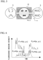
- Fig. 1 shows an analysis device according to a first aspect of the present invention.
- the analysis device includes a light source 1; a light irradiation region 3 irradiated with light from the light source 1; a light-receiving unit 7 configured to receive scattered light (including Raman scattering), transmitted light, fluorescence, or electromagnetic waves from an observed object 5 located in the light irradiation region 3 and convert the received light or electromagnetic waves into an electrical signal; a storage unit 9 configured to receive and record the electrical signal from the light-receiving unit 7; an analysis unit 11 configured to analyze the electrical signal related to the scattered light, the transmitted light, the fluorescence, or the electromagnetic waves recorded by the storage unit 9 and record an analysis result; and an optical system control unit 13 configured to optimize the light irradiation region 3 using machine learning or the like on the basis of the analysis result.
- the analysis device preferably further includes a light-receiving system control unit 27 configured to receive the electrical signal from the light-receiving unit 7 and optimize a light-receiving region 25 which is a region where light is radiated to the light-receiving unit 7.
- the light-receiving system control unit 27 optimizes the light-receiving region 25 using machine learning. Also, the analysis device can rapidly and accurately perform analysis even when the optical system control unit 13 is not present and only the light-receiving system control unit 27 is provided.
- Such an analysis device includes the light source 1; the light irradiation region 3 irradiated with light from the light source 1; the light-receiving unit 7 configured to receive scattered light, transmitted light, fluorescence, or electromagnetic waves from the observed object 5 located in the light irradiation region 3 and convert the received light or electromagnetic waves into an electrical signal; the storage unit 9 configured to receive and record the electrical signal from the light-receiving unit 7; the analysis unit 11 configured to analyze the electrical signal related to the scattered light, the transmitted light, the fluorescence, or the electromagnetic waves recorded by the storage unit 9 and record an analysis result; and the optical system control unit 27 configured to receive the electrical signal from the light-receiving unit 7 and to optimize the light-receiving region 25 which is a region where light is radiated to the light-receiving unit 7.
- a main false positive result indicates a single cell, a plurality of cells, incorporated foreign matter, or the like.
- the present invention can assign additional spatial information to existing flow cytometry information and reduce the false positive rate. Also, generation of a representative template image in the same classification is useful for practical use because it is possible to confirm whether or not classification based on the machine learning conforms to a user's intention.
- machine learning can be applied not only to the integration of flow cytometry technology and high-speed imaging technology such as GMI, but also to the integration of flow cytometry technology and nonlinear molecular spectroscopy technology (Raman spectroscopy, stimulated Raman scattering spectroscopy, or coherent anti-Stokes Raman scattering spectroscopy).
- machine learning of a temporal signal of a scattered spectrum other than an image or a temporal waveform is performed, an analysis time is significantly shortened without involving a Fourier transform, and classification is performed without a human knowledge bias.
- the optical imaging method By optimizing the optical imaging method in accordance with the observed object, it is possible to accurately collect object information while effectively compressing the object information and it is possible to speed up optical imaging and information processing without reducing the accuracy of cytometry. Also, by applying the cytometry result (including human recognition of whether specific information of the observed object is desired or the like) to the optical imaging method, it is possible to make a modification suitable for the purpose and increase the sensitivity of the cytometry.
- the light source 1 and the light irradiation region 3 irradiated with the light from the light source 1 form an optical system for irradiating the observed object with light.
- the optical system may appropriately include an optical element including a mirror or a lens (not shown), a spatial light modulator, and a filter.
- the optical system may be an optical system (a system) having a structured illumination pattern having a plurality of regions with different optical characteristics.
- An example of the optical system may be a group of optical elements having a light source and a filter for receiving the light from the light source and forming a structured illumination pattern.
- Another example of the optical system is a light source group (or a light source group and an optical element group including optical elements) having a plurality of light sources for configuring an illumination pattern.
- the light source may be white light or monochromatic light.
- optical characteristics are characteristics related to one or more of an intensity of light, a wavelength of light, and polarization (e.g., transmittance), the present invention is not limited thereto.
- An example of a structured illumination pattern having a plurality of regions having different optical characteristics includes a plurality of regions having a first intensity of light and a plurality of regions having a second intensity of light. Examples of the plurality of regions having different optical characteristics have portions with different optical characteristics randomly scattered in a certain region.
- the storage unit is an element connected to an element such as a light-receiving unit to exchange information with the connected element and configured to record the information.
- the light-receiving unit includes a storage device such as a memory or a hard disk, they function as a storage unit.
- a server or the like connected to the computer functions as a storage unit in addition to the storage device (a memory, a hard disk, or the like) of the computer.
- the storage unit receives an electrical signal from the light-receiving unit 7 and records the received electrical signal.
- a class in which a distance between an electrical signal pattern serving as a template of each class obtained in advance and a newly obtained electrical signal pattern is minimized is designated as a class of a newly obtained electrical signal pattern.
- electrical signals to be observed are stored, and a pattern group of stored electrical signals is classified.
- classification is performed so that each electrical signal pattern from an average electrical signal pattern of each class is minimized.
- a new electrical signal pattern is classified on the basis of this stored data and classification data.
- the stored data and classification data are updated on the basis of a new electrical signal pattern. Updating the classification data indicates that a new electrical signal pattern is used to calculate average data and intermediate value data of each class. For example, the classification data is updated by adding a new electrical signal pattern c to (a+b)/2 which is an average value of electrical signal patterns a and b and obtaining (a+b+c)/3.
- the analysis unit may include, for example, a temporal signal information acquisition unit configured to receive an optical signal during a fixed period and acquire temporal signal information of the optical signal and a partial signal separation unit configured to separate partial temporal signal information in a partial region of an observed object from the temporal signal information. For example, if temporal signal information when the observed object is a contaminant which is not a cell or the like is stored and partial temporal signal information of a certain observation part is classified as a pattern classified as partial temporal signal information of a contaminant or the like which is not a cell, it is possible to ascertain that there is no cell in the observation part.
- the partial signal separation unit is an element for separating the partial temporal signal information in the partial region of the observed object from the temporal signal information.
- the temporal signal information includes a detected signal derived from each part of the observed object.
- the partial signal separation unit separates partial temporal signal information which is temporal signal information in each partial region of the observed object from the temporal signal information.
- the partial signal separation unit reads information H about the stored illumination pattern and separates the partial temporal signal information using the information H about the read illumination pattern and the temporal signal information. That is, because there is a change corresponding to the information H about the illumination pattern, the temporal signal information can be separated into the partial temporal signal information using the information H about the illumination pattern.
- the image reconstruction unit is an element for reconstructing an image related to an observed object using images of parts of the observed object reconstructed by the partial image reconstruction unit. Because the image of each part of the observed object is an image of each region of the observed object, the image related to the observed object can be reconstructed by adjusting the image.
- the analysis device optimizes a classification algorithm of the analysis unit 11 using machine learning. That is, the analysis unit 11 includes a classification algorithm for performing various types of analysis. This classification algorithm is optimized using machine learning.
- the classification algorithm includes an algorithm for making a classification using the classification of the observed object described above or the classification of a signal when the observed object is not present.
- An example of the analysis is a process of ascertaining a characteristic optical signal component of the observed object, setting a threshold value to be used in a classification operation, or setting a condition for optimizing the optical system and the detection system.
- the machine learning is well-known as disclosed in, for example, Japanese Patent No. 5574407 , Japanese Patent No. 5464244 , and Japanese Patent No. 5418386 .
- An example of the machine learning is learning using an Ada Boosting algorithm.
- the machine learning is a process of obtaining optical signals of a plurality of objects among observed objects and learning characteristics of the observed object from the obtained optical signals. By performing machine learning, it becomes possible to detect the presence or absence of specific cells extremely efficiently and rapidly.
- the object of the machine learning is not limited to an image, for example, it being only necessary to detect a vibration that is not imaged as in a case in which Raman spectroscopy is used and to use a detected signal for an analysis object.
- the analysis unit can analyze optical signals of a plurality of observed objects using the machine learning of and perform analysis such as the classification/recognition of the optical signals of the observed objects.
- the analysis unit 11 analyzes an observed object without reconstructing an image of the observed object with an electrical signal related to scattered light, transmitted light, fluorescence or electromagnetic waves.
- the analysis unit 11 analyzes the observed object using the above-described temporal signal information, partial temporal signal information, or GMI.
- the optical system control unit 13 is an element for optimizing the light source 1 or the light irradiation region 3 on the basis of an analysis result.
- a control signal (a control command) for controlling the light-receiving unit 7, the light source 1, or the optical element constituting the optical system may be requested in the analysis unit described above, or may be requested in the optical system control unit 13. If the control command is requested in the analysis unit, the optical system control unit 13 can optimize a light source system by controlling the light source 1 or the optical element constituting the optical system in accordance with the control signal (the control command) requested by the analysis unit 3.
- optical system control unit 13 is a computer connected so that information can be exchanged with a control unit configured to control the light-receiving unit 7, the light source 1, or the optical element constituting the optical system.
- a program is installed so that a specific arithmetic process and an input/output can be performed.
- An example of this program is a program for performing machine learning.
- the optical system control unit 13 perform processing with the temporal waveform electrical signal (GMI) as it is without reconstructing the image of the observed object on the basis of the electrical signal from the light-receiving unit 7.
- GMI temporal waveform electrical signal
- a function of reconstructing the image of the observed object may be provided. In this case, the image quality can be verified.
- the optical system control unit 13 process the temporal waveform electrical signal as it is without performing a Fourier transform on the spectrum and analyzing a molecular spectrum in the frequency domain on the basis of the electrical signal from the light-receiving unit 7.
- the optical system control unit 13 may analyze the molecular spectrum in the frequency domain by performing a Fourier transform on an electromagnetic wave spectrum.
- the optical system control unit 13 optimizes the light source 1 or the light irradiation region 3 using machine learning.
- An example of optimization of the light source 1 is to adjust an intensity of light of the light source 1.
- the light from the light source 1 has a plurality of light regions 21, and the optical system control unit 13 controls an optical structure of the plurality of light regions 21.
- the optical system control unit 13 analyzes a region of presence of the observed object 5 on the basis of the electrical signal and performs control for limiting the light irradiation region 3.
- the optical system control unit 13 analyzes a density of the observed object 5 on the basis of the electrical signal to obtain coarseness/fineness information of the observed object and controls the light source 1 or the light irradiation region 3 on the basis of the coarseness/fineness information.
- the analysis device preferably further includes the light-receiving system control unit 27 configured to receive an electrical signal from the light-receiving unit 7 and optimize the light-receiving region 25 which is a region where light is radiated to the light-receiving unit 7.
- the analysis unit described above may perform analysis of the light-receiving system. That is, for example, the analysis unit adopts a program for machine learning, and classifies a received optical signal of part of the light-receiving unit where no useful information is obtained. If the received optical signal of a certain part of the light-receiving unit is classified as this classification, for example, processing is performed so that information from this part is not used for analysis.
- the light-receiving system control unit 27 optimizes the light-receiving region 25 using machine learning.
- the light source 1 or the light-receiving region 25 may be optimized using a technique similar to optimization of the optical system by the optical system control unit 13.
- An example of the light-receiving system control unit 25 is a computer connected so that information can be exchanged with the control device configured to control the light-receiving unit 7, the light source 1, or the optical elements constituting the light-receiving system and the light-receiving region 25. That is, the present description discloses optimization of the optical system and optimization of the light-receiving system and discloses optimization of only the light-receiving system.
- the analysis device may include various types of element in a well-known analysis device.
- An example of such an element is a relative position control mechanism.
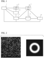
- Fig. 5 is a conceptual diagram showing that the observed object passes through patterned illumination.
- the observed object 5 is moved by a relative position control mechanism and passes through patterned illumination of the optical system.
- This patterned illumination optical structure exhibits its intensity distribution in a matrix of H(x, y).
- This observed object 5 has fluorescence molecules indicated by optical spatial information, for example, F 1 to F 4 . These fluorescence molecules do not emit fluorescence according to an intensity of received light or an intensity of emitted fluorescence varies. That is, in this example, the fluorescence molecule denoted by F 2 first emits fluorescence and an intensity of emitted fluorescence is affected by the patterned illumination through which the observed object 5 passes.
- the light from the observed object 5 may be appropriately focused according to a lens or the like. Then, the light from the observed object 5 is transmitted to one or a few pixel detection elements.
- a traveling direction of the observed object is set as an x-axis, and a y-axis is provided in a direction perpendicular to the x-axis which is in the same plane as that of the x-axis.
- F 1 and F 2 are observed as fluorescence on y 1 which is the same y coordinate (F 1 and F 2 are denoted by H(x, y 1 ).
- F 3 and F 4 are observed as fluorescence on y 2 which is the same y coordinate (F 3 and F 4 are denoted by H(x, y 2 )).
- Fig. 6 is a conceptual diagram showing a state of fluorescence emitted by the observed object shown in Fig. 5 .
- the fluorescence is emitted from each fluorescence molecule.
- F 1 and F 2 experience the same illumination pattern, they are considered to have similar time response patterns or output patterns.
- the intensity of emitted light is considered to be different between F 1 and F 2 .
- intensities of emitted light of F 1 and F 2 can be approximated so that they are products of F 1 and F 2 which are coefficients specific to each light emitting molecule and H(x, y 1 ) which is a time response pattern common to the coordinate y 1 .
- F 3 and F 4 is a conceptual diagram showing a state of fluorescence emitted by the observed object shown in Fig. 5 .
- the fluorescence is emitted from each fluorescence molecule.
- the intensity of emitted light is considered to be different between F 1 and F 2 .
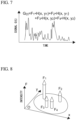
- Fig. 7 is a conceptual diagram showing a detected signal when fluorescence emitted by the observed object shown in Fig. 5 is detected.
- This detected signal is observed as a sum signal of fluorescence signals shown in Fig. 6 .
- this signal includes a time-varying pattern H(x, y n ) of a plurality of intensities.
- H(x, y n ) a time-varying pattern of fluorescence signals
- Fig. 8 is a conceptual diagram showing a position and an intensity of fluorescence of fluorescence molecules obtained from an intensity of a detected signal. As shown in Fig. 8 , fluorescence coefficients (intensities of fluorescence) F 1 to F 4 can be obtained from the detected signal G(t).
- Fig. 9 is a diagram showing the principle of image reconstruction.
- F(1) and F(2) are assumed to be in-object coordinates.
- light of a first pattern is radiated to F(1) and is not radiated to F(2).
- light of a second pattern is irradiated to F(1) and light of the first pattern is radiated to F(2).
- no light is radiated to F(1) and the light of the second pattern is radiated to F(2).
- the detected signal G(t) is as follows.
- F(1) and F(2) can be analyzed. Using this principle, the coordinates F(1) to F(n) can be obtained by performing analysis in a similar manner even if there are more in-object coordinates.
- Fig. 10 is a diagram showing an example of the image reconstruction process.
- the image is represented as f (an object position information vector) in a matrix equation.
- patterned illumination is represented by H(X, y)
- X is represented by a variable which varies with time.
- an intensity of a detected signal is represented as g (a measured signal vector).
- g a measured signal vector.
- H it only necessary to multiply an inverse matrix H -1 of H from the left in order to obtain f.
- H may be too large to easily obtain the inverse matrix H -1 of H.
- a transposed matrix H t of H may be used instead of an inverse matrix. Using this relationship, it is possible to obtain an initial estimated value f int off. Thereafter, by optimizing f with the initial estimated value f int off, the image of the observed object can be reconstructed.
- Fig. 10 is a diagram showing an example of the image reconstruction process.
- the image is represented as f (an object position information vector) in a matrix equation.
- the patterned illumination is represented as H(X, y), and X is represented by a variable which varies with time.
- an intensity of a detected signal is represented as g (a measured signal vector).
- H it only necessary to multiply the inverse matrix H -1 of H from the left in order to obtain f.
- H may be too large to easily obtain the inverse matrix H -1 of H.
- an initial estimated value f init off can be obtained as a result of multiplying a transposed matrix H T of H by g. Thereafter, it is possible to reconstruct the image of the observed object by optimizing f with the initial estimated value f init off.
- Shape of optical structure adjusted to shape of observed object
- the overall shape of the optical structure need not be rectangular. For example, bright parts at the four corners of an optical structure are changed to dark parts and the dark parts enlarged to an extent at which the quality does not deteriorate. If the quality drops, it is only necessary to repeat a cycle in which a few new points are added to the four corners.
- a dense structure of cytoplasm, nuclei, or the like and a sparse structure of a cell membrane, localized molecules, or a specific chromosome label exist.
- a sparse optical structure is desirable for a dense object structure, and it is desirable to design a dense optical structure for a sparse object structure.
- the density of the object is recognized on the basis of the GMI electrical signal.
- the object when a ratio of a value of an object signal integrated over time to a product of a maximum value of the object signal and a time width of the object signal (a product of a value of the object signal integrated over time/a maximum value of the object signal and a time width of the object signal) is greater than or equal to a fixed value, the object is dense. Also, when the ratio is less than or equal to the fixed value, the object is sparse. This value is adjusted according to a sample or an object structure.
- a more sparse or dense optical structure is designed. For example, the occupancy of a random bright part relative to the whole structure is increased or decreased and a new random pattern is created (the current GMI optical structure uses a DMD/optical mask and the structure is simply random; thus, two values of brightness and darkness are present and a bright part is specified as any % of the whole and randomly scattered).
- the above-described cycle is repeated until the above-described ratio (the ratio of the value of the object signal integrated over time to the product of the maximum value of the object signal and the time width of the object signal) falls in a certain fixed range (depending upon the object).
- an intensity of an optical signal is very weak and an S/N ratio is low. If the S/N ratio is low, highly accurate cell information processing and cytometry may not be able to performed.
- One technique for increasing the S/N ratio in GMI is to perform a plurality of binning operations on pixels in a spatial light modulator and set the pixels subjected to the binning operations as unit pixels of the GMI optical structure. Thereby, an intensity of light of the unit pixel of the GMI optical structure can be increased and the S/N can be improved.
- one technique for increasing the S/N ratio is to reduce light radiation to a part which does not pass through the object. Thereby, the intensity of noise light can be reduced and S/N can be improved.
- a complex structure such as a cytoskeletal structure, a virus infection path, or a cell signal network is provided. It is difficult to design an optimum optical structure for such a complex structure.
- the optical structure can be automatically optimized using machine learning, for example, for the purpose of improving the quality of the reconstructed image.
- optimization including the above-described example can be achieved, for example, by setting an objective function to improvement of the imaging throughput, reduction of an amount of calculation for the electrical signal, reduction of an amount of image information, improvement of the image quality, improvement of sensitivity to a target feature quantity (a nucleus/cytoplasm ratio, a cell size, a chromosome aggregation image, the number of chromosomes, or the like), improvement of S/N of a signal, improvement of recognition accuracy, or the like.
- a target feature quantity a nucleus/cytoplasm ratio, a cell size, a chromosome aggregation image, the number of chromosomes, or the like
- the optical structure can be optimized with a well-known machine learning and optimization algorithm.
- Well-known machine learning and optimization algorithms include evolutionary algorithms and simulated annealing.
- it is possible to achieve the above-described objective and optimize an optical structure using machine learning by setting minimization of an area of the illumination region, maximization of image quality or recognition accuracy, maximization of S/N, or the like as an objective function of the optimization algorithm.
- the optical system control unit appropriately changes the illumination pattern and obtains the comparison value again using the same observed object as the previous observed object 5 or using the same type of observed object. In this manner, after a plurality of combinations of illumination patterns and comparison values are obtained, it is only necessary to determine an optimum illumination pattern in consideration of an amount of information of the illumination pattern.
- the size of the observed object is first ascertained on the basis of the above-described method, and the size of the irradiation pattern is adjusted. Thereafter, the pattern itself in the illumination pattern across the adjusted size (region) is changed to obtain the comparison value ( ⁇ ) in a plurality of patterns. Moreover, it is only necessary to obtain an optimum illumination pattern by comparing with the comparison value ( ⁇ ).
- the comparison value ( ⁇ ) may be the sum of squares of the difference values of the pixels.
- the detection system images an observed object and obtains a captured image. Then, image analysis is performed on the captured image, and a composition or tissue of each part is ascertained. Then, light information corresponding to each composition or tissue is obtained from a table storing information about light (e.g., fluorescence) emitted from each composition and tissue when light irradiation is performed or the like. In this manner, it is possible to ascertain a type of light response when light is radiated to the observed object. Then, it is possible to estimate the optical signal g on the basis of the captured image. This is the estimated signal g C estimated by the estimated signal calculation unit.
- the optical signal g is, for example, a spectrum as shown in Fig. 7 .
- ⁇ may be a sum of differences between the relative intensities of the estimated signal g C and the optical signal g per unit time (or an absolute value of a difference or a square of the difference).
- the estimated signal g C and the optical signal g may be converted into a new coordinate domain to achieve a difference in a relative intensity or the like in the domain. It is only necessary to obtain the evaluation value ( ⁇ ) on the basis of various illumination patterns and optimize the illumination pattern using the evaluation value ( ⁇ ).
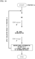
- Fig. 14 is a conceptual diagram showing an example of a process of optimizing the illumination pattern.
- This example is used, for example, when information about an observed object (for example, a pattern of an image obtained by reconstructing the observed object in an image reconstruction unit) has already been stored. That is, this example further includes a control unit configured to change the illumination pattern using an image (F) of the observed object reconstructed by the image reconstruction unit.
- the control unit performs pattern authentication with the image (F) of the reconstructed observed object and a pattern of the image stored in advance. Because the pattern authentication technology is well-known, pattern authentication can be implemented by installing a well-known pattern authentication program in a computer.
- This example can be effectively used, for example, when an object (an accepted item or a rejected item) is selected or when inspecting for the presence or absence of an object. Also, this example can be used for the purpose of automatically measuring the number of cells contained in a specific region. That is, a preferred example of the imaging device further includes an observed object determination unit configured to classify an observed object using the image of the observed object reconstructed by the image reconstruction unit.
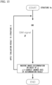
- Fig. 15 is a conceptual diagram showing an example of a process of optimizing the illumination pattern.
- This example is used, for example, when information about the observed object (for example, the pattern of the optical signal g) has already been stored.
- This example further includes a control unit configured to change the illumination pattern using the optical signal g detected by one or a few pixel detection elements.
- the control unit performs pattern authentication with a pattern of the optical signal g detected by one or a small number of pixel detection elements and the optical signal g stored in advance. Because the pattern authentication technology is well-known, pattern authentication can be implemented by installing a well-known pattern authentication program in a computer. Alternatively, for example, the two signals g may be converted into a new coordinate domain to achieve a difference in a relative intensity or the like within the domain.
- a preferred example of the imaging device further includes a reconstructed image classification unit configured to classify the reconstructed image of the observed object using a plurality of images of the observed object reconstructed by the image reconstruction unit.
- the image (F) classified by the reconstructed image classification unit is used by the control unit or/and the determination unit.
- a preferred usage form of this analysis device is a flow cytometer having any one of the above-described analysis devices.
- This flow cytometer has a flow cell including the light irradiation region 3.
- the flow cytometer preferably includes a sorting unit configured to recognize an observed object on the basis of an analysis result of the analysis unit 11 and sort the observed object 5. More specifically, when the observed object 5 is a target object and when the observed object 5 is not a target object, the target object can be sorted by making a path after passing through the sorting unit different.
- the target object may be analyzed in advance and information indicating the target object (a threshold value or the like) may be stored in the storage unit. Also, an object including a large number of target objects may be observed, the classification unit may recognize the object as the observed object, and classification information about the target object may be subjected to a machine learning algorithm. This classification information is, for example, a characteristic peak included in various spectra.
- the light-receiving unit receives an optical signal from the observed object.
- the analysis unit analyzes the optical signal.
- the analysis unit reads the classification information of the target object stored in the storage unit and determines whether the observed observed object is a target object by comparing the classification information with the optical signal. If the analysis unit determines that the observed observed object is the target object, the analysis unit sends a control signal corresponding to the observed object serving as the target object to the classification unit.
- the classification unit receiving the control signal adjusts the path and guides the observed object to the path of the target object. In this manner, it is possible to recognize the target object and an object other than the target object and classify the objects.
- Example 1-1 (Supervised machine learning, decompression/conversion of image into temporal signal using optical structure, classifier formation, and classification)
- a computer used in present example included a 2.8 GHz Intel Core i7 processor and 16 GB of memory.
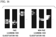
- a total of 1100 images including 1000 images for learning and 100 images for classification accuracy measurement were provided for a face image group and a non-face image group in which an image had 19 pixels in length and 19 pixels in width (an image source of Fig. 16 is the Center for Biological and Computational Learning at MIT).
- the optical structure was a patterned illumination optical structure or detected optical structure in an experimental system
- the optical structure used here was 19 pixels in width and 343 pixels in length ( Fig. 17 )
- the temporal signal was generated for (1x192) pixels (which are the same as those of the original image).
- a face or non-face label was attached to all waveform signals, and a classifier was formed by learning 1000 waveforms for learning using a linear classification type support vector machine technique.
- a temporal signal was provided using the same optical structure on the basis of 100 new face and non-face images.
- the label was removed from this sample, the formed classifier performed automatic classification, and a correct answer rate of the label (face or non-face) was measured.
- learning 1000 images for learning using a support vector machine technique 100 new face and non-face images were similarly provided.
- the label was removed from this sample, the formed classifier performed automatic classification, and a correct answer rate of the label (face or non-face) was measured.
- the classification accuracy for a face or non-face temporal signal (the number of correct answers for face and non-face/total number ⁇ 100) in the classifier learning the temporal signal sample was 87% and the classification accuracy for the face or non-face of the image in the classifier performing learning was 82%. According to this result, it was found that, even if a temporal signal generated by passing an image through the optical structure was learned and classified, it was possible to obtain a classification result at least equivalent to that of learning and classifying the original image.
- Example 1-2> Supervised machine learning, compression/conversion of image into temporal signal using optical structure, classifier formation, and classification
- a computer used in the present example included a 2.8 GHz Intel Core i7 processor and 16 GB of memory.
- a total of 1100 images including 1000 images for learning and 100 images for classification accuracy measurement were provided for a face image group and a non-face image group in which an image has 19 pixels in length and 19 pixels in width ( Fig. 16 ).
- the optical structure was a patterned illumination optical structure or a detection optical structure in the experimental system, and the optical structure used here had 19 pixels in width and 50 pixels in length ( Fig. 18 ), and the temporal signal was generated in 68 pixels and 81% of a total number of original image pixels were compressed.
- a face or non-face label was attached to all compressed temporal signals and a classifier was formed by learning 1000 waveforms for learning using the support vector machine technique.
- a compressed temporal signal was provided using a similar optical structure on the basis of 100 new face and non-face images.
- the label was removed from this sample, the formed classifier performed automatic classification, and a correct answer rate of the label (face or non-face) was measured.
- learning 1000 images for learning using a linear classification type support vector machine technique 100 new face and non-face images were similarly provided.
- the label was removed from this sample, the formed classifier performed automatic classification, and a correct answer rate of the label (face or non-face) was measured.
- the classification accuracy for a compressed temporal waveform signal of the face or non-face (the number of correct answers for face and non-face/total number ⁇ 100) in the classifier learning the compressed temporal waveform signal sample was 75% and the classification accuracy for the face or non-face of the image in the classifier learning the image sample was 82%. According to this result, it was found that the classification accuracy using machine learning can also maintain equivalent accuracy according to optical image compression through the optical structure.
- a computer used in this embodiment included a 2.8 GHz Intel Core i7 processor and 16 GB of memory.
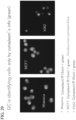
- viable cell staining was performed using calcein AM for a single-cell group generated by dispersing mouse spleen.
- a fluorescence-labeled single cell solution as described above was spread on a glass slide and a large number of fluorescence images of a single-cell group were captured by an sCMOS camera (Flash 4.0 manufactured by Hamamatsu Photonics K.K.) using a fluorescence microscope.
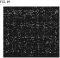
- This image data was read within the computer, the position of a single cell was specified by software (imagej), and a single-cell periphery was partitioned using 70 pixels in length and width to cut out 2165 samples of a large number of single-cell image group samples ( Fig. 19 ).
- This single-cell image group included images containing single cells having different sizes and images including a plurality of cells or objects other than cells.
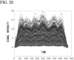
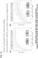
- a temporal signal e.g., a GMI waveform
- a temporal waveform group of virtual flow cytometry cells was provided ( Fig. 20 ).
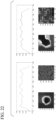
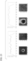
- the optical structure used here had 70 pixels in length and 400 pixels in width, and the temporal signal had 470 pixels ( Fig. 21 ).
- Single-cell temporal waveform samples provided as described above were classified using unsupervised machine learning classification using software (matlab). Specifically, the single-cell temporal waveform samples were classified into 20 types of cell groups using a k-means technique. A representative (average) temporal signal was generated from the cell temporal waveform group included in each same classification group and a cell image was generated on the basis of this temporal signal ( Figs. 22 and 23 ). As a result, it is can be seen that single cells, a plurality of cells, waste, a cell size, or the like are correctly classified. These are one of the greatest error sources in conventional cytometry and it was showed that correct classification is also made in unsupervised machine learning using a compressed temporal waveform signal through an optical structure.
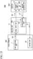
- Fig. 25 shows an example of an analysis system 200.
- the analysis system 200 includes a flow cytometer 300, the analysis unit 11, and a computer 400.
- the flow cytometer 300 observes and sorts the observed object 5.
- the flow cytometer 300 outputs an optical signal related to the observed object 5 to the analysis unit 11.
- the analysis unit 11 classifies the observed object 5 from the flow cytometer 300 on the basis of an optical signal related to the observed object 5.
- the computer 400 mechanically learns the optical signal related to the observed object 5 observed by the flow cytometer 300.
- the computer 400 changes a classification algorithm of the classification unit 101 on the basis of a machine learning result.
- the flow cytometer 300 includes a light-receiving unit 7 and a sorting unit 33.
- the computer 400 includes a storage unit 9 and a machine learning unit 401.
- the storage unit 9 stores an input signal SS.
- the machine learning unit 401 performs machine learning on the optical signal stored in the storage unit 9.
- the machine learning unit 401 changes the classification algorithm of the classification unit 101 included in the analysis unit 11 on the basis of the machine learning result.
- the machine learning unit 401 changes the logic circuit configuration of the classification unit 101 on the basis of the machine learning result.
- the machine learning unit 401 configures a classification logic LP, which is a logic circuit configuration of a classification algorithm suitable for the observed object 5, on the basis of the machine learning result, and changes the logic circuit.
- the signal input unit 100 acquires the electrical signal ES from the light-receiving unit 7.
- the signal input unit 100 outputs the electrical signal ES acquired from the light-receiving unit 7 as an input signal SS to the storage unit 9 and the classification unit 101.
- the signal input unit 100 may remove noise of the electrical signal ES by applying a filter to the electrical signal ES.
- the noise is, for example, high-frequency noise, shot noise, and the like.
- the signal input unit 100 can stabilize a trigger position at which the electrical signal ES starts to be acquired as the input signal SS.
- the signal input unit 100 can output a signal suitable for machine learning as the input signal SS by stabilizing the trigger position.
- the signal input unit 100 may distinguish whether the observed object 5 is a single cell or a plurality of cells and whether the observed object 5 is waste and distinguish a cell size of the observed object 5 and the like, and determine whether or not to output the signal as the input signal SS.
- the above-described filter is changed in accordance with the observed object 5.
- the filter removes noise by making the electrical signal ES have a gentle waveform.
- the filter is a filter for performing comparison with the threshold value of the electrical signal ES, a filter for performing a moving average operation on the electrical signal ES and comparing a value obtained through the moving average operation with a threshold value, a filter for differentiating the value obtained through the moving average operation on the electrical signal ES and comparing the differentiated value with a threshold value, or the like.
- the classification unit 101 acquires the input signal SS from the signal input unit 100.
- the classification unit 101 classifies the observed object 5 observed by the flow cytometer 300 on the basis of the input signal SS acquired from the signal input unit 100.
- the classification unit 101 classifies the input signal SS through the logic circuit, thereby determining the observed object 5. By classifying the observed object 5 through the logic circuit, the classification unit 101 can classify the observed object 5 at a higher speed than in a general-purpose computer.
- the light-receiving unit 7 receives scattered light, transmitted light, fluorescence, or electromagnetic waves from the observed object located in the light irradiation region irradiated with the light from the light source, and converts the received light or electromagnetic waves into an electrical signal.
- the analysis unit 11 analyzes the observed object 5 on the basis of a signal extracted on the basis of a time axis of the electrical signal ES output from the light-receiving unit 7.
- the analysis unit 11 includes the signal input unit 100.
- the signal input unit 100 filters the electrical signal ES output by the flow cytometer 300.
- the signal input unit 100 filters the electrical signal ES to output a signal with reduced noise as the input signal SS to the classification unit 101 and the storage unit 9.
- the machine learning unit 401 can perform machine learning on the basis of the input signal SS with reduced noise and can improve the accuracy of classification of the observed object 5.
- the signal input unit 100 may include a logic circuit. When the signal input unit 100 includes a logic circuit, the filter configuration may be changed on the basis of the machine learning result.
- the analysis unit 11 includes the classification unit 101. Because the classification unit 101 includes the logic circuit, the classification unit 101 can classify the observed object 5 in a shorter time than in computation with a general-purpose computer.
- Fig. 26 is a diagram showing an example of a discriminant calculation circuit of the analysis unit 11.
- Equation (1) is a constant.
- b included in Equation (1) is changed so that the classification condition becomes strict, a false positive rate can be minimized.
- a and Y included in Equation (1) are values obtained using machine learning.
- Equation (1) an element included in Equation (1) in which X is marked with a ⁇ (hat symbol) thereabove will be described as X(hat).
- Equation (2) is a matrix obtained using machine learning.
- x included in Equation (3) is data input to the analysis unit 11.
- the data input to the analysis unit 11 is a signal extracted on the basis of the time axis of the electrical signal output from the light-receiving unit 7.
- An element included in Equation (3) in which x is marked with ⁇ (hat symbol) thereabove will be described as x(hat).
- x(hat) k is a value obtained by normalizing x.
- Equation (1) is implemented as a logic circuit
- the logic circuit scale becomes enormous and may not fit an FPGA or PLD logic circuit size. Therefore, a logic circuit based on Equation (4) is mounted on the logic circuit mounted on the classification unit 101.
- f x b + ⁇ j N SV ⁇ j exp K ⁇ ⁇ k N SL X ⁇ jk ⁇ x k ⁇ ⁇ k 2
- Equation (4) An element included in Equation (4) in which K is marked with ⁇ (tilde symbol) thereabove will be described as K(tilde).
- An element included in Equation (4) in which ⁇ is marked with ⁇ (tilde symbol) thereabove will be described as ⁇ (tilde).
- Equation (4) ⁇ j , K(tilde), X(tilde) jk and ⁇ (tilde) k included in Equation (4) can be represented by Equations (5).
- the machine learning unit 401 provided in the computer 400 calculates Equations (5) in advance. A calculation result is incorporated in the logic circuit included in the analysis unit 11.
- b and K(tilde) included in Equation (4) are constants, ⁇ j and ⁇ (tilde) k are vectors, and X(tilde) jk is a matrix. [Math.
- X ⁇ jk X ⁇ jk + ⁇ k ⁇ k
- ⁇ ⁇ k 1 ⁇ k
- Fig. 26(b) shows a discriminant calculation circuit for calculating the above-described Equation (4) at a higher speed.
- the discriminant calculation circuit shown in Fig. 26(b) in addition to the configuration in which the above-described addition of k is subjected to parallel processing, the addition of j included in Equation (4) is subjected to parallel processing for calculation.
- the analysis unit 11 can classify the observed object 5 at a higher speed than in the discriminant calculation circuit shown in Fig. 26(a) .
- Fig . 28 shows a concept thereof.
- a time required for image reconstruction and feature quantity extraction and analysis from the image is shortened by directly applying machine learning to the temporal waveform signal and a processing speed is significantly shortened by analyzing compressed small data as it is.
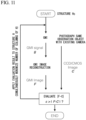
- Fig. 31 different cell types (here, MCF7 and Miapaca) shown in Fig. 31 are experimentally mixed, cell classification is performed on the temporal waveform signal generated according to GMI using a previously provided classifier, and verification of the classification result is performed according to a total of DAPI signal intensities.
- Fig. 32 shows a result thereof.
- a concentration of MCF7 using machine learning classification for a temporal waveform of a green fluorescence signal is shown with respect to a concentration of MCF7 according to DAPI (blue, correct answer) classification when the concentration of MCF7 in a mixed liquor is changed and a correct answer is shown with high accuracy (>87%).
- DAPI blue, correct answer
- MCF7 and Miapaca are compared in a green fluorescence image, it is difficult to perform classification with the human eye and the usefulness of machine learning is obvious. High-speed and high-accuracy cell classification implementation has been demonstrated.
- Figs. 33 to 35 show an example in which a fluid system is implemented in flow cytometry implementation.
- a fluid system is implemented in flow cytometry implementation.
- the above-described cell classification accuracy when the fluid experimental system is changed was verified, no correct answer was given according to an intensity of a DAPI signal and a temporal waveform group with a cell type label was incorporated into the computer and was classified (without teaching the correct answer to the machine) and accuracy was verified.
- Fig. 33 it is generally known that it is possible to align cells at the same width (fluctuation) on the same stream line using microfluidic engineering (a flow focusing method).
- the flow path width control unit provided in the analysis device may control the flow path width so that the flow path width becomes the first flow path width which is the width based on the diameter of the observed object and has a narrower width than the second flow path width
- the teach information generation unit may further generate the first teacher information based on the first observed result signal detected by the detection unit in the first flow path width controlled by the flow path width control unit
- the estimation unit may estimate the state of the observed object which moves along the flow path on the basis of the first teacher information generated by the teacher information generation unit, the second teacher information generated by the teacher information generation unit, and the observed result signal acquired by the acquisition unit.
Landscapes
- Engineering & Computer Science (AREA)
- Chemical & Material Sciences (AREA)
- Health & Medical Sciences (AREA)
- Physics & Mathematics (AREA)
- Life Sciences & Earth Sciences (AREA)
- General Physics & Mathematics (AREA)
- General Health & Medical Sciences (AREA)
- Analytical Chemistry (AREA)
- Biochemistry (AREA)
- Immunology (AREA)
- Pathology (AREA)
- Theoretical Computer Science (AREA)
- Dispersion Chemistry (AREA)
- Evolutionary Computation (AREA)
- Bioinformatics & Cheminformatics (AREA)
- Computer Vision & Pattern Recognition (AREA)
- Artificial Intelligence (AREA)
- Multimedia (AREA)
- Data Mining & Analysis (AREA)
- Databases & Information Systems (AREA)
- General Engineering & Computer Science (AREA)
- Computing Systems (AREA)
- Medical Informatics (AREA)
- Software Systems (AREA)
- Nuclear Medicine, Radiotherapy & Molecular Imaging (AREA)
- Organic Chemistry (AREA)
- Zoology (AREA)
- Wood Science & Technology (AREA)
- Biotechnology (AREA)
- Biomedical Technology (AREA)
- Bioinformatics & Computational Biology (AREA)
- Evolutionary Biology (AREA)
- Mathematical Physics (AREA)
- Spectroscopy & Molecular Physics (AREA)
- Signal Processing (AREA)
- Genetics & Genomics (AREA)
- Sustainable Development (AREA)
- Microbiology (AREA)
- Medicinal Chemistry (AREA)
- Molecular Biology (AREA)
Claims (12)
- Analysevorrichtung, umfassend:eine Lichtempfangseinheit (7), die ausgelegt ist zum 1) Empfangen von gestreutem Licht, durchgelassenem Licht, Fluoreszenz oder elektromagnetischen Wellen als optische Signale von einem betrachteten Objekt (5), das einen Lichtbestrahlungsbereich (3) durchläuft, der mit dem Licht von einer Lichtquelle (1) bestrahlt wird, wobei die Lichtempfangseinheit (7) ein oder mehrere Pixeldetektionselemente enthält, um die optischen Signale von dem betrachteten Objekt (5) zu empfangen, und 2) Umwandeln der empfangenen Lichter oder elektromagnetischen Wellen in zeitliche elektrische Signale, wobei räumliche Informationen des betrachteten Objekts (5), die in eine eindimensionale zeitliche Wellenform komprimiert sind, in den zeitlichen elektrischen Signalen enthalten sind,dadurch gekennzeichnet, dass die Analysevorrichtung ferner umfasst:eine Analyseeinheit (11), die ausgelegt ist zum 1) Optimieren von einem Klassifizierungsalgorithmus unter Verwendung von maschinellem Lernen und 2) Analysieren des zeitlichen elektrischen Signals, das mit den optischen Signalen von den betrachteten Objekten (5) in Beziehung steht, die von der Lichtempfangseinheit (7) aus den empfangenen Lichtern oder elektromagnetischen Wellen umgewandelt wurden, um die betrachteten Objekte (5) für die Erkennung der Klasse zu analysieren, zu der das betrachtete Objekt (5) gehört, basierend auf der eindimensionalen zeitlichen Wellenform unter Verwendung des Klassifizierungsalgorithmus,wobei die Analyseeinheit (11) dazu ausgelegt ist, das betrachtete Objekt (5) für die Erkennung der Klasse, zu der das betrachtete Objekt (5) gehört, ohne Bildrekonstruktion des betrachteten Objekts (5) zu analysieren.
- Analysevorrichtung nach Anspruch 1, ferner umfassend:
eine Steuereinheit (13) für das optische System, die dazu ausgelegt ist, die Lichtquelle (1) oder den Lichtbestrahlungsbereich (3) auf der Grundlage eines Analyseergebnisses der Analyseeinheit (11) zu optimieren. - Analysevorrichtung nach Anspruch 2,wobei das Licht von der Lichtquelle (1) eine Vielzahl von Lichtbereichen (21) aufweist, undwobei die Optimierung der Lichtquelle (1) oder des Lichtbestrahlungsbereichs (3) durch mindestens eines der Verfahren durchgeführt wird, die ausgewählt sind aus i) Einstellen der Intensität des Lichts der Lichtquelle (1), ii) Optimieren der optischen Struktur der Vielzahl von Lichtbereichen (21), und iii) Begrenzen des Lichtbestrahlungsbereichs (3).
- Analysevorrichtung nach Anspruch 1, wobei der Klassifizierungsalgorithmus unter Verwendung von maschinellem Lernen optimiert wird, einschließlich eines Prozesses, der optische Signale einer Vielzahl von Objekten unter betrachteten Objekten (5) erhält.
- Analysevorrichtung nach einem der Ansprüche 2 bis 4, wobei die Steuereinheit (13) für das optische System dazu ausgelegt ist, die Lichtquelle (1) oder den Lichtbestrahlungsbereich (3) unter Verwendung von maschinellem Lernen zu optimieren.
- Durchflusszytometer (300), umfassend die Analysevorrichtung nach einem der Ansprüche 1 bis 5, wobei das Durchflusszytometer (300) ferner umfasst:
eine Durchflusszelle (31), die den Lichtbestrahlungsbereich (3) enthält, wobei sich das betrachtete Objekt (5) durch die Durchflusszelle (31) bewegt und den Lichtbestrahlungsbereich (3) erreicht. - Durchflusszytometer (300) nach Anspruch 6, ferner umfassend:
eine Sortiereinheit (33), die dazu ausgelegt ist, das betrachtete Objekt (5) auf der Grundlage eines Analyseergebnisses der Analyseeinheit (11) zu klassifizieren und das betrachtete Objekt (5) zu sortieren. - Analysevorrichtung nach einem der Ansprüche 1 bis 5, wobei das betrachtete Objekt (5), das den Lichtbestrahlungsbereich (3) durchläuft, mit Licht mit dem strukturierten Beleuchtungsmuster bestrahlt wird, das eine Vielzahl von Bereichen mit unterschiedlichen optischen Eigenschaften aufweist.
- Analysevorrichtung nach einem der Ansprüche 1 bis 5, ferner umfassend ein optisches Element mit einem Spiegel oder einer Linse, einem räumlichen Lichtmodulator und ein Filter.
- Analysevorrichtung nach einem der Ansprüche 1 bis 5, wobei die Lichtempfangseinheit (7) so ausgelegt ist, dass sie ein strukturiertes Detektionssystem mit einer Vielzahl von Bereichen mit unterschiedlichen optischen Eigenschaften ist.
- Analysevorrichtung nach Anspruch 10, wobei die Lichtempfangseinheit (7) so ausgelegt ist, dass sie entweder einen räumlichen Lichtmodulator oder einen Film enthält, der teilweise mit einem Material beschichtet oder lackiert ist, das die Durchlässigkeit verändert.
- Analysevorrichtung nach einem der Ansprüche 1 bis 4, wobei die Lichtempfangseinheit (7) ein oder mehrere Pixeldetektionselemente enthält, bei denen es sich um eine Photomultiplier-Röhre, ein zeilenförmiges Photomultiplier-Röhrenelement, eine Avalanche-Photodiode und einen Photodetektor handelt.
Priority Applications (1)
| Application Number | Priority Date | Filing Date | Title |
|---|---|---|---|
| EP25180633.7A EP4589550A3 (de) | 2015-10-28 | 2016-10-28 | Analysevorrichtung |
Applications Claiming Priority (3)
| Application Number | Priority Date | Filing Date | Title |
|---|---|---|---|
| JP2015212356 | 2015-10-28 | ||
| US201662372321P | 2016-08-09 | 2016-08-09 | |
| PCT/JP2016/082089 WO2017073737A1 (ja) | 2015-10-28 | 2016-10-28 | 分析装置 |
Related Child Applications (1)
| Application Number | Title | Priority Date | Filing Date |
|---|---|---|---|
| EP25180633.7A Division EP4589550A3 (de) | 2015-10-28 | 2016-10-28 | Analysevorrichtung |
Publications (4)
| Publication Number | Publication Date |
|---|---|
| EP3372985A1 EP3372985A1 (de) | 2018-09-12 |
| EP3372985A4 EP3372985A4 (de) | 2019-09-18 |
| EP3372985B1 true EP3372985B1 (de) | 2025-06-25 |
| EP3372985C0 EP3372985C0 (de) | 2025-06-25 |
Family
ID=58631565
Family Applications (2)
| Application Number | Title | Priority Date | Filing Date |
|---|---|---|---|
| EP16859965.2A Active EP3372985B1 (de) | 2015-10-28 | 2016-10-28 | Analysevorrichtung |
| EP25180633.7A Pending EP4589550A3 (de) | 2015-10-28 | 2016-10-28 | Analysevorrichtung |
Family Applications After (1)
| Application Number | Title | Priority Date | Filing Date |
|---|---|---|---|
| EP25180633.7A Pending EP4589550A3 (de) | 2015-10-28 | 2016-10-28 | Analysevorrichtung |
Country Status (5)
| Country | Link |
|---|---|
| US (4) | US11098275B2 (de) |
| EP (2) | EP3372985B1 (de) |
| JP (4) | JP6959614B2 (de) |
| CN (2) | CN108351289B (de) |
| WO (1) | WO2017073737A1 (de) |
Families Citing this family (56)
| Publication number | Priority date | Publication date | Assignee | Title |
|---|---|---|---|---|
| JP5924077B2 (ja) | 2012-03-30 | 2016-05-25 | ソニー株式会社 | 微小粒子分取装置及び微小粒子分取装置における軌道方向判定方法 |
| US9784660B2 (en) | 2013-01-28 | 2017-10-10 | Sony Corporation | Microparticle sorting device, and method and program for sorting microparticles |
| EP3690424B1 (de) | 2014-02-13 | 2023-12-27 | Sony Group Corporation | Teilchensortiervorrichtung, teilchensortierverfahren und programm |
| WO2016136801A1 (ja) | 2015-02-24 | 2016-09-01 | 国立大学法人東京大学 | 動的高速高感度イメージング装置及びイメージング方法 |
| JP6729597B2 (ja) * | 2015-10-19 | 2020-07-22 | ソニー株式会社 | 画像処理装置、微小粒子分取装置及び画像処理方法 |
| EP3372985B1 (de) | 2015-10-28 | 2025-06-25 | The University Of Tokyo | Analysevorrichtung |
| CN113406004A (zh) | 2016-08-15 | 2021-09-17 | 国立大学法人大阪大学 | 电磁波相位振幅生成装置、方法和非临时记录介质 |
| US10838922B2 (en) * | 2017-03-31 | 2020-11-17 | International Business Machines Corporation | Data compression by using cognitive created dictionaries |
| WO2018203568A1 (ja) * | 2017-05-02 | 2018-11-08 | シンクサイト株式会社 | 細胞評価システム及び方法、細胞評価プログラム |
| GB201707239D0 (en) * | 2017-05-05 | 2017-06-21 | Univ Edinburgh | Optical system and method |
| CN110720034B (zh) * | 2017-05-07 | 2022-10-18 | 艾珀尔有限公司 | 识别方法、分类分析方法、识别装置、分类分析装置及记录介质 |
| CN111433592B (zh) | 2017-12-13 | 2023-09-15 | 株式会社堀场制作所 | 辨别方法、辨别装置以及记录介质 |
| DE102018208118A1 (de) * | 2018-05-23 | 2019-11-28 | Robert Bosch Gmbh | Verfahren und Vorrichtung zum Authentifizieren einer über einen Bus übertragenen Nachricht |
| GB2592113B (en) | 2018-06-13 | 2023-01-11 | Thinkcyte Inc | Methods and systems for cytometry |
| JP6953632B2 (ja) * | 2018-07-09 | 2021-10-27 | オリンパス株式会社 | 光分析装置、光分析方法および学習済みモデル |
| US11227672B2 (en) | 2018-10-17 | 2022-01-18 | Becton, Dickinson And Company | Adaptive sorting for particle analyzers |
| WO2020116035A1 (ja) | 2018-12-06 | 2020-06-11 | パナソニックIpマネジメント株式会社 | 距離情報取得装置、距離情報取得方法、およびプログラム |
| JP2022020871A (ja) | 2018-12-06 | 2022-02-02 | パナソニックIpマネジメント株式会社 | 物体認識装置、物体認識方法、およびプログラム |
| CN113227838B (zh) * | 2018-12-27 | 2024-07-12 | 株式会社小糸制作所 | 车辆用灯具及车辆 |
| JP7352365B2 (ja) * | 2019-03-22 | 2023-09-28 | シスメックス株式会社 | 細胞の分析方法、深層学習アルゴリズムの訓練方法、細胞分析装置、深層学習アルゴリズムの訓練装置、細胞の分析プログラム及び深層学習アルゴリズムの訓練プログラム |
| US11268890B2 (en) | 2019-03-29 | 2022-03-08 | Becton, Dickinson And Company | Parameters for use in particle discrimination |
| JP7288345B2 (ja) * | 2019-05-23 | 2023-06-07 | 株式会社堀場製作所 | 粒子径分布測定装置、粒子径分布測定方法、及び、粒子径分布測定装置用プログラム |
| JP7367343B2 (ja) * | 2019-05-28 | 2023-10-24 | ソニーグループ株式会社 | 分取システム、及び分取方法 |
| US10802066B1 (en) * | 2019-12-17 | 2020-10-13 | Quantum Valley Ideas Laboratories | Single-pixel imaging of electromagnetic fields |
| US11823378B2 (en) | 2019-12-20 | 2023-11-21 | PAIGE.AI, Inc. | Systems and methods for processing electronic images to detect contamination in specimen preparations |
| JP7556557B2 (ja) * | 2019-12-27 | 2024-09-26 | シンクサイト株式会社 | フローサイトメータ性能評価方法 |
| EP4089181A4 (de) * | 2020-01-10 | 2024-05-22 | Thinkcyte, Inc. | Neuartiges zelluläres phänotyp-screening-verfahren |
| CN111257558B (zh) * | 2020-01-19 | 2021-08-24 | 江苏省人民医院(南京医科大学第一附属医院) | 基于机器学习的慢性淋巴细胞白血病肿瘤细胞识别方法 |
| WO2021172274A1 (ja) * | 2020-02-28 | 2021-09-02 | キヤノン株式会社 | 識別装置 |
| JP7735055B2 (ja) * | 2020-02-28 | 2025-09-08 | キヤノン株式会社 | 識別装置、分別方法 |
| WO2021200911A1 (ja) | 2020-04-01 | 2021-10-07 | シンクサイト株式会社 | フローサイトメーター |
| WO2021200960A1 (ja) | 2020-04-01 | 2021-10-07 | シンクサイト株式会社 | 観察装置 |
| JP7435766B2 (ja) * | 2020-06-02 | 2024-02-21 | 日本電信電話株式会社 | 粒子選別装置、方法、プログラム、粒子選別データのデータ構造および学習済みモデル生成方法 |
| JP7566302B2 (ja) * | 2020-07-06 | 2024-10-15 | シンクサイト株式会社 | フローサイトメータ、観測対象物判別方法、及びプログラム |
| CN115989430A (zh) * | 2020-08-28 | 2023-04-18 | 株式会社小糸制作所 | 成像装置、成像方法以及车辆用灯具、车辆 |
| JP7130267B2 (ja) * | 2020-09-03 | 2022-09-05 | 株式会社リガク | 全反射蛍光x線分析装置及び推定方法 |
| JP7414678B2 (ja) * | 2020-09-15 | 2024-01-16 | 株式会社東芝 | 情報処理装置、情報処理方法、およびプログラム |
| JP7688484B2 (ja) * | 2020-09-18 | 2025-06-04 | シスメックス株式会社 | 細胞分析方法及び細胞分析装置 |
| US11530913B2 (en) * | 2020-09-24 | 2022-12-20 | Kla Corporation | Methods and systems for determining quality of semiconductor measurements |
| EP4060318A1 (de) * | 2021-03-12 | 2022-09-21 | Sysmex Corporation | Analyseverfahren und analysator |
| JP7524119B2 (ja) | 2021-03-22 | 2024-07-29 | 株式会社東芝 | 光学装置、光学検査方法及び光学検査プログラム |
| EP4339591A4 (de) | 2021-05-11 | 2025-04-09 | ThinkCyte, Inc. | Vorrichtung zur berechnung von merkmalsmengen, verfahren zur berechnung von merkmalsmengen und programm |
| CN113408545B (zh) * | 2021-06-17 | 2024-03-01 | 浙江光仑科技有限公司 | 一种基于微光学器件的端到端光电检测系统及方法 |
| US20240280467A1 (en) * | 2021-07-09 | 2024-08-22 | Thinkcyte K.K. | Data Generation Method, Trained Model Generation Method, and Particle Classification Method |
| US20250172484A1 (en) * | 2021-09-17 | 2025-05-29 | Thinkcyte K.K. | Classification Model Generation Method, Particle Classification Method, and Recording Medium |
| WO2023053679A1 (ja) * | 2021-09-30 | 2023-04-06 | シンクサイト株式会社 | フローサイトメータ |
| WO2023062831A1 (ja) * | 2021-10-15 | 2023-04-20 | シンクサイト株式会社 | フローサイトメータ、位置算出方法、及びプログラム |
| US20240410810A1 (en) * | 2021-10-15 | 2024-12-12 | Thinkcyte K.K. | Flow cytometer, imaging device, position detection method, and program |
| JP2025536933A (ja) * | 2022-10-17 | 2025-11-12 | ベクトン・ディキンソン・アンド・カンパニー | フィルタ処理層に基づき画像を用いて粒子を分類するための方法、並びに、このための機械学習モデル及びシステム |
| CN115695112B (zh) * | 2022-10-26 | 2025-05-02 | 北京邮电大学 | 一种适用于湍流信道的概率整形模型分布优化方法 |
| WO2024157903A1 (ja) * | 2023-01-25 | 2024-08-02 | シンクサイト株式会社 | フローサイトメータ |
| CN121100334A (zh) | 2023-04-28 | 2025-12-09 | 兴科尚株式会社 | 基于机器学习的用于物理样本的样本分类器的系统和方法 |
| WO2024224369A1 (en) | 2023-04-28 | 2024-10-31 | Thinkcyte K.K. | Systems and methods of machine learning-based physical sample classification with sample variation control |
| CN121646706A (zh) | 2023-08-01 | 2026-03-10 | 国立大学法人奈良先端科学技术大学院大学 | 基于电磁波散射光谱的细胞鉴别方法及装置 |
| JP7490161B1 (ja) * | 2023-11-09 | 2024-05-24 | 三菱電機株式会社 | 画像取得装置、及び、画像取得方法 |
| WO2025206192A1 (ja) * | 2024-03-27 | 2025-10-02 | シンクサイト株式会社 | 状態予測装置、分類モデル作成装置、状態予測方法、分類モデル作成方法、及びプログラム |
Citations (1)
| Publication number | Priority date | Publication date | Assignee | Title |
|---|---|---|---|---|
| EP2673618B1 (de) * | 2011-02-11 | 2017-04-26 | Dutch Water Technologies B.V. | Vorrichtung und verfahren zur erkennung von sporen |
Family Cites Families (220)
| Publication number | Priority date | Publication date | Assignee | Title |
|---|---|---|---|---|
| US1076101A (en) | 1912-05-06 | 1913-10-21 | Gen Electric | Governing mechanism for prime movers. |
| JPS54126604A (en) | 1978-03-24 | 1979-10-02 | Sumitomo Metal Ind Ltd | Iron ore pellet |
| US4537861A (en) | 1983-02-03 | 1985-08-27 | Elings Virgil B | Apparatus and method for homogeneous immunoassay |
| JPS613032A (ja) * | 1984-06-18 | 1986-01-09 | Hitachi Ltd | 水中懸濁物質監視装置 |
| JPH068784B2 (ja) | 1985-10-01 | 1994-02-02 | 株式会社日立製作所 | フロツク監視装置 |
| NL8601000A (nl) | 1986-04-21 | 1987-11-16 | Jan Greve T H Twente Afdeling | Het gebruik van gepolariseerd licht in stromingscytometrie. |
| JPH01118747A (ja) | 1987-10-31 | 1989-05-11 | Canon Inc | 粒子解析装置 |
| US5007737A (en) | 1988-11-01 | 1991-04-16 | The United States Of America As Represented By The Secretary Of The Air Force | Programmable detector configuration for Fraunhofer diffraction particle sizing instruments |
| JPH03216553A (ja) | 1990-01-22 | 1991-09-24 | Hitachi Ltd | 粒子による免疫測定方法および装置 |
| JPH06102152A (ja) | 1992-09-18 | 1994-04-15 | Hitachi Ltd | フロー式粒子画像解析装置用標準液 |
| US5483469A (en) | 1993-08-02 | 1996-01-09 | The Regents Of The University Of California | Multiple sort flow cytometer |
| JPH07270314A (ja) | 1994-03-29 | 1995-10-20 | Kubota Corp | 濁度検知方法及びその装置 |
| JPH07270302A (ja) | 1994-03-30 | 1995-10-20 | Toa Medical Electronics Co Ltd | イメージングフローサイトメータ |
| JP3444509B2 (ja) | 1994-04-20 | 2003-09-08 | 株式会社リコー | 画像読取装置 |
| JP2827901B2 (ja) | 1994-05-31 | 1998-11-25 | 株式会社島津製作所 | 粒度分布測定方法 |
| JPH09311102A (ja) * | 1996-05-24 | 1997-12-02 | Hitachi Ltd | フロー式粒子画像解析方法および装置 |
| US6525862B2 (en) | 1996-10-30 | 2003-02-25 | Photogen, Inc. | Methods and apparatus for optical imaging |
| JP2941228B2 (ja) * | 1997-04-15 | 1999-08-25 | 日本カノマックス株式会社 | 粒子測定装置及びその校正方法 |
| US6723290B1 (en) | 1998-03-07 | 2004-04-20 | Levine Robert A | Container for holding biologic fluid for analysis |
| CA2341896A1 (en) | 1998-08-28 | 2000-03-09 | Febit Ferrarius Biotechnology Gmbh | Support for a method for determining an analyte and a method for producing the support |
| US6249341B1 (en) | 1999-01-25 | 2001-06-19 | Amnis Corporation | Imaging and analyzing parameters of small moving objects such as cells |
| US6956230B1 (en) | 1999-09-17 | 2005-10-18 | California Institute Of Technology | Integrated particles sensor formed on single substrate using fringes formed by diffractive elements |
| US7217573B1 (en) | 1999-10-05 | 2007-05-15 | Hitachi, Ltd. | Method of inspecting a DNA chip |
| KR20020026456A (ko) | 2000-04-13 | 2002-04-10 | 에말파브 마크 아론 | 사상균에서 발현된 dna 라이브러리의 고산출량 스크리닝 |
| US7420659B1 (en) | 2000-06-02 | 2008-09-02 | Honeywell Interantional Inc. | Flow control system of a cartridge |
| JP3822785B2 (ja) | 2000-10-11 | 2006-09-20 | 株式会社堀場製作所 | 散乱式粒子径分布測定装置 |
| JP2004512723A (ja) | 2000-10-16 | 2004-04-22 | シュワルテ ルドルフ | 信号波を検出して処理する方法およびデバイス |
| CN1200111C (zh) * | 2001-06-20 | 2005-05-04 | 朱纪军 | 一种基于微流控技术的流式细胞仪 |
| CA2469477A1 (en) | 2001-12-07 | 2003-06-12 | Toolgen, Inc. | Phenotypic screen of chimeric proteins |
| US7385694B2 (en) * | 2002-06-04 | 2008-06-10 | Lockheed Martin Corporation | Tribological debris analysis system |
| JP3731073B2 (ja) | 2002-09-17 | 2006-01-05 | 独立行政法人理化学研究所 | 顕微鏡装置 |
| JP3845053B2 (ja) | 2002-10-28 | 2006-11-15 | シスメックス株式会社 | フローサイトメータ用標準粒子懸濁液 |
| JP4240386B2 (ja) | 2003-02-21 | 2009-03-18 | エスケーエイ株式会社 | 被処理流体の変調電磁波処理方法 |
| JP3842748B2 (ja) | 2003-03-12 | 2006-11-08 | 株式会社日立ハイテクノロジーズ | 液体試料中の粒子画像解析方法及び装置 |
| FR2852700B1 (fr) | 2003-03-19 | 2005-09-23 | Centre Nat Rech Scient | Procede et installation d'imagerie acousto-optique. |
| US7092078B2 (en) | 2003-03-31 | 2006-08-15 | Nihon Kohden Corporation | Flow cytometer for classifying leukocytes and method for determining detection angle range of the same |
| US7422693B2 (en) * | 2003-07-02 | 2008-09-09 | Caridianbct, Inc. | Monitoring and control system for blood processing |
| US8373107B2 (en) * | 2003-08-06 | 2013-02-12 | The United States Of America As Represented By The Secretary Of The Army | Method and apparatus for non-line-of-sight imaging of a first area using photons detected from a second area |
| US7847234B2 (en) | 2003-08-06 | 2010-12-07 | The United States Of America As Represented By The Secretary Of The Army | Method and system for observing a subject at a first location based upon quantum properties measured at a second location |
| US7812303B2 (en) | 2007-12-06 | 2010-10-12 | The United States Of America As Represented By The Secretary Of The Army | Method and system for creating an image using quantum properties of light based upon spatial information from a second light beam which does not illuminate the subject |
| JP4436091B2 (ja) | 2003-08-22 | 2010-03-24 | 財団法人光科学技術研究振興財団 | 光反応制御装置 |
| EP1660870A2 (de) | 2003-08-26 | 2006-05-31 | Blueshift Biotechnologies, Inc. | Zeitabhängige fluoreszenzmessungen |
| CN1886315B (zh) | 2003-10-30 | 2012-11-28 | 塞通诺米/St有限责任公司 | 多层流体动力学鞘流结构 |
| NZ537147A (en) | 2004-12-13 | 2007-06-29 | Australo Ltd | Method and apparatus for particle analysis |
| WO2006080314A1 (ja) | 2005-01-26 | 2006-08-03 | Osaka University | 白血病浸潤精巣に由来する細胞集団から白血病細胞を除去する方法、及びそれに用いられる試薬キット |
| JP4921356B2 (ja) | 2005-03-29 | 2012-04-25 | シスメックス株式会社 | 癌・異型細胞および凝集粒子を弁別する方法および細胞分析装置 |
| WO2006127967A2 (en) | 2005-05-25 | 2006-11-30 | Massachusetts Institute Of Technology | Multifocal scanning microscopy systems and methods |
| JP2007048172A (ja) | 2005-08-12 | 2007-02-22 | Fuji Xerox Co Ltd | 情報分類装置 |
| US7554661B2 (en) * | 2005-09-19 | 2009-06-30 | Jmar Technologies, Inc. | Systems and methods for detection and classification of waterborne particles using a multiple angle light scattering (MALS) instrument |
| US7561274B2 (en) | 2005-10-20 | 2009-07-14 | Duke University | Optical spectroscopy utilizing planar spectral filters |
| WO2007067999A2 (en) | 2005-12-09 | 2007-06-14 | Amnis Corporation | Extended depth of field imaging for high speed object analysis |
| US9157066B2 (en) | 2005-12-13 | 2015-10-13 | The Trustees Of The University Of Pennsylvania | Transcriptome transfer produces cellular phenotype conversion |
| JP4735375B2 (ja) | 2006-04-04 | 2011-07-27 | 株式会社日立製作所 | 画像処理装置及び動画像符号化方法。 |
| US20100170796A1 (en) * | 2007-02-08 | 2010-07-08 | Massachusetts Institute Of Technology | In Vitro Microfluidic Model of Microcirculatory Diseases, and Methods of Use Thereof |
| JP4427074B2 (ja) | 2007-06-07 | 2010-03-03 | 株式会社日立製作所 | プラントの制御装置 |
| US8165663B2 (en) * | 2007-10-03 | 2012-04-24 | The Invention Science Fund I, Llc | Vasculature and lymphatic system imaging and ablation |
| CN101965508B (zh) | 2007-09-17 | 2013-11-27 | 卢米尼克斯股份有限公司 | 识别流中的微粒的系统和方法 |
| JP2009115672A (ja) | 2007-11-08 | 2009-05-28 | Sony Corp | 微小粒子の光学的測定方法及び分取方法、並びに前記光学的測定方法及び分取方法に用いる流路、光学的測定装置及びフローサイトメータ |
| CN101925809B (zh) | 2007-12-04 | 2013-03-27 | 粒子监测系统有限公司 | 用于粒子检测的二维光学成像方法和系统 |
| US9131128B2 (en) * | 2011-09-28 | 2015-09-08 | The United States Of America As Represented By The Secretary Of The Army | System and processor implemented method for improved image quality and generating an image of a target illuminated by quantum particles |
| JP4556996B2 (ja) | 2007-12-13 | 2010-10-06 | ソニー株式会社 | 光学的検出方法 |
| EP2085761B1 (de) | 2008-01-30 | 2018-11-28 | Palo Alto Research Center Incorporated | Erhalten von messergebnissen, die eine zeitvariation anzeigen |
| US7817254B2 (en) | 2008-01-30 | 2010-10-19 | Palo Alto Research Center Incorporated | Obtaining information from time variation of sensing results |
| WO2009098868A1 (ja) * | 2008-02-07 | 2009-08-13 | Mitsui Engineering & Shipbuilding Co., Ltd. | 蛍光検出装置及び蛍光検出方法 |
| WO2009111573A2 (en) | 2008-03-04 | 2009-09-11 | California Institute Of Technology | Optofluidic microscope device with photosensor array |
| JP4985480B2 (ja) | 2008-03-05 | 2012-07-25 | 国立大学法人山口大学 | がん細胞を分類する方法、がん細胞を分類するための装置及びがん細胞を分類するためのプログラム |
| US20090248318A1 (en) | 2008-03-28 | 2009-10-01 | Takaaki Nagai | Sample analyzer, sample analyzing method and computer program product |
| US8184298B2 (en) | 2008-05-21 | 2012-05-22 | The Board Of Trustees Of The University Of Illinois | Spatial light interference microscopy and fourier transform light scattering for cell and tissue characterization |
| GB0814039D0 (en) | 2008-07-31 | 2008-09-10 | Imp Innovations Ltd | Optical arrangement for oblique plane microscopy |
| TW201017149A (en) | 2008-08-06 | 2010-05-01 | Invitrox Inc | Use of focused light scattering techniques in biological applications |
| EP2333526A4 (de) | 2008-09-19 | 2012-04-04 | Mitsui Shipbuilding Eng | Fluoreszenzdetektor mit intensitätsmoduliertem laserlicht und fluoreszenzdetektionsverfahren |
| JP2010092199A (ja) | 2008-10-07 | 2010-04-22 | Sony Corp | 情報処理装置および方法、プログラム、並びに記録媒体 |
| JP5321145B2 (ja) * | 2009-03-04 | 2013-10-23 | 日本電気株式会社 | 画像診断支援装置、画像診断支援方法、画像診断支援プログラム、及びその記憶媒体 |
| US9134242B2 (en) | 2009-04-27 | 2015-09-15 | Ecole Polytechnique Federale De Lausanne (Epfl) | Method and apparatus for retrieval of amplitude and phase of nonlinear electromagnetic waves |
| US8599383B2 (en) | 2009-05-06 | 2013-12-03 | The Regents Of The University Of California | Optical cytometry |
| WO2011028109A1 (en) | 2009-09-01 | 2011-03-10 | Universiteit Leiden | System and method for performing microscopy with light exhibiting an orbital angular momentum |
| JP5534214B2 (ja) | 2009-10-05 | 2014-06-25 | ベイバイオサイエンス株式会社 | フローサイトメータおよびフローサイトメトリ方法 |
| EP2491366B1 (de) | 2009-10-20 | 2016-12-28 | The Regents of The University of California | Inkohärente linsenlose zellenholographie und -mikroskopie auf einem chip |
| US20140152801A1 (en) * | 2009-10-28 | 2014-06-05 | Alentic Microscience Inc. | Detecting and Using Light Representative of a Sample |
| JP2011141444A (ja) | 2010-01-07 | 2011-07-21 | Nikon Corp | 顕微鏡システム |
| JP5574407B2 (ja) | 2010-01-14 | 2014-08-20 | 国立大学法人 筑波大学 | 顔面動作推定装置及び顔面動作推定方法 |
| WO2011121750A1 (ja) * | 2010-03-31 | 2011-10-06 | 古河電気工業株式会社 | 光情報解析装置及び光情報解析方法 |
| JP5418386B2 (ja) | 2010-04-19 | 2014-02-19 | ソニー株式会社 | 画像処理装置、画像処理方法及びプログラム |
| JP5740101B2 (ja) | 2010-04-23 | 2015-06-24 | 国立大学法人名古屋大学 | 細胞評価装置、インキュベータ、細胞評価方法、細胞評価プログラムおよび細胞の培養方法 |
| JP5816415B2 (ja) | 2010-04-23 | 2015-11-18 | 国立大学法人名古屋大学 | 細胞評価装置、インキュベータ、プログラム、および、培養方法 |
| US8384045B2 (en) | 2010-07-01 | 2013-02-26 | Sony Corporation | Minute particle analyzing device and method |
| US8913121B2 (en) * | 2010-07-11 | 2014-12-16 | Spynsite, LLC | System for image rendering or spectral recognition |
| WO2012032955A1 (ja) | 2010-09-10 | 2012-03-15 | オリンパス株式会社 | 複数の波長帯域の光計測を用いた光分析方法 |
| CN103168225B (zh) * | 2010-10-25 | 2015-11-25 | 阿库里赛托梅特斯公司 | 用于收集流式细胞仪中的数据集的系统和用户接口 |
| SG10201509185UA (en) | 2010-11-16 | 2015-12-30 | 1087 Systems Inc | System for identifying and sorting living cells |
| US8941062B2 (en) | 2010-11-16 | 2015-01-27 | 1087 Systems, Inc. | System for identifying and sorting living cells |
| US9066657B2 (en) | 2010-11-23 | 2015-06-30 | General Electric Company | Methods and systems of optical imaging for target detection in a scattering medium |
| JP2012132742A (ja) | 2010-12-21 | 2012-07-12 | Fujifilm Corp | 時間分解蛍光測定装置、及び方法 |
| CA2824447C (en) | 2010-12-24 | 2018-03-20 | Huron Technologies International Inc. | Pathology slide scanner |
| US8705031B2 (en) | 2011-02-04 | 2014-04-22 | Cytonome/St, Llc | Particle sorting apparatus and method |
| FR2971337B1 (fr) | 2011-02-04 | 2013-03-01 | Horiba Abx Sas | Dispositif et procede de mesures multiparametriques de microparticules dans un fluide |
| US8761486B2 (en) * | 2011-02-22 | 2014-06-24 | Bio-Rad Laboratories, Inc. | Line scan cytometry systems and methods |
| US9069175B2 (en) | 2011-04-08 | 2015-06-30 | Kairos Instruments, Llc | Adaptive phase contrast microscope |
| EP2510958B2 (de) | 2011-04-11 | 2023-02-15 | Fresenius Medical Care Deutschland GmbH | Verfahren und Vorrichtung zur Überwachung einer Behandlung eines Patienten, vorzugsweise zur Überwachung einer Hämodialyse, Hämodiafiltration und/oder Peritonealdialyse |
| US9485393B2 (en) | 2011-04-25 | 2016-11-01 | Hamamatsu Photonics K.K. | Imaging device including detection unit having a light receiving plane |
| WO2012165400A1 (ja) * | 2011-06-03 | 2012-12-06 | 株式会社日立ハイテクノロジーズ | 生体ポリマーの光学的解析装置及び方法 |
| JP2013015357A (ja) | 2011-07-01 | 2013-01-24 | Shimadzu Corp | フローサイトメータ |
| CN102331411A (zh) * | 2011-07-08 | 2012-01-25 | 无锡荣兴科技有限公司 | 一种具有蓝色半导体激光器的血液细胞分析仪 |
| US9074978B2 (en) | 2011-07-12 | 2015-07-07 | The Regents Of The University Of California | Optical space-time coding technique in microfluidic devices |
| JP2013024629A (ja) | 2011-07-19 | 2013-02-04 | Sysmex Corp | フローサイトメータ |
| US20140303020A1 (en) | 2011-08-02 | 2014-10-09 | The University Of Tokyo | Method for Assessing Myelodysplastic Syndrome or Myeloid Tumor Predisposition, Polypeptide and Antibody Therefor, and Candidate Screening Method for Therapeutic Drug or Prophylactic Drug Therefor |
| US8475739B2 (en) | 2011-09-25 | 2013-07-02 | Theranos, Inc. | Systems and methods for fluid handling |
| US20160069919A1 (en) | 2011-09-25 | 2016-03-10 | Theranos, Inc. | Systems and methods for multi-analysis |
| US20140233826A1 (en) * | 2011-09-27 | 2014-08-21 | Board Of Regents Of The University Of Texas System | Systems and methods for automated screening and prognosis of cancer from whole-slide biopsy images |
| CA2853093C (en) * | 2011-10-21 | 2020-01-14 | Acea Biosciences, Inc. | System and method for detecting multiple-excitation-induced light in a flow channel |
| US9220415B2 (en) | 2011-10-25 | 2015-12-29 | Andreas Mandelis | Systems and methods for frequency-domain photoacoustic phased array imaging |
| WO2013066896A1 (en) | 2011-10-31 | 2013-05-10 | Inview Technology Corporation | High-speed event detection using a compressive sensing hyperspectral imaging architecture |
| WO2013067536A1 (en) * | 2011-11-04 | 2013-05-10 | Massachusetts Institute Of Technology | Multi-parameter thrombotic assay apparatus, systems, and methods |
| JP5941923B2 (ja) | 2011-11-10 | 2016-06-29 | オリンパス株式会社 | 単一発光粒子検出を用いた光分析装置、光分析方法及び光分析用コンピュータプログラム |
| CN102495467A (zh) | 2011-11-11 | 2012-06-13 | 上海电机学院 | 一种利用混沌激光的时间关联特性进行成像的方法及装置 |
| EP2602608B1 (de) | 2011-12-07 | 2016-09-14 | Imec | Analyse und Sortierung von im Fluss befindlichen biologischen Zellen |
| JP5333570B2 (ja) | 2011-12-21 | 2013-11-06 | 富士ゼロックス株式会社 | 画像処理装置、プログラム及び画像処理システム |
| CN104024831B (zh) | 2011-12-29 | 2017-03-29 | 雅培制药有限公司 | 用于阻止衍射图样的流式细胞仪系统和方法 |
| US8955973B2 (en) | 2012-01-06 | 2015-02-17 | Google Inc. | Method and system for input detection using structured light projection |
| WO2013108209A1 (en) | 2012-01-19 | 2013-07-25 | Technion Research & Development Foundation Ltd. | Vessel imaging system and method |
| JP6144915B2 (ja) | 2012-01-30 | 2017-06-07 | キヤノン株式会社 | 生体組織画像の再構成方法、取得方法及び装置 |
| JP5796509B2 (ja) | 2012-02-16 | 2015-10-21 | 株式会社島津製作所 | フローサイトメータ |
| JP5905317B2 (ja) | 2012-03-30 | 2016-04-20 | ソニー株式会社 | 微小粒子分取装置におけるキャリブレーション方法及び該装置 |
| US20150177115A1 (en) | 2012-04-06 | 2015-06-25 | Slingshot Biosciences | Hydrogel particles with tunable optical properties |
| US9360660B2 (en) | 2012-05-24 | 2016-06-07 | Northwestern University | Methods and apparatus for laser scanning structured illumination microscopy and tomography |
| US9176054B2 (en) | 2012-06-07 | 2015-11-03 | Canon Kabushiki Kaisha | System for tomographic imaging using coherent light that has a random phase distribution |
| JP5464244B2 (ja) | 2012-08-24 | 2014-04-09 | 富士ゼロックス株式会社 | 画像処理装置、プログラム及び画像処理システム |
| US8723104B2 (en) | 2012-09-13 | 2014-05-13 | City University Of Hong Kong | Methods and means for manipulating particles |
| US20140093911A1 (en) * | 2012-09-28 | 2014-04-03 | Tao Sun | Method and apparatus for image-based prediction and sorting of high-performing clones |
| HK1216552A1 (zh) | 2012-10-15 | 2016-11-18 | 纳诺赛莱克特生物医药股份有限公司 | 顆粒分選的系統、設備和方法 |
| US9574984B2 (en) | 2012-12-03 | 2017-02-21 | Fuji Electric Co., Ltd | Particle beam forming device |
| US9357975B2 (en) | 2013-12-30 | 2016-06-07 | Carestream Health, Inc. | Large FOV phase contrast imaging based on detuned configuration including acquisition and reconstruction techniques |
| WO2014121003A1 (en) * | 2013-02-04 | 2014-08-07 | The General Hospital Corporation | System and method for fluorescence detection |
| CA2898477A1 (en) | 2013-02-18 | 2014-08-21 | Theranos, Inc. | Systems and methods for multi-analysis |
| JP6196787B2 (ja) | 2013-03-08 | 2017-09-13 | キヤノン株式会社 | 画像形成装置、及びイメージングシステム |
| WO2014143235A1 (en) * | 2013-03-14 | 2014-09-18 | Integrated Plasmonics Corporation | Ambient light assisted spectroscopy |
| US9857361B2 (en) | 2013-03-15 | 2018-01-02 | Iris International, Inc. | Flowcell, sheath fluid, and autofocus systems and methods for particle analysis in urine samples |
| CN105324657B (zh) | 2013-03-15 | 2019-07-16 | 贝克曼考尔特公司 | 用于流式细胞仪的辐射光过滤 |
| JP5877810B2 (ja) | 2013-03-26 | 2016-03-08 | シスメックス株式会社 | 粒子分析装置、粒子分析装置用光学系および粒子分析装置用レンズ |
| JP6188400B2 (ja) | 2013-04-26 | 2017-08-30 | オリンパス株式会社 | 画像処理装置、プログラム及び画像処理方法 |
| DK3004838T3 (da) | 2013-05-28 | 2022-06-20 | Chemometec As | Billeddannende cytometer |
| CN103308440A (zh) | 2013-05-28 | 2013-09-18 | 香港浸会大学深圳研究院 | 一种流式荧光显微成像装置及方法 |
| US9868979B2 (en) | 2013-06-25 | 2018-01-16 | Prognosys Biosciences, Inc. | Spatially encoded biological assays using a microfluidic device |
| WO2015021332A1 (en) | 2013-08-07 | 2015-02-12 | The Regents Of The University Of California | Real-time label-free high-throughput cell screening in flow |
| JP6230047B2 (ja) | 2013-08-15 | 2017-11-15 | 国立大学法人北海道大学 | 複素振幅画像表示方法、散乱位相画像生成装置および散乱位相画像生成方法 |
| JP2015052663A (ja) | 2013-09-06 | 2015-03-19 | キヤノン株式会社 | 画像処理方法、画像処理装置、撮像装置およびプログラム |
| EP3049867B1 (de) | 2013-09-24 | 2024-11-13 | The Regents of The University of California | Herstellung eines trennmediums mittels einer grauskalenmaske |
| US9518916B1 (en) | 2013-10-18 | 2016-12-13 | Kla-Tencor Corporation | Compressive sensing for metrology |
| FR3013169B1 (fr) | 2013-11-08 | 2018-01-05 | Valeo Systemes Thermiques | Moteur synchrone sans balai a detection de position angulaire du rotor par action sur un faisceau de lumiere |
| WO2015068834A1 (ja) | 2013-11-11 | 2015-05-14 | 国立大学法人北海道大学 | 複素振幅像生成装置および複素振幅像生成方法 |
| CN103604737B (zh) | 2013-12-10 | 2015-11-25 | 山东大学 | 一种自动化血细胞识别装置及工作方法 |
| US20150170053A1 (en) | 2013-12-13 | 2015-06-18 | Microsoft Corporation | Personalized machine learning models |
| US9823457B2 (en) | 2014-01-08 | 2017-11-21 | The Regents Of The University Of California | Multiplane optical microscope |
| WO2015109003A1 (en) * | 2014-01-14 | 2015-07-23 | Asedasciences Ag | Identification of functional cell states |
| CN103837461B (zh) | 2014-01-16 | 2016-08-24 | 麦克奥迪实业集团有限公司 | 一种灰度摄像头及具有高效率照明的细胞综合分析装置 |
| US10061111B2 (en) | 2014-01-17 | 2018-08-28 | The Trustees Of Columbia University In The City Of New York | Systems and methods for three dimensional imaging |
| US9952033B2 (en) | 2014-02-14 | 2018-04-24 | Palo Alto Research Center Incorporated | Spatial modulation of light to determine object length |
| US9528925B2 (en) | 2014-02-14 | 2016-12-27 | Palo Alto Research Center Incorporated | Spatial modulation of light to determine object position |
| US9778166B2 (en) | 2014-02-24 | 2017-10-03 | National University Corporation Kagawa University | Microparticle measurement device |
| WO2015148560A1 (en) | 2014-03-24 | 2015-10-01 | Colorado State University Research Foundation | Method and device for incoherent imaging with coherent diffractive reconstruction |
| CN103942415B (zh) | 2014-03-31 | 2017-10-31 | 中国人民解放军军事医学科学院卫生装备研究所 | 一种流式细胞仪数据自动分析方法 |
| WO2015160286A1 (en) * | 2014-04-15 | 2015-10-22 | Teknikpatrullen Ab | Arrangements and methods in a microscope system |
| JP6537128B2 (ja) | 2014-04-16 | 2019-07-03 | 日本化薬株式会社 | フェノール樹脂、エポキシ樹脂、エポキシ樹脂組成物、およびその硬化物 |
| US20170052106A1 (en) | 2014-04-28 | 2017-02-23 | The Broad Institute, Inc. | Method for label-free image cytometry |
| CN106574925B (zh) | 2014-05-23 | 2019-07-26 | 萤火虫生物股份有限公司 | 用于生物测定的底物介导的反应器 |
| CN104154878B (zh) | 2014-07-29 | 2016-09-28 | 暨南大学 | 一种使用单像素探测器的光学成像方法 |
| CN104200114B (zh) | 2014-09-10 | 2017-08-04 | 中国人民解放军军事医学科学院卫生装备研究所 | 流式细胞仪数据快速分析方法 |
| JP2016057172A (ja) | 2014-09-10 | 2016-04-21 | キヤノン株式会社 | 波面演算装置、撮像システムおよび波面演算プログラム |
| US10684206B2 (en) | 2014-09-29 | 2020-06-16 | Biosurfit, S.A. | Systems and related methods of imaging and classifying cells in a blood sample |
| EP3198243B1 (de) | 2014-09-30 | 2020-07-22 | The Regents of the University of California | Bildgebungsdurchflusszytometer mit verwendung von räumlich-zeitlicher transformation |
| EP3202144A4 (de) | 2014-09-30 | 2018-06-13 | Washington University | Ultraschnelle fotografie mit komprimierter messung (cup) |
| JP2016073210A (ja) | 2014-10-02 | 2016-05-12 | 国立大学法人山口大学 | 家畜下垂体細胞の集団からのゴナドトロフ細胞の分離方法 |
| JP6282969B2 (ja) | 2014-10-31 | 2018-02-21 | 日本光電工業株式会社 | フロー解析装置、フローサイトメータ、及びフロー解析方法 |
| JP6090286B2 (ja) | 2014-10-31 | 2017-03-08 | カシオ計算機株式会社 | 機械学習装置、機械学習方法、分類装置、分類方法、プログラム |
| US10716485B2 (en) | 2014-11-07 | 2020-07-21 | The General Hospital Corporation | Deep brain source imaging with M/EEG and anatomical MRI |
| JP6321529B2 (ja) | 2014-11-19 | 2018-05-09 | 日本電信電話株式会社 | 情報信憑性判定システム、情報信憑性判定方法、情報信憑性判定プログラム |
| WO2016094720A1 (en) | 2014-12-10 | 2016-06-16 | Neogenomics Laboratories, Inc. | Automated flow cytometry analysis method and system |
| US9645377B2 (en) * | 2015-02-06 | 2017-05-09 | The Johns Hopkins University | Compressive imaging systems and methods |
| HK1248310A1 (zh) | 2015-02-09 | 2018-10-12 | Slingshot Biosciences, Inc. | 具有可调光学性质的水凝胶颗粒以及使用其的方法 |
| WO2016136801A1 (ja) | 2015-02-24 | 2016-09-01 | 国立大学法人東京大学 | 動的高速高感度イメージング装置及びイメージング方法 |
| JP6492880B2 (ja) | 2015-03-31 | 2019-04-03 | 日本電気株式会社 | 機械学習装置、機械学習方法、および機械学習プログラム |
| WO2016172623A1 (en) | 2015-04-22 | 2016-10-27 | Berkeley Lights, Inc. | Manipulation of cell nuclei in a micro-fluidic device |
| CN106295251A (zh) | 2015-05-25 | 2017-01-04 | 中国科学院青岛生物能源与过程研究所 | 基于单细胞表现型数据库的表型数据分析处理方法 |
| CN104849874B (zh) | 2015-06-02 | 2017-04-19 | 西安电子科技大学 | 基于稀疏表示的随机散射光学成像系统及成像方法 |
| CN106267241B (zh) | 2015-06-26 | 2019-10-22 | 重庆医科大学 | 一种多功能多模态肿瘤特异性靶向相变型纳米微球光声造影剂及其应用 |
| CN105044897B (zh) | 2015-07-07 | 2017-12-05 | 中国科学院上海高等研究院 | 基于稀疏约束的快速随机光学重构成像系统及方法 |
| CN105005053B (zh) | 2015-07-13 | 2017-11-21 | 西安电子科技大学 | 基于led照明的随机散射关联成像系统及成像方法 |
| CN105223582B (zh) | 2015-09-01 | 2018-01-16 | 西安交通大学 | 一种基于压缩感知的激光雷达成像装置及成像方法 |
| JP6790490B2 (ja) | 2015-09-18 | 2020-11-25 | ソニー株式会社 | 情報処理装置、情報処理方法及び情報処理システム |
| WO2017046988A1 (en) | 2015-09-18 | 2017-03-23 | Sony Corporation | Information processing apparatus, information processing method, and information processing system |
| JP6796917B2 (ja) | 2015-09-18 | 2020-12-09 | シスメックス株式会社 | 粒子撮像装置および粒子撮像方法 |
| US11002655B2 (en) | 2015-09-23 | 2021-05-11 | Malvern Panalytical Limited | Cuvette carrier |
| CN105181649B (zh) | 2015-10-09 | 2018-03-30 | 山东大学 | 一种新型免标记模式识别细胞仪方法 |
| EP3372985B1 (de) | 2015-10-28 | 2025-06-25 | The University Of Tokyo | Analysevorrichtung |
| EP3371329B1 (de) | 2015-11-03 | 2026-03-25 | President and Fellows of Harvard College | Verfahren und vorrichtung zur volumetrischen bildgebung einer dreidimensionalen nukleinsäurehaltigen matrix |
| US10346964B2 (en) | 2016-02-02 | 2019-07-09 | Steven M. Ebstein | System for actinic inspection of semiconductor masks |
| WO2017164936A1 (en) | 2016-03-21 | 2017-09-28 | The Broad Institute, Inc. | Methods for determining spatial and temporal gene expression dynamics in single cells |
| CN105651656B (zh) | 2016-04-01 | 2018-09-11 | 黄恺 | 基于激光全息成像法分析颗粒形状的装置及其工作方法 |
| US10337975B2 (en) * | 2016-05-06 | 2019-07-02 | Deutsches Rheuma-Forschungszentrum Berlin | Method and system for characterizing particles using a flow cytometer |
| JP7023244B2 (ja) | 2016-05-12 | 2022-02-21 | ビーディー バイオサイエンス | 画像解像度が改良された蛍光イメージングフローサイトメトリー |
| CN106097437B (zh) | 2016-06-14 | 2019-03-15 | 中国科学院自动化研究所 | 基于纯光学系统的生物自发光三维成像方法 |
| US20190339380A1 (en) | 2016-06-22 | 2019-11-07 | Duke University | Multiple-input-multiple-output (mimo) imaging systems and methods for performing massively parallel computation |
| EP3266877B1 (de) | 2016-07-08 | 2019-02-27 | Biomérieux | Durchflusszytometriedatenverarbeitung zur antimikrobiellen mittelsensibilitätsvorhersage |
| CN113406004A (zh) | 2016-08-15 | 2021-09-17 | 国立大学法人大阪大学 | 电磁波相位振幅生成装置、方法和非临时记录介质 |
| US11225689B2 (en) | 2016-08-17 | 2022-01-18 | The Broad Institute, Inc. | Method for determination and identification of cell signatures and cell markers |
| CN106520535B (zh) | 2016-10-12 | 2019-01-01 | 山东大学 | 一种基于光片照明的免标记细胞检测装置及方法 |
| AU2017388874A1 (en) | 2016-12-30 | 2019-07-18 | Berkeley Lights, Inc. | Methods for selection and generation of genome edited T cells |
| JP6781987B2 (ja) | 2017-02-17 | 2020-11-11 | 国立大学法人大阪大学 | 電磁波検出装置、フローサイトメーター、電磁波検出方法及び電磁波検出プログラム |
| WO2018181458A1 (ja) | 2017-03-29 | 2018-10-04 | シンクサイト株式会社 | 学習結果出力装置及び学習結果出力プログラム |
| WO2018199080A1 (ja) | 2017-04-28 | 2018-11-01 | シンクサイト株式会社 | イメージングフローサイトメーター |
| US11328185B2 (en) | 2017-06-30 | 2022-05-10 | California Institute Of Technology | Noninvasive, label-free, in vivo flow cytometry using speckle correlation technique |
| US12133714B2 (en) | 2018-05-10 | 2024-11-05 | Board Of Regents, The University Of Texas System | Line excitation array detection microscopy |
| GB2592113B (en) | 2018-06-13 | 2023-01-11 | Thinkcyte Inc | Methods and systems for cytometry |
| US11667875B1 (en) | 2018-09-06 | 2023-06-06 | Thinkcyte, Inc. | Microfluidic devices and uses thereof |
| CN109297888A (zh) | 2018-09-13 | 2019-02-01 | 福建师范大学 | 一种白光实时细胞体积精密测量仪 |
| EP3867374A4 (de) | 2018-10-18 | 2022-08-17 | ThinkCyte, Inc. | Verfahren und systeme zur zielabtastung |
| US11614398B2 (en) | 2019-09-17 | 2023-03-28 | Robert Alfano | Method for imaging biological tissue using polarized majorana vector and complex vortex photons from laser and supercontinuum light sources |
| JP7556557B2 (ja) | 2019-12-27 | 2024-09-26 | シンクサイト株式会社 | フローサイトメータ性能評価方法 |
| WO2021200960A1 (ja) | 2020-04-01 | 2021-10-07 | シンクサイト株式会社 | 観察装置 |
| WO2021200911A1 (ja) | 2020-04-01 | 2021-10-07 | シンクサイト株式会社 | フローサイトメーター |
-
2016
- 2016-10-28 EP EP16859965.2A patent/EP3372985B1/de active Active
- 2016-10-28 CN CN201680062987.7A patent/CN108351289B/zh active Active
- 2016-10-28 WO PCT/JP2016/082089 patent/WO2017073737A1/ja not_active Ceased
- 2016-10-28 JP JP2017547891A patent/JP6959614B2/ja active Active
- 2016-10-28 CN CN202111319130.8A patent/CN114062231B/zh active Active
- 2016-10-28 US US15/771,180 patent/US11098275B2/en active Active
- 2016-10-28 EP EP25180633.7A patent/EP4589550A3/de active Pending
-
2021
- 2021-06-17 US US17/351,117 patent/US11542461B2/en active Active
- 2021-09-29 JP JP2021159163A patent/JP7261414B2/ja active Active
-
2022
- 2022-11-29 US US18/059,846 patent/US11861889B2/en active Active
-
2023
- 2023-03-30 JP JP2023055489A patent/JP7590741B2/ja active Active
- 2023-11-16 US US18/511,920 patent/US12230023B2/en active Active
-
2024
- 2024-11-07 JP JP2024195257A patent/JP2025020338A/ja active Pending
Patent Citations (1)
| Publication number | Priority date | Publication date | Assignee | Title |
|---|---|---|---|---|
| EP2673618B1 (de) * | 2011-02-11 | 2017-04-26 | Dutch Water Technologies B.V. | Vorrichtung und verfahren zur erkennung von sporen |
Also Published As
| Publication number | Publication date |
|---|---|
| CN114062231B (zh) | 2024-09-10 |
| US11098275B2 (en) | 2021-08-24 |
| JP2022008632A (ja) | 2022-01-13 |
| CN108351289B (zh) | 2021-11-26 |
| CN114062231A (zh) | 2022-02-18 |
| EP4589550A2 (de) | 2025-07-23 |
| JP2023098911A (ja) | 2023-07-11 |
| JPWO2017073737A1 (ja) | 2018-09-27 |
| EP4589550A3 (de) | 2025-10-15 |
| US11542461B2 (en) | 2023-01-03 |
| US12230023B2 (en) | 2025-02-18 |
| JP7590741B2 (ja) | 2024-11-27 |
| EP3372985A4 (de) | 2019-09-18 |
| JP7261414B2 (ja) | 2023-04-20 |
| EP3372985A1 (de) | 2018-09-12 |
| JP2025020338A (ja) | 2025-02-12 |
| JP6959614B2 (ja) | 2021-11-02 |
| WO2017073737A1 (ja) | 2017-05-04 |
| EP3372985C0 (de) | 2025-06-25 |
| US20180327699A1 (en) | 2018-11-15 |
| US20220041963A1 (en) | 2022-02-10 |
| US20230237789A1 (en) | 2023-07-27 |
| US20240303980A1 (en) | 2024-09-12 |
| CN108351289A (zh) | 2018-07-31 |
| US11861889B2 (en) | 2024-01-02 |
Similar Documents
| Publication | Publication Date | Title |
|---|---|---|
| US11861889B2 (en) | Analysis device | |
| JP7075126B2 (ja) | 画像ベースの細胞分取システムおよび方法 | |
| US7953264B2 (en) | Classifying image features | |
| US9128055B2 (en) | Information processing apparatus, information processing method, program, and method of correcting intensity of fluorescence spectrum | |
| CN101943663B (zh) | 自动辨别微粒的衍射图像测量分析系统及方法 | |
| Chen et al. | Classification and recognition of ovarian cells based on two-dimensional light scattering technology | |
| JP2020509347A (ja) | 細胞分析方法及び装置 | |
| US20250172484A1 (en) | Classification Model Generation Method, Particle Classification Method, and Recording Medium | |
| US20240241031A1 (en) | Classification Model Generation Method, Particle Determination Method, and Recording Medium | |
| Suwansukho et al. | Improvement of single wavelength-based Thai jasmine rice identification with elliptic Fourier descriptor and neural network analysis | |
| Swanstrom | Instrument and Method Development For Single-Cell Classification Using Fluorescence Imaging Multivariate Optical Computing | |
| Tazik | Classification Of Natural Phytoplankton Populations With Fluorescence Excitation-Based Imaging Multivariate Optical Computing |
Legal Events
| Date | Code | Title | Description |
|---|---|---|---|
| STAA | Information on the status of an ep patent application or granted ep patent |
Free format text: STATUS: THE INTERNATIONAL PUBLICATION HAS BEEN MADE |
|
| PUAI | Public reference made under article 153(3) epc to a published international application that has entered the european phase |
Free format text: ORIGINAL CODE: 0009012 |
|
| STAA | Information on the status of an ep patent application or granted ep patent |
Free format text: STATUS: REQUEST FOR EXAMINATION WAS MADE |
|
| 17P | Request for examination filed |
Effective date: 20180528 |
|
| AK | Designated contracting states |
Kind code of ref document: A1 Designated state(s): AL AT BE BG CH CY CZ DE DK EE ES FI FR GB GR HR HU IE IS IT LI LT LU LV MC MK MT NL NO PL PT RO RS SE SI SK SM TR |
|
| AX | Request for extension of the european patent |
Extension state: BA ME |
|
| DAV | Request for validation of the european patent (deleted) | ||
| DAX | Request for extension of the european patent (deleted) | ||
| RIC1 | Information provided on ipc code assigned before grant |
Ipc: G01N 21/01 20060101ALI20190429BHEP Ipc: G01N 21/64 20060101ALI20190429BHEP Ipc: C12M 1/34 20060101ALI20190429BHEP Ipc: G01N 15/14 20060101AFI20190429BHEP Ipc: G01N 21/27 20060101ALI20190429BHEP Ipc: G01N 15/10 20060101ALN20190429BHEP |
|
| A4 | Supplementary search report drawn up and despatched |
Effective date: 20190816 |
|
| RIC1 | Information provided on ipc code assigned before grant |
Ipc: G06K 9/62 20060101ALI20190809BHEP Ipc: G01N 15/14 20060101AFI20190809BHEP Ipc: G01N 21/64 20060101ALI20190809BHEP Ipc: G01N 21/01 20060101ALI20190809BHEP Ipc: G01N 21/27 20060101ALI20190809BHEP Ipc: G06K 9/00 20060101ALI20190809BHEP Ipc: G01N 15/10 20060101ALN20190809BHEP Ipc: C12M 1/34 20060101ALI20190809BHEP |
|
| STAA | Information on the status of an ep patent application or granted ep patent |
Free format text: STATUS: EXAMINATION IS IN PROGRESS |
|
| 17Q | First examination report despatched |
Effective date: 20210722 |
|
| REG | Reference to a national code |
Ref country code: DE Free format text: PREVIOUS MAIN CLASS: G01N0015140000 Ref country code: DE Ref legal event code: R079 Ref document number: 602016092688 Country of ref document: DE Free format text: PREVIOUS MAIN CLASS: G01N0015140000 Ipc: G01N0015140400 |
|
| GRAP | Despatch of communication of intention to grant a patent |
Free format text: ORIGINAL CODE: EPIDOSNIGR1 |
|
| STAA | Information on the status of an ep patent application or granted ep patent |
Free format text: STATUS: GRANT OF PATENT IS INTENDED |
|
| RIC1 | Information provided on ipc code assigned before grant |
Ipc: G01N 15/14 20060101ALN20250106BHEP Ipc: G01N 15/10 20060101ALN20250106BHEP Ipc: G06V 20/69 20220101ALI20250106BHEP Ipc: G06V 10/82 20220101ALI20250106BHEP Ipc: G06V 10/778 20220101ALI20250106BHEP Ipc: G06V 10/772 20220101ALI20250106BHEP Ipc: G01N 21/64 20060101ALI20250106BHEP Ipc: G01N 21/27 20060101ALI20250106BHEP Ipc: G01N 21/01 20060101ALI20250106BHEP Ipc: C12M 1/34 20060101ALI20250106BHEP Ipc: G01N 15/1434 20240101ALI20250106BHEP Ipc: G01N 15/1429 20240101ALI20250106BHEP Ipc: G01N 15/1404 20240101AFI20250106BHEP |
|
| INTG | Intention to grant announced |
Effective date: 20250120 |
|
| RIC1 | Information provided on ipc code assigned before grant |
Ipc: G01N 15/14 20060101ALN20250110BHEP Ipc: G01N 15/10 20060101ALN20250110BHEP Ipc: G06V 20/69 20220101ALI20250110BHEP Ipc: G06V 10/82 20220101ALI20250110BHEP Ipc: G06V 10/778 20220101ALI20250110BHEP Ipc: G06V 10/772 20220101ALI20250110BHEP Ipc: G01N 21/64 20060101ALI20250110BHEP Ipc: G01N 21/27 20060101ALI20250110BHEP Ipc: G01N 21/01 20060101ALI20250110BHEP Ipc: C12M 1/34 20060101ALI20250110BHEP Ipc: G01N 15/1434 20240101ALI20250110BHEP Ipc: G01N 15/1429 20240101ALI20250110BHEP Ipc: G01N 15/1404 20240101AFI20250110BHEP |
|
| GRAS | Grant fee paid |
Free format text: ORIGINAL CODE: EPIDOSNIGR3 |
|
| GRAA | (expected) grant |
Free format text: ORIGINAL CODE: 0009210 |
|
| STAA | Information on the status of an ep patent application or granted ep patent |
Free format text: STATUS: THE PATENT HAS BEEN GRANTED |
|
| AK | Designated contracting states |
Kind code of ref document: B1 Designated state(s): AL AT BE BG CH CY CZ DE DK EE ES FI FR GB GR HR HU IE IS IT LI LT LU LV MC MK MT NL NO PL PT RO RS SE SI SK SM TR |
|
| RAP3 | Party data changed (applicant data changed or rights of an application transferred) |
Owner name: THE UNIVERSITY OF OSAKA Owner name: THE UNIVERSITY OF TOKYO |
|
| REG | Reference to a national code |
Ref country code: GB Ref legal event code: FG4D |
|
| REG | Reference to a national code |
Ref country code: CH Ref legal event code: EP |
|
| REG | Reference to a national code |
Ref country code: CH Ref legal event code: EP |
|
| REG | Reference to a national code |
Ref country code: IE Ref legal event code: FG4D |
|
| REG | Reference to a national code |
Ref country code: DE Ref legal event code: R096 Ref document number: 602016092688 Country of ref document: DE |
|
| U01 | Request for unitary effect filed |
Effective date: 20250701 |
|
| U07 | Unitary effect registered |
Designated state(s): AT BE BG DE DK EE FI FR IT LT LU LV MT NL PT RO SE SI Effective date: 20250707 |
|
| PG25 | Lapsed in a contracting state [announced via postgrant information from national office to epo] |
Ref country code: GR Free format text: LAPSE BECAUSE OF FAILURE TO SUBMIT A TRANSLATION OF THE DESCRIPTION OR TO PAY THE FEE WITHIN THE PRESCRIBED TIME-LIMIT Effective date: 20250926 Ref country code: NO Free format text: LAPSE BECAUSE OF FAILURE TO SUBMIT A TRANSLATION OF THE DESCRIPTION OR TO PAY THE FEE WITHIN THE PRESCRIBED TIME-LIMIT Effective date: 20250925 |
|
| PG25 | Lapsed in a contracting state [announced via postgrant information from national office to epo] |
Ref country code: HR Free format text: LAPSE BECAUSE OF FAILURE TO SUBMIT A TRANSLATION OF THE DESCRIPTION OR TO PAY THE FEE WITHIN THE PRESCRIBED TIME-LIMIT Effective date: 20250625 |
|
| PG25 | Lapsed in a contracting state [announced via postgrant information from national office to epo] |
Ref country code: RS Free format text: LAPSE BECAUSE OF FAILURE TO SUBMIT A TRANSLATION OF THE DESCRIPTION OR TO PAY THE FEE WITHIN THE PRESCRIBED TIME-LIMIT Effective date: 20250925 |
|
| U20 | Renewal fee for the european patent with unitary effect paid |
Year of fee payment: 10 Effective date: 20250916 |
|
| REG | Reference to a national code |
Ref country code: CH Ref legal event code: U11 Free format text: ST27 STATUS EVENT CODE: U-0-0-U10-U11 (AS PROVIDED BY THE NATIONAL OFFICE) Effective date: 20251101 |
|
| PG25 | Lapsed in a contracting state [announced via postgrant information from national office to epo] |
Ref country code: IS Free format text: LAPSE BECAUSE OF FAILURE TO SUBMIT A TRANSLATION OF THE DESCRIPTION OR TO PAY THE FEE WITHIN THE PRESCRIBED TIME-LIMIT Effective date: 20251025 |
|
| PGFP | Annual fee paid to national office [announced via postgrant information from national office to epo] |
Ref country code: GB Payment date: 20251023 Year of fee payment: 10 |
|
| PG25 | Lapsed in a contracting state [announced via postgrant information from national office to epo] |
Ref country code: SM Free format text: LAPSE BECAUSE OF FAILURE TO SUBMIT A TRANSLATION OF THE DESCRIPTION OR TO PAY THE FEE WITHIN THE PRESCRIBED TIME-LIMIT Effective date: 20250625 |
|
| PGFP | Annual fee paid to national office [announced via postgrant information from national office to epo] |
Ref country code: CH Payment date: 20251101 Year of fee payment: 10 |
|
| PG25 | Lapsed in a contracting state [announced via postgrant information from national office to epo] |
Ref country code: CZ Free format text: LAPSE BECAUSE OF FAILURE TO SUBMIT A TRANSLATION OF THE DESCRIPTION OR TO PAY THE FEE WITHIN THE PRESCRIBED TIME-LIMIT Effective date: 20250625 |
|
| PG25 | Lapsed in a contracting state [announced via postgrant information from national office to epo] |
Ref country code: PL Free format text: LAPSE BECAUSE OF FAILURE TO SUBMIT A TRANSLATION OF THE DESCRIPTION OR TO PAY THE FEE WITHIN THE PRESCRIBED TIME-LIMIT Effective date: 20250625 |
|
| PG25 | Lapsed in a contracting state [announced via postgrant information from national office to epo] |
Ref country code: SK Free format text: LAPSE BECAUSE OF FAILURE TO SUBMIT A TRANSLATION OF THE DESCRIPTION OR TO PAY THE FEE WITHIN THE PRESCRIBED TIME-LIMIT Effective date: 20250625 |
|
| PG25 | Lapsed in a contracting state [announced via postgrant information from national office to epo] |
Ref country code: ES Free format text: LAPSE BECAUSE OF FAILURE TO SUBMIT A TRANSLATION OF THE DESCRIPTION OR TO PAY THE FEE WITHIN THE PRESCRIBED TIME-LIMIT Effective date: 20250625 |