EP3033205B1 - Beschichtungsaggregat - Google Patents
Beschichtungsaggregat Download PDFInfo
- Publication number
- EP3033205B1 EP3033205B1 EP14750733.9A EP14750733A EP3033205B1 EP 3033205 B1 EP3033205 B1 EP 3033205B1 EP 14750733 A EP14750733 A EP 14750733A EP 3033205 B1 EP3033205 B1 EP 3033205B1
- Authority
- EP
- European Patent Office
- Prior art keywords
- coating
- joining
- unit
- interface
- joining agent
- Prior art date
- Legal status (The legal status is an assumption and is not a legal conclusion. Google has not performed a legal analysis and makes no representation as to the accuracy of the status listed.)
- Active
Links
Images


Classifications
-
- B—PERFORMING OPERATIONS; TRANSPORTING
- B29—WORKING OF PLASTICS; WORKING OF SUBSTANCES IN A PLASTIC STATE IN GENERAL
- B29C—SHAPING OR JOINING OF PLASTICS; SHAPING OF MATERIAL IN A PLASTIC STATE, NOT OTHERWISE PROVIDED FOR; AFTER-TREATMENT OF THE SHAPED PRODUCTS, e.g. REPAIRING
- B29C65/00—Joining or sealing of preformed parts, e.g. welding of plastics materials; Apparatus therefor
- B29C65/48—Joining or sealing of preformed parts, e.g. welding of plastics materials; Apparatus therefor using adhesives, i.e. using supplementary joining material; solvent bonding
- B29C65/52—Joining or sealing of preformed parts, e.g. welding of plastics materials; Apparatus therefor using adhesives, i.e. using supplementary joining material; solvent bonding characterised by the way of applying the adhesive
-
- B—PERFORMING OPERATIONS; TRANSPORTING
- B27—WORKING OR PRESERVING WOOD OR SIMILAR MATERIAL; NAILING OR STAPLING MACHINES IN GENERAL
- B27D—WORKING VENEER OR PLYWOOD
- B27D5/00—Other working of veneer or plywood specially adapted to veneer or plywood
- B27D5/003—Other working of veneer or plywood specially adapted to veneer or plywood securing a veneer strip to a panel edge
-
- B—PERFORMING OPERATIONS; TRANSPORTING
- B29—WORKING OF PLASTICS; WORKING OF SUBSTANCES IN A PLASTIC STATE IN GENERAL
- B29L—INDEXING SCHEME ASSOCIATED WITH SUBCLASS B29C, RELATING TO PARTICULAR ARTICLES
- B29L2009/00—Layered products
Definitions
- the present invention relates to a coating unit for coating in particular plate- or strip-shaped workpieces, which are preferably at least partially made of wood, wood materials, plastic or the like, with a coating material.
- workpieces In the field of furniture and component industry often workpieces must be provided in the region of their narrow or wide surfaces with a coating material, if the workpieces, for example, made of wood materials such as MDF, clamping plate or the like. Most of the coating materials are glued to the workpiece surfaces, with further joining techniques have developed.
- a joining technique used is based on the use of a hotmelt adhesive, in which a melting unit melts an adhesive and generally by means of glue application systems in the form of rollers or nozzles on the coating material or on the workpiece surface to be coated.
- This joining technique is comparatively inexpensive, but leads to a visible glue joint, which is undesirable in certain applications for aesthetic reasons.
- the so-called zero-joint joining technique is known.
- the surface of the coating material to be bonded or the workpiece surface to be coated is provided with a functional layer which develops properties that adhere to it due to energy input.
- the functional layer is generally activated by a laser beam, a hot gas or by means of other radiation energy, and subsequently the coating material is joined to the workpiece surface to be coated.
- the zero-joint technique usually has higher production costs, but results in a very high-quality coating with a significantly higher adhesive force, improved moisture resistance and an optical zero joint between edge and panel.
- EP 2 243 619 A1 which discloses a device and a method for coating workpieces, which are characterized in that at least one second joining device for applying and / or activating an adhesive is present on a coating material and / or a surface of a workpiece to be coated in the feed device ,
- EP 0 743 139 A1 shows a machining center with a spindle unit for receiving machining tools and processing units for wood and plastic materials.
- the EP 2 397 287 A1 shows a replaceable coating unit with an electric power generator, a means powered by the generator, for heating coating material, a particularly detachable torque interface for transmitting torque from the outside to the coating unit, the generator is arranged to be driven by means of the torque.
- the known from the prior art units and devices have the disadvantage that the user on a machine only a joining technology, for example, the hot melt adhesive technology or the zero-joint technology, can be provided.
- the hot melt adhesive technology is still the most cost-effective coating process, with the zero-joint technology meets the highest quality requirements.
- the invention is based on the idea that the provision of different coating technologies on a coating unit in a simple, cost-effective and space-saving manner is possible when a technology-specific device is designed ein anbar, and those that are required for all joining technologies, already provided on the unit is.
- a hot melt adhesive-specific joining agent processing device which, when a joining by means of zero-joint technology is required, requires For example, a laser beam-specific joining agent processing device can be exchanged.
- the different joining technologies are based on different forms of energy, for example, the hot melt adhesive technology based on thermal energy, which is required for melting a hot melt adhesive, while the zero-joint technology, for example, based on electromagnetic energy, which is required for activating a functional layer by means of electromagnetic radiation.
- the problem existing in the prior art is therefore solved by providing a coating unit which has an interface for receiving and supplying energy to a replaceable joining agent processing device and a replaceable joining agent processing device which can be coupled to this interface.
- the joining agent processing device comprises an energy conversion device for converting the energy provided via the interface for processing a joining agent for joining the coating material to the surface of the workpiece to be coated, the aggregate having a second interface for receiving and supplying energy to a disposable joining agent processing device.
- the joining agent may be, for example, a hotmelt adhesive, wherein the treatment, for example, then aims at melting the hotmelt adhesive.
- the joining agent may be a functional layer which is activated, for example, by means of a laser beam or a hot gas, that is to say it is prepared for joining the coating material.
- the interface preferably provides electrical energy, which is converted into an energy form required for the joining technology by means of an energy conversion device which is provided on the respective joining agent processing device itself.
- the electrical energy which is supplied via the interface of the exchangeable joining agent processing device to the energy conversion device for the laser-based zero-joint technology, which is provided on the joining agent processing device itself is converted into electromagnetic energy, namely a laser beam, for activating a functional layer.
- the energy conversion device of a hot-melt adhesive unit for example, can convert the electrical energy which is provided via the interface on the joining agent processing device itself into thermal energy for melting an adhesive.
- the coating unit according to the invention thus makes it possible to provide various joining technologies on an aggregate. This allows a high processing variability with a total correspondingly low system costs. Furthermore, the inventive design leads to a slim and compact system and in particular a simply designed interface, since the specific for the respective joining technologies facilities are provided on the corresponding joining agent processing facilities themselves. Thus, for example, it is not necessary that all the different forms of energy required for the various joining technologies be provided via the interface. Furthermore, the coating unit according to the invention allows any expandability, since the universally configured interface also allows the inclusion of joining agent processing facilities with joining technologies developed in the future.
- the provision of a second interface simultaneously two different joining technologies can be provided on an aggregate without setup process. This allows an increased processing efficiency and thus lower unit costs. Furthermore, the second interface allows a higher machine downtime, since, for example, in the event of a defect of the first interface, the first joining agent processing device can be converted to the second interface and thus no machine failure occurs.
- the coating unit can also have a second connectable joining agent processing device which can be connected to the first and / or second interface and which comprises an energy conversion device for converting the energy provided via the interface for processing a joining agent for joining the coating material to the surface of the workpiece to be coated ,
- a second connectable joining agent processing device which can be connected to the first and / or second interface and which comprises an energy conversion device for converting the energy provided via the interface for processing a joining agent for joining the coating material to the surface of the workpiece to be coated ,
- a joining agent processing device has an adhesive container for receiving an adhesive and an application device for applying the adhesive to the coating material and / or the surface of the workpiece to be coated.
- the processing unit is preferably configured to activate the adhesive before application by means of the energy conversion device of the joining agent processing device.
- an activation of a joining agent is understood to mean a process which results in the joining agent developing adhering properties.
- One Activation according to the invention can thus be, for example, the melting or liquefying of an adhesive and / or the exciting of a functional layer with a laser beam.
- This embodiment of the joining unit makes it possible to provide the low-cost melt adhesive technology on the coating unit.
- a joining agent processing device can be set up to activate a functional layer activatable by energy input for joining the coating material to the surface of the workpiece to be coated.
- a joining agent processing device configured in this way makes it possible to provide the previously described zero-joint joining technology on the coating unit.
- the activatable by energy input functional layer is either supplied to the joining region between the coating material and the surface to be coated of the workpiece or is provided on the surface of the workpiece to be coated or on the coating material.
- the energy conversion device of the first joining agent processing device and / or optionally of the second joining agent processing device has at least one laser diode for generating a laser beam.
- the energy conversion device preferably also has a beam guidance and / or beam shaping device for the laser beam.
- the laser diode for generating a laser beam thereby enables effective activation of a hotmelt adhesive and / or a functional layer by means of a laser beam.
- the embodiment according to the invention, in which the laser diode is provided on the joining agent processing device itself, also obviates the need to provide complex and costly beam guiding systems as well as a complex interface in order to supply the laser beam to the activation region.
- the energy conversion device of the first joining agent processing device and / or second joining agent processing device has a heating system for generating a hot gas.
- the energy conversion device preferably also has a nozzle device for applying the hot gas to, for example, the coating material and / or the surface to be coated.
- the hot gas may be used to preheat the coating material and / or the workpiece surface to be coated.
- the hot gas represents a comparatively inexpensive form of energy.
- the energy conversion device can have connections for the gas supply, which are arranged, for example, on their upper side. However, it is also conceivable that the gas supply takes place via the interface of the unit.
- the coating unit has a pressure element for pressing the coating material against the surface of the workpiece to be coated.
- a pressure element for pressing the coating material against the surface of the workpiece to be coated.
- the coating material may be directly joined to the surface to be coated adjacent to the location where a joining agent, for example, a hot melt adhesive, is provided on the coating material or a functional layer is activated. In this way, cooling or drying of the joining agent can be avoided or at least minimized.
- the coating unit preferably has an aggregate interface for interchangeable coupling of the unit to a coating machine.
- Such a Design of the unit allows this, for example, can be connected to existing coating devices. Furthermore, a slight aggregate maintenance and interchangeability is ensured.
- the present invention provides a coating apparatus having a coating unit as described above.
- the apparatus further comprises a feeding device for feeding a coating material to the surface of the workpiece to be coated, a pressing element for pressing the coating material against the surface of the workpiece to be coated and a conveying device for causing a relative movement between the pressing element and the surface of the workpiece to be coated ,
- the pressing element of the device can also be provided on the coating unit.
- the device has a changing device for equipping the coating unit to the first and / or second joining agent processing device and / or for converting the device to another joining agent processing device.
- the changing device can also be part of the coating unit.
- the embodiments of the coating unit described below serve for coating in particular workpiece narrow sides with a coating material.
- the workpieces are at least partially made of wood, wood materials, plastic or the like, as used for example in the field of furniture and component industry. These may be, for example, solid wood or chipboard, lightweight panels, sandwich panels, or the like.
- the coating material is preferably an edge band which may be made of different materials such as plastic veneer, paper, paperboard, metal, etc., and various combinations thereof.
- the coating material is preferably provided in a roll form, but may for example also be provided in the form of individual sections.
- the coating material may have a functional layer which unfolds adhesive properties due to energy input (for example heating or laser radiation), so that the coating material can be joined to a workpiece via the functional layer.
- the functional layer may comprise means for increasing the thermal conductivity, such as polyolefins and / or metal particles.
- the functional layer can have absorbers for laser light or other radiation sources.
- the functional layer may also be supplied separately between the coating material and the workpiece, or may already be provided on the surface of the workpiece to be coated.
- the coating unit 1 has a device carrier 2 with an interface 3 for receiving and supplying energy to a disposable joining agent processing device 4, pressure rollers 5 for pressing the coating material 6, here an edge band, to the narrow surface of the workpiece to be coated and a coating unit interface 7.
- the coating unit interface 7 allows a coupling of the coating unit 1 to a coating machine, not shown.
- the coating unit interface 7 preferably has connections to the electrical power supply of the unit 1. It is likewise possible for the interface 7 to comprise connections for supplying the coating unit 1 with compressed air, coolant etc. and / or connections for controlling / regulating the coating unit 1.
- the coating unit 1 is constructed around the coating unit interface 7 and in the height direction h of the unit 1 below the interface 7.
- the device carrier 2 in this preferred embodiment extends about 90 degrees about the coating aggregate interface 7 and has a radial extent that is approximately twice the maximum diameter of the coating aggregate interface 7.
- the device carrier 2 further has an edge inlet 9, which is arranged in its circumferential expansion in this preferred embodiment approximately at the center, in the height direction h at the lower end and around the outer circumference of the carrier 2.
- the Device carrier 2 preferably has two pressure rollers 5, which are arranged in the direction of height h at the lower end of the device carrier 2 and in the radial direction in the region of the coating unit interface 7.
- the pressure rollers 5 are arranged at approximately the same height as the edge inlet 9. In this case, only one pressure roller or more than two pressure rollers are conceivable.
- a pressure shoe or other pressure element is conceivable with which the coating material 6 can be pressed against the workpiece surface to be coated.
- an adjustable and / or adjustable pressure element, with which the Andrückdruck is customizable, would be possible here.
- the device carrier 2 has the interface 3 for receiving and supplying energy to the joining agent processing device 4.
- the interface 3 is preferably provided outside the area of the coating unit interface 7, so that the coupling or uncoupling of the device 4 is not hindered by this.
- the interface 3 is arranged on approximately half of the radial extent of the carrier 2 and / or in the circumferential direction of extension of the carrier 2 at the level of the edge inlet 9.
- the interface 3 is designed such that the joining agent processing device 4 can be coupled to it in such a way and thus to the coating unit 1. This coupling is preferably carried out via a relative displacement of interface 3 and device 4, so that the device 4 can be substituted by moving in the height direction h of the coating unit 1 in the interface 3.
- the decoupling of the joining agent processing device 4 from the interface 3 is preferably carried out by a corresponding relative displacement of the parts in the opposite direction.
- the interface 3 preferably has connections for the electrical power supply of a coupled joining agent processing device 4. Also, this can Connections for compressed air or hot air supply or supply of a coupled device 4 with electromagnetic energy, laser radiation or other forms of energy. Also, connections for controlling / regulating the device 4 or other connections are conceivable. In this case, the connections of the interface 3 are preferably not configured in a device-specific manner, but can be used for any joining agent processing devices 4 that are suitable and in particular configured for coupling to the interface 3.
- the exchangeable joining agent processing device 4 which can be coupled or uncoupled to the coating unit 1 via the interface 3, serves to prepare a joining agent, which is required for joining the coating material 6 to the surface of the workpiece to be coated.
- the device 4 has a longitudinal extent 1, which is of the same order of magnitude as the radial extent r of the carrier 2.
- the preparation of the joining agent takes place via an energy conversion device, which does not show the electrical energy provided via the interface 3 into an energy form converts, which is required for the preparation of the joining agent.
- the device 4 is designed to provide the so-called "hot melt adhesive joining technology".
- the energy conversion device of the joining agent processing device 4 a heating device, not shown, for converting the electrical energy, which is provided via the interface 3, in thermal energy to liquefy a hot melt adhesive.
- the joining agent processing device 4 further has a melt adhesive outlet opening 8, which is arranged in the coupled state of the device 4 approximately at the level of the pressure rollers 5 and the edge inlet 9 of the coating unit 1.
- the opening 8 is designed and oriented so that the liquefied hot melt adhesive over this on an edge band 6, which is the coating unit 1 via the edge inlet 9, can be applied.
- an embodiment and orientation of the melt adhesive outlet opening is conceivable here, with which the hot melt adhesive can be applied to the surface of the workpiece to be coated.
- FIGs. 3 and 4 show a second embodiment. This second embodiment has, with the exception of the differences described below, an identical embodiment to the first embodiment.
- the second embodiment differs from the first embodiment in that the joining agent processing device 4 is configured to provide the "hot gas joining technology".
- the device 4 has two gas supply ports 10, which are provided in the present embodiment at the top. It should be noted that these connections can be arranged arbitrarily, or even a gas supply via the interface 3 of the device carrier 2 is conceivable.
- the energy conversion device, not shown, of the joining agent processing device 4 has a heating system, with which the gas supplied via the gas supply ports 10 is heated.
- the heating system of the energy conversion device is supplied via the interface 3 with electrical energy.
- the supplied gas may be a gas with an overpressure of, in particular, several bars from the environment.
- the joining agent processing device 4 of the second embodiment has a hot gas outlet 11 which, in the coupled state of the device 4, is arranged approximately at the level of the pressure rollers 5 and the edge inlet 9.
- the hot gas outlet 11 is configured and oriented that an edge band 6, which preferably has a functional layer, which develops the energy-adhering properties by means of the heating gas, which emerges from the outlet 11, can be prepared or activated.
- the hot gas outlet 11 can also be designed and oriented in such a way that a functional layer on the workpiece and / or a functional layer supplied separately to the joining region can be processed and / or activated with it.
- Figs. 5 and 6 show a third embodiment.
- This third embodiment has, with the exception of the differences described below, an identical embodiment to the first embodiment.
- the third embodiment has a joining agent processing device 4 configured to provide the "laser joining technology".
- the device 4 of this third preferred embodiment in this case has an energy conversion device, not shown, which comprises a laser diode.
- the energy conversion device can also have a plurality of laser diodes.
- the joining agent processing device 4 comprises a radiation outlet 12 which, in the coupled state of the device 4, is arranged approximately at the level of the pressure rollers 5 and the edge inlet 9.
- the beam exit 12 is designed and oriented in this way, which can be processed or activated with the laser beam emerging from it, a functional layer on the edge band 6, which is supplied to the coating unit 1 via the edge inlet 9. Also an embodiment and orientation for activating a functional layer on a surface to be coated and / or a functional layer which is supplied separately to the joining region is conceivable.
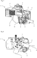
- FIG. 7 and 8 show a first preferred embodiment of the present invention. This first preferred embodiment has, with the exception of the differences described below, an identical embodiment to the first non-inventive embodiment.
- the device carrier 2 'in this fourth preferred embodiment has two interfaces 3, 3 ", which are each designed to receive and supply energy to a joining agent processing device 1.
- the first interface 3' is corresponding to the interface 3, which was described in the context of the first embodiment
- the interface 3 " is arranged in a clockwise direction around the coating unit interface 7 adjacent to the first interface 3 '.
- the interfaces 3, 3 " correlate to the design of the interface 3, as described in the context of the first preferred embodiment.
- the coating unit 1 of this fourth preferred embodiment is configured to provide the "hot melt adhesive joining technology" and the "laser joining technology".
- coating unit 1 has a joining agent processing device 4 'according to the embodiment described in the context of the first non-inventive embodiment, which is connected to the first interface 3', and a joining agent processing device 4 "according to the embodiment, as in the context of the third not inventive embodiment, which is connected to the second interface 3 ".
- the radiation outlet 12 and the melt adhesive outlet opening 8 of the devices 4 'and 4 " are preferably designed and oriented so that the conditioning of the edge band 6 takes place at the same or similar position for both technologies
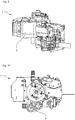
- Figs. 9 and 10 show a second preferred embodiment of the present invention, which corresponds to the first preferred embodiment except for the differences described below.
- the joining agent processing device 4 "of the second preferred embodiment is configured to provide the" hot gas joining technology.
- the joining agent processing device 4" is configured analogously to that of the second non-inventive embodiment.
- Third preferred embodiment Figs. 11 and 12 show a third preferred embodiment of the present invention. With the exception of the differences described below, the Embodiment of this third preferred embodiment of the first non-inventive embodiment.
- the coating unit 1 of this third embodiment is designed to provide all three joining technologies described above, more specifically, the "hot melt adhesive joining technology", the “laser joining technology” and the “hot gas joining technology”.
- the device carrier 2 "of this third preferred embodiment has a second and third interface for receiving and supplying power to a joining agent processing device, the interfaces being configured analogously to that of the first embodiment the three joining agent processing devices are arranged in a clockwise order around the coating unit interface 7, so that device 4 ', the "laser joining technology” device 4 "is arranged in front of the" hot-melt joining technology “device 4'” following the "hot-melt adhesive joining technology".
- the individual devices 4, 4 ", 4 '" are configured analogously to the corresponding devices in the embodiments described above n, more precisely, the hot melt outlet opening, the hot gas outlet and the radiation outlet are arranged in the same area, so that the preparation of the edge band takes place at the same or similar position.
Landscapes
- Life Sciences & Earth Sciences (AREA)
- Engineering & Computer Science (AREA)
- Mechanical Engineering (AREA)
- Wood Science & Technology (AREA)
- Forests & Forestry (AREA)
- Application Of Or Painting With Fluid Materials (AREA)
- Lining Or Joining Of Plastics Or The Like (AREA)
- Coating Apparatus (AREA)
Priority Applications (1)
| Application Number | Priority Date | Filing Date | Title |
|---|---|---|---|
| PL14750733T PL3033205T3 (pl) | 2013-08-14 | 2014-08-13 | Agregat powlekający |
Applications Claiming Priority (2)
| Application Number | Priority Date | Filing Date | Title |
|---|---|---|---|
| DE102013216113.1A DE102013216113A1 (de) | 2013-08-14 | 2013-08-14 | Beschichtungsaggregat |
| PCT/EP2014/067328 WO2015022362A1 (de) | 2013-08-14 | 2014-08-13 | Beschichtungsaggregat |
Publications (2)
| Publication Number | Publication Date |
|---|---|
| EP3033205A1 EP3033205A1 (de) | 2016-06-22 |
| EP3033205B1 true EP3033205B1 (de) | 2017-10-11 |
Family
ID=51352501
Family Applications (1)
| Application Number | Title | Priority Date | Filing Date |
|---|---|---|---|
| EP14750733.9A Active EP3033205B1 (de) | 2013-08-14 | 2014-08-13 | Beschichtungsaggregat |
Country Status (6)
| Country | Link |
|---|---|
| US (1) | US10105900B2 (pl) |
| EP (1) | EP3033205B1 (pl) |
| CN (1) | CN105451949B (pl) |
| DE (1) | DE102013216113A1 (pl) |
| PL (1) | PL3033205T3 (pl) |
| WO (1) | WO2015022362A1 (pl) |
Families Citing this family (6)
| Publication number | Priority date | Publication date | Assignee | Title |
|---|---|---|---|---|
| DE102014104034A1 (de) * | 2014-03-24 | 2015-09-24 | Wegoma Gmbh | Mobiles Kantenanleimgerät mit Zusatzheizung |
| IT201600128897A1 (it) * | 2016-12-20 | 2018-06-20 | Biesse Spa | Macchina per la bordatura di pannelli di legno o simili |
| IT201800001761A1 (it) * | 2018-01-24 | 2019-07-24 | Biesse Spa | Gruppo bordatore e metodo per la bordatura di pannelli di legno o simili |
| IT201800003189A1 (it) * | 2018-03-01 | 2019-09-01 | Biesse Spa | Macchina per la lavorazione di pannelli di legno o simili |
| DE102018208062A1 (de) | 2018-05-23 | 2019-11-28 | Homag Gmbh | Andrückvorrichtung zum Andrücken eines Beschichtungsmaterials gegen platten- oder leistenförmige Werkstücke |
| DE102019112600A1 (de) * | 2019-05-14 | 2020-11-19 | Felder Kg | Vorrichtung zur Beschichtung einer Oberfläche |
Family Cites Families (186)
| Publication number | Priority date | Publication date | Assignee | Title |
|---|---|---|---|---|
| US2118763A (en) | 1936-12-24 | 1938-05-24 | Masonite Corp | Burnishing of fiberboards |
| GB722485A (en) | 1952-10-21 | 1955-01-26 | Roberts Patent Filling Machine | Improvements in machines for filling, lidding and marking containers |
| SE309900B (pl) | 1963-09-16 | 1969-04-08 | Svenska Flaektfabriken Ab | |
| GB1123526A (en) | 1966-03-30 | 1968-08-14 | Ernst Ludvig Back | A method for sealing cellulose or lignocellulosic materials together or to other materials |
| US3676283A (en) | 1969-08-14 | 1972-07-11 | Grace W R & Co | Laminate and process for laminating with polythiol polyene reaction product |
| BE759393A (fr) | 1970-04-09 | 1971-04-30 | Dhj Ind Inc | Procede et appareil de liaison par application de |
| US3811915A (en) | 1971-04-27 | 1974-05-21 | Inmont Corp | Printing method for forming three dimensional simulated wood grain,and product formed thereby |
| US3975740A (en) | 1973-10-02 | 1976-08-17 | Siemens Aktiengesellschaft | Liquid jet recorder |
| DE2433719A1 (de) | 1974-07-13 | 1976-01-29 | Agfa Gevaert Ag | Tintenschreibvorrichtung fuer das inkjet-verfahren |
| SE396199B (sv) | 1975-03-11 | 1977-09-12 | Casco Ab | Sett for beleggning av kanterna hos span- och trefiberskivor och liknande cellulosabaserade formkroppar |
| DE2532503B2 (de) | 1975-07-21 | 1978-02-23 | IMA-Klessmann KG, 4830 Gutersloh | Verfahren zum anleimen von kantenmaterial an die kanten plattenfoermiger werkstuecke aus holzwerkstoff |
| SE421055B (sv) | 1978-04-19 | 1981-11-23 | Klaus Mielke | Anordning for merkning av kollin eller andra foremal |
| US4222812A (en) | 1978-06-29 | 1980-09-16 | Lof Plastics, Inc. | Hot air edge banding machine |
| EP0036297A3 (en) | 1980-03-14 | 1981-10-07 | Willett International Limited | Ink jet printing apparatus and process |
| US4514742A (en) | 1980-06-16 | 1985-04-30 | Nippon Electric Co., Ltd. | Printer head for an ink-on-demand type ink-jet printer |
| DE3219508A1 (de) | 1982-05-25 | 1983-12-01 | Interprint Rotationsdruck GmbH & Co. KG, 5760 Arnsberg | Schichtstoff und verfahren zu seiner herstellung |
| NZ207387A (en) | 1984-03-11 | 1988-10-28 | Michael John Blackwood Sewell | Sander with counter-reciprocating plates |
| JPS60264285A (ja) | 1984-06-13 | 1985-12-27 | Pilot Ink Co Ltd | 可逆性感熱記録組成物 |
| US5113757A (en) | 1986-01-10 | 1992-05-19 | Alliance Rubber Company, Inc. | Method and apparatus for making printed elastic bands |
| FR2601265B1 (fr) | 1986-05-28 | 1988-08-05 | Cherubin Grillo Victor | Systeme pictural d'impression polychrome point par point sur une surface plane ou en relief, commande par micro-processeur. |
| US4814795A (en) | 1987-05-01 | 1989-03-21 | Marsh Company | Ink jet head holder |
| US5254844A (en) | 1988-05-11 | 1993-10-19 | Symbol Technologies, Inc. | Mirrorless scanners with movable laser, optical and sensor components |
| JPH026164A (ja) | 1988-06-24 | 1990-01-10 | Nec Data Terminal Ltd | カードインプリントプリンタ |
| US4894262A (en) | 1988-10-24 | 1990-01-16 | Api, Inc. | Lumber end sealing machine |
| JPH03205A (ja) | 1989-05-26 | 1991-01-07 | Norin Suisansyo Shinrin Sogo Kenkyusho | 表面加熱による集成材の製造方法とその装置 |
| DE4039742A1 (de) | 1990-12-08 | 1992-06-11 | Francotyp Postalia Gmbh | Fluessigkeitsstrahl-druckvorrichtung fuer frankier- und wertstempelmaschinen |
| DE69230220T2 (de) | 1991-02-08 | 2000-06-21 | Cambridge Neuroscience Research, Inc. | Substituierte guanidine und derivate hiervon als modulatoren der freisetzung von neurotransmittern und neue methode zur identifizierung von inhibitoren der neurotransmitter-freisetzung |
| US5485685A (en) | 1992-04-10 | 1996-01-23 | Eiwa Co., Ltd. | Wood treating method |
| US5331143A (en) | 1992-08-28 | 1994-07-19 | Symbol Technologies, Inc. | Optical scanner using an axicon and an aperture to aspherically form the scanning beam |
| US5607536A (en) | 1992-10-30 | 1997-03-04 | Tikka-System Oy | Method and apparatus for coating objects with a plastic film |
| US5824373A (en) | 1994-04-20 | 1998-10-20 | Herbert's Powder Coatings, Inc. | Radiation curing of powder coatings on wood |
| US5935331A (en) | 1994-09-09 | 1999-08-10 | Matsushita Electric Industrial Co., Ltd. | Apparatus and method for forming films |
| US5530537A (en) | 1994-09-15 | 1996-06-25 | Xerox Corporation | Biased foam roll cleaner |
| FR2725385B1 (fr) | 1994-10-06 | 1996-12-20 | Lebioda Robert | Procede et installation de peinture par voie electrostatique de pieces en materiau dielectrique ou faiblement conducteur et electrode utilisee |
| JPH08119239A (ja) | 1994-10-31 | 1996-05-14 | Sony Corp | カートン処理システム及びカートン処理方法 |
| US5581284A (en) | 1994-11-25 | 1996-12-03 | Xerox Corporation | Method of extending the life of a printbar of a color ink jet printer |
| US6180172B1 (en) | 1994-11-29 | 2001-01-30 | Henkel Kommanditgesellschaft Auf Aktien | Process and apparatus for treating surfaces |
| US6053231A (en) | 1995-03-23 | 2000-04-25 | Osaka Sealing Printing Co., Ltd. | Bonding apparatus for cutting label continuum having labels formed thereon and bonding label to object |
| DE19517808A1 (de) * | 1995-05-15 | 1996-11-21 | Homag Maschinenbau Ag | Bearbeitungszentrum mit einer Spindeleinheit zur Aufnahme von Bearbeitungswerkzeugen und Bearbeitungsaggregaten für Holz- und Kunststoff-Werkstoffe |
| DE19518925A1 (de) | 1995-05-23 | 1996-11-28 | Homag Maschinenbau Ag | Verfahren und Vorrichtung zur Durchlauf-Bearbeitung von im wesentlichen flächigen oder leistenförmigen Werkstücken aus offenporigen Holzwerkstoffen und dergleichen im Kantenbereich |
| US5643983A (en) | 1995-08-30 | 1997-07-01 | Ashland Inc. | Moisture curable 100% solids one component plywood adhesive |
| DE19532724A1 (de) | 1995-09-05 | 1997-03-06 | Tampoprint Gmbh | Mehrfarbendruckvorrichtung |
| EP1015135B1 (en) | 1996-01-11 | 2005-06-08 | ROSS, Gregory Edye | Perimeter coating alignment method |
| JP3658714B2 (ja) | 1996-02-09 | 2005-06-08 | アイン興産株式会社 | 木質合成板の模様形成方法 |
| JP3084606B2 (ja) | 1996-02-26 | 2000-09-04 | 荘太郎 津田 | 木質板材の製造方法とその装置 |
| GB9609379D0 (en) | 1996-05-03 | 1996-07-10 | Willett Int Ltd | Mechanism and method |
| CN1096946C (zh) | 1996-06-20 | 2002-12-25 | 佳能株式会社 | 通过气泡与大气的连通进行喷液的方法和设备 |
| FI2664U1 (fi) | 1996-07-16 | 1996-11-29 | Valmet Corp | Laitteisto kartonkirainan kalanteroimiseksi |
| JPH10157245A (ja) | 1996-11-27 | 1998-06-16 | Seiko Precision Kk | 印字装置 |
| JPH10226045A (ja) | 1997-02-12 | 1998-08-25 | Tokyo Enbosu Kogyo Kk | エンボス加工板の加工・着色装置 |
| US6072509A (en) | 1997-06-03 | 2000-06-06 | Eastman Kodak Company | Microfluidic printing with ink volume control |
| DE69808772T2 (de) | 1997-08-01 | 2003-02-27 | Videojet Technologies Inc., Wood Dale | Vorrichtung zur selbstinbetriebstellung eines tintenstrahldruckers |
| US5986680A (en) | 1997-08-29 | 1999-11-16 | Eastman Kodak Company | Microfluidic printing using hot melt ink |
| DE19742825B4 (de) | 1997-09-27 | 2010-01-21 | Hohenloher Spezialmöbelwerk Schaffitzel GmbH + Co. | Verfahren zum Aufbringen einer Lineatur und Tafel mit einer Lineatur |
| US6136408A (en) | 1997-11-25 | 2000-10-24 | J. M. Huber Corporation | Surface treatment for wood materials including oriented strand board |
| EP0931649A3 (en) | 1998-01-27 | 2000-04-26 | Eastman Kodak Company | Apparatus and method for making a contoured surface having complex topology |
| US6578276B2 (en) | 1998-01-27 | 2003-06-17 | Eastman Kodak Company | Apparatus and method for marking multiple colors on a contoured surface having a complex topography |
| US5950382A (en) | 1998-02-06 | 1999-09-14 | Mdf Inc. | Flat skinned door that simulates a three-dimensional molded skin door and corresponding method |
| GB2335885A (en) | 1998-03-28 | 1999-10-06 | Markem Tech Ltd | Method of printing on conveyed articles |
| DK173410B1 (da) | 1998-04-07 | 2000-09-25 | Ulmadan Aps | Fremgangsmåde, anlæg samt anvendelse af fremgangsmåde og anlæg til påføring af lak |
| DE19823195C2 (de) | 1998-05-23 | 2003-03-20 | Doellken & Co Gmbh W | Verfahren und Vorrichtung zum Bedrucken von Kunststoffwerkstückoberflächen |
| US6092343A (en) | 1998-07-16 | 2000-07-25 | Therma-Tru Corporation | Compression molded door assembly |
| DE19836566A1 (de) * | 1998-08-12 | 2000-02-17 | Homag Maschinenbau Ag | Bearbeitungszentrum mit Heißprägeaggregat, einwechselbares Heißprägeaggregat und Bearbeitungszentrum mit speziellem Speichermagazin für ein derartiges Heißprägeaggregat |
| US6472053B1 (en) | 1998-10-07 | 2002-10-29 | Nippon Paper Industries Co., Ltd. | Ink jet recording sheet |
| IT1304910B1 (it) | 1998-10-14 | 2001-04-05 | Giovanni Fattori | Macchina chiodatrice |
| KR100603680B1 (ko) | 1998-12-03 | 2006-07-20 | 아크조 노벨 엔.브이. | 장식된 기재의 제조방법 |
| DE19857045C2 (de) | 1998-12-10 | 2001-02-01 | Industrieservis Ges Fuer Innov | Beschichtung von Gegenständen |
| DE19907043B4 (de) | 1999-02-19 | 2005-03-24 | Karl Otto Braun Kg | Thermoplastisches Verbandmaterial und Verfahren zu dessen Herstellung |
| US6694872B1 (en) | 1999-06-18 | 2004-02-24 | Holographic Label Converting, Inc. | In-line microembossing, laminating, printing, and diecutting |
| US6286920B1 (en) | 1999-07-29 | 2001-09-11 | Paul Anthony Ridgway | Venetian blind printing system |
| SE515206C2 (sv) | 1999-10-27 | 2001-06-25 | Bpb Gyproc Nordic East Ab | Sätt vid behandling av gipsskivor eller -plattor |
| DE19955575B4 (de) | 1999-11-18 | 2010-04-08 | Brandt Kantentechnik Gmbh | Verfahren und Vorrichtung zum Anhaften eines Deckmaterials an Werkstückoberflächen von fortlaufend bewegten oder stationär angeordneten platten- oder leistenförmigen Werkstücken |
| SE516696C2 (sv) | 1999-12-23 | 2002-02-12 | Perstorp Flooring Ab | Förfarande för framställning av ytelement vilka innefattar ett övre dekorativt skikt samt ytelement framställda enlit förfarandet |
| IT1317205B1 (it) | 2000-04-11 | 2003-05-27 | Comital S P A | Metodo per la realizzazione di decorazioni policrome a stampa sumanufatti metallici e relativa apparecchiatura |
| US20020160114A1 (en) | 2000-05-05 | 2002-10-31 | Michael Cozzolino | Method of manufacturing decorative wood products from engineered wood products |
| US6428871B1 (en) | 2000-05-05 | 2002-08-06 | Michael Cozzolino | Method of manufacturing decorative wood products from engineered wood products |
| DE10031030B4 (de) | 2000-06-26 | 2005-08-04 | Bauer, Jörg R. | Verfahren und Vorrichtung zum Herstellen flächiger Bauteile mit vorbestimmtem Oberflächenaussehen und flächiges Bauteil, insbesondere Frontplatte eines Küchenelements |
| JP2002037224A (ja) | 2000-07-21 | 2002-02-06 | Fuji Photo Film Co Ltd | 梱包体の製造方法、梱包体、及び印刷装置 |
| US7273651B1 (en) | 2000-08-15 | 2007-09-25 | Wilde Rose Z | Crackle finish |
| US6755518B2 (en) | 2001-08-30 | 2004-06-29 | L&P Property Management Company | Method and apparatus for ink jet printing on rigid panels |
| EP1190864A1 (de) | 2000-09-21 | 2002-03-27 | GRETAG IMAGING Trading AG | Verfahren und Vorrichtung zum Drucken von digitaler Bildinformation |
| US6930696B2 (en) | 2000-09-27 | 2005-08-16 | Seiko Epson Corporation | Printing up to edges of printing paper without platen soiling |
| AU2002239731A1 (en) | 2000-11-13 | 2002-06-03 | Imaging Alternatives, Inc. | Wood surface inkjet receptor medium and method of making and using same |
| GB0101186D0 (en) | 2001-01-17 | 2001-02-28 | Dolphin Packaging Materials Lt | Printing process and apparatus |
| US6789876B2 (en) | 2001-03-21 | 2004-09-14 | Aaron G. Barclay | Co-operating mechanical subassemblies for a scanning carriage, digital wide-format color inkjet print engine |
| US20020189754A1 (en) | 2001-04-30 | 2002-12-19 | Hill David A. | System and method for forming wood products |
| DE10122573A1 (de) | 2001-05-09 | 2002-11-14 | Winkler & Duennebier Ag | Klebestation für eine Maschine zum Herstellen von Briefhüllen, Versandbeuteln und dergleichen |
| DE10130509A1 (de) | 2001-06-25 | 2003-01-09 | Dieffenbacher Gmbh Maschf | Verfahren zur Herstellung von Holzwerkstoffplatten |
| US20030020767A1 (en) | 2001-07-24 | 2003-01-30 | Saksa Thomas A. | Grain forming ink jet printer for printing a grain on a workpiece and method of assembling the printer |
| DE10139633C1 (de) | 2001-08-11 | 2003-04-24 | Amtec Kistler Gmbh | Vorrichtung zum Auftragen eines Beschichtungsmittels |
| US20030048343A1 (en) | 2001-08-30 | 2003-03-13 | Anderson Brian L. | Process for preparing a laminated ink jet print |
| US20050274272A1 (en) | 2001-10-09 | 2005-12-15 | Ralph Machesky | Multipurpose label apparatus |
| US7556708B2 (en) | 2003-06-13 | 2009-07-07 | Advanced Label Systems, Inc. | Apparatus and method for applying labels |
| US7066680B2 (en) | 2001-12-04 | 2006-06-27 | Integrated Paving Concepts Inc. | Method of forming an inlaid pattern in an asphalt surface |
| GB0130485D0 (en) | 2001-12-21 | 2002-02-06 | Plastic Logic Ltd | Self-aligned printing |
| US20030217807A1 (en) | 2002-01-25 | 2003-11-27 | Leif Lesmann | Method and apparatus for gluing |
| GB2384931B (en) | 2002-01-30 | 2005-06-29 | Hewlett Packard Co | Printer device and method |
| JP3838964B2 (ja) | 2002-03-13 | 2006-10-25 | 株式会社リコー | 機能性素子基板の製造装置 |
| KR100448328B1 (ko) | 2002-03-19 | 2004-09-10 | 이강 | 마이크로웨이브를 이용한 드라이필름 라미네이팅 장치 및방법 |
| KR100990448B1 (ko) | 2002-04-03 | 2010-10-29 | 메이소나이트 코오포레이션 | 물품에 상을 만드는 방법 |
| US20040123966A1 (en) | 2002-04-11 | 2004-07-01 | Altman Thomas E. | Web smoothness improvement process |
| JP4543617B2 (ja) | 2002-04-22 | 2010-09-15 | セイコーエプソン株式会社 | アクティブマトリクス基板の製造方法、電気光学装置の製造方法、電子機器の製造方法、アクティブマトリクス基板の製造装置、電気光学装置の製造装置、及び電気機器の製造装置 |
| WO2003096257A2 (de) | 2002-05-08 | 2003-11-20 | Erich Utsch Ag | Kraftfahrzeug-kennzeichenschilder |
| US20030211251A1 (en) | 2002-05-13 | 2003-11-13 | Daniels Evan R. | Method and process for powder coating molding |
| US6634729B1 (en) | 2002-06-12 | 2003-10-21 | J.M. Huber Corporation | Apparatus for applying ink indicia to boards |
| US20050098285A1 (en) | 2002-06-24 | 2005-05-12 | Richard Aust | Machine for making/treating a sheet of material |
| US6964722B2 (en) | 2002-08-07 | 2005-11-15 | Trio Industries Holdings, L.L.C. | Method for producing a wood substrate having an image on at least one surface |
| WO2004016438A1 (en) | 2002-08-19 | 2004-02-26 | Creo Il. Ltd. | Continuous flow inkjet utilized for 3d curved surface printing |
| DE10239630B3 (de) | 2002-08-23 | 2004-04-08 | Espera-Werke Gmbh | Vorrichtung und Verfahren zum Etikettieren von Gegenständen |
| ES2225709T3 (es) | 2002-10-02 | 2005-03-16 | Leister Process Technologies | Procedimiento y dispositivo para trabajar piezas con rayos laser. |
| US6819886B2 (en) | 2002-10-23 | 2004-11-16 | Nex Press Solutions Llc | Gloss/density measurement device with feedback to control gloss and density of images produced by an electrographic reproduction apparatus |
| US6790335B2 (en) | 2002-11-15 | 2004-09-14 | Hon Hai Precision Ind. Co., Ltd | Method of manufacturing decorative plate |
| ITMO20020369A1 (it) | 2002-12-30 | 2004-06-30 | Tecno Europa Srl | Sistema per stampare oggetti. |
| US6981767B2 (en) | 2003-01-15 | 2006-01-03 | Ssgii, Inc. | Printed item having an image with a high durability and/or resolution |
| JP4225076B2 (ja) | 2003-02-19 | 2009-02-18 | セイコーエプソン株式会社 | 液滴吐出装置 |
| JP2004335492A (ja) | 2003-03-07 | 2004-11-25 | Junji Kido | 有機電子材料の塗布装置およびそれを使用した有機電子素子の製造方法 |
| DE10323412B4 (de) | 2003-05-23 | 2007-07-05 | Bauer, Jörg R. | Verfahren und Vorrichtung zum Herstellen eines Bauteils mit einer Oberfläche vorbestimmten Aussehens |
| BR0313325A (pt) | 2003-06-24 | 2005-06-14 | Huber Corp J M | Aparelho para aplicar desenhos de tinta sobre painéis |
| JP2005059215A (ja) | 2003-08-08 | 2005-03-10 | Sharp Corp | 静電吸引型流体吐出装置 |
| JP4387727B2 (ja) | 2003-08-14 | 2009-12-24 | 富士通株式会社 | 部品実装組立セル |
| DE10362218B4 (de) | 2003-09-06 | 2010-09-16 | Kronotec Ag | Verfahren zum Versiegeln einer Bauplatte |
| DE10342723B4 (de) | 2003-09-16 | 2005-12-15 | Delle Vedove Maschinenbau Gmbh | Wärmetauschervorrichtung |
| KR101048371B1 (ko) | 2003-11-21 | 2011-07-11 | 삼성전자주식회사 | 액적 공급 설비, 이를 이용한 표시장치의 제조 방법 |
| US7534299B2 (en) | 2003-12-18 | 2009-05-19 | Rhino Hide Llc | Method and apparatus for spraying trusses with a mold and insect preventative solution |
| DE202004000662U1 (de) | 2004-01-17 | 2004-04-08 | Homag Holzbearbeitungssysteme Ag | Maschine zum Bedrucken der Schmalseiten plattenförmiger Werkstücke |
| AT503091A2 (de) | 2004-02-04 | 2007-07-15 | Thoma & Harms Holz Gmbh | Verfahren zum verdichten einer oberfläche eines holzwerkstückes und vorrichtung hierzu |
| US7354845B2 (en) | 2004-08-24 | 2008-04-08 | Otb Group B.V. | In-line process for making thin film electronic devices |
| US20050279450A1 (en) | 2004-06-16 | 2005-12-22 | Kevin King | Method and apparatus for producing laminated products of infinite length |
| US8709296B2 (en) | 2004-06-25 | 2014-04-29 | Mitsubishi Materials Corporation | Metal colloidal particles, metal colloid and use of metal colloid |
| JP4508762B2 (ja) | 2004-07-29 | 2010-07-21 | 大日本スクリーン製造株式会社 | 印刷検査装置およびこれを備えた印刷装置、並びに印刷検査方法 |
| JP2006051816A (ja) | 2004-07-30 | 2006-02-23 | Heidelberger Druckmas Ag | 印刷像を印刷して後処理する方法 |
| US20060075917A1 (en) | 2004-10-08 | 2006-04-13 | Edwards Paul A | Smooth finish UV ink system and method |
| CN1311913C (zh) | 2004-10-28 | 2007-04-25 | 博奥生物有限公司 | 一种微量液体喷射系统 |
| EP1743775A1 (en) | 2005-07-13 | 2007-01-17 | SAPPI Netherlands Services B.V. | Coated paper for sheet fed offset printing |
| JP2006187723A (ja) | 2005-01-06 | 2006-07-20 | Konica Minolta Medical & Graphic Inc | 塗布装置及びダイコータの作製方法 |
| JP2006231621A (ja) | 2005-02-23 | 2006-09-07 | Eidai Co Ltd | 突き板貼り化粧材の製造方法とそこで用いられる圧締盤 |
| ES2424849T3 (es) | 2005-03-04 | 2013-10-09 | Inktec Co., Ltd. | Tintas conductoras y método de fabricación de las mismas |
| US20100059176A1 (en) | 2005-04-01 | 2010-03-11 | Eiichi Ito | Multilayer Information Recording Medium, and Apparatus and Method for Manufacturing Same |
| JP4584003B2 (ja) | 2005-04-07 | 2010-11-17 | セイコーエプソン株式会社 | ラベル作成装置のラベル作成方法、およびラベル作成装置 |
| EP1714884A1 (en) | 2005-04-21 | 2006-10-25 | Glaxo Group Limited | Apparatus and method for printing packaging elements |
| PL1726443T3 (pl) | 2005-04-28 | 2007-10-31 | Homag Holzbearbeitungssysteme Ag | Urządzenie i sposób dekorowania wąskich boków płytowych detali |
| DE102005020119B3 (de) | 2005-04-29 | 2006-06-08 | Homag Holzbearbeitungssysteme Ag | Fertigungssystem |
| EP1877232B1 (de) | 2005-05-02 | 2014-05-14 | Basf Se | Verfahren zur behandlung von holzoberflächen |
| US20060275590A1 (en) | 2005-06-03 | 2006-12-07 | Lorenz Daniel W | Method of printing a durable UV cured ink design on a substrate |
| FR2886880B1 (fr) | 2005-06-14 | 2008-10-03 | Mgi France Sa | Machine numerique a jet pour depose d'un revetement sur un substrat |
| WO2007002135A2 (en) | 2005-06-21 | 2007-01-04 | Trace Bio Analytics, Llc | Non-signal imidazole reagents for mass spectrometry analysis of phosphomonoesters |
| CN101248489A (zh) | 2005-08-03 | 2008-08-20 | 三菱化学媒体株式会社 | 光记录介质及油墨组合物 |
| US20070044324A1 (en) | 2005-08-30 | 2007-03-01 | Arthur Harris | Power Tool Attachments |
| KR100708469B1 (ko) | 2005-10-24 | 2007-04-18 | 삼성전자주식회사 | 사용노즐 자동조절장치, 그것을 구비하는 화상형성장치 및그 사용노즐 자동조절방법 |
| ES2380041T3 (es) | 2005-11-23 | 2012-05-08 | Homag Holzbearbeitungssysteme Ag | Procedimiento para el recubrimiento de componentes |
| DE202006000270U1 (de) | 2006-01-10 | 2006-04-06 | Khs Maschinen- Und Anlagenbau Ag | Vorrichtung zum Bedrucken von Flaschen o.dgl. Behälter |
| PL1839883T3 (pl) | 2006-03-08 | 2017-08-31 | Homag Holzbearbeitungssysteme Ag | Sposób i urządzenie do zadrukowywania półwyrobów w kształcie płyty |
| EP1892107B1 (de) | 2006-08-25 | 2009-11-04 | Homag Holzbearbeitungssysteme AG | Vorrichtung zum Bemustern von Werkstücken |
| DE102006021171A1 (de) | 2006-05-06 | 2007-11-08 | W. Döllken & Co. GmbH | Deckleiste |
| US7669947B2 (en) | 2006-05-10 | 2010-03-02 | Rsi Systems, Llc | Industrial ink jet print head system |
| ITMI20061227A1 (it) | 2006-06-26 | 2007-12-27 | Dante Frati | Procedimento per stampare superfici di elementi piani a base di legno |
| US7494272B2 (en) | 2006-06-27 | 2009-02-24 | Applied Materials, Inc. | Dynamic surface annealing using addressable laser array with pyrometry feedback |
| US8733274B2 (en) | 2006-10-20 | 2014-05-27 | Hewlett-Packard Development Company, L.P. | Tube mounted inkjet printhead die |
| BRPI0717531A2 (pt) | 2006-10-25 | 2013-10-22 | Basf Se | Uso de compostos, formulações aquosas contendo aglutinante, combinação, processo para o tratamento de substratos, substratos, e, processo para a produção de formulações aquosas contendo aglutinante |
| ES2402367T3 (es) | 2006-12-20 | 2013-05-03 | Homag Holzbearbeitungssysteme Ag | Dispositivo y procedimiento para recubrir piezas |
| DE102006062446A1 (de) | 2006-12-23 | 2008-06-26 | Öz, Bülent | Verfahren zum Transferdrucken sowie Druckvorlagen für diese Zwecke |
| EP2168746B1 (en) | 2007-06-14 | 2018-04-18 | Aji Co., Ltd. | Method and apparatus for moulding aspherical lenses |
| MX2009013258A (es) | 2007-07-12 | 2010-01-25 | Cytec Surface Specialties Sa | Composiciones de aceite natural acrilado. |
| WO2009015850A2 (de) | 2007-08-02 | 2009-02-05 | Kuka Systems Gmbh | Drehanschlusskupplung |
| DE202007011911U1 (de) | 2007-08-24 | 2009-01-08 | Rehau Ag + Co | Kantenleiste für Möbelstücke |
| US7762647B2 (en) | 2007-09-25 | 2010-07-27 | Eastman Kodak Company | MEMS printhead based compressed fluid printing system |
| US20090120249A1 (en) | 2007-11-14 | 2009-05-14 | Achim Gauss | Device For Refining Workpieces |
| US20090133361A1 (en) | 2007-11-27 | 2009-05-28 | Southern Cross Building Products, Llc | High-performance environmentally friendly building panel and related manufacturing methods |
| US20100285289A1 (en) | 2008-01-09 | 2010-11-11 | Oke Nollet | Floor covering, formed from floor panels and method for manufacturing such floor panels |
| CN101687214B (zh) | 2008-03-24 | 2014-04-16 | 日本碍子株式会社 | 涂敷膜形成方法以及涂敷膜形成装置 |
| US20090252933A1 (en) | 2008-04-04 | 2009-10-08 | 3M Innovative Properties Company | Method for digitally printing electroluminescent lamps |
| ITMO20080106A1 (it) | 2008-04-15 | 2009-10-16 | Scm Group Spa | Metodo e macchina per preparare alla bordatura un pannello |
| BE1018177A3 (nl) | 2008-06-10 | 2010-06-01 | Flooring Ind Ltd Sarl | Bedrukt substraat, werkwijze voor het vervaardigen van vloerpanelen en werkwijze voor het vervaardigen van bedrukte substraten. |
| EP2313252B1 (de) | 2008-07-21 | 2016-06-15 | Karl W. Niemann GmbH & Co. KG | Verfahren und vorrichtung zur anbringung von kantenbändern auf schmalflächen von werkstücken |
| DE102008055971A1 (de) * | 2008-11-05 | 2010-05-06 | Komet Group Gmbh | Bearbeitungszentrum mit Drehübertrager für elektrische Energie |
| TWI478990B (zh) | 2009-04-09 | 2015-04-01 | Sicpa Holding Sa | 明亮之磁性凹刻印刷油墨 |
| EP2243619B2 (de) * | 2009-04-22 | 2022-03-16 | Homag Holzbearbeitungssysteme AG | Vorrichtung und Verfahren zum Beschichten von Werkstücken |
| US20110017082A1 (en) | 2009-07-27 | 2011-01-27 | Raimon Castells | Printing system |
| DE202009016509U1 (de) * | 2009-12-04 | 2011-04-14 | Homag Holzbearbeitungssysteme Ag | 5-Achsbearbeitungszentrum mit Anleimaggregat |
| DE102010008295A1 (de) | 2010-02-17 | 2011-08-18 | Dieffenbacher System Automation GmbH, 75031 | Vorrichtung und Verfahren zum Bedrucken von Oberflächen von Werkstoffplatten, insbesondere Holzplatten, mit einer mehrfarbigen Abbildung |
| DE202010009174U1 (de) * | 2010-06-17 | 2011-11-21 | Homag Holzbearbeitungssysteme Ag | Einwechselbares Beschichtungsaggregat |
| DE102011014995A1 (de) * | 2011-03-25 | 2012-09-27 | Ima Klessmann Gmbh Holzbearbeitungssysteme | Vorrichtung zur Bearbeitung von Werkstücken |
| CN102229169A (zh) * | 2011-06-17 | 2011-11-02 | 山西飞虹激光科技有限公司 | 激光封边方法 |
| US8544769B2 (en) | 2011-07-26 | 2013-10-01 | General Electric Company | Multi-nozzle spray gun |
| CN103072179A (zh) * | 2012-12-28 | 2013-05-01 | 青岛华顺昌木工机械制造有限公司 | 封边机胶锅快速更换装置 |
| US8721396B1 (en) | 2013-03-12 | 2014-05-13 | BTD Wood Powder Coating, Inc. | Method for preparing and buffing a powder coated wood substrate |
-
2013
- 2013-08-14 DE DE102013216113.1A patent/DE102013216113A1/de active Pending
-
2014
- 2014-08-13 PL PL14750733T patent/PL3033205T3/pl unknown
- 2014-08-13 US US14/911,309 patent/US10105900B2/en active Active
- 2014-08-13 EP EP14750733.9A patent/EP3033205B1/de active Active
- 2014-08-13 WO PCT/EP2014/067328 patent/WO2015022362A1/de not_active Ceased
- 2014-08-13 CN CN201480045122.0A patent/CN105451949B/zh active Active
Non-Patent Citations (1)
| Title |
|---|
| None * |
Also Published As
| Publication number | Publication date |
|---|---|
| US20160200036A1 (en) | 2016-07-14 |
| CN105451949A (zh) | 2016-03-30 |
| WO2015022362A1 (de) | 2015-02-19 |
| EP3033205A1 (de) | 2016-06-22 |
| CN105451949B (zh) | 2018-05-11 |
| DE102013216113A1 (de) | 2015-03-05 |
| US10105900B2 (en) | 2018-10-23 |
| PL3033205T3 (pl) | 2018-01-31 |
Similar Documents
| Publication | Publication Date | Title |
|---|---|---|
| EP3033205B1 (de) | Beschichtungsaggregat | |
| EP2365899B1 (de) | Vorrichtung zum beschichten von werkstücken | |
| EP2243619B2 (de) | Vorrichtung und Verfahren zum Beschichten von Werkstücken | |
| EP2826136B1 (de) | Lamellenpaket und verfahren zu seiner herstellung | |
| EP2332718B1 (de) | 5-Achsbearbeitungszentrum mit Anleimaggregat | |
| EP2782725B1 (de) | DÜSENANORDNUNG FÜR EINE KANTENSTREIFENAUFBRINGVORRICHTUNG ZUR BEAUFSCHLAGUNG EINES KLEBERLOSEN WÄRMEAKTIVIERBAREN ODER MIT HEIßKLEBER BESCHICHTETEN KANTENSTREIFENS ODER WERKSTÜCKS MIT HEIßLUFT UND KANTENSTREIFENAUFBRINGVORRICHTUNG MIT EINER DÜSENANORDNUNG | |
| EP2433769B1 (de) | Vorrichtung und Verfahren zum Beschichten eines Werkstücks | |
| EP1386720B1 (de) | Verfahren zum Beschichten von plattenförmigen Werkstücken mit einer Dekorfolie | |
| EP1154891B1 (de) | Durchlaufverfahren und vorrichtung zum anbringen eines beschichtungsmaterials an porösen schmalseiten von werkstücken | |
| EP2463097B1 (de) | Spotkaschierung mit Folie | |
| EP2397287B1 (de) | Einwechselbares Beschichtungsaggregat | |
| EP2964447B1 (de) | Verfahren zum aufbringen einer beschichtung auf werkstücke und vorrichtung zum beschichten von werkstücken | |
| EP1714756A1 (de) | Bearbeitungszentrum zum Bearbeiten von plattenförmigen Werkstücken | |
| DE102009006535B3 (de) | Prägevorrichtung und Prägeverfahren | |
| DE102010004092A1 (de) | Vorrichtung und Verfahren zur Bekantung von Werkstücken | |
| EP2324977A2 (de) | Vorrichtung zum Verleimen eines Kantenmaterials | |
| EP2769815B1 (de) | Vorrichtung und Verfahren zum Beschichten von Werkstücken | |
| EP3318378A1 (de) | Verfahren zur beschichtung unsteter oberflächen, vorrichtung sowie bauelement | |
| EP2934877B1 (de) | Kantenumleimer | |
| EP3790715A1 (de) | Vorrichtung und verfahren zum anbringen von kantenstreifen | |
| EP4013583B1 (de) | Einwechselbares bearbeitungsaggregat | |
| EP3653353B1 (de) | Vorrichtung und verfahren zum beschichten eines werkstücks | |
| DE102015206130B3 (de) | Verfahren, Vorrichtung und System zur Herstellung von Schichtholz | |
| DE102009056441B4 (de) | Verfahren zum Herstellen von Paneelen, insbesondere Fußbodenpaneelen | |
| DE102017206137A1 (de) | Stanzniet, Stanznietvorrichtung zum Setzen eines Stanzniets mit einer eine Stempelkraft unterstützenden Schwingung und Verfahren zum Stanznieten mit einer solchen Stanznietvorrichtung |
Legal Events
| Date | Code | Title | Description |
|---|---|---|---|
| PUAI | Public reference made under article 153(3) epc to a published international application that has entered the european phase |
Free format text: ORIGINAL CODE: 0009012 |
|
| 17P | Request for examination filed |
Effective date: 20160121 |
|
| AK | Designated contracting states |
Kind code of ref document: A1 Designated state(s): AL AT BE BG CH CY CZ DE DK EE ES FI FR GB GR HR HU IE IS IT LI LT LU LV MC MK MT NL NO PL PT RO RS SE SI SK SM TR |
|
| AX | Request for extension of the european patent |
Extension state: BA ME |
|
| RAP1 | Party data changed (applicant data changed or rights of an application transferred) |
Owner name: HOMAG GMBH |
|
| DAX | Request for extension of the european patent (deleted) | ||
| GRAP | Despatch of communication of intention to grant a patent |
Free format text: ORIGINAL CODE: EPIDOSNIGR1 |
|
| INTG | Intention to grant announced |
Effective date: 20170626 |
|
| GRAS | Grant fee paid |
Free format text: ORIGINAL CODE: EPIDOSNIGR3 |
|
| GRAA | (expected) grant |
Free format text: ORIGINAL CODE: 0009210 |
|
| AK | Designated contracting states |
Kind code of ref document: B1 Designated state(s): AL AT BE BG CH CY CZ DE DK EE ES FI FR GB GR HR HU IE IS IT LI LT LU LV MC MK MT NL NO PL PT RO RS SE SI SK SM TR |
|
| REG | Reference to a national code |
Ref country code: GB Ref legal event code: FG4D Free format text: NOT ENGLISH |
|
| REG | Reference to a national code |
Ref country code: CH Ref legal event code: EP |
|
| REG | Reference to a national code |
Ref country code: IE Ref legal event code: FG4D Free format text: LANGUAGE OF EP DOCUMENT: GERMAN |
|
| REG | Reference to a national code |
Ref country code: AT Ref legal event code: REF Ref document number: 935607 Country of ref document: AT Kind code of ref document: T Effective date: 20171115 |
|
| REG | Reference to a national code |
Ref country code: DE Ref legal event code: R096 Ref document number: 502014005798 Country of ref document: DE |
|
| REG | Reference to a national code |
Ref country code: NL Ref legal event code: MP Effective date: 20171011 |
|
| REG | Reference to a national code |
Ref country code: LT Ref legal event code: MG4D |
|
| PG25 | Lapsed in a contracting state [announced via postgrant information from national office to epo] |
Ref country code: NL Free format text: LAPSE BECAUSE OF FAILURE TO SUBMIT A TRANSLATION OF THE DESCRIPTION OR TO PAY THE FEE WITHIN THE PRESCRIBED TIME-LIMIT Effective date: 20171011 |
|
| PG25 | Lapsed in a contracting state [announced via postgrant information from national office to epo] |
Ref country code: FI Free format text: LAPSE BECAUSE OF FAILURE TO SUBMIT A TRANSLATION OF THE DESCRIPTION OR TO PAY THE FEE WITHIN THE PRESCRIBED TIME-LIMIT Effective date: 20171011 Ref country code: ES Free format text: LAPSE BECAUSE OF FAILURE TO SUBMIT A TRANSLATION OF THE DESCRIPTION OR TO PAY THE FEE WITHIN THE PRESCRIBED TIME-LIMIT Effective date: 20171011 Ref country code: NO Free format text: LAPSE BECAUSE OF FAILURE TO SUBMIT A TRANSLATION OF THE DESCRIPTION OR TO PAY THE FEE WITHIN THE PRESCRIBED TIME-LIMIT Effective date: 20180111 Ref country code: SE Free format text: LAPSE BECAUSE OF FAILURE TO SUBMIT A TRANSLATION OF THE DESCRIPTION OR TO PAY THE FEE WITHIN THE PRESCRIBED TIME-LIMIT Effective date: 20171011 Ref country code: LT Free format text: LAPSE BECAUSE OF FAILURE TO SUBMIT A TRANSLATION OF THE DESCRIPTION OR TO PAY THE FEE WITHIN THE PRESCRIBED TIME-LIMIT Effective date: 20171011 |
|
| PG25 | Lapsed in a contracting state [announced via postgrant information from national office to epo] |
Ref country code: BG Free format text: LAPSE BECAUSE OF FAILURE TO SUBMIT A TRANSLATION OF THE DESCRIPTION OR TO PAY THE FEE WITHIN THE PRESCRIBED TIME-LIMIT Effective date: 20180111 Ref country code: LV Free format text: LAPSE BECAUSE OF FAILURE TO SUBMIT A TRANSLATION OF THE DESCRIPTION OR TO PAY THE FEE WITHIN THE PRESCRIBED TIME-LIMIT Effective date: 20171011 Ref country code: HR Free format text: LAPSE BECAUSE OF FAILURE TO SUBMIT A TRANSLATION OF THE DESCRIPTION OR TO PAY THE FEE WITHIN THE PRESCRIBED TIME-LIMIT Effective date: 20171011 Ref country code: RS Free format text: LAPSE BECAUSE OF FAILURE TO SUBMIT A TRANSLATION OF THE DESCRIPTION OR TO PAY THE FEE WITHIN THE PRESCRIBED TIME-LIMIT Effective date: 20171011 Ref country code: GR Free format text: LAPSE BECAUSE OF FAILURE TO SUBMIT A TRANSLATION OF THE DESCRIPTION OR TO PAY THE FEE WITHIN THE PRESCRIBED TIME-LIMIT Effective date: 20180112 Ref country code: IS Free format text: LAPSE BECAUSE OF FAILURE TO SUBMIT A TRANSLATION OF THE DESCRIPTION OR TO PAY THE FEE WITHIN THE PRESCRIBED TIME-LIMIT Effective date: 20180211 |
|
| REG | Reference to a national code |
Ref country code: DE Ref legal event code: R097 Ref document number: 502014005798 Country of ref document: DE |
|
| PG25 | Lapsed in a contracting state [announced via postgrant information from national office to epo] |
Ref country code: SK Free format text: LAPSE BECAUSE OF FAILURE TO SUBMIT A TRANSLATION OF THE DESCRIPTION OR TO PAY THE FEE WITHIN THE PRESCRIBED TIME-LIMIT Effective date: 20171011 Ref country code: DK Free format text: LAPSE BECAUSE OF FAILURE TO SUBMIT A TRANSLATION OF THE DESCRIPTION OR TO PAY THE FEE WITHIN THE PRESCRIBED TIME-LIMIT Effective date: 20171011 Ref country code: EE Free format text: LAPSE BECAUSE OF FAILURE TO SUBMIT A TRANSLATION OF THE DESCRIPTION OR TO PAY THE FEE WITHIN THE PRESCRIBED TIME-LIMIT Effective date: 20171011 Ref country code: CZ Free format text: LAPSE BECAUSE OF FAILURE TO SUBMIT A TRANSLATION OF THE DESCRIPTION OR TO PAY THE FEE WITHIN THE PRESCRIBED TIME-LIMIT Effective date: 20171011 |
|
| PLBE | No opposition filed within time limit |
Free format text: ORIGINAL CODE: 0009261 |
|
| STAA | Information on the status of an ep patent application or granted ep patent |
Free format text: STATUS: NO OPPOSITION FILED WITHIN TIME LIMIT |
|
| REG | Reference to a national code |
Ref country code: FR Ref legal event code: PLFP Year of fee payment: 5 |
|
| PG25 | Lapsed in a contracting state [announced via postgrant information from national office to epo] |
Ref country code: SM Free format text: LAPSE BECAUSE OF FAILURE TO SUBMIT A TRANSLATION OF THE DESCRIPTION OR TO PAY THE FEE WITHIN THE PRESCRIBED TIME-LIMIT Effective date: 20171011 Ref country code: RO Free format text: LAPSE BECAUSE OF FAILURE TO SUBMIT A TRANSLATION OF THE DESCRIPTION OR TO PAY THE FEE WITHIN THE PRESCRIBED TIME-LIMIT Effective date: 20171011 |
|
| 26N | No opposition filed |
Effective date: 20180712 |
|
| PG25 | Lapsed in a contracting state [announced via postgrant information from national office to epo] |
Ref country code: MT Free format text: LAPSE BECAUSE OF FAILURE TO SUBMIT A TRANSLATION OF THE DESCRIPTION OR TO PAY THE FEE WITHIN THE PRESCRIBED TIME-LIMIT Effective date: 20171011 |
|
| PG25 | Lapsed in a contracting state [announced via postgrant information from national office to epo] |
Ref country code: SI Free format text: LAPSE BECAUSE OF FAILURE TO SUBMIT A TRANSLATION OF THE DESCRIPTION OR TO PAY THE FEE WITHIN THE PRESCRIBED TIME-LIMIT Effective date: 20171011 |
|
| PG25 | Lapsed in a contracting state [announced via postgrant information from national office to epo] |
Ref country code: MC Free format text: LAPSE BECAUSE OF FAILURE TO SUBMIT A TRANSLATION OF THE DESCRIPTION OR TO PAY THE FEE WITHIN THE PRESCRIBED TIME-LIMIT Effective date: 20171011 |
|
| REG | Reference to a national code |
Ref country code: CH Ref legal event code: PL |
|
| GBPC | Gb: european patent ceased through non-payment of renewal fee |
Effective date: 20180813 |
|
| PG25 | Lapsed in a contracting state [announced via postgrant information from national office to epo] |
Ref country code: LI Free format text: LAPSE BECAUSE OF NON-PAYMENT OF DUE FEES Effective date: 20180831 Ref country code: LU Free format text: LAPSE BECAUSE OF NON-PAYMENT OF DUE FEES Effective date: 20180813 Ref country code: CH Free format text: LAPSE BECAUSE OF NON-PAYMENT OF DUE FEES Effective date: 20180831 |
|
| REG | Reference to a national code |
Ref country code: BE Ref legal event code: MM Effective date: 20180831 |
|
| REG | Reference to a national code |
Ref country code: IE Ref legal event code: MM4A |
|
| PG25 | Lapsed in a contracting state [announced via postgrant information from national office to epo] |
Ref country code: IE Free format text: LAPSE BECAUSE OF NON-PAYMENT OF DUE FEES Effective date: 20180813 |
|
| PG25 | Lapsed in a contracting state [announced via postgrant information from national office to epo] |
Ref country code: BE Free format text: LAPSE BECAUSE OF NON-PAYMENT OF DUE FEES Effective date: 20180831 |
|
| PG25 | Lapsed in a contracting state [announced via postgrant information from national office to epo] |
Ref country code: GB Free format text: LAPSE BECAUSE OF NON-PAYMENT OF DUE FEES Effective date: 20180813 |
|
| PG25 | Lapsed in a contracting state [announced via postgrant information from national office to epo] |
Ref country code: TR Free format text: LAPSE BECAUSE OF FAILURE TO SUBMIT A TRANSLATION OF THE DESCRIPTION OR TO PAY THE FEE WITHIN THE PRESCRIBED TIME-LIMIT Effective date: 20171011 |
|
| PG25 | Lapsed in a contracting state [announced via postgrant information from national office to epo] |
Ref country code: PT Free format text: LAPSE BECAUSE OF FAILURE TO SUBMIT A TRANSLATION OF THE DESCRIPTION OR TO PAY THE FEE WITHIN THE PRESCRIBED TIME-LIMIT Effective date: 20171011 |
|
| PG25 | Lapsed in a contracting state [announced via postgrant information from national office to epo] |
Ref country code: CY Free format text: LAPSE BECAUSE OF FAILURE TO SUBMIT A TRANSLATION OF THE DESCRIPTION OR TO PAY THE FEE WITHIN THE PRESCRIBED TIME-LIMIT Effective date: 20171011 Ref country code: MK Free format text: LAPSE BECAUSE OF NON-PAYMENT OF DUE FEES Effective date: 20171011 Ref country code: HU Free format text: LAPSE BECAUSE OF FAILURE TO SUBMIT A TRANSLATION OF THE DESCRIPTION OR TO PAY THE FEE WITHIN THE PRESCRIBED TIME-LIMIT; INVALID AB INITIO Effective date: 20140813 |
|
| PG25 | Lapsed in a contracting state [announced via postgrant information from national office to epo] |
Ref country code: AL Free format text: LAPSE BECAUSE OF FAILURE TO SUBMIT A TRANSLATION OF THE DESCRIPTION OR TO PAY THE FEE WITHIN THE PRESCRIBED TIME-LIMIT Effective date: 20171011 |
|
| P01 | Opt-out of the competence of the unified patent court (upc) registered |
Effective date: 20230529 |
|
| PGFP | Annual fee paid to national office [announced via postgrant information from national office to epo] |
Ref country code: FR Payment date: 20240814 Year of fee payment: 11 |
|
| PGFP | Annual fee paid to national office [announced via postgrant information from national office to epo] |
Ref country code: PL Payment date: 20240807 Year of fee payment: 11 |
|
| PGFP | Annual fee paid to national office [announced via postgrant information from national office to epo] |
Ref country code: DE Payment date: 20250821 Year of fee payment: 12 |
|
| PGFP | Annual fee paid to national office [announced via postgrant information from national office to epo] |
Ref country code: IT Payment date: 20250822 Year of fee payment: 12 |
|
| PGFP | Annual fee paid to national office [announced via postgrant information from national office to epo] |
Ref country code: AT Payment date: 20250821 Year of fee payment: 12 |