EP3033205B1 - Coating unit - Google Patents
Coating unit Download PDFInfo
- Publication number
- EP3033205B1 EP3033205B1 EP14750733.9A EP14750733A EP3033205B1 EP 3033205 B1 EP3033205 B1 EP 3033205B1 EP 14750733 A EP14750733 A EP 14750733A EP 3033205 B1 EP3033205 B1 EP 3033205B1
- Authority
- EP
- European Patent Office
- Prior art keywords
- coating
- joining
- unit
- interface
- joining agent
- Prior art date
- Legal status (The legal status is an assumption and is not a legal conclusion. Google has not performed a legal analysis and makes no representation as to the accuracy of the status listed.)
- Active
Links
- 238000000576 coating method Methods 0.000 title claims description 130
- 239000011248 coating agent Substances 0.000 title claims description 129
- 238000005304 joining Methods 0.000 claims description 118
- 239000003795 chemical substances by application Substances 0.000 claims description 72
- 239000000463 material Substances 0.000 claims description 46
- 238000006243 chemical reaction Methods 0.000 claims description 25
- 230000001070 adhesive effect Effects 0.000 claims description 18
- 239000000853 adhesive Substances 0.000 claims description 17
- 238000003825 pressing Methods 0.000 claims description 9
- 239000002023 wood Substances 0.000 claims description 9
- 238000010438 heat treatment Methods 0.000 claims description 8
- 230000008878 coupling Effects 0.000 claims description 6
- 238000010168 coupling process Methods 0.000 claims description 6
- 238000005859 coupling reaction Methods 0.000 claims description 6
- 239000004033 plastic Substances 0.000 claims description 6
- 238000012545 processing Methods 0.000 description 57
- 238000005516 engineering process Methods 0.000 description 43
- 239000004831 Hot glue Substances 0.000 description 22
- 239000002346 layers by function Substances 0.000 description 21
- 238000000034 method Methods 0.000 description 10
- 230000005855 radiation Effects 0.000 description 7
- 238000002844 melting Methods 0.000 description 5
- 230000008018 melting Effects 0.000 description 5
- 230000003213 activating effect Effects 0.000 description 4
- 230000004913 activation Effects 0.000 description 4
- 238000001816 cooling Methods 0.000 description 4
- 239000000155 melt Substances 0.000 description 4
- 238000013461 design Methods 0.000 description 3
- 238000002360 preparation method Methods 0.000 description 3
- 230000008569 process Effects 0.000 description 3
- 230000001276 controlling effect Effects 0.000 description 2
- 239000002826 coolant Substances 0.000 description 2
- 238000006073 displacement reaction Methods 0.000 description 2
- 230000005670 electromagnetic radiation Effects 0.000 description 2
- 239000003292 glue Substances 0.000 description 2
- 239000012943 hotmelt Substances 0.000 description 2
- 238000004519 manufacturing process Methods 0.000 description 2
- 230000001105 regulatory effect Effects 0.000 description 2
- 239000006096 absorbing agent Substances 0.000 description 1
- 230000008901 benefit Effects 0.000 description 1
- 239000011093 chipboard Substances 0.000 description 1
- 230000003750 conditioning effect Effects 0.000 description 1
- 230000007547 defect Effects 0.000 description 1
- 230000001419 dependent effect Effects 0.000 description 1
- 238000001035 drying Methods 0.000 description 1
- 238000003754 machining Methods 0.000 description 1
- 238000012423 maintenance Methods 0.000 description 1
- 239000002184 metal Substances 0.000 description 1
- 239000002923 metal particle Substances 0.000 description 1
- 238000012986 modification Methods 0.000 description 1
- 230000004048 modification Effects 0.000 description 1
- 230000003287 optical effect Effects 0.000 description 1
- 239000000123 paper Substances 0.000 description 1
- 239000011087 paperboard Substances 0.000 description 1
- 229920000098 polyolefin Polymers 0.000 description 1
- 238000007493 shaping process Methods 0.000 description 1
- 239000007787 solid Substances 0.000 description 1
Images


Classifications
-
- B—PERFORMING OPERATIONS; TRANSPORTING
- B29—WORKING OF PLASTICS; WORKING OF SUBSTANCES IN A PLASTIC STATE IN GENERAL
- B29C—SHAPING OR JOINING OF PLASTICS; SHAPING OF MATERIAL IN A PLASTIC STATE, NOT OTHERWISE PROVIDED FOR; AFTER-TREATMENT OF THE SHAPED PRODUCTS, e.g. REPAIRING
- B29C65/00—Joining or sealing of preformed parts, e.g. welding of plastics materials; Apparatus therefor
- B29C65/48—Joining or sealing of preformed parts, e.g. welding of plastics materials; Apparatus therefor using adhesives, i.e. using supplementary joining material; solvent bonding
- B29C65/52—Joining or sealing of preformed parts, e.g. welding of plastics materials; Apparatus therefor using adhesives, i.e. using supplementary joining material; solvent bonding characterised by the way of applying the adhesive
-
- B—PERFORMING OPERATIONS; TRANSPORTING
- B27—WORKING OR PRESERVING WOOD OR SIMILAR MATERIAL; NAILING OR STAPLING MACHINES IN GENERAL
- B27D—WORKING VENEER OR PLYWOOD
- B27D5/00—Other working of veneer or plywood specially adapted to veneer or plywood
- B27D5/003—Other working of veneer or plywood specially adapted to veneer or plywood securing a veneer strip to a panel edge
-
- B—PERFORMING OPERATIONS; TRANSPORTING
- B29—WORKING OF PLASTICS; WORKING OF SUBSTANCES IN A PLASTIC STATE IN GENERAL
- B29L—INDEXING SCHEME ASSOCIATED WITH SUBCLASS B29C, RELATING TO PARTICULAR ARTICLES
- B29L2009/00—Layered products
Definitions
- the present invention relates to a coating unit for coating in particular plate- or strip-shaped workpieces, which are preferably at least partially made of wood, wood materials, plastic or the like, with a coating material.
- workpieces In the field of furniture and component industry often workpieces must be provided in the region of their narrow or wide surfaces with a coating material, if the workpieces, for example, made of wood materials such as MDF, clamping plate or the like. Most of the coating materials are glued to the workpiece surfaces, with further joining techniques have developed.
- a joining technique used is based on the use of a hotmelt adhesive, in which a melting unit melts an adhesive and generally by means of glue application systems in the form of rollers or nozzles on the coating material or on the workpiece surface to be coated.
- This joining technique is comparatively inexpensive, but leads to a visible glue joint, which is undesirable in certain applications for aesthetic reasons.
- the so-called zero-joint joining technique is known.
- the surface of the coating material to be bonded or the workpiece surface to be coated is provided with a functional layer which develops properties that adhere to it due to energy input.
- the functional layer is generally activated by a laser beam, a hot gas or by means of other radiation energy, and subsequently the coating material is joined to the workpiece surface to be coated.
- the zero-joint technique usually has higher production costs, but results in a very high-quality coating with a significantly higher adhesive force, improved moisture resistance and an optical zero joint between edge and panel.
- EP 2 243 619 A1 which discloses a device and a method for coating workpieces, which are characterized in that at least one second joining device for applying and / or activating an adhesive is present on a coating material and / or a surface of a workpiece to be coated in the feed device ,
- EP 0 743 139 A1 shows a machining center with a spindle unit for receiving machining tools and processing units for wood and plastic materials.
- the EP 2 397 287 A1 shows a replaceable coating unit with an electric power generator, a means powered by the generator, for heating coating material, a particularly detachable torque interface for transmitting torque from the outside to the coating unit, the generator is arranged to be driven by means of the torque.
- the known from the prior art units and devices have the disadvantage that the user on a machine only a joining technology, for example, the hot melt adhesive technology or the zero-joint technology, can be provided.
- the hot melt adhesive technology is still the most cost-effective coating process, with the zero-joint technology meets the highest quality requirements.
- the invention is based on the idea that the provision of different coating technologies on a coating unit in a simple, cost-effective and space-saving manner is possible when a technology-specific device is designed ein anbar, and those that are required for all joining technologies, already provided on the unit is.
- a hot melt adhesive-specific joining agent processing device which, when a joining by means of zero-joint technology is required, requires For example, a laser beam-specific joining agent processing device can be exchanged.
- the different joining technologies are based on different forms of energy, for example, the hot melt adhesive technology based on thermal energy, which is required for melting a hot melt adhesive, while the zero-joint technology, for example, based on electromagnetic energy, which is required for activating a functional layer by means of electromagnetic radiation.
- the problem existing in the prior art is therefore solved by providing a coating unit which has an interface for receiving and supplying energy to a replaceable joining agent processing device and a replaceable joining agent processing device which can be coupled to this interface.
- the joining agent processing device comprises an energy conversion device for converting the energy provided via the interface for processing a joining agent for joining the coating material to the surface of the workpiece to be coated, the aggregate having a second interface for receiving and supplying energy to a disposable joining agent processing device.
- the joining agent may be, for example, a hotmelt adhesive, wherein the treatment, for example, then aims at melting the hotmelt adhesive.
- the joining agent may be a functional layer which is activated, for example, by means of a laser beam or a hot gas, that is to say it is prepared for joining the coating material.
- the interface preferably provides electrical energy, which is converted into an energy form required for the joining technology by means of an energy conversion device which is provided on the respective joining agent processing device itself.
- the electrical energy which is supplied via the interface of the exchangeable joining agent processing device to the energy conversion device for the laser-based zero-joint technology, which is provided on the joining agent processing device itself is converted into electromagnetic energy, namely a laser beam, for activating a functional layer.
- the energy conversion device of a hot-melt adhesive unit for example, can convert the electrical energy which is provided via the interface on the joining agent processing device itself into thermal energy for melting an adhesive.
- the coating unit according to the invention thus makes it possible to provide various joining technologies on an aggregate. This allows a high processing variability with a total correspondingly low system costs. Furthermore, the inventive design leads to a slim and compact system and in particular a simply designed interface, since the specific for the respective joining technologies facilities are provided on the corresponding joining agent processing facilities themselves. Thus, for example, it is not necessary that all the different forms of energy required for the various joining technologies be provided via the interface. Furthermore, the coating unit according to the invention allows any expandability, since the universally configured interface also allows the inclusion of joining agent processing facilities with joining technologies developed in the future.
- the provision of a second interface simultaneously two different joining technologies can be provided on an aggregate without setup process. This allows an increased processing efficiency and thus lower unit costs. Furthermore, the second interface allows a higher machine downtime, since, for example, in the event of a defect of the first interface, the first joining agent processing device can be converted to the second interface and thus no machine failure occurs.
- the coating unit can also have a second connectable joining agent processing device which can be connected to the first and / or second interface and which comprises an energy conversion device for converting the energy provided via the interface for processing a joining agent for joining the coating material to the surface of the workpiece to be coated ,
- a second connectable joining agent processing device which can be connected to the first and / or second interface and which comprises an energy conversion device for converting the energy provided via the interface for processing a joining agent for joining the coating material to the surface of the workpiece to be coated ,
- a joining agent processing device has an adhesive container for receiving an adhesive and an application device for applying the adhesive to the coating material and / or the surface of the workpiece to be coated.
- the processing unit is preferably configured to activate the adhesive before application by means of the energy conversion device of the joining agent processing device.
- an activation of a joining agent is understood to mean a process which results in the joining agent developing adhering properties.
- One Activation according to the invention can thus be, for example, the melting or liquefying of an adhesive and / or the exciting of a functional layer with a laser beam.
- This embodiment of the joining unit makes it possible to provide the low-cost melt adhesive technology on the coating unit.
- a joining agent processing device can be set up to activate a functional layer activatable by energy input for joining the coating material to the surface of the workpiece to be coated.
- a joining agent processing device configured in this way makes it possible to provide the previously described zero-joint joining technology on the coating unit.
- the activatable by energy input functional layer is either supplied to the joining region between the coating material and the surface to be coated of the workpiece or is provided on the surface of the workpiece to be coated or on the coating material.
- the energy conversion device of the first joining agent processing device and / or optionally of the second joining agent processing device has at least one laser diode for generating a laser beam.
- the energy conversion device preferably also has a beam guidance and / or beam shaping device for the laser beam.
- the laser diode for generating a laser beam thereby enables effective activation of a hotmelt adhesive and / or a functional layer by means of a laser beam.
- the embodiment according to the invention, in which the laser diode is provided on the joining agent processing device itself, also obviates the need to provide complex and costly beam guiding systems as well as a complex interface in order to supply the laser beam to the activation region.
- the energy conversion device of the first joining agent processing device and / or second joining agent processing device has a heating system for generating a hot gas.
- the energy conversion device preferably also has a nozzle device for applying the hot gas to, for example, the coating material and / or the surface to be coated.
- the hot gas may be used to preheat the coating material and / or the workpiece surface to be coated.
- the hot gas represents a comparatively inexpensive form of energy.
- the energy conversion device can have connections for the gas supply, which are arranged, for example, on their upper side. However, it is also conceivable that the gas supply takes place via the interface of the unit.
- the coating unit has a pressure element for pressing the coating material against the surface of the workpiece to be coated.
- a pressure element for pressing the coating material against the surface of the workpiece to be coated.
- the coating material may be directly joined to the surface to be coated adjacent to the location where a joining agent, for example, a hot melt adhesive, is provided on the coating material or a functional layer is activated. In this way, cooling or drying of the joining agent can be avoided or at least minimized.
- the coating unit preferably has an aggregate interface for interchangeable coupling of the unit to a coating machine.
- Such a Design of the unit allows this, for example, can be connected to existing coating devices. Furthermore, a slight aggregate maintenance and interchangeability is ensured.
- the present invention provides a coating apparatus having a coating unit as described above.
- the apparatus further comprises a feeding device for feeding a coating material to the surface of the workpiece to be coated, a pressing element for pressing the coating material against the surface of the workpiece to be coated and a conveying device for causing a relative movement between the pressing element and the surface of the workpiece to be coated ,
- the pressing element of the device can also be provided on the coating unit.
- the device has a changing device for equipping the coating unit to the first and / or second joining agent processing device and / or for converting the device to another joining agent processing device.
- the changing device can also be part of the coating unit.
- the embodiments of the coating unit described below serve for coating in particular workpiece narrow sides with a coating material.
- the workpieces are at least partially made of wood, wood materials, plastic or the like, as used for example in the field of furniture and component industry. These may be, for example, solid wood or chipboard, lightweight panels, sandwich panels, or the like.
- the coating material is preferably an edge band which may be made of different materials such as plastic veneer, paper, paperboard, metal, etc., and various combinations thereof.
- the coating material is preferably provided in a roll form, but may for example also be provided in the form of individual sections.
- the coating material may have a functional layer which unfolds adhesive properties due to energy input (for example heating or laser radiation), so that the coating material can be joined to a workpiece via the functional layer.
- the functional layer may comprise means for increasing the thermal conductivity, such as polyolefins and / or metal particles.
- the functional layer can have absorbers for laser light or other radiation sources.
- the functional layer may also be supplied separately between the coating material and the workpiece, or may already be provided on the surface of the workpiece to be coated.
- the coating unit 1 has a device carrier 2 with an interface 3 for receiving and supplying energy to a disposable joining agent processing device 4, pressure rollers 5 for pressing the coating material 6, here an edge band, to the narrow surface of the workpiece to be coated and a coating unit interface 7.
- the coating unit interface 7 allows a coupling of the coating unit 1 to a coating machine, not shown.
- the coating unit interface 7 preferably has connections to the electrical power supply of the unit 1. It is likewise possible for the interface 7 to comprise connections for supplying the coating unit 1 with compressed air, coolant etc. and / or connections for controlling / regulating the coating unit 1.
- the coating unit 1 is constructed around the coating unit interface 7 and in the height direction h of the unit 1 below the interface 7.
- the device carrier 2 in this preferred embodiment extends about 90 degrees about the coating aggregate interface 7 and has a radial extent that is approximately twice the maximum diameter of the coating aggregate interface 7.
- the device carrier 2 further has an edge inlet 9, which is arranged in its circumferential expansion in this preferred embodiment approximately at the center, in the height direction h at the lower end and around the outer circumference of the carrier 2.
- the Device carrier 2 preferably has two pressure rollers 5, which are arranged in the direction of height h at the lower end of the device carrier 2 and in the radial direction in the region of the coating unit interface 7.
- the pressure rollers 5 are arranged at approximately the same height as the edge inlet 9. In this case, only one pressure roller or more than two pressure rollers are conceivable.
- a pressure shoe or other pressure element is conceivable with which the coating material 6 can be pressed against the workpiece surface to be coated.
- an adjustable and / or adjustable pressure element, with which the Andrückdruck is customizable, would be possible here.
- the device carrier 2 has the interface 3 for receiving and supplying energy to the joining agent processing device 4.
- the interface 3 is preferably provided outside the area of the coating unit interface 7, so that the coupling or uncoupling of the device 4 is not hindered by this.
- the interface 3 is arranged on approximately half of the radial extent of the carrier 2 and / or in the circumferential direction of extension of the carrier 2 at the level of the edge inlet 9.
- the interface 3 is designed such that the joining agent processing device 4 can be coupled to it in such a way and thus to the coating unit 1. This coupling is preferably carried out via a relative displacement of interface 3 and device 4, so that the device 4 can be substituted by moving in the height direction h of the coating unit 1 in the interface 3.
- the decoupling of the joining agent processing device 4 from the interface 3 is preferably carried out by a corresponding relative displacement of the parts in the opposite direction.
- the interface 3 preferably has connections for the electrical power supply of a coupled joining agent processing device 4. Also, this can Connections for compressed air or hot air supply or supply of a coupled device 4 with electromagnetic energy, laser radiation or other forms of energy. Also, connections for controlling / regulating the device 4 or other connections are conceivable. In this case, the connections of the interface 3 are preferably not configured in a device-specific manner, but can be used for any joining agent processing devices 4 that are suitable and in particular configured for coupling to the interface 3.
- the exchangeable joining agent processing device 4 which can be coupled or uncoupled to the coating unit 1 via the interface 3, serves to prepare a joining agent, which is required for joining the coating material 6 to the surface of the workpiece to be coated.
- the device 4 has a longitudinal extent 1, which is of the same order of magnitude as the radial extent r of the carrier 2.
- the preparation of the joining agent takes place via an energy conversion device, which does not show the electrical energy provided via the interface 3 into an energy form converts, which is required for the preparation of the joining agent.
- the device 4 is designed to provide the so-called "hot melt adhesive joining technology".
- the energy conversion device of the joining agent processing device 4 a heating device, not shown, for converting the electrical energy, which is provided via the interface 3, in thermal energy to liquefy a hot melt adhesive.
- the joining agent processing device 4 further has a melt adhesive outlet opening 8, which is arranged in the coupled state of the device 4 approximately at the level of the pressure rollers 5 and the edge inlet 9 of the coating unit 1.
- the opening 8 is designed and oriented so that the liquefied hot melt adhesive over this on an edge band 6, which is the coating unit 1 via the edge inlet 9, can be applied.
- an embodiment and orientation of the melt adhesive outlet opening is conceivable here, with which the hot melt adhesive can be applied to the surface of the workpiece to be coated.
- FIGs. 3 and 4 show a second embodiment. This second embodiment has, with the exception of the differences described below, an identical embodiment to the first embodiment.
- the second embodiment differs from the first embodiment in that the joining agent processing device 4 is configured to provide the "hot gas joining technology".
- the device 4 has two gas supply ports 10, which are provided in the present embodiment at the top. It should be noted that these connections can be arranged arbitrarily, or even a gas supply via the interface 3 of the device carrier 2 is conceivable.
- the energy conversion device, not shown, of the joining agent processing device 4 has a heating system, with which the gas supplied via the gas supply ports 10 is heated.
- the heating system of the energy conversion device is supplied via the interface 3 with electrical energy.
- the supplied gas may be a gas with an overpressure of, in particular, several bars from the environment.
- the joining agent processing device 4 of the second embodiment has a hot gas outlet 11 which, in the coupled state of the device 4, is arranged approximately at the level of the pressure rollers 5 and the edge inlet 9.
- the hot gas outlet 11 is configured and oriented that an edge band 6, which preferably has a functional layer, which develops the energy-adhering properties by means of the heating gas, which emerges from the outlet 11, can be prepared or activated.
- the hot gas outlet 11 can also be designed and oriented in such a way that a functional layer on the workpiece and / or a functional layer supplied separately to the joining region can be processed and / or activated with it.
- Figs. 5 and 6 show a third embodiment.
- This third embodiment has, with the exception of the differences described below, an identical embodiment to the first embodiment.
- the third embodiment has a joining agent processing device 4 configured to provide the "laser joining technology".
- the device 4 of this third preferred embodiment in this case has an energy conversion device, not shown, which comprises a laser diode.
- the energy conversion device can also have a plurality of laser diodes.
- the joining agent processing device 4 comprises a radiation outlet 12 which, in the coupled state of the device 4, is arranged approximately at the level of the pressure rollers 5 and the edge inlet 9.
- the beam exit 12 is designed and oriented in this way, which can be processed or activated with the laser beam emerging from it, a functional layer on the edge band 6, which is supplied to the coating unit 1 via the edge inlet 9. Also an embodiment and orientation for activating a functional layer on a surface to be coated and / or a functional layer which is supplied separately to the joining region is conceivable.
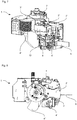
- FIG. 7 and 8 show a first preferred embodiment of the present invention. This first preferred embodiment has, with the exception of the differences described below, an identical embodiment to the first non-inventive embodiment.
- the device carrier 2 'in this fourth preferred embodiment has two interfaces 3, 3 ", which are each designed to receive and supply energy to a joining agent processing device 1.
- the first interface 3' is corresponding to the interface 3, which was described in the context of the first embodiment
- the interface 3 " is arranged in a clockwise direction around the coating unit interface 7 adjacent to the first interface 3 '.
- the interfaces 3, 3 " correlate to the design of the interface 3, as described in the context of the first preferred embodiment.
- the coating unit 1 of this fourth preferred embodiment is configured to provide the "hot melt adhesive joining technology" and the "laser joining technology".
- coating unit 1 has a joining agent processing device 4 'according to the embodiment described in the context of the first non-inventive embodiment, which is connected to the first interface 3', and a joining agent processing device 4 "according to the embodiment, as in the context of the third not inventive embodiment, which is connected to the second interface 3 ".
- the radiation outlet 12 and the melt adhesive outlet opening 8 of the devices 4 'and 4 " are preferably designed and oriented so that the conditioning of the edge band 6 takes place at the same or similar position for both technologies
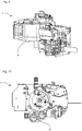
- Figs. 9 and 10 show a second preferred embodiment of the present invention, which corresponds to the first preferred embodiment except for the differences described below.
- the joining agent processing device 4 "of the second preferred embodiment is configured to provide the" hot gas joining technology.
- the joining agent processing device 4" is configured analogously to that of the second non-inventive embodiment.
- Third preferred embodiment Figs. 11 and 12 show a third preferred embodiment of the present invention. With the exception of the differences described below, the Embodiment of this third preferred embodiment of the first non-inventive embodiment.
- the coating unit 1 of this third embodiment is designed to provide all three joining technologies described above, more specifically, the "hot melt adhesive joining technology", the “laser joining technology” and the “hot gas joining technology”.
- the device carrier 2 "of this third preferred embodiment has a second and third interface for receiving and supplying power to a joining agent processing device, the interfaces being configured analogously to that of the first embodiment the three joining agent processing devices are arranged in a clockwise order around the coating unit interface 7, so that device 4 ', the "laser joining technology” device 4 "is arranged in front of the" hot-melt joining technology “device 4'” following the "hot-melt adhesive joining technology".
- the individual devices 4, 4 ", 4 '" are configured analogously to the corresponding devices in the embodiments described above n, more precisely, the hot melt outlet opening, the hot gas outlet and the radiation outlet are arranged in the same area, so that the preparation of the edge band takes place at the same or similar position.
Description
Die vorliegende Erfindung betrifft ein Beschichtungsaggregat zum Beschichten von insbesondere platten- oder leistenförmigen Werkstücken, die bevorzugt zumindest abschnittsweise aus Holz, Holzwerkstoffen, Kunststoff oder dergleichen bestehen, mit einem Beschichtungsmaterial.The present invention relates to a coating unit for coating in particular plate- or strip-shaped workpieces, which are preferably at least partially made of wood, wood materials, plastic or the like, with a coating material.
Im Bereich der Möbel- und Bauelementeindustrie müssen häufig Werkstücke im Bereich ihrer Schmal- oder Breitflächen mit einem Beschichtungsmaterial versehen werden, wenn die Werkstücke beispielsweise aus Holzwerkstoffen wie MDF, Spannplatte oder dergleichen bestehen. Meist werden die Beschichtungsmaterialien mit den Werkstückoberflächen verleimt, wobei sich weitere Fügetechniken entwickelt haben.In the field of furniture and component industry often workpieces must be provided in the region of their narrow or wide surfaces with a coating material, if the workpieces, for example, made of wood materials such as MDF, clamping plate or the like. Most of the coating materials are glued to the workpiece surfaces, with further joining techniques have developed.
Eine verwendete Fügetechnik basiert auf dem Einsatz eines Schmelzklebers, bei der eine Aufschmelzeinheit einen Klebstoff aufschmilzt und im Allgemeinen mittels Leimauftragssystemen in Form von Walzen oder Düsen auf das Beschichtungsmaterial oder auf die zu beschichtende Werkstückoberfläche aufträgt. Diese Fügetechnik ist dabei vergleichsweise kostengünstig, führt jedoch zu einer sichtbaren Leimfuge, die in gewissen Anwendungsbereichen aus ästhetischen Gründen unerwünscht ist.A joining technique used is based on the use of a hotmelt adhesive, in which a melting unit melts an adhesive and generally by means of glue application systems in the form of rollers or nozzles on the coating material or on the workpiece surface to be coated. This joining technique is comparatively inexpensive, but leads to a visible glue joint, which is undesirable in certain applications for aesthetic reasons.
Neben der konventionellen Schmelzkleber-Fügetechnik ist die sogenannte Nullfugen-Fügetechnik bekannt. Bei dieser Nullfugentechnik wird die zu verklebende Fläche des Beschichtungsmaterials beziehungsweise die zu beschichtende Werkstückoberfläche mit einer Funktionsschicht versehen, die durch Energieeintrag haftende Eigenschaften entwickelt. Dabei wird die Funktionsschicht im Allgemeinen durch einen Laserstrahl, ein heißes Gas oder mittels sonstiger Strahlungsenergie aktiviert und im Anschluss daran wird das Beschichtungsmaterial an die zu beschichtende Werkstückfläche gefügt. Im Vergleich zur Schmelzkleber-Fügetechnologie weist die Nullfugentechnik normalerweise höhere Fertigungskosten auf, resultiert jedoch in einer sehr hochwertigen Beschichtung mit einer deutlich höheren Haftkraft, einer verbesserten Feuchtebeständigkeit und einer optischen Nullfuge zwischen Kante und Platte.In addition to the conventional hot-melt adhesive joining technology, the so-called zero-joint joining technique is known. In the case of this zero-joint technique, the surface of the coating material to be bonded or the workpiece surface to be coated is provided with a functional layer which develops properties that adhere to it due to energy input. In this case, the functional layer is generally activated by a laser beam, a hot gas or by means of other radiation energy, and subsequently the coating material is joined to the workpiece surface to be coated. Compared to hot-melt adhesive joining technology, the zero-joint technique usually has higher production costs, but results in a very high-quality coating with a significantly higher adhesive force, improved moisture resistance and an optical zero joint between edge and panel.
Ferner ist die
Als weiteres Dokument ist die
Die
Die aus dem Stand der Technik bekannten Aggregate und Vorrichtungen weisen jedoch den Nachteil auf, dass dem Anwender auf einer Maschine lediglich eine Fügetechnologie, zum Beispiel die Schmelzklebertechnologie oder die Nullfugentechnologie, bereitgestellt werden kann. Dabei ist die Schmelzklebertechnologie nach wie vor das kostengünstigste Beschichtungsverfahren, wobei die Nullfugentechnologie höchste Qualitätsanforderung erfüllt. Um eine hohe Bearbeitungsvielfalt zu ermöglichen, ist es heutzutage daher erforderlich, zwei Maschinen, nämlich eine für die konventionelle Schmelzklebertechnologien und eine weitere für die neue Nullfugentechnologie vorzusehen.However, the known from the prior art units and devices have the disadvantage that the user on a machine only a joining technology, for example, the hot melt adhesive technology or the zero-joint technology, can be provided. Here, the hot melt adhesive technology is still the most cost-effective coating process, with the zero-joint technology meets the highest quality requirements. To enable a high variety of processing, it is therefore necessary today to provide two machines, namely one for the conventional hot melt adhesive technologies and another for the new zero joint technology.
Es ist daher Aufgabe der vorliegenden Erfindung, ein flexibles Beschichtungsaggregat bereitzustellen, mit dem verschiedene Beschichtungstechnologien umgesetzt werden können.It is therefore an object of the present invention to provide a flexible coating unit with which various coating technologies can be implemented.
Die Lösung der Aufgabe erfolgt durch das Aggregat des Patentanspruchs 1. Bevorzugte Ausgestaltungen ergeben sich aus den Unteransprüchen.The object is achieved by the unit of
Der Erfindung liegt der Gedanke zugrunde, dass die Bereitstellung von verschiedenen Beschichtungstechnologien auf einem Beschichtungsaggregat auf einfache, kostengünstige und platzsparende Weise dann möglich ist, wenn eine technologiespezifische Einrichtung einwechselbar ausgestaltet ist, und jene, die für alle Fügetechnologien erforderlich ist, bereits an dem Aggregat vorgesehen ist. So lässt sich beispielsweise zum Fügen eines Beschichtungsmaterials mittels Schmelzklebetechnologie eine schmelzkleberspezifische Fügemittelaufbereitungseinrichtung bereitstellen, die bei Forderung eines Fügens mittels Nullfugentechnologie durch eine beispielsweise laserstrahlspezifische Fügemittelaufbereitungseinrichtung ausgetauscht werden kann.The invention is based on the idea that the provision of different coating technologies on a coating unit in a simple, cost-effective and space-saving manner is possible when a technology-specific device is designed einwechselbar, and those that are required for all joining technologies, already provided on the unit is. Thus, for example, for joining a coating material by means of hot melt adhesive technology, it is possible to provide a hot melt adhesive-specific joining agent processing device which, when a joining by means of zero-joint technology is required, requires For example, a laser beam-specific joining agent processing device can be exchanged.
Die verschiedenen Fügetechnologien basieren auf verschiedenen Energieformen, sodass beispielsweise die Schmelzklebertechnologie auf thermischer Energie basiert, die zum Aufschmelzen eines Schmelzklebers erforderlich ist, während die Nullfugentechnologie beispielsweise auf elektromagnetischer Energie basiert, die zum Aktivieren einer Funktionsschicht mittels elektromagnetischer Strahlung erforderlich ist.The different joining technologies are based on different forms of energy, for example, the hot melt adhesive technology based on thermal energy, which is required for melting a hot melt adhesive, while the zero-joint technology, for example, based on electromagnetic energy, which is required for activating a functional layer by means of electromagnetic radiation.
Erfindungsgemäß wird das im Stand der Technik vorhandene Problem daher dadurch gelöst, dass ein Beschichtungsaggregat bereitgestellt wird, welches eine Schnittstelle zur Aufnahme und Energieversorgung einer einwechselbaren Fügemittelaufbereitungseinrichtung und eine an diese Schnittstelle ankoppelbare einwechselbare Fügemittelaufbereitungseinrichtung aufweist. Dabei umfasst die Fügemittelaufbereitungseinrichtung eine Energiewandlungseinrichtung zum Wandeln der über die Schnittstelle bereitgestellten Energie zur Aufbereitung eines Fügemittels zum Fügen des Beschichtungsmaterials an die zu beschichtende Oberfläche des Werkstücks, wobei das Aggregat eine zweite Schnittstelle zur Aufnahme und Energieversorgung einer einwechselbaren Fügemittelaufbereitungseinrichtung aufweist.According to the invention, the problem existing in the prior art is therefore solved by providing a coating unit which has an interface for receiving and supplying energy to a replaceable joining agent processing device and a replaceable joining agent processing device which can be coupled to this interface. In this case, the joining agent processing device comprises an energy conversion device for converting the energy provided via the interface for processing a joining agent for joining the coating material to the surface of the workpiece to be coated, the aggregate having a second interface for receiving and supplying energy to a disposable joining agent processing device.
Das Fügemittel kann beispielsweise ein Schmelzkleber sein, wobei die Aufbereitung beispielsweise dann auf ein Aufschmelzen des Schmelzklebers abzielt. Ebenso kann das Fügemittel eine Funktionsschicht sein, die beispielsweise mittels eines Laserstrahls oder eines Heißgases aktiviert wird, also zum Fügen des Beschichtungsmaterials aufbereitet wird.The joining agent may be, for example, a hotmelt adhesive, wherein the treatment, for example, then aims at melting the hotmelt adhesive. Likewise, the joining agent may be a functional layer which is activated, for example, by means of a laser beam or a hot gas, that is to say it is prepared for joining the coating material.
Die Schnittstelle stellt dabei bevorzugt elektrische Energie bereit, welche über eine Energiewandlungseinrichtung, die auf der jeweiligen Fügemittelaufbereitungseinrichtung selbst vorgesehen ist, in eine für die Fügetechnologie erforderliche Energieform gewandelt wird. So wird beispielsweise die elektrische Energie, welche über die Schnittstelle der einwechselbaren Fügemittelaufbereitungseinrichtung zugeführt wird, mit der Energiewandlungseinrichtung für die laserbasierte Nullfugentechnologie, die auf der Fügemittelaufbereitungseinrichtung selbst vorgesehen ist, in elektromagnetische Energie, nämlich einen Laserstrahl, zum Aktivieren einer Funktionsschicht gewandelt. Die Energiewandlungseinrichtung eines Schmelzklebeaggregats kann hingegen beispielsweise die elektrische Energie, welche über die Schnittstelle bereitgestellt wird, auf der Fügemittelaufbereitungseinrichtung selbst, in thermische Energie zum Schmelzen eines Klebstoffs wandeln.In this case, the interface preferably provides electrical energy, which is converted into an energy form required for the joining technology by means of an energy conversion device which is provided on the respective joining agent processing device itself. Thus, for example, the electrical energy which is supplied via the interface of the exchangeable joining agent processing device to the energy conversion device for the laser-based zero-joint technology, which is provided on the joining agent processing device itself, is converted into electromagnetic energy, namely a laser beam, for activating a functional layer. By contrast, the energy conversion device of a hot-melt adhesive unit, for example, can convert the electrical energy which is provided via the interface on the joining agent processing device itself into thermal energy for melting an adhesive.
Das erfindungsgemäße Beschichtungsaggregat ermöglicht somit ein Bereitstellen von verschiedenen Fügetechnologien auf einem Aggregat. Dies ermöglicht eine hohe Bearbeitungsvariabilität mit insgesamt entsprechend geringen Systemkosten. Ferner führt die erfindungsgemäße Ausgestaltung zu einem schlanken und kompakten System und insbesondere einer einfach ausgestalteten Schnittstelle, da die für die jeweiligen Fügetechnologien spezifischen Einrichtungen auf den entsprechenden Fügemittelaufbereitungseinrichtungen selbst vorgesehen sind. Somit ist es beispielsweise nicht erforderlich, dass all die unterschiedlichen Energieformen, die für die verschiedenen Fügetechnologien erforderlich sind, über die Schnittstelle bereitgestellt werden müssen. Ferner ermöglicht das erfindungsgemäße Beschichtungsaggregat eine beliebige Erweiterbarkeit, da die universell ausgestaltete Schnittstelle auch die Aufnahme von Fügemittelaufbereitungseinrichtungen mit erst in Zukunft entwickelten Fügetechnologien ermöglicht.The coating unit according to the invention thus makes it possible to provide various joining technologies on an aggregate. This allows a high processing variability with a total correspondingly low system costs. Furthermore, the inventive design leads to a slim and compact system and in particular a simply designed interface, since the specific for the respective joining technologies facilities are provided on the corresponding joining agent processing facilities themselves. Thus, for example, it is not necessary that all the different forms of energy required for the various joining technologies be provided via the interface. Furthermore, the coating unit according to the invention allows any expandability, since the universally configured interface also allows the inclusion of joining agent processing facilities with joining technologies developed in the future.
Ferner können durch das Vorsehen einer zweiten Schnittstelle gleichzeitig zwei verschiedene Fügetechnologien auf einem Aggregat ohne Rüstvorgang bereitgestellt werden. Dies ermöglicht eine erhöhte Bearbeitungseffizienz und damit geringere Stückkosten. Ferner ermöglicht die zweite Schnittstelle eine höhere Maschinenstandzeit, da beispielsweise bei einem Defekt der ersten Schnittstelle, die erste Fügemittelaufbereitungseinrichtung auf die zweite Schnittstelle umgerüstet werden kann und es somit nicht zu einem Maschinenausfall kommt.Furthermore, the provision of a second interface simultaneously two different joining technologies can be provided on an aggregate without setup process. This allows an increased processing efficiency and thus lower unit costs. Furthermore, the second interface allows a higher machine downtime, since, for example, in the event of a defect of the first interface, the first joining agent processing device can be converted to the second interface and thus no machine failure occurs.
In einer bevorzugten Ausgestaltung kann das Beschichtungsaggregat auch eine zweite mit der ersten und/oder zweiten Schnittstelle verbindbare einwechselbare Fügemittelaufbereitungseinrichtung aufweisen, die eine Energiewandlungseinrichtung zum Wandeln der über die Schnittstelle bereitgestellten Energie zur Aufbereitung eines Fügemittels zum Fügen des Beschichtungsmaterials an die zu beschichtende Oberfläche des Werkstücks umfasst. Dies führt zu dem Vorteil, dass verschiedene Fügetechnologien auf einer Maschine bereitgestellt werden können und/oder eine Fügemittelaufbereitungseinrichtung gewartet werden kann, während eine entsprechende in die Maschine einwechselbar ist. Dies ermöglicht eine erhöhte Bearbeitungsvariabilität beziehungsweise eine erhöhte Maschinenstandzeit.In a preferred embodiment, the coating unit can also have a second connectable joining agent processing device which can be connected to the first and / or second interface and which comprises an energy conversion device for converting the energy provided via the interface for processing a joining agent for joining the coating material to the surface of the workpiece to be coated , This leads to the advantage that different joining technologies can be provided on a machine and / or a joining agent processing device can be maintained while a corresponding one can be exchanged into the machine. This allows increased processing variability or increased machine life.
Bevorzugt weist eine Fügemittelaufbereitungseinrichtung ein Haftmittelbehältnis zur Aufnahme eines Haftmittels und eine Auftragseinrichtung zum Auftragen des Haftmittels auf das Beschichtungsmaterial und/oder die zu beschichtende Oberfläche des Werkstücks auf. Ferner ist das Bearbeitungsaggregat bevorzugt eingerichtet, das Haftmittel vor dem Auftragen mittels der Energiewandlungseinrichtung der Fügemittelaufbereitungseinrichtung zu aktivieren. Erfindungsgemäß wird unter einer Aktivierung eines Fügemittels ein Prozess verstanden, der dazu führt, dass das Fügemittel haftende Eigenschaften entwickelt. Ein erfindungsgemäßes Aktivieren kann somit beispielsweise das Aufschmelzen bzw. Verflüssigen eines Klebstoffs und/oder das Anregen einer Funktionsschicht mit einem Laserstrahl sein. Diese Ausgestaltung des Fügeaggregats ermöglicht dabei das Bereitstellen der kostengünstig einsetzbaren Schmelzklebetechnologie auf dem Beschichtungsaggregat.Preferably, a joining agent processing device has an adhesive container for receiving an adhesive and an application device for applying the adhesive to the coating material and / or the surface of the workpiece to be coated. Furthermore, the processing unit is preferably configured to activate the adhesive before application by means of the energy conversion device of the joining agent processing device. According to the invention, an activation of a joining agent is understood to mean a process which results in the joining agent developing adhering properties. One Activation according to the invention can thus be, for example, the melting or liquefying of an adhesive and / or the exciting of a functional layer with a laser beam. This embodiment of the joining unit makes it possible to provide the low-cost melt adhesive technology on the coating unit.
Eine Fügemittelaufbereitungseinrichtung kann eingerichtet sein, eine durch Energieeintrag aktivierbare Funktionsschicht zum Fügen des Beschichtungsmaterials an die zu beschichtende Oberfläche des Werkstücks zu aktivieren. Eine so ausgestaltete Fügemittelaufbereitungseinrichtung ermöglicht dabei das Bereitstellen der zuvor beschriebenen Nullfugenfügetechnologie auf dem Beschichtungsaggregat. Dabei wird die durch Energieeintrag aktivierbare Funktionsschicht entweder dem Fügebereich zwischen Beschichtungsmaterial und zu beschichtender Oberfläche des Werkstücks zugeführt oder ist auf der Oberfläche des zu beschichtenden Werkstücks beziehungsweise auf dem Beschichtungsmaterial vorgesehen.A joining agent processing device can be set up to activate a functional layer activatable by energy input for joining the coating material to the surface of the workpiece to be coated. A joining agent processing device configured in this way makes it possible to provide the previously described zero-joint joining technology on the coating unit. The activatable by energy input functional layer is either supplied to the joining region between the coating material and the surface to be coated of the workpiece or is provided on the surface of the workpiece to be coated or on the coating material.
Gemäß einer Ausführungsform weist die Energiewandlungseinrichtung der ersten Fügemittelaufbereitungseinrichtung und/oder ggf. der zweiten Fügemittelaufbereitungseinrichtung mindestens eine Laserdiode zur Erzeugung eines Laserstrahls auf. Bevorzugt weist die Energiewandlungseinrichtung ferner eine Strahlführungs-und/oder Strahlformungseinrichtung für den Laserstrahl auf. Die Laserdiode zur Erzeugung eines Laserstrahls ermöglicht dabei eine effektive Aktivierung eines Schmelzklebers und/oder einer Funktionsschicht mittels eines Laserstrahls. Die erfindungsgemäße Ausgestaltung, bei welcher die Laserdiode auf der Fügemittelaufbereitungseinrichtung selbst vorgesehen ist, umgeht ferner das Erfordernis, aufwendige und kostenintensive Strahlführungssysteme sowie eine komplexe Schnittstelle vorzusehen, um den Laserstrahl dem Aktivierungsbereich zuzuführen.According to one embodiment, the energy conversion device of the first joining agent processing device and / or optionally of the second joining agent processing device has at least one laser diode for generating a laser beam. The energy conversion device preferably also has a beam guidance and / or beam shaping device for the laser beam. The laser diode for generating a laser beam thereby enables effective activation of a hotmelt adhesive and / or a functional layer by means of a laser beam. The embodiment according to the invention, in which the laser diode is provided on the joining agent processing device itself, also obviates the need to provide complex and costly beam guiding systems as well as a complex interface in order to supply the laser beam to the activation region.
Gemäß einer Ausführungsform weist die Energiewandlungseinrichtung der ersten Fügemittelaufbereitungseinrichtung und/oder zweiten Fügemittelaufbereitungseinrichtung ein Heizsystem zur Erzeugung eines Heißgases auf. Bevorzugt weist die Energiewandlungseinrichtung ferner eine Düseneinrichtung zum Applizieren des Heißgases auf beispielsweise das Beschichtungsmaterial und/oder die zu beschichtende Oberfläche auf. Ebenso kann das Heißgas verwendet werden, um das Beschichtungsmaterial und/oder die zu beschichtende Werkstückoberfläche vorzuwärmen. Das Heißgas stellt dabei eine vergleichsweise kostengünstige Energieform dar. Die Energiewandlungseinrichtung kann dabei Anschlüsse für die Gasversorgung aufweisen, die beispielsweise auf deren Oberseite angeordnet sind. Es ist jedoch auch denkbar, dass die Gasversorgung über die Schnittstelle des Aggregats stattfindet.According to one embodiment, the energy conversion device of the first joining agent processing device and / or second joining agent processing device has a heating system for generating a hot gas. The energy conversion device preferably also has a nozzle device for applying the hot gas to, for example, the coating material and / or the surface to be coated. Likewise, the hot gas may be used to preheat the coating material and / or the workpiece surface to be coated. In this case, the hot gas represents a comparatively inexpensive form of energy. The energy conversion device can have connections for the gas supply, which are arranged, for example, on their upper side. However, it is also conceivable that the gas supply takes place via the interface of the unit.
Gemäß einer weiteren Ausführungsform weist das Beschichtungsaggregat ein Andrückelement zum Andrücken des Beschichtungsmaterials an die zu beschichtende Oberfläche des Werkstücks auf. Solch eine Ausgestaltung führt zu einem Beschichtungsaggregat mit einer geringen Komplexität und einer erhöhten energetischen Effizienz, da das Andrückelement in unmittelbarer Nähe der Energiewandlungseinrichtung der jeweiligen Fügemittelaufbereitungseinrichtung vorgesehen ist. Somit kann das Beschichtungsmaterial direkt angrenzend an den Ort, an welchem ein Fügemittel, zum Beispiel ein Schmelzkleber, auf dem Beschichtungsmaterial vorgesehen wird, oder eine Funktionsschicht aktiviert wird, mit der zu beschichtenden Oberfläche gefügt werden. Auf diese Weise kann ein Abkühlen bzw. Antrocknen des Fügemittels vermieden oder zumindest minimiert werden.According to a further embodiment, the coating unit has a pressure element for pressing the coating material against the surface of the workpiece to be coated. Such an embodiment results in a coating aggregate with a low complexity and an increased energy efficiency, since the pressing element is provided in the immediate vicinity of the energy conversion device of the respective joining agent processing device. Thus, the coating material may be directly joined to the surface to be coated adjacent to the location where a joining agent, for example, a hot melt adhesive, is provided on the coating material or a functional layer is activated. In this way, cooling or drying of the joining agent can be avoided or at least minimized.
Bevorzugt weist das Beschichtungsaggregat eine Aggregatschnittstelle zum einwechselbaren Ankoppeln des Aggregats an eine Beschichtungsmaschine auf. Solch eine Ausgestaltung des Aggregats ermöglicht dabei, dass dieses beispielsweise mit bestehenden Beschichtungsvorrichtungen verbunden werden kann. Ferner wird eine leichte Aggregatswartung und Austauschbarkeit gewährleistet.The coating unit preferably has an aggregate interface for interchangeable coupling of the unit to a coating machine. Such a Design of the unit allows this, for example, can be connected to existing coating devices. Furthermore, a slight aggregate maintenance and interchangeability is ensured.
Ferner stellt die vorliegende Erfindung eine Beschichtungsvorrichtung mit einem zuvor beschriebenen Beschichtungsaggregat bereit. Die Vorrichtung weist dabei ferner eine Zuführeinrichtung zum Zuführen eines Beschichtungsmaterials zu der zu beschichtenden Oberfläche des Werkstücks, ein Andrückelement zum Andrücken des Beschichtungsmaterials an die zu beschichtenden Oberfläche des Werkstücks und eine Fördereinrichtung zum Herbeiführen einer Relativbewegung zwischen dem Andrückelement und der zu beschichtenden Oberfläche des Werkstücks auf. Das Andrückelement der Vorrichtung kann dabei auch an dem Beschichtungsaggregat vorgesehen sein.Further, the present invention provides a coating apparatus having a coating unit as described above. The apparatus further comprises a feeding device for feeding a coating material to the surface of the workpiece to be coated, a pressing element for pressing the coating material against the surface of the workpiece to be coated and a conveying device for causing a relative movement between the pressing element and the surface of the workpiece to be coated , The pressing element of the device can also be provided on the coating unit.
Gemäß einer Ausführungsform weist die Vorrichtung eine Wechseleinrichtung zum Rüsten des Beschichtungsaggregats auf die erste und/oder zweite Fügemittelaufbereitungseinrichtung und/oder zum Umrüsten der Vorrichtung auf eine andere Fügemittelaufbereitungseinrichtung auf. Es wird darauf hingewiesen, dass die Wechseleinrichtung auch Teil des Beschichtungsaggregats sein kann. Mittels der Wechseleinrichtung lässt sich der Rüst- beziehungsweise Umrüstvorgang automatisieren und damit die Effizienz der Beschichtungsvorrichtung bzw. des Beschichtungsaggregats steigern. Dies führt zu geringeren Fertigungszeiten und damit einem erhöhten Output, was wiederum in geringeren Stückkosten resultiert.According to one embodiment, the device has a changing device for equipping the coating unit to the first and / or second joining agent processing device and / or for converting the device to another joining agent processing device. It should be noted that the changing device can also be part of the coating unit. By means of the changing device, the set-up or conversion process can be automated and thus increase the efficiency of the coating device or of the coating unit. This leads to lower production times and thus increased output, which in turn results in lower unit costs.
-
Fig. 1 zeigt eine Seitenansicht des Beschichtungsaggregats einer ersten nicht erfindungsgemäßen Ausführungsform.Fig. 1 shows a side view of the coating unit of a first non-inventive embodiment. -
Fig. 2 zeigt eine Draufsicht des Beschichtungsaggregats der ersten Ausführungsform.Fig. 2 shows a plan view of the coating unit of the first embodiment. -
Fig. 3 zeigt eine Seitenansicht des Beschichtungsaggregats einer zweiten nicht erfindungsgemäßen Ausführungsform.Fig. 3 shows a side view of the coating unit of a second non-inventive embodiment. -
Fig. 4 zeigt eine Draufsicht des Beschichtungsaggregats der zweiten Ausführungsform.Fig. 4 shows a plan view of the coating unit of the second embodiment. -
Fig. 5 zeigt eine Seitenansicht des Beschichtungsaggregats einer dritten nicht erfindungsgemäßen Ausführungsform.Fig. 5 shows a side view of the coating unit of a third non-inventive embodiment. -
Fig. 6 zeigt eine Draufsicht des Beschichtungsaggregats der dritten Ausführungsform.Fig. 6 shows a plan view of the coating unit of the third embodiment. -
Fig. 7 zeigt eine Seitenansicht des Beschichtungsaggregats einer ersten Ausführungsform der vorliegenden Erfindung.Fig. 7 shows a side view of the coating unit of a first embodiment of the present invention. -
Fig. 8 zeigt eine Draufsicht des Beschichtungsaggregats der ersten Ausführungsform der vorliegenden Erfindung.Fig. 8 Fig. 10 is a plan view of the coating apparatus of the first embodiment of the present invention. -
Fig. 9 zeigt eine Seitenansicht des Beschichtungsaggregats einer zweiten Ausführungsform der vorliegenden Erfindung.Fig. 9 shows a side view of the coating unit of a second embodiment of the present invention. -
Fig. 10 zeigt eine Draufsicht des Beschichtungsaggregats der zweiten Ausführungsform der vorliegenden Erfindung.Fig. 10 shows a plan view of the coating unit of the second embodiment of the present invention. -
Fig. 11 zeigt eine Seitenansicht des Beschichtungsaggregats einer dritten Ausführungsform der vorliegenden Erfindung.Fig. 11 shows a side view of the coating unit of a third embodiment of the present invention. -
Fig. 12 zeigt eine Draufsicht des Beschichtungsaggregats der dritten Ausführungsform der vorliegenden Erfindung.Fig. 12 Fig. 10 is a plan view of the coating apparatus of the third embodiment of the present invention.
Detaillierte Beschreibung der Ausführungsformen Ausführungsformen werden nachfolgend unter Bezugnahme auf die begleitenden Zeichnungen beschrieben. Weitere Varianten und Modifikationen können jeweils miteinander kombiniert werden, um weitere Ausführungsformen auszubilden.DETAILED DESCRIPTION OF THE EMBODIMENTS Embodiments will be described below with reference to the accompanying drawings. Other variants and modifications can each be combined with each other to form further embodiments.
Die nachfolgend beschriebenen Ausführungsformen des Beschichtungsaggregats dienen dem Beschichten von insbesondere Werkstückschmalseiten mit einem Beschichtungsmaterial. Die Werkstücke bestehen dabei zumindest abschnittsweise aus Holz, Holzwerkstoffen, Kunststoff oder dergleichen, wie sie beispielsweise im Bereich der Möbel- und Bauelementeindustrie zum Einsatz kommen. Dabei kann es sich beispielsweise um Massivholz- oder Spannplatten, Leichtbauplatten, Sandwichplatten, oder dergleichen handeln.The embodiments of the coating unit described below serve for coating in particular workpiece narrow sides with a coating material. The workpieces are at least partially made of wood, wood materials, plastic or the like, as used for example in the field of furniture and component industry. These may be, for example, solid wood or chipboard, lightweight panels, sandwich panels, or the like.
Das Beschichtungsmaterial ist bevorzugt ein Kantenband, welches aus unterschiedlichen Materialien, wie beispielsweise Kunststofffurnier, Papier, Pappe, Metall etc. und vielfältigen Kombinationen hiervon, bestehen kann. Dabei wird das Beschichtungsmaterial bevorzugt in einer Rollenform vorgesehen, kann aber beispielsweise auch in Form von Einzelabschnitten bereitgestellt werden. Ferner kann das Beschichtungsmaterial eine Funktionsschicht aufweisen, die durch Energieeintrag (beispielsweise Erwärmung oder Laserstrahlung) haftende Eigenschaften entfaltet, sodass das Beschichtungsmaterial an ein Werkstück über die Funktionsschicht gefügt werden kann. Dabei kann die Funktionsschicht Mittel zur Erhöhung der Wärmeleitfähigkeit, wie beispielsweise Polyolefine und/oder Metallpartikel aufweisen. Ferner kann die Funktionsschicht Absorber für Laserlicht oder andere Strahlungsquellen aufweisen. Alternativ kann die Funktionsschicht auch separat zwischen Beschichtungsmaterial und Werkstück zugeführt werden, oder bereits auf der zu beschichtenden Oberfläche des Werkstücks vorgesehen sein.The coating material is preferably an edge band which may be made of different materials such as plastic veneer, paper, paperboard, metal, etc., and various combinations thereof. In this case, the coating material is preferably provided in a roll form, but may for example also be provided in the form of individual sections. Furthermore, the coating material may have a functional layer which unfolds adhesive properties due to energy input (for example heating or laser radiation), so that the coating material can be joined to a workpiece via the functional layer. In this case, the functional layer may comprise means for increasing the thermal conductivity, such as polyolefins and / or metal particles. Furthermore, the functional layer can have absorbers for laser light or other radiation sources. Alternatively, the functional layer may also be supplied separately between the coating material and the workpiece, or may already be provided on the surface of the workpiece to be coated.
Im Folgenden wird eine erste Ausführungsform eines Beschichtungsaggregats 1 unter Bezugnahme auf die
Die Beschichtungsaggregatschnittstelle 7 ermöglicht eine Ankopplung des Beschichtungsaggregats 1 an eine nicht gezeigte Beschichtungsmaschine. Die Beschichtungsaggregatschnittstelle 7 weist dabei bevorzugt Anschlüsse zur elektrischen Energieversorgung des Aggregats 1 auf. Ebenso ist es möglich, dass die Schnittstelle 7 Anschlüsse zur Versorgung des Beschichtungsaggregat 1 mit Druckluft, Kühlmittel etc. und/oder Anschlüsse zur Steuerung/Regelung des Beschichtungsaggregats 1 umfasst.The
Dabei ist in der vorliegenden Ausführungsform das Beschichtungsaggregat 1 um die Beschichtungsaggregatschnittstelle 7 herum und in der Höhenstreckungsrichtung h des Aggregats 1 unterhalb der Schnittstelle 7 aufgebaut.Here, in the present embodiment, the
Der Einrichtungsträger 2 erstreckt sich in dieser bevorzugten Ausführungsform entlang etwa 90 Grad um die Beschichtungsaggregatschnittstelle 7 und weist eine radiale Ausdehnung auf, die in etwa zwei Mal dem maximalen Durchmesser der Beschichtungsaggregatschnittstelle 7 entspricht. Der Einrichtungsträger 2 weist ferner einen Kanteneinlauf 9 auf, der in dessen Umfangsausedehnung in dieser bevorzugten Ausführungsform in etwa auf der Mitte, in Höhenerstreckungsrichtung h am unteren Ende sowie um äußeren Umfang des Trägers 2 angeordnet ist. Ferner umfasst der Einrichtungsträger 2 bevorzugt zwei Andrückrollen 5, die in Höhenstreckungsrichtung h am unteren Ende des Einrichtungsträger 2 und in radialer Richtung im Bereich der Beschichtungsaggregatschnittstelle 7 angeordnet sind. Bevorzugt sind die Andrückrollen 5 dabei auf etwa gleicher Höhe wie der Kanteneinlauf 9 angeordnet. Dabei sind auch nur eine Andrückrolle oder mehr als zwei Andrückrollen denkbar. Ebenso ist beispielsweise ein Andrückschuh oder ein sonstiges Andrückelement vorstellbar, mit dem das Beschichtungsmaterial 6 an die zu beschichtende Werkstückoberfläche angedrückt werden kann. Auch ein verstellbares und/oder regelbares Andrückelement, mit dem der Andrückdruck anpassbar ist, wäre hier möglich.The
Darüber hinaus weist der Einrichtungsträger 2 die Schnittstelle 3 zur Aufnahme und Energieversorgung der Fügemittelaufbereitungseinrichtung 4 auf. Dabei ist die Schnittstelle 3 bevorzugt außerhalb des Bereichs der Beschichtungsaggregatschnittstelle 7 vorgesehen, sodass die An- bzw. Abkopplung der Einrichtung 4 nicht durch diese behindert wird. Bevorzugt ist die Schnittstelle 3 auf etwa der Hälfte der radialen Ausdehnung des Trägers 2 und/oder in Umfangserstreckungsrichtung des Trägers 2 auf Höhe des Kanteneinlaufs 9 angeordnet. Die Schnittstelle 3 ist dabei so ausgestaltet, dass die Fügemittelaufbereitungseinrichtung 4 in diese einwechselbar und damit an das Beschichtungsaggregat 1 ankoppelbar ist. Diese Ankopplung erfolgt dabei bevorzugt über eine Relativverschiebung von Schnittstelle 3 und Einrichtung 4, sodass die Einrichtung 4 durch Verschieben in die Höhenerstreckungsrichtung h des Beschichtungsaggregats 1 in die Schnittstelle 3 eingewechselt werden kann. Die Abkopplung der Fügemittelaufbereitungseinrichtung 4 von der Schnittstelle 3 erfolgt bevorzugt durch eine entsprechende Relativverschiebung der Teile in die entgegengesetzte Richtung. Die Schnittstelle 3 weist bevorzugt Anschlüsse zur elektrischen Energieversorgung einer angekoppelten Fügemittelaufbereitungseinrichtung 4 auf. Auch kann diese Anschlüsse zur Druckluft- bzw. Heißluftversorgung oder Versorgung einer angekoppelten Einrichtung 4 mit elektromagnetischer Energie, Laserstrahlung oder sonstigen Energieformen umfassen. Auch Anschlüsse zur Steuerung/Regelung der Einrichtung 4 oder sonstige Anschlüsse sind denkbar. Bevorzugt sind die Anschlüsse der Schnittstelle 3 dabei nicht einrichtungsspezifisch ausgestaltet, sondern für jegliche Fügemittelaufbereitungseinrichtungen 4, die zur Ankopplung an die Schnittstelle 3 geeignet und insbesondere ausgestaltet sind, verwendbar.In addition, the
Die einwechselbar Fügemittelaufbereitungseinrichtung 4, die über die Schnittstelle 3 an das Beschichtungsaggregat 1 an- bzw. abkoppelbar ist, dient dem Aufbereiten eines Fügemittels, welches zum Fügen des Beschichtungsmaterials 6 an die zu beschichtende Oberfläche des Werkstücks erforderlich ist. Dabei weist die Einrichtung 4 eine Längsausdehnung 1 auf, die in der gleichen Größenordnung liegt, wie die radiale Ausdehnung r des Trägers 2. Die Aufbereitung des Fügemittels erfolgt dabei über eine nicht gezeigte Energiewandlungseinrichtung, welche die über die Schnittstelle 3 bereitgestellte elektrische Energie in eine Energieform wandelt, die zur Aufbereitung des Fügemittels erforderlich ist. In dieser ersten bevorzugten Ausführungsform ist die Einrichtung 4 ausgestaltet, die sogenannte "Schmelzkleber-Fügetechnologie" bereitzustellen. Dabei weist die Energiewandlungseinrichtung der Fügemittelaufbereitungseinrichtung 4 eine nicht gezeigte Heizeinrichtung zum Wandeln der elektrischen Energie, die über die Schnittstelle 3 bereitgestellt wird, in thermische Energie auf, um einen Schmelzklebers zu verflüssigen. Die Fügemittelaufbereitungseinrichtung 4 weist ferner eine Schmelzkleberaustrittsöffnung 8 auf, die im angekoppelten Zustand der Einrichtung 4 in etwa auf Höhe der Andrückrollen 5 und des Kanteneinlaufs 9 des Beschichtungsaggregats 1 angeordnet ist. Dabei ist die Öffnung 8 so ausgestaltet und orientiert, dass über diese der verflüssigte Schmelzkleber auf ein Kantenband 6, welches dem Beschichtungsaggregat 1 über den Kanteneinlauf 9 zugeführt wird, aufgetragen werden kann. Ebenso ist hier eine Ausgestaltung und Orientierung der Schmelzkleberaustrittsöffnung denkbar, mit welcher der Schmelzkleber auf die zu beschichtende Oberfläche des Werkstücks auftragbar ist.The exchangeable joining
Die zweite Ausführungsform unterscheidet sich von der ersten Ausführungsform dadurch, dass die Fügemittelaufbereitungseinrichtung 4 ausgestaltet ist, die "Heißgas-Fügetechnologie" bereitzustellen. Dafür weist die Einrichtung 4 zwei Gaszuführanschlüsse 10 auf, die in der vorliegenden Ausführungsform an der Oberseite vorgesehen sind. Hier sei darauf hingewiesen, dass diese Anschlüsse beliebig angeordnet werden können, oder auch eine Gaszufuhr über die Schnittstelle 3 des Einrichtungsträgers 2 denkbar ist. In dieser zweiten bevorzugten Ausführungsform weist die nicht gezeigte Energiewandlungseinrichtung der Fügemittelaufbereitungseinrichtung 4 ein Heizsystem auf, mit dem das über die Gaszuführanschlüsse 10 zugeführte Gas, erwärmt wird. Das Heizsystem der Energiewandlungseinrichtung wird dabei über die Schnittstelle 3 mit elektrischer Energie versorgt. Bei dem zugeführten Gas kann es sich um ein Gas mit einem Überdruck von insbesondere mehreren Bar gegenüber der Umgebung handeln. Ferner weist die Fügemittelaufbereitungseinrichtung 4 der zweiten Ausführungsform einen Heißgasaustritt 11 auf, der im angekoppelten Zustand der Einrichtung 4 in etwa auf Höhe der Andrückrollen 5 und des Kanteneinlaufs 9 angeordnet ist. Dabei ist der Heißgasaustritt 11 so ausgestaltet und orientiert, dass ein Kantenband 6, welches bevorzugt eine Funktionsschicht aufweist, die durch Energieeintrag haftende Eigenschaften entwickelt, mittels des Heizgases, welches aus dem Austritt 11 austritt, aufbereitet bzw. aktiviert werden kann. Der Heißgasaustritt 11 kann dabei auch so ausgestaltet und orientiert sein, dass mit diesem eine Funktionsschicht auf dem Werkstück und/oder eine dem Fügebereich separat zugeführte Funktionsschicht aufbereitet und/oder aktiviert werden kann.The second embodiment differs from the first embodiment in that the joining
Im Unterschied zu der ersten Ausführungsform, weist die dritte Ausführungsform eine Fügemittelaufbereitungseinrichtung 4 auf, die ausgestaltet ist, die "Laser-Fügetechnologie" bereitzustellen. Die Einrichtung 4 dieser dritten bevorzugten Ausführungsform weist dabei eine nicht gezeigte Energiewandlungseinrichtung auf, die eine Laserdiode umfasst. Mittels dieser Energiewandlungseinrichtung wird dabei die über die Schnittstelle 3 bereitgestellte Energie in elektromagnetische Strahlung in Form eines Laserstrahls gewandelt. Hier sei darauf hingewiesen, dass die Energiewandlungseinrichtung auch mehrere Laserdioden aufweisen kann. Ferner umfasst die Fügemittelaufbereitungseinrichtung 4 einen Strahlenaustritt 12, welcher im angekoppelten Zustand der Einrichtung 4 in etwa auf Höhe der Andrückrollen 5 sowie des Kanteneinlaufs 9 angeordnet ist. Der Strahlenaustritt 12 ist dabei so ausgestaltet und orientiert, das mit dem Laserstrahl, der aus diesem austritt, eine Funktionsschicht auf dem Kantenband 6, welches dem Beschichtungsaggregat 1 über den Kanteneinlauf 9 zugeführt wird, aufbereitet bzw. aktiviert werden kann. Auch eine Ausgestaltung und Orientierung zur Aktivierung einer Funktionsschicht auf einer zu beschichtenden Oberfläche und/oder einer Funktionsschicht die dem Fügebereich separat zugeführt wird ist denkbar.Unlike the first embodiment, the third embodiment has a joining
Darüber hinaus weist die Einrichtung 4 Kühlrippen 13 auf, die zur passiven Kühlung der Einrichtung 4 ausgestaltet sind. Hier sei darauf hingewiesen, dass auch eine aktive Kühlung der Einrichtung 4 über ein Kühlmittel denkbar ist. Dieses kann über Anschlüsse an der Einrichtung 4 und/oder aber auch über entsprechende Anschlüsse über die Schnittstelle 3 des Einrichtungsträgers 2 der Fügemittelaufbereitungseinrichtung 4 zugeführt werden. Erste bevorzugte Ausführungsform
Gemäß der ersten bevorzugten Ausführungsform werden auf dem Beschichtungsaggregat 1 zwei verschiedene Fügetechnologien bereitgestellt. Dabei weist der Einrichtungsträger 2' in dieser vierten bevorzugten Ausführungsform zwei Schnittstellen 3, 3" auf, die jeweils zur Aufnahme und Energieversorgung einer Fügemittelaufbereitungseinrichtung ausgestaltet sind. Die erste Schnittstelle 3' ist dabei entsprechend der Schnittstelle 3, welche im Rahmen der ersten Ausführungsform beschrieben wurde, angeordnet. Die Schnittstelle 3" ist im Uhrzeigersinn um die Beschichtungsaggregatschnittstelle 7 anschließend an die erste Schnittstelle 3' angeordnet. Die Schnittstellen 3, 3" entsprechen dabei der Ausgestaltung der Schnittstelle 3, wie sie im Rahmen der ersten bevorzugten Ausführungsform beschrieben wurde.According to the first preferred embodiment, two different joining technologies are provided on the
Das Beschichtungsaggregat 1 dieser vierten bevorzugten Ausführungsform ist ausgestaltet, die "Schmelzkleber-Fügetechnologie" und die "Laser-Fügetechnologie" bereitzustellen. Dabei weist Beschichtungsaggregat 1 eine Fügemittelaufbereitungseinrichtung 4' gemäß der Ausgestaltung, wie sie im Rahmen der ersten nicht erfinderischen Ausführungsform beschrieben wurde, welche mit der ersten Schnittstelle 3' verbunden ist, und eine Fügemittelaufbereitungseinrichtung 4" gemäß der Ausgestaltung auf, wie sie im Rahmen der dritten nicht erfinderischen Ausführungsform beschrieben wurde, welche mit der zweiten Schnittstelle 3" verbunden ist. Dabei sind der Strahlenaustritt 12 und die Schmelzkleberaustrittsöffnung 8 der Einrichtungen 4' und 4" bevorzugt so ausgestaltet und orientiert, dass die Aufbereitung des Kantenbands 6 für beide Technologien an gleicher beziehungsweise ähnlicher Position stattfindet. Zweite bevorzugte Ausführungsform
Im Unterschied zur ersten bevorzugten Ausführungsform ist die Fügemittelaufbereitungseinrichtung 4" der zweiten bevorzugen Ausführungsform ausgestaltet, die "Heißgas-Fügetechnologie" bereitzustellen. Die Fügemittelaufbereitungseinrichtung 4" ist dabei analog zu jener der zweiten nicht erfinderischen Ausführungsform ausgestaltet. Dritte bevorzugte Ausführungsform
Das Beschichtungsaggregat 1 dieser dritten Ausführungsform ist dabei ausgestaltet, alle drei zuvor beschriebenen Fügetechnologien, genauer gesagt, die "Schmelzkleber-Fügetechnologie", die "Laser-Fügetechnologie" sowie die "Heißgas-Fügetechnologie" bereitzustellen.The
Der Einrichtungsträger 2" dieser dritten bevorzugten Ausführungsform weist im Vergleich zu den ersten drei nicht erfinderischen Ausführungsformen eine zweite und dritte Schnittstelle zur Aufnahme und Energieversorgung einer Fügemittelaufbereitungseinrichtung auf. Die Schnittstellen sind dabei analog zu jener der ersten Ausführungsform ausgestaltet. Dabei sind in dieser dritten bevorzugten Ausführungsform die drei Fügemittelaufbereitungseinrichtungen im Uhrzeigersinn um die Beschichtungsaggregatschnittstelle 7 in einer Reihengfolge angeordnet, sodass anschließend an die "Schmelzkleber-Fügetechnologie" Einrichtung 4', die "Laser-Fügetechnologie" Einrichtung 4" vor der "Heißgas-Fügetechnologie" Einrichtung 4'" angeordnet ist. Die einzelnen Einrichtungen 4, 4", 4'" sind dabei analog zu den entsprechenden Einrichtungen in den zuvor beschriebenen Ausführungsformen ausgestaltet. Ferner sind die Einrichtungen ausgestaltet beziehungsweise orientiert, sodass deren Austrittsöffnungen, genauer gesagt, die Schmelzkleberaustrittsöffnung, der Heißgasaustritt und der Strahlenaustritt im gleichen Bereich angeordnet sind, sodass die Aufbereitung des Kantenbands jeweils an gleicher beziehungsweise ähnlicher Position stattfindet.In comparison with the first three non-inventive embodiments, the
Claims (10)
- Coating unit (1) for a coating machine for coating in particular board-like or strip-like workpieces which preferably in at least one section are made of wood, derived timber products, plastic or the like, with a coating material,
characterised in that
the coating unit (1) has a first interface (3') for receiving and supplying energy to an exchangeable device for preparing a joining agent, and
a first device (4') for preparing a joining agent which can be substituted in the first interface (3') and which has an energy conversion device for converting the energy provided via the interface (3') for preparing a joining agent for joining the coating material (6), wherein
the unit (1) has a second interface (3") for receiving and supplying energy to an exchangeable device for preparing a joining agent. - Coating unit (1) according to claim 1, characterised in that the unit (1) has a second device (4") for preparing a joining agent which can be inserted in the second interface (3', 3") and which has an energy conversion device for converting the energy provided via the interface (3', 3") for preparing a joining agent for joining the coating material.
- Coating unit (1) according to any of the preceding claims, characterised in that a device (4', 4") for preparing a joining agent has an adhesive container for holding an adhesive and an applicator for applying the adhesive to the coating material (6) and/or the surface of the workpiece to be coated, and is preferably designed to activate the adhesive by means of the energy conversion device.
- Coating unit (1) according to any of the preceding claims, characterised in that the first and/or, if occasion arises, second device (4', 4") for preparing a joining agent is designed to activate a function layer activatable by energy input for joining the coating material (6) to the surface of the workpiece to be coated.
- Coating unit (1) according to any of the preceding claims, characterised in that the energy conversion device of the first and/or, if occasion arises, second device (4', 4") for preparing a joining agent has at least one laser diode for generating a laser beam and preferably a beam guiding and/or beam forming device for the laser beam.
- Coating unit (1) according to any of the preceding claims, characterised in that the energy conversion device of the first and/or, if occasion arises, second device (4', 4") for preparing a joining agent has a heating system for generating a hot gas and preferably a nozzle device for the hot gas.
- Coating unit (1) according to any of the preceding claims, characterised in that the unit (1) has a pressure-applying element (5) for pressing the coating material (6) against the workpiece surface to be coated.
- Coating unit (1) according to any of the preceding claims, characterised in that the unit (1) has a coating unit interface (7) for exchangeable coupling of the unit (1) to a coating machine.
- Coating apparatus for coating in particular board-like or strip-like workpieces which preferably in at least one section are made of wood, derived timber products, plastic or the like, with a coating material, wherein the apparatus has a coating unit (1) according to any of claims 1 to 8, and further comprises:a feed device for feeding a coating material to a surface of the workpiece to be coated,a pressure-applying element for pressing the coating material against the surface of the workpiece to be coated,a conveying device for bringing about a relative movement between the pressure-applying element and the workpiece surface to be coated.
- Coating apparatus according to claim 9, characterised in that the apparatus has an exchange device for mounting the coating unit (1) on the first and/or second device (4', 4") for preparing a joining agent and/or for converting the unit (1) to another device for preparing a joining agent.
Priority Applications (1)
| Application Number | Priority Date | Filing Date | Title |
|---|---|---|---|
| PL14750733T PL3033205T3 (en) | 2013-08-14 | 2014-08-13 | Coating unit |
Applications Claiming Priority (2)
| Application Number | Priority Date | Filing Date | Title |
|---|---|---|---|
| DE102013216113.1A DE102013216113A1 (en) | 2013-08-14 | 2013-08-14 | coating unit |
| PCT/EP2014/067328 WO2015022362A1 (en) | 2013-08-14 | 2014-08-13 | Coating unit |
Publications (2)
| Publication Number | Publication Date |
|---|---|
| EP3033205A1 EP3033205A1 (en) | 2016-06-22 |
| EP3033205B1 true EP3033205B1 (en) | 2017-10-11 |
Family
ID=51352501
Family Applications (1)
| Application Number | Title | Priority Date | Filing Date |
|---|---|---|---|
| EP14750733.9A Active EP3033205B1 (en) | 2013-08-14 | 2014-08-13 | Coating unit |
Country Status (6)
| Country | Link |
|---|---|
| US (1) | US10105900B2 (en) |
| EP (1) | EP3033205B1 (en) |
| CN (1) | CN105451949B (en) |
| DE (1) | DE102013216113A1 (en) |
| PL (1) | PL3033205T3 (en) |
| WO (1) | WO2015022362A1 (en) |
Families Citing this family (6)
| Publication number | Priority date | Publication date | Assignee | Title |
|---|---|---|---|---|
| DE102014104034A1 (en) * | 2014-03-24 | 2015-09-24 | Wegoma Gmbh | Mobile edge banding machine with additional heating |
| IT201600128897A1 (en) * | 2016-12-20 | 2018-06-20 | Biesse Spa | MACHINE FOR EDGING WOODEN PANELS OR THE LIKE |
| IT201800001761A1 (en) * | 2018-01-24 | 2019-07-24 | Biesse Spa | EDGE BANDING GROUP AND METHOD FOR EDGING WOODEN OR SIMILAR PANELS |
| IT201800003189A1 (en) * | 2018-03-01 | 2019-09-01 | Biesse Spa | MACHINE FOR PROCESSING WOODEN PANELS OR SIMILAR |
| DE102018208062A1 (en) * | 2018-05-23 | 2019-11-28 | Homag Gmbh | Pressing device for pressing a coating material against plate or strip-shaped workpieces |
| DE102019112600A1 (en) * | 2019-05-14 | 2020-11-19 | Felder Kg | Device for coating a surface |
Family Cites Families (186)
| Publication number | Priority date | Publication date | Assignee | Title |
|---|---|---|---|---|
| US2118763A (en) | 1936-12-24 | 1938-05-24 | Masonite Corp | Burnishing of fiberboards |
| GB722485A (en) | 1952-10-21 | 1955-01-26 | Roberts Patent Filling Machine | Improvements in machines for filling, lidding and marking containers |
| SE309900B (en) | 1963-09-16 | 1969-04-08 | Svenska Flaektfabriken Ab | |
| GB1123526A (en) | 1966-03-30 | 1968-08-14 | Ernst Ludvig Back | A method for sealing cellulose or lignocellulosic materials together or to other materials |
| US3676283A (en) | 1969-08-14 | 1972-07-11 | Grace W R & Co | Laminate and process for laminating with polythiol polyene reaction product |
| BE759393A (en) | 1970-04-09 | 1971-04-30 | Dhj Ind Inc | CONNECTION METHOD AND APPARATUS BY APPLICATION OF |
| US3811915A (en) | 1971-04-27 | 1974-05-21 | Inmont Corp | Printing method for forming three dimensional simulated wood grain,and product formed thereby |
| US3975740A (en) | 1973-10-02 | 1976-08-17 | Siemens Aktiengesellschaft | Liquid jet recorder |
| DE2433719A1 (en) | 1974-07-13 | 1976-01-29 | Agfa Gevaert Ag | INK WRITING DEVICE FOR THE INKJET PROCESS |
| SE396199B (en) | 1975-03-11 | 1977-09-12 | Casco Ab | KIT FOR COATING THE EDGES OF SPANGE AND WOOD FIBER SHEETS AND SIMILAR CELLULOSA-BASED SHAPE BODIES |
| DE2532503B2 (en) | 1975-07-21 | 1978-02-23 | IMA-Klessmann KG, 4830 Gutersloh | PROCESS FOR BONDING EDGE MATERIAL TO THE EDGES OF PANEL-SHAPED WORKPIECES MADE OF WOOD-BASED MATERIAL |
| SE421055B (en) | 1978-04-19 | 1981-11-23 | Klaus Mielke | DEVICE FOR LABELING OF PACKAGES OR OTHER FORMS |
| US4222812A (en) | 1978-06-29 | 1980-09-16 | Lof Plastics, Inc. | Hot air edge banding machine |
| EP0036297A3 (en) | 1980-03-14 | 1981-10-07 | Willett International Limited | Ink jet printing apparatus and process |
| US4514742A (en) | 1980-06-16 | 1985-04-30 | Nippon Electric Co., Ltd. | Printer head for an ink-on-demand type ink-jet printer |
| DE3219508A1 (en) | 1982-05-25 | 1983-12-01 | Interprint Rotationsdruck GmbH & Co. KG, 5760 Arnsberg | LAMINATE AND METHOD FOR PRODUCING IT |
| NZ207387A (en) | 1984-03-11 | 1988-10-28 | Michael John Blackwood Sewell | Sander with counter-reciprocating plates |
| JPS60264285A (en) | 1984-06-13 | 1985-12-27 | Pilot Ink Co Ltd | Reversible thermal recording composition |
| US5113757A (en) | 1986-01-10 | 1992-05-19 | Alliance Rubber Company, Inc. | Method and apparatus for making printed elastic bands |
| FR2601265B1 (en) | 1986-05-28 | 1988-08-05 | Cherubin Grillo Victor | PICTURAL POINT-BY-POINT POLYCHROME PRINTING SYSTEM ON A FLAT OR RELIEF SURFACE, CONTROLLED BY MICRO-PROCESSOR. |
| US4814795A (en) | 1987-05-01 | 1989-03-21 | Marsh Company | Ink jet head holder |
| US5254844A (en) | 1988-05-11 | 1993-10-19 | Symbol Technologies, Inc. | Mirrorless scanners with movable laser, optical and sensor components |
| JPH026164A (en) | 1988-06-24 | 1990-01-10 | Nec Data Terminal Ltd | Card imprint printer |
| US4894262A (en) | 1988-10-24 | 1990-01-16 | Api, Inc. | Lumber end sealing machine |
| JPH03205A (en) | 1989-05-26 | 1991-01-07 | Norin Suisansyo Shinrin Sogo Kenkyusho | High speed bonding method of wood by heating surface |
| DE4039742A1 (en) | 1990-12-08 | 1992-06-11 | Francotyp Postalia Gmbh | LIQUID JET PRINTING DEVICE FOR STAMPING AND VALUE STAMPING MACHINES |
| PT100115B (en) | 1991-02-08 | 1999-06-30 | Cambridge Neuroscience Inc | SUBSTITUTED GUANIDINES AND ITS UTILITY DERIVATIVES AS NEUROTRANSMITOR RELEASE MODULATORS AND TRACEABILITY ASSAYS FOR NEUROTRANSMITTER RELEASE BLOCKERS |
| US5485685A (en) | 1992-04-10 | 1996-01-23 | Eiwa Co., Ltd. | Wood treating method |
| US5331143A (en) | 1992-08-28 | 1994-07-19 | Symbol Technologies, Inc. | Optical scanner using an axicon and an aperture to aspherically form the scanning beam |
| US5607536A (en) | 1992-10-30 | 1997-03-04 | Tikka-System Oy | Method and apparatus for coating objects with a plastic film |
| US5824373A (en) | 1994-04-20 | 1998-10-20 | Herbert's Powder Coatings, Inc. | Radiation curing of powder coatings on wood |
| US5935331A (en) | 1994-09-09 | 1999-08-10 | Matsushita Electric Industrial Co., Ltd. | Apparatus and method for forming films |
| US5530537A (en) | 1994-09-15 | 1996-06-25 | Xerox Corporation | Biased foam roll cleaner |
| FR2725385B1 (en) | 1994-10-06 | 1996-12-20 | Lebioda Robert | METHOD AND INSTALLATION FOR ELECTROSTATIC PAINTING OF PARTS MADE OF DIELECTRIC OR WEAKLY CONDUCTIVE MATERIAL AND ELECTRODE USED |
| JPH08119239A (en) | 1994-10-31 | 1996-05-14 | Sony Corp | Apparatus and method for treating carton |
| US5581284A (en) | 1994-11-25 | 1996-12-03 | Xerox Corporation | Method of extending the life of a printbar of a color ink jet printer |
| US6180172B1 (en) | 1994-11-29 | 2001-01-30 | Henkel Kommanditgesellschaft Auf Aktien | Process and apparatus for treating surfaces |
| US6053231A (en) | 1995-03-23 | 2000-04-25 | Osaka Sealing Printing Co., Ltd. | Bonding apparatus for cutting label continuum having labels formed thereon and bonding label to object |
| DE19517808A1 (en) * | 1995-05-15 | 1996-11-21 | Homag Maschinenbau Ag | Machining center with a spindle unit for holding machining tools and machining units for wood and plastic materials |
| DE19518925A1 (en) | 1995-05-23 | 1996-11-28 | Homag Maschinenbau Ag | Method and device for continuous processing of essentially flat or strip-shaped workpieces made of open-pore wood materials and the like in the edge area |
| US5643983A (en) | 1995-08-30 | 1997-07-01 | Ashland Inc. | Moisture curable 100% solids one component plywood adhesive |
| DE19532724A1 (en) | 1995-09-05 | 1997-03-06 | Tampoprint Gmbh | Multi-color printing device |
| ATE297262T1 (en) | 1996-01-11 | 2005-06-15 | Gregory Edye Ross | PERIMETER COATING PROCESS |
| JP3658714B2 (en) | 1996-02-09 | 2005-06-08 | アイン興産株式会社 | Pattern formation method for woody synthetic board |
| JP3084606B2 (en) | 1996-02-26 | 2000-09-04 | 荘太郎 津田 | Wood plate manufacturing method and apparatus |
| GB9609379D0 (en) | 1996-05-03 | 1996-07-10 | Willett Int Ltd | Mechanism and method |
| CN1096946C (en) | 1996-06-20 | 2002-12-25 | 佳能株式会社 | Method for discharging liquid by communicating bubble with atmosphere, and apparatus |
| FI2664U1 (en) | 1996-07-16 | 1996-11-29 | Valmet Corp | Equipment for calendering a paperboard web |
| JPH10157245A (en) | 1996-11-27 | 1998-06-16 | Seiko Precision Kk | Printing apparatus |
| JPH10226045A (en) | 1997-02-12 | 1998-08-25 | Tokyo Enbosu Kogyo Kk | Working and coloring device for emboss working plate |
| US6072509A (en) | 1997-06-03 | 2000-06-06 | Eastman Kodak Company | Microfluidic printing with ink volume control |
| EP0999936B1 (en) | 1997-08-01 | 2002-10-16 | Videojet Technologies Inc. | Self-priming ink system for ink jet printers |
| US5986680A (en) | 1997-08-29 | 1999-11-16 | Eastman Kodak Company | Microfluidic printing using hot melt ink |
| DE19742825B4 (en) | 1997-09-27 | 2010-01-21 | Hohenloher Spezialmöbelwerk Schaffitzel GmbH + Co. | Method for applying a ruling and panel with a ruling |
| US6136408A (en) | 1997-11-25 | 2000-10-24 | J. M. Huber Corporation | Surface treatment for wood materials including oriented strand board |
| US6578276B2 (en) | 1998-01-27 | 2003-06-17 | Eastman Kodak Company | Apparatus and method for marking multiple colors on a contoured surface having a complex topography |
| EP0931649A3 (en) | 1998-01-27 | 2000-04-26 | Eastman Kodak Company | Apparatus and method for making a contoured surface having complex topology |
| US5950382A (en) | 1998-02-06 | 1999-09-14 | Mdf Inc. | Flat skinned door that simulates a three-dimensional molded skin door and corresponding method |
| GB2335885A (en) | 1998-03-28 | 1999-10-06 | Markem Tech Ltd | Method of printing on conveyed articles |
| DK173410B1 (en) | 1998-04-07 | 2000-09-25 | Ulmadan Aps | Process, plant and application of method and plant for applying varnish |
| DE19823195C2 (en) | 1998-05-23 | 2003-03-20 | Doellken & Co Gmbh W | Method and device for printing on plastic workpiece surfaces |
| US6092343A (en) | 1998-07-16 | 2000-07-25 | Therma-Tru Corporation | Compression molded door assembly |
| DE19836566A1 (en) * | 1998-08-12 | 2000-02-17 | Homag Maschinenbau Ag | Mobile transfer finish unit applies paint to surfaces by unwinding paint substrate sheet from roller, applying heat and pressure to coat workpiece, and winding up used sheet |
| US6472053B1 (en) | 1998-10-07 | 2002-10-29 | Nippon Paper Industries Co., Ltd. | Ink jet recording sheet |
| IT1304910B1 (en) | 1998-10-14 | 2001-04-05 | Giovanni Fattori | NAILING MACHINE |
| US6635142B1 (en) | 1998-12-03 | 2003-10-21 | Akzo Nobel N.V. | Process for the preparation of a decorated substrate |
| DE19857045C2 (en) | 1998-12-10 | 2001-02-01 | Industrieservis Ges Fuer Innov | Coating of objects |
| DE19907043B4 (en) | 1999-02-19 | 2005-03-24 | Karl Otto Braun Kg | Thermoplastic bandage material and method for its production |
| US6694872B1 (en) | 1999-06-18 | 2004-02-24 | Holographic Label Converting, Inc. | In-line microembossing, laminating, printing, and diecutting |
| US6286920B1 (en) | 1999-07-29 | 2001-09-11 | Paul Anthony Ridgway | Venetian blind printing system |
| SE515206C2 (en) | 1999-10-27 | 2001-06-25 | Bpb Gyproc Nordic East Ab | When treating plasterboard or tiles, apply |
| DE19955575B4 (en) | 1999-11-18 | 2010-04-08 | Brandt Kantentechnik Gmbh | Method and device for adhering a cover material to workpiece surfaces of continuously moving or stationarily arranged plate- or strip-shaped workpieces |
| SE516696C2 (en) | 1999-12-23 | 2002-02-12 | Perstorp Flooring Ab | Process for producing surface elements comprising an upper decorative layer as well as surface elements produced according to the method |
| IT1317205B1 (en) | 2000-04-11 | 2003-05-27 | Comital S P A | METHOD FOR THE PRODUCTION OF POLYCHROME DECORATIONS WITH METAL SUMANUFACTURE PRINT AND RELATED EQUIPMENT |
| US6428871B1 (en) | 2000-05-05 | 2002-08-06 | Michael Cozzolino | Method of manufacturing decorative wood products from engineered wood products |
| US20020160114A1 (en) | 2000-05-05 | 2002-10-31 | Michael Cozzolino | Method of manufacturing decorative wood products from engineered wood products |
| DE10031030B4 (en) | 2000-06-26 | 2005-08-04 | Bauer, Jörg R. | Method and device for producing flat components with a predetermined surface appearance and planar component, in particular front panel of a kitchen element |
| JP2002037224A (en) | 2000-07-21 | 2002-02-06 | Fuji Photo Film Co Ltd | Package manufacturing method, package, and printing apparatus |
| US7273651B1 (en) | 2000-08-15 | 2007-09-25 | Wilde Rose Z | Crackle finish |
| US6755518B2 (en) | 2001-08-30 | 2004-06-29 | L&P Property Management Company | Method and apparatus for ink jet printing on rigid panels |
| EP1190864A1 (en) | 2000-09-21 | 2002-03-27 | GRETAG IMAGING Trading AG | Method and device for printing digital image information |
| US6930696B2 (en) | 2000-09-27 | 2005-08-16 | Seiko Epson Corporation | Printing up to edges of printing paper without platen soiling |
| AU2002239731A1 (en) | 2000-11-13 | 2002-06-03 | Imaging Alternatives, Inc. | Wood surface inkjet receptor medium and method of making and using same |
| GB0101186D0 (en) | 2001-01-17 | 2001-02-28 | Dolphin Packaging Materials Lt | Printing process and apparatus |
| US6789876B2 (en) | 2001-03-21 | 2004-09-14 | Aaron G. Barclay | Co-operating mechanical subassemblies for a scanning carriage, digital wide-format color inkjet print engine |
| US20020189754A1 (en) | 2001-04-30 | 2002-12-19 | Hill David A. | System and method for forming wood products |
| DE10122573A1 (en) | 2001-05-09 | 2002-11-14 | Winkler & Duennebier Ag | Gluing station for a machine for manufacturing envelopes, shipping bags and the like |
| DE10130509A1 (en) | 2001-06-25 | 2003-01-09 | Dieffenbacher Gmbh Maschf | Process for the production of wood-based panels |
| US20030020767A1 (en) | 2001-07-24 | 2003-01-30 | Saksa Thomas A. | Grain forming ink jet printer for printing a grain on a workpiece and method of assembling the printer |
| DE10139633C1 (en) | 2001-08-11 | 2003-04-24 | Amtec Kistler Gmbh | Device for applying a coating agent |
| US20030048343A1 (en) | 2001-08-30 | 2003-03-13 | Anderson Brian L. | Process for preparing a laminated ink jet print |
| US20050274272A1 (en) | 2001-10-09 | 2005-12-15 | Ralph Machesky | Multipurpose label apparatus |
| US7556708B2 (en) | 2003-06-13 | 2009-07-07 | Advanced Label Systems, Inc. | Apparatus and method for applying labels |
| US7066680B2 (en) | 2001-12-04 | 2006-06-27 | Integrated Paving Concepts Inc. | Method of forming an inlaid pattern in an asphalt surface |
| GB0130485D0 (en) | 2001-12-21 | 2002-02-06 | Plastic Logic Ltd | Self-aligned printing |
| US20030217807A1 (en) | 2002-01-25 | 2003-11-27 | Leif Lesmann | Method and apparatus for gluing |
| GB2384931B (en) | 2002-01-30 | 2005-06-29 | Hewlett Packard Co | Printer device and method |
| JP3838964B2 (en) | 2002-03-13 | 2006-10-25 | 株式会社リコー | Functional element substrate manufacturing equipment |
| KR100448328B1 (en) | 2002-03-19 | 2004-09-10 | 이강 | Dry film laminating apparatus and method thereof using the microwave |
| US7001016B2 (en) | 2002-04-03 | 2006-02-21 | Masonite Corporation | Method and apparatus for creating an image on an article and printed article |
| US20040123966A1 (en) | 2002-04-11 | 2004-07-01 | Altman Thomas E. | Web smoothness improvement process |
| JP4543617B2 (en) | 2002-04-22 | 2010-09-15 | セイコーエプソン株式会社 | Active matrix substrate manufacturing method, electro-optical device manufacturing method, electronic device manufacturing method, active matrix substrate manufacturing device, electro-optical device manufacturing device, and electric device manufacturing device |
| WO2003096257A2 (en) | 2002-05-08 | 2003-11-20 | Erich Utsch Ag | Motor vehicle number plate |
| US20030211251A1 (en) | 2002-05-13 | 2003-11-13 | Daniels Evan R. | Method and process for powder coating molding |
| US6634729B1 (en) | 2002-06-12 | 2003-10-21 | J.M. Huber Corporation | Apparatus for applying ink indicia to boards |
| US20050098285A1 (en) | 2002-06-24 | 2005-05-12 | Richard Aust | Machine for making/treating a sheet of material |
| US6964722B2 (en) | 2002-08-07 | 2005-11-15 | Trio Industries Holdings, L.L.C. | Method for producing a wood substrate having an image on at least one surface |
| WO2004016438A1 (en) | 2002-08-19 | 2004-02-26 | Creo Il. Ltd. | Continuous flow inkjet utilized for 3d curved surface printing |
| DE10239630B3 (en) | 2002-08-23 | 2004-04-08 | Espera-Werke Gmbh | Device and method for labeling objects |
| ES2225709T3 (en) | 2002-10-02 | 2005-03-16 | Leister Process Technologies | PROCEDURE AND DEVICE FOR WORKING PARTS WITH LASER RAYS. |
| US6819886B2 (en) | 2002-10-23 | 2004-11-16 | Nex Press Solutions Llc | Gloss/density measurement device with feedback to control gloss and density of images produced by an electrographic reproduction apparatus |
| US6790335B2 (en) | 2002-11-15 | 2004-09-14 | Hon Hai Precision Ind. Co., Ltd | Method of manufacturing decorative plate |
| ITMO20020369A1 (en) | 2002-12-30 | 2004-06-30 | Tecno Europa Srl | SYSTEM FOR PRINTING OBJECTS. |
| US6981767B2 (en) | 2003-01-15 | 2006-01-03 | Ssgii, Inc. | Printed item having an image with a high durability and/or resolution |
| JP4225076B2 (en) | 2003-02-19 | 2009-02-18 | セイコーエプソン株式会社 | Droplet discharge device |
| JP2004335492A (en) | 2003-03-07 | 2004-11-25 | Junji Kido | Coater of organic electronic material and process for producing organic electronic element using it |
| DE10323412B4 (en) | 2003-05-23 | 2007-07-05 | Bauer, Jörg R. | Method and device for producing a component having a surface of predetermined appearance |
| BR0313325A (en) | 2003-06-24 | 2005-06-14 | Huber Corp J M | Apparatus for applying paint to panels |
| JP2005059215A (en) | 2003-08-08 | 2005-03-10 | Sharp Corp | Electrostatic attraction fluid discharging apparatus |
| JP4387727B2 (en) | 2003-08-14 | 2009-12-24 | 富士通株式会社 | Component mounting assembly cell |
| DE10341172B4 (en) | 2003-09-06 | 2009-07-23 | Kronotec Ag | Method for sealing a building board |
| DE10342723B4 (en) | 2003-09-16 | 2005-12-15 | Delle Vedove Maschinenbau Gmbh | heat exchanger device |
| KR101048371B1 (en) | 2003-11-21 | 2011-07-11 | 삼성전자주식회사 | Droplet supply equipment, manufacturing method of display device using the same |
| US7534299B2 (en) | 2003-12-18 | 2009-05-19 | Rhino Hide Llc | Method and apparatus for spraying trusses with a mold and insect preventative solution |
| DE202004000662U1 (en) | 2004-01-17 | 2004-04-08 | Homag Holzbearbeitungssysteme Ag | Machine for printing the narrow sides of plate-shaped workpieces |
| AT503091A2 (en) | 2004-02-04 | 2007-07-15 | Thoma & Harms Holz Gmbh | METHOD FOR COMPRESSING A SURFACE OF A WOODEN WORKPIECE AND DEVICE THEREFOR |
| US7354845B2 (en) | 2004-08-24 | 2008-04-08 | Otb Group B.V. | In-line process for making thin film electronic devices |
| US20050279450A1 (en) | 2004-06-16 | 2005-12-22 | Kevin King | Method and apparatus for producing laminated products of infinite length |
| WO2006001310A1 (en) | 2004-06-25 | 2006-01-05 | Mitsubishi Materials Corporation | Metal colloid particles, metal colloid and use of the colloid |
| JP4508762B2 (en) | 2004-07-29 | 2010-07-21 | 大日本スクリーン製造株式会社 | Printing inspection apparatus, printing apparatus including the same, and printing inspection method |
| US20060021535A1 (en) | 2004-07-30 | 2006-02-02 | Heidelberger Druckmaschinen Ag | Method for printing and aftertreating a print |
| US20060075917A1 (en) | 2004-10-08 | 2006-04-13 | Edwards Paul A | Smooth finish UV ink system and method |
| CN1311913C (en) | 2004-10-28 | 2007-04-25 | 博奥生物有限公司 | Trace amount liquid jet system |
| EP1743775A1 (en) | 2005-07-13 | 2007-01-17 | SAPPI Netherlands Services B.V. | Coated paper for sheet fed offset printing |
| JP2006187723A (en) | 2005-01-06 | 2006-07-20 | Konica Minolta Medical & Graphic Inc | Coater and method of fabricating die coater |
| JP2006231621A (en) | 2005-02-23 | 2006-09-07 | Eidai Co Ltd | Manufacturing method of veneer laminated decorative material and clamping board used therein |
| EP1853671B1 (en) | 2005-03-04 | 2013-07-31 | Inktec Co., Ltd. | Conductive inks and manufacturing method thereof |
| US20100059176A1 (en) | 2005-04-01 | 2010-03-11 | Eiichi Ito | Multilayer Information Recording Medium, and Apparatus and Method for Manufacturing Same |
| JP4584003B2 (en) | 2005-04-07 | 2010-11-17 | セイコーエプソン株式会社 | Label production method and label production apparatus |
| EP1714884A1 (en) | 2005-04-21 | 2006-10-25 | Glaxo Group Limited | Apparatus and method for printing packaging elements |
| PL1726443T3 (en) | 2005-04-28 | 2007-10-31 | Homag Holzbearbeitungssysteme Ag | Method and apparatus for marking the sides of a plane workpiece |
| DE102005020119B3 (en) | 2005-04-29 | 2006-06-08 | Homag Holzbearbeitungssysteme Ag | Woodworking system, for cutting board workpieces, has a work center with coupled radial arms at the feed and the work center with a horizontal sliding movement along the line of the assembly |
| EP1877232B1 (en) | 2005-05-02 | 2014-05-14 | Basf Se | Method for treating wood surfaces |
| US20060275590A1 (en) | 2005-06-03 | 2006-12-07 | Lorenz Daniel W | Method of printing a durable UV cured ink design on a substrate |
| FR2886880B1 (en) | 2005-06-14 | 2008-10-03 | Mgi France Sa | DIGITAL JET MACHINE FOR REMOVING A COATING ON A SUBSTRATE |
| WO2007002135A2 (en) | 2005-06-21 | 2007-01-04 | Trace Bio Analytics, Llc | Non-signal imidazole reagents for mass spectrometry analysis of phosphomonoesters |
| WO2007015513A1 (en) | 2005-08-03 | 2007-02-08 | Mitsubishi Kagaku Media Co., Ltd. | Optical recording medium and ink composition |
| US20070044324A1 (en) | 2005-08-30 | 2007-03-01 | Arthur Harris | Power Tool Attachments |
| KR100708469B1 (en) | 2005-10-24 | 2007-04-18 | 삼성전자주식회사 | Apparatus for automatically adjusting using nozzles, image forming apparatus having the same, and method for automatically adjusting using nozzles thereof |
| PL1800813T3 (en) | 2005-11-23 | 2012-05-31 | Homag Holzbearbeitungssysteme Ag | method and device for coating components |
| DE202006000270U1 (en) | 2006-01-10 | 2006-04-06 | Khs Maschinen- Und Anlagenbau Ag | Device for printing information on bottles comprises an electrostatic printing head having individual nozzles for controlled release of printing ink |
| ES2601398T3 (en) | 2006-03-08 | 2017-02-15 | Homag Holzbearbeitungssysteme Ag | Procedure and device for printing work pieces in plate form |
| EP1892107B1 (en) | 2006-08-25 | 2009-11-04 | Homag Holzbearbeitungssysteme AG | Apparatus for printing a pattern on workpieces |
| DE102006021171A1 (en) | 2006-05-06 | 2007-11-08 | W. Döllken & Co. GmbH | cover strip |
| US7669947B2 (en) | 2006-05-10 | 2010-03-02 | Rsi Systems, Llc | Industrial ink jet print head system |
| ITMI20061227A1 (en) | 2006-06-26 | 2007-12-27 | Dante Frati | PROCEDURE FOR PRINTING SURFACES OF FLAT BASE ELEMENTS |
| US7494272B2 (en) | 2006-06-27 | 2009-02-24 | Applied Materials, Inc. | Dynamic surface annealing using addressable laser array with pyrometry feedback |
| US8733274B2 (en) | 2006-10-20 | 2014-05-27 | Hewlett-Packard Development Company, L.P. | Tube mounted inkjet printhead die |
| EP2084321B1 (en) | 2006-10-25 | 2013-01-02 | Basf Se | Method for the treatment of substrates |
| EP1935657B1 (en) | 2006-12-20 | 2013-02-13 | Homag Holzbearbeitungssysteme AG | Method and device for coating workpieces |
| DE102006062446A1 (en) | 2006-12-23 | 2008-06-26 | Öz, Bülent | Process for transfer printing and print templates for these purposes |
| WO2008153102A1 (en) | 2007-06-14 | 2008-12-18 | Aji Co., Ltd. | Method of molding, process for producing lens, molding apparatus, process for producing stamper, master production apparatus, stamper production system and stamper production apparatus |
| WO2009007296A1 (en) | 2007-07-12 | 2009-01-15 | Cytec Surface Specialties, S.A. | Acrylated natural oil compositions |
| WO2009015850A2 (en) | 2007-08-02 | 2009-02-05 | Kuka Systems Gmbh | Rotary coupling |
| DE202007011911U1 (en) | 2007-08-24 | 2009-01-08 | Rehau Ag + Co | Edging strip for furniture |
| US7762647B2 (en) | 2007-09-25 | 2010-07-27 | Eastman Kodak Company | MEMS printhead based compressed fluid printing system |
| US20090120249A1 (en) | 2007-11-14 | 2009-05-14 | Achim Gauss | Device For Refining Workpieces |
| US20090133361A1 (en) | 2007-11-27 | 2009-05-28 | Southern Cross Building Products, Llc | High-performance environmentally friendly building panel and related manufacturing methods |
| EP2250033A2 (en) | 2008-01-09 | 2010-11-17 | Flooring Industries Limited, SARL | Panels and method for manufacturing |
| CA2689186C (en) | 2008-03-24 | 2014-11-25 | Ngk Insulators, Ltd. | Coating membrane forming method and coating membrane forming apparatus |
| US20090252933A1 (en) | 2008-04-04 | 2009-10-08 | 3M Innovative Properties Company | Method for digitally printing electroluminescent lamps |
| ITMO20080106A1 (en) | 2008-04-15 | 2009-10-16 | Scm Group Spa | METHOD AND MACHINE TO PREPARE A PANEL ON THE BORDER |
| BE1018177A3 (en) | 2008-06-10 | 2010-06-01 | Flooring Ind Ltd Sarl | PRINTED SUBSTRATE, METHOD FOR MANUFACTURING FLOOR PANELS AND METHOD FOR MANUFACTURING PRINTED SUBSTRATES. |
| WO2010009805A1 (en) | 2008-07-21 | 2010-01-28 | Karl W. Niemann Gmbh & Co. Kg | Method for applying edge strips onto narrow surfaces of in particular plate-shaped work pieces and work pieces obtained in said manner |
| DE102008055971A1 (en) * | 2008-11-05 | 2010-05-06 | Komet Group Gmbh | Machining center with rotary transformer for electrical energy |
| TWI478990B (en) | 2009-04-09 | 2015-04-01 | Sicpa Holding Sa | Clear magnetic intaglio printing ink |
| ES2459296T5 (en) * | 2009-04-22 | 2022-06-29 | Homag Holzbearbeitungssysteme Ag | Device and method for coating workpieces |
| US20110017082A1 (en) | 2009-07-27 | 2011-01-27 | Raimon Castells | Printing system |
| DE202009016509U1 (en) | 2009-12-04 | 2011-04-14 | Homag Holzbearbeitungssysteme Ag | 5-axis machining center with gluing unit |
| DE102010008295A1 (en) | 2010-02-17 | 2011-08-18 | Dieffenbacher System Automation GmbH, 75031 | Apparatus and method for printing surfaces of material boards, in particular wood panels, with a multi-colored image |
| DE202010009174U1 (en) * | 2010-06-17 | 2011-11-21 | Homag Holzbearbeitungssysteme Ag | Replaceable coating unit |
| DE102011014995A1 (en) * | 2011-03-25 | 2012-09-27 | Ima Klessmann Gmbh Holzbearbeitungssysteme | Device for processing workpieces |
| CN102229169A (en) * | 2011-06-17 | 2011-11-02 | 山西飞虹激光科技有限公司 | Laser edge bonding method |
| US8544769B2 (en) | 2011-07-26 | 2013-10-01 | General Electric Company | Multi-nozzle spray gun |
| CN103072179A (en) * | 2012-12-28 | 2013-05-01 | 青岛华顺昌木工机械制造有限公司 | Quick-replacing device of glue pot of edge sealing machine |
| US8721396B1 (en) | 2013-03-12 | 2014-05-13 | BTD Wood Powder Coating, Inc. | Method for preparing and buffing a powder coated wood substrate |
-
2013
- 2013-08-14 DE DE102013216113.1A patent/DE102013216113A1/en active Pending
-
2014
- 2014-08-13 WO PCT/EP2014/067328 patent/WO2015022362A1/en active Application Filing
- 2014-08-13 PL PL14750733T patent/PL3033205T3/en unknown
- 2014-08-13 US US14/911,309 patent/US10105900B2/en active Active
- 2014-08-13 CN CN201480045122.0A patent/CN105451949B/en active Active
- 2014-08-13 EP EP14750733.9A patent/EP3033205B1/en active Active
Non-Patent Citations (1)
| Title |
|---|
| None * |
Also Published As
| Publication number | Publication date |
|---|---|
| DE102013216113A1 (en) | 2015-03-05 |
| PL3033205T3 (en) | 2018-01-31 |
| EP3033205A1 (en) | 2016-06-22 |
| CN105451949A (en) | 2016-03-30 |
| CN105451949B (en) | 2018-05-11 |
| WO2015022362A1 (en) | 2015-02-19 |
| US20160200036A1 (en) | 2016-07-14 |
| US10105900B2 (en) | 2018-10-23 |
Similar Documents
| Publication | Publication Date | Title |
|---|---|---|
| EP3033205B1 (en) | Coating unit | |
| EP2365899B1 (en) | Apparatus for coating workpieces | |
| EP2243619B2 (en) | Method and device for coating workpieces | |
| EP2826136B1 (en) | Stack of laminations and method for the production thereof | |
| EP2332718B1 (en) | 5-axis processing centre with gluing body | |
| EP2433769B1 (en) | Device and process for coating a workpiece | |
| EP1800813A2 (en) | Method for coating components | |
| EP2782725A1 (en) | Nozzle arrangement for an edge strip applying device for supplying hot air to an edge strip or workpiece which is adhesive-free and can be activated by heat or which is coated with a hot-melt adhesive, and edge strip applying device comprising a nozzle arrangement | |
| EP1386720B1 (en) | Method for coating plate-like workpieces with a decorative foil | |
| EP2397287B1 (en) | Removable machining tool | |
| EP2964447B1 (en) | Method for applying a coating onto workpieces, and device for coating workpieces | |
| DE102009006535B3 (en) | Embossing device and embossing process | |
| EP2463097B1 (en) | Spot lamination with film | |
| DE102010004092A1 (en) | Workpiece edge creating device, has press member laid out in edge tape with pulsating pressure, where edge tape is advanced into region of pressure zone by relative movement of workpiece and edge tape to narrow side of workpiece | |
| EP3318378A1 (en) | Method for coating uneven surfaces, device and component | |
| WO2021018644A1 (en) | Device and method for attaching edge bands | |
| EP2324977A2 (en) | Edge gluing device | |
| EP2769815B1 (en) | Device and process for coating workpieces | |
| DE102013008022B3 (en) | Apparatus for smoothing narrow surfaces of furniture manufacturing panels e.g. particle board used in furniture industry, has spring element that is contacted with coated or uncoated narrow surface of furniture manufacturing plate | |
| EP2934877B1 (en) | Edge-band | |
| EP3653353B1 (en) | Device and method for coating a workpiece | |
| DE102009056441B4 (en) | Method for producing panels, in particular floor panels | |
| EP3026697B1 (en) | Welding device for welding a film to a substrate | |
| EP4013583A1 (en) | Exchangeable machining unit | |
| WO2023232668A1 (en) | Processing device having a covering unit, and method for applying adhesive |
Legal Events
| Date | Code | Title | Description |
|---|---|---|---|
| PUAI | Public reference made under article 153(3) epc to a published international application that has entered the european phase |
Free format text: ORIGINAL CODE: 0009012 |
|
| 17P | Request for examination filed |
Effective date: 20160121 |
|
| AK | Designated contracting states |
Kind code of ref document: A1 Designated state(s): AL AT BE BG CH CY CZ DE DK EE ES FI FR GB GR HR HU IE IS IT LI LT LU LV MC MK MT NL NO PL PT RO RS SE SI SK SM TR |
|
| AX | Request for extension of the european patent |
Extension state: BA ME |
|
| RAP1 | Party data changed (applicant data changed or rights of an application transferred) |
Owner name: HOMAG GMBH |
|
| DAX | Request for extension of the european patent (deleted) | ||
| GRAP | Despatch of communication of intention to grant a patent |
Free format text: ORIGINAL CODE: EPIDOSNIGR1 |
|
| INTG | Intention to grant announced |
Effective date: 20170626 |
|
| GRAS | Grant fee paid |
Free format text: ORIGINAL CODE: EPIDOSNIGR3 |
|
| GRAA | (expected) grant |
Free format text: ORIGINAL CODE: 0009210 |
|
| AK | Designated contracting states |
Kind code of ref document: B1 Designated state(s): AL AT BE BG CH CY CZ DE DK EE ES FI FR GB GR HR HU IE IS IT LI LT LU LV MC MK MT NL NO PL PT RO RS SE SI SK SM TR |
|
| REG | Reference to a national code |
Ref country code: GB Ref legal event code: FG4D Free format text: NOT ENGLISH |
|
| REG | Reference to a national code |
Ref country code: CH Ref legal event code: EP |
|
| REG | Reference to a national code |
Ref country code: IE Ref legal event code: FG4D Free format text: LANGUAGE OF EP DOCUMENT: GERMAN |
|
| REG | Reference to a national code |
Ref country code: AT Ref legal event code: REF Ref document number: 935607 Country of ref document: AT Kind code of ref document: T Effective date: 20171115 |
|
| REG | Reference to a national code |
Ref country code: DE Ref legal event code: R096 Ref document number: 502014005798 Country of ref document: DE |
|
| REG | Reference to a national code |
Ref country code: NL Ref legal event code: MP Effective date: 20171011 |
|
| REG | Reference to a national code |
Ref country code: LT Ref legal event code: MG4D |
|
| PG25 | Lapsed in a contracting state [announced via postgrant information from national office to epo] |
Ref country code: NL Free format text: LAPSE BECAUSE OF FAILURE TO SUBMIT A TRANSLATION OF THE DESCRIPTION OR TO PAY THE FEE WITHIN THE PRESCRIBED TIME-LIMIT Effective date: 20171011 |
|
| PG25 | Lapsed in a contracting state [announced via postgrant information from national office to epo] |
Ref country code: FI Free format text: LAPSE BECAUSE OF FAILURE TO SUBMIT A TRANSLATION OF THE DESCRIPTION OR TO PAY THE FEE WITHIN THE PRESCRIBED TIME-LIMIT Effective date: 20171011 Ref country code: ES Free format text: LAPSE BECAUSE OF FAILURE TO SUBMIT A TRANSLATION OF THE DESCRIPTION OR TO PAY THE FEE WITHIN THE PRESCRIBED TIME-LIMIT Effective date: 20171011 Ref country code: NO Free format text: LAPSE BECAUSE OF FAILURE TO SUBMIT A TRANSLATION OF THE DESCRIPTION OR TO PAY THE FEE WITHIN THE PRESCRIBED TIME-LIMIT Effective date: 20180111 Ref country code: SE Free format text: LAPSE BECAUSE OF FAILURE TO SUBMIT A TRANSLATION OF THE DESCRIPTION OR TO PAY THE FEE WITHIN THE PRESCRIBED TIME-LIMIT Effective date: 20171011 Ref country code: LT Free format text: LAPSE BECAUSE OF FAILURE TO SUBMIT A TRANSLATION OF THE DESCRIPTION OR TO PAY THE FEE WITHIN THE PRESCRIBED TIME-LIMIT Effective date: 20171011 |
|
| PG25 | Lapsed in a contracting state [announced via postgrant information from national office to epo] |
Ref country code: BG Free format text: LAPSE BECAUSE OF FAILURE TO SUBMIT A TRANSLATION OF THE DESCRIPTION OR TO PAY THE FEE WITHIN THE PRESCRIBED TIME-LIMIT Effective date: 20180111 Ref country code: LV Free format text: LAPSE BECAUSE OF FAILURE TO SUBMIT A TRANSLATION OF THE DESCRIPTION OR TO PAY THE FEE WITHIN THE PRESCRIBED TIME-LIMIT Effective date: 20171011 Ref country code: HR Free format text: LAPSE BECAUSE OF FAILURE TO SUBMIT A TRANSLATION OF THE DESCRIPTION OR TO PAY THE FEE WITHIN THE PRESCRIBED TIME-LIMIT Effective date: 20171011 Ref country code: RS Free format text: LAPSE BECAUSE OF FAILURE TO SUBMIT A TRANSLATION OF THE DESCRIPTION OR TO PAY THE FEE WITHIN THE PRESCRIBED TIME-LIMIT Effective date: 20171011 Ref country code: GR Free format text: LAPSE BECAUSE OF FAILURE TO SUBMIT A TRANSLATION OF THE DESCRIPTION OR TO PAY THE FEE WITHIN THE PRESCRIBED TIME-LIMIT Effective date: 20180112 Ref country code: IS Free format text: LAPSE BECAUSE OF FAILURE TO SUBMIT A TRANSLATION OF THE DESCRIPTION OR TO PAY THE FEE WITHIN THE PRESCRIBED TIME-LIMIT Effective date: 20180211 |
|
| REG | Reference to a national code |
Ref country code: DE Ref legal event code: R097 Ref document number: 502014005798 Country of ref document: DE |
|
| PG25 | Lapsed in a contracting state [announced via postgrant information from national office to epo] |
Ref country code: SK Free format text: LAPSE BECAUSE OF FAILURE TO SUBMIT A TRANSLATION OF THE DESCRIPTION OR TO PAY THE FEE WITHIN THE PRESCRIBED TIME-LIMIT Effective date: 20171011 Ref country code: DK Free format text: LAPSE BECAUSE OF FAILURE TO SUBMIT A TRANSLATION OF THE DESCRIPTION OR TO PAY THE FEE WITHIN THE PRESCRIBED TIME-LIMIT Effective date: 20171011 Ref country code: EE Free format text: LAPSE BECAUSE OF FAILURE TO SUBMIT A TRANSLATION OF THE DESCRIPTION OR TO PAY THE FEE WITHIN THE PRESCRIBED TIME-LIMIT Effective date: 20171011 Ref country code: CZ Free format text: LAPSE BECAUSE OF FAILURE TO SUBMIT A TRANSLATION OF THE DESCRIPTION OR TO PAY THE FEE WITHIN THE PRESCRIBED TIME-LIMIT Effective date: 20171011 |
|
| PLBE | No opposition filed within time limit |
Free format text: ORIGINAL CODE: 0009261 |
|
| STAA | Information on the status of an ep patent application or granted ep patent |
Free format text: STATUS: NO OPPOSITION FILED WITHIN TIME LIMIT |
|
| REG | Reference to a national code |
Ref country code: FR Ref legal event code: PLFP Year of fee payment: 5 |
|
| PG25 | Lapsed in a contracting state [announced via postgrant information from national office to epo] |
Ref country code: SM Free format text: LAPSE BECAUSE OF FAILURE TO SUBMIT A TRANSLATION OF THE DESCRIPTION OR TO PAY THE FEE WITHIN THE PRESCRIBED TIME-LIMIT Effective date: 20171011 Ref country code: RO Free format text: LAPSE BECAUSE OF FAILURE TO SUBMIT A TRANSLATION OF THE DESCRIPTION OR TO PAY THE FEE WITHIN THE PRESCRIBED TIME-LIMIT Effective date: 20171011 |
|
| 26N | No opposition filed |
Effective date: 20180712 |
|
| PG25 | Lapsed in a contracting state [announced via postgrant information from national office to epo] |
Ref country code: MT Free format text: LAPSE BECAUSE OF FAILURE TO SUBMIT A TRANSLATION OF THE DESCRIPTION OR TO PAY THE FEE WITHIN THE PRESCRIBED TIME-LIMIT Effective date: 20171011 |
|
| PG25 | Lapsed in a contracting state [announced via postgrant information from national office to epo] |
Ref country code: SI Free format text: LAPSE BECAUSE OF FAILURE TO SUBMIT A TRANSLATION OF THE DESCRIPTION OR TO PAY THE FEE WITHIN THE PRESCRIBED TIME-LIMIT Effective date: 20171011 |
|
| PG25 | Lapsed in a contracting state [announced via postgrant information from national office to epo] |
Ref country code: MC Free format text: LAPSE BECAUSE OF FAILURE TO SUBMIT A TRANSLATION OF THE DESCRIPTION OR TO PAY THE FEE WITHIN THE PRESCRIBED TIME-LIMIT Effective date: 20171011 |
|
| REG | Reference to a national code |
Ref country code: CH Ref legal event code: PL |
|
| GBPC | Gb: european patent ceased through non-payment of renewal fee |
Effective date: 20180813 |
|
| PG25 | Lapsed in a contracting state [announced via postgrant information from national office to epo] |
Ref country code: LI Free format text: LAPSE BECAUSE OF NON-PAYMENT OF DUE FEES Effective date: 20180831 Ref country code: LU Free format text: LAPSE BECAUSE OF NON-PAYMENT OF DUE FEES Effective date: 20180813 Ref country code: CH Free format text: LAPSE BECAUSE OF NON-PAYMENT OF DUE FEES Effective date: 20180831 |
|
| REG | Reference to a national code |
Ref country code: BE Ref legal event code: MM Effective date: 20180831 |
|
| REG | Reference to a national code |
Ref country code: IE Ref legal event code: MM4A |
|
| PG25 | Lapsed in a contracting state [announced via postgrant information from national office to epo] |
Ref country code: IE Free format text: LAPSE BECAUSE OF NON-PAYMENT OF DUE FEES Effective date: 20180813 |
|
| PG25 | Lapsed in a contracting state [announced via postgrant information from national office to epo] |
Ref country code: BE Free format text: LAPSE BECAUSE OF NON-PAYMENT OF DUE FEES Effective date: 20180831 |
|
| PG25 | Lapsed in a contracting state [announced via postgrant information from national office to epo] |
Ref country code: GB Free format text: LAPSE BECAUSE OF NON-PAYMENT OF DUE FEES Effective date: 20180813 |
|
| PG25 | Lapsed in a contracting state [announced via postgrant information from national office to epo] |
Ref country code: TR Free format text: LAPSE BECAUSE OF FAILURE TO SUBMIT A TRANSLATION OF THE DESCRIPTION OR TO PAY THE FEE WITHIN THE PRESCRIBED TIME-LIMIT Effective date: 20171011 |
|
| PG25 | Lapsed in a contracting state [announced via postgrant information from national office to epo] |
Ref country code: PT Free format text: LAPSE BECAUSE OF FAILURE TO SUBMIT A TRANSLATION OF THE DESCRIPTION OR TO PAY THE FEE WITHIN THE PRESCRIBED TIME-LIMIT Effective date: 20171011 |
|
| PG25 | Lapsed in a contracting state [announced via postgrant information from national office to epo] |
Ref country code: CY Free format text: LAPSE BECAUSE OF FAILURE TO SUBMIT A TRANSLATION OF THE DESCRIPTION OR TO PAY THE FEE WITHIN THE PRESCRIBED TIME-LIMIT Effective date: 20171011 Ref country code: MK Free format text: LAPSE BECAUSE OF NON-PAYMENT OF DUE FEES Effective date: 20171011 Ref country code: HU Free format text: LAPSE BECAUSE OF FAILURE TO SUBMIT A TRANSLATION OF THE DESCRIPTION OR TO PAY THE FEE WITHIN THE PRESCRIBED TIME-LIMIT; INVALID AB INITIO Effective date: 20140813 |
|
| PG25 | Lapsed in a contracting state [announced via postgrant information from national office to epo] |
Ref country code: AL Free format text: LAPSE BECAUSE OF FAILURE TO SUBMIT A TRANSLATION OF THE DESCRIPTION OR TO PAY THE FEE WITHIN THE PRESCRIBED TIME-LIMIT Effective date: 20171011 |
|
| P01 | Opt-out of the competence of the unified patent court (upc) registered |
Effective date: 20230529 |
|
| PGFP | Annual fee paid to national office [announced via postgrant information from national office to epo] |
Ref country code: IT Payment date: 20230825 Year of fee payment: 10 Ref country code: AT Payment date: 20230822 Year of fee payment: 10 |
|
| PGFP | Annual fee paid to national office [announced via postgrant information from national office to epo] |
Ref country code: PL Payment date: 20230801 Year of fee payment: 10 Ref country code: FR Payment date: 20230816 Year of fee payment: 10 Ref country code: DE Payment date: 20230816 Year of fee payment: 10 |