EP2934877B1 - Edge-band - Google Patents
Edge-band Download PDFInfo
- Publication number
- EP2934877B1 EP2934877B1 EP13811187.7A EP13811187A EP2934877B1 EP 2934877 B1 EP2934877 B1 EP 2934877B1 EP 13811187 A EP13811187 A EP 13811187A EP 2934877 B1 EP2934877 B1 EP 2934877B1
- Authority
- EP
- European Patent Office
- Prior art keywords
- layer
- source
- coating material
- workpiece
- adhesive layer
- Prior art date
- Legal status (The legal status is an assumption and is not a legal conclusion. Google has not performed a legal analysis and makes no representation as to the accuracy of the status listed.)
- Not-in-force
Links
- 239000010410 layer Substances 0.000 claims description 75
- 239000000463 material Substances 0.000 claims description 51
- 238000000576 coating method Methods 0.000 claims description 48
- 239000011248 coating agent Substances 0.000 claims description 47
- 239000012790 adhesive layer Substances 0.000 claims description 30
- 239000006096 absorbing agent Substances 0.000 claims description 15
- 238000000034 method Methods 0.000 claims description 15
- 230000004913 activation Effects 0.000 claims description 9
- 239000002023 wood Substances 0.000 claims description 9
- 239000004033 plastic Substances 0.000 claims description 3
- 238000003825 pressing Methods 0.000 claims description 3
- 229920000877 Melamine resin Polymers 0.000 claims description 2
- JDSHMPZPIAZGSV-UHFFFAOYSA-N melamine Chemical compound NC1=NC(N)=NC(N)=N1 JDSHMPZPIAZGSV-UHFFFAOYSA-N 0.000 claims description 2
- 239000002184 metal Substances 0.000 claims description 2
- 239000000123 paper Substances 0.000 claims description 2
- 239000000049 pigment Substances 0.000 claims description 2
- 239000007787 solid Substances 0.000 claims description 2
- 238000002604 ultrasonography Methods 0.000 claims description 2
- 230000003213 activating effect Effects 0.000 claims 2
- 239000012815 thermoplastic material Substances 0.000 claims 1
- -1 veneer Substances 0.000 claims 1
- 230000001070 adhesive effect Effects 0.000 description 14
- 239000000853 adhesive Substances 0.000 description 12
- 239000002245 particle Substances 0.000 description 5
- 230000006870 function Effects 0.000 description 4
- 238000012805 post-processing Methods 0.000 description 3
- 229920001169 thermoplastic Polymers 0.000 description 3
- 239000004416 thermosoftening plastic Substances 0.000 description 3
- 230000008859 change Effects 0.000 description 2
- 238000003958 fumigation Methods 0.000 description 2
- 238000005304 joining Methods 0.000 description 2
- 230000000704 physical effect Effects 0.000 description 2
- 238000012545 processing Methods 0.000 description 2
- 230000008901 benefit Effects 0.000 description 1
- 239000012876 carrier material Substances 0.000 description 1
- 239000011093 chipboard Substances 0.000 description 1
- 239000002131 composite material Substances 0.000 description 1
- 239000004035 construction material Substances 0.000 description 1
- 230000001419 dependent effect Effects 0.000 description 1
- 238000010586 diagram Methods 0.000 description 1
- 238000003801 milling Methods 0.000 description 1
- 238000002156 mixing Methods 0.000 description 1
- 239000000203 mixture Substances 0.000 description 1
- 238000012986 modification Methods 0.000 description 1
- 230000004048 modification Effects 0.000 description 1
- 239000011087 paperboard Substances 0.000 description 1
- 230000019612 pigmentation Effects 0.000 description 1
- 239000011148 porous material Substances 0.000 description 1
- 238000004540 process dynamic Methods 0.000 description 1
- IHQKEDIOMGYHEB-UHFFFAOYSA-M sodium dimethylarsinate Chemical class [Na+].C[As](C)([O-])=O IHQKEDIOMGYHEB-UHFFFAOYSA-M 0.000 description 1
- 238000003466 welding Methods 0.000 description 1
Images

Classifications
-
- B—PERFORMING OPERATIONS; TRANSPORTING
- B27—WORKING OR PRESERVING WOOD OR SIMILAR MATERIAL; NAILING OR STAPLING MACHINES IN GENERAL
- B27D—WORKING VENEER OR PLYWOOD
- B27D5/00—Other working of veneer or plywood specially adapted to veneer or plywood
- B27D5/003—Other working of veneer or plywood specially adapted to veneer or plywood securing a veneer strip to a panel edge
-
- B—PERFORMING OPERATIONS; TRANSPORTING
- B29—WORKING OF PLASTICS; WORKING OF SUBSTANCES IN A PLASTIC STATE IN GENERAL
- B29C—SHAPING OR JOINING OF PLASTICS; SHAPING OF MATERIAL IN A PLASTIC STATE, NOT OTHERWISE PROVIDED FOR; AFTER-TREATMENT OF THE SHAPED PRODUCTS, e.g. REPAIRING
- B29C63/00—Lining or sheathing, i.e. applying preformed layers or sheathings of plastics; Apparatus therefor
- B29C63/0026—Lining or sheathing, i.e. applying preformed layers or sheathings of plastics; Apparatus therefor an edge face with strip material, e.g. a panel edge
-
- B—PERFORMING OPERATIONS; TRANSPORTING
- B32—LAYERED PRODUCTS
- B32B—LAYERED PRODUCTS, i.e. PRODUCTS BUILT-UP OF STRATA OF FLAT OR NON-FLAT, e.g. CELLULAR OR HONEYCOMB, FORM
- B32B1/00—Layered products having a general shape other than plane
-
- B—PERFORMING OPERATIONS; TRANSPORTING
- B32—LAYERED PRODUCTS
- B32B—LAYERED PRODUCTS, i.e. PRODUCTS BUILT-UP OF STRATA OF FLAT OR NON-FLAT, e.g. CELLULAR OR HONEYCOMB, FORM
- B32B21/00—Layered products comprising a layer of wood, e.g. wood board, veneer, wood particle board
-
- B—PERFORMING OPERATIONS; TRANSPORTING
- B32—LAYERED PRODUCTS
- B32B—LAYERED PRODUCTS, i.e. PRODUCTS BUILT-UP OF STRATA OF FLAT OR NON-FLAT, e.g. CELLULAR OR HONEYCOMB, FORM
- B32B21/00—Layered products comprising a layer of wood, e.g. wood board, veneer, wood particle board
- B32B21/04—Layered products comprising a layer of wood, e.g. wood board, veneer, wood particle board comprising wood as the main or only constituent of a layer, which is next to another layer of the same or of a different material
- B32B21/042—Layered products comprising a layer of wood, e.g. wood board, veneer, wood particle board comprising wood as the main or only constituent of a layer, which is next to another layer of the same or of a different material of wood
-
- B—PERFORMING OPERATIONS; TRANSPORTING
- B32—LAYERED PRODUCTS
- B32B—LAYERED PRODUCTS, i.e. PRODUCTS BUILT-UP OF STRATA OF FLAT OR NON-FLAT, e.g. CELLULAR OR HONEYCOMB, FORM
- B32B21/00—Layered products comprising a layer of wood, e.g. wood board, veneer, wood particle board
- B32B21/04—Layered products comprising a layer of wood, e.g. wood board, veneer, wood particle board comprising wood as the main or only constituent of a layer, which is next to another layer of the same or of a different material
- B32B21/08—Layered products comprising a layer of wood, e.g. wood board, veneer, wood particle board comprising wood as the main or only constituent of a layer, which is next to another layer of the same or of a different material of synthetic resin
-
- B—PERFORMING OPERATIONS; TRANSPORTING
- B32—LAYERED PRODUCTS
- B32B—LAYERED PRODUCTS, i.e. PRODUCTS BUILT-UP OF STRATA OF FLAT OR NON-FLAT, e.g. CELLULAR OR HONEYCOMB, FORM
- B32B27/00—Layered products comprising a layer of synthetic resin
- B32B27/06—Layered products comprising a layer of synthetic resin as the main or only constituent of a layer, which is next to another layer of the same or of a different material
- B32B27/08—Layered products comprising a layer of synthetic resin as the main or only constituent of a layer, which is next to another layer of the same or of a different material of synthetic resin
-
- B—PERFORMING OPERATIONS; TRANSPORTING
- B32—LAYERED PRODUCTS
- B32B—LAYERED PRODUCTS, i.e. PRODUCTS BUILT-UP OF STRATA OF FLAT OR NON-FLAT, e.g. CELLULAR OR HONEYCOMB, FORM
- B32B3/00—Layered products comprising a layer with external or internal discontinuities or unevennesses, or a layer of non-planar form; Layered products having particular features of form
- B32B3/02—Layered products comprising a layer with external or internal discontinuities or unevennesses, or a layer of non-planar form; Layered products having particular features of form characterised by features of form at particular places, e.g. in edge regions
-
- B—PERFORMING OPERATIONS; TRANSPORTING
- B32—LAYERED PRODUCTS
- B32B—LAYERED PRODUCTS, i.e. PRODUCTS BUILT-UP OF STRATA OF FLAT OR NON-FLAT, e.g. CELLULAR OR HONEYCOMB, FORM
- B32B7/00—Layered products characterised by the relation between layers; Layered products characterised by the relative orientation of features between layers, or by the relative values of a measurable parameter between layers, i.e. products comprising layers having different physical, chemical or physicochemical properties; Layered products characterised by the interconnection of layers
- B32B7/04—Interconnection of layers
- B32B7/12—Interconnection of layers using interposed adhesives or interposed materials with bonding properties
Definitions
- the present invention relates to a method for coating a workpiece, preferably a narrow side of a workpiece.
- the workpieces concerned here are in particular made of wood, wood-based materials, such as chipboard, or composite material.
- the addressed workpieces can be made of lightweight construction material.
- Coating material in this application is understood to mean a coating material with limited flexibility, such as, for example, a web-shaped or strip-shaped narrow-side coating of plastic or real wood veneer.
- the DE 10 2011 015 898 A1 which discloses an edge coating apparatus for applying a band-shaped multi-layered edge strip to narrow sides of a workpiece.
- the edge strip is thereby heat-activated glue-free and fixed on the narrow side.
- hot air or hot gas is supplied to the edge strip via an outlet.
- the multi-layer, adhesive-free activatable edge strip is an at least two-layer extruded edge strip.
- DE 199 40 329 A1 discloses a method for attaching cover strips on the narrow sides of furniture panels.
- the cover strips are applied directly to the narrow sides and brought into adhesive bond with the narrow sides, for example by means of welding.
- the EP 0 782 917 A1 to be mentioned which relates to a coated wood panel which has been coated with an elastic, thermoplastic film.
- the film here comprises three layers, namely a lower layer (thermoplastic film) which bears against the workpiece, an upper outer layer facing outward, and an intermediate layer interposed between the upper and lower layers.
- the lower layer may be an EVA film.
- an adhesive between a wood-based panel and a coating material.
- the adhesive comes different Tasks to, in particular the filling of open-pored sections of the workpiece, providing adhesion to the wood material and possibly loose chips, and adhesion to the cover material / coating material.
- any adhering adhesive material that may be removed is removed by means of a scraper blade, and / or the edges are finished with a processing tool, in particular profile milling cutter.
- a processing tool in particular profile milling cutter.
- protruding coating material is removed and, if necessary, a form such as a radius is introduced into the coating material.
- the object of the present invention is to provide a coating method, wherein the coating material itself can react to the requirements imposed by the respective workpiece in order to achieve a visually appealing coating of the workpiece.
- the coating material in a multi-layered manner, wherein, in addition to a carrier layer, a plurality of activatable layers are provided which can each be activated by an energy input.
- the adhesive layer which comes into contact with the workpiece during the joining of the coating material, is primarily, but not exclusively, provided for providing an adhesive bond.
- Another activatable layer which is located between the carrier layer and the activatable adhesive layer, is to assume a further function in order to adapt the coating material to the requirements of the respective workpiece.
- the further layer can act as a leveling or tolerance layer, for example to compensate for unevennesses on the workpiece or irregularities in the thickness of the coating material.
- “Activatable” in the sense of the present application means that the corresponding element, ie for example the adhesive layer or the further layer, can be shifted from a solid state to a soft state by energy input, which assigns a new or additional function to the respective layer.
- the adhesive layer unfolds in the activated state, for example, an adhesive effect.
- the further layer can also develop an adhesive effect, and / or change its volume. The change in volume can remain permanent after activation, in particular when the further layer cools.
- the coating material used according to the invention has the advantage that it fulfills a number of functions. On the one hand can be filled by the adhesive layer pores of the workpiece, and adhesion to the material of the workpiece (for example, wood material and loose chips) and to the carrier material is ensured. Further, the workpiece, which is made of a wood material, for example, is tempered by the coating, and the physical properties are improved. During post-processing in a coating machine, the post-processing tools and the furniture panel are "smeared". Furthermore, both the shape and the position of the coating material can be kept stable.
- the layers of the coating material according to the invention can be adapted to further requirements for the workpiece to be coated. For example, if it is a piece of furniture, it may be designed for use in the home, kitchen or wet room.
- the novel coating material can - purely by way of example - be applied to a furniture element or the like.
- the coating of the furniture element can be upgraded with the coating material according to the invention and the physical properties improved (moisture, heat).
- the design of the Adhesive to be further developed with the specific requirements.
- a separating layer is provided between the adhesive layer and the further layer, which separating layer is activation-promoting.
- the release layer ensures that the adhesive layer and the further layer are not mixed upon activation of at least one of these layers. Accordingly, the adhesive layer and the further layer can always fulfill their respective function.
- the adhesive layer and the further layer can be activated by the same energy source. Accordingly, the same energy source can be used. Alternatively, the adhesive layer and the further layer can be activated by different energy sources. According to this alternative, specific influence can be exerted on the respective requirements or the respective composition of the adhesive layer and the further layer.
- the at least one mentioned energy source may be an energy source which is selected from the group comprising laser, LED, hot air source, infrared source, ultrasound source, magnetic field source, microwave source, plasma source, and fumigation source, in particular hot air or hot gas source (optionally with overpressure ).
- the laser allows a precisely metered energy input into the adhesive layer and / or further layer, and allows a particularly fast focusing of the energy on an area to be activated. Furthermore, the energy can be made available very quickly by means of the laser, which enables particularly good process dynamics.
- the fumigation source in particular hot air or hot gas source, is a relatively inexpensive variant that requires no special purchases from the customer.
- An absorber for example color pigments, is preferably provided in the adhesion layer and preferably in the further layer, which can be activated in particular by a laser.
- the percentage of the absorber in the adhesive layer or the further layer can be adjusted according to the respective requirements.
- the adhesive layer and the further layer can have the same percentage of the absorber, or the proportions of the absorber of the adhesive layer or of the further layer can differ from one another.
- the backing layer may be selected from the group comprising paper, paperboard, melamine, CPL (Continuous Pressing Laminate), veneer, plastic, especially thermoplastic, metal, and combinations thereof. Accordingly, the coating material according to the invention can be used variably.
- a further embodiment of the method is characterized in that an absorber layer is applied, in particular rolled, to the adhesion layer, preferably on the side of the adhesion layer facing away from the carrier layer.
- This absorber layer can be heated by means of one of the already mentioned energy sources, but in particular with a laser. The heat of the absorber layer is then passed on to the adhesive layer and to the further layer to activate it.
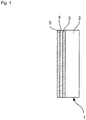
- Fig. 1 Fig. 10 is a diagram showing a cross section of a coating material 1 according to an embodiment of the present invention.
- the coating material 1 comprises a carrier layer 2 which, when the coating material 1 is applied to a workpiece W, points away from the latter.
- the carrier layer also takes over the task of a decorative material, and this may consist of various materials, have a pigmentation and / or be provided with a structure.
- the coating material 1 comprises an adhesive layer 5 which, when the coating material 1 is applied to a workpiece W, faces the workpiece W and provides an adhesive bond with the workpiece.
- a further layer 3 is provided, which in the present Embodiment is formed on a similar or same material as the adhesive layer. 5
- both the adhesion layer 5 and the further layer 3 comprise absorber elements, for example absorber particles, which are introduced into the adhesion layer 5 and the further layer 3.
- the absorber particles are characterized by the fact that they can absorb energy from an energy source and release it, for example, in the form of heat to their environment.
- the absorber particles are designed such that they are activated or heated by a laser beam, in order to thereby provide an activation of the adhesion layer 5 and the further layer 3. Since the adhesive layer primarily assumes the task of providing an adhesive bond to the workpiece, and the further layer is intended to compensate, for example, tolerances, it may be advantageous to provide a larger proportion of absorber particles in the adhesive layer 5 than in the further layer 3. It is however, it can be seen that the proportions of absorber particles can be varied according to the specific tasks.
- an activation support is present between the adhesion layer 5 and the further layer 3.
- Separating layer 4 is provided, which prevents an indirect activation of the further layer 3 takes place by an activation of the adhesive layer 5.
- the separating layer can also assume the task that no mixing of the adhesive layer and the further layer 3 takes place.
- FIG. 2 is a schematic plan view of an apparatus for mounting the coating material 1 to a workpiece W.
- the workpiece W is moved in a passing direction moves, and the coating material 1 is supplied from a memory 14.
- the memory 14 comprises a plurality of compartments in which various coating materials can be loaded.
- the illustrated apparatus 10 includes a pinch roller 12 by which a portion of the coating material 1 cut to the side length of the workpiece W can be attached to this workpiece W by pressing the coating material against the workpiece W with pressure. Furthermore, a plurality of Nachdrückrollen 13 are provided in the device 10, which ensure the adhesion after the joining of the coating material 1 on the workpiece W.
Description
Die vorliegende Erfindung betrifft ein Verfahren zum Beschichten eines Werkstücks, an bevorzugt einer Schmalseite eines Werkstücks. Die hier betroffenen Werkstücke sind insbesondere aus Holz, Holzwerkstoffen, wie Spanplatten, oder Verbundmaterial. Ferner können die angesprochenen Werkstücke aus Leichtbaumaterial sein.The present invention relates to a method for coating a workpiece, preferably a narrow side of a workpiece. The workpieces concerned here are in particular made of wood, wood-based materials, such as chipboard, or composite material. Furthermore, the addressed workpieces can be made of lightweight construction material.
Unter Beschichtungsmaterial wird in dieser Anmeldung ein Beschichtungsmaterial mit begrenzter Flexibilität verstanden, wie zum Beispiel eine bahnförmige oder streifenförmige Schmalseitenbeschichtung aus Kunststoff oder Echtholzfurnier.Coating material in this application is understood to mean a coating material with limited flexibility, such as, for example, a web-shaped or strip-shaped narrow-side coating of plastic or real wood veneer.
Als Stand der Technik ist die
Ferner ist die
Als weiterer Stand der Technik ist die
Ferner ist die
Generell ist es bekannt, ein Haftmittel zwischen einer Holzwerkstoffplatte und einem Beschichtungsmaterial zu verwenden. Dabei kommen dem Haftmittel unterschiedliche Aufgaben zu, insbesondere das Füllen offenporiger Abschnitte des Werkstücks, Bereitstellen einer Haftung zum Holzwerkstoff und ggf. losen Spänen, sowie Haftung zum Deckmaterial/Beschichtungsmaterial.In general, it is known to use an adhesive between a wood-based panel and a coating material. The adhesive comes different Tasks to, in particular the filling of open-pored sections of the workpiece, providing adhesion to the wood material and possibly loose chips, and adhesion to the cover material / coating material.
Wird eines der zuvor genannten Beschichtungsmaterialien auf ein Werkstück aufgebracht, so ist es üblich, dass in einem nachfolgenden Verfahrensschritt ggf. austretendes Haftmaterial mittels einer Ziehklinge entfernt wird, und/oder die Kanten mit einem Bearbeitungswerkzeug, insbesondere Profilfräser, nachbearbeitet werden. Bei dieser Nachbearbeitung wird überstehendes Beschichtungsmaterial entfernt und ggf. eine Form wie ein Radius in das Beschichtungsmaterial eingebracht.If one of the abovementioned coating materials is applied to a workpiece, then it is customary that, in a subsequent method step, any adhering adhesive material that may be removed is removed by means of a scraper blade, and / or the edges are finished with a processing tool, in particular profile milling cutter. In this post-processing, protruding coating material is removed and, if necessary, a form such as a radius is introduced into the coating material.
Hierbei hat sich gezeigt, dass zum einen Toleranzen an der zu beschichtenden Seite des Werkstücks ausgeglichen werden müssen, um den hohen Kundenanforderungen gerecht zu werden. Ferner wurde festgestellt, dass auch das Beschichtungsmaterial selbst Dickentoleranzen aufweisen kann, die im Stand der Technik ggf. ohne weitere Kombination in die Bearbeitungsergebnisse einfließen. In diesem Zusammenhang wird auf die deutsche Patentanmeldung mit dem amtlichen Aktenzeichen 10 2012 302 503.0 verwiesen, die auf ein Verfahren sowie eine Vorrichtung zur Kompensation von Dickentoleranzen des Beschichtungsmaterials gerichtet ist.It has been found that on the one hand tolerances on the side of the workpiece to be coated must be compensated in order to meet the high customer requirements. It has also been found that the coating material itself can also have thickness tolerances, which may be included in the processing results without further combination in the prior art. In this context, reference is made to the German patent application with the
Aufgabe der vorliegenden Erfindung ist es, ein Beschichtungsverfahren bereitzustellen, wobei das Beschichtungsmaterial selbst auf die durch das jeweilige Werkstück gestellten Anforderungen reagieren kann, um eine optisch ansprechende Beschichtung des Werkstücks zu erreichen.The object of the present invention is to provide a coating method, wherein the coating material itself can react to the requirements imposed by the respective workpiece in order to achieve a visually appealing coating of the workpiece.
Diese Aufgabe wird durch ein Verfahren gemäß Anspruch 1 erreicht. Weitere bevorzugte Ausführungsformen sind den abhängigen Ansprüchen zu entnehmen.This object is achieved by a method according to
Kerngedanke der vorliegenden Erfindung ist es dabei, das Beschichtungsmaterial mehrschichtig bereitzustellen, wobei neben einer Trägerschicht mehrere aktivierbare Schichten zur Verfügung gestellt werden, die jeweils durch einen Energieeintrag aktivierbar sind. Hierbei ist die Haftschicht, die beim Fügen des Beschichtungsmaterials am Werkstück mit diesem in Kontakt kommt, primär - jedoch nicht ausschließlich - zum Bereitstellen einer adhäsiven Bindung vorgesehen. Eine weitere aktivierbare Schicht, die sich zwischen der Trägerschicht und der aktivierbaren Haftschicht befindet, soll eine weitere Funktion übernehmen, um das Beschichtungsmaterial an die Anforderungen des jeweiligen Werkstücks anzupassen. Beispielsweise kann die weitere Schicht als eine Ausgleichs- oder Toleranzschicht fungieren, um beispielsweise Unebenheiten am Werkstück oder Unregelmäßigkeiten der Dicke des Beschichtungsmaterials auszugleichen.It is the core idea of the present invention to provide the coating material in a multi-layered manner, wherein, in addition to a carrier layer, a plurality of activatable layers are provided which can each be activated by an energy input. Here, the adhesive layer, which comes into contact with the workpiece during the joining of the coating material, is primarily, but not exclusively, provided for providing an adhesive bond. Another activatable layer, which is located between the carrier layer and the activatable adhesive layer, is to assume a further function in order to adapt the coating material to the requirements of the respective workpiece. For example, the further layer can act as a leveling or tolerance layer, for example to compensate for unevennesses on the workpiece or irregularities in the thickness of the coating material.
"Aktivierbar" im Sinne der vorliegenden Anmeldung bedeutet, dass das entsprechende Element, also beispielsweise die Haftschicht oder die weitere Schicht, mittels Energieeintrag von einem festen Zustand in einen weichen Zustand versetzt werden können, der der jeweiligen Schicht eine neue oder zusätzliche Funktion zuweist. Die Haftschicht entfaltet im aktivierten Zustand beispielsweise eine adhäsive Wirkung. Die weitere Schicht kann ebenfalls eine adhäsive Wirkung entfalten, und/oder ihr Volumen verändern. Die Änderung des Volumens kann nach der Aktivierung, insbesondere beim Erkalten der weiteren Schicht, dauerhaft bleiben."Activatable" in the sense of the present application means that the corresponding element, ie for example the adhesive layer or the further layer, can be shifted from a solid state to a soft state by energy input, which assigns a new or additional function to the respective layer. The adhesive layer unfolds in the activated state, for example, an adhesive effect. The further layer can also develop an adhesive effect, and / or change its volume. The change in volume can remain permanent after activation, in particular when the further layer cools.
"Aktivierungsträge" im Sinne der vorliegenden Anmeldung bedeutet, dass das entsprechende Element weniger bis gar nicht auf eine eingebrachte Energie reagiert."Activation" in the context of the present application means that the corresponding element reacts less or not at all to an introduced energy.
Bei den in dieser Anmeldung genannten Breit- oder Schmalseiten handelt es sich z.B. um die Arbeitsseite oder Stirnseite eines Werkstücks, rein beispielhaft einer Küchenarbeitsplatte.The broadsides or narrow sides mentioned in this application are e.g. around the working side or end face of a workpiece, purely by way of example a kitchen worktop.
Das erfindungsgemäß verwendete Beschichtungsmaterial hat den Vorteil, dass dieses eine Reihe von Funktionen erfüllt. Zum einen können durch die Haftschicht Poren des Werkstücks gefüllt werden, und eine Haftung zum Werkstoff des Werkstücks (beispielsweise Holzwerkstoff und lose Späne) sowie zum Trägermaterial wird sichergestellt. Ferner wird das Werkstück, das beispielsweise aus einem Holzwerkstoff besteht, durch die Beschichtung vergütet, und die physikalischen Eigenschaften werden verbessert. Bei der Nachbearbeitung in einer Beschichtungsmaschine werden die Nachbearbeitungswerkzeuge und die Möbelplatte "verschmiert". Ferner kann sowohl die Form als auch die Lage des Beschichtungsmaterials stabil gehalten werden.The coating material used according to the invention has the advantage that it fulfills a number of functions. On the one hand can be filled by the adhesive layer pores of the workpiece, and adhesion to the material of the workpiece (for example, wood material and loose chips) and to the carrier material is ensured. Further, the workpiece, which is made of a wood material, for example, is tempered by the coating, and the physical properties are improved. During post-processing in a coating machine, the post-processing tools and the furniture panel are "smeared". Furthermore, both the shape and the position of the coating material can be kept stable.
Darüber hinaus können die Schichten des erfindungsgemäßen Beschichtungsmaterials auf weitere Anforderungen an das zu beschichtende Werkstück abgestimmt werden. Handelt es sich beispielsweise um ein Möbelstück, so kann dieses auf seinen Einsatz im Wohnbereich, in der Küche oder einem Feuchtraum ausgelegt werden.In addition, the layers of the coating material according to the invention can be adapted to further requirements for the workpiece to be coated. For example, if it is a piece of furniture, it may be designed for use in the home, kitchen or wet room.
Das neuartige Beschichtungsmaterial kann - rein beispielhaft - auf ein Möbelelement oder Ähnliches aufgebracht werden. Die Vergütung des Möbelelements kann mit dem erfindungsgemäßen Beschichtungsmaterial aufgewertet und die physikalischen Eigenschaften verbessert werden (Feuchtigkeit, Wärme). Im Übrigen kann das Design des Haftmittels abgestimmt mit den konkreten Ansprüchen weiterentwickelt werden.The novel coating material can - purely by way of example - be applied to a furniture element or the like. The coating of the furniture element can be upgraded with the coating material according to the invention and the physical properties improved (moisture, heat). Incidentally, the design of the Adhesive to be further developed with the specific requirements.
Gemäß einer bevorzugten Ausführungsform ist eine Trennschicht zwischen der Haftschicht und der weiteren Schicht vorgesehen ist, welche Trennschicht aktivierungsträge ist. Auf diese Weise stellt die Trennschicht sicher, dass die Haftschicht und die weitere Schicht bei Aktivierung von zumindest einer dieser Schichten nicht durchmischt werden. Demnach können die Haftschicht und die weitere Schicht stets ihre jeweilige Funktion erfüllen.According to a preferred embodiment, a separating layer is provided between the adhesive layer and the further layer, which separating layer is activation-promoting. In this way, the release layer ensures that the adhesive layer and the further layer are not mixed upon activation of at least one of these layers. Accordingly, the adhesive layer and the further layer can always fulfill their respective function.
Gemäß einer weiteren Ausführungsform sind die Haftschicht und die weitere Schicht durch die gleiche Energiequelle aktivierbar. Demnach kann die gleiche Energiequelle genutzt werden. Alternativ hierzu können die Haftschicht und die weitere Schicht durch unterschiedliche Energiequellen aktivierbar sein. Gemäß dieser Alternative kann auf die jeweiligen Anforderungen bzw. die jeweilige Zusammensetzung der Haftschicht und der weiteren Schicht gezielt Einfluss genommen werden.According to a further embodiment, the adhesive layer and the further layer can be activated by the same energy source. Accordingly, the same energy source can be used. Alternatively, the adhesive layer and the further layer can be activated by different energy sources. According to this alternative, specific influence can be exerted on the respective requirements or the respective composition of the adhesive layer and the further layer.
Bei der zumindest einen genannten Energiequellen kann es sich um eine Energiequelle handeln, die ausgewählt ist aus der Gruppe aufweisend Laser, LED, Heißluftquelle, Infrarotquelle, Ultraschallquelle, Magnetfeldquelle, Mikrowellenquelle, Plasmaquelle, und Begasungsquelle, insbesondere Heißluft- oder Heißgasquelle (ggf. mit Überdruck).The at least one mentioned energy source may be an energy source which is selected from the group comprising laser, LED, hot air source, infrared source, ultrasound source, magnetic field source, microwave source, plasma source, and fumigation source, in particular hot air or hot gas source (optionally with overpressure ).
Der Laser erlaubt einen genau dosierbaren Energieeintrag in die Haftschicht und/oder weitere Schicht, und ermöglicht eine besonders schnelle Fokussierung der Energie auf einem zu aktivierenden Bereich. Ferner lässt sich mittels des Lasers die Energie besonders schnell bereitstellen, was eine besonders gute Prozessdynamik ermöglicht.The laser allows a precisely metered energy input into the adhesive layer and / or further layer, and allows a particularly fast focusing of the energy on an area to be activated. Furthermore, the energy can be made available very quickly by means of the laser, which enables particularly good process dynamics.
Die Begasungsquelle, insbesondere Heißluft- oder Heißgasquelle, ist eine relativ kostengünstige Variante, die keine besonderen Anschaffungen beim Kunden erfordert.The fumigation source, in particular hot air or hot gas source, is a relatively inexpensive variant that requires no special purchases from the customer.
Bevorzugt ist ein Absorber, beispielsweise Farbpigmente, in der Haftschicht und bevorzugt in der weiteren Schicht vorgesehen ist, der insbesondere durch einen Laser aktivierbar ist. Der prozentuale Anteil des Absorbers in der Haftschicht bzw. der weiteren Schicht kann gemäß den jeweiligen Anforderungen eingestellt werden. Beispielsweise können die Haftschicht und die weitere Schicht einen gleichen prozentualen Anteil des Absorbers aufweisen, oder die Anteile des Absorbers der Haftschicht bzw. der weiteren Schicht können sich voneinander unterscheiden.An absorber, for example color pigments, is preferably provided in the adhesion layer and preferably in the further layer, which can be activated in particular by a laser. The percentage of the absorber in the adhesive layer or the further layer can be adjusted according to the respective requirements. For example, the adhesive layer and the further layer can have the same percentage of the absorber, or the proportions of the absorber of the adhesive layer or of the further layer can differ from one another.
Die Trägerschicht kann ausgewählt sein aus der Gruppe, umfassend Papier, Pappe, Melamin, CPL (Continuous Pressing Laminate), Furnier, Kunststoff, insbesondere thermoplastischen Kunststoff, Metall, und Kombinationen hiervon. Das erfindungsgemäße Beschichtungsmaterial ist demnach variabel einsetzbar.The backing layer may be selected from the group comprising paper, paperboard, melamine, CPL (Continuous Pressing Laminate), veneer, plastic, especially thermoplastic, metal, and combinations thereof. Accordingly, the coating material according to the invention can be used variably.
Eine weitere Ausführungsform des Verfahrens zeichnet sich dadurch aus, dass eine Absorberschicht an der Haftschicht angebracht, insbesondere aufgewalzt, ist, bevorzugt an der von der Trägerschicht weg weisenden Seite der Haftschicht. Diese Absorberschicht kann mittels einer der bereits genannten Energiequellen, insbesondere jedoch mit einem Laser, erwärmt werden. Die Wärme der Absorberschicht wird dann an die Haftschicht und an die weitere Schicht weitergegeben, um diese zu aktivieren.A further embodiment of the method is characterized in that an absorber layer is applied, in particular rolled, to the adhesion layer, preferably on the side of the adhesion layer facing away from the carrier layer. This absorber layer can be heated by means of one of the already mentioned energy sources, but in particular with a laser. The heat of the absorber layer is then passed on to the adhesive layer and to the further layer to activate it.
- Fig. 1Fig. 1
- ist eine Querschnittsansicht eines Beschichtungsmaterials gemäß einer Ausführungsform der vorliegenden Erfindung.FIG. 10 is a cross-sectional view of a coating material according to an embodiment of the present invention. FIG.
- Fig. 2Fig. 2
- ist eine Draufsicht auf eine Vorrichtung zur Anbringung eines Beschichtungsmaterials an einem WerkstückFIG. 10 is a plan view of a device for attaching a coating material to a workpiece. FIG
Nachfolgend wird anhand der beigefügten Figuren eine bevorzugte Ausführungsform der vorliegenden Erfindung beschrieben. Weitere in diesem Zusammenhang genannten Variationen und Modifikationen können jeweils miteinander kombiniert werden, um neue Ausführungsformen der vorliegenden Erfindung auszubilden.Hereinafter, a preferred embodiment of the present invention will be described with reference to the accompanying drawings. Other variations and modifications mentioned herein may be combined with each other to form new embodiments of the present invention.
Ferner umfasst das Beschichtungsmaterial 1 eine Haftschicht 5, die bei Aufbringung des Beschichtungsmaterials 1 auf ein Werkstück W zu diesem weist und eine adhäsive Bindung mit dem Werkstück bereitstellt.Furthermore, the
Zwischen der Haftschicht 5 und der Trägerschicht 2 ist eine weitere Schicht 3 vorgesehen, die in der vorliegenden Ausführungsform auf einem ähnlichen bzw. gleichen Material ausgebildet ist wie die Haftschicht 5.Between the
Gemäß der vorliegenden Ausführungsform umfassen demnach sowohl die Haftschicht 5 als auch die weitere Schicht 3 Absorberelemente, beispielsweise Absorberpartikel, die in die Haftschicht 5 und die weitere Schicht 3 eingebracht sind. Die Absorberpartikel zeichnen sich dadurch aus, dass diese durch eine Energiequelle Energie aufnehmen können, und diese beispielsweise in Form von Wärme an ihre Umgebung abgeben.According to the present embodiment, therefore, both the
Im Rahmen der vorliegenden Ausführungsform sind die Absorberpartikel so ausgebildet, dass sie durch einen Laserstrahl aktiviert bzw. erwärmt werden, um hierdurch eine Aktivierung der Haftschicht 5 sowie der weiteren Schicht 3 bereitzustellen. Da die Haftschicht primär die Aufgabe übernimmt, eine adhäsive Bindung zum Werkstück bereitzustellen, und die weitere Schicht dazu vorgesehen ist, beispielsweise Toleranzen auszugleichen, kann vorteilhaft sein, in der Haftschicht 5 einen größeren Anteil an Absorberpartikeln vorzusehen als in der weiteren Schicht 3. Es ist jedoch ersichtlich, dass die Anteile an Absorberpartikeln entsprechend den konkreten Aufgaben variiert werden können.In the context of the present embodiment, the absorber particles are designed such that they are activated or heated by a laser beam, in order to thereby provide an activation of the
Gemäß der vorliegenden Ausführungsform ist zwischen der Haftschicht 5 und der weiteren Schicht 3 eine aktivierungsträge. Trennschicht 4 vorgesehen, die verhindert, dass eine mittelbare Aktivierung der weiteren Schicht 3 durch eine Aktivierung der Haftschicht 5 stattfindet. Alternativ oder zusätzlich hierzu kann die Trennschicht auch die Aufgabe übernehmen, dass keine Vermischung der Haftschicht und der weiteren Schicht 3 stattfindet.According to the present embodiment, an activation support is present between the
Die gezeigte Vorrichtung 10 umfasst eine Andruckrolle 12, mit der ein auf die Seitenlänge des Werkstücks W zugeschnittener Abschnitt des Beschichtungsmaterials 1 an diesem Werkstück W angebracht werden kann, indem das Beschichtungsmaterial mit Druck gegen das Werkstück W gepresst wird. Ferner sind mehrere Nachdrückrollen 13 in der Vorrichtung 10 vorgesehen, die nach dem Fügen des Beschichtungsmaterials 1 am Werkstück W das Anhaften sicherstellen.The illustrated
Claims (7)
- Method for coating a workpiece, in particular on its narrow side, with a coating material (1), wherein the coating material (1) is multi-layered and has a carrier layer (2), an activatable adhesive layer (5) and a further activatable layer between the carrier layer (2) and the activatable adhesive layer (5), having the steps of:delivering the coating material (1),activating at least the adhesive layer (5) by means of a first energy source,activating the further activatable layer (3) by means of a second energy source,wherein the first and second energy sources are different,moving the coating material (1) and a workpiece (W) relative to each other, and in the process pressing the coating material (1) against the workpiece (W).
- Method according to claim 1, characterised in that a separating layer (4) is provided between the adhesive layer (5) and the further activatable layer (3), which separating layer (4) does not react to activation.
- Method according to any of the preceding claims, characterised in that the at least one energy source is selected from the group consisting of laser, LED, hot air source, infrared source, ultrasound source, magnetic field source, microwave source, plasma source and gas supply source, in particular hot air or hot gas source, the latter if occasion arises with overpressure.
- Method according to any of the preceding claims, characterised in that an absorber, in particular colour pigments, is provided in the adhesive layer (5) and preferably in the further activatable layer (3), which is in particular activatable by a laser.
- Method according to any of the preceding claims, characterised in that the carrier layer (2) is selected from the group comprising paper, cardboard, melamine, CPL, veneer, solid wood, plastic, in particular thermoplastic material, metal and combinations thereof.
- Method according to any of claims 1-4, characterised in that at least the carrier layer (2) is a co-extruded layer, preferably all layers of the coating material (1).
- Method according to any of the preceding claims, characterised in that an absorber layer is applied to the adhesive layer (5), in particular rolled on, preferably on the side of the adhesive layer (5) facing away from the carrier layer (2).
Applications Claiming Priority (2)
| Application Number | Priority Date | Filing Date | Title |
|---|---|---|---|
| DE102012223987.1A DE102012223987A1 (en) | 2012-12-20 | 2012-12-20 | Intelligent laser edge |
| PCT/EP2013/076876 WO2014095844A1 (en) | 2012-12-20 | 2013-12-17 | Edge strip |
Publications (2)
| Publication Number | Publication Date |
|---|---|
| EP2934877A1 EP2934877A1 (en) | 2015-10-28 |
| EP2934877B1 true EP2934877B1 (en) | 2017-10-25 |
Family
ID=49841663
Family Applications (1)
| Application Number | Title | Priority Date | Filing Date |
|---|---|---|---|
| EP13811187.7A Not-in-force EP2934877B1 (en) | 2012-12-20 | 2013-12-17 | Edge-band |
Country Status (3)
| Country | Link |
|---|---|
| EP (1) | EP2934877B1 (en) |
| DE (1) | DE102012223987A1 (en) |
| WO (1) | WO2014095844A1 (en) |
Families Citing this family (3)
| Publication number | Priority date | Publication date | Assignee | Title |
|---|---|---|---|---|
| DE102014214035A1 (en) | 2014-07-18 | 2016-01-21 | Homag Holzbearbeitungssysteme Gmbh | Method, apparatus and synthesis element for joining an edge material to a workpiece |
| DE102016118644A1 (en) | 2016-09-30 | 2018-04-05 | Döllken-Kunststoffverarbeitung Gmbh | lipping |
| FI129331B (en) | 2017-03-07 | 2021-12-15 | Lemtapes Oy | Method and apparatus for adhesive activation |
Family Cites Families (16)
| Publication number | Priority date | Publication date | Assignee | Title |
|---|---|---|---|---|
| US3916046A (en) * | 1971-09-13 | 1975-10-28 | Minnesota Mining & Mfg | Decorative adhesive laminate, for heat-pressure application to substrates |
| DE4208991A1 (en) * | 1992-03-20 | 1993-09-23 | Alkor Gmbh | PLASTIC EDGEBAND, METHOD FOR THE PRODUCTION AND USE THEREOF |
| JPH07224253A (en) * | 1994-02-09 | 1995-08-22 | Sliontec:Kk | Hot-melt adhesive sheet |
| DE69637984D1 (en) | 1995-12-28 | 2009-09-17 | Panasonic Corp | Optical waveguide, optical wavelength conversion device and method of making the same |
| IL116655A0 (en) | 1996-01-02 | 1996-05-14 | Taal Manufacturers Of Plywood | Coated board of wood |
| US6183862B1 (en) * | 1998-09-23 | 2001-02-06 | Avery Dennison Corporation | Multilayer PSA construction exhibiting reduced tackifier migration |
| DE19907939C1 (en) * | 1999-02-24 | 2000-05-31 | Homag Maschinenbau Ag | Continuous application of a decorative strip onto the porous narrow edge of wood-based workpieces by applying a filling and bonding compound to the edge, then the strip |
| US6333073B1 (en) * | 1999-02-25 | 2001-12-25 | Premark Rwp Holdings, Inc. | Adhesive tape and products made therefrom |
| DE19940329A1 (en) | 1999-08-25 | 2001-03-01 | Doellken & Co Gmbh W | Process for fastening cover strips on the narrow sides of furniture panels |
| DE19955575B4 (en) | 1999-11-18 | 2010-04-08 | Brandt Kantentechnik Gmbh | Method and device for adhering a cover material to workpiece surfaces of continuously moving or stationarily arranged plate- or strip-shaped workpieces |
| DE10235019A1 (en) * | 2002-07-31 | 2004-02-12 | Homag Holzbearbeitungssysteme Ag | Process for coating plate-shaped workpieces with a decorative film |
| DE102006007869A1 (en) * | 2006-02-17 | 2007-08-30 | Jowat Ag | Process for laminating plastic films on wood-based substrates, in particular for producing high-gloss surfaces |
| DE102010008821A1 (en) * | 2010-02-22 | 2011-08-25 | Homag Holzbearbeitungssysteme AG, 72296 | Process for coating components |
| DE102011015898B4 (en) | 2011-04-01 | 2016-10-06 | Christof Schulte-Göbel | Narrow area coating device and method for applying an adhesive-free heat-activatable edge coating by means of hot air or hot gas |
| DE102011085996A1 (en) * | 2011-11-09 | 2013-05-16 | Henkel Ag & Co. Kgaa | Multi-edge bonding |
| DE102012202503A1 (en) | 2012-02-17 | 2013-08-22 | Homag Holzbearbeitungssysteme Gmbh | Method for processing edge of e.g. wooden plate with edge tape, used in furniture and component industry, involves adjusting profile cutter based on detection result of thickness allowance of edge tape in Y-direction |
-
2012
- 2012-12-20 DE DE102012223987.1A patent/DE102012223987A1/en not_active Withdrawn
-
2013
- 2013-12-17 WO PCT/EP2013/076876 patent/WO2014095844A1/en active Application Filing
- 2013-12-17 EP EP13811187.7A patent/EP2934877B1/en not_active Not-in-force
Non-Patent Citations (1)
| Title |
|---|
| None * |
Also Published As
| Publication number | Publication date |
|---|---|
| DE102012223987A1 (en) | 2014-06-26 |
| WO2014095844A1 (en) | 2014-06-26 |
| EP2934877A1 (en) | 2015-10-28 |
Similar Documents
| Publication | Publication Date | Title |
|---|---|---|
| EP1852242B1 (en) | Cover moulding | |
| DE10124913C1 (en) | Process for the production of a three-dimensionally bendable surface element | |
| WO2003074814A1 (en) | Panels provided with a friction-based fixing | |
| DE202007011911U1 (en) | Edging strip for furniture | |
| DE102010014776A1 (en) | Edge strip made of thermoplastic material, in particular for furniture panels | |
| EP2934877B1 (en) | Edge-band | |
| EP3322596A1 (en) | Method for producing a laminate consisting of a backing sheet and decorative paper | |
| DE202015104158U1 (en) | lipping | |
| EP1984191B1 (en) | Process for production of a profile strip | |
| EP2688722B1 (en) | Method for edging wood-based material boards | |
| DE202008004011U1 (en) | Multilayer flexible material plate | |
| EP1386720B1 (en) | Method for coating plate-like workpieces with a decorative foil | |
| EP3356058B1 (en) | Method for coating a, preferably planar, workpiece | |
| EP2616250A1 (en) | Interior fitting component for cladding and process for producing an interior fitting component | |
| DE102015121551A1 (en) | Edging strip for furniture | |
| EP2774744B1 (en) | Edge strip | |
| EP3651955B1 (en) | Edge band and process to mount the band | |
| DE102017003640A1 (en) | Covering element for a covering and method for producing such a covering element | |
| EP2726281B1 (en) | Sandwich panel, in particular for a piece of furniture, and production method | |
| DE202009011402U1 (en) | lightweight panel | |
| DE202010004845U1 (en) | Panel material for interior work | |
| DE102006055951A1 (en) | Method and device for coating a wood-based panel with a foil | |
| DE102014106419B4 (en) | Method and device for the surface bonding of two substrates | |
| DE202010004931U1 (en) | Edge strip made of thermoplastic material, in particular for furniture panels | |
| EP2907958B1 (en) | Method for manufacturing of door wings |
Legal Events
| Date | Code | Title | Description |
|---|---|---|---|
| PUAI | Public reference made under article 153(3) epc to a published international application that has entered the european phase |
Free format text: ORIGINAL CODE: 0009012 |
|
| 17P | Request for examination filed |
Effective date: 20150716 |
|
| AK | Designated contracting states |
Kind code of ref document: A1 Designated state(s): AL AT BE BG CH CY CZ DE DK EE ES FI FR GB GR HR HU IE IS IT LI LT LU LV MC MK MT NL NO PL PT RO RS SE SI SK SM TR |
|
| AX | Request for extension of the european patent |
Extension state: BA ME |
|
| DAX | Request for extension of the european patent (deleted) | ||
| 17Q | First examination report despatched |
Effective date: 20160422 |
|
| RAP1 | Party data changed (applicant data changed or rights of an application transferred) |
Owner name: HOMAG GMBH |
|
| GRAP | Despatch of communication of intention to grant a patent |
Free format text: ORIGINAL CODE: EPIDOSNIGR1 |
|
| INTG | Intention to grant announced |
Effective date: 20170406 |
|
| GRAS | Grant fee paid |
Free format text: ORIGINAL CODE: EPIDOSNIGR3 |
|
| GRAJ | Information related to disapproval of communication of intention to grant by the applicant or resumption of examination proceedings by the epo deleted |
Free format text: ORIGINAL CODE: EPIDOSDIGR1 |
|
| GRAL | Information related to payment of fee for publishing/printing deleted |
Free format text: ORIGINAL CODE: EPIDOSDIGR3 |
|
| INTC | Intention to grant announced (deleted) | ||
| GRAR | Information related to intention to grant a patent recorded |
Free format text: ORIGINAL CODE: EPIDOSNIGR71 |
|
| GRAA | (expected) grant |
Free format text: ORIGINAL CODE: 0009210 |
|
| AK | Designated contracting states |
Kind code of ref document: B1 Designated state(s): AL AT BE BG CH CY CZ DE DK EE ES FI FR GB GR HR HU IE IS IT LI LT LU LV MC MK MT NL NO PL PT RO RS SE SI SK SM TR |
|
| INTG | Intention to grant announced |
Effective date: 20170915 |
|
| REG | Reference to a national code |
Ref country code: GB Ref legal event code: FG4D Free format text: NOT ENGLISH |
|
| REG | Reference to a national code |
Ref country code: CH Ref legal event code: EP |
|
| REG | Reference to a national code |
Ref country code: AT Ref legal event code: REF Ref document number: 939530 Country of ref document: AT Kind code of ref document: T Effective date: 20171115 |
|
| REG | Reference to a national code |
Ref country code: IE Ref legal event code: FG4D Free format text: LANGUAGE OF EP DOCUMENT: GERMAN |
|
| REG | Reference to a national code |
Ref country code: DE Ref legal event code: R096 Ref document number: 502013008676 Country of ref document: DE |
|
| REG | Reference to a national code |
Ref country code: NL Ref legal event code: MP Effective date: 20171025 |
|
| REG | Reference to a national code |
Ref country code: LT Ref legal event code: MG4D |
|
| PG25 | Lapsed in a contracting state [announced via postgrant information from national office to epo] |
Ref country code: NL Free format text: LAPSE BECAUSE OF FAILURE TO SUBMIT A TRANSLATION OF THE DESCRIPTION OR TO PAY THE FEE WITHIN THE PRESCRIBED TIME-LIMIT Effective date: 20171025 |
|
| PG25 | Lapsed in a contracting state [announced via postgrant information from national office to epo] |
Ref country code: LT Free format text: LAPSE BECAUSE OF FAILURE TO SUBMIT A TRANSLATION OF THE DESCRIPTION OR TO PAY THE FEE WITHIN THE PRESCRIBED TIME-LIMIT Effective date: 20171025 Ref country code: FI Free format text: LAPSE BECAUSE OF FAILURE TO SUBMIT A TRANSLATION OF THE DESCRIPTION OR TO PAY THE FEE WITHIN THE PRESCRIBED TIME-LIMIT Effective date: 20171025 Ref country code: ES Free format text: LAPSE BECAUSE OF FAILURE TO SUBMIT A TRANSLATION OF THE DESCRIPTION OR TO PAY THE FEE WITHIN THE PRESCRIBED TIME-LIMIT Effective date: 20171025 Ref country code: SE Free format text: LAPSE BECAUSE OF FAILURE TO SUBMIT A TRANSLATION OF THE DESCRIPTION OR TO PAY THE FEE WITHIN THE PRESCRIBED TIME-LIMIT Effective date: 20171025 Ref country code: NO Free format text: LAPSE BECAUSE OF FAILURE TO SUBMIT A TRANSLATION OF THE DESCRIPTION OR TO PAY THE FEE WITHIN THE PRESCRIBED TIME-LIMIT Effective date: 20180125 |
|
| PG25 | Lapsed in a contracting state [announced via postgrant information from national office to epo] |
Ref country code: BG Free format text: LAPSE BECAUSE OF FAILURE TO SUBMIT A TRANSLATION OF THE DESCRIPTION OR TO PAY THE FEE WITHIN THE PRESCRIBED TIME-LIMIT Effective date: 20180125 Ref country code: IS Free format text: LAPSE BECAUSE OF FAILURE TO SUBMIT A TRANSLATION OF THE DESCRIPTION OR TO PAY THE FEE WITHIN THE PRESCRIBED TIME-LIMIT Effective date: 20180225 Ref country code: GR Free format text: LAPSE BECAUSE OF FAILURE TO SUBMIT A TRANSLATION OF THE DESCRIPTION OR TO PAY THE FEE WITHIN THE PRESCRIBED TIME-LIMIT Effective date: 20180126 Ref country code: LV Free format text: LAPSE BECAUSE OF FAILURE TO SUBMIT A TRANSLATION OF THE DESCRIPTION OR TO PAY THE FEE WITHIN THE PRESCRIBED TIME-LIMIT Effective date: 20171025 Ref country code: HR Free format text: LAPSE BECAUSE OF FAILURE TO SUBMIT A TRANSLATION OF THE DESCRIPTION OR TO PAY THE FEE WITHIN THE PRESCRIBED TIME-LIMIT Effective date: 20171025 Ref country code: RS Free format text: LAPSE BECAUSE OF FAILURE TO SUBMIT A TRANSLATION OF THE DESCRIPTION OR TO PAY THE FEE WITHIN THE PRESCRIBED TIME-LIMIT Effective date: 20171025 |
|
| REG | Reference to a national code |
Ref country code: DE Ref legal event code: R097 Ref document number: 502013008676 Country of ref document: DE |
|
| PG25 | Lapsed in a contracting state [announced via postgrant information from national office to epo] |
Ref country code: CY Free format text: LAPSE BECAUSE OF FAILURE TO SUBMIT A TRANSLATION OF THE DESCRIPTION OR TO PAY THE FEE WITHIN THE PRESCRIBED TIME-LIMIT Effective date: 20171025 Ref country code: EE Free format text: LAPSE BECAUSE OF FAILURE TO SUBMIT A TRANSLATION OF THE DESCRIPTION OR TO PAY THE FEE WITHIN THE PRESCRIBED TIME-LIMIT Effective date: 20171025 Ref country code: DK Free format text: LAPSE BECAUSE OF FAILURE TO SUBMIT A TRANSLATION OF THE DESCRIPTION OR TO PAY THE FEE WITHIN THE PRESCRIBED TIME-LIMIT Effective date: 20171025 Ref country code: SK Free format text: LAPSE BECAUSE OF FAILURE TO SUBMIT A TRANSLATION OF THE DESCRIPTION OR TO PAY THE FEE WITHIN THE PRESCRIBED TIME-LIMIT Effective date: 20171025 Ref country code: CZ Free format text: LAPSE BECAUSE OF FAILURE TO SUBMIT A TRANSLATION OF THE DESCRIPTION OR TO PAY THE FEE WITHIN THE PRESCRIBED TIME-LIMIT Effective date: 20171025 |
|
| REG | Reference to a national code |
Ref country code: CH Ref legal event code: PL |
|
| PG25 | Lapsed in a contracting state [announced via postgrant information from national office to epo] |
Ref country code: PL Free format text: LAPSE BECAUSE OF FAILURE TO SUBMIT A TRANSLATION OF THE DESCRIPTION OR TO PAY THE FEE WITHIN THE PRESCRIBED TIME-LIMIT Effective date: 20171025 Ref country code: SM Free format text: LAPSE BECAUSE OF FAILURE TO SUBMIT A TRANSLATION OF THE DESCRIPTION OR TO PAY THE FEE WITHIN THE PRESCRIBED TIME-LIMIT Effective date: 20171025 Ref country code: RO Free format text: LAPSE BECAUSE OF FAILURE TO SUBMIT A TRANSLATION OF THE DESCRIPTION OR TO PAY THE FEE WITHIN THE PRESCRIBED TIME-LIMIT Effective date: 20171025 |
|
| PLBE | No opposition filed within time limit |
Free format text: ORIGINAL CODE: 0009261 |
|
| STAA | Information on the status of an ep patent application or granted ep patent |
Free format text: STATUS: NO OPPOSITION FILED WITHIN TIME LIMIT |
|
| REG | Reference to a national code |
Ref country code: IE Ref legal event code: MM4A |
|
| GBPC | Gb: european patent ceased through non-payment of renewal fee |
Effective date: 20180125 |
|
| PG25 | Lapsed in a contracting state [announced via postgrant information from national office to epo] |
Ref country code: MT Free format text: LAPSE BECAUSE OF FAILURE TO SUBMIT A TRANSLATION OF THE DESCRIPTION OR TO PAY THE FEE WITHIN THE PRESCRIBED TIME-LIMIT Effective date: 20171025 Ref country code: LU Free format text: LAPSE BECAUSE OF NON-PAYMENT OF DUE FEES Effective date: 20171217 |
|
| REG | Reference to a national code |
Ref country code: FR Ref legal event code: ST Effective date: 20180831 |
|
| 26N | No opposition filed |
Effective date: 20180726 |
|
| REG | Reference to a national code |
Ref country code: BE Ref legal event code: MM Effective date: 20171231 |
|
| PG25 | Lapsed in a contracting state [announced via postgrant information from national office to epo] |
Ref country code: IE Free format text: LAPSE BECAUSE OF NON-PAYMENT OF DUE FEES Effective date: 20171217 Ref country code: FR Free format text: LAPSE BECAUSE OF NON-PAYMENT OF DUE FEES Effective date: 20180102 |
|
| PG25 | Lapsed in a contracting state [announced via postgrant information from national office to epo] |
Ref country code: GB Free format text: LAPSE BECAUSE OF NON-PAYMENT OF DUE FEES Effective date: 20180125 Ref country code: SI Free format text: LAPSE BECAUSE OF FAILURE TO SUBMIT A TRANSLATION OF THE DESCRIPTION OR TO PAY THE FEE WITHIN THE PRESCRIBED TIME-LIMIT Effective date: 20171025 Ref country code: CH Free format text: LAPSE BECAUSE OF NON-PAYMENT OF DUE FEES Effective date: 20171231 Ref country code: LI Free format text: LAPSE BECAUSE OF NON-PAYMENT OF DUE FEES Effective date: 20171231 Ref country code: BE Free format text: LAPSE BECAUSE OF NON-PAYMENT OF DUE FEES Effective date: 20171231 |
|
| PG25 | Lapsed in a contracting state [announced via postgrant information from national office to epo] |
Ref country code: HU Free format text: LAPSE BECAUSE OF FAILURE TO SUBMIT A TRANSLATION OF THE DESCRIPTION OR TO PAY THE FEE WITHIN THE PRESCRIBED TIME-LIMIT; INVALID AB INITIO Effective date: 20131217 Ref country code: MC Free format text: LAPSE BECAUSE OF FAILURE TO SUBMIT A TRANSLATION OF THE DESCRIPTION OR TO PAY THE FEE WITHIN THE PRESCRIBED TIME-LIMIT Effective date: 20171025 |
|
| PG25 | Lapsed in a contracting state [announced via postgrant information from national office to epo] |
Ref country code: MK Free format text: LAPSE BECAUSE OF FAILURE TO SUBMIT A TRANSLATION OF THE DESCRIPTION OR TO PAY THE FEE WITHIN THE PRESCRIBED TIME-LIMIT Effective date: 20171025 |
|
| PGFP | Annual fee paid to national office [announced via postgrant information from national office to epo] |
Ref country code: DE Payment date: 20191210 Year of fee payment: 7 |
|
| PGFP | Annual fee paid to national office [announced via postgrant information from national office to epo] |
Ref country code: IT Payment date: 20191212 Year of fee payment: 7 |
|
| PG25 | Lapsed in a contracting state [announced via postgrant information from national office to epo] |
Ref country code: TR Free format text: LAPSE BECAUSE OF FAILURE TO SUBMIT A TRANSLATION OF THE DESCRIPTION OR TO PAY THE FEE WITHIN THE PRESCRIBED TIME-LIMIT Effective date: 20171025 |
|
| PGFP | Annual fee paid to national office [announced via postgrant information from national office to epo] |
Ref country code: AT Payment date: 20191121 Year of fee payment: 7 |
|
| PG25 | Lapsed in a contracting state [announced via postgrant information from national office to epo] |
Ref country code: PT Free format text: LAPSE BECAUSE OF FAILURE TO SUBMIT A TRANSLATION OF THE DESCRIPTION OR TO PAY THE FEE WITHIN THE PRESCRIBED TIME-LIMIT Effective date: 20171025 |
|
| PG25 | Lapsed in a contracting state [announced via postgrant information from national office to epo] |
Ref country code: AL Free format text: LAPSE BECAUSE OF FAILURE TO SUBMIT A TRANSLATION OF THE DESCRIPTION OR TO PAY THE FEE WITHIN THE PRESCRIBED TIME-LIMIT Effective date: 20171025 |
|
| REG | Reference to a national code |
Ref country code: DE Ref legal event code: R119 Ref document number: 502013008676 Country of ref document: DE |
|
| REG | Reference to a national code |
Ref country code: AT Ref legal event code: MM01 Ref document number: 939530 Country of ref document: AT Kind code of ref document: T Effective date: 20201217 |
|
| PG25 | Lapsed in a contracting state [announced via postgrant information from national office to epo] |
Ref country code: IT Free format text: LAPSE BECAUSE OF NON-PAYMENT OF DUE FEES Effective date: 20201217 Ref country code: AT Free format text: LAPSE BECAUSE OF NON-PAYMENT OF DUE FEES Effective date: 20201217 |
|
| PG25 | Lapsed in a contracting state [announced via postgrant information from national office to epo] |
Ref country code: DE Free format text: LAPSE BECAUSE OF NON-PAYMENT OF DUE FEES Effective date: 20210701 |