EP2675868B1 - Verbindungen für elektronische vorrichtungen - Google Patents
Verbindungen für elektronische vorrichtungen Download PDFInfo
- Publication number
- EP2675868B1 EP2675868B1 EP12701829.9A EP12701829A EP2675868B1 EP 2675868 B1 EP2675868 B1 EP 2675868B1 EP 12701829 A EP12701829 A EP 12701829A EP 2675868 B1 EP2675868 B1 EP 2675868B1
- Authority
- EP
- European Patent Office
- Prior art keywords
- atoms
- aromatic
- substituted
- radicals
- groups
- Prior art date
- Legal status (The legal status is an assumption and is not a legal conclusion. Google has not performed a legal analysis and makes no representation as to the accuracy of the status listed.)
- Not-in-force
Links
- 150000001875 compounds Chemical class 0.000 title claims description 124
- 125000003118 aryl group Chemical group 0.000 claims description 77
- 239000011159 matrix material Substances 0.000 claims description 57
- 239000000463 material Substances 0.000 claims description 55
- 150000003254 radicals Chemical class 0.000 claims description 47
- 229910052717 sulfur Inorganic materials 0.000 claims description 35
- 229910052760 oxygen Inorganic materials 0.000 claims description 32
- 229920000642 polymer Polymers 0.000 claims description 29
- 229910052799 carbon Inorganic materials 0.000 claims description 28
- 125000004432 carbon atom Chemical group C* 0.000 claims description 27
- 125000001072 heteroaryl group Chemical group 0.000 claims description 23
- 239000000412 dendrimer Substances 0.000 claims description 21
- 229920000736 dendritic polymer Polymers 0.000 claims description 21
- 230000005525 hole transport Effects 0.000 claims description 20
- -1 benzanthracenyl Chemical group 0.000 claims description 19
- 229910052731 fluorine Inorganic materials 0.000 claims description 17
- 125000003545 alkoxy group Chemical group 0.000 claims description 16
- 125000004122 cyclic group Chemical group 0.000 claims description 15
- 229910052805 deuterium Inorganic materials 0.000 claims description 14
- 229910052739 hydrogen Inorganic materials 0.000 claims description 14
- 229910052794 bromium Inorganic materials 0.000 claims description 13
- 229910052801 chlorine Inorganic materials 0.000 claims description 13
- 125000000217 alkyl group Chemical group 0.000 claims description 12
- 229910052740 iodine Inorganic materials 0.000 claims description 11
- 238000002347 injection Methods 0.000 claims description 10
- 239000007924 injection Substances 0.000 claims description 10
- 125000006165 cyclic alkyl group Chemical group 0.000 claims description 8
- 125000004001 thioalkyl group Chemical group 0.000 claims description 8
- KYQCOXFCLRTKLS-UHFFFAOYSA-N Pyrazine Chemical compound C1=CN=CC=N1 KYQCOXFCLRTKLS-UHFFFAOYSA-N 0.000 claims description 7
- JUJWROOIHBZHMG-UHFFFAOYSA-N Pyridine Chemical compound C1=CC=NC=C1 JUJWROOIHBZHMG-UHFFFAOYSA-N 0.000 claims description 7
- 125000004435 hydrogen atom Chemical group [H]* 0.000 claims description 7
- 125000001424 substituent group Chemical group 0.000 claims description 7
- 229910052796 boron Inorganic materials 0.000 claims description 6
- ZUOUZKKEUPVFJK-UHFFFAOYSA-N diphenyl Chemical compound C1=CC=CC=C1C1=CC=CC=C1 ZUOUZKKEUPVFJK-UHFFFAOYSA-N 0.000 claims description 6
- HYZJCKYKOHLVJF-UHFFFAOYSA-N 1H-benzimidazole Chemical compound C1=CC=C2NC=NC2=C1 HYZJCKYKOHLVJF-UHFFFAOYSA-N 0.000 claims description 4
- CZPWVGJYEJSRLH-UHFFFAOYSA-N Pyrimidine Chemical compound C1=CN=CN=C1 CZPWVGJYEJSRLH-UHFFFAOYSA-N 0.000 claims description 4
- 125000003342 alkenyl group Chemical group 0.000 claims description 4
- 125000000304 alkynyl group Chemical group 0.000 claims description 4
- 125000004104 aryloxy group Chemical group 0.000 claims description 4
- 125000004429 atom Chemical group 0.000 claims description 4
- 125000005553 heteroaryloxy group Chemical group 0.000 claims description 4
- XSXHWVKGUXMUQE-UHFFFAOYSA-N osmium dioxide Inorganic materials O=[Os]=O XSXHWVKGUXMUQE-UHFFFAOYSA-N 0.000 claims description 4
- PBMFSQRYOILNGV-UHFFFAOYSA-N pyridazine Chemical compound C1=CC=NN=C1 PBMFSQRYOILNGV-UHFFFAOYSA-N 0.000 claims description 4
- JYEUMXHLPRZUAT-UHFFFAOYSA-N 1,2,3-triazine Chemical compound C1=CN=NN=C1 JYEUMXHLPRZUAT-UHFFFAOYSA-N 0.000 claims description 3
- YJTKZCDBKVTVBY-UHFFFAOYSA-N 1,3-Diphenylbenzene Chemical group C1=CC=CC=C1C1=CC=CC(C=2C=CC=CC=2)=C1 YJTKZCDBKVTVBY-UHFFFAOYSA-N 0.000 claims description 3
- PCNDJXKNXGMECE-UHFFFAOYSA-N Phenazine Natural products C1=CC=CC2=NC3=CC=CC=C3N=C21 PCNDJXKNXGMECE-UHFFFAOYSA-N 0.000 claims description 3
- 125000001931 aliphatic group Chemical group 0.000 claims description 3
- 125000002178 anthracenyl group Chemical group C1(=CC=CC2=CC3=CC=CC=C3C=C12)* 0.000 claims description 3
- 235000010290 biphenyl Nutrition 0.000 claims description 3
- 239000004305 biphenyl Substances 0.000 claims description 3
- 125000001624 naphthyl group Chemical group 0.000 claims description 3
- 125000001792 phenanthrenyl group Chemical group C1(=CC=CC=2C3=CC=CC=C3C=CC12)* 0.000 claims description 3
- 125000001725 pyrenyl group Chemical group 0.000 claims description 3
- UMJSCPRVCHMLSP-UHFFFAOYSA-N pyridine Natural products COC1=CC=CN=C1 UMJSCPRVCHMLSP-UHFFFAOYSA-N 0.000 claims description 3
- 239000010410 layer Substances 0.000 description 88
- 239000002019 doping agent Substances 0.000 description 43
- YXFVVABEGXRONW-UHFFFAOYSA-N Toluene Chemical compound CC1=CC=CC=C1 YXFVVABEGXRONW-UHFFFAOYSA-N 0.000 description 25
- 238000000034 method Methods 0.000 description 18
- YMWUJEATGCHHMB-UHFFFAOYSA-N Dichloromethane Chemical compound ClCCl YMWUJEATGCHHMB-UHFFFAOYSA-N 0.000 description 15
- 238000003786 synthesis reaction Methods 0.000 description 15
- 238000006116 polymerization reaction Methods 0.000 description 13
- 239000000203 mixture Substances 0.000 description 12
- 230000015572 biosynthetic process Effects 0.000 description 11
- 230000008569 process Effects 0.000 description 10
- 239000000243 solution Substances 0.000 description 10
- 239000000460 chlorine Substances 0.000 description 9
- 229910052751 metal Inorganic materials 0.000 description 9
- 239000002184 metal Substances 0.000 description 9
- 101150073162 spa1 gene Proteins 0.000 description 9
- BBEAQIROQSPTKN-UHFFFAOYSA-N pyrene Chemical compound C1=CC=C2C=CC3=CC=CC4=CC=C1C2=C43 BBEAQIROQSPTKN-UHFFFAOYSA-N 0.000 description 8
- MWPLVEDNUUSJAV-UHFFFAOYSA-N anthracene Chemical compound C1=CC=CC2=CC3=CC=CC=C3C=C21 MWPLVEDNUUSJAV-UHFFFAOYSA-N 0.000 description 7
- 150000002739 metals Chemical class 0.000 description 7
- 239000000178 monomer Substances 0.000 description 7
- BASFCYQUMIYNBI-UHFFFAOYSA-N platinum Chemical compound [Pt] BASFCYQUMIYNBI-UHFFFAOYSA-N 0.000 description 7
- 239000007858 starting material Substances 0.000 description 7
- 101100381920 Arabidopsis thaliana BPA1 gene Proteins 0.000 description 6
- SIKJAQJRHWYJAI-UHFFFAOYSA-N Indole Chemical compound C1=CC=C2NC=CC2=C1 SIKJAQJRHWYJAI-UHFFFAOYSA-N 0.000 description 6
- IMNFDUFMRHMDMM-UHFFFAOYSA-N N-Heptane Chemical compound CCCCCCC IMNFDUFMRHMDMM-UHFFFAOYSA-N 0.000 description 6
- 230000000903 blocking effect Effects 0.000 description 6
- 150000001716 carbazoles Chemical class 0.000 description 6
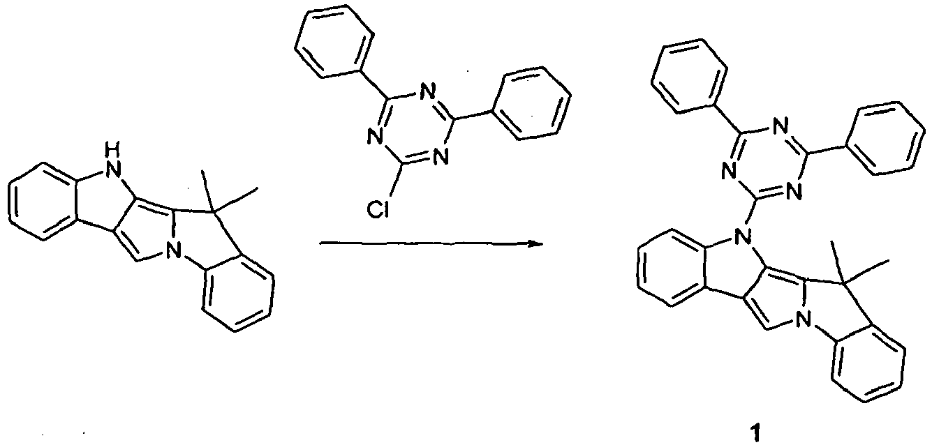
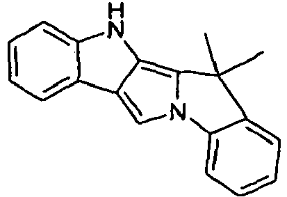
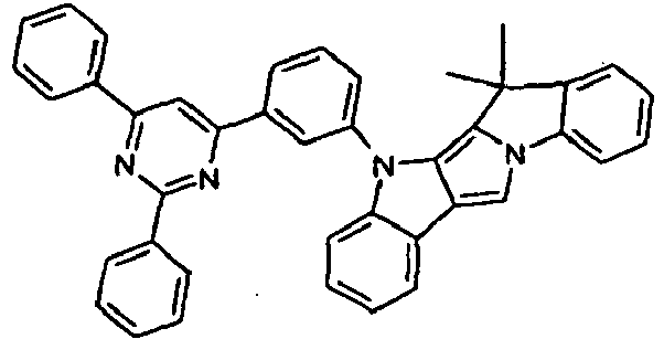
- 0 *C(*)(c1c2[n]c3ccccc3c2c[n]1-*1ccccc1)O Chemical compound *C(*)(c1c2[n]c3ccccc3c2c[n]1-*1ccccc1)O 0.000 description 5
- 150000001412 amines Chemical class 0.000 description 5
- 230000006872 improvement Effects 0.000 description 5
- 125000004433 nitrogen atom Chemical group N* 0.000 description 5
- 238000007639 printing Methods 0.000 description 5
- 239000000047 product Substances 0.000 description 5
- 239000004065 semiconductor Substances 0.000 description 5
- 229910052709 silver Inorganic materials 0.000 description 5
- 125000005504 styryl group Chemical group 0.000 description 5
- XLYOFNOQVPJJNP-UHFFFAOYSA-N water Substances O XLYOFNOQVPJJNP-UHFFFAOYSA-N 0.000 description 5
- DXBHBZVCASKNBY-UHFFFAOYSA-N 1,2-Benz(a)anthracene Chemical compound C1=CC=C2C3=CC4=CC=CC=C4C=C3C=CC2=C1 DXBHBZVCASKNBY-UHFFFAOYSA-N 0.000 description 4
- LFQSCWFLJHTTHZ-UHFFFAOYSA-N Ethanol Chemical compound CCO LFQSCWFLJHTTHZ-UHFFFAOYSA-N 0.000 description 4
- UFWIBTONFRDIAS-UHFFFAOYSA-N Naphthalene Chemical compound C1=CC=CC2=CC=CC=C21 UFWIBTONFRDIAS-UHFFFAOYSA-N 0.000 description 4
- MOFINMJRLYEONQ-UHFFFAOYSA-N [N].C=1C=CNC=1 Chemical group [N].C=1C=CNC=1 MOFINMJRLYEONQ-UHFFFAOYSA-N 0.000 description 4
- GVEPBJHOBDJJJI-UHFFFAOYSA-N fluoranthrene Natural products C1=CC(C2=CC=CC=C22)=C3C2=CC=CC3=C1 GVEPBJHOBDJJJI-UHFFFAOYSA-N 0.000 description 4
- 238000009472 formulation Methods 0.000 description 4
- 229910052697 platinum Inorganic materials 0.000 description 4
- 238000002360 preparation method Methods 0.000 description 4
- 239000011541 reaction mixture Substances 0.000 description 4
- 238000007363 ring formation reaction Methods 0.000 description 4
- UWRZIZXBOLBCON-UHFFFAOYSA-N 2-phenylethenamine Chemical class NC=CC1=CC=CC=C1 UWRZIZXBOLBCON-UHFFFAOYSA-N 0.000 description 3
- MMKNEELMYOLXLK-UHFFFAOYSA-N 4-(2-bromophenyl)-2,6-diphenylpyrimidine Chemical compound BrC1=CC=CC=C1C1=CC(C=2C=CC=CC=2)=NC(C=2C=CC=CC=2)=N1 MMKNEELMYOLXLK-UHFFFAOYSA-N 0.000 description 3
- UHOVQNZJYSORNB-UHFFFAOYSA-N Benzene Chemical compound C1=CC=CC=C1 UHOVQNZJYSORNB-UHFFFAOYSA-N 0.000 description 3
- OKKJLVBELUTLKV-UHFFFAOYSA-N Methanol Chemical compound OC OKKJLVBELUTLKV-UHFFFAOYSA-N 0.000 description 3
- ZMXDDKWLCZADIW-UHFFFAOYSA-N N,N-Dimethylformamide Chemical compound CN(C)C=O ZMXDDKWLCZADIW-UHFFFAOYSA-N 0.000 description 3
- KWYUFKZDYYNOTN-UHFFFAOYSA-M Potassium hydroxide Chemical compound [OH-].[K+] KWYUFKZDYYNOTN-UHFFFAOYSA-M 0.000 description 3
- BQCADISMDOOEFD-UHFFFAOYSA-N Silver Chemical compound [Ag] BQCADISMDOOEFD-UHFFFAOYSA-N 0.000 description 3
- HEMHJVSKTPXQMS-UHFFFAOYSA-M Sodium hydroxide Chemical compound [OH-].[Na+] HEMHJVSKTPXQMS-UHFFFAOYSA-M 0.000 description 3
- 229910052784 alkaline earth metal Inorganic materials 0.000 description 3
- 229910052782 aluminium Inorganic materials 0.000 description 3
- 150000004982 aromatic amines Chemical class 0.000 description 3
- 238000006243 chemical reaction Methods 0.000 description 3
- 229940125904 compound 1 Drugs 0.000 description 3
- 238000001816 cooling Methods 0.000 description 3
- 150000004985 diamines Chemical class 0.000 description 3
- 125000004986 diarylamino group Chemical group 0.000 description 3
- NPBOYYXEOTUPAN-UHFFFAOYSA-N diethyl 2-phenylpyrrolo[3,4-b]indole-3,4-dicarboxylate Chemical compound C1=C2C3=CC=CC=C3N(C(=O)OCC)C2=C(C(=O)OCC)N1C1=CC=CC=C1 NPBOYYXEOTUPAN-UHFFFAOYSA-N 0.000 description 3
- 125000005842 heteroatom Chemical group 0.000 description 3
- RAXXELZNTBOGNW-UHFFFAOYSA-N imidazole Natural products C1=CNC=N1 RAXXELZNTBOGNW-UHFFFAOYSA-N 0.000 description 3
- PZOUSPYUWWUPPK-UHFFFAOYSA-N indole Natural products CC1=CC=CC2=C1C=CN2 PZOUSPYUWWUPPK-UHFFFAOYSA-N 0.000 description 3
- RKJUIXBNRJVNHR-UHFFFAOYSA-N indolenine Natural products C1=CC=C2CC=NC2=C1 RKJUIXBNRJVNHR-UHFFFAOYSA-N 0.000 description 3
- 239000011229 interlayer Substances 0.000 description 3
- 229910052741 iridium Inorganic materials 0.000 description 3
- GKOZUEZYRPOHIO-UHFFFAOYSA-N iridium atom Chemical compound [Ir] GKOZUEZYRPOHIO-UHFFFAOYSA-N 0.000 description 3
- 150000002576 ketones Chemical class 0.000 description 3
- 239000008204 material by function Substances 0.000 description 3
- 229910052757 nitrogen Inorganic materials 0.000 description 3
- 239000012074 organic phase Substances 0.000 description 3
- 125000001997 phenyl group Chemical group [H]C1=C([H])C([H])=C(*)C([H])=C1[H] 0.000 description 3
- 125000000168 pyrrolyl group Chemical group 0.000 description 3
- 239000004332 silver Substances 0.000 description 3
- 239000007787 solid Substances 0.000 description 3
- 125000005259 triarylamine group Chemical group 0.000 description 3
- ICPSWZFVWAPUKF-UHFFFAOYSA-N 1,1'-spirobi[fluorene] Chemical class C1=CC=C2C=C3C4(C=5C(C6=CC=CC=C6C=5)=CC=C4)C=CC=C3C2=C1 ICPSWZFVWAPUKF-UHFFFAOYSA-N 0.000 description 2
- FCEHBMOGCRZNNI-UHFFFAOYSA-N 1-benzothiophene Chemical compound C1=CC=C2SC=CC2=C1 FCEHBMOGCRZNNI-UHFFFAOYSA-N 0.000 description 2
- 238000005160 1H NMR spectroscopy Methods 0.000 description 2
- YBYIRNPNPLQARY-UHFFFAOYSA-N 1H-indene Chemical compound C1=CC=C2CC=CC2=C1 YBYIRNPNPLQARY-UHFFFAOYSA-N 0.000 description 2
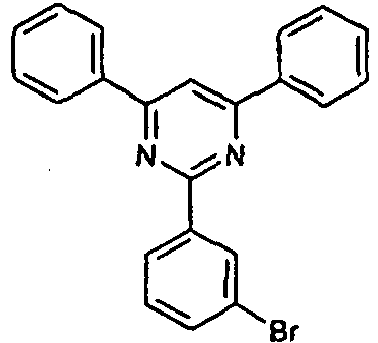
- BYDMGWHTARYHKO-UHFFFAOYSA-N 2-(3-bromophenyl)-4,6-diphenylpyrimidine Chemical compound BrC1=CC=CC(C=2N=C(C=C(N=2)C=2C=CC=CC=2)C=2C=CC=CC=2)=C1 BYDMGWHTARYHKO-UHFFFAOYSA-N 0.000 description 2
- DLXBSWIBLRUGFU-UHFFFAOYSA-N 4-(3,5-dibromophenyl)-2,6-diphenylpyrimidine Chemical compound BrC1=CC(Br)=CC(C=2N=C(N=C(C=2)C=2C=CC=CC=2)C=2C=CC=CC=2)=C1 DLXBSWIBLRUGFU-UHFFFAOYSA-N 0.000 description 2
- UJOBWOGCFQCDNV-UHFFFAOYSA-N 9H-carbazole Chemical compound C1=CC=C2C3=CC=CC=C3NC2=C1 UJOBWOGCFQCDNV-UHFFFAOYSA-N 0.000 description 2
- IJGRMHOSHXDMSA-UHFFFAOYSA-N Atomic nitrogen Chemical compound N#N IJGRMHOSHXDMSA-UHFFFAOYSA-N 0.000 description 2
- 102100036305 C-C chemokine receptor type 8 Human genes 0.000 description 2
- RYGMFSIKBFXOCR-UHFFFAOYSA-N Copper Chemical compound [Cu] RYGMFSIKBFXOCR-UHFFFAOYSA-N 0.000 description 2
- 101000837299 Euglena gracilis Trans-2-enoyl-CoA reductase Proteins 0.000 description 2
- YLQBMQCUIZJEEH-UHFFFAOYSA-N Furan Chemical compound C=1C=COC=1 YLQBMQCUIZJEEH-UHFFFAOYSA-N 0.000 description 2
- 101000716063 Homo sapiens C-C chemokine receptor type 8 Proteins 0.000 description 2
- AFVFQIVMOAPDHO-UHFFFAOYSA-N Methanesulfonic acid Chemical compound CS(O)(=O)=O AFVFQIVMOAPDHO-UHFFFAOYSA-N 0.000 description 2
- KDLHZDBZIXYQEI-UHFFFAOYSA-N Palladium Chemical compound [Pd] KDLHZDBZIXYQEI-UHFFFAOYSA-N 0.000 description 2
- URLKBWYHVLBVBO-UHFFFAOYSA-N Para-Xylene Chemical group CC1=CC=C(C)C=C1 URLKBWYHVLBVBO-UHFFFAOYSA-N 0.000 description 2
- KAESVJOAVNADME-UHFFFAOYSA-N Pyrrole Chemical compound C=1C=CNC=1 KAESVJOAVNADME-UHFFFAOYSA-N 0.000 description 2
- SMWDFEZZVXVKRB-UHFFFAOYSA-N Quinoline Chemical compound N1=CC=CC2=CC=CC=C21 SMWDFEZZVXVKRB-UHFFFAOYSA-N 0.000 description 2
- VYPSYNLAJGMNEJ-UHFFFAOYSA-N Silicium dioxide Chemical compound O=[Si]=O VYPSYNLAJGMNEJ-UHFFFAOYSA-N 0.000 description 2
- YTPLMLYBLZKORZ-UHFFFAOYSA-N Thiophene Chemical compound C=1C=CSC=1 YTPLMLYBLZKORZ-UHFFFAOYSA-N 0.000 description 2
- 150000001340 alkali metals Chemical class 0.000 description 2
- 150000001342 alkaline earth metals Chemical class 0.000 description 2
- 125000002947 alkylene group Chemical group 0.000 description 2
- 125000005577 anthracene group Chemical group 0.000 description 2
- 125000005264 aryl amine group Chemical group 0.000 description 2
- 125000001769 aryl amino group Chemical group 0.000 description 2
- 150000001642 boronic acid derivatives Chemical class 0.000 description 2
- WDECIBYCCFPHNR-UHFFFAOYSA-N chrysene Chemical compound C1=CC=CC2=CC=C3C4=CC=CC=C4C=CC3=C21 WDECIBYCCFPHNR-UHFFFAOYSA-N 0.000 description 2
- 238000004440 column chromatography Methods 0.000 description 2
- 229910052802 copper Inorganic materials 0.000 description 2
- 239000010949 copper Substances 0.000 description 2
- OPQARKPSCNTWTJ-UHFFFAOYSA-L copper(ii) acetate Chemical compound [Cu+2].CC([O-])=O.CC([O-])=O OPQARKPSCNTWTJ-UHFFFAOYSA-L 0.000 description 2
- 238000005859 coupling reaction Methods 0.000 description 2
- 230000002950 deficient Effects 0.000 description 2
- DHQSCKWFNRWGFF-UHFFFAOYSA-N diethyl 2h-pyrrolo[3,4-b]indole-3,4-dicarboxylate Chemical compound C1=CC=C2N(C(=O)OCC)C3=C(C(=O)OCC)NC=C3C2=C1 DHQSCKWFNRWGFF-UHFFFAOYSA-N 0.000 description 2
- 239000006185 dispersion Substances 0.000 description 2
- 238000001194 electroluminescence spectrum Methods 0.000 description 2
- 238000005516 engineering process Methods 0.000 description 2
- MCLNXGSCOLQUPS-UHFFFAOYSA-N ethyl 2-phenyl-4h-pyrrolo[3,4-b]indole-3-carboxylate Chemical compound C1=C(C2=CC=CC=C2N2)C2=C(C(=O)OCC)N1C1=CC=CC=C1 MCLNXGSCOLQUPS-UHFFFAOYSA-N 0.000 description 2
- 239000011521 glass Substances 0.000 description 2
- 230000009477 glass transition Effects 0.000 description 2
- 229910052737 gold Inorganic materials 0.000 description 2
- 239000010931 gold Substances 0.000 description 2
- WUNJCKOTXFSWBK-UHFFFAOYSA-N indeno[2,1-a]carbazole Chemical compound C1=CC=C2C=C3C4=NC5=CC=CC=C5C4=CC=C3C2=C1 WUNJCKOTXFSWBK-UHFFFAOYSA-N 0.000 description 2
- AMGQUBHHOARCQH-UHFFFAOYSA-N indium;oxotin Chemical compound [In].[Sn]=O AMGQUBHHOARCQH-UHFFFAOYSA-N 0.000 description 2
- 239000011261 inert gas Substances 0.000 description 2
- 238000007641 inkjet printing Methods 0.000 description 2
- AWJUIBRHMBBTKR-UHFFFAOYSA-N isoquinoline Chemical compound C1=NC=CC2=CC=CC=C21 AWJUIBRHMBBTKR-UHFFFAOYSA-N 0.000 description 2
- 229910052749 magnesium Inorganic materials 0.000 description 2
- 239000011777 magnesium Substances 0.000 description 2
- 238000004519 manufacturing process Methods 0.000 description 2
- 239000011368 organic material Substances 0.000 description 2
- MPQXHAGKBWFSNV-UHFFFAOYSA-N oxidophosphanium Chemical class [PH3]=O MPQXHAGKBWFSNV-UHFFFAOYSA-N 0.000 description 2
- YNPNZTXNASCQKK-UHFFFAOYSA-N phenanthrene Chemical compound C1=CC=C2C3=CC=CC=C3C=CC2=C1 YNPNZTXNASCQKK-UHFFFAOYSA-N 0.000 description 2
- HXITXNWTGFUOAU-UHFFFAOYSA-N phenylboronic acid Chemical compound OB(O)C1=CC=CC=C1 HXITXNWTGFUOAU-UHFFFAOYSA-N 0.000 description 2
- 238000012545 processing Methods 0.000 description 2
- 230000001681 protective effect Effects 0.000 description 2
- 238000000746 purification Methods 0.000 description 2
- 150000005592 pyrroloindoles Chemical class 0.000 description 2
- 239000000741 silica gel Substances 0.000 description 2
- 229910002027 silica gel Inorganic materials 0.000 description 2
- 239000002904 solvent Substances 0.000 description 2
- 238000004528 spin coating Methods 0.000 description 2
- 238000005092 sublimation method Methods 0.000 description 2
- 239000000126 substance Substances 0.000 description 2
- 238000006467 substitution reaction Methods 0.000 description 2
- 239000000758 substrate Substances 0.000 description 2
- 150000003462 sulfoxides Chemical class 0.000 description 2
- 229930192474 thiophene Natural products 0.000 description 2
- 150000003918 triazines Chemical class 0.000 description 2
- BWHDROKFUHTORW-UHFFFAOYSA-N tritert-butylphosphane Chemical compound CC(C)(C)P(C(C)(C)C)C(C)(C)C BWHDROKFUHTORW-UHFFFAOYSA-N 0.000 description 2
- HBENZIXOGRCSQN-VQWWACLZSA-N (1S,2S,6R,14R,15R,16R)-5-(cyclopropylmethyl)-16-[(2S)-2-hydroxy-3,3-dimethylpentan-2-yl]-15-methoxy-13-oxa-5-azahexacyclo[13.2.2.12,8.01,6.02,14.012,20]icosa-8(20),9,11-trien-11-ol Chemical compound N1([C@@H]2CC=3C4=C(C(=CC=3)O)O[C@H]3[C@@]5(OC)CC[C@@]2([C@@]43CC1)C[C@@H]5[C@](C)(O)C(C)(C)CC)CC1CC1 HBENZIXOGRCSQN-VQWWACLZSA-N 0.000 description 1
- PHDIJLFSKNMCMI-ITGJKDDRSA-N (3R,4S,5R,6R)-6-(hydroxymethyl)-4-(8-quinolin-6-yloxyoctoxy)oxane-2,3,5-triol Chemical compound OC[C@@H]1[C@H]([C@@H]([C@H](C(O1)O)O)OCCCCCCCCOC=1C=C2C=CC=NC2=CC=1)O PHDIJLFSKNMCMI-ITGJKDDRSA-N 0.000 description 1
- UHXOHPVVEHBKKT-UHFFFAOYSA-N 1-(2,2-diphenylethenyl)-4-[4-(2,2-diphenylethenyl)phenyl]benzene Chemical compound C=1C=C(C=2C=CC(C=C(C=3C=CC=CC=3)C=3C=CC=CC=3)=CC=2)C=CC=1C=C(C=1C=CC=CC=1)C1=CC=CC=C1 UHXOHPVVEHBKKT-UHFFFAOYSA-N 0.000 description 1
- IERDDDBDINUYCD-UHFFFAOYSA-N 1-[4-[4-(9h-carbazol-1-yl)phenyl]phenyl]-9h-carbazole Chemical group C12=CC=CC=C2NC2=C1C=CC=C2C(C=C1)=CC=C1C(C=C1)=CC=C1C1=C2NC3=CC=CC=C3C2=CC=C1 IERDDDBDINUYCD-UHFFFAOYSA-N 0.000 description 1
- LPHIYKWSEYTCLW-UHFFFAOYSA-N 1h-azaborole Chemical compound N1B=CC=C1 LPHIYKWSEYTCLW-UHFFFAOYSA-N 0.000 description 1
- FQJRASYPHMTCEG-UHFFFAOYSA-N 2-(2-phenyl-4h-pyrrolo[3,4-b]indol-3-yl)propan-2-ol Chemical compound C1=C(C2=CC=CC=C2N2)C2=C(C(C)(O)C)N1C1=CC=CC=C1 FQJRASYPHMTCEG-UHFFFAOYSA-N 0.000 description 1
- OSRSESUYXSEFCS-UHFFFAOYSA-N 2-(3,5-dibromophenyl)-4,6-diphenylpyrimidine Chemical compound BrC1=CC(Br)=CC(C=2N=C(C=C(N=2)C=2C=CC=CC=2)C=2C=CC=CC=2)=C1 OSRSESUYXSEFCS-UHFFFAOYSA-N 0.000 description 1
- DDGPPAMADXTGTN-UHFFFAOYSA-N 2-chloro-4,6-diphenyl-1,3,5-triazine Chemical compound N=1C(Cl)=NC(C=2C=CC=CC=2)=NC=1C1=CC=CC=C1 DDGPPAMADXTGTN-UHFFFAOYSA-N 0.000 description 1
- VHMICKWLTGFITH-UHFFFAOYSA-N 2H-isoindole Chemical compound C1=CC=CC2=CNC=C21 VHMICKWLTGFITH-UHFFFAOYSA-N 0.000 description 1
- OLPPSDMJGDTGJV-UHFFFAOYSA-N 3-(2-bromophenyl)-1-phenylprop-2-en-1-one Chemical compound BrC1=CC=CC=C1C=CC(=O)C1=CC=CC=C1 OLPPSDMJGDTGJV-UHFFFAOYSA-N 0.000 description 1
- MOMMWYBOMWAMND-UHFFFAOYSA-N 4-(3,5-dibromophenyl)-4,6-diphenyl-1h-pyrimidine Chemical compound BrC1=CC(Br)=CC(C2(C=C(N=CN2)C=2C=CC=CC=2)C=2C=CC=CC=2)=C1 MOMMWYBOMWAMND-UHFFFAOYSA-N 0.000 description 1
- MEJUPAUFPRYODM-UHFFFAOYSA-N 4-(3-bromophenyl)-4,6-diphenyl-1h-pyrimidine Chemical compound BrC1=CC=CC(C2(C=C(N=CN2)C=2C=CC=CC=2)C=2C=CC=CC=2)=C1 MEJUPAUFPRYODM-UHFFFAOYSA-N 0.000 description 1
- HIHOEGPXVVKJPP-JTQLQIEISA-N 5-fluoro-2-[[(1s)-1-(5-fluoropyridin-2-yl)ethyl]amino]-6-[(5-methyl-1h-pyrazol-3-yl)amino]pyridine-3-carbonitrile Chemical compound N([C@@H](C)C=1N=CC(F)=CC=1)C(C(=CC=1F)C#N)=NC=1NC=1C=C(C)NN=1 HIHOEGPXVVKJPP-JTQLQIEISA-N 0.000 description 1
- YNQTWUKZCHPALP-UHFFFAOYSA-N 7,9-dimethyl-5-phenyl-7h-indeno[2,1-b]carbazole Chemical compound C1=C2C(C)C3=CC(C)=CC=C3C2=CC(C2=CC=CC=C22)=C1N2C1=CC=CC=C1 YNQTWUKZCHPALP-UHFFFAOYSA-N 0.000 description 1
- 229910001316 Ag alloy Inorganic materials 0.000 description 1
- 229910016036 BaF 2 Inorganic materials 0.000 description 1
- 238000007125 Buchwald synthesis reaction Methods 0.000 description 1
- 238000006443 Buchwald-Hartwig cross coupling reaction Methods 0.000 description 1
- MVFRRKHFFMHOEZ-UHFFFAOYSA-N C1=CC=C2N(C(=O)OC)C3=C(C(=O)OC)NC=C3C2=C1 Chemical compound C1=CC=C2N(C(=O)OC)C3=C(C(=O)OC)NC=C3C2=C1 MVFRRKHFFMHOEZ-UHFFFAOYSA-N 0.000 description 1
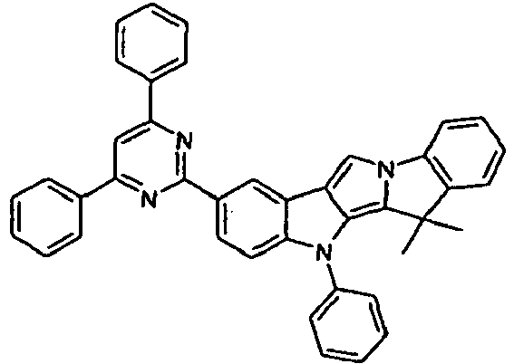
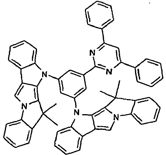
- GGDUKPPQBXMVJC-UHFFFAOYSA-N CC(C)(c(cccc1)c1-[n]1c(-c2ccccc2)c2c3cc(-[n]4c(cccc5)c5c5c4cccc5)ccc33)c1c2[n]3-c1ccccc1 Chemical compound CC(C)(c(cccc1)c1-[n]1c(-c2ccccc2)c2c3cc(-[n]4c(cccc5)c5c5c4cccc5)ccc33)c1c2[n]3-c1ccccc1 GGDUKPPQBXMVJC-UHFFFAOYSA-N 0.000 description 1
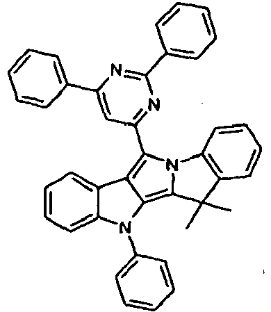
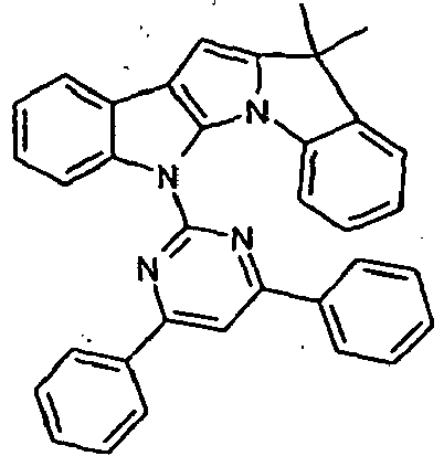
- RLHMAABSIXITJC-UHFFFAOYSA-N CC(C)(c(cccc1)c1-[n]1c(-c2nc(-c3ccccc3)cc(-c3ccccc3)n2)c2c3ccccc33)c1c2[n]3-c1ccccc1 Chemical compound CC(C)(c(cccc1)c1-[n]1c(-c2nc(-c3ccccc3)cc(-c3ccccc3)n2)c2c3ccccc33)c1c2[n]3-c1ccccc1 RLHMAABSIXITJC-UHFFFAOYSA-N 0.000 description 1
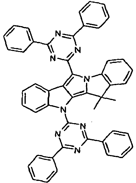
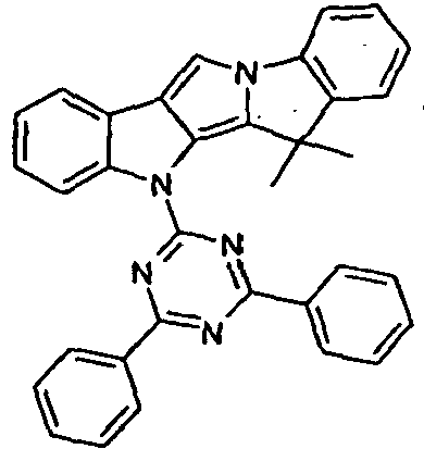
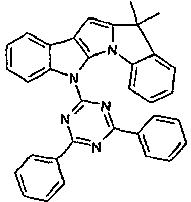
- UXQUZQRUTTXASQ-UHFFFAOYSA-N CC(C)(c(cccc1)c1-[n]1c(-c2nc(-c3ccccc3)nc(-c3ccccc3)n2)c2c3ccccc33)c1c2[n]3-c1nc(-c2ccccc2)nc(-c2ccccc2)n1 Chemical compound CC(C)(c(cccc1)c1-[n]1c(-c2nc(-c3ccccc3)nc(-c3ccccc3)n2)c2c3ccccc33)c1c2[n]3-c1nc(-c2ccccc2)nc(-c2ccccc2)n1 UXQUZQRUTTXASQ-UHFFFAOYSA-N 0.000 description 1
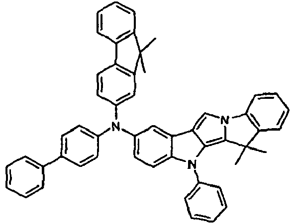
- LFDDRYLOAFBSBB-UHFFFAOYSA-N CC(C)(c(cccc1)c1-[n]1cc2c3c4ccc(N(c5ccccc5)c5c(cccc6)c6ccc5)c3)c1c2[n]4-c1ccccc1 Chemical compound CC(C)(c(cccc1)c1-[n]1cc2c3c4ccc(N(c5ccccc5)c5c(cccc6)c6ccc5)c3)c1c2[n]4-c1ccccc1 LFDDRYLOAFBSBB-UHFFFAOYSA-N 0.000 description 1
- ZKINTKGXRCMHCM-UHFFFAOYSA-N CC(C)(c(cccc1)c1-[n]1cc2c3cc(N(c(cc4)ccc4-c4ccccc4)c(cc4)ccc4-c4ccccc4)ccc33)c1c2[n]3-c1ccccc1 Chemical compound CC(C)(c(cccc1)c1-[n]1cc2c3cc(N(c(cc4)ccc4-c4ccccc4)c(cc4)ccc4-c4ccccc4)ccc33)c1c2[n]3-c1ccccc1 ZKINTKGXRCMHCM-UHFFFAOYSA-N 0.000 description 1
- XQIUBMOKQKAFIJ-UHFFFAOYSA-N CC(C)(c(cccc1)c1-[n]1cc2c3ccccc33)c1c2[n]3-c(cccc1)c1-c1nc(-c2ccccc2)nc(-c2ccccc2)c1 Chemical compound CC(C)(c(cccc1)c1-[n]1cc2c3ccccc33)c1c2[n]3-c(cccc1)c1-c1nc(-c2ccccc2)nc(-c2ccccc2)c1 XQIUBMOKQKAFIJ-UHFFFAOYSA-N 0.000 description 1
- JQDVQGMIEWGJQA-UHFFFAOYSA-N CC(C)(c(cccc1)c1-[n]1cc2c3ccccc33)c1c2[n]3-c1cc(-[n](c(cccc2)c2c2c3)c2c(C2(C)C)[n]3-c3c2cccc3)cc(-[n](c(cccc2)c2c2c3)c2c(C2(C)C)[n]3-c3c2cccc3)c1 Chemical compound CC(C)(c(cccc1)c1-[n]1cc2c3ccccc33)c1c2[n]3-c1cc(-[n](c(cccc2)c2c2c3)c2c(C2(C)C)[n]3-c3c2cccc3)cc(-[n](c(cccc2)c2c2c3)c2c(C2(C)C)[n]3-c3c2cccc3)c1 JQDVQGMIEWGJQA-UHFFFAOYSA-N 0.000 description 1
- WFRLQHQOTFFPGZ-UHFFFAOYSA-N CC(C)(c(cccc1)c1-[n]1cc2c3ccccc33)c1c2[n]3-c1cc(-c2nc(-c3ccccc3)nc(-c3ccccc3)c2)cc(-[n](c(cccc2)c2c2c3)c2c2[n]3-c3ccccc3C2(C)C)c1 Chemical compound CC(C)(c(cccc1)c1-[n]1cc2c3ccccc33)c1c2[n]3-c1cc(-c2nc(-c3ccccc3)nc(-c3ccccc3)c2)cc(-[n](c(cccc2)c2c2c3)c2c2[n]3-c3ccccc3C2(C)C)c1 WFRLQHQOTFFPGZ-UHFFFAOYSA-N 0.000 description 1
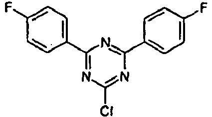
- GSSKTKVXRFWWFL-UHFFFAOYSA-N CC(C)(c(cccc1)c1-[n]1cc2c3ccccc33)c1c2[n]3-c1nc(-c(cc2)ccc2F)nc(-c(cc2)ccc2F)n1 Chemical compound CC(C)(c(cccc1)c1-[n]1cc2c3ccccc33)c1c2[n]3-c1nc(-c(cc2)ccc2F)nc(-c(cc2)ccc2F)n1 GSSKTKVXRFWWFL-UHFFFAOYSA-N 0.000 description 1
- YIBIKQURMKREMA-UHFFFAOYSA-N CC(C)(c1c2)c(cccc3)c3-[n]1c1c2c(cccc2)c2[n]1-c(cc1)ccc1-c(cc1)ccc1N(c(cc1)ccc1-c1ccccc1)c(cc1)cc2c1-c1ccccc1C2(C)C Chemical compound CC(C)(c1c2)c(cccc3)c3-[n]1c1c2c(cccc2)c2[n]1-c(cc1)ccc1-c(cc1)ccc1N(c(cc1)ccc1-c1ccccc1)c(cc1)cc2c1-c1ccccc1C2(C)C YIBIKQURMKREMA-UHFFFAOYSA-N 0.000 description 1
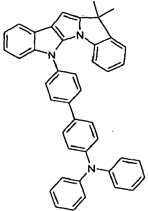
- RGICDZMFXDWIKV-UHFFFAOYSA-N CC(C)(c1c2)c(cccc3)c3-[n]1c1c2c(cccc2)c2[n]1-c(cc1)ccc1-c(cc1)ccc1N(c1ccccc1)c1ccccc1 Chemical compound CC(C)(c1c2)c(cccc3)c3-[n]1c1c2c(cccc2)c2[n]1-c(cc1)ccc1-c(cc1)ccc1N(c1ccccc1)c1ccccc1 RGICDZMFXDWIKV-UHFFFAOYSA-N 0.000 description 1
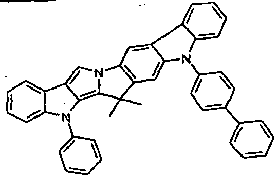
- HILNFEVMEDICFK-UHFFFAOYSA-N CC(C)(c1c2)c3ccccc3-[n]1c1c2c(cccc2)c2[n]1-c(cc1)cc(c2c3cccc2)c1[n]3-c1ccccc1 Chemical compound CC(C)(c1c2)c3ccccc3-[n]1c1c2c(cccc2)c2[n]1-c(cc1)cc(c2c3cccc2)c1[n]3-c1ccccc1 HILNFEVMEDICFK-UHFFFAOYSA-N 0.000 description 1
- JBIMNHBKUOVPSV-UHFFFAOYSA-N CC(C)(c1c2)c3ccccc3-[n]1c1c2c(cccc2)c2[n]1-c(cc1)ccc1-c(cc1)ccc1-[n]1c(cccc2)c2c2c1cccc2 Chemical compound CC(C)(c1c2)c3ccccc3-[n]1c1c2c(cccc2)c2[n]1-c(cc1)ccc1-c(cc1)ccc1-[n]1c(cccc2)c2c2c1cccc2 JBIMNHBKUOVPSV-UHFFFAOYSA-N 0.000 description 1
- XCZPEKWJEZMAKW-UHFFFAOYSA-N CC(C)(c1c2)c3ccccc3-[n]1c1c2c(cccc2)c2[n]1-c(cc1C2(C)C)ccc1-c(cc1)c2cc1N(c1ccccc1)c1ccccc1 Chemical compound CC(C)(c1c2)c3ccccc3-[n]1c1c2c(cccc2)c2[n]1-c(cc1C2(C)C)ccc1-c(cc1)c2cc1N(c1ccccc1)c1ccccc1 XCZPEKWJEZMAKW-UHFFFAOYSA-N 0.000 description 1
- XLVJHQRZLDNLOR-UHFFFAOYSA-N CC(C)(c1cc(-[n]2c3ccccc3c3c2cccc3)ccc1-[n]1cc2c3ccccc33)c1c2[n]3-c1ccccc1 Chemical compound CC(C)(c1cc(-[n]2c3ccccc3c3c2cccc3)ccc1-[n]1cc2c3ccccc33)c1c2[n]3-c1ccccc1 XLVJHQRZLDNLOR-UHFFFAOYSA-N 0.000 description 1
- IOCRYYSIEMJEJP-UHFFFAOYSA-N CC(C)(c1ccccc1-[n]1cc2-c3ccccc33)c1c2S3(=O)=O Chemical compound CC(C)(c1ccccc1-[n]1cc2-c3ccccc33)c1c2S3(=O)=O IOCRYYSIEMJEJP-UHFFFAOYSA-N 0.000 description 1
- APALLSAYVNKYNA-UHFFFAOYSA-N CC(C)(c1ccccc1-[n]1cc2c3ccccc33)c1c2[n]3-c1cc(-c2ccccc2)cc(-c2ccccc2)c1 Chemical compound CC(C)(c1ccccc1-[n]1cc2c3ccccc33)c1c2[n]3-c1cc(-c2ccccc2)cc(-c2ccccc2)c1 APALLSAYVNKYNA-UHFFFAOYSA-N 0.000 description 1
- IJAFKBFJSKEEKI-UHFFFAOYSA-N CC(C)(c1ccccc1-[n]1cc2c3ccccc33)c1c2[n]3-c1cc(-c2nc(-c3ccccc3)nc(-c3ccccc3)c2)ccc1 Chemical compound CC(C)(c1ccccc1-[n]1cc2c3ccccc33)c1c2[n]3-c1cc(-c2nc(-c3ccccc3)nc(-c3ccccc3)c2)ccc1 IJAFKBFJSKEEKI-UHFFFAOYSA-N 0.000 description 1
- BPIFGBNVQWKAFT-UHFFFAOYSA-N CC(C)(c1ccccc1-[n]1cc2c3ccccc33)c1c2[n]3-c1nc(-c2c(C)cccc2)nc(-c2c(C)cccc2)n1 Chemical compound CC(C)(c1ccccc1-[n]1cc2c3ccccc33)c1c2[n]3-c1nc(-c2c(C)cccc2)nc(-c2c(C)cccc2)n1 BPIFGBNVQWKAFT-UHFFFAOYSA-N 0.000 description 1
- XZBTYGPSYWRRPP-UHFFFAOYSA-N CC1(C)c2c3[n](C4(C)C=CC=CC4)c4ccccc4c3c(N(c3ccccc3)c3ccccc3)[n]2-c2c1cccc2 Chemical compound CC1(C)c2c3[n](C4(C)C=CC=CC4)c4ccccc4c3c(N(c3ccccc3)c3ccccc3)[n]2-c2c1cccc2 XZBTYGPSYWRRPP-UHFFFAOYSA-N 0.000 description 1
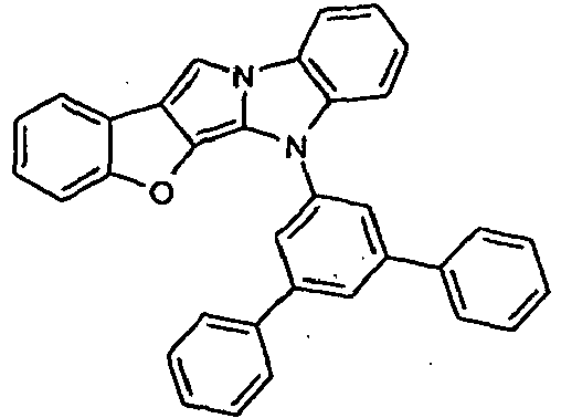
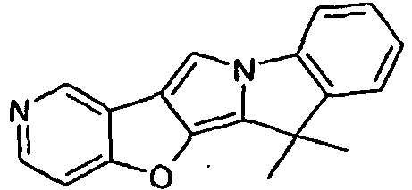
- ACAJCZQYIMCBIK-UHFFFAOYSA-N CC1(C)c2c3[o]c4ccncc4c3c[n]2-c2c1cccc2 Chemical compound CC1(C)c2c3[o]c4ccncc4c3c[n]2-c2c1cccc2 ACAJCZQYIMCBIK-UHFFFAOYSA-N 0.000 description 1
- KHKIQGKBQYZGBQ-UHFFFAOYSA-N CC1(C)c2c3[s]c4ccccc4c3c[n]2-c2c1cccc2 Chemical compound CC1(C)c2c3[s]c4ccccc4c3c[n]2-c2c1cccc2 KHKIQGKBQYZGBQ-UHFFFAOYSA-N 0.000 description 1
- ZAMOUSCENKQFHK-UHFFFAOYSA-N Chlorine atom Chemical compound [Cl] ZAMOUSCENKQFHK-UHFFFAOYSA-N 0.000 description 1
- 229910052693 Europium Inorganic materials 0.000 description 1
- 238000003547 Friedel-Crafts alkylation reaction Methods 0.000 description 1
- 229910018068 Li 2 O Inorganic materials 0.000 description 1
- 229910000861 Mg alloy Inorganic materials 0.000 description 1
- ZOKXTWBITQBERF-UHFFFAOYSA-N Molybdenum Chemical compound [Mo] ZOKXTWBITQBERF-UHFFFAOYSA-N 0.000 description 1
- 229920001609 Poly(3,4-ethylenedioxythiophene) Polymers 0.000 description 1
- 229920000265 Polyparaphenylene Polymers 0.000 description 1
- WTKZEGDFNFYCGP-UHFFFAOYSA-N Pyrazole Chemical compound C=1C=NNC=1 WTKZEGDFNFYCGP-UHFFFAOYSA-N 0.000 description 1
- KJTLSVCANCCWHF-UHFFFAOYSA-N Ruthenium Chemical compound [Ru] KJTLSVCANCCWHF-UHFFFAOYSA-N 0.000 description 1
- 229910052772 Samarium Inorganic materials 0.000 description 1
- BLRPTPMANUNPDV-UHFFFAOYSA-N Silane Chemical compound [SiH4] BLRPTPMANUNPDV-UHFFFAOYSA-N 0.000 description 1
- XBDYBAVJXHJMNQ-UHFFFAOYSA-N Tetrahydroanthracene Natural products C1=CC=C2C=C(CCCC3)C3=CC2=C1 XBDYBAVJXHJMNQ-UHFFFAOYSA-N 0.000 description 1
- 230000002378 acidificating effect Effects 0.000 description 1
- 239000003513 alkali Substances 0.000 description 1
- 229910052783 alkali metal Inorganic materials 0.000 description 1
- 229910001515 alkali metal fluoride Inorganic materials 0.000 description 1
- 229910001618 alkaline earth metal fluoride Inorganic materials 0.000 description 1
- 125000004450 alkenylene group Chemical group 0.000 description 1
- 229910045601 alloy Inorganic materials 0.000 description 1
- 239000000956 alloy Substances 0.000 description 1
- SRVFFFJZQVENJC-IHRRRGAJSA-N aloxistatin Chemical compound CCOC(=O)[C@H]1O[C@@H]1C(=O)N[C@@H](CC(C)C)C(=O)NCCC(C)C SRVFFFJZQVENJC-IHRRRGAJSA-N 0.000 description 1
- XAGFODPZIPBFFR-UHFFFAOYSA-N aluminium Chemical compound [Al] XAGFODPZIPBFFR-UHFFFAOYSA-N 0.000 description 1
- IMHBYKMAHXWHRP-UHFFFAOYSA-N anilazine Chemical compound ClC1=CC=CC=C1NC1=NC(Cl)=NC(Cl)=N1 IMHBYKMAHXWHRP-UHFFFAOYSA-N 0.000 description 1
- 239000010405 anode material Substances 0.000 description 1
- VVLCNWYWKSWJTG-UHFFFAOYSA-N anthracene-1,2-diamine Chemical compound C1=CC=CC2=CC3=C(N)C(N)=CC=C3C=C21 VVLCNWYWKSWJTG-UHFFFAOYSA-N 0.000 description 1
- 150000008365 aromatic ketones Chemical class 0.000 description 1
- 125000000732 arylene group Chemical group 0.000 description 1
- 229910052788 barium Inorganic materials 0.000 description 1
- RFRXIWQYSOIBDI-UHFFFAOYSA-N benzarone Chemical compound CCC=1OC2=CC=CC=C2C=1C(=O)C1=CC=C(O)C=C1 RFRXIWQYSOIBDI-UHFFFAOYSA-N 0.000 description 1
- QRUDEWIWKLJBPS-UHFFFAOYSA-N benzotriazole Chemical compound C1=CC=C2N[N][N]C2=C1 QRUDEWIWKLJBPS-UHFFFAOYSA-N 0.000 description 1
- 239000012964 benzotriazole Substances 0.000 description 1
- SNIABFMMCKVXSY-UHFFFAOYSA-N benzoylazanium;chloride Chemical compound Cl.NC(=O)C1=CC=CC=C1 SNIABFMMCKVXSY-UHFFFAOYSA-N 0.000 description 1
- ZADPBFCGQRWHPN-UHFFFAOYSA-N boronic acid Chemical compound OBO ZADPBFCGQRWHPN-UHFFFAOYSA-N 0.000 description 1
- 125000005620 boronic acid group Chemical group 0.000 description 1
- GDTBXPJZTBHREO-UHFFFAOYSA-N bromine Substances BrBr GDTBXPJZTBHREO-UHFFFAOYSA-N 0.000 description 1
- 125000001246 bromo group Chemical group Br* 0.000 description 1
- 229910052791 calcium Inorganic materials 0.000 description 1
- 125000000609 carbazolyl group Chemical group C1(=CC=CC=2C3=CC=CC=C3NC12)* 0.000 description 1
- 150000004649 carbonic acid derivatives Chemical class 0.000 description 1
- 239000012159 carrier gas Substances 0.000 description 1
- 238000012512 characterization method Methods 0.000 description 1
- 238000010549 co-Evaporation Methods 0.000 description 1
- 239000003086 colorant Substances 0.000 description 1
- 229940125782 compound 2 Drugs 0.000 description 1
- 239000000470 constituent Substances 0.000 description 1
- 150000001879 copper Chemical class 0.000 description 1
- 239000002537 cosmetic Substances 0.000 description 1
- 230000008878 coupling Effects 0.000 description 1
- 238000010168 coupling process Methods 0.000 description 1
- 239000013078 crystal Substances 0.000 description 1
- 238000000354 decomposition reaction Methods 0.000 description 1
- 150000007858 diazaphosphole derivatives Chemical class 0.000 description 1
- OGPBJKLSAFTDLK-UHFFFAOYSA-N europium atom Chemical compound [Eu] OGPBJKLSAFTDLK-UHFFFAOYSA-N 0.000 description 1
- 230000005284 excitation Effects 0.000 description 1
- 230000001747 exhibiting effect Effects 0.000 description 1
- 230000005669 field effect Effects 0.000 description 1
- RMBPEFMHABBEKP-UHFFFAOYSA-N fluorene Chemical compound C1=CC=C2C3=C[CH]C=CC3=CC2=C1 RMBPEFMHABBEKP-UHFFFAOYSA-N 0.000 description 1
- 125000001153 fluoro group Chemical group F* 0.000 description 1
- 229920001002 functional polymer Polymers 0.000 description 1
- 239000007789 gas Substances 0.000 description 1
- 238000007429 general method Methods 0.000 description 1
- PCHJSUWPFVWCPO-UHFFFAOYSA-N gold Chemical compound [Au] PCHJSUWPFVWCPO-UHFFFAOYSA-N 0.000 description 1
- 150000002367 halogens Chemical group 0.000 description 1
- 229930195733 hydrocarbon Natural products 0.000 description 1
- 150000002430 hydrocarbons Chemical class 0.000 description 1
- 229920006150 hyperbranched polyester Polymers 0.000 description 1
- 238000005286 illumination Methods 0.000 description 1
- 150000002469 indenes Chemical class 0.000 description 1
- PJULCNAVAGQLAT-UHFFFAOYSA-N indeno[2,1-a]fluorene Chemical class C1=CC=C2C=C3C4=CC5=CC=CC=C5C4=CC=C3C2=C1 PJULCNAVAGQLAT-UHFFFAOYSA-N 0.000 description 1
- 229910052738 indium Inorganic materials 0.000 description 1
- VVVPGLRKXQSQSZ-UHFFFAOYSA-N indolo[3,2-c]carbazole Chemical class C1=CC=CC2=NC3=C4C5=CC=CC=C5N=C4C=CC3=C21 VVVPGLRKXQSQSZ-UHFFFAOYSA-N 0.000 description 1
- PNDPGZBMCMUPRI-UHFFFAOYSA-N iodine Chemical group II PNDPGZBMCMUPRI-UHFFFAOYSA-N 0.000 description 1
- 229910052747 lanthanoid Inorganic materials 0.000 description 1
- 150000002602 lanthanoids Chemical class 0.000 description 1
- 239000007791 liquid phase Substances 0.000 description 1
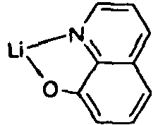
- IMKMFBIYHXBKRX-UHFFFAOYSA-M lithium;quinoline-2-carboxylate Chemical compound [Li+].C1=CC=CC2=NC(C(=O)[O-])=CC=C21 IMKMFBIYHXBKRX-UHFFFAOYSA-M 0.000 description 1
- 229910001092 metal group alloy Inorganic materials 0.000 description 1
- 229940098779 methanesulfonic acid Drugs 0.000 description 1
- DVSDBMFJEQPWNO-UHFFFAOYSA-N methyllithium Chemical compound C[Li] DVSDBMFJEQPWNO-UHFFFAOYSA-N 0.000 description 1
- 239000002480 mineral oil Substances 0.000 description 1
- 235000010446 mineral oil Nutrition 0.000 description 1
- 229910003455 mixed metal oxide Inorganic materials 0.000 description 1
- 239000002808 molecular sieve Substances 0.000 description 1
- 229910052750 molybdenum Inorganic materials 0.000 description 1
- 239000011733 molybdenum Substances 0.000 description 1
- QAPTWHXHEYAIKG-RCOXNQKVSA-N n-[(1r,2s,5r)-5-(tert-butylamino)-2-[(3s)-2-oxo-3-[[6-(trifluoromethyl)quinazolin-4-yl]amino]pyrrolidin-1-yl]cyclohexyl]acetamide Chemical compound CC(=O)N[C@@H]1C[C@H](NC(C)(C)C)CC[C@@H]1N1C(=O)[C@@H](NC=2C3=CC(=CC=C3N=CN=2)C(F)(F)F)CC1 QAPTWHXHEYAIKG-RCOXNQKVSA-N 0.000 description 1
- NIHNNTQXNPWCJQ-UHFFFAOYSA-N o-biphenylenemethane Natural products C1=CC=C2CC3=CC=CC=C3C2=C1 NIHNNTQXNPWCJQ-UHFFFAOYSA-N 0.000 description 1
- 238000007645 offset printing Methods 0.000 description 1
- 238000006384 oligomerization reaction Methods 0.000 description 1
- 230000003287 optical effect Effects 0.000 description 1
- 239000012044 organic layer Substances 0.000 description 1
- 239000003960 organic solvent Substances 0.000 description 1
- 150000002900 organolithium compounds Chemical class 0.000 description 1
- 229910052762 osmium Inorganic materials 0.000 description 1
- SYQBFIAQOQZEGI-UHFFFAOYSA-N osmium atom Chemical compound [Os] SYQBFIAQOQZEGI-UHFFFAOYSA-N 0.000 description 1
- 230000003647 oxidation Effects 0.000 description 1
- 238000007254 oxidation reaction Methods 0.000 description 1
- 229910052763 palladium Inorganic materials 0.000 description 1
- YJVFFLUZDVXJQI-UHFFFAOYSA-L palladium(ii) acetate Chemical compound [Pd+2].CC([O-])=O.CC([O-])=O YJVFFLUZDVXJQI-UHFFFAOYSA-L 0.000 description 1
- SLIUAWYAILUBJU-UHFFFAOYSA-N pentacene Chemical compound C1=CC=CC2=CC3=CC4=CC5=CC=CC=C5C=C4C=C3C=C21 SLIUAWYAILUBJU-UHFFFAOYSA-N 0.000 description 1
- 239000012071 phase Substances 0.000 description 1
- 238000005191 phase separation Methods 0.000 description 1
- 150000002987 phenanthrenes Chemical class 0.000 description 1
- 108091008695 photoreceptors Proteins 0.000 description 1
- 238000001126 phototherapy Methods 0.000 description 1
- 229920000137 polyphosphoric acid Polymers 0.000 description 1
- 230000008092 positive effect Effects 0.000 description 1
- 239000002244 precipitate Substances 0.000 description 1
- 125000006239 protecting group Chemical group 0.000 description 1
- BUAWIRPPAOOHKD-UHFFFAOYSA-N pyrene-1,2-diamine Chemical class C1=CC=C2C=CC3=C(N)C(N)=CC4=CC=C1C2=C43 BUAWIRPPAOOHKD-UHFFFAOYSA-N 0.000 description 1
- 238000010791 quenching Methods 0.000 description 1
- 230000005855 radiation Effects 0.000 description 1
- 239000000376 reactant Substances 0.000 description 1
- 239000012429 reaction media Substances 0.000 description 1
- 229920013730 reactive polymer Polymers 0.000 description 1
- 230000009467 reduction Effects 0.000 description 1
- 238000010992 reflux Methods 0.000 description 1
- 229910052702 rhenium Inorganic materials 0.000 description 1
- WUAPFZMCVAUBPE-UHFFFAOYSA-N rhenium atom Chemical compound [Re] WUAPFZMCVAUBPE-UHFFFAOYSA-N 0.000 description 1
- 229910052703 rhodium Inorganic materials 0.000 description 1
- 239000010948 rhodium Substances 0.000 description 1
- MHOVAHRLVXNVSD-UHFFFAOYSA-N rhodium atom Chemical compound [Rh] MHOVAHRLVXNVSD-UHFFFAOYSA-N 0.000 description 1
- 229910052707 ruthenium Inorganic materials 0.000 description 1
- 238000007650 screen-printing Methods 0.000 description 1
- 229910000077 silane Inorganic materials 0.000 description 1
- 239000010944 silver (metal) Substances 0.000 description 1
- URGAHOPLAPQHLN-UHFFFAOYSA-N sodium aluminosilicate Chemical compound [Na+].[Al+3].[O-][Si]([O-])=O.[O-][Si]([O-])=O URGAHOPLAPQHLN-UHFFFAOYSA-N 0.000 description 1
- 150000001629 stilbenes Chemical class 0.000 description 1
- 235000021286 stilbenes Nutrition 0.000 description 1
- 238000000859 sublimation Methods 0.000 description 1
- 230000008022 sublimation Effects 0.000 description 1
- 150000003457 sulfones Chemical class 0.000 description 1
- 239000000725 suspension Substances 0.000 description 1
- 238000001308 synthesis method Methods 0.000 description 1
- 150000003509 tertiary alcohols Chemical class 0.000 description 1
- IFLREYGFSNHWGE-UHFFFAOYSA-N tetracene Chemical compound C1=CC=CC2=CC3=CC4=CC=CC=C4C=C3C=C21 IFLREYGFSNHWGE-UHFFFAOYSA-N 0.000 description 1
- 238000001931 thermography Methods 0.000 description 1
- 239000010409 thin film Substances 0.000 description 1
- 150000003577 thiophenes Chemical class 0.000 description 1
- 238000010023 transfer printing Methods 0.000 description 1
- 150000003852 triazoles Chemical class 0.000 description 1
- SLGBZMMZGDRARJ-UHFFFAOYSA-N triphenylene Chemical compound C1=CC=C2C3=CC=CC=C3C3=CC=CC=C3C2=C1 SLGBZMMZGDRARJ-UHFFFAOYSA-N 0.000 description 1
- WFKWXMTUELFFGS-UHFFFAOYSA-N tungsten Chemical compound [W] WFKWXMTUELFFGS-UHFFFAOYSA-N 0.000 description 1
- 229910052721 tungsten Inorganic materials 0.000 description 1
- 239000010937 tungsten Substances 0.000 description 1
- 238000001947 vapour-phase growth Methods 0.000 description 1
- 229920002554 vinyl polymer Polymers 0.000 description 1
- 150000003751 zinc Chemical class 0.000 description 1
- YVTHLONGBIQYBO-UHFFFAOYSA-N zinc indium(3+) oxygen(2-) Chemical compound [O--].[Zn++].[In+3] YVTHLONGBIQYBO-UHFFFAOYSA-N 0.000 description 1
Classifications
-
- H—ELECTRICITY
- H10—SEMICONDUCTOR DEVICES; ELECTRIC SOLID-STATE DEVICES NOT OTHERWISE PROVIDED FOR
- H10K—ORGANIC ELECTRIC SOLID-STATE DEVICES
- H10K85/00—Organic materials used in the body or electrodes of devices covered by this subclass
- H10K85/60—Organic compounds having low molecular weight
- H10K85/649—Aromatic compounds comprising a hetero atom
- H10K85/657—Polycyclic condensed heteroaromatic hydrocarbons
- H10K85/6574—Polycyclic condensed heteroaromatic hydrocarbons comprising only oxygen in the heteroaromatic polycondensed ring system, e.g. cumarine dyes
-
- C—CHEMISTRY; METALLURGY
- C09—DYES; PAINTS; POLISHES; NATURAL RESINS; ADHESIVES; COMPOSITIONS NOT OTHERWISE PROVIDED FOR; APPLICATIONS OF MATERIALS NOT OTHERWISE PROVIDED FOR
- C09K—MATERIALS FOR MISCELLANEOUS APPLICATIONS, NOT PROVIDED FOR ELSEWHERE
- C09K11/00—Luminescent, e.g. electroluminescent, chemiluminescent materials
- C09K11/06—Luminescent, e.g. electroluminescent, chemiluminescent materials containing organic luminescent materials
-
- C—CHEMISTRY; METALLURGY
- C07—ORGANIC CHEMISTRY
- C07D—HETEROCYCLIC COMPOUNDS
- C07D471/00—Heterocyclic compounds containing nitrogen atoms as the only ring hetero atoms in the condensed system, at least one ring being a six-membered ring with one nitrogen atom, not provided for by groups C07D451/00 - C07D463/00
- C07D471/22—Heterocyclic compounds containing nitrogen atoms as the only ring hetero atoms in the condensed system, at least one ring being a six-membered ring with one nitrogen atom, not provided for by groups C07D451/00 - C07D463/00 in which the condensed systems contains four or more hetero rings
-
- C—CHEMISTRY; METALLURGY
- C07—ORGANIC CHEMISTRY
- C07D—HETEROCYCLIC COMPOUNDS
- C07D487/00—Heterocyclic compounds containing nitrogen atoms as the only ring hetero atoms in the condensed system, not provided for by groups C07D451/00 - C07D477/00
- C07D487/02—Heterocyclic compounds containing nitrogen atoms as the only ring hetero atoms in the condensed system, not provided for by groups C07D451/00 - C07D477/00 in which the condensed system contains two hetero rings
- C07D487/04—Ortho-condensed systems
-
- C—CHEMISTRY; METALLURGY
- C07—ORGANIC CHEMISTRY
- C07D—HETEROCYCLIC COMPOUNDS
- C07D487/00—Heterocyclic compounds containing nitrogen atoms as the only ring hetero atoms in the condensed system, not provided for by groups C07D451/00 - C07D477/00
- C07D487/12—Heterocyclic compounds containing nitrogen atoms as the only ring hetero atoms in the condensed system, not provided for by groups C07D451/00 - C07D477/00 in which the condensed system contains three hetero rings
- C07D487/14—Ortho-condensed systems
-
- C—CHEMISTRY; METALLURGY
- C07—ORGANIC CHEMISTRY
- C07D—HETEROCYCLIC COMPOUNDS
- C07D491/00—Heterocyclic compounds containing in the condensed ring system both one or more rings having oxygen atoms as the only ring hetero atoms and one or more rings having nitrogen atoms as the only ring hetero atoms, not provided for by groups C07D451/00 - C07D459/00, C07D463/00, C07D477/00 or C07D489/00
- C07D491/12—Heterocyclic compounds containing in the condensed ring system both one or more rings having oxygen atoms as the only ring hetero atoms and one or more rings having nitrogen atoms as the only ring hetero atoms, not provided for by groups C07D451/00 - C07D459/00, C07D463/00, C07D477/00 or C07D489/00 in which the condensed system contains three hetero rings
- C07D491/14—Ortho-condensed systems
-
- C—CHEMISTRY; METALLURGY
- C07—ORGANIC CHEMISTRY
- C07D—HETEROCYCLIC COMPOUNDS
- C07D495/00—Heterocyclic compounds containing in the condensed system at least one hetero ring having sulfur atoms as the only ring hetero atoms
- C07D495/12—Heterocyclic compounds containing in the condensed system at least one hetero ring having sulfur atoms as the only ring hetero atoms in which the condensed system contains three hetero rings
- C07D495/14—Ortho-condensed systems
-
- C—CHEMISTRY; METALLURGY
- C07—ORGANIC CHEMISTRY
- C07D—HETEROCYCLIC COMPOUNDS
- C07D498/00—Heterocyclic compounds containing in the condensed system at least one hetero ring having nitrogen and oxygen atoms as the only ring hetero atoms
- C07D498/12—Heterocyclic compounds containing in the condensed system at least one hetero ring having nitrogen and oxygen atoms as the only ring hetero atoms in which the condensed system contains three hetero rings
- C07D498/14—Ortho-condensed systems
-
- C—CHEMISTRY; METALLURGY
- C07—ORGANIC CHEMISTRY
- C07D—HETEROCYCLIC COMPOUNDS
- C07D513/00—Heterocyclic compounds containing in the condensed system at least one hetero ring having nitrogen and sulfur atoms as the only ring hetero atoms, not provided for in groups C07D463/00, C07D477/00 or C07D499/00 - C07D507/00
- C07D513/12—Heterocyclic compounds containing in the condensed system at least one hetero ring having nitrogen and sulfur atoms as the only ring hetero atoms, not provided for in groups C07D463/00, C07D477/00 or C07D499/00 - C07D507/00 in which the condensed system contains three hetero rings
- C07D513/14—Ortho-condensed systems
-
- C—CHEMISTRY; METALLURGY
- C07—ORGANIC CHEMISTRY
- C07D—HETEROCYCLIC COMPOUNDS
- C07D519/00—Heterocyclic compounds containing more than one system of two or more relevant hetero rings condensed among themselves or condensed with a common carbocyclic ring system not provided for in groups C07D453/00 or C07D455/00
-
- C—CHEMISTRY; METALLURGY
- C07—ORGANIC CHEMISTRY
- C07F—ACYCLIC, CARBOCYCLIC OR HETEROCYCLIC COMPOUNDS CONTAINING ELEMENTS OTHER THAN CARBON, HYDROGEN, HALOGEN, OXYGEN, NITROGEN, SULFUR, SELENIUM OR TELLURIUM
- C07F9/00—Compounds containing elements of Groups 5 or 15 of the Periodic Table
- C07F9/02—Phosphorus compounds
- C07F9/547—Heterocyclic compounds, e.g. containing phosphorus as a ring hetero atom
- C07F9/6561—Heterocyclic compounds, e.g. containing phosphorus as a ring hetero atom containing systems of two or more relevant hetero rings condensed among themselves or condensed with a common carbocyclic ring or ring system, with or without other non-condensed hetero rings
-
- H—ELECTRICITY
- H05—ELECTRIC TECHNIQUES NOT OTHERWISE PROVIDED FOR
- H05B—ELECTRIC HEATING; ELECTRIC LIGHT SOURCES NOT OTHERWISE PROVIDED FOR; CIRCUIT ARRANGEMENTS FOR ELECTRIC LIGHT SOURCES, IN GENERAL
- H05B33/00—Electroluminescent light sources
- H05B33/12—Light sources with substantially two-dimensional radiating surfaces
- H05B33/14—Light sources with substantially two-dimensional radiating surfaces characterised by the chemical or physical composition or the arrangement of the electroluminescent material, or by the simultaneous addition of the electroluminescent material in or onto the light source
-
- H—ELECTRICITY
- H10—SEMICONDUCTOR DEVICES; ELECTRIC SOLID-STATE DEVICES NOT OTHERWISE PROVIDED FOR
- H10K—ORGANIC ELECTRIC SOLID-STATE DEVICES
- H10K85/00—Organic materials used in the body or electrodes of devices covered by this subclass
- H10K85/10—Organic polymers or oligomers
- H10K85/111—Organic polymers or oligomers comprising aromatic, heteroaromatic, or aryl chains, e.g. polyaniline, polyphenylene or polyphenylene vinylene
- H10K85/113—Heteroaromatic compounds comprising sulfur or selene, e.g. polythiophene
-
- H—ELECTRICITY
- H10—SEMICONDUCTOR DEVICES; ELECTRIC SOLID-STATE DEVICES NOT OTHERWISE PROVIDED FOR
- H10K—ORGANIC ELECTRIC SOLID-STATE DEVICES
- H10K85/00—Organic materials used in the body or electrodes of devices covered by this subclass
- H10K85/30—Coordination compounds
-
- H—ELECTRICITY
- H10—SEMICONDUCTOR DEVICES; ELECTRIC SOLID-STATE DEVICES NOT OTHERWISE PROVIDED FOR
- H10K—ORGANIC ELECTRIC SOLID-STATE DEVICES
- H10K85/00—Organic materials used in the body or electrodes of devices covered by this subclass
- H10K85/60—Organic compounds having low molecular weight
- H10K85/649—Aromatic compounds comprising a hetero atom
- H10K85/654—Aromatic compounds comprising a hetero atom comprising only nitrogen as heteroatom
-
- H—ELECTRICITY
- H10—SEMICONDUCTOR DEVICES; ELECTRIC SOLID-STATE DEVICES NOT OTHERWISE PROVIDED FOR
- H10K—ORGANIC ELECTRIC SOLID-STATE DEVICES
- H10K85/00—Organic materials used in the body or electrodes of devices covered by this subclass
- H10K85/60—Organic compounds having low molecular weight
- H10K85/649—Aromatic compounds comprising a hetero atom
- H10K85/657—Polycyclic condensed heteroaromatic hydrocarbons
- H10K85/6572—Polycyclic condensed heteroaromatic hydrocarbons comprising only nitrogen in the heteroaromatic polycondensed ring system, e.g. phenanthroline or carbazole
-
- H—ELECTRICITY
- H10—SEMICONDUCTOR DEVICES; ELECTRIC SOLID-STATE DEVICES NOT OTHERWISE PROVIDED FOR
- H10K—ORGANIC ELECTRIC SOLID-STATE DEVICES
- H10K85/00—Organic materials used in the body or electrodes of devices covered by this subclass
- H10K85/60—Organic compounds having low molecular weight
- H10K85/649—Aromatic compounds comprising a hetero atom
- H10K85/657—Polycyclic condensed heteroaromatic hydrocarbons
- H10K85/6576—Polycyclic condensed heteroaromatic hydrocarbons comprising only sulfur in the heteroaromatic polycondensed ring system, e.g. benzothiophene
-
- C—CHEMISTRY; METALLURGY
- C09—DYES; PAINTS; POLISHES; NATURAL RESINS; ADHESIVES; COMPOSITIONS NOT OTHERWISE PROVIDED FOR; APPLICATIONS OF MATERIALS NOT OTHERWISE PROVIDED FOR
- C09K—MATERIALS FOR MISCELLANEOUS APPLICATIONS, NOT PROVIDED FOR ELSEWHERE
- C09K2211/00—Chemical nature of organic luminescent or tenebrescent compounds
- C09K2211/10—Non-macromolecular compounds
- C09K2211/1003—Carbocyclic compounds
- C09K2211/1007—Non-condensed systems
-
- C—CHEMISTRY; METALLURGY
- C09—DYES; PAINTS; POLISHES; NATURAL RESINS; ADHESIVES; COMPOSITIONS NOT OTHERWISE PROVIDED FOR; APPLICATIONS OF MATERIALS NOT OTHERWISE PROVIDED FOR
- C09K—MATERIALS FOR MISCELLANEOUS APPLICATIONS, NOT PROVIDED FOR ELSEWHERE
- C09K2211/00—Chemical nature of organic luminescent or tenebrescent compounds
- C09K2211/10—Non-macromolecular compounds
- C09K2211/1003—Carbocyclic compounds
- C09K2211/1011—Condensed systems
-
- C—CHEMISTRY; METALLURGY
- C09—DYES; PAINTS; POLISHES; NATURAL RESINS; ADHESIVES; COMPOSITIONS NOT OTHERWISE PROVIDED FOR; APPLICATIONS OF MATERIALS NOT OTHERWISE PROVIDED FOR
- C09K—MATERIALS FOR MISCELLANEOUS APPLICATIONS, NOT PROVIDED FOR ELSEWHERE
- C09K2211/00—Chemical nature of organic luminescent or tenebrescent compounds
- C09K2211/10—Non-macromolecular compounds
- C09K2211/1003—Carbocyclic compounds
- C09K2211/1014—Carbocyclic compounds bridged by heteroatoms, e.g. N, P, Si or B
-
- C—CHEMISTRY; METALLURGY
- C09—DYES; PAINTS; POLISHES; NATURAL RESINS; ADHESIVES; COMPOSITIONS NOT OTHERWISE PROVIDED FOR; APPLICATIONS OF MATERIALS NOT OTHERWISE PROVIDED FOR
- C09K—MATERIALS FOR MISCELLANEOUS APPLICATIONS, NOT PROVIDED FOR ELSEWHERE
- C09K2211/00—Chemical nature of organic luminescent or tenebrescent compounds
- C09K2211/10—Non-macromolecular compounds
- C09K2211/1018—Heterocyclic compounds
- C09K2211/1025—Heterocyclic compounds characterised by ligands
- C09K2211/1029—Heterocyclic compounds characterised by ligands containing one nitrogen atom as the heteroatom
- C09K2211/1033—Heterocyclic compounds characterised by ligands containing one nitrogen atom as the heteroatom with oxygen
-
- C—CHEMISTRY; METALLURGY
- C09—DYES; PAINTS; POLISHES; NATURAL RESINS; ADHESIVES; COMPOSITIONS NOT OTHERWISE PROVIDED FOR; APPLICATIONS OF MATERIALS NOT OTHERWISE PROVIDED FOR
- C09K—MATERIALS FOR MISCELLANEOUS APPLICATIONS, NOT PROVIDED FOR ELSEWHERE
- C09K2211/00—Chemical nature of organic luminescent or tenebrescent compounds
- C09K2211/10—Non-macromolecular compounds
- C09K2211/1018—Heterocyclic compounds
- C09K2211/1025—Heterocyclic compounds characterised by ligands
- C09K2211/1029—Heterocyclic compounds characterised by ligands containing one nitrogen atom as the heteroatom
- C09K2211/1037—Heterocyclic compounds characterised by ligands containing one nitrogen atom as the heteroatom with sulfur
-
- C—CHEMISTRY; METALLURGY
- C09—DYES; PAINTS; POLISHES; NATURAL RESINS; ADHESIVES; COMPOSITIONS NOT OTHERWISE PROVIDED FOR; APPLICATIONS OF MATERIALS NOT OTHERWISE PROVIDED FOR
- C09K—MATERIALS FOR MISCELLANEOUS APPLICATIONS, NOT PROVIDED FOR ELSEWHERE
- C09K2211/00—Chemical nature of organic luminescent or tenebrescent compounds
- C09K2211/10—Non-macromolecular compounds
- C09K2211/1018—Heterocyclic compounds
- C09K2211/1025—Heterocyclic compounds characterised by ligands
- C09K2211/1044—Heterocyclic compounds characterised by ligands containing two nitrogen atoms as heteroatoms
-
- C—CHEMISTRY; METALLURGY
- C09—DYES; PAINTS; POLISHES; NATURAL RESINS; ADHESIVES; COMPOSITIONS NOT OTHERWISE PROVIDED FOR; APPLICATIONS OF MATERIALS NOT OTHERWISE PROVIDED FOR
- C09K—MATERIALS FOR MISCELLANEOUS APPLICATIONS, NOT PROVIDED FOR ELSEWHERE
- C09K2211/00—Chemical nature of organic luminescent or tenebrescent compounds
- C09K2211/10—Non-macromolecular compounds
- C09K2211/1018—Heterocyclic compounds
- C09K2211/1025—Heterocyclic compounds characterised by ligands
- C09K2211/1059—Heterocyclic compounds characterised by ligands containing three nitrogen atoms as heteroatoms
-
- C—CHEMISTRY; METALLURGY
- C09—DYES; PAINTS; POLISHES; NATURAL RESINS; ADHESIVES; COMPOSITIONS NOT OTHERWISE PROVIDED FOR; APPLICATIONS OF MATERIALS NOT OTHERWISE PROVIDED FOR
- C09K—MATERIALS FOR MISCELLANEOUS APPLICATIONS, NOT PROVIDED FOR ELSEWHERE
- C09K2211/00—Chemical nature of organic luminescent or tenebrescent compounds
- C09K2211/10—Non-macromolecular compounds
- C09K2211/1018—Heterocyclic compounds
- C09K2211/1025—Heterocyclic compounds characterised by ligands
- C09K2211/1088—Heterocyclic compounds characterised by ligands containing oxygen as the only heteroatom
-
- C—CHEMISTRY; METALLURGY
- C09—DYES; PAINTS; POLISHES; NATURAL RESINS; ADHESIVES; COMPOSITIONS NOT OTHERWISE PROVIDED FOR; APPLICATIONS OF MATERIALS NOT OTHERWISE PROVIDED FOR
- C09K—MATERIALS FOR MISCELLANEOUS APPLICATIONS, NOT PROVIDED FOR ELSEWHERE
- C09K2211/00—Chemical nature of organic luminescent or tenebrescent compounds
- C09K2211/10—Non-macromolecular compounds
- C09K2211/1018—Heterocyclic compounds
- C09K2211/1025—Heterocyclic compounds characterised by ligands
- C09K2211/1092—Heterocyclic compounds characterised by ligands containing sulfur as the only heteroatom
-
- H—ELECTRICITY
- H10—SEMICONDUCTOR DEVICES; ELECTRIC SOLID-STATE DEVICES NOT OTHERWISE PROVIDED FOR
- H10K—ORGANIC ELECTRIC SOLID-STATE DEVICES
- H10K10/00—Organic devices specially adapted for rectifying, amplifying, oscillating or switching; Organic capacitors or resistors having potential barriers
- H10K10/40—Organic transistors
- H10K10/46—Field-effect transistors, e.g. organic thin-film transistors [OTFT]
-
- H—ELECTRICITY
- H10—SEMICONDUCTOR DEVICES; ELECTRIC SOLID-STATE DEVICES NOT OTHERWISE PROVIDED FOR
- H10K—ORGANIC ELECTRIC SOLID-STATE DEVICES
- H10K30/00—Organic devices sensitive to infrared radiation, light, electromagnetic radiation of shorter wavelength or corpuscular radiation
-
- H—ELECTRICITY
- H10—SEMICONDUCTOR DEVICES; ELECTRIC SOLID-STATE DEVICES NOT OTHERWISE PROVIDED FOR
- H10K—ORGANIC ELECTRIC SOLID-STATE DEVICES
- H10K50/00—Organic light-emitting devices
- H10K50/10—OLEDs or polymer light-emitting diodes [PLED]
- H10K50/11—OLEDs or polymer light-emitting diodes [PLED] characterised by the electroluminescent [EL] layers
-
- H—ELECTRICITY
- H10—SEMICONDUCTOR DEVICES; ELECTRIC SOLID-STATE DEVICES NOT OTHERWISE PROVIDED FOR
- H10K—ORGANIC ELECTRIC SOLID-STATE DEVICES
- H10K50/00—Organic light-emitting devices
- H10K50/10—OLEDs or polymer light-emitting diodes [PLED]
- H10K50/14—Carrier transporting layers
- H10K50/15—Hole transporting layers
-
- H—ELECTRICITY
- H10—SEMICONDUCTOR DEVICES; ELECTRIC SOLID-STATE DEVICES NOT OTHERWISE PROVIDED FOR
- H10K—ORGANIC ELECTRIC SOLID-STATE DEVICES
- H10K50/00—Organic light-emitting devices
- H10K50/10—OLEDs or polymer light-emitting diodes [PLED]
- H10K50/14—Carrier transporting layers
- H10K50/16—Electron transporting layers
-
- H—ELECTRICITY
- H10—SEMICONDUCTOR DEVICES; ELECTRIC SOLID-STATE DEVICES NOT OTHERWISE PROVIDED FOR
- H10K—ORGANIC ELECTRIC SOLID-STATE DEVICES
- H10K50/00—Organic light-emitting devices
- H10K50/10—OLEDs or polymer light-emitting diodes [PLED]
- H10K50/18—Carrier blocking layers
-
- H—ELECTRICITY
- H10—SEMICONDUCTOR DEVICES; ELECTRIC SOLID-STATE DEVICES NOT OTHERWISE PROVIDED FOR
- H10K—ORGANIC ELECTRIC SOLID-STATE DEVICES
- H10K85/00—Organic materials used in the body or electrodes of devices covered by this subclass
- H10K85/60—Organic compounds having low molecular weight
- H10K85/631—Amine compounds having at least two aryl rest on at least one amine-nitrogen atom, e.g. triphenylamine
- H10K85/633—Amine compounds having at least two aryl rest on at least one amine-nitrogen atom, e.g. triphenylamine comprising polycyclic condensed aromatic hydrocarbons as substituents on the nitrogen atom
-
- Y—GENERAL TAGGING OF NEW TECHNOLOGICAL DEVELOPMENTS; GENERAL TAGGING OF CROSS-SECTIONAL TECHNOLOGIES SPANNING OVER SEVERAL SECTIONS OF THE IPC; TECHNICAL SUBJECTS COVERED BY FORMER USPC CROSS-REFERENCE ART COLLECTIONS [XRACs] AND DIGESTS
- Y02—TECHNOLOGIES OR APPLICATIONS FOR MITIGATION OR ADAPTATION AGAINST CLIMATE CHANGE
- Y02E—REDUCTION OF GREENHOUSE GAS [GHG] EMISSIONS, RELATED TO ENERGY GENERATION, TRANSMISSION OR DISTRIBUTION
- Y02E10/00—Energy generation through renewable energy sources
- Y02E10/50—Photovoltaic [PV] energy
- Y02E10/549—Organic PV cells
Definitions
- the present invention relates to an organic electroluminescent device comprising a compound of the formula (I), (II) and (III), or a polymer, oligomer or dendrimer containing one or more compounds of the formula (I), (II) or (III ). Furthermore, the invention relates to a process for the preparation of a compound of the formula (I), (II) or (III) and to a formulation comprising one or more compounds of the formula (I), (II) or (III).
- Organic semiconductor materials such as the compounds of this invention are being developed for a variety of applications in electronic devices.
- OLEDs organic electroluminescent devices
- the structure of organic electroluminescent devices (OLEDs) in which the compounds according to the invention can be used as functional materials is described, for example, in US Pat US 4539507 . US 5151629 . EP 0676461 and WO 1998/27136 described.
- the compounds for use as organic semiconductor materials have high thermal stability and high glass transition temperature and sublime indestructible.
- carbazole derivatives e.g. Bis (carbazolyl) biphenyl
- matrix materials e.g. Bis (carbazolyl) biphenyl
- ketone compounds for. B. as in WO 2005/084081 .
- WO 2004/093207 and WO 2004/013080 described, used as matrix materials in OLEDs.
- triazine compounds are used as matrix materials, e.g. B. as in WO 2010/015306 .
- alternative compounds having a different chemical structure in particular those which bring about improvement in terms of service life, efficiency and operating voltage.
- a mixed-matrix system is understood to mean a system in which two or more different matrix compounds are used together with one or more dopant compounds mixed as the emitting layer. These systems are of particular interest in phosphorescent organic electroluminescent devices. For more detailed information will be available on the registration WO 2010/108579 directed.
- compounds as matrix components in mixed-matrix systems include CBP (biscarbazolylbiphenyl) and TCTA (Triscarbazolyltriphenylamin) mentioned.
- CBP biscarbazolylbiphenyl
- TCTA Triscarbazolyltriphenylamin
- Indenocarbazole and Indolocarbazolderivate are disclosed with different linkage geometry of the indene or indole and the carbazole unit.
- the compounds are very suitable for use as functional materials in organic electroluminescent devices, in particular as matrix materials for phosphorescent emitters and as electron-transport materials.
- the synthesis of indene derivatives is also known (for example, Miller and Ruhde, reports XXII, 1830).
- Miller and Ruhde reports XXII, 1830.
- Carbazole derivatives with fused aromatic rings are disclosed, inter alia, for use as host materials in an organic electroluminescent device.
- organic semiconductor materials having a plurality of pyrrole rings fused together are disclosed, inter alia, for use in OLEDs.
- organic semiconductor materials having a plurality of heteroaromatic five-membered rings fused together are disclosed.
- the materials are preferably used in OLEDs according to the said application.
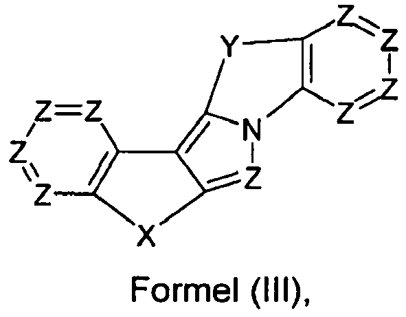
- the present invention relates to an organic electroluminescent device comprising a compound of the formula (I), (II) and (III), or a polymer, oligomer or dendrimer containing one or more compounds of the formula (I), (II) or (III ).
- an electroluminescent device comprising a compound of the formula (I), (II) and (III), or a polymer, oligomer or dendrimer containing one or more compounds of the formula (I), (II) or (III ).
- 0, 1, 2, 3, 4, 5 or 6 groups Z are preferably N, and the remaining groups Z are equal to CR 2 .
- Further preferred are 0, 1 or 2 groups Z per aromatic six-membered ring in a compound of the formula (I), (II) or (III) is N, and the remaining groups Z are equal to CR 2 .
- Y is particularly preferably selected from C (R 2 ) 2 , NR 1 , O and S. Most preferably, Y is C (R 2 ) 2 .
- the preferred embodiments of X and Y combine with each other. Also preferred is the combined appearance of the more preferred or most preferred embodiments of X and Y.
- each occurrence of R 1 is identically or differently selected from an aromatic or heteroaromatic ring system having from 5 to 30 aromatic ring atoms which may be substituted by one or more R 3 radicals.
- the aromatic or heteroaromatic ring system particularly preferably comprises one or more aryl or heteroaryl groups selected from benzene, naphthalene, anthracene, phenanthrene, pyrene, chrysene, benzanthracene, tetracene, pentacene, furan, benzofuran, thiophene, benzothiophene, pyrrole, indole, isoindole, carbazole , Pyridine, quinoline, isoquinoline, pyrazole, imidazole, benzimidazole, pyridazine, pyrimidine, pyrazine, triazole, benzotriazole and triazine, each of which may be substituted
- HetAr 1 represents a heteroaryl group having 1 to 20 C atoms, which may be substituted by one or more R 3 radicals.
- the preferred formulas listed in the table appear in combination with the above-mentioned preferred embodiments of the groups Z, R 1 , R 2 and R 3 .
- the synthesis of the compounds according to the invention can be carried out by organic synthesis methods known to the person skilled in the art, for example Hartwig-Buchwald reaction and Friedel-Crafts alkylation.
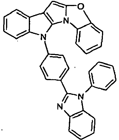
- Scheme 1 shows a process for the synthesis of a compound according to formula (I) according to the invention which has a group NAr as a divalent group X and which has a group CR 2 as a divalent group Y.
- This is based on the shown commercially available pyrrolo-indole compound which is reacted with a Phenylboronklaivat so that a coupling between the pyrrole nitrogen atom and the phenyl group takes place.
- the present in vicinaler position to the pyrrole nitrogen atom carboxylic acid ester is now reduced by addition of an organolithium compound to the tertiary alcohol, and it is a ring closure reaction under acidic conditions performed with the phenyl group.
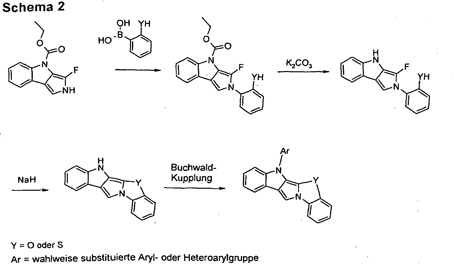
- Scheme 2 shows a process for the synthesis of a compound according to formula (I) according to the invention which has as a divalent group X a group NAr and which as group DY has a group O or S.
- the method differs from that shown in Scheme 1 essentially in that a different ring closure reaction is used to introduce the group Y.
- the starting material used is a pyrroloindole derivative which has a fluorine atom in the vicinal position relative to the pyrrole nitrogen atom.
- a phenyl group is coupled to the pyrrole nitrogen atom which has a group -OH or -SH in the appropriate position.
- the ring closure reaction now takes place between the group -OH or -SH and the fluorine-substituted carbon atom of the pyrrole ring under strongly basic conditions (NaH). In this case, the desired O- or S-bridging is produced.
- Scheme 3 shows a process for the synthesis of a compound according to formula (II) according to the invention.
- the synthetic route is largely analogous to that shown in Scheme 1, with the difference that the starting material used is an isomeric pyrroloindole derivative.
- the compounds according to the invention described above in particular compounds which are substituted by reactive leaving groups, such as bromine, iodine, chlorine, boronic acid or boronic acid esters, can be used as monomers for the production of corresponding oligomers, dendrimers or polymers.
- the oligomerization or polymerization is preferably carried out via the halogen functionality or the boronic acid functionality.
- the invention therefore further provides oligomers, polymers or dendrimers containing one or more compounds of the formula (I), (II) or (III), where the bond (s) to the polymer, oligomer or dendrimer are given at any, in formula (I) , (II) or (III) with R 1 or R 2 substituted positions can be located.
- the compound is part of a side chain of the oligomer or polymer or constituent of the main chain.
- An oligomer in the context of this invention is understood as meaning a compound which is composed of at least three monomer units.
- a polymer is understood as meaning a compound which consists of at least ten monomer units is constructed.
- the polymers, oligomers or dendrimers of the invention may be conjugated, partially conjugated or non-conjugated.
- the oligomers or polymers of the invention may be linear, branched or dendritic.
- the units of the formula (I), (II) or (III) may be linked directly to each other or they may have a bivalent group, for example a substituted or unsubstituted alkylene group, a heteroatom or a bivalent aromatic or heteroaromatic group linked together.
- three or more units of the formula (I), (II) or (III) can have a trivalent or higher valent group, for example via a trivalent or higher valent aromatic or heteroaromatic group, to a branched or dendritic oligomer or Being polymer linked.
- the repeat units of the formula (I), (II) or (III) in oligomers, dendrimers and polymers have the same preferences as described above for compounds of the formula (I), (II) or (III).
- the monomers according to the invention are homopolymerized or copolymerized with further monomers.
- Suitable and preferred comonomers are selected from fluorene (e.g. EP 842208 or WO 00/22026 ), Spirobifluorenes (eg according to EP 707020 . EP 894107 or WO 06/061181 ), Paraphenylenes (eg according to WO 92/18552 ), Carbazoles (eg according to WO 04/070772 or WO 04/113468 ), Thiophenes (eg according to EP 1028136 ), Dihydrophenanthrenes (e.g.
- WO 05/014689 or WO 07/006383 cis and trans indenofluorenes (eg according to WO 04/041901 or WO 04/113412 ), Ketones (eg according to WO 05/040302 ), Phenanthrenes (eg according to WO 05/104264 or WO 07/017066 ) or several of these units.
- the polymers, oligomers and dendrimers usually also contain further units, for example emitting (fluorescent or phosphorescent) units, such as.
- Vinyl triarylamines e.g. WO 07/068325
- phosphorescent metal complexes eg according to WO 06/003000
- charge transport units especially those based on triarylamines.
- the polymers, oligomers and dendrimers according to the invention have advantageous properties, in particular high lifetimes, high efficiencies and good color coordinates.
- the present invention thus also provides a process for the preparation of the polymers, oligomers and dendrimers according to the invention, which is characterized in that it is prepared by polymerization according to SUZUKI; Polymerization according to YAMAMOTO, polymerization according to SILENCE or polymerization according to HARTWIG-BUCHWALD.
- the dendrimers according to the invention can be prepared according to methods known to the person skilled in the art or in analogy thereto. Suitable methods are described in the literature, such as.
- formulations of the compounds according to the invention are required. These formulations may be, for example, solutions, dispersions or miniemulsions.
- the invention therefore further provides a formulation, in particular a solution, dispersion or miniemulsion comprising at least one compound of the formula (I), (II) or (III) or at least one polymer, oligomer or dendrimer comprising at least one unit of the formula (I ), (II) or (III) and at least one solvent, preferably an organic solvent.
- a formulation in particular a solution, dispersion or miniemulsion comprising at least one compound of the formula (I), (II) or (III) or at least one polymer, oligomer or dendrimer comprising at least one unit of the formula (I ), (II) or (III) and at least one solvent, preferably an organic solvent.
- the compounds of the formula (I), (II) or (III) according to the invention are suitable for use in electronic devices, in particular in organic electroluminescent devices (OLEDs). Depending on the substitution, the compounds are used in different functions and / or layers.
- OLEDs organic electroluminescent devices
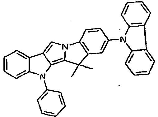
- compounds of the invention which contain electron-deficient groups such as six-membered heteroaryl groups having one or more nitrogen atoms or five-membered heteroaryl groups having two or more heteroatoms are particularly suitable for use as a matrix material for phosphorescent dopants, as an electron transport material or as a hole blocking material.
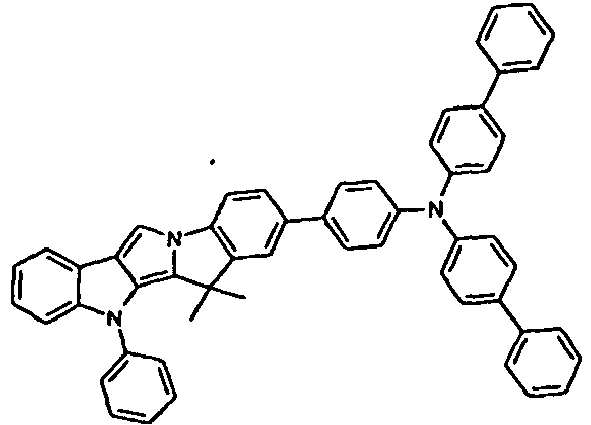
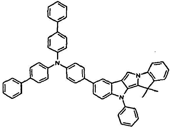
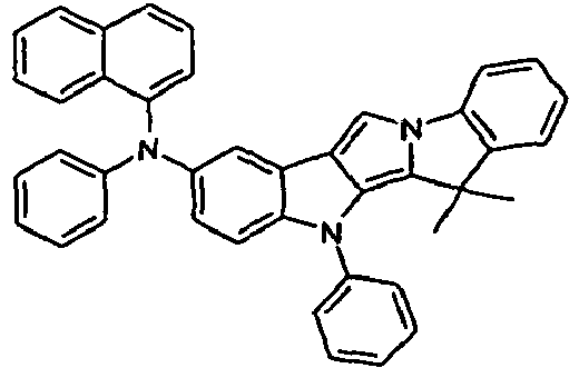
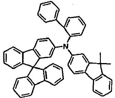
- compounds according to the invention which are substituted with aromatic or heteroaromatic ring systems having 5 to 20 aromatic ring atoms, in particular with aromatic ring systems having 12 to 20 aromatic ring atoms, and / or with one or more arylamino groups, especially for use as hole transport materials or for use as fluorescent Dopants suitable.
- the compounds according to the invention are preferably used as matrix material in an emitting layer, as hole transport material in a hole transport layer or as electron transport material in an electron transport layer. With further preference the compounds according to the invention are used in a hole injection layer. However, they can also be used in other layers and / or functions, for example as fluorescent dopants in an emitting layer or as hole or electron blocking materials.
- the electronic devices are preferably selected from the group consisting of organic integrated circuits (O-ICs), organic field-effect transistors (O-FETs), organic thin-film transistors (O-TFTs), organic light-emitting transistors (O-LETs), organic solar cells (O-SCs), organic optical detectors, organic photoreceptors, organic field quench devices (O-FQDs), light-emitting electrochemical cells (LECs), organic laser diodes (O-lasers) and more preferably selected from organic electroluminescent devices (OLEDs ).
- O-ICs organic integrated circuits
- O-FETs organic field-effect transistors
- OF-TFTs organic thin-film transistors
- O-LETs organic light-emitting transistors
- O-SCs organic solar cells
- organic optical detectors organic photoreceptors
- O-FQDs organic field quench devices
- LECs organic laser diodes
- O-lasers organic laser diodes
- Yet another object of the invention are electronic devices containing at least one compound of formula (I), (II) or (III).
- the electronic devices are preferably selected from the above-mentioned devices.
- organic electroluminescent devices comprising the anode, cathode and at least one emitting layer in that at least one organic layer, which may be an emitting layer, an electron transport layer or another layer, contains at least one compound according to formula (I), (II) or (III).
- the organic electroluminescent device may contain further layers. These are selected, for example, from one or more hole injection layers, hole transport layers, hole blocking layers, electron transport layers, electron injection layers, electron blocking layers, exciton blocking layers, charge generation layers (IDMC 2003, Taiwan, Session 21 OLED (5), T. Matsumoto, T. Nakada, J. Endo. K. Mori, N. Kawamura, A. Yokoi, J. Kido, Multiphoton Organic EL Device Having Charge Generation Layer) , Outcoupling layers and / or organic or inorganic p / n junctions.
- each of these layers must be present and the choice of layers always depends on the compounds used and in particular also on the fact that it is a fluorescent or phosphorescent electroluminescent device.
- the preferred compounds used in the respective layers and functions will be explicitly disclosed in later sections.
- the compound of the formula (I), (II) or (III) is used in an electronic device containing one or more phosphorescent dopants.
- the compound can be used in different layers, preferably in an electron transport layer, a hole transport layer, a hole injection layer or in the emitting layer.
- the compound of the formula (I), (II) or (III) can also be used according to the invention in an electronic device containing one or more fluorescent dopants and no phosphorescent dopants.
- Particularly suitable phosphorescent dopants are compounds which, with suitable excitation, emit light, preferably In the visible range, emit and also contain at least one atom of atomic number greater than 20, preferably greater than 38 and less than 84, more preferably greater than 56 and less than 80 included.
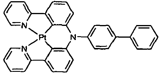
- phosphorescent dopants compounds containing copper, molybdenum, tungsten, rhenium, ruthenium, osmium, rhodium, iridium, palladium, platinum, silver, gold or europium are preferably used, in particular compounds containing iridium, platinum or copper.
- luminescent iridium, platinum or copper complexes are regarded as phosphorescent compounds.
- Examples of the above-described phosphorescent dopants can be found in the applications WO 2000/70655 . WO 2001/41512 . WO 2002/02714 . WO 2002/15645 . EP 1191613 . EP 1191612 . EP 1191614 . WO 2005/033244 . WO 2005/019373 and US 2005/0258742 be removed.
- all phosphorescent complexes which are used according to the prior art for phosphorescent OLEDs and as are known to the person skilled in the art of organic electroluminescent devices are suitable. The skilled person can also use other phosphorescent complexes in combination with the compounds according to the invention in organic electroluminescent devices without inventive step.
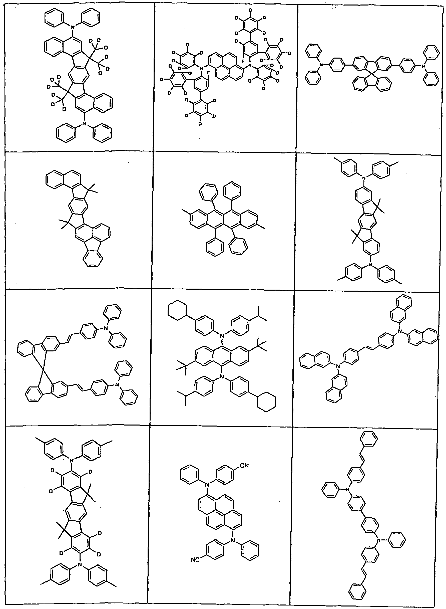
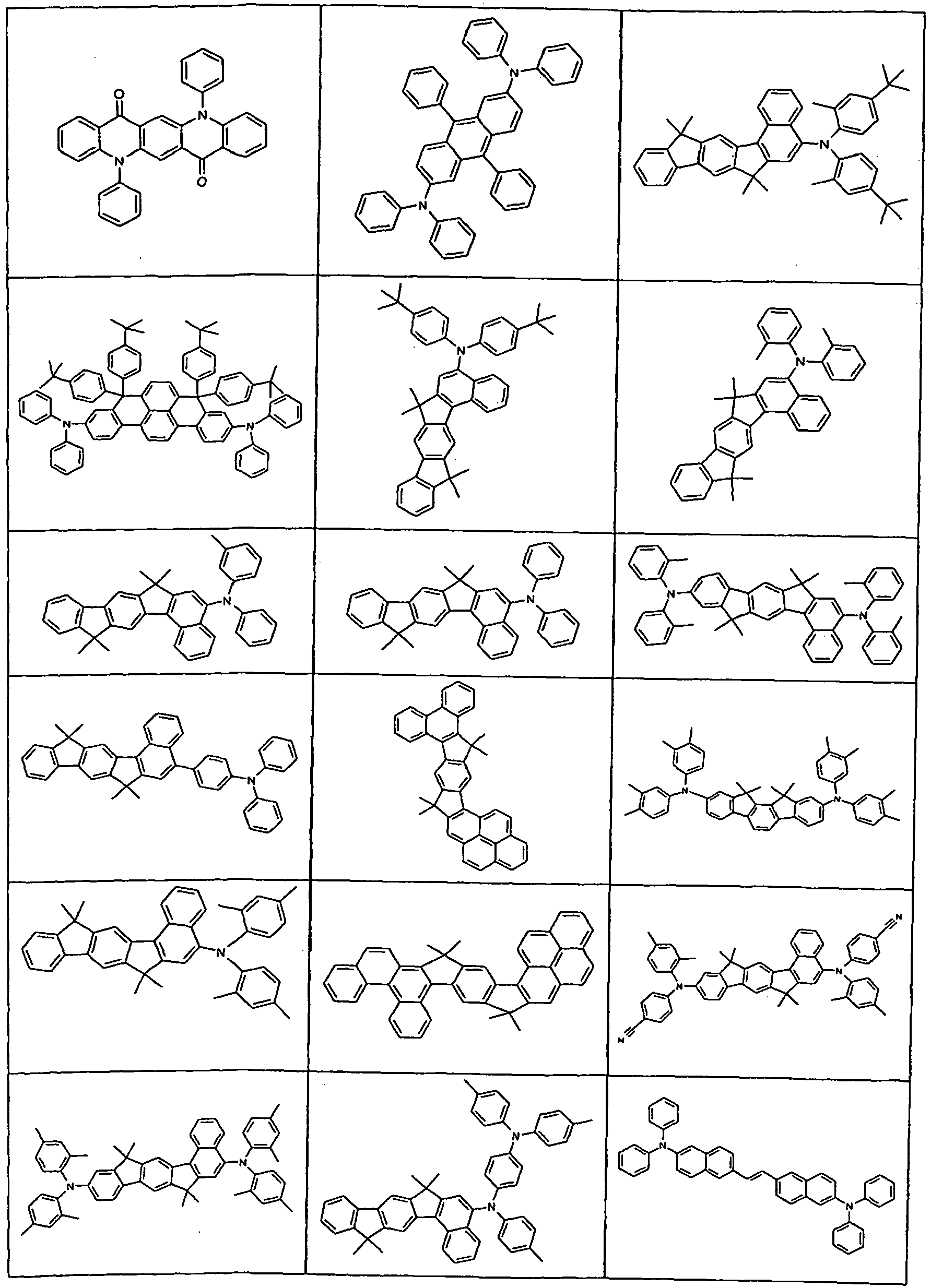
- Suitable phosphorescent dopants can be found in the table which follows in a later section.
- the compounds of the formula (I), (II) or (III) are used as matrix material in combination with one or more dopants, preferably phosphorescent dopants.
- the compounds are particularly suitable for use as a matrix material if they contain one or more electron-deficient groups, such as six-membered heteroaryl groups containing one or more nitrogen atoms or five-membered heteroaryl groups containing two or more nitrogen atoms.
- a dopant in a system comprising a matrix material and a dopant, is understood to mean the component whose proportion in the mixture is the smaller.
- a matrix material in a system containing a matrix material and a dopant is understood to mean the component whose proportion in the mixture is the larger.
- the proportion of the matrix material in the emitting layer is in this case between 50.0 and 99.9% by volume, preferably between 80.0 and 99.5% by volume and particularly preferred for fluorescent emitting layers between 92.0 and 99.5% by volume and for phosphorescent emitting layers between 85.0 and 97.0 vol.%. Accordingly, the proportion of the dopant is between 0.1 and 50.0% by volume, preferably between 0.5 and 20.0% by volume and particularly preferred for fluorescent emitting layers between 0.5 and 8.0% by volume and for phosphorescent emitting layers between 3.0 and 15.0% by volume. -%.
- An emitting layer of an organic electroluminescent device may also contain systems comprising a plurality of matrix materials (mixed-matrix systems) and / or multiple dopants.
- the dopants are generally those materials whose proportion in the system is smaller and the matrix materials are those materials whose proportion in the system is larger. In individual cases, however, the proportion of a single matrix material in the system may be smaller than the proportion of a single dopant.
- the compounds according to formula (I), (II) or (III) are used as a component of mixed-matrix systems.
- the mixed-matrix systems preferably comprise two or three different matrix materials, more preferably two different matrix materials.
- one of the two materials preferably constitutes a material with hole-transporting properties and the other material a material with electron-transporting properties.
- the two different matrix materials can be present in a ratio of 1:50 to 1: 1, preferably 1:20 to 1: 1, more preferably 1:10 to 1: 1 and all more preferably 1: 6 to 1: 1. Preference is given to using mixed-matrix systems in phosphorescent organic electroluminescent devices.
- the mixed-matrix systems may comprise one or more dopants.
- the dopant compound or the dopant compounds together according to the invention have a proportion of 0.1 to 50.0% by volume of the total mixture and preferably a proportion of 0.5 to 20.0% by volume of the total mixture. Accordingly, the matrix components together have a proportion of 50.0 to 99.9% by volume of the total mixture and preferably a proportion of 80.0 to 99.5% by volume of the total mixture.
- Particularly suitable matrix materials which can be used in combination with the compounds according to the invention as matrix components of a mixed-matrix system are aromatic ketones, aromatic phosphine oxides or aromatic sulfoxides or sulfones, eg. B. according to WO 2004/013080 . WO 2004/093207 . WO 2006/005627 or WO 2010/006680 , Triarylamines, carbazole derivatives, e.g. B. CBP (N, N-Biscarbazolylbiphenyl) or in WO 2005/039246 . US 2005/0069729 . JP 2004/288381 .
- EP 1205527 or WO 2008/086851 disclosed carbazole derivatives, indolocarbazole derivatives, e.g. B. according to WO 2007/063754 or WO 2008/056746 , Azacarbazolderivate, z. B. according to EP 1617710 . EP 1617711 . EP 1731584 . JP 2005/347160 , bipolar matrix materials, e.g. B. according to WO 2007/137725 , Silane, z. B. according to WO 2005/111172 , Azaborole or Boronester, z. B. according to WO 2006/117052 , Triazine derivatives, e.g. B. according to WO 2010/015306 .
- Zinc complexes e.g. B. according to EP 652273 or WO 2009/062578 , Diazasilol- or tetraazasilol derivatives, z. B. according to WO 2010/054729 , Diazaphosphole derivatives, e.g. B. according to WO 2010/054730 , Indenocarbazole derivatives, e.g. B. according to WO 2010/136109 and WO 2011/000455 , or bridged carbazoles, e.g. B according to WO 2011/088877 and WO 2011/128017 ,
- Preferred phosphorescent dopants for use in mixed-matrix systems containing the compounds of the invention are the phosphorescent dopants listed in a table below.
- the compounds of the formula (I), (II) or (III) are used as hole transport material.
- the compounds are then preferably used in a hole transport layer and / or in a hole injection layer.
- a hole injection layer in the sense of this invention is a layer which is directly adjacent to the anode.
- a hole transport layer in the sense of this invention is a layer that lies between the hole injection layer and the emission layer.
- the compounds are particularly suitable for use as a hole transport material when substituted with one or more aromatic ring systems having from 12 to 20 aromatic ring atoms and / or having one or more arylamino groups.
- the compound of the formula (I), (II) or (III) when used as a hole transport material in a hole transport layer, the compound may be used as a pure material, i. are used in a proportion of 100% in the hole transport layer, or it can be used in combination with other compounds, in particular p-dopants, in the hole transport layer.
- the compounds of the formula (I), (II) or (III) are used as fluorescent dopants in an emitting layer.
- the compounds are particularly suitable for use as fluorescent dopants when substituted with one or more aromatic systems, preferably aromatic systems containing from 12 to 20 aromatic ring atoms.
- the compounds of the invention are preferably used as green or blue emitters.
- the proportion of the compound according to formula (I), (II) or (III) as dopant in the mixture of the emitting layer in this case is between 0.1 and 50.0% by volume, preferably between 0.5 and 20.0% by volume, particularly preferred between 0.5 and 8.0 vol.%.
- the proportion is accordingly of the matrix material between 50.0 and 99.9% by volume, preferably between 80.0 and 99.5% by volume, particularly preferably between 92.0 and 99.5% by volume.
- Preferred matrix materials for use in combination with the compounds of the invention as fluorescent dopants are listed in one of the following sections. They correspond to the preferred matrix materials for fluorescent dopants.
- the compounds are used as electron transport materials in an electron transport layer of an organic electroluminescent device.
- the compounds of the invention one or more electron-poor groups such.
- the organic electroluminescent device may also include a plurality of emitting layers.
- these emission layers particularly preferably have a total of a plurality of emission maxima between 380 nm and 750 nm, resulting in a total white emission, ie different emitting compounds which can fluoresce or phosphoresce are used in the emitting layers and the blue or yellow or orange or emit red light, with the different colors together giving white light in this embodiment of the invention.
- three-layer systems ie systems having three emitting layers, one or more of these layers containing a compound of the formula (I), (II) or (III) and the three layers exhibiting blue, green and orange or red emission (for the basic structure see eg WO 2005/011013 ).
- white emission emitters which have broadband emission bands and thereby show white emission.
- the compounds according to the invention in such systems can also be present in a hole transport layer or electron transport layer or in another layer.
- Particularly suitable phosphorescent dopants are the compounds listed in the following table.
- Preferred fluorescent dopants are selected from the class of monostyrylamines, distyrylamines, tristyrylamines, tetrastyrylamines, styrylphosphines, styryl ethers and arylamines.
- a monostyrylamine is meant a compound containing a substituted or unsubstituted styryl group and at least one, preferably aromatic, amine.
- a distyrylamine is understood as meaning a compound which contains two substituted or unsubstituted styryl groups and at least one, preferably aromatic, amine.
- a tristyrylamine is understood as meaning a compound which contains three substituted or unsubstituted styryl groups and at least one, preferably aromatic, amine.
- a tetrastyrylamine is meant a compound containing four substituted or unsubstituted styryl groups and at least one, preferably aromatic, amine.
- the styryl groups are particularly preferred stilbenes, which may also be further substituted.
- Corresponding styrylphosphines and styryl ethers are defined in analogy to the amines.
- An arylamine or an aromatic amine in the context of this invention is understood as meaning a compound which contains three substituted or unsubstituted aromatic or heteroaromatic ring systems bonded directly to the nitrogen. At least one of these aromatic or heteroaromatic ring systems is preferably a fused ring system, more preferably at least 14 aromatic ring atoms. Preferred examples of these are aromatic anthraceneamines, aromatic anthracenediamines, aromatic pyrenamines, aromatic pyrenediamines, aromatic chrysenamines or aromatic chrysenediamines.
- aromatic anthracene amine is meant a compound in which a diarylamino group is bonded directly to an anthracene group, preferably in the 9-position.
- Aromatic pyrenamines, pyrenediamines, chrysenamines and chrysenediamines are defined analogously thereto, the diarylamino groups on the pyrene preferably being bonded in the 1-position or in the 1,6-position.
- fluorescent dopants are selected from indenofluorenamines or diamines, for example according to WO 2006/122630 , Benzoindenofluorenaminen or diamines, for example according to WO 2008/006449 , and Dibenzoindenoflüorenaminen or diamines, for example according to WO 2007/140847 ,
- fluorescent dopants from the class of styrylamines are substituted or unsubstituted tristilbenamines or the fluorescent dopants which are disclosed in US Pat WO 2006/000388 .
- WO 2006/000389 WO 2007/065549
- WO 2007/115610 are described.
- Further preferred are those in DE 102008035413 disclosed condensed hydrocarbons.
- the compounds of the formula (I), (II) or (III) can be used as fluorescent dopants.
- Suitable fluorescent dopants are furthermore the structures depicted in the following table, as well as those in US Pat JP 2006/001973 . WO 2004/047499 . WO 2006/098080 . WO 2007/065678 . US 2005/0260442 and WO 2004/092111 disclosed derivatives of these structures.
- Suitable matrix materials are materials of different substance classes.
- Preferred matrix materials are selected from the classes of oligoarylenes (eg. 2,2 ', 7,7'-tetraphenyl (spirobifluorene according to EP 676461 or dinaphthylanthracene), in particular the oligoarylenes containing condensed aromatic groups, of the oligoarylenevinylenes (for example DPVBi or spiro-DPVBi according to US Pat EP 676461 ), the polypodal metal complexes (eg according to.
- WO 2004/081017 the hole-conducting compounds (eg according to WO 2004/058911 ), the electron-conducting compounds, in particular ketones, phosphine oxides, sulfoxides, etc. (for example according to US Pat WO 2005/084081 and WO 2005/084082 ), the atropisomers (eg according to WO 2006/048268 ), the boronic acid derivatives (eg according to WO 2006/117052 ) or the benzanthracenes (eg according to WO 2008/145239 ).
- Further suitable matrix materials are preferably the compounds according to the invention.
- Particularly preferred matrix materials are selected from the classes of oligoarylenes containing naphthalene, anthracene, benzanthracene and / or pyrene or atropisomers of these compounds, the oligoarylenevinylenes, the ketones, the phosphine oxides and the sulfoxides.
- Very particularly preferred matrix materials are selected from the classes of oligoarylenes containing anthracene, benzanthracene, benzphenanthrene and / or pyrene or atropisomers of these compounds.
- An oligoaryfen in the sense of this invention is to be understood as meaning a compound in which at least three aryl or arylene groups are bonded to one another.
- Suitable matrix materials are, for example, the materials depicted in the following table, as well as derivatives of these materials, as described in US Pat WO 2004/018587 . WO 2008/006449 . US 5935721 . US 2005/0181232 . JP 2000/273056 . EP 681019 . US 2004/0247937 and US 2005/0211958 be revealed.
- Suitable charge transport materials as used in Lochinjetechnische transport layer or in the electron transport layer of the organic electroluminescent device according to the invention can be used, in addition to the compounds of the invention, for example, those in Y. Shirota et al., Chem. Rev. 2007, 107 (4), 953-1010 disclosed compounds or other materials, as used in the prior art in these layers.
- the cathode of the organic electroluminescent device are low work function metals, metal alloys or multilayer structures of various metals, such as alkaline earth metals, alkali metals, main group metals or lanthanides (eg Ca, Ba, Mg, Al, In, Mg, Yb, Sm, Etc.). Also suitable are alloys of an alkali or alkaline earth metal and silver, for example an alloy of magnesium and silver. In multilayer structures, it is also possible, in addition to the metals mentioned, to use further metals which have a relatively high work function, such as, for example, As Ag or Al, which then usually combinations of metals, such as Ca / Ag, Ba / Ag or Mg / Ag are used.
- a metallic cathode and the organic semiconductor may also be preferred to introduce between a metallic cathode and the organic semiconductor a thin intermediate layer of a material with a high dielectric constant.
- Suitable examples of these are alkali metal or alkaline earth metal fluorides, but also the corresponding oxides or carbonates (eg LiF, Li 2 O, BaF 2 , MgO, NaF, CsF, Cs 2 CO 3 , etc.).
- lithium quinolinate (LiQ) can be used for this purpose.
- the layer thickness of this layer is preferably between 0.5 and 5 nm.
- the anode high workfunction materials are preferred.
- the anode has a work function greater than 4.5 eV. Vacuum up.
- metals with a high redox potential such as Ag, Pt or Au, are suitable for this purpose.
- It may on the other hand (Al / Ni / NiO x, Al / PtO x z. B.) be preferred MetalliMetalloxid electrodes.
- at least one of the electrodes must be transparent or partially transparent to allow either the irradiation of the organic material (organic solar cell) or the outcoupling of light (OLED, O-LASER).
- Preferred anode materials here are conductive mixed metal oxides. Particularly preferred are indium tin oxide (ITO) or indium zinc oxide (IZO). Preference is still given conductive, doped organic materials, in particular conductive doped polymers.
- the device is structured accordingly (depending on the application), contacted and finally sealed, since the life of the devices according to the invention is shortened in the presence of water and / or air.
- the organic electroluminescent device according to the invention is characterized in that one or more layers are coated with a sublimation method.
- the materials are vapor-deposited in Valcuum Sublimationsanfagen at an initial pressure less than 10 -5 mbar, preferably less than 10 -6 mbar. However, it is also possible that the initial pressure is even lower, for example less than 10 -7 mbar.
- an organic electroluminescent device characterized in that one or more layers are coated with the OVPD (Organic Vapor Phase Deposition) method or with the aid of a carrier gas sublimation.
- the materials are applied at a pressure between 10 -5 mbar and 1 bar.
- OVJP Organic Vapor Jet Printing
- the materials are applied directly through a nozzle and thus structured (eg. MS Arnold et al., Appl. Phys. Lett. 2008, 92, 053301 ).
- an organic electroluminescent device characterized in that one or more layers of solution, such. B. by spin coating, or with any printing process, such.
- any printing process such.
- screen printing flexographic printing, Nozzle Printing or offset printing, but particularly preferably LITI (Light Induced Thermal Imaging, thermal transfer printing) or ink-jet printing (ink jet printing) are produced.
- LITI Light Induced Thermal Imaging, thermal transfer printing
- ink-jet printing ink jet printing
- soluble compounds according to formula (I), (II) or (III) are necessary. High solubility can be achieved by suitable substitution of the compounds.
- one or more layers of solution and one or more layers are applied by a sublimation method.
- organic electroluminescent devices comprising one or more compounds according to the invention can be used in displays, as light sources in illumination applications and as light sources in medical and / or cosmetic applications (for example light therapy).
- the compounds of the invention are characterized by a high oxidation stability in solution, which is advantageous in the purification and handling of the compounds and their use in electronic devices.
- the compounds according to the invention are temperature-stable and can thus be sublimated largely without decomposition.
- the purification of the compounds is thereby facilitated, and the compounds can be obtained in higher purity, which has a positive effect on the performance data of the electronic devices containing the materials. In particular, devices with longer operational lifetimes can be produced thereby.
- inventive OLEDs and OLEDs according to the prior art is carried out according to a general method according to WO 2004/058911 , which is adapted to the conditions described here (layer thickness variation, materials).
- the OLEDs have in principle the following layer structure: Substrate / hole transport layer (HTL) / optional interlayer (IL) / electron blocker layer (EBL) / emission layer (EML) / optional hole blocking layer (HBL) / electron transport layer (ETL) / optional electron injection layer (EIL) and finally a cathode ,
- the cathode is formed by a 100 nm thick aluminum layer.
- Table 1 The exact structure of the OLEDs is shown in Table 1.
- the materials needed to make the OLEDs are shown in Table 3.
- the emission layer always consists of at least one matrix material (host material, host material) and an emitting dopant (dopant, emitter), which is admixed to the matrix material or the matrix materials by co-evaporation in a certain volume fraction.
- the OLEDs are characterized by default.
- the electroluminescence spectra are determined at a luminance of 1000 cd / m 2 and from this the CIE 1931 x and y color coordinates are calculated.
- the indication U1000 in Table 2 indicates the voltage required for a luminance of 1000 cd / m 2 .
- SE1000 and LE1000 indicate the power efficiency achieved at 1000 cd / m 2 .
- EQE1000 refers to external quantum efficiency at an operating luminance of 1000 cd / m 2 .
Landscapes
- Chemical & Material Sciences (AREA)
- Organic Chemistry (AREA)
- Engineering & Computer Science (AREA)
- Materials Engineering (AREA)
- Physics & Mathematics (AREA)
- Spectroscopy & Molecular Physics (AREA)
- Life Sciences & Earth Sciences (AREA)
- Health & Medical Sciences (AREA)
- Biochemistry (AREA)
- General Health & Medical Sciences (AREA)
- Molecular Biology (AREA)
- Inorganic Chemistry (AREA)
- Electroluminescent Light Sources (AREA)
- Nitrogen Condensed Heterocyclic Rings (AREA)
- Nitrogen And Oxygen Or Sulfur-Condensed Heterocyclic Ring Systems (AREA)
- Low-Molecular Organic Synthesis Reactions Using Catalysts (AREA)
- Photovoltaic Devices (AREA)
Description
- Die vorliegende Erfindung betrifft eine organische Elektrolumineszenzvorrichtung, enthaltend eine Verbindung der Formel (I), (II) und (III), oder ein Polymer, Oligomer oder Dendrimer, enthaltend eine oder mehrere Verbindungen der Formel (I), (II) oder (III). Weiterhin betrifft die Erfindung ein Verfahren zur Herstellung einer Verbindung der Formel (I), (II) oder (III) sowie eine Formulierung enthaltend eine oder mehrere Verbindungen der Formel (I), (II) oder (III).
- Organische Halbleitermaterialien wie die erfindungsgemäßen Verbindungen werden für eine Reihe verschiedenartiger Anwendungen in elektronischen Vorrichtungen entwickelt. Der Aufbau organischer Elektrolumineszenzvorrichtungen (OLEDs), in denen die erfindungsgemäßen Verbindungen als funktionelle Materialien eingesetzt werden können, ist beispielsweise in
US 4539507 ,US 5151629 ,EP 0676461 undWO 1998/27136 - Betreffend die Leistungsdaten der organischen Elektrolumineszenzvorrichtungen sind, insbesondere in Hinblick auf eine breite kommerzielle Verwendung, noch weitere Verbesserungen erforderlich. Von besonderer Bedeutung sind in diesem Zusammenhang die Lebensdauer, die Effizienz und die Betriebsspannung der organischen Elektrolumineszenz-vorrichtungen sowie die realisierten Farbwerte. Insbesondere bei blau emittierenden Elektrolumineszenzvorrichtungen besteht Verbesserungspotential bezüglich der Lebensdauer der Vorrichtungen.
- Zudem ist es wünschenswert, dass die Verbindungen zur Verwendung als organische Halbleitermaterialien eine hohe thermische Stabilität und eine hohe Glasübergangstemperatur aufweisen und sich unzersetzt sublimieren lassen.
- Es besteht in diesem Zusammenhang unter anderem Bedarf an an alternativen Matrixmaterialien zur Verwendung in elektronischen Vorrichtungen. Insbesondere besteht Bedarf an Matrixmaterialien für phosphoreszierende Emitter, die gleichzeitig zu guter Effizienz, hoher Lebensdauer und geringer Betriebsspannung führen. Gerade die Eigenschaften der Matrixmaterialien sind häufig limitierend für die Lebensdauer und die Effizienz der organischen Elektrolumineszenzvorrichtung.
- Gemäß dem Stand der Technik werden häufig Carbazolderivate, z. B. Bis(carbazolyl)biphenyl, als Matrixmaterialien verwendet. Hier besteht noch Verbesserungspotential insbesondere in Bezug auf die Lebensdauer und die Glasübergangstemperatur der Materialien.
- Weiterhin werden gemäß dem Stand der Technik Ketonverbindungen, z. B. wie in
WO 2005/084081 ,WO 2004/093207 undWO 2004/013080 beschrieben, als Matrixmaterialien in OLEDs eingesetzt. Nochmals weiterhin werden gemäß dem Stand der Technik Triazinverbindungen als Matrixmaterialien verwendet, z. B. wie inWO 2010/015306 ,WO 2007/063754 oderWO 2008/056746 offenbart. Es besteht jedoch weiterhin Bedarf an alternativen Verbindungen mit anderer chemischer Struktur, insbesondere solchen, die eine Verbesserung betreffend Lebensdauer, Effizienz und Betriebsspannung bewirken. - Von besonderem Interesse ist weiterhin die Bereitstellung von alternativen Materialien als Matrixkomponenten von Mixed-Matrix-Systemen. Unter einem Mixed-Matrix-System wird im Sinne dieser Anmeldung ein System verstanden, in dem zwei oder mehr verschiedene Matrixverbindungen zusammen mit einer (alternativ auch mehreren) Dotandverbindungen gemischt als emittierende Schicht verwendet werden. Diese Systeme sind insbesondere von Interesse bei phosphoreszierenden organischen Elektrolumineszenzvorrichtungen. Für detailliertere Informationen wird auf die Anmeldung
WO 2010/108579 verwiesen. Als im Stand der Technik bekannte Verbindungen als Matrixkomponenten in Mixed-Matrix-Systemen sind unter anderem CBP (Biscarbazolylbiphenyl) und TCTA (Triscarbazolyltriphenylamin) zu nennen. Es besteht jedoch weiterhin Bedarf an alternativen Verbindungen zur Verwendung als Matrixkomponenten in Mixed-Matrix-Systemen. Insbesondere besteht Bedarf an Verbindungen, welche eine Verbesserung der Betriebsspannung und Lebensdauer der elektronischen Vorrichtungen bewirken. - Weiterhin ist die Bereitstellung neuer Elektronentransportmaterialien wünschenswert, da gerade auch die Eigenschaften des Elektronentransportmaterials einen wesentlichen Einfluss auf die oben genannten Eigenschaften der organischen Elektrolumineszenzvorrichtung ausüben. Insbesondere besteht Bedarf an Elektronentransportmaterialien, welche gleichzeitig zu guter Effizienz, hoher Lebensdauer und geringer Betriebsspannung führen.
- In den Anmeldungen
WO 2010/136109 undWO 2011/000455 werden Indenocarbazol- und Indolocarbazolderivate mit unterschiedlicher Verknüpfungsgeometrie der Inden- bzw. Indol- und der Carbazoleinheit offenbart. Die Verbindungen eignen sich sehr gut zur Verwendung als Funktionsmaterialien in organischen Elektrolumineszenzvorrichtungen, insbesondere als Matrixmaterialien für phosphoreszierende Emitter sowie als Elektronentransportmaterialien. Die Synthese von Indenderivaten ist weiterhin bekannt (z. B. W.v. Miller und Ruhde, diese Berichte XXII, 1830). Es besteht jedoch weiterhin Bedarf an alternativen Verbindungen, insbesondere solchen, mit denen eine Senkung der Betriebsspannung, eine Erhöhung der Leistungseffizienz sowie eine Erhöhung der Lebensdauer erreicht werden kann. - In der Anmeldung
JP 2006/066580 - In der Anmeldungen
JP 2007/088016 JP 2000/268962 - In der noch nicht offengelegten Anmeldung
DE 102010033548.7 werden organische Halbleitermaterialien, welche mehrere miteinander kondensierte heteroaromatische Fünfringe aufweisen, offenbart. Die Materialien werden gemäß der genannten Anmeldung bevorzugt in OLEDs verwendet. - Die vorliegende Erfindung betrifft eine organische Elektrolumineszenzvorrichtung, enthaltend eine Verbindung der Formel (I), (II) und (III), oder ein Polymer, Oligomer oder Dendrimer, enthaltend eine oder mehrere Verbindungen der Formel (I), (II) oder (III). Die vorteilhaften Eigenschaften von so einer Elektrolumineszenzvorrichtung werden in einem der folgenden Abschnitte sowie in den experimentellen Beispielen im Detail dargelegt.
-
- Z
- ist bei jedem Auftreten gleich oder verschieden ausgewählt aus CR2 und N;
- X, Y
- sind bei jedem Auftreten gleich oder verschieden eine divalente Gruppe, ausgewählt aus BR2, C(R2)2, C=O, C=NR2, C=S, Si(R2)2, NR1, PR2, P(=O)R2, O, S, S=O und S(=O)2;
- R1
- ist bei jedem Auftreten gleich oder verschieden ein aromatisches oder heteroaromatisches Ringsystem mit 5 bis 60 aromatischen Ringatomen, welches mit einem oder mehreren Resten R3 substituiert sein kann und welches mit einem Substituenten R2 am Grundgerüst oder einem Atom des Grundgerüsts verknüpft sein kann;
- R2
- ist bei jedem Auftreten gleich oder verschieden H, D, F, Cl, Br, I, B(OR3)2, CHO, C(=O)R3, CR3=C(R3)2, CN, C(=O)OR3, C(=O)N(R3)2, Si(R3)3, N(R3)2, N(Ar1)2, NO2, P(=O)(R3)2, OSO2R3, OR3, S(=O)R3, S(=O)2R3, eine geradkettige Alkyl-, Alkoxy- oder Thioalkylgruppe mit 1 bis 20 C-Atomen oder eine verzweigte oder cyclische Alkyl-, Alkoxy- oder Thioalkylgruppe mit 3 bis 20 C-Atomen oder eine Alkenyl- oder Alkinylgruppe mit 2 bis 20 C-Atomen, wobei die oben genannten Gruppen jeweils mit einem oder mehreren Resten R3 substituiert sein können und wobei eine oder mehrere benachbarte oder nicht benachbarte CH2-Gruppen in den oben genannten Gruppen durch -R3C=CR3-, -C≡C-, Si(R3)2, Ge(R3)2, Sn(R3)2, C=O, C=S, C=Se, C=NR3, -C(=O)O-, -C(=O)NR3-, NR3, P(=O)(R3), -O-, -S-, SO oder SO2 ersetzt sein können und wobei ein oder mehrere H-Atome in den oben genannten Gruppen durch D, F, Cl, Br, I, CN oder NO2 ersetzt sein können, oder ein aromatisches oder heteroaromatisches Ringsystem mit 5 bis 60 aromatischen Ringatomen, das jeweils durch einen oder mehrere Reste R3 substituiert sein kann, oder eine Aryloxy- oder Heteroaryloxygruppe mit 5 bis 60 aromatischen Ringatomen, die durch einen oder mehrere Reste R3 substituiert sein kann, wobei zwei oder mehr Reste R2 miteinander verknüpft sein können und einen Ring oder ein Ringsystem bilden können;
- R3
- ist bei jedem Auftreten gleich oder verschieden H, D, F, Cl, Br, I, B(OR4)2, CHO, C(=O)R4, CR4=C(R4)2, CN, C(=O)OR4, C(=O)N(R4)2, Si(R4)3, N(R4)2, NO2, P(=O)(R4)2, OSO2R4, OR4, S(=O)R4, S(=O)2R4, eine geradkettige Alkyl-, Alkoxy- oder Thioalkylgruppe mit 1 bis 20 C-Atomen oder eine verzweigte oder cyclische Alkyl-, Alkoxy- oder Thioalkylgruppe mit 3 bis 20 C-Atomen oder eine Alkenyl- oder Alkinylgruppe mit 2 bis 20 C-Atomen, wobei die oben genannten Gruppen jeweils mit einem oder mehreren Resten R4 substituiert sein können und wobei eine oder mehrere benachbarte oder nicht benachbarte CH2-Gruppen in den oben genannten Gruppen durch -R4C=CR4-, -C=C-, Si(R4)2, Ge(R4)2, Sn(R4)2, C=O, C=S, C=Se, C=NR4, -C(=O)O-, -C(=O)NR4- , NR4, P(=O)(R4), -O-, -S-, SO oder SO2 ersetzt sein können und wobei ein oder mehrere H-Atome in den oben genannten Gruppen durch D, F, Cl, Br, I, CN oder NO2 ersetzt sein können, oder ein aromatisches oder heteroaromatisches Ringsystem mit 5 bis 60 aromatischen Ringatomen, das jeweils durch einen oder mehrere Reste R4 substituiert sein kann, oder eine Aryloxy- oder Heteroaryloxygruppe mit 5 bis 60 aromatischen Ringatomen, die durch einen oder mehrere Reste R4 substituiert sein kann, wobei zwei oder mehr Reste R3 miteinander verknüpft sein können und einen Ring oder ein Ringsystem bilden können;
- R4
- ist gleich oder verschieden bei jedem Auftreten H, D, F oder ein aliphatischer, aromatischer und/oder heteroaromatischer organischer Rest mit 1 bis 20 C-Atomen, in dem auch ein oder mehrere H-Atome durch D oder F ersetzt sein können; dabei können zwei oder mehr Substituenten R4 auch miteinander verknüpft sein und einen Ring oder ein Ringsystem bilden;
- Ar1
- ist bei jedem Auftreten gleich oder verschieden ein aromatisches oder heteroaromatisches Ringsystem mit 5 bis 30 aromatischen Ringatomen, das mit einem oder mehreren Resten R3 substituiert sein kann;
- Bevorzugt sind in den erfindungsgemäßen Verbindungen 0, 1, 2, 3, 4, 5 oder 6 Gruppen Z gleich N, und die restlichen Gruppen Z sind gleich CR2. Weiterhin bevorzugt sind 0, 1 oder 2 Gruppen Z pro aromatischem Sechsring in einer Verbindung der Formel (I), (II) oder (III) gleich N, und die restlichen Gruppen Z sind gleich CR2.
- Gemäß einer bevorzugten Ausführungsform der Erfindung ist X ausgewählt aus BR2, C=O, NR1, PR2, P(=O)R2, O, S, S=O und S(=O)2. Besonders bevorzugt ist X ausgewählt aus C=O, NR1, O, S, S=O und S(=O)2. Ganz besonders bevorzugt ist X gleich NR1.
- Weiterhin ist gemäß einer bevorzugten Ausführungsform der Erfindung Y ausgewählt aus C(R2)2, C=O, NR1, PR2, P(=O)R2, O, S und S(=O)2. Besonders bevorzugt ist Y ausgewählt aus C(R2)2, NR1, O und S. Ganz besonders bevorzugt ist Y gleich C(R2)2.
- In einer besonders bevorzugten Ausführungsform der Erfindung treten die bevorzugten Ausführungsformen von X und Y kombiniert miteinander auf. Ebenfalls bevorzugt ist das kombinierte Auftreten der besonders bevorzugten oder der ganz besonders bevorzugten Ausführungsformen von X und Y.
- In einer bevorzugten Ausführungsform der Erfindung ist R1 bei jedem Auftreten gleich oder verschieden ausgewählt aus einem aromatischen oder heteroaromatischen Ringsystem mit 5 bis 30 aromatischen Ringatomen, welches mit einem oder mehreren Resten R3 substituiert sein kann. Besonders bevorzugt umfasst das aromatische oder heteroaromatische Ringsystem eine oder mehrere Aryl- oder Heteroarylgruppen ausgewählt aus Benzol, Naphthalin, Anthracen, Phenanthren, Pyren, Chrysen, Benzanthracen, Tetracen, Pentacen, Furan, Benzofuran, Thiophen, Benzothiophen, Pyrrol, Indol, Isoindol, Carbazol, Pyridin, Chinolin, Isochinolin, Pyrazol, Imidazol, Benzimidazol, Pyridazin, Pyrimidin, Pyrazin, Triazol, Benzotriazol und Triazin, welche jeweils mit einem oder mehreren Resten R3 substituiert sein können. Die Aryl- bzw. Heteroarylgruppen sind bevorzugt durch Einfachbindungen und/oder divalente Gruppen ausgewählt aus Alkylengruppen mit 1 bis 8 Kohlenstoffatomen, Alkenylengruppen mit 2 bis 8 Kohlenstoffatomen, C=O, NR3, O oder S miteinander verbunden.
- In einer weiteren bevorzugten Ausführungsform der Erfindung ist R2 bei jedem Auftreten gleich oder verschieden ausgewählt aus H, D, F, CN, Si(R3)3, N(R3)2 oder einer geradkettigen Alkyl- oder Alkoxygruppe mit 1 bis 20 C-Atomen oder einer verzweigten oder cyclischen Alkyl- oder Alkoxygruppe mit 3 bis 20 C-Atomen, wobei die oben genannten Gruppen jeweils mit einem oder mehreren Resten R3 substituiert sein können und wobei in den oben genannten Gruppen eine oder mehrere benachbarte oder nicht benachbarte CH2-Gruppen durch -C=C-, -R3C=CR3-, Si(R3)2, C=O, C=NR3, -NR3-, -O-, -S-, -C(=O)O- oder -C(=O)NR3- ersetzt sein können, oder ein aromatisches oder heteroaromatisches Ringsystem mit 5 bis 20 aromatischen Ringatomen, das jeweils mit einem oder mehreren Resten R3 substituiert sein kann.
- In einer weiteren bevorzugten Ausführungsform ist R3 bei jedem Auftreten gleich oder verschieden ausgewählt aus H, D, F, CN, Si(R4)3, N(R4)2 oder einer geradkettigen Alkyl- oder Alkoxygruppe mit 1 bis 20 C-Atomen oder einer verzweigten oder cyclischen Alkyl- oder Alkoxygruppe mit 3 bis 20 C-Atomen, wobei die oben genannten Gruppen jeweils mit einem oder mehreren Resten R4 substituiert sein können und wobei in den oben genannten Gruppen eine oder mehrere benachbarte oder nicht benachbarte CH2-Gruppen durch -C≡C-, -R4C=CR4-, Si(R4)2, C=O, C=NR4, -NR4-, -O-, -S-, -C(=O)O- oder -C(=O)NR4- ersetzt sein können, oder ein aromatisches oder heteroaromatisches Ringsystem mit 5 bis 20 aromatischen Ringatomen, das jeweils mit einem oder mehreren Resten R4 substituiert sein kann, wobei zwei oder mehr Reste R3 miteinander verknüpft sein können und einen Ring oder ein Ringsystem bilden können.
- Es ist weiterhin bevorzugt, dass die erfindungsgemäßen Verbindungen als Substituent R1 oder R2 mindestens eine Gruppe tragen, welche ausgewählt ist aus
- Heteroarylgruppen mit 1 bis 20 C-Atomen, welche wahlweise über eine oder mehrere dazwischen gebundene divalente Arylgruppen gebunden sein können und welche mit einem oder mehreren Resten R3 substituiert sein können,
- aromatischen oder heteroaromatischen Ringsystemen mit 5 bis 20 aromatischen Ringatomen, welche mit einem oder mehreren Resten R3 substituiert sein können, und
- Arylamingruppen, welche mit einem oder mehreren Resten R3 substituiert sein können,
-
- Ar2, Ar3, Ar4
- gleich oder verschieden eine Aryl- oder Heteroarylgruppe mit 5 bis 20 aromatischen Ringatomen darstellen, welche mit einem oder mehreren Resten R3 substituiert sein kann, wobei eine oder mehrere Kombinationen ausgewählt aus Ar2 und Ar2, Ar2 und Ar3, Ar2 und Ar4 und Ar3 und Ar4 jeweils durch eine Einfachbindung oder eine bivalente Gruppe ausgewählt aus BR3, C(R3)2, C=O, C=NR3, C=C(R3)2, C=S, Si(R3)2, NR3, O, S, S=O und S(=O)2 miteinander verknüpft sein können; und
- q
- gleich 0, 1, 2, 3, 4 oder 5 ist.
-
- Ar2
- wie oben definiert ist,
- k
- gleich 0, 1, 2 oder 3 ist, und
- HetAr1 eine Heteroarylgruppe mit 1 bis 20 C-Atomen darstellt, welche mit einem oder mehreren Resten R3 substituiert sein kann.
- Bevorzugte Ausführungsformen der Verbindungen gemäß Formel (I), (II) und (III), bei denen die Gruppen X und Y wie angegeben definiert sind, sind in der folgenden Tabelle aufgeführt (Formeln (I-1) bis (I-32), (II-1) bis (II-32) und (III-1) bis (III-32)).
X Y (I-1) C=O C(R2)2 (I-2) C=O C=O (I-3) C=O NR1 (I-4). C=O PR2 (I-5) C=O PR2(=O) (I-6) C=O O (I-7) C=O S (I-8) C=O S(=O)2 (I-9) NR1 C(R2)2 (I-10) NR1 C=O (I-11) NR1 NR1 (I-12) NR1 PR2 (I-13) NR1 PR2(=O) (I-14) NR1 O (I-15) NR1 S (I-16) NR1 S(=O)2 (I-17) S C(R2)2 (I-18) S C=O (I-19) S NR1 (I-20) S PR2 (I-21) S PR2(=O) (I-22) S O (I-23) S S (I-24) S S(=O)2 (I-25) S(=O)2 C(R2)2 (I-26) S(=O)2 C=O (I-27) S(=O)2 NR1 (I-28) S(=O)2 PR2 (I-29) S(=O)2 PR2(=O) (I-30) S(=O)2 O (I-31) S(=O)2 S (I-32) S(=O)2 S(=O)2 (II-1) C=O C(R2)2 (II-2) C=O C=O (II-3) C=O NR1 (II-4) C=O PR2 (II-5) C=O PR2(=O) (II6) C=O O (II-7) C=O S (II-8) C=O S(=O)2 (II-9) NR1 C(R2)2 (II-10) NR1 C=O (II-11) NR1 NR1 (II-12) NR1 PR2 (II-13) NR1 PR2(=O) (II-14) NR1 O (II-15) NR1 S (II-16) NR1 S(=O)2 (II-17) S C(R2)2 (II-18) S C=O (II-19) S NR1 (II-20) S PR2 (II-21) S PR2(=O) (II-22) S O (II-23) S S (II-24) S S(=O)2 (II-25) S(=O)2 C(R2)2 (II-26) S(=O)2 C=O (II-27) S(=O)2 NR1 (II-28) S(=O)2 PR2 (II-29) S(=O)2 PR2(=O) (II-30) S(=O)2 O (II-31) S(=O)2 S (II-32) S(=O)2 S(=O)2 (III-1) C=O C(R2)2 (III-2) C=O C=O (III-3) C=O NR1 (III-4) C=O PR2 (III-5) C=O PR2(=O) (III-6) C=O O (III-7) C=O S (III-8) C=O S(=O)2 (III-9) NR1 C(R2)2 (III-10) NR1 C=O (III-11) NR1 NR1 (III-12) NR1 PR2 (III-13) NR1 PR2(=O) (III-14) NR1 O (III-15) NR1 S (III-16) NR1 S(=O)2 (III-17) S C(R2)2 (III-18) S C=O (III-19) S NR1 (III-20) S PR2 (III-21) S PR2(=O) (III-22) S O (III-23) S S (III-24) S S(=O)2 (III-25) S(=O)2 C(R2)2 (III-26) S(=O)2 C=O (III-27) S(=O)2 NR1 (III-28) S(=O)2 PR2 (III-29) S(=O)2 PR2(=O) (III-30) S(=O)2 O (III-31) S(=O)2 S (III-32) S(=O)2 S(=O)2 - Gemäß einer besonders bevorzugten Ausführungsform der vorliegenden Erfindung treten die in der Tabelle aufgeführten bevorzugten Formeln in Kombination mit den oben angegebenen bevorzugten Ausführungsformen der Gruppen Z, R1, R2 und R3 auf.
- Die folgende Tabelle zeigt Beispiele für Verbindungen gemäß der vorliegenden Erfindung.
1 2 3 4 5 6 7 8 9 10 11 12 13 14 15 16 17 18 19 20 21 22 23 24 25 26 27 28 29 30 31 32 33 34 35 36 37 38 39 40 41 42 43 44 45 46 47 48 49 50 51 52 53 54 55 56 57 58 59 60 61 62 63 64 65 66 67 68 69 70 71 72 73 74 75 76 77 78 79 80 81 82 83 84 85 86 87 88 89 90 91 92 93 94 95 96 97 98 99 100 101 102 103 104 105 106 107 108 109 110 111 112 113 114 115 116 117 118 119 120 121 122 123 124 125 126 127 128 129 130 131 132 133 134 135 136 137 138 139 140 141 142 143 144 145 146 147 147 149 150 151 152 153 154 155 156 157 158 159 160 161 162 163 164 165 166 167 168 - Die Synthese der erfindungsgemäßen Verbindungen kann durch dem Fachmann bekannte organische Syntheseverfahren, wie beispielsweise Hartwig-Buchwald-Reaktion und Friedel-Crafts-Alkylierung, erfolgen.
- Im Folgenden werden als Beispiele verschiedene Synthesewege gezeigt, auf denen sich erfindungsgemäße Verbindungen herstellen lassen. Die erhaltenen Verbindungen können an beliebigen Positionen substituiert sein, gemäß der Definition der Verbindungen nach Formel (I), (II) bzw. (III). Der Übersichtlichkeit halber werden die Substituenten in den folgenden Schemata nicht explizit abgebildet, es sind also nur Grundkörper gezeigt. Dem Fachmann auf dem Gebiet der organischen Synthese ist bekannt, auf welche Weise, gegebenenfalls mit Hilfe von Schutzgruppentechnik, er die gewünschten Substituenten einführen kann.
- In Schema 1 ist ein Verfahren zur Synthese einer erfindungsgemäßen Verbindung nach Formel (I) gezeigt, welche als divalente Gruppe X eine Gruppe NAr aufweist, und welche als divalente Gruppe Y eine Gruppe CR2 aufweist. Dazu wird von der gezeigten kommerziell erhältlichen Pyrrolo-Indolverbindung ausgegangen, welche mit einem Phenylboronsäurederivat umgesetzt wird, so dass eine Kupplung zwischen dem Pyrrol-Stickstoffatom und der Phenylgruppe stattfindet. Der in vicinaler Position zum Pyrrol-Stickstoffatom vorliegende Carbonsäureester-Rest wird nun durch Addition einer lithiumorganischen Verbindung zum tertiären Alkohol reduziert, und es wird unter sauren Bedingungen eine Ringschlussreaktion mit der Phenylgruppe durchgeführt. In einer Hartwig-Buchwald-Kupplung kann nun eine Aryl- oder Heteroarylgruppe am Stickstoffatom des Indols eingeführt werden.
-
- Die oben beschriebenen Synthesewege sollen lediglich als Beispiele dienen. Der Fachmann kann zur Synthese der erfindungsgemäßen Verbindungen auf alternative Syntheseverfahren zurückgreifen, wenn ihm dies unter den gegebenen Umständen vorteilhaft erscheint. Weiterhin kann er unter Heranziehung seines allgemeinen Fachwissens auf dem Gebiet der organischen Synthesechemie die gezeigten Synthesen erweitern und/oder modifizieren, um erfindungsgemäße Verbindungen herzustellen.
- Weiterer Gegenstand der Erfindung ist somit ein Verfahren zur Herstellung einer Verbindung gemäß Formel (I), (II) oder (III), umfassend mindestens die folgenden Schritte:
- (a) eine Kupplungsreaktion zwischen dem Pyrrol-Stickstoffatom und einer Aryl- oder Heteroarylgruppe; und
- (b) eine Ringschlussreaktion zwischen dem Pyrrolring und der in Schritt (a) gekuppelten Aryl- oder Heteroarylgruppe.
- Die oben beschriebenen erfindungsgemäßen Verbindungen, insbesondere Verbindungen, welche mit reaktiven Abgangsgruppen, wie Brom, Iod, Chlor, Boronsäure oder Boronsäureester, substituiert sind, können als Monomere zur Erzeugung entsprechender Oligomere, Dendrimere oder Polymere Verwendung finden. Die Oligomerisation bzw. Polymerisation erfolgt dabei bevorzugt über die Halogenfunktionalität bzw. die Boronsäurefunktionalität.
- Weiterer Gegenstand der Erfindung sind daher Oligomere, Polymere oder Dendrimere enthaltend eine oder mehrere Verbindungen gemäß Formel (I), (II) oder (III), wobei die Bindung(en) zum Polymer, Oligomer oder Dendrimer an beliebigen, in Formel (I), (II) oder (III) mit R1 oder R2 substituierten Positionen lokalisiert sein können. Je nach Verknüpfung der Verbindung gemäß Formel (I), (II) oder (III) ist die Verbindung Bestandteil einer Seitenkette des Oligomers oder Polymers oder Bestandteil der Hauptkette. Unter einem Oligomer im Sinne dieser Erfindung wird eine Verbindung verstanden, welche aus mindestens drei Monomereinheiten aufgebaut ist. Unter einem Polymer im Sinne der Erfindung wird eine Verbindung verstanden, die aus mindestens zehn Monomereinheiten aufgebaut ist. Die erfindungsgemäßen Polymere, Oligomere oder Dendrimere können konjugiert, teilkonjugiert oder nicht-konjugiert sein. Die erfindungsgemäßen Oligomere oder Polymere können linear, verzweigt oder dendritisch sein. In den linear verknüpften Strukturen können die Einheiten gemäß Formel (I), (II) oder (III) direkt miteinander verknüpft sein oder sie können über eine bivalente Gruppe, beispielsweise über eine substituierte oder unsubstituierte Alkylengruppe, über ein Heteroatom oder über eine bivalente aromatische oder heteroaromatische Gruppe mitein-ander verknüpft sein. In verzweigten und dendritischen Strukturen können beispielsweise drei oder mehrere Einheiten gemäß Formel (I), (II) oder (III) über eine trivalente oder höhervalente Gruppe, beispielsweise über eine trivalente oder höhervalente aromatische oder heteroaromatische Gruppe, zu einem verzweigten bzw. dendritischen Oligomer oder Polymer verknüpft sein. Für die Wiederholeinheiten gemäß Formel (I), (II) oder (III) in Oligomeren, Dendrimeren und Polymeren gelten dieselben Bevorzugungen wie oben für Verbindungen gemäß Formel (I), (II) oder (III) beschrieben.
- Zur Herstellung der Oligomere oder Polymere werden die erfindungsgemäßen Monomere homopolymerisiert oder mit weiteren Monomeren copolymerisiert. Geeignete und bevorzugte Comonomere sind gewählt aus Fluorenen (z. B. gemäß
EP 842208 WO 00/22026 EP 707020 EP 894107 WO 06/061181 WO 92/18552 WO 04/070772 WO 04/113468 EP 1028136 ), Dihydrophenanthrenen (z. B. gemäßWO 05/014689 WO 07/006383 WO 04/041901 WO 04/113412 WO 05/040302 WO 05/104264 WO 07/017066 WO 07/068325 WO 06/003000 - Die erfindungsgemäßen Polymere, Oligomere und Dendrimere weisen vorteilhafte Eigenschaften, insbesondere hohe Lebensdauern, hohe Effizienzen und gute Farbkoordinaten auf.
- Die erfindungsgemäßen Polymere und Oligomere werden in der Regel durch Polymerisation von einer oder mehreren Monomersorten hergestellt, von denen mindestens ein Monomer im Polymer zu Wiederholungseinheiten der Formel (I), (II) oder (III) führt. Geeignete Polymerisationsreaktionen sind dem Fachmann bekannt und in der Literatur beschrieben. Besonders geeignete und bevorzugte Polymerisationsreaktionen, die zu C-C- bzw. C-N-Verknüpfungen führen, sind folgende:
- (A) SUZUKI-Polymerisation;
- (B) YAMAMOTO-Polymerisation;
- (C) STILLE-Polymerisation; und
- (D) HARTWIG-BUCHWALD-Polymerisation.
- Wie die Polymerisation nach diesen Methoden durchgeführt werden kann und wie die Polymere dann vom Reaktionsmedium abgetrennt und aufgereinigt werden können, ist dem Fachmann bekannt und in der Literatur, beispielsweise in
WO 2003/048225 ,WO 2004/037887 undWO 2004/037887 , im Detail beschrieben. - Gegenstand der vorliegenden Erfindung ist somit auch ein Verfahren zur Herstellung der erfindungsgemäßen Polymere, Oligomere und Dendrimere, das dadurch gekennzeichnet ist, dass sie durch Polymerisation gemäß SUZUKI; Polymerisation gemäß YAMAMOTO, Polymerisation gemäß STILLE oder Polymerisation gemäß HARTWIG-BUCHWALD hergestellt werden. Die erfindungsgemäßen Dendrimere können gemäß dem Fachmann bekannten Verfahren oder in Analogie dazu hergestellt werden. Geeignete Verfahren sind in der Literatur beschrieben, wie z. B. in Frechet, Jean M. J.; Hawker, Craig J., "Hyperbranched polyphenylene and hyperbranched polyesters: new soluble, three-dimensional, reactive polymers", Reactive & Functional Polymers (1995), 26(1-3), 127-36; Janssen, H. M.; Meijer, E. W., "The synthesis and characterization of dendritic molecules", Materials Science and Technology (1999), 20 (Synthesis of Polymers), 403-458; Tomalia, Donald A., "Dendrimer molecules", Scientific American (1995), 272(5), 62-6;
WO 2002/067343 A1 undWO 2005/026144 A1 . - Für die Verarbeitung der erfindungsgemäßen Verbindungen aus flüssiger Phase, beispielsweise durch Spin-Coating oder durch Druckverfahren, sind Formulierungen der erfindungsgemäßen Verbindungen erforderlich. Diese Formulierungen können beispielsweise Lösungen, Dispersionen oder Miniemulsionen sein.
- Gegenstand der Erfindung ist daher weiterhin eine Formulierung, insbesondere eine Lösung, Dispersion oder Miniemulsion, enthaltend mindestens eine Verbindung gemäß Formel (I), (II) oder (III) oder mindestens ein Polymer, Oligomer oder Dendrimer enthaltend mindestens eine Einheit gemäß Formel (I), (II) oder (III) sowie mindestens ein Lösungsmittel, bevorzugt ein organisches Lösungsmittel. Wie solche Lösungen hergestellt werden können, ist dem Fachmann bekannt und beispielsweise in den Anmeldungen
WO 2002/072714 undWO 2003/019694 und der darin zitierten Literatur beschrieben. - Die erfindungsgemäßen Verbindungen gemäß Formel (I), (II) oder (III) eignen sich für den Einsatz in elektronischen Vorrichtungen, insbesondere in organischen Elektrolumineszenzvorrichtungen (OLEDs). Abhängig von der Substitution werden die Verbindungen in unterschiedlichen Funktionen und/oder Schichten eingesetzt.
- Beispielsweise sind erfindungsgemäße Verbindungen, welche elektronenarme Gruppen wie Sechsring-Heteroarylgruppen mit einem oder mehreren Stickstoffatomen oder Fünfring-Heteroarylgruppen mit zwei oder mehr Heteroatomen enthalten, besonders zur Verwendung als Matrixmaterial für phosphoreszierende Dotanden, als Elektronentransportmaterial oder als Lochblockiermaterial geeignet.
- Weiterhin sind erfindungsgemäße Verbindungen, welche mit aromatischen oder heteroaromatischen Ringsystemen mit 5 bis 20 aromatischen Ringatomen, insbesondere mit aromatischen Ringsystemen mit 12 bis 20 aromatischen Ringatomen, und/oder mit einer oder mehreren Arylaminogruppen substituiert sind, besonders zur Verwendung als Lochtransportmaterialien oder zur Verwendung als fluoreszierende Dotanden geeignet.
- Bevorzugt werden die erfindungsgemäßen Verbindungen als Matrixmaterial in einer emittierenden Schicht, als Lochtransportmaterial in einer Lochtransportschicht oder als Elektronentransportmaterial in einer Elektronentransportschicht eingesetzt. Weiterhin bevorzugt werden die erfindungsgemäßen Verbindungen in einer Lochinjektionsschicht eingesetzt. Sie können aber auch in anderen Schichten und/oder Funktionen eingesetzt werden, beispielsweise als fluoreszierende Dotanden in einer emittierenden Schicht oder als Loch- oder Elektronenblockiermaterialien.
- Ein weiterer Gegenstand der Erfindung ist daher die Verwendung der erfindungsgemäßen Verbindungen in elektronischen Vorrichtungen. Dabei sind die elektronischen Vorrichtungen bevorzugt ausgewählt aus der Gruppe bestehend aus organischen integrierten Schaltungen (O-ICs), organischen Feld-Effekt-Transistoren (O-FETs), organischen Dünnfilmtransistoren (O-TFTs), organischen lichtemittierenden Transistoren (O-LETs), organischen Solarzellen (O-SCs), organischen optischen Detektoren, organischen Photorezeptoren, organischen Feld-Quench-Devices (O-FQDs), lichtemittierenden elektrochemischen Zellen (LECs), organischen Laserdioden (O-Laser) und besonders bevorzugt ausgewählt aus organischen Elektrolumineszenzvorrichtungen (OLEDs).
- Nochmals ein weiterer Gegenstand der Erfindung sind elektronische Vorrichtungen, enthaltend mindestens eine Verbindung gemäß Formel (I), (II) oder (III). Dabei sind die elektronischen Vorrichtungen bevorzugt ausgewählt aus den oben genannten Vorrichtungen. Besonders bevorzugt sind organische Elektrolumineszenzvorrichtungen, enthaltend Anode, Kathode und mindestens eine emittierende Schicht, dadurch gekennzeichnet, dass mindestens eine organische Schicht, die eine emittierende Schicht, eine Elektronentransportschicht oder eine andere Schicht sein kann, mindestens eine Verbindung gemäß Formel (I), (II) oder (III) enthält.
- Außer Kathode, Anode und der emittierenden Schicht kann die organische Elektrolumineszenzvorrichtung noch weitere Schichten enthalten. Diese sind beispielsweise gewählt aus jeweils einer oder mehreren Lochinjektionsschichten, Lochtransportschichten, Lochblockierschichten, Elektronentransportschichten, Elektroneninjektionsschichten, Elektronenblockierschichten, Excitonenblockierschichten, Ladungserzeugungsschichten (Charge-Generation Layers) (IDMC 2003, Taiwan; Session 21 OLED (5), T. Matsumoto, T. Nakada, J. Endo,. K. Mori, N. Kawamura, A. Yokoi, J. Kido, Multiphoton Organic EL Device Having Charge Generation Layer) , Auskopplungsschichten und/oder organischen oder anorganischen p/n-Übergängen. Es sei aber darauf hingewiesen, dass nicht notwendigerweise jede dieser Schichten vorhanden sein muss und die Wahl der Schichten immer von den verwendeten Verbindungen abhängt und insbesondere auch von der Tatsache, ob es sich um eine fluoreszierende oder phosphoreszierende Elektrolumineszenzvorrichtung handelt. Die in den jeweiligen Schichten und Funktionen bevorzugt eingesetzten Verbindungen werden in späteren Abschnitten explizit offenbart.
- Es ist erfindungsgemäß bevorzugt, wenn die Verbindung gemäß Formel (I), (II) oder (III) in einer elektronische Vorrichtung enthaltend einen oder mehrere phosphoreszierende Dotanden eingesetzt wird. Dabei kann die Verbindung in unterschiedlichen Schichten, bevorzugt in einer Elektronentransportschicht, einer Lochtransportschicht, einer Loch-injektionsschicht oder in der emittierenden Schicht verwendet werden. Die Verbindung gemäß Formel (I), (II) oder (III) kann aber auch erfindungsgemäß in einer elektronischen Vorrichtung, enthaltend einen oder mehrere fluoreszierende Dotanden und keine phosphoreszierenden Dotanden, eingesetzt werden.
- Als phosphoreszierende Dotanden (= Triplettemitter) eignen sich insbesondere Verbindungen, die bei geeigneter Anregung Licht, vorzugsweise im sichtbaren Bereich, emittieren und außerdem mindestens ein Atom der Ordnungszahl größer 20, bevorzugt größer 38 und kleiner 84, besonders bevorzugt größer 56 und kleiner 80 enthalten. Bevorzugt werden als phosphoreszierende Dotanden Verbindungen, die Kupfer, Molybdän, Wolfram, Rhenium, Ruthenium, Osmium, Rhodium, Iridium, Palladium, Platin, Silber, Gold oder Europium enthalten, verwendet, insbesondere Verbindungen, die Iridium, Platin oder Kupfer enthalten.
- Dabei werden im Sinne der vorliegenden Erfindung alle lumineszierenden Iridium-, Platin- oder Kupferkomplexe als phosphoreszierende Verbindungen angesehen.
- Beispiele der oben beschriebenen phosphoreszierenden Dotanden können den Anmeldungen
WO 2000/70655 WO 2001/41512 WO 2002/02714 WO 2002/15645 EP 1191613 ,EP 1191612 ,EP 1191614 ,WO 2005/033244 ,WO 2005/019373 undUS 2005/0258742 entnommen werden. Generell eignen sich alle phosphoreszierenden Komplexe, wie sie gemäß dem Stand der Technik für phosphoreszierende OLEDs verwendet werden und wie sie dem Fachmann auf dem Gebiet der organischen Elektrolumineszenzvorrichtungen bekannt sind. Auch kann der Fachmann ohne erfinderisches Zutun weitere phosphoreszierende Komplexe in Kombination mit den erfindungsgemäßen Verbindungen in organischen Elektrolumineszenzvorrichtungen einsetzen. - Weitere Beispiele für geeignete phosphoreszierende Dotanden können der in einem späteren Abschnitt folgenden Tabelle entnommen werden.
- In einer bevorzugten Ausführungsform der vorliegenden Erfindung werden die Verbindungen der Formel (I), (II) oder (III) als Matrixmaterial in Kombination mit einem oder mehreren Dotanden, vorzugsweise phosphoreszierenden Dotanden, eingesetzt. Die Verbindungen sind insbesondere dann zur Verwendung als Matrixmaterial geeignet, wenn sie eine oder mehrere elektronenarme Gruppen enthalten, wie zum Beispiel Sechsring-Heteroarylgruppen mit einem oder mehreren Stickstoffatomen oder Fünfring-Heteroarylgruppen mit zwei oder mehr Stickstoffatomen.
- Unter einem Dotanden wird in einem System enthaltend ein Matrixmaterial und einen Dotanden diejenige Komponente verstanden, deren Anteil in der Mischung der kleinere ist. Entsprechend wird unter einem Matrixmaterial in einem System enthaltend ein Matrixmaterial und einen Dotanden diejenige Komponente verstanden, deren Anteil in der Mischung der größere ist.
- Der Anteil des Matrixmaterials in der emittierenden Schicht beträgt in diesem Fall zwischen 50.0 und 99.9 Vol.-%, bevorzugt zwischen 80.0 und 99.5 Vol.-% und besonders bevorzugt für fluoreszierende emittierende Schichten zwischen 92.0 und 99.5 Vol.-% sowie für phosphoreszierende emittierende Schichten zwischen 85.0 und 97.0 Vol.-%. Entsprechend beträgt der Anteil des Dotanden zwischen 0.1 und 50.0 Vol.-%, bevorzugt zwischen 0.5 und 20.0 Vol.-% und besonders bevorzugt für fluoreszierende emittierende Schichten zwischen 0.5 und 8.0 Vol.-% sowie für phosphoreszierende emittierende Schichten zwischen 3.0 und 15.0 Vol.-%.
- Eine emittierende Schicht einer organischen Elektrolumineszenzvorrichtung kann auch Systeme umfassend mehrere Matrixmaterialien (Mixed-Matrix-Systeme) und/oder mehrere Dotanden enthalten. Auch in diesem Fall sind die Dotanden im Allgemeinen diejenigen Materialien, deren Anteil im System der kleinere ist und die Matrixmaterialien sind diejenigen Materialien, deren Anteil im System der größere ist. In Einzelfällen kann jedoch der Anteil eines einzelnen Matrixmaterials im System kleiner sein als der Anteil eines einzelnen Dotanden.
- In einer weiteren bevorzugten Ausführungsform der Erfindung werden die Verbindungen gemäß Formel (I), (II) oder (III) als eine Komponente von Mixed-Matrix-Systemen verwendet. Die Mixed-Matrix-Systeme umfassen bevorzugt zwei oder drei verschiedene Matrixmaterialien, besonders bevorzugt zwei verschiedene Matrixmaterialien. Bevorzugt stellt dabei eines der beiden Materialien ein Material mit lochtransportierenden Eigenschaften und das andere Material ein Material mit elektronentransportierenden Eigenschaften dar. Die beiden unterschiedlichen Matrixmaterialien können dabei in einem Verhältnis von 1:50 bis 1:1, bevorzugt 1:20 bis 1:1, besonders bevorzugt 1:10 bis 1:1 und ganz besonders bevorzugt 1:6 bis 1:1 vorliegen. Bevorzugt werden Mixed-Matrix-Systeme in phosphoreszierenden organischen Elektrolumineszenzvorrichtungen eingesetzt.
- Die Mixed-Matrix-Systeme können einen oder mehrere Dotanden umfassen. Die Dotandverbindung bzw. die Dotandverbindungen zusammen haben erfindungsgemäß einen Anteil von 0.1 bis 50.0 Vol.-% an der Gesamtmischung und bevorzugt einen Anteil von 0.5 bis 20.0 Vol.-% an der Gesamtmischung. Entsprechend haben die Matrixkomponenten zusammen einen Anteil von 50.0 bis 99.9 Vol-% an der Gesamtmischung und bevorzugt einen Anteil von 80.0 bis 99.5 Vol.-% an der Gesamtmischung.
- Besonders geeignete Matrixmaterialien, welche in Kombination mit den erfindungsgemäßen Verbindungen als Matrixkomponenten eines Mixed-Matrix-Systems eingesetzt werden können, sind aromatische Ketone, aromatische Phosphinoxide oder aromatische Sulfoxide oder Sulfone, z. B. gemäß
WO 2004/013080 ,WO 2004/093207 ,WO 2006/005627 oderWO 2010/006680 , Triarylamine, Carbazolderivate, z. B. CBP (N,N-Biscarbazolylbiphenyl) oder die inWO 2005/039246 ,US 2005/0069729 ,JP 2004/288381 EP 1205527 oderWO 2008/086851 offenbarten Carbazolderivate, Indolocarbazolderivate, z. B. gemäßWO 2007/063754 oderWO 2008/056746 , Azacarbazolderivate, z. B. gemäßEP 1617710 ,EP 1617711 ,EP 1731584 ,JP 2005/347160 WO 2007/137725 , Silane, z. B. gemäßWO 2005/111172 , Azaborole oder Boronester, z. B. gemäßWO 2006/117052 , Triazinderivate, z. B. gemäßWO 2010/015306 ,WO 2007/063754 oderWO 2008/056746 , Zinkkomplexe, z. B. gemäßEP 652273 WO 2009/062578 , Diazasilol- bzw. Tetraazasilol-Derivate, z. B. gemäßWO 2010/054729 , Diazaphosphol-Derivate, z. B. gemäßWO 2010/054730 , Indenocarbazolderivate, z. B. gemäßWO 2010/136109 undWO 2011/000455 , oder verbrückte Carbazole, z. B gemäßWO 2011/088877 undWO 2011/128017 . - Bevorzugte phosphoreszierende Dotanden zur Verwendung in Mixed-Matrix-Systemen enthaltend die erfindungsgemäßen Verbindungen sind die in einer folgenden Tabelle aufgeführten phosphoreszierenden Dotanden.
- In einer weiteren bevorzugten Ausführungsform der Erfindung werden die Verbindungen gemäß Formel (I), (II) oder (III) als Lochtransportmaterial eingesetzt. Die Verbindungen werden dann bevorzugt in einer Lochtransportschicht und/oder in einer Lochinjektionsschicht eingesetzt. Eine Lochinjektionsschicht im Sinne dieser Erfindung ist eine Schicht, die direkt an die Anode angrenzt. Eine Lochtransportschicht im Sinne dieser Erfindung ist eine Schicht, die zwischen der Lochinjektionsschicht und der Emissionsschicht liegt. Die Verbindungen sind insbesondere dann zur Verwendung als Lochtransportmaterial geeignet, wenn sie mit einem oder mehreren aromatischen Ringsystemen mit 12 bis 20 aromatischen Ringatomen und/oder mit einer oder mehreren Arylaminogruppen substituiert sind.
- Wird die Verbindung gemäß Formel (I), (II) oder (III) als Lochtransportmaterial in einer Lochtransportschicht eingesetzt, so kann die Verbindung als Reinmaterial, d.h. in einem Anteil von 100 % in der Lochtransportschicht eingesetzt werden, oder sie kann in Kombination mit weiteren Verbindungen, insbesondere p-Dotanden, in der Lochtransportschicht eingesetzt werden.
- In einer weiteren Ausführungsform der Erfindung werden die die Verbindungen gemäß Formel (I), (II) oder (III) als fluoreszierende Dotanden in einer emittierenden Schicht eingesetzt. Die Verbindungen sind insbesondere dann zur Verwendung als fluoreszierende Dotanden geeignet, wenn sie mit einem oder mehreren aromatischen Systemen, bevorzugt aromatischen Systemen enthaltend 12 bis 20 aromatische Ringatome, substituiert sind. Die erfindungsgemäßen Verbindungen werden bevorzugt als grüne oder blaue Emitter verwendet.
- Der Anteil der Verbindung gemäß Formel (I), (II) oder (III) als Dotand in der Mischung der emittierenden Schicht beträgt in diesem Fall zwischen 0.1 und 50.0 Vol.-%, bevorzugt zwischen 0.5 und 20.0 Vol.-%, besonders bevorzugt zwischen 0.5 und 8.0 Vol.-%. Entsprechend beträgt der Anteil des Matrixmaterials zwischen 50.0 und 99.9 Vol.-%, bevorzugt zwischen 80.0 und 99.5 Vol.-%, besonders bevorzugt zwischen 92.0 und 99.5 Vol.-%.
- Bevorzugte Matrixmaterialien zur Verwendung in Kombination mit den erfindungsgemäßen Verbindungen als fluoreszierende Dotanden sind in einem der folgenden Abschnitte aufgeführt. Sie entsprechen den als bevorzugt aufgeführten Matrixmaterialien für fluoreszierende Dotanden.
- In einer weiteren Ausführungsform der Erfindung werden die Verbindungen als Elektronentransportmaterialien in einer Elektronentransportschicht einer organischen Elektrolumineszenzvorrichtung eingesetzt. In diesem Fall ist es bevorzugt, dass die erfindungsgemäßen Verbindungen eine oder mehrere elektronenarme Gruppen wie z. B. Sechsring-Heteroarylgruppen mit einem oder mehreren Stickstoffatomen oder Fünfring-Heteroarylgruppen mit zwei oder mehr Heteroatomen aufweisen.
- Die organische Elektrolumineszenzvorrichtung kann auch mehrere emittierende Schichten enthalten. Besonders bevorzugt weisen diese Emissionsschichten in diesem Fall insgesamt mehrere Emissionsmaxima zwischen 380 nm und 750 nm auf, so dass insgesamt weiße Emission resultiert, d. h. in den emittierenden Schichten werden verschiedene emittierende Verbindungen verwendet, die fluoreszieren oder phosphoreszieren können und die blaues oder gelbes oder orangefarbenes oder rotes Licht emittieren, wobei die verschiedenen Farben in dieser Ausführungsform der Erfindung zusammen weißes Licht ergeben. Insbesondere bevorzugt sind Dreischichtsysteme, also Systeme mit drei emittierenden Schichten, wobei eine oder mehrere dieser Schichten eine Verbindung gemäß Formel (I), (II) oder (III) enthalten kann und wobei die drei Schichten blaue, grüne und orangefarbene oder rote Emission zeigen (für den prinzipiellen Aufbau siehe z. B.
WO 2005/011013 ). Ebenso eignen sich in solchen Systemen für weiße Emission Emitter, welche breitbandige Emissionsbanden aufweisen und dadurch weiße Emission zeigen. Alternativ und/oder zusätzlich können die erfindungsgemäßen Verbindungen in solchen Systemen auch in einer Lochtransportschicht oder Elektronentransportschicht oder in einer anderen Schicht vorhanden sein. - Im Folgenden werden die in den elektronischen Vorrichtungen enthaltend eine oder mehrere erfindungsgemäße Verbindungen bevorzugt eingesetzten weiteren Funktionsmaterialien aufgeführt.
-
- Bevorzugte fluoreszierende Dotanden sind ausgewählt aus der Klasse der Monostyrylamine, der Distyrylamine, der Tristyrylamine, der Tetrastyrylamine, der Styrylphosphine, der Styrylether und der Arylamine. Unter einem Monostyrylamin wird eine Verbindung verstanden, die eine substituierte oder unsubstituierte Styrylgruppe und mindestens ein, bevorzugt aromatisches, Amin enthält. Unter einem Distyrylamin wird eine Verbindung verstanden, die zwei substituierte oder unsubstituierte Styrylgruppen und mindestens ein, bevorzugt aromatisches, Amin enthält. Unter einem Tristyrylamin wird eine Verbindung verstanden, die drei substituierte oder unsubstituierte Styrylgruppen und mindestens ein, bevorzugt aromatisches, Amin enthält. Unter einem Tetrastyrylamin wird eine Verbindung verstanden, die vier substituierte oder unsubstituierte Styrylgruppen und mindestens ein, bevorzugt aromatisches, Amin enthält. Die Styrylgruppen sind besonders bevorzugt Stilbene, die auch noch weiter substituiert sein können. Entsprechende Styrylphosphine und Styrylether sind in Analogie zu den Aminen definiert. Unter einem Arylamin bzw. einem aromatischen Amin im Sinne dieser Erfindung wird eine Verbindung verstanden, die drei substituierte oder unsubstituierte aromatische oder heteroaromatische Ringsysteme direkt an den Stickstoff gebunden enthält. Bevorzugt ist mindestens eines dieser aromatischen oder heteroaromatischen Ringsysteme ein kondensiertes Ringsystem, besonders bevorzugt mit mindestens 14 aromatischen Ringatomen. Bevorzugte Beispiele hierfür sind aromatische Anthracenamine, aromatische Anthracendiamine, aromatische Pyrenamine, aromatische Pyrendiamine, aromatische Chrysenamine oder aromatische Chrysendiamine. Unter einem aromatischen Anthracenamin wird eine Verbindung verstanden, in der eine Diarylaminogruppe direkt an eine Anthracengruppe gebunden ist, vorzugsweise in 9-Position. Unter einem aromatischen Anthracendiamin wird eine Verbindung verstanden, in der zwei Diarylaminogruppen direkt an eine Anthracengruppe gebunden sind, vorzugsweise in 9,10-Position. Aromatische Pyrenamine, Pyrendiamine, Chrysenamine und Chrysendiamine sind analog dazu definiert, wobei die Diarylaminogruppen am Pyren bevorzugt in 1-Position bzw. in 1,6-Position gebunden sind. Weitere bevorzugte fluoreszierende Dotanden sind gewählt aus Indenofluorenaminen bzw. -diaminen, beispielsweise gemäß
WO 2006/122630 , Benzoindenofluorenaminen bzw. -diaminen, beispielsweise gemäßWO 2008/006449 , und Dibenzoindenoflüorenaminen bzw. -diaminen, beispielsweise gemäßWO 2007/140847 . Beispiele für fluoreszierende Dotanden aus der Klasse der Styrylamine sind substituierte oder unsubstituierte Tristilbenamine oder die fluoreszierenden Dotanden, die inWO 2006/000388 ,WO 2006/058737 ,WO 2006/000389 ,WO 2007/065549 . undWO 2007/115610 beschrieben sind. Weiterhin bevorzugt sind die inDE 102008035413 offenbarten kondensierten Kohlenwasserstoffe. Weiterhin können die Verbindungen gemäß Formel (I), (II) oder (III) als fluoreszierende Dotanden verwendet werden. - Geeignete fluoreszierende Dotanden sind weiterhin die in der folgenden Tabelle abgebildeten Strukturen, sowie die in
JP 2006/001973 WO 2004/047499 ,WO 2006/098080 ,WO 2007/065678 ,US 2005/0260442 undWO 2004/092111 offenbarten Derivate dieser Strukturen. - Als Matrixmaterialien, bevorzugt für fluoreszierende Dotanden, kommen Materialien verschiedener Stoffklassen in Frage. Bevorzugte Matrixmaterialien sind ausgewählt aus den Klassen der Oligoarylene (z. B. 2,2',7,7'-Tetrapheny(spirobifluoren gemäß
EP 676461 EP 676461 WO 2004/081017 ), der lochleitenden Verbindungen (z: B. gemäßWO 2004/058911 ), der elektronenleitenden Verbindungen, insbesondere Ketone, Phosphinoxide, Sulfoxide, etc. (z. B. gemäßWO 2005/084081 undWO 2005/084082 ), der Atropisomere (z. B. gemäßWO 2006/048268 ), der Boronsäurederivate (z. B. gemäßWO 2006/117052 ) oder der Benzanthracene (z. B. gemäßWO 2008/145239 ). Weiterhin kommen als Matrixmaterialien bevorzugt die erfindungsgemäßen Verbindungen in Frage. Besonders bevorzugte Matrixmaterialien sind ausgewählt aus den Klassen der Oligoarylene, enthaltend Naphthalin, Anthracen, Benzanthracen und/oder Pyren oder Atropisomere dieser Verbindungen, der Oligoarylenvinylene, der Ketone, der Phosphinoxide und der Sulfoxide. Ganz besonders bevorzugte Matrix-materialien sind ausgewählt aus den Klassen der Oligoarylene, enthaltend Anthracen, Benzanthracen, Benzphenanthren und/oder Pyren oder Atropisomere dieser Verbindungen. Unter einem Oligoaryfen im Sinne dieser Erfindung soll eine Verbindung verstanden werden, in der mindestens drei Aryl- bzw. Arylengruppen aneinander gebunden sind. - Geeignete Matrixmaterialien, bevorzugt für fluoreszierende Dotanden, sind beispielsweise die in der folgenden Tabelle abgebildeten Materialien, sowie Derivate dieser Materialien, wie sie in
WO 2004/018587 ,WO 2008/006449 ,US 5935721 ,US 2005/0181232 ,JP 2000/273056 EP 681019 US 2004/0247937 undUS 2005/0211958 offenbart werden. - Geeignete Ladungstransportmaterialien, wie sie in der Lochinjektionsbzw. Lochtransportschicht oder in der Elektronentransportschicht der erfindungsgemäßen organischen Elektrolumineszenzvorrichtung verwendet werden können, sind neben den erfindungsgemäßen Verbindungen beispielsweise die in Y. Shirota et al., Chem. Rev. 2007, 107(4), 953-1010 offenbarten Verbindungen oder andere Materialien, wie sie gemäß dem Stand der Technik in diesen Schichten eingesetzt werden.
- Als Kathode der organischen Elektrolumineszenzvorrichtung sind Metalle mit geringer Austrittsarbeit, Metalllegierungen oder mehrlagige Strukturen aus verschiedenen Metallen bevorzugt, wie beispielsweise Erdalkalimetalle, Alkalimetalle, Hauptgruppenmetalle oder Lanthanoide (z. B. Ca, Ba, Mg, Al, In, Mg, Yb, Sm, etc.). Weiterhin eignen sich Legierungen aus einem Alkali- oder Erdalkalimetall und Silber, beispielsweise eine Legierung aus Magnesium und Silber. Bei mehrlagigen Strukturen können auch zusätzlich zu den genannten Metallen weitere Metalle verwendet werden, die eine relativ hohe Austrittsarbeit aufweisen, wie z. B. Ag oder Al, wobei dann in der Regel Kombinationen der Metalle, wie beispielsweise Ca/Ag, Ba/Ag oder Mg/Ag verwendet werden. Es kann auch bevorzugt sein, zwischen einer metallischen Kathode und dem organischen Halbleiter eine dünne Zwischenschicht eines Materials mit einer hohen Dielektrizitätskonstante einzubringen. Hierfür kommen beispielsweise Alkalimetall- oder Erdalkalimetallfluoride, aber auch die entsprechenden Oxide oder Carbonate in Frage (z. B. LiF, Li2O, BaF2, MgO, NaF, CsF, Cs2CO3, etc.). Weiterhin kann dafür Lithiumchinolinat (LiQ) verwendet werden. Die Schichtdicke dieser Schicht beträgt bevorzugt zwischen 0.5 und 5 nm.
- Als Anode sind Materialien mit hoher Austrittsarbeit bevorzugt. Bevorzugt weist die Anode eine Austrittsarbeit größer 4.5 eV vs. Vakuum auf. Hierfür sind einerseits Metalle mit hohem Redoxpotential geeignet, wie beispielsweise Ag, Pt oder Au. Es können andererseits auch MetalliMetalloxid-Elektroden (z. B. Al/Ni/NiOx, Al/PtOx) bevorzugt sein. Für einige Anwendungen muss mindestens eine der Elektroden transparent oder teiltransparent sein, um entweder die Bestrahlung des organischen Materials (organische Solarzelle) oder die Auskopplung von Licht (OLED, O-LASER) zu ermöglichen. Bevorzugte Anodenmaterialien sind hier leitfähige gemischte Metalloxide. Besonders bevorzugt sind Indium-ZinnOxid (ITO) oder Indium-Zink-Oxid (IZO). Bevorzugt sind weiterhin leitfähige, dotierte organische Materialien, insbesondere leitfähige dotierte Polymere.
- Die Vorrichtung wird entsprechend (je nach Anwendung) strukturiert, kontaktiert und schließlich versiegelt, da sich die Lebensdauer der erfindungsgemäßen Vorrichtungen bei Anwesenheit von Wasser und/oder Luft verkürzt.
- In einer bevorzugten Ausführungsform ist die erfindungsgemäße organische Elektrolumineszenzvorrichtung dadurch gekennzeichnet, dass eine oder mehrere Schichten mit einem Sublimationsverfahren beschichtet werden. Dabei werden die Materialien in Valcuum-Sublimationsanfagen bei einem Anfangsdruck kleiner 10-5 mbar, bevorzugt kleiner 10-6 mbar aufgedampft. Dabei ist es jedoch auch möglich, dass der Anfangsdruck noch geringer ist, beispielsweise kleiner 10-7 mbar.
- Bevorzugt ist ebenfalls eine organische Elektrolumineszenzvorrichtung, dadurch gekennzeichnet, dass eine oder mehrere Schichten mit dem OVPD (Organic Vapour Phase Deposition) Verfahren oder mit Hilfe einer Trägergassublimation beschichtet werden. Dabei werden die Materialien bei einem Druck zwischen 10-5 mbar und 1 bar aufgebracht. Ein Spezialfall dieses Verfahrens ist das OVJP (Organic Vapour Jet Printing) Verfahren, bei dem die Materialien direkt durch eine Düse aufgebracht und so strukturiert werden (z. B. M. S. Arnold et al., Appl. Phys. Lett. 2008, 92, 053301).
- Weiterhin bevorzugt ist eine organische Elektrolumineszenzvorrichtung, dadurch gekennzeichnet, dass eine oder mehrere Schichten aus Lösung, wie z. B. durch Spincoating, oder mit einem beliebigen Druckverfahren, wie z. B. Siebdruck, Flexodruck, Nozzle Printing oder Offsetdruck, besonders bevorzugt aber LITI (Light Induced Thermal Imaging, Thermotransferdruck) oder Ink-Jet Druck (Tintenstrahldruck), hergestellt werden. Hierfür sind lösliche Verbindungen gemäß Formel (I), (II) oder (III) nötig. Hohe Löslichkeit lässt sich durch geeignete Substitution der Verbindungen erreichen.
- Weiterhin bevorzugt ist es, dass zur Herstellung einer erfindungsgemäßen organischen Elektrolumineszenzvorrichtung eine oder mehrere Schichten aus Lösung und eine oder mehrere Schichten durch ein Sublimationsverfahren aufgetragen werden.
- Die organischen Elektrolumineszenzvorrichtungen enthaltend eine oder mehrere erfindungsgemäße Verbindungen können in Displays, als Lichtquellen in Beleuchtungsanwendungen sowie als Lichtquellen in medizinischen und/oder kosmetischen Anwendungen (z.B. Lichttherapie) eingesetzt werden.
- Bei Verwendung der Verbindungen gemäß Formel (I), (II) oder (III) in einer organischen Elektrolumineszenzvorrichtung können einer oder mehrere der im Folgenden genannten Vorteile realisiert werden:
- Die erfindungsgemäßen Verbindungen eignen sich sehr gut zur Verwendung als Matrixmaterialien für phosphoreszierende Dotanden sowie zur Verwendung als Elektronentransportmaterialien. Bei Verwendung der erfindungsgemäßen Verbindungen in diesen Funktionen werden gute Leistungseffizienzen, geringe Betriebsspannungen und gute Lebensdauern der organischen Elektrolumineszenzvorrichtungen erhalten.
- Weiterhin zeichnen sich die erfindungsgemäßen Verbindungen durch eine hohe Oxidationsstabilität in Lösung aus, was sich vorteilhaft bei der Aufreinigung und Handhabung der Verbindungen sowie bei ihrer Verwendung in elektronischen Vorrichtungen auswirkt.
- Ferner sind die erfindungsgemäßen Verbindungen temperaturstabil und können somit weitgehend zersetzungsfrei sublimiert werden. Die Aufreinigung der Verbindungen wird dadurch erleichtert, und die Verbindungen können in höherer Reinheit erhalten werden, was sich positiv auf die Leistungsdaten der elektronischen Vorrichtungen enthaltend die Materialien auswirkt. Insbesondere können dadurch Vorrichtungen mit längeren operativen Lebensdauern hergestellt werden.
- Die Erfindung wird durch die nachfolgenden Ausführungsbeispiele näher erläutert.
- Die nachfolgenden Synthesen werden, sofern nicht anders angegeben, unter einer Schutzgasatmosphäre in getrockneten Lösungsmitteln durchgeführt. Als Edukte bzw. Reaktanden können z.B. Pyrrolo[3,4-b]indol-3,4(2H)-dicarbonsäure-3,4-dimethylester (Science of Synthesis 2002, 9,441-552), 2-(3-Bromphenyl)-4,6-diphenyl-pyrimidin, 4-(3-Bromphenyl)-4,6-diphenyl-pyrimidin, 4-(3,5-Dibromphenyl)-4,6-diphenyl-pyrimidin (
WO 2005/085387 ) und 2-(3,5-Dibromphenyl)-4,6-diphenyl-pyrimidin eingesetzt werden. -
- 53 g (176 mmol) Pyrrolo[3,4-b]indol-3,4(2H)-dicarbonsäurediethylester und 129 g (1059 mmol) Phenylboronsäure werden in 2000 mL Dichloromethan gelöst und entgast. Es wird mit 71 mL Triarylamin und mit 40 g (356 mmol) Kupfer(II)acetat und 111 g Molekularsieb (0.4 NM) versetzt. Die Reaktionsmischung wird anschließend bei Raumtemperatur für 80 h unter Schutzgasatmosphäre gerührt. Die abgekühlte Lösung wird mit Toluol verdünnt, mehrmals mit Wasser gewaschen, getrocknet und eingeengt. Das Produkt wird via Säulenchromatographie an Kieselgel mit Toluol/Heptan (1:2) gereinigt. Ausbeute: 55.4 g (141 mmol), 80 % der Theorie.
-
- 37,6 g (100 mmol)2-Phenyl-2H-pyrrolo[3,4-b]indol-3,4-dicarbonsäurediethylester werden mit einer Lösung von 41g (300 mmol) K2CO3 in 1500 mL MeOH-H2O (3:1) versetzt und 2h unter Rückfluss erhitzt. Nacht dem Abkühlen wird mit Dichloromethan extrahiert und nach Phasentrennung getrocknet und eingeengt. Das Produkt wird via Säulenchromatographie an Kieselgel mit Toluol/Heptan (1:2) gereinigt. Ausbeute: 19.7 g (65 mmol), 65 % der Theorie.
-
- 64.7 g (213 mmol) 2-Phenyl-2,4-dihydro-pyrrolo[3,4-b]indol-3-carbonsäureethylester werden in 1500 mL getrocknetem THF gelöst und entgast. Es wird auf -78 °C gekühlt und innerhalb von 40 min mit 569 ml (854 mmol) Methyllithium versetzt. Man lässt innerhalb 1 h bis auf -40 °C erwärmen und kontrolliert die Umsetzung via DC. Nach vollständiger Umsetzung wird bei -30 °C vorsichtig mit MeOH gequencht. Die Reaktionslösung wird auf 1/3 eingeengt und mit 1 L Methylenchlorid versetzt und gewaschen. Die organische Phase wird über MgSO4 getrocknet und eingeengt. Ausbeute: 55.5 g (191 mmol), 90 % d. Th., Reinheit nach 1H-NMR ca. 94 %.
-
- 12.6 g (43.6 mmol) 2-(2-Phenyl-2,4-dihydro-pyrrolo[3,4-b]indo(-3-yl)-propan-2-ol werden in 1200 mL entgastem Toluol gelöst und mit einer Suspension aus 40 g Polyphosphorsäure und 28 mL Methansulfonsäure versetzt und für 1 h auf 60 °C erhitzt. Der Ansatz wird abgekühlt und mit Wasser versetzt. Es fällt ein Feststoff aus, der mit Methylenchlorid/THF (1:1) gelöst wird. Die Lösung wird mit 20%iger NaOH vorsichtig alkalisiert, die Phasen werden getrennt und über MgSO4 getrocknet. Der erhaltene Feststoff wird aus Heptan ausgerührt. Ausbeute: 10.8 g (39 mmol), 92% d. Th., Reinheit nach 1H-NMR ca. 98 %.
-
- 68 g (250 mmol) der Zwischenstufe d) werden in 1000 mL Dimethylformamid unter Schutzatmosphäre gelöst und mit 13.8 g NaH 60%ig in Mineralöl (345 mmol) versetzt. Nach 1 Stunde bei Raumtemperatur wird eine Lösung von 73 g (270 mmol) 2-Chlor-4,6-Diphenyl-[1,3,5]triazin in 1000 mL THF zugetropft. Das Reaktionsgemisch wird anschließend 12 h bei Raumtemperatur gerührt. Nach dieser Zeit wird das Reaktionsgemisch auf Eis gegossen und dreimal mit Dichlormethan extrahiert. Die vereinigten organischen Phasen werden über Na2SO4 getrocknet und eingeengt. Der Rückstand wird mit Toluol heiß extrahiert und aus Toluol umkristallisiert und abschließend im Hochvakuum sublimiert. Die Reinheit beträgt 99.9%, Ausbeute 99 g (79 %).
-
-
- 23 g (409 mmol) Kaliumhydroxid werden in 500 mL Ethanol gelöst, bei Raumtemperatur mit 40g (255 mmol) Benzamid-hydrochlorid und 129 g (452 mmol) (3-(Bromphenyl)-1-phenyl-2-propen-1-on gelöst, mit 500 ml Ethanol versetzt und 3 h unter Rückfluss gerührt. Nach Kühlung auf Raumtemperatur wird der ausgefallene Feststoff abgesaugt, mit etwas EtOH gewaschen und getrocknet. Es verbleiben 55 g (129 mmol), 50 % des Produkts 4-(2-Brom-phenyl)-2,6-diphenyl-pyrimidin in Form farbloser Kristalle.
-
- Unter Schutzgas werden 21 g (79.8 mmol) 2,12-Dimethyl-10-phenyl-10,12-dihydro-10-aza-indeno[2,1-b]fluoren, 34 g (87 mmol) 4-(2-Bromphenyl)-2,6-diphenyl-pyrimidin, 15.9 ml (15.9 mmol) 1 mol/L Tri-tert-butylphosphin und 1.79 g (7.9 mmol) Palladiumacetat in 120 ml p-Xylol suspendiert. Die Reaktionsmischung wird 16 h unter Rückfluss erhitzt. Nach Erkalten wird die organische Phase abgetrennt, dreimal mit 200 mL Wasser gewaschen und anschließend zur Trockene eingeengt. Der Rückstand wird mit Toluol heiß extrahiert, aus Toluol umkristallisiert und abschließend im Hochvakuum sublimiert. Die Reinheit beträgt 99.9%, Ausbeute 36 g (62 mmol), 81 % der Theorie.
-
- Die Herstellung von erfindungsgemäßen OLEDs sowie OLEDs nach dem Stand der Technik erfolgt nach einem allgemeinen Verfahren gemäß
WO 2004/058911 , das auf die hier beschriebenen Gegebenheiten (Schichtdickenvariation, Materialien) angepasst wird. - In den folgenden Beispielen E1-E8 (siehe Tabellen 1 und 2) werden die Daten verschiedener OLEDs vorgestellt. Glasplättchen, die mit strukturiertem ITO (Indium Zinn Oxid) der Dicke 150 nm beschichtet sind, werden zur verbesserten Prozessierung mit 20 nm PEDOT beschichtet (Poly(3,4-ethylendioxy-2,5-thiophen), aus Wasser aufgeschleudert, bezogen von H. C. Starck, Goslar, Deutschland). Diese beschichteten Glasplättchen bilden die Substrate, auf welche die OLEDs aufgebracht werden. Die OLEDs haben prinzipiell folgenden Schichtaufbau: Substrat / Lochtransportschicht (HTL) / Optionale Zwischenschicht (IL) / Elektronenblockerschicht (EBL) / Emissionsschicht (EML) / Optionale Lochblockierschicht (HBL) / Elektronentransportschicht (ETL) / Optionale Elektroneninjektionsschicht (EIL) und abschließend eine Kathode. Die Kathode wird durch eine 100 nm dicke Aluminiumschicht gebildet. Der genaue Aufbau der OLEDs ist Tabelle 1 zu entnehmen. Die zur Herstellung der OLEDs benötigten Materialien sind in Tabelle 3 gezeigt.
- Alle Materialien werden in einer Vakuumkammer thermisch aufgedampft. Dabei besteht die Emissionsschicht immer aus mindestens einem Matrix-material (Hostmaterial, Wirtsmaterial) und einem emittierenden Dotierstoff (Dotand, Emitter), der dem Matrixmaterial bzw. den Matrixmaterialien durch Coverdampfung in einem bestimmten Volumenanteil beigemischt wird. Eine Angabe wie H5:TER2 (88%:12%) bedeutet hierbei, dass das Material H5 in einem Volumenanteil von 88% und TER2 in einem Anteil von 12% in der Schicht vorliegt.
- Die OLEDs werden standardmäßig charakterisiert. Hierfür werden die Elektrolumineszenzspektren, die Stromeffizienz (gemessen in cd/A), die Leistungseffizienz (gemessen in Im/W) und die externe Quanteneffizienz (EQE, gemessen in Prozent) in Abhängigkeit der Leuchtdichte, berechnet aus Strom-Spannungs-Leuchtdichte-Kennlinien (IUL-Kennlinien) unter Annahme einer lambertschen Abstrahlcharakteristik sowie die Lebensdauer bestimmt. Die Elektrolumineszenzspektren werden bei einer Leuchtdichte von 1000 cd/m2 bestimmt und daraus die CIE 1931 x und y Farbkoordinaten berechnet. Die Angabe U1000 in Tabelle 2 bezeichnet die Spannung, die für eine Leuchtdichte von 1000 cd/m2 benötigt wird. SE1000 und LE1000 bezeichnen die Strom- bzw. Leistungseffizienz, die bei 1000 cd/m2 erreicht werden. EQE1000 schließlich bezeichnet die externe Quanteneffizienz bei einer Betriebsleuchtdichte von 1000 cd/m2.
- Die Daten der verschiedenen OLEDs sind in Tabelle 2 zusammengefasst. Die erfindungsgemäßen Materialien ergeben bei Einsatz als Matrixmaterialien für rot und grün phosphoreszierenden Emitter gute Effizienz und Betriebsspannung (Beispiele E1-E7 in Tabelle 2). Weiterhin ergeben sich bei Einsatz des Materials H3 als Elektronentransportmaterial gute Leistungsdaten (Beispiel E8).
Tabelle 1: Aufbau der OLEDs Bsp. HTL IL EBL EML HBL ETL EIL Dicke Dicke Dicke Dicke Dicke Dicke Dicke E1 SpA1 HATCN BPA1 H1:TEG1 (90%:10%) --- ST1:LiQ (50%:50%) --- 70nm 5nm 90nm 30nm 40 nm E2 SpA1 --- NPB H2:TER1 (85%:15%) --- Alq3 LiF 20nm 20nm 30nm 20nm 1nm E3 SpA1 HATCN BPA1 H3:TEG1 (90%:10%) --- ST1:LiQ (50%:50%) --- 70nm 5nm 90nm 30nu 40 nm E4 SpA1 HATCN BPA1 H4:TEG1 (90%:10%) IC1 ST1:LiQ (50%:50%) --- 70nm 5nm 90nm 30nm 10nm 40 nm E5 SpA1 HATCN SpA2 H5:TEG1 (90%:10%) IC1 ST1:LiQ (50%:50%) --- 70nm 5nm 90nm 30nm 10nm 40 nm E6 SpA1 --- NPB H5:TER2 (88%:12%) ST1 ST1:LiQ (50%:50%) LiQ 20nm 20nm 30nm 5nm 20nm 1nm E7 SpA1 HATCN BPA1 H6:TEG1 (90%:10%) IC1 ST1:LiQ (50%:50%) --- 70nm 5nm 90nm 30nm 10nm 40 nm E8 SpA1 HATCN BPA1 IC1:TEG1 (90%:10%) --- H3 LiQ 70nm 5nm 90nm 30nm 40 nm 3nm Tabelle 2: Daten der OLEDS Bsp. U1000 SE1000 LE1000 EQE CIE x/y bei (V) (cd/A) (lm/W) 1000 1000 cd/m2 E1 3.6 47 41 13.1% 0.36/0.60 E2 5.2 5.8 3.5 9.6% 0.69/0.31 E3 3.8 38 31 10.4% 0.36/0.60 E4 3.9 42 34 11.7% 0.37/0.60 E5 3.4 52 49 14.5% 0.36/0.60 E6 5.4 10.7 6.2 9.9% 0.66/0.33 E7 3.6 43 38 11.9% 0.36/0.61 E8 3.8 48 40 13.4% 0.36/0.60 Tabelle 3: Strukturformeln der Materialien für die OLEDs HATCN SpA1 NPB BPA1 ST1 IC1 LiQ TEG1 TER1 TER2 Alg3 SpA2 H1 H2 (Beispielverbindung 1) (Beispielverbindung 1b) H3 H4 (Beispielverbindung 1c) (Beispielverbindung 1d) H5 H6 (Beispielverbindung 2b) (Beispielverbindung 2d)
wobei die Verbindung der Formel (I), (II) oder (II), oder das Polymer, Oligomer oder Dendrimer, enthaltend eine oder mehrere Verbindungen der Formel (I), (II) oder (III) als Lochtransportmaterial in einer Lochtransportschicht oder Lochinjektionsschicht eingesetzt wird und/oder als Matrixmaterial in einer
emittierenden Schicht eingesetzt wird und/oder als Elektronentransportmaterial in einer Elektrontransportschicht eingesetzt wird.
Claims (10)
- Organische Elektrolumineszenzvorrichtung, dadurch gekennzeichnet, dass eine Verbindung der Formel (I), (II) oder (III)
C=NR3, -C(=O)O-, -C(=O)NR3-, NR3, P(=O)(R3), -O-, -S-, SO oder SO2 ersetzt sein können und wobei ein oder mehrere H-Atome in den oben genannten Gruppen durch D, F, Cl, Br, I, CN oder NO2 ersetzt sein können, oder ein aromatisches oder heteroaromatisches Ringsystem mit 5 bis 60 aromatischen Ringatomen, das jeweils durch einen oder mehrere Reste R3 substituiert sein kann, oder eine Aryloxy- oder Heteroaryloxygruppe mit 5 bis 60 aromatischen Ringatomen, die durch einen oder mehrere Reste R3 substituiert sein kann, wobei zwei oder mehr Reste R2 miteinander verknüpft sein können und einen Ring oder ein Ringsystem bilden können;R3 ist bei jedem Auftreten gleich oder verschieden H, D, F, Cl, Br, I, B(OR4)2, CHO, C(=O)R 4, CR4=C(R4)2, CN, C(=O)OR4, C(=O)N(R4)2, Si(R4)3, N(R4)2, NO2, P(=O)(R4)2, OSO2R4, OR4, S(=O)R4, S(=O)2R4, eine geradkettige Alkyl-, Alkoxy- oder Thioalkylgruppe mit 1 bis 20 C-Atomen oder eine verzweigte oder cyclische Alkyl-, Alkoxy- oder Thioalkylgruppe mit 3 bis 20 C-Atomen oder eine Alkenyl- oder Alkinylgruppe mit 2 bis 20 C-Atomen, wobei die oben genannten Gruppen jeweils mit einem oder mehreren Resten R4 substituiert sein können und wobei eine oder mehrere benachbarte oder nicht benachbarte CH2-Gruppen in den oben genannten Gruppen durch - R4C=CR4-, -C=C-, Si(R4)2, Ge(R4)2, Sn(R4)2, C=O, C=S, C=Se, C=NR4, -C(=O)O-, -C(=O)NR4-, NR4, P(=O)(R4), -O-, - S-, SO oder SO2 ersetzt sein können und wobei ein oder mehrere H-Atome in den oben genannten Gruppen durch D, F, Cl, Br, I, CN oder NO2 ersetzt sein können, oder ein aromatisches oder heteroaromatisches Ringsystem mit 5 bis 60 aromatischen Ringatomen, das jeweils durch einen oder mehrere Reste R4 substituiert sein kann, oder eine Aryloxy- oder Heteroaryloxygruppe mit 5 bis 60 aromatischen Ringatomen, die durch einen oder mehrere Reste R4 substituiert sein kann, wobei zwei oder mehr Reste R3 miteinander verknüpft sein können und einen Ring oder ein Ringsystem bilden können;R4 ist gleich oder verschieden bei jedem Auftreten H, D, F oder ein aliphatischer, aromatischer und/oder heteroaromatischer organischer Rest mit 1 bis 20 C-Atomen, in dem auch ein oder mehrere H-Atome durch D oder F ersetzt sein können; dabei können zwei oder mehr Substituenten R4 auch miteinander verknüpft sein und einen Ring oder ein Ringsystem bilden;Ar1 ist bei jedem Auftreten gleich oder verschieden ein aromatisches oder heteroaromatisches Ringsystem mit 5 bis 30 aromatischen Ringatomen, das mit einem oder mehreren Resten R3 substituiert sein kann;oder ein Polymer, Oligomer oder Dendrimer, enthaltend eine oder mehrere Verbindungen der Formel (I), (II) oder (III), wobei die Bindung(en) zum Polymer, Oligomer oder Dendrimer an beliebigen, in Formel (I), (II) bzw. (III) mit R1 oder R2 substituierten Positionen lokalisiert sein können,
als Lochtransportmaterial in einer Lochtransportschicht oder Lochinjektionsschicht eingesetzt wird und/oder als Matrixmaterial in einer emittierenden Schicht eingesetzt wird und/oder als Elektronentransportmaterial in einer Elektronentransportschicht eingesetzt wird. - Organische Elektrolumineszenzvorrichtung nach Anspruch 1, dadurch gekennzeichnet, dass 0, 1 oder 2 Gruppen Z pro aromatischem Sechsring einer Verbindung der Formel (I), (II) oder (III) gleich N sind, und die restlichen Gruppen Z gleich CR2 sind.
- Organische Elektrolumineszenzvorrichtung nach Anspruch 1 oder 2, dadurch gekennzeichnet, dass X ausgewählt ist aus C=O, NR1, O, S, S=O und S(=O)2.
- Organische Elektrolumineszenzvorrichtung nach einem oder mehreren der Ansprüche 1 bis 3, dadurch gekennzeichnet, dass Y ausgewählt ist aus C(R2)2, NR1, O und S.
- Organische Elektrolumineszenzvorrichtung nach einem oder mehreren der Ansprüche 1 bis 4, dadurch gekennzeichnet, dass R2 bei jedem Auftreten gleich oder verschieden ausgewählt ist aus H, D, F, CN, Si(R3)3, N(R3)2 oder einer geradkettigen Alkyl- oder Alkoxygruppe mit 1 bis 20 C-Atomen oder einer verzweigten oder cyclischen Alkyl- oder Alkoxygruppe mit 3 bis 20 C-Atomen, wobei die oben genannten Gruppen jeweils mit einem oder mehreren Resten R3 substituiert sein können und wobei in den oben genannten Gruppen eine oder mehrere benachbarte oder nicht benachbarte CH2-Gruppen durch -C≡C-, -R3C=CR3-, Si(R3)2, C=O, C=NR3, -NR3-, -O-, -S-, - C(=O)O- oder -C(=O)NR3- ersetzt sein können, oder ein aromatisches oder heteroaromatisches Ringsystem mit 5 bis 20 aromatischen Ringatomen, das jeweils mit einem oder mehreren Resten R3 substituiert sein kann.
- Organische Elektrolumineszenzvorrichtung nach einem oder mehreren der Ansprüche 1 bis 5, dadurch gekennzeichnet, dass mindestens eine Gruppe R1 oder R2 vorhanden ist, welche ausgewählt ist aus- Heteroarylgruppen mit 1 bis 20 C-Atomen, welche wahlweise über eine oder mehrere dazwischen gebundene divalente Arylgruppen gebunden sein können und welche mit einem oder mehreren Resten R3 substituiert sein können,- aromatischen oder heteroaromatischen Ringsystemen mit 5 bis 20 aromatischen Ringatomen, welche mit einem oder mehreren Resten R3 substituiert sein können, und- Arylamingruppen, welche mit einem oder mehreren Resten R3 substituiert sein können.
- Organische Elektrolumineszenzvorrichtung nach Anspruch 6, dadurch gekennzeichnet, dass die Heteroarylgruppen ausgewählt sind aus Pyridin, Pyrimidin, Pyridazin, Pyrazin, Triazin und Benzimidazol, welche mit einem oder mehreren Resten R3 substituiert sein können, und die aromatischen oder heteroaromatischen Ringsysteme ausgewählt sind aus Naphthyl, Anthracenyl, Phenanthrenyl, Benzanthracenyl, Pyrenyl, Biphenyl, Terphenyl und Quaterphenyl, welche mit einem oder mehreren Resten R3 substituiert sein können.
- Organische Elektrolumineszenzvorrichtung nach einem oder mehreren der Ansprüche 1 bis 7, dadurch gekennzeichnet, dass R1 bei jedem Auftreten gleich oder verschieden ausgewählt ist aus einem aromatischen oder heteroaromatischen Ringsystem mit 5 bis 30 aromatischen Ringatomen, welches mit einem oder mehreren Resten R3 substituiert sein kann.
- Organische Elektrolumineszenzvorrichtung nach einem oder mehreren der Ansprüche 1 bis 8, dadurch gekennzeichnet, dass R3 bei jedem Auftreten gleich oder verschieden ausgewählt ist aus H, D, F, CN, Si(R4)3, N(R4)2 oder einer geradkettigen Alkyl- oder Alkoxygruppe mit 1 bis 20 C-Atomen oder einer verzweigten oder cyclischen Alkyl- oder Alkoxygruppe mit 3 bis 20 C-Atomen, wobei die oben genannten Gruppen jeweils mit einem oder mehreren Resten R4 substituiert sein können und wobei in den oben genannten Gruppen eine oder mehrere benachbarte oder nicht benachbarte CH2-Gruppen durch -C=C-, -R4C=CR4-, Si(R4)2, C=O, C=NR4, -NR4-, -O-, -S-, - C(=O)O- oder -C(=O)NR4- ersetzt sein können, oder einem aromatischen oder heteroaromatischen Ringsystem mit 5 bis 20 aromatischen Ringatomen, das jeweils mit einem oder mehreren Resten R4 substituiert sein kann.
- Organische Elektrolumineszenzvorrichtung nach einem oder mehreren der Ansprüche 1 bis 9, dadurch gekennzeichnet, dass R4 bei jedem Auftreten gleich oder verschieden gewählt ist aus H, D, F, oder einem aliphatischen, aromatischen und/oder heteroaromatischen organischen Rest mit 1 bis 20 C-Atomen, in dem auch ein oder mehrere H-Atome durch D oder F ersetzt sein können.
Applications Claiming Priority (2)
| Application Number | Priority Date | Filing Date | Title |
|---|---|---|---|
| DE102011011539A DE102011011539A1 (de) | 2011-02-17 | 2011-02-17 | Verbindungen für elektronische Vorrichtungen |
| PCT/EP2012/000206 WO2012110182A1 (de) | 2011-02-17 | 2012-01-18 | Verbindungen für elektronische vorrichtungen |
Publications (2)
| Publication Number | Publication Date |
|---|---|
| EP2675868A1 EP2675868A1 (de) | 2013-12-25 |
| EP2675868B1 true EP2675868B1 (de) | 2015-11-25 |
Family
ID=45558674
Family Applications (1)
| Application Number | Title | Priority Date | Filing Date |
|---|---|---|---|
| EP12701829.9A Not-in-force EP2675868B1 (de) | 2011-02-17 | 2012-01-18 | Verbindungen für elektronische vorrichtungen |
Country Status (7)
| Country | Link |
|---|---|
| US (1) | US9608208B2 (de) |
| EP (1) | EP2675868B1 (de) |
| JP (1) | JP6017459B2 (de) |
| KR (1) | KR101979466B1 (de) |
| CN (1) | CN103380191B (de) |
| DE (1) | DE102011011539A1 (de) |
| WO (1) | WO2012110182A1 (de) |
Families Citing this family (7)
| Publication number | Priority date | Publication date | Assignee | Title |
|---|---|---|---|---|
| WO2015014791A1 (en) * | 2013-07-30 | 2015-02-05 | Basf Se | Benzimidazolo[2,1-b][1,3]benzothiazoles for electronic applications |
| KR101634853B1 (ko) * | 2014-01-17 | 2016-06-29 | 주식회사 두산 | 유기 화합물 및 이를 포함하는 유기 전계 발광 소자 |
| WO2016017684A1 (ja) * | 2014-07-31 | 2016-02-04 | コニカミノルタ株式会社 | 有機エレクトロルミネッセンス素子材料、有機エレクトロルミネッセンス素子、発光性薄膜、表示装置及び照明装置 |
| EP2982676B1 (de) | 2014-08-07 | 2018-04-11 | Idemitsu Kosan Co., Ltd. | Benzimidazo[2,1-b]benzoxazole für elektronische Anwendungen |
| EP2993215B1 (de) | 2014-09-04 | 2019-06-19 | Idemitsu Kosan Co., Ltd. | Azabenzimidazo[2,1-a]benzimidazole für elektronische Anwendungen |
| CN105713016B (zh) * | 2016-03-16 | 2018-05-18 | 中节能万润股份有限公司 | 一种新型oled材料及其应用 |
| CN109096281A (zh) * | 2018-09-05 | 2018-12-28 | 武汉市晟承宇科技有限公司 | 一种用于有机电致发光器件的化合物 |
Family Cites Families (102)
| Publication number | Priority date | Publication date | Assignee | Title |
|---|---|---|---|---|
| US4539507A (en) | 1983-03-25 | 1985-09-03 | Eastman Kodak Company | Organic electroluminescent devices having improved power conversion efficiencies |
| DE4111878A1 (de) | 1991-04-11 | 1992-10-15 | Wacker Chemie Gmbh | Leiterpolymere mit konjugierten doppelbindungen |
| US5151629A (en) | 1991-08-01 | 1992-09-29 | Eastman Kodak Company | Blue emitting internal junction organic electroluminescent device (I) |
| JPH07133483A (ja) | 1993-11-09 | 1995-05-23 | Shinko Electric Ind Co Ltd | El素子用有機発光材料及びel素子 |
| EP0676461B1 (de) | 1994-04-07 | 2002-08-14 | Covion Organic Semiconductors GmbH | Spiroverbindungen und ihre Verwendung als Elektrolumineszenzmaterialien |
| EP0681019B1 (de) | 1994-04-26 | 1999-09-01 | TDK Corporation | Phenylanthracenderivat und organisches EL-Element |
| DE4436773A1 (de) | 1994-10-14 | 1996-04-18 | Hoechst Ag | Konjugierte Polymere mit Spirozentren und ihre Verwendung als Elektrolumineszenzmaterialien |
| WO1997005184A1 (en) | 1995-07-28 | 1997-02-13 | The Dow Chemical Company | 2,7-aryl-9-substituted fluorenes and 9-substituted fluorene oligomers and polymers |
| DE19614971A1 (de) | 1996-04-17 | 1997-10-23 | Hoechst Ag | Polymere mit Spiroatomen und ihre Verwendung als Elektrolumineszenzmaterialien |
| DE19652261A1 (de) | 1996-12-16 | 1998-06-18 | Hoechst Ag | Arylsubstituierte Poly(p-arylenvinylene), Verfahren zur Herstellung und deren Verwendung in Elektroluminszenzbauelementen |
| US5935721A (en) | 1998-03-20 | 1999-08-10 | Eastman Kodak Company | Organic electroluminescent elements for stable electroluminescent |
| DE19846766A1 (de) | 1998-10-10 | 2000-04-20 | Aventis Res & Tech Gmbh & Co | Konjugierte Polymere, enthaltend spezielle Fluorenbausteine mit verbesserten Eigenschaften |
| JP4429438B2 (ja) | 1999-01-19 | 2010-03-10 | 出光興産株式会社 | アミノ化合物及びそれを用いた有機エレクトロルミネッセンス素子 |
| US6166172A (en) | 1999-02-10 | 2000-12-26 | Carnegie Mellon University | Method of forming poly-(3-substituted) thiophenes |
| JP2000268962A (ja) * | 1999-03-18 | 2000-09-29 | Futaba Corp | 有機el素子 |
| KR100913568B1 (ko) | 1999-05-13 | 2009-08-26 | 더 트러스티즈 오브 프린스턴 유니버시티 | 전계인광에 기초한 고 효율의 유기 발광장치 |
| KR100794975B1 (ko) | 1999-12-01 | 2008-01-16 | 더 트러스티즈 오브 프린스턴 유니버시티 | 유기 led용 인광성 도펀트로서 l2mx 형태의 착물 |
| TW532048B (en) | 2000-03-27 | 2003-05-11 | Idemitsu Kosan Co | Organic electroluminescence element |
| US20020121638A1 (en) | 2000-06-30 | 2002-09-05 | Vladimir Grushin | Electroluminescent iridium compounds with fluorinated phenylpyridines, phenylpyrimidines, and phenylquinolines and devices made with such compounds |
| CN100505375C (zh) | 2000-08-11 | 2009-06-24 | 普林斯顿大学理事会 | 有机金属化合物和发射转换有机电致磷光 |
| JP4154139B2 (ja) | 2000-09-26 | 2008-09-24 | キヤノン株式会社 | 発光素子 |
| JP4154140B2 (ja) | 2000-09-26 | 2008-09-24 | キヤノン株式会社 | 金属配位化合物 |
| JP4154138B2 (ja) | 2000-09-26 | 2008-09-24 | キヤノン株式会社 | 発光素子、表示装置及び金属配位化合物 |
| GB0104177D0 (en) | 2001-02-20 | 2001-04-11 | Isis Innovation | Aryl-aryl dendrimers |
| EP1370619B1 (de) | 2001-03-10 | 2006-06-21 | MERCK PATENT GmbH | Lösung und dispersionen organischer halbleiter |
| DE10141624A1 (de) | 2001-08-24 | 2003-03-06 | Covion Organic Semiconductors | Lösungen polymerer Halbleiter |
| DE10159946A1 (de) | 2001-12-06 | 2003-06-18 | Covion Organic Semiconductors | Prozess zur Herstellung von Aryl-Aryl gekoppelten Verbindungen |
| JP4163890B2 (ja) * | 2002-04-05 | 2008-10-08 | 三菱レイヨン株式会社 | 凝集を抑制したインドール誘導体三量体の取得方法 |
| ITRM20020411A1 (it) | 2002-08-01 | 2004-02-02 | Univ Roma La Sapienza | Derivati dello spirobifluorene, loro preparazione e loro uso. |
| US7839074B2 (en) | 2002-08-23 | 2010-11-23 | Idemitsu Kosan Co., Ltd. | Organic electroluminescence device and anthracene derivative |
| DE10249723A1 (de) | 2002-10-25 | 2004-05-06 | Covion Organic Semiconductors Gmbh | Arylamin-Einheiten enthaltende konjugierte Polymere, deren Darstellung und Verwendung |
| GB0226010D0 (en) | 2002-11-08 | 2002-12-18 | Cambridge Display Tech Ltd | Polymers for use in organic electroluminescent devices |
| JP4287198B2 (ja) | 2002-11-18 | 2009-07-01 | 出光興産株式会社 | 有機エレクトロルミネッセンス素子 |
| EP1578885A2 (de) | 2002-12-23 | 2005-09-28 | Covion Organic Semiconductors GmbH | Organisches elektrolumineszenzelement |
| DE10304819A1 (de) | 2003-02-06 | 2004-08-19 | Covion Organic Semiconductors Gmbh | Carbazol-enthaltende konjugierte Polymere und Blends, deren Darstellung und Verwendung |
| DE10310887A1 (de) | 2003-03-11 | 2004-09-30 | Covion Organic Semiconductors Gmbh | Matallkomplexe |
| JP4411851B2 (ja) | 2003-03-19 | 2010-02-10 | コニカミノルタホールディングス株式会社 | 有機エレクトロルミネッセンス素子 |
| EP1612202B1 (de) | 2003-04-10 | 2013-07-31 | Idemitsu Kosan Co., Ltd. | Aromatisches aminderivat und organisches elektrolumineszenzelement damit |
| JP5318347B2 (ja) | 2003-04-15 | 2013-10-16 | メルク パテント ゲーエムベーハー | 発光可能な、マトリックス材料と有機半導体との混合物、その使用、ならびに前記混合物を含む電子部品 |
| US7740955B2 (en) | 2003-04-23 | 2010-06-22 | Konica Minolta Holdings, Inc. | Organic electroluminescent device and display |
| TWI224473B (en) | 2003-06-03 | 2004-11-21 | Chin-Hsin Chen | Doped co-host emitter system in organic electroluminescent devices |
| EP1491568A1 (de) | 2003-06-23 | 2004-12-29 | Covion Organic Semiconductors GmbH | Halbleitende Polymere |
| DE10328627A1 (de) | 2003-06-26 | 2005-02-17 | Covion Organic Semiconductors Gmbh | Neue Materialien für die Elektrolumineszenz |
| DE10333232A1 (de) | 2003-07-21 | 2007-10-11 | Merck Patent Gmbh | Organisches Elektrolumineszenzelement |
| DE10337346A1 (de) | 2003-08-12 | 2005-03-31 | Covion Organic Semiconductors Gmbh | Konjugierte Polymere enthaltend Dihydrophenanthren-Einheiten und deren Verwendung |
| DE10338550A1 (de) | 2003-08-19 | 2005-03-31 | Basf Ag | Übergangsmetallkomplexe mit Carbenliganden als Emitter für organische Licht-emittierende Dioden (OLEDs) |
| KR20110112475A (ko) | 2003-09-12 | 2011-10-12 | 스미또모 가가꾸 가부시키가이샤 | 덴드리머 화합물 및 그것을 사용한 유기 발광 소자 |
| DE10345572A1 (de) | 2003-09-29 | 2005-05-19 | Covion Organic Semiconductors Gmbh | Metallkomplexe |
| US7795801B2 (en) | 2003-09-30 | 2010-09-14 | Konica Minolta Holdings, Inc. | Organic electroluminescent element, illuminator, display and compound |
| EP1675930B1 (de) | 2003-10-22 | 2018-05-30 | Merck Patent GmbH | Neue materialien für die elektrolumineszenz und deren verwendung |
| EP1717239A4 (de) * | 2004-02-16 | 2009-10-21 | Ihara Chemical Ind Co | Substituierte sym-triindole |
| US7252893B2 (en) | 2004-02-17 | 2007-08-07 | Eastman Kodak Company | Anthracene derivative host having ranges of dopants |
| DE102004008304A1 (de) | 2004-02-20 | 2005-09-08 | Covion Organic Semiconductors Gmbh | Organische elektronische Vorrichtungen |
| CN1934213A (zh) | 2004-03-08 | 2007-03-21 | 出光兴产株式会社 | 用于有机电致发光器件的材料和采用该材料的有机电致发光器件 |
| US7326371B2 (en) | 2004-03-25 | 2008-02-05 | Eastman Kodak Company | Electroluminescent device with anthracene derivative host |
| US7790890B2 (en) | 2004-03-31 | 2010-09-07 | Konica Minolta Holdings, Inc. | Organic electroluminescence element material, organic electroluminescence element, display device and illumination device |
| DE102004020298A1 (de) | 2004-04-26 | 2005-11-10 | Covion Organic Semiconductors Gmbh | Elektrolumineszierende Polymere und deren Verwendung |
| DE102004023277A1 (de) | 2004-05-11 | 2005-12-01 | Covion Organic Semiconductors Gmbh | Neue Materialmischungen für die Elektrolumineszenz |
| US7598388B2 (en) | 2004-05-18 | 2009-10-06 | The University Of Southern California | Carbene containing metal complexes as OLEDs |
| TWI327563B (en) | 2004-05-24 | 2010-07-21 | Au Optronics Corp | Anthracene compound and organic electroluminescent device including the anthracene compound |
| JP4862248B2 (ja) | 2004-06-04 | 2012-01-25 | コニカミノルタホールディングス株式会社 | 有機エレクトロルミネッセンス素子、照明装置及び表示装置 |
| JP2006001973A (ja) | 2004-06-15 | 2006-01-05 | Fujitsu Ltd | ポリ乳酸樹脂組成物、並びに、成型体及びその製造方法、及びoa機器 |
| DE102004031000A1 (de) | 2004-06-26 | 2006-01-12 | Covion Organic Semiconductors Gmbh | Organische Elektrolumineszenzvorrichtungen |
| TW200613515A (en) | 2004-06-26 | 2006-05-01 | Merck Patent Gmbh | Compounds for organic electronic devices |
| DE102004032527A1 (de) | 2004-07-06 | 2006-02-02 | Covion Organic Semiconductors Gmbh | Elektrolumineszierende Polymere |
| ITRM20040352A1 (it) | 2004-07-15 | 2004-10-15 | Univ Roma La Sapienza | Derivati oligomerici dello spirobifluorene, loro preparazione e loro uso. |
| JP5055689B2 (ja) | 2004-08-26 | 2012-10-24 | コニカミノルタホールディングス株式会社 | 有機エレクトロルミネッセンス素子用材料、有機エレクトロルミネッセンス素子、照明装置および表示装置 |
| EP1655359A1 (de) | 2004-11-06 | 2006-05-10 | Covion Organic Semiconductors GmbH | Organische Elektrolumineszenzvorrichtung |
| TW200639140A (en) | 2004-12-01 | 2006-11-16 | Merck Patent Gmbh | Compounds for organic electronic devices |
| EP1669386A1 (de) | 2004-12-06 | 2006-06-14 | Covion Organic Semiconductors GmbH | Teilkonjugierte Polymere, deren Darstellung und Verwendung |
| JP4263700B2 (ja) | 2005-03-15 | 2009-05-13 | 出光興産株式会社 | 芳香族アミン誘導体及びそれを用いた有機エレクトロルミネッセンス素子 |
| EP1888706B1 (de) | 2005-05-03 | 2017-03-01 | Merck Patent GmbH | Organische elektrolumineszenzvorrichtung und in deren herstellung verwendete boronsäure- und borinsäure-derivate |
| DE102005023437A1 (de) | 2005-05-20 | 2006-11-30 | Merck Patent Gmbh | Verbindungen für organische elektronische Vorrichtungen |
| US20090092706A1 (en) | 2005-07-08 | 2009-04-09 | Van Der Hijden Hendrikus Theodorus | Food Product and Process for Preparing it |
| DE102005037734B4 (de) | 2005-08-10 | 2018-02-08 | Merck Patent Gmbh | Elektrolumineszierende Polymere, ihre Verwendung und bifunktionelle monomere Verbindungen |
| JP2007088016A (ja) | 2005-09-20 | 2007-04-05 | Konica Minolta Holdings Inc | 有機半導体材料、有機半導体膜、有機半導体デバイス、有機薄膜トランジスタ及び有機エレクトロルミネッセンス素子 |
| EP1956022B1 (de) | 2005-12-01 | 2012-07-25 | Nippon Steel Chemical Co., Ltd. | Verbindung für organisches elektrolumineszentes element und organisches elektrolumineszentes element |
| DE102005058543A1 (de) | 2005-12-08 | 2007-06-14 | Merck Patent Gmbh | Organische Elektrolumineszenzvorrichtungen |
| DE102005058557A1 (de) | 2005-12-08 | 2007-06-14 | Merck Patent Gmbh | Organische Elektrolumineszenzvorrichtung |
| DE102005060473A1 (de) | 2005-12-17 | 2007-06-28 | Merck Patent Gmbh | Konjugierte Polymere, deren Darstellung und Verwendung |
| DE102006015183A1 (de) | 2006-04-01 | 2007-10-04 | Merck Patent Gmbh | Materialien für organische Elektrolumineszenzvorrichtungen |
| DE102006025777A1 (de) | 2006-05-31 | 2007-12-06 | Merck Patent Gmbh | Neue Materialien für organische Elektrolumineszenzvorrichtungen |
| DE102006025846A1 (de) | 2006-06-02 | 2007-12-06 | Merck Patent Gmbh | Neue Materialien für organische Elektrolumineszenzvorrichtungen |
| DE102006031990A1 (de) | 2006-07-11 | 2008-01-17 | Merck Patent Gmbh | Neue Materialien für organische Elektrolumineszenzvorrichtungen |
| WO2008056746A1 (en) | 2006-11-09 | 2008-05-15 | Nippon Steel Chemical Co., Ltd. | Compound for organic electroluminescent device and organic electroluminescent device |
| DE102007002714A1 (de) | 2007-01-18 | 2008-07-31 | Merck Patent Gmbh | Neue Materialien für organische Elektrolumineszenzvorrichtungen |
| JP5186173B2 (ja) * | 2007-03-09 | 2013-04-17 | 東洋インキScホールディングス株式会社 | 有機エレクトロルミネッセンス素子用材料および化合物 |
| DE102007024850A1 (de) | 2007-05-29 | 2008-12-04 | Merck Patent Gmbh | Neue Materialien für organische Elektrolumineszenzvorrichtungen |
| DE102007053771A1 (de) | 2007-11-12 | 2009-05-14 | Merck Patent Gmbh | Organische Elektrolumineszenzvorrichtungen |
| CN102056929A (zh) * | 2008-06-05 | 2011-05-11 | 出光兴产株式会社 | 卤素化合物、多环系化合物及使用其的有机电致发光元件 |
| DE102008033943A1 (de) | 2008-07-18 | 2010-01-21 | Merck Patent Gmbh | Neue Materialien für organische Elektrolumineszenzvorrichtungen |
| DE102008035413A1 (de) | 2008-07-29 | 2010-02-04 | Merck Patent Gmbh | Verbindungen für organische elektronische Vorrichtungen |
| DE102008036982A1 (de) | 2008-08-08 | 2010-02-11 | Merck Patent Gmbh | Organische Elektrolumineszenzvorrichtung |
| DE102008056688A1 (de) | 2008-11-11 | 2010-05-12 | Merck Patent Gmbh | Materialien für organische Elektrolumineszenzvorrichtungen |
| EP2344607B1 (de) | 2008-11-11 | 2013-04-10 | Merck Patent GmbH | Organische elektrolumineszenzvorrichtungen |
| DE102009014513A1 (de) | 2009-03-23 | 2010-09-30 | Merck Patent Gmbh | Organische Elektrolumineszenzvorrichtung |
| DE102009023155A1 (de) | 2009-05-29 | 2010-12-02 | Merck Patent Gmbh | Materialien für organische Elektrolumineszenzvorrichtungen |
| DE102009031021A1 (de) | 2009-06-30 | 2011-01-05 | Merck Patent Gmbh | Materialien für organische Elektrolumineszenzvorrichtungen |
| DE102010005697A1 (de) | 2010-01-25 | 2011-07-28 | Merck Patent GmbH, 64293 | Verbindungen für elektronische Vorrichtungen |
| DE102010014933A1 (de) | 2010-04-14 | 2011-10-20 | Merck Patent Gmbh | Materialien für elektronische Vorrichtungen |
| DE102010024335A1 (de) | 2010-06-18 | 2011-12-22 | Merck Patent Gmbh | Verbindungen für elektronische Vorrichtungen |
| DE102010033548A1 (de) | 2010-08-05 | 2012-02-09 | Merck Patent Gmbh | Materialien für elektronische Vorrichtungen |
-
2011
- 2011-02-17 DE DE102011011539A patent/DE102011011539A1/de not_active Withdrawn
-
2012
- 2012-01-18 KR KR1020137024175A patent/KR101979466B1/ko active Active
- 2012-01-18 US US13/985,671 patent/US9608208B2/en not_active Expired - Fee Related
- 2012-01-18 WO PCT/EP2012/000206 patent/WO2012110182A1/de not_active Ceased
- 2012-01-18 JP JP2013553824A patent/JP6017459B2/ja not_active Expired - Fee Related
- 2012-01-18 CN CN201280009263.8A patent/CN103380191B/zh active Active
- 2012-01-18 EP EP12701829.9A patent/EP2675868B1/de not_active Not-in-force
Also Published As
| Publication number | Publication date |
|---|---|
| JP2014513047A (ja) | 2014-05-29 |
| KR101979466B1 (ko) | 2019-05-16 |
| US9608208B2 (en) | 2017-03-28 |
| KR20140020909A (ko) | 2014-02-19 |
| DE102011011539A1 (de) | 2012-08-23 |
| US20130320262A1 (en) | 2013-12-05 |
| CN103380191B (zh) | 2016-08-10 |
| JP6017459B2 (ja) | 2016-11-02 |
| CN103380191A (zh) | 2013-10-30 |
| WO2012110182A1 (de) | 2012-08-23 |
| EP2675868A1 (de) | 2013-12-25 |
Similar Documents
| Publication | Publication Date | Title |
|---|---|---|
| DE112011101314B4 (de) | Materialien für elektronische Vorrichtungen | |
| DE112010000747B4 (de) | Metallkomplexe | |
| EP3114102B1 (de) | Materialien für elektronische vorrichtungen | |
| EP3345984B1 (de) | Verbindungen und organische elektronische vorrichtungen | |
| EP3180411B1 (de) | Materialien für organische elektrolumineszenzvorrichtungen | |
| EP3131901B1 (de) | Materialien für elektronische vorrichtungen | |
| EP2303814B1 (de) | Verbindungen für elektronische vorrichtungen | |
| EP3424936B1 (de) | Metallkomplexe | |
| EP2663567B1 (de) | Verbindungen für organische elektrolumineszenzvorrichtungen | |
| EP3378857B1 (de) | Materialien für elektronische vorrichtungen | |
| DE102010019306B4 (de) | Organische Elektrolumineszenzvorrichtungen | |
| EP2024310B1 (de) | Materialien für organische elektrolumineszenzvorrichtungen | |
| DE102014008722B4 (de) | Zusammensetzungen für elektronische Vorrichtungen, Formulierung diese enthaltend, Verwendung der Zusammensetzung, Verwendung der Formulierung sowie organische elektronische Vorrichtung enthaltend die Zusammensetzung | |
| EP3016952B1 (de) | Spirokondensierte lactamverbindungen für organische elektrolumineszenzvorrichtungen | |
| EP3519415A1 (de) | Carbazole mit diazadibenzofuran- oder diazadibenzothiophen-strukturen | |
| EP3519417A1 (de) | Verbindungen mit diazadibenzofuran- oder diazadibenzothiophen-strukturen | |
| EP2675868B1 (de) | Verbindungen für elektronische vorrichtungen | |
| WO2011160757A1 (de) | Materialien für elektronische vorrichtungen | |
| DE102010005697A1 (de) | Verbindungen für elektronische Vorrichtungen | |
| DE112011102056B4 (de) | Verbindungen für elektronische Vorrichtungen | |
| DE102010009903A1 (de) | Verbindungen für elektronische Vorrichtungen | |
| DE102010048607A1 (de) | Verbindungen für elektronische Vorrichtungen | |
| EP2697225B1 (de) | Materialien für elektronische vorrichtungen | |
| EP3512848B1 (de) | Verbindungen mit carbazol-strukturen | |
| EP3110796B1 (de) | Materialien für organische elektrolumineszenzvorrichtungen |
Legal Events
| Date | Code | Title | Description |
|---|---|---|---|
| PUAI | Public reference made under article 153(3) epc to a published international application that has entered the european phase |
Free format text: ORIGINAL CODE: 0009012 |
|
| 17P | Request for examination filed |
Effective date: 20130628 |
|
| AK | Designated contracting states |
Kind code of ref document: A1 Designated state(s): AL AT BE BG CH CY CZ DE DK EE ES FI FR GB GR HR HU IE IS IT LI LT LU LV MC MK MT NL NO PL PT RO RS SE SI SK SM TR |
|
| RIN1 | Information on inventor provided before grant (corrected) |
Inventor name: PFLUMM, CHRISTOF Inventor name: PARHAM, AMIR, HOSSAIN Inventor name: MARTYNOVA, IRINA |
|
| DAX | Request for extension of the european patent (deleted) | ||
| 17Q | First examination report despatched |
Effective date: 20141107 |
|
| GRAP | Despatch of communication of intention to grant a patent |
Free format text: ORIGINAL CODE: EPIDOSNIGR1 |
|
| RIC1 | Information provided on ipc code assigned before grant |
Ipc: C09K 11/06 20060101AFI20150624BHEP Ipc: C07D 495/14 20060101ALI20150624BHEP Ipc: H01L 51/50 20060101ALI20150624BHEP Ipc: C07D 491/00 20060101ALI20150624BHEP Ipc: H01L 51/05 20060101ALI20150624BHEP Ipc: C07D 519/00 20060101ALI20150624BHEP Ipc: C07D 487/04 20060101ALI20150624BHEP Ipc: C07F 9/6561 20060101ALI20150624BHEP Ipc: C07D 498/14 20060101ALI20150624BHEP Ipc: C07D 471/22 20060101ALI20150624BHEP Ipc: H01L 51/42 20060101ALI20150624BHEP Ipc: H01L 51/00 20060101ALI20150624BHEP Ipc: C07D 513/14 20060101ALI20150624BHEP Ipc: C07D 487/14 20060101ALI20150624BHEP Ipc: H05B 33/14 20060101ALI20150624BHEP Ipc: C07D 491/14 20060101ALI20150624BHEP |
|
| INTG | Intention to grant announced |
Effective date: 20150709 |
|
| GRAS | Grant fee paid |
Free format text: ORIGINAL CODE: EPIDOSNIGR3 |
|
| GRAA | (expected) grant |
Free format text: ORIGINAL CODE: 0009210 |
|
| AK | Designated contracting states |
Kind code of ref document: B1 Designated state(s): AL AT BE BG CH CY CZ DE DK EE ES FI FR GB GR HR HU IE IS IT LI LT LU LV MC MK MT NL NO PL PT RO RS SE SI SK SM TR |
|
| REG | Reference to a national code |
Ref country code: GB Ref legal event code: FG4D Free format text: NOT ENGLISH |
|
| REG | Reference to a national code |
Ref country code: CH Ref legal event code: EP |
|
| REG | Reference to a national code |
Ref country code: AT Ref legal event code: REF Ref document number: 762594 Country of ref document: AT Kind code of ref document: T Effective date: 20151215 |
|
| REG | Reference to a national code |
Ref country code: IE Ref legal event code: FG4D Free format text: LANGUAGE OF EP DOCUMENT: GERMAN |
|
| REG | Reference to a national code |
Ref country code: DE Ref legal event code: R096 Ref document number: 502012005339 Country of ref document: DE |
|
| REG | Reference to a national code |
Ref country code: LT Ref legal event code: MG4D |
|
| REG | Reference to a national code |
Ref country code: NL Ref legal event code: MP Effective date: 20160225 |
|
| PG25 | Lapsed in a contracting state [announced via postgrant information from national office to epo] |
Ref country code: LT Free format text: LAPSE BECAUSE OF FAILURE TO SUBMIT A TRANSLATION OF THE DESCRIPTION OR TO PAY THE FEE WITHIN THE PRESCRIBED TIME-LIMIT Effective date: 20151125 Ref country code: ES Free format text: LAPSE BECAUSE OF FAILURE TO SUBMIT A TRANSLATION OF THE DESCRIPTION OR TO PAY THE FEE WITHIN THE PRESCRIBED TIME-LIMIT Effective date: 20151125 Ref country code: HR Free format text: LAPSE BECAUSE OF FAILURE TO SUBMIT A TRANSLATION OF THE DESCRIPTION OR TO PAY THE FEE WITHIN THE PRESCRIBED TIME-LIMIT Effective date: 20151125 Ref country code: NL Free format text: LAPSE BECAUSE OF FAILURE TO SUBMIT A TRANSLATION OF THE DESCRIPTION OR TO PAY THE FEE WITHIN THE PRESCRIBED TIME-LIMIT Effective date: 20151125 Ref country code: NO Free format text: LAPSE BECAUSE OF FAILURE TO SUBMIT A TRANSLATION OF THE DESCRIPTION OR TO PAY THE FEE WITHIN THE PRESCRIBED TIME-LIMIT Effective date: 20160225 Ref country code: IS Free format text: LAPSE BECAUSE OF FAILURE TO SUBMIT A TRANSLATION OF THE DESCRIPTION OR TO PAY THE FEE WITHIN THE PRESCRIBED TIME-LIMIT Effective date: 20160325 |
|
| PG25 | Lapsed in a contracting state [announced via postgrant information from national office to epo] |
Ref country code: SE Free format text: LAPSE BECAUSE OF FAILURE TO SUBMIT A TRANSLATION OF THE DESCRIPTION OR TO PAY THE FEE WITHIN THE PRESCRIBED TIME-LIMIT Effective date: 20151125 Ref country code: PT Free format text: LAPSE BECAUSE OF FAILURE TO SUBMIT A TRANSLATION OF THE DESCRIPTION OR TO PAY THE FEE WITHIN THE PRESCRIBED TIME-LIMIT Effective date: 20160325 Ref country code: RS Free format text: LAPSE BECAUSE OF FAILURE TO SUBMIT A TRANSLATION OF THE DESCRIPTION OR TO PAY THE FEE WITHIN THE PRESCRIBED TIME-LIMIT Effective date: 20151125 Ref country code: PL Free format text: LAPSE BECAUSE OF FAILURE TO SUBMIT A TRANSLATION OF THE DESCRIPTION OR TO PAY THE FEE WITHIN THE PRESCRIBED TIME-LIMIT Effective date: 20151125 Ref country code: FI Free format text: LAPSE BECAUSE OF FAILURE TO SUBMIT A TRANSLATION OF THE DESCRIPTION OR TO PAY THE FEE WITHIN THE PRESCRIBED TIME-LIMIT Effective date: 20151125 Ref country code: LV Free format text: LAPSE BECAUSE OF FAILURE TO SUBMIT A TRANSLATION OF THE DESCRIPTION OR TO PAY THE FEE WITHIN THE PRESCRIBED TIME-LIMIT Effective date: 20151125 Ref country code: GR Free format text: LAPSE BECAUSE OF FAILURE TO SUBMIT A TRANSLATION OF THE DESCRIPTION OR TO PAY THE FEE WITHIN THE PRESCRIBED TIME-LIMIT Effective date: 20160226 Ref country code: BE Free format text: LAPSE BECAUSE OF NON-PAYMENT OF DUE FEES Effective date: 20160131 |
|
| PG25 | Lapsed in a contracting state [announced via postgrant information from national office to epo] |
Ref country code: IT Free format text: LAPSE BECAUSE OF FAILURE TO SUBMIT A TRANSLATION OF THE DESCRIPTION OR TO PAY THE FEE WITHIN THE PRESCRIBED TIME-LIMIT Effective date: 20151125 Ref country code: CZ Free format text: LAPSE BECAUSE OF FAILURE TO SUBMIT A TRANSLATION OF THE DESCRIPTION OR TO PAY THE FEE WITHIN THE PRESCRIBED TIME-LIMIT Effective date: 20151125 |
|
| REG | Reference to a national code |
Ref country code: DE Ref legal event code: R097 Ref document number: 502012005339 Country of ref document: DE |
|
| PG25 | Lapsed in a contracting state [announced via postgrant information from national office to epo] |
Ref country code: DK Free format text: LAPSE BECAUSE OF FAILURE TO SUBMIT A TRANSLATION OF THE DESCRIPTION OR TO PAY THE FEE WITHIN THE PRESCRIBED TIME-LIMIT Effective date: 20151125 Ref country code: RO Free format text: LAPSE BECAUSE OF FAILURE TO SUBMIT A TRANSLATION OF THE DESCRIPTION OR TO PAY THE FEE WITHIN THE PRESCRIBED TIME-LIMIT Effective date: 20151125 Ref country code: SK Free format text: LAPSE BECAUSE OF FAILURE TO SUBMIT A TRANSLATION OF THE DESCRIPTION OR TO PAY THE FEE WITHIN THE PRESCRIBED TIME-LIMIT Effective date: 20151125 Ref country code: SM Free format text: LAPSE BECAUSE OF FAILURE TO SUBMIT A TRANSLATION OF THE DESCRIPTION OR TO PAY THE FEE WITHIN THE PRESCRIBED TIME-LIMIT Effective date: 20151125 Ref country code: EE Free format text: LAPSE BECAUSE OF FAILURE TO SUBMIT A TRANSLATION OF THE DESCRIPTION OR TO PAY THE FEE WITHIN THE PRESCRIBED TIME-LIMIT Effective date: 20151125 Ref country code: LU Free format text: LAPSE BECAUSE OF FAILURE TO SUBMIT A TRANSLATION OF THE DESCRIPTION OR TO PAY THE FEE WITHIN THE PRESCRIBED TIME-LIMIT Effective date: 20160118 |
|
| REG | Reference to a national code |
Ref country code: CH Ref legal event code: PL |
|
| PG25 | Lapsed in a contracting state [announced via postgrant information from national office to epo] |
Ref country code: MC Free format text: LAPSE BECAUSE OF FAILURE TO SUBMIT A TRANSLATION OF THE DESCRIPTION OR TO PAY THE FEE WITHIN THE PRESCRIBED TIME-LIMIT Effective date: 20151125 |
|
| PLBE | No opposition filed within time limit |
Free format text: ORIGINAL CODE: 0009261 |
|
| STAA | Information on the status of an ep patent application or granted ep patent |
Free format text: STATUS: NO OPPOSITION FILED WITHIN TIME LIMIT |
|
| GBPC | Gb: european patent ceased through non-payment of renewal fee |
Effective date: 20160225 |
|
| REG | Reference to a national code |
Ref country code: FR Ref legal event code: ST Effective date: 20160930 |
|
| PG25 | Lapsed in a contracting state [announced via postgrant information from national office to epo] |
Ref country code: CH Free format text: LAPSE BECAUSE OF NON-PAYMENT OF DUE FEES Effective date: 20160131 Ref country code: LI Free format text: LAPSE BECAUSE OF NON-PAYMENT OF DUE FEES Effective date: 20160131 |
|
| 26N | No opposition filed |
Effective date: 20160826 |
|
| REG | Reference to a national code |
Ref country code: IE Ref legal event code: MM4A |
|
| PG25 | Lapsed in a contracting state [announced via postgrant information from national office to epo] |
Ref country code: SI Free format text: LAPSE BECAUSE OF FAILURE TO SUBMIT A TRANSLATION OF THE DESCRIPTION OR TO PAY THE FEE WITHIN THE PRESCRIBED TIME-LIMIT Effective date: 20151125 Ref country code: FR Free format text: LAPSE BECAUSE OF NON-PAYMENT OF DUE FEES Effective date: 20160201 |
|
| PG25 | Lapsed in a contracting state [announced via postgrant information from national office to epo] |
Ref country code: IE Free format text: LAPSE BECAUSE OF NON-PAYMENT OF DUE FEES Effective date: 20160118 Ref country code: GB Free format text: LAPSE BECAUSE OF NON-PAYMENT OF DUE FEES Effective date: 20160225 |
|
| PG25 | Lapsed in a contracting state [announced via postgrant information from national office to epo] |
Ref country code: MT Free format text: LAPSE BECAUSE OF FAILURE TO SUBMIT A TRANSLATION OF THE DESCRIPTION OR TO PAY THE FEE WITHIN THE PRESCRIBED TIME-LIMIT Effective date: 20151125 |
|
| REG | Reference to a national code |
Ref country code: AT Ref legal event code: MM01 Ref document number: 762594 Country of ref document: AT Kind code of ref document: T Effective date: 20170118 |
|
| PG25 | Lapsed in a contracting state [announced via postgrant information from national office to epo] |
Ref country code: HU Free format text: LAPSE BECAUSE OF FAILURE TO SUBMIT A TRANSLATION OF THE DESCRIPTION OR TO PAY THE FEE WITHIN THE PRESCRIBED TIME-LIMIT; INVALID AB INITIO Effective date: 20120118 Ref country code: AT Free format text: LAPSE BECAUSE OF NON-PAYMENT OF DUE FEES Effective date: 20170118 Ref country code: CY Free format text: LAPSE BECAUSE OF FAILURE TO SUBMIT A TRANSLATION OF THE DESCRIPTION OR TO PAY THE FEE WITHIN THE PRESCRIBED TIME-LIMIT Effective date: 20151125 |
|
| PG25 | Lapsed in a contracting state [announced via postgrant information from national office to epo] |
Ref country code: TR Free format text: LAPSE BECAUSE OF FAILURE TO SUBMIT A TRANSLATION OF THE DESCRIPTION OR TO PAY THE FEE WITHIN THE PRESCRIBED TIME-LIMIT Effective date: 20151125 Ref country code: MK Free format text: LAPSE BECAUSE OF FAILURE TO SUBMIT A TRANSLATION OF THE DESCRIPTION OR TO PAY THE FEE WITHIN THE PRESCRIBED TIME-LIMIT Effective date: 20151125 |
|
| PG25 | Lapsed in a contracting state [announced via postgrant information from national office to epo] |
Ref country code: BG Free format text: LAPSE BECAUSE OF FAILURE TO SUBMIT A TRANSLATION OF THE DESCRIPTION OR TO PAY THE FEE WITHIN THE PRESCRIBED TIME-LIMIT Effective date: 20151125 |
|
| PG25 | Lapsed in a contracting state [announced via postgrant information from national office to epo] |
Ref country code: AL Free format text: LAPSE BECAUSE OF FAILURE TO SUBMIT A TRANSLATION OF THE DESCRIPTION OR TO PAY THE FEE WITHIN THE PRESCRIBED TIME-LIMIT Effective date: 20151125 |
|
| PGFP | Annual fee paid to national office [announced via postgrant information from national office to epo] |
Ref country code: DE Payment date: 20221207 Year of fee payment: 12 |
|
| P01 | Opt-out of the competence of the unified patent court (upc) registered |
Effective date: 20230518 |
|
| REG | Reference to a national code |
Ref country code: DE Ref legal event code: R119 Ref document number: 502012005339 Country of ref document: DE |
|
| PG25 | Lapsed in a contracting state [announced via postgrant information from national office to epo] |
Ref country code: DE Free format text: LAPSE BECAUSE OF NON-PAYMENT OF DUE FEES Effective date: 20240801 |
|
| PG25 | Lapsed in a contracting state [announced via postgrant information from national office to epo] |
Ref country code: DE Free format text: LAPSE BECAUSE OF NON-PAYMENT OF DUE FEES Effective date: 20240801 |


