EP3548467B1 - Verbindungen mit valerolaktam-strukturen - Google Patents
Verbindungen mit valerolaktam-strukturen Download PDFInfo
- Publication number
- EP3548467B1 EP3548467B1 EP17811242.1A EP17811242A EP3548467B1 EP 3548467 B1 EP3548467 B1 EP 3548467B1 EP 17811242 A EP17811242 A EP 17811242A EP 3548467 B1 EP3548467 B1 EP 3548467B1
- Authority
- EP
- European Patent Office
- Prior art keywords
- aromatic
- compound
- iva
- compounds
- group
- Prior art date
- Legal status (The legal status is an assumption and is not a legal conclusion. Google has not performed a legal analysis and makes no representation as to the accuracy of the status listed.)
- Active
Links
Classifications
-
- C—CHEMISTRY; METALLURGY
- C07—ORGANIC CHEMISTRY
- C07D—HETEROCYCLIC COMPOUNDS
- C07D221/00—Heterocyclic compounds containing six-membered rings having one nitrogen atom as the only ring hetero atom, not provided for by groups C07D211/00 - C07D219/00
- C07D221/02—Heterocyclic compounds containing six-membered rings having one nitrogen atom as the only ring hetero atom, not provided for by groups C07D211/00 - C07D219/00 condensed with carbocyclic rings or ring systems
- C07D221/04—Ortho- or peri-condensed ring systems
- C07D221/06—Ring systems of three rings
- C07D221/10—Aza-phenanthrenes
- C07D221/12—Phenanthridines
-
- C—CHEMISTRY; METALLURGY
- C07—ORGANIC CHEMISTRY
- C07D—HETEROCYCLIC COMPOUNDS
- C07D471/00—Heterocyclic compounds containing nitrogen atoms as the only ring hetero atoms in the condensed system, at least one ring being a six-membered ring with one nitrogen atom, not provided for by groups C07D451/00 - C07D463/00
- C07D471/02—Heterocyclic compounds containing nitrogen atoms as the only ring hetero atoms in the condensed system, at least one ring being a six-membered ring with one nitrogen atom, not provided for by groups C07D451/00 - C07D463/00 in which the condensed system contains two hetero rings
- C07D471/04—Ortho-condensed systems
-
- C—CHEMISTRY; METALLURGY
- C07—ORGANIC CHEMISTRY
- C07D—HETEROCYCLIC COMPOUNDS
- C07D471/00—Heterocyclic compounds containing nitrogen atoms as the only ring hetero atoms in the condensed system, at least one ring being a six-membered ring with one nitrogen atom, not provided for by groups C07D451/00 - C07D463/00
- C07D471/12—Heterocyclic compounds containing nitrogen atoms as the only ring hetero atoms in the condensed system, at least one ring being a six-membered ring with one nitrogen atom, not provided for by groups C07D451/00 - C07D463/00 in which the condensed system contains three hetero rings
- C07D471/14—Ortho-condensed systems
-
- C—CHEMISTRY; METALLURGY
- C07—ORGANIC CHEMISTRY
- C07F—ACYCLIC, CARBOCYCLIC OR HETEROCYCLIC COMPOUNDS CONTAINING ELEMENTS OTHER THAN CARBON, HYDROGEN, HALOGEN, OXYGEN, NITROGEN, SULFUR, SELENIUM OR TELLURIUM
- C07F5/00—Compounds containing elements of Groups 3 or 13 of the Periodic Table
- C07F5/02—Boron compounds
- C07F5/027—Organoboranes and organoborohydrides
-
- H—ELECTRICITY
- H05—ELECTRIC TECHNIQUES NOT OTHERWISE PROVIDED FOR
- H05B—ELECTRIC HEATING; ELECTRIC LIGHT SOURCES NOT OTHERWISE PROVIDED FOR; CIRCUIT ARRANGEMENTS FOR ELECTRIC LIGHT SOURCES, IN GENERAL
- H05B33/00—Electroluminescent light sources
- H05B33/12—Light sources with substantially two-dimensional [2D] radiating surfaces
- H05B33/14—Light sources with substantially two-dimensional [2D] radiating surfaces characterised by the chemical or physical composition or the arrangement of the electroluminescent material, or by the simultaneous addition of the electroluminescent material in or onto the light source
-
- H—ELECTRICITY
- H10—SEMICONDUCTOR DEVICES; ELECTRIC SOLID-STATE DEVICES NOT OTHERWISE PROVIDED FOR
- H10K—ORGANIC ELECTRIC SOLID-STATE DEVICES
- H10K50/00—Organic light-emitting devices
- H10K50/10—OLEDs or polymer light-emitting diodes [PLED]
- H10K50/14—Carrier transporting layers
-
- H—ELECTRICITY
- H10—SEMICONDUCTOR DEVICES; ELECTRIC SOLID-STATE DEVICES NOT OTHERWISE PROVIDED FOR
- H10K—ORGANIC ELECTRIC SOLID-STATE DEVICES
- H10K85/00—Organic materials used in the body or electrodes of devices covered by this subclass
- H10K85/10—Organic polymers or oligomers
-
- H—ELECTRICITY
- H10—SEMICONDUCTOR DEVICES; ELECTRIC SOLID-STATE DEVICES NOT OTHERWISE PROVIDED FOR
- H10K—ORGANIC ELECTRIC SOLID-STATE DEVICES
- H10K85/00—Organic materials used in the body or electrodes of devices covered by this subclass
- H10K85/30—Coordination compounds
- H10K85/321—Metal complexes comprising a group IIIA element, e.g. Tris (8-hydroxyquinoline) gallium [Gaq3]
- H10K85/322—Metal complexes comprising a group IIIA element, e.g. Tris (8-hydroxyquinoline) gallium [Gaq3] comprising boron
-
- H—ELECTRICITY
- H10—SEMICONDUCTOR DEVICES; ELECTRIC SOLID-STATE DEVICES NOT OTHERWISE PROVIDED FOR
- H10K—ORGANIC ELECTRIC SOLID-STATE DEVICES
- H10K85/00—Organic materials used in the body or electrodes of devices covered by this subclass
- H10K85/60—Organic compounds having low molecular weight
- H10K85/615—Polycyclic condensed aromatic hydrocarbons, e.g. anthracene
- H10K85/622—Polycyclic condensed aromatic hydrocarbons, e.g. anthracene containing four rings, e.g. pyrene
-
- H—ELECTRICITY
- H10—SEMICONDUCTOR DEVICES; ELECTRIC SOLID-STATE DEVICES NOT OTHERWISE PROVIDED FOR
- H10K—ORGANIC ELECTRIC SOLID-STATE DEVICES
- H10K85/00—Organic materials used in the body or electrodes of devices covered by this subclass
- H10K85/60—Organic compounds having low molecular weight
- H10K85/649—Aromatic compounds comprising a hetero atom
- H10K85/654—Aromatic compounds comprising a hetero atom comprising only nitrogen as heteroatom
-
- H—ELECTRICITY
- H10—SEMICONDUCTOR DEVICES; ELECTRIC SOLID-STATE DEVICES NOT OTHERWISE PROVIDED FOR
- H10K—ORGANIC ELECTRIC SOLID-STATE DEVICES
- H10K85/00—Organic materials used in the body or electrodes of devices covered by this subclass
- H10K85/60—Organic compounds having low molecular weight
- H10K85/649—Aromatic compounds comprising a hetero atom
- H10K85/657—Polycyclic condensed heteroaromatic hydrocarbons
- H10K85/6572—Polycyclic condensed heteroaromatic hydrocarbons comprising only nitrogen in the heteroaromatic polycondensed ring system, e.g. phenanthroline or carbazole
-
- H—ELECTRICITY
- H10—SEMICONDUCTOR DEVICES; ELECTRIC SOLID-STATE DEVICES NOT OTHERWISE PROVIDED FOR
- H10K—ORGANIC ELECTRIC SOLID-STATE DEVICES
- H10K85/00—Organic materials used in the body or electrodes of devices covered by this subclass
- H10K85/60—Organic compounds having low molecular weight
- H10K85/658—Organoboranes
-
- Y—GENERAL TAGGING OF NEW TECHNOLOGICAL DEVELOPMENTS; GENERAL TAGGING OF CROSS-SECTIONAL TECHNOLOGIES SPANNING OVER SEVERAL SECTIONS OF THE IPC; TECHNICAL SUBJECTS COVERED BY FORMER USPC CROSS-REFERENCE ART COLLECTIONS [XRACs] AND DIGESTS
- Y02—TECHNOLOGIES OR APPLICATIONS FOR MITIGATION OR ADAPTATION AGAINST CLIMATE CHANGE
- Y02E—REDUCTION OF GREENHOUSE GAS [GHG] EMISSIONS, RELATED TO ENERGY GENERATION, TRANSMISSION OR DISTRIBUTION
- Y02E10/00—Energy generation through renewable energy sources
- Y02E10/50—Photovoltaic [PV] energy
- Y02E10/549—Organic PV cells
Definitions
- the present invention describes aromatic or heteroaromatic valerolactam derivatives substituted with structural groups comprising three fused aromatic rings, particularly for use in electronic devices.
- the invention also relates to a method for producing the compounds according to the invention and electronic devices containing these compounds.
- OLEDs organic electroluminescent devices
- organic semiconductors in which organic semiconductors are used as functional materials
- Organometallic complexes that show phosphorescence are often used as emitting materials. For quantum mechanical reasons, up to four times the energy and power efficiency is possible when using organometallic compounds as phosphorescence emitters. In general, there is still room for improvement in OLEDs, in particular also in OLEDs that exhibit phosphorescence, for example with regard to efficiency, operating voltage and service life.
- organic electroluminescent devices are not only determined by the emitters used.
- the other materials used such as matrix materials, hole-blocking materials, electron-transport materials, hole-transport materials and electron or exciton-blocking materials are also of particular importance here. Improvements in these materials can lead to significant improvements in electroluminescent devices. There is still room for improvement with these materials for fluorescent OLEDs as well.
- lactams e.g. B. according to WO 2011/137951 or WO 2013/064206 , used as matrix materials for phosphorescent emitters.
- WO 2009/140467 A1 describes oxobenzine dolizinoquinolines and their uses.
- U.S. 2013/072485 A1 describes small molecule modulators of mTORC1 and mTORC2, their syntheses and intermediates.
- U.S. 2010/249168 A1 describes compounds and formulations useful as free radical scavengers.
- U.S. 2015/0270495 A1 describes materials for organic electroluminescent devices, a method for preparing these compounds and electronic devices, in particular organic electroluminescent devices containing these compounds.
- the object of the present invention is therefore to provide compounds which are suitable for use in an organic electronic device, in particular in an organic electroluminescent device, and which lead to good device properties when used in this device, and to provide the corresponding electronic device .
- the object of the present invention to provide connections that lead to a long service life, good efficiency and low operating voltage.
- the properties of the matrix materials in particular also have a significant influence on the service life and the efficiency of the organic electroluminescent device.
- a further object of the present invention can be seen as providing compounds which are suitable for use in a phosphorescent or fluorescent OLED, in particular as a matrix material or as an electron transport material.
- the compounds should be as easy to process as possible, and in particular should exhibit good solubility and film formation.
- the compounds should show increased oxidation stability and an improved glass transition temperature.
- a further object can be seen in providing electronic devices with excellent performance as cost-effectively as possible and with constant quality.
- the electronic devices should be able to be used or adapted for many purposes.
- the performance of the electronic devices should be maintained over a wide temperature range.
- Neighboring carbon atoms within the meaning of the present invention are carbon atoms which are linked directly to one another. Furthermore, in the definition of groups, “adjacent groups” means that these groups are attached to the same carbon atom or to adjacent carbon atoms. These definitions apply accordingly, inter alia, to the terms “adjacent groups” and “adjacent substituents”.
- the above formulation should also be understood to mean that if one of the two radicals is hydrogen, the second radical binds to the position to which the hydrogen atom was bonded, forming a ring. This should be illustrated by the following scheme:
- a fused aryl group, a fused aromatic ring system or a fused heteroaromatic ring system within the meaning of the present invention is a group in which two or more aromatic groups are fused to one another via a common edge, i. H. fused, so that, for example, two carbon atoms belong to the at least two aromatic or heteroaromatic rings, such as in naphthalene.
- fluorene for example, is not a fused aryl group in the context of the present invention, since the two aromatic groups in fluorene do not have a common edge.
- Corresponding definitions apply to heteroaryl groups and to fused ring systems, which can also contain heteroatoms, but do not have to.
- fused is synonymous with condensed, so that a structural element having at least two, preferably three, fused aromatic or heteroaromatic Rings (AR) comprises two or three rings, with two rings each having a common edge.
- aromatic or heteroaromatic rings each having 6 ring atoms, each of which is fused, so that structural elements having at least two, preferably three, fused aromatic or heteroaromatic rings (AR) are preferred, which have 10 or 14 ring atoms and one or two common edges .
- An aryl group within the meaning of this invention contains 6 to 40 carbon atoms; a heteroaryl group within the meaning of this invention contains 2 to 40 carbon atoms and at least one heteroatom, with the proviso that the sum of carbon atoms and heteroatoms is at least 5.
- the heteroatoms are preferably selected from N, O and/or S.
- An aryl group or heteroaryl group is either a simple aromatic cycle, ie benzene, or a simple heteroaromatic cycle, for example pyridine, pyrimidine, thiophene, etc., or one fused aryl or heteroaryl group, for example naphthalene, anthracene, phenanthrene, quinoline, isoquinoline, etc. understood.
- An aromatic ring system within the meaning of this invention contains 6 to 40 carbon atoms in the ring system.
- a heteroaromatic ring system within the meaning of this invention contains 1 to 40 carbon atoms and at least one heteroatom in the ring system, with the proviso that the sum of carbon atoms and heteroatoms is at least 5.
- the heteroatoms are preferably selected from N, O and/or S.
- An aromatic or heteroaromatic ring system in the context of this invention is to be understood as meaning a system which does not necessarily only contain aryl or heteroaryl groups, but also in which several aryl or heteroaryl groups a non-aromatic moiety (preferably less than 10% of the non-H atoms), such as e.g. B.
- a C, N or O atom or a carbonyl group can be interrupted.
- systems such as 9,9'-spirobifluorene, 9,9-diarylfluorene, triarylamine, diaryl ether, stilbene, etc. are to be understood as aromatic ring systems in the context of this invention, and also systems in which two or more aryl groups are replaced, for example by one linear or cyclic alkyl group or interrupted by a silyl group.
- two or more aryl or heteroaryl groups are bonded directly to each other, such as.
- biphenyl, terphenyl, quaterphenyl or bipyridine also be understood as an aromatic or heteroaromatic ring system.
- a cyclic alkyl, alkoxy or thioalkoxy group in the context of this invention is understood as meaning a monocyclic, a bicyclic or a polycyclic group.
- a C 1 - to C 20 -alkyl group in which individual H atoms or CH 2 groups can also be substituted by the groups mentioned above, for example the radicals methyl, ethyl, n-propyl, i -propyl, cyclopropyl, n-butyl, i-butyl, s-butyl, t-butyl, cyclobutyl, 2-methylbutyl, n-pentyl, s-pentyl, t-pentyl, 2-pentyl, neo-pentyl, cyclopentyl, n -Hexyl, s-hexyl, t-hexyl, 2-hexyl, 3-hexyl, neo-hexyl, cyclohexyl, 1-methylcyclopentyl, 2-methylpentyl, n-heptyl, 2-heptyl, 3-h
- alkenyl group is understood to mean, for example, ethenyl, propenyl, butenyl, pentenyl, cyclopentenyl, hexenyl, cyclohexenyl, heptenyl, cycloheptenyl, octenyl, cyclooctenyl or cyclooctadienyl.
- An alkynyl group is understood to mean, for example, ethynyl, propynyl, butynyl, pentynyl, hexynyl, heptynyl or octynyl.
- a C 1 - to C 40 -alkoxy group is understood as meaning, for example, methoxy, trifluoromethoxy, ethoxy, n-propoxy, i-propoxy, n-butoxy, i-butoxy, s-butoxy, t-butoxy or 2-methylbutoxy.
- An aromatic or heteroaromatic ring system with 5-40 aromatic ring atoms, which can be substituted with the abovementioned radicals and which can be linked via any position on the aromatic or heteroaromatic is understood to mean, for example, groups derived from benzene, naphthalene , anthracene, benzanthracene, phenanthrene, benzophenanthrene, pyrene, chrysene, perylene, fluoranthene, benzofluoranthene, naphthacene, pentacene, benzopyrene, biphenyl, biphenylene, terphenyl, terphenylene, fluorene, spirobifluorene, dihydrophenanthrene, dihydropyrene, tetrahydropyrene, cis or trans indenofluorene, cis or trans monobenzoindenofluorene, cis or trans dibenzoindenofluor
- the structural element with an aromatic valerolactam can have a structure according to formula (AV-1a), (AV-1b), (AV-1c), (AV-1d), (AV-1e), (AV-1f), (AV-1g) and/or (AV-1h).
- AV-1a aromatic valerolactam
- AV-1b AV-1b
- AV-1c aromatic valerolactam
- AV-1d AV-1e
- AV-1f AV-1g
- AV-1h AV-1h
- the compounds according to the invention comprise at least one structural element with at least three fused aromatic rings (AR), this structural element (AR) comprising at least one structure of the formula (AR-2a), (AR-2b) and/or (AR-2c).
- AR aromatic valerolactam
- the compounds according to the invention can preferably have one of the structures of the formulas (II-1), (II-2), (II-3), (II-4) or (II-5). where the symbols X, L 1 and R 1 have the meaning given above, in particular for formula (II).
- the compounds according to the invention can have one of the structures of the formulas (IV-1), (IV-2) or (IV-3). where the symbols X, L 1 and R 1 have the meaning given above, in particular for formula (IV).
- the compounds of the present invention may have any of the structures represented by formulas (IV-6), (IV-7), (IV-8) or (IV-9). where the symbols X, L 1 and R 1 have the meaning given above, in particular for formula (IV).
- the compounds according to the invention can have one of the structures of the formulas (VI-1), (VI-2) or (VI-3). where the symbols X, L 1 and R 1 have the meaning given above, in particular for formula (VI).
- compounds according to the invention have one of the structures of the formulas (VI-6), (VI-7), (VI-8) or (VI-9). , where the symbols X, L 1 and R 1 have the meaning given above, in particular for formula (VI).
- the compounds according to the invention can have one of the structures of the formulas (Ila-1), (IIa-2), (Ila-3), (Ila-4) and/or (Ila-5).
- R 1 and L 1 are as defined above, in particular for formula (II), and the index m is 0, 1, 2, 3 or 4, preferably 0, 1 or 2; and the index n is 0, 1, 2 or 3, preferably 0 or 1; the index o is 0, 1 or 2, preferably 0 or 1, and the index p is 0 or 1, preferably 1.
- the compounds according to the invention can have one of the structures of the formulas (IVa-1), (IVa-2) or (IVa-3).
- R 1 and L 1 are as defined above, in particular for formula (IV), and the index m is 0, 1, 2, 3 or 4, preferably 0, 1 or 2; and the index n is 0, 1, 2 or 3, preferably 0 or 1; the index o is 0, 1 or 2, preferably 0 or 1, and the index p is 0 or 1, preferably 1.
- the compounds according to the invention can have one of the structures of the formulas (IVa-6), (IVa-7), (IVa-8) or (IVa-9).
- R 1 and L 1 have the meaning given above, in particular for formula (IV), and the index k is 0, 1, 2, 3, 4, 5, 6, 7, 8 or 9, preferably 0, 1 , 2 or 3; the index m is 0, 1, 2, 3 or 4, preferably 0, 1 or 2; and the index n is 0, 1, 2 or 3, preferably 0 or 1.
- the substituents R 1 of the aromatic ring system according to the formulas (II), (II-1), (II-2), (II-3), (II-4), (II-5), (IIa), (Ila-1), (IIa-2), (Ila-3), (IIa-4), (Ila-5), (IV), (IV-1), (IV-2), (IV-3), (IV-6), (IV-7), (IV-8), (IV-9), (IVa), (IVa-1), (IVa-2), (IVa-3 ), (IVa-6), (IVa-7), (IVa-8), (IVa-9), (VI), (VI-1), (VI-2), (VI-3), (VI -6), (VI-7), (VI-8), (VI-9), (VIa), (Vla-1), (Vla-2), (Vla-3), (Vla-6), (Vla-7), (Vla-8) and/or (Vla-9) do not form a fused aromatic or heteroaromatic ring system, preferably no fused ring system
- compounds according to the invention are represented by structures of the formula (II), (II-1), (II-2), (II-3), (II-4), (II-5), (IIa), ( IIa-1), (IIa-2), (Ila-3), (IIa-4), (Ila-5), (IV), (IV-1), (IV-2), (IV-3) , (IV-6), (IV-7), (IV-8), (IV-9), (IVa), (IVa-1), (IVa-2), (IVa-3), (IVa- 6), (IVa-7), (IVa-8), (IVa-9), (VI), (VI-1), (VI-2), (VI-3), (VI-6), ( VI-7), (VI-8), (VI-9), (VIa), (Vla-1), (Vla-2), (Vla-3), (Vla-6), (Vla-7) , (Vla-6), (Vla-7) , (Vla-6), (Vla-7) , (Vla-8) and/or (Vla-9) can be displayed.
- compounds according to the invention particularly preferably compounds, having structures of the formula (II), (II-1), (II-2), (II-3), (II-4), (II-5), (IIa) , (IIa-1), (IIa-2), (Ila-3), (IIa-4), (Ila-5), (IV), (IV-1), (IV-2), (IV- 3), (IV-6), (IV-7), (IV-8), (IV-9), (IVa), (IVa-1), (IVa-2), (IVa-3), ( IVa-6), (IVa-7), (IVa-8), (IVa-9), (VI), (VI-1), (VI-2), (VI-3), (VI-6) , (VI-7), (VI-8), (VI-9), (VIa), (Vla-1), (Vla-2), (Vla-3), (Vla-6), (Vla- 7), (Vla-8) and/or (Vla-9) has a molecular weight of less than or equal to 5000 g/mol, preferably less than
- preferred compounds according to the invention are characterized in that they can be sublimated. These compounds generally have a molecular weight of less than about 1200 g/mol.
- substituents R 1 are preferably selected from the group consisting of H, D, CN, a straight-chain alkyl group with 1 to 10 C -Atoms or a branched or cyclic alkyl group having 3 to 10 carbon atoms or an alkenyl group having 2 to 10 carbon atoms, each of which may be substituted by one or more radicals R 2 , where one or more non-adjacent CH 2 groups are replaced by O can be replaced and one or more H atoms can be replaced by D or F, an aromatic or heteroaromatic ring system having 5 to 24 aromatic ring atoms, which can each be substituted by one or more radicals R 2 , but is preferably unsubstituted, or an aralkyl or heteroaralkyl group having 5 to 25 aromatic ring atoms which may be substituted by one or more R 2 radicals; optionally two
- substituents R 1 are particularly preferably selected from the group consisting of H, D, CN, a straight-chain alkyl group having 1 to 8 carbon atoms, preferably having 1, 2, 3 or 4 carbon atoms, or a branched or cyclic alkyl group having 3 to 8 carbon atoms with 3 or 4 carbon atoms, or an alkenyl group with 2 to 8 carbon atoms, preferably with 2, 3 or 4 carbon atoms, each of which may be substituted by one or more radicals R 2 , but is preferably unsubstituted, or one aromatic or heteroaromatic ring system having 6 to 24 aromatic ring atoms, preferably having 6 to 18 aromatic ring atoms, particularly preferably having 6 to 13 aromatic ring atoms, each substituted with one or more non-aromatic radicals R 1 may be, but is preferably unsubstituted; optionally two substituents R 1 which are bonded to the same carbon atom or to adjacent carbon atoms can form a monocyclic or poly
- the substituents R 1 are very particularly preferably selected from the group consisting of H or an aromatic or heteroaromatic ring system having 6 to 18 aromatic ring atoms, preferably having 6 to 13 aromatic ring atoms, each of which is substituted by one or more non-aromatic radicals R 2 can, but is preferably unsubstituted.
- substituents R 1 are selected from the group consisting of phenyl, ortho-, meta- or para-biphenyl, terphenyl, in particular branched terphenyl, quaterphenyl, in particular branched quaterphenyl, 1-, 2-, 3- or 4-fluorenyl, 1-, 2-, 3- or 4-spirobifluorenyl, pyridyl, pyrimidinyl, 1-, 2-, 3- or 4-dibenzofuranyl, 1-, 2-, 3- or 4-dibenzothienyl and 1-, 2-, 3 - or 4-carbazolyl, each of which may be substituted by one or more radicals R 2 , but are preferably unsubstituted.
- the radicals R 2 in the formulas (R 1 -1) to (R 1 -86) preferably do not form a fused aromatic or heteroaromatic ring system with the ring atoms of the aryl group or heteroaryl group to which the radicals R 2 are attached, preferably not a fused ring system .
- the group L 1 can preferably form a continuous conjugation with the structural element having three fused aromatic rings (AR) and with the structural element having an aromatic valerolactam (AV). Continuous conjugation of the aromatic or heteroaromatic systems is formed as soon as there are direct bonds between adjacent aromatic or heteroaromatic rings are formed. A further linkage between the aforementioned conjugated groups, which takes place for example via an S, N or O atom or a carbonyl group, does not damage a conjugation.
- continuous conjugation can be formed in a second spirobifluorene structure if the linkage between the structural element containing three fused aromatic rings (AR) and the structural element containing a valerolactam aromatic (AV) is via the same phenyl group of the spirobifluorene structure or via phenyl groups of the spirobifluorene structure, which are directly linked to each other and lie in one plane. If the connection between the structural element with three fused aromatic rings (AR) and the structural element with an aromatic valerolactam (AV) is via different phenyl groups of the second spirobifluorene structure, which are connected via the sp 3 hybridized carbon atom in position 9, the conjugation is interrupted.
- L 1 is a bond or an aromatic or heteroaromatic ring system having 5 to 14 aromatic or heteroaromatic ring atoms, preferably an aromatic ring system having 6 to 12 carbon atoms, which can be substituted by one or more R 1 radicals , but is preferably unsubstituted, where R 1 can have the meaning given above.
- L 1 is particularly preferably an aromatic ring system having 6 to 10 aromatic ring atoms or a heteroaromatic ring system having 6 to 13 heteroaromatic ring atoms, which may each be substituted by one or more radicals R 2 , but is preferably unsubstituted, where R 2 is the aforementioned can have meaning.
- L 1 comprises an aromatic ring system with at most two fused aromatic and/or heteroaromatic rings, preferably no fused aromatic or heteroar
- naphthyl structures are preferred over anthracene structures.
- fluorenyl, spirobifluorenyl, dibenzofuranyl and/or dibenzothienyl structures are preferred over naphthyl structures.
- Suitable aromatic or heteroaromatic ring systems L 1 are selected from the group consisting of ortho-, meta- or para-phenylene, ortho-, meta- or para-biphenylene, terphenylene, in particular branched terphenylene, quaterphenylene in particular branched quaterphenylene, fluorenylene, spirobifluorenylene, dibenzofuranylene, dibenzothienylene and carbazolylene, which can each be substituted by one or more radicals R 2 , but are preferably unsubstituted.
- the structures of the formula (II), (II-1), (II-2), (II-3), (II-4), (II-5), (IIa ), (Ila-1), (Ila-2), (Ila-3), (Ila-4), (Ila-5), (IV), (IV-1), (IV-2), (IV -3), (IV-6), (IV-7), (IV-8), (IV-9), (IVa), (IVa-1), (IVa-2), (IVa-3), (IVa-6), (IVa-7), (IVa-8), (IVa-9), (VI), (VI-1), (VI-2), (VI-3), (VI-6 ), (VI-7), (VI-8), (VI-9), (VIa), (Vla-1), (Vla-2), (Vla-3), (Vla-6), (Vla -7), (Vla-8) and/or (Vla-9) has at most 1 nitrogen atom, preferably at most 2 heteroatoms, particularly preferably at most one heteroatom and particularly preferably no heteroatom.
- Preferred are compounds comprising structures of the formulas (II), (II-1), (II-2), (II-3), (II-4), (II-5), (IIa), (IIa-1) , (IIa-2), (Ila-3), (IIa-4), (Ila-5), (IV), (IV-1), (IV-2), (IV-3), (IV- 6), (IV-7), (IV-8), (IV-9), (IVa), (IVa-1), (IVa-2), (IVa-3), (IVa-6), ( IVa-7), (IVa-8), (IVa-9), (VI), (VI-1), (VI-2), (VI-3), (VI-6), (VI-7) , (VI-8), (VI-9), (VIa), (Vla-1), (Vla-2), (Vla-3), (Vla-6), (Vla-7), (Vla- 8) and/or (Vla-9), in which the group L 1 represents a bond or a group selected from the formulas (L 1 -1) to (L 1 -108)
- Preferred compounds according to the invention comprise a group L' which represents a bond or which is selected from one of the formulas (L 1 -1) to (L 1 -78) and/or (L 1 -92) to (L 1 -108) , preferably of the formula (L 1 -1) to (L 1 -54) and/or (L 1 -92) to (L 1 -108), especially preferably of the formula (L 1 -1) to (L 1 -29). ) and/or (L 1 -92) to (L 1 -103).
- the sum of the indices k, l, g, h and j in the structures of the formulas (L 1 -1) to (L 1 -78) and/or (L 1 -92) to (L 1 -108) , preferably of the formula (L 1 -1) to (L 1 -54) and/or (L 1 -92) to (L 1 -108), especially preferably of the formula (L 1 -1) to (L 1 -29). ) and/or (L 1 -92) to (L 1 -103) are each at most 3, preferably at most 2 and particularly preferably at most 1.
- the radicals R 2 in the formulas (L 1 -1) to (L 1 -108) preferably do not form a fused aromatic or heteroaromatic ring system with the ring atoms of the aryl group or heteroaryl group to which the radicals R 2 are bonded, preferably not a fused ring system .
- R 2 is in each Occurrence identical or different selected from the group consisting of H, D, an aliphatic hydrocarbon radical having 1 to 10 carbon atoms, preferably having 1, 2, 3 or 4 carbon atoms, or an aromatic or heteroaromatic ring system having 5 to 30 aromatic ring atoms, preferably having 5 to 24 aromatic ring atoms, particularly preferably having 5 to 13 aromatic ring atoms, which is substituted by one or more alkyl groups 1 to 4 carbon atoms each may be substituted, but is preferably unsubstituted.
- R 3 is in each Occurrence identical or different selected from the group consisting of H, D, F, an aliphatic hydrocarbon radical with 1 to 10 carbon atoms, preferably with 1, 2, 3 or 4 carbon atoms, or an aromatic or heteroaromatic ring system with 5 to 30 aromatic ring atoms, preferably having 5 to 24 aromatic ring atoms, particularly preferably having 5 to 13 aromatic ring atoms, which may be substituted by one or more alkyl groups each having 1 to 4 carbon atoms, but is preferably unsubstituted.
- the compound according to the invention has two structural elements with three fused aromatic rings (AR).
- a compound according to the invention can comprise two structural elements with an aromatic or heteroaromatic valerolactam (AV).
- AV aromatic or heteroaromatic valerolactam
- compounds of the formulas (Ila), (Ila-1), (Ila-3), (Ila-4) and / or (Ila-5) are preferred in which the group L 1 represents a bond and the sum of indices f, k, l, m, n, o and p is at most 5, preferably at most 3 and particularly preferably at most 1.
- p is preferably 1, the group R 1 for which p is 1 preferably being selected from the groups (R 1 -1) to (R 1 -86), particularly preferably (R 1 -1) to (R 1 -54).
- compounds of the formulas (IVa-1), (IVa-2), (IVa-3), (Vla-1), (Vla-2), (Vla-3) are preferred in which the point of attachment to the structural element ( AV) is in the para position to the point of attachment of the nitrogen atom of the amide group, as shown in formula (Vla-12), and in which the group L 1 represents a bond and the sum of the indices m, n, o and p is at most 5 , preferably at most 3 and particularly preferably at most 1.
- p is preferably 1, the group R 1 for which p is 1 preferably being selected from the groups (R 1 -1) to (R 1 -86), particularly preferred ( R1 -1) to ( R1 -54).
- o is preferably 2, wherein the groups R 1 for which o is 2 are preferably selected from the groups (R 1 -1) to ( R 1 -86), particularly preferably (R 1 -1) to (R 1 -54).
- compounds of the formulas (IVa-1), (IVa-2), (IVa-3), (Vla-1), (Vla-2), (Vla-3) are preferred in which the point of attachment to the structural element ( AV) is para to the point of attachment of the nitrogen atom of the amide group, as shown in formula (Vla-8), and in which the group L 1 represents a group of the formula (L 1 -1) and the sum of the indices m , n, o and p is at most 5, preferably at most 3 and particularly preferably at most 1.
- p is preferably 1, the group R 1 for which p is 1 preferably being selected from the groups (R 1 -1) to (R 1 -86), particularly preferred ( R1 -1) to ( R1 -54).
- o is preferably 2, wherein the groups R 1 for which o is 2 are preferably selected from the groups (R 1 -1) to ( R 1 -86), particularly preferably (R 1 -1) to (R 1 -54).
- Suitable compounds according to the invention are the structures shown below according to the following formulas 1 to 91, 106 to 135, 141, 154 to 156, 175, 179, 183 and 185:
- the compounds according to the invention can be prepared by various processes. However, the methods described below have proven to be particularly suitable.
- a further subject matter of the present invention is therefore a process for preparing the compounds according to the invention, in which, in a coupling reaction, a compound comprising at least one structural element having three fused aromatic rings (AR) is reacted with a compound comprising at least one structural element having an aromatic valerolactam (AV), is implemented.
- a compound comprising at least one structural element having three fused aromatic rings (AR) is reacted with a compound comprising at least one structural element having an aromatic valerolactam (AV), is implemented.
- Suitable compounds with an aromatic valerolactam group can often be obtained commercially, the starting compounds set out in the examples being obtainable by known processes, so that reference is made thereto.
- Particularly suitable and preferred coupling reactions are those according to BUCHWALD, SUZUKI, YAMAMOTO, STILLE, HECK, NEGISHI, SONOGASHIRA and HIYAMA. These reactions are well known and the examples provide further guidance to those skilled in the art.
- the compounds according to the invention comprising at least one structural element with three fused aromatic rings (AR) and at least one structural element with an aromatic valerolactam (AV), can be obtained in high purity, preferably more than 99% (determined by 1 H -NMR and/or HPLC).
- the compounds according to the invention can also have suitable substituents, for example longer alkyl groups (about 4 to 20 carbon atoms), in particular branched alkyl groups, or optionally substituted aryl groups, for example xylyl, mesityl or branched terphenyl or quaterphenyl groups, which enable solubility in cause common organic solvents, such as toluene or xylene at room temperature in sufficient concentration to process the compounds from solution can.
- These soluble compounds lend themselves particularly well to processing from solution, for example by printing processes.
- the compounds according to the invention comprising at least one structural element with three fused aromatic rings (AR) and at least one structural element with an aromatic valerolactam (AV), already have increased solubility in these solvents.
- the compounds according to the invention can also be mixed with a polymer. It is also possible to covalently incorporate these compounds into a polymer. This is possible in particular with compounds which are substituted with reactive leaving groups such as bromine, iodine, chlorine, boronic acid or boronic esters, or with reactive, polymerizable groups such as olefins or oxetanes. These can be used as monomers to produce corresponding oligomers, dendrimers or polymers. The oligomerization or polymerization preferably takes place via the halogen functionality or the boronic acid functionality or via the polymerizable group. It is also possible to crosslink the polymers via such groups.
- the compounds and polymers according to the invention can be used as a crosslinked or uncrosslinked layer.
- Another subject of the invention are therefore oligomers, polymers or dendrimers containing one or more of the structural elements listed above with three fused aromatic rings (AR) and one or more of the structural elements listed above with an aromatic valerolactam (AV) or compounds according to the invention, one or more Bonds of the compounds according to the invention or the structures of formula (II), (IV) and/or (VI) to the polymer, oligomer or dendrimer are present.
- Bonds of the compounds according to the invention or the structures of formula (II), (IV) and/or (VI) to the polymer, oligomer or dendrimer are present.
- these therefore form a side chain of the oligomer or polymer or are linked in the main chain.
- the polymers, oligomers or dendrimers can be conjugated, partially conjugated or non-conjugated.
- the oligomers or polymers can be linear, branched or dendritic. The same preferences as described above apply to the repeating units of the compounds according to the invention in oligomers, dendrimers and polymers.
- the monomers according to the invention are homopolymerized or copolymerized with other monomers.
- Copolymers are preferred in which the units of the formula (II), (IV) and/or (VI) or the preferred embodiments described above and below account for 0.01 to 99.9 mol%, preferably 5 to 90 mol%, particularly preferably 20 to 80 mol% are present.
- Suitable and preferred comonomers forming the polymer backbone are selected from fluorenes (e.g. according to EP842208 or WO 2000/022026 ), spirobifluorenes (e.g.
- EP 707020 EP 894107 or WO 2006/061181
- para-phenylenes e.g. according to WO 92/18552
- carbazoles e.g. according to WO 2004/070772 or WO 2004/113468
- thiophenes e.g. according to EP1028136
- dihydrophenanthrenes e.g. according to WO 2005/014689
- cis- and trans-indenofluorenes e.g. according to WO 2004/041901 or WO 2004/113412
- ketones e.g. according to WO 2005/040302
- phenanthrenes e.g.
- the polymers, oligomers and dendrimers can also contain other units, for example hole transport units, in particular those based on triarylamines, and/or electron transport units.
- compounds according to the invention which are distinguished by a high glass transition temperature are of particular interest.
- compounds according to the invention comprising at least one structural element with three fused aromatic rings (AR) and at least one structural element with an aromatic valerolactam (AV), or the preferred embodiments described above and below, for example compounds comprising structures of the general formula (II), (IV) and/or (VI), preferably having a glass transition temperature of at least 70° C., particularly preferably at least 110° C., very particularly preferably at least 125° C. and particularly preferably at least 150° C., determined according to DIN 51005 (version 2005-08).
- Formulations of the compounds according to the invention are required for the processing of the compounds according to the invention from the liquid phase, for example by spin coating or by printing processes. These formulations can be, for example, solutions, dispersions or emulsions. It may be preferable to use mixtures of two or more solvents for this.
- Suitable and preferred solvents are, for example, toluene, anisole, o-, m- or p-xylene, methyl benzoate, mesitylene, tetralin, veratrol, THF, methyl-THF, THP, chlorobenzene, dioxane, phenoxytoluene, in particular 3-phenoxytoluene, (-) -fenchone, 1,2,3,5-tetramethylbenzene, 1,2,4,5-tetramethylbenzene, 1-methylnaphthalene, 2-methylbenzothiazole, 2-phenoxyethanol, 2-pyrrolidinone, 3-methylanisole, 4-methylanisole, 3,4 -dimethylanisole, 3,5-dimethylanisole, acetophenone, ⁇ -terpineol, benzothiazole, butyl benzoate, cumene, cyclohexanol, cyclohexanone, cyclohexylbenzene, decalin
- a further object of the present invention is therefore a formulation containing a compound according to the invention and at least one further compound.
- the further compound can be a solvent, for example, in particular one of the abovementioned solvents or a mixture of these solvents.
- the further connection can also be at least one further organic or inorganic compound which is also used in the electronic device, for example an emitting compound, for example a fluorescent dopant, a phosphorescent dopant or a compound which exhibits TADF (thermally activated delayed fluorescence), in particular a phosphorescent dopant, and/or another matrix material.
- This further connection can also be polymeric.
- compositions containing a compound according to the invention and at least one further organically functional material.
- Functional materials are generally the organic or inorganic materials that are placed between the anode and the cathode.
- the organic functional material is selected from the group consisting of fluorescent emitters, phosphorescent emitters, host materials, electron transport materials, electron injecting materials, hole transport materials, hole injecting materials, electron blocking materials, hole blocking materials, wide band gap materials and n-dopants.
- compositions which comprise at least one compound according to the invention and at least one further electron injection material and/or electron transport material.
- the further electron injection material and/or electron transport material differs from a compound according to the invention.
- the present invention therefore also relates to a composition containing at least one compound, comprising at least one structural element with three fused aromatic rings (AR) and at least one structural element with an aromatic valerolactam (AV), or the preferred embodiments described above and below and at least one other Electron injecting material and/or electron transporting material.
- AR fused aromatic rings
- AV aromatic valerolactam
- the further electron injection material and/or electron transport material is preferably selected from the group of pyridines, pyrimidines, triazines, benzoxazoles, benzimidazoles, anthracenes, lactams, dibenzofurans, Hydroxyquinolinates and alkali metal compounds.
- triazines hydroxyquinolinates and alkali metal compounds
- hydroxyquinolinates and alkali metal compounds are particularly preferred.
- Preferred hydroxyquinolinates include, inter alia, Zr, Al, Hf or Li.
- Particularly preferred further electron-injecting materials and/or electron-transporting materials are hydroxyquinolinates which contain lithium, where hydroxyquinolinato-lithium, in particular 8-hydroxyquinolinato-lithium ( CAS No. 25387-93-3 ) is especially preferred.
- the ratio of the compound according to the invention to the further electron injection material and/or electron transport material can preferably be in the range from 1:50 to 50:1, preferably 1:20 to 20:1, particularly preferably 1:10 to 10:1, particularly preferably 1: 4 to 4:1 and most preferably 1:2 to 2:1, this ratio being by volume if all compounds can be sublimated. In other cases, this ratio refers to the weight of the substances.
- the present invention also relates to a composition containing at least one compound, comprising at least one structural element with three fused aromatic rings (AR) and at least one structural element with an aromatic valerolactam (AV), or the preferred embodiments described above and below and at least one other matrix material.
- the further matrix material has hole-transporting properties.
- AR aromatic aromatic rings
- AV aromatic valerolactam
- the additional compound can have a band gap of 2.5 eV or more, preferably 3.0 eV or more, most preferably 3.5 eV or more.
- the band gap can be calculated using the energy levels of the highest occupied molecular orbital (HOMO) and the lowest unoccupied molecular orbital (LUMO).
- Molecular orbitals in particular the highest occupied molecular orbital (HOMO) and the lowest unoccupied molecular orbital (LUMO), their energy levels and the energy of the lowest triplet state T 1 or the lowest excited singlet state S 1 of the materials are determined using quantum chemical calculations.
- HOMO highest occupied molecular orbital
- LUMO lowest unoccupied molecular orbital
- the geometry is optimized using the "Ground State/Hartree-Fock/Default Spin/LanL2MB/Charge 0/Spin Singlet" method.
- the energy calculation is analogous to the method described above for the organic substances, with the difference that the basis set "LanL2DZ” is used for the metal atom and the basis set "6-31G(d)" is used for the ligands.
- the HOMO energy level HEh or LUMO energy level LEh in Hartree units is obtained from the energy calculation.
- these values are to be regarded as the HOMO or LUMO energy levels of the materials.
- the lowest triplet state T 1 is defined as the energy of the triplet state with the lowest energy, which results from the described quantum chemical calculation.
- the lowest singlet excited state S 1 is defined as the energy of the lowest energy singlet excited state that results from the described quantum chemical calculation.
- the present invention also relates to a composition
- a composition comprising at least one compound comprising at least one structural element with three fused aromatic rings (AR) and at least one structural element with an aromatic valerolactam (AV), or the preferred embodiments described above and below, and at least one phosphorescent emitter , where the term phosphorescent emitter also includes phosphorescent dopants.
- a dopant is understood to mean that component whose proportion in the mixture is the smaller.
- a matrix material in a system containing a matrix material and a dopant is understood to mean that component whose proportion in the mixture is the greater.
- Preferred phosphorescent dopants for use in matrix systems are the preferred phosphorescent dopants specified below.
- phosphorescent dopants typically includes compounds in which the light emission occurs through a spin-forbidden transition, for example a transition from a excited triplet state or a state with a higher spin quantum number, for example a quintet state.
- Particularly suitable phosphorescent compounds are compounds which, when suitably excited, emit light, preferably in the visible range, and also contain at least one atom with an atomic number greater than 20, preferably greater than 38 and less than 84, particularly preferably greater than 56 and less than 80. in particular a metal with this atomic number.
- Compounds containing copper, molybdenum, tungsten, rhenium, ruthenium, osmium, rhodium, iridium, palladium, platinum, silver, gold or europium are preferably used as phosphorescence emitters, in particular compounds containing iridium or platinum.
- all luminescent compounds that contain the metals mentioned above are regarded as phosphorescent compounds.
- Examples of the emitters described above can be found in the applications WO 00/70655 , WO 2001/41512 , WO 2002/02714 , WO 2002/15645 , EP1191613 , EP1191612 , EP1191614 , WO 05/033244 , WO 05/019373 , US2005/0258742 , WO 2009/146770 , WO 2010/015307 , WO 2010/031485 , WO 2010/054731 , WO 2010/054728 , WO 2010/086089 , WO 2010/099852 , WO 2010/102709 , WO 2011/032626 , WO 2011/066898 , WO 2011/157339 , WO 2012/007086 , WO 2014/008982 , WO 2014/023377 , WO 2014/094961 , WO 2014/094960 , WO 2015/036074 , WO 2015/104045 , WO
- the compounds described above, comprising at least one structural element with three fused aromatic rings (AR) and at least one structural element with an aromatic valerolactam (AV), or the preferred embodiments listed above, can preferably be used as an active component in an electronic device.
- An electronic device is understood as meaning a device which contains anode, cathode and at least one layer lying between anode and cathode, this layer containing at least one organic or organometallic compound.
- the electronic device according to the invention thus contains anode, cathode and at least one intermediate layer which contains at least one compound comprising at least one structural element with three fused aromatic rings (AR) and at least one structural element with an aromatic valerolactam (AV).
- Preferred electronic devices are selected from the group consisting of organic electroluminescent devices (OLEDs, PLEDs), organic integrated circuits (O-ICs), organic field-effect transistors (O-FETs), organic thin-film transistors (O-TFTs), organic light-emitting Transistors (O-LETs), organic solar cells (O-SCs), organic optical detectors, organic photoreceptors, organic field quench devices (O-FQDs), organic electrical sensors, light-emitting electrochemical cells (LECs), organic laser diodes (O- Laser) and "organic plasmon emitting devices” ( DM Koller et al., Nature Photonics 2008, 1-4 ),
- organic electroluminescent devices OLEDs, PLEDs
- phosphorescent OLEDs containing in at least one layer at least one compound comprising at least one structural element with three fused aromatic rings (AR) and at least one structural element with an aromatic valerolactam (AV).
- Active components are generally the organic or inorganic materials which are introduced between the anode and the cathode, for example charge-injecting, charge-transporting or charge-blocking materials, but in particular emission materials and matrix materials.
- a preferred embodiment of the invention are organic electroluminescent devices.
- the organic electroluminescent device contains cathode, anode and at least one emitting layer. Except In addition to these layers, it can also contain further layers, for example one or more hole injection layers, hole transport layers, hole blocking layers, electron transport layers, electron injection layers, exciton blocking layers, electron blocking layers, charge generation layers and/or organic or inorganic p/n junctions. It is possible that one or more hole transport layers are p-doped, for example with metal oxides such as MoOs or WOs or with (per)fluorinated electron-deficient aromatics, and/or that one or more electron transport layers are n-doped.
- interlayers can be introduced between two emitting layers, which interlayers have, for example, an exciton-blocking function and/or control the charge balance in the electroluminescent device.
- interlayers have, for example, an exciton-blocking function and/or control the charge balance in the electroluminescent device.
- each of these layers does not necessarily have to be present.
- the organic electroluminescence device can contain an emitting layer, or it can contain a plurality of emitting layers. If a plurality of emission layers are present, these preferably have a total of a plurality of emission maxima between 380 nm and 750 nm, resulting in white emission overall, ie different emitting compounds which can fluoresce or phosphorescence are used in the emitting layers. Three-layer systems are particularly preferred, with the three layers showing blue, green and orange or red emission (for the basic structure, see e.g. WO 2005/011013 ) or systems which have more than three emitting layers. Tandem OLEDs are also preferred. It can also be a hybrid system, with one or more layers being fluorescent and one or more other layers being phosphorescent.
- the organic electroluminescent device contains the compound according to the invention, comprising at least one structural element with three fused aromatic rings (AR) and at least one structural element with an aromatic valerolactam (AV), or the preferred ones listed above
- a matrix material preferably as an electron-conducting matrix material in one or more emitting layers, preferably in combination with another matrix material, preferably a hole-conducting matrix material.
- the further matrix material is an electron-transporting compound.
- the further matrix material is a compound with a large band gap which is not involved, or not to a significant extent, in the hole and electron transport in the layer.
- An emitting layer includes at least one emitting compound.
- Suitable matrix materials which can be used in combination with the compounds comprising at least one structural element with three fused aromatic rings (AR) and at least one structural element with an aromatic valerolactam (AV), or according to the preferred embodiments, are aromatic ketones, aromatic phosphine oxides or aromatic sulfoxides or sulfones, e.g. B. according to WO 2004/013080 , WO 2004/093207 , WO 2006/005627 or WO 2010/006680 , triarylamines, especially monoamines, e.g. B. according to WO 2014/015935 , carbazole derivatives, e.g. B.
- CBP N,N-biscarbazolylbiphenyl
- CBP CBP (N,N-biscarbazolylbiphenyl) or in WO 2005/039246 , US2005/0069729 , JP 2004/288381 , EP1205527 or WO 2008/086851 disclosed carbazole derivatives, indolocarbazole derivatives, e.g. B. according to WO 2007/063754 or WO 2008/056746 , indenocarbazole derivatives, e.g. B. according to WO 2010/136109 and WO 2011/000455 , azacarbazole derivatives, e.g. B. according to EP1617710 , EP1617711 , EP1731584 , JP 2005/347160 , bipolar matrix materials, e.g.
- silanes e.g. B. according to WO 005/111172
- azaboroles or boron esters e.g. B. according to WO 2006/117052
- triazine derivatives e.g. B. according to WO 2010/015306 , WO 2007/063754 or WO 2008/056746
- zinc complexes e.g. B. according to EP652273 or WO 2009/062578
- diazasilol or tetraazasilol derivatives e.g. B. according to WO 2010/054729
- diazaphosphole derivatives e.g. B.
- bridged carbazole derivatives e.g. B. according to US2009/0136779 , WO 2010/050778 , WO 2011/042107 , WO 2011/088877 or WO 2012/143080 , triphenylene derivatives, e.g. B. according to WO 2012/048781 , lactams, e.g. B. according to WO 2011/116865 , WO 2011/137951 or WO 2013/064206 , 4-spirocarbazole derivatives, e.g. B. according to WO 2014/094963 or WO 2015/192939 or dibenzofuran derivatives, e.g. B.
- a further phosphorescent emitter which emits at a shorter wavelength than the actual emitter, can also be present in the mixture as a co-host.
- Preferred co-host materials are triarylamine derivatives, especially monoamines, indenocarbazole derivatives, 4-spirocarbazole derivatives, lactams and carbazole derivatives.
- Preferred triarylamine derivatives used as co-host materials together with the compounds of the present invention are selected from the compounds of the following formula (TA-1), where Ar 2 is identical or different on each occurrence, is an aromatic or heteroaromatic ring system having 6 to 40 carbon atoms, each of which can be substituted by one or more radicals R 2 , where optionally two or more adjacent substituents R 2 are mono- or polycyclic, aliphatic, heteroaliphatic, aromatic or heteroaromatic ring system, preferably a mono- or polycyclic, aliphatic ring system which can be substituted with one or more radicals R 3 , where the symbol R 2 has the meaning mentioned above.
- TA-1 where Ar 2 is identical or different on each occurrence, is an aromatic or heteroaromatic ring system having 6 to 40 carbon atoms, each of which can be substituted by one or more radicals R 2 , where optionally two or more adjacent substituents R 2 are mono- or polycyclic, aliphatic, heteroaliphatic, aromatic or
- Ar 2 preferably represents, identically or differently on each occurrence, an aryl or heteroaryl group having 5 to 24, preferably 5 to 12, aromatic ring atoms, which can each be substituted by one or more radicals R 2 , but is preferably unsubstituted.
- Suitable groups Ar 2 are selected from the group consisting of phenyl, ortho-, meta- or para-biphenyl, terphenyl, in particular branched terphenyl, quaterphenyl, in particular branched quaterphenyl, 1-, 2-, 3- or 4-fluorenyl, 1-, 2-, 3- or 4-spirobifluorenyl, pyridyl, pyrimidinyl, 1-, 2-, 3- or 4- -Dibenzofuranyl, 1-, 2-, 3- or 4-dibenzothienyl and 1-, 2-, 3- or 4-carbazolyl, each of which may be substituted by one or more radicals R 2 , but are preferably unsubstituted.
- the Ar 2 groups are preferably selected, identical or different on each occurrence, from the abovementioned groups R 1 -1 to R 1 -86, particularly preferably R 1 -1 to R 1 -54.
- At least one group Ar 2 is selected from a biphenyl group, which can be an ortho-, meta- or para-biphenyl group.
- at least one group Ar 2 is selected from a fluorene group or spirobifluorene group, it being possible for these groups to be bonded to the nitrogen atom in the 1, 2, 3 or 4 position .
- At least one group Ar 2 is selected from a phenylene or biphenyl group, which is an ortho, meta or para linked group linked to a dibenzofuran group ,
- a dibenzothiophene group or a carbazole group, in particular a dibenzofuran group, is substituted, the dibenzofuran or dibenzothiophene group being linked via the 1-, 2-, 3- or 4-position to the phenylene or biphenyl group and the carbazole group being linked via the 1-, 2-, 3- or 4-position or is linked to the phenylene or biphenyl group via the nitrogen atom.
- an Ar 2 group is selected from a fluorene or spirobifluorene group, in particular a 4-fluorene or 4-spirobifluorene group
- an Ar 2 group is selected from a biphenyl group, in particular a para-biphenyl group, or a fluorene group, in particular a 2-fluorene group
- the third group Ar 2 is selected from a para-phenylene group or a para-biphenyl group, the is substituted with a dibenzofuran group, especially a 4-dibenzofuran group, or a carbazole group, especially an N-carbazole group or a 3-carbazole group.
- Preferred indenocarbazole derivatives used as co-host materials together with the compounds of the present invention are selected from the compounds of the following formula (TA-2), where Ar 2 and R 1 have the meanings given above in particular for formulas (AV-1), (AV-2) and/or (TA-1).
- Preferred embodiments of the Ar 2 group are the structures R 1 -1 to R 1 -86 listed above, particularly preferably R 1 -1 to R 1 -54.
- a preferred embodiment of the compounds of formula (TA-2) are the compounds of the following formula (TA-2a), where Ar 2 and R 1 are as defined above.
- the two groups R 1 which are bonded to the indene carbon atom are preferably identical or different and are an alkyl group having 1 to 4 carbon atoms, in particular methyl groups, or an aromatic ring system having 6 to 12 carbon atoms, in particular phenyl groups .
- Particularly the two groups R 1 which are bonded to the indene carbon atom are preferably methyl groups.
- the substituent R 1 which is bonded to the indenocarbazole skeleton in formula (TA-2a) is also preferably H or a carbazole group which is in the 1-, 2-, 3- or 4-position or via the N atom can be attached to the indenocarbazole skeleton, in particular via the 3-position.
- Preferred 4-spirocarbazole derivatives used as co-host materials together with the compounds of the present invention are selected from the compounds of the following formula (TA-3), where Ar 2 and R 1 are as defined above.
- Preferred embodiments of the Ar 2 group are the structures R 1 -1 to R 1 -86 listed above, particularly preferably R 1 -1 to R 1 -54.
- a preferred embodiment of the compounds of formula (TA-3) are the compounds of the following formula (TA-3a), where Ar 2 and R 1 are as defined above.
- Preferred embodiments of the Ar 2 group are the structures R 1 -1 to R 1 -86 listed above, particularly preferably R 1 -1 to R 1 -54.
- Preferred lactams that are used as co-host materials together with the compounds of the invention are selected from the compounds of the following formula (LAC-1), where R 1 has the meaning given above.
- a preferred embodiment of the compounds of formula (LAC-1) are the compounds of the following formula (LAC-1a), where R 1 is as defined above.
- R 1 is preferably identical or different on each occurrence for H or an aromatic or heteroaromatic ring system having 5 to 40 aromatic ring atoms, which can be substituted by one or more R 2 radicals, where R 2 can have the meaning given above.
- the substituents R 1 are very particularly preferably selected from the group consisting of H or an aromatic or heteroaromatic ring system having 6 to 18 aromatic ring atoms, preferably having 6 to 13 aromatic ring atoms, each of which is substituted by one or more non-aromatic radicals R 2 can, but is preferably unsubstituted.
- Suitable substituents R 1 are selected from the group consisting of phenyl, ortho-, meta- or para-biphenyl, terphenyl, in particular branched terphenyl, quaterphenyl, in particular branched quaterphenyl, 1-, 2-, 3- or 4-fluorenyl, 1-, 2-, 3- or 4-spirobifluorenyl, pyridyl, pyrimidinyl, 1-, 2-, 3- or 4-dibenzofuranyl, 1-, 2-, 3- or 4-dibenzothienyl and 1-, 2-, 3 - or 4-carbazolyl, each of which may be substituted by one or more radicals R 2 , but are preferably unsubstituted.
- Suitable structures R 1 are the same structures as are shown above for R-1 to R-86, particularly preferably R 1 -1 to R 1 -54.
- the matrix materials can also be preferred to use several different matrix materials as a mixture, in particular at least one electron-conducting matrix material and at least one hole-conducting matrix material. Also preferred is the use of a mixture of a charge-transporting matrix material and an electrically inert matrix material which is not or not significantly involved in the charge transport, such as. Am WO 2010/108579 described. It is also preferred to use a mixture of two or more triplet emitters together with a matrix. The triplet emitter with the shorter-wavelength emission spectrum serves as a co-matrix for the triplet emitter with the longer-wavelength emission spectrum.
- a compound according to the invention comprising at least one structural element with three fused aromatic rings (AR) and at least one structural element with an aromatic valerolactam (AV), can particularly preferably be used in a preferred embodiment as a matrix material in an emission layer of an organic electronic device, in particular in an organic electroluminescent Device, for example in an OLED or OLEC, are used.
- the matrix material is containing a compound comprising at least one structural element with three fused aromatic rings (AR) and at least one structural element with an aromatic valerolactam (AV), or the preferred embodiments described above and below in the electronic device in combination with one or more Dopants, preferably phosphorescent dopants, are present.
- the proportion of matrix material in the emitting layer is between 50.0 and 99.9% by volume, preferably between 80.0 and 99.5% by volume and particularly preferably between 92.0 and 99.5% by volume for fluorescent emitting layers and for phosphorescent emitting layers between 85.0 and 97.0% by volume.
- the proportion of the dopant is between 0.1 and 50.0% by volume, preferably between 0.5 and 20.0% by volume and particularly preferably for fluorescent emitting layers between 0.5 and 8.0% by volume and for phosphorescent emitting layers between 3.0 and 15.0% by volume. -%.
- An emitting layer of an organic electroluminescent device can also contain systems comprising a plurality of matrix materials (mixed matrix systems) and/or a plurality of dopants.
- the dopants are generally those materials whose proportion in the system is the smaller and the matrix materials are those materials whose proportion in the system is the greater. In individual cases, however, the proportion of a single matrix material in the system can be smaller than the proportion of a single dopant.
- the compound comprising at least one structural element with three fused aromatic rings (AR) and at least one structural element with an aromatic valerolactam (AV), or the preferred embodiments described above and below are used as a component of mixed Matrix systems used.
- the mixed matrix systems preferably comprise two or three different matrix materials, particularly preferably two different matrix materials.
- One of the two materials is preferably a material with hole-transporting properties and the other material is a material with electron-transporting properties.
- the desired electron-transporting and hole-transporting properties of the mixed matrix components can also be mainly or completely combined in a single mixed matrix component be, wherein the other or the other mixed matrix components perform other functions.
- the two different matrix materials can be present in a ratio of 1:50 to 1:1, preferably 1:20 to 1:1, particularly preferably 1:10 to 1:1 and very particularly preferably 1:4 to 1:1.
- Mixed matrix systems are preferably used in phosphorescent organic electroluminescent devices. More precise information on mixed-matrix systems can be found, among other things, in the application WO 2010/108579 contain.
- the present invention also relates to an electronic device, preferably an organic electroluminescent device, which comprises one or more inventive compounds and/or at least one inventive oligomer, polymer or dendrimer in one or more electron-conducting layers as the electron-conducting compound.
- an electronic device preferably an organic electroluminescent device, which comprises one or more inventive compounds and/or at least one inventive oligomer, polymer or dendrimer in one or more electron-conducting layers as the electron-conducting compound.
- metal alloys or multilayer structures made of different metals are preferred as cathodes, such as alkaline earth metals, alkali metals, main group metals or lanthanides (e.g. Ca, Ba, Mg, Al, In, Mg, Yb, Sm, etc.) .
- alloys of an alkali metal or alkaline earth metal and silver for example an alloy of magnesium and silver.
- other metals can also be used which have a relatively high work function, such as e.g. B. Ag, in which case combinations of the metals, such as Mg/Ag, Ca/Ag or Ba/Ag, are then generally used.
- a thin intermediate layer of a material with a high dielectric constant between a metallic cathode and the organic semiconductor may also be preferred.
- Alkali metal or alkaline earth metal fluorides for example, but also the corresponding oxides or carbonates (eg LiF, Li 2 O, BaF 2 , MgO, NaF, CsF, Cs 2 CO 3 , etc.) are suitable for this purpose.
- Organic alkali metal complexes are also suitable for this purpose, e.g. B. Liq (lithium quinolinate).
- the layer thickness of this layer is preferably between 0.5 and 5 nm.
- the anode preferably has a work function of greater than 4.5 eV vs. vacuum.
- metals with a high redox potential such as Ag, Pt or Au, are suitable for this.
- metal/metal oxide electrodes eg Al/Ni/NiO x , Al/PtO x
- at least one of the electrodes must be transparent or partially transparent to allow either the irradiation of the organic material (O-SC) or the extraction of light (OLED/PLED, O-LASER).
- Preferred anode materials here are conductive mixed metal oxides.
- ITO Indium tin oxide
- IZO indium zinc oxide
- conductive, doped organic materials Preference is also given to conductive, doped organic materials, in particular conductive, doped polymers, e.g. B. PEDOT, PANI or derivatives of these polymers.
- a p-doped hole-transport material is applied to the anode as a hole-injection layer, metal oxides, for example MoOs or WOs, or (per)fluorinated electron-deficient materials being used as p-dopants Aromatics are suitable.
- Other suitable p-dopants are HAT-CN (hexacyanohexaazatriphenylene) or the compound NPD9 from Novaled. Such a layer simplifies hole injection in materials with a deep HOMO, i.e. a large HOMO in terms of absolute value.
- the device is structured accordingly (depending on the application), contacted and finally hermetically sealed, since the service life of such devices is drastically reduced in the presence of water and/or air.
- an electronic device in particular an organic electroluminescent device, which is characterized in that one or more layers are coated using a sublimation process.
- the materials are vapour-deposited in vacuum sublimation systems at an initial pressure of usually less than 10 -5 mbar, preferably less than 10 -6 mbar. It is also possible for the initial pressure to be even lower or even higher, for example less than 10 -7 mbar.
- An electronic device is also preferred, in particular an organic electroluminescent device, which is characterized in that one or more layers are coated using the OVPD (organic vapor phase deposition) method or with the aid of carrier gas sublimation.
- the materials are applied at a pressure between 10 -5 mbar and 1 bar.
- OVJP Organic Vapor Jet Printing
- the materials are applied directly through a nozzle and structured in this way (e.g. BMS Arnold et al., Appl. physics Lithuania 2008, 92, 053301 ).
- an electronic device in particular an organic electroluminescent device, which is characterized in that one or more layers of solution, such as. B. by spin coating, or with any printing method, such as. B. screen printing, flexographic printing, offset printing or nozzle printing, but particularly preferably LITI (light induced thermal imaging, thermal transfer printing) or ink-jet printing (ink jet printing).
- LITI light induced thermal imaging, thermal transfer printing
- ink-jet printing ink jet printing
- the electronic device in particular the organic electroluminescent device, can also be produced as a hybrid system in that one or more layers are applied from solution and one or more other layers are vapor-deposited. It is thus possible, for example, to apply an emitting layer containing a compound according to the invention, comprising at least one structural element having three fused aromatic rings (AR) and at least one structural element having an aromatic valerolactam (AV), and a matrix material from solution and applying a hole-blocking layer and/or or vacuum evaporating an electron transport layer.
- AR fused aromatic rings
- AV aromatic valerolactam
- organic electroluminescent devices containing compounds according to the invention comprising at least one structural element with three fused aromatic rings (AR) and at least one structural element with an aromatic valerolactam (AV), or the preferred embodiments listed above are applied.
- AR three fused aromatic rings
- AV aromatic valerolactam
- the compounds and mixtures according to the invention are suitable for use in an electronic device.
- An electronic device is understood to mean a device which contains at least one layer which contains at least one organic compound.
- the component can also contain inorganic materials or layers that are made up entirely of inorganic materials.
- a further object of the present invention is therefore the use of the compounds or mixtures according to the invention in a electronic device, in particular in an organic electroluminescent device.
- Yet another object of the present invention is the use of a compound according to the invention and/or an oligomer, polymer or dendrimer according to the invention in an electronic device as host material, hole blocking material, electron injecting material and/or electron transport material, preferably as host material and/or electron transport material.
- a compound according to the invention can particularly preferably be used in combination with a further electron injection material and/or electron transport material in an electron-conducting layer and/or electron injection layer, as has been explained above in connection with a composition according to the invention.
- An electronic device containing at least one of the compounds or mixtures according to the invention outlined above.
- An electronic device selected from the group consisting of organic electroluminescent devices (OLEDs, PLEDs), organic integrated circuits (O-ICs), organic field-effect transistors (O-FETs), organic thin-film transistors (O-TFTs), organic is particularly preferred Light-emitting transistors (O-LETs), organic solar cells (O-SCs), organic optical detectors, organic photoreceptors, organic field quench devices (O-FQDs), organic electrical sensors, light-emitting electrochemical cells (LECs), organic laser diodes (O -laser) and "organic plasmon emitting devices” ( DM Koller et al., Nature Photonics 2008, 1-4 ), preferably organic electroluminescent devices (OLEDs, PLEDs), in particular phosphorescent OLEDs.
- the organic electroluminescent device according to the invention contains no separate hole injection layer and/or hole transport layer and/or hole blocking layer and/or electron transport layer, ie the emitting layer is directly adjacent to the hole injection layer or the anode, and/or the emitting layer is directly adjacent the electron transport layer or the electron injecting layer or the cathode, such as in WO 2005/053051 described.
- a metal complex which is the same or similar to the metal complex in the emitting layer, directly adjacent to the emitting layer as hole transport or hole injection material, such as e.g. Am WO 2009/030981 described.
- the compounds according to the invention in a hole blocking or electron transport layer. This applies in particular to compounds according to the invention which do not have a carbazole structure. These can preferably also be substituted with one or more further electron-transporting groups, for example benzimidazole groups.
- the compounds according to the invention When used in organic electroluminescent devices, the compounds according to the invention generally have very good properties. In particular, when the compounds according to the invention are used in organic electroluminescent devices, the service life is significantly better compared to similar compounds according to the prior art. The other properties of the organic electroluminescent device, in particular the efficiency and the voltage, are likewise better or at least comparable.
- the batch is carefully concentrated on a rotary evaporator, and the precipitated solid is filtered off with suction and washed with water and ethanol.
- the crude product is purified twice using a hot extractor (toluene/heptane 1:1) and the solid obtained is recrystallized from toluene. After sublimation, 5.3g (8.8mmol, 36%) of the desired target compound 7 are obtained.
- Pretreatment for examples V1 and E2-E6 Glass flakes coated with structured ITO (indium tin oxide) with a thickness of 50 nm are coated with 20 nm PEDOT:PSS (poly(3,4-ethylenedioxythiophene)poly(styrene sulfonate ))., based as CLEVIOS TM P VP AI 4083 from Heraeus Precious Metals GmbH Germany, spun on from aqueous solution). These coated glass flakes form the substrates on which the OLEDs are applied.
- PEDOT:PSS poly(3,4-ethylenedioxythiophene)poly(styrene sulfonate )
- the OLEDs have the following layer structure: substrate / hole transport layer (HTL) / optional intermediate layer (IL) / electron blocking layer (EBL) / emission layer (EML) / optional hole blocking layer (HBL) / electron transport layer (ETL) / optional electron injection layer (EIL) and finally a cathode .
- the cathode is formed by a 100 nm thick aluminum layer.
- Table 1 The precise structure of the OLEDs can be found in Table 1. The materials required to produce the OLEDs are shown in Table 3.
- the emission layer always consists of at least one matrix material (host material, host material) and an emitting dopant (dopant, emitter), which is added to the matrix material or matrix materials by co-evaporation in a certain proportion by volume.
- a specification such as H:SEB (95%:5%) means that the material H is present in the layer in a volume fraction of 95% and SEB in a fraction of 5%.
- the electron transport layer can also consist of a mixture of two materials.
- the OLEDs are characterized by default.
- the electroluminescence spectra are determined at a luminance of 1000 cd/m 2 and the CIE 1931 x and y color coordinates are calculated therefrom.
- the specification U1000 in Table 2 refers to the voltage required for a luminance of 1000 cd/m 2 .
- SE1000 and LE1000 denote the power and power efficiency, respectively, which achieves at 1000 cd/m 2 become.
- EQE1000 designates the external quantum efficiency at an operating luminance of 1000 cd/m 2 .
- Example C1 serves as a comparative example
- examples E2 to E4 and E6 show data from OLEDs according to the invention.
- the materials according to the invention result in a significant improvement in power efficiency compared with the prior art.
- ETL electron transport material
- the materials according to the invention result in a significant improvement in power efficiency compared with the prior art.
- compound 7 according to the invention in example E2 an increase in the power efficiency of 50% compared to the comparison compound (COMP) in example C1 can be observed.
- Table 1 Structure of the OLEDs E.g HTL thickness IL thickness EBL thickness EML thickness ETL thickness V1 Spa HATCN SpMA H:SEB COMP :LiQ 140nm 5nm 20nm (95%:5%) (50%:50%) 20nm 30nm E2 Spa HATCN SpMA H:SEB 7 :LiQ 140nm 5nm 20nm (95%:5%) (50%:50%) 20nm 30nm E3 Spa HATCN SpMA H:SEB 7g :LiQ 140nm 5nm 20nm (95%:5%) (50%:50%) 20nm 30nm E4 Spa HATCN SpMA H:SEB 7j :LiQ 140nm 5nm 20nm (95%:5%) (50%:50%) 20nm 30nm E5(*) Spa HATCN SpMA H:SEB 7d :LiQ 140nm 5nm 20nm (95%:5%) (50%:50%) 20nm 30nm E6 Spa HATCN Sp
Landscapes
- Chemical & Material Sciences (AREA)
- Organic Chemistry (AREA)
- Engineering & Computer Science (AREA)
- Materials Engineering (AREA)
- Physics & Mathematics (AREA)
- Spectroscopy & Molecular Physics (AREA)
- Optics & Photonics (AREA)
- Inorganic Chemistry (AREA)
- Electroluminescent Light Sources (AREA)
- Nitrogen Condensed Heterocyclic Rings (AREA)
- Heterocyclic Carbon Compounds Containing A Hetero Ring Having Oxygen Or Sulfur (AREA)
- Plural Heterocyclic Compounds (AREA)
- Nitrogen And Oxygen Or Sulfur-Condensed Heterocyclic Ring Systems (AREA)
- Thin Film Transistor (AREA)
- Other In-Based Heterocyclic Compounds (AREA)
Description
- Die vorliegende Erfindung beschreibt aromatische oder heteroaromatische Valerolaktamderivate, welche mit Strukturgruppen substituiert sind, die drei anellierte aromatische Ringe umfassen, insbesondere zur Verwendung in elektronischen Vorrichtungen. Die Erfindung betrifft ferner ein Verfahren zur Herstellung der erfindungsgemäßen Verbindungen sowie elektronische Vorrichtungen enthaltend diese Verbindungen.
- Der Aufbau organischer Elektrolumineszenzvorrichtungen (OLEDs), in denen organische Halbleiter als funktionelle Materialien eingesetzt werden, ist beispielsweise in
US 4539507 ,US 5151629 ,EP 0676461 undWO 98/27136 - Die Eigenschaften organischer elektrolumineszierender Vorrichtungen werden nicht nur durch die eingesetzten Emitter bestimmt. Hier sind insbesondere auch die anderen verwendeten Materialien, wie Matrixmaterialien, Lochblockiermaterialien, Elektronentransportmaterialien, Lochtransportmaterialien und Elektronen- bzw. Exzitonenblockiermaterialien von besonderer Bedeutung. Verbesserungen dieser Materialien können zu deutlichen Verbesserungen elektrolumineszierender Vorrichtungen führen. Auch für fluoreszierende OLEDs gibt es bei diesen Materialien noch Verbesserungsbedarf.
- Gemäß dem Stand der Technik werden unter anderem Lactame, z. B. gemäß
WO 2011/137951 oderWO 2013/064206 , als Matrixmaterialien für phosphoreszierende Emitter verwendet. -
WO 2009/140467 A1 beschreibt Oxobenzindolizinochinoline und deren Verwendungen. - K. Shichiri et al. berichtet in Chem. Pharm. Bull. 1980, 28, 493-499 über Reaktionen von Chinolin-1-oxid-Derivaten mit Tosylchlorid in Gegenwart von Triethylamin.
-
US 2013/072485 A1 beschreibt niedermolekulare Modulatoren von mTORC1 und mTORC2, deren Synthesen und Zwischenprodukte dazu. - W. Cambarau et al. berichtet in Chem. Commun. 2015, 51, 1128-1130 über die Synthese eines lösungsverarbeitbaren Dodecyloxyphenylsubstituierten Azafulleren-Monoaddukts und seine Anwendung als Elektronenakzeptor in organischen Solarzellen mit Heteroübergang.
- Y. Hashikawa et al. berichtet in Org. Lett. 2014, 16, 2970-2973 über die Synthese von Open-Cage-Ketolactam-Derivaten von Fulleren C60, die ein Wasserstoffmolekül einkapseln.
- C. Y. Almond et al. berichtet in J. Chem. Soc. 1951, 1906-1909 über die Struktur und Eigenschaften bestimmter polycyclischer Indolo- und Chinolino-Derivate.
- Y. Hamada et al. berichtet in Chem. Pharm. Bull. 1976, 24, 2769-2774 über die Synthese stickstoffhaltiger heterocyclischer Verbindungen.
- M. Mintas et al. berichtet in J. Chem. Soc. Perkin Trans. 2 1990, 619-624 über sterisch gehinderte N-Aryl-2(1H)-Chinolone und N-Aryl-6(5H)-Phenanthridinone, die Trennung von Enantionmeren und Barrieren für die Racemisierung.
-
US 2010/249168 A1 beschreibt Verbindungen und Formulierungen, die als Radikalfänger geeignet sind. - K. Nakamura et al. berichtet in J. Am. Chem. Soc. 2014, 136, 555-558 über die enantioselektive Synthese und verstärkte zirkular polarisierte Lumineszenz von S-förmigen Doppelazahelicenen.
- L. Perrin et al. berichtet in Eur. J. Org. Chem. 2011, 5427-5440 über die Synthese und elektrochemischen und optischen Absorptionseigenschaften von neuen Perylen-3,4: 9,10-bis(dicarboximid)- und Perylen-3,4: 9,10-bis(benzimidazol)-Derivaten.
- C. W. Tang beschreibt in Appl. Phys. Lett. 1986, 48, 183-185 eine zweischichtige organische Photovoltaikzelle.
- J. Nakamura et al. beschreibt in Bull. Chem. Soc. Jpn. 2004, 77, 2185-2188 den photovoltaische Mechanismus einer zweischichtigen Solarzelle aus Polythiophen/Perylenpigment.
-
US 2015/0270495 A1 beschreibt Materialien für organische Elektrolumineszenzvorrichtungen, ein Verfahren zur Herstellung dieser Verbindungen und elektronischer Vorrichtungen, insbesondere organische Elektrolumineszenzvorrichtungen, die diese Verbindungen enthalten. - Generell besteht bei diesen Materialien, beispielsweise für die Verwendung als Matrixmaterialien noch Verbesserungsbedarf, insbesondere in Bezug auf die Lebensdauer, aber auch in Bezug auf die Effizienz und die Betriebsspannung der Vorrichtung.
- Aufgabe der vorliegenden Erfindung ist daher die Bereitstellung von Verbindungen, welche sich für den Einsatz in einer organischen elektronischen Vorrichtung, insbesondere in einer organischen Elektrolumineszenzvorrichtung eignen, und welche bei Verwendung in dieser Vorrichtung zu guten Device-Eigenschaften führen, sowie die Bereitstellung der entsprechenden elektronischen Vorrichtung.
- Insbesondere ist es die Aufgabe der vorliegenden Erfindung Verbindungen zur Verfügung zu stellen, die zu hoher Lebensdauer, guter Effizienz und geringer Betriebsspannung führen. Gerade auch die Eigenschaften der Matrixmaterialien haben einen wesentlichen Einfluss auf die Lebensdauer und die Effizienz der organischen Elektrolumineszenzvorrichtung.
- Eine weitere Aufgabe der vorliegenden Erfindung kann darin gesehen werden, Verbindungen bereitzustellen, welche sich für den Einsatz in einer phosphoreszierenden oder fluoreszierenden OLED eignen, insbesondere als Matrixmaterial oder als Elektronentransportmaterial. Insbesondere ist es eine Aufgabe der vorliegenden Erfindung, Matrixmaterialien oder Elektronentransportmaterialien bereitzustellen, welche sich für rot, gelb und grün phosphoreszierende OLEDs und gegebenenfalls auch für blau phosphoreszierende OLEDs eignen.
- Weiterhin sollten sich die Verbindungen möglichst einfach verarbeiten lassen, insbesondere eine gute Löslichkeit und Filmbildung zeigen. Beispielsweise sollten die Verbindungen eine erhöhte Oxidationsstabilität und eine verbesserte Glasübergangstemperatur zeigen.
- Eine weitere Aufgabe kann darin gesehen werden, elektronische Vorrichtungen mit einer ausgezeichneten Leistungsfähigkeit möglichst kostengünstig und in konstanter Qualität bereitzustellen.
- Weiterhin sollten die elektronischen Vorrichtungen für viele Zwecke eingesetzt oder angepasst werden können. Insbesondere sollte die Leistungsfähigkeit der elektronischen Vorrichtungen über einen breiten Temperaturbereich erhalten bleiben.
- Überraschend wurde gefunden, dass bestimmte, nachfolgend näher beschriebene Verbindungen diese Aufgaben lösen und den Nachteil aus dem Stand der Technik beseitigen. Die Verwendung der Verbindungen führt zu sehr guten Eigenschaften organischer elektronischer Vorrichtungen, insbesondere von organischen Elektrolumineszenzvorrichtungen, insbesondere hinsichtlich der Lebensdauer, der Effizienz und der Betriebsspannung. Elektronische Vorrichtungen, insbesondere organische Elektrolumineszenzvorrichtungen, welche derartige Verbindungen enthalten, sowie die entsprechenden bevorzugten Ausführungsformen sind daher Gegenstand der vorliegenden Erfindung.
- Gegenstand der vorliegenden Erfindung ist daher eine Verbindung gemäß der Formel (II), (IV), oder (VI):


- X
- ist bei jedem Auftreten gleich oder verschieden CR1 oder C für die Anbindungsstelle des Strukturelements mit drei anellierten Ringen (AR);
- R1
- ist bei jedem Auftreten gleich oder verschieden H, D, CN, eine geradkettige Alkylgruppe mit 1 bis 40 C-Atomen oder eine verzweigte oder cyclische Alkylgruppe mit 3 bis 40 C-Atomen, die jeweils mit einem oder mehreren Resten R2 substituiert sein kann, wobei eine oder mehrere nicht benachbarte CH2-Gruppen durch -R2C=CR2-, -C=C-, C=O, C=S, C=Se, C=NR2, -C(=O)O-, -C(=O)NR2-, NR2, -O-, -S-, SO oder SO2 ersetzt sein können und wobei ein oder mehrere H-Atome durch D, F, CI, Br, I, CN oder NO2 ersetzt sein können, oder ein aromatisches oder heteroaromatisches Ringsystem mit 5 bis 40 aromatischen Ringatomen, das jeweils durch einen oder mehrere Reste R2 substituiert sein kann;
- R2
- ist bei jedem Auftreten gleich oder verschieden H, D, F, CN, eine geradkettige Alkylgruppe mit 1 bis 40 C-Atomen oder eine verzweigte oder cyclische Alkylgruppe mit 3 bis 40 C-Atomen, die jeweils mit einem oder mehreren Resten R3 substituiert sein kann, wobei eine oder mehrere nicht benachbarte CH2-Gruppen durch -R3C=CR3-, -C=C-, C=O, C=S, C=Se, C=NR3, -C(=O)O-, -C(=O)NR3-, NR3, -O-, -S-, SO oder SO2 ersetzt sein können und wobei ein oder mehrere H-Atome durch D, F, CI, Br, I, CN oder NO2 ersetzt sein können, oder ein aromatisches oder heteroaromatisches Ringsystem mit 5 bis 40 aromatischen Ringatomen, das jeweils durch einen oder mehrere Reste R3 substituiert sein kann;
- R3
- ist bei jedem Auftreten gleich oder verschieden H, D, F oder ein aliphatischer, aromatischer und/oder heteroaromatischer Kohlenwasserstoffrest mit 1 bis 20 C-Atomen, in dem auch H-Atome durch F ersetzt sein können;
- L1
- ist eine Bindung oder eine Arylgruppe mit 6 bis 40 C-Atomen oder eine Heteroarylgruppe mit 3 bis 40 C-Atomen, welche jeweils durch einen oder mehrere Reste R1 substituiert sein kann.
- Das Strukturelement mit drei anellierten aromatischen Ringen (AR) kann eine Struktur gemäß Formel (AR-2) umfassen

- X
- ist bei jedem Auftreten gleich oder verschieden CR1 oder C für die Anbindungsstelle des Strukturelements mit einem aromatischen oder heteroaromatischen Valerolaktam (AV);
- Benachbarte Kohlenstoffatome im Sinne der vorliegenden Erfindung sind Kohlenstoffatome, die direkt miteinander verknüpft sind. Weiterhin bedeutet "benachbarte Reste" in der Definition der Reste, dass diese Reste an dasselbe Kohlenstoffatom oder an benachbarte Kohlenstoffatome gebunden sind. Diese Definitionen gelten entsprechend unter anderem für die Begriffe "benachbarte Gruppen" und "benachbarte Substituenten".
- Unter der Formulierung, dass zwei oder mehr Reste miteinander einen Ring bilden können, soll im Rahmen der vorliegenden Beschreibung unter anderem verstanden werden, dass die beiden Reste miteinander durch eine chemische Bindung unter formaler Abspaltung von zwei Wasserstoffatomen verknüpft sind. Dies wird durch das folgende Schema verdeutlicht.

- Weiterhin soll unter der oben genannten Formulierung aber auch verstanden werden, dass für den Fall, dass einer der beiden Reste Wasserstoff darstellt, der zweite Rest unter Bildung eines Rings an die Position, an die das Wasserstoffatom gebunden war, bindet. Dies soll durch das folgende Schema verdeutlicht werden:

- Eine kondensierte Arylgruppe, ein kondensiertes aromatisches Ringsystem oder ein kondensiertes heteroaromatisches Ringsystem im Sinne der vorliegenden Erfindung ist eine Gruppe, in der zwei oder mehr aromatische Gruppen über eine gemeinsame Kante aneinander ankondensiert, d. h. anelliert, sind, so dass beispielsweise zwei C-Atome zu den mindestens zwei aromatischen oder heteroaromatischen Ringen zugehören, wie beispielsweise im Naphthalin. Dagegen ist beispielsweise Fluoren keine kondensierte Arylgruppe im Sinne der vorliegenden Erfindung, da im Fluoren die beiden aromatischen Gruppen keine gemeinsame Kante aufweisen. Entsprechende Definitionen gelten für Heteroarylgruppen sowie für kondensierte Ringsysteme, die auch Heteroatome enthalten können, jedoch nicht müssen.
- Im Rahmen der vorliegenden Erfindung ist der Begriff anelliert synonym zu kondensiert, so dass ein Strukturelement mit mindestens zwei, vorzugsweise drei anellierten aromatischen oder heteroaromatischen Ringen (AR) zwei beziehungsweise drei Ringe umfasst, wobei jeweils zwei Ringe eine gemeinsame Kante aufweisen. Hierbei sind aromatische oder heteroaromatische Ringe mit jeweils 6 Ringatomen bevorzugt, die jeweils kondensiert sind, so dass Strukturelemente mit mindestens zwei, vorzugsweise drei anellierten aromatischen oder heteroaromatischen Ringen (AR) bevorzugt sind, die 10 beziehungsweise 14 Ringatome und ein bzw. zwei gemeinsame Kanten aufweisen.
- Eine Arylgruppe im Sinne dieser Erfindung enthält 6 bis 40 C-Atome; eine Heteroarylgruppe im Sinne dieser Erfindung enthält 2 bis 40 C-Atome und mindestens ein Heteroatom, mit der Maßgabe, dass die Summe aus C-Atomen und Heteroatomen mindestens 5 ergibt. Die Heteroatome sind bevorzugt ausgewählt aus N, O und/oder S. Dabei wird unter einer Arylgruppe bzw. Heteroarylgruppe entweder ein einfacher aromatischer Cyclus, also Benzol, bzw. ein einfacher heteroaromatischer Cyclus, beispielsweise Pyridin, Pyrimidin, Thiophen, etc., oder eine kondensierte Aryl- oder Heteroarylgruppe, beispielsweise Naphthalin, Anthracen, Phenanthren, Chinolin, Isochinolin, etc., verstanden.
- Ein aromatisches Ringsystem im Sinne dieser Erfindung enthält 6 bis 40 C-Atome im Ringsystem. Ein heteroaromatisches Ringsystem im Sinne dieser Erfindung enthält 1 bis 40 C-Atome und mindestens ein Heteroatom im Ringsystem, mit der Maßgabe, dass die Summe aus C-Atomen und Heteroatomen mindestens 5 ergibt. Die Heteroatome sind bevorzugt ausgewählt aus N, O und/oder S. Unter einem aromatischen oder heteroaromatischen Ringsystem im Sinne dieser Erfindung soll ein System verstanden werden, das nicht notwendigerweise nur Aryl- oder Heteroarylgruppen enthält, sondern in dem auch mehrere Aryl- oder Heteroarylgruppen durch eine nicht-aromatische Einheit (bevorzugt weniger als 10 % der von H verschiedenen Atome), wie z. B. ein C-, N- oder O-Atom oder eine Carbonylgruppe, unterbrochen sein können. So sollen beispielsweise auch Systeme wie 9,9'-Spirobifluoren, 9,9-Diarylfluoren, Triarylamin, Diarylether, Stilben, etc. als aromatische Ringsysteme im Sinne dieser Erfindung verstanden werden, und ebenso Systeme, in denen zwei oder mehrere Arylgruppen beispielsweise durch eine lineare oder cyclische Alkylgruppe oder durch eine Silylgruppe unterbrochen sind. Weiterhin sollen Systeme, in denen zwei oder mehrere Aryl- oder Heteroarylgruppen direkt aneinander gebunden sind, wie z. B. Biphenyl, Terphenyl, Quaterphenyl oder Bipyridin, ebenfalls als aromatisches bzw. heteroaromatisches Ringsystem verstanden werden.
- Unter einer cyclischen Alkyl-, Alkoxy- oder Thioalkoxygruppe im Sinne dieser Erfindung wird eine monocyclische, eine bicyclische oder eine polycyclische Gruppe verstanden.
- Im Rahmen der vorliegenden Erfindung werden unter einer C1- bis C20-Alkylgruppe, in der auch einzelne H-Atome oder CH2-Gruppen durch die oben genannten Gruppen substituiert sein können, beispielsweise die Reste Methyl, Ethyl, n-Propyl, i-Propyl, Cyclopropyl, n-Butyl, i-Butyl, s-Butyl, t-Butyl, Cyclobutyl, 2-Methylbutyl, n-Pentyl, s-Pentyl, t-Pentyl, 2-Pentyl, neo-Pentyl, Cyclopentyl, n-Hexyl, s-Hexyl, t-Hexyl, 2-Hexyl, 3-Hexyl, neo-Hexyl, Cyclohexyl, 1-Methylcyclopentyl, 2-Methylpentyl, n-Heptyl, 2-Heptyl, 3-Heptyl, 4-Heptyl, Cycloheptyl, 1-Methylcyclohexyl, n-Octyl, 2-Ethylhexyl, Cyclooctyl, 1-Bicyclo[2,2,2]octyl, 2-Bicyclo[2,2,2]-octyl, 2-(2,6-Dimethyl)octyl, 3-(3,7-Dimethyl)octyl, Adamantyl, Trifluormethyl, Pentafluorethyl, 2,2,2-Trifluorethyl, 1,1-Dimethyl-n-hex-1-yl-, 1,1-Dimethyl-n-hept-1-yl-, 1,1-Dimethyl-n-oct-1-yl-, 1,1-Dimethyl-n-dec-1-yl-, 1,1-Dimethyl-n-dodec-1-yl-, 1,1-Dimethyl-n-tetradec-1-yl-, 1,1-Dimethyl-n-hexadec-1-yl-, 1,1-Dimethyl-n-octadec-1-yl-, 1,1-Diethyl-n-hex-1-yl-, 1,1-Diethyl-n-hept-1-yl-, 1,1-Diethyl-n-oct-1-yl-, 1,1-Diethyl-n-dec-1-yl-, 1,1-Diethyl-n-dodec-1-yl-, 1,1-Diethyl-n-tetradec-1-yl-, 1,1-Diethyln-n-hexadec-1-yl-, 1,1-Diethyl-n-octadec-1-yl-, 1-(n-Propyl)-cyclohex-1-yl-, 1-(n-Butyl)-cyclohex-1-yl-, 1-(n-Hexyl)-cyclohex-1-yl-, 1-(n-Octyl)-cyclohex-1-yl- und 1-(n-Decyl)-cyclohex-1-yl- verstanden. Unter einer Alkenylgruppe werden beispielsweise Ethenyl, Propenyl, Butenyl, Pentenyl, Cyclopentenyl, Hexenyl, Cyclohexenyl, Heptenyl, Cycloheptenyl, Octenyl, Cyclooctenyl oder Cyclooctadienyl verstanden. Unter einer Alkinylgruppe werden beispielsweise Ethinyl, Propinyl, Butinyl, Pentinyl, Hexinyl, Heptinyl oder Octinyl verstanden. Unter einer C1- bis C40-Alkoxygruppe werden beispielsweise Methoxy, Trifluormethoxy, Ethoxy, n-Propoxy, i-Propoxy, n-Butoxy, i-Butoxy, s-Butoxy, t-Butoxy oder 2-Methylbutoxy verstanden.
- Unter einem aromatischen oder heteroaromatischen Ringsystem mit 5 - 40 aromatischen Ringatomen, welches noch jeweils mit den oben genannten Resten substituiert sein kann und welches über beliebige Positionen am Aromaten bzw. Heteroaromaten verknüpft sein kann, werden beispielsweise Gruppen verstanden, die abgeleitet sind von Benzol, Naphthalin, Anthracen, Benzanthracen, Phenanthren, Benzophenanthren, Pyren, Chrysen, Perylen, Fluoranthen, Benzfluoranthen, Naphthacen, Pentacen, Benzpyren, Biphenyl, Biphenylen, Terphenyl, Terphenylen, Fluoren, Spirobifluoren, Dihydrophenanthren, Dihydropyren, Tetrahydropyren, cis- oder trans-Indenofluoren, cis- oder trans-Monobenzoindenofluoren, cis- oder trans-Dibenzoindenofluoren, Truxen, Isotruxen, Spirotruxen, Spiroisotruxen, Furan, Benzofuran, Isobenzofuran, Dibenzofuran, Thiophen, Benzothiophen, Isobenzothiophen, Dibenzothiophen, Pyrrol, Indol, Isoindol, Carbazol, Indolocarbazol, Indenocarbazol, Pyridin, Chinolin, Isochinolin, Acridin, Phenanthridin, Benzo-5,6-chinolin, Benzo-6,7-chinolin, Benzo-7,8-chinolin, Phenothiazin, Phenoxazin, Pyrazol, Indazol, Imidazol, Benzimidazol, Naphthimidazol, Phenanthrimidazol, Pyridimidazol, Pyrazinimidazol, Chinoxalinimidazol, Oxazol, Benzoxazol, Naphthoxazol, Anthroxazol, Phenanthroxazol, Isoxazol, 1,2-Thiazol, 1,3-Thiazol, Benzothiazol, Pyridazin, Benzopyridazin, Pyrimidin, Benzpyrimidin, Chinoxalin, 1,5-Diazaanthracen, 2,7-Diazapyren, 2,3-Diazapyren, 1,6-Diazapyren, 1,8-Diazapyren, 4,5-Diazapyren, 4,5,9,10-Tetraazaperylen, Pyrazin, Phenazin, Phenoxazin, Phenothiazin, Fluorubin, Naphthyridin, Azacarbazol, Benzocarbolin, Phenanthrolin, 1,2,3-Triazol, 1,2,4-Triazol, Benzotriazol, 1,2,3-Oxadiazol, 1,2,4-Oxadiazol, 1,2,5-Oxadiazol, 1,3,4-Oxadiazol, 1,2,3-Thiadiazol, 1,2,4-Thiadiazol, 1,2,5-Thiadiazol, 1,3,4-Thiadiazol, 1,3,5-Triazin, 1,2,4-Triazin, 1,2,3-Triazin, Tetrazol, 1,2,4,5-Tetrazin, 1,2,3,4-Tetrazin, 1,2,3,5-Tetrazin, Purin, Pteridin, Indolizin und Benzothiadiazol.
- Das Strukturelement mit einem aromatischen Valerolaktam (AV) kann eine Struktur gemäß Formel (AV-1a), (AV-1b), (AV-1c), (AV-1d), (AV-1e), (AV-1f), (AV-1g) und/oder (AV-1h) umfassen


- Die erfindungsgemäßen Verbindungen umfassen mindestens ein Strukturelement mit mindestens drei annelierten aromatischen Ringen (AR), wobei dieses Strukturelement (AR) mindestens eine Struktur gemäß Formel (AR-2a), (AR-2b) und/oder (AR-2c) umfasst


- Bevorzugt können die erfindungsgemäßen Verbindungen eine der Strukturen der Formeln (II-1), (II-2), (II-3), (II-4) oder (II-5) aufweisen


- In einer weiterhin bevorzugten Ausführungsform können die erfindungsgemäßen Verbindungen eine der Strukturen der Formeln (IV-1), (IV-2) oder (IV-3)aufweisen


- Darüber hinaus können die erfindungsgemäßen Verbindungen eine der Strukturen der Formeln (IV-6), (IV-7), (IV-8) oder (IV-9)aufweisen


- In einer weiterhin bevorzugten Ausführungsform können die erfindungsgemäßen Verbindungen eine der Strukturen der Formeln (VI-1), (VI-2) oder (VI-3) aufweisen


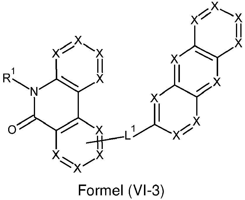
- Ferner kann vorgesehen sein, dass erfindungsgemäße Verbindungen eine der Strukturen der Formeln (VI-6), (VI-7), (VI-8) oder (VI-9) aufweisen


- Ferner kann vorgesehen sein, dass in Formeln (II), (II-1), (II-2), (II-3), (II-4), (II-5), (IV), (IV-1), (IV-2), (IV-3), (IV-6), (IV-7), (IV-8), (IV-9), (VI), (VI-1), (VI-2), (VI-3), (VI-6), (VI-7), (VI-8), (VI-9) alle X für CR1 stehen, wobei vorzugsweise höchstens 4, besonders bevorzugt höchstens 3 und speziell bevorzugt höchstens 2 der Gruppen CR1 für die X steht, ungleich der Gruppe CH ist.
- Weiterhin sind Verbindungenmit einer der Strukturen der Formeln (IIa), (IVa), oder (VIa) bevorzugt


- In einer weiterhin bevorzugten Ausführungsform können die erfindungsgemäßen Verbindungen eine der Strukturen der Formeln (Ila-1), (IIa-2), (Ila-3), (Ila-4) und/oder (Ila-5) aufweisen


- Weiterhin können die erfindungsgemäßen Verbindungen eine der Strukturen der Formeln (IVa-1), (IVa-2) oder (IVa-3) aufweisen


- Weiterhin sind Verbindungen mit einer der Strukturen der Formeln (Vla-1), (VIa-2) oder (Vla-3) bevorzugt


- Weiterhin können die erfindungsgemäßen Verbindungen eine der Strukturen der Formeln (IVa-6), (IVa-7), (IVa-8) oder (IVa-9) aufweisen

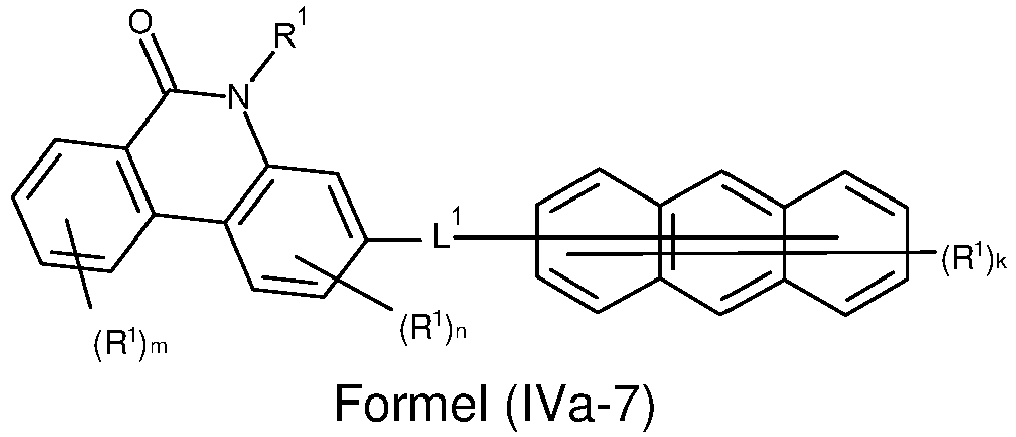


- Weiterhin sind Verbindungen mit einer der Strukturen der Formeln (Vla-6), (Vla-7), (Vla-8) oder (Vla-9) bevorzugt


- Ferner kann vorgesehen sein, dass in den Strukturen gemäß Formeln (IIa), (Ila-1), (Ila-2), (Ila-3), (Ila-4), (Ila-5), (IVa), (IVa-1), (IVa-2), (IVa-3), (IVa-6), (IVa-7), (IVa-8), (IVa-9), (VIa), (Vla-1), (Vla-2), (Vla-3), (Vla-6), (Vla-7), (VIa-8) und/oder (Vla-9) die Summe der Indices k, m, n, o und p höchstens 7, vorzugsweise höchstens 6 und besonders bevorzugt höchstens 5 beträgt.
- Weiterhin kann vorgesehen sein, dass die Substituenten R1 des aromatischen Ringsystems gemäß den Formeln (II), (II-1), (II-2), (II-3), (II-4), (II-5), (IIa), (Ila-1), (IIa-2), (Ila-3), (IIa-4), (Ila-5), (IV), (IV-1), (IV-2), (IV-3), (IV-6), (IV-7), (IV-8), (IV-9), (IVa), (IVa-1), (IVa-2), (IVa-3), (IVa-6), (IVa-7), (IVa-8), (IVa-9), (VI), (VI-1), (VI-2), (VI-3), (VI-6), (VI-7), (VI-8), (VI-9), (VIa), (Vla-1), (Vla-2), (Vla-3), (Vla-6), (Vla-7), (Vla-8) und/oder (Vla-9) mit den Ringatomen des aromatischen Ringsystems kein kondensiertes aromatisches oder heteroaromatisches Ringsystem, vorzugsweise kein kondensiertes Ringsystem bilden. Dies schließt die Bildung eines kondensierten Ringsystems mit möglichen Substituenten R2, R3 ein, die an die Reste R1 gebunden sein können. Bevorzugt kann vorgesehen sein, dass die Substituenten R1 des aromatischen Ringsystems gemäß den Formeln (II), (II-1), (II-2), (II-3), (II-4), (II-5), (IIa), (IIa-1), (IIa-2), (Ila-3), (IIa-4), (Ila-5), (IV), (IV-1), (IV-2), (IV-3), (IV-6), (IV-7), (IV-8), (IV-9), (IVa), (IVa-1), (IVa-2), (IVa-3), (IVa-6), (IVa-7), (IVa-8), (IVa-9), (VI), (VI-1), (VI-2), (VI-3), (VI-6), (VI-7), (VI-8), (VI-9), (VIa), (Vla-1), (Vla-2), (Vla-3), (Vla-6), (Vla-7), (Vla-8) und/oder (Vla-9) mit den Ringatomen des aromatischen Ringsystems kein Ringsystem bilden. Dies schließt die Bildung eines Ringsystems mit möglichen Substituenten R2, R3 ein, die an die Reste R1 gebunden sein können.
- Gemäß einer bevorzugten Ausgestaltung sind erfindungsgemäße Verbindungen durch Strukturen der Formel (II), (II-1), (II-2), (II-3), (II-4), (II-5), (IIa), (IIa-1), (IIa-2), (Ila-3), (IIa-4), (Ila-5), (IV), (IV-1), (IV-2), (IV-3), (IV-6), (IV-7), (IV-8), (IV-9), (IVa), (IVa-1), (IVa-2), (IVa-3), (IVa-6), (IVa-7), (IVa-8), (IVa-9), (VI), (VI-1), (VI-2), (VI-3), (VI-6), (VI-7), (VI-8), (VI-9), (VIa), (Vla-1), (Vla-2), (Vla-3), (Vla-6), (Vla-7), (Vla-8) und/oder (Vla-9) darstellbar. Vorzugsweise weisen erfindungsgemäße Verbindungen, besonders bevorzugt Verbindungen, mit Strukturen gemäß Formel (II), (II-1), (II-2), (II-3), (II-4), (II-5), (IIa), (IIa-1), (IIa-2), (Ila-3), (IIa-4), (Ila-5), (IV), (IV-1), (IV-2), (IV-3), (IV-6), (IV-7), (IV-8), (IV-9), (IVa), (IVa-1), (IVa-2), (IVa-3), (IVa-6), (IVa-7), (IVa-8), (IVa-9), (VI), (VI-1), (VI-2), (VI-3), (VI-6), (VI-7), (VI-8), (VI-9), (VIa), (Vla-1), (Vla-2), (Vla-3), (Vla-6), (Vla-7), (Vla-8) und/oder (Vla-9) ein Molekulargewicht von kleiner oder gleich 5000 g/mol, bevorzugt kleiner oder gleich 4000 g/mol, insbesondere bevorzugt kleiner oder gleich 3000 g/mol, speziell bevorzugt kleiner oder gleich 2000 g/mol und ganz besonders bevorzugt kleiner oder gleich 1200 g/mol auf.
- Weiterhin zeichnen sich bevorzugte erfindungsgemäße Verbindungen dadurch aus, dass diese sublimierbar sind. Diese Verbindungen weisen im Allgemeinen eine Molmasse von weniger als ca. 1200 g/mol auf.
- Wenn X für CR1 steht bzw. wenn die aromatische und/oder heteroaromatische Gruppen durch Substituenten R1 substituiert sind, dann sind diese Substituenten R1 bevorzugt gewählt aus der Gruppe bestehend aus H, D, CN, einer geradkettigen Alkylgruppe mit 1 bis 10 C-Atomen oder einer verzweigten oder cyclischen Alkylgruppe mit 3 bis 10 C-Atomen oder einer Alkenylgruppe mit 2 bis 10 C-Atomen, die jeweils mit einem oder mehreren Resten R2 substituiert sein kann, wobei eine oder mehrere nichtbenachbarte CH2-Gruppen durch O ersetzt sein können und wobei ein oder mehrere H-Atome durch D oder F ersetzt sein können, einem aromatischen oder heteroaromatischen Ringsystem mit 5 bis 24 aromatischen Ringatomen, das jeweils mit einem oder mehreren Resten R2 substituiert sein kann, bevorzugt aber unsubstituiert ist, oder einer Aralkyl- oder Heteroaralkylgruppe mit 5 bis 25 aromatischen Ringatomen, die mit einem oder mehreren Resten R2 substituiert sein kann; dabei können optional zwei Substituenten R1, die vorzugsweise an benachbarte Kohlenstoffatome gebunden sind, ein monocyclisches oder polycyclisches, aliphatisches, heteroaliphatisches, aromatisches oder heteroaromatisches Ringsystem bilden, das mit einem oder mehreren Resten R2 substituiert sein kann Besonders bevorzugt sind diese Substituenten R1 ausgewählt aus der Gruppe bestehend aus H, D, CN, einer geradkettigen Alkylgruppe mit 1 bis 8 C-Atomen, bevorzugt mit 1, 2, 3 oder 4 C-Atomen, oder einer verzweigten oder cyclischen Alkylgruppe mit 3 bis 8 C-Atomen, bevorzugt mit 3 oder 4 C-Atomen, oder einer Alkenylgruppe mit 2 bis 8 C-Atomen, bevorzugt mit 2, 3 oder 4 C-Atomen, die jeweils mit einem oder mehreren Resten R2 substituiert sein kann, bevorzugt aber unsubstituiert ist, oder einem aromatischen oder heteroaromatischen Ringsystem mit 6 bis 24 aromatischen Ringatomen, bevorzugt mit 6 bis 18 aromatischen Ringatomen, besonders bevorzugt mit 6 bis 13 aromatischen Ringatomen, das jeweils mit einem oder mehreren nicht-aromatischen Resten R1 substituiert sein kann, bevorzugt aber unsubstituiert ist; dabei können optional zwei Substituenten R1, die an dasselbe Kohlenstoffatom oder an benachbarte Kohlenstoffatome gebunden sind, ein monocyclisches oder polycyclisches, aliphatisches Ringsystem bilden, das mit einem oder mehreren Resten R2 substituiert sein kann, bevorzugt aber unsubstituiert ist.
- Ganz besonders bevorzugt sind die Substituenten R1 ausgewählt aus der Gruppe bestehend aus H oder einem aromatischen oder heteroaromatischen Ringsystem mit 6 bis 18 aromatischen Ringatomen, bevorzugt mit 6 bis 13 aromatischen Ringatomen, das jeweils mit einem oder mehreren nicht-aromatischen Resten R2 substituiert sein kann, bevorzugt aber unsubstituiert ist. Beispiele für geeignete Substituenten R1 sind ausgewählt aus der Gruppe bestehend aus Phenyl, ortho-, meta- oder para-Biphenyl, Terphenyl, insbesondere verzweigtes Terphenyl, Quaterphenyl, insbesondere verzweigtes Quaterphenyl, 1-, 2-, 3- oder 4-Fluorenyl, 1-, 2-, 3- oder 4-Spirobifluorenyl, Pyridyl, Pyrimidinyl, 1-, 2-, 3- oder 4-Dibenzofuranyl, 1-, 2-, 3- oder 4-Dibenzothienyl und 1-, 2-, 3- oder 4-Carbazolyl, die jeweils durch einen oder mehrere Reste R2 substituiert sein können, bevorzugt aber unsubstituiert sind.
- Weiterhin kann vorgesehen sein, dass in einer Struktur gemäß Formel (II), (II-1), (II-2), (II-3), (II-4), (II-5), (IIa), (Ila-1), (Ila-2), (Ila-3), (Ila-4), (Ila-5), (IV), (IV-1), (IV-2), (IV-3), (IV-6), (IV-7), (IV-8), (IV-9), (IVa), (IVa-1), (IVa-2), (IVa-3), (IVa-6), (IVa-7), (IVa-8), (IVa-9), (VI), (VI-1), (VI-2), (VI-3), (VI-6), (VI-7), (VI-8), (VI-9), (VIa), (Vla-1), (Vla-2), (Vla-3), (Vla-6), (Vla-7), (Vla-8) und/oder (Vla-9) mindestens ein Rest R1 für eine Gruppe steht, die ausgewählt ist aus den Formeln (R1-1) bis (R1- 86)


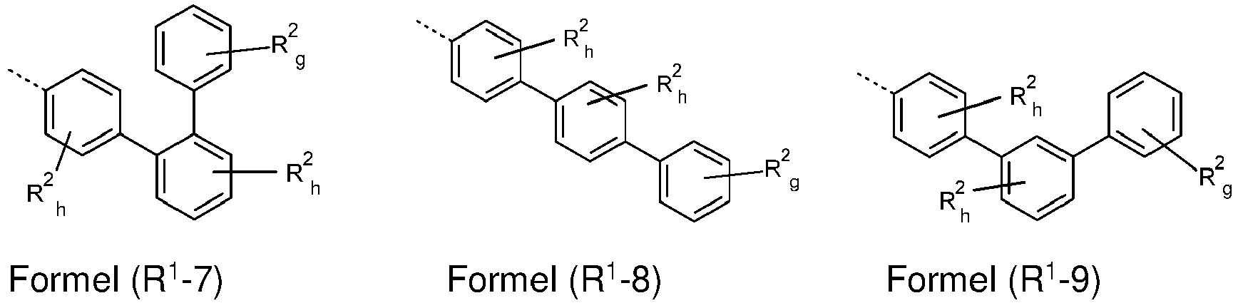
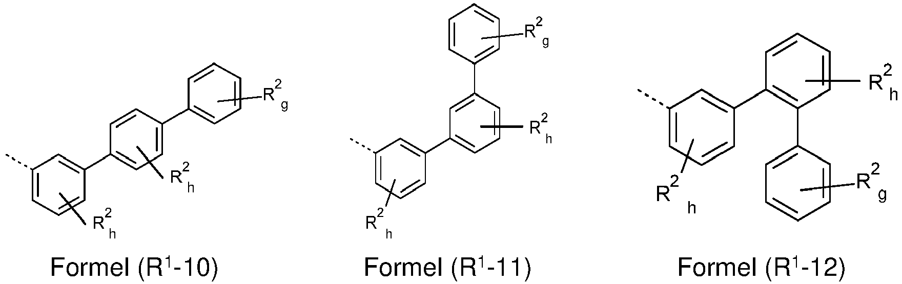

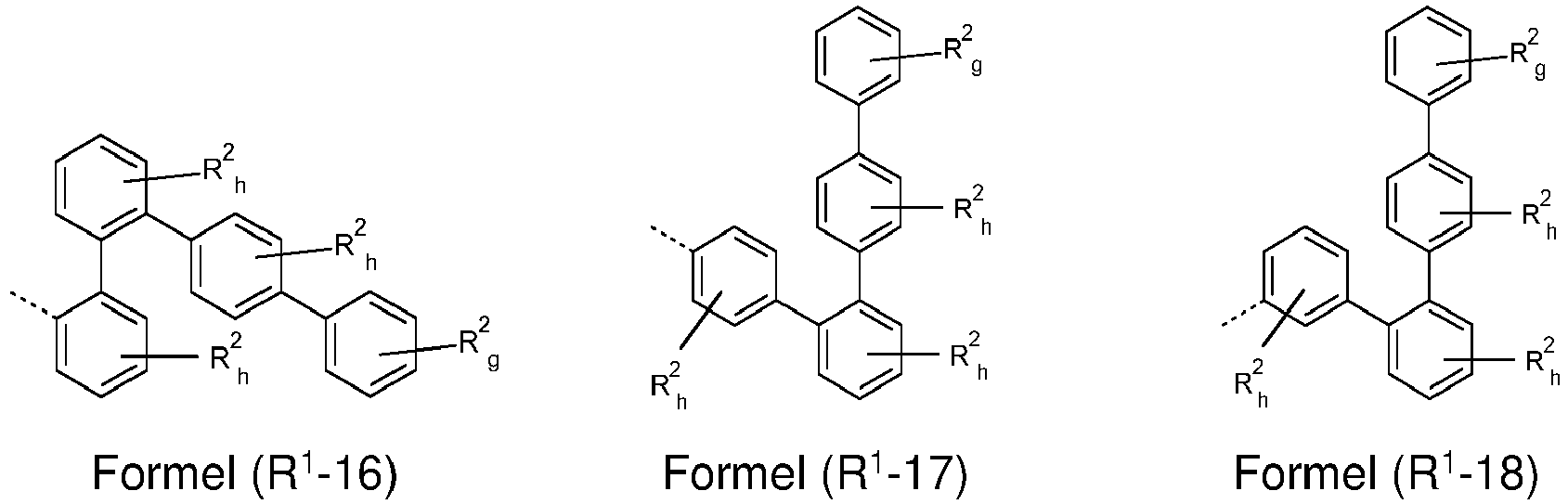


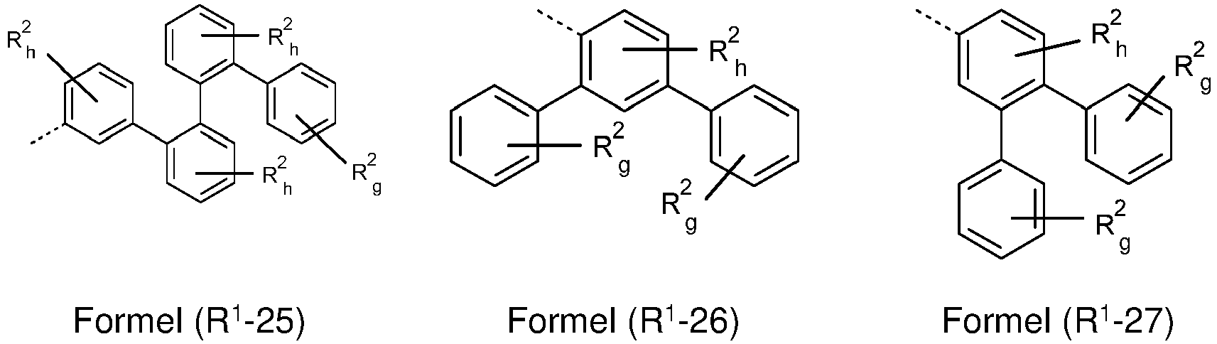


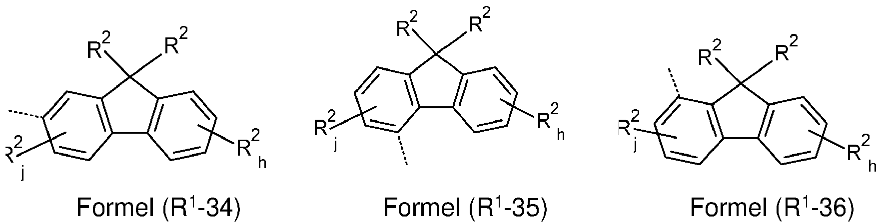


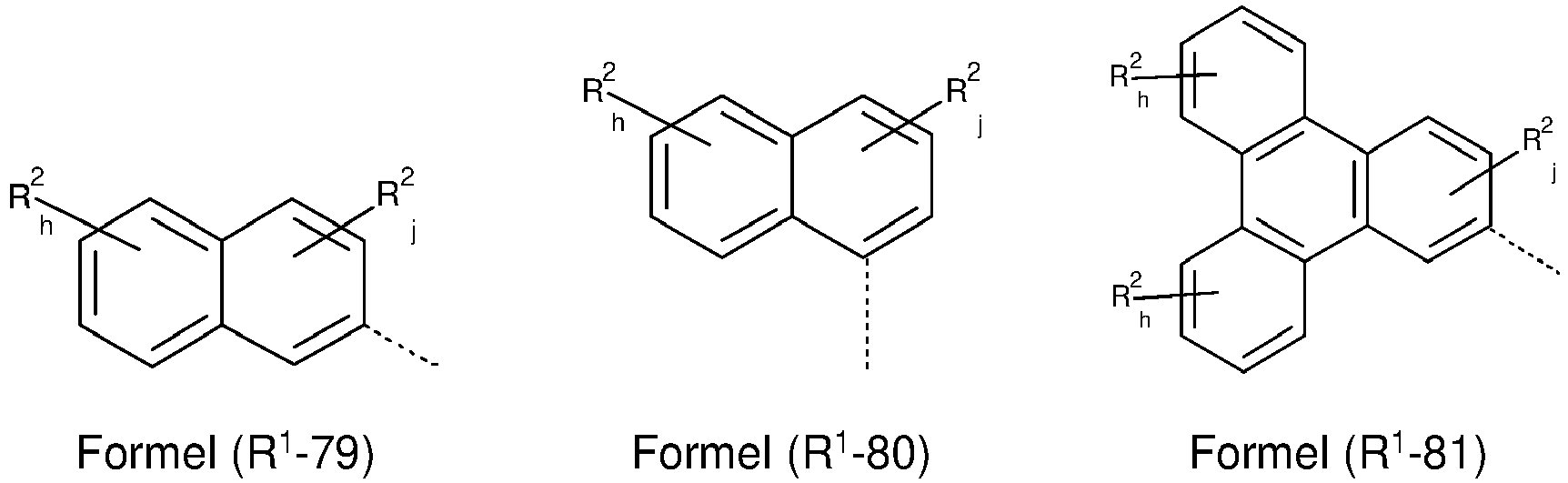


- Y
- ist O, S oder NR2, vorzugsweise O oder S;
- k
- ist bei jedem Auftreten unabhängig 0 oder 1;
- i
- ist bei jedem Auftreten unabhängig 0, 1 oder 2;
- j
- ist bei jedem Auftreten unabhängig 0, 1, 2 oder 3;
- h
- ist bei jedem Auftreten unabhängig 0, 1, 2, 3 oder 4;
- g
- ist bei jedem Auftreten unabhängig 0, 1, 2, 3, 4 oder 5;
- R2
- kann die zuvor genannte Bedeutung aufweisen und
- Vorzugsweise kann vorgesehen sein, dass die Summe der Indices i, j, h und g in den Strukturen der Formel (R1-1) bis (R1-86) jeweils höchstens 3, vorzugsweise höchstens 2 und besonders bevorzugt höchstens 1 beträgt.
- Bevorzugt bilden die Reste R2 in den Formeln (R1-1) bis (R1-86) mit den Ringatomen der Arylgruppe oder Heteroarylgruppe, an die die Reste R2 gebunden sind, kein kondensiertes aromatisches oder heteroaromatisches Ringsystem, vorzugsweise kein kondensiertes Ringsystem. Dies schließt die Bildung eines kondensierten Ringsystems mit möglichen Substituenten R3 ein, die an die Reste R2 gebunden sein können.
- Bevorzugt kann die Gruppe L1 mit dem Strukturelement mit drei anellierten aromatischen Ringen (AR) und mit dem Strukturelement mit einem aromatischen Valerolaktam (AV) eine durchgängige Konjugation ausbilden. Eine durchgängige Konjugation der aromatischen beziehungsweise heteroaromatischen Systeme wird ausgebildet sobald direkte Bindungen zwischen benachbarten aromatischen oder heteroaromatischen Ringen gebildet werden. Eine weitere Verknüpfung zwischen den zuvor genannten konjugierten Gruppen, die beispielsweise über ein S-, N- oder O-Atom oder eine Carbonylgruppe erfolgt, schadet einer Konjugation nicht. Bei einem Fluorensystem sind die beiden aromatischen Ringe unmittelbar gebunden, wobei das sp3 hybridisierte Kohlenstoffatom in Position 9 zwar eine Kondensation dieser Ringe unterbindet, jedoch eine Konjugation erfolgen kann, da dieses sp3 hybridisierte Kohlenstoffatom in Position 9 nicht zwingend zwischen dem Strukturelement mit drei anellierten aromatischen (AR) und dem Strukturelement mit einem aromatischen Valerolaktam (AV) liegt. Im Gegensatz hierzu kann bei einer zweiten Spirobifluorenstruktur eine durchgängige Konjugation ausgebildet werden, falls die Verbindung zwischen dem Strukturelement mit drei anellierten aromatischen Ringen (AR) und dem Strukturelement mit einem aromatischen Valerolaktam (AV) über die gleiche Phenylgruppe der Spirobifluorenstruktur oder über Phenylgruppen der Spirobifluorenstruktur, die unmittelbar aneinander gebunden sind und in einer Ebene liegen, erfolgt. Falls die Verbindung zwischen dem Strukturelement mit drei anellierten aromatischen Ringen (AR) und dem Strukturelement mit einem aromatischen Valerolaktam (AV) über verschiedene Phenylgruppen der zweiten Spirobifluorenstruktur erfolgt, die über das sp3 hybridisierte Kohlenstoffatom in Position 9 verbunden sind, ist die Konjugation unterbrochen.
- In einer weiteren bevorzugten Ausführungsform der Erfindung steht L1 für eine Bindung oder für ein aromatisches oder heteroaromatisches Ringsystem mit 5 bis 14 aromatischen oder heteroaromatischen Ringatomen, vorzugsweise ein aromatisches Ringsystem mit 6 bis 12 Kohlenstoffatomen, welches durch einen oder mehrere Reste R1 substituiert sein kann, bevorzugt aber unsubstituiert ist, wobei R1 die zuvor genannte Bedeutung aufweisen kann. Besonders bevorzugt steht L1 für ein aromatisches Ringsystem mit 6 bis 10 aromatischen Ringatomen oder ein heteroaromatisches Ringsystem mit 6 bis 13 heteroaromatischen Ringatomen, das jeweils durch einen oder mehrere Reste R2 substituiert sein kann, bevorzugt aber unsubstituiert ist, wobei R2 die zuvor genannte Bedeutung aufweisen kann.
- Weiterhin bevorzugt steht das unter anderem in den Strukturen gemäß Formel (II), (II-1), (II-2), (II-3), (II-4), (II-5), (IIa), (Ila-1), (Ila-2), (Ila-3), (Ila-4), (Ila-5), (IV), (IV-1), (IV-2), (IV-3), (IV-6), (IV-7), (IV-8), (IV-9), (IVa), (IVa-1), (IVa-2), (IVa-3), (IVa-6), (IVa-7), (IVa-8), (IVa-9), (VI), (VI-1), (VI-2), (VI-3), (VI-6), (VI-7), (VI-8), (VI-9), (VIa), (Vla-1), (Vla-2), (Vla-3), (Vla-6), (Vla-7), (Vla-8) und/oder (Vla-9) dargelegte Symbol L1 gleich oder verschieden bei jedem Auftreten für eine Bindung oder einen Aryl- oder Heteroarylrest mit 5 bis 24 Ringatomen, vorzugsweise 6 bis 13 Ringatomen, besonders bevorzugt 6 bis 10 Ringatomen, so dass eine aromatische oder heteroaromatische Gruppe eines aromatischen oder heteroaromatische Ringsystems direkt, d.h. über ein Atom der aromatischen oder heteroaromatische Gruppe, an das jeweilige Atom der weiteren Gruppe gebunden ist.
- Weiterhin kann vorgesehen sein, dass die unter anderem in den Strukturen gemäß Formel (II), (II-1), (II-2), (II-3), (II-4), (II-5), (IIa), (IIa-1), (IIa-2), (Ila-3), (IIa-4), (Ila-5), (IV), (IV-1), (IV-2), (IV-3), (IV-6), (IV-7), (IV-8), (IV-9), (IVa), (IVa-1), (IVa-2), (IVa-3), (IVa-6), (IVa-7), (IVa-8), (IVa-9), (VI), (VI-1), (VI-2), (VI-3), (VI-6), (VI-7), (VI-8), (VI-9), (VIa), (Vla-1), (Vla-2), (Vla-3), (Vla-6), (Vla-7), (Vla-8) und/oder (Vla-9) dargelegte Gruppe L1 ein aromatisches Ringsystem mit höchstens zwei kondensierten aromatischen und/oder heteroaromatischen Ringen, vorzugsweise kein kondensiertes aromatisches oder heteroaromatisches Ringsystem umfasst. Demgemäß sind Naphthylstrukturen gegenüber Anthracenstrukturen bevorzugt. Weiterhin sind Fluorenyl-, Spirobifluorenyl-, Dibenzofuranyl- und/oder Dibenzothienyl-Strukturen gegenüber Naphthylstrukturen bevorzugt.
- Besonders bevorzugt sind Strukturen, die keine Kondensation aufweisen, wie beispielsweise Phenyl-, Biphenyl-, Terphenyl- und/oder Quaterphenyl-Strukturen.
- Beispiele für geeignete aromatische oder heteroaromatische Ringsysteme L1 sind ausgewählt aus der Gruppe bestehend aus ortho-, meta- oder para-Phenylen, ortho-, meta- oder para-Biphenylen, Terphenylen, insbesondere verzweigtes Terphenylen, Quaterphenylen, insbesondere verzweigtes Quaterphenylen, Fluorenylen, Spirobifluorenylen, Dibenzofuranylen, Dibenzothienylen und Carbazolylen, die jeweils durch einen oder mehrere Reste R2 substituiert sein können, bevorzugt aber unsubstituiert sind.
- Ferner kann vorgesehen sein, dass die unter anderem in den Strukturen gemäß Formel (II), (II-1), (II-2), (II-3), (II-4), (II-5), (IIa), (Ila-1), (Ila-2), (Ila-3), (Ila-4), (Ila-5), (IV), (IV-1), (IV-2), (IV-3), (IV-6), (IV-7), (IV-8), (IV-9), (IVa), (IVa-1), (IVa-2), (IVa-3), (IVa-6), (IVa-7), (IVa-8), (IVa-9), (VI), (VI-1), (VI-2), (VI-3), (VI-6), (VI-7), (VI-8), (VI-9), (VIa), (Vla-1), (Vla-2), (Vla-3), (Vla-6), (Vla-7), (Vla-8) und/oder (Vla-9) dargelegte Gruppe L1 höchstens 1 Stickstoffatom, bevorzugt höchstens 2 Heteroatome, insbesondere bevorzugt höchstens ein Heteroatom und besonders bevorzugt kein Heteroatom aufweist.
- Bevorzugt sind Verbindungen umfassend Strukturen der Formeln (II), (II-1), (II-2), (II-3), (II-4), (II-5), (IIa), (IIa-1), (IIa-2), (Ila-3), (IIa-4), (Ila-5), (IV), (IV-1), (IV-2), (IV-3), (IV-6), (IV-7), (IV-8), (IV-9), (IVa), (IVa-1), (IVa-2), (IVa-3), (IVa-6), (IVa-7), (IVa-8), (IVa-9), (VI), (VI-1), (VI-2), (VI-3), (VI-6), (VI-7), (VI-8), (VI-9), (VIa), (Vla-1), (Vla-2), (Vla-3), (Vla-6), (Vla-7), (Vla-8) und/oder (Vla-9), worin die Gruppe L1 für eine Bindung oder für eine Gruppe steht, die ausgewählt ist aus den Formeln (L1-1) bis (L1-108)


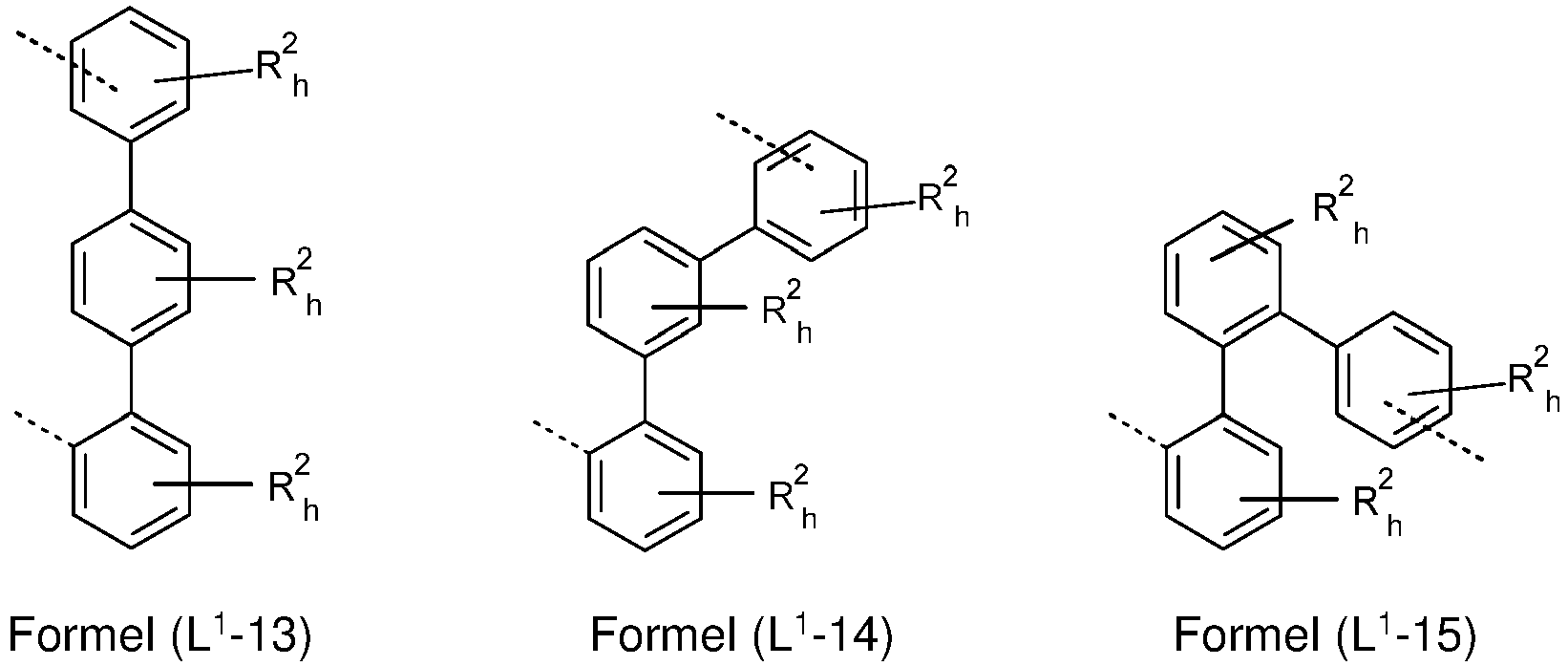


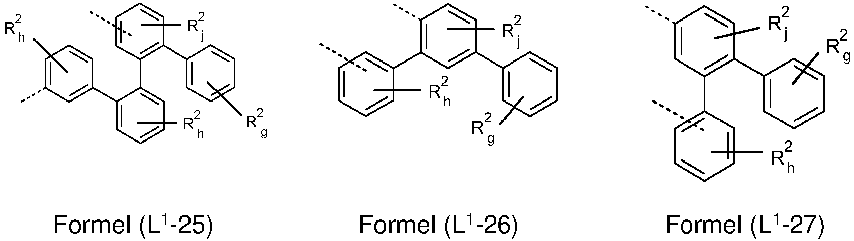
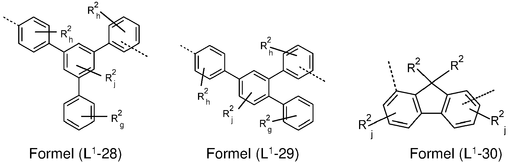


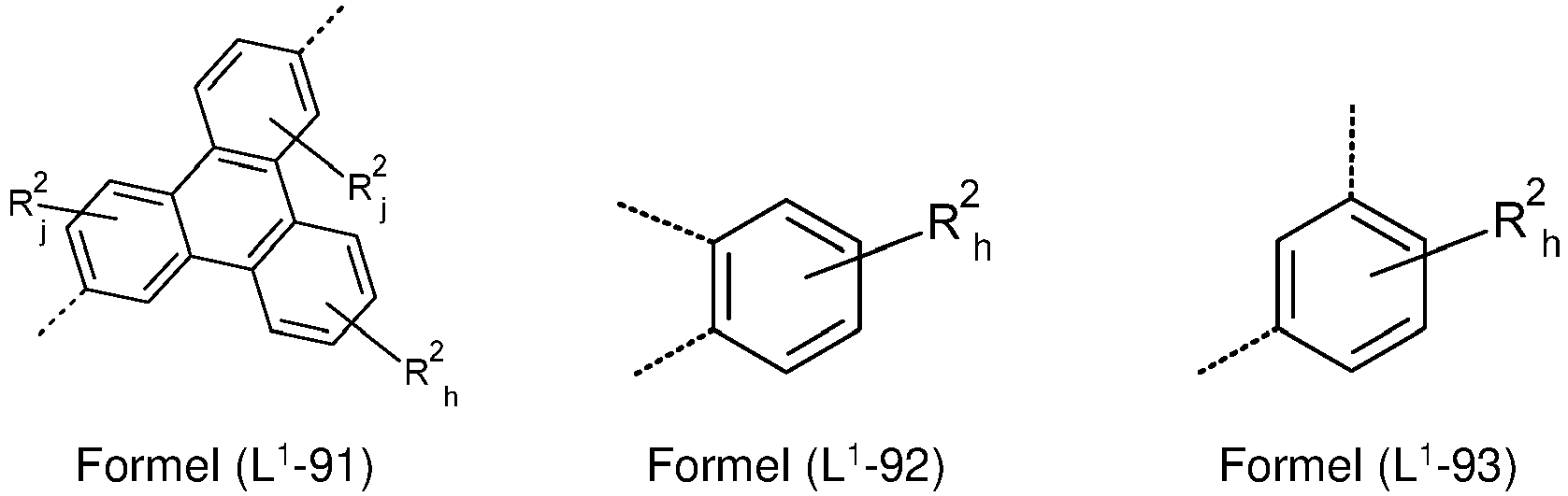


- Vorzugsweise kann vorgesehen sein, dass die Summe der Indices k, l, g, h und j in den Strukturen der Formel (L1-1) bis (L1-108) jeweils höchstens 3, vorzugsweise höchstens 2 und besonders bevorzugt höchstens 1 beträgt.
- Bevorzugte erfindungsgemäße Verbindungen umfassen eine Gruppe L', die eine Bindung darstellt oder die ausgewählt ist aus einer der Formeln (L1-1) bis (L1-78) und/oder (L1-92) bis (L1-108), bevorzugt der Formel (L1-1) bis (L1-54) und/oder (L1-92) bis (L1-108), speziell bevorzugt der Formel (L1-1) bis (L1-29) und/oder (L1-92) bis (L1-103). Mit Vorteil kann die Summe der Indices k, l, g, h und j in den Strukturen der Formeln (L1-1) bis (L1-78) und/oder (L1-92) bis (L1-108), bevorzugt der Formel (L1-1) bis (L1-54) und/oder (L1-92) bis (L1-108), speziell bevorzugt der Formel (L1-1) bis (L1-29) und/oder (L1-92) bis (L1-103) jeweils höchstens 3, vorzugsweise höchstens 2 und besonders bevorzugt höchstens 1 betragen.
- Bevorzugt bilden die Reste R2 in den Formeln (L1-1) bis (L1-108) mit den Ringatomen der Arylgruppe oder Heteroarylgruppe, an die die Reste R2 gebunden sind, kein kondensiertes aromatisches oder heteroaromatisches Ringsystem, vorzugsweise kein kondensiertes Ringsystem. Dies schließt die Bildung eines kondensierten Ringsystems mit möglichen Substituenten R3 ein, die an die Reste R2 gebunden sein können.
- In einer weiteren bevorzugten Ausführungsform der Erfindung ist R2, beispielsweise bei einer Struktur gemäß Formel (II), (IV) und/oder (VI) sowie bevorzugten Ausführungsformen dieser Strukturen oder den Strukturen, bei denen Bezug auf diese Formeln genommen wird, bei jedem Auftreten gleich oder verschieden ausgewählt aus der Gruppe bestehend aus H, D, einem aliphatischen Kohlenwasserstoffrest mit 1 bis 10 C-Atomen, bevorzugt mit 1, 2, 3 oder 4 C-Atomen, oder einem aromatischen oder heteroaromatischen Ringsystem mit 5 bis 30 aromatischen Ringatomen, bevorzugt mit 5 bis 24 aromatischen Ringatome, besonders bevorzugt mit 5 bis 13 aromatischen Ringatomen, das durch ein oder mehrere Alkylgruppen mit jeweils 1 bis 4 Kohlenstoffatomen substituiert sein kann, bevorzugt aber unsubstituiert ist.
- In einer weiteren bevorzugten Ausführungsform der Erfindung ist R3, beispielsweise bei einer Struktur gemäß Formel (II), (IV) und/oder (VI) sowie bevorzugten Ausführungsformen dieser Struktur oder den Strukturen, bei denen Bezug auf diese Formeln genommen wird, bei jedem Auftreten gleich oder verschieden ausgewählt aus der Gruppe bestehend aus H, D, F, einem aliphatischen Kohlenwasserstoffrest mit 1 bis 10 C-Atomen, bevorzugt mit 1, 2, 3 oder 4 C-Atomen, oder einem aromatischen oder heteroaromatischen Ringsystem mit 5 bis 30 aromatischen Ringatomen, bevorzugt mit 5 bis 24 aromatischen Ringatome, besonders bevorzugt mit 5 bis 13 aromatischen Ringatomen, das durch ein oder mehrere Alkylgruppen mit jeweils 1 bis 4 Kohlenstoffatomen substituiert sein kann, bevorzugt aber unsubstituiert ist.
- Ferner kann vorgesehen sein, dass die erfindungsgemäße Verbindung zwei Strukturelemente mit drei anellierten aromatischen Ringen (AR) aufweist.
- Darüber hinaus kann eine erfindungsgemäße Verbindung zwei Strukturelemente mit einem aromatischen oder heteroaromatischen Valerolaktam (AV) umfassen.
- Besonders bevorzugt sind Verbindungen der Formeln (IIa), (Ila-1), (Ila-2), (Ila-3), (Ila-4), (Ila-5), (IVa), (IVa-1), (IVa-2), (IVa-3), (IVa-6), (IVa-7), (IVa-8), (IVa-9), (VIa), (Vla-1), (Vla-2), (Vla-3), (Vla-6), (Vla-7), (Vla-8) und/oder (Vla-9), worin L1 eine Bindung darstellt und die Summe der Indices f, k, l, m, n, o und p höchstens 5, vorzugsweise höchstens 3 und besonders bevorzugt höchstens 1 beträgt.
- Weiterhin sind Verbindungen gemäß den Formeln (Ila), (Ila-1), (Ila-3), (Ila-4) und/oder (Ila-5) bevorzugt, bei denen die Gruppe L1 eine Bindung darstellt und die Summe der Indices f, k, l, m, n, o und p höchstens 5, vorzugsweise höchstens 3 und besonders bevorzugt höchstens 1 beträgt. Im Falle der Strukturen der Formeln (Ila-1), (Ila-4) und/oder (Ila-5) ist p vorzugsweise 1, wobei die Gruppe R1, für die p 1 ist, vorzugsweise ausgewählt ist aus den Gruppen (R1-1) bis (R1-86), besonders bevorzugt (R1-1) bis (R1-54).
- Ferner sind Verbindungen gemäß den Formeln (IVa-1), (IVa-2), (IVa-3), (Vla-1), (Vla-2), (Vla-3) bevorzugt, bei denen die Anbindungsstelle am Strukturelement (AV) in para-Stellung zur Bindungsstelle des Stickstoffatoms der Amidgruppe steht, wie dies in Formel (Vla-12) dargestellt ist, und bei denen die Gruppe L1 eine Bindung darstellt und die Summe der Indices m, n, o und p höchstens 5, vorzugsweise höchstens 3 und besonders bevorzugt höchstens 1 beträgt. Im Falle der Strukturen der Formel (IVa-1) ist p vorzugsweise 1, wobei die Gruppe R1, für die p 1 ist, vorzugsweise ausgewählt ist aus den Gruppen (R1-1) bis (R1-86), besonders bevorzugt (R1-1) bis (R1-54). Im Falle der Strukturen der Formeln (IVa-2), (IVa-3), ist o vorzugsweise 2, wobei die Gruppen R1, für die o 2 ist, vorzugsweise ausgewählt jeweils sind aus den Gruppen (R1-1) bis (R1-86), besonders bevorzugt (R1-1) bis (R1-54).
- Besonders bevorzugt sind Verbindungen der Formeln (Ila), (Ila-1), (Ila-2), (Ila-3), (Ila-4), (Ila-5), (IVa), (IVa-1), (IVa-2), (IVa-3), (IVa-6), (IVa-7), (IVa-8), (IVa-9), (VIa), (Vla-1), (Vla-2), (Vla-3), (Vla-6), (Vla-7), (Vla-8) und/oder (Vla-9), worin L1 eine Gruppe der Formel (L1-1) darstellt und die Summe der Indices f, k, l, m, n, o und p höchstens 7, vorzugsweise höchstens 6 und besonders bevorzugt höchstens 5 beträgt.
- Weiterhin sind Verbindungen gemäß den Formeln (Ila-1), (Ila-3), (Ila-4) und/oder (Ila-5) bevorzugt, bei denen die Gruppe L1 eine Gruppe der Formel (L1-1) darstellt und die Summe der Indices f, k, l, m, n, o und p höchstens 5, vorzugsweise höchstens 3 und besonders bevorzugt höchstens 1 beträgt. Im Falle der Strukturen der Formeln (lla-1), (Ila-4) und/oder (Ila-5) ist p vorzugsweise 1, wobei die Gruppe R1, für die p 1 ist, vorzugsweise ausgewählt ist aus den Gruppen (R1-1) bis (R1-86), besonders bevorzugt (R1-1) bis (R1-54).
- Ferner sind Verbindungen gemäß den Formeln (IVa-1), (IVa-2), (IVa-3), (Vla-1), (Vla-2), (Vla-3) bevorzugt, bei denen die Anbindungsstelle am Strukturelement (AV) in para-Stellung zur Bindungsstelle des Stickstoffatoms der Amidgruppe steht, wie dies in Formel (Vla-8) dargestellt ist, und bei denen die Gruppe L1 eine Gruppe der Formel (L1-1) darstellt und die Summe der Indices m, n, o und p höchstens 5, vorzugsweise höchstens 3 und besonders bevorzugt höchstens 1 beträgt. Im Falle der Strukturen der Formel (IVa-1) ist p vorzugsweise 1, wobei die Gruppe R1, für die p 1 ist, vorzugsweise ausgewählt ist aus den Gruppen (R1-1) bis (R1-86), besonders bevorzugt (R1-1) bis (R1-54). Im Falle der Strukturen der Formeln (IVa-2), (IVa-3), ist o vorzugsweise 2, wobei die Gruppen R1, für die o 2 ist, vorzugsweise ausgewählt jeweils sind aus den Gruppen (R1-1) bis (R1-86), besonders bevorzugt (R1-1) bis (R1-54).
- Beispiele für geeignete erfindungsgemäße Verbindungen sind die nachstehend gezeigten Strukturen gemäß den folgenden Formeln 1 bis 91, 106 bis 135, 141, 154 bis 156, 175, 179, 183 und 185:


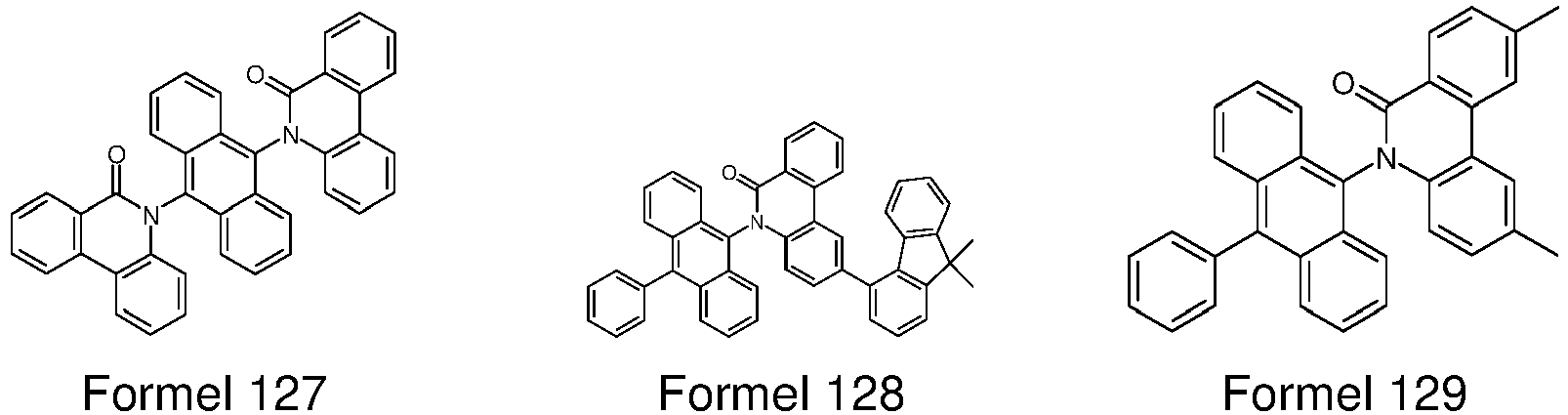


- Bevorzugte Ausführungsformen von erfindungsgemäßen Verbindungen werden in den Beispielen näher ausgeführt, wobei diese Verbindungen allein oder in Kombination mit weiteren für alle erfindungsgemäßen Verwendungszwecke eingesetzt werden können.
- Unter der Voraussetzung, dass die in Anspruch 1 genannten Bedingungen eingehalten werden, sind die oben genannten bevorzugten Ausführungsformen beliebig miteinander kombinierbar. In einer besonders bevorzugten Ausführungsform der Erfindung gelten die oben genannten bevorzugten Ausführungsformen gleichzeitig.
- Die erfindungsgemäßen Verbindungen sind prinzipiell durch verschiedene Verfahren darstellbar. Es haben sich jedoch die im Folgenden beschriebenen Verfahren als besonders geeignet herausgestellt.
- Daher ist ein weiterer Gegenstand der vorliegenden Erfindung ein Verfahren zur Herstellung der erfindungsgemäßen Verbindungen, bei dem in einer Kupplungsreaktion eine Verbindung, umfassend mindestens ein Strukturelement mit drei anellierten aromatischen Ringen (AR), mit einer Verbindung, umfassend mindestens ein Strukturelement mit einem aromatischen Valerolaktam (AV), umgesetzt wird.
- Geeignete Verbindungen mit einer aromatischen Valerolaktam-Gruppe können vielfach kommerziell erhalten werden, wobei die in den Beispielen dargelegten Ausgangsverbindungen durch bekannte Verfahren erhältlich sind, so dass hierauf verwiesen wird.
- Diese Verbindungen können durch bekannte Kupplungsreaktionen mit weiteren Arylverbindungen umgesetzt werden, wobei die notwendigen Bedingungen hierfür dem Fachmann bekannt sind und ausführliche Angaben in den Beispielen den Fachmann zur Durchführung dieser Umsetzungen unterstützen.
- Besonders geeignete und bevorzugte Kupplungsreaktionen, die alle zu C-C-Verknüpfungen und/oder C-N-Verknüpfungen führen, sind solche gemäß BUCHWALD, SUZUKI, YAMAMOTO, STILLE, HECK, NEGISHI, SONOGASHIRA und HIYAMA. Diese Reaktionen sind weithin bekannt, wobei die Beispiele dem Fachmann weitere Hinweise bereitstellen.
- Durch diese Verfahren, gegebenenfalls gefolgt von Aufreinigung, wie z. B. Umkristallisation oder Sublimation, lassen sich die erfindungsgemäßen Verbindungen, umfassend mindestens ein Strukturelement mit drei anellierten aromatischen Ringen (AR) und mindestens ein Strukturelement mit einem aromatischen Valerolaktam (AV), in hoher Reinheit, bevorzugt mehr als 99 % (bestimmt mittels 1H-NMR und/oder HPLC) erhalten.
- Die erfindungsgemäßen Verbindungen können auch geeignete Substituenten aufweisen, beispielsweise durch längere Alkylgruppen (ca. 4 bis 20 C-Atome), insbesondere verzweigte Alkylgruppen, oder gegebenenfalls substituierte Arylgruppen, beispielsweise Xylyl-, Mesityl- oder verzweigte Terphenyl- oder Quaterphenylgruppen, die eine Löslichkeit in gängigen organischen Lösemitteln bewirken, wie beispielsweise Toluol oder Xylol bei Raumtemperatur in ausreichender Konzentration zu lösen, um die Verbindungen aus Lösung verarbeiten zu können. Diese löslichen Verbindungen eignen sich besonders gut für die Verarbeitung aus Lösung, beispielsweise durch Druckverfahren. Weiterhin ist festzuhalten, dass die erfindungsgemäßen Verbindungen, umfassend mindestens ein Strukturelement mit drei anellierten aromatischen Ringen (AR) und mindestens ein Strukturelement mit einem aromatischen Valerolaktam (AV), bereits eine gesteigerte Löslichkeit in diesen Lösungsmitteln besitzen.
- Die erfindungsgemäßen Verbindungen können auch mit einem Polymer gemischt werden. Ebenso ist es möglich, diese Verbindungen kovalent in ein Polymer einzubauen. Dies ist insbesondere möglich mit Verbindungen, welche mit reaktiven Abgangsgruppen, wie Brom, lod, Chlor, Boronsäure oder Boronsäureester, oder mit reaktiven, polymerisierbaren Gruppen, wie Olefinen oder Oxetanen, substituiert sind. Diese können als Monomere zur Erzeugung entsprechender Oligomere, Dendrimere oder Polymere Verwendung finden. Die Oligomerisation bzw. Polymerisation erfolgt dabei bevorzugt über die Halogenfunktionalität bzw. die Boronsäurefunktionalität bzw. über die polymerisierbare Gruppe. Es ist weiterhin möglich, die Polymere über derartige Gruppen zu vernetzen. Die erfindungsgemäßen Verbindungen und Polymere können als vernetzte oder unvernetzte Schicht eingesetzt werden.
- Weiterer Gegenstand der Erfindung sind daher Oligomere, Polymere oder Dendrimere enthaltend ein oder mehrere der oben aufgeführten Strukturelemente mit drei anellierten aromatischen Ringen (AR) und ein oder mehrere der oben aufgeführten Strukturelemente mit einem aromatischen Valerolaktam (AV) oder erfindungsgemäße Verbindungen, wobei ein oder mehrere Bindungen der erfindungsgemäßen Verbindungen oder der Strukturen der Formel (II), (IV) und/oder (VI) zum Polymer, Oligomer oder Dendrimer vorhanden sind. Je nach Verknüpfung der Strukturen der Formel (II), (IV) und/oder (VI) bzw. der Verbindungen bilden diese daher eine Seitenkette des Oligomers oder Polymers oder sind in der Hauptkette verknüpft. Die Polymere, Oligomere oder Dendrimere können konjugiert, teilkonjugiert oder nicht-konjugiert sein. Die Oligomere oder Polymere können linear, verzweigt oder dendritisch sein. Für die Wiederholeinheiten der erfindungsgemäßen Verbindungen in Oligomeren, Dendrimeren und Polymeren gelten dieselben Bevorzugungen, wie oben beschrieben.
- Zur Herstellung der Oligomere oder Polymere werden die erfindungsgemäßen Monomere homopolymerisiert oder mit weiteren Monomeren copolymerisiert. Bevorzugt sind Copolymere, wobei die Einheiten gemäß Formel (II), (IV) und/oder (VI) bzw. die zuvor und nachfolgend ausgeführten bevorzugten Ausführungsformen zu 0.01 bis 99.9 mol%, bevorzugt 5 bis 90 mol%, besonders bevorzugt 20 bis 80 mol% vorhanden sind. Geeignete und bevorzugte Comonomere, welche das Polymergrundgerüst bilden, sind gewählt aus Fluorenen (z. B. gemäß
EP 842208 WO 2000/022026 ), Spirobifluorenen (z. B. gemäßEP 707020 EP 894107 WO 2006/061181 ), Para-phenylenen (z. B. gemäßWO 92/18552 WO 2004/070772 oderWO 2004/113468 ), Thiophenen (z. B. gemäßEP 1028136 ), Dihydrophenanthrenen (z. B. gemäßWO 2005/014689 ), cis- und trans-Indenofluorenen (z. B. gemäßWO 2004/041901 oderWO 2004/113412 ), Ketonen (z. B. gemäßWO 2005/040302 ), Phenanthrenen (z. B. gemäßWO 2005/104264 oderWO 2007/017066 ) oder auch mehreren dieser Einheiten. Die Polymere, Oligomere und Dendrimere können noch weitere Einheiten enthalten, beispielsweise Lochtransporteinheiten, insbesondere solche basierend auf Triarylaminen, und/oder Elektronentransporteinheiten. - Von besonderem Interesse sind des Weiteren erfindungsgemäße Verbindungen, die sich durch eine hohe Glasübergangstemperatur auszeichnen. In diesem Zusammenhang sind insbesondere erfindungsgemäße Verbindungen, umfassend mindestens ein Strukturelement mit drei anellierten aromatischen Ringen (AR) und mindestens ein Strukturelement mit einem aromatischen Valerolaktam (AV), bzw. die zuvor und nachfolgend ausgeführten bevorzugten Ausführungsformen, beispielsweise Verbindungen, umfassend Strukturen der allgemeinen Formel (II), (IV) und/oder (VI), bevorzugt, die eine Glasübergangstemperatur von mindestens 70 °C, beson ders bevorzugt von mindestens 110 °C, ganz besonders bevorzugt von mindestens 125 °C und insbesondere bevorzugt von mindestens 15 0 °C aufweisen, bestimmt nach DIN 51005 (Version 2005-08).
- Für die Verarbeitung der erfindungsgemäßen Verbindungen aus flüssiger Phase, beispielsweise durch Spin-Coating oder durch Druckverfahren, sind Formulierungen der erfindungsgemäßen Verbindungen erforderlich. Diese Formulierungen können beispielsweise Lösungen, Dispersionen oder Emulsionen sein. Es kann bevorzugt sein, hierfür Mischungen aus zwei oder mehr Lösemitteln zu verwenden. Geeignete und bevorzugte Lösemittel sind beispielsweise Toluol, Anisol, o-, m- oder p-Xylol, Methylbenzoat, Mesitylen, Tetralin, Veratrol, THF, Methyl-THF, THP, Chlorbenzol, Dioxan, Phenoxytoluol, insbesondere 3-Phenoxytoluol, (-)-Fenchon, 1,2,3,5-Tetramethylbenzol, 1,2,4,5-Tetramethylbenzol, 1-Methylnaphthalin, 2-Methylbenzothiazol, 2-Phenoxyethanol, 2-Pyrrolidinon, 3-Methylanisol, 4-Methylanisol, 3,4-Dimethylanisol, 3,5-Dimethylanisol, Acetophenon, α-Terpineol, Benzothiazol, Butylbenzoat, Cumol, Cyclohexanol, Cyclohexanon, Cyclohexylbenzol, Decalin, Dodecylbenzol, Ethylbenzoat, Indan, Methylbenzoat, NMP, p-Cymol, Phenetol, 1,4-Diisopropylbenzol, Dibenzylether, Diethylenglycolbutylmethylether, Triethlenglycolbutylmethylether, Diethylenglycoldibutylether, Triethylenglycoldimethylether, Diethylenglycolmonobutylether, Tripropyleneglycoldimethylether, Tetraethylenglycoldimethylether, 2-Isopropylnaphthalin, Pentylbenzol, Hexylbenzol, Heptylbenzol, Octylbenzol, 1,1-Bis(3,4-dimethylphenyl)ethan, Hexamethylindan oder Mischungen dieser Lösemittel.
- Ein weiterer Gegenstand der vorliegenden Erfindung ist daher eine Formulierung, enthaltend eine erfindungsgemäße Verbindung und mindestens eine weitere Verbindung. Die weitere Verbindung kann beispielsweise ein Lösemittel sein, insbesondere eines der oben genannten Lösemittel oder eine Mischung dieser Lösemittel. Die weitere Verbindung kann aber auch mindestens eine weitere organische oder anorganische Verbindung sein, die ebenfalls in der elektronischen Vorrichtung eingesetzt wird, beispielsweise eine emittierende Verbindung, beispielsweise ein fluoreszierender Dotand, ein phosphoreszierender Dotand oder eine Verbindung, die TADF (thermally activated delayed fluorescence) zeigt, insbesondere ein phosphoreszierender Dotand, und/oder ein weiteres Matrixmaterial. Diese weitere Verbindung kann auch polymer sein.
- Nochmals ein weiterer Gegenstand der vorliegenden Erfindung ist daher eine Zusammensetzung enthaltend eine erfindungsgemäße Verbindung und wenigstens ein weiteres organisch funktionelles Material. Funktionelle Materialen sind generell die organischen oder anorganischen Materialien, welche zwischen Anode und Kathode eingebracht sind. Vorzugsweise ist das organisch funktionelle Material ausgewählt aus der Gruppe bestehend aus fluoreszierenden Emittern, phosphoreszierenden Emittern, Host-Materialien, Elektronentransportmaterialien, Elektroneninjektionsmaterialien, Lochleitermaterialien, Lochinjektionsmaterialien, Elektronenblockiermaterialien, Lochblockiermaterialien, Wide-Band-Gap-Materialien und n-Dotanden.
- Hierbei sind insbesondere Zusammensetzungen von Interesse, die mindestens eine erfindungsgemäße Verbindung und wenigstens ein weiteres Elektroneninjektionsmaterial und/oder Elektronentransportmaterial umfasst. Das weitere Elektroneninjektionsmaterial und/oder Elektronentransportmaterial unterscheidet sich hierbei von einer erfindungsgemäßen Verbindung. Die vorliegenden Erfindung betrifft daher auch eine Zusammensetzung enthaltend wenigstens eine Verbindung, umfassend mindestens ein Strukturelement mit drei anellierten aromatischen Ringen (AR) und mindestens ein Strukturelement mit einem aromatischen Valerolaktam (AV), bzw. die zuvor und nachfolgend ausgeführten bevorzugten Ausführungsformen sowie wenigstens ein weiteres Elektroneninjektionsmaterial und/oder Elektronentransportmaterial. Vorzugsweise ist das weitere Elektroneninjektionsmaterial und/oder Elektronentransportmaterial ausgewählt aus der Gruppe der Pyridine, Pyrimidine, Triazine, Benzoxazole, Benzimidazole, Anthracene, Lactame, Dibenzofurane, Hydroxychinolinate und Alkalimetallverbindungen. Von den genannten weiteren Verbindungen sind insbesondere sind Triazine, Hydroxychinolinate und Alkalimetallverbindungen bevorzugt, wobei Hydroxychinolinate und Alkalimetallverbindungen besonders bevorzugt sind. Diese Verbindungen sind in der Fachwelt bekannt, wobei bevorzugte Alkalimetallverbindungen insbesondere Lithium enthalten. Bevorzugte Hydroxychinolinate umfassen unter anderem Zr, Al, Hf oder Li. Speziell bevorzugte weitere Elektroneninjektionsmaterialien und/oder Elektronentransportmaterialien sind Hydroxychinolinate, die Lithium enthalten, wobei Hydroxychinolinato-lithium, insbesondere 8-Hydroxychinolinato-lithium (CAS Nr. 25387-93-3) speziell bevorzugt ist.
- Hierbei kann das Verhältnis von erfindungsgemäßer Verbindung zu dem weiteren Elektroneninjektionsmaterial und/oder Elektronentransportmaterial vorzugsweise im Bereich von 1:50 bis 50:1, bevorzugt 1:20 bis 20:1, besonders bevorzugt 1:10 bis 10:1, speziell bevorzugt 1:4 bis 4:1 und ganz besonders bevorzugt 1:2 bis 2:1 vorliegen, wobei sich dieses Verhältnis auf das Volumen bezieht, falls alle Verbindungen sublimiert werden können. In anderen Fällen bezieht sich dieses Verhältnis auf das Gewicht der Substanzen.
- Die vorliegenden Erfindung betrifft weiterhin auch eine Zusammensetzung enthaltend wenigstens eine Verbindung, umfassend mindestens ein Strukturelement mit drei anellierten aromatischen Ringen (AR) und mindestens ein Strukturelement mit einem aromatischen Valerolaktam (AV), bzw. die zuvor und nachfolgend ausgeführten bevorzugten Ausführungsformen sowie wenigstens ein weiteres Matrixmaterial. Gemäß einem besonderen Aspekt der vorliegenden Erfindung weist das weitere Matrixmaterial lochtransportierende Eigenschaften auf.
- Ein weiterer Gegenstand der vorliegenden stellt eine Zusammensetzung dar, enthaltend wenigstens eine Verbindung, umfassend mindestens ein Strukturelement mit drei anellierten aromatischen Ringen (AR) und mindestens ein Strukturelement mit einem aromatischen Valerolaktam (AV), bzw. die zuvor und nachfolgend ausgeführten bevorzugten Ausführungsformen sowie wenigstens ein Wide-Band-Gap-Material, wobei unter Wide-Band-Gap-Material ein Material im Sinne der Offenbarung von
US 7,294,849 verstanden wird. Diese Systeme zeigen besondere vorteilhafte Leistungsdaten in elektrolumineszierenden Vorrichtungen. - Vorzugsweise kann die zusätzliche Verbindung eine Bandlücke (band gap) von 2,5 eV oder mehr, bevorzugt 3,0 eV oder mehr, ganz bevorzugt von 3,5 eV oder mehr aufweisen. Die Bandlücke kann unter anderem durch die Energieniveaus des highest occupied molecular orbital (HOMO) und des lowest unoccupied molecular orbital (LUMO) berechnet werden.
- Molekülorbitale, insbesondere auch das highest occupied molecular orbital (HOMO) und das lowest unoccupied molecular orbital (LUMO), deren Energieniveaus sowie die Energie des niedrigsten Triplettzustands T1 bzw. des niedrigsten angeregten Singulettzustands S1 der Materialien werden über quantenchemische Rechnungen bestimmt. Zur Berechnung organischer Substanzen ohne Metalle wird zuerst eine Geometrieoptimierung mit der Methode "Ground State/Semi-empirical/Default Spin/AM1/Charge 0/Spin Singlet" durchgeführt. Im Anschluss erfolgt auf Grundlage der optimierten Geometrie eine Energierechnung. Hierbei wird die Methode "TD-SCF/DFT/Default Spin/B3PW91" mit dem Basissatz "6-31G(d)" verwendet (Charge 0, Spin Singlet). Für metallhaltige Verbindungen wird die Geometrie über die Methode "Ground State/ Hartree-Fock/Default Spin/LanL2MB/Charge 0/Spin Singlet" optimiert. Die Energierechnung erfolgt analog zu der oben beschriebenen Methode für die organischen Substanzen mit dem Unterschied, dass für das Metallatom der Basissatz "LanL2DZ" und für die Liganden der Basissatz "6-31G(d)" verwendet wird. Aus der Energierechnung erhält man das HOMO-Energieniveau HEh bzw. LUMO-Energieniveau LEh in Hartree-Einheiten. Daraus werden die anhand von Cyclovoltammetriemessungen kalibrierten HOMO- und LUMO-Energieniveaus in Elektronenvolt wie folgt bestimmt:


- Diese Werte sind im Sinne dieser Anmeldung als HOMO- bzw. LUMO-Energieniveaus der Materialien anzusehen.
- Der niedrigste Triplettzustand T1 ist definiert als die Energie des Triplettzustands mit der niedrigsten Energie, der sich aus der beschriebenen quantenchemischen Rechnung ergibt.
- Der niedrigste angeregte Singulettzustand S1 ist definiert als die Energie des angeregten Singulettzustands mit der niedrigsten Energie, der sich aus der beschriebenen quantenchemischen Rechnung ergibt.
- Die hierin beschriebene Methode ist unabhängig von dem verwendeten Softwarepaket und liefert immer dieselben Ergebnisse. Beispiele oft benutzter Programme für diesen Zweck sind "Gaussian09W" (Gaussian Inc.) und Q-Chem 4.1 (Q-Chem, Inc.).
- Die vorliegende Erfindung betrifft auch eine Zusammensetzung umfassend wenigstens eine Verbindung, umfassend mindestens ein Strukturelement mit drei anellierten aromatischen Ringen (AR) und mindestens ein Strukturelement mit einem aromatischen Valerolaktam (AV), bzw. die zuvor und nachfolgend ausgeführten bevorzugten Ausführungsformen sowie wenigstens einen phosphoreszierende Emitter, wobei unter dem Begriff phosphoreszierende Emitter auch phosphoreszierende Dotanden verstanden werden.
- Unter einem Dotanden wird in einem System enthaltend ein Matrixmaterial und einen Dotanden diejenige Komponente verstanden, deren Anteil in der Mischung der kleinere ist. Entsprechend wird unter einem Matrixmaterial in einem System enthaltend ein Matrixmaterial und einen Dotanden diejenige Komponente verstanden, deren Anteil in der Mischung der größere ist.
- Bevorzugte phosphoreszierende Dotanden zur Verwendung in Matrix-Systemen, vorzugsweise Mixed-Matrix-Systemen sind die im Folgenden angegebenen bevorzugten phosphoreszierenden Dotanden.
- Vom Begriff phosphoreszierende Dotanden sind typischerweise Verbindungen umfasst, bei denen die Lichtemission durch einen spinverbotenen Übergang erfolgt, beispielsweise einen Übergang aus einem angeregten Triplettzustand oder einem Zustand mit einer höheren Spinquantenzahl, beispielsweise einem Quintett-Zustand.
- Als phosphoreszierende Verbindungen (= Triplettemitter) eignen sich insbesondere Verbindungen, die bei geeigneter Anregung Licht, vorzugsweise im sichtbaren Bereich, emittieren und außerdem mindestens ein Atom der Ordnungszahl größer 20, bevorzugt größer 38 und kleiner 84, besonders bevorzugt größer 56 und kleiner 80 enthalten, insbesondere ein Metall mit dieser Ordnungszahl. Bevorzugt werden als Phosphoreszenzemitter Verbindungen, die Kupfer, Molybdän, Wolfram, Rhenium, Ruthenium, Osmium, Rhodium, Iridium, Palladium, Platin, Silber, Gold oder Europium enthalten, verwendet, insbesondere Verbindungen, die Iridium oder Platin enthalten. Im Sinne der vorliegenden Erfindung werden alle lumineszierenden Verbindungen, die die oben genannten Metalle enthalten, als phosphoreszierende Verbindungen angesehen.
- Beispiele der oben beschriebenen Emitter können den Anmeldungen
WO 00/70655 WO 2001/41512 WO 2002/02714 WO 2002/15645 EP 1191613 ,EP 1191612 ,EP 1191614 ,WO 05/033244 WO 05/019373 US 2005/0258742 ,WO 2009/146770 ,WO 2010/015307 ,WO 2010/031485 ,WO 2010/054731 ,WO 2010/054728 ,WO 2010/086089 ,WO 2010/099852 ,WO 2010/102709 ,WO 2011/032626 ,WO 2011/066898 ,WO 2011/157339 ,WO 2012/007086 ,WO 2014/008982 ,WO 2014/023377 ,WO 2014/094961 ,WO 2014/094960 ,WO 2015/036074 ,WO 2015/104045 ,WO 2015/117718 ,WO 2016/015815 ,WO 2016/124304 und den noch nicht offen gelegten AnmeldungenEP 15182264.0 EP 16179378.1 EP 16186313.9 - Explizite Beispiele für phosphoreszierende Dotanden sind in der folgenden Tabelle aufgeführt.

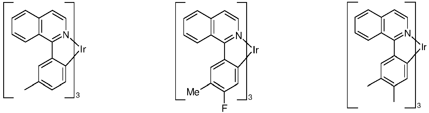


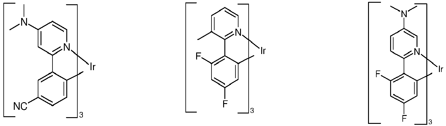
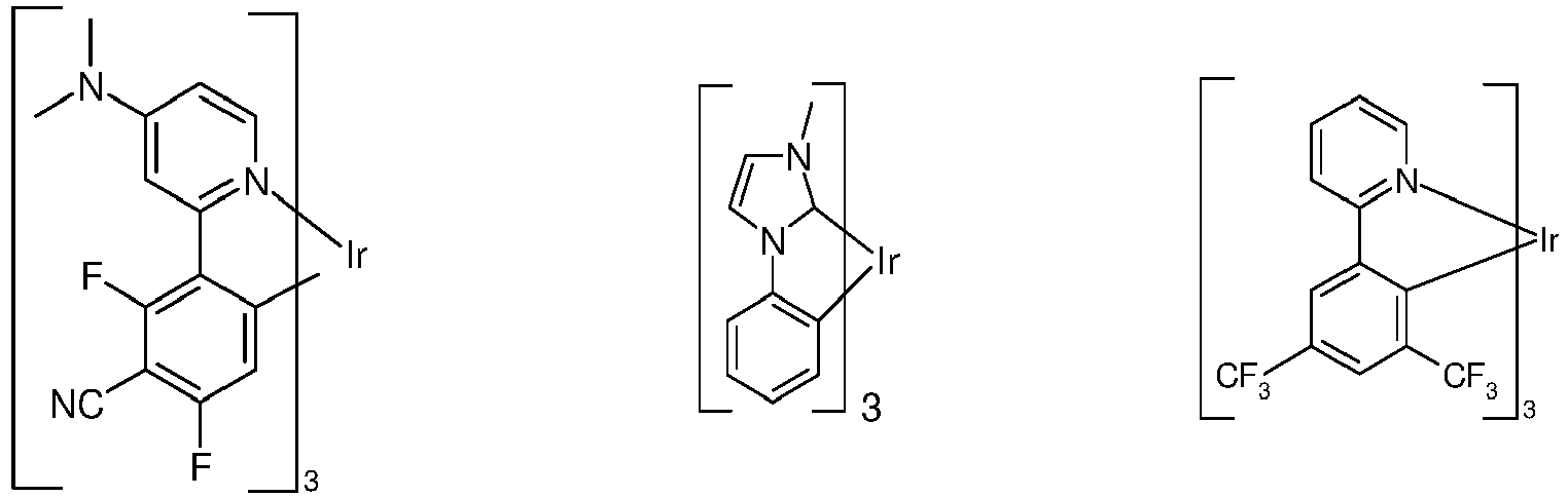


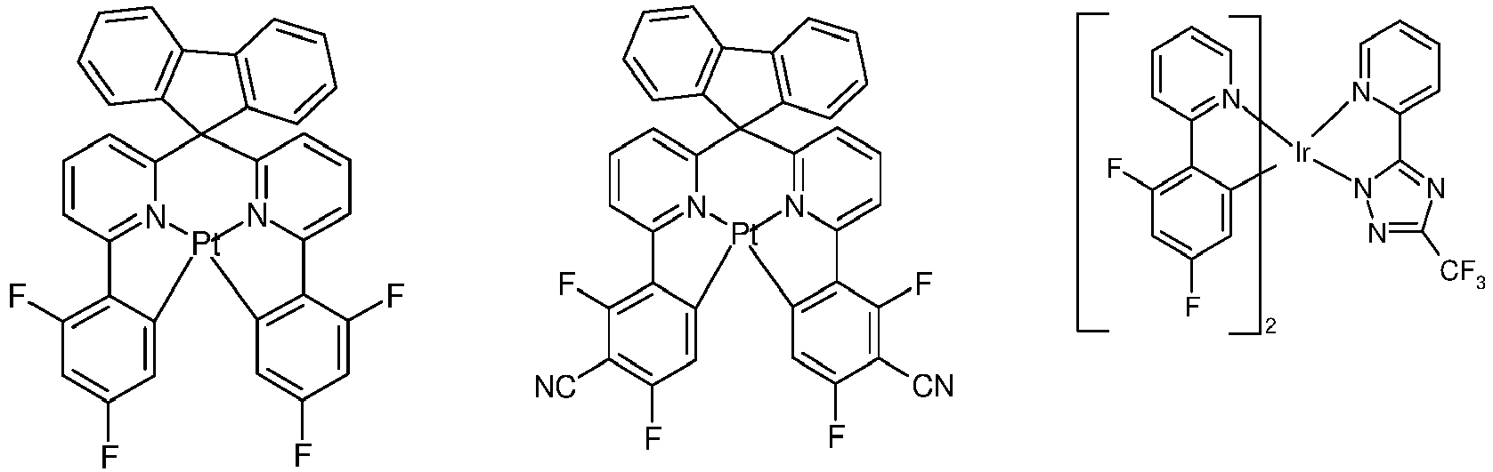


- Die oben beschriebenen Verbindungen, umfassend mindestens ein Strukturelement mit drei anellierten aromatischen Ringen (AR) und mindestens ein Strukturelement mit einem aromatischen Valerolaktam (AV), bzw. die oben aufgeführten bevorzugten Ausführungsformen, können in einer elektronischen Vorrichtung bevorzugt als aktive Komponente verwendet werden. Unter einer elektronischen Vorrichtung wird eine Vorrichtung verstanden, welche Anode, Kathode und mindestens eine zwischen Anode und Kathode liegende Schicht enthält, wobei diese Schicht mindestens eine organische bzw. metallorganische Verbindung enthält. Die erfindungsgemäße elektronische Vorrichtung enthält also Anode, Kathode und mindestens eine dazwischen liegende Schicht, welche mindestens eine Verbindung, umfassend mindestens ein Strukturelement mit drei anellierten aromatischen Ringen (AR) und mindestens ein Strukturelement mit einem aromatischen Valerolaktam (AV), enthält. Dabei sind bevorzugte elektronische Vorrichtungen ausgewählt aus der Gruppe bestehend aus organischen Elektrolumineszenzvorrichtungen (OLEDs, PLEDs), organischen integrierten Schaltungen (O-ICs), organischen Feld-Effekt-Transistoren (O-FETs), organischen Dünnfilmtransistoren (O-TFTs), organischen lichtemittierenden Transistoren (O-LETs), organischen Solarzellen (O-SCs), organischen optischen Detektoren, organischen Photorezeptoren, organischen Feld-Quench-Devices (O-FQDs), organischen elektrischen Sensoren, lichtemittierenden elektrochemischen Zellen (LECs), organischen Laserdioden (O-Laser) und "organic plasmon emitting devices" (D. M. Koller et al., Nature Photonics 2008, 1-4), bevorzugt organischen Elektrolumineszenzvorrichtungen (OLEDs, PLEDs), insbesondere phosphoreszierenden OLEDs, enthaltend in mindestens einer Schicht mindestens eine Verbindung, umfassend mindestens ein Strukturelement mit drei anellierten aromatischen Ringen (AR) und mindestens ein Strukturelement mit einem aromatischen Valerolaktam (AV). Besonders bevorzugt sind organische Elektrolumineszenzvorrichtungen. Aktive Komponenten sind generell die organischen oder anorganischen Materialien, welche zwischen Anode und Kathode eingebracht sind, beispielsweise Ladungsinjektions-, Ladungstransport- oder Ladungsblockiermaterialien, insbesondere aber Emissionsmaterialien und Matrixmaterialien.
- Eine bevorzugte Ausführungsform der Erfindung sind organische Elektrolumineszenzvorrichtungen. Die organische Elektrolumineszenzvorrichtung enthält Kathode, Anode und mindestens eine emittierende Schicht. Außer diesen Schichten kann sie noch weitere Schichten enthalten, beispielsweise jeweils eine oder mehrere Lochinjektionsschichten, Lochtransportschichten, Lochblockierschichten, Elektronentransportschichten, Elektroneninjektionsschichten, Exzitonenblockierschichten, Elektronenblockierschichten, Ladungserzeugungsschichten und/oder organische oder anorganische p/n-Übergänge. Dabei ist es möglich, dass eine oder mehrere Lochtransportschichten p-dotiert sind, beispielsweise mit Metalloxiden, wie MoOs oder WOs oder mit (per)fluorierten elektronenarmen Aromaten, und/oder dass eine oder mehrere Elektronentransportschichten n-dotiert sind. Ebenso können zwischen zwei emittierende Schichten Interlayers eingebracht sein, welche beispielsweise eine Exzitonen-blockierende Funktion aufweisen und/oder die Ladungsbalance in der Elektrolumineszenzvorrichtung steuern. Es sei aber darauf hingewiesen, dass nicht notwendigerweise jede dieser Schichten vorhanden sein muss.
- Dabei kann die organische Elektrolumineszenzvorrichtung eine emittierende Schicht enthalten, oder sie kann mehrere emittierende Schichten enthalten. Wenn mehrere Emissionsschichten vorhanden sind, weisen diese bevorzugt insgesamt mehrere Emissionsmaxima zwischen 380 nm und 750 nm auf, so dass insgesamt weiße Emission resultiert, d. h. in den emittierenden Schichten werden verschiedene emittierende Verbindungen verwendet, die fluoreszieren oder phosphoreszieren können. Insbesondere bevorzugt sind Dreischichtsysteme, wobei die drei Schichten blaue, grüne und orange oder rote Emission zeigen (für den prinzipiellen Aufbau siehe z. B.
WO 2005/011013 ) bzw. Systeme, welche mehr als drei emittierende Schichten aufweisen.. Weiterhin bevorzugt sind auch Tandem-OLEDs. Es kann sich auch um ein Hybrid-System handeln, wobei eine oder mehrere Schichten fluoreszieren und eine oder mehrere andere Schichten phosphoreszieren. - In einer bevorzugten Ausführungsform der Erfindung enthält die organische Elektrolumineszenzvorrichtung die erfindungsgemäße Verbindung, umfassend mindestens ein Strukturelement mit drei anellierten aromatischen Ringen (AR) und mindestens ein Strukturelement mit einem aromatischen Valerolaktam (AV), bzw. die oben aufgeführten bevorzugten Ausführungsformen als Matrixmaterial, vorzugsweise als elektronenleitendes Matrixmaterial in einer oder mehreren emittierenden Schichten, bevorzugt in Kombination mit einem weiteren Matrixmaterial, vorzugsweise einem lochleitenden Matrixmaterial. In einer weiteren bevorzugten Ausführungsform der Erfindung ist das weitere Matrixmaterial eine elektronentransportierende Verbindung. In nochmals einer weiteren bevorzugten Ausführungsform ist das weitere Matrixmaterial eine Verbindung mit großem Bandabstand, das nicht oder nicht in wesentlichem Umfang am Loch- und Elektronentransport in der Schicht beteiligt ist. Eine emittierende Schicht umfasst mindestens eine emittierende Verbindung.
- Geeignete Matrixmaterialien, welche in Kombination mit den Verbindungen, umfassend mindestens ein Strukturelement mit drei anellierten aromatischen Ringen (AR) und mindestens ein Strukturelement mit einem aromatischen Valerolaktam (AV), bzw. gemäß den bevorzugten Ausführungsformen eingesetzt werden können, sind aromatische Ketone, aromatische Phosphinoxide oder aromatische Sulfoxide oder Sulfone, z. B. gemäß
WO 2004/013080 ,WO 2004/093207 ,WO 2006/005627 oderWO 2010/006680 , Triarylamine, insbesondere Monoamine, z. B. gemäßWO 2014/015935 , Carbazolderivate, z. B. CBP (N,N-Biscarbazolylbiphenyl) oder die inWO 2005/039246 ,US 2005/0069729 ,JP 2004/288381 EP 1205527 oderWO 2008/086851 offenbarten Carbazolderivate, Indolocarbazolderivate, z. B. gemäßWO 2007/063754 oderWO 2008/056746 , Indenocarbazolderivate, z. B. gemäßWO 2010/136109 undWO 2011/000455 , Azacarbazolderivate, z. B. gemäßEP 1617710 ,EP 1617711 ,EP 1731584 ,JP 2005/347160 WO 2007/137725 , Silane, z. B. gemäßWO 005/111172 WO 2006/117052 , Triazinderivate, z. B. gemäßWO 2010/015306 ,WO 2007/063754 oderWO 2008/056746 , Zinckomplexe, z. B. gemäßEP 652273 WO 2009/062578 , Diazasilol- bzw. Tetraazasilol-Derivate, z. B. gemäßWO 2010/054729 , Diazaphosphol-Derivate, z. B. gemäßWO 2010/054730 , überbrückte CarbazolDerivate, z. B. gemäßUS 2009/0136779 ,WO 2010/050778 ,WO 2011/042107 ,WO 2011/088877 oderWO 2012/143080 , Triphenylenderivate, z. B. gemäßWO 2012/048781 , Lactame, z. B. gemäßWO 2011/116865 ,WO 2011/137951 oderWO 2013/064206 , 4-SpirocarbazolDerivate, z. B. gemäßWO 2014/094963 oderWO 2015/192939 oder Dibenzofuran-Derivate, z. B. gemäßWO 2015/169412 ,WO 2016/015810 ,WO 2016/023608 oder den noch nicht offen gelegten AnmeldungenEP 16158460.2 EP 16159829.7 - Bevorzugte Co-Host-Materialien sind Triarylaminderivate, insbesondere Monoamine, Indenocarbazolderivate, 4-Spirocarbazolderivate, Lactame und Carbazolderivate.
- Bevorzugte Triarylaminderivate, die als Co-Host-Materialien zusammen mit den erfindungsgemäßen Verbindungen eingesetzt werden, sind ausgewählt aus den Verbindungen der folgenden Formel (TA-1),

- Beispiele für geeignete Gruppen Ar2 sind ausgewählt aus der Gruppe bestehend aus Phenyl, ortho-, meta- oder para-Biphenyl, Terphenyl, insbesondere verzweigtes Terphenyl, Quaterphenyl, insbesondere verzweigtes Quaterphenyl, 1-, 2-, 3- oder 4-Fluorenyl, 1-, 2-, 3- oder 4-Spirobifluorenyl, Pyridyl, Pyrimidinyl, 1-, 2-, 3- oder 4-Dibenzofuranyl, 1-, 2-, 3- oder 4-Dibenzothienyl und 1-, 2-, 3- oder 4-Carbazolyl, die jeweils durch einen oder mehrere Reste R2 substituiert sein können, bevorzugt aber unsubstituiert sind.
- Bevorzugt sind die Gruppen Ar2 gleich oder verschieden bei jedem Auftreten ausgewählt aus den oben genannten Gruppen R1-1 bis R1-86, besonders bevorzugt R1-1 bis R1-54.
- In einer bevorzugten Ausführungsform der Verbindungen der Formel (TA-1) ist mindestens eine Gruppe Ar2 ausgewählt aus einer Biphenylgruppe, wobei es sich um eine ortho-, meta- oder para-Biphenylgruppe handeln kann. In einer weiteren bevorzugten Ausführungsform der Verbindungen der Formel (TA-1) ist mindestens eine Gruppe Ar2 ausgewählt aus einer Fluorengruppe oder Spirobifluorengruppe, wobei diese Gruppen jeweils in 1-, 2-, 3- oder 4-Position an das Stickstoffatom gebunden sein können. In nochmals einer weiteren bevorzugten Ausführungsform der Verbindungen der Formel (TA-1) ist mindestens eine Gruppe Ar2 ausgewählt aus einer Phenylen- oder Biphenylgruppe, wobei es sich um eine ortho-, meta- oder para-verknüpfte Gruppe handelt, die mit einer Dibenzofurangruppe, einer Dibenzothiophengruppe oder einer Carbazolgruppe, insbesondere einer Dibenzofurangruppe, substituiert ist, wobei die Dibenzofuran- bzw. Dibenzothiophengruppe über die 1-, 2-, 3- oder 4-Position mit der Phenylen- bzw. Biphenylgruppe verknüpft ist und wobei die Carbazolgruppe über die 1-, 2-, 3- oder 4-Position oder über das Stickstoffatom mit der Phenylen- bzw. Biphenylgruppe verknüpft ist.
- In einer besonders bevorzugten Ausführungsform der Verbindungen der Formel (TA-1) ist eine Gruppe Ar2 ausgewählt aus einer Fluoren- oder Spirobifluorengruppe, insbesondere einer 4-Fluoren- bzw. 4-Spirobifluorengruppe, und eine Gruppe Ar2 ist ausgewählt aus einer Biphenylgruppe, insbesondere einer para-Biphenylgruppe, oder einer Fluorengruppe, insbesondere einer 2-Fluorengruppe, und die dritte Gruppe Ar2 ist ausgewählt aus einer para-Phenylengruppe oder einer para-Biphenylgruppe, die mit einer Dibenzofurangruppe, insbesondere einer 4-Dibenzofurangruppe, oder einer Carbazolgruppe, insbesondere einer N-Carbazolgruppe oder einer 3-Carbazolgruppe, substituiert ist.
- Bevorzugte Indenocarbazolderivate, die als Co-Host-Materialien zusammen mit den erfindungsgemäßen Verbindungen eingesetzt werden, sind ausgewählt aus den Verbindungen der folgenden Formel (TA-2),

- Eine bevorzugte Ausführungsform der Verbindungen der Formel (TA-2) sind die Verbindungen der folgenden Formel (TA-2a),

- Bevorzugte 4-Spirocarbazolderivate, die als Co-Host-Materialien zusammen mit den erfindungsgemäßen Verbindungen eingesetzt werden, sind ausgewählt aus den Verbindungen der folgenden Formel (TA-3),

- Eine bevorzugte Ausführungsform der Verbindungen der Formel (TA-3) sind die Verbindungen der folgenden Formel (TA-3a),

- Bevorzugte Lactame, die als Co-Host-Materialien zusammen mit den erfindungsgemäßen Verbindungen eingesetzt werden, sind ausgewählt aus den Verbindungen der folgenden Formel (LAC-1),

- Eine bevorzugte Ausführungsform der Verbindungen der Formel (LAC-1) sind die Verbindungen der folgenden Formel (LAC-1a),

- Es kann auch bevorzugt sein, mehrere verschiedene Matrixmaterialien als Mischung einzusetzen, insbesondere mindestens ein elektronenleitendes Matrixmaterial und mindestens ein lochleitendes Matrixmaterial. Ebenso bevorzugt ist die Verwendung einer Mischung aus einem ladungstransportierenden Matrixmaterial und einem elektrisch inerten Matrixmaterial, welches nicht bzw. nicht in wesentlichem Maße am Ladungstransport beteiligt ist, wie z. B. in
WO 2010/108579 beschrieben. Weiterhin bevorzugt ist es, eine Mischung aus zwei oder mehr Triplett-Emittern zusammen mit einer Matrix einzusetzen. Dabei dient der Triplett-Emitter mit dem kürzerwelligen Emissionsspektrum als Co-Matrix für den Triplett-Emitter mit dem längerwelligen Emissionsspektrum. - Besonders bevorzugt kann eine erfindungsgemäße Verbindung, umfassend mindestens ein Strukturelement mit drei anellierten aromatischen Ringen (AR) und mindestens ein Strukturelement mit einem aromatischen Valerolaktam (AV), in einer bevorzugten Ausführungsform als Matrixmaterial in einer Emissionsschicht einer organischen elektronischen Vorrichtung, insbesondere in einer organischen elektrolumineszierenden Vorrichtung, beispielsweise in einer OLED oder OLEC, eingesetzt werden. Dabei ist das Matrixmaterial enthaltend Verbindung, umfassend mindestens ein Strukturelement mit drei anellierten aromatischen Ringen (AR) und mindestens ein Strukturelement mit einem aromatischen Valerolaktam (AV), bzw. die zuvor und nachfolgend ausgeführten bevorzugten Ausführungsformen in der elektronischen Vorrichtung in Kombination mit einem oder mehreren Dotanden, vorzugsweise phosphoreszierenden Dotanden, vorhanden.
- Der Anteil des Matrixmaterials in der emittierenden Schicht beträgt in diesem Fall zwischen 50.0 und 99.9 Vol.-%, bevorzugt zwischen 80.0 und 99.5 Vol.-% und besonders bevorzugt für fluoreszierende emittierende Schichten zwischen 92.0 und 99.5 Vol.-% sowie für phosphoreszierende emittierende Schichten zwischen 85.0 und 97.0 Vol.-%.
- Entsprechend beträgt der Anteil des Dotanden zwischen 0.1 und 50.0 Vol.-%, bevorzugt zwischen 0.5 und 20.0 Vol.-% und besonders bevorzugt für fluoreszierende emittierende Schichten zwischen 0.5 und 8.0 Vol.-% sowie für phosphoreszierende emittierende Schichten zwischen 3.0 und 15.0 Vol.-%.
- Eine emittierende Schicht einer organischen Elektrolumineszenzvorrichtung kann auch Systeme umfassend mehrere Matrixmaterialien (Mixed-Matrix-Systeme) und/oder mehrere Dotanden enthalten. Auch in diesem Fall sind die Dotanden im Allgemeinen diejenigen Materialien, deren Anteil im System der kleinere ist und die Matrixmaterialien sind diejenigen Materialien, deren Anteil im System der größere ist. In Einzelfällen kann jedoch der Anteil eines einzelnen Matrixmaterials im System kleiner sein als der Anteil eines einzelnen Dotanden.
- In einer weiteren bevorzugten Ausführungsform der Erfindung werden die Verbindung, umfassend mindestens ein Strukturelement mit drei anellierten aromatischen Ringen (AR) und mindestens ein Strukturelement mit einem aromatischen Valerolaktam (AV), bzw. die zuvor und nachfolgend ausgeführten bevorzugten Ausführungsformen als eine Komponente von Mixed-Matrix-Systemen verwendet. Die Mixed-Matrix-Systeme umfassen bevorzugt zwei oder drei verschiedene Matrixmaterialien, besonders bevorzugt zwei verschiedene Matrixmaterialien. Bevorzugt stellt dabei eines der beiden Materialien ein Material mit lochtransportierenden Eigenschaften und das andere Material ein Material mit elektronentransportierenden Eigenschaften dar. Die gewünschten elektronentransportierenden und lochtransportierenden Eigenschaften der Mixed-Matrix-Komponenten können jedoch auch hauptsächlich oder vollständig in einer einzigen Mixed-Matrix-Komponente vereinigt sein, wobei die weitere bzw. die weiteren Mixed-Matrix-Komponenten andere Funktionen erfüllen. Die beiden unterschiedlichen Matrixmaterialien können dabei in einem Verhältnis von 1:50 bis 1:1, bevorzugt 1:20 bis 1:1, besonders bevorzugt 1:10 bis 1:1 und ganz besonders bevorzugt 1:4 bis 1:1 vorliegen. Bevorzugt werden Mixed-Matrix-Systeme in phosphoreszierenden organischen Elektrolumineszenzvorrichtungen eingesetzt. Genauere Angaben zu Mixed-Matrix-Systemen sind unter anderem in der Anmeldung
WO 2010/108579 enthalten. - Ferner ist eine elektronische Vorrichtung, vorzugsweise eine organische Elektrolumineszenzvorrichtung Gegenstand der vorliegenden Erfindung, die eine oder mehrere erfindungsgemäße Verbindungen und/oder mindestens ein erfindungsgemäßes Oligomer, Polymer oder Dendrimer in einer oder mehreren elektronenleitenden Schichten umfasst, als elektronenleitende Verbindung.
- Als Kathode sind Metalle mit geringer Austrittsarbeit, Metalllegierungen oder mehrlagige Strukturen aus verschiedenen Metallen bevorzugt, wie beispielsweise Erdalkalimetalle, Alkalimetalle, Hauptgruppenmetalle oder Lanthanoide (z. B. Ca, Ba, Mg, Al, In, Mg, Yb, Sm, etc.). Weiterhin eignen sich Legierungen aus einem Alkali- oder Erdalkalimetall und Silber, beispielsweise eine Legierung aus Magnesium und Silber. Bei mehrlagigen Strukturen können auch zusätzlich zu den genannten Metallen weitere Metalle verwendet werden, die eine relativ hohe Austrittsarbeit aufweisen, wie z. B. Ag, wobei dann in der Regel Kombinationen der Metalle, wie beispielsweise Mg/Ag, Ca/Ag oder Ba/Ag verwendet werden. Es kann auch bevorzugt sein, zwischen einer metallischen Kathode und dem organischen Halbleiter eine dünne Zwischenschicht eines Materials mit einer hohen Dielektrizitätskonstante einzubringen. Hierfür kommen beispielsweise Alkalimetall- oder Erdalkalimetallfluoride, aber auch die entsprechenden Oxide oder Carbonate in Frage (z. B. LiF, Li2O, BaF2, MgO, NaF, CsF, Cs2CO3, etc.). Ebenso kommen hierfür organische Alkalimetallkomplexe in Frage, z. B. Liq (Lithiumchinolinat). Die Schichtdicke dieser Schicht beträgt bevorzugt zwischen 0.5 und 5 nm.
- Als Anode sind Materialien mit hoher Austrittsarbeit bevorzugt. Bevorzugt weist die Anode eine Austrittsarbeit größer 4.5 eV vs. Vakuum auf. Hierfür sind einerseits Metalle mit hohem Redoxpotential geeignet, wie beispielsweise Ag, Pt oder Au. Es können andererseits auch Metall/Metalloxid-Elektroden (z. B. Al/Ni/NiOx, Al/PtOx) bevorzugt sein. Für einige Anwendungen muss mindestens eine der Elektroden transparent oder teiltransparent sein, um entweder die Bestrahlung des organischen Materials (O-SC) oder die Auskopplung von Licht (OLED/PLED, O-LASER) zu ermöglichen. Bevorzugte Anodenmaterialien sind hier leitfähige gemischte Metalloxide. Besonders bevorzugt sind Indium-Zinn-Oxid (ITO) oder Indium-Zink-Oxid (IZO). Bevorzugt sind weiterhin leitfähige, dotierte organische Materialien, insbesondere leitfähige dotierte Polymere, z. B. PEDOT, PANI oder Derivate dieser Polymere. Bevorzugt ist weiterhin, wenn auf die Anode ein p-dotiertes Lochtransportmaterial als Lochinjektionsschicht aufgebracht wird, wobei sich als p-Dotanden Metalloxide, beispielsweise MoOs oder WOs, oder (per)fluorierte elektronenarme Aromaten eignen. Weitere geeignete p-Dotanden sind HAT-CN (Hexacyano-hexaazatriphenylen) oder die Verbindung NPD9 von Novaled. Eine solche Schicht vereinfacht die Lochinjektion in Materialien mit einem tiefen HOMO, also einem betragsmäßig großen HOMO.
- In den weiteren Schichten können generell alle Materialien verwendet werden, wie sie gemäß dem Stand der Technik für die Schichten verwendet werden, und der Fachmann kann ohne erfinderisches Zutun jedes dieser Materialien in einer elektronischen Vorrichtung mit den erfindungsgemäßen Materialien kombinieren.
- Die Vorrichtung wird entsprechend (je nach Anwendung) strukturiert, kontaktiert und schließlich hermetisch versiegelt, da sich die Lebensdauer derartiger Vorrichtungen bei Anwesenheit von Wasser und/oder Luft drastisch verkürzt.
- Weiterhin bevorzugt ist eine elektronischen Vorrichtung, insbesondere eine organische Elektrolumineszenzvorrichtung, welche dadurch gekennzeichnet ist, dass eine oder mehrere Schichten mit einem Sublimationsverfahren beschichtet werden. Dabei werden die Materialien in Vakuum-Sublimationsanlagen bei einem Anfangsdruck von üblicherweise kleiner 10-5 mbar, bevorzugt kleiner 10-6 mbar aufgedampft. Es ist auch möglich, dass der Anfangsdruck noch geringer oder noch höher ist, beispielsweise kleiner 10-7 mbar.
- Bevorzugt ist ebenfalls eine elektronischen Vorrichtung, insbesondere eine organische Elektrolumineszenzvorrichtung, welche dadurch gekennzeichnet ist, dass eine oder mehrere Schichten mit dem OVPD (Organic Vapour Phase Deposition) Verfahren oder mit Hilfe einer Trägergassublimation beschichtet werden. Dabei werden die Materialien bei einem Druck zwischen 10-5 mbar und 1 bar aufgebracht. Ein Spezialfall dieses Verfahrens ist das OVJP (Organic Vapour Jet Printing) Verfahren, bei dem die Materialien direkt durch eine Düse aufgebracht und so strukturiert werden (z. B. M. S. Arnold et al., Appl. Phys. Lett. 2008, 92, 053301).
- Weiterhin bevorzugt ist eine elektronischen Vorrichtung, insbesondere eine organische Elektrolumineszenzvorrichtung, welche dadurch gekennzeichnet ist, dass eine oder mehrere Schichten aus Lösung, wie z. B. durch Spincoating, oder mit einem beliebigen Druckverfahren, wie z. B. Siebdruck, Flexodruck, Offsetdruck oder Nozzle-Printing, besonders bevorzugt aber LITI (Light Induced Thermal Imaging, Thermotransferdruck) oder Ink-Jet Druck (Tintenstrahldruck), hergestellt werden. Hierfür sind lösliche Verbindungen nötig, welche beispielsweise durch geeignete Substitution erhalten werden.
- Die elektronischen Vorrichtung, insbesondere die organische Elektrolumineszenzvorrichtung kann auch als Hybridsystem hergestellt werden, indem eine oder mehrere Schichten aus Lösung aufgebracht werden und eine oder mehrere andere Schichten aufgedampft werden. So ist es beispielsweise möglich, eine emittierende Schicht enthaltend eine erfindungsgemäße Verbindung, umfassend mindestens ein Strukturelement mit drei anellierten aromatischen Ringen (AR) und mindestens ein Strukturelement mit einem aromatischen Valerolaktam (AV), und ein Matrixmaterial aus Lösung aufzubringen und darauf eine Lochblockierschicht und/oder eine Elektronentransportschicht im Vakuum aufzudampfen.
- Diese Verfahren sind dem Fachmann generell bekannt und können von ihm ohne Probleme auf elektronischen Vorrichtungen, insbesondere organische Elektrolumineszenzvorrichtungen enthaltend erfindungsgemäße Verbindungen, umfassend mindestens ein Strukturelement mit drei anellierten aromatischen Ringen (AR) und mindestens ein Strukturelement mit einem aromatischen Valerolaktam (AV), bzw. die oben aufgeführten bevorzugten Ausführungsformen angewandt werden.
- Die erfindungsgemäßen elektronischen Vorrichtungen, insbesondere organische Elektrolumineszenzvorrichtungen, zeichnen sich durch einen oder mehrere der folgenden überraschenden Vorteile gegenüber dem Stand der Technik aus:
- 1. Elektronische Vorrichtungen, insbesondere organische Elektrolumineszenzvorrichtungen enthaltend Verbindungen, Oligomere, Polymere oder Dendrimere mit mindestens einem Strukturelement, enthaltend drei anellierte aromatische Ringe (AR) und mit mindestens einem Strukturelement, enthaltend mindestens ein aromatisches Valerolaktam (AV), bzw. die zuvor und nachfolgend ausgeführten bevorzugten Ausführungsformen, insbesondere als elektronenleitende Materialien, weisen eine sehr gute Lebensdauer auf.
- 2. Elektronische Vorrichtungen, insbesondere organische Elektrolumineszenzvorrichtungen enthaltend Verbindungen, Oligomere, Polymere oder Dendrimere mit mindestens einem Strukturelement, enthaltend drei anellierte aromatische Ringe (AR) und mit mindestens einem Strukturelement, enthaltend mindestens ein aromatisches Valerolaktam (AV), bzw. die zuvor und nachfolgend ausgeführten bevorzugten Ausführungsformen weisen als elektronenleitende Materialien, Elektroneninjektionsmaterialien und/oder Hostmaterialien eine hervorragende Effizienz auf. Insbesondere ist die Effizienz deutlich höher gegenüber analogen Verbindungen, die keine Struktureinheiten gemäß (AV) oder (AR) enthalten. Hierbei bewirken erfindungsgemäßen Verbindungen, Oligomere, Polymere oder Dendrimere mit mindestens einem Strukturelement, enthaltend drei anellierte aromatische Ringe (AR) und mit mindestens einem Strukturelement, enthaltend mindestens ein aromatisches Valerolaktam (AV), bzw. die zuvor und nachfolgend ausgeführten bevorzugten Ausführungsformen eine geringe Betriebsspannung bei Verwendung in elektronischen Vorrichtungen. Hierbei bewirken diese Verbindungen insbesondere einen geringen Roll-off, d.h. einen geringen Abfall der Leistungseffizienz der Vorrichtung bei hohen Leuchtdichten.
- 3. Die erfindungsgemäßen Verbindungen, Oligomere, Polymere oder Dendrimere mit mindestens einem Strukturelement, enthaltend drei anellierte aromatische Ringe (AR) und mit mindestens einem Strukturelement, enthaltend mindestens ein aromatisches Valerolaktam (AV), bzw. die zuvor und nachfolgend ausgeführten bevorzugten Ausführungsformen zeigen eine sehr hohe Stabilität und führen zu Verbindungen mit einer sehr hohen Lebensdauer.
- 4. Mit Verbindungen, Oligomeren, Polymeren oder Dendrimeren mit mindestens einem Strukturelement, enthaltend drei anellierte aromatische Ringe (AR) und mit mindestens einem Strukturelement, enthaltend mindestens ein aromatisches Valerolaktam (AV), bzw. die zuvor und nachfolgend ausgeführten bevorzugten Ausführungsformen kann in elektronischen Vorrichtungen, insbesondere organische Elektrolumineszenzvorrichtungen die Bildung von optischen Verlustkanäle vermieden werden. Hierdurch zeichnen sich diese Vorrichtungen durch eine hohe PL- und damit hohe EL-Effizienz von Emittern bzw. eine ausgezeichnete Energieübertragung der Matrices auf Dotanden aus.
- 5. Die Verwendung von Verbindungen, Oligomeren, Polymeren oder Dendrimeren mit mindestens einem Strukturelement, enthaltend drei anellierte aromatische Ringe (AR) und mit mindestens einem Strukturelement, enthaltend mindestens ein aromatisches Valerolaktam (AV), bzw. die zuvor und nachfolgend ausgeführten bevorzugten Ausführungsformen in Schichten elektronischer Vorrichtungen, insbesondere organischer Elektrolumineszenzvorrichtungen führt zu einer hohen Mobilität der Elektronenleiterstrukturen.
- 6. Verbindungen, Oligomere, Polymere oder Dendrimere mit mindestens einem Strukturelement, enthaltend drei anellierte aromatische Ringe (AR) und mit mindestens einem Strukturelement, enthaltend mindestens ein aromatisches Valerolaktam (AV), bzw. die zuvor und nachfolgend ausgeführten bevorzugten Ausführungsformen zeichnen sich durch eine ausgezeichnete thermische Stabilität aus, wobei Verbindungen mit einer Molmasse von weniger als ca. 1200 g/mol gut sublimierbar sind.
- 7. Verbindungen, Oligomere, Polymere oder Dendrimere mit mindestens einem Strukturelement, enthaltend drei anellierte aromatische Ringe (AR) und mit mindestens einem Strukturelement, enthaltend mindestens ein aromatisches Valerolaktam (AV), bzw. die zuvor und nachfolgend ausgeführten bevorzugten Ausführungsformen weisen eine ausgezeichnete Glasfilmbildung auf.
- 8. Verbindungen, Oligomere, Polymere oder Dendrimere mit mindestens einem Strukturelement, enthaltend drei anellierte aromatische Ringe (AR) und mit mindestens einem Strukturelement, enthaltend mindestens ein aromatisches Valerolaktam (AV), bzw. die zuvor und nachfolgend ausgeführten bevorzugten Ausführungsformen bilden aus Lösungen sehr gute Filme.
- 9. Die Verbindungen, Oligomere, Polymere oder Dendrimere, umfassend mindestens ein Strukturelement mit drei anellierten aromatischen Ringen (AR) und mindestens ein Strukturelement mit einem aromatischen Valerolaktam (AV), bzw. die zuvor und nachfolgend ausgeführten bevorzugten Ausführungsformen weisen ein überraschend hohes Triplett-Niveau T1 auf, wobei dies insbesondere Verbindungen gilt, die als elektronenleitende Materialien eingesetzt werden.
- Diese oben genannten Vorteile gehen nicht mit einer Verschlechterung der weiteren elektronischen Eigenschaften einher.
- Die erfindungsgemäßen Verbindungen und Mischungen eignen sich für die Verwendung in einer elektronischen Vorrichtung. Dabei wird unter einer elektronischen Vorrichtung eine Vorrichtung verstanden, welche mindestens eine Schicht enthält, die mindestens eine organische Verbindung enthält. Das Bauteil kann dabei aber auch anorganische Materialien enthalten oder auch Schichten, welche vollständig aus anorganischen Materialien aufgebaut sind.
- Ein weiterer Gegenstand der vorliegenden Erfindung ist daher die Verwendung der erfindungsgemäßen Verbindungen oder Mischungen in einer elektronischen Vorrichtung, insbesondere in einer organischen Elektrolumineszenzvorrichtung.
- Ein nochmals weiterer Gegenstand der vorliegenden Erfindung ist die Verwendung einer erfindungsgemäßen Verbindung und/oder eines erfindungsgemäßen Oligomers, Polymers oder Dendrimers in einer elektronischen Vorrichtung als Hostmaterial, Lochblockiermaterial, Elektroneninjektionsmaterial und/oder Elektronentransportmaterial, vorzugsweise als Hostmaterial und/oder Elektronentransportmaterial. Besonders bevorzugt kann eine erfindungsgemäße Verbindung in Kombination mit einem weiteren Elektroneninjektionsmaterial und/oder Elektronentransportmaterial in einer elektronenleitenden Schicht und/oder Elektroneninjektionsschicht eingesetzt werden, wie dies zuvor in Zusammenhang mit einer erfindungsgemäßen Zusammensetzung dargelegt wurde.
- Nochmals ein weiterer Gegenstand der vorliegenden Erfindung ist eine elektronische Vorrichtung enthaltend mindestens eine der oben ausgeführten erfindungsgemäßen Verbindungen oder Mischungen. Dabei gelten die oben für die Verbindung ausgeführten Bevorzugungen auch für die elektronischen Vorrichtungen. Besonders bevorzugt ist eine elektronische Vorrichtung ausgewählt aus der Gruppe bestehend aus organischen Elektrolumineszenzvorrichtungen (OLEDs, PLEDs), organischen integrierten Schaltungen (O-ICs), organischen Feld-Effekt-Transistoren (O-FETs), organischen Dünnfilmtransistoren (O-TFTs), organischen lichtemittierenden Transistoren (O-LETs), organischen Solarzellen (O-SCs), organischen optischen Detektoren, organischen Photorezeptoren, organischen Feld-Quench-Devices (O-FQDs), organischen elektrischen Sensoren, lichtemittierenden elektrochemischen Zellen (LECs), organischen Laserdioden (O-Laser) und "organic plasmon emitting devices" (D. M. Koller et al., Nature Photonics 2008, 1-4), bevorzugt organischen Elektrolumineszenzvorrichtungen (OLEDs, PLEDs), insbesondere phosphoreszierenden OLEDs.
- In einer weiteren Ausführungsform der Erfindung enthält die erfindungsgemäße organische Elektrolumineszenzvorrichtung keine separate Lochinjektionsschicht und/oder Lochtransportschicht und/oder Lochblockierschicht und/oder Elektronentransportschicht, d. h. die emittierende Schicht grenzt direkt an die Lochinjektionschicht oder die Anode an, und/ oder die emittierende Schicht grenzt direkt an die Elektronentransportschicht oder die Elektroneninjektionsschicht oder die Kathode an, wie zum Beispiel in
WO 2005/053051 beschrieben. Weiterhin ist es möglich, einen Metallkomplex, der gleich oder ähnlich dem Metallkomplex in der emittierenden Schicht ist, direkt angrenzend an die emittierende Schicht als Lochtransport- bzw. Lochinjektionsmaterial zu verwenden, wie z. B. inWO 2009/030981 beschrieben. - Weiterhin ist es möglich, die erfindungsgemäßen Verbindungen in einer Lochblockier- oder Elektronentransportschicht einzusetzen. Dies gilt insbesondere für erfindungsgemäße Verbindungen, die keine Carbazolstruktur aufweisen. Diese können bevorzugt auch mit einer oder mehreren weiteren elektronentransportierenden Gruppen substituiert sein, beispielsweise Benzimidazolgruppen.
- In den weiteren Schichten der erfindungsgemäßen organischen Elektrolumineszenzvorrichtung können alle Materialien verwendet werden, wie sie üblicherweise gemäß dem Stand der Technik eingesetzt werden. Der Fachmann kann daher ohne erfinderisches Zutun alle für organische Elektrolumineszenzvorrichtungen bekannten Materialien in Kombination mit den erfindungsgemäßen Verbindungen bzw. gemäß den bevorzugten Ausführungsformen einsetzen.
- Die erfindungsgemäßen Verbindungen weisen bei Verwendung in organischen Elektrolumineszenzvorrichtungen generell sehr gute Eigenschaften auf. Insbesondere ist bei Verwendung der erfindungsgemäßen Verbindungen in organischen Elektrolumineszenzvorrichtungen die Lebensdauer wesentlich besser im Vergleich zu ähnlichen Verbindungen gemäß dem Stand der Technik. Dabei sind die weiteren Eigenschaften der organischen Elektrolumineszenzvorrichtung, insbesondere die Effizienz und die Spannung, ebenfalls besser oder zumindest vergleichbar.
- Es sei darauf hingewiesen, dass Variationen der in der vorliegenden Erfindung beschriebenen Ausführungsformen unter den Umfang dieser Erfindung fallen. Jedes in der vorliegenden Erfindung offenbarte Merkmal kann, sofern dies nicht explizit ausgeschlossen wird, durch alternative Merkmale, die demselben, einem äquivalenten oder einem ähnlichen Zweck dienen, ausgetauscht werden. Somit ist jedes in der vorliegenden Erfindung offenbartes Merkmal, sofern nichts anderes gesagt wurde, als Beispiel einer generischen Reihe oder als äquivalentes oder ähnliches Merkmal zu betrachten.
- Alle Merkmale der vorliegenden Erfindung können in jeder Art miteinander kombiniert werden, es sei denn dass sich bestimmte Merkmale und/oder Schritte sich gegenseitig ausschließen. Dies gilt insbesondere für bevorzugte Merkmale der vorliegenden Erfindung. Gleichermaßen können Merkmale nicht wesentlicher Kombinationen separat verwendet werden (und nicht in Kombination).
- Es sei ferner darauf hingewiesen, dass viele der Merkmale, und insbesondere die der bevorzugten Ausführungsformen der vorliegenden Erfindung selbst erfinderisch und nicht lediglich als Teil der Ausführungsformen der vorliegenden Erfindung zu betrachten sind. Für diese Merkmale kann ein unabhängiger Schutz zusätzlich oder alternativ zu jeder gegenwärtig beanspruchten Erfindung begehrt werden.
- Die mit der vorliegenden Erfindung offengelegte Lehre zum technischen Handeln kann abstrahiert und mit anderen Beispielen kombiniert werden.
- Die Erfindung wird durch die nachfolgenden Beispiele näher erläutert, ohne sie dadurch einschränken zu wollen.
- Der Fachmann kann aus den Schilderungen ohne erfinderisches Zutun weitere erfindungsgemäße elektronische Vorrichtungen herstellen und somit die Erfindung im gesamten beanspruchten Bereich ausführen.
-

- In einem Vierhalskolben werden 20.0g (73.0mmol, 1.00eq) 2-Bromo-5H-phenanthridin-6-on [27353-48-6] 1 zusammen mit 22.2g (87.6mmol, 1.20eq) Bis(pinacolato)diboran [73183-34-3] 2 und 21.5g (219mmol, 3.00eq) Kaliumacetat in 800ml Dioxan gelöst und mit Argon inertisiert. Anschließend werden 1.79g (2.19mmol, 0.03eq) 1,1-Bis(diphenylphosphino)ferrocen-dichloropalladium(II)-Komplex [95464-05-4] zugegeben und das Reaktionsgemisch bei 115°C Badtem peratur über Nacht gerührt. Nach beendeter Reaktion wird der Ansatz auf Raumtemperatur abgekühlt und das Lösungsmittel am Rotationsverdampfer entfernt. Der Rückstand wird in 250ml Dichlormethan aufgenommen und mit 250ml Wasser ausgeschüttelt. Die wässrige Phase wird dreimal mit 250ml Dichlormethan extrahiert, die vereinten organischen Phasen über Natriumsulfat getrocknet und das Lösungsmittel am Rotationsverdampfer entfernt. Der erhaltene Feststoff wird mit Ethanol bei 60°C ausgewaschen. Nach Trocknung werden 20.6g (64.0mmol, 88%) des gewünschten Produkts 3 erhalten.
-
Verbin-dung Edukt Produkt Aus-beute [%] 3b 

82 3c 

97 3d 

66 3e 

45 3f 

78 3g 

47 3h 

33 3i 

93 3j 

68 3k 

27 3l 

95 3m 

74 - In einem Vierhalskolben werden 14.4g (44.9mmol, 1.00eq) der Zwischenstufe 3, 15.7g (47.1 mmol, 1.05eq) 9-Brom-10-phenylanthracen [23674-20-6] und 4.80g (44.9mmol, 1.00eq) Natriumcarbonat in 185ml Toluol, 375ml 1,4-Dioxan und 375ml Wasser vorgelegt und das Gemisch mit Argon entgast. Anschließend werden 1.03g (0.891 mmol, 0.02eq) Tetrakis(triphenylphosphin)-palladium(0) [14221-01-3] zugegeben und der Ansatz bei 120°C über Nacht gerührt. Nach beendeter Reaktion wird der ausgefallene Feststoff mit Wasser und Ethanol gewaschen und im Vakuumtrockenschrank getrocknet. Es werden 11.9g (26.7mmol, 59%) der gewünschten Zielverbindung 5 erhalten.
-
Verb. Edukt Edukt Produkt Ausb. [%] 5b 


43% 5c 
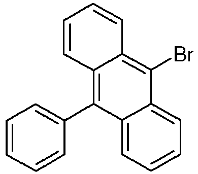

47% 5d 


53% 5e 


37% 5f 


42% 5g 
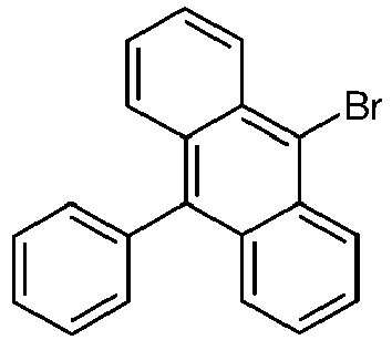

51% 5h 


53% 5i 


47% 5j 


59% 5k 


57% 5l 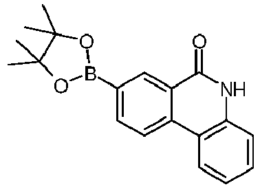


53% 5m 


37% - 11.1g (24.8mmol, 1.00eq) 2-(10-Phenyl-anthracen-9-yl)-5H-phenanthridin-6-on 5, 21.3ml (128mmol, 5.2eq) 3-Bromobiphenyl [2113-57-7]und 7.20g Kaliumcarbonat (52.1mmol, 2.10eq) Kaliumcarbonat werden in 220ml getrocknetem DMF vorgelegt und mit Argon inertisiert. Anschließend werden 0.62g (2.7 mmol, 0.11eq) 1,3-Di(2-pyridyl)-1,3-propandion und 0.52g (2.7mmol, 0.11eq) Kupfer(I)-iodid zugegeben und das Gemisch für drei Tage bei 140°C erhitzt. Nach beendeter Reaktio n wird der Ansatz vorsichtig am Rotationsverdampfer eingeengt, der ausgefallene Feststoff abgesaugt und mit Wasser und Ethanol gewaschen. Das Rohprodukt wird zweimal mittels Heißextraktor (Toluol/Heptan 1:1) aufgereinigt und der erhaltene Feststoff aus einem Toluol umkristallisiert. Nach Sublimation werden 5.3g (8.8mmol, 36%) der gewünschten Zielverbindung 7 erhalten.
-
Verb. Edukt Edukt Produkt Ausb. [%] 7b 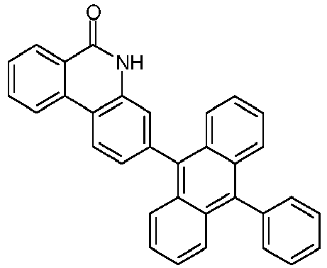


42% 7c 


47% 7d 


53% 7e 


51% 7f 


47% 7g 

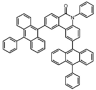
49% 7h 

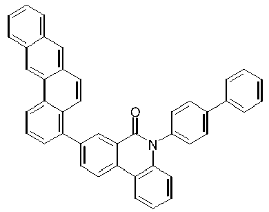
59% 7i 


42% 7j 


59% 7k 
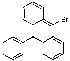
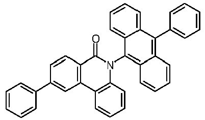
52% 7l 


41% 7m 

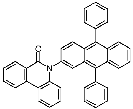
40% -

- In 200 ml wasserfreiem Toluol werden 20 g (86 mmol) E2, 11.4 g (94 mmol) E1, 23.6 g (171 mmol) Kaliumcarbonat, 1.72 g (20 mmol) N,N'-dimethylethylendiamin, 1.62 g (9 mmol) Cul vorgelegt und 5 Tage refluxiert. Nach vollständiger Reaktion wird die Reaktionsmischung auf Raumtemperatur abgekühlt und über ein kurzes Kieselgelbett filtriert und mit Dichlormethan nachgewaschen. Die Lösungsmittel werden unter vermindertem Druck entfernt und der Rückstand mit Ethanol gewaschen. Ausbeute: 22.4 g (82 mmol; 95 %)
-

- In den folgenden Beispielen V1 sowie E2 bis E6 (siehe Tabellen 1 und 2) werden die Daten verschiedener OLEDs vorgestellt.
- Vorbehandlung für die Beispiele V1 und E2-E6: Glasplättchen, die mit strukturiertem ITO (Indium Zinn Oxid) der Dicke 50 nm beschichtet sind werden zur verbesserten Prozessierung mit 20 nm PEDOT:PSS beschichtet (Poly(3,4-ethylendioxythiophen)poly(styrolsulfonat))., bezogen als CLEVIOS™ P VP AI 4083 von Heraeus Precious Metals GmbH Deutschland, aus wässriger Lösung aufgeschleudert). Diese beschichteten Glasplättchen bilden die Substrate, auf welche die OLEDs aufgebracht werden.
- Die OLEDs haben prinzipiell folgenden Schichtaufbau: Substrat / Lochtransportschicht (HTL) / optionale Zwischenschicht (IL) / Elektronenblockierschicht (EBL) / Emissionsschicht (EML) / optionale Lochblockierschicht (HBL) / Elektronentransportschicht (ETL) / optionale Elektroneninjektionsschicht (EIL) und abschließend eine Kathode. Die Kathode wird durch eine 100 nm dicke Aluminiumschicht gebildet. Der genaue Aufbau der OLEDs ist Tabelle 1 zu entnehmen. Die zur Herstellung der OLEDs benötigten Materialien sind in Tabelle 3 gezeigt.
- Alle Materialien werden in einer Vakuumkammer thermisch aufgedampft. Dabei besteht die Emissionsschicht immer aus mindestens einem Matrixmaterial (Hostmaterial, Wirtsmaterial) und einem emittierenden Dotierstoff (Dotand, Emitter), der dem Matrixmaterial bzw. den Matrixmaterialien durch Coverdampfung in einem bestimmten Volumenanteil beigemischt wird. Eine Angabe wie H:SEB (95%:5%) bedeutet hierbei, dass das Material H in einem Volumenanteil von 95% und SEB in einem Anteil von 5% in der Schicht vorliegt. Analog kann auch die Elektronentransportschicht aus einer Mischung von zwei Materialien bestehen.
- Die OLEDs werden standardmäßig charakterisiert. Hierfür werden die Elektrolumineszenzspektren, die Stromeffizienz (gemessen in cd/A), die Leistungseffizienz (gemessen in Im/W) und die externe Quanteneffizienz (EQE, gemessen in Prozent) in Abhängigkeit der Leuchtdichte, berechnet aus Strom-Spannungs-Leuchtdichte-Kennlinien (IUL-Kennlinien) unter Annahme einer lambertschen Abstrahlcharakteristik, bestimmt. Die Elektrolumineszenzspektren werden bei einer Leuchtdichte von 1000 cd/m2 bestimmt und daraus die CIE 1931 x und y Farbkoordinaten berechnet. Die Angabe U1000 in Tabelle 2 bezeichnet die Spannung, die für eine Leuchtdichte von 1000 cd/m2 benötigt wird. SE1000 und LE1000 bezeichnen die Strom- bzw. Leistungseffizienz, die bei 1000 cd/m2 erreicht werden. EQE1000 schließlich bezeichnet die externe Quanteneffizienz bei einer Betriebsleuchtdichte von 1000 cd/m2.
- Die Daten der verschiedenen OLEDs sind in Tabelle 2 zusammengefasst. Das Beispiel V1 dient als Vergleichsbeispiel, die Beispiele E2 bis E4 und E6 zeigen Daten von erfindungsgemäßen OLEDs.
- Im Folgenden werden einige der Beispiele näher erläutert, um die Vorteile der erfindungsgemäßen OLEDs zu verdeutlichen.
- Die erfindungsgemäßen Materialien ergeben bei Einsatz als Elektronentransportmaterial (ETL) in OLEDs eine wesentliche Verbesserung der Leistungseffizienz gegenüber dem Stand der Technik. Durch Einsatz der erfindungsgemäßen Verbindung 7 in Beispiel E2 lässt sich eine Erhöhung der Leistungseffizienz um 50% gegenüber der Vergleichsverbindung (COMP) im Beispiel V1 beobachten.
Tabelle 1: Aufbau der OLEDs Bsp HTL Dicke IL Dicke EBL Dicke EML Dicke ETL Dicke V1 SpA HATCN SpMA H:SEB COMP:LiQ 140nm 5nm 20nm (95%:5%) (50%:50%) 20nm 30nm E2 SpA HATCN SpMA H:SEB 7:LiQ 140nm 5nm 20nm (95%:5%) (50%:50%) 20nm 30nm E3 SpA HATCN SpMA H:SEB 7g:LiQ 140nm 5nm 20nm (95%:5%) (50%:50%) 20nm 30nm E4 SpA HATCN SpMA H:SEB 7j:LiQ 140nm 5nm 20nm (95%:5%) (50%:50%) 20nm 30nm E5(*) SpA HATCN SpMA H:SEB 7d:LiQ 140nm 5nm 20nm (95%:5%) (50%:50%) 20nm 30nm E6 SpA HATCN SpMA H:SEB 7l:LiQ 140nm 5nm 20nm (95%:5%) (50%:50%) 20nm 30nm (*) Referenzbeispiel Tabelle 2: Daten der OLEDs Bsp. U1000 (V) SE1000 (cd/A) LE1000 (Im/W) EQE 1000 ([%]) CIE x/y bei 1000 cd/m2 V1 5.5 5.2 3.0 4.5 0.14/0.15 E2 5.0 7.5 4.6 6.5 0.13 / 0.14 E3 5.1 7.2 4.5 6.0 0.14/0.15 E4 5.2 6.5 3.9 5.6 0.14/0.15 E5(*) 5.2 6.9 4.2 5.9 0.13 / 0.14 E6 5.3 6.6 3.9 5.7 0.14/0.15 (*) Referenzbeispiel Tabelle 3: Strukturformeln der Materialien für die OLEDs 

HATCN SpA 

SpMA LiQ 

H SEB 

7 COMP 

7g 7j 

7d (Referenzverbindung) 7l
Claims (13)
- Verbindung gemäß der Formel (II), (IV), oder (VI):


 X ist bei jedem Auftreten gleich oder verschieden CR1 oder C für die Anbindungsstelle des Strukturelements mit drei anellierten Ringen (AR);R1 ist bei jedem Auftreten gleich oder verschieden H, D, CN, eine geradkettige Alkylgruppe mit 1 bis 40 C-Atomen oder eine verzweigte oder cyclische Alkylgruppe mit 3 bis 40 C-Atomen, die jeweils mit einem oder mehreren Resten R2 substituiert sein kann, wobei eine oder mehrere nicht benachbarte CH2-Gruppen durch -R2C=CR2-, -C≡C-, C=O, C=S, C=Se, C=NR2, -C(=O)O-, -C(=O)NR2-, NR2, -O-, -S-, SO oder SO2 ersetzt sein können und wobei ein oder mehrere H-Atome durch D, F, Cl, Br, I, CN oder NO2 ersetzt sein können, oder ein aromatisches oder heteroaromatisches Ringsystem mit 5 bis 40 aromatischen Ringatomen, das jeweils durch einen oder mehrere Reste R2 substituiert sein kann;R2 ist bei jedem Auftreten gleich oder verschieden H, D, F, CN, eine geradkettige Alkylgruppe mit 1 bis 40 C-Atomen oder eine verzweigte oder cyclische Alkylgruppe mit 3 bis 40 C-Atomen, die jeweils mit einem oder mehreren Resten R3 substituiert sein kann, wobei eine oder mehrere nicht benachbarte CH2-Gruppen durch -R3C=CR3-, -C≡C-, C=O, C=S, C=Se, C=NR3, -C(=O)O-, -C(=O)NR3-, NR3, -O-, -S-, SO oder SO2 ersetzt sein können und wobei ein oder mehrere H-Atome durch D, F, Cl, Br, I, CN oder NO2 ersetzt sein können, oder ein aromatisches oder heteroaromatisches Ringsystem mit 5 bis 40 aromatischen Ringatomen, das jeweils durch einen oder mehrere Reste R3 substituiert sein kann;R3 ist bei jedem Auftreten gleich oder verschieden H, D, F oder ein aliphatischer, aromatischer und/oder heteroaromatischer Kohlenwasserstoffrest mit 1 bis 20 C-Atomen, in dem auch H-Atome durch F ersetzt sein können;L1 ist eine Bindung oder eine Arylgruppe mit 6 bis 40 C-Atomen oder eine Heteroarylgruppe mit 3 bis 40 C-Atomen, welche jeweils durch einen oder mehrere Reste R1 substituiert sein kann.
 - Verbindung gemäß Anspruch 1, dadurch gekennzeichnet, dass die Verbindung eine Struktur der Formel (II-1), (II-2), (II-3), (II-4) oder (II-5) aufweist:


- Verbindung gemäß Anspruch 1, dadurch gekennzeichnet, dass die Verbindung eine Struktur der Formel (IV-1), (IV-2) oder (IV-3) aufweist:


- Verbindung gemäß Anspruch 1, dadurch gekennzeichnet, dass die Verbindung eine Struktur der Formel (VI-1), (VI-2) oder (VI-3) aufweist:


- Verbindungen gemäß Anspruch 1, dadurch gekennzeichnet, dass die Verbindung eine Struktur der Formel (IV-6), (IV-7), (IV-8) oder (IV-9) aufweist:


- Verbindungen gemäß Anspruch 1, dadurch gekennzeichnet, dass die Verbindung eine Struktur der Formel (VI-6), (VI-7), (VI-8) oder (VI-9) aufweist:


- Verbindung gemäß Anspruch 1, dadurch gekennzeichnet, dass die Verbindung eine Struktur der Formel (IIa), (IVa), oder (VIa) aufweist:
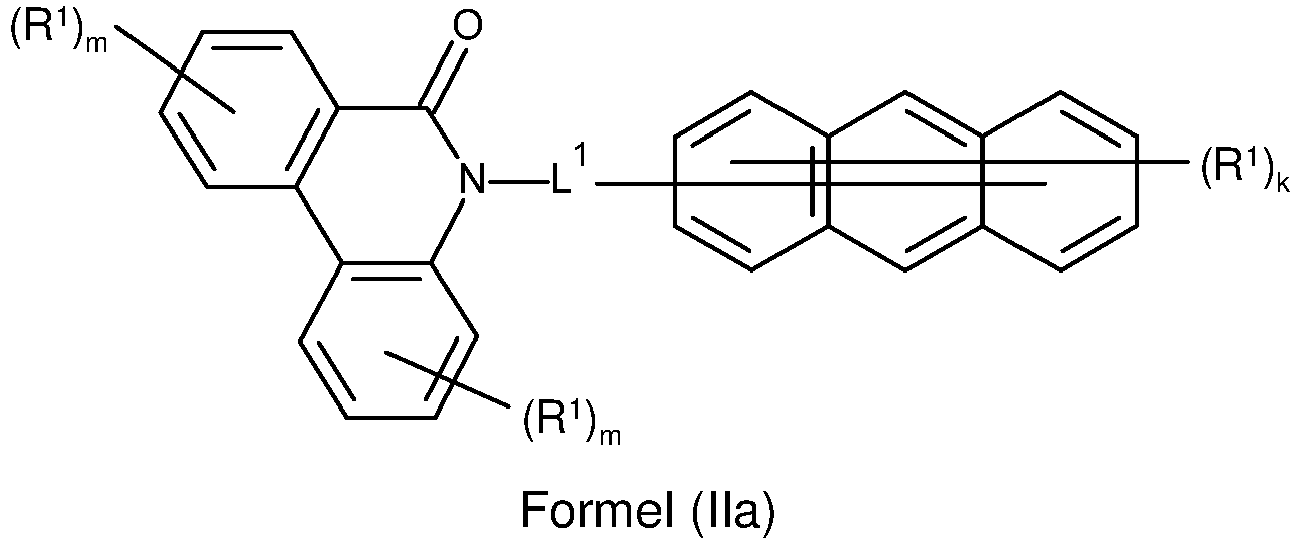


- Verbindung gemäß Anspruch 1 oder 7, dadurch gekennzeichnet, dass die Verbindung eine Struktur der Formel (IIa-1), (IIa-2) oder (IIa-3) aufweist:


- Zusammensetzung enthaltend wenigstens eine Verbindung nach einem oder mehreren der Ansprüche 1 bis 8 und wenigstens eine weitere Verbindung ausgewählt aus der Gruppe bestehend aus fluoreszierenden Emittern, phosphoreszierenden Emittern, Host Materialien, Matrix-Materialien, Elektronentransportmaterialien, Elektroneninjektionsmaterialien, Lochleitermaterialien, Lochinjektionsmaterialien, Elektronenblockiermaterialien und Lochblockiermaterialien.
- Formulierung enthaltend mindestens eine Verbindung nach einem oder mehreren der Ansprüche 1 bis 8 und/oder wenigstens eine Zusammensetzung nach Anspruch 9 und mindestens ein Lösungsmittel.
- Verfahren zur Herstellung einer Verbindung nach einem oder mehreren der Ansprüche 1 bis 8, dadurch gekennzeichnet, dass in einer Kupplungsreaktion eine Verbindung mit drei anellierten aromatischen Ringen mit einer Verbindung, umfassend mindestens ein Strukturelement mit einem aromatischen Valerolaktam, umgesetzt wird.
- Verwendung einer Verbindung nach einem oder mehreren der Ansprüche 1 bis 8 oder einer Zusammensetzung nach Anspruch 9 in einer elektronischen Vorrichtung als Elektronentransportmaterial, Elektroneninjektionsmaterial und/oder Lochblockiermaterial.
- Elektronische Vorrichtung, enthaltend mindestens eine Verbindung nach einem oder mehreren der Ansprüche 1 bis 8 oder eine Zusammensetzung gemäß Anspruch 9, wobei die elektronische Vorrichtung bevorzugt ausgewählt ist aus der Gruppe bestehend aus organischen Elektrolumineszenzvorrichtungen, organischen integrierten Schaltungen, organischen Feld-Effekt-Transistoren, organischen Dünnfilmtransistoren, organischen lichtemittierenden Transistoren, organischen Solarzellen, organischen optischen Detektoren, organischen Photorezeptoren, organischen Feld-Quench-Devices, lichtemittierenden elektrochemischen Zellen oder organischen Laserdioden.
Applications Claiming Priority (2)
| Application Number | Priority Date | Filing Date | Title |
|---|---|---|---|
| EP16201334 | 2016-11-30 | ||
| PCT/EP2017/080485 WO2018099846A1 (de) | 2016-11-30 | 2017-11-27 | Verbindungen mit valerolaktam-strukturen |
Publications (2)
| Publication Number | Publication Date |
|---|---|
| EP3548467A1 EP3548467A1 (de) | 2019-10-09 |
| EP3548467B1 true EP3548467B1 (de) | 2023-06-21 |
Family
ID=57471669
Family Applications (1)
| Application Number | Title | Priority Date | Filing Date |
|---|---|---|---|
| EP17811242.1A Active EP3548467B1 (de) | 2016-11-30 | 2017-11-27 | Verbindungen mit valerolaktam-strukturen |
Country Status (7)
| Country | Link |
|---|---|
| US (1) | US11713319B2 (de) |
| EP (1) | EP3548467B1 (de) |
| JP (1) | JP7127026B2 (de) |
| KR (1) | KR102539246B1 (de) |
| CN (1) | CN109996788B (de) |
| TW (1) | TW201829385A (de) |
| WO (1) | WO2018099846A1 (de) |
Families Citing this family (10)
| Publication number | Priority date | Publication date | Assignee | Title |
|---|---|---|---|---|
| US20220069231A1 (en) * | 2018-07-20 | 2022-03-03 | Merck Patent Gmbh | Materials for organic electroluminescent devices |
| KR20210097741A (ko) | 2018-11-30 | 2021-08-09 | 메르크 파텐트 게엠베하 | 전자 디바이스용 화합물 |
| CN110627834A (zh) * | 2019-10-23 | 2019-12-31 | 苏州久显新材料有限公司 | 磷杂菲啶酮衍生物及其合成方法和含有磷杂菲啶酮衍生物的电子器件 |
| CN110698430A (zh) * | 2019-10-23 | 2020-01-17 | 苏州久显新材料有限公司 | 硫杂菲啶酮衍生物及其合成方法和含有硫杂菲啶酮衍生物的电子器件 |
| CN110698400A (zh) * | 2019-10-23 | 2020-01-17 | 苏州久显新材料有限公司 | 菲啶酮衍生物及其合成方法和含有菲啶酮衍生物的电子器件 |
| WO2021191058A1 (en) * | 2020-03-23 | 2021-09-30 | Merck Patent Gmbh | Materials for organic electroluminescent devices |
| CN114560809B (zh) * | 2022-03-07 | 2024-04-19 | 武汉天马微电子有限公司 | 一种有机化合物及其应用 |
| CN114634511B (zh) * | 2022-03-22 | 2023-10-31 | 武汉天马微电子有限公司 | 一种有机化合物及其应用 |
| CN117362292B (zh) * | 2023-06-15 | 2025-07-22 | 闽都创新实验室 | 酰胺衍生物热活化延迟荧光材料及其制备方法和应用 |
| CN116924986B (zh) * | 2023-09-18 | 2024-04-09 | 山东千铄新材料有限公司 | 一种含氮杂环的功能层材料、制备方法及应用 |
Family Cites Families (103)
| Publication number | Priority date | Publication date | Assignee | Title |
|---|---|---|---|---|
| US4539507A (en) | 1983-03-25 | 1985-09-03 | Eastman Kodak Company | Organic electroluminescent devices having improved power conversion efficiencies |
| DE4111878A1 (de) | 1991-04-11 | 1992-10-15 | Wacker Chemie Gmbh | Leiterpolymere mit konjugierten doppelbindungen |
| US5151629A (en) | 1991-08-01 | 1992-09-29 | Eastman Kodak Company | Blue emitting internal junction organic electroluminescent device (I) |
| JPH07133483A (ja) | 1993-11-09 | 1995-05-23 | Shinko Electric Ind Co Ltd | El素子用有機発光材料及びel素子 |
| EP0676461B1 (de) | 1994-04-07 | 2002-08-14 | Covion Organic Semiconductors GmbH | Spiroverbindungen und ihre Verwendung als Elektrolumineszenzmaterialien |
| DE4436773A1 (de) | 1994-10-14 | 1996-04-18 | Hoechst Ag | Konjugierte Polymere mit Spirozentren und ihre Verwendung als Elektrolumineszenzmaterialien |
| JP3865406B2 (ja) | 1995-07-28 | 2007-01-10 | 住友化学株式会社 | 2,7−アリール−9−置換フルオレン及び9−置換フルオレンオリゴマー及びポリマー |
| DE19614971A1 (de) | 1996-04-17 | 1997-10-23 | Hoechst Ag | Polymere mit Spiroatomen und ihre Verwendung als Elektrolumineszenzmaterialien |
| DE19652261A1 (de) | 1996-12-16 | 1998-06-18 | Hoechst Ag | Arylsubstituierte Poly(p-arylenvinylene), Verfahren zur Herstellung und deren Verwendung in Elektroluminszenzbauelementen |
| DE19846766A1 (de) | 1998-10-10 | 2000-04-20 | Aventis Res & Tech Gmbh & Co | Konjugierte Polymere, enthaltend spezielle Fluorenbausteine mit verbesserten Eigenschaften |
| US6166172A (en) | 1999-02-10 | 2000-12-26 | Carnegie Mellon University | Method of forming poly-(3-substituted) thiophenes |
| KR100913568B1 (ko) | 1999-05-13 | 2009-08-26 | 더 트러스티즈 오브 프린스턴 유니버시티 | 전계인광에 기초한 고 효율의 유기 발광장치 |
| US6660901B2 (en) * | 1999-09-24 | 2003-12-09 | Glenda Church | Charcoal skin patch |
| WO2001041512A1 (en) | 1999-12-01 | 2001-06-07 | The Trustees Of Princeton University | Complexes of form l2mx as phosphorescent dopants for organic leds |
| DE19961338A1 (de) * | 1999-12-17 | 2001-06-21 | Nutrinova Gmbh | Feste Mischung von Lebensmittelinhalts- und Lebensmittelzusatzstoffen, Verfahren zu ihrer Herstellung und Verwendung derselben |
| TW532048B (en) | 2000-03-27 | 2003-05-11 | Idemitsu Kosan Co | Organic electroluminescence element |
| US20020121638A1 (en) | 2000-06-30 | 2002-09-05 | Vladimir Grushin | Electroluminescent iridium compounds with fluorinated phenylpyridines, phenylpyrimidines, and phenylquinolines and devices made with such compounds |
| CN101924190B (zh) | 2000-08-11 | 2012-07-04 | 普林斯顿大学理事会 | 有机金属化合物和发射转换有机电致磷光 |
| JP4154139B2 (ja) | 2000-09-26 | 2008-09-24 | キヤノン株式会社 | 発光素子 |
| JP4154140B2 (ja) | 2000-09-26 | 2008-09-24 | キヤノン株式会社 | 金属配位化合物 |
| JP4154138B2 (ja) | 2000-09-26 | 2008-09-24 | キヤノン株式会社 | 発光素子、表示装置及び金属配位化合物 |
| AU2002306698A1 (en) | 2001-03-14 | 2002-09-24 | The Trustees Of Princeton University | Materials and devices for blue phosphorescence based organic light emitting diodes |
| ITRM20020411A1 (it) | 2002-08-01 | 2004-02-02 | Univ Roma La Sapienza | Derivati dello spirobifluorene, loro preparazione e loro uso. |
| GB0226010D0 (en) | 2002-11-08 | 2002-12-18 | Cambridge Display Tech Ltd | Polymers for use in organic electroluminescent devices |
| DE10304819A1 (de) | 2003-02-06 | 2004-08-19 | Covion Organic Semiconductors Gmbh | Carbazol-enthaltende konjugierte Polymere und Blends, deren Darstellung und Verwendung |
| JP4411851B2 (ja) | 2003-03-19 | 2010-02-10 | コニカミノルタホールディングス株式会社 | 有機エレクトロルミネッセンス素子 |
| DE602004015432D1 (de) * | 2003-03-24 | 2008-09-11 | Novo Nordisk As | Transparentes elektronisches markieren eines medikamentenbehälters |
| US7345301B2 (en) | 2003-04-15 | 2008-03-18 | Merck Patent Gmbh | Mixtures of matrix materials and organic semiconductors capable of emission, use of the same and electronic components containing said mixtures |
| JP4635870B2 (ja) | 2003-04-23 | 2011-02-23 | コニカミノルタホールディングス株式会社 | 有機エレクトロルミネッセンス素子、照明装置及び表示装置 |
| EP1491568A1 (de) | 2003-06-23 | 2004-12-29 | Covion Organic Semiconductors GmbH | Halbleitende Polymere |
| DE10328627A1 (de) | 2003-06-26 | 2005-02-17 | Covion Organic Semiconductors Gmbh | Neue Materialien für die Elektrolumineszenz |
| DE10333232A1 (de) | 2003-07-21 | 2007-10-11 | Merck Patent Gmbh | Organisches Elektrolumineszenzelement |
| DE10337346A1 (de) | 2003-08-12 | 2005-03-31 | Covion Organic Semiconductors Gmbh | Konjugierte Polymere enthaltend Dihydrophenanthren-Einheiten und deren Verwendung |
| DE10338550A1 (de) | 2003-08-19 | 2005-03-31 | Basf Ag | Übergangsmetallkomplexe mit Carbenliganden als Emitter für organische Licht-emittierende Dioden (OLEDs) |
| DE10345572A1 (de) | 2003-09-29 | 2005-05-19 | Covion Organic Semiconductors Gmbh | Metallkomplexe |
| US7795801B2 (en) | 2003-09-30 | 2010-09-14 | Konica Minolta Holdings, Inc. | Organic electroluminescent element, illuminator, display and compound |
| EP2366752B1 (de) | 2003-10-22 | 2016-07-20 | Merck Patent GmbH | Neue materialien für die elektrolumineszenz und deren verwendung |
| WO2005053051A1 (de) | 2003-11-25 | 2005-06-09 | Merck Patent Gmbh | Organisches elektrolumineszenzelement |
| US7790890B2 (en) | 2004-03-31 | 2010-09-07 | Konica Minolta Holdings, Inc. | Organic electroluminescence element material, organic electroluminescence element, display device and illumination device |
| DE102004020298A1 (de) | 2004-04-26 | 2005-11-10 | Covion Organic Semiconductors Gmbh | Elektrolumineszierende Polymere und deren Verwendung |
| DE102004023277A1 (de) | 2004-05-11 | 2005-12-01 | Covion Organic Semiconductors Gmbh | Neue Materialmischungen für die Elektrolumineszenz |
| US7598388B2 (en) | 2004-05-18 | 2009-10-06 | The University Of Southern California | Carbene containing metal complexes as OLEDs |
| JP4862248B2 (ja) | 2004-06-04 | 2012-01-25 | コニカミノルタホールディングス株式会社 | 有機エレクトロルミネッセンス素子、照明装置及び表示装置 |
| ITRM20040352A1 (it) | 2004-07-15 | 2004-10-15 | Univ Roma La Sapienza | Derivati oligomerici dello spirobifluorene, loro preparazione e loro uso. |
| EP1669386A1 (de) | 2004-12-06 | 2006-06-14 | Covion Organic Semiconductors GmbH | Teilkonjugierte Polymere, deren Darstellung und Verwendung |
| WO2006117052A1 (de) | 2005-05-03 | 2006-11-09 | Merck Patent Gmbh | Organische elektrolumineszenzvorrichtung und in deren herstellung verwendete boronsäure- und borinsäure-derivate |
| DE102005037734B4 (de) | 2005-08-10 | 2018-02-08 | Merck Patent Gmbh | Elektrolumineszierende Polymere, ihre Verwendung und bifunktionelle monomere Verbindungen |
| EP1956022B1 (de) | 2005-12-01 | 2012-07-25 | Nippon Steel Chemical Co., Ltd. | Verbindung für organisches elektrolumineszentes element und organisches elektrolumineszentes element |
| DE102006025777A1 (de) | 2006-05-31 | 2007-12-06 | Merck Patent Gmbh | Neue Materialien für organische Elektrolumineszenzvorrichtungen |
| EP2080762B1 (de) | 2006-11-09 | 2016-09-14 | Nippon Steel & Sumikin Chemical Co., Ltd. | Verbindung für organische elektrolumineszenzvorrichtung und organische elektrolumineszenzvorrichtung |
| DK2101574T3 (en) * | 2006-11-29 | 2016-09-12 | Solenne Bv | COMPOUNDS AND FORMULAS SUITABLE FOR RADICAL COLLECTION |
| JP2010515255A (ja) | 2006-12-28 | 2010-05-06 | ユニバーサル ディスプレイ コーポレイション | 長寿命リン光発光有機発光デバイス(oled)構造 |
| DE102007002714A1 (de) | 2007-01-18 | 2008-07-31 | Merck Patent Gmbh | Neue Materialien für organische Elektrolumineszenzvorrichtungen |
| DE102007053771A1 (de) | 2007-11-12 | 2009-05-14 | Merck Patent Gmbh | Organische Elektrolumineszenzvorrichtungen |
| US7862908B2 (en) | 2007-11-26 | 2011-01-04 | National Tsing Hua University | Conjugated compounds containing hydroindoloacridine structural elements, and their use |
| WO2009140467A1 (en) * | 2008-05-15 | 2009-11-19 | Purdue Research Foundation | Oxobenzindolizinoquinolines and uses thereof |
| DE102008027005A1 (de) | 2008-06-05 | 2009-12-10 | Merck Patent Gmbh | Organische elektronische Vorrichtung enthaltend Metallkomplexe |
| DE102008033943A1 (de) | 2008-07-18 | 2010-01-21 | Merck Patent Gmbh | Neue Materialien für organische Elektrolumineszenzvorrichtungen |
| DE102008036247A1 (de) | 2008-08-04 | 2010-02-11 | Merck Patent Gmbh | Elektronische Vorrichtungen enthaltend Metallkomplexe |
| DE102008036982A1 (de) | 2008-08-08 | 2010-02-11 | Merck Patent Gmbh | Organische Elektrolumineszenzvorrichtung |
| DE102008048336A1 (de) | 2008-09-22 | 2010-03-25 | Merck Patent Gmbh | Einkernige neutrale Kupfer(I)-Komplexe und deren Verwendung zur Herstellung von optoelektronischen Bauelementen |
| EP2350053B1 (de) * | 2008-10-17 | 2013-12-11 | Whitehead Institute For Biomedical Research | Modulatoren von MTOR-Komplexen |
| KR101506919B1 (ko) | 2008-10-31 | 2015-03-30 | 롬엔드하스전자재료코리아유한회사 | 신규한 유기 전자재료용 화합물 및 이를 포함하는 유기 전자 소자 |
| DE102008056688A1 (de) | 2008-11-11 | 2010-05-12 | Merck Patent Gmbh | Materialien für organische Elektrolumineszenzvorrichtungen |
| JP5701766B2 (ja) | 2008-11-11 | 2015-04-15 | メルク パテント ゲーエムベーハー | 有機エレクトロルミネセント素子 |
| DE102008057050B4 (de) | 2008-11-13 | 2021-06-02 | Merck Patent Gmbh | Materialien für organische Elektrolumineszenzvorrichtungen |
| DE102008057051B4 (de) | 2008-11-13 | 2021-06-17 | Merck Patent Gmbh | Materialien für organische Elektrolumineszenzvorrichtungen |
| DE102009007038A1 (de) | 2009-02-02 | 2010-08-05 | Merck Patent Gmbh | Metallkomplexe |
| DE102009011223A1 (de) | 2009-03-02 | 2010-09-23 | Merck Patent Gmbh | Metallkomplexe |
| DE102009013041A1 (de) | 2009-03-13 | 2010-09-16 | Merck Patent Gmbh | Materialien für organische Elektrolumineszenzvorrichtungen |
| DE102009014513A1 (de) | 2009-03-23 | 2010-09-30 | Merck Patent Gmbh | Organische Elektrolumineszenzvorrichtung |
| JP5629980B2 (ja) | 2009-05-22 | 2014-11-26 | コニカミノルタ株式会社 | 有機エレクトロルミネッセンス素子、表示装置及び照明装置 |
| DE102009023155A1 (de) | 2009-05-29 | 2010-12-02 | Merck Patent Gmbh | Materialien für organische Elektrolumineszenzvorrichtungen |
| DE102009031021A1 (de) | 2009-06-30 | 2011-01-05 | Merck Patent Gmbh | Materialien für organische Elektrolumineszenzvorrichtungen |
| DE102009041414A1 (de) | 2009-09-16 | 2011-03-17 | Merck Patent Gmbh | Metallkomplexe |
| DE102009048791A1 (de) | 2009-10-08 | 2011-04-14 | Merck Patent Gmbh | Materialien für organische Elektrolumineszenzvorrichtungen |
| DE102009057167A1 (de) | 2009-12-05 | 2011-06-09 | Merck Patent Gmbh | Elektronische Vorrichtung enthaltend Metallkomplexe |
| DE102010005697A1 (de) | 2010-01-25 | 2011-07-28 | Merck Patent GmbH, 64293 | Verbindungen für elektronische Vorrichtungen |
| CN102812007A (zh) * | 2010-02-01 | 2012-12-05 | 国立大学法人鹿儿岛大学 | 用于丙型肝炎的治疗剂 |
| DE102010012738A1 (de) | 2010-03-25 | 2011-09-29 | Merck Patent Gmbh | Materialien für organische Elektrolumineszenzvorrichtungen |
| DE102010019306B4 (de) | 2010-05-04 | 2021-05-20 | Merck Patent Gmbh | Organische Elektrolumineszenzvorrichtungen |
| DE112011102008B4 (de) | 2010-06-15 | 2022-04-21 | Merck Patent Gmbh | Metallkomplexe |
| DE102010027317A1 (de) | 2010-07-16 | 2012-01-19 | Merck Patent Gmbh | Metallkomplexe |
| DE102010048608A1 (de) | 2010-10-15 | 2012-04-19 | Merck Patent Gmbh | Materialien für organische Elektrolumineszenzvorrichtungen |
| KR101979469B1 (ko) | 2011-04-18 | 2019-05-16 | 메르크 파텐트 게엠베하 | 유기 전계발광 소자용 재료 |
| WO2013064206A1 (de) | 2011-11-01 | 2013-05-10 | Merck Patent Gmbh | Organische elektrolumineszenzvorrichtung |
| WO2014008982A1 (de) | 2012-07-13 | 2014-01-16 | Merck Patent Gmbh | Metallkomplexe |
| CN104603111A (zh) | 2012-07-23 | 2015-05-06 | 默克专利有限公司 | 芴和含有所述芴的电子器件 |
| US11917901B2 (en) | 2012-08-07 | 2024-02-27 | Udc Ireland Limited | Metal complexes |
| WO2014056567A1 (de) * | 2012-10-11 | 2014-04-17 | Merck Patent Gmbh | Materialien für organische elektrolumineszenzvorrichtungen |
| KR102188212B1 (ko) | 2012-12-21 | 2020-12-08 | 메르크 파텐트 게엠베하 | 금속 착물 |
| KR102188214B1 (ko) | 2012-12-21 | 2020-12-08 | 메르크 파텐트 게엠베하 | 금속 착물 |
| EP2935276B1 (de) | 2012-12-21 | 2017-11-01 | Merck Patent GmbH | Materialien für organische elektrolumineszenzvorrichtungen |
| CN105531347B (zh) | 2013-09-11 | 2018-09-11 | 默克专利有限公司 | 金属络合物 |
| WO2015065338A1 (en) | 2013-10-29 | 2015-05-07 | Medivir Ab | Quinazoline based respiratory syncytial virus inhibitors |
| US11005050B2 (en) | 2014-01-13 | 2021-05-11 | Merck Patent Gmbh | Metal complexes |
| CN105980519B (zh) | 2014-02-05 | 2019-06-14 | 默克专利有限公司 | 金属络合物 |
| EP3140302B1 (de) | 2014-05-05 | 2019-08-21 | Merck Patent GmbH | Materialien für organische elektrolumineszenzvorrichtungen |
| CN106488917B (zh) | 2014-06-18 | 2020-05-05 | 默克专利有限公司 | 用于有机电致发光器件的材料 |
| JP6707517B2 (ja) | 2014-07-28 | 2020-06-10 | メルク、パテント、ゲゼルシャフト、ミット、ベシュレンクテル、ハフツングMerck Patent GmbH | 金属錯体 |
| WO2016015810A1 (de) | 2014-07-29 | 2016-02-04 | Merck Patent Gmbh | Materialien f?r organische elektrolumineszenzvorrichtungen |
| CN106661007B (zh) | 2014-08-13 | 2019-08-13 | 默克专利有限公司 | 用于有机电致发光器件的材料 |
| WO2016124304A1 (de) | 2015-02-03 | 2016-08-11 | Merck Patent Gmbh | Metallkomplexe |
-
2017
- 2017-11-27 KR KR1020197018546A patent/KR102539246B1/ko active Active
- 2017-11-27 WO PCT/EP2017/080485 patent/WO2018099846A1/de not_active Ceased
- 2017-11-27 CN CN201780072471.5A patent/CN109996788B/zh active Active
- 2017-11-27 US US16/465,462 patent/US11713319B2/en active Active
- 2017-11-27 EP EP17811242.1A patent/EP3548467B1/de active Active
- 2017-11-27 TW TW106141139A patent/TW201829385A/zh unknown
- 2017-11-27 JP JP2019528874A patent/JP7127026B2/ja active Active
Also Published As
| Publication number | Publication date |
|---|---|
| CN109996788B (zh) | 2023-11-17 |
| US20200031827A1 (en) | 2020-01-30 |
| US11713319B2 (en) | 2023-08-01 |
| KR20190086754A (ko) | 2019-07-23 |
| KR102539246B1 (ko) | 2023-06-01 |
| JP7127026B2 (ja) | 2022-08-29 |
| TW201829385A (zh) | 2018-08-16 |
| EP3548467A1 (de) | 2019-10-09 |
| JP2020500865A (ja) | 2020-01-16 |
| WO2018099846A1 (de) | 2018-06-07 |
| CN109996788A (zh) | 2019-07-09 |
Similar Documents
| Publication | Publication Date | Title |
|---|---|---|
| EP3519415B1 (de) | Carbazole mit diazadibenzofuran- oder diazadibenzothiophen-strukturen | |
| EP3519417B1 (de) | Verbindungen mit diazadibenzofuran- oder diazadibenzothiophen-strukturen | |
| EP3237387B1 (de) | Heterocyclische verbindungen mit dibenzazapin-strukturen | |
| EP3708634B1 (de) | Heterocyclische spiroverbindungen | |
| EP3221294B1 (de) | Heterocyclische verbindungen zur verwendung in elektronischen vorrichtungen | |
| EP3237409B1 (de) | Carbazole mit zwei dibenzofuran- oder dibenzothiophensubstituenten | |
| EP3596065B1 (de) | Verbindungen mit arylamin-strukturen | |
| EP3328850B1 (de) | Verbindungen mit fluoren-strukturen | |
| EP3430006A1 (de) | Verbindungen mit spirobifluoren-strukturen | |
| EP4190880B1 (de) | Verbindungen, die in einer organischen elektronischen vorrichtung als aktive verbindungen einsetzbar sind | |
| EP3526228A1 (de) | Metallkomplexe | |
| WO2018099846A1 (de) | Verbindungen mit valerolaktam-strukturen | |
| WO2018138039A1 (de) | Carbazolderivate | |
| WO2018050583A1 (de) | Verbindungen mit carbazol-strukturen | |
| WO2022079068A1 (de) | Heterocyclische verbindungen für organische elektrolumineszenzvorrichtungen | |
| EP3197887B1 (de) | Heterocyclische verbindungen mit benzo[c]coumarin-strukturen | |
| EP3978491B1 (de) | Stickstoffhaltige heterocyclen zur verwendung in oleds | |
| EP3512841B1 (de) | Verbindungen mit spirobifluoren-strukturen | |
| EP3548481B1 (de) | Heterocyclische verbindungen zur verwendung in elektronischen vorrichtungen |
Legal Events
| Date | Code | Title | Description |
|---|---|---|---|
| STAA | Information on the status of an ep patent application or granted ep patent |
Free format text: STATUS: UNKNOWN |
|
| STAA | Information on the status of an ep patent application or granted ep patent |
Free format text: STATUS: THE INTERNATIONAL PUBLICATION HAS BEEN MADE |
|
| PUAI | Public reference made under article 153(3) epc to a published international application that has entered the european phase |
Free format text: ORIGINAL CODE: 0009012 |
|
| STAA | Information on the status of an ep patent application or granted ep patent |
Free format text: STATUS: REQUEST FOR EXAMINATION WAS MADE |
|
| 17P | Request for examination filed |
Effective date: 20190527 |
|
| AK | Designated contracting states |
Kind code of ref document: A1 Designated state(s): AL AT BE BG CH CY CZ DE DK EE ES FI FR GB GR HR HU IE IS IT LI LT LU LV MC MK MT NL NO PL PT RO RS SE SI SK SM TR |
|
| AX | Request for extension of the european patent |
Extension state: BA ME |
|
| RIN1 | Information on inventor provided before grant (corrected) |
Inventor name: PARHAM, AMIR Inventor name: JATSCH, ANJA Inventor name: LINGE, ROUVEN Inventor name: GROSSMANN, TOBIAS |
|
| DAV | Request for validation of the european patent (deleted) | ||
| DAX | Request for extension of the european patent (deleted) | ||
| STAA | Information on the status of an ep patent application or granted ep patent |
Free format text: STATUS: EXAMINATION IS IN PROGRESS |
|
| 17Q | First examination report despatched |
Effective date: 20201106 |
|
| RAP3 | Party data changed (applicant data changed or rights of an application transferred) |
Owner name: MERCK PATENT GMBH |
|
| GRAP | Despatch of communication of intention to grant a patent |
Free format text: ORIGINAL CODE: EPIDOSNIGR1 |
|
| STAA | Information on the status of an ep patent application or granted ep patent |
Free format text: STATUS: GRANT OF PATENT IS INTENDED |
|
| INTG | Intention to grant announced |
Effective date: 20230120 |
|
| GRAS | Grant fee paid |
Free format text: ORIGINAL CODE: EPIDOSNIGR3 |
|
| GRAA | (expected) grant |
Free format text: ORIGINAL CODE: 0009210 |
|
| STAA | Information on the status of an ep patent application or granted ep patent |
Free format text: STATUS: THE PATENT HAS BEEN GRANTED |
|
| AK | Designated contracting states |
Kind code of ref document: B1 Designated state(s): AL AT BE BG CH CY CZ DE DK EE ES FI FR GB GR HR HU IE IS IT LI LT LU LV MC MK MT NL NO PL PT RO RS SE SI SK SM TR |
|
| P01 | Opt-out of the competence of the unified patent court (upc) registered |
Effective date: 20230519 |
|
| REG | Reference to a national code |
Ref country code: CH Ref legal event code: EP |
|
| REG | Reference to a national code |
Ref country code: DE Ref legal event code: R096 Ref document number: 502017014959 Country of ref document: DE |
|
| REG | Reference to a national code |
Ref country code: AT Ref legal event code: REF Ref document number: 1580826 Country of ref document: AT Kind code of ref document: T Effective date: 20230715 |
|
| REG | Reference to a national code |
Ref country code: IE Ref legal event code: FG4D Free format text: LANGUAGE OF EP DOCUMENT: GERMAN |
|
| REG | Reference to a national code |
Ref country code: LT Ref legal event code: MG9D |
|
| REG | Reference to a national code |
Ref country code: NL Ref legal event code: MP Effective date: 20230621 |
|
| PG25 | Lapsed in a contracting state [announced via postgrant information from national office to epo] |
Ref country code: SE Free format text: LAPSE BECAUSE OF FAILURE TO SUBMIT A TRANSLATION OF THE DESCRIPTION OR TO PAY THE FEE WITHIN THE PRESCRIBED TIME-LIMIT Effective date: 20230621 Ref country code: NO Free format text: LAPSE BECAUSE OF FAILURE TO SUBMIT A TRANSLATION OF THE DESCRIPTION OR TO PAY THE FEE WITHIN THE PRESCRIBED TIME-LIMIT Effective date: 20230921 |
|
| PG25 | Lapsed in a contracting state [announced via postgrant information from national office to epo] |
Ref country code: RS Free format text: LAPSE BECAUSE OF FAILURE TO SUBMIT A TRANSLATION OF THE DESCRIPTION OR TO PAY THE FEE WITHIN THE PRESCRIBED TIME-LIMIT Effective date: 20230621 Ref country code: NL Free format text: LAPSE BECAUSE OF FAILURE TO SUBMIT A TRANSLATION OF THE DESCRIPTION OR TO PAY THE FEE WITHIN THE PRESCRIBED TIME-LIMIT Effective date: 20230621 Ref country code: LV Free format text: LAPSE BECAUSE OF FAILURE TO SUBMIT A TRANSLATION OF THE DESCRIPTION OR TO PAY THE FEE WITHIN THE PRESCRIBED TIME-LIMIT Effective date: 20230621 Ref country code: LT Free format text: LAPSE BECAUSE OF FAILURE TO SUBMIT A TRANSLATION OF THE DESCRIPTION OR TO PAY THE FEE WITHIN THE PRESCRIBED TIME-LIMIT Effective date: 20230621 Ref country code: HR Free format text: LAPSE BECAUSE OF FAILURE TO SUBMIT A TRANSLATION OF THE DESCRIPTION OR TO PAY THE FEE WITHIN THE PRESCRIBED TIME-LIMIT Effective date: 20230621 Ref country code: GR Free format text: LAPSE BECAUSE OF FAILURE TO SUBMIT A TRANSLATION OF THE DESCRIPTION OR TO PAY THE FEE WITHIN THE PRESCRIBED TIME-LIMIT Effective date: 20230922 |
|
| PG25 | Lapsed in a contracting state [announced via postgrant information from national office to epo] |
Ref country code: FI Free format text: LAPSE BECAUSE OF FAILURE TO SUBMIT A TRANSLATION OF THE DESCRIPTION OR TO PAY THE FEE WITHIN THE PRESCRIBED TIME-LIMIT Effective date: 20230621 |
|
| PG25 | Lapsed in a contracting state [announced via postgrant information from national office to epo] |
Ref country code: SK Free format text: LAPSE BECAUSE OF FAILURE TO SUBMIT A TRANSLATION OF THE DESCRIPTION OR TO PAY THE FEE WITHIN THE PRESCRIBED TIME-LIMIT Effective date: 20230621 |
|
| PG25 | Lapsed in a contracting state [announced via postgrant information from national office to epo] |
Ref country code: ES Free format text: LAPSE BECAUSE OF FAILURE TO SUBMIT A TRANSLATION OF THE DESCRIPTION OR TO PAY THE FEE WITHIN THE PRESCRIBED TIME-LIMIT Effective date: 20230621 |
|
| PG25 | Lapsed in a contracting state [announced via postgrant information from national office to epo] |
Ref country code: IS Free format text: LAPSE BECAUSE OF FAILURE TO SUBMIT A TRANSLATION OF THE DESCRIPTION OR TO PAY THE FEE WITHIN THE PRESCRIBED TIME-LIMIT Effective date: 20231021 |
|
| PG25 | Lapsed in a contracting state [announced via postgrant information from national office to epo] |
Ref country code: SM Free format text: LAPSE BECAUSE OF FAILURE TO SUBMIT A TRANSLATION OF THE DESCRIPTION OR TO PAY THE FEE WITHIN THE PRESCRIBED TIME-LIMIT Effective date: 20230621 Ref country code: SK Free format text: LAPSE BECAUSE OF FAILURE TO SUBMIT A TRANSLATION OF THE DESCRIPTION OR TO PAY THE FEE WITHIN THE PRESCRIBED TIME-LIMIT Effective date: 20230621 Ref country code: RO Free format text: LAPSE BECAUSE OF FAILURE TO SUBMIT A TRANSLATION OF THE DESCRIPTION OR TO PAY THE FEE WITHIN THE PRESCRIBED TIME-LIMIT Effective date: 20230621 Ref country code: PT Free format text: LAPSE BECAUSE OF FAILURE TO SUBMIT A TRANSLATION OF THE DESCRIPTION OR TO PAY THE FEE WITHIN THE PRESCRIBED TIME-LIMIT Effective date: 20231023 Ref country code: IS Free format text: LAPSE BECAUSE OF FAILURE TO SUBMIT A TRANSLATION OF THE DESCRIPTION OR TO PAY THE FEE WITHIN THE PRESCRIBED TIME-LIMIT Effective date: 20231021 Ref country code: ES Free format text: LAPSE BECAUSE OF FAILURE TO SUBMIT A TRANSLATION OF THE DESCRIPTION OR TO PAY THE FEE WITHIN THE PRESCRIBED TIME-LIMIT Effective date: 20230621 Ref country code: EE Free format text: LAPSE BECAUSE OF FAILURE TO SUBMIT A TRANSLATION OF THE DESCRIPTION OR TO PAY THE FEE WITHIN THE PRESCRIBED TIME-LIMIT Effective date: 20230621 Ref country code: CZ Free format text: LAPSE BECAUSE OF FAILURE TO SUBMIT A TRANSLATION OF THE DESCRIPTION OR TO PAY THE FEE WITHIN THE PRESCRIBED TIME-LIMIT Effective date: 20230621 |
|
| PG25 | Lapsed in a contracting state [announced via postgrant information from national office to epo] |
Ref country code: PL Free format text: LAPSE BECAUSE OF FAILURE TO SUBMIT A TRANSLATION OF THE DESCRIPTION OR TO PAY THE FEE WITHIN THE PRESCRIBED TIME-LIMIT Effective date: 20230621 |
|
| REG | Reference to a national code |
Ref country code: DE Ref legal event code: R097 Ref document number: 502017014959 Country of ref document: DE |
|
| PLBE | No opposition filed within time limit |
Free format text: ORIGINAL CODE: 0009261 |
|
| STAA | Information on the status of an ep patent application or granted ep patent |
Free format text: STATUS: NO OPPOSITION FILED WITHIN TIME LIMIT |
|
| PG25 | Lapsed in a contracting state [announced via postgrant information from national office to epo] |
Ref country code: DK Free format text: LAPSE BECAUSE OF FAILURE TO SUBMIT A TRANSLATION OF THE DESCRIPTION OR TO PAY THE FEE WITHIN THE PRESCRIBED TIME-LIMIT Effective date: 20230621 |
|
| PG25 | Lapsed in a contracting state [announced via postgrant information from national office to epo] |
Ref country code: SI Free format text: LAPSE BECAUSE OF FAILURE TO SUBMIT A TRANSLATION OF THE DESCRIPTION OR TO PAY THE FEE WITHIN THE PRESCRIBED TIME-LIMIT Effective date: 20230621 |
|
| 26N | No opposition filed |
Effective date: 20240322 |
|
| PG25 | Lapsed in a contracting state [announced via postgrant information from national office to epo] |
Ref country code: SI Free format text: LAPSE BECAUSE OF FAILURE TO SUBMIT A TRANSLATION OF THE DESCRIPTION OR TO PAY THE FEE WITHIN THE PRESCRIBED TIME-LIMIT Effective date: 20230621 Ref country code: IT Free format text: LAPSE BECAUSE OF FAILURE TO SUBMIT A TRANSLATION OF THE DESCRIPTION OR TO PAY THE FEE WITHIN THE PRESCRIBED TIME-LIMIT Effective date: 20230621 |
|
| REG | Reference to a national code |
Ref country code: CH Ref legal event code: PL |
|
| PG25 | Lapsed in a contracting state [announced via postgrant information from national office to epo] |
Ref country code: MC Free format text: LAPSE BECAUSE OF FAILURE TO SUBMIT A TRANSLATION OF THE DESCRIPTION OR TO PAY THE FEE WITHIN THE PRESCRIBED TIME-LIMIT Effective date: 20230621 |
|
| PG25 | Lapsed in a contracting state [announced via postgrant information from national office to epo] |
Ref country code: LU Free format text: LAPSE BECAUSE OF NON-PAYMENT OF DUE FEES Effective date: 20231127 |
|
| PG25 | Lapsed in a contracting state [announced via postgrant information from national office to epo] |
Ref country code: CH Free format text: LAPSE BECAUSE OF NON-PAYMENT OF DUE FEES Effective date: 20231130 |
|
| GBPC | Gb: european patent ceased through non-payment of renewal fee |
Effective date: 20231127 |
|
| PG25 | Lapsed in a contracting state [announced via postgrant information from national office to epo] |
Ref country code: MC Free format text: LAPSE BECAUSE OF FAILURE TO SUBMIT A TRANSLATION OF THE DESCRIPTION OR TO PAY THE FEE WITHIN THE PRESCRIBED TIME-LIMIT Effective date: 20230621 Ref country code: LU Free format text: LAPSE BECAUSE OF NON-PAYMENT OF DUE FEES Effective date: 20231127 Ref country code: CH Free format text: LAPSE BECAUSE OF NON-PAYMENT OF DUE FEES Effective date: 20231130 |
|
| REG | Reference to a national code |
Ref country code: BE Ref legal event code: MM Effective date: 20231130 |
|
| REG | Reference to a national code |
Ref country code: IE Ref legal event code: MM4A |
|
| PG25 | Lapsed in a contracting state [announced via postgrant information from national office to epo] |
Ref country code: IE Free format text: LAPSE BECAUSE OF NON-PAYMENT OF DUE FEES Effective date: 20231127 |
|
| PG25 | Lapsed in a contracting state [announced via postgrant information from national office to epo] |
Ref country code: GB Free format text: LAPSE BECAUSE OF NON-PAYMENT OF DUE FEES Effective date: 20231127 |
|
| PG25 | Lapsed in a contracting state [announced via postgrant information from national office to epo] |
Ref country code: BE Free format text: LAPSE BECAUSE OF NON-PAYMENT OF DUE FEES Effective date: 20231130 |
|
| PG25 | Lapsed in a contracting state [announced via postgrant information from national office to epo] |
Ref country code: FR Free format text: LAPSE BECAUSE OF NON-PAYMENT OF DUE FEES Effective date: 20231130 |
|
| PG25 | Lapsed in a contracting state [announced via postgrant information from national office to epo] |
Ref country code: IE Free format text: LAPSE BECAUSE OF NON-PAYMENT OF DUE FEES Effective date: 20231127 Ref country code: GB Free format text: LAPSE BECAUSE OF NON-PAYMENT OF DUE FEES Effective date: 20231127 Ref country code: FR Free format text: LAPSE BECAUSE OF NON-PAYMENT OF DUE FEES Effective date: 20231130 Ref country code: BE Free format text: LAPSE BECAUSE OF NON-PAYMENT OF DUE FEES Effective date: 20231130 |
|
| PG25 | Lapsed in a contracting state [announced via postgrant information from national office to epo] |
Ref country code: BG Free format text: LAPSE BECAUSE OF FAILURE TO SUBMIT A TRANSLATION OF THE DESCRIPTION OR TO PAY THE FEE WITHIN THE PRESCRIBED TIME-LIMIT Effective date: 20230621 |
|
| PG25 | Lapsed in a contracting state [announced via postgrant information from national office to epo] |
Ref country code: BG Free format text: LAPSE BECAUSE OF FAILURE TO SUBMIT A TRANSLATION OF THE DESCRIPTION OR TO PAY THE FEE WITHIN THE PRESCRIBED TIME-LIMIT Effective date: 20230621 |
|
| REG | Reference to a national code |
Ref country code: AT Ref legal event code: MM01 Ref document number: 1580826 Country of ref document: AT Kind code of ref document: T Effective date: 20231127 |
|
| PG25 | Lapsed in a contracting state [announced via postgrant information from national office to epo] |
Ref country code: AT Free format text: LAPSE BECAUSE OF NON-PAYMENT OF DUE FEES Effective date: 20231127 |
|
| PG25 | Lapsed in a contracting state [announced via postgrant information from national office to epo] |
Ref country code: AT Free format text: LAPSE BECAUSE OF NON-PAYMENT OF DUE FEES Effective date: 20231127 |
|
| PG25 | Lapsed in a contracting state [announced via postgrant information from national office to epo] |
Ref country code: CY Free format text: LAPSE BECAUSE OF FAILURE TO SUBMIT A TRANSLATION OF THE DESCRIPTION OR TO PAY THE FEE WITHIN THE PRESCRIBED TIME-LIMIT; INVALID AB INITIO Effective date: 20171127 |
|
| PG25 | Lapsed in a contracting state [announced via postgrant information from national office to epo] |
Ref country code: HU Free format text: LAPSE BECAUSE OF FAILURE TO SUBMIT A TRANSLATION OF THE DESCRIPTION OR TO PAY THE FEE WITHIN THE PRESCRIBED TIME-LIMIT; INVALID AB INITIO Effective date: 20171127 |
|
| PG25 | Lapsed in a contracting state [announced via postgrant information from national office to epo] |
Ref country code: TR Free format text: LAPSE BECAUSE OF FAILURE TO SUBMIT A TRANSLATION OF THE DESCRIPTION OR TO PAY THE FEE WITHIN THE PRESCRIBED TIME-LIMIT Effective date: 20230621 |
|
| PGFP | Annual fee paid to national office [announced via postgrant information from national office to epo] |
Ref country code: DE Payment date: 20251022 Year of fee payment: 9 |