EP2623367B1 - Vehicle seat and stiffness setting method for vehicle seat - Google Patents
Vehicle seat and stiffness setting method for vehicle seat Download PDFInfo
- Publication number
- EP2623367B1 EP2623367B1 EP11829360.4A EP11829360A EP2623367B1 EP 2623367 B1 EP2623367 B1 EP 2623367B1 EP 11829360 A EP11829360 A EP 11829360A EP 2623367 B1 EP2623367 B1 EP 2623367B1
- Authority
- EP
- European Patent Office
- Prior art keywords
- occupant
- seat
- vehicle seat
- seat cushion
- psc
- Prior art date
- Legal status (The legal status is an assumption and is not a legal conclusion. Google has not performed a legal analysis and makes no representation as to the accuracy of the status listed.)
- Active
Links
- 238000000034 method Methods 0.000 title claims description 19
- 210000001624 hip Anatomy 0.000 claims description 173
- 239000000463 material Substances 0.000 claims description 149
- 210000003127 knee Anatomy 0.000 claims description 79
- 210000000689 upper leg Anatomy 0.000 claims description 67
- 238000009826 distribution Methods 0.000 claims description 56
- 210000004197 pelvis Anatomy 0.000 claims description 54
- 210000002414 leg Anatomy 0.000 claims description 39
- 239000002344 surface layer Substances 0.000 claims description 25
- 230000007246 mechanism Effects 0.000 claims description 24
- 238000005452 bending Methods 0.000 claims description 15
- 230000004044 response Effects 0.000 claims description 10
- 230000006870 function Effects 0.000 description 111
- 210000000038 chest Anatomy 0.000 description 50
- 230000009471 action Effects 0.000 description 36
- 230000000694 effects Effects 0.000 description 35
- JOYRKODLDBILNP-UHFFFAOYSA-N Ethyl urethane Chemical compound CCOC(N)=O JOYRKODLDBILNP-UHFFFAOYSA-N 0.000 description 24
- 230000002265 prevention Effects 0.000 description 23
- 239000010410 layer Substances 0.000 description 22
- 230000008859 change Effects 0.000 description 17
- 239000002184 metal Substances 0.000 description 13
- 210000001503 joint Anatomy 0.000 description 11
- 238000003825 pressing Methods 0.000 description 10
- 230000001603 reducing effect Effects 0.000 description 10
- 210000000115 thoracic cavity Anatomy 0.000 description 10
- 230000005484 gravity Effects 0.000 description 7
- 210000002683 foot Anatomy 0.000 description 6
- 239000006260 foam Substances 0.000 description 5
- 230000006872 improvement Effects 0.000 description 5
- 210000002239 ischium bone Anatomy 0.000 description 5
- 230000009467 reduction Effects 0.000 description 5
- 238000013461 design Methods 0.000 description 4
- 210000003205 muscle Anatomy 0.000 description 4
- 230000008569 process Effects 0.000 description 4
- 229920003002 synthetic resin Polymers 0.000 description 4
- 239000000057 synthetic resin Substances 0.000 description 4
- 239000013013 elastic material Substances 0.000 description 3
- 239000004744 fabric Substances 0.000 description 3
- 210000000629 knee joint Anatomy 0.000 description 3
- 238000010586 diagram Methods 0.000 description 2
- 230000005489 elastic deformation Effects 0.000 description 2
- 238000005187 foaming Methods 0.000 description 2
- 238000007542 hardness measurement Methods 0.000 description 2
- 210000004394 hip joint Anatomy 0.000 description 2
- 239000010985 leather Substances 0.000 description 2
- 239000002649 leather substitute Substances 0.000 description 2
- 230000000149 penetrating effect Effects 0.000 description 2
- 229920005989 resin Polymers 0.000 description 2
- 239000011347 resin Substances 0.000 description 2
- 238000007665 sagging Methods 0.000 description 2
- 239000011800 void material Substances 0.000 description 2
- 229920005830 Polyurethane Foam Polymers 0.000 description 1
- 230000004075 alteration Effects 0.000 description 1
- 230000008901 benefit Effects 0.000 description 1
- 210000000988 bone and bone Anatomy 0.000 description 1
- 230000003247 decreasing effect Effects 0.000 description 1
- 230000001419 dependent effect Effects 0.000 description 1
- 210000000527 greater trochanter Anatomy 0.000 description 1
- 239000011796 hollow space material Substances 0.000 description 1
- 238000003780 insertion Methods 0.000 description 1
- 230000037431 insertion Effects 0.000 description 1
- 238000004519 manufacturing process Methods 0.000 description 1
- 239000007769 metal material Substances 0.000 description 1
- 230000004048 modification Effects 0.000 description 1
- 238000012986 modification Methods 0.000 description 1
- 239000011496 polyurethane foam Substances 0.000 description 1
- 230000003252 repetitive effect Effects 0.000 description 1
- 238000007493 shaping process Methods 0.000 description 1
- 230000002195 synergetic effect Effects 0.000 description 1
- 210000003371 toe Anatomy 0.000 description 1
Images


Classifications
-
- B—PERFORMING OPERATIONS; TRANSPORTING
- B60—VEHICLES IN GENERAL
- B60N—SEATS SPECIALLY ADAPTED FOR VEHICLES; VEHICLE PASSENGER ACCOMMODATION NOT OTHERWISE PROVIDED FOR
- B60N2/00—Seats specially adapted for vehicles; Arrangement or mounting of seats in vehicles
- B60N2/64—Back-rests or cushions
-
- B—PERFORMING OPERATIONS; TRANSPORTING
- B60—VEHICLES IN GENERAL
- B60N—SEATS SPECIALLY ADAPTED FOR VEHICLES; VEHICLE PASSENGER ACCOMMODATION NOT OTHERWISE PROVIDED FOR
- B60N2/00—Seats specially adapted for vehicles; Arrangement or mounting of seats in vehicles
- B60N2/02—Seats specially adapted for vehicles; Arrangement or mounting of seats in vehicles the seat or part thereof being movable, e.g. adjustable
- B60N2/22—Seats specially adapted for vehicles; Arrangement or mounting of seats in vehicles the seat or part thereof being movable, e.g. adjustable the back-rest being adjustable
- B60N2/2222—Seats specially adapted for vehicles; Arrangement or mounting of seats in vehicles the seat or part thereof being movable, e.g. adjustable the back-rest being adjustable the back-rest having two or more parts
-
- B—PERFORMING OPERATIONS; TRANSPORTING
- B60—VEHICLES IN GENERAL
- B60N—SEATS SPECIALLY ADAPTED FOR VEHICLES; VEHICLE PASSENGER ACCOMMODATION NOT OTHERWISE PROVIDED FOR
- B60N2/00—Seats specially adapted for vehicles; Arrangement or mounting of seats in vehicles
- B60N2/24—Seats specially adapted for vehicles; Arrangement or mounting of seats in vehicles for particular purposes or particular vehicles
- B60N2/42—Seats specially adapted for vehicles; Arrangement or mounting of seats in vehicles for particular purposes or particular vehicles the seat constructed to protect the occupant from the effect of abnormal g-forces, e.g. crash or safety seats
- B60N2/4207—Seats specially adapted for vehicles; Arrangement or mounting of seats in vehicles for particular purposes or particular vehicles the seat constructed to protect the occupant from the effect of abnormal g-forces, e.g. crash or safety seats characterised by the direction of the g-forces
- B60N2/4214—Seats specially adapted for vehicles; Arrangement or mounting of seats in vehicles for particular purposes or particular vehicles the seat constructed to protect the occupant from the effect of abnormal g-forces, e.g. crash or safety seats characterised by the direction of the g-forces longitudinal
- B60N2/4228—Seats specially adapted for vehicles; Arrangement or mounting of seats in vehicles for particular purposes or particular vehicles the seat constructed to protect the occupant from the effect of abnormal g-forces, e.g. crash or safety seats characterised by the direction of the g-forces longitudinal due to impact coming from the rear
-
- B—PERFORMING OPERATIONS; TRANSPORTING
- B60—VEHICLES IN GENERAL
- B60N—SEATS SPECIALLY ADAPTED FOR VEHICLES; VEHICLE PASSENGER ACCOMMODATION NOT OTHERWISE PROVIDED FOR
- B60N2/00—Seats specially adapted for vehicles; Arrangement or mounting of seats in vehicles
- B60N2/24—Seats specially adapted for vehicles; Arrangement or mounting of seats in vehicles for particular purposes or particular vehicles
- B60N2/42—Seats specially adapted for vehicles; Arrangement or mounting of seats in vehicles for particular purposes or particular vehicles the seat constructed to protect the occupant from the effect of abnormal g-forces, e.g. crash or safety seats
- B60N2/4249—Seats specially adapted for vehicles; Arrangement or mounting of seats in vehicles for particular purposes or particular vehicles the seat constructed to protect the occupant from the effect of abnormal g-forces, e.g. crash or safety seats fixed structures, i.e. where neither the seat nor a part thereof are displaced during a crash
- B60N2/4256—Seats specially adapted for vehicles; Arrangement or mounting of seats in vehicles for particular purposes or particular vehicles the seat constructed to protect the occupant from the effect of abnormal g-forces, e.g. crash or safety seats fixed structures, i.e. where neither the seat nor a part thereof are displaced during a crash the shape of the seat being specially adapted for a particular purpose or for particular vehicles
- B60N2/4263—Seats specially adapted for vehicles; Arrangement or mounting of seats in vehicles for particular purposes or particular vehicles the seat constructed to protect the occupant from the effect of abnormal g-forces, e.g. crash or safety seats fixed structures, i.e. where neither the seat nor a part thereof are displaced during a crash the shape of the seat being specially adapted for a particular purpose or for particular vehicles with anti-submarining systems
-
- B—PERFORMING OPERATIONS; TRANSPORTING
- B60—VEHICLES IN GENERAL
- B60N—SEATS SPECIALLY ADAPTED FOR VEHICLES; VEHICLE PASSENGER ACCOMMODATION NOT OTHERWISE PROVIDED FOR
- B60N2/00—Seats specially adapted for vehicles; Arrangement or mounting of seats in vehicles
- B60N2/58—Seat coverings
-
- B—PERFORMING OPERATIONS; TRANSPORTING
- B60—VEHICLES IN GENERAL
- B60N—SEATS SPECIALLY ADAPTED FOR VEHICLES; VEHICLE PASSENGER ACCOMMODATION NOT OTHERWISE PROVIDED FOR
- B60N2/00—Seats specially adapted for vehicles; Arrangement or mounting of seats in vehicles
- B60N2/70—Upholstery springs ; Upholstery
- B60N2/7023—Coach-like constructions
- B60N2/7035—Cushions
-
- B—PERFORMING OPERATIONS; TRANSPORTING
- B60—VEHICLES IN GENERAL
- B60N—SEATS SPECIALLY ADAPTED FOR VEHICLES; VEHICLE PASSENGER ACCOMMODATION NOT OTHERWISE PROVIDED FOR
- B60N2/00—Seats specially adapted for vehicles; Arrangement or mounting of seats in vehicles
- B60N2/70—Upholstery springs ; Upholstery
- B60N2/7094—Upholstery springs
-
- B—PERFORMING OPERATIONS; TRANSPORTING
- B60—VEHICLES IN GENERAL
- B60N—SEATS SPECIALLY ADAPTED FOR VEHICLES; VEHICLE PASSENGER ACCOMMODATION NOT OTHERWISE PROVIDED FOR
- B60N2205/00—General mechanical or structural details
- B60N2205/30—Seat or seat parts characterised by comprising plural parts or pieces
Definitions
- the present invention relates to a vehicle seat and a stiffness setting method for a vehicle seat.
- Patent Document 1 discloses a technique intended to improve vibration absorbing characteristics.
- a seat cushion is designed such that a first human body support portion, which comes below the ischial tuberosity of a human body, has a smaller dynamic spring constant than a second human body support portion, which comes below the thighs, thereby taking a vibration removal action by using the second human body support portion as a motion supporting point.
- Patent Document 2 discloses a similar technique.
- Patent Document 3 discloses a seat cushion pad for a vehicle and a seat back pad for a vehicle, which produce no discomfort between seat comfort of an under-buttock section and a backrest section and that of the other sections, are provided.
- a part of or entire seating surface except the under-buttock section of the seat cushion pad is composed of a material Q having a density lower than the density of a material P constituting the under-buttock section.
- the 25% hardness based on a hardness testing method specified in JASO-B408 of the material Q is smaller than the 25% hardness of the material P.
- a part of or entire sections except the backrest section of the seat back pad are composed of a material S having a density lower than the density of a material R.
- the 25% hardness based on a hardness testing method specified in JASO-B408 of the material S is softer than the 25% hardness of the material R.
- Patent Document 4 proposes to prevent the center folding area of a seat leather surface from sagging and wrinkling by opening a side hanging groove on the pad surface at the center folding area and a core hollow on the pad backside passing over the groove to make the center folding area easily deflected for smooth center folding.
- This driver seat back pad with center folding mechanism for a truck is, for instance, formed of a mold urethane foam integrated with a heat restraint pad.
- a side hanging groove is opened into the pad surface to determine the center folding area and a core hollow is opened passing over the groove on the pad backside. That is, the center folding area is formed partially thinner by the side hanging groove and the core hollow to make the seat back easier deflected.
- Patent Document 5 discloses a vehicle seat according to the preamble of claim 1 and a stiffness setting method according to the preamble of claim 25.
- An objective of the present invention is to provide a vehicle seat capable of providing seating comfort to an occupant by reducing a feeling of pressure on the occupant.
- the present invention provides a vehicle seat according to independent claim 1 and a stiffness setting method according to independent claim 25.
- Preferred embodiments are set out in the dependent claims. including a seat cushion and a seat back.
- the seat cushion is given a stiffness distribution in a front-rear direction in such a way that a front part of the seat cushion is provide with a low stiffness region which is more flexible than a rear part of the seat cushion being a high stiffness region.
- a second aspect of the present invention is a stiffness setting method for a vehicle seat including a seat cushion and a seat back, the method comprising giving the seat cushion a stiffness distribution in a front-rear direction in such a way that a front part of the seat cushion is provided with a low stiffness region which is more flexible than a rear part of the seat cushion being a high stiffness region.
- the fifth and eighth embodiments are examples where the present invention is applied to a rear seat of a vehicle such as an automobile.
- the first to fourth, sixth and seventh embodiments are not in accordance with the present invention. Note that, in the description of the drawings, the same parts are denoted by the same reference numerals, and repetitive description is omitted. Moreover, ratios of dimensions in the drawings may be exaggerated for convenience of explanation and thus may be different from actual ones.
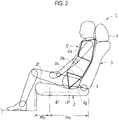
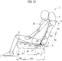
- a vehicle seat 1 for rear seat according to a first embodiment not in accordance with the present invention.
- the vehicle seat 1 for rear seat mainly includes a seat cushion 2 and a seat back 3 as shown in Fig. 1 .
- the seat back 3 is connected to a rear end portion of the seat cushion 2 via a reclining mechanism 5 so as to incline in a front-rear direction.
- a headrest 4 is provided at an upper end portion of the seat back 3.
- the seat cushion 2 includes at least a front part 2f and a rear part 2g.
- the front part 2f is a part including a front end portion of the seat cushion 2, and covers a range within about 1/6 to 1/3 of the thigh length (length from the great trochanter to the knee joint) of an occupant D from the front end of the seat cushion 2 in the side view of the seat cushion 2.
- the rear part 2g is a part positioned immediately behind the front part 2f (i.e., the part other than the front part 2f).
- the front part 2f of the seat cushion 2 is set as a low stiffness region PSc, while the rear part 2g of the seat cushion 2 is set as a high stiffness region PHc having stiffness higher than that of the low stiffness region PSc.
- a stiffness distribution having the low stiffness region PSc and the high stiffness region PHc in a front-rear direction is imparted to the seat cushion 2.
- the stiffness of the low stiffness region PSc and the high stiffness region PHc is adjusted accordingly by setting a spring constant of a pad material of the seat cushion 2 to be described later.
- a preferable spring constraint for the high stiffness region PHc is a standard spring constant usually required for the vehicle seat cushion, which allows the bases of the thighs of the occupant D to be firmly and elastically supported with the hip of the occupant D, which is the gravity center thereof, received as the load center.
- a spring constant for the low stiffness region PSc is set to an appropriate one which allows the lower thighs of the occupant D to be supported flexibly to an extent not making the occupant D feel uncomfortable due to sinking of the pad material.
- the mechanical properties such as stiffness of the respective areas PSc and PHc as well as positions, sizes, ranges and the like thereof are set based on the dimensions, weight and the like of each part of the body of the occupant D.
- 50 percentile of adult male of the country where production, sale, use and the like of the vehicle seat 1 are conducted can be adopted.
- dimensions and the like of each part of the vehicle seat 1 or mechanical properties such as stiffness thereof may also be set based on the dimensions, weight and the like of each part of the body of the occupant D.
- reference dimensions, weight and the like of the occupant D can also be set in the same manner as in the case of this embodiment.
- Fig. 3 is a diagram showing a relationship between a series of actions taken by the occupant D for seating seated in the vehicle seat 1 and the functions of the vehicle seat 1.
- the occupant D is seated. More specifically, the occupant D places his/her hip on a seating surface 2a of the seat cushion 2. In this event, the occupant D puts the hip on the seating surface 2a while leaving his/her left and right legs in positions at the time of getting into the rear seat (examples of the positions of the legs at the time of getting into the rear seat include, for example, a state where any one of the left and right legs is positioned inside a foot space in the rear seat and the other leg is positioned outside the vehicle, a state where the both legs are placed in the foot space while keeping the toes facing inward in a vehicle width direction, and the like).
- the body of the occupant D faces in a direction oblique to the front-rear direction of the vehicle seat 1.
- the occupant D turns around by rotating the body around the hip while moving the hip placed on the seating surface 2a of the seat cushion 2 to a predetermined position on the seating surface 2a, thereby adjusting the body direction to the front-rear direction of the vehicle seat 1.
- the occupant D presses his/her back against the backrest surface 3a of the seat back 3 to support the backbone on the seat back 3. In this event, the occupant D may move the hip on the seating surface 2a while pressing the back against the backrest surface 3a.
- the hip point HP means a point corresponding to the hip joint of the occupant D.
- the seat cushion 2 in the vehicle seat 1 comes into contact with the body of the occupant D, thus causing a reaction force (contact force) to act on the body of the occupant D.
- a reaction force contact force
- the rear part 2g the high stiffness region PHc
- the rear part 2g supports the movement and rotation of the hip on the seat cushion 2.
- the seat back 3 causes a reaction force to act on the back of the occupant D through the backrest surface 3a.
- the seat cushion 2 causes a reaction force to act on the lower body below the hip, such as the thighs, knees and leg regions of the occupant D through the seating surface 2a.
- the vehicle seat 1 For the series of actions taken by the occupant D for seating, the vehicle seat 1 according to this embodiment exerts the following functions while allowing the reaction forces to act on the body of the occupant D.
- the occupant D sits on the seat by bending the knee joints while positioning the knee joints in front of the hip joints. Since the lower portion below the knees of the occupant D seated is supported by the rear seat floor, the load applied to the seat cushion 2 is concentrated on the region right below the hip. Thus, the seat cushion 2 is deformed such that the region right below the hip sinks more deeply than the region therearound. Due to this sinking deformation, the front side of the seating surface 2a in front of the region right below the hip forms an inclined surface which is inclined (inclined backward) upward toward the front.
- the knee-bent posture a posture with his/her knees bent upward
- the high stiffness region PHc is provided in the rear part 2g of the seat cushion 2, and relatively high stiffness is imparted to the high stiffness region PHc.
- a sinking amount of the cushion pad in the region right below the hip of the occupant D is adequately suppressed. Accordingly, resistance to the backward movement of the hip is reduced, thus facilitating backward movement of the occupant D on the seating surface 2a.
- the high stiffness region PHc suppresses excessive sinking of the cushion pad also when the occupant D turns around.
- the low stiffness region PSc is provided in the front part 2f of the seat cushion 2, and the front part 2f is deformed with a relatively small load when the knees or lower legs of the occupant D come into contact therewith.
- the resistance to the movement or turnaround of the occupant D on the seating surface 2a is further reduced.
- the front part 2f of the seat cushion 2 is set as the low stiffness region PSc and the rear part 2g is set as the high stiffness region PHc.
- This structure suppresses the resistance to the series of actions (particularly, backward movement and turnaround of the occupant D on the seat cushion 2) taken by the occupant D after getting into the rear seat until the completion of the turnaround, thereby easily guiding the hip point HP of the occupant D to an optimum position.
- the occupant D After the occupant D turns around on the seating surface 2a and moves the hip point HP further backward on the seating surface 2a, the occupant D leans back on the seat back 3 to support the back bone on the seat back 3, and then finally makes final adjustment on the position of the hip point HP.
- the lower thighs, the posterior knees, the posterior lower legs, and the like of the occupant D may be pressed against the front part 2f of the seat cushion 2 with a relatively high pressure.
- the low stiffness region PSc is provided in the front part 2f of the seat cushion 2. Since the low stiffness region PSc can be deformed with a relatively small load, the occupant D can position the hip further backward on the seating surface 2a. As a result, an actual foot space of the vehicle seat 1 is expanded.
- the occupant D may shift the position of the hip point HP with the load of the hip reduced by pushing the floor surface with the legs while pressing the back against the backrest surface 3a of the seat back 3.
- the low stiffness region PSc is provided in the front part 2f of the seat cushion 2. Since the low stiffness region PSc is deformed with a relatively small load, the occupant D can easily stretch his/her legs when pushing the floor surface with the legs.
- the seat cushion 2 sinks more deeply than in the case of the small-build person.
- the inclination angle of the seating surface 2a in front of the hip is also increased.
- the high stiffness region PHc is provided in the rear part 2g of the seat cushion 2, and the resistance to the backward movement of the occupant D is suppressed.
- the hip of the occupant D is readily guided backward along the seating surface 2a largely inclined, and the occupant D is readily guided to the knee-bent posture. Accordingly, a knee room positioned in front of the knees of the occupant D is secured at an early stage after the start of the seating action. As a result, an effect that is equivalent to actually expanding a knee room can be achieved..
- the load (pressure) applied to the seating surface 2a by the occupant D can be changed by the movement of the occupant D himself/herself, vibration of the vehicle generated during running, and the like.
- the high stiffness region PHc is provided in the rear part 2g of the seat cushion 2, and the stiffness of the cushion pad below the hip of the occupant D is higher.
- the occupant D is in the knee-bent posture while seated in the vehicle seat 1, and the gravity center thereof is closer to the back side.
- the hip of the occupant D tends to slide further backward.
- the high stiffness region PHc is provided in the rear part 2g of the seat cushion 2, thus reducing the resistance to the backward movement of the occupant D on the seating surface 2a. Accordingly, the hip of the occupant D is likely to slide further backward.
- the vehicle seat 1 includes the seat back 3, and the hip trying to move further backward is received from the back by the seat back 3.
- the hip of the occupant D is stably held at a position where the backward sliding force and the forward pressing force of the seat back 3 are balanced with each other. As a result, the positional shift in the hip point HP is more surely prevented.
- the seating surface 2a of the vehicle seat 1 has a maximum deformation part LP between the rearward inclined surface and the backrest surface 3a of the seat back 3.
- the maximum deformation part LP is a point where a deformation amount (sinking amount) caused by the load by the seating is at its maximum or a point set to have a maximum deformation amount.
- the maximum deformation part LP is positioned approximately in the center in the front-rear direction of the high stiffness region PHc.
- the vehicle seat 1 supports the pelvis Dc of the occupant D with the maximum deformation part LP, and thus the pelvis Dc is stably held in a constant posture.
- the positional shift in the hip point HP is more surely prevented.
- the vehicle seat 1 includes the seat cushion 2 and the seat back 3. Moreover, the low stiffness region PSc which is more flexible than the rear part 2g that is the high stiffness region PHc is provided in the front part 2f of the seat cushion 2, thereby imparting a stiffness distribution in the front-rear direction to the seat cushion 2.
- the above three functions i.e., the HP guide function, the space expansion function and the HP shift prevention function can be simultaneously achieved during the series of actions taken by the occupant D for seating in the vehicle seat 1.
- the low stiffness region PSc which is more flexible than the rear part 2g that is the high stiffness region PHc is provided in the front part 2f of the seat cushion 2.
- the vehicle seat 1 can provide good seating comfort by firmly supporting the bases of the thighs with the hip of the occupant D, which is the gravity center thereof, received as the load center, and also by flexibly supporting the lower thighs by the low stiffness region PSc.
- reduction in a feeling of pressure on the posterior lower legs and the posterior knees of the occupant D allows the occupant to get the seating comfort.
- a vehicle seat 1 for rear seat according to a second embodiment not in accordance with the present invention.
- This embodiment is an example where a stiffness distribution described below is imparted to the seat back 3 in the vehicle seat 1 of the first embodiment.
- a low stiffness region PSb having a support reaction force fa 1 for the occupant D is set in the vertical center portion thereof.
- the support reaction force is a force that the occupant D receives from a surface (e.g., the backrest surface 3a) on which the occupant D is supported.
- the support reaction force can be determined based on the maximum deformation amount (sinking amount) of a supporting surface in a state where a pressing surface having a predetermined shape and size is pressed against the supporting surface with a predetermined pressure.
- the support reaction force of the supporting surface X is smaller than that of the supporting surface Y.
- high stiffness regions PHb 1 and PHb 2 each having a larger support reaction force fa 2 for the occupant D than the support reaction force fa 1 of the low stiffness region PSb are set, adjacent to the low stiffness region PSb in the vertical direction, in upper and lower portions of the seat back 3.
- the seat back 3 is given a stiffness distribution having different reaction force characteristics in the vertical direction.
- the high stiffness regions PHb 1 and PHb 2 have a standard spring constant normally required for the vehicle seat back, which allows the corresponding body part of the occupant D to be firmly and elastically supported with less sinking due to elastic deformation when the occupant D leans back on the backrest surface 3a of the seat back 3.
- the low stiffness region PSb is set to have an appropriate spring constant which allows relatively flexible elastic deformation and sinking against a backrest load acting on the seat back 3.
- the backrest load is a load applied to the backrest surface 3a of the seat back 3 by the back of the occupant D in a seated state.
- the backrest surface 3a of the seat back 3 can be bent in the middle at the foregoing low stiffness region PSb at any of various middle bend angles, in a shallow V shape in the side view, for example, according to the backrest load of the occupant D.
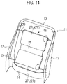
- the high stiffness region PHb 1 in the upper portion of the seat back 3 is formed to approximately correspond to a chest Da of the occupant D
- the high stiffness region PHb 2 in the lower portion thereof is formed to approximately correspond to the pelvis Dc of the occupant D.
- the low stiffness region PSb in the vertical center portion of the seat back 3 is formed to have a required vertical width dimension having its center at a body part of the occupant D corresponding to the vicinity of the joints of the chest Da and a waist Db, i.e., the tenth thoracic vertebra Da 1 to the twelfth thoracic vertebra Da 2 .
- the backrest surface 3a can be bent in the middle at a vertical center position PS 0 of the low stiffness region PSb as a bend point BP, in response to the backrest load.
- the support reaction force fa gets larger in the downward direction from the center to a lower end portion of the backrest surface 3a.
- the pelvis Dc can be firmly supported.
- the support reaction force fa gets larger in the upward direction from the center to an upper end portion of the backrest surface 3a.
- the chest Da can be supported, in particular.
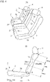
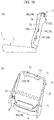
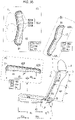
- Part (A) of Fig. 6 is a cross-sectional view showing a structure of the seat back 3, and part (B) of Fig. 6 is a perspective view showing a structure of a seat back frame of the seat back 3.
- Fig. 5 and part (A) of Fig. 6 show the seat back 3 in a state where a trim cover is removed, which includes a surface material covering a cushion pad.
- the seat back 3 includes a seat back frame 11, a cushion pad 15 and a pad supporting member 16 to support the cushion pad 15 on the seat back frame 11 at the back side of the cushion pad 15.
- the seat back frame 11 includes a pair of left and right side frames 12, an upper frame 13 made of a pipe material connecting upper ends of the side frames, and a lower frame 14 connecting lower ends thereof.
- the cushion pad 15 is formed of an elastic material having a required thickness, which is made of urethane foam or the like, for example, to elastically support the occupant D.
- the cushion pad 15 is provided to entirely cover the front side of the seat back frame 11, as shown in part (A) of Fig. 6 .
- a groove 15a to facilitate middle bending of the cushion pad 15 is formed extending in the vehicle width direction in the vertical center portion (the vertical center position PS 0 in this embodiment) of the low stiffness region PSb.
- the cushion pad 15 is preferably formed such that the backrest surface 3a is formed beforehand into the shallow V shape with the groove 15a provided as the middle bending point in order to facilitate the middle bending in seating.
- the groove 15a is provided on the front surface of the cushion pad 15.
- the groove may be provided on a rear surface of the cushion pad 15 as indicated by the chain line in part (A) of Fig. 6 or may be provided on both front and rear surfaces.
- the pad supporting member 16 includes an upper pad supporting member 16U, a lower pad supporting member 16L and a center pad supporting member 16C.
- the upper pad supporting member 16U supports the upper portion of the cushion pad 15 at the position corresponding to the chest Da of the occupant D.
- the lower pad supporting member 16L supports the lower portion of the cushion pad 15 at the position corresponding to the pelvis Dc of the occupant D.
- the center pad supporting member 16C supports the vertical direction center part of the cushion pad 15 at the position corresponding to the vicinity of the joints of the chest Da and the waist Db of the occupant D.
- pad supporting members 16U, 16L and 16C are set to have different mechanical properties such as stiffness and softness, thereby setting the high stiffness regions PHb 1 and PHb 2 and the low stiffness region PSb described above.
- the upper pad supporting member 16U is formed as a horizontally long metal box structure joined to the front surface of the upper frame 13 along the vehicle width direction.
- the box structure supports the upper end back surface of the cushion pad 15 at a portion corresponding to the upper end of the chest Da of the occupant D, thereby obtaining a large support reaction force fa 2 .
- the horizontally long box structure 16U also serves as a mounting member for the headrest 4, and is provided with vertically penetrating stay insertion holes 17 at both left and right ends, into which a headrest stay is inserted.
- the lower pad supporting member 16L is made of a metal rod having left and right ends joined to leading edge flanges of left and right side frames 12.
- the metal rod supports the lower end back surface of the cushion pad 15 at a portion corresponding to the upper end of the pelvis Dc of the occupant D, thereby obtaining a large support reaction force fa 2 .
- the center pad supporting member 16C is made of a metal S spring having left and right ends joined to rear edge flanges of the left and right side frames 12 or the leading edge flanges.
- the S spring 16C is set to have a required small spring constant, and supports the center back surface of the cushion pad 15 at a lower position of the groove 15, thereby obtaining a small support reaction force fa 1 .
- the vehicle seat 1 exerts the following functions.
- the vertical center portion of the seat back 3 is provided with the low stiffness region PSb having a small support reaction force fa 1 for the occupant D
- the upper and lower portions of the seat back 3 are provided with the high stiffness regions PHb 1 and PHb 2 , each having a large support reaction force fa 2 for the occupant D, adjacent to the low stiffness region PSb.
- the stiffness distribution having different reaction force characteristics in the vertical direction of the seat back 3 is imparted. Accordingly, the backrest surface 3a of the seat back 3 can be bent in the middle at the low stiffness region PSb at any of various middle bend angles according to the backrest load of the occupant D.
- the support reaction force fa (fa 1 and fa 2 ) varies according to the backrest load to act thereon.
- the middle bend angle of the backrest surface 3a varies according to the body size of the occupant D. More specifically, when a small person (small-build person) who is lighter than the standard occupant D is seated, the amount of sinking of the center portion of the backrest surface 3a is small, and thus the middle bend angle is small. On the other hand, when a large person (large-build person) who is heavier than the standard occupant D is seated, the amount of sinking of the center portion of the backrest surface 3a is large, and thus the middle bend angle is large.
- the backrest surface 3a can be automatically bent in the middle at a middle bend angle which achieves a comfortable posture most suitable for the body side of the occupant D, without the need to perform a special adjustment operation, just by leaning back on the seat back 3.
- fatigue of the occupant D can be reduced.
- the vehicle seat 1 includes the front part 2f of the seat cushion 2 as the low stiffness region PSc and the rear part 2g thereof as the high stiffness region PHc.
- an HP guide function, a space expansion function and an HP shift prevention function can be exerted for the series of actions taken by the occupant D for seating described in the first embodiment.
- the stiffness distribution including the high stiffness region PHb 1 , the low stiffness region PSb and the high stiffness region PHb 2 , which have different reaction force characteristics in the vertical direction of the seat back 3, is imparted as described above.
- the backrest surface 3a of the seat back 3 can be bent in the middle according to the backrest load of the occupant D. Accordingly, the back of the occupant D leaning back on the seat back 3 is gently curved to protrude backward. As a result, the occupant D can more easily move the hip backward, and guide the hip point HP to the optimum position.
- the backrest surface 3a of the seat back 3 is bent in the middle at the middle bend angle which allows a comfortable posture most suitable for the body size of the occupant D by the automatic adjustment function for the middle bend angle described above.
- the occupant D can more easily move the hip backward, and surely guide the hip point HP to the optimum position.
- the occupant D may adjust the hip position by pushing the floor surface with his/her legs while pressing the back against the backrest surface 3a of the seat back 3.
- a reaction force from the high stiffness region PHb 1 in the upper portion of the backrest surface 3a acts on the back of the occupant D.
- the stiffness distribution having different reaction force characteristics in the vertical direction of the seat back 3 is imparted.
- the backrest surface 3a of the seat back 3 can be bent in the middle according to the backrest load of the occupant D.
- the stiffness distribution having different reaction force characteristics in the vertical direction of the seat back 3 is imparted. Accordingly, the backrest surface 3a of the seat back 3 can be bent in the middle according to the backrest load of the occupant D. Thus, the size of the space in front of the backrest surface 3a can be changed automatically based on the body size of the occupant D. More specifically, when the large-build person is seated, the backrest surface 3a is bent in the middle at a larger middle bend angle than in the case where the small-build person is seated. Accordingly, a larger space is generated in front of the backrest surface 3a (particularly, the vertical center portion (low stiffness region PSb) of the backrest surface 3a).
- the backrest surface 3a receives the back of the occupant D arriving after moving backward along with the movement of the hip on the seating surface 2a, while bending by the middle bend amount (the front-rear direction movement amount of the backrest surface 3a in the low stiffness region PSb relative to the high stiffness regions PHb 1 and PHb 2 , along with the middle bend) according to the body size of the occupant D. Therefore, in the vehicle seat 1 according to this embodiment, even when the large-build person is seated, for example, the backrest surface 3a does not hinder the backward movement of the hip. As a result, smooth backward movement of the hip can be more surely realized. Thus, a knee room of the occupant D is secured at an earlier stage after the start of the seating action, and an actual knee room expansion effect can be more surely achieved.
- the backrest surface 3a of the seat back 3 is bent in the middle at the middle bend angle which allows a comfortable posture most suitable for the body size of the occupant D by the automatic adjustment function for the middle bend angle described above. Accordingly, the occupant D can obtain a comfortable posture most suitable for his/her body size just by leaning back on the seat back 3. Thus, a feeling of spaciousness the occupant D experiences, regardless of the body size, is improved.
- the high stiffness region PHc is provided in the rear part 2g of the seat cushion 2, thereby reducing the resistance to the backward movement on the seating surface 2a of the occupant D.
- the hip of the occupant D in the knee-bent posture tends to slide further backward.
- the high stiffness region PHb 2 having a large support reaction force fa 2 for the occupant D is set in the lower portion of the seat back 3.
- the hip trying to move further backward is received more surely from the back by the high stiffness region PHb 2 .
- a positional shift in the hip point HP can be more surely prevented.
- the stiffness distribution having different reaction force characteristics is imparted in the vertical direction of the seat back.
- the backrest surface 3a of the seat back 3 can be bent in the middle according to the backrest load of the occupant D. Accordingly, a downward component is added to the reaction force acting on the back of the occupant D from the high stiffness region PHb 1 of the backrest surface 3a.
- the downward component acts to press the hip of the occupant D in a seated state against the seating surface 2a.
- the positional shift in the hip point HP in the seated state is more surely prevented.
- the vehicle seat 1 of the second embodiment has the following configuration in addition to the configuration of the first embodiment described above.
- the low stiffness region PSb having a small support reaction force fa 1 for the occupant D is set in the vertical center portion of the seat back 3,.
- the high stiffness regions PHb 1 and PHb 2 having a large support reaction force fa 2 for the occupant D are set, adjacent to the low stiffness region PSb, in the upper and lower portions of the seat back 3.
- the stiffness distribution having different reaction force characteristics is imparted in the vertical direction of the seat back 3.
- the backrest surface 3a of the seat back 3 can be bent in the middle at the low stiffness region PSb at any of various middle bend angles according to the backrest load of the occupant D.
- the above three functions i.e., the HP guide function, the space expansion function and the HP shift prevention function can be simultaneously achieved during the series of actions taken by the occupant D for seating in the vehicle seat 1.
- vehicle seat 1 also exerts functions to improve visibility of the outside of the window and seating comfort described below.
- the stiffness distribution including the high stiffness region PHb 1 , the low stiffness region PSb and the high stiffness region PHb 2 which have different reaction force characteristics, is imparted in the vertical direction of the seat back 3.
- the backrest surface 3a of the seat back 3 can be bent in the middle according to the backrest load of the occupant D.
- the chest Da of the occupant D can be lifted at a moderate angle in accordance with the backward inclination angle of the seat back 3 (or the body size of the occupant D).
- the visibility of the outside of the window (front and side visibility) of the occupant D can be improved.
- the posterior lower legs and the posterior knees come into contact with the front surface of the front part 2f of the seat cushion 2 upon middle bending of the backrest surface 3a since the thigh length is shorter than that of the large-build person D2.
- the person tends to feel pressure on the posterior lower legs and the posterior knees.
- the backward inclination angle of the seat back 3 is set large, the degree of contact of the seat cushion front part 2f with the posterior lower legs and the posterior knees is increased, and thus the person tends to feel higher pressure. This can happen to the large-build person D2 too.
- the occupant D when the occupant D is the large-build person D2, the occupant D makes the middle bend angle of the backrest surface 3a of the seat back 3, large and may strongly feel pressure on the posterior lower legs and the posterior knees as the front part 2f of the seat cushion 2 comes into contact therewith, under the setting of the large backward inclination angle of the seat back 3.
- the front part 2f of the seat cushion 2 is provided with the low stiffness region PSc which is more flexible than the rear part 2g that is the high stiffness region PHc.
- the bases of the thighs are firmly supported with the hip of the occupant D, which is the gravity center thereof, received as the load center.
- the lower thighs are flexibly supported with the low stiffness region PSc.
- the front part 2f of the seat cushion 2 is flexibly deformed with the load from the lower thighs, the posterior knees and the posterior lower legs, thus reducing the feeling of pressure on the small-build person and on the large-build person in some cases.
- a synergistic effect is achieved by combining middle bending of the backrest surface 3a of the seat back 3 at an optimum angle based on the body size of the occupant D with reduction in the feeling of pressure on the posterior lower legs and posterior knees by flexible deformation of the front part 2f of the seat cushion 2. More specifically, according to this embodiment, good seating stability and comfortable and easy seating posture can be achieved to reduce the fatigue of the occupant regardless of whether he/she is a large-build person or a small-build person.
- the vehicle seat 1 according to this embodiment further exerts the following functions.
- the high stiffness region PHb 1 set in the upper portion of the seat back 3 is formed so as to approximately correspond to the chest Da of the occupant D
- the high stiffness region PHb 2 set in the lower portion of the seat back 3 is formed so as to approximately correspond to the pelvis Dc of the occupant D.
- the low stiffness region PSb set in the vertical center portion of the seat back 3 is formed around the portion approximately corresponding to the joints of the chest Da and the waist Db. Accordingly, the vertical center position PS 0 of the low stiffness region PSb approximately corresponds to the joints of the chest Da and the waist Db of the occupant D, and the backrest surface 3a is bent in the middle with the vertical center position PS 0 as the bend point BP.
- this embodiment establishes the support structure suitable for the human body frame, and allows the occupant D to take the seating posture having less posture change and less muscle burden. As a result, a fatigue reduction effect can be achieved.
- the cushion pad 15 of the seat back 3 includes the groove 15a to facilitate middle bending of the cushion pad 15, the groove 15a extending in the vehicle width direction in the vertical center portion of the low stiffness region PSb.
- the groove 15a is set as the bend point BP of the backrest surface 3a to allow for stable middle bending of the backrest surface 3a.
- the seat back 3 includes the pad supporting members 16 configured to support the cushion pad 15 on the seat back frame 11 at the back side thereof.
- the high stiffness regions PHb 1 and PHb 2 and the low stiffness region PSb are set by allowing the pad supporting members 16 to have different mechanical properties such as stiffness. Thus, the stiffness of each area can be easily adjusted to the requirements.
- the upper pad supporting member 16U is formed as the metal box structure, i.e., a rigid structure.
- the high stiffness region PHb 1 can be set to have appropriate stiffness which allows the chest Da to be firmly supported.
- the metal rod is used as the lower pad supporting member 16L
- the S spring is used as the center pad supporting member 16C.
- the spring constant is arbitrarily set by selecting wire diameters, materials and the like of those members.
- the high stiffness region PHb 2 and the low stiffness region PSb can be easily set to have stiffness suitable for supporting the pelvis Dc, supporting the waist Db and middle bending, individually.
- the bend point BP of the backrest surface 3a of the seat back 3 is determined based on the standard body size of the occupant. However, in the case where the occupant is the large-build person D2, it is conceivable that the joint positions of the chest Da and the waist Db are shifted above the bend point BP as shown in part (B) of Fig. 7 .
- the hardness of the cushion pad immediately below the hip point HP of the seat cushion 2 may be set to appropriate hardness. More specifically, the hardness may be set such that the sinking amount below the hip point HP is increased when the large-build person is seated and the sinking amount below the hip point HP is reduced when the small-build person is seated.
- Fig. 8 shows an example of hardness adjustment below the hip point HP of the seat cushion 2.
- a void part 51 such as a hollow space 51A or multiple vertical slits 51B, is provided in the surface of the pad member 41A, which is opposite to the seating surface at the hip point HP.
- This void part 51 allows large sinking deformation below the hip point HP when the large-build person is seated and small sinking deformation therebelow when the small-build person is seated, thereby absorbing a shift in joint position between the chest Da and the waist Db, which is caused by a difference in body size of the occupant.
- Part (A) of Fig. 9 shows a cross-sectional structure of a seat back 3 and part (B) of Fig. 9 shows a structure of a seat back frame 11 according to the first modified example of the second embodiment.
- an S spring is used as a lower pad supporting member 16L, as in the case of a center pad supporting member 16C, instead of the metal rod in the second embodiment.
- the S spring 16L as the lower pad supporting member is set to have a spring constant larger than that of the S spring 16C as the center pad supporting member, thereby enabling a pelvis Dc of an occupant D to be firmly supported.
- the S springs are used as the center pad supporting member 16C and the lower pad supporting member 16L, and specifications of the S springs are selected, respectively.
- the stiffness of the high stiffness region PHb 2 and low stiffness region PSb can be easily adjusted.
- the lower pad supporting member 16L is formed of the S spring, the supporting area of the portion corresponding to the pelvis Dc is increased.
- variations in support reaction force from the low stiffness region PSb to the high stiffness region PHb 2 can be smoothed out to achieve good seating comfort.
- Part (A) of Fig. 10 shows a cross-sectional structure of a seat back 3 and part (B) of Fig. 9 shows a structure of a seat back frame 11 according to a second modified example of the second embodiment.
- a horizontally long load receiving plate is used as a lower pad supporting member 16L instead of the metal rod in the second embodiment.
- the load receiving plate 16L is made of a rigid plate such as a metal plate or a hard resin plate, and is connected to left and right side frames 12 such that its position in the front-back direction can be adjusted by rotation using an actuator 18 or manual rotation.
- the high stiffness region PHb 2 can be set to have appropriate stiffness that allows the pelvis Dc to be firmly supported, by setting the spring constant of the cushion pad 15 itself. Moreover, the supporting area of the portion corresponding to the pelvis Dc can be increased to stabilize the seating posture.
- the position of the load receiving plate 16L in the front-back direction is adjusted based on a difference in the size of the hip of the occupant D.
- a hip supporting structure that fits the body size of the occupant D can be realized.
- a large support reaction force fa 2 can be obtained by forming the lower pad supporting member 16L using the load receiving plate made of metal or hard resin and by supporting the lower end back surface of the cushion pad 15 with a large area in the portion corresponding to the pelvis Dc of the occupant D.
- Part (A) of Fig. 11 shows a cross-sectional structure of a seat back 3 and part (P) of Fig. 11 shows a structure of a seat back frame 11 according to a third modified example of the second embodiment.
- a horizontally long metal load receiving plate is used as a lower pad supporting member 16L instead of the metal rod in the second embodiment.
- the load receiving plate 16L is connected to left and right side frames 12 by setting an appropriate forward protrusion amount, and the thickness of the cushion pad 15 in the portion opposite thereto is adjusted.
- the high stiffness region PHb 2 is set to have stiffness suitable for supporting the pelvis Dc.
- the supporting area in the portion corresponding to the pelvis Dc can be increased to stabilize the seating posture. Moreover, a large support reaction force fa 2 can be obtained with a simpler configuration.
- Figs. 12 to 14 show other examples of the pad supporting member 16, respectively.
- the pad supporting member 16 includes a pair of left and right rigid rods 21 extending in the vertical direction, and multiple S springs 22 provided in multiple stages in the vertical direction between the rigid rods 21 and 21.
- the rigid rods 21 and 21 are connected at its upper and lower ends by wires 23, and the upper and lower ends are connected to side frames 12 in the vicinity thereof by connection rods 24.
- the upper S spring 22U and the lower S spring 22L are provided at positions corresponding to the chest Da and the pelvis Dc of the occupant D. Meanwhile, other two center S springs 22C are provided above and below a bend point BP (a groove 15a) of the cushion pad 15, at positions corresponding to the vicinities of the joints of the chest Da and the waist Db of the occupant D.
- the upper and lower S springs 22U and 22L are set to have large spring constants required to firmly support the chest Da and the pelvis Dc of the occupant D.
- each of the center S springs 22C is set to have a small spring constant required to allow the cushion pad 15 to be bent in the middle at the groove 15a by the backrest load.
- the pad supporting member 16 includes the pair of left and right rigid rods 21 extending in the vertical direction, and the multiple S springs 22 provided in multiple stages in the vertical direction between the rigid rods 21.
- the arrangement, stiffness and the like of the respective areas PHb 1 , PSb and PHb 2 can be easily adjusted by determining the spring constants of the S springs 22U, 22C and 22L and adjusting the arrangement thereof.
- the upper and lower ends of the rigid rods 21 and 21 are connected by the wires 23, and are connected to the side frames 12 in the vicinity thereof by the connection rods 24.
- the stiffness of the entire backrest surface 3a can be easily adjusted.
- a pad supporting member 16 includes a pair of left and right elastic rods 25 extending in the vertical direction, and coil springs 26 supporting upper, center and lower portions of the elastic rods 25 and 25 on side frames 12 in the vicinities thereof.
- the pair of left and right elastic rods 25 are made of a suitable synthetic resin material which allows for flexible deformation by backrest load.
- the elastic rods are connected to each other by multiple wires 23 provided in multiple stages in the vertical direction, and configured to support the back surface of the cushion pad 15 together with the wires 23.
- the upper coil spring 26U and the lower coil spring 26L are arranged in positions corresponding to side portions of the chest Da and the pelvis Dc of the occupant D. Meanwhile, the center coil spring 26c is arranged in a position corresponding to a side portion in the vicinity of the joints of the chest Da and the waist Db of the occupant D.
- the upper and lower coil springs 26U and 26L are set to have large spring constants required to firmly support the chest Da and the pelvis Dc of the occupant D.
- the center coil spring 26C is set to have a small spring constant required to allow the elastic rod 25 to be flexibly deformed into a shallow V shape in its center portion and to allow the cushion pad 15 to be bent in the middle at the groove 15a by the backrest load.
- the arrangement, stiffness and the like of the respective areas PHb 1 , PSb and PHb 2 can be easily adjusted by setting the stiffness of the elastic rods 25 and determining the spring constants of the coil springs 26U, 26C and 26L.
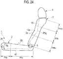
- a pad supporting member 16 includes a pair of upper and lower load receiving plates 27 and a connection plate 28 connecting those plates.
- the upper load receiving plate 27U has its upper end connected to left and right side frames 12 with a support shaft 29 so as to be rotatable in the front-back direction at a position approximately corresponding to the upper end of the chest Da of the occupant D.
- the lower load receiving plate 27L has its lower end connected to the left and right side frames 12 with a support shaft 29 so as to be rotatable in the front-back direction at a position approximately corresponding to the upper end of the pelvis Dc of the occupant D.
- the load receiving plates 27 are formed using rigid plates made of metal or hard synthetic resin, while the connection plate 28 is made of a plate spring.
- connection plate 28 is provided at a position corresponding to the vicinity of the joints of the chest Da and the waist Db of the occupant D.
- the connection plate 28 is set to have a required small spring constant such that the upper and lower load receiving plates 27U and 27L are rotated in the arrow direction shown in Fig. 14 around the support shaft 29 by the backrest load and the cushion pad 15 can be bent in the middle at the groove 15a.
- the pad supporting member 16 includes the pair of upper and lower load receiving plates 27 and the connection plate 28 connecting those plates.
- a bending moment generated by the backrest load can be concentrated on the connection plate 28, and the middle bending of the backrest surface 3a can be more surely realized.
- the present invention is not limited to the cushion pad supporting structure described in the above embodiments and modified examples, but is applicable to any cushion pad supporting structure which can achieve the stiffness distribution shown in Fig. 4 in the vertical direction of the seat back 3.
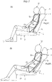
- a vehicle seat 1 for rear seat according to a third embodiment not in accordance with the present invention.
- This embodiment is an example where reaction force characteristics described below are imparted to the front part 2f of the seat cushion 2 in the vehicle seat 1 of the first embodiment.
- a low stiffness region PSc provided in a front part 2f of a seat cushion 2 is given reaction force characteristics of having a large support reaction force fb for a seating load applied from the above, and a small support reaction force fc for a seating load applied from the front. That is, the low stiffness region PSc is given such reaction force characteristics that the support reaction force fb for the seating load applied from the above is greater than the support reaction force fc for the seating load applied from the front (fb > fc) .
- the seating load is a load applied to the seat cushion 2 from a body part of an occupant D lower than the waist in seating.
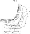
- Fig. 16 shows a structure of the front part of the seat cushion 2 of this embodiment in a state where a surface material covering a cushion pad 41 is removed for convenience.
- the seat cushion 2 includes the cushion pad 41 made of urethane foam or the like and a seat cushion base member 47 such as a seat cushion pan and a seat cushion frame supporting the cushion pad 41.
- the low stiffness region PSc of the front part 2f of the seat cushion 2 is set to include a portion (lower posterior thigh contact portion) PSc 1 to be in contact with the lower posterior thighs of the occupant D, a portion (posterior knee contact portion) PSc 2 to be in contact with the posterior knees, and a portion (posterior lower leg contact portion) PSc 3 to be in contact with the posterior lower legs, which are shown in Fig. 16 .
- Support reaction forces of the lower posterior thigh contact portion PSc 1 , the posterior knee contact portion PSc 2 , and the posterior lower leg contact portion PSc 3 are set to satisfy a relation of the lower posterior thigh contact portion PSc 1 > the posterior knee contact portion PSc 2 > the posterior lower leg contact portion PSc 3 .
- the low stiffness region PSc is given the reaction force characteristics of having the large support reaction force fb for the seating load applied from the above and the small support reaction force fc for the seating load applied from the front.
- the cushion pad 41 is formed of: a standard pad material 41A used in a high stiffness region PHc of a rear part 2g of the seat cushion 2 and set to have a required spring constant; and a pad material 41B used in the low stiffness region PSc of the front part 2f of the seat cushion 2.
- a pad material 41B used is a pad material 42 with such reaction force characteristics that support reaction forces therefrom have directional properties (for example, such reaction force characteristics that the upward support reaction force fb is greater than the forward support reaction force fc (fb > fc)).
- the reaction force characteristics of the pad material 42 as above can be easily set through adjustment of the form density inside the pad material 42 or the like, for example.
- the vehicle seat 1 includes the front part 2f of the seat cushion 2 as the low stiffness region PSc and the rear part 2g thereof as the high stiffness region PHc.
- an HP guide function, a space expansion function and an HP shift prevention function can be exerted for the series of actions taken by the occupant D for seating described in the first embodiment.
- the low stiffness region PSc of the seat cushion 2 is given the reaction force characteristics of having the large support reaction force fb for the seating load applied from the above and the small support reaction force fc for the seating load applied from the front.
- the front part 2f is flexibly deformed in response to the seating load applied from the front due to contact of the knees or the lower legs therewith.
- resistance to a movement or turnaround of the occupant D on a seating surface 2a is surely reduced.
- the low stiffness region PSc of the seat cushion 2 is given the reaction force characteristics of having the large support reaction force fb for the seating load applied from the above and the small support reaction force fc for the seating load applied from the front.
- the downward sinking amount of the front part 2f of the seat cushion 2 is suppressed, thereby more stably supporting the lower posterior thighs.
- the front part 2f is flexibly deformed in response to the seating load applied from the front.
- a foot space can be surely secured.
- the low stiffness region PSc of the seat cushion 2 is given the reaction force characteristics of having the large support reaction force fb for the seating load applied from the above and the small support reaction force fc for the seating load applied from the front.
- the downward sinking amount of the front part 2f of the seat cushion 2 is suppressed, thereby more stably supporting the lower posterior thighs.
- a reaction force for the seating load applied from the front is small.
- the vehicle seat 1 of the third embodiment is configured such that the low stiffness region PSc of the seat cushion 2 is given the reaction force characteristics of having the large support reaction force fb for the seating load applied from the above and the small support reaction force fc for the seating load applied from the front,
- the above three functions i.e., the HP guide function, the space expansion function and the HP shift prevention function can be simultaneously achieved more surely during the series of actions taken by the occupant D for seating in the vehicle seat 1.
- vehicle seat 1 exerts functions described below.
- the vehicle seat 1 of this embodiment is configured such that the low stiffness region PSc of the seat cushion 2 is given the reaction force characteristics of having the large support reaction force fb for the seating load applied from the above and the small support reaction force fc for the seating load applied from the front,
- the occupant can obtain stable seating and a comfortable seating posture. Accordingly, fatigue due to long driving can be reduced.
- stable seating and a comfortable seating posture can be obtained similarly in a case of using the vehicle seat 1 as the driver's seat as well, as a matter of course.
- the support reaction force for the driver's lower posterior thighs is maintained appropriately, thereby never affecting pedal operations and the like.
- the low stiffness region PSc of the seat cushion 2 is set to include the lower posterior thigh contact portion PSc 1 , the posterior knee contact portion PSc 2 and the posterior lower leg contact portion PSc 3 .
- the occupant D can be seated in the seating surface 2a of the seat cushion 2 on a side closer to the rear than otherwise.
- the support reaction forces of the lower posterior thigh contact portion PSc 1 , the posterior knee contact portion PSc 2 and the posterior lower leg contact portion PSc 3 are set to satisfy the relation of the lower posterior thigh contact portion PSc 1 > the posterior knee contact portion PSc 2 > the posterior lower leg contact portion PSc 3 .
- the change in the support reaction forces is made gentle, making it possible to provide the occupant D with seating comfort without awkwardness.
- the pad material 41B used is the pad material 42 with such reaction force characteristics that the support reaction forces thereof have directional properties (for example, such reaction force characteristics that the upward support reaction force fb is greater than the forward support reaction force fc (fb > fc)).
- the pad material 42 it is possible, with only the pad material 42, to support the lower posterior thighs on the lower posterior thigh contact portion PSc 1 with the large support reaction force fb and to support the posterior lower legs on the posterior lower leg contact portion PSc 3 with the small support reaction force fc that causes no feeling of pressure.
- a support reaction force between the support reaction forces fb and fc is generated by the posterior knee contact portion PSc 2 for a posterior knee load applied from a front side which is slightly from above.
- reaction force characteristics can be obtained by means of the single pad material 42.
- increase in the number of components and the man-hour for assembly can be suppressed, thereby offering an advantage in terms of cost.
- Fig. 17 shows a first modified example of this embodiment.
- the configuration is such that the pad material 41B used in the low stiffness region PSc is divided into a pad material 43 disposed in a portion corresponding to the lower posterior thigh contact portion PSc1, a pad material 44 disposed in a portion corresponding to the posterior knee contact portion PSc2, and a pad material 45 disposed in a portion corresponding to the posterior lower leg contact portion PSc3.
- pad materials 43, 44, and 45 used are ones obtained through simple foaming at uniform densities, respectively.
- the pad material 43 is set to have a required spring constant which can provide the upward support reaction force fb
- the pad material 45 is set to have a required spring constant which can provide a forward support reaction force fc1 for load from the front.
- the pad material 44 is set to have a required spring constant which can provide a forward support reaction force fc2 between the pad material 43 and the pad material 45.
- the front part 2f of the seat cushion 2 is formed by using the pad materials 43, 44 and 45 having different spring constants in the portions corresponding to the lower posterior thigh contact portion PSc1, the posterior knee contact portion PSc2 and the posterior lower leg contact portion PSc3, respectively.
- the pad materials 43, 44 and 45 having different spring constants in the portions corresponding to the lower posterior thigh contact portion PSc1, the posterior knee contact portion PSc2 and the posterior lower leg contact portion PSc3, respectively.
- Fig. 18 shows a second modified example of this embodiment.
- the pad material used in the portion corresponding to the lower posterior thigh contact portion PSc 1 (the pad material 43 in the first modified example) is divided in the front-rear direction to be formed of a rear pad material 43a which dominates over the rear half of the lower posterior thigh contact portion PSc 1 , and a front pad material 43b adjacent to the pad materials 44 and 45.
- the rear pad material 43a is set to have a required spring constant which can provide an upward support reaction force fb 1 .
- the front pad material 43b is set to have a required spring constant which can provide an upward support reaction force fb 2 between the upward support reaction force fb 1 of the rear pad material 43a and the forward support reaction force fc 2 of the pad material 44 disposed in the posterior knee contact portion PSc 2 ,.
- the pad material 43 used in the portion corresponding to the lower posterior thigh contact portion PSc 1 is divided in the front-rear direction to be formed of the multiple pad materials 43a and 43b.
- the spring constant of the pad material 43a disposed in the rear side is set smaller than the spring constant of the pad material 43b disposed in the front side.
- Fig. 19 show a third modified example of this embodiment.
- a single pad material 46 obtained through simple foaming at a required uniform density is used as the pad material 41B used in the front part 2f of the seat cushion 2.
- the pad material 46 is set to have a smaller spring constant than the pad material 41A used in the rear part 2g of the seat cushion 2.
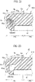
- An inclined surface facing downward and inclined downward toward the rear is formed at a front portion of the pad material 41A.
- An inclined surface facing upward and inclined downward toward the rear at the same angle as the inclined surface at the front portion of the pad material 41A is formed at a rear portion of the pad material 46.
- the inclined surface at the front portion of the pad material 41A and the inclined surface at the rear portion of the pad material 46 face each other and are in contact with each other.
- a parting line PL along which both pad materials 41A and 46 face and contact each other is extended from around the boundary between the lower posterior thigh contact portion PSc 1 and the posterior knee contact portion PSc 2 and is inclined downward toward the rear.
- the configuration is such that the thickness of the front portion of the pad material 41A changes to be smaller toward the front and that the thickness of the rear portion of the pad member 46 changes to be smaller toward the rear (or to be larger toward the bottom).
- the upward support reaction force fb 1 is obtained in a rear side of the front portion of the pad material 41A while the upward support reaction force fb 2 smaller than the upward support reaction force fb 1 is obtained in a front side of the front portion, due to the change in the thickness of the front portion.
- the forward support reaction force fc 1 is obtained from the posterior lower leg contact portion PSc 3 while the forward support reaction force fc 2 slightly greater than the forward support reaction force fc 1 is obtained from the posterior knee contact portion PSc 2 , due to the change, in the front-rear direction, in the thickness of the rear portion of the pad material 46.
- the above reaction force characteristics of the low stiffness region PSc are obtained by: forming the front part 2f of the seat cushion 2 by using the pad material 46 having a smaller spring constant than the pad material 41A used in the rear part 2g; and extending the parting line PL, along which the pad material 46 of the front part 2f of the seat cushion 2 and the pad material 41A of the rear part 2g face and contact each other, from around the boundary between the lower posterior thigh contact portion PSc 1 and the posterior knee contact portion PSc 2 and inclining the parting line PL downward toward the rear.
- reaction force characteristics similar to the second modified example can be imparted easily to the low stiffness region PSc of the front part 2f of the seat cushion 2 by changing the shapes of the connected portions of the pad material 41A and the pad material 46.
- the change in the support reaction forces in the range from the lower posterior thigh contact portion PSc 1 to the posterior knee contact portion PSc 2 can be made gentler by extending the parting line PL from around the boundary between the lower posterior thigh contact portion PSc 1 and the posterior knee contact portion PSc 2 and inclining the parting line PL downward toward the rear.
- the seating comfort in the range from the lower posterior thighs to the posterior knees of the occupant D can be improved further, thereby making it possible to further improve the seating quality.
- the front part 2f of the seat cushion 2 is formed by the single pad material 46.
- the reaction force characteristics of the low stiffness region PSc can be obtained advantageously in terms of cost.
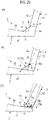
- Fig. 20 shows a fourth modified example of this embodiment.
- a single pad material 46 similar to that in the third modified example is used as the pad material 41B used in the low stiffness region PSc of the front part 2f of the seat cushion 2.
- a load receiving member 48 projecting upward is arranged in the low stiffness region PSc on a front portion of the seat cushion base member 47.
- the load receiving member 48 is made of an appropriate synthetic resin material or light metal material formed into a substantially channel cross-sectional shape and is disposed within the low stiffness region PSc in front of the boundary between the high stiffness region PHc and the low stiffness region PSc.
- An upper wall and a front wall of the load receiving member 48 are formed as suitably inclined surfaces.
- inclination of the upper wall of the load receiving member 48 is used to adjust the thickness, in the vertical direction, of the pad material 46 on an upper surface side of the load receiving member 48.
- inclination of the front wall of the load receiving member 48 is used to adjust the thickness, in the front-rear direction, of the pad material 46 on a front surface side of the load receiving member 48.
- the upward support reaction force fb 1 is obtained in a rear side of the pad material 46 while the upward support reaction force fb 2 smaller than the upward support reaction force fb 1 is obtained in a front side of the pad material 46, due to the adjustment of the thickness of the pad material 46 in the vertical direction.
- the forward support reaction force fc 1 is obtained from the posterior lower leg contact portion PSc 3 while the forward support reaction force fc 2 slightly greater than the forward support reaction force fc 1 is obtained from the posterior knee contact portion PSc 2 , due to the adjustment of the thickness of the pad material 46 in the front-rear direction.
- the above-described reaction force characteristics of the low stiffness region PSc are obtained by: forming the front part 2f of the seat cushion 2 by using the pad material 46 with a smaller spring constant than the pad material 41A used in the rear part 2g; arranging the upwardly projecting load receiving member 48 in the low stiffness region PSc on the front portion of the seat cushion base member 47; and adjusting the thickness of the pad material 46 of the front part 2f of the seat cushion 2 on the upper surface side and the front surface side of the load receiving member 48.
- the thickness of the pad material 46 can be adjusted by appropriately adjusting the shape of the load receiving member 48.
- the change in the support reaction forces in the range from the lower posterior thigh contact portion PSc 1 to the posterior knee contact portion PSc 2 can be adjusted freely, thereby making it possible to further improve the seating comfort in the range from the lower posterior thighs to the posterior knees of the occupant D.
- Fig. 21 shows a fifth modified example of this embodiment.
- a spring mechanism 49 capable of retreating in response to a seating load applied from the front, i.e. a load from the posterior lower legs is arranged on the front surface of the load receiving member 48 in the fourth modified example.
- the spring mechanism 49 includes: a movable plate 49a disposed facing the region of the posterior lower leg contact portion PSc 3 ; an advance-retreat guide 49 for the movable plate 49a provided on a front surface of the load receiving member 48; and a set spring 49c elastically set therebetween.
- the upward support reaction force fb 1 is obtained in the rear side of the pad material 46 while the upward support reaction force fb 2 smaller than the upward support reaction force fb 1 is obtained in the front side of the pad material 46, due to the adjustment of the thickness of the pad material 46 in the vertical direction.
- the forward support reaction force fc 1 is obtained by the spring mechanism 49 which retreats in response to a load from the posterior lower legs.
- the forward support reaction force fc 1 slightly greater than the support reaction force obtained by the adjustment of the thickness of the pad material 46.
- the above-described reaction force characteristics of the low stiffness region PSc are obtained by: forming the front part 2f of the seat cushion 2 by using the pad material 46 with a smaller spring constant than the pad material 41A used in the rear part 2g; arranging the upwardly projecting load receiving member 48 in the low stiffness region PSc on the front portion of the seat cushion base member 47; adjusting the thickness of the pad material 46 of the front part 2f of the seat cushion 2 on the upper surface side and the front surface side of the load receiving member 48; and providing, on the front surface of the load receiving member 48, the spring mechanism 49 capable of retreating in response to a seating load applied from the front.
- the spring constant of the spring mechanism 49 by appropriately adjusting the spring constant of the spring mechanism 49, it is possible to obtain a greater support reaction force than the support reaction obtained by simply adjusting the thickness of the pad material 46. Accordingly, the change in the support reaction forces in the range from the lower posterior thigh contact portion PSc 1 to the posterior knee contact portion PSc 2 can be adjusted more freely.
- Figs. 22 and 23 show other modified examples of the cushion pad 41.
- both of the modified examples shown in Figs. 22 and 23 use, as the cushion pad 41, a single pad material 41A set to have a standard spring constant required for the aforementioned general vehicle seat cushion. Moreover, the low stiffness region PSc is formed in the front part 2f of the seat cushion 2 with a hollow portion(s) 50 provided in a front part of the pad material 41A, while the rear part 2g is set as the high stiffness region PHc.
- multiple vertical slits 50A extending in the vehicle width direction are provided side by side in the front-rear direction in the region of the posterior lower leg contact portion PSc 3 of the pad material 41A to reduce the hardness of the front part of the pad material 41A and thereby form the low stiffness region PSc.
- the vertical slits 50A are designed to change the hardness of the pad material 41A in the vertical direction and the front-rear direction through adjustment of their lengths, positions in the vertical direction and the like.
- the lengths, positions in the vertical direction and the like of the vertical slits 50A are adjusted so as to obtain the forward support reaction force fc 1 from the posterior lower leg contact portion PSc 3 and obtain the forward support reaction force fc 2 slightly greater than the forward support reaction force fc 1 from the posterior knee contact portion PSc 2 .
- the vertical slits 50A extend to a middle portion of the pad material in the front side of the lower posterior thigh contact portion PSc 1 .
- the upward support reaction force fb 1 which is uniquely determined by the spring constant of the pad material 41A;
- the front side is the upward support reaction force fb 2 which is slightly smaller than the upward support reaction force fb 1 .
- the multiple vertical slits 50A extending in the vehicle width direction are provided side by side in the front-rear direction in the region of the posterior lower leg contact portion PSc 3 of the pad material 41A.
- the cushion pad 41 can be formed of the single pad material 41A in this modified example, the above-described reaction force characteristics can be obtained advantageously in terms of cost.
- a cavity 50B is provided along the vehicle width direction in the region of the posterior lower leg contact portion PSc 3 of the pad material 41A to reduce the hardness of the front part of the pad material 41A and thereby form the low stiffness region PSc.
- the cavity 50B is designed to change the hardness of the pad material 41A in the vertical direction and the front-rear direction through adjustment of its cross-sectional shape, cross-sectional area, positions in the vertical and front-rear directions and the like.
- the cross-sectional shape, cross-sectional area, positions in the vertical and front-rear directions and the like of the cavity 50B are adjusted so as to obtain the upward support reaction forces fb 1 and fb 2 from the lower posterior thigh contact portion PSc 1 and obtain the forward support reaction forces fc 1 and fc 2 from the posterior lower leg contact portion PSc 3 and the posterior knee contact portion PSc 2 .
- the cavity 50B is provided along the vehicle width direction in the region of the posterior lower leg contact portion PSc 3 of the pad material 41A.
- the cushion pad 41 can be formed of the single pad material 41A in this modified example as well, the reaction force characteristics can be obtained advantageously in terms of cost.
- the structure of the cushion pad is not limited to the instances shown in this embodiment and its modified examples.
- the structure of the cushion pad only needs to be a design in which the low stiffness region PSc is present in the front part 2f of the seat cushion 2 and which offers reaction force characteristics imparting such directional properties that the support reaction forces thereof are large in the vertical direction and small in the front-rear direction.
- the seat cushion 2 is formed by using the single pad material 41A, and the hollow portion(s) 50 (50A, 50B) is provided in the front part of the pad material 41A to form the low stiffness region PSc of the cushion 2 and also to obtain the above-described reaction force characteristics in the low stiffness region PSc.
- the hollow portion(s) 50 provided in the pad material 41A, it is possible to set more freely the change in the support reaction forces in the range from the lower posterior thigh contact portion PSc 1 to the posterior knee contact portion PSc 2 .
- a vehicle seat 1 for rear seat according to a fourth embodiment of the present invention.
- the vehicle seat 1 of this embodiment includes a front part 2f of a seat cushion 2 as a low stiffness region PSc and a rear part 2g thereof as a high stiffness region PHc.
- the low stiffness region PSc of the seat cushion 2 is given reaction force characteristics of having a large support reaction force fb for a seating load applied from the above and a small support reaction force fc for a seating load applied from the front.
- a low stiffness region PSb having a small support reaction force fa 1 for an occupant D is set in the center portion in the vertical direction thereof.
- High stiffness regions PHb 1 and PHb 2 each having a large support reaction force fa 2 for the occupant D are set, adjacent to the low stiffness region PSb in the vertical direction, in upper and lower portions of the seat back 3.
- the seat back 3 is provided with a stiffness distribution having different reaction force characteristics in the vertical direction.
- a backrest surface 3a of the seat back 3 can be bent in the middle at the foregoing low stiffness region PSb at any of various middle bend angles, in a shallow V shape in the side view, for example, according to a backrest load of the occupant D.
- the high stiffness region PHb 1 in the upper portion of the seat back 3 is formed to approximately correspond to a chest Da of the occupant D
- the high stiffness region PHb 2 in the lower portion thereof is formed to approximately correspond to a pelvis Dc of the occupant D
- the low stiffness region PSb in the center portion of the seat back is formed to have a required vertical width dimension having its center at a body part of the occupant D corresponding to the vicinity of the joints of the chest Da and a waist Db, i.e., the tenth thoracic vertebra Da 1 to the twelfth thoracic vertebra Da 2 .
- the backrest surface 3a can be bent in the middle at a vertical center position PS 0 of the low stiffness region PSb as a bend point BP, in response to the backrest load.
- the support reaction force fa gets larger in the downward direction from the center to the lower end portion of the backrest surface 3a.
- the pelvis Dc can be particularly supported.
- the support reaction force fa gets larger in the upward direction from the center to the upper end portion of the backrest surface 3a.
- the chest Da can be firmly supported.
- the fourth embodiment is an example where the stiffness distribution in the second embodiment is imparted to the seat back 3 in the vehicle seat 1 of the first embodiment, and the reaction force characteristics in the third embodiment are imparted to the front part 2f of the seat cushion 2.
- the vehicle seat 1 includes the front part 2f of the seat cushion 2 as the low stiffness region PSc and the rear part 2g thereof as the high stiffness region PHc.
- an HP guide function, a space expansion function and an HP shift prevention function can be exerted for the series of actions taken by the occupant D for seating described in the first embodiment.
- the vehicle seat 1 includes the front part 2f of the seat cushion 2 as the low stiffness region PSc and the rear part 2g thereof as the high stiffness region PHc.
- This structure suppresses the resistance to the series of actions (particularly, backward movement and turnaround of the occupant D on the seat cushion 2) taken by the occupant D after getting into the rear seat until the completion of the turnaround, thereby easily guiding a hip point HP of the occupant D to an optimum position.
- the low stiffness region PSc of the seat cushion 2 is given the reaction force characteristics of having the large support reaction force fb for the seating load applied from the above and the small support reaction force fc for the seating load applied from the front.
- the front part 2f is flexibly deformed in response to the seating load applied from the front due to contact of the knees or the lower legs therewith.
- the resistance to the movement or turnaround of the occupant D on a seating surface 2a is surely reduced.
- the stiffness distribution including the high stiffness region PHb 1 , the low stiffness region PSb and the high stiffness region PHb 2 , which have different reaction force characteristics in the vertical direction of the seat back 3, is imparted.
- the backrest surface 3a of the seat back 3 can be bent in the middle according to the backrest load of the occupant D. Accordingly, the back of the occupant D leaning back on the seat back 3 is gently curved to protrude backward. As a result, the occupant D can more easily move the hip backward, and guide the hip point HP to the optimum position.
- the backrest surface 3a of the seat back 3 is bent in the middle at the middle bend angle which allows a comfortable posture most suitable for the body size of the occupant D by the automatic adjustment function for the middle bend angle described in the second embodiment.
- the occupant D can more easily move the hip backward, and surely guide the hip point HP to the optimum position.
- the occupant D may adjust the hip position by pushing the floor surface with his/her legs while pressing the back against the backrest surface 3a of the seat back 3.
- a reaction force from the high stiffness region PHb 1 in the upper portion of the backrest surface 3a acts on the back of the occupant D.
- the stiffness distribution having different reaction force characteristics in the vertical direction of the seat back 3 is imparted.
- the backrest surface 3a of the seat back 3 can be bent in the middle according to the backrest load of the occupant D.
- the vehicle seat 1 can handle variations in the body size of the occupant D.
- the low stiffness region PSc is provided in the front part 2f of the seat cushion 2, and the low stiffness region PSc can be deformed with a relatively small load.
- the occupant D can position the hip further backward on the seating surface 2a.
- an actual foot space of the vehicle seat 1 is expanded.
- the occupant D may shift the position of the hip point HP with the load of the hip reduced by pushing the floor surface with the legs while pressing the back against the backrest surface 3a of the seat back 3.
- the low stiffness region PSc is provided in the front part 2f of the seat cushion 2, and the low stiffness region PSc is deformed with a relatively small load.
- the occupant D can easily stretch his/her legs when pushing the floor surface with the legs.
- the low stiffness region PSc of the seat cushion 2 is given the reaction force characteristics of having the large support reaction force fb for the seating load applied from the above and the small support reaction force fc for the seating load applied from the front.
- the downward sinking amount of the front part 2f of the seat cushion 2 is suppressed, thereby stably supporting the lower posterior thighs.
- the front part 2f is flexibly deformed in response to the seating load applied from the front.
- the foot space can be surely secured.
- the high stiffness region PHc is provided in the rear part 2g of the seat cushion 2, and the resistance to the backward movement of the occupant D is suppressed.
- the hip of the occupant D is readily guided backward along the seating surface 2a, and the occupant D is readily guided to a knee-bent posture.
- a knee room positioned in front of the knees of the occupant D is secured at an early stage after the start of the seating action. As a result, an effect that is equivalent to actually expanding a knee room can be achieved.
- the stiffness distribution having different reaction force characteristics in the vertical direction of the seat back 3 is imparted. Accordingly, the backrest surface 3a of the seat back 3 can be bent in the middle according to the backrest load of the occupant D. Thus, the size of the space in front of the backrest surface 3a can be changed automatically based on the body size of the occupant D. In other words, the backrest surface 3a receives the back of the occupant D arriving after moving backward along with the movement of the hip on the seating surface 2a, while bending by a middle bend amount according to the body size of the occupant D.
- the backrest surface 3a does not hinder the backward movement of the hip.
- smooth backward movement of the hip can be more surely realized.
- the knee room of the occupant D is secured at an earlier stage after the start of the seating action, and an actual knee room expansion effect can be more surely achieved.
- the backrest surface 3a of the seat back 3 is bent in the middle at the middle bend angle which allows a comfortable posture most suitable for the body size of the occupant D by the automatic adjustment function for the middle bend angle described in the second embodiment. Accordingly, the occupant D can obtain a comfortable posture most suitable for his/her body size just by leaning back on the seat back 3. Thus, a feeling of spaciousness the occupant D experiences, regardless of the body size, is improved.
- the vehicle seat 1 can handle variations in the body side of the occupant D.
- the vehicle seat 1 includes the front part 2f of the seat cushion 2 as the low stiffness region PSc and the rear part 2g thereof as the high stiffness region PHc, and the stiffness of the cushion pad below the hip of the occupant D is higher.
- the stiffness of the cushion pad below the hip of the occupant D is higher.
- the occupant D is in the knee-bent posture while seated in the vehicle seat 1, and the gravity center thereof is closer to the back side.
- the hip of the occupant D tends to slide further backward.
- the high stiffness region PHc is provided in the rear part 2g of the seat cushion 2, thus reducing the resistance to the backward movement of the occupant D on the seating surface 2a. Accordingly, the hip of the occupant D is likely to slide further backward.
- the vehicle seat 1 includes the seat back 3, and the hip trying to move further backward is received from the back by the seat back 3.
- the hip of the occupant D is stably held at a position where the backward sliding force and the forward pressing force of the seat back 3 are balanced with each other.
- the positional shift in the hip point HP is more surely prevented.
- the high stiffness region PHb 2 having a large support reaction force fa 2 for the occupant D is set in the lower portion of the seat back 3.
- the hip trying is received more surely from the back by the high stiffness region PHb 2 .
- the positional shift in the hip point HP can be more surely prevented.
- the low stiffness region PSc of the seat cushion 2 is given the reaction force characteristics of having the large support reaction force fb for the seating load applied from the above and the small support reaction force fc for the seating load applied from the front.
- the downward sinking amount of the front part 2f of the seat cushion 2 is suppressed, thereby more stably supporting the lower posterior thighs.
- a reaction force for the seating load applied from the front is small.
- the positional shift in the hip point HP can be more surely prevented.
- the seating surface 2a of the vehicle seat 1 as described above, a rearward inclined surface is formed in front of a region right below the hip by a load applied therefrom in seating.
- the seating surface 2a has a maximum deformation part LP between the rearward inclined surface and the backrest surface 3a of the seat back 3.
- the vehicle seat 1 according to this embodiment supports the pelvis Dc of the occupant D with the maximum deformation part LP, and thus the pelvis Dc is stably held in a constant posture. Thus, the positional shift in the hip point HP is more surely prevented.
- the stiffness distribution having different reaction force characteristics in the vertical direction of the seat back is imparted.
- the backrest surface 3a of the seat back 3 can be bent in the middle according to the backrest load of the occupant D. Accordingly, a downward component is added to the reaction force acting on the back of the occupant D from the high stiffness region PHb 1 of the backrest surface 3a.
- the downward component to press the hip of the occupant D in a seated state against the seating surface 2a.
- the positional shift in the hip point HP of the occupant in the seated state is more surely prevented.
- the vehicle seat 1 can handle variations in the body size of the occupant D.
- the vehicle seat 1 of the fourth embodiment is configured as follows.
- the low stiffness region PSb having a small support reaction force fa 1 of the occupant D is set in the vertical center portion of the seat back 3.
- the high stiffness regions PHb 1 and PHb 2 having a large support reaction force fa 2 of the occupant D are set in the upper and lower portions of the seat back 3 so as to be adjacent to the low stiffness region PSb.
- the stiffness distribution having different reaction force characteristics in the vertical direction of the seat back 3 is imparted. Accordingly, the backrest surface 3a of the seat back 3 can be bent in the middle at the low stiffness region PSb at any of various middle bend angles.
- vehicle seat 1 handles variations in the body size of the occupant D regardless of whether the occupant D is large or small. Accordingly, the HP guide function, the space expansion function and the HP shift prevention function can be simultaneously achieved more surely during the series of actions taken by the occupant D for seating in the vehicle seat 1.
- the fourth embodiment can, of course, achieve operations and effects similar to the operations and effects of the first to third embodiments, such as the automatic adjustment mechanism for the middle bend angle of the seat back. However, description thereof is omitted herein to avoid redundancy.
- the HP guide function, the space expansion function and the HP shift prevention function can be simultaneously achieved during the series of actions taken by the occupant D for seating in the vehicle seat 1, by imparting a predetermined stiffness distribution to the seat cushion 2 and/or the seat back 3.
- the above three functions can be simultaneous achieved also by: imparting the above-mentioned predetermined stiffness distribution to the seat cushion 2 and/or the seat back 3; and then adjusting some other mechanical properties (stiffness, friction coefficient, shape, etc.) of the seat cushion 2 and/or the seat back 3.
- the front part 2f of the seat cushion 2 is set as the low stiffness region PSc and the rear part 2g thereof as the high stiffness region PHc, as in the case of the first embodiment, and then adjust some other mechanical properties of the seat cushion 2 and/or the seat back 3.
- the seating surface 2a of the seat cushion 2 may be such that adjacent portions of the seating surface 2a differ from each other in at least one of stiffness, friction coefficient and shape.
- the backrest surface 3a of the seat back 3 may be such that adjacent portions of the backrest surface 3a differ from each other in at least one of stiffness, friction coefficient and shape.
- the contact region between the seating surface 2a and/or the backrest surface 3a and the occupant D moves over the seating surface 2a and/or the backrest surface 3a while continuously changing its contact area, along the series of actions by the occupant D for seating in the vehicle seat 1.
- the force acting on the occupant D from the contact region can be changed continuously or stepwise along the series of actions taken by the occupant D, for example.
- the mechanical properties of the seating surface 2a may be set so as to change continuously or stepwise over portions of the seating surface 2a adjacent to each other in the front-rear direction. In this way, it is possible to further improve the comfort the occupant D experiences while the hip of the occupant D is moving on the seating surface 2a in the front-rear direction, i.e. while the vehicle seat 1 is exerting the HP guide function.
- the mechanical properties of the backrest surface 3a may be set so as to change continuously or stepwise over portions of the backrest surface 3a adjacent to each other in the vertical direction.
- the mechanical properties of the seating surface 2a and/or the backrest surface 3a may be set so as to change continuously or stepwise over portions of the seating surface 2a and/or the backrest surface 3a adjacent to each other in the left-right direction. In this way, it is possible to further improve comfortability in seating and also to adjust hold performance on the hip and the chest Da.
- the following properties are possible as the mechanical properties of the seat cushion 2 and/or the seat back 3 to be adjusted, for example.
- the following combinations are possible as combinations of the properties to be adjusted.
- a case employing (e) (or (f)) on the assumption that the front part 2f of the seat cushion 2 is the low stiffness region PSc and that the rear part 2g thereof is the high stiffness region PHc is described below as a fifth embodiment, Moreover, a case employing a combination of (c) with the stiffness distribution of the seat cushion 2 is described as a sixth embodiment, and a case employing a combination of (c) and (d) is described as a modified example of the sixth embodiment.
- a case employing a combination of (e) with the stiffness distribution of the seat cushion 2 is described as a seventh embodiment, and a case employing a combination of (e) and (f) is described as a modified example of the seventh embodiment.
- a case employing a combination of the four properties (c) to (f) is described as an eighth embodiment.
- a vehicle seat 1 for rear seat according to a fifth embodiment of the present invention.
- This embodiment is an example in which an inclined surface 71 to be described below is provided in the vehicle seat 1 of the first embodiment.
- the vehicle seat 1 includes the inclined surface 71 configured to support the hip of an occupant D in a corner region ⁇ where a seating surface 2a of a seat cushion 2 and a backrest surface 3a of a seat back 3 are joined to each other.
- an intersection A between the inclined surface 71 and the seating surface 2a of the seat cushion 2 is set at a position slightly behind the ischial tuberosity Dc 1 in the pelvis Dc of the occupant D.
- an intersection B between the inclined surface 71 and the backrest surface 3a of the seat back 3 is set at a position corresponding to the vicinity of the sacrum Dc 2 in the pelvis Dc of the occupant D.
- a distance ⁇ 1 from an intersection C between an extended line of the seating surface 2a and an extended line of the backrest surface 3 a to the intersection A in a side view of the corner region ⁇ is preferably set to a value smaller than 1/6 of the length L 1 from the intersection C to a front end of the seat cushion 2 ( ⁇ 1 ⁇ L 1 /6).
- a distance ⁇ 2 from the intersection C to the intersection B is preferably set to a value smaller than 1/5 of the length L 2 from the intersection C to an upper end of the seat back 3 ( ⁇ 2 ⁇ L 2 /5).
- an inclination angle ⁇ 1 (angle of the inclined surface 71 to a horizontal plane) of the inclined surface 71 is set to be smaller than an inclination angle ⁇ 2 of the backrest surface 3a (angle of the backrest surface 3a to the horizontal plane).
- the vehicle seat 1 includes a front part 2f of the seat cushion 2 as a low stiffness region PSc and a rear part 2g thereof as a high stiffness region PHc.
- an HP guide function, a space expansion function, and an HP shift prevention function can be exerted for the series of actions taken by the occupant D for seating which is described in the first embodiment.
- the vehicle seat 1 includes the inclined surface 71 configured to support the hip of the occupant D in the corner region ⁇ where the seating surface 2a of the seat cushion 2 and the backrest surface 3 a of the seat back 3 are joined to each other.
- the hip of the occupant D comes into contact with the inclined surface 71 in the corner region ⁇ and is guided to the optimum position by the inclined surface 71. This prevents the position of the hip from varying every time the occupant D is seated.
- the vehicle seat 1 includes the inclined surface 71 configured to support the hip of the occupant D in the corner region ⁇ and the inclined surface 71 supports a back surface of the pelvis Dc of the occupant D.
- backward rotation of the pelvis Dc is suppressed even in a long-hour drive.
- This prevents reduction in a knee room in front of the knees, which might otherwise occur if the hip of the occupant D shifts forward and the occupant D loses the seating posture.
- the knee room in front of the knees is restricted to be small particularly in the rear seat.
- a large knee room can be secured by the effect of suppressing the frontward and a comfortable seating posture for the occupant D can be also obtained. Hence, fatigue of the occupant D can be reduced.
- the high stiffness region PHc is provided in the rear part 2g of the seat cushion 2, thereby reducing the resistance to the rearward movement of the occupant D on the seating surface 2a. Accordingly, the hip of the occupant D in the knee-bent posture tends to slide further rearward.
- the vehicle seat 1 according to this embodiment includes the inclined surface 71 configured to support the hip of the occupant D in the corner region ⁇ .
- the entire pelvis Dc of the hip which tends to move further rearward can be received from the rear side and surely supported by the inclined surface 71.
- a positional shift in the hip point HP can be more surely prevented.
- a rearward inclined surface is formed in front of a region right below the hip by the seating load.
- the seating surface 2a has a maximum deformation part LP between the rearward inclined surface and the backrest surface 3a of the seat back 3.
- the vehicle seat 1 according to this embodiment includes the inclined surface 71 configured to support the hip of the occupant D in the corner region ⁇ and the pelvis Dc of the occupant D is supported by the inclined surface 71 and the maximum deformation part LP. Accordingly, the pelvis Dc is stably held in a constant posture. As a result, the positional shift in the hip point HP is more surely prevented.
- the intersection A between the inclined surface 71 and the seating surface 2a of the seat cushion 2 is set at a position slightly behind the ischial tuberosity Dc 1 in the pelvis Dc of the occupant D. Accordingly, the hip of the occupant D can be prevented from being pushed forward by the inclined surface 71.
- the intersection B between the inclined surface 71 and the backrest surface 3a of the seat back 3 is set at the position corresponding to the vicinity of the sacrum Dc 2 in the pelvis Dc of the occupant D. Accordingly, the entire pelvis Dc can be surely supported by the inclined surface 71. This improves the effect of suppressing the frontward shift of the hip of the occupant D and the collapse of seating posture can be more surely prevented.
- the inclination angle of the inclined surface 71 is set to be smaller than the inclination angle of the backrest surface 3a. Accordingly, the inclined surface 71 surely acts on the pelvis Dc and the pelvis Dc of the occupant D is maintained at a posture rotated slightly backward. Hence, a comfortable seating posture for the occupant D is obtained and fatigue of the occupant D can be reduced.
- the vehicle seat 1 of the fifth embodiment includes the inclined surface 71 configured to support the hip of the occupant D in the corner region ⁇ where the seating surface 2a of the seat cushion 2 and the aforementioned backrest surface 3a of the seat back 3 are joined to each other. Accordingly, the function of guiding the hip of the occupant D to the optimum position and the frontward shift suppressing function of the pelvis supporting can be exerted more effectively and the HP guide function, the space expansion function, and the HP shift prevention function can be surely achieved during the series of actions taken by the occupant D for seating in the vehicle seat 1.
- the vehicle seat 1 of the fifth embodiment includes the inclined surface 71 configured to support the hip of the occupant D in the corner region ⁇ in addition to the configuration of the first embodiment described above. Accordingly, a stable seating posture having only a small collapse of the posture of the occupant D is achieved by the frontward shift suppressing function of the pelvis supporting by the inclined surface 71 and a good fatigue reducing effect can be thereby obtained.
- Fig. 28 shows a first modified example of this embodiment.
- the modified example is an example in which the inclined surface 71 of the embodiment is applied to the fourth embodiment.
- the front part 2f of the seat cushion 2 is set as the low stiffness region PSc and the rear part 2g is set as the high stiffness region PHc as in the case of the first embodiment.
- the low stiffness region PSc of the seat cushion 2 is given reaction force characteristics of having a large support reaction force fb for a seating load applied from the above and a small support reaction force fc for a seating load applied from the front..
- a low stiffness region PSb having a small support reaction force fa 1 for the occupant D is set in a vertical center portion of the seat back 3 and high stiffness regions PHb 1 and PHb 2 having a large support reaction force fa 2 for the occupant D are set, adjacent to the low stiffness region PSb in the vertical direction, in upper and lower portions of the seat back 3.
- a stiffness distribution in which the reaction force characteristics vary in the vertical direction of the seat back 3 is imparted.
- the backrest surface 3a of the seat back 3 can be bent in the middle at the low stiffness region PSb described above, at various middle bend angles, in a shallow V shape in the side view, for example, according to backrest load of the occupant D.
- the high stiffness region PHb 1 in the upper portion of the seat back 3 is formed to approximately correspond to the chest Da of the occupant D
- the high stiffness region PHb 2 in the lower portion is formed to approximately correspond to the pelvis Dc of the occupant D.
- the low stiffness region PSb in the center portion of the seat back 3 is formed to have a required vertical width around a body part of the occupant D corresponding to the vicinity of the joints of the chest Da and the waist Db, i.e., the tenth thoracic vertebra Da 1 to the twelfth thoracic vertebra Da 2 .
- the backrest surface 3a can be bent in the middle with the vertical center position PS 0 of the low stiffness region PSb as a bend point BP, with respect to the backrest load.
- the support reaction force fa gets larger in the downward direction from the center to the lower end portion of the backrest surface 3a.
- the pelvis Dc can be particularly supported.
- the support reaction force fa gets larger in the upward direction from the center to the upper end portion of the backrest surface 3a.
- the chest Da can be firmly supported.
- the modified example has a configuration similar to those of the first to fifth embodiments described above, the operations and effects of these embodiments can be obtained simultaneously. Moreover, in the modified example, synergy of bending of the backrest surface 3a of the seat back 3 in the middle at an optimum angle according to the body size of the occupant D and the effect of suppressing the frontward of the hip from the optimum position on the seat cushion 2 is obtained in addition the operations and effects of the embodiments described above. Accordingly, it is possible to further obtain an effect of achieving seating stability and a comfortable seating quality regardless of whether the occupant is a small-build person or a large-build person.
- Fig. 29 shows examples of configurations for the inclined surface 71 described above.
- Part (A) of Fig. 29 shows an example in which an inclination fulcrum P of the seat back 3 with respect to the seat cushion 2 is above the intersection B.
- a protruding portion 2A which has substantially the same thickness and width as the lower end of the seat back 3 and which protrudes upward is formed integral with a rear end portion of the seat cushion 2.
- the inclined surface 71 is formed by adjusting the shape of a pad material 41A on a front surface side of the protruding portion 2A.
- the inclined surface 71 may be formed of a protruding portion A formed integral with either the seat cushion 2 or the seat back 3.
- the inclined surface 71 can be formed by shaping either the pad material 41A of the seat cushion 2 or a pad material (cushion pad) 15 of the seat back 3. Since the inclined surface 71 with relatively higher stiffness can be obtained in this configuration, the function of guiding the hip of the occupant D to the optimum position and the frontward shift suppressing function of the pelvis supporting can be exerted more effectively. Moreover, no major changes in structure and design of the seat cushion 2 and the seat back 3 are made in this configuration and the obtaining of the inclined surface 71 can be achieved advantageously in terms of cost.
- Parts (B) and (C) of Fig. 29 each show an example in which the inclination fulcrum P is below the intersection B.
- the inclined surface 71 is formed of an elastic band-shaped member 72 laid between the seating surface 2a of the seat cushion 2 and the backrest surface 3a of the seat back 3 across the corner region ⁇ .
- An end portion of the elastic band-shaped member 72 on the intersection A side is tied and fixed by effective use of cushion wires in the seat cushion 2 and is stitched at a penetrating lead-out portion (intersection A) of the seating surface 2a.
- the elastic band-shaped member 72 penetrates the backrest surface 3a of the seat back 3 through a slit 73 provided at the intersection B and the other end portion of the elastic band-shaped member 72 is tied and fixed to the inclination fulcrum P.
- An intermediate portion of the elastic band-shaped member 72 is slidably supported near the slit 73 (near the intersection B) by effective use of a lower pad supporting member 16L of a pad supporting member 16 for example.
- a lower pad supporting member 16L of a pad supporting member 16 for example.
- the inclined surface 71 is formed of the elastic band-shaped member 72 laid between the seating surface 2a of the seat cushion 2 and the backrest surface 3a of the seat back 3 across the corner region ⁇ .
- the stiffness of the inclined surface 71 can be controlled by adjusting the tension of the elastic band-shaped member 72. Accordingly, the function of guiding the hip of the occupant D to the optimum position and the frontward shift suppressing function of the pelvis supporting can be controlled easily on demand. Thus, it is possible to exert these functions more effectively.
- no major changes in structure and design of the seat cushion 2 and the seat back 3 are made in this configuration and the obtaining of the inclined surface 71 can be achieved advantageously in terms of cost.
- the inclined surface 71 is formed by disposing a shape retaining member 74 near a surface of the inclined surface 71 of the backrest surface 3a.
- the shape retaining member 74 is made of an appropriate synthetic resin and is formed in a wedge shape in the side view.
- the shape retaining member 74 can be moved parallel in the front-rear direction by moving means 75 which moves along with the inclination of the seat back 3.
- the moving means 75 is a rack-and-pinion mechanism including a pinion 75a arranged eccentric to the inclination fulcrum P and a rack 75b provided continuously with the shape retaining member 74 and meshing with the pinion 75a.
- the inclined surface 71 is formed by disposing the shape retaining member 74 near the surface of the inclined surface 71 of the backrest surface 3a and the shape retaining member 7 can be moved parallel in the front-rear direction by the moving means 75 which moves along with the inclination of the seat back 3. Accordingly, the inclined surface 71 can be disposed at the optimum position in the corner region ⁇ according to the rearward inclination angle of the seat back 3. Thus, both of the inclination adjustment of the seat back 3 in a larger angle range and the optimum arrangement of the inclined surface 71 can be achieved.
- the rack-and-pinion mechanism described above is used as the moving means 75 in this example, the moving means 75 is not limited to this and a wire mechanism having a self-return function, a link mechanism, or the like may be selectively used.
- the inclined surface 71 may be applied not only to the first embodiment but also in combination with any of the second to fourth embodiments and the modified examples thereof. In each of examples of these combinations, it is possible to simultaneously obtain the effects of the embodiments and the like included in the combination.
- a vehicle seat 1 for rear seat according to a sixth embodiment not in accordance with the present invention.
- the embodiment is an example in which a friction coefficient distribution described below is imparted to a seat cushion 2 in the vehicle seat 1 of the first embodiment.
- HF HF 1 , HF 2 , HF 3 , and HF 4
- LF LF 1 , LF 2 , LF 3 , and LF 4
- a seating surface 2a of the seat cushion 2 is configured such that, in a portion (hereinafter referred to as front portion) R1 located in front of a maximum deformation part LP in seating, a friction coefficient LF 1 against sliding from the front to the rear is set to be lower than a friction coefficient HF 1 against sliding from the rear to the front (LF 1 ⁇ HF 1 ). Moreover, in a portion (hereinafter referred to as rear portion) R2 located behind the maximum deformation part LP, a friction coefficient LF 2 against sliding from the rear to the front is set to be lower than a friction coefficient HF 2 against sliding from the front to the rear (LF 2 ⁇ HF 2 ).
- the magnitude of the friction coefficient of a supporting surface can be determined based on a resistance force obtained as follows. For example, a material generally used for clothing of an occupant D is cut into predetermined shape and size and the cut material is made to slide on the supporting surface while being pressed against the supporting surface at a predetermined pressure. It can be said that a surface with small resistance force at this time has a low friction coefficient and a surface with large resistance force at this time has a high friction coefficient.
- the vehicle seat 1 includes a front part 2f of the seat cushion 2 as a low stiffness region PSc and a rear part 2g thereof as the high stiffness region PHc.
- an HP guide function, a space expansion function, and an HP shift prevention function can be exerted for the series of actions taken by the occupant D for seating which is described in the first embodiment.
- the seating surface 2a of the seat cushion 2 is configured such that the friction coefficient LF 1 against sliding from the front to the rear is set to be lower than the friction coefficient HF 1 against sliding from the rear to the front in the front portion R1 while the friction coefficient LF 2 against sliding from the rear to the front is set to be lower than a friction coefficient HF 2 against sliding from the front to the rear in the rear portion R2. Accordingly, resistance against movement of the hip of the occupant D toward an optimum position (rearward movement in a region in front of the maximum deformation part LP and frontward movement in a region behind the maximum deformation part LP) is further suppressed and the hip point HP of the occupant D can be easily guided to the optimum position. Thus, the HP guide function can be more surely exerted for series of actions taken by the occupant D for seating.
- the seating surface 2a of the seat cushion 2 is configured such that the friction coefficient LF 1 against sliding from the front to the rear is set to be lower than the friction coefficient HF 1 against sliding from the rear to the front in the front portion R1. Accordingly, the resistance against movement of the hip of the occupant D toward the optimum position (typically rearward movement) is further suppressed and the hip of the occupant D further tends to slide backward. Thus, the hip of the occupant D is readily guided to the optimum position along the seating surface 2a after the start of the action for seating and a knee room of the occupant D is secured at an early stage after the start of the action for seating. As a result, an effect of substantial expansion of the knee room is surely obtained.
- the seating surface 2a of the seat cushion 2 is configured such that the friction coefficient LF 1 against sliding from the front to the rear is set to be lower than the friction coefficient HF 1 against sliding from the rear to the front in the front portion R1 while the friction coefficient LF 2 against sliding from the rear to the front is set to be lower than the friction coefficient HF 2 against sliding from the front to the rear in the rear portion R2. Accordingly, resistance against frontward or rearward movement from the optimum position is further increased. Thus, the positional shift of the hip after the placement of the hip at the optimum position is more surely prevented.
- the seating surface 2a of the seat cushion 2 is configured such that the friction coefficient LF 1 against sliding from the front to the rear is set to be lower than the friction coefficient HF 1 against sliding from the rear to the front in the front portion R1 in front of the maximum deformation part LP in seating while the friction coefficient LF 2 against sliding from the rear to the front is set to be lower than the friction coefficient HF 2 against sliding from the front to the rear in the rear portion R2 behind the maximum deformation part LP in seating.
- the function of guiding the hip of the occupant D to the optimum position and the function of maintaining the seating posture by the seating surface 2a are more effectively exerted and the HP guide function, the space expansion function, and the HP shift prevention function can be more surely achieved during the series of actions taken by the occupant D for seating in the vehicle seat 1.
- Fig. 31 shows a first modified example of this embodiment.
- the modified example is an example in which a seat back 3 is configured to be bendable in the middle as in the case of the second embodiment, in the vehicle seat 1 according to the sixth embodiment.
- a friction coefficient HF 3 of a portion portion R3 above a bend point BP (hereinafter referred to as, upper portion R3)) corresponding to the chest Da of the occupant D is set to be higher than a friction coefficient LF 4 of a portion (portion R4 below a bend point BP (hereinafter referred to as, lower portion R4)) below this portion (upper portion R3) (LF 4 ⁇ HF 3 ).
- the friction coefficient HF 3 of the portion (upper portion R3) of the backrest surface 3a corresponding to the chest Da is set to be higher. This allows the relatively heavy chest Da to be firmly supported with the seat back 3. Accordingly, the muscle burden of the occupant D can be reduced. This can prevent collapse of seating posture of the occupant D and reduce fatigue of the occupant D.
- the friction coefficient HF 4 of the portion (upper portion R4) below the portion (upper portion R3) corresponding to the chest Da is set to be lower. This improves sliding characteristics of the backrest surface 3a and the ischium of the occupant D tends to slide down to the maximum deformation part LP of the seat cushion 2.
- the function of guiding the hip point HP to the optimum position can be further exerted.
- the friction coefficients LF 4 and HF 3 of the backrest surface 3a are different from each other in the upper portion and the lower portion with the bend point BP being the boundary in the example shown in Fig. 31
- the position where the friction coefficient changes is not limited to the bend point BP. Effects similar to those described above can be exerted as long as the friction coefficient of the portion of the backrest surface 3a corresponding to the chest Da of the occupant D is set to be higher than the friction coefficient of the portion therebelow.
- Fig. 32 shows a second modified example of the embodiment.
- the modified example is an example in which a raised fabric is used as a seat surface material 81 in the first modified example and the raised direction of the fabric is changed depending on the position on the seating surface 2a of the seat cushion 2 or the position on the backrest surface 3a of the seat back 3.
- the seat surface material 81 is attached with an adhesion layer 83 to a surface of a surface urethane layer 82 provided in an outermost surface layer of a cushion pad 41 of the seat cushion 2 or a cushion pad 15 of the seat back 3.
- the raised direction is set to an upward direction in the upper portion R3 above the bend point BP of the backrest surface 3a and a friction coefficient LF 3 against sliding from the bottom to the top is thereby set to be lower than a friction coefficient HF 3 against sliding from the top to the bottom in the upper portion R3 (LF 3 ⁇ HF 3 ).
- the raised direction is set to a downward direction in the lower portion R4 below the bend point BP of the backrest surface 3a and a friction coefficient LF 4 against sliding from the top to the bottom is thereby set to be lower than a friction coefficient HF 4 against sliding from the bottom to the top in the lower portion R4 (LF 4 ⁇ HF 4 ).
- the raised direction is set to a frontward direction in the front portion R1 in front of the maximum deformation part LP of the seating surface 2a of the seat cushion 2 while the raised direction is set to a rearward direction in the rear portion R2 behind the maximum deformation part LP.
- the friction coefficient LF 1 against sliding from the front to the rear is set to be lower than the friction coefficient HF 1 against sliding from the rear to the front in the front portion R1 (LF 1 ⁇ HF 1 ) while the friction coefficient LF 2 against sliding from the rear to the front is set to be lower than the friction coefficient HF 2 against sliding from the front to the rear in the rear portion R2 (LF 2 ⁇ HF 2 ).
- the seat surface material 81 is particularly not limited as long as it is a raised material.
- the seat surface material 81 may be, in addition to the fabric, materials such as synthetic leather, artificial leather, or a combination of these materials.
- the same seat surface material 81 can be used for the entire vehicle seat 1. Accordingly, the vehicle seat 1 can have a uniform appearance. Moreover, similar effects as those of the first modified example of the sixth embodiment can be achieved at a low cost.
- Fig. 33 shows a third modified example of the embodiment.
- the seating surface 2a of the seat cushion 2 is configured such that a surface layer of the front portion R1 in front of the maximum deformation part LP in seating is set to be set to be softer than (deform at a greater degree to the same pressure) a surface layer of the rear portion R2 behind the maximum deformation part LP.
- the stiffness SSc of the surface layer of the front portion R1 is set to be lower than the stiffness HSc of the surface layer of the rear portion R2 (SSc ⁇ HSc).
- the surface layer of the vehicle seat 1 is elastically deformed by a load pressure applied when the occupant D is seated.
- the surface layer of the front portion R1 in front of the maximum deformation part LP is set to be softer (deform at a greater degree to the same pressure). Accordingly, a forward positional shift of the hip in the seated state can be prevented.
- the surface layer of the rear portion R2 behind the maximum deformation part LP is set to be stiffer (deform at a smaller degree to the same pressure). Accordingly, the ischium of the occupant D tends to slide down to the maximum deformation part LP of the seat cushion 2.
- the function of guiding the hip point HP to the optimum position can be further exerted.
- the thickness of each of the surface layers is appropriately adjusted depending on the body size of the occupant D and the stiffness of the pad material (the cushion pad 41 of the seat cushion 2 in the modified example) supporting the surface layer, which are design conditions, and is thus not particularly limited. However, it is preferable that the thickness is within a range of 5 mm to 30 mm.
- Fig. 34 shows a fourth modified example of the embodiment.
- the modified example is an example as follows.
- the backrest surface 3a of seat back 3 is configured such that a surface layer of a portion (upper portion R3) corresponding to the chest Da of the occupant D is set to be softer than a surface layer of a portion (lower portion R4) below this portion (upper portion R3).
- the stiffness SSb of the surface layer of the portion (upper portion R3) corresponding to the chest Da is set to be lower than the stiffness HSb of the surface layer of the portion (lower portion R4) therebelow (SSb ⁇ HSb).
- the portion (upper portion R3) of the backrest surface 3a corresponding to the chest Da is set to be softer. This allows the relatively heavy chest Da to be firmly supported with the seat back 3. Accordingly, the muscle burden of the occupant D can be reduced. This can prevent collapse of seating posture of the occupant D and reduce fatigue of the occupant D.
- the surface layer of the portion (lower portion R4) below the portion (upper portion R3) corresponding to the chest Da is set to be to be stiffer. This improves sliding characteristics of the backrest surface 3a and the ischium of the occupant D tends to slide down to the maximum deformation part LP of the seat cushion 2.
- the function of guiding the hip point HP to the optimum position can be further exerted in the modified example.
- the stiffness SSb and the stiffness HSb of the surface layers of the backrest surface 3a of the backrest surface 3a are different from each other in the upper portion and the lower portion with the bend point BP being the boundary in the example shown in Fig. 34
- the position where the stiffness changes is not limited to the bend point BP. Effects similar to those described above can be exerted as long as the stiffness of the surface layer of the portion in the backrest surface 3a corresponding to the chest Da of the occupant D is set to be lower than the stiffness of the surface layer of the portion therebelow.
- a stiffness distribution in the width direction of the seat back 3 may be imparted to the upper portion R3 of the backrest surface 3a of the seat back 3.
- a surface layer of a width-direction center region of the seat back 3 may be set to be softer than surface layers of both width-direction end portions provided outside and adjacent to the center region in the width direction.
- Fig. 35 shows a fifth modified example of the embodiment.
- the modified example is an example in which the stiffness of the surface urethane layer 82 (82F, 82R, 82U, and 82L) under the seat surface material 81 of the fourth modified example is changed depending on the position on the seating surface 2a of the seat cushion 2 or the position on the backrest surface 3a of the seat back 3.
- the surface urethane layer 82 is a layer provided in the outermost layer of the cushion pad 41 of the seat cushion 2 or the cushion pad 15 of the seat back 3 and the seat surface material 81 is attached to the surface of the surface urethane layer 82 with an adhesion layer.
- a urethane slab with a thickness of about 10 mm which is made of molded polyurethane foam can be used as the surface urethane layer 82.
- the stiffness SSb of a surface urethane layer 82U in the upper portion R3 above the bend point BP is set to be lower than the stiffness HSb1 of a surface urethane layer 82L in the lower portion R4 below the bend point BP.
- the stiffness SSb and the stiffness HSb respectively of the surface urethane layers 82U and 82L and the stiffness Wb of elastic material such as urethane foam forming the cushion pad 15 of the seat back 3 are set such that the relationship of Wb > HSb > SSb is established among them.
- a stiffness distribution in the width direction of the backrest surface 3a is also imparted to the upper portion R3 of the seat back 3 and, as shown in part (C) of the Fig. 35 , the stiffness SSb of a surface urethane layer 82Ua in a width-direction center region is set to be lower than the stiffness HSb 2 of surface urethane layers 82Ub in both width-direction end portions provided outside and adjacent to the center region in the width direction (SSb ⁇ HSb 2 ).
- the stiffness SSc of a surface urethane layer 82F in the front portion R1 in front of the maximum deformation part LP in seating is set to be lower than the stiffness HSc of a surface urethane layer 82R in the rear portion R2 behind the maximum deformation part LP.
- the stiffness SSc and the stiffness HSc respectively of the surface urethane layers 82F and 82R and the stiffness Wc of elastic material such as urethane foam forming the cushion pad 41 of the seat cushion 2 are set such that the relationship of Wc > HSc > SSc is established among them.
- the stiffness of the surface urethane layer 82 under the seat surface material 81 is changed depending on the position on the seating surface 2a of the seat cushion 2 or the position on the backrest surface 3a of the seat back 3. Accordingly, a surface stiffness distribution similar to that in the fourth modified example described above can be achieved at a low cost by adjusting the material, the thickness, and the like of the surface urethane layer depending on the position on the seating surface 2a or the backrest surface 3a.
- the stiffness distribution in the width direction is imparted to the backrest surface 3a of the upper portion R3 of the seat back 3 and the stiffness SSb of the surface urethane layer 82Ua in the width-direction center region is set to be lower than the stiffness HSb 2 of the surface urethane layers 82Ub in both width-direction end portions.
- This causes the width-direction center region of the backrest surface 3a to sink and deform at a greater degree than the both width-direction end portions when backrest load is applied to the backrest surface 3a and the contact area between the backrest surface 3a and the back of the occupant D can be thereby increased. Accordingly, the chest Da of the occupant D can be more firmly supported.
- friction coefficient distributions and the surface stiffness distributions shown in the embodiment and the modified examples thereof can be used in combination with any of the second to fifth embodiments and the modified examples thereof.
- the friction coefficient distributions and the surface stiffness distributions can be used in combination with a combination of the inclined surface 71 of the fifth embodiment described above and any of the second to fourth embodiments and the modified examples thereof. In each of examples of these combinations, it is possible to simultaneously obtain all of the effects of the embodiments and the like included in the combination.
- the friction coefficient distributions described above and the surface stiffness distributions described above can be used in combination as a matter of course.
- the operations and effects of the distributions can be improved or suppressed by appropriately combining a large friction coefficient and a small friction coefficient and high (stiff) surface stiffness and low (soft) surface stiffness.
- sliding characteristics of the seating surface 2a and the backrest surface 3a and a distribution of the supporting force for the chest Da, the pelvis Dc, and the like can be adjusted at a greater accuracy in a simple configuration.
- the seat back 3 may be given the friction coefficient shown in the first modified example of the embodiment and the surface stiffness distribution shown in the fourth modified example.
- a vehicle seat 1 for rear seat according to a seventh embodiment not in accordance with the present invention.
- the embodiment is an example in which a seat cushion 2 has the shape described below in the vehicle seat 1 of the first embodiment.
- a rear portion R2 behind a maximum deformation part LP in seating is formed such that a surface thereof is substantially horizontal in a normal state (when an occupant D is not seated thereon).
- a front portion R1 of the seating surface 2a in front of the maximum deformation part LP is formed to be inclined in such a way that the height level thereof becomes lower toward the rear (rearward inclination).
- the vehicle seat 1 includes a front part 2f of the seat cushion 2 as a low stiffness region PSc and a rear part 2g thereof as a high stiffness region PHc.
- an HP guide function, a space expansion function, and an HP shift prevention function can be exerted for the series of actions taken by the occupant D for seating which is described in the first embodiment.
- the rear portion R2 behind the maximum deformation part LP in seating is formed such that the surface thereof is substantially horizontal. Since the surface of the rear portion R2 inclines downward toward the front due to sinking of pad material 41A when the occupant D sits down, the ischium of the occupant D can more surely slide down to the maximum deformation part LP. The hip point HP of the occupant D can be thereby stably guided to an optimum position.
- the front portion R1 in front of the maximum deformation part LP in the seating surface 2a is formed to have the rearward inclination.
- rearward inclined surface is formed in the high stiffness region PHc. Accordingly, the hip of the occupant D further tends to slide rearward. This makes it possible to guide the ischium of the occupant D to the maximum deformation part LP in seating and more surely guide the hip point HP of the occupant D to the optimum position.
- the front portion R1 in front of the maximum deformation part LP in the seating surface 2a is formed to have the rearward inclination.
- the hip of the occupant D can be readily guided rearward along the rearward inclined surface and the occupant D is readily guided to the knee-bent posture. Accordingly, a knee room in front of the knees of the occupant D is secured at an early stage after the start of the action for seating. As a result, an effect of substantial expansion of the knee room is surely obtained.
- the rear portion R2 behind the maximum deformation part LP in seating is formed such that the surface thereof is substantially horizontal.
- the surface of the rear portion R2 inclines downward toward the front due to the sinking of the pad material 41A when the occupant D is seated. This can prevent the case where the position of the hip point HP in the seated state is shifted rearward and the seating posture thereby collapses.
- the front portion R1 in front of the maximum deformation part LP in the seating surface 2a is formed to have the rearward inclination. This can prevent the case where the hip point HP shifts forward from the optimum position in the seated state and the seating posture thereby collapses.
- the rear portion R2 behind the maximum deformation part LP in seating is formed such that the surface thereof is substantially horizontal and the front portion R1 in front of the maximum deformation part LP in the seating surface 2a is formed to have the rearward inclination. Accordingly, the function of guiding the hip of the occupant D to the optimum position, the function of expanding the space by readily guiding the hip rearward, and the function of preventing positional shift of the hip after the placement of the hip at the optimum position by the seating surface 2a are more effectively exerted.
- the HP guide function, the space expansion function, and the HP shift prevention function can be more surely achieved during the series of actions taken by the occupant D for seating in the vehicle seat 1.
- the length L (length from a turning axis of a reclining mechanism 5 to the maximum deformation part LP in a front-rear direction) of a region in which the surface is formed to be substantially horizontal is preferably within a range of 100 mm to 130 mm.
- the position of the ischial tuberosity in the case where the hip point HP is at the optimum position coincides with the position of the maximum deformation part LP and the function of preventing the shift of the hip point HP can be exerted more effectively.
- a modified example of the vehicle seat 1 according to the seventh embodiment is described with reference to Fig. 37 .
- the seat back 3 is divided into a seat back upper portion 3U on the upper side and a seat back lower portion 3L on the lower side.
- the seat back lower portion 3L is supported by a lower frame 91 and a lower end portion of the lower frame 91 is turnably connected to a rear end portion of the seat cushion 2 via a reclining mechanism 5.
- the seat back upper portion 3U is supported by an upper frame 92 and a lower end portion of the upper frame 92 is turnably connected to an upper end of the lower frame 91 via a link mechanism 93.
- the inclination angle of the backrest surface 3Ua of the seat back upper portion 3U (angle of the backrest surface 3Ua to a horizontal plane: 90°- ⁇ + ⁇ ) is larger than the inclination angle of the backrest surface 3La of the seat back lower portion 3L (angle of the backrest surface 3La to the horizontal plane: 90°-a).
- the link mechanism 93 connecting the upper frame 92 and the lower frame 91 to each other is configured to maintain the ratio between ⁇ and ⁇ ( ⁇ / ⁇ ) to a substantially constant value even when ⁇ changes along with the inclining of the seat back 3.
- ⁇ and ⁇ are respectively increased to ⁇ 1 and ⁇ 1 .
- the ratio ⁇ 1 / ⁇ 1 is maintained to a value from 1/2 to 2/3.
- ⁇ and ⁇ are respectively decreased to ⁇ 2 and ⁇ 2 .
- the ratio ⁇ 2 / ⁇ 2 is maintained to a value from 1/2 to 2/3.
- the seat back lower portion 3L supported by the lower frame 91 and the seat back upper portion 3U supported by the upper frame 92 are inclined at different angle change ratio, with the link mechanism 93. Accordingly, the backrest surface 3a of the seat back 3 bends in the middle and a bend point BP is formed between the seat back upper portion 3U and the seat back lower portion 3L.
- the height H of this bend point BP (distance from the turning axis of the reclining mechanism 5 to the bend point BP in a direction substantially parallel to the backrest surface 3a of the seat back 3) can be adjusted to a desired height by adjusting the length of the lower frame.
- the bend point BP is preferably disposed to correspond to the joints of the chest Da and the waist Db, i.e., the tenth thoracic vertebra Da 1 to the twelfth thoracic vertebra Da 2 , and the height H of the bend point BP is preferably in a range of 250 mm to 350 mm.
- the inclination angle of the backrest surface 3Ua of the seat back upper portion 3U (90°- ⁇ + ⁇ ) is larger than the inclination angle of the backrest surface 3La of the seat back lower portion 3L (90°- ⁇ ). Accordingly, the posture of the occupant D becomes close to a comfortable posture and the muscle burden of the occupant D is reduced. Hence, the occupant D can support the relatively heavy chest Da and the pelvis Dc for a longer period without losing his/her seating posture and the positional shift in the hip point HP is thereby prevented.
- the bend point BP is set in the vicinity of the joints of the chest Da and the waist Db of the occupant D. Accordingly, the backrest surface 3a can follow the shape of the back of the occupant D in the comfortable posture and firmly hold the chest of the occupant D.
- both of the seat cushion 2 and the seat back 3 have the predetermined shapes. However, only the seat back 3 may have the predetermined shape, as a matter of course.
- the seat back 3 is divided into the seat back upper portion 3U on the upper side and the seat back lower portion 3L on the lower side in the example described above, the seat back 3 is not necessary divided into two parts and may be divided into three parts or more Moreover, elements of the divided seat back 3 may be connected to each other by a pad material with relatively low stiffness disposed between these elements to increase the number of the bend points in the deformation at the middle. This allows the inclination angle of the backrest surface 3a to change continuously or stepwise. The backrest surface 3a can thereby curve gently along the backbone of the occupant D in the comfortable posture. Accordingly, the backrest surface 3a can hold the back of the occupant D more firmly. Moreover, as a result, the collapse of the seating posture can be more surely prevented and the positional shift in the hip point HP is more surely prevented.
- the shapes shown in the embodiment and the modified example thereof can be used in combination with any of the second to sixth embodiments and the modified examples thereof. Moreover, the shapes can be used in combination with a combination of the inclined surface 71 of the fifth embodiment described above and any of the second to fourth embodiments and the modified examples thereof. Moreover, the shapes may be used in combination with a combination of the friction coefficient distributions or the surface stiffness distributions, which are shown in the above-mentioned sixth embodiment and the modified examples thereof, and any of the second to fifth embodiments and the modified examples thereof. In each of examples of these combinations, it is possible to simultaneously obtain all of the effects of the embodiments and the like included in the combination.
- This embodiment is a combination of the fifth embodiment shown in Fig. 26 , the first modified example of the sixth embodiment shown in Fig. 37 , and the modified example of the seventh embodiment.
- the vehicle seat 1 includes a seat cushion 2 having a front part 2f set as a low stiffness region PSc and a rear part 2g set as a high stiffness region PHc.
- an inclined surface 71 for supporting the hip of an occupant D is provided to a corner region ⁇ where the seating surface 2a of the seat cushion 2 and a backrest surface 3a of a seat back 3 are joined to each other.
- a front portion R1 in front of the maximum deformation part LP in seating is set such that a friction coefficient LF 1 against sliding from the front to the rear is lower than a friction coefficient HF 1 against sliding from the rear to the front (LF 1 ⁇ HF 1 ).
- a rear portion R2 behind the maximum deformation part LP is set such that a friction coefficient LF 2 against sliding from the rear to the front is lower than a friction coefficient HF 2 against sliding from the front to the rear (LF 2 ⁇ HF 2 ).
- the backrest surface 3a of the seat back 3 is set such that a friction coefficient HF 3 of an upper portion R3 above the bend point BP is higher than a friction coefficient LF 4 of a lower portion R4 below the bent point BP (LF 4 ⁇ HF 3 ).
- the friction coefficient of the inclined surface 71 is set to a value approximately equal to the friction coefficient LF 4 of the lower portion R4.
- a rear portion behind the maximum deformation part LP in seating is formed to have a surface which is substantially horizontal under normal conditions (when the occupant D is not seated).
- the seat back 3 has a middle bent mechanism like that in the seventh embodiment, and is configured such that the inclination angle of the backrest surface 3Ua of the seat back upper portion 3U is larger than the inclination angle of the backrest surface 3La of the seat back lower portion 3L.
- the eighth embodiment has the structure including the fifth embodiment, the first modified example of the sixth embodiment, and the modified example of the seventh embodiment, and therefore produces effects similar to those in these embodiments, as a matter of course. Description of the effects, however, is omitted herein to avoid repetition.
- the vehicle seat 1 can flexibly and appropriately respond to a body size difference between occupants D and make the posture of any occupant D closer to a much more comfortable posture.
- the shapes of the seating surface 2a and the backrest surface 3a can be deformed along the shapes of the back, hip and thighs of the occupant D with higher accuracy, and thereby the contact area where the body of the occupant D is in contact with the seating surface 2a and the backrest surface 3a can be increased.
- the effects produced by the friction coefficient distribution imparted to the sheet cover material can be further enhanced.
- the vehicle seat 1 includes the inclined surface 71 at the corner region ⁇ where the seating surface 2a of the seat cushion 2 and the backrest surface 3a of the foregoing seat back 3 are joined to each other, and thus can guide the hip of the occupant D to the optimum position by means of the inclined surface 71 in the process where the occupant D is getting seated in the seat cushion 2. This can prevent the position of the hip from varying every time the occupant D is seated.
- the friction coefficient of the inclined surface 71 is set to the value approximately equal to the friction coefficient LF 4 of the lower portion R4 of the backrest surface 3a of the seat back 3.
- the vehicle seat 1 can more effectively exert the guide function of the hip of the occupant D to the optimum position.
- the friction coefficient of the inclined surface 71 may be set larger than the friction coefficient LF 4 of the lower portion R4.
- the force supporting the back side surface of the pelvis Dc of the occupant D is so increased that the pelvis Dc is more surely prevented from rotating backward even in driving for a long time. This prevents collapse of the seating posture due to the frontward shift of the hip, which consequently leads to avoidance of reduction in the knee room in front of the knees.
- the description is provided for the embodiments and their modified examples of the present invention and related art. These embodiments are only for illustrative purposes to facilitate the understanding of the present invention, and the present invention is not limited to the above embodiments and the like.
- the technical scope of the present invention is not limited to the specific technical matters disclosed in the embodiments and the like, but includes various modifications, alterations, alternative techniques and the like that can be derived easily from these embodiments and the like.
- the vehicle seat applied to the rear seat is illustrated in the foregoing embodiments, the vehicle seat is obviously applicable to a front seat such as a driver's seat or assistant driver's seat.
- the front seat in the vehicle front seat, an occupant is seated with his/her legs extending relatively frontward. Accordingly, in the vehicle front seat, the gravity center of the occupant is located closer to the front than that in the rear seat, and some occupant performs pedal operations as a driver. Hence, the front seat needs to have the low stiffness region PSc within a range shorter in the front-rear direction than the rear seat does. In the case where the rear seat is set to have the low stiffness region PSc within a range of about 1/3 of the thigh length, the front seat is preferably set to have the low stiffness region PSc within a range of about 1/6 of the thigh length.
- the seat cushion is provided with the low stiffness region at its front part and the high stiffness region at its rear part.
- This structure can give seating comfort to an occupant by reducing feelings of pressure on the posterior lower legs and posterior knees of the occupant.
- the vehicle seat in a series of actions taken by an occupant for seating in the vehicle seat, the vehicle seat can achieve the HP guide function, the space expansion function and the HP shift prevention function simultaneously.
Applications Claiming Priority (5)
| Application Number | Priority Date | Filing Date | Title |
|---|---|---|---|
| JP2010223340 | 2010-10-01 | ||
| JP2010223342 | 2010-10-01 | ||
| JP2010223341 | 2010-10-01 | ||
| JP2011069127 | 2011-03-28 | ||
| PCT/JP2011/072591 WO2012043807A1 (ja) | 2010-10-01 | 2011-09-30 | 車両用シートおよび車両用シートの剛性設定方法 |
Publications (3)
| Publication Number | Publication Date |
|---|---|
| EP2623367A1 EP2623367A1 (en) | 2013-08-07 |
| EP2623367A4 EP2623367A4 (en) | 2017-12-27 |
| EP2623367B1 true EP2623367B1 (en) | 2022-11-02 |
Family
ID=45893244
Family Applications (1)
| Application Number | Title | Priority Date | Filing Date |
|---|---|---|---|
| EP11829360.4A Active EP2623367B1 (en) | 2010-10-01 | 2011-09-30 | Vehicle seat and stiffness setting method for vehicle seat |
Country Status (8)
| Country | Link |
|---|---|
| US (1) | US10543764B2 (ja) |
| EP (1) | EP2623367B1 (ja) |
| JP (1) | JP5594366B2 (ja) |
| CN (1) | CN103097182B (ja) |
| BR (1) | BR112013007306B1 (ja) |
| MY (1) | MY165807A (ja) |
| RU (1) | RU2529057C1 (ja) |
| WO (1) | WO2012043807A1 (ja) |
Families Citing this family (46)
| Publication number | Priority date | Publication date | Assignee | Title |
|---|---|---|---|---|
| EP2937019B1 (en) | 2007-09-20 | 2017-11-08 | Herman Miller, Inc. | Load support structure |
| US20110148157A1 (en) * | 2009-12-15 | 2011-06-23 | Faurecia Automotive Seating, Inc. | Vehicle seat with pelvis-motion regulator |
| US8983737B2 (en) * | 2011-05-19 | 2015-03-17 | Nissan Motor Co., Ltd. | Seat with middle bend mechanism |
| JP6166643B2 (ja) | 2013-01-23 | 2017-07-19 | 株式会社デルタツーリング | 車両用シート |
| WO2014203890A1 (ja) * | 2013-06-18 | 2014-12-24 | 株式会社東洋シート | シートクッション |
| AU2014202615C1 (en) * | 2014-05-14 | 2020-06-11 | Britax Childcare Pty Ltd | Light weight booster seat improvements |
| US9987961B2 (en) | 2014-06-09 | 2018-06-05 | Lear Corporation | Adjustable seat assembly |
| US10328823B2 (en) | 2014-06-09 | 2019-06-25 | Lear Corporation | Adjustable seat assembly |
| JP6557462B2 (ja) * | 2014-10-16 | 2019-08-07 | 株式会社デルタツーリング | ランバーサポート構造及び座席構造 |
| JP6399300B2 (ja) * | 2014-10-20 | 2018-10-03 | 三菱自動車工業株式会社 | 車両用シート |
| JP6098616B2 (ja) * | 2014-11-13 | 2017-03-22 | トヨタ自動車株式会社 | 車両用シート |
| AU2016206557B2 (en) | 2015-01-16 | 2020-01-23 | MillerKnoll, Inc | Zoned suspension seating structure |
| JP6557486B2 (ja) * | 2015-03-18 | 2019-08-07 | テイ・エス テック株式会社 | 乗物用シート |
| US10399463B2 (en) | 2015-03-18 | 2019-09-03 | Ts Tech Co., Ltd. | Vehicle seat |
| US9884570B2 (en) | 2015-05-19 | 2018-02-06 | Lear Corporation | Adjustable seat assembly |
| US9845026B2 (en) | 2015-05-19 | 2017-12-19 | Lear Corporation | Adjustable seat assembly |
| JP6582646B2 (ja) * | 2015-07-08 | 2019-10-02 | トヨタ紡織株式会社 | 乗物用シート |
| US9661928B2 (en) | 2015-09-29 | 2017-05-30 | Lear Corporation | Air bladder assembly for seat bottoms of seat assemblies |
| JP6667256B2 (ja) | 2015-10-27 | 2020-03-18 | 株式会社タチエス | 車両用シート |
| US9827888B2 (en) | 2016-01-04 | 2017-11-28 | Lear Corporation | Seat assemblies with adjustable side bolster actuators |
| US9994125B2 (en) * | 2016-01-12 | 2018-06-12 | Ford Global Technologies, Llc | System and method for vehicle seat monitoring |
| JP6572801B2 (ja) | 2016-03-03 | 2019-09-11 | テイ・エス テック株式会社 | 車両用シート |
| US9994135B2 (en) * | 2016-03-30 | 2018-06-12 | Ford Global Technologies, Llc | Independent cushion thigh support |
| US10384565B2 (en) | 2016-07-29 | 2019-08-20 | Lear Corporation | Adjustable seat assembly |
| DE102016123681B4 (de) | 2016-12-07 | 2018-11-29 | Faurecia Autositze Gmbh | Befestigungsmittel zum schwenkbaren Befestigen einer Sitzwanne eines Fahrzeugsitzes, Fahrzeugsitz und Verfahren zum schwenkbaren Befestigen einer Sitzwanne an einem Fahrzeugsitz |
| US10737053B2 (en) | 2016-12-09 | 2020-08-11 | Faurecia Automotive Seating, Llc | Occupant comfort system |
| JP6421364B2 (ja) * | 2017-02-07 | 2018-11-14 | 本田技研工業株式会社 | 車両シート制御システム、車両シートの制御方法、および車両シートの制御プログラム |
| JP6421365B2 (ja) * | 2017-02-10 | 2018-11-14 | 本田技研工業株式会社 | 車両シート制御システム、車両シートの制御方法、およびプログラム |
| JP6940995B2 (ja) * | 2017-07-27 | 2021-09-29 | マツダ株式会社 | 車両用シート |
| JP6722646B2 (ja) * | 2017-12-15 | 2020-07-15 | 本田技研工業株式会社 | シート装置 |
| US10710479B2 (en) | 2017-12-19 | 2020-07-14 | Faurecia Automotive Seating, Llc | Occupant comfort system |
| US10493878B2 (en) * | 2017-12-22 | 2019-12-03 | Faurecia Automotive Seating, Llc | Motion sickness mitigation |
| US10391899B2 (en) | 2017-12-22 | 2019-08-27 | Faurecia Automotive Seating, Llc | Motion sickness mitigation |
| US10377275B2 (en) | 2017-12-28 | 2019-08-13 | Faurecia Automotive Seating, Llc | Motion sickness mitigation |
| JP6604490B2 (ja) * | 2018-03-26 | 2019-11-13 | マツダ株式会社 | 車両用シート構造 |
| JP6604489B2 (ja) | 2018-03-26 | 2019-11-13 | マツダ株式会社 | 車両用シート構造 |
| RU2699461C1 (ru) * | 2018-08-13 | 2019-09-05 | Федеральное государственное бюджетное учреждение науки Институт машиноведения им. А.А. Благонравова Российской академии наук (ИМАШ РАН) | Способ обратимой адаптации и энергопоглощения кресла транспортного средства и устройство для его осуществления |
| JP7143684B2 (ja) * | 2018-08-30 | 2022-09-29 | トヨタ自動車株式会社 | 車両用シート |
| JP7160260B2 (ja) * | 2018-10-09 | 2022-10-25 | 日本発條株式会社 | 車両用シート |
| CN111791771B (zh) * | 2019-04-09 | 2023-04-28 | 南京同宁新材料研究院有限公司 | 一种可调节的汽车座椅靠背及其调节方法 |
| DE102019208225B4 (de) * | 2019-06-05 | 2021-10-28 | Brose Fahrzeugteile SE & Co. Kommanditgesellschaft, Coburg | Fahrzeugsitz mit einem durchgehenden Sitzbezug |
| JP6718130B2 (ja) * | 2019-08-14 | 2020-07-08 | テイ・エス テック株式会社 | 車両用シート |
| DE102019215450A1 (de) * | 2019-10-09 | 2021-04-15 | Psa Automobiles Sa | Gleitfläche für eine Rückenlehne eines Sitzes in einem Kraftfahrzeug |
| JP7377710B2 (ja) | 2019-12-27 | 2023-11-10 | 株式会社Subaru | 車両の着座装置 |
| FR3106791B1 (fr) * | 2020-01-31 | 2024-04-05 | Faurecia Sieges Dautomobile | Dispositif anti sous-marinage pour véhicule |
| JP7299523B2 (ja) * | 2020-06-10 | 2023-06-28 | テイ・エス テック株式会社 | 車両用シート |
Citations (6)
| Publication number | Priority date | Publication date | Assignee | Title |
|---|---|---|---|---|
| WO1993000029A1 (en) * | 1991-06-24 | 1993-01-07 | Earl Ronald Owen | Static chair |
| WO1997010117A1 (en) * | 1995-09-14 | 1997-03-20 | Autoliv Development Ab | A seat for use in a vehicle |
| WO1997043142A1 (en) * | 1996-05-14 | 1997-11-20 | Ltg Safe Control Automotive Ab | Vehicle seat having variable resiliency |
| US20020030392A1 (en) * | 2000-06-21 | 2002-03-14 | Nissan Motor Co., Ltd. | Vehicle seat |
| FR2915149A1 (fr) * | 2007-04-18 | 2008-10-24 | Faurecia Sieges Automobile | Armature de dossier de siege de vehicule automobile. |
| EP2657071A1 (en) * | 2010-12-24 | 2013-10-30 | TS Tech Co., Ltd. | Vehicle seat |
Family Cites Families (86)
| Publication number | Priority date | Publication date | Assignee | Title |
|---|---|---|---|---|
| US3070402A (en) * | 1960-04-26 | 1962-12-25 | Norman C Stanton | Upholstered seating and furniture |
| US3675970A (en) * | 1970-02-10 | 1972-07-11 | Sigmund Bereday | Seat construction |
| FR2442742A1 (fr) * | 1978-11-13 | 1980-06-27 | Chardon Max | Siege notamment pour vehicules de transports en commun |
| US4522447A (en) * | 1980-02-02 | 1985-06-11 | Snyder William F | Foam seat and back cushions |
| NL8103037A (nl) * | 1981-06-23 | 1983-01-17 | Gispen & Staalmeubel Bv | Stoel. |
| JPS5966636U (ja) | 1982-10-28 | 1984-05-04 | トヨタ自動車株式会社 | シ−トクツシヨン後端の上下アジヤスタ |
| DE8401000U1 (de) * | 1984-01-14 | 1984-04-05 | Mauser Waldeck AG, 3544 Waldeck | Drehsessel |
| DE3403967A1 (de) * | 1984-02-04 | 1985-08-08 | Paul Stoessel GmbH + Co KG, 4005 Meerbusch | Fahrzeugsitz mit verschiedenen zonen |
| JPS6129635U (ja) | 1984-07-28 | 1986-02-22 | 株式会社タチエス | 車両等の座席 |
| US4673216A (en) * | 1984-08-06 | 1987-06-16 | Alfer Jaroslaw G | Basic lotus posture comfort seat |
| DE8627482U1 (ja) * | 1986-10-15 | 1989-07-06 | Voelkle, Rolf, 7298 Lossburg, De | |
| JPH0612711Y2 (ja) * | 1989-05-08 | 1994-04-06 | シロキ工業株式会社 | シート |
| JP2575143Y2 (ja) * | 1990-01-26 | 1998-06-25 | 松下電工株式会社 | ピアノハンドル式スイッチ |
| JPH04237646A (ja) | 1991-01-18 | 1992-08-26 | Mazda Motor Corp | 自動車のリヤシート構造 |
| JPH065551U (ja) | 1992-04-23 | 1994-01-25 | アラコ株式会社 | シート |
| US5297848A (en) * | 1992-07-13 | 1994-03-29 | Grinnell Sandra H | Portable, orthopedically correct, adjustable seating cushion |
| FR2707972B1 (fr) * | 1993-06-29 | 1995-09-22 | Bfa | Perfectionnements aux matelassures de sièges de véhicules automobiles. |
| JPH0734753U (ja) | 1993-12-17 | 1995-06-27 | デルタ工業株式会社 | シートのクッションパッド構造 |
| EP0694657A1 (en) * | 1994-02-10 | 1996-01-31 | Toto Ltd. | Toilet attachment with easily detachable seat |
| JP3012765B2 (ja) * | 1994-03-22 | 2000-02-28 | 池田物産株式会社 | 座席装置 |
| US5558399A (en) * | 1994-09-13 | 1996-09-24 | Serber; Hector | Seat and lumbar motion chair, assembly and method |
| JPH0880771A (ja) | 1994-09-14 | 1996-03-26 | Nissan Motor Co Ltd | 乗物用シート |
| JPH1033297A (ja) | 1996-07-26 | 1998-02-10 | Nhk Spring Co Ltd | シート |
| JPH11253267A (ja) | 1998-03-13 | 1999-09-21 | Nissan Shatai Co Ltd | 車両用シート |
| JP4144073B2 (ja) | 1998-07-16 | 2008-09-03 | トヨタ紡織株式会社 | シートバック中折れ式シート |
| JP2000037266A (ja) * | 1998-07-23 | 2000-02-08 | Tachi S Co Ltd | 中折れシート・バック・パッド |
| ITVI980182A1 (it) * | 1998-09-25 | 2000-03-25 | Enrico Cioncada | Sedia ad assetto variabile. |
| CA2311265C (en) * | 1999-06-09 | 2008-07-22 | Magna Seating Systems Inc. | Seat cushion with flip open storage bin |
| JP2001025418A (ja) | 1999-07-13 | 2001-01-30 | Toyo Tire & Rubber Co Ltd | 自動車用シートクッションパッド |
| JP2001037594A (ja) | 1999-07-29 | 2001-02-13 | Tsuneyuki Osaki | 座面クッション |
| US7445008B1 (en) * | 1999-09-07 | 2008-11-04 | Dr. Brock Walker | Walker wedge |
| US9440563B2 (en) * | 2007-05-07 | 2016-09-13 | Arjuna Indraeswaran Rajasingham | Occupant support system |
| US6478379B1 (en) | 2000-06-07 | 2002-11-12 | Center For Design Research And Development N.V. | Chair |
| DE60117207T2 (de) * | 2000-10-02 | 2006-10-05 | Tanita Corp. | Gerät zur Verwaltung des weiblichen physischen Zustands |
| US20020135219A1 (en) * | 2001-03-23 | 2002-09-26 | Rogers Judith M. | Portable hip-abducting seat support and method |
| JP2002300936A (ja) * | 2001-04-06 | 2002-10-15 | Inoac Corp | 車両用シートパッドおよびその製造方法 |
| JP3719186B2 (ja) | 2001-10-12 | 2005-11-24 | 日産自動車株式会社 | 横幅拡張可能な乗物用シート |
| JP2003127728A (ja) | 2001-10-23 | 2003-05-08 | Johnson Controls Automotive Systems Corp | 車両用シート |
| US20050017390A1 (en) | 2001-11-26 | 2005-01-27 | Naoto Sugiyama | Seat pad for vehicle |
| US7220312B2 (en) * | 2002-03-13 | 2007-05-22 | Micron Technology, Inc. | Methods for treating semiconductor substrates |
| US6880886B2 (en) * | 2002-09-12 | 2005-04-19 | Steelcase Development Corporation | Combined tension and back stop function for seating unit |
| US6869142B2 (en) * | 2002-09-12 | 2005-03-22 | Steelcase Development Corporation | Seating unit having motion control |
| DE20217258U1 (de) * | 2002-11-08 | 2004-03-18 | Lear Corporation, Southfield | Kopfstützenverstellvorrichtung |
| US7134716B2 (en) * | 2002-11-27 | 2006-11-14 | Lear Corporation | Headrest seat-back arrangement |
| JP2006521905A (ja) * | 2003-04-03 | 2006-09-28 | ブロック エム ウォーカー | 調節可能な支持システムを備えたシート |
| JP3097837U (ja) | 2003-05-15 | 2004-02-12 | 株式会社ヤマザキ | 座椅子用クッション材と座椅子 |
| JP4250128B2 (ja) * | 2003-09-29 | 2009-04-08 | 株式会社豊田中央研究所 | シート |
| US7055904B2 (en) * | 2003-12-15 | 2006-06-06 | Be Aerospace, Inc. | Vehicle seating adapted for sleeping posture |
| US20050151405A1 (en) * | 2003-12-15 | 2005-07-14 | Be Aerospace, Inc. | Vehicle seating with protected living space |
| US7111904B2 (en) * | 2003-12-15 | 2006-09-26 | Be Aerospace, Inc. | Vehicle seating supporting a perch position |
| JP4709496B2 (ja) | 2004-04-02 | 2011-06-22 | 株式会社デルタツーリング | シート構造 |
| US9399415B2 (en) * | 2004-04-30 | 2016-07-26 | American Ergonomics Corporation | Seat assembly with movable seat and backrest and method |
| EP1757206B1 (en) * | 2004-06-15 | 2016-11-02 | Bridgestone Corporation | Seat cushion pad for vehicle, seat back pad for vehicle, and seat for vehicle |
| GB0422449D0 (en) | 2004-10-08 | 2004-11-10 | Way To Win The Ltd | A seat portion for a seat |
| JP2006204887A (ja) * | 2004-12-28 | 2006-08-10 | Bridgestone Corp | 車両用シートクッションパッド、車両用シートバックパッド及び車両用シート |
| US20060169863A1 (en) | 2005-01-28 | 2006-08-03 | Mazda Motor Corporation | Seat position adjusting device of automotive vehicle |
| JP4492383B2 (ja) | 2005-02-08 | 2010-06-30 | マツダ株式会社 | 自動車のシート位置調整装置 |
| DE102005059991B4 (de) | 2005-06-10 | 2007-10-31 | W.E.T. Automotive Systems Ag | Obermaterial zur Anordnung auf einem Fahrzeugsitz |
| ES2485496T3 (es) * | 2005-10-07 | 2014-08-13 | Combi Corporation | Cojín para retener la postura de un niño y estructura que utiliza el mismo cojín |
| CN101346254B (zh) * | 2005-12-28 | 2012-07-18 | 株式会社三角工具加工 | 乘坐物用座 |
| US7585030B2 (en) * | 2006-07-20 | 2009-09-08 | Galbreath Ashford A | Environmentally friendly layered seating assembly |
| FR2904797B1 (fr) | 2006-08-10 | 2008-10-10 | Faurecia Sieges Automobile | Siege d'automobile comportant une matelassure qui comprend des parties inclinables l'une par rapport a l'autre, matelassure pour un tel siege et procede de fabrication d'une telle matelassure |
| EP1905404B1 (en) | 2006-09-29 | 2010-03-31 | Sunrise Medical HHG Inc. | Wheelchair seat cushion |
| EP2068676A4 (en) * | 2006-10-06 | 2013-05-22 | Brock M Walker | ACTIVE RESPONSE SEATING SYSTEM |
| US7475943B1 (en) * | 2007-06-26 | 2009-01-13 | Sheng Jia Sheng Co., Ltd. | Chair that is designed ergonomically to support a user's back snugly and completely |
| JP4347385B2 (ja) | 2008-01-15 | 2009-10-21 | トヨタ自動車株式会社 | 座席 |
| JP5304038B2 (ja) | 2008-06-09 | 2013-10-02 | トヨタ紡織株式会社 | シート装置 |
| JP5502297B2 (ja) * | 2008-08-25 | 2014-05-28 | 株式会社ブリヂストン | シートパッド |
| JP2010088702A (ja) | 2008-10-09 | 2010-04-22 | Tachi S Co Ltd | シートバック組立方法 |
| US8141957B2 (en) * | 2008-12-15 | 2012-03-27 | La-Z-Boy Incorporated | Cushion with plural zones of foam |
| EP2390131A1 (en) * | 2009-01-21 | 2011-11-30 | TS Tech Co., Ltd. | Vehicle seat |
| SE533619C2 (sv) * | 2009-03-06 | 2010-11-09 | Biomekanisk sittkonstruktion | |
| JP5277032B2 (ja) | 2009-03-24 | 2013-08-28 | 本田技研工業株式会社 | クランクシャフトの支持構造 |
| JP5278812B2 (ja) | 2009-03-24 | 2013-09-04 | 日立金属株式会社 | 磁気歯車およびその製造方法 |
| JP2010223342A (ja) | 2009-03-24 | 2010-10-07 | Toyota Motor Corp | フリクションプレート |
| BRPI1014713A2 (pt) * | 2009-06-29 | 2019-04-02 | Honda Motor Co Ltd | estrutura de encosto de assento para assento de veículo. |
| JP2011069127A (ja) | 2009-09-25 | 2011-04-07 | Panasonic Electric Works Co Ltd | 便器装置 |
| US20110148157A1 (en) * | 2009-12-15 | 2011-06-23 | Faurecia Automotive Seating, Inc. | Vehicle seat with pelvis-motion regulator |
| JP5576111B2 (ja) * | 2009-12-28 | 2014-08-20 | テイ・エス テック株式会社 | 乗物用シート |
| FR2973205B1 (fr) * | 2011-03-31 | 2014-02-21 | Emmanuel Antoine Mastio | Siege a jonction souple |
| US8983737B2 (en) * | 2011-05-19 | 2015-03-17 | Nissan Motor Co., Ltd. | Seat with middle bend mechanism |
| DE102011118344A1 (de) * | 2011-11-11 | 2013-05-23 | Volkswagen Aktiengesellschaft | Fahrzeugsitz, insbesondere Hintersitzanlage mit Sitzneigungsverstellung |
| US9480339B2 (en) * | 2012-12-31 | 2016-11-01 | Sava Cvek | Seat with pelvic support |
| US9168848B2 (en) * | 2013-03-15 | 2015-10-27 | Ford Global Technologies, Llc | Vehicle seating assembly |
| JP6202734B2 (ja) * | 2013-11-18 | 2017-09-27 | 株式会社タチエス | シート |
| US9795218B2 (en) * | 2013-12-04 | 2017-10-24 | P.A.S. Corporation | Cushion for chair and chair |
-
2011
- 2011-09-30 EP EP11829360.4A patent/EP2623367B1/en active Active
- 2011-09-30 US US13/822,247 patent/US10543764B2/en active Active
- 2011-09-30 BR BR112013007306-3A patent/BR112013007306B1/pt active IP Right Grant
- 2011-09-30 MY MYPI2013001060A patent/MY165807A/en unknown
- 2011-09-30 RU RU2013120079/11A patent/RU2529057C1/ru active
- 2011-09-30 CN CN201180043665.5A patent/CN103097182B/zh active Active
- 2011-09-30 WO PCT/JP2011/072591 patent/WO2012043807A1/ja active Application Filing
- 2011-09-30 JP JP2012536588A patent/JP5594366B2/ja active Active
Patent Citations (6)
| Publication number | Priority date | Publication date | Assignee | Title |
|---|---|---|---|---|
| WO1993000029A1 (en) * | 1991-06-24 | 1993-01-07 | Earl Ronald Owen | Static chair |
| WO1997010117A1 (en) * | 1995-09-14 | 1997-03-20 | Autoliv Development Ab | A seat for use in a vehicle |
| WO1997043142A1 (en) * | 1996-05-14 | 1997-11-20 | Ltg Safe Control Automotive Ab | Vehicle seat having variable resiliency |
| US20020030392A1 (en) * | 2000-06-21 | 2002-03-14 | Nissan Motor Co., Ltd. | Vehicle seat |
| FR2915149A1 (fr) * | 2007-04-18 | 2008-10-24 | Faurecia Sieges Automobile | Armature de dossier de siege de vehicule automobile. |
| EP2657071A1 (en) * | 2010-12-24 | 2013-10-30 | TS Tech Co., Ltd. | Vehicle seat |
Also Published As
| Publication number | Publication date |
|---|---|
| BR112013007306B1 (pt) | 2020-08-04 |
| WO2012043807A1 (ja) | 2012-04-05 |
| JPWO2012043807A1 (ja) | 2014-02-24 |
| EP2623367A4 (en) | 2017-12-27 |
| US10543764B2 (en) | 2020-01-28 |
| JP5594366B2 (ja) | 2014-09-24 |
| CN103097182A (zh) | 2013-05-08 |
| RU2529057C1 (ru) | 2014-09-27 |
| BR112013007306A2 (pt) | 2016-07-05 |
| US20130175838A1 (en) | 2013-07-11 |
| EP2623367A1 (en) | 2013-08-07 |
| CN103097182B (zh) | 2016-07-06 |
| MY165807A (en) | 2018-04-27 |
Similar Documents
| Publication | Publication Date | Title |
|---|---|---|
| EP2623367B1 (en) | Vehicle seat and stiffness setting method for vehicle seat | |
| US6595586B2 (en) | Two platform motion seat | |
| US7445292B2 (en) | Seat portion of a seat | |
| US7237847B2 (en) | Automotive seat with active back | |
| EP3233562B1 (en) | Seat | |
| JPH05115335A (ja) | 自動車用座席 | |
| JP2013163405A (ja) | 車両用シート | |
| JP4738792B2 (ja) | シート用パッド | |
| US11273744B2 (en) | Vehicle seat structure | |
| JP4196744B2 (ja) | 車両用シート | |
| JP2013163403A (ja) | 車両用シート | |
| JP2005138675A (ja) | 車両用シートのシートバック構造 | |
| JP2011147542A (ja) | シートパッド | |
| JP7110931B2 (ja) | 車両用のシート | |
| JP7145388B2 (ja) | 車両用シート構造 | |
| JP7087945B2 (ja) | 車両用のシート | |
| JP2001269241A (ja) | シート用クッションパッド | |
| JP7240589B2 (ja) | 車両用シート構造 | |
| JP2011152276A (ja) | シートパッド及びシート | |
| JP2595306Y2 (ja) | シートクッションの樹脂フレーム構造 | |
| JP2009240373A (ja) | シート装置 | |
| JP2020083105A (ja) | 車両シート構造 | |
| JPH1142140A (ja) | 腰掛け |
Legal Events
| Date | Code | Title | Description |
|---|---|---|---|
| PUAI | Public reference made under article 153(3) epc to a published international application that has entered the european phase |
Free format text: ORIGINAL CODE: 0009012 |
|
| 17P | Request for examination filed |
Effective date: 20130315 |
|
| AK | Designated contracting states |
Kind code of ref document: A1 Designated state(s): AL AT BE BG CH CY CZ DE DK EE ES FI FR GB GR HR HU IE IS IT LI LT LU LV MC MK MT NL NO PL PT RO RS SE SI SK SM TR |
|
| DAX | Request for extension of the european patent (deleted) | ||
| RA4 | Supplementary search report drawn up and despatched (corrected) |
Effective date: 20171124 |
|
| RIC1 | Information provided on ipc code assigned before grant |
Ipc: B60N 2/20 20060101AFI20171120BHEP Ipc: B60N 2/70 20060101ALI20171120BHEP Ipc: A47C 7/02 20060101ALI20171120BHEP Ipc: B60N 2/22 20060101ALI20171120BHEP Ipc: A47C 7/46 20060101ALI20171120BHEP Ipc: B60N 2/42 20060101ALI20171120BHEP Ipc: B60N 2/58 20060101ALI20171120BHEP |
|
| STAA | Information on the status of an ep patent application or granted ep patent |
Free format text: STATUS: EXAMINATION IS IN PROGRESS |
|
| STAA | Information on the status of an ep patent application or granted ep patent |
Free format text: STATUS: EXAMINATION IS IN PROGRESS |
|
| 17Q | First examination report despatched |
Effective date: 20200928 |
|
| STAA | Information on the status of an ep patent application or granted ep patent |
Free format text: STATUS: EXAMINATION IS IN PROGRESS |
|
| GRAP | Despatch of communication of intention to grant a patent |
Free format text: ORIGINAL CODE: EPIDOSNIGR1 |
|
| STAA | Information on the status of an ep patent application or granted ep patent |
Free format text: STATUS: GRANT OF PATENT IS INTENDED |
|
| INTG | Intention to grant announced |
Effective date: 20220727 |
|
| GRAS | Grant fee paid |
Free format text: ORIGINAL CODE: EPIDOSNIGR3 |
|
| GRAA | (expected) grant |
Free format text: ORIGINAL CODE: 0009210 |
|
| STAA | Information on the status of an ep patent application or granted ep patent |
Free format text: STATUS: THE PATENT HAS BEEN GRANTED |
|
| AK | Designated contracting states |
Kind code of ref document: B1 Designated state(s): AL AT BE BG CH CY CZ DE DK EE ES FI FR GB GR HR HU IE IS IT LI LT LU LV MC MK MT NL NO PL PT RO RS SE SI SK SM TR |
|
| REG | Reference to a national code |
Ref country code: GB Ref legal event code: FG4D |
|
| REG | Reference to a national code |
Ref country code: CH Ref legal event code: EP Ref country code: AT Ref legal event code: REF Ref document number: 1528536 Country of ref document: AT Kind code of ref document: T Effective date: 20221115 |
|
| REG | Reference to a national code |
Ref country code: DE Ref legal event code: R096 Ref document number: 602011073421 Country of ref document: DE |
|
| REG | Reference to a national code |
Ref country code: IE Ref legal event code: FG4D |
|
| REG | Reference to a national code |
Ref country code: LT Ref legal event code: MG9D |
|
| REG | Reference to a national code |
Ref country code: NL Ref legal event code: MP Effective date: 20221102 |
|
| REG | Reference to a national code |
Ref country code: AT Ref legal event code: MK05 Ref document number: 1528536 Country of ref document: AT Kind code of ref document: T Effective date: 20221102 |
|
| PG25 | Lapsed in a contracting state [announced via postgrant information from national office to epo] |
Ref country code: SE Free format text: LAPSE BECAUSE OF FAILURE TO SUBMIT A TRANSLATION OF THE DESCRIPTION OR TO PAY THE FEE WITHIN THE PRESCRIBED TIME-LIMIT Effective date: 20221102 Ref country code: PT Free format text: LAPSE BECAUSE OF FAILURE TO SUBMIT A TRANSLATION OF THE DESCRIPTION OR TO PAY THE FEE WITHIN THE PRESCRIBED TIME-LIMIT Effective date: 20230302 Ref country code: NO Free format text: LAPSE BECAUSE OF FAILURE TO SUBMIT A TRANSLATION OF THE DESCRIPTION OR TO PAY THE FEE WITHIN THE PRESCRIBED TIME-LIMIT Effective date: 20230202 Ref country code: LT Free format text: LAPSE BECAUSE OF FAILURE TO SUBMIT A TRANSLATION OF THE DESCRIPTION OR TO PAY THE FEE WITHIN THE PRESCRIBED TIME-LIMIT Effective date: 20221102 Ref country code: FI Free format text: LAPSE BECAUSE OF FAILURE TO SUBMIT A TRANSLATION OF THE DESCRIPTION OR TO PAY THE FEE WITHIN THE PRESCRIBED TIME-LIMIT Effective date: 20221102 Ref country code: ES Free format text: LAPSE BECAUSE OF FAILURE TO SUBMIT A TRANSLATION OF THE DESCRIPTION OR TO PAY THE FEE WITHIN THE PRESCRIBED TIME-LIMIT Effective date: 20221102 Ref country code: AT Free format text: LAPSE BECAUSE OF FAILURE TO SUBMIT A TRANSLATION OF THE DESCRIPTION OR TO PAY THE FEE WITHIN THE PRESCRIBED TIME-LIMIT Effective date: 20221102 |
|
| PG25 | Lapsed in a contracting state [announced via postgrant information from national office to epo] |
Ref country code: RS Free format text: LAPSE BECAUSE OF FAILURE TO SUBMIT A TRANSLATION OF THE DESCRIPTION OR TO PAY THE FEE WITHIN THE PRESCRIBED TIME-LIMIT Effective date: 20221102 Ref country code: PL Free format text: LAPSE BECAUSE OF FAILURE TO SUBMIT A TRANSLATION OF THE DESCRIPTION OR TO PAY THE FEE WITHIN THE PRESCRIBED TIME-LIMIT Effective date: 20221102 Ref country code: LV Free format text: LAPSE BECAUSE OF FAILURE TO SUBMIT A TRANSLATION OF THE DESCRIPTION OR TO PAY THE FEE WITHIN THE PRESCRIBED TIME-LIMIT Effective date: 20221102 Ref country code: IS Free format text: LAPSE BECAUSE OF FAILURE TO SUBMIT A TRANSLATION OF THE DESCRIPTION OR TO PAY THE FEE WITHIN THE PRESCRIBED TIME-LIMIT Effective date: 20230302 Ref country code: HR Free format text: LAPSE BECAUSE OF FAILURE TO SUBMIT A TRANSLATION OF THE DESCRIPTION OR TO PAY THE FEE WITHIN THE PRESCRIBED TIME-LIMIT Effective date: 20221102 Ref country code: GR Free format text: LAPSE BECAUSE OF FAILURE TO SUBMIT A TRANSLATION OF THE DESCRIPTION OR TO PAY THE FEE WITHIN THE PRESCRIBED TIME-LIMIT Effective date: 20230203 |
|
| PG25 | Lapsed in a contracting state [announced via postgrant information from national office to epo] |
Ref country code: NL Free format text: LAPSE BECAUSE OF FAILURE TO SUBMIT A TRANSLATION OF THE DESCRIPTION OR TO PAY THE FEE WITHIN THE PRESCRIBED TIME-LIMIT Effective date: 20221102 |
|
| PG25 | Lapsed in a contracting state [announced via postgrant information from national office to epo] |
Ref country code: SM Free format text: LAPSE BECAUSE OF FAILURE TO SUBMIT A TRANSLATION OF THE DESCRIPTION OR TO PAY THE FEE WITHIN THE PRESCRIBED TIME-LIMIT Effective date: 20221102 Ref country code: RO Free format text: LAPSE BECAUSE OF FAILURE TO SUBMIT A TRANSLATION OF THE DESCRIPTION OR TO PAY THE FEE WITHIN THE PRESCRIBED TIME-LIMIT Effective date: 20221102 Ref country code: EE Free format text: LAPSE BECAUSE OF FAILURE TO SUBMIT A TRANSLATION OF THE DESCRIPTION OR TO PAY THE FEE WITHIN THE PRESCRIBED TIME-LIMIT Effective date: 20221102 Ref country code: DK Free format text: LAPSE BECAUSE OF FAILURE TO SUBMIT A TRANSLATION OF THE DESCRIPTION OR TO PAY THE FEE WITHIN THE PRESCRIBED TIME-LIMIT Effective date: 20221102 Ref country code: CZ Free format text: LAPSE BECAUSE OF FAILURE TO SUBMIT A TRANSLATION OF THE DESCRIPTION OR TO PAY THE FEE WITHIN THE PRESCRIBED TIME-LIMIT Effective date: 20221102 |
|
| REG | Reference to a national code |
Ref country code: DE Ref legal event code: R097 Ref document number: 602011073421 Country of ref document: DE |
|
| PG25 | Lapsed in a contracting state [announced via postgrant information from national office to epo] |
Ref country code: SK Free format text: LAPSE BECAUSE OF FAILURE TO SUBMIT A TRANSLATION OF THE DESCRIPTION OR TO PAY THE FEE WITHIN THE PRESCRIBED TIME-LIMIT Effective date: 20221102 Ref country code: AL Free format text: LAPSE BECAUSE OF FAILURE TO SUBMIT A TRANSLATION OF THE DESCRIPTION OR TO PAY THE FEE WITHIN THE PRESCRIBED TIME-LIMIT Effective date: 20221102 |
|
| PLBE | No opposition filed within time limit |
Free format text: ORIGINAL CODE: 0009261 |
|
| STAA | Information on the status of an ep patent application or granted ep patent |
Free format text: STATUS: NO OPPOSITION FILED WITHIN TIME LIMIT |
|
| 26N | No opposition filed |
Effective date: 20230803 |
|
| PGFP | Annual fee paid to national office [announced via postgrant information from national office to epo] |
Ref country code: GB Payment date: 20230920 Year of fee payment: 13 |
|
| PG25 | Lapsed in a contracting state [announced via postgrant information from national office to epo] |
Ref country code: SI Free format text: LAPSE BECAUSE OF FAILURE TO SUBMIT A TRANSLATION OF THE DESCRIPTION OR TO PAY THE FEE WITHIN THE PRESCRIBED TIME-LIMIT Effective date: 20221102 |
|
| PGFP | Annual fee paid to national office [announced via postgrant information from national office to epo] |
Ref country code: FR Payment date: 20230922 Year of fee payment: 13 Ref country code: DE Payment date: 20230926 Year of fee payment: 13 |
|
| REG | Reference to a national code |
Ref country code: CH Ref legal event code: PL |