EP2605335B2 - Borne de connexion - Google Patents
Borne de connexion Download PDFInfo
- Publication number
- EP2605335B2 EP2605335B2 EP12196722.8A EP12196722A EP2605335B2 EP 2605335 B2 EP2605335 B2 EP 2605335B2 EP 12196722 A EP12196722 A EP 12196722A EP 2605335 B2 EP2605335 B2 EP 2605335B2
- Authority
- EP
- European Patent Office
- Prior art keywords
- clamping
- spring
- connection terminal
- operating
- conductor insertion
- Prior art date
- Legal status (The legal status is an assumption and is not a legal conclusion. Google has not performed a legal analysis and makes no representation as to the accuracy of the status listed.)
- Active
Links
- 239000004020 conductor Substances 0.000 claims description 94
- 238000003780 insertion Methods 0.000 claims description 56
- 230000037431 insertion Effects 0.000 claims description 56
- 239000011810 insulating material Substances 0.000 claims description 30
- 238000010276 construction Methods 0.000 description 2
- 239000004606 Fillers/Extenders Substances 0.000 description 1
- 230000000694 effects Effects 0.000 description 1
- 238000005516 engineering process Methods 0.000 description 1
- 238000007373 indentation Methods 0.000 description 1
- 238000009434 installation Methods 0.000 description 1
- 239000000463 material Substances 0.000 description 1
- 230000007935 neutral effect Effects 0.000 description 1
- 230000002093 peripheral effect Effects 0.000 description 1
Images


Classifications
-
- H—ELECTRICITY
- H01—ELECTRIC ELEMENTS
- H01R—ELECTRICALLY-CONDUCTIVE CONNECTIONS; STRUCTURAL ASSOCIATIONS OF A PLURALITY OF MUTUALLY-INSULATED ELECTRICAL CONNECTING ELEMENTS; COUPLING DEVICES; CURRENT COLLECTORS
- H01R4/00—Electrically-conductive connections between two or more conductive members in direct contact, i.e. touching one another; Means for effecting or maintaining such contact; Electrically-conductive connections having two or more spaced connecting locations for conductors and using contact members penetrating insulation
- H01R4/28—Clamped connections, spring connections
- H01R4/48—Clamped connections, spring connections utilising a spring, clip, or other resilient member
- H01R4/4809—Clamped connections, spring connections utilising a spring, clip, or other resilient member using a leaf spring to bias the conductor toward the busbar
- H01R4/4828—Spring-activating arrangements mounted on or integrally formed with the spring housing
- H01R4/48365—Spring-activating arrangements mounted on or integrally formed with the spring housing with integral release means
-
- H—ELECTRICITY
- H01—ELECTRIC ELEMENTS
- H01R—ELECTRICALLY-CONDUCTIVE CONNECTIONS; STRUCTURAL ASSOCIATIONS OF A PLURALITY OF MUTUALLY-INSULATED ELECTRICAL CONNECTING ELEMENTS; COUPLING DEVICES; CURRENT COLLECTORS
- H01R13/00—Details of coupling devices of the kinds covered by groups H01R12/70 or H01R24/00 - H01R33/00
- H01R13/62—Means for facilitating engagement or disengagement of coupling parts or for holding them in engagement
- H01R13/629—Additional means for facilitating engagement or disengagement of coupling parts, e.g. aligning or guiding means, levers, gas pressure electrical locking indicators, manufacturing tolerances
- H01R13/62977—Pivoting levers actuating linearly camming means
-
- H—ELECTRICITY
- H01—ELECTRIC ELEMENTS
- H01R—ELECTRICALLY-CONDUCTIVE CONNECTIONS; STRUCTURAL ASSOCIATIONS OF A PLURALITY OF MUTUALLY-INSULATED ELECTRICAL CONNECTING ELEMENTS; COUPLING DEVICES; CURRENT COLLECTORS
- H01R13/00—Details of coupling devices of the kinds covered by groups H01R12/70 or H01R24/00 - H01R33/00
- H01R13/40—Securing contact members in or to a base or case; Insulating of contact members
- H01R13/42—Securing in a demountable manner
-
- H—ELECTRICITY
- H01—ELECTRIC ELEMENTS
- H01R—ELECTRICALLY-CONDUCTIVE CONNECTIONS; STRUCTURAL ASSOCIATIONS OF A PLURALITY OF MUTUALLY-INSULATED ELECTRICAL CONNECTING ELEMENTS; COUPLING DEVICES; CURRENT COLLECTORS
- H01R13/00—Details of coupling devices of the kinds covered by groups H01R12/70 or H01R24/00 - H01R33/00
- H01R13/62—Means for facilitating engagement or disengagement of coupling parts or for holding them in engagement
- H01R13/627—Snap or like fastening
-
- H—ELECTRICITY
- H01—ELECTRIC ELEMENTS
- H01R—ELECTRICALLY-CONDUCTIVE CONNECTIONS; STRUCTURAL ASSOCIATIONS OF A PLURALITY OF MUTUALLY-INSULATED ELECTRICAL CONNECTING ELEMENTS; COUPLING DEVICES; CURRENT COLLECTORS
- H01R11/00—Individual connecting elements providing two or more spaced connecting locations for conductive members which are, or may be, thereby interconnected, e.g. end pieces for wires or cables supported by the wire or cable and having means for facilitating electrical connection to some other wire, terminal, or conductive member, blocks of binding posts
- H01R11/03—Individual connecting elements providing two or more spaced connecting locations for conductive members which are, or may be, thereby interconnected, e.g. end pieces for wires or cables supported by the wire or cable and having means for facilitating electrical connection to some other wire, terminal, or conductive member, blocks of binding posts characterised by the relationship between the connecting locations
- H01R11/09—Individual connecting elements providing two or more spaced connecting locations for conductive members which are, or may be, thereby interconnected, e.g. end pieces for wires or cables supported by the wire or cable and having means for facilitating electrical connection to some other wire, terminal, or conductive member, blocks of binding posts characterised by the relationship between the connecting locations the connecting locations being identical
-
- H—ELECTRICITY
- H01—ELECTRIC ELEMENTS
- H01R—ELECTRICALLY-CONDUCTIVE CONNECTIONS; STRUCTURAL ASSOCIATIONS OF A PLURALITY OF MUTUALLY-INSULATED ELECTRICAL CONNECTING ELEMENTS; COUPLING DEVICES; CURRENT COLLECTORS
- H01R2107/00—Four or more poles
-
- H—ELECTRICITY
- H01—ELECTRIC ELEMENTS
- H01R—ELECTRICALLY-CONDUCTIVE CONNECTIONS; STRUCTURAL ASSOCIATIONS OF A PLURALITY OF MUTUALLY-INSULATED ELECTRICAL CONNECTING ELEMENTS; COUPLING DEVICES; CURRENT COLLECTORS
- H01R9/00—Structural associations of a plurality of mutually-insulated electrical connecting elements, e.g. terminal strips or terminal blocks; Terminals or binding posts mounted upon a base or in a case; Bases therefor
- H01R9/22—Bases, e.g. strip, block, panel
- H01R9/24—Terminal blocks
Definitions
- the invention relates to a connection terminal according to the preamble of claim 1.
- a terminal with a spring clamp connection and an actuating lever is known.
- the actuating lever is pivotably mounted with its axis of rotation behind the clamping point below the clamping spring, viewed in the conductor insertion direction.
- An actuating tab is bent at the free end of the clamping leg and interacts with an actuating finger of the actuating lever to open the spring-loaded terminal connection.
- Other connection terminals are known from EP 1 081 790 A2 , JP2004 319394 , EP 0 821 433 A1 , DE 29 22 477 A1 , DE 20 2009 002240 U1 and EP 1 641 079 A1 .
- connection terminal with the features of claim 1 .
- the axis of rotation of the actuating lever is arranged transversely to the conductor insertion direction in an associated conductor insertion opening or in the conductor insertion direction continuing extension of the conductor insertion opening to the terminal point.
- the actuating lever By arranging the actuating lever with its axis of rotation in the conductor entry opening or in alignment with the conductor entry opening toward the clamping point, the actuating lever rotates in the region of the clamping point or in the space in front of it.
- This has the advantage that the actuating lever can be accommodated in the insulating housing in an extremely space-saving manner and at the same time serves as a wall of the conductor entry channel for guiding an electrical conductor.
- the actuating lever thus replaces part of the guide wall for an electrical conductor of the conductor insertion opening.
- Relocating the axis of rotation in the area of the clamping point or in alignment with the conductor entry opening in front of it also has the kinematic advantage that the clamping spring is actuated relatively close to the axis of rotation, which reduces the leverage forces on the insulating housing.
- the actuating lever has at least one lateral boundary wall for guiding an electrical conductor inserted into a conductor insertion opening in the conductor insertion direction to an associated clamping point.
- the at least one actuating lever is arranged adjacent to an associated busbar section forming the clamping point in such a way that the axis of rotation of the actuating lever is in the space between the plane spanned by the busbar piece section and the plane parallel thereto and defined by the clamping edge of the clamping spring that is fully open when the actuating lever is pivoted is arranged.
- the actuating lever is preferably positioned with its axis of rotation below the busbar piece section in the direction of conductor insertion slightly in front of or directly below the clamping point.
- the conductor rail in the section that forms the clamping point defines a first plane, regardless of any elevations for a contact edge, to which a second imaginary plane is spanned.
- This second level is spaced apart from the level of the busbar piece in such a way that the clamping edge of an open clamping spring touches this level.
- the space between the planes forms the preferred space in which the axis of rotation of the actuating lever should be in order to provide an extremely compact, mechanically stable connection terminal.
- At least one actuating lever dips into a section of the busbar piece that is made adjacent to a clamping section of the associated busbar piece.
- the actuating lever then acts on an actuating portion seen across the width of an associated clamping spring next to the Clamping portion of the clamping spring arranged actuating tab to open the clamping spring.
- an actuating tab Viewed across the width of the busbar piece and the associated clamping spring, an actuating tab is then exposed on the clamping section of the clamping spring below this cutout, which is then acted upon by the actuating section of the actuating lever when the actuating lever is pivoted in order to open the clamping spring.
- the electrical contacting of an electrical conductor then takes place adjacent to this cutout of the busbar piece or viewed across the width adjacent to the actuating tab through the clamping section of the clamping spring and a preferably provided contact edge of the busbar piece.
- the actuating tab is preferably free of the clamping spring, e.g. by being punched or cut free, and protrudes obliquely from the clamping section of the clamping spring.
- the at least one clamping spring is preferably configured as a clamping spring bent in a U-shape, the free clamping section of which points obliquely in the direction of an associated busbar piece.
- a U-shaped clamping spring With the help of such a U-shaped clamping spring, direct clamping of an electrical conductor is possible without first opening the clamping spring with the associated actuating lever. this is also known as direct plug-in technology.
- the at least one actuating lever has a protruding pivot on one side only. This trunnion is then rotatably received in a corresponding opening of the insulating material housing of the connection terminal and the axis of rotation defined by the trunnion. In this way, the actuating lever can be rotated on one side with the aid of the pivot pin in the insulating housing of the connection terminal. On the other hand, on the side opposite the one pivot, the actuating lever is only guided through a wall of the insulating material housing without a defined pivot.
- the at least one actuating lever preferably has an actuating arm which extends in the direction of conductor insertion when the associated spring-loaded terminal connection is in the closed state.
- the free end of the actuating arm thus ends opposite the conductor insertion opening in the area of the back of the connection terminal.
- the at least one actuating lever may have an actuating arm which extends on the underside or the upper side of the connection terminal in the conductor insertion direction or in the opposite direction thereto.
- actuating arms of the actuating levers extend alternately in the conductor insertion direction and in the opposite direction thereto or alternately extend on the underside and upper side in the same directions or alternately in opposite directions.
- connection terminal has at least one pair of spring-loaded connection terminals located opposite one another, with conductor insertion openings running towards one another on the opposite front side and rear side of the connection terminal.
- electrical conductors can thus be inserted both from the front and from the rear of the connection terminal in opposite conductor insertion directions and contacted with associated spring-loaded connection terminals.
- Each spring-cage connection terminal of such a pair with opposing, optionally offset conductor entry openings has an actuating lever with an actuating arm, the actuating arms of which point in opposite directions from one another.
- the actuating arms are preferably accommodated in the space between two conductor entry openings above or below the conductor entry openings on the top or bottom of the connection terminal in associated depressions in the insulating housing.
- actuating arms of a pair of actuating levers are arranged on the same side or alternatively on opposite sides of the connection terminal.
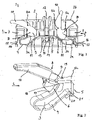
- figure 1 shows a connection terminal 1 with an insulating material housing 2, in which at least one pair of spring-loaded terminal connections 3a, 3b located opposite one another are installed.
- the spring clamp connections 3a, 3b each have a U-shaped clamp spring 4 and a common busbar piece 5.
- Each spring-loaded terminal connection 3a, 3b provides a clamping point through a clamping section 6 formed on the free, movable end of the clamping spring and in particular through the clamping edge on the free end of the clamping spring 4 and on the busbar section 5a opposite the clamping section 6.
- an associated conductor insertion opening 7 is introduced into the insulating housing for each spring-loaded terminal connection 3a, 3b.
- the conductor entry opening 7 has a diameter that is adapted to the largest possible cross section, including the insulating material jacket of an electrical conductor.
- each spring force terminal connection 3a, 3b has an actuating lever 8 with an actuating section 9 and an actuating arm 10 adjoining it and extending in a longitudinal direction.
- the left operating lever 8a is shown in the closed position and the right operating lever 8b in the open position of the clamping spring. It can be seen that the actuating levers 8a, 8b are pivoted through approximately 90° from the closed position to the open position. It is clear that the actuating lever 8a with its actuating section 9 and in particular the axis of rotation D about which the actuating levers 8a, 8b is pivotably mounted in the insulating material housing 2 of the connection terminal, in the space of the associated conductor insertion opening 7 or in the direction of conductor insertion L to the terminal point in the further extension of the Conductor insertion opening 7 is arranged. However, the axis of rotation D is still positioned in front of the clamping point as seen in the conductor insertion direction L and is by no means behind the clamping section 6 of the clamping spring 4 as seen in the conductor insertion direction L.
- an actuating tab 11 is free next to the clamping section 6 and protrudes obliquely from the clamping section 6 .
- an eccentric-like, projecting contour of the actuating section 9 of the associated actuating lever 8a, 8b acts on this actuating tab 11 at least partially during the movement sequence. In this way, the clamping section 6 of the clamping spring 4 is moved away from the adjacent busbar piece section 5a forming the clamping point, in order to open the clamping spring 4.
- actuating levers 8a, 8b are accommodated in recesses in the insulating material housing 2 for receiving a part of the actuating arm 10.
- the actuating arm 10 protrudes in the closed position (left actuating arm 8a in figure 1 ) opposite to the conductor insertion direction L on the respective front side of the associated conductor insertion opening 7 out of the insulating housing 2.
- An optional embodiment is also conceivable in which the actuating arm 10 is rotated through 180° and points in the conductor insertion direction L in the closed position. This is particularly conceivable for a terminal in which there is only one spring-cage terminal over the illustrated length of the terminal in conductor insertion direction L and several spring-cage terminals in the direction of the figure 1 seen are arranged distributed over the width.
- Terminal 1 shown is conceivable that not only such a pair of spring-loaded terminal connections 3a, 3b with associated actuating levers 8a, 8b is provided, but seen in the viewing direction over the width of the terminal several such arrangements are arranged side by side.
- a jumper insertion opening 12 is provided on the top of the insulating material housing, which is open to the top side of the insulating material housing 2 .
- the jumper insertion hole 12 opens into a jumper terminal connection formed by a material tab 13 of the conductor rail 5 and a downwardly bent end 14 of a clamping spring 4 .
- Such jumpers have at least two comb teeth which extend in parallel and which are electrically conductively connected to one another via a web which runs transversely thereto. At least this transverse web can be surrounded by an insulating material jacket in a manner known per se.
- the insulating material housing 2 is constructed in two parts and has a lower part 2a onto which an upper part 2b is snapped.
- latching lugs 16 of the lower part 2a dip into associated latching openings 17 of the upper part 2b.
- FIG 2 shows a perspective view of a spring clamp connection 3, which is formed from a U-shaped bent clamping spring 4 and a busbar section 5a.
- the busbar piece section 5a forming the clamping point has a clamping projection 18 at its free end, which creates a defined contact surface for an electrical conductor that is reduced in terms of its area.
- the clamping force of the clamping spring 4 is then concentrated via the electrical conductor onto this clamping surface defined by the clamping projection 18, so that the surface pressure is increased in comparison to a planar bearing surface.
- the free end of the busbar piece section 5a forming the clamping point is angled obliquely upwards in order to provide a guide for an electrical conductor to the clamping edge 18 .
- the busbar piece section 5a that forms the clamping point has a cutout 19 in the form of a depression, laterally adjacent to the clamping edge 18, into which the operating section 9 of the operating lever 8 dips.
- this cutout 19 the actuating tab 11 is released from the clamping section 6 of the clamping spring 4 and extends in the direction of the conductor insertion direction L.
- the side wall of the operating section 9 of the operating lever 8 forms a lateral boundary wall for an electrical conductor inserted to the terminal point, which is used to guide the electrical conductor to the terminal point.
- the busbar 5 is folded over laterally in such a way that at a distance and parallel to the busbar piece section 5a forming the clamping point, a bearing surface 20 for supporting a contact leg 21 of the clamping spring 4 is created.
- FIG 3 omits a perspective view of the spring clamp connection 3 with the actuating lever 8 figure 2 see from the other side.
- the actuating section 9 can only be used on the in figure 3 recognizable side a pivot pin 22 protrudes.
- the pivot pin 22 is circular and thus defines the axis of rotation D, about which the actuating lever 8 is accommodated in the insulating material housing 2 such that it can rotate.
- the pivot pin 22 is provided in order to dip into a corresponding opening or recess, not shown, in the insulating material housing of the connection terminal 1 .
- the actuating lever 8 is thus rotatably mounted on one side in the insulating material housing 2 by the pivot pin 22 serving as a bearing.
- the operating lever 8 is guided laterally only in sections by insulating material walls 2 and/or the busbar section 5a of the insulating material housing 2 without a specific pivot bearing.
- a suitable contour of the actuating section in coordination with the position of the axis of rotation D can, as shown, allow the open actuating lever 8 to be held in an over-center position.
- clamping spring 4 is formed in the form of a U-shaped clamping spring with a contact section 21, an adjoining spring arc 23 and in the adjoining clamping section 6 extending approximately in the direction of the contact leg 21.
- FIG 4 shows a variant of the connection terminal 1 in a reduced side sectional view. It is clear that the left-hand actuating lever 8a for the left-hand spring clamp connection protrudes upwards from the top of the insulating-material housing.
- the right-hand actuating lever 8b for the right-hand spring-loaded terminal connection 3b is arranged in a mirror-inverted manner in such a way that it protrudes from the underside of the insulating-material housing 2.
- connection terminals in which, viewed over the length of the connection terminal, there is only one spring clamp connection and not as in the exemplary embodiments figure 1 and 4 two spring clamp terminals 3a, 3b located one behind the other are provided.
- these embodiments are advantageously several such spring clamp terminals 3a across the width, ie in the direction of figure 4 seen arranged one after the other.
- the actuating levers 8 protrude alternately at the top and bottom, viewed across the width.
- the actuating arms 10 protrude alternately on the one hand in the conductor insertion direction and on the adjacent spring-loaded terminal connection 3 opposite to the conductor insertion direction L from the rear or front.
- FIG. 5 shows figure 5 an embodiment of a multi-row terminal 1 in the form of a box terminal.
- This terminal 1 has a plurality of spring clamp terminals 3 which are located next to one another and are electrically conductively connected to one another, the left-hand one of which is visible.
- a clamping spring 4 is attached to a busbar piece 5 .
- the clamping spring 4 is in turn bent into a U-shape, so that a clamping section 6 with a clamping cap at the free end protrudes against the busbar piece section 5a to form a clamping point.
- the clamping edge lies on the busbar piece section 5a.
- the clamping spring 4 has actuating tabs 11 on both sides of the clamping section 6.
- connection terminal 1 The conductor rail sections 5 of the spring-loaded terminal connections 3 arranged next to one another in the direction of view diagonally to the right can be connected to one another in an electrically conductive manner.
- connection terminal 1 an embodiment of the connection terminal 1 is also conceivable in which two spring-loaded terminal connections 3 lying next to one another are electrically connected to one another and two or three pairs of such spring-loaded terminal connections 3 connected to one another in an electrically conductive manner are provided.
- two conductors for a single-phase power supply connection can be connected to each other with the L (phase), N (neutral conductor) and PE (earth) connections, so that a mains connection terminal is formed.
- the actuating levers 8 are each arranged next to the clamping points, i.e. next to the busbar piece section 5a and the clamping section 6 directly behind the end of the conductor entry opening 7 formed in the insulating material housing 2 .
- the actuating sections 9 of the actuating levers 8 form a continuation of the wall of the respective conductor insertion opening 7 in order to guide an electrical conductor to the terminal point.
- Each actuation section 9 interacts with an associated actuation tab 11 of the clamping spring 4 .
- the axis of rotation of the actuating lever 8 is, as in the previously described embodiment, below the busbar piece section 5 in the area of the clamping point. The axis of rotation extends transversely to the conductor insertion direction, which is predetermined by the direction in which the conductor insertion opening 7 extends.
- the actuating arms 10 extend in the opposite direction to the conductor insertion direction L and are arranged on the upper side of the insulating housing 2 .
- the free ends of the actuating arms 10 are in the area of the front.
- the free ends of the actuating arms 10 are spaced apart from the boundary walls of the conductor entry opening 7 or the insulating housing 2 in such a way that they can be gripped and pivoted by hand.
- figure 6 shows a perspective view of such an operating lever 8 seen from the front. It is clear, however, that there is an opening 24 in the middle, central area, into which a guide wall of the insulating material housing dips in order to guide the actuating lever 8 in the insulating material housing 2 in a tilt-proof manner.
- the opening 24 is surrounded in the upper area by a peripheral collar. This serves to reinforce and stiffen the operating lever 8.
- the actuating lever has a pivot pin 22 serving as a bearing at its two lateral outer ends.
- the pivot pins 22 are received in corresponding openings in the insulating material housing 2 .
- the opposing actuating sections 9 thus serve as a continuation of the conductor insertion opening 7.
- the actuating levers 8 can have latching grooves 26 or projecting latching pins on the opposite side edges of the actuating arms 10 in order to latch the actuating lever to the insulating material housing 2 in the closed state and to prevent the actuating lever 8 from being opened unintentionally with reduced force.
- FIG 8 omits a perspective view of the operating lever figure 6 and 7 seen from the bottom. It becomes clear that the opening 24 is closed again in the lower area. It can also be seen that the walls that form the actuating sections 9 merge into the actuating arm 10 via webs 27 on the underside of the actuating arm, thus forming the actuating arm 10 and to prevent deflection relative to the actuating sections 9 .
- the actuating sections 9 have a contour matched to the axis of rotation D in such a way that the opened actuating lever 8 remains self-retaining in an over-center position.
- FIG 9 shows a further embodiment of a connection terminal 1 with a plurality of spring-loaded terminal connections 3 arranged one behind the other in the viewing direction and associated actuating levers 8 .
- the actuating lever 8 is shown upwards in the closed position, in which the clamping spring 4 of the spring-loaded terminal connection 3 is closed.
- figure 10 shows the same actuating lever 8 in the open position, in which the spring-loaded terminal connection 3 is open.
- the actuating lever 8 is arranged with its actuating section 9 directly behind the conductor insertion opening 7 in turn laterally next to the busbar piece 5 or the busbar piece section 5a forming the clamping point.
- the axis of rotation D is in the conductor insertion opening 7 or directly behind it and viewed in the direction of conductor insertion L shortly before the terminal point and below the terminal point-forming busbar piece section 5a.
- the actuating arms 10 of the actuating levers 8 are directed away from the conductor insertion openings 7 in the direction of the rear side of the connection terminal 1 in the conductor insertion direction L. This enables a very compact construction of the connection terminal 1 with simple and reliable actuation of the spring-loaded terminal connection 3 .
- test opening 28 which is open to the clamping spring 4 is provided on the rear side of the insulating material housing 2 in the lower region. In this way, the voltage potential present at the spring-loaded terminal connection can be measured using a test pin inserted into the test opening 28 .
- figure 11 omits a side view of the actuating levers 8 of the connection terminal 1 Figure 9 and 10 recognize. It is clear that the actuating arm 10 initially protrudes obliquely backwards from the actuating section 9 and then in the direction L of conductor insertion. The cross piece 10c can also be seen at the lower free end of the actuating arm 10.
- the operating section 9 has a nose 30 which is matched to the position of the axis of rotation in such a way that the open operating lever 8 remains self-retaining in an over-center position.
- FIG 12 omits a view of the actuator arm figure 11 see from below.
- the construction of the actuating arm 10 with two arm sections 10a, 10b and the crosspiece 10c connecting the arm sections 10a, 10b at the free end becomes clear.
- pivot pins 22 protrude laterally on the outer sides of the actuating sections 9 and are mounted in corresponding depressions in the insulating material housing 2 of the connection terminal 1 .
Landscapes
- Connections Arranged To Contact A Plurality Of Conductors (AREA)
- Coupling Device And Connection With Printed Circuit (AREA)
- Details Of Connecting Devices For Male And Female Coupling (AREA)
- Clamps And Clips (AREA)
- Ceramic Capacitors (AREA)
- Wire Bonding (AREA)
- Fixing For Electrophotography (AREA)
Claims (10)
- Borne de raccordement (1) comprenant:- au moins une pièce de barre-bus (5) et- au moins un ressort de serrage (4),la borne de raccordement (1) comportant au moins une borne à serrage par ressort (3, 3a, 3b) formée d'un ressort de serrage (4) et d'une portion (5a) d'une pièce de barre-bus (5), pour serrer un conducteur électrique entre exactement une portion de serrage du ressort de serrage (4) et la portion de pièce de barre-bus (5a) en exactement un point de serrage,- et comprenant un boîtier en matériau isolant (2), lequel comporte au moins une ouverture d'introduction de conducteur (7) qui mène à une borne à serrage par ressort (3, 3a, 3b) associée et qui s'étend dans la direction d'introduction de conducteur (L), dans lequel le conducteur électrique sort de l'ouverture d'introduction de conducteur (7) délimité latéralement circonférentiellement vers le point de serrage à partir de l'ouverture d'introduction de conducteur (7),- et comprenant au moins un levier d'actionnement (8, 8a, 8b) monté pivotant, lequel est configuré pour coopérer par le biais d'une portion d'actionnement (9) avec au moins un ressort de serrage (4) pour ouvrir au moins une borne à serrage par ressort (3, 3a, 3b) associée lors du pivotement du levier d'actionnement (8, 8a, 8b) et comportant un bras d'actionnement (10) qui se raccorde à la portion d'actionnement (9), - l'axe de rotation (D) du levier d'actionnement (8, 8a, 8b) étant disposé transversalement par rapport à la direction d'introduction de conducteur (L) dans une ouverture d'introduction de conducteur (7) associée ou dans la prolongation de l'ouverture d'introduction de conducteur (7) qui se poursuit jusqu'au point de serrage dans la direction d'introduction de conducteur (L),caractérisée en ce que
l'au moins un levier d'actionnement (8, 8a, 8b) est disposé adjacent à une portion de pièce de barre-bus (5a) associée formant le point de serrage de telle sorte que l'axe de rotation (D) du levier d'actionnement (8, 8a, 8b) est disposé dans l'espace entre le plan couvert par la portion de pièce de barrebus (5a) et un plan parallèle à celui-ci, dans lequel se trouve le bord de serrage du ressort de serrage (4) entièrement ouvert lors du retournement du levier d'actionnement (8, 8a, 8b) . - Borne de raccordement (1) selon la revendication 1, caractérisée en ce que le levier d'actionnement (8, 8a, 8b) comprend au moins une paroi de délimitation latérale destinée au guidage d'un conducteur électrique introduit dans une ouverture d'introduction de conducteur (7) dans une direction d'introduction de conducteur (L) vers un point de serrage associé.
- Borne de raccordement (1) selon l'une des revendications précédentes, caractérisée en ce qu'au moins un levier d'actionnement (8, 8a, 8b) s'enfonce dans une découpe (19) de la pièce de barre-bus (5) pratiquée adjacente à une portion de serrage de la portion de pièce de barre-bus (5a) associée et, avec une portion d'actionnement (9), charge une languette d'actionnement (11) disposée à côté de la portion de serrage (6) d'un ressort de serrage (4) associé, vue dans le sens de la largeur du ressort de serrage (4), pour ouvrir le ressort de serrage (4).
- Borne de raccordement (1) selon la revendication 3, caractérisée en ce que la languette d'actionnement (11) est libérée par le ressort de serrage (4) et fait saillie en biais par rapport à la portion de serrage (6) du ressort de serrage (4).
- Borne de raccordement (1) selon l'une des revendications précédentes, caractérisée en ce que l'au moins un ressort de serrage (4) est un ressort de serrage (4) courbé en forme de U dont la portion de ressort libre (6) est orientée en biais en direction d'une pièce de barre-bus (5) associée afin de permettre une insertion directe d'un conducteur électrique sans ouvrir préalablement le ressort de serrage (4) avec le levier d'actionnement (8, 8a, 8b) associé.
- Borne de raccordement (1) selon l'une des revendications précédentes, caractérisée en ce que l'au moins un levier d'actionnement (8, 8a, 8b) est monté en rotation dans le boîtier en matériau isolant (2) de la borne de raccordement (1) uniquement sur un côté doté d'un tourillon (22) en saillie, lequel est logé de manière rotative dans une ouverture correspondante du boîtier en matériau isolant (2) de la borne de raccordement (1) autour d'un axe de rotation (D) défini par le tourillon (22) .
- Borne de raccordement (1) selon l'une des revendications précédentes, caractérisée en ce que l'au moins un levier d'actionnement (8, 8a, 8b) comprend un bras d'actionnement (10) qui, à l'état fermé de la borne à serrage par ressort (3, 3a, 3b) associée, s'étend dans la direction d'introduction de conducteur (L).
- Borne de raccordement (1) selon l'une des revendications précédentes, caractérisée en ce que l'au moins un levier d'actionnement (8, 8a, 8b) comprend un bras d'actionnement (10) qui s'étend sur le dessous ou sur le dessus de la borne de raccordement (1) dans la direction d'introduction de conducteur (L) ou à l'opposé de celle-ci.
- Borne de raccordement (1) selon l'une des revendications précédentes, caractérisée en ce que la borne de raccordement (1) comprend au moins une paire de bornes à serrage par ressort (3, 3a, 3b) mutuellement opposées avec des ouvertures d'introduction de conducteur (7) qui convergeant l'une vers l'autre sur le côté avant et le côté arrière mutuellement opposés de la borne de raccordement (1), un levier d'actionnement pourvu d'un bras d'actionnement étant associé à chaque borne à serrage par ressort (3, 3a, 3b) d'une paire, dont les bras d'actionnement sont orientés dans des directions opposées l'une à l'autre.
- Borne de raccordement (1) selon la revendication 9, caractérisée en ce que les bras d'actionnement (10) d'une paire de leviers d'actionnement (8, 8a, 8b) sont disposés sur le même côté ou sur des côtés mutuellement opposés de la borne de raccordement (1).
Priority Applications (3)
| Application Number | Priority Date | Filing Date | Title |
|---|---|---|---|
| EP16187324.5A EP3125372B2 (fr) | 2011-12-14 | 2012-12-12 | Borne de connexion |
| DK16187324.5T DK3125372T3 (en) | 2011-12-14 | 2012-12-12 | Terminals |
| PL16187324T PL3125372T3 (pl) | 2011-12-14 | 2012-12-12 | Zacisk przyłączeniowy |
Applications Claiming Priority (1)
| Application Number | Priority Date | Filing Date | Title |
|---|---|---|---|
| DE102011056410A DE102011056410B4 (de) | 2011-12-14 | 2011-12-14 | Anschlussklemme |
Related Child Applications (2)
| Application Number | Title | Priority Date | Filing Date |
|---|---|---|---|
| EP16187324.5A Division EP3125372B2 (fr) | 2011-12-14 | 2012-12-12 | Borne de connexion |
| EP16187324.5A Division-Into EP3125372B2 (fr) | 2011-12-14 | 2012-12-12 | Borne de connexion |
Publications (4)
| Publication Number | Publication Date |
|---|---|
| EP2605335A2 EP2605335A2 (fr) | 2013-06-19 |
| EP2605335A3 EP2605335A3 (fr) | 2014-04-16 |
| EP2605335B1 EP2605335B1 (fr) | 2016-09-21 |
| EP2605335B2 true EP2605335B2 (fr) | 2022-10-19 |
Family
ID=47429791
Family Applications (3)
| Application Number | Title | Priority Date | Filing Date |
|---|---|---|---|
| EP12806010.0A Active EP2792024B1 (fr) | 2011-12-14 | 2012-12-11 | Borne de raccordement munie d'un levier d'actionnement monté de manière à pouvoir pivoter autour d'un axe de rotation |
| EP12196722.8A Active EP2605335B2 (fr) | 2011-12-14 | 2012-12-12 | Borne de connexion |
| EP16187324.5A Active EP3125372B2 (fr) | 2011-12-14 | 2012-12-12 | Borne de connexion |
Family Applications Before (1)
| Application Number | Title | Priority Date | Filing Date |
|---|---|---|---|
| EP12806010.0A Active EP2792024B1 (fr) | 2011-12-14 | 2012-12-11 | Borne de raccordement munie d'un levier d'actionnement monté de manière à pouvoir pivoter autour d'un axe de rotation |
Family Applications After (1)
| Application Number | Title | Priority Date | Filing Date |
|---|---|---|---|
| EP16187324.5A Active EP3125372B2 (fr) | 2011-12-14 | 2012-12-12 | Borne de connexion |
Country Status (13)
| Country | Link |
|---|---|
| US (2) | US9124034B2 (fr) |
| EP (3) | EP2792024B1 (fr) |
| JP (3) | JP5833774B2 (fr) |
| KR (1) | KR101558119B1 (fr) |
| CN (3) | CN103999290B (fr) |
| BR (1) | BR112014014271B1 (fr) |
| DE (1) | DE102011056410B4 (fr) |
| DK (3) | DK2792024T3 (fr) |
| ES (3) | ES2569727T3 (fr) |
| PL (3) | PL2792024T3 (fr) |
| PT (2) | PT2605335T (fr) |
| RU (1) | RU2572567C1 (fr) |
| WO (1) | WO2013087619A1 (fr) |
Families Citing this family (98)
| Publication number | Priority date | Publication date | Assignee | Title |
|---|---|---|---|---|
| DE102012110895B4 (de) * | 2012-11-13 | 2015-03-26 | Wago Verwaltungsgesellschaft Mbh | Anschlussklemme |
| DE102013101406B4 (de) | 2013-02-13 | 2018-07-12 | Wago Verwaltungsgesellschaft Mbh | Leiteranschlussklemme |
| DE102013101409B4 (de) * | 2013-02-13 | 2022-01-20 | Wago Verwaltungsgesellschaft Mbh | Leiteranschlussklemme |
| DE202013100635U1 (de) | 2013-02-13 | 2013-03-04 | Wago Verwaltungsgesellschaft Mbh | Federklemmkontakt und Verbindungsklemme für elektrische Leiter |
| DE102013101410A1 (de) * | 2013-02-13 | 2014-08-14 | Wago Verwaltungsgesellschaft Mbh | Federkraftklemmanschluss und Leiteranschlussklemme |
| DE102013101408B4 (de) * | 2013-02-13 | 2021-01-14 | Wago Verwaltungsgesellschaft Mbh | Federkraftklemmelement und Verbindungsklemme |
| DE102013101411B4 (de) | 2013-02-13 | 2018-03-22 | Wago Verwaltungsgesellschaft Mbh | Federkraftklemmanschluss und Leiteranschlussklemme |
| DE102013004666A1 (de) * | 2013-03-19 | 2014-09-25 | Phoenix Contact Gmbh & Co. Kg | Klemmenblockanordnung |
| DE202013101582U1 (de) | 2013-04-15 | 2014-07-16 | Weidmüller Interface GmbH & Co. KG | Federkraftklemmelement mit Schwenkhebel |
| USD745459S1 (en) * | 2013-06-17 | 2015-12-15 | Wago Verwaltungsgesellschaft Mbh | Electrical plug-in connector |
| DE102013110477B4 (de) * | 2013-09-23 | 2021-11-04 | Phoenix Contact Gmbh & Co. Kg | Durchführungsklemme und elektrische Baueinrichtung |
| DE102013110475A1 (de) * | 2013-09-23 | 2015-03-26 | Phoenix Contact Gmbh & Co. Kg | Elektrische Anschlussklemme |
| DE102013110476A1 (de) * | 2013-09-23 | 2015-03-26 | Phoenix Contact Gmbh & Co. Kg | Kabelschuheinrichtung mit Strombalken sowie Anschlussklemme |
| DE102013110789B3 (de) * | 2013-09-30 | 2014-12-04 | Klaus Bruchmann Gmbh | Adapter zum Kontaktieren von Sammelschienen |
| DE102013111574B4 (de) * | 2013-10-21 | 2017-01-12 | Wago Verwaltungsgesellschaft Mbh | Federkraftklemmanschluss und Steckverbinder |
| DE102014102517B4 (de) * | 2014-02-26 | 2021-06-10 | Wago Verwaltungsgesellschaft Mbh | Verbindungsklemme und Federkraftklemmkontakt hierzu |
| JP6406049B2 (ja) | 2014-03-26 | 2018-10-17 | 株式会社デンソー | 正極材料,非水電解質二次電池用正極及び非水電解質二次電池 |
| US9397416B2 (en) * | 2014-08-22 | 2016-07-19 | Tyco Electronics Corporation | Electrical connector having poke-in wire contacts |
| DE102014114026B4 (de) | 2014-09-26 | 2023-03-30 | Wago Verwaltungsgesellschaft Mbh | Leiteranschlussklemme und Verfahren zu deren Montage |
| TWM502983U (zh) * | 2014-12-04 | 2015-06-11 | Switchlab Inc | 軌道型電聯接端子之導電接線結構 |
| DE102014119030A1 (de) * | 2014-12-18 | 2016-06-23 | Phoenix Contact Gmbh & Co. Kg | Anschlussklemme |
| DE102014119420B3 (de) * | 2014-12-22 | 2016-05-12 | Wago Verwaltungsgesellschaft Mbh | Anschlussklemme |
| DE102014119421B4 (de) * | 2014-12-22 | 2017-02-02 | Wago Verwaltungsgesellschaft Mbh | Verbindungsklemme und Verfahren zur Montage einer Verbindungsklemme |
| DE102015100257A1 (de) * | 2014-12-22 | 2016-06-23 | Wago Verwaltungsgesellschaft Mbh | Leiteranschlussklemme zum Anklemmen wenigstens eines elektrischen Leiters |
| DE102015100823B4 (de) * | 2015-01-21 | 2021-12-09 | Phoenix Contact Gmbh & Co. Kg | Elektrische Anschlussklemme |
| CN104638455A (zh) * | 2015-02-06 | 2015-05-20 | 胡和萍 | 一种燃气热水炉控制电路连接器 |
| WO2016164219A1 (fr) | 2015-04-08 | 2016-10-13 | Phoenix Contact Development and Manufacturing, Inc. | Plaque à bornes |
| CN104767045B (zh) * | 2015-04-11 | 2017-03-29 | 江门市创艺电器有限公司 | 一种接线端子连接器 |
| CN204558667U (zh) * | 2015-04-11 | 2015-08-12 | 江门市创艺电器有限公司 | 一种接线端子连接器 |
| KR102476138B1 (ko) * | 2015-08-19 | 2022-12-14 | 삼성전자주식회사 | 커넥터, 광원모듈 및 이를 이용한 광원모듈 어레이 |
| DE102015115612A1 (de) * | 2015-09-16 | 2017-03-16 | Phoenix Contact Gmbh & Co. Kg | Anschlussklemme zum Anschließen eines elektrischen Leiters |
| DE202015105022U1 (de) * | 2015-09-22 | 2016-12-23 | Weidmüller Interface GmbH & Co. KG | Anschlussvorrichtung für Leiter |
| JP2017073284A (ja) * | 2015-10-07 | 2017-04-13 | Smk株式会社 | ケーブル接続用コネクタ |
| DE102015118032B4 (de) * | 2015-10-22 | 2017-11-16 | Wago Verwaltungsgesellschaft Mbh | Leiteranschlussklemme |
| DE102015119247A1 (de) | 2015-11-09 | 2017-05-11 | Wago Verwaltungsgesellschaft Mbh | Verbindungsklemme |
| DE102015122143B4 (de) * | 2015-12-17 | 2019-02-14 | Wago Verwaltungsgesellschaft Mbh | Leiteranschlussklemme |
| JP6571517B2 (ja) * | 2015-12-24 | 2019-09-04 | ヒロセ電機株式会社 | 端子着脱装置 |
| CN105490038B (zh) * | 2016-01-08 | 2017-12-05 | 林家鹳 | 一种接线端子 |
| CN107104303B (zh) * | 2016-02-19 | 2020-05-12 | 进联电子科技(上海)有限公司 | 电联接端子结构 |
| US9466897B1 (en) * | 2016-03-01 | 2016-10-11 | Dinkle Enterprises Co., Ltd. | Double-wire terminal block structure |
| JP2017183023A (ja) * | 2016-03-29 | 2017-10-05 | パナソニックIpマネジメント株式会社 | 端子装置及びそれを備えた配線器具 |
| LU93033B1 (de) * | 2016-04-20 | 2017-11-30 | Phoenix Contact Gmbh & Co Kg Intellectual Property Licenses & Standards | Elektrische Anschlussklemme und Verfahren |
| US10658766B2 (en) * | 2016-05-30 | 2020-05-19 | Weidmüller Interface GmbH & Co. KG | Spring terminal for a conductor |
| AT15515U1 (de) * | 2016-06-13 | 2017-11-15 | Benedict Gmbh | Federkraftklemme |
| DE102016111627A1 (de) | 2016-06-24 | 2017-12-28 | Wago Verwaltungsgesellschaft Mbh | Leiteranschlussklemme |
| WO2018004482A1 (fr) * | 2016-06-30 | 2018-01-04 | Tp Elektri̇k Malzemeleri̇ Sanayi̇ Ve Ti̇caret Anoni̇m Şi̇rketi̇ | Bloc de bornes pour fiche ou douille comportant des contacts à ressort pour fil actionnés par des leviers |
| LU93148B1 (de) * | 2016-07-13 | 2018-01-23 | Phoenix Contact Gmbh & Co Kg Intellectual Property Licenses & Standards | Anschlussklemme |
| DE102016115490B4 (de) * | 2016-08-22 | 2018-06-07 | Harting Electric Gmbh & Co. Kg | Anschlusselement |
| DE102016115601A1 (de) | 2016-08-23 | 2018-03-01 | Wago Verwaltungsgesellschaft Mbh | Federkraftklemmanschluss |
| LU93183B1 (de) | 2016-08-25 | 2018-03-28 | Phoenix Contact Gmbh & Co Kg Intellectual Property Licenses & Standards | Anschlussklemme |
| DE102016116510A1 (de) * | 2016-09-02 | 2018-03-08 | Wago Verwaltungsgesellschaft Mbh | Leiteranschlussklemme |
| JP6817440B2 (ja) * | 2016-12-06 | 2021-01-20 | レイセオン カンパニー | コネクタ取外しツール |
| CA3049409A1 (fr) | 2017-01-06 | 2018-07-12 | Hubbell Incorporated | Dispositifs de cablage electrique a bornes de connexion sans vis |
| JP6801516B2 (ja) * | 2017-02-28 | 2020-12-16 | オムロン株式会社 | 端子台 |
| DE102017109694B4 (de) * | 2017-05-05 | 2022-10-06 | Wago Verwaltungsgesellschaft Mbh | Anschlussklemme |
| CN207664252U (zh) * | 2017-05-05 | 2018-07-27 | 陈斌斌 | 一种接线端子 |
| DE202017107800U1 (de) * | 2017-05-12 | 2018-08-17 | Electro Terminal Gmbh & Co Kg | Klemme |
| CN107181074A (zh) * | 2017-06-13 | 2017-09-19 | 广州高权电器灯饰有限公司 | 一种接线端子 |
| DE102017115137A1 (de) * | 2017-07-06 | 2019-01-10 | Dr. Ing. H.C. F. Porsche Aktiengesellschaft | Kontaktschieneneinrichtung für ein wenigstens teilweise elektrisch angetriebenes Fahrzeug |
| TWI691132B (zh) * | 2017-07-06 | 2020-04-11 | 進聯工業股份有限公司 | 導線聯接端子之導電組件結構 |
| CN108075252B (zh) * | 2017-07-12 | 2023-08-01 | 安波福中央电气(上海)有限公司 | 电连接器 |
| BE1025389B1 (de) * | 2017-07-14 | 2019-02-12 | Phoenix Contact Gmbh & Co. Kg | ANSCHLUSSEINRICHTUNG ZUM ANSCHLIEßEN EINER ELEKTRISCHEN LEITUNG |
| WO2019036362A1 (fr) * | 2017-08-16 | 2019-02-21 | Molex, Llc | Ensemble connecteur électrique |
| DE202017105467U1 (de) | 2017-09-08 | 2018-12-12 | Wago Verwaltungsgesellschaft Mbh | Leiteranschlussklemme |
| DE202017107208U1 (de) * | 2017-11-28 | 2019-03-04 | Weidmüller Interface GmbH & Co. KG | Anschlussvorrichtung zum Anschluss eines Leiterendes |
| DE202018101729U1 (de) * | 2018-03-28 | 2019-07-01 | Wago Verwaltungsgesellschaft Mbh | Leiteranschlussklemme, Klemmfeder einer Leiteranschlussklemme sowie Reihenklemme |
| DE202018101726U1 (de) * | 2018-03-28 | 2019-07-01 | Wago Verwaltungsgesellschaft Mbh | Leiteranschlussklemme, Klemmfeder einer Leiteranschlussklemme sowie Reihenklemme |
| DE202018101731U1 (de) * | 2018-03-28 | 2019-07-01 | Wago Verwaltungsgesellschaft Mbh | Leiteranschlussklemme, Klemmfeder einer Leiteranschlussklemme sowie Reihenklemme |
| USD914613S1 (en) * | 2018-04-19 | 2021-03-30 | Wago Verwaltungsgesellschaft Mbh | Electric terminal |
| CN110416749B (zh) * | 2018-04-27 | 2021-02-05 | 达昌电子科技(苏州)有限公司 | 端子台 |
| TR201809553A2 (tr) * | 2018-07-04 | 2018-07-23 | Eae Elektrik Asansoer Enduestrisi Insaat Sanayi Ve Ticaret Anonim Sirketi | Busbar i̇çi̇n bi̇r ek bağlanti modülü |
| DE102018117508B4 (de) * | 2018-07-19 | 2024-01-18 | Wago Verwaltungsgesellschaft Mbh | Leiteranschlussklemme |
| CN109038035B (zh) * | 2018-07-20 | 2020-01-07 | 上海航天科工电器研究院有限公司 | 一种采用滑块快速锁线的连接器 |
| JP7095489B2 (ja) * | 2018-08-27 | 2022-07-05 | オムロン株式会社 | コネクタ式スクリューレス端子台 |
| CN109149152B (zh) * | 2018-09-11 | 2020-09-01 | 余姚市信亿电子科技有限公司 | 一种导线连接器 |
| DE102018124623B4 (de) * | 2018-10-05 | 2022-07-07 | Wago Verwaltungsgesellschaft Mbh | Kontakteinsatz einer Leiteranschlussklemme sowie damit gebildete Leiteranschlussklemme |
| US10418727B1 (en) * | 2018-11-15 | 2019-09-17 | Dinkle Enterprise Co., Ltd. | Rotate-to-open clamping unit and connection device having the same |
| DE202018106896U1 (de) | 2018-12-04 | 2020-03-05 | WAGO Verwaltungsgesellschaft mit beschränkter Haftung | Federanschlussklemme |
| CN109510007B (zh) * | 2018-12-05 | 2023-09-29 | 天立电机(宁波)有限公司 | 插拔式接线端子 |
| DE102018131794B4 (de) | 2018-12-11 | 2023-06-01 | Wago Verwaltungsgesellschaft Mbh | Leiteranschlussklemme |
| US10511108B1 (en) * | 2019-01-07 | 2019-12-17 | Dinkle Enterprise Co., Ltd. | Dual-wire connector |
| DE102019104704A1 (de) * | 2019-02-25 | 2020-08-27 | Harting Electric Gmbh & Co. Kg | Anschlusseinrichtung für elektrische Leiter |
| CN110112585B (zh) * | 2019-05-20 | 2024-04-19 | 安费诺商用电子产品(成都)有限公司 | 一种快速锁线机构 |
| DE202019105009U1 (de) | 2019-09-11 | 2020-12-14 | Wago Verwaltungsgesellschaft Mbh | Leiteranschlussklemme |
| LU101419B1 (de) | 2019-09-27 | 2021-03-31 | Phoenix Contact Gmbh & Co | Verriegelbares Anschlussmodul |
| DE202020100089U1 (de) * | 2020-01-09 | 2021-04-12 | Wago Verwaltungsgesellschaft Mbh | Leiteranschlussklemme |
| DE102020104077A1 (de) * | 2020-02-17 | 2021-08-19 | WAGO Verwaltungsgesellschaft mit beschränkter Haftung | Federkraftklemmanschluss |
| DE102021108316A1 (de) * | 2020-04-03 | 2021-10-07 | Phoenix Contact Gmbh & Co. Kg | Anschlussklemme und elektronisches Gerät |
| US11095053B1 (en) * | 2020-06-10 | 2021-08-17 | Dinkle Enterprise Co., Ltd. | Tool-less terminal block |
| JPWO2022014526A1 (fr) * | 2020-07-17 | 2022-01-20 | ||
| DE202020105715U1 (de) * | 2020-10-06 | 2022-01-10 | Electro Terminal GmbH & Co. KG | Klemme mit Lösehebel |
| US11791573B2 (en) | 2021-04-15 | 2023-10-17 | Leviton Manufacturing Co., Inc. | Wire terminals and method of uses |
| US11670878B2 (en) * | 2021-05-18 | 2023-06-06 | Dinkle Enterprise Co., Ltd. | Terminal block structure |
| DE202021103878U1 (de) | 2021-07-21 | 2022-11-04 | Electro Terminal GmbH & Co. KG | Klemme mit Lösehebel |
| EP4123839A1 (fr) * | 2021-07-21 | 2023-01-25 | Electro Terminal GmbH & Co KG | Borne de connexion électrique pourvue de levier de libération |
| WO2023095687A1 (fr) * | 2021-11-29 | 2023-06-01 | Idec株式会社 | Dispositif de liaison et dispositif électronique |
| DE102022100132A1 (de) | 2022-01-04 | 2023-07-06 | Phoenix Contact Gmbh & Co. Kg | Elektrische Anschlussvorrichtung |
| WO2024005776A1 (fr) | 2022-06-27 | 2024-01-04 | Ideal Industries, Inc. | Connecteur à levier pour conducteurs électriques |
Citations (3)
| Publication number | Priority date | Publication date | Assignee | Title |
|---|---|---|---|---|
| DE8424056U1 (de) † | 1984-08-14 | 1984-11-15 | Gira Elektrotechnische Industrie Gustav Giersiepen, 5608 Radevormwald | Schraubenlose Anschlußklemme für elektrische Geräte, insbesondere für Installationsgeräte |
| DE29915515U1 (de) † | 1999-09-03 | 2001-02-01 | Weidmueller Interface | Federklemme zum Anschließen elektricher Leiter |
| DE202009010003U1 (de) † | 2008-08-20 | 2009-12-03 | LEGRAND FRANCE (société anonyme) | Automatischer elektrischer Verbindungsanschluss |
Family Cites Families (34)
| Publication number | Priority date | Publication date | Assignee | Title |
|---|---|---|---|---|
| DE1898970U (de) * | 1964-06-08 | 1964-08-20 | Wago Klemmenwerk G M B H | Federdruck-klemme. |
| DE1975279U (de) | 1967-07-15 | 1967-12-21 | Berker Geb | Im sockel eines installationsgeraetes angeordnete anschlussklemme fuer elektrische leiter. |
| DE1975278U (de) * | 1967-07-15 | 1967-12-21 | Berker Geb | Im sockel eines installationsgeraetes angeordnete anschlussklemme fuer elektrische leiter. |
| DE1984159U (de) | 1967-12-07 | 1968-04-25 | Friedrich Merk Telefonbau G M | Klemmvorrichtung fuer den anschluss elektrischer leitungen. |
| CH619324A5 (en) | 1977-08-10 | 1980-09-15 | Feller Ag | Screwless electrical connecting terminal |
| AT376524B (de) | 1978-06-05 | 1984-11-26 | Siemens Ag Oesterreich | Reihenklemme zur loesbaren elektrisch leitenden verbindung |
| DE8704494U1 (fr) * | 1987-03-26 | 1987-06-11 | Popp + Co Gmbh, 8582 Bad Berneck, De | |
| DE3743410A1 (de) * | 1987-12-21 | 1989-06-29 | Electro Terminal Gmbh | Schraubenlose verbindungsklemme |
| JP2594190Y2 (ja) * | 1992-08-07 | 1999-04-19 | 株式会社白山製作所 | 差し込み形接続端子 |
| DE4233446C1 (de) * | 1992-10-05 | 1993-10-21 | Wieland Elektrische Industrie | Schraubenlose Federklemme |
| JP3395540B2 (ja) * | 1996-05-28 | 2003-04-14 | 松下電工株式会社 | 電線接続端子 |
| IT1283503B1 (it) | 1996-07-25 | 1998-04-21 | Claber Spa | Morsetto a leva per connettori elettrici |
| US6146187A (en) * | 1998-11-25 | 2000-11-14 | Supplie & Co. Import/Export, Inc. | Screwless terminal block |
| JP2000260501A (ja) * | 1999-03-11 | 2000-09-22 | Nitto Electric Works Ltd | 端子装置 |
| JP2003249283A (ja) * | 2002-02-21 | 2003-09-05 | Kawamura Electric Inc | 速結端子 |
| DE10261536B4 (de) | 2002-12-23 | 2009-12-10 | Wago Verwaltungsgesellschaft Mbh | Anschluss- und Verbindungsklemme für elektrische Leiter |
| JP4052171B2 (ja) | 2003-04-18 | 2008-02-27 | 松下電工株式会社 | 速結端子装置 |
| JP4046102B2 (ja) * | 2004-05-26 | 2008-02-13 | 松下電工株式会社 | 端子装置 |
| ES2247929B1 (es) | 2004-06-10 | 2007-04-01 | Simon, S.A. | Mecanismo de embornado y desembornado rapido par dispositivos electricos. |
| JP4289230B2 (ja) * | 2004-06-25 | 2009-07-01 | パナソニック電工株式会社 | 速結端子装置 |
| FR2873859B1 (fr) * | 2004-07-30 | 2006-12-08 | Legrand Sa | Appareil electrique comportant une borne a connexion automatique |
| FR2875944B1 (fr) * | 2004-09-27 | 2006-12-15 | Legrand Sa | Appareil comportant un bloc de raccordement |
| DE102006001812A1 (de) | 2005-12-05 | 2007-06-06 | Km Europa Metal Ag | Kokille zum Stranggießen von Metall |
| DE202006020822U1 (de) | 2006-04-19 | 2010-08-05 | Phoenix Contact Gmbh & Co. Kg | Federkraftklemme |
| DE102006047254B3 (de) * | 2006-10-06 | 2008-05-21 | Abb Ag | Installationsschaltgerät |
| DE102007051900B4 (de) * | 2007-10-29 | 2009-09-10 | Wago Verwaltungsgesellschaft Mbh | Federkraftanschluss |
| CN102132460B (zh) * | 2008-08-27 | 2013-09-18 | 菲尼克斯电气公司 | 电接线端子 |
| DE102008062137B4 (de) * | 2008-12-16 | 2011-06-09 | Wago Verwaltungsgesellschaft Mbh | Leiteranschlussklemme |
| DE202009002040U1 (de) * | 2009-01-23 | 2009-08-06 | Wischemann, Heinrich | Halterung für ein Solarmodul |
| DE202009002240U1 (de) | 2009-02-17 | 2010-07-22 | Phoenix Contact Gmbh & Co. Kg | Elektrische Anschlussklemme |
| JP5491837B2 (ja) † | 2009-12-04 | 2014-05-14 | パナソニック株式会社 | 速結端子装置 |
| ITTO20100677A1 (it) * | 2010-08-04 | 2012-02-05 | Tyco Electronics Amp Italia Srl | Connettore elettrico atto a realizzare un contatto diretto fra un conduttore elettrico ed una rispettiva controparte |
| US8113858B1 (en) * | 2011-08-20 | 2012-02-14 | Cheng Uei Precision Industry Co., Ltd. | Cable connector having switching function |
| US20140113502A1 (en) * | 2012-09-28 | 2014-04-24 | Phoenix Contact Development & Manufacturing, Inc. | Connector Block with Spring-Loaded Electrical Terminal Assemblies |
-
2011
- 2011-12-14 DE DE102011056410A patent/DE102011056410B4/de not_active Withdrawn - After Issue
-
2012
- 2012-12-11 ES ES12806010.0T patent/ES2569727T3/es active Active
- 2012-12-11 RU RU2014128525/07A patent/RU2572567C1/ru active
- 2012-12-11 WO PCT/EP2012/075069 patent/WO2013087619A1/fr active Application Filing
- 2012-12-11 PL PL12806010T patent/PL2792024T3/pl unknown
- 2012-12-11 KR KR1020147016057A patent/KR101558119B1/ko active IP Right Grant
- 2012-12-11 EP EP12806010.0A patent/EP2792024B1/fr active Active
- 2012-12-11 JP JP2014546459A patent/JP5833774B2/ja active Active
- 2012-12-11 CN CN201280062263.4A patent/CN103999290B/zh active Active
- 2012-12-11 BR BR112014014271-8A patent/BR112014014271B1/pt active IP Right Grant
- 2012-12-11 DK DK12806010.0T patent/DK2792024T3/da active
- 2012-12-11 US US14/363,578 patent/US9124034B2/en active Active
- 2012-12-11 JP JP2012270055A patent/JP6184089B2/ja active Active
- 2012-12-12 ES ES16187324.5T patent/ES2662899T3/es active Active
- 2012-12-12 ES ES12196722T patent/ES2606362T5/es active Active
- 2012-12-12 EP EP12196722.8A patent/EP2605335B2/fr active Active
- 2012-12-12 PL PL16187324T patent/PL3125372T3/pl unknown
- 2012-12-12 PL PL12196722.8T patent/PL2605335T5/pl unknown
- 2012-12-12 EP EP16187324.5A patent/EP3125372B2/fr active Active
- 2012-12-12 DK DK16187324.5T patent/DK3125372T3/en active
- 2012-12-12 PT PT121967228T patent/PT2605335T/pt unknown
- 2012-12-12 PT PT161873245T patent/PT3125372T/pt unknown
- 2012-12-12 DK DK12196722.8T patent/DK2605335T4/da active
- 2012-12-13 US US13/713,179 patent/US8794994B2/en active Active
- 2012-12-14 CN CN201210599279.0A patent/CN103199350B/zh active Active
- 2012-12-14 CN CN201710648680.1A patent/CN107257037A/zh active Pending
-
2017
- 2017-07-21 JP JP2017141792A patent/JP6626477B2/ja active Active
Patent Citations (3)
| Publication number | Priority date | Publication date | Assignee | Title |
|---|---|---|---|---|
| DE8424056U1 (de) † | 1984-08-14 | 1984-11-15 | Gira Elektrotechnische Industrie Gustav Giersiepen, 5608 Radevormwald | Schraubenlose Anschlußklemme für elektrische Geräte, insbesondere für Installationsgeräte |
| DE29915515U1 (de) † | 1999-09-03 | 2001-02-01 | Weidmueller Interface | Federklemme zum Anschließen elektricher Leiter |
| DE202009010003U1 (de) † | 2008-08-20 | 2009-12-03 | LEGRAND FRANCE (société anonyme) | Automatischer elektrischer Verbindungsanschluss |
Also Published As
Similar Documents
| Publication | Publication Date | Title |
|---|---|---|
| EP2605335B2 (fr) | Borne de connexion | |
| EP3504755B1 (fr) | Borne à ressort | |
| EP3627625B1 (fr) | Borne de raccordement | |
| EP3298659B1 (fr) | Borne de connexion de conducteur | |
| EP2956995B1 (fr) | Borne de connexion de conducteur | |
| EP3111513B1 (fr) | Borne de liaison et contact de borne à ressort associé | |
| EP2956992B1 (fr) | Borne de connexion de conducteur | |
| EP2956993B1 (fr) | Contact à serrage par ressort et borne de connexion de conducteurs électriques | |
| EP3507866B1 (fr) | Borne de raccordement d'un conducteur | |
| EP1753087B1 (fr) | Borne électrique | |
| WO2014072327A1 (fr) | Connexion par borne à ressort et appareil électrique contenant ladite connexion | |
| WO2014075967A1 (fr) | Borne de raccordement | |
| EP2752944A2 (fr) | Borne de raccordement électrique et son procédé de montage | |
| DE102015118033B4 (de) | Leiteranschlussklemme | |
| EP2400595A1 (fr) | Borne de connexion | |
| DE102011056043B4 (de) | Stromschienenabgriffelement | |
| DE102015118032B4 (de) | Leiteranschlussklemme | |
| EP3038213B1 (fr) | Borne de connection de cable destinee a serrer au moins un conducteur electrique | |
| DE102004062855B4 (de) | Verbindungsklemme | |
| EP1523065B1 (fr) | Borne électrique | |
| DE202015102561U1 (de) | Leiteranschlussklemme | |
| DE2706988A1 (de) | Schraubenlose anschlussklemme zur stromuebertragung von elektrischen leitern | |
| DE102014119413B4 (de) | Leiteranschlussklemme | |
| DE102020115991B4 (de) | Leiteranschlussklemme mit Betätigung durch ein Leiteranschlussmodul | |
| WO2020173524A1 (fr) | Dispositif de connexion pour conducteurs électriques et élément ressort pour un dispositif de connexion |
Legal Events
| Date | Code | Title | Description |
|---|---|---|---|
| PUAI | Public reference made under article 153(3) epc to a published international application that has entered the european phase |
Free format text: ORIGINAL CODE: 0009012 |
|
| AK | Designated contracting states |
Kind code of ref document: A2 Designated state(s): AL AT BE BG CH CY CZ DE DK EE ES FI FR GB GR HR HU IE IS IT LI LT LU LV MC MK MT NL NO PL PT RO RS SE SI SK SM TR |
|
| AX | Request for extension of the european patent |
Extension state: BA ME |
|
| PUAL | Search report despatched |
Free format text: ORIGINAL CODE: 0009013 |
|
| AK | Designated contracting states |
Kind code of ref document: A3 Designated state(s): AL AT BE BG CH CY CZ DE DK EE ES FI FR GB GR HR HU IE IS IT LI LT LU LV MC MK MT NL NO PL PT RO RS SE SI SK SM TR |
|
| AX | Request for extension of the european patent |
Extension state: BA ME |
|
| RIC1 | Information provided on ipc code assigned before grant |
Ipc: H01R 4/48 20060101AFI20140313BHEP Ipc: H01R 107/00 20060101ALN20140313BHEP Ipc: H01R 9/24 20060101ALN20140313BHEP |
|
| 17P | Request for examination filed |
Effective date: 20140924 |
|
| RBV | Designated contracting states (corrected) |
Designated state(s): AL AT BE BG CH CY CZ DE DK EE ES FI FR GB GR HR HU IE IS IT LI LT LU LV MC MK MT NL NO PL PT RO RS SE SI SK SM TR |
|
| GRAP | Despatch of communication of intention to grant a patent |
Free format text: ORIGINAL CODE: EPIDOSNIGR1 |
|
| INTG | Intention to grant announced |
Effective date: 20160316 |
|
| GRAS | Grant fee paid |
Free format text: ORIGINAL CODE: EPIDOSNIGR3 |
|
| GRAP | Despatch of communication of intention to grant a patent |
Free format text: ORIGINAL CODE: EPIDOSNIGR1 |
|
| INTG | Intention to grant announced |
Effective date: 20160708 |
|
| GRAA | (expected) grant |
Free format text: ORIGINAL CODE: 0009210 |
|
| STAA | Information on the status of an ep patent application or granted ep patent |
Free format text: STATUS: THE PATENT HAS BEEN GRANTED |
|
| AK | Designated contracting states |
Kind code of ref document: B1 Designated state(s): AL AT BE BG CH CY CZ DE DK EE ES FI FR GB GR HR HU IE IS IT LI LT LU LV MC MK MT NL NO PL PT RO RS SE SI SK SM TR |
|
| REG | Reference to a national code |
Ref country code: GB Ref legal event code: FG4D Free format text: NOT ENGLISH |
|
| REG | Reference to a national code |
Ref country code: CH Ref legal event code: EP |
|
| REG | Reference to a national code |
Ref country code: AT Ref legal event code: REF Ref document number: 831707 Country of ref document: AT Kind code of ref document: T Effective date: 20161015 |
|
| REG | Reference to a national code |
Ref country code: IE Ref legal event code: FG4D Free format text: LANGUAGE OF EP DOCUMENT: GERMAN |
|
| REG | Reference to a national code |
Ref country code: DE Ref legal event code: R096 Ref document number: 502012008304 Country of ref document: DE |
|
| REG | Reference to a national code |
Ref country code: FR Ref legal event code: PLFP Year of fee payment: 5 |
|
| REG | Reference to a national code |
Ref country code: CH Ref legal event code: NV Representative=s name: BRAUNPAT BRAUN EDER AG, CH Ref country code: PT Ref legal event code: SC4A Ref document number: 2605335 Country of ref document: PT Date of ref document: 20161215 Kind code of ref document: T Free format text: AVAILABILITY OF NATIONAL TRANSLATION Effective date: 20161207 |
|
| REG | Reference to a national code |
Ref country code: NL Ref legal event code: FP |
|
| REG | Reference to a national code |
Ref country code: DK Ref legal event code: T3 Effective date: 20161221 |
|
| REG | Reference to a national code |
Ref country code: SE Ref legal event code: TRGR |
|
| REG | Reference to a national code |
Ref country code: LT Ref legal event code: MG4D |
|
| REG | Reference to a national code |
Ref country code: NO Ref legal event code: T2 Effective date: 20160921 |
|
| PG25 | Lapsed in a contracting state [announced via postgrant information from national office to epo] |
Ref country code: RS Free format text: LAPSE BECAUSE OF FAILURE TO SUBMIT A TRANSLATION OF THE DESCRIPTION OR TO PAY THE FEE WITHIN THE PRESCRIBED TIME-LIMIT Effective date: 20160921 Ref country code: HR Free format text: LAPSE BECAUSE OF FAILURE TO SUBMIT A TRANSLATION OF THE DESCRIPTION OR TO PAY THE FEE WITHIN THE PRESCRIBED TIME-LIMIT Effective date: 20160921 Ref country code: LT Free format text: LAPSE BECAUSE OF FAILURE TO SUBMIT A TRANSLATION OF THE DESCRIPTION OR TO PAY THE FEE WITHIN THE PRESCRIBED TIME-LIMIT Effective date: 20160921 |
|
| PG25 | Lapsed in a contracting state [announced via postgrant information from national office to epo] |
Ref country code: GR Free format text: LAPSE BECAUSE OF FAILURE TO SUBMIT A TRANSLATION OF THE DESCRIPTION OR TO PAY THE FEE WITHIN THE PRESCRIBED TIME-LIMIT Effective date: 20161222 Ref country code: LV Free format text: LAPSE BECAUSE OF FAILURE TO SUBMIT A TRANSLATION OF THE DESCRIPTION OR TO PAY THE FEE WITHIN THE PRESCRIBED TIME-LIMIT Effective date: 20160921 |
|
| PG25 | Lapsed in a contracting state [announced via postgrant information from national office to epo] |
Ref country code: RO Free format text: LAPSE BECAUSE OF FAILURE TO SUBMIT A TRANSLATION OF THE DESCRIPTION OR TO PAY THE FEE WITHIN THE PRESCRIBED TIME-LIMIT Effective date: 20160921 Ref country code: EE Free format text: LAPSE BECAUSE OF FAILURE TO SUBMIT A TRANSLATION OF THE DESCRIPTION OR TO PAY THE FEE WITHIN THE PRESCRIBED TIME-LIMIT Effective date: 20160921 |
|
| PG25 | Lapsed in a contracting state [announced via postgrant information from national office to epo] |
Ref country code: SM Free format text: LAPSE BECAUSE OF FAILURE TO SUBMIT A TRANSLATION OF THE DESCRIPTION OR TO PAY THE FEE WITHIN THE PRESCRIBED TIME-LIMIT Effective date: 20160921 Ref country code: SK Free format text: LAPSE BECAUSE OF FAILURE TO SUBMIT A TRANSLATION OF THE DESCRIPTION OR TO PAY THE FEE WITHIN THE PRESCRIBED TIME-LIMIT Effective date: 20160921 Ref country code: BG Free format text: LAPSE BECAUSE OF FAILURE TO SUBMIT A TRANSLATION OF THE DESCRIPTION OR TO PAY THE FEE WITHIN THE PRESCRIBED TIME-LIMIT Effective date: 20161221 Ref country code: IS Free format text: LAPSE BECAUSE OF FAILURE TO SUBMIT A TRANSLATION OF THE DESCRIPTION OR TO PAY THE FEE WITHIN THE PRESCRIBED TIME-LIMIT Effective date: 20170121 Ref country code: BE Free format text: LAPSE BECAUSE OF NON-PAYMENT OF DUE FEES Effective date: 20161231 |
|
| REG | Reference to a national code |
Ref country code: DE Ref legal event code: R026 Ref document number: 502012008304 Country of ref document: DE |
|
| PLBI | Opposition filed |
Free format text: ORIGINAL CODE: 0009260 |
|
| 26 | Opposition filed |
Opponent name: PHOENIX CONTACT GMBH & CO. KG Effective date: 20170621 |
|
| PLAX | Notice of opposition and request to file observation + time limit sent |
Free format text: ORIGINAL CODE: EPIDOSNOBS2 |
|
| PLAB | Opposition data, opponent's data or that of the opponent's representative modified |
Free format text: ORIGINAL CODE: 0009299OPPO |
|
| R26 | Opposition filed (corrected) |
Opponent name: PHOENIX CONTACT GMBH & CO. KG Effective date: 20170621 |
|
| PLBB | Reply of patent proprietor to notice(s) of opposition received |
Free format text: ORIGINAL CODE: EPIDOSNOBS3 |
|
| PG25 | Lapsed in a contracting state [announced via postgrant information from national office to epo] |
Ref country code: MC Free format text: LAPSE BECAUSE OF FAILURE TO SUBMIT A TRANSLATION OF THE DESCRIPTION OR TO PAY THE FEE WITHIN THE PRESCRIBED TIME-LIMIT Effective date: 20160921 |
|
| REG | Reference to a national code |
Ref country code: IE Ref legal event code: MM4A |
|
| PG25 | Lapsed in a contracting state [announced via postgrant information from national office to epo] |
Ref country code: LU Free format text: LAPSE BECAUSE OF NON-PAYMENT OF DUE FEES Effective date: 20161212 |
|
| PG25 | Lapsed in a contracting state [announced via postgrant information from national office to epo] |
Ref country code: IE Free format text: LAPSE BECAUSE OF NON-PAYMENT OF DUE FEES Effective date: 20161212 Ref country code: SI Free format text: LAPSE BECAUSE OF FAILURE TO SUBMIT A TRANSLATION OF THE DESCRIPTION OR TO PAY THE FEE WITHIN THE PRESCRIBED TIME-LIMIT Effective date: 20160921 |
|
| REG | Reference to a national code |
Ref country code: FR Ref legal event code: PLFP Year of fee payment: 6 |
|
| REG | Reference to a national code |
Ref country code: BE Ref legal event code: MM Effective date: 20161231 |
|
| REG | Reference to a national code |
Ref country code: CH Ref legal event code: PCAR Free format text: NEW ADDRESS: HOLEESTRASSE 87, 4054 BASEL (CH) |
|
| PG25 | Lapsed in a contracting state [announced via postgrant information from national office to epo] |
Ref country code: CY Free format text: LAPSE BECAUSE OF FAILURE TO SUBMIT A TRANSLATION OF THE DESCRIPTION OR TO PAY THE FEE WITHIN THE PRESCRIBED TIME-LIMIT Effective date: 20160921 Ref country code: HU Free format text: LAPSE BECAUSE OF FAILURE TO SUBMIT A TRANSLATION OF THE DESCRIPTION OR TO PAY THE FEE WITHIN THE PRESCRIBED TIME-LIMIT; INVALID AB INITIO Effective date: 20121212 |
|
| PG25 | Lapsed in a contracting state [announced via postgrant information from national office to epo] |
Ref country code: MK Free format text: LAPSE BECAUSE OF FAILURE TO SUBMIT A TRANSLATION OF THE DESCRIPTION OR TO PAY THE FEE WITHIN THE PRESCRIBED TIME-LIMIT Effective date: 20160921 |
|
| PG25 | Lapsed in a contracting state [announced via postgrant information from national office to epo] |
Ref country code: MT Free format text: LAPSE BECAUSE OF FAILURE TO SUBMIT A TRANSLATION OF THE DESCRIPTION OR TO PAY THE FEE WITHIN THE PRESCRIBED TIME-LIMIT Effective date: 20160921 |
|
| PG25 | Lapsed in a contracting state [announced via postgrant information from national office to epo] |
Ref country code: AL Free format text: LAPSE BECAUSE OF FAILURE TO SUBMIT A TRANSLATION OF THE DESCRIPTION OR TO PAY THE FEE WITHIN THE PRESCRIBED TIME-LIMIT Effective date: 20160921 |
|
| APBM | Appeal reference recorded |
Free format text: ORIGINAL CODE: EPIDOSNREFNO |
|
| APBP | Date of receipt of notice of appeal recorded |
Free format text: ORIGINAL CODE: EPIDOSNNOA2O |
|
| APAH | Appeal reference modified |
Free format text: ORIGINAL CODE: EPIDOSCREFNO |
|
| APBM | Appeal reference recorded |
Free format text: ORIGINAL CODE: EPIDOSNREFNO |
|
| APBP | Date of receipt of notice of appeal recorded |
Free format text: ORIGINAL CODE: EPIDOSNNOA2O |
|
| APBQ | Date of receipt of statement of grounds of appeal recorded |
Free format text: ORIGINAL CODE: EPIDOSNNOA3O |
|
| APBQ | Date of receipt of statement of grounds of appeal recorded |
Free format text: ORIGINAL CODE: EPIDOSNNOA3O |
|
| PLAB | Opposition data, opponent's data or that of the opponent's representative modified |
Free format text: ORIGINAL CODE: 0009299OPPO |
|
| R26 | Opposition filed (corrected) |
Opponent name: PHOENIX CONTACT GMBH & CO. KG Effective date: 20170621 |
|
| REG | Reference to a national code |
Ref country code: FI Ref legal event code: MDE Opponent name: ELECTRO TERMINAL GMBH & CO KG Ref country code: FI Ref legal event code: MDE Opponent name: PHOENIX CONTACT GMBH & CO. KG |
|
| PLAB | Opposition data, opponent's data or that of the opponent's representative modified |
Free format text: ORIGINAL CODE: 0009299OPPO |
|
| APBU | Appeal procedure closed |
Free format text: ORIGINAL CODE: EPIDOSNNOA9O |
|
| PUAH | Patent maintained in amended form |
Free format text: ORIGINAL CODE: 0009272 |
|
| STAA | Information on the status of an ep patent application or granted ep patent |
Free format text: STATUS: PATENT MAINTAINED AS AMENDED |
|
| 27A | Patent maintained in amended form |
Effective date: 20221019 |
|
| AK | Designated contracting states |
Kind code of ref document: B2 Designated state(s): AL AT BE BG CH CY CZ DE DK EE ES FI FR GB GR HR HU IE IS IT LI LT LU LV MC MK MT NL NO PL PT RO RS SE SI SK SM TR |
|
| REG | Reference to a national code |
Ref country code: DE Ref legal event code: R102 Ref document number: 502012008304 Country of ref document: DE |
|
| REG | Reference to a national code |
Ref country code: SE Ref legal event code: RPEO |
|
| REG | Reference to a national code |
Ref country code: ES Ref legal event code: DC2A Ref document number: 2606362 Country of ref document: ES Kind code of ref document: T5 Effective date: 20221128 |
|
| REG | Reference to a national code |
Ref country code: NO Ref legal event code: TB2 |
|
| REG | Reference to a national code |
Ref country code: NL Ref legal event code: FP |
|
| REG | Reference to a national code |
Ref country code: DK Ref legal event code: T4 Effective date: 20230118 |
|
| REG | Reference to a national code |
Ref country code: DE Ref legal event code: R082 Ref document number: 502012008304 Country of ref document: DE Representative=s name: MEISSNER BOLTE PATENTANWAELTE RECHTSANWAELTE P, DE |
|
| P01 | Opt-out of the competence of the unified patent court (upc) registered |
Effective date: 20230516 |
|
| PGFP | Annual fee paid to national office [announced via postgrant information from national office to epo] |
Ref country code: GB Payment date: 20231219 Year of fee payment: 12 |
|
| PGFP | Annual fee paid to national office [announced via postgrant information from national office to epo] |
Ref country code: TR Payment date: 20231129 Year of fee payment: 12 Ref country code: SE Payment date: 20231222 Year of fee payment: 12 Ref country code: PT Payment date: 20231128 Year of fee payment: 12 Ref country code: NO Payment date: 20231219 Year of fee payment: 12 Ref country code: NL Payment date: 20231226 Year of fee payment: 12 Ref country code: IT Payment date: 20231221 Year of fee payment: 12 Ref country code: FR Payment date: 20231226 Year of fee payment: 12 Ref country code: FI Payment date: 20231228 Year of fee payment: 12 Ref country code: DK Payment date: 20231222 Year of fee payment: 12 Ref country code: CZ Payment date: 20231129 Year of fee payment: 12 Ref country code: AT Payment date: 20231219 Year of fee payment: 12 |
|
| PGFP | Annual fee paid to national office [announced via postgrant information from national office to epo] |
Ref country code: PL Payment date: 20231130 Year of fee payment: 12 |
|
| PGFP | Annual fee paid to national office [announced via postgrant information from national office to epo] |
Ref country code: ES Payment date: 20240118 Year of fee payment: 12 |
|
| PGFP | Annual fee paid to national office [announced via postgrant information from national office to epo] |
Ref country code: DE Payment date: 20231227 Year of fee payment: 12 Ref country code: CH Payment date: 20240101 Year of fee payment: 12 |