EP2303468B1 - Installation de mise en peinture pour la mise en peinture d'objets à peindre - Google Patents
Installation de mise en peinture pour la mise en peinture d'objets à peindre Download PDFInfo
- Publication number
- EP2303468B1 EP2303468B1 EP09780667.3A EP09780667A EP2303468B1 EP 2303468 B1 EP2303468 B1 EP 2303468B1 EP 09780667 A EP09780667 A EP 09780667A EP 2303468 B1 EP2303468 B1 EP 2303468B1
- Authority
- EP
- European Patent Office
- Prior art keywords
- painting facility
- level
- conveying level
- painted
- painting
- Prior art date
- Legal status (The legal status is an assumption and is not a legal conclusion. Google has not performed a legal analysis and makes no representation as to the accuracy of the status listed.)
- Active
Links
- 238000010422 painting Methods 0.000 title claims description 81
- 239000003973 paint Substances 0.000 claims description 160
- 238000000034 method Methods 0.000 claims description 66
- 230000008569 process Effects 0.000 claims description 65
- 238000003860 storage Methods 0.000 claims description 46
- 238000010438 heat treatment Methods 0.000 claims description 18
- 239000011248 coating agent Substances 0.000 claims description 13
- 238000000576 coating method Methods 0.000 claims description 13
- 239000000463 material Substances 0.000 claims description 8
- 238000005507 spraying Methods 0.000 claims description 7
- 239000010802 sludge Substances 0.000 claims description 6
- 230000001681 protective effect Effects 0.000 claims description 5
- 239000004033 plastic Substances 0.000 claims description 3
- 229920003023 plastic Polymers 0.000 claims description 3
- 239000007921 spray Substances 0.000 description 44
- 238000009434 installation Methods 0.000 description 42
- 238000012432 intermediate storage Methods 0.000 description 32
- 238000001816 cooling Methods 0.000 description 24
- 239000000945 filler Substances 0.000 description 22
- 238000005516 engineering process Methods 0.000 description 15
- 238000002360 preparation method Methods 0.000 description 12
- 230000032258 transport Effects 0.000 description 12
- 230000002349 favourable effect Effects 0.000 description 10
- 239000003595 mist Substances 0.000 description 9
- 238000007789 sealing Methods 0.000 description 8
- 229910000831 Steel Inorganic materials 0.000 description 6
- 238000010276 construction Methods 0.000 description 6
- 230000006870 function Effects 0.000 description 6
- 238000007689 inspection Methods 0.000 description 6
- 239000010959 steel Substances 0.000 description 6
- 238000009423 ventilation Methods 0.000 description 6
- 238000004519 manufacturing process Methods 0.000 description 5
- 230000009467 reduction Effects 0.000 description 5
- 239000004922 lacquer Substances 0.000 description 4
- 238000004140 cleaning Methods 0.000 description 3
- 239000004698 Polyethylene Substances 0.000 description 2
- 230000002411 adverse Effects 0.000 description 2
- 230000008859 change Effects 0.000 description 2
- 230000015271 coagulation Effects 0.000 description 2
- 238000005345 coagulation Methods 0.000 description 2
- 239000000356 contaminant Substances 0.000 description 2
- 238000005265 energy consumption Methods 0.000 description 2
- 238000007654 immersion Methods 0.000 description 2
- 238000012423 maintenance Methods 0.000 description 2
- 238000012946 outsourcing Methods 0.000 description 2
- 238000007591 painting process Methods 0.000 description 2
- -1 polyethylene Polymers 0.000 description 2
- 229920000573 polyethylene Polymers 0.000 description 2
- 238000002203 pretreatment Methods 0.000 description 2
- 238000012545 processing Methods 0.000 description 2
- 238000005201 scrubbing Methods 0.000 description 2
- 239000002904 solvent Substances 0.000 description 2
- 238000004381 surface treatment Methods 0.000 description 2
- XLYOFNOQVPJJNP-UHFFFAOYSA-N water Substances O XLYOFNOQVPJJNP-UHFFFAOYSA-N 0.000 description 2
- 208000027418 Wounds and injury Diseases 0.000 description 1
- 239000000872 buffer Substances 0.000 description 1
- 229930194909 coatline Natural products 0.000 description 1
- 230000006378 damage Effects 0.000 description 1
- 238000013461 design Methods 0.000 description 1
- 238000003618 dip coating Methods 0.000 description 1
- 238000007599 discharging Methods 0.000 description 1
- 239000000428 dust Substances 0.000 description 1
- 230000007613 environmental effect Effects 0.000 description 1
- 238000001704 evaporation Methods 0.000 description 1
- 230000008020 evaporation Effects 0.000 description 1
- 238000011049 filling Methods 0.000 description 1
- 238000000227 grinding Methods 0.000 description 1
- 239000012535 impurity Substances 0.000 description 1
- 208000014674 injury Diseases 0.000 description 1
- 239000007788 liquid Substances 0.000 description 1
- 230000007257 malfunction Effects 0.000 description 1
- 238000007726 management method Methods 0.000 description 1
- 238000005007 materials handling Methods 0.000 description 1
- 238000002156 mixing Methods 0.000 description 1
- 238000005192 partition Methods 0.000 description 1
- 230000005855 radiation Effects 0.000 description 1
- 230000008439 repair process Effects 0.000 description 1
- 239000000725 suspension Substances 0.000 description 1
- 239000002699 waste material Substances 0.000 description 1
- 239000002351 wastewater Substances 0.000 description 1
Images


Classifications
-
- B—PERFORMING OPERATIONS; TRANSPORTING
- B05—SPRAYING OR ATOMISING IN GENERAL; APPLYING FLUENT MATERIALS TO SURFACES, IN GENERAL
- B05B—SPRAYING APPARATUS; ATOMISING APPARATUS; NOZZLES
- B05B16/00—Spray booths
- B05B16/20—Arrangements for spraying in combination with other operations, e.g. drying; Arrangements enabling a combination of spraying operations
-
- B—PERFORMING OPERATIONS; TRANSPORTING
- B05—SPRAYING OR ATOMISING IN GENERAL; APPLYING FLUENT MATERIALS TO SURFACES, IN GENERAL
- B05B—SPRAYING APPARATUS; ATOMISING APPARATUS; NOZZLES
- B05B13/00—Machines or plants for applying liquids or other fluent materials to surfaces of objects or other work by spraying, not covered by groups B05B1/00 - B05B11/00
- B05B13/02—Means for supporting work; Arrangement or mounting of spray heads; Adaptation or arrangement of means for feeding work
- B05B13/0221—Means for supporting work; Arrangement or mounting of spray heads; Adaptation or arrangement of means for feeding work characterised by the means for moving or conveying the objects or other work, e.g. conveyor belts
-
- B—PERFORMING OPERATIONS; TRANSPORTING
- B05—SPRAYING OR ATOMISING IN GENERAL; APPLYING FLUENT MATERIALS TO SURFACES, IN GENERAL
- B05B—SPRAYING APPARATUS; ATOMISING APPARATUS; NOZZLES
- B05B16/00—Spray booths
-
- B—PERFORMING OPERATIONS; TRANSPORTING
- B05—SPRAYING OR ATOMISING IN GENERAL; APPLYING FLUENT MATERIALS TO SURFACES, IN GENERAL
- B05B—SPRAYING APPARATUS; ATOMISING APPARATUS; NOZZLES
- B05B16/00—Spray booths
- B05B16/40—Construction elements specially adapted therefor, e.g. floors, walls or ceilings
-
- B—PERFORMING OPERATIONS; TRANSPORTING
- B05—SPRAYING OR ATOMISING IN GENERAL; APPLYING FLUENT MATERIALS TO SURFACES, IN GENERAL
- B05B—SPRAYING APPARATUS; ATOMISING APPARATUS; NOZZLES
- B05B16/00—Spray booths
- B05B16/90—Spray booths comprising conveying means for moving objects or other work to be sprayed in and out of the booth, e.g. through the booth
- B05B16/95—Spray booths comprising conveying means for moving objects or other work to be sprayed in and out of the booth, e.g. through the booth the objects or other work to be sprayed lying on, or being held above the conveying means, i.e. not hanging from the conveying means
-
- B—PERFORMING OPERATIONS; TRANSPORTING
- B05—SPRAYING OR ATOMISING IN GENERAL; APPLYING FLUENT MATERIALS TO SURFACES, IN GENERAL
- B05C—APPARATUS FOR APPLYING FLUENT MATERIALS TO SURFACES, IN GENERAL
- B05C15/00—Enclosures for apparatus; Booths
-
- B—PERFORMING OPERATIONS; TRANSPORTING
- B05—SPRAYING OR ATOMISING IN GENERAL; APPLYING FLUENT MATERIALS TO SURFACES, IN GENERAL
- B05C—APPARATUS FOR APPLYING FLUENT MATERIALS TO SURFACES, IN GENERAL
- B05C3/00—Apparatus in which the work is brought into contact with a bulk quantity of liquid or other fluent material
- B05C3/02—Apparatus in which the work is brought into contact with a bulk quantity of liquid or other fluent material the work being immersed in the liquid or other fluent material
- B05C3/09—Apparatus in which the work is brought into contact with a bulk quantity of liquid or other fluent material the work being immersed in the liquid or other fluent material for treating separate articles
- B05C3/10—Apparatus in which the work is brought into contact with a bulk quantity of liquid or other fluent material the work being immersed in the liquid or other fluent material for treating separate articles the articles being moved through the liquid or other fluent material
-
- B—PERFORMING OPERATIONS; TRANSPORTING
- B05—SPRAYING OR ATOMISING IN GENERAL; APPLYING FLUENT MATERIALS TO SURFACES, IN GENERAL
- B05C—APPARATUS FOR APPLYING FLUENT MATERIALS TO SURFACES, IN GENERAL
- B05C9/00—Apparatus or plant for applying liquid or other fluent material to surfaces by means not covered by any preceding group, or in which the means of applying the liquid or other fluent material is not important
- B05C9/08—Apparatus or plant for applying liquid or other fluent material to surfaces by means not covered by any preceding group, or in which the means of applying the liquid or other fluent material is not important for applying liquid or other fluent material and performing an auxiliary operation
- B05C9/14—Apparatus or plant for applying liquid or other fluent material to surfaces by means not covered by any preceding group, or in which the means of applying the liquid or other fluent material is not important for applying liquid or other fluent material and performing an auxiliary operation the auxiliary operation involving heating or cooling
-
- B—PERFORMING OPERATIONS; TRANSPORTING
- B05—SPRAYING OR ATOMISING IN GENERAL; APPLYING FLUENT MATERIALS TO SURFACES, IN GENERAL
- B05D—PROCESSES FOR APPLYING FLUENT MATERIALS TO SURFACES, IN GENERAL
- B05D3/00—Pretreatment of surfaces to which liquids or other fluent materials are to be applied; After-treatment of applied coatings, e.g. intermediate treating of an applied coating preparatory to subsequent applications of liquids or other fluent materials
- B05D3/02—Pretreatment of surfaces to which liquids or other fluent materials are to be applied; After-treatment of applied coatings, e.g. intermediate treating of an applied coating preparatory to subsequent applications of liquids or other fluent materials by baking
-
- B—PERFORMING OPERATIONS; TRANSPORTING
- B05—SPRAYING OR ATOMISING IN GENERAL; APPLYING FLUENT MATERIALS TO SURFACES, IN GENERAL
- B05D—PROCESSES FOR APPLYING FLUENT MATERIALS TO SURFACES, IN GENERAL
- B05D7/00—Processes, other than flocking, specially adapted for applying liquids or other fluent materials to particular surfaces or for applying particular liquids or other fluent materials
- B05D7/14—Processes, other than flocking, specially adapted for applying liquids or other fluent materials to particular surfaces or for applying particular liquids or other fluent materials to metal, e.g. car bodies
-
- B—PERFORMING OPERATIONS; TRANSPORTING
- B05—SPRAYING OR ATOMISING IN GENERAL; APPLYING FLUENT MATERIALS TO SURFACES, IN GENERAL
- B05B—SPRAYING APPARATUS; ATOMISING APPARATUS; NOZZLES
- B05B14/00—Arrangements for collecting, re-using or eliminating excess spraying material
- B05B14/40—Arrangements for collecting, re-using or eliminating excess spraying material for use in spray booths
- B05B14/46—Arrangements for collecting, re-using or eliminating excess spraying material for use in spray booths by washing the air charged with excess material
- B05B14/462—Arrangements for collecting, re-using or eliminating excess spraying material for use in spray booths by washing the air charged with excess material and separating the excess material from the washing liquid, e.g. for recovery
-
- B—PERFORMING OPERATIONS; TRANSPORTING
- B05—SPRAYING OR ATOMISING IN GENERAL; APPLYING FLUENT MATERIALS TO SURFACES, IN GENERAL
- B05C—APPARATUS FOR APPLYING FLUENT MATERIALS TO SURFACES, IN GENERAL
- B05C13/00—Means for manipulating or holding work, e.g. for separate articles
- B05C13/02—Means for manipulating or holding work, e.g. for separate articles for particular articles
Definitions
- the present invention relates to a painting installation for painting objects to be painted in the form of vehicle bodies and / or parts of vehicle bodies, in particular cabs for trucks.
- the dimensions of a paint shop for painting vehicle bodies are determined by the process equipment required for painting the bodies, such as dip treatment plants, dryers, spray booths and workplaces, as well as by the necessary conveyor and ventilation equipment including material supply and environmental management for waste water, waste and exhaust air.
- the process devices can not be changed in their dimensions, but only in their position within the paint shop.
- the conveyor systems do not themselves serve for surface treatment of the vehicle bodies, but exclusively to transport the bodies between the individual process sections and / or to realize required functions such as color sorting of the bodies and idle process sections.
- the location of the buffers for the color sorting and the blanking of process sections is determined both by the process flow and by the available free spaces in the paint shop determined.
- the arrangement of the memory is carried out in several levels in order to minimize the footprint of the Lackierereilitiss.
- the ventilation systems are built in the known paint shops on specially designed steel platforms or even on specific floor levels of the paint shop (penthouse) within the Lackiererei insectss.
- KTL Cataphoretic dip painting pretreatment plants and facilities
- the heavy, filled with process liquid immersion tank are usually on the respective counter containers. This requires heavy steel platforms or concrete floors.
- the dryers and their heating units constantly emit heat to the environment through their radiant heat. This unwanted but unavoidable heat input into the hall of the paint shop must not adversely affect the work areas. Therefore, the dryer and its heating units are each built on stages or hall levels above the workstations in the known paint shops.
- the painter's building must be designed statically according to the loads required by the plant engineering as well as the conveyor technology with the bodies transported thereon and the steel or concrete levels required for installation.
- the scheduling processes in the creation of known paint shops are determined by the multi-storey construction of the building and the resulting difficult installation and commissioning of the system technology.
- the DE 103 50 846 A1 discloses a manufacturing device for the manufacture of motor vehicles having a manufacturing area consisting of a body finishing area, a painting area and a mounting area, and having a single, central body stock as a body logistics center into which bodies of different manufacturing status can be stored.
- the DE 102 32 402 A1 discloses a paint shop for painting objects to be painted in the form of vehicle bodies, which comprises a first conveyor level on which the vehicle bodies are conveyed through an open treatment area, a second conveyor level and an intermediate storage, wherein to be painted vehicle bodies from a delivery level in the intermediate storage and later can be conveyed out of the intermediate storage in another delivery level of the paint shop.
- the present invention is based on the object, a paint shop for painting objects to be painted in the form of vehicle bodies and / or to create parts of vehicle bodies, which is simple and clear, manages with comparatively little conveyor systems and can be produced with little time and material costs.
- the conveying levels of which the object to be painted into the intermediate storage or into which the article to be coated is conveyed out of the intermediate storage may coincide with the first or second delivery level of the paint shop or possibly also include further delivery levels of the paint shop.
- the first and second conveying levels of the paint shop are at different heights relative to the floor of the building envelope.
- the vertical distance of the second conveying level with respect to the first conveying level is preferably greater than the maximum height of the objects to be painted.
- the height distance between the second conveyor level and the first conveyor level is at least about 4 m.
- the first conveying level is at the level of the ground floor of the building envelope.
- At least one intermediate storage facility is arranged between at least two process sections of the painting installation such that at least one process section ends at the intermediate storage facility and at least one subsequent process section begins at the intermediate storage facility.
- the intermediate storage comprises a plurality of optionally allocatable storage compartments for objects to be painted.
- the paging order of the objects to be painted can be changed with respect to the storage order in the intermediate storage to form color blocks and / or to sort items to be repainted to be lacquered in a streamlined manner.
- the intermediate storage is designed as a high-bay warehouse.
- articles to be painted on the second conveying level can be conveyed through at least one dryer of the painting installation.
- the heating units for the dryer heating below the dryer at the first delivery level preferably on the ground floor level of the building envelope (height 0.0 m)
- objects to be painted on the second conveyor level can be conveyed through at least one paint spray booth.
- the paint spray booth concerned can be constructed on a steel construction stage whose stage level depends on the minimum required height for Lacknebelauswaschung.
- the Lacknebelauswaschung can be placed directly under the paint spray booth on the first conveyor level, preferably on the ground floor level of the building envelope (height 0.0 m).
- the paint sludge disposal is preferably arranged in pits under the spray booth.
- objects to be coated on the first conveying level can be conveyed through at least one underbody protection coating installation.
- an underbody protection coating plant are jobs for human workers, which are particularly easy to reach on the first level, preferably on the ground floor level of the building envelope (height 0.0 m).
- At least one separating device for separating paint overspray from the exhaust air of a paint spraying booth and / or at least one device for disposing of paint sludge is arranged on the first conveying level.
- a paint spray booth can be arranged directly above the separating device for separating paint overspray from the exhaust air of the paint spray booth and / or directly above the device for disposing of paint sludge on the second conveyor level of the paint shop.
- At least one supply air system for supplying at least one paint spray booth with supply air is arranged on the first conveyor level.
- the supply air system is particularly easy to access for maintenance purposes (for example for a filter change) and / or for repair purposes.
- the supply air system is arranged on the ground floor of the building envelope (height 0.0 m).
- the connection of the supply air system to a supplied by the supply air system with supply air spray booth can be done via a supply air duct.
- the paint shop comprises at least one exhaust air system for discharging exhaust air from at least one paint spray booth, the exhaust system outside the building envelope at the height of the first delivery level, preferably on the ground floor level of the building envelope (height 0.0 m), is arranged.
- the connection of such an exhaust system to the paint spray booth can be done via at least one exhaust duct, which preferably extends below the ground floor level of the building envelope of the paint shop.
- the exhaust system may contain at least one fan.
- the exhaust air system can be connected via at least one other channel with an exhaust chimney.
- At least one heating unit is arranged for heating at least one dryer on the first conveyor level. This avoids that the heating units must be built on stages or additional hall levels above the workstations.
- treatment devices all process devices of the paint shop, ie all devices with which a treatment of is carried out (treatment devices) or that are required for the operation of these treatment devices are mounted from the first delivery level.
- dip tanks, dryers, cooling zones, spray booths, sealing workplaces, underbody protection coating systems, control workstations and rework preparation workstations are especially applicable as treatment devices and heating units, supply air systems and paint mist washout systems for the operation thereof Treatment devices required devices.
- At least one counter container of at least one dip tank is arranged next to the relevant dip tank on the first conveyor level.
- cylindrical standing containers are to be used, since they are easier to manufacture and to clean.
- the paint shop comprises at least two intermediate storage, by means of which objects to be painted can be conveyed from one conveying level of the painting installation to another conveying level of the painting installation.
- the at least two intermediate storage can be designed in particular as two decentralized high-bay warehouse.
- process sections of the paint shop can be designed such that each process section ends at an intermediate store and / or begins at an intermediate store.
- the paint shop according to the invention is particularly easy to create when each process device of the paint shop, i. any device with which a treatment of the objects to be painted is carried out (treatment device) or which is required for the operation of such a treatment device, either disposed on the first conveying level or disposed on a frame arranged from one on the first conveying level Floor of the building envelope extends upwards. In this case, there is no need to provide extra storey levels in the building shell of the paint shop except the ground floor level.
- a particularly favorable layout of the process sections of the paint shop is obtained if at least one intermediate store is arranged directly adjacent to a wall of the building envelope.
- intermediate storage In the presence of several intermediate storage, they are preferably all arranged adjacent to the same outer wall of the building envelope.
- all process devices of the paint shop ie all devices with which a treatment of objects to be painted is performed (treatment devices) or which are required for the operation of these treatment devices, on the first conveyor level or on the second delivery level of the paint shop are arranged.
- treatment devices all devices with which a treatment of objects to be painted is performed
- the first conveyor level or on the second delivery level of the paint shop are arranged.
- the painting installation may comprise, in addition to the first conveying level and the second conveying level, further conveying levels, in particular a third conveying level; In this case, however, no process devices of the paint shop, but only conveyors of the paint shop are arranged on this third conveying level.
- the solution according to the invention allows the construction of a "slim" painting with low equipment and small footprint.
- the intermediate storage is designed as a clean room area.
- storage compartments of the intermediate storage for articles to be coated are each provided with a cover, which is arranged directly above the respective object to be painted. As a result, the object to be painted is protected from any falling dirt.
- the cover may in particular comprise a protective film.
- the protective film can in particular be made of a suitable plastic material, for example of a polyethylene material.
- the cover used complies with the applicable fire protection regulations.
- the reduced number of drive motors for the conveyor system reduces energy consumption.
- a further reduction in energy consumption results from a reduced effort for lighting and ventilation of the building envelope.
- a plurality of similar process devices can be combined in contiguous areas of the first conveying level, in which no other types of process devices are arranged.
- the interfaces between the building services engineering and the plant engineering as well as within the plant technology which includes the steel construction, the energy supply, the ventilation technology and the fire protection, are substantially simplified.
- the commissioning of the system technology is easier because the individual process sections of the paint shop can be put into operation because of the decoupling means of at least one intermediate storage independent of other process sections of the paint shop.
- the paint shop concept according to the invention is particularly suitable for paint shops in the automotive sector.
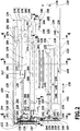
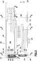
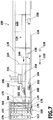
- One in the Fig. 1 to 9 illustrated, as a whole with 100 designated paint shop for painting vehicle bodies 102 includes a plurality of treatment areas for surface treatment of the vehicle bodies 102, which on a in Fig. 1 illustrated first conveyor level 104 and on a in Fig. 2 arranged second conveying level 106 are arranged and through which the vehicle bodies to be treated 102 are successively conveyed through.
- Each treatment area is assigned to a process section of the paint shop 100, which ends in one of three high-bay warehouses 108, 110 or 112 of the paint shop 100 serving as temporary storage 107 and / or begins in one of these high-bay warehouses 108, 110 or 112.
- the three high-bay warehouse 108, 110 and 112 are at one in the Fig. 1 to 3 left illustrated first end face 114 of a designated as a whole 116 building shell of the paint shop 100.
- the building shell 116 of the paint shop 100 further includes a first end face 114 opposite the second end face 118 and two the two end faces 114 and 118 interconnecting longitudinal sides 120 and 122 and a horizontal floor 124 and a horizontal ceiling wall 126 (see the Fig. 4 and 5 ).
- the end faces 114 and 118 of the painting installation 100 extend essentially along a horizontal transverse direction 128 of the painting installation 100, while the longitudinal sides 120 and 122, formed longer than the end faces 114 and 118, essentially follow a horizontal longitudinal direction 130 extending perpendicular to the transverse direction 128 Paint shop run.
- the end faces 114, 118, the longitudinal sides 120, 122, the floor 124 and the top wall 126 of the building envelope 116 of the paint shop 100 jointly enclose a building interior 132, in which the treatment areas and the high-bay warehouses 108, 110, 112 of the paint shop 100 are arranged which the vehicle bodies 102 are successively conveyed along a conveying path 134.
- the conveying path 134 of the vehicle bodies 102 through the paint shop 100 begins at an entrance 136, which is located on the in Fig. 2 shown second conveyor level 106 is located. At this point, the vehicle bodies 102 enter the paint shop 100 from a body shop that precedes the paint shop 100.
- a pretending facility 138 with pretreatment immersion basins 140 extends in the longitudinal direction 130 of the painting installation 100 in the direction of the first end face 114.
- the pretreatment line 138 is adjoined by a turning region 142, in which the conveying direction 144 of the vehicle bodies 102 is rotated through 180 °.
- a KTL system 146 ("KTL” stands for "cataphoretic dip painting") with at least one cathodic dip tank 148 adjoins the turning region 142, which extends in the longitudinal direction 130 of the painting installation 100 in the direction of the second end face 118.
- substantially cylindrical counter containers 149 to the pretreatment dip tank 140 are disposed on the first conveyor level 104 adjacent to the pretreatment dip tank 140.
- two, counter containers 151 to the KTL dip tank 148 are arranged on the first conveyor level 104 adjacent to the turning area 142.
- the KTL system 146 is followed by a further turning region 150, in which the conveying direction 144 of the vehicle bodies 102 is again rotated by 180 °.
- the conveying path 134 of the vehicle bodies 102 branches into two continuous-flow dryers 152, which extend parallel to one another in the longitudinal direction 130 in the direction of the first end face 114 and terminate in a respective cooling zone 154.
- a supply / exhaust system 155 for the relevant cooling zone 154 is arranged (see Fig. 7 ).
- each of the KTL continuous drier 152 is each a plurality of heating units 156 are arranged, which are located on the first conveyor level 104 and on the floor 124 of the building envelope 116 are (see Fig. 5 ).
- These heaters 156 provide heated supply air which is fed to the dryer tunnels of the KTL continuous dryers 152.
- a transverse conveyor 158 follows alternately onto the cooling zones 154 of the KTL continuous driers 152, which alternately conveys vehicle bodies 102 out of the two cooling zones 154 to a pivoting table 160 on which the vehicle bodies 102 are pivoted by 90 ° about a vertical axis, so that they are then no longer aligned parallel to the longitudinal direction 130, but parallel to the transverse direction 128 of the paint shop 100.
- the vehicle bodies 102 pass through one of two entrance tunnels 162 into the first high-bay warehouse 108, which is separated from the building interior 132 by an airtight housing 164.
- the high-bay warehouse 108 comprises two storage shelves 166 extending parallel to the transverse direction 128 of the paint shop 100 for vehicle bodies 102, which are separated from one another by a corridor 168 in which two storage and retrieval units 170 are movably arranged along the transverse direction 128.
- Each of the storage shelves 166 has a plurality of body storage compartments 171 juxtaposed in a plurality of vertical columns 172 and juxtaposed in a plurality of horizontal rows 174 (see FIGS Fig. 6 ).
- Two of the compartments on the second conveyor level 106 serve as storage positions 176 for the first high-bay warehouse 108; In these positions, the vehicle bodies 102 are conveyed through the entrance tunnels 162.
- one of the two storage and retrieval units 170 takes over a conveyed vehicle body 102 from one of these storage positions 176 and transports the vehicle body 102 for temporary storage in a free body storage compartment 171.
- the subject vehicle body 102 is removed from its body storage compartment 171 and transported by a storage and retrieval device 170 to one of two removal positions 178, which are located at the level of the first delivery level 104 of the paint shop 100.
- the vehicle bodies 102 on the first conveyor level 104 are replaced by exit tunnels 180 (see FIG Fig. 1 ) are conveyed from the first high-bay warehouse 108 out to pivot tables 182, on which the orientation of the vehicle bodies 102 is rotated by 90 ° about a vertical axis, so that the vehicle bodies 102 are aligned again parallel to the longitudinal direction 130 of the paint shop 100.
- the pretreatment plant 138, the KTL plant 146 and the KTL continuous dryers 152 with the cooling zones 154 together form a first process section 184 of the paint shop 100, which begins at the entrance 136 of the paint shop 100 on the second conveyor level 106 and at the entrance tunnels 162 of the first high-bay warehouse 108 on the second conveyor level 106 ends.
- the treatment areas of the first process section 184 are all located on the second conveyor level 106.
- the conveying path 134 of the vehicle bodies 102 extends in two parallel lines in the longitudinal direction 130 of the painting installation 100 in the direction of the second end face 118 through a series of open treatment areas or workstations, namely through a respective KTL Control area 186, each having a Nahtabdicht area 188, each by an underbody protection coating system 190 and by a respective Feinabdicht Scheme 192 to a cross conveyor 193 and a lifting system 194th
- Underbody protection coating equipment 190 includes both underbody protection application booths 191 (see Fig. 5 ) as well as the building interior 132 open towards treatment areas and jobs.
- the lifting plant 194 conveys the vehicle bodies 102 from the in Fig. 1 shown first delivery level 104 on the in Fig. 2 illustrated second conveyor level 106.
- On the second conveyor level 106 connects to the lifting system 194 a turning area 196 with two pivoting tables 198, in which the orientation of the vehicle bodies 102 is rotated by 90 ° about a vertical axis, so that the vehicle bodies 102 in the turning area 196 are rotated by a total of 180 °.
- the turning area 196 is adjoined by a cleaning cabin 200 and a filler spraying booth 202, in which the vehicle bodies 102 are provided with a coating of a filler material by means of spraying robots.
- the conveying path 134 of the vehicle bodies 102 branches off into two filler through-dryers 204 extending parallel to the longitudinal direction 130 of the painting installation 100 onto the first end face 114, which terminate in a respective cooling zone 206.
- a paint mist scrubber 208 is disposed, which is located on the first conveyor level 104 and stands on the floor 124 of the building envelope 116.
- a Zuluft plenum 210 is disposed above the filler spray booth 202.
- Zuluf plenum 210 of the underlying filler spray booth 202 is fed to a supply air, which receives in the filler spray booth 202 paint overspray, which is washed out of the air flow in the below the filler spray booth 202 paint mist scrubber 208.
- 204 heaters 212 are provided for producing the warm air to be supplied to the once-through dryers 204 among the once-through dryers.
- the heating units 212 are located on the first conveyor level 104 of the paint shop 100 and stand on the floor 124 of the building envelope 116.
- Adjoining the cooling zones 206 of the filler through-flow dryer 204 in the conveying path 134 of the vehicle bodies 102 is a transverse conveyor 214, by means of which the vehicle bodies 102 can be conveyed to a lifting installation 216 after passing through the cooling zones 206.
- the lifting plant 216 conveys the vehicle bodies 102 from the second conveying level 106 to an in Fig. 3 illustrated third conveying level 218 of the paint shop 100th
- the third conveying level 218 is above the second conveying level 106, which in turn lies above the first conveying level 104.
- the third conveyor level 218 is at a height of approximately 7.5 m above the floor 124, while the second conveyor level 106 is at a height of approximately 5.0 m above the floor 124 and the first conveyor level 104 at the level of the floor 124 ,
- the vehicle bodies 102 are conveyed to a pivoting table 220, which rotates the vehicle bodies 102 through an angle of 90 ° about a vertical pivot axis, so that the vehicle bodies 102 are then aligned parallel to the transverse direction 128 of the painting installation 100.
- the vehicle bodies 102 are each conveyed to one of two entrance tunnels 222 of the second high bay warehouse 110.
- the vehicle bodies 102 reach two storage positions 224 of the second high-bay warehouse 110 (see FIG Fig. 6 ), which are at the level of the third conveying level 218.
- the vehicle bodies 102 are transported by means of two storage and retrieval units 170 of the second high-bay warehouse 110 into a free body storage compartment 171 and deposited there.
- the same is transported from its body storage compartment 171 by means of one of the stacker cranes 170 to one of two storage positions 226 of the second high-bay warehouse 110, which are at the level of the second delivery level 106 of the paint shop 100.
- the vehicle bodies 102 are conveyed out of the second high-bay warehouse 110 by one of two output tunnels 228 (see FIG Fig. 2 ).
- the KTL control areas 186, the seam sealing areas 188, the underbody protection coating installations 190, the fine sealing areas 192, the cleaning cabin 200, the filler spray booth 202 and the filler passage dryers 204 with their cooling zones 206 belong to a second process section 230 of the paint shop 100 which starts at the first high-bay warehouse 108 on the first conveyor level 104 and ends at the second high-bay warehouse 110 on the third conveyor level 218.
- the CTL control areas 186, seam sealing areas 188, underbody protection coating systems 190, and fine sealing areas 192 are located on the first conveyor level 104, while the cleaning booth 200, filler spray booth 202, and filler pass-through dryers 204 have their cooling zones 206 located on the second conveyor level 106.
- All treatment areas of the second process section 230 are thus located on the first conveyor level 104 or on the second conveyor level 106 of the paint shop 100.
- the second high-bay warehouse 110 like the first high-bay warehouse 108 and the third high-bay warehouse 112 to be described later, is designed as a clean-room area.
- each of the high-bay warehouse is enclosed by an airtight housing 164 which separates the interior of the high-bay warehouse from the building interior 132 of the building shell 116, so that no contaminants from the building interior 132 can reach the interior of the housing 164 of the respective high-bay warehouse.
- the interior of the housing 164 of the high-bay warehouse is accessible only via the respective entrance tunnels 162, 222 and via the respective exit tunnels 180, 228.
- each high-bay warehouse is separated by means of an in Fig. 9 shown Um Kunststoffstrom 232 under an overpressure of at least about 100 Pa, preferably set of at least about 50 Pa, relative to the air pressure in the building interior 132.
- the recirculation system 232 includes a supply air device 234 with a fan 236, which sucks air from the building interior 132 through a suction port 238 and through an air filter 240 into an air supply line 242 promotes.
- the air supply line 242 branches into a plurality, for example three, supply air channels 244, which extend in a vertical direction along an end wall 246 of a high-bay warehouse (see FIG Fig. 6 ).
- the supply air exits through vertically arranged one above the other inlet air openings 248 of the supply air ducts 244 in the interior 258 of the high-bay warehouse.
- one or more exhaust ducts 250 are provided, which also extend in a vertical direction along a boundary wall of the housing 164 of the respective high-bay warehouse and have vertically disposed exhaust openings 252 through which air from the interior 258 of the housing 164 of the high-bay warehouse in an in Fig. 9 shown exhaust pipe 254 is sucked.
- the two high-bay warehouses 110 can, as in Fig. 6 can be arranged in a common housing 164, so that air can pass unhindered from the first high-bay warehouse 108 to the second high-bay warehouse 110 or in the reverse direction.
- each of the high-bay warehouse 108, 110 has its own housing 164, which is airtight separated from the housing of the other high-bay warehouse.
- each input tunnel of a high-bay warehouse such as the entrance tunnel 222 of the second high-bay warehouse 110, an entrance lock 256, in which supply air from the pressurized interior 258 of the housing 164 of the high-bay warehouse, for example, the second high-bay warehouse 110, flows.
- This inflowing supply air prevents air from the building interior 132 passes through the entrance tunnel 222 into the interior 258 of the housing 164.
- the exhaust air line 254 opens on the suction side of the blower 236 in the supply air device 234 of the recirculation system 232, so that the recirculation circuit is closed by the Zuluft réelle 234 through the interior 258 of the housing 164 of the high-bay warehouse and optionally through the entrance lock 256 of the high-bay warehouse.
- the entrance tunnels of the other high-bay warehouses, as well as the entrance tunnels 222 of the second high-bay warehouse 110, are provided with an intake lock 256 through which air circulates.
- exit tunnels of all high-bay warehouses are also provided with a suitably designed exit lock.
- each body storage compartment 171 is provided with a cover 264 arranged above the respective storage space for a vehicle body 102 (see FIG Fig. 6 ).
- This cover 264 may in particular be formed as a protective film of a suitable plastic material, for example of polyethylene.
- the protective film used as cover 264 complies with the applicable fire protection regulations.
- cover 264 By means of the cover 264, it is prevented, in particular, that impurities from the storage and retrieval device 170 or from a vehicle body transport kit, on which a vehicle body 102 is arranged, are arranged in a storage body 171 disposed above a body storage compartment 171 during a storage or removal process of a vehicle body 102 is, on a stored in the lower body storage compartment 171 vehicle body 102 can fall down.
- the vehicle bodies 102 on the second conveyance level 106 become one each Pivoting table 266 which pivots the vehicle bodies 102 by an angle of 90 ° about a vertical pivot axis, so that the vehicle bodies 102 are then aligned parallel to the longitudinal direction 130 of the paint shop 100.
- the vehicle bodies 102 on the second conveyor level 106 of the paint shop 100 are conveyed to a cross conveyor 268, which distributes the vehicle bodies 102 to two top coat lines 270.
- topcoat preparation booth 272 In each of these topcoat lines 270, in the conveying path 134 of the vehicle bodies 102, a topcoat preparation booth 272, several basecoat spray booths 274 and an intermediate pass dryer 276 follow each other, all of which extend in the longitudinal direction 130 of the paint shop 100 onto the second end face 118.
- a paint mist scrubbing system 208 is disposed under each basecoat spray booth 274, which is located on the first conveyor level 104 and is on the floor 124 of the building envelope 116.
- a supply air plenum 210 is arranged above each basecoat spray booth 274.
- each topcoat line 270 is adjoined in each case by a turning region 278 in the form of an air lock, in which the orientation of the vehicle bodies 102 is rotated by an angle of 180 °.
- paint mist scrubbing systems 208 are arranged under the clearcoat spray booths 282, which are located on the first conveyor level 104 of the paint shop 100 and stand on the floor 124 of the building envelope 116.
- each a Zu Kunststoff plenum 210 is arranged.
- a plurality of heating units 290 are each arranged under the top coat continuous dryers 286, which are located on the first conveyor level 104 of the paint shop 100 and stand on the floor 124 of the building envelope 116.
- the vehicle bodies 102 are conveyed to a respective pivoting table 292, which pivots the vehicle bodies 102 through an angle of 90 ° about a vertical axis, so that the vehicle bodies 102 are then aligned parallel to the transverse direction 128 of the painting installation 100.
- the vehicle bodies 102 are each conveyed on the second conveyor level 106 to the third high-bay warehouse 112 of the paint shop 100 by one of two entrance tunnels 294, which are each provided with an entry lock.
- the vehicle bodies 102 are transported by means of stacker cranes 170 to body storage compartments 171 of the third high-bay warehouse 112.
- the vehicle bodies 102 for further processing by means of the stacker cranes 170 are transported to storage positions of the third high-bay warehouse 112 at the level of the first conveying level 104 of the paint shop 100.
- the third high-bay warehouse 112 is arranged in the longitudinal direction 130 of the paint shop 100 behind the second high-bay warehouse 110 on the first end face 114 of the building shell 116 and thus between the first end face 114 and the second high-bay warehouse 110.
- the vehicle bodies 102 pass through exit tunnel 296 of the third high-bay warehouse 112, which each comprise an exit lock, on the first conveyor level 104 of the paint shop 100 (see FIG Fig. 1 ) to a respective transverse conveyor 298.
- topcoat lines 270 with topcoat preparation booths 272, basecoat spray booths 274, intermediate pass dryers 276, cooling zones 280, clearcoat spray booths 282, evaporator zones 284, and topcoat pass dryers 286 with cooling zones 288 belong to one
- the third process section 300 of the paint shop 100 which starts at the exit tunnels 228 of the second high-bay warehouse 110 on the second conveyor level 106 of the paint shop 100 and ends at the entrance tunnels 294 of the third high-bay warehouse 112 on the second conveyor level 106 of the paint shop 100.
- topcoat lines 270 with topcoat preparation booths 272, basecoat spray booths 274, intermediate pass dryers 276, cooling zones 280, clearcoat spray booths 282, evaporator zones 284, and topcoat pass dryers 286 with the cooling zones 288, are located on the second conveyor level 106 of the paint shop 100th
- the third high-bay warehouse 112 is designed as a clean-room area which is separated from the building interior 132 of the building envelope 116.
- the vehicle bodies 102 From the transverse conveyors 298 on the first conveying level 104 of the painting installation 100, the vehicle bodies 102 reach pivoting tables 302, which pivot the vehicle bodies 102 through an angle of 90 ° about a vertical axis, so that the vehicle bodies 102 subsequently again parallel to the longitudinal direction 130 of the painting installation 100 are aligned.
- the vehicle bodies 102 on the first conveyor level 104 of the paint shop 100 are each conveyed through one of two finishing and inspection areas 304.
- the finishing and inspection areas 304 are adjoined in the conveying path 134 of the vehicle bodies 102 by a transverse conveyor 306, which conveys the vehicle bodies 102 to an exit 308 of the painting installation 100, from where the finished painted vehicle bodies 102 reach a final assembly installation.
- a rework on a vehicle body 102 is required, it is conveyed by the cross conveyor 306 to a rework feed conveyor 319, from where the relevant vehicle body 102 passes via a cross conveyor 314 in a rework preparation area 312.
- the vehicle body 102 is conveyed via a transverse conveyor 310 and an adjoining lifting installation 317 to the inlet of one of the topcoat preparation booths 272 on the second conveyor level 106, in order subsequently to be painted again.
- the completion and inspection areas 304 and the rework preparation area 312 belong to a fourth process section 316 of the paint shop 100, which starts at the exit tunnels 296 of the third high bay warehouse 112 on the first conveyor level 104 and at the exit 308 of the paint shop 100 at the first conveyor level 104 of the paint shop 100 ends.
- All treatment areas of the fourth process section 316 i. the completion-and-inspection areas 304 and the rework preparation area 312 are located on the first conveyance level 104 of the paint shop 100.
- Fig. 1 is located on the first conveying level 104 of the paint shop 100 also has a color mixing chamber 318 which is disposed between the Feinabdicht Schemee 192 of the second process section 230 and the second end face 118 of the building envelope 116.
- supply air systems 320 on the first delivery level 104, which serve to supply the supply air plenums 210 of the filler spray booths 202, the basecoat spray booths 274 and the clearcoat spray booths 282 and between the paint mist scrubbers 208 of these spray booths on the one hand and the second end face 118 of the building envelope 116 on the other hand are arranged.
- the supply air systems 320 are via supply air channels 321 (see Fig. 8 ) connected to the respective associated Zu Kunststoff plenen 210 spray booths.
- a paint sludge disposal area 322 is further provided on the first conveying level 104 of the paint shop 100, which serves for the further processing of paint scrubber scrubbed by the paint mist scrubbers 208 from the booth exhaust air and between the air supply systems 320 on the one hand and the paint mist scrubbers 208 on the other hand is arranged.
- the paint sludge disposal area 322 may include lacquer coagulation plants 323 for water lacquer and / or lacquer coagulation plants 325 for solvent-based lacquer arranged underneath the floor 124 of the building shell 116.
- an exhaust air system 324 Adjacent to the supply air systems 320, an exhaust air system 324 is arranged outside the building shell 116 on the second end face 118 of the building shell 116, which sucks exhaust air from the spray booths via exhaust ducts 327 arranged below the floor 124 of the building shell 116 and discharges them to an exhaust air chimney 326.
- the supply air systems 320 all lie within a substantially rectangular, contiguous region 328 of the first delivery level 104, in which no other process devices of the paint shop 100 are arranged.
- the paint mist scrubbers 208 are located in a substantially rectangular, contiguous region of the first conveyor level 104, designated 330, in which no other process devices of the paint shop 100 are arranged.
- the heating units 156 of the KTL continuous driers 152 all lie in a substantially rectangular, contiguous region 331 of the first conveying level 104 of the painting installation 100, in which no other process devices of the painting installation 100 are arranged.
- the heating units 212 of the filler pass-through dryers 204 likewise all lie in a substantially rectangular, contiguous region 332 of the first conveying level 104 of the painting installation 100, in which no other process devices of the painting installation 100 are arranged.
- the heating units 290 of the top coat continuous dryers 286 are each located in a substantially rectangular, contiguous region 333 of the first conveying level 104 of the paint shop 100, in which no other process devices of the paint shop 100 are arranged.
- the clear structure of the first conveying level 104 of the painting installation and the combination of similar process devices in the respective contiguous areas 328, 330, 331, 332 and 333 of the first conveying level 104 ensure that areas for open workplaces, machine areas and process areas do not overlap one another and in particular that the radiation of heat from the heating units 156, 212 and 290 of the continuous dryers does not adversely affect the other process devices and workplaces.
- the ceiling wall 126 of the building envelope 116 is supported by vertical supports 334 which extend from the floor 124 of the building envelope 116 to the ceiling wall 126.
- each support 334 is provided below the bottom 124.
- a concrete foundation 336 is provided in the area of each support 334.
- the vehicle bodies 102 are thereby suspended on an overhead conveyor conveyed through, wherein the vehicle bodies 102 are immersed by a lowering of the suspension conveyor track from the second conveyor level 106 in said plunge pools.
- the vehicle bodies 102 could also be conveyed to swivel brackets by the first process section 184, with the vehicle bodies 102 immersed in the plunge pools 140 and 148 of the first process section 184 by rotation about a horizontal axis from the second conveyor level 106 and through another rotation around this axis can be dipped out of this basin again.
- the vehicle bodies 102 pass into the first high-bay warehouse 108 into which the vehicle bodies 102 are conveyed on the second conveyor level 106 and out of which the vehicle bodies 102 on the first conveyor level 104 are again conveyed out.
- the vehicle bodies 102 Before leaving the first high-bay warehouse 108, the vehicle bodies 102 may be stored in a body storage compartment 171.
- the vehicle bodies 102 may be paged out of the first high bay warehouse 108 in a paging order different from the piling order, so that the handling order of the vehicle bodies 102 between the first process section 184 and the second process section 230 may be changed.
- color blocks can be formed for the subsequent painting and / or reworking bodies can be sorted in a streamlined manner.
- the transport of the vehicle bodies 102 from the second conveying level 106 to the first conveying level 104 takes place within the first high-bay warehouse 108, by means of the stacker cranes 170.
- the vehicle bodies 102 After leaving the first high-bay warehouse 108 on the first conveyor level 104, the vehicle bodies 102 are sealed in the second process section 230 of the paint shop 100, provided with underbody protection, then raised from the first conveyor level 104 to the second conveyor level 106 and on the second conveyor level 106 with a filler painted, which is then dried.
- the vehicle bodies 102 are lifted from the second conveying level 106 to the third conveying level 218 of the painting installation and conveyed into the second high-bay warehouse 110.
- a change in the treatment sequence of the vehicle bodies 102 can be carried out in the second high-bay warehouse 110 as well as in the first high-bay warehouse 108.
- the transport of the vehicle bodies 102 from the third conveyor level 218 to the second conveyor level 106 of the paint shop 100 takes place within the second high-bay warehouse 110 by means of the stacker cranes 170.
- the vehicle bodies 102 After the vehicle bodies 102 have left the second high-bay warehouse 110 on the second conveyor level 106, they are prepared in the third process section 300 of the paint shop 100 for the topcoat, for example by grinding, and then provided with a basecoat.
- the base coat is intermediately dried before the vehicle bodies 102 are painted with clearcoat and the entire topcoat is dried.
- the coating with base coat and clear coat can be done by means of spray robots or manually or partially by means of spray robots and partially manually.
- the vehicle bodies 102 are conveyed on the second conveying level 106 into the third high-bay warehouse 112.
- the vehicle bodies 102 Before the vehicle bodies 102 are conveyed out of the third high-bay warehouse 112 on the first conveyor level 104, they can be stored temporarily in body storage compartments 171 of the third high-bay warehouse 112.
- the treatment sequence of the vehicle bodies 102 in the third high-bay warehouse 112 can be changed in the same way as in the first high-bay warehouse 108 and in the second high-bay warehouse 110.
- the vehicle bodies 102 are transported in the third high-bay warehouse 112 by means of the stacker cranes 170 of the third high-bay warehouse 112 from the second conveyor level 106 to the first conveyor level 104.
- the vehicle bodies 102 in the fourth process section 316 of the paint shop 100 are completed and checked, optionally reworked and finally transferred at the outlet 308 of the paint shop 100 to a subsequent final assembly facility.
- Most of the treatment areas arranged on the first conveyor level 104 of the paint shop 100, in particular the seam sealing areas 188, the open spaces of the underbody coating systems 190, the fine sealing areas 192, the completion and inspection areas 304 and the rework preparation area 312 are open treatment areas and open workplaces leading to the building interior 132 of the Building shell 116 open and not separated by partitions of the building interior 132.
- Cooling zones 288 are closed treatment areas which are separated from the building interior 132 of the building envelope by cabin or dryer walls.
- the transport of the vehicle bodies 102 through the pretreatment plant 138, the cathodic dip-painting installation 146 and the underbody protection coating installations 190 can be effected by means of overhead conveyors, the transport of the vehicle bodies 102 through the remaining open or closed treatment areas and between the treatment areas and to and from the high-bay warehouses 108, 110 and 112 can be done by means of roller conveyors.
- the transport of the vehicle bodies 102 from one of the high-bay stores 108 or 110 into the respectively subsequent high-bay store 110 or 112 always takes place via the respective intermediate process section 230 or 300; a direct transport of vehicle bodies 102 from one of the high-bay warehouse to another high-bay warehouse or a return transport of vehicle bodies 102 against the passage direction of the conveying path 134 are not provided.
Landscapes
- Life Sciences & Earth Sciences (AREA)
- Engineering & Computer Science (AREA)
- Wood Science & Technology (AREA)
- Details Or Accessories Of Spraying Plant Or Apparatus (AREA)
- Application Of Or Painting With Fluid Materials (AREA)
- Coating Apparatus (AREA)
- Spray Control Apparatus (AREA)
- Automobile Manufacture Line, Endless Track Vehicle, Trailer (AREA)
- Warehouses Or Storage Devices (AREA)
- Management, Administration, Business Operations System, And Electronic Commerce (AREA)
Claims (16)
- Installation de mise en peinture (100) pour la mise en peinture d'objets à peindre qui se présentent sous forme de carrosseries de véhicules (102) et/ou d'éléments de carrosseries de véhicules, comprenant :- une enveloppe de bâtiment (116) qui entoure un espace intérieur de bâtiment (132) dans lequel sont disposées au moins une cuve d'immersion (140, 148) et au moins une zone de traitement ouverte (188, 190, 192, 304, 312), laquelle est ouverte par rapport à l'espace intérieur du bâtiment ;- un premier niveau de transport (104) sur lequel des objets à peindre peuvent être acheminés à travers au moins une zone de traitement ouverte (188, 190, 192, 304, 312) ;- un second niveau de transport (106) à partir duquel des objets à peindre peuvent être immergés dans au moins une cuve d'immersion (140, 148) ;
et- au moins un système de stockage intermédiaire (107), au moins un objet à peindre pouvant être transporté d'un niveau de transport (104, 106) de l'installation de mise en peinture (100) dans le système de stockage intermédiaire (107) et, ultérieurement, dudit stockage intermédiaire (107) vers un autre niveau de transport (106, 104) de l'installation de mise en peinture (100),caractérisée en ce que le premier niveau de transport (104) se trouve sous le deuxième niveau de transport (106). - Installation de mise en peinture (100) selon la revendication 1, caractérisée en ce que le système de stockage intermédiaire (107) comporte plusieurs cases de stockage (171), pouvant être occupées facultativement par des objets à peindre.
- Installation de mise en peinture (100) selon la revendication 1 ou la revendication 2, caractérisée en ce que le système de stockage intermédiaire (107) est conçu sous forme de système de stockage de grande hauteur (108, 110, 112).
- Installation de mise en peinture (100) selon l'une quelconque des revendications 1 à 3, caractérisée en ce que les objets à peindre peuvent être acheminés sur le deuxième niveau (106) à travers au moins un sécheur (152, 204, 276, 286).
- Installation de mise en peinture (100) selon l'une quelconque des revendications 1 à 4, caractérisée en ce que les objets à peindre peuvent être acheminés sur le deuxième niveau (106) à travers au moins une cabine d'application de peinture par pulvérisation (202, 274, 282).
- Installation de mise en peinture (100) selon l'une quelconque des revendications 1 à 5, caractérisée en ce que les objets à peindre peuvent être acheminés sur le premier niveau (104) à travers au moins une installation de revêtement pour la protection de bas de caisse (190).
- Installation de mise en peinture (100) selon l'une quelconque des revendications 1 à 6, caractérisée en ce qu'au moins un dispositif de séparation (208), destiné à la séparation du brouillard de peinture depuis l'air vicié d'une cabine d'application de peinture par pulvérisation (202, 274, 282) et/ou au moins un dispositif pour l'élimination de boues de peinture (322) est/sont disposés sur le premier niveau de transport (104).
- Installation de mise en peinture (100) selon l'une quelconque des revendications 1 à 7, caractérisée en ce qu'au moins une installation d'amenée d'air (320) est disposée sur le premier niveau de transport (104) pour alimenter en air frais au moins une cabine d'application de peinture par pulvérisation (202, 274, 282).
- Installation de mise en peinture (100) selon l'une quelconque des revendications 1 à 8, caractérisée en ce que l'installation de mise en peinture (100) comporte au moins un système d'évacuation (324) pour l'évacuation d'air vicié à l'extérieur d'au moins une cabine d'application de peinture par pulvérisation (202, 274, 282), le système d'évacuation (324) étant disposé à l'extérieur de l'enveloppe de bâtiment (116) à hauteur du premier niveau de transport (104).
- Installation de mise en peinture (100) selon l'une quelconque des revendications 1 à 9, caractérisée en ce qu'au moins un groupe de chauffage (156, 212, 290) est disposé sur le premier niveau de transport (104) pour chauffer au moins un sécheur (152, 204, 276, 286).
- Installation de mise en peinture (100) selon l'une quelconque des revendications 1 à 10, caractérisée en ce que tous les appareils de traitement de l'installation de mise en peinture (100) sont installés depuis le premier niveau de transport (104).
- Installation de mise en peinture (100) selon l'une quelconque des revendications 1 à 11, caractérisée en ce qu'elle comprend au moins deux systèmes de stockage intermédiaire (107) au moyen desquels des objets à peindre peuvent être transportés d'un niveau de transport (104, 106, 218) de l'installation de mise en peinture (100) sur un autre niveau de transport (218, 106, 104) de l'installation de mise en peinture (100).
- Installation de mise en peinture (100) selon l'une quelconque des revendications 1 à 12, caractérisée en ce que chaque appareil de traitement de l'installation de mise en peinture (100) est disposé soit sur le premier niveau de transport (104) soit sur une structure s'étendant vers le haut depuis un plancher (124) de l'enveloppe de bâtiment (116) disposé sur le premier niveau de transport (104).
- Installation de mise en peinture (100) selon l'une quelconque des revendications 1 à 13, caractérisée en ce qu'au moins un système de stockage intermédiaire (107) est disposé directement au voisinage d'un mur (114) de l'enveloppe de bâtiment (116).
- Installation de mise en peinture (100) selon l'une quelconque des revendications 1 à 14, caractérisée en ce que tous les appareils de traitement de l'installation de mise en peinture (100) sont disposés sur le premier niveau de transport (104) ou sur le deuxième niveau de transport (106) de l'installation de mise en peinture (100).
- Installation de mise en peinture (100) selon l'une quelconque des revendications 1 à 15, caractérisée en ce que des cases de stockage (171) du système de stockage intermédiaire (107) destinées aux objets à peindre sont pourvues chacune d'un capot (264) disposé directement au-dessus de l'objet à peindre en question, le capot (264) comprenant un film de protection fabriqué dans une matière synthétique.
Priority Applications (1)
| Application Number | Priority Date | Filing Date | Title |
|---|---|---|---|
| PL09780667T PL2303468T3 (pl) | 2008-07-29 | 2009-07-15 | Lakiernia do lakierowania elementów przeznaczonych do lakierowania |
Applications Claiming Priority (2)
| Application Number | Priority Date | Filing Date | Title |
|---|---|---|---|
| DE102008036321A DE102008036321A1 (de) | 2008-07-29 | 2008-07-29 | Lackieranlage zum Lackieren von zu lackierenden Gegenständen |
| PCT/EP2009/059104 WO2010012600A1 (fr) | 2008-07-29 | 2009-07-15 | Installation de mise en peinture pour la mise en peinture d'objets à peindre |
Publications (2)
| Publication Number | Publication Date |
|---|---|
| EP2303468A1 EP2303468A1 (fr) | 2011-04-06 |
| EP2303468B1 true EP2303468B1 (fr) | 2017-02-15 |
Family
ID=41212335
Family Applications (1)
| Application Number | Title | Priority Date | Filing Date |
|---|---|---|---|
| EP09780667.3A Active EP2303468B1 (fr) | 2008-07-29 | 2009-07-15 | Installation de mise en peinture pour la mise en peinture d'objets à peindre |
Country Status (11)
| Country | Link |
|---|---|
| US (1) | US9592522B2 (fr) |
| EP (1) | EP2303468B1 (fr) |
| JP (1) | JP5635505B2 (fr) |
| KR (1) | KR101646502B1 (fr) |
| CN (1) | CN102112239B (fr) |
| DE (1) | DE102008036321A1 (fr) |
| ES (1) | ES2623009T3 (fr) |
| HU (1) | HUE033125T2 (fr) |
| PL (1) | PL2303468T3 (fr) |
| RU (1) | RU2508167C2 (fr) |
| WO (1) | WO2010012600A1 (fr) |
Families Citing this family (16)
| Publication number | Priority date | Publication date | Assignee | Title |
|---|---|---|---|---|
| KR101554890B1 (ko) * | 2008-04-16 | 2015-09-22 | 단프로텍스 에이/에스 | 물품의 함침을 위한 방법 및 장치 |
| DE102008036321A1 (de) | 2008-07-29 | 2010-02-04 | Dürr Systems GmbH | Lackieranlage zum Lackieren von zu lackierenden Gegenständen |
| CN102327836B (zh) * | 2011-08-18 | 2013-08-14 | 无锡市精盛汽车配件有限公司 | 汽车灯罩装饰框喷涂处理线系统 |
| US8646404B2 (en) * | 2011-09-26 | 2014-02-11 | Todd E. Hendricks, SR. | Modular system with platformed robot, booth, and fluid delivery system for tire spraying |
| CN103010697B (zh) * | 2012-12-20 | 2015-05-27 | 江苏速升自动化装备股份有限公司 | 超长重型工件的电泳油漆生产输送系统 |
| CN105521916B (zh) * | 2016-01-14 | 2018-07-06 | 江西格林自动化设备有限公司 | 一种用于圣诞树枝自动上漆设备 |
| DE102017000640B4 (de) | 2017-01-25 | 2018-12-20 | Audi Ag | Beschichtungsanlage und Verfahren zum Betreiben einer Beschichtungsanlage |
| CN107758186B (zh) * | 2017-08-28 | 2019-05-21 | 常熟冠林汽车饰件有限公司 | 汽车饰件自动化仓储及喷涂一体化设备的工作控制方法 |
| CN107745904B (zh) * | 2017-08-28 | 2019-05-21 | 常熟冠林汽车饰件有限公司 | 汽车饰件自动化仓储及喷涂一体式设备 |
| CN107745905A (zh) * | 2017-08-28 | 2018-03-02 | 常熟冠林汽车饰件有限公司 | 汽车饰件自动化仓储及喷涂一体式设备的码垛装置 |
| CN107792642B (zh) * | 2017-08-28 | 2019-05-21 | 常熟冠林汽车饰件有限公司 | 汽车饰件自动化仓储及喷涂的面漆喷房工作控制方法 |
| DE102018115235A1 (de) * | 2018-06-25 | 2020-01-02 | Eisenmann Se | Durchlauftrockenanlage und Verfahren zum Trocknen von Werkstücken |
| ES1254126Y (es) * | 2020-04-17 | 2021-01-11 | Das Tech Solutions S L U | Aplicadora modular de producto sobre material laminar |
| CN111921767B (zh) * | 2020-07-31 | 2022-06-21 | 山东中亚车业有限公司 | 一种水性涂料涂覆流水线 |
| EP4277766A1 (fr) * | 2021-01-12 | 2023-11-22 | ABB Schweiz AG | Chaîne de production, chariot et procédé de traitement |
| CN115106244B (zh) * | 2022-06-14 | 2024-03-12 | 神华准格尔能源有限责任公司 | 浸漆吸风系统 |
Citations (14)
| Publication number | Priority date | Publication date | Assignee | Title |
|---|---|---|---|---|
| US3824952A (en) | 1972-10-05 | 1974-07-23 | Riken Light Metal Ind Co | Finish dip painting device of metal works on mass production basis |
| US4770122A (en) | 1986-02-13 | 1988-09-13 | Mazda Motor Corporation | Arrangements for sorting vehicle bodies by the colors of coating expected thereon in a vehicle body coating line |
| US4831962A (en) | 1985-10-18 | 1989-05-23 | Societe Industrielle D'equiptment Technique D'appareils De Manutention | Device for transporting objects which pass within tanks, a method of conveying objects and an installation for treatment of objects |
| JPH1025599A (ja) | 1996-07-09 | 1998-01-27 | Hino Motors Ltd | 電着塗装方法及びその装置 |
| DE19630290A1 (de) | 1996-07-26 | 1998-01-29 | Audi Ag | Anlage zur Oberflächenbehandlung von Gegenständen, insbesondere von Fahrzeugkarosserien |
| JPH1071353A (ja) | 1996-08-30 | 1998-03-17 | Trinity Ind Corp | 塗装設備 |
| US5743962A (en) | 1993-09-30 | 1998-04-28 | Mazda Motor Corporation | Product conveying system for coating and treating surfaces |
| DE19641048C2 (de) | 1996-10-04 | 2000-07-20 | Flaekt Ab | Verfahren zum Ein- und Ausbringen von Werkstücken, insbesondere Fahrzeugkarosserien, Vorrichtung und Anlage zur Oberflächenbehandlung von Werkstücken im Durchlauf |
| WO2002060598A1 (fr) | 2001-01-29 | 2002-08-08 | Eisenmann Maschinenbau Kg (Komplementär: Eisenmann Stiftung) | Installation de traitement, notamment de peinture, d'objets, notamment de carrosseries de vehicules automobiles |
| DE4447818C2 (de) | 1994-12-22 | 2003-11-06 | Eisenmann Kg Maschbau | Verfahren zur Pulverbeschichtung und Lackieranlage zur Durchführung des Verfahrens |
| DE10232402A1 (de) * | 2002-07-17 | 2004-02-12 | Witron Logistik + Informatik Gmbh | Puffersystem |
| EP1657144A1 (fr) | 2002-02-20 | 2006-05-17 | Dürr Systems GmbH | Dispositif pour le traitement de pièces, en particulier de carrosseries |
| EP0980716B1 (fr) | 1998-03-04 | 2007-08-15 | Trinity Industrial Corporation | Materiel de revetement |
| WO2010012600A1 (fr) | 2008-07-29 | 2010-02-04 | Dürr Systems GmbH | Installation de mise en peinture pour la mise en peinture d'objets à peindre |
Family Cites Families (70)
| Publication number | Priority date | Publication date | Assignee | Title |
|---|---|---|---|---|
| US3035507A (en) * | 1960-07-05 | 1962-05-22 | Joseph N Gresham | Down-draft water washed paint spray room |
| US3014602A (en) * | 1960-12-19 | 1961-12-26 | George B Gronvold | Automobile parking and storage apparatus |
| US3033390A (en) * | 1960-12-19 | 1962-05-08 | George B Gronvold | Automobile handling and storage apparatus |
| US3839988A (en) * | 1969-07-30 | 1974-10-08 | Durr O | Apparatus for treating articles by immersion in dip tanks |
| US3845286A (en) * | 1973-02-05 | 1974-10-29 | Ibm | Manufacturing control system for processing workpieces |
| US4237794A (en) * | 1976-01-06 | 1980-12-09 | Southern Pacific Transportation Company | Automobile securement mechanism to freight car |
| US4402765A (en) * | 1982-01-18 | 1983-09-06 | Nihon Parkerizing Co., Ltd. | Method and apparatus for treating steel sheet structures |
| IT1159443B (it) * | 1983-05-19 | 1987-02-25 | Fiat Auto Spa | Impianto di trasporto aereo per scocche di autoveicoli particolarmente per linee di verniciatura per elettroforesi ed elemento porta scocca utilizzabile in tale impianto |
| US4653387A (en) * | 1985-03-29 | 1987-03-31 | Trinity Industrial Corporation | Method of operating an air-feed type spray booth |
| JPS62136402A (ja) * | 1985-12-10 | 1987-06-19 | Mitsubishi Metal Corp | 物品搬送および保管装置 |
| DE3739158A1 (de) * | 1987-11-19 | 1989-06-01 | Albert Blum | Lagersystem mit einer foerdereinrichtung, insbesondere parksystem fuer fahrzeuge |
| JPH01187104A (ja) * | 1988-01-19 | 1989-07-26 | Daifuku Co Ltd | 仕分け払い出し搬送装置 |
| JP2670314B2 (ja) * | 1988-10-25 | 1997-10-29 | マツダ株式会社 | 塗装方法 |
| DZ1422A1 (fr) * | 1989-06-09 | 2004-09-13 | Galva Lorraine | Procédé, enciente et installation pour le revêtement continu/intermittent d'objets par passage desdits objets à travers une masse liquide d'un produitde revêtement. |
| US5194302A (en) * | 1989-08-03 | 1993-03-16 | A. O. Smith Corporation | Manufacturing method for coating vehicle structural frames |
| US5094891A (en) * | 1990-02-02 | 1992-03-10 | A. O. Smith Corporation | Vertical dip thin perimeter manufacturing method and facility for coating vehicle structural components |
| JP3144566B2 (ja) * | 1990-05-08 | 2001-03-12 | マツダ株式会社 | 塗装方法および塗装装置 |
| US5347463A (en) * | 1990-07-03 | 1994-09-13 | Honda Giken Kogyo Kabushiki Kaisha | System and method for line production management |
| JPH04146036A (ja) * | 1990-10-09 | 1992-05-20 | Honda Motor Co Ltd | 自動ラインの搬送システム |
| EP0492663B1 (fr) * | 1990-12-28 | 1996-04-03 | Mazda Motor Corporation | Méthode pour l'assemblage des véhicules automobiles |
| JPH0510049A (ja) * | 1991-02-04 | 1993-01-19 | Taisei Corp | 立体駐車場 |
| US5255806A (en) * | 1991-05-03 | 1993-10-26 | Stoughton Composites, Inc. | Reinforced plastic composite intermodal vehicle hauler |
| TW237435B (fr) * | 1992-01-21 | 1995-01-01 | Nakanishi Kinzoku Kogyo Kk | |
| PT628124E (pt) * | 1992-11-12 | 2001-08-30 | Fm Patentverwertung Kg | Dispositivo para armazenamento de objectos num armazem compacto |
| JPH06212494A (ja) * | 1992-11-24 | 1994-08-02 | Honda Motor Co Ltd | 前処理及び電着塗装装置 |
| JP3541434B2 (ja) * | 1993-09-30 | 2004-07-14 | マツダ株式会社 | 塗装方法、塗装装置および被塗物 |
| JP3205659B2 (ja) * | 1994-02-25 | 2001-09-04 | 本田技研工業株式会社 | 車両の製造方法 |
| DE4410477C1 (de) * | 1994-03-25 | 1995-09-14 | Flaekt Ab | Vorrichtung zur Oberflächenbehandlung von Fahrzeugkarosserien |
| US5487636A (en) * | 1995-04-12 | 1996-01-30 | Mkrtchyan; Mais | Time and cost efficient storage facility |
| US5679160A (en) * | 1995-06-07 | 1997-10-21 | Nd Industries, Inc. | Apparatus for coating threaded fasteners |
| US5584759A (en) * | 1995-07-10 | 1996-12-17 | Nova Verta International S.P.A. | Paint spray booth |
| JP3666946B2 (ja) | 1995-09-19 | 2005-06-29 | 本田技研工業株式会社 | 塗装補修ライン |
| US5769949A (en) * | 1996-05-02 | 1998-06-23 | Chs Acquisition Corp. | Automated coating process |
| US6186273B1 (en) * | 1997-02-19 | 2001-02-13 | Metro Machine Corporation | Self-contained staging system for cleaning and painting bulk cargo holds |
| EP0887491B1 (fr) * | 1997-06-06 | 2004-04-07 | Park Plus, Inc. | Système de manutention de véhicules |
| JPH1110056A (ja) * | 1997-06-20 | 1999-01-19 | Daifuku Co Ltd | 塗装設備及び生産設備 |
| JPH11253855A (ja) * | 1998-03-13 | 1999-09-21 | Nippon Paint Co Ltd | 自動車用塗装ブース |
| US5989401A (en) * | 1998-07-01 | 1999-11-23 | Chrysler Corporation | Expandable vertical dip pretreatment and electro-deposition system |
| DE19839725C1 (de) * | 1998-09-01 | 2000-03-30 | Daimler Chrysler Ag | Elektrische Kontaktiereinrichtung für eine Elektrotauchlackieranlage für Fahrzeugkarosserien |
| JP2003508218A (ja) * | 1999-09-03 | 2003-03-04 | アーベーベー フレークト アクチェボラーグ | ワークピースの表面処理区域への導入および表面処理区域からの取り外し方法、表面処理デバイスおよび表面処理用装置 |
| JP2001162221A (ja) * | 1999-12-10 | 2001-06-19 | Nissan Motor Co Ltd | 表面処理ライン用多層階建造物 |
| DE10115376B4 (de) * | 2001-03-28 | 2006-03-16 | EISENMANN Fördertechnik GmbH & Co. KG | Anlage zum Pulverlackieren von Gegenständen |
| DE10121053A1 (de) * | 2001-04-28 | 2002-10-31 | Duerr Systems Gmbh | Fördervorrichtung zum Fördern von Werkstücken durch einen Behandlungsbereich zur Oberflächenbehandlung der Werkstücke |
| US6699329B2 (en) * | 2001-05-25 | 2004-03-02 | George Koch Sons, Llc | Coating and curing system |
| US6745699B2 (en) * | 2001-09-27 | 2004-06-08 | Reinier Hill | Material handling turntable |
| US6689217B2 (en) * | 2001-12-12 | 2004-02-10 | Dürr Industries, Inc. | Apparatus for chemically treating a metal part |
| JP3863029B2 (ja) * | 2002-02-07 | 2006-12-27 | 大成化工株式会社 | 肩部を有する容器内面への粉体塗装装置並びに粉体塗装方法 |
| DE10224128A1 (de) * | 2002-05-29 | 2003-12-18 | Schmid Rhyner Ag Adliswil | Verfahren zum Auftrag von Beschichtungen auf Oberflächen |
| RU2005116221A (ru) * | 2002-10-23 | 2005-11-20 | Дюрр Системс Гмбх (De) | Установка для последовательной транспортировки изделий по поточной линии, в частности, для автомобильной промышленности |
| JP4225066B2 (ja) * | 2003-01-24 | 2009-02-18 | 株式会社ダイフク | 搬送設備 |
| DE10350846B8 (de) | 2003-10-31 | 2008-09-04 | Audi Ag | Fertigungseinrichtung für die Herstellung von Kraftfahrzeugen und Verfahren zum Betreiben der Fertigungseinrichtung |
| JP4557683B2 (ja) * | 2003-12-26 | 2010-10-06 | 株式会社大気社 | 搬送設備 |
| DE102004025525B3 (de) * | 2004-05-25 | 2005-12-08 | Eisenmann Maschinenbau Gmbh & Co. Kg | Verfahren und Vorrichtung zum Trocknen von Gegenständen, insbesondere von lackierten Fahrzeugkarosserien |
| DE102004032659B4 (de) * | 2004-07-01 | 2008-10-30 | Atotech Deutschland Gmbh | Vorrichtung und Verfahren zum chemischen oder elektrolytischen Behandeln von Behandlungsgut sowie die Verwendung der Vorrichtung |
| KR100579305B1 (ko) * | 2004-09-13 | 2006-05-11 | 현대자동차주식회사 | 도장라인용 대차이송시스템 |
| WO2006041451A1 (fr) * | 2004-09-29 | 2006-04-20 | Durr Industries, Inc. | Installation d'application de peinture |
| DE202004021146U1 (de) * | 2004-12-22 | 2006-12-21 | Dürr Systems GmbH | Elektrotauchlackieranlage |
| DE102005011812A1 (de) * | 2005-03-15 | 2006-09-28 | Dürr Systems GmbH | Lackieranlage für Fahrzeugkarosserien in der Großserienproduktion |
| JP2009501685A (ja) * | 2005-07-15 | 2009-01-22 | クナップ ロジスティックス アンド オートメーション インコーポレイテッド | 物品を搬送するためのシャトル |
| MX2008014223A (es) * | 2006-05-12 | 2009-01-29 | Duerr Systems Gmbh | Instalacion de recubrimiento y metodo de operacion asociado. |
| GB2460361B (en) * | 2007-03-08 | 2011-12-07 | Honda Motor Co Ltd | Method and device for immersion treatment of vehicle |
| US20090277748A1 (en) * | 2008-05-09 | 2009-11-12 | Caterpillar Inc. | Modular manufacturing line including a buffer and methods of operation therefor |
| US20100008749A1 (en) * | 2008-07-08 | 2010-01-14 | Caterpillar Inc. | Modular paint line including an immersion station |
| DE102008036322A1 (de) * | 2008-07-29 | 2010-02-04 | Dürr Systems GmbH | Zwischenlager zum Zwischenlagern von zu lackierenden Gegenständen |
| DE102009017151A1 (de) * | 2009-04-15 | 2010-10-21 | Eisenmann Anlagenbau Gmbh & Co. Kg | Anlage zur Tauchbehandlung |
| CA2758912C (fr) * | 2009-04-15 | 2016-06-21 | Comau, Inc. | Systeme d'assemblage et d'enchainement de carrosseries de vehicule |
| FR2947809B1 (fr) * | 2009-07-10 | 2011-09-02 | Plastic Omnium Cie | Dispositif statique de stockage provisoire de pieces de carrosserie de vehicules automobiles |
| DE102011011901A1 (de) * | 2011-02-21 | 2012-08-23 | Eisenmann Ag | Anlage zur Tauchbehandlung von Gegenständen |
| WO2012123956A2 (fr) * | 2011-03-11 | 2012-09-20 | Venkataraman Subramanian | Système de manutention et de stockage automatisé à plusieurs niveaux pour conteneurs et d'objets encombrants |
| US9505555B2 (en) * | 2011-07-01 | 2016-11-29 | Mi-Jack Products, Inc. | Chassis stacker |
-
2008
- 2008-07-29 DE DE102008036321A patent/DE102008036321A1/de not_active Withdrawn
-
2009
- 2009-07-15 ES ES09780667.3T patent/ES2623009T3/es active Active
- 2009-07-15 CN CN200980129965.8A patent/CN102112239B/zh active Active
- 2009-07-15 PL PL09780667T patent/PL2303468T3/pl unknown
- 2009-07-15 HU HUE09780667A patent/HUE033125T2/en unknown
- 2009-07-15 EP EP09780667.3A patent/EP2303468B1/fr active Active
- 2009-07-15 WO PCT/EP2009/059104 patent/WO2010012600A1/fr active Application Filing
- 2009-07-15 JP JP2011520422A patent/JP5635505B2/ja active Active
- 2009-07-15 RU RU2011107131/05A patent/RU2508167C2/ru not_active IP Right Cessation
- 2009-07-15 KR KR1020117001894A patent/KR101646502B1/ko active IP Right Grant
-
2011
- 2011-01-28 US US13/015,727 patent/US9592522B2/en active Active
Patent Citations (14)
| Publication number | Priority date | Publication date | Assignee | Title |
|---|---|---|---|---|
| US3824952A (en) | 1972-10-05 | 1974-07-23 | Riken Light Metal Ind Co | Finish dip painting device of metal works on mass production basis |
| US4831962A (en) | 1985-10-18 | 1989-05-23 | Societe Industrielle D'equiptment Technique D'appareils De Manutention | Device for transporting objects which pass within tanks, a method of conveying objects and an installation for treatment of objects |
| US4770122A (en) | 1986-02-13 | 1988-09-13 | Mazda Motor Corporation | Arrangements for sorting vehicle bodies by the colors of coating expected thereon in a vehicle body coating line |
| US5743962A (en) | 1993-09-30 | 1998-04-28 | Mazda Motor Corporation | Product conveying system for coating and treating surfaces |
| DE4447818C2 (de) | 1994-12-22 | 2003-11-06 | Eisenmann Kg Maschbau | Verfahren zur Pulverbeschichtung und Lackieranlage zur Durchführung des Verfahrens |
| JPH1025599A (ja) | 1996-07-09 | 1998-01-27 | Hino Motors Ltd | 電着塗装方法及びその装置 |
| DE19630290A1 (de) | 1996-07-26 | 1998-01-29 | Audi Ag | Anlage zur Oberflächenbehandlung von Gegenständen, insbesondere von Fahrzeugkarosserien |
| JPH1071353A (ja) | 1996-08-30 | 1998-03-17 | Trinity Ind Corp | 塗装設備 |
| DE19641048C2 (de) | 1996-10-04 | 2000-07-20 | Flaekt Ab | Verfahren zum Ein- und Ausbringen von Werkstücken, insbesondere Fahrzeugkarosserien, Vorrichtung und Anlage zur Oberflächenbehandlung von Werkstücken im Durchlauf |
| EP0980716B1 (fr) | 1998-03-04 | 2007-08-15 | Trinity Industrial Corporation | Materiel de revetement |
| WO2002060598A1 (fr) | 2001-01-29 | 2002-08-08 | Eisenmann Maschinenbau Kg (Komplementär: Eisenmann Stiftung) | Installation de traitement, notamment de peinture, d'objets, notamment de carrosseries de vehicules automobiles |
| EP1657144A1 (fr) | 2002-02-20 | 2006-05-17 | Dürr Systems GmbH | Dispositif pour le traitement de pièces, en particulier de carrosseries |
| DE10232402A1 (de) * | 2002-07-17 | 2004-02-12 | Witron Logistik + Informatik Gmbh | Puffersystem |
| WO2010012600A1 (fr) | 2008-07-29 | 2010-02-04 | Dürr Systems GmbH | Installation de mise en peinture pour la mise en peinture d'objets à peindre |
Non-Patent Citations (7)
| Title |
|---|
| "Die neue Lackiererei von BMW in Leipzig", JOURNAL FÜR OBERFLÄCHENTECHNIK - JOT -9-2005, vol. 45, no. 9, September 2005 (2005-09-01), pages 18 - 22, XP055436109 |
| MICHAEL BRÄUHAUSER: "Südafrikas "Sterne" glänzen", JOURNAL F0R OBERFLÄCHENTECHNOLOGIE, vol. 41, no. 9, September 2001 (2001-09-01), pages 42 - 46, XP055436115 |
| MICHAEL BRÄUHAUSER: "Südafrikas "Sterne" glänzen", JOURNAL FÜR OBERFLÄCHENTECHNIK - JOT-9-2001, vol. 41, no. 9, pages 42 - 46, XP055436115 |
| RALF KELLER: "Das Meisterstück: Lackieranlagen-Neubau bei laufendem Betrieb", JOURNAL F0R OBERFLÄCHENTECHNOLOGIE (JOT), vol. 40, no. 9, September 2000 (2000-09-01), pages 34 - 38, XP055436105 |
| RALF KELLER: "Das Meisterstück: Lackieranlagen-Neubau bei lauferendem Betrieb", JOURNAL FÜR OBERFLÄCHENTECHNIK - JOT-9-2000, vol. 40, no. 9, September 2000 (2000-09-01), pages 34 - 38, XP055436079 |
| VD: "Die neue Lackiererei von BMW in Leipzig", JOURNAL F0R OBERFLÄCHENTECHNOLOGIE (JOT), vol. 45, no. 9, September 2005 (2005-09-01), pages 18 - 22, XP055436109 |
| WELZEL W. ET AL: "DFO Automobil-Tagung in Weimar - Berichtsband Nr. 38", September 1998, article "Erfahrungen mit dem integrierten Prozess und dem Pulverslurry bei der Lackierung der A-Klasse in der Hochlaufphase", pages: 11 - 52, XP055439249 |
Also Published As
| Publication number | Publication date |
|---|---|
| CN102112239B (zh) | 2014-10-08 |
| KR101646502B1 (ko) | 2016-08-08 |
| WO2010012600A1 (fr) | 2010-02-04 |
| HUE033125T2 (en) | 2017-11-28 |
| RU2508167C2 (ru) | 2014-02-27 |
| CN102112239A (zh) | 2011-06-29 |
| JP2011529388A (ja) | 2011-12-08 |
| KR20110036740A (ko) | 2011-04-08 |
| US20110162576A1 (en) | 2011-07-07 |
| US9592522B2 (en) | 2017-03-14 |
| EP2303468A1 (fr) | 2011-04-06 |
| JP5635505B2 (ja) | 2014-12-03 |
| DE102008036321A1 (de) | 2010-02-04 |
| PL2303468T3 (pl) | 2017-08-31 |
| ES2623009T3 (es) | 2017-07-10 |
| RU2011107131A (ru) | 2012-09-10 |
Similar Documents
| Publication | Publication Date | Title |
|---|---|---|
| EP2303468B1 (fr) | Installation de mise en peinture pour la mise en peinture d'objets à peindre | |
| EP2303467B1 (fr) | Système de stockage intermédiaire pour le stockage intermédiaire d'objets à peindre | |
| EP2040854B1 (fr) | Installation de mise en peinture et procédé de fonctionnement associé | |
| DE102016004484A1 (de) | Verfahren und Fertigungsanlage zur Herstellung von Fahrzeugen und Oberflächenbehandlungsanlage zur Oberflächenbehandlung von Fahrzeugkarosserien | |
| DE10208850A1 (de) | Montagewerk für die Montage von industriellen Produkten | |
| EP2699359B1 (fr) | Unité de traitement, installation et procédé de traitement des surfaces d'objets | |
| EP2101926B1 (fr) | Installation de revêtement et procédé de revêtement en série de pièces | |
| DE4126891A1 (de) | Elektrostatische pulver-spruehbeschichtungsanlage fuer automobil-karosserien | |
| EP3199246A1 (fr) | Installation, module d'usinage et procédé d'usinage d'objets | |
| EP3508281A1 (fr) | Installation de peinture | |
| DE102015218027A1 (de) | Modulare Bearbeitungsanlage | |
| EP0994754B1 (fr) | Procede de production de carrosseries de vehicules et dispositif de mise en oeuvre dudit procede | |
| DE69814603T2 (de) | Gerät und Verfahren zum Bearbeiten von Innenoberflächen eines Schiffsladeraumes | |
| WO2021063444A1 (fr) | Installation de traitement et procédé de traitement | |
| EP2275209A1 (fr) | Cabine destinée à recouvrir des pièces à usiner avec de la poudre | |
| DE202016004872U1 (de) | Vorrichtung zur witterungsunabhängigen Bearbeitung von Objekten unter definierten Bedingungen, vorzugsweise von Schienenfahrzeugen | |
| DE3006837A1 (de) | Verfahren und vorrichtung zur elektrostatischen beschichtung von werkstuecken, insbesondere grosswerkstuecken, mit pulverfoermigen medien | |
| EP2550497B1 (fr) | Installation pour appliquer un revetement sur des objets et pour durcir le revetement au moyen d'un rayonnement electromagnetique | |
| DE19607937C2 (de) | Anlage zur Hohlraumkonservierung von Werkstücken, insbesondere Fahrzeugkarossen | |
| DE102022114424A1 (de) | Behandlungsanlage zum Behandeln von Werkstücken und Verfahren zum Behandeln von Werkstücken | |
| DE4407599A1 (de) | Lackieranlage | |
| DE10012658A1 (de) | Pulverbeschichtungsanlage | |
| DE16698T1 (fr) |
Legal Events
| Date | Code | Title | Description |
|---|---|---|---|
| PUAI | Public reference made under article 153(3) epc to a published international application that has entered the european phase |
Free format text: ORIGINAL CODE: 0009012 |
|
| 17P | Request for examination filed |
Effective date: 20110114 |
|
| AK | Designated contracting states |
Kind code of ref document: A1 Designated state(s): AT BE BG CH CY CZ DE DK EE ES FI FR GB GR HR HU IE IS IT LI LT LU LV MC MK MT NL NO PL PT RO SE SI SK SM TR |
|
| AX | Request for extension of the european patent |
Extension state: AL BA RS |
|
| DAX | Request for extension of the european patent (deleted) | ||
| 17Q | First examination report despatched |
Effective date: 20141002 |
|
| GRAP | Despatch of communication of intention to grant a patent |
Free format text: ORIGINAL CODE: EPIDOSNIGR1 |
|
| INTG | Intention to grant announced |
Effective date: 20160728 |
|
| RAP1 | Party data changed (applicant data changed or rights of an application transferred) |
Owner name: DUERR SYSTEMS AG |
|
| GRAS | Grant fee paid |
Free format text: ORIGINAL CODE: EPIDOSNIGR3 |
|
| STAA | Information on the status of an ep patent application or granted ep patent |
Free format text: STATUS: GRANT OF PATENT IS INTENDED |
|
| GRAJ | Information related to disapproval of communication of intention to grant by the applicant or resumption of examination proceedings by the epo deleted |
Free format text: ORIGINAL CODE: EPIDOSDIGR1 |
|
| GRAL | Information related to payment of fee for publishing/printing deleted |
Free format text: ORIGINAL CODE: EPIDOSDIGR3 |
|
| STAA | Information on the status of an ep patent application or granted ep patent |
Free format text: STATUS: EXAMINATION IS IN PROGRESS |
|
| GRAP | Despatch of communication of intention to grant a patent |
Free format text: ORIGINAL CODE: EPIDOSNIGR1 |
|
| STAA | Information on the status of an ep patent application or granted ep patent |
Free format text: STATUS: GRANT OF PATENT IS INTENDED |
|
| INTG | Intention to grant announced |
Effective date: 20161201 |
|
| GRAA | (expected) grant |
Free format text: ORIGINAL CODE: 0009210 |
|
| STAA | Information on the status of an ep patent application or granted ep patent |
Free format text: STATUS: THE PATENT HAS BEEN GRANTED |
|
| AK | Designated contracting states |
Kind code of ref document: B1 Designated state(s): AT BE BG CH CY CZ DE DK EE ES FI FR GB GR HR HU IE IS IT LI LT LU LV MC MK MT NL NO PL PT RO SE SI SK SM TR |
|
| REG | Reference to a national code |
Ref country code: CH Ref legal event code: EP Ref country code: GB Ref legal event code: FG4D Free format text: NOT ENGLISH |
|
| REG | Reference to a national code |
Ref country code: IE Ref legal event code: FG4D Free format text: LANGUAGE OF EP DOCUMENT: GERMAN |
|
| REG | Reference to a national code |
Ref country code: AT Ref legal event code: REF Ref document number: 867604 Country of ref document: AT Kind code of ref document: T Effective date: 20170315 |
|
| REG | Reference to a national code |
Ref country code: DE Ref legal event code: R096 Ref document number: 502009013656 Country of ref document: DE |
|
| REG | Reference to a national code |
Ref country code: RO Ref legal event code: EPE |
|
| REG | Reference to a national code |
Ref country code: NL Ref legal event code: MP Effective date: 20170215 |
|
| REG | Reference to a national code |
Ref country code: LT Ref legal event code: MG4D |
|
| REG | Reference to a national code |
Ref country code: ES Ref legal event code: FG2A Ref document number: 2623009 Country of ref document: ES Kind code of ref document: T3 Effective date: 20170710 |
|
| REG | Reference to a national code |
Ref country code: FR Ref legal event code: PLFP Year of fee payment: 9 |
|
| PG25 | Lapsed in a contracting state [announced via postgrant information from national office to epo] |
Ref country code: HR Free format text: LAPSE BECAUSE OF FAILURE TO SUBMIT A TRANSLATION OF THE DESCRIPTION OR TO PAY THE FEE WITHIN THE PRESCRIBED TIME-LIMIT Effective date: 20170215 Ref country code: GR Free format text: LAPSE BECAUSE OF FAILURE TO SUBMIT A TRANSLATION OF THE DESCRIPTION OR TO PAY THE FEE WITHIN THE PRESCRIBED TIME-LIMIT Effective date: 20170516 Ref country code: LT Free format text: LAPSE BECAUSE OF FAILURE TO SUBMIT A TRANSLATION OF THE DESCRIPTION OR TO PAY THE FEE WITHIN THE PRESCRIBED TIME-LIMIT Effective date: 20170215 Ref country code: NO Free format text: LAPSE BECAUSE OF FAILURE TO SUBMIT A TRANSLATION OF THE DESCRIPTION OR TO PAY THE FEE WITHIN THE PRESCRIBED TIME-LIMIT Effective date: 20170515 Ref country code: FI Free format text: LAPSE BECAUSE OF FAILURE TO SUBMIT A TRANSLATION OF THE DESCRIPTION OR TO PAY THE FEE WITHIN THE PRESCRIBED TIME-LIMIT Effective date: 20170215 |
|
| PGFP | Annual fee paid to national office [announced via postgrant information from national office to epo] |
Ref country code: RO Payment date: 20170628 Year of fee payment: 9 |
|
| PG25 | Lapsed in a contracting state [announced via postgrant information from national office to epo] |
Ref country code: LV Free format text: LAPSE BECAUSE OF FAILURE TO SUBMIT A TRANSLATION OF THE DESCRIPTION OR TO PAY THE FEE WITHIN THE PRESCRIBED TIME-LIMIT Effective date: 20170215 Ref country code: PT Free format text: LAPSE BECAUSE OF FAILURE TO SUBMIT A TRANSLATION OF THE DESCRIPTION OR TO PAY THE FEE WITHIN THE PRESCRIBED TIME-LIMIT Effective date: 20170615 Ref country code: BG Free format text: LAPSE BECAUSE OF FAILURE TO SUBMIT A TRANSLATION OF THE DESCRIPTION OR TO PAY THE FEE WITHIN THE PRESCRIBED TIME-LIMIT Effective date: 20170515 Ref country code: NL Free format text: LAPSE BECAUSE OF FAILURE TO SUBMIT A TRANSLATION OF THE DESCRIPTION OR TO PAY THE FEE WITHIN THE PRESCRIBED TIME-LIMIT Effective date: 20170215 Ref country code: SE Free format text: LAPSE BECAUSE OF FAILURE TO SUBMIT A TRANSLATION OF THE DESCRIPTION OR TO PAY THE FEE WITHIN THE PRESCRIBED TIME-LIMIT Effective date: 20170215 |
|
| REG | Reference to a national code |
Ref country code: SK Ref legal event code: T3 Ref document number: E 24175 Country of ref document: SK |
|
| PG25 | Lapsed in a contracting state [announced via postgrant information from national office to epo] |
Ref country code: EE Free format text: LAPSE BECAUSE OF FAILURE TO SUBMIT A TRANSLATION OF THE DESCRIPTION OR TO PAY THE FEE WITHIN THE PRESCRIBED TIME-LIMIT Effective date: 20170215 |
|
| PGFP | Annual fee paid to national office [announced via postgrant information from national office to epo] |
Ref country code: GB Payment date: 20170719 Year of fee payment: 9 |
|
| REG | Reference to a national code |
Ref country code: DE Ref legal event code: R026 Ref document number: 502009013656 Country of ref document: DE |
|
| PLBI | Opposition filed |
Free format text: ORIGINAL CODE: 0009260 |
|
| REG | Reference to a national code |
Ref country code: HU Ref legal event code: AG4A Ref document number: E033125 Country of ref document: HU |
|
| PG25 | Lapsed in a contracting state [announced via postgrant information from national office to epo] |
Ref country code: SM Free format text: LAPSE BECAUSE OF FAILURE TO SUBMIT A TRANSLATION OF THE DESCRIPTION OR TO PAY THE FEE WITHIN THE PRESCRIBED TIME-LIMIT Effective date: 20170215 Ref country code: DK Free format text: LAPSE BECAUSE OF FAILURE TO SUBMIT A TRANSLATION OF THE DESCRIPTION OR TO PAY THE FEE WITHIN THE PRESCRIBED TIME-LIMIT Effective date: 20170215 |
|
| PGFP | Annual fee paid to national office [announced via postgrant information from national office to epo] |
Ref country code: AT Payment date: 20170720 Year of fee payment: 9 |
|
| 26 | Opposition filed |
Opponent name: AUDI AG Effective date: 20171114 Opponent name: EISENMANN SE Effective date: 20171115 |
|
| PG25 | Lapsed in a contracting state [announced via postgrant information from national office to epo] |
Ref country code: SI Free format text: LAPSE BECAUSE OF FAILURE TO SUBMIT A TRANSLATION OF THE DESCRIPTION OR TO PAY THE FEE WITHIN THE PRESCRIBED TIME-LIMIT Effective date: 20170215 |
|
| REG | Reference to a national code |
Ref country code: CH Ref legal event code: PL |
|
| PLAX | Notice of opposition and request to file observation + time limit sent |
Free format text: ORIGINAL CODE: EPIDOSNOBS2 |
|
| REG | Reference to a national code |
Ref country code: IE Ref legal event code: MM4A |
|
| PG25 | Lapsed in a contracting state [announced via postgrant information from national office to epo] |
Ref country code: CH Free format text: LAPSE BECAUSE OF NON-PAYMENT OF DUE FEES Effective date: 20170731 Ref country code: IE Free format text: LAPSE BECAUSE OF NON-PAYMENT OF DUE FEES Effective date: 20170715 Ref country code: LI Free format text: LAPSE BECAUSE OF NON-PAYMENT OF DUE FEES Effective date: 20170731 |
|
| REG | Reference to a national code |
Ref country code: BE Ref legal event code: MM Effective date: 20170731 |
|
| PG25 | Lapsed in a contracting state [announced via postgrant information from national office to epo] |
Ref country code: LU Free format text: LAPSE BECAUSE OF NON-PAYMENT OF DUE FEES Effective date: 20170715 |
|
| PLBB | Reply of patent proprietor to notice(s) of opposition received |
Free format text: ORIGINAL CODE: EPIDOSNOBS3 |
|
| REG | Reference to a national code |
Ref country code: FR Ref legal event code: PLFP Year of fee payment: 10 |
|
| PG25 | Lapsed in a contracting state [announced via postgrant information from national office to epo] |
Ref country code: BE Free format text: LAPSE BECAUSE OF NON-PAYMENT OF DUE FEES Effective date: 20170731 |
|
| PG25 | Lapsed in a contracting state [announced via postgrant information from national office to epo] |
Ref country code: MT Free format text: LAPSE BECAUSE OF FAILURE TO SUBMIT A TRANSLATION OF THE DESCRIPTION OR TO PAY THE FEE WITHIN THE PRESCRIBED TIME-LIMIT Effective date: 20170215 |
|
| REG | Reference to a national code |
Ref country code: AT Ref legal event code: MM01 Ref document number: 867604 Country of ref document: AT Kind code of ref document: T Effective date: 20180715 |
|
| GBPC | Gb: european patent ceased through non-payment of renewal fee |
Effective date: 20180715 |
|
| PG25 | Lapsed in a contracting state [announced via postgrant information from national office to epo] |
Ref country code: AT Free format text: LAPSE BECAUSE OF NON-PAYMENT OF DUE FEES Effective date: 20180715 Ref country code: GB Free format text: LAPSE BECAUSE OF NON-PAYMENT OF DUE FEES Effective date: 20180715 |
|
| PG25 | Lapsed in a contracting state [announced via postgrant information from national office to epo] |
Ref country code: MC Free format text: LAPSE BECAUSE OF FAILURE TO SUBMIT A TRANSLATION OF THE DESCRIPTION OR TO PAY THE FEE WITHIN THE PRESCRIBED TIME-LIMIT Effective date: 20170215 |
|
| REG | Reference to a national code |
Ref country code: DE Ref legal event code: R100 Ref document number: 502009013656 Country of ref document: DE |
|
| PG25 | Lapsed in a contracting state [announced via postgrant information from national office to epo] |
Ref country code: RO Free format text: LAPSE BECAUSE OF NON-PAYMENT OF DUE FEES Effective date: 20180715 |
|
| PLCK | Communication despatched that opposition was rejected |
Free format text: ORIGINAL CODE: EPIDOSNREJ1 |
|
| APBM | Appeal reference recorded |
Free format text: ORIGINAL CODE: EPIDOSNREFNO |
|
| APBP | Date of receipt of notice of appeal recorded |
Free format text: ORIGINAL CODE: EPIDOSNNOA2O |
|
| APAH | Appeal reference modified |
Free format text: ORIGINAL CODE: EPIDOSCREFNO |
|
| PG25 | Lapsed in a contracting state [announced via postgrant information from national office to epo] |
Ref country code: CY Free format text: LAPSE BECAUSE OF NON-PAYMENT OF DUE FEES Effective date: 20170215 |
|
| APBM | Appeal reference recorded |
Free format text: ORIGINAL CODE: EPIDOSNREFNO |
|
| APBP | Date of receipt of notice of appeal recorded |
Free format text: ORIGINAL CODE: EPIDOSNNOA2O |
|
| PG25 | Lapsed in a contracting state [announced via postgrant information from national office to epo] |
Ref country code: MK Free format text: LAPSE BECAUSE OF FAILURE TO SUBMIT A TRANSLATION OF THE DESCRIPTION OR TO PAY THE FEE WITHIN THE PRESCRIBED TIME-LIMIT Effective date: 20170215 |
|
| APBQ | Date of receipt of statement of grounds of appeal recorded |
Free format text: ORIGINAL CODE: EPIDOSNNOA3O |
|
| APBQ | Date of receipt of statement of grounds of appeal recorded |
Free format text: ORIGINAL CODE: EPIDOSNNOA3O |
|
| PG25 | Lapsed in a contracting state [announced via postgrant information from national office to epo] |
Ref country code: TR Free format text: LAPSE BECAUSE OF FAILURE TO SUBMIT A TRANSLATION OF THE DESCRIPTION OR TO PAY THE FEE WITHIN THE PRESCRIBED TIME-LIMIT Effective date: 20170215 |
|
| PG25 | Lapsed in a contracting state [announced via postgrant information from national office to epo] |
Ref country code: IS Free format text: LAPSE BECAUSE OF FAILURE TO SUBMIT A TRANSLATION OF THE DESCRIPTION OR TO PAY THE FEE WITHIN THE PRESCRIBED TIME-LIMIT Effective date: 20170615 |
|
| REG | Reference to a national code |
Ref country code: DE Ref legal event code: R100 Ref document number: 502009013656 Country of ref document: DE |
|
| APBU | Appeal procedure closed |
Free format text: ORIGINAL CODE: EPIDOSNNOA9O |
|
| PLBN | Opposition rejected |
Free format text: ORIGINAL CODE: 0009273 |
|
| STAA | Information on the status of an ep patent application or granted ep patent |
Free format text: STATUS: OPPOSITION REJECTED |
|
| 27O | Opposition rejected |
Effective date: 20220214 |
|
| P01 | Opt-out of the competence of the unified patent court (upc) registered |
Effective date: 20230628 |
|
| PGFP | Annual fee paid to national office [announced via postgrant information from national office to epo] |
Ref country code: IT Payment date: 20230719 Year of fee payment: 15 Ref country code: ES Payment date: 20230926 Year of fee payment: 15 Ref country code: CZ Payment date: 20230710 Year of fee payment: 15 |
|
| PGFP | Annual fee paid to national office [announced via postgrant information from national office to epo] |
Ref country code: SK Payment date: 20230710 Year of fee payment: 15 Ref country code: PL Payment date: 20230707 Year of fee payment: 15 Ref country code: HU Payment date: 20230721 Year of fee payment: 15 Ref country code: FR Payment date: 20230725 Year of fee payment: 15 Ref country code: DE Payment date: 20230719 Year of fee payment: 15 |