EP2071228A2 - Ensemble de phares de véhicule - Google Patents
Ensemble de phares de véhicule Download PDFInfo
- Publication number
- EP2071228A2 EP2071228A2 EP08021620A EP08021620A EP2071228A2 EP 2071228 A2 EP2071228 A2 EP 2071228A2 EP 08021620 A EP08021620 A EP 08021620A EP 08021620 A EP08021620 A EP 08021620A EP 2071228 A2 EP2071228 A2 EP 2071228A2
- Authority
- EP
- European Patent Office
- Prior art keywords
- light
- guide member
- light guide
- lamp
- light emitting
- Prior art date
- Legal status (The legal status is an assumption and is not a legal conclusion. Google has not performed a legal analysis and makes no representation as to the accuracy of the status listed.)
- Granted
Links
Images


Classifications
-
- B—PERFORMING OPERATIONS; TRANSPORTING
- B60—VEHICLES IN GENERAL
- B60Q—ARRANGEMENT OF SIGNALLING OR LIGHTING DEVICES, THE MOUNTING OR SUPPORTING THEREOF OR CIRCUITS THEREFOR, FOR VEHICLES IN GENERAL
- B60Q1/00—Arrangement of optical signalling or lighting devices, the mounting or supporting thereof or circuits therefor
- B60Q1/0029—Spatial arrangement
- B60Q1/0041—Spatial arrangement of several lamps in relation to each other
-
- B—PERFORMING OPERATIONS; TRANSPORTING
- B60—VEHICLES IN GENERAL
- B60Q—ARRANGEMENT OF SIGNALLING OR LIGHTING DEVICES, THE MOUNTING OR SUPPORTING THEREOF OR CIRCUITS THEREFOR, FOR VEHICLES IN GENERAL
- B60Q1/00—Arrangement of optical signalling or lighting devices, the mounting or supporting thereof or circuits therefor
- B60Q1/0029—Spatial arrangement
- B60Q1/0041—Spatial arrangement of several lamps in relation to each other
- B60Q1/0058—Stacked, i.e. one lamp located behind the other in the optical axis direction
-
- B—PERFORMING OPERATIONS; TRANSPORTING
- B60—VEHICLES IN GENERAL
- B60Q—ARRANGEMENT OF SIGNALLING OR LIGHTING DEVICES, THE MOUNTING OR SUPPORTING THEREOF OR CIRCUITS THEREFOR, FOR VEHICLES IN GENERAL
- B60Q1/00—Arrangement of optical signalling or lighting devices, the mounting or supporting thereof or circuits therefor
- B60Q1/26—Arrangement of optical signalling or lighting devices, the mounting or supporting thereof or circuits therefor the devices being primarily intended to indicate the vehicle, or parts thereof, or to give signals, to other traffic
- B60Q1/2696—Mounting of devices using LEDs
-
- F—MECHANICAL ENGINEERING; LIGHTING; HEATING; WEAPONS; BLASTING
- F21—LIGHTING
- F21S—NON-PORTABLE LIGHTING DEVICES; SYSTEMS THEREOF; VEHICLE LIGHTING DEVICES SPECIALLY ADAPTED FOR VEHICLE EXTERIORS
- F21S41/00—Illuminating devices specially adapted for vehicle exteriors, e.g. headlamps
- F21S41/10—Illuminating devices specially adapted for vehicle exteriors, e.g. headlamps characterised by the light source
- F21S41/14—Illuminating devices specially adapted for vehicle exteriors, e.g. headlamps characterised by the light source characterised by the type of light source
- F21S41/141—Light emitting diodes [LED]
- F21S41/147—Light emitting diodes [LED] the main emission direction of the LED being angled to the optical axis of the illuminating device
- F21S41/148—Light emitting diodes [LED] the main emission direction of the LED being angled to the optical axis of the illuminating device the main emission direction of the LED being perpendicular to the optical axis
-
- F—MECHANICAL ENGINEERING; LIGHTING; HEATING; WEAPONS; BLASTING
- F21—LIGHTING
- F21S—NON-PORTABLE LIGHTING DEVICES; SYSTEMS THEREOF; VEHICLE LIGHTING DEVICES SPECIALLY ADAPTED FOR VEHICLE EXTERIORS
- F21S41/00—Illuminating devices specially adapted for vehicle exteriors, e.g. headlamps
- F21S41/10—Illuminating devices specially adapted for vehicle exteriors, e.g. headlamps characterised by the light source
- F21S41/14—Illuminating devices specially adapted for vehicle exteriors, e.g. headlamps characterised by the light source characterised by the type of light source
- F21S41/141—Light emitting diodes [LED]
- F21S41/151—Light emitting diodes [LED] arranged in one or more lines
-
- F—MECHANICAL ENGINEERING; LIGHTING; HEATING; WEAPONS; BLASTING
- F21—LIGHTING
- F21S—NON-PORTABLE LIGHTING DEVICES; SYSTEMS THEREOF; VEHICLE LIGHTING DEVICES SPECIALLY ADAPTED FOR VEHICLE EXTERIORS
- F21S41/00—Illuminating devices specially adapted for vehicle exteriors, e.g. headlamps
- F21S41/20—Illuminating devices specially adapted for vehicle exteriors, e.g. headlamps characterised by refractors, transparent cover plates, light guides or filters
- F21S41/24—Light guides
-
- F—MECHANICAL ENGINEERING; LIGHTING; HEATING; WEAPONS; BLASTING
- F21—LIGHTING
- F21S—NON-PORTABLE LIGHTING DEVICES; SYSTEMS THEREOF; VEHICLE LIGHTING DEVICES SPECIALLY ADAPTED FOR VEHICLE EXTERIORS
- F21S43/00—Signalling devices specially adapted for vehicle exteriors, e.g. brake lamps, direction indicator lights or reversing lights
- F21S43/10—Signalling devices specially adapted for vehicle exteriors, e.g. brake lamps, direction indicator lights or reversing lights characterised by the light source
- F21S43/13—Signalling devices specially adapted for vehicle exteriors, e.g. brake lamps, direction indicator lights or reversing lights characterised by the light source characterised by the type of light source
- F21S43/14—Light emitting diodes [LED]
-
- F—MECHANICAL ENGINEERING; LIGHTING; HEATING; WEAPONS; BLASTING
- F21—LIGHTING
- F21S—NON-PORTABLE LIGHTING DEVICES; SYSTEMS THEREOF; VEHICLE LIGHTING DEVICES SPECIALLY ADAPTED FOR VEHICLE EXTERIORS
- F21S43/00—Signalling devices specially adapted for vehicle exteriors, e.g. brake lamps, direction indicator lights or reversing lights
- F21S43/20—Signalling devices specially adapted for vehicle exteriors, e.g. brake lamps, direction indicator lights or reversing lights characterised by refractors, transparent cover plates, light guides or filters
- F21S43/235—Light guides
- F21S43/236—Light guides characterised by the shape of the light guide
- F21S43/237—Light guides characterised by the shape of the light guide rod-shaped
-
- F—MECHANICAL ENGINEERING; LIGHTING; HEATING; WEAPONS; BLASTING
- F21—LIGHTING
- F21S—NON-PORTABLE LIGHTING DEVICES; SYSTEMS THEREOF; VEHICLE LIGHTING DEVICES SPECIALLY ADAPTED FOR VEHICLE EXTERIORS
- F21S43/00—Signalling devices specially adapted for vehicle exteriors, e.g. brake lamps, direction indicator lights or reversing lights
- F21S43/20—Signalling devices specially adapted for vehicle exteriors, e.g. brake lamps, direction indicator lights or reversing lights characterised by refractors, transparent cover plates, light guides or filters
- F21S43/235—Light guides
- F21S43/242—Light guides characterised by the emission area
- F21S43/245—Light guides characterised by the emission area emitting light from one or more of its major surfaces
-
- F—MECHANICAL ENGINEERING; LIGHTING; HEATING; WEAPONS; BLASTING
- F21—LIGHTING
- F21S—NON-PORTABLE LIGHTING DEVICES; SYSTEMS THEREOF; VEHICLE LIGHTING DEVICES SPECIALLY ADAPTED FOR VEHICLE EXTERIORS
- F21S43/00—Signalling devices specially adapted for vehicle exteriors, e.g. brake lamps, direction indicator lights or reversing lights
- F21S43/20—Signalling devices specially adapted for vehicle exteriors, e.g. brake lamps, direction indicator lights or reversing lights characterised by refractors, transparent cover plates, light guides or filters
- F21S43/235—Light guides
- F21S43/247—Light guides with a single light source being coupled into the light guide
-
- F—MECHANICAL ENGINEERING; LIGHTING; HEATING; WEAPONS; BLASTING
- F21—LIGHTING
- F21S—NON-PORTABLE LIGHTING DEVICES; SYSTEMS THEREOF; VEHICLE LIGHTING DEVICES SPECIALLY ADAPTED FOR VEHICLE EXTERIORS
- F21S43/00—Signalling devices specially adapted for vehicle exteriors, e.g. brake lamps, direction indicator lights or reversing lights
- F21S43/20—Signalling devices specially adapted for vehicle exteriors, e.g. brake lamps, direction indicator lights or reversing lights characterised by refractors, transparent cover plates, light guides or filters
- F21S43/26—Refractors, transparent cover plates, light guides or filters not provided in groups F21S43/235 - F21S43/255
-
- B—PERFORMING OPERATIONS; TRANSPORTING
- B60—VEHICLES IN GENERAL
- B60Q—ARRANGEMENT OF SIGNALLING OR LIGHTING DEVICES, THE MOUNTING OR SUPPORTING THEREOF OR CIRCUITS THEREFOR, FOR VEHICLES IN GENERAL
- B60Q2400/00—Special features or arrangements of exterior signal lamps for vehicles
- B60Q2400/30—Daytime running lights [DRL], e.g. circuits or arrangements therefor
-
- F—MECHANICAL ENGINEERING; LIGHTING; HEATING; WEAPONS; BLASTING
- F21—LIGHTING
- F21S—NON-PORTABLE LIGHTING DEVICES; SYSTEMS THEREOF; VEHICLE LIGHTING DEVICES SPECIALLY ADAPTED FOR VEHICLE EXTERIORS
- F21S43/00—Signalling devices specially adapted for vehicle exteriors, e.g. brake lamps, direction indicator lights or reversing lights
- F21S43/30—Signalling devices specially adapted for vehicle exteriors, e.g. brake lamps, direction indicator lights or reversing lights characterised by reflectors
-
- F—MECHANICAL ENGINEERING; LIGHTING; HEATING; WEAPONS; BLASTING
- F21—LIGHTING
- F21W—INDEXING SCHEME ASSOCIATED WITH SUBCLASSES F21K, F21L, F21S and F21V, RELATING TO USES OR APPLICATIONS OF LIGHTING DEVICES OR SYSTEMS
- F21W2103/00—Exterior vehicle lighting devices for signalling purposes
- F21W2103/10—Position lights
-
- F—MECHANICAL ENGINEERING; LIGHTING; HEATING; WEAPONS; BLASTING
- F21—LIGHTING
- F21Y—INDEXING SCHEME ASSOCIATED WITH SUBCLASSES F21K, F21L, F21S and F21V, RELATING TO THE FORM OR THE KIND OF THE LIGHT SOURCES OR OF THE COLOUR OF THE LIGHT EMITTED
- F21Y2115/00—Light-generating elements of semiconductor light sources
- F21Y2115/10—Light-emitting diodes [LED]
Definitions
- the present invention relates to a vehicle lamp assembly having a first lamp section and a second lamp section.
- the first and second lamp sections provide different light distributions, and are both accommodated inside a single lamp chamber.
- Such a lamp assembly may be an automotive headlamp assembly having a clearance lamp and a turn signal lamp, or an automotive indicating lamp assembly having a tail lamp and a stop lamp.
- the present invention relates to such a vehicle lamp assembly, the second lamp section of which has a light emitting device and a light guide member which emits light from the light emitting device.
- JP 2006-236588 A describes a related-art headlamp assembly including a lamp body, a front cover which forms a lamp chamber together with the lamp body, a headlamp section, and a clearance lamp section.
- the headlamp section and the clearance lamp section are both accommodated inside the lamp chamber.
- the headlamp section includes a projector-type light source unit which provides headlamp light distribution.
- the projector-type light source unit has a projection lens, a shade, a light source, and a reflector.
- the clearance lamp section includes a light guide member which provides clearance lamp light distribution.
- the light guide member has a plate-shaped base portion and an apron portion which downwardly extends from a horizontal front edge of the base portion.
- the base portion and the apron portion are formed in a one-piece structure.
- the headlamp further includes an extension which surrounds the projector-type light source unit.
- the extension has a forwardly extending horizontal portion, and the light guide member is arranged to be substantially level with a front end portion of the forwardly extending horizontal portion.
- the clearance lamp section further includes a plurality of first LEDs laterally arranged on a rear side of a laterally extending rear end face of the base portion, and a plurality of second LEDs laterally arranged on a rear side the laterally extending apron portion.
- the apron portion is formed with cylindrical steps. Light from the plurality of second LEDs is primarily emitted from the apron portion to provide the clearance lamp light distribution.
- a lower surface of the base portion is formed with stippled dots (an internally reflecting region), and light from the plurality of first LEDs is uniformly emitted from the entire base portion.
- a width of the light guide member is large. Accordingly, a light emitting area of the light guide member (i.e., the apron portion and the base portion) is also large. Therefore, many LEDs are necessary, which leads to an increase in cost
- the light guide member extends in a front-and-rear direction inside the lamp chamber. Therefore, the configuration of the related art is difficult to employ in a lamp having a small front-and-rear depth.
- the light emission from the apron portion is visually recognizable for oncoming drivers or pedestrians
- the light emission from the base portion is hardly recognized by oncoming drivers or pedestrians because the light emitting surface of the base portion is upwardly oriented. Therefore, visibility of the clearance lamp is low.
- One or more embodiments of the present invention address one or more of the issues described above.
- a vehicle lamp assembly includes a lamp body, a front cover which forms a lamp chamber together with the lamp body, a first lamp section having a light source and a reflector which reflects a light from the light source, and a second lamp section having a first light emitting device, a second light emitting device, a light guide member, and an optical component.
- the first lamp section and the second lamp section are disposed inside the lamp chamber.
- the light guide member includes a base end face from which the light guide member extends in a strip shape along the front cover, a functional portion having a diffusing front surface which diffusely emits light from the first light emitting device, and a decorative portion having an internally reflecting rear surface which reflects light from the second light emitting device toward the front cover.
- a light emitting area of the decorative portion is larger than a light emitting area of the functional portion.
- the optical component is disposed on a rear side of the functional portion to guide the light from the first light emitting device toward the diffusing front surface.
- the second light emitting device is disposed such that the light emitted therefrom is incident on the base end face of the light guide member.
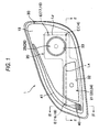
- Fig. 1 is a front view of an automotive headlamp assembly according to a first embodiment of the invention.
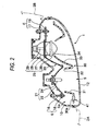
- Fig. 2 is a horizontal sectional view of the headlamp assembly taken along the line II-II of Fig. 1 .
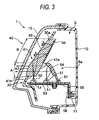
- Fig. 3 is a vertical sectional view of the headlamp assembly taken along the line III-III of Fig. 1 .
- Fig. 4 is a front perspective view of an extension and a light guide member.
- Fig. 5 is a longitudinal sectional view of the light guide member taken along plane parallel to a direction in which the light guide member extends.
- Fig. 6 is a sectional view of the light guide member taken along the line IV-IV of Fig. 4 , illustrating how the light guide member is fixed to the extension.
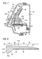
- Fig. 7 is a vertical sectional view of an automotive headlamp assembly according to a second embodiment of the invention.
- Fig. 8 is a longitudinal sectional view of a light guide member of Fig. 7 .
- Fig. 9 is a vertical sectional view of an automotive headlamp assembly according to a third embodiment of the invention.
- Fig. 10 is a longitudinal sectional view of a light guide member of Fig. 9 .
- Fig. 11 is a vertical sectional view of an automotive headlamp assembly according to a fourth embodiment of the invention.
- Fig. 12 is a longitudinal sectional view of a light guide member of Fig. 11 .
- Fig. 13 is a front view of an automotive indicating lamp assembly according to a fifth embodiment of the invention.
- Fig. 14 is a horizontal sectional view of the indicating lamp assembly taken along the line XIV-XIV of Fig. 13 .
- Figs. 1 to 6 illustrate an automotive headlamp assembly according to a first embodiment of the invention.
- the automotive headlamp assembly 1 has a lamp body 10 and a transparent front cover 12 which together form a lamp chamber S.
- a front opening of the lamp body 10 and the front cover 12 extend from a front end portion 2A of a vehicle body and curve toward a side portion 2B of the vehicle body. That is, the front opening of the lamp body 10 and the front cover 12 are rearwardly inclined in a horizontal section, whereby the lamp chamber S is also curved from the front to the side of the vehicle body.
- interior components which can be visually seen through the front cover 12 from the front are illustrated in solid lines.
- the headlamp assembly includes a headlamp section 20 and a clearance section 40 which are both accommodated inside the lamp chamber S.
- the headlamp section 20 is tiltable in vertical and horizontal directions through an aiming mechanism E.
- the headlamp section 20 includes a reflector-type light source unit 21 and a projector-type light source unit 25, which are connected together.
- the reflector-type light source unit 21 is arranged on an inner side of the projector-type light source unit 25 with respect to a widthwise direction of the vehicle body.
- the reflector-type light source unit 21 has a reflector 22 formed with an attaching hole, and a halogen bulb 24 inserted into the attaching hole.
- the reflector-type light source unit 21 is configured to irradiate an upper beam (i.e., a driving beam).
- the projector-type light source unit 25 has a projection lens 26, a cut-off line forming shade 27, an elliptical reflector 28, and a halogen bulb 29.
- the projector-type light source unit 25 is configured to irradiate a lower beam (i.e., a passing beam).
- the aiming mechanism E includes a pair aiming screws 16, 17 which penetrate through the lamp body 10 and forwardly protrudes therefrom, a pair of aiming nuts 18, 19 into which the corresponding aiming screws 16, 17 are respectively inserted, and a ball joint 14 which is disposed between the lamp body 10 and the headlamp section 20 right below the aiming nut 19.
- the aiming nuts 18, 19 are attached to lateral edge portions of the headlamp section 20 respectively.
- the aiming screw 16 serves as a horizontal aiming screw which tilts the headlamp section 20 (i.e., tilts optical axes of the reflector-type light source unit 21 and the projector-type light source unit 25) around a vertical tilting axis Ly which passes through the ball joint 14 and the aiming nut 19.
- the aiming screw 17 serves a vertical aiming screw which tilts the headlamp section 20 (i.e., the optical axes of the reflector-type light source unit 21 and the projector-type light source unit 25) around a horizontal tilting axis Lx which passes through the ball joint 14 and the aiming nut 18.
- An extension 30 is arranged on a front side of the headlamp section 20 inside the lamp chamber S in order to cover a space between the lamp body 10 and the reflector-type light source unit 21 and a space between the lamp body 10 the projector-type light source unit 25.
- a surface of the extension 30 is treated with an aluminum deposition.
- an outer shape of the extension 30 follows the front opening of the lamp body 10, and is positioned inside the lamp chamber S, for example, by being held between the lamp body 10 and the front cover 12.
- the extension 30 has a rectangular cylindrical portion 31 and a circular cylindrical portion 33 which are rearwardly extended.
- a rear end portion of the rectangular cylindrical portion 31 is formed with a rectangular opening 32 corresponding to the reflector 22 of the reflector-type light source unit 21, and a rear end portion of the circular cylindrical portion 33 is formed with a circular opening 34 corresponding to the projection lens 26 of the projector-type light source unit 25.
- the extension 30 is formed with an opening 30a extending, in a strip shape, from an inner side edge portion to a middle of an upper side edge portion of the extension 30.
- the clearance lamp section 40 has a light guide member 41 which is integrally attached into the opening 30a.
- the light guide member 41 is made of transparent synthetic resin, and is formed into a strip shape corresponding to the opening 30a.
- the light guide member 41 is configured such that, from a base end portion, which is the lowermost portion toward a tip end portion which is on an opposite side of the base end portion, in an extending direction of the light guide member 20, a width of the light guide member 20 gradually becomes narrower and a thickness of the light guide member 20 gradually becomes thinner.
- pairs of right and left brackets 42 each formed with a circular hole 42a, are protruded from two locations in a longitudinal direction of the light guide member 41.
- the opening 30a of the extension 30 is formed in such a size that the light guide member 41 is engageable therein, and mounting bases 36 are provided on a rear surface of the extension 30 near a circumferential edge of the opening 30a.
- Each of the mounting bases has a boss 36a configured to be engageable into the corresponding one of the circular holes 42a of the brackets 42 of the light guide member 41. As shown in Fig.
- the light guide member 41 is fitted into the opening 30a from a rear side of the extension 30 such that the circular holes 42a of the brackets 42 engage with the respective bosses 36a of the mounting bases 36, whereby the four brackets 42 contact against the respective mounting bases 36 and a front surface of the extension 30 around the opening 30a and a front surface of the light guide member 41 become substantially flush with each other. Thereafter, each of the bosses 36a is welded to the corresponding bracket 42 by thermal caulking, whereby the light guide member 41 and the extension 30 are integrally fixed together.
- a front surface of the light guide member 41 is formed in an arcuate shape when seen in a cross section (see Fig. 6 ) along the entire length in the longitudinal direction thereof.
- a portion of the front surface of the light guide member 41 i.e., a diffusing front surface of the light guide member 41
- cylindrical steps 43 which vertically diffuse light emitting therefrom.
- the light diffused by cylindrical steps 43 is originally emitted from a first LED 51, and enters into the light guide member 41 from a rear surface of the base end portion of the light guide member 41 (i. e., a first light entering surface 41a of the light guide member 41 ).
- the remaining portion 45 of the front surface of the light guide member 41, where the cylindrical steps 43 are not formed, is textured to have fine surface roughness.
- a portion of the rear surface of the light guide member 21 (an internally reflecting rear surface of the light guide member 41), which is on a rear side of the textured surface 45, is formed with densely stippled dots 46 which reflect light toward the textured surface 45.
- the light reflected by the stippled dots 46 is originally emitted from a second LED 52, and enters into the light guide member 21 from a base end face of the light guide member 41 (a second light entering surface 41b of the light guide member 41).
- the light guide member 41 includes a functional portion A having the diffusing front surface formed with the cylindrical steps 43 from which the light emitted from the first LED 51 and entered into the first light entering surface 41 a is diffusely emitted to provide a clearance lamp light distribution, and a decorative portion B having the internally reflecting rear surface formed with the stippled dots 46 which reflect the light emitted from the second LED 52 and entered into the second light entering surface 41b.
- the light reflected by the internally reflecting rear surface is uniformly emitted from the textured surface 45 on the front side thereof
- a light emitting area of the decorative portion B is larger than a light emitting area of the functional portion A.
- This light guide member 41 is attached to the extension 30, and is disposed inside the lamp chamber S to extend in a strip shape along a circumferential edge of the lamp chamber S and along the front cover 12.
- a parabolic reflector 54 (an optical component) is disposed on a rear side of the functional portion A of the light guide member 41.
- the reflector 54 guides the light from the first LED 51 toward the diffusing front surface (i.e., toward the cylindrical steps 43) of the functional portion A.
- the first LED 51 is disposed right below the reflector 54 at a focal point of the parabolic shape of the reflector 54.
- the first LED 51 is oriented upward such that its light emitting axis L1 extends upward in a direction along which the light guide member 41 extends.
- the light emitting axis L1 of the first LED 51 is directed in an upward direction perpendicular to a front-and-rear direction of the headlamp assembly 1, i.e., perpendicular to optical axes of the reflector-type light source unit 21 and the projector-type light source unit 25.
- the light emitted from the first LED 51 is reflected by the reflector 54 to be substantially parallel light rays, i.e., collimated, and then enters into the light guide member 41 from the first light entering surface 41a, which is a portion of the rear surface of the light guide member 41.
- the light entering from the first light entering surface 41a is then emitted from the diffusing front surface (i.e., from the cylindrical steps 43) to be vertically and horizontally diffused light, whereby a light distribution of the clearance lamp section 40 is provided.
- the second LED 52 is provided as a light source for illuminating the decorative portion B, and is disposed facing against the base end face (i.e., the second light entering surface 41b) of the light guide member 41.
- the second LED 52 is also oriented upward such that its light emitting axis L2 is directed in the upward direction perpendicular to the front-and-rear direction of the headlamp assembly 1, i.e., perpendicular to the second light entering surface 41 b.
- the light emitting axis L2 of the second LED 52 is set to be parallel to the light emitting axis L1 of the first LED 51.
- the light emitted from the second LED 52 enters from the base end face (i.e., the second light entering surface 41b) of the light guide member 41, and is reflected by the stippled dots 46 on the rear surface of the light guide member 41 after being internally reflected inside the light guide member 41.
- the light reflected by the stippled dots 46 is then emitted from the textured surface 45 on the front of the light guide member 41 such that the light is diffused in various directions, whereby the entire decorative portion B is uniformly illuminated with relatively less light intensity.
- the first LED 51 and the second LED 52 are mounted on a single flat circuit board 53 so as to be adjacent to each other in the front-and-rear direction.
- the circuit board 53 is fixed to an L-shaped metallic (for example, aluminum) bracket 56, which has good heat conductance, with a screw 57.
- the bracket 56, with respect to which the LEDs 51, 52 are fixed, and the reflector 54 are fixed together to a boss 11, which inwardly protrudes from an inner surface of a back wall of the lamp body 10, with a screw 58.
- the headlamp assembly 1 according to the first embodiment has one or more of the following advantages.
- the light guide member 41 i.e., the functional portion A and the decorative portion B which extends along the circumferential edge of the lamp chamber S and along the front cover 12 in the strip shape
- a light emitting rear in the widthwise direction of the light guide member 41 is narrower than the related art light guide member. Therefore, the two LEDs 51, 52 are sufficient to provide the light source for the clearance lamp section 40. Accordingly, cost of the headlamp assembly 1 can be reduced.
- the long light emitting surface of the strip-shaped light guide member 41 i.e., the functional portion A and the decorative portion B
- the front cover 12 Second, improved visibility of the clearance lamp section 40 can be achieved with only two LEDs 51, 52.
- the decorative portion B is illuminated by the light emitted from the second LED 52 and entered into the light guide member 41 from the base end face (the second light entering surface 41b).
- the intensity of light guided inside the light guide member 41 tends to decrease as its optical path becomes longer toward the tip end side of the light guide member 41. Therefore, the light guide member 41 of the embodiment is configured such that the width and the thickness thereof becomes gradually smaller from the base end side, from which the light from the second LED 52 enters, toward the tip end side which is opposite to the base end side in the extending direction of the light guide member 41 in order to gradually reduce energy loss of the light guiding toward the tip end side of the light guide member 41. That is, the decorative portion B is configured to emit light with substantially equal brightness from the base end side to the tip end side to improve visibility of the clearance lamp section 40.
- the light guide member 41 of the clearance lamp section 40 is attached to the extension 30 and is positioned closer to the front cover 12 than the reflector-type light source unit 21 for the upper beam and the projector-type light source unit 25 for the lower beam, which are disposed deeper inside the lamp chamber S. Therefore, the light emission from the clearance lamp section 40 (i.e., from the light guide member 41) can be clearly seen from oncoming vehicles and the pedestrians through the front cover 12.
- the upper beam and the lower beam are irradiated from the deeper positions than the clearance lamp section 40 (the light guide member 41) which emits light along the circumferential edge of the lamp chamber S near the front cover 12. Therefore, when the headlamp section 20 is turned on, a sedate, unique, and dignified, high-quality appearance is provided due to the depth effect created inside the lamp chamber S.
- the first and second LEDs 51, 52 are disposed such that the respective light emitting axes L1, L2 are directed in the direction along which the light guide member 41 extends. Therefore, the components of the clearance lamp section 40, i.e., the light guide member 41 and the first and second LEDs 51, 52 are disposed near the circumferential edge of the lamp chamber S and along the front cover 12, without requiring much accommodating space in the front-and-rear direction. Accordingly, the clearance lamp section 40 can be incorporated even inside the lamp chamber S having a relatively small depth.
- a space Sa is provided between the light guide member 41, which is integrally attached into the circumferential edge portion of the extension 30 and extends obliquely rearward along the front cover 12, and the reflector 22 of the headlamp section 20, which is vertically arranged on the rear side of the light guide member 41.
- the space Sa becomes wider in the front-and-rear direction towards the base end side of the light guide member 41.
- the first LED 51 and the reflector 54 of the clearance lamp section 40 are disposed in this space Sa, whereby the first LED 51 and the reflector 54 is prevented from interfering with the headlamp section 20 which is vertically and horizontally tiltable. That is, the space Sa behind the light guide member 41 is effectively used as the accommodating space for the first LED 51 and the reflector 54 to reduce size of the lamp body 10, which leads to a reduction in size of the entire headlamp assembly 1.
- the first LED 51 and the second LED 52 are disposed such that the respective light emitting axes L1, L2 thereof are parallel to each other and such that the first LED 51 and the second LED 52 are disposed adjacent to each other in the front-and-rear direction. Therefore, only one reference surface is required on the bracket 56 for mounting the LEDs 51, 52. In addition, the first LED 51 and the second LED 52 are mounted on the single circuit board 53. Therefore, the number of components of the clearance lamp section 40 can be reduced, and the assembling of the components into the lamp body 10 is simplified.
- Figs. 7 and 8 illustrate an automotive headlamp assembly according to a second embodiment of the invention.
- the parabolic reflector 54 which is an optical component for guiding the light from the first LED 51 to the diffusing front surface (i.e., to the cylindrical steps 43), is provided as a separate component from the light guide member 41 and is disposed on the rear side of the light guide member 41.
- an internally reflecting face 54A having a parabolic shape is integrally formed on a rear portion of a light guide member 41A to guide a light from the first LED 51 to a diffusing front surface (i.e., to cylindrical steps 43).
- a bulged portion 44 having a parabolic outer circumferential surface is integrally formed on the rear portion of the light guide member 41A at a portion corresponding to the diffusing front surface having the cylindrical steps 43, i.e., the bulged portion 44 and the light guide member 41A are formed in a one-piece structure, and the internally reflecting face 54A is provided on the outer circumferential surface of the bulged portion 44 by aluminum deposition.
- a lower end face of the bulged portion 44 is formed to be flush with a base end face 41b of the light guide member 41A (i.e., a second light entering surface 41b).
- the lower end face of the bulged portion 44 facing against the first LED 51 serves as a first light entering surface 41 c, from which the light from the first LED 51 enters.
- the first LED 51 is disposed at a focal point of the parabolic shape of the internally reflecting face 54A.
- the number of components of the clearance lamp section 40A is less than that in the first embodiment because the internally reflecting face 54A (i.e., the optical component) and the light guide member 41A are formed in a one-piece structure. Therefore, it is not necessary to consider the optical arrangement between the reflector 54, the light guide member 41 and the first LED 51 during the assembling work as in the first embodiment.
- the configuration of the clearance lamp section 40A of the second embodiment is more simple than that of the first embodiment, and the assembling work of the components of the clearance lamp section 40 into the lamp body 10 is facilitated.
- Figs. 9 and 10 illustrate an automotive headlamp assembly according to a third embodiment of the invention
- Figs. 11 and 12 illustrate an automotive headlamp assembly according to a fourth embodiment of the invention.
- the functional portion A is provided to include the base end face of the light guide member 41 (41A) of the clearance lamp section 40 (40A).
- a functional portion A is provided in a position which is spaced away in a longitudinal direction from a base end face of a light guide member 41B (41C) of a clearance lamp section 40B (40C), and a decorative portion B is divided into two parts on respective sides of the functional portion A in the longitudinal direction of the light guide member 41B (41 C).
- the reflector 54 is disposed on a rear side of the light guide member 41B to guide a light from the first LED 51 to a diffusing front surface having cylindrical steps 43 on a front portion of the light guide member 41B.
- the first LED 51 is disposed at a focal point of the parabolic shape of the reflector 54, and the light emitted from the first LED is reflected by the reflector 54 to enter a first light entering surface 41 a which is on a rear side of the cylindrical steps 43.
- a parabolic internally reflecting face 54A is integrally formed on a bulged portion 44 on a rear side of the light guide member 41 C to guide a light from a first LED 51 to a diffusing front surface having cylindrical steps 43.
- the first LED 51 is disposed at a focal point of the parabolic shape of the internally reflecting face 54A, and the light emitted from the first LED 51 enters a first light entering surface 41c which is a lower end face of the bulged portion 44.
- the first light entering surface 41 c is parallel to a base end face (a second light entering surface41b) of the light guide member 41C.
- the first LED 51 and the second LED 52 are mounted on a single flexible circuit board 53A, and the circuit board 53A is fixed to a metallic (for example, aluminum) bracket 56A, which is bent in a stepped shape, with screws 57a, 57b.
- the bracket 56A with respect to which the LEDs 51, 52 fixed (together with the reflector 54 in the third embodiment), is fixed to a boss 11, which is inwardly protruded from an inner surface of a back wall of a lamp body 10, with a screw 58.
- the light guide member 41B, 41C includes the functional portion A in an intermediate portion thereof in the longitudinal direction, and the divided parts of the decorative portions B on respective sides of the functional portion A, interposing the functional portion A between the divided parts of the decorative portions B. Therefore, a unique illumination of the clearance lamp section 40B, 40C can be obtained.
- Figs. 13 and 14 illustrate an automotive stop lamp assembly according to a fifth embodiment of the invention.
- the stop lamp assembly 2 includes a lamp body 110, a front cover 112 which forms a lamp chamber S1 together with the lamp body 110 and transmits red light, a stop lamp section 20A, a tail lamp section 40D, and a transparent inner lens 60.
- the stop lamp section 20A and the tail lamp section 40D are accommodated inside the lamp chamber S1.
- the stop lamp section 20A includes a bulb 124 and a reflector 122 which reflects a light emitted from the bulb 124.
- the tail lamp section 40D includes strip-shaped light guide members 41D which are integrally attached to the inner lens 60 and which laterally extend along the front cover 112.
- the inner lens 60 has a rectangular shape when viewed from the front, and supports the light guide members 41D on an inner side of the front cover 112.
- the inner lens is configured to diffuse the light reflected by the reflector 122.
- the inner lens 60 may by attached to the lamp body 110 by being welded to a circumferential portion of a front opening of the lamp body 110.
- the inner lens 60 is formed with three openings 63, which horizontally extend in a strip shape. On a rear surface of the inner lens 60 where the openings 63 are not formed, fish-eye steps are formed to vertically and horizontally diffuse the light reflected by the reflector 122 and transmitted through the inner lens 60.
- each of the openings 63 the corresponding light guide member 41D of the tail lamp section 40D is integrally attached from a rear side.
- Each of the light guide members 41D is fixed to the inner lens 60 in a similar manner as in the first embodiment in which the brackets 42 formed with the circular holes 42a and the mounting bases 36 having the boss 36a are used. That is, the light guide members 41D are fixed to the inner lens 60 using brackets 142, which are provided on opposing sides of the respective light guide members 41D and formed with a circular hole 142 respectively, and mounting bases 136, which are provided on circumferential edge portion of the openings 63 on the rear surface of the inner lens 60 and have a boss respectively.
- Parabolic reflectors 154 (optical components) of the tail lamp section 40D are disposed facing against the corresponding first light entering surface 41 a, and are configured as a reflector unit 153 which is fixed to the lamp body 110 with a screw 58. In the reflector unit 153, the reflectors 154 are arranged to be adjacent to each other in a vertical direction.
- the second red LEDs 52A are disposed facing the second light entering surface 41a of the decorative portion B of the corresponding light guide member 41D, and are mounted on a circuit board 53 such that light emitting axes L2 thereof are parallel to light emitting axes L1 of the first red LEDs 51A.
- the circuit board 53, on which six LEDs 51A, 52A are mounted in total, and the reflector unit 153 are fixed to the lamp body 110 via a metallic bracket 156.
- the light emitting surfaces of the strip-shaped light guide members 41D are directly visible for following drivers and pedestrians through the front cover 112. Therefore, improved visibility of the tail lamp section 40D can be achieved, although the light source for each of the light guide members 41D has only two LEDs 51A, 52A.
- the parabolic reflectors 154 for guiding the light from the first red LEDs 51A toward the light distribution emitting portions are disposed on the rear side of the light guide members 41D as separate components from the light guide members 41D.
- a bulged portion 44 formed with parabolic internally reflecting faces 54A as shown in Figs. 7 and 8 may be provided instead of the reflectors 154.
- the bulged portion 44 and the corresponding one of the light guide members 41D can be formed in a one-piece structure.
- the light from the bulb 124 which is white, is transmitted through the red light transmissive front cover 112.
- a red cap (not shown) may be provided to surround the bulb 112 to obtain a red light emission from the bulb 112 so that the front cover 112 may be a colorless transparent cover.
- a stop lamp assembly is presented as one example of an indicating lamp assembly.
- an indicating lamp assembly to which one or more embodiments of the present invention is applicable may have functions of a turn signal lamp and a clearance lamp by utilizing the bulb 124 and the reflector 122 as components of a turn signal lamp section and by utilizing the light guide members 41D and LEDs 51, 52 as components of a clearance lamp section. Also, in such a case, the two lamp sections are accommodated in the same lamp chamber S1.
- the first LED 51 and the second LED 52 are disposed such that the respective light emitting axes L1, L2 are parallel to each other.
- the first and second LEDs 51, 52 may be arranged such that the light emitting axes L1, L2 are orthogonal to each other.
- the embodiments shown in Figs. 3 and 9 may be modified such that the first LED 51 and the reflector 54 are rotated by 90 degrees around an axis parallel to the front-and-rear direction while maintaining the reflector 54 to face against the first light entering surface 41a.
- the embodiment shown in Fig. 3 may be modified such that the first LED 51 is oriented to face the first light entering surface 41a of the light guide member 41, i.e., such that the light emitting axis L1 of the first LED 51 is forwardly directed.
- a convex lens or a Fresnel lens is disposed between the first LED 51 and the light entering surface 41a, and the first LED 51 is disposed at a focal point of the convex lens or the Fresnel lens.
- the convex lens or the Fresnel lens serves as an optical component which collimates the light from the first LED 51 toward the light entering surface 41 a.
- the convex lens or the Fresnel lens of the modified example described above may be integrally provided on a rear side portion of the functional portion A to be a part of a one-piece structured light guide member 41.
- the convex lens or the Fresnel lens does not need to be provided as a separate component, the configuration of the clearance lamp section is simplified, and the assembling work of components of the clearance lamp section into the lamp body 10 is also simplified.
Landscapes
- Engineering & Computer Science (AREA)
- General Engineering & Computer Science (AREA)
- Mechanical Engineering (AREA)
- Physics & Mathematics (AREA)
- Microelectronics & Electronic Packaging (AREA)
- Optics & Photonics (AREA)
- Non-Portable Lighting Devices Or Systems Thereof (AREA)
- Lighting Device Outwards From Vehicle And Optical Signal (AREA)
Applications Claiming Priority (1)
| Application Number | Priority Date | Filing Date | Title |
|---|---|---|---|
| JP2007322737A JP4979565B2 (ja) | 2007-12-14 | 2007-12-14 | 車両用灯具 |
Publications (3)
| Publication Number | Publication Date |
|---|---|
| EP2071228A2 true EP2071228A2 (fr) | 2009-06-17 |
| EP2071228A3 EP2071228A3 (fr) | 2010-06-02 |
| EP2071228B1 EP2071228B1 (fr) | 2013-10-30 |
Family
ID=40433414
Family Applications (1)
| Application Number | Title | Priority Date | Filing Date |
|---|---|---|---|
| EP08021620.3A Expired - Fee Related EP2071228B1 (fr) | 2007-12-14 | 2008-12-12 | Ensemble de phares de véhicule |
Country Status (5)
| Country | Link |
|---|---|
| US (1) | US7946743B2 (fr) |
| EP (1) | EP2071228B1 (fr) |
| JP (1) | JP4979565B2 (fr) |
| KR (1) | KR101065813B1 (fr) |
| CN (1) | CN101457892B (fr) |
Cited By (35)
| Publication number | Priority date | Publication date | Assignee | Title |
|---|---|---|---|---|
| EP2384934A1 (fr) * | 2010-05-07 | 2011-11-09 | odelo GmbH | Lampe de véhicule automobile avec plusieurs fonctions d'éclairage |
| EP2439132A2 (fr) | 2010-10-11 | 2012-04-11 | Motogadget GmbH | Dispositif d'éclairage pour un véhicule |
| EP2466197A1 (fr) * | 2010-12-20 | 2012-06-20 | odelo GmbH | Lampe de véhicule automobile |
| EP2479487A1 (fr) * | 2011-01-24 | 2012-07-25 | Valeo Vision | Dispositif d'éclairage et/ou de signalisation d'un véhicule automobile et procédé de montage d'un tel dispositif |
| EP2502784A1 (fr) * | 2011-03-24 | 2012-09-26 | Volkswagen Aktiengesellschaft | Lampe de véhicule, en particulier pour éclairer l'intérieur du véhicule |
| EP2530372A1 (fr) * | 2011-05-30 | 2012-12-05 | Odelo GmbH | Guide optique pour éclairage de véhicule automobile |
| FR2977926A1 (fr) * | 2011-06-30 | 2013-01-18 | Valeo Vision | Dispositif optique et systeme de signalisation et/ou eclairage |
| WO2013131114A1 (fr) * | 2012-03-07 | 2013-09-12 | Zizala Lichtsysteme Gmbh | Dispositif d'éclairage pour un véhicule automobile |
| EP2357396A3 (fr) * | 2010-02-08 | 2013-10-16 | Automotive Lighting Reutlingen GmbH | Dispositif d'éclairage de véhicule automobile doté d'une lampe intégrée |
| ITTV20130033A1 (it) * | 2013-03-01 | 2014-09-02 | Automotive Lighting Italia Spa | Fanale automobilistico |
| WO2014199108A1 (fr) * | 2013-06-14 | 2014-12-18 | Automotive Lighting Rear Lamps France | Module d'éclairage pour automobiles à homogénéité de lumière à évolution continue |
| EP2824385A1 (fr) * | 2013-07-09 | 2015-01-14 | Valeo Vision | Dispositif d'éclairage et/ou de signalisation bi-couleur comprenant un guide de lumière, notamment pour véhicule automobile |
| ITPD20130325A1 (it) * | 2013-11-27 | 2015-05-28 | Automotive Lighting Italia Spa | Dispositivo di illuminazione per veicoli |
| EP2639499A3 (fr) * | 2012-03-12 | 2015-08-19 | Zumtobel Lighting GmbH | Module à DEL avec plaque guide de lumière |
| WO2015135962A1 (fr) * | 2014-03-12 | 2015-09-17 | Volkswagen Aktiengesellschaft | Véhicule automobile et phare de véhicule automobile comprenant un boîtier d'adaptateur |
| EP2990720A1 (fr) * | 2014-08-25 | 2016-03-02 | Stanley Electric Co., Ltd. | Unité d'éclairage de véhicule |
| AT516170B1 (de) * | 2014-09-16 | 2016-03-15 | Zizala Lichtsysteme Gmbh | Beleuchtungsvorrichtung mit darin verriegelbarer lichtleiteranordnung |
| EP2338732B1 (fr) * | 2009-12-16 | 2016-08-17 | Automotive Lighting Reutlingen GmbH | Dispositif d'éclairage de véhicule automobile doté d'un guide de lumière et de sources lumineuses de différentes couleurs |
| EP3073183A1 (fr) * | 2015-03-25 | 2016-09-28 | Automotive Lighting Italia S.p.A. | Dispositif d'éclairage pour véhicules |
| EP3098499A1 (fr) * | 2015-05-27 | 2016-11-30 | Peugeot Citroën Automobiles SA | Bloc optique de véhicule à plaque de support de sources de lumière partagée pour le placement d'une fonction photométrique dans une autre fonction photométrique |
| CN103574464B (zh) * | 2012-08-03 | 2017-04-12 | 汽车照明罗伊特林根有限公司 | 用于光模块的初级光学单元 |
| EP2562045A3 (fr) * | 2011-08-25 | 2017-09-13 | Stanley Electric Co., Ltd. | Dispositif d'éclairage de véhicule |
| ITUA20162153A1 (it) * | 2016-03-31 | 2017-10-01 | Automotive Lighting Italia Spa | Fanale automobilistico |
| US9810393B2 (en) | 2015-08-31 | 2017-11-07 | Varroc Lighting Systems, s.r.o. | Motor vehicle light device including light guide and flat electroluminsscence diode |
| EP2693105A3 (fr) * | 2012-07-31 | 2018-03-14 | Stanley Electric Co., Ltd. | Dispositif d'éclairage de véhicule |
| EP2447601A3 (fr) * | 2010-10-28 | 2018-04-18 | Koito Manufacturing Co., Ltd. | Lampe de véhicule |
| CN108613125A (zh) * | 2016-12-23 | 2018-10-02 | 市光法雷奥(佛山)汽车照明系统有限公司 | 用于机动车辆的发光装置 |
| EP3418626A4 (fr) * | 2016-02-15 | 2018-12-26 | LG Innotek Co., Ltd. | Lampe et véhicule équipé de cette dernière |
| EP3434518A3 (fr) * | 2014-03-03 | 2019-03-06 | Koito Manufacturing Co., Ltd. | Phare de véhicule et système de commande de phare de véhicule |
| ES2748207A1 (es) * | 2018-09-13 | 2020-03-13 | Seat Sa | Faro para vehiculo automovil |
| CN113531478A (zh) * | 2021-07-19 | 2021-10-22 | 东风汽车集团股份有限公司 | 一种隐藏式车灯光学结构及其车灯 |
| FR3120930A1 (fr) * | 2021-03-16 | 2022-09-23 | Psa Automobiles Sa | Bloc optique compact et assurant des fonctions photométriques d’éclairage et de signalisation, pour un véhicule |
| US11603976B2 (en) | 2021-02-08 | 2023-03-14 | Volkswagen Aktiengesellschaft | Motor vehicle headlamp and method for operating a motor vehicle headlamp |
| WO2023117810A1 (fr) * | 2021-12-23 | 2023-06-29 | Valeo Vision | Ensemble optique pour véhicule automobile, dispositif d'éclairage et/ou d'indication de signalisation, et véhicule automobile |
| FR3141751A1 (fr) * | 2022-11-03 | 2024-05-10 | Psa Automobiles Sa | Bloc optique à module optique préassemblé et rapporté, pour un véhicule |
Families Citing this family (104)
| Publication number | Priority date | Publication date | Assignee | Title |
|---|---|---|---|---|
| JP5359654B2 (ja) * | 2009-07-30 | 2013-12-04 | 市光工業株式会社 | 車両用灯具 |
| JP5363235B2 (ja) * | 2009-08-04 | 2013-12-11 | 株式会社小糸製作所 | 車両用灯具 |
| JP5469965B2 (ja) * | 2009-09-04 | 2014-04-16 | 株式会社小糸製作所 | サイドターンシグナルランプ |
| JP5457780B2 (ja) * | 2009-10-14 | 2014-04-02 | 株式会社小糸製作所 | 車輌用灯具 |
| DE102010006974A1 (de) * | 2010-02-05 | 2011-08-11 | GM Global Technology Operations LLC, ( n. d. Ges. d. Staates Delaware ), Mich. | Beleuchtungseinrichtung für ein Fahrzeug |
| DE202010003058U1 (de) * | 2010-03-03 | 2010-05-20 | Automotive Lighting Reutlingen Gmbh | Kraftfahrzeugscheinwerfer mit einer Lichtquelle und wenigstens zwei Licht verteilenden optischen Elementen |
| JP5523873B2 (ja) * | 2010-03-03 | 2014-06-18 | スタンレー電気株式会社 | 車両用前照灯 |
| US9134474B2 (en) * | 2010-03-16 | 2015-09-15 | Toyota Motor Engineering & Manufacturing North America, Inc. | Headlamp bulb type light pipe |
| JP5529602B2 (ja) * | 2010-03-18 | 2014-06-25 | 株式会社小糸製作所 | 車両用灯具 |
| JP2011238582A (ja) * | 2010-04-12 | 2011-11-24 | Koito Mfg Co Ltd | 車輌用灯具 |
| JP5562120B2 (ja) * | 2010-05-21 | 2014-07-30 | スタンレー電気株式会社 | 車両用灯具ユニット |
| KR101241678B1 (ko) | 2010-06-30 | 2013-03-11 | 현대자동차주식회사 | 차량용 리어램프 |
| WO2012011947A1 (fr) * | 2010-07-20 | 2012-01-26 | Magna International Inc. | Phare de croisement à diodes électroluminescentes à projecteur hybride |
| JP5721367B2 (ja) * | 2010-08-24 | 2015-05-20 | 株式会社小糸製作所 | 車両用灯具 |
| DE102010061210A1 (de) * | 2010-12-14 | 2012-06-14 | Hella Kgaa Hueck & Co. | Leuchte für Fahrzeuge |
| AT510931B1 (de) * | 2010-12-22 | 2013-09-15 | Zizala Lichtsysteme Gmbh | Fahrzeugscheinwerfer mit led-lichtmodul |
| JP5651025B2 (ja) * | 2011-01-20 | 2015-01-07 | 本田技研工業株式会社 | ヘッドライト |
| JP5708991B2 (ja) * | 2011-03-30 | 2015-04-30 | スタンレー電気株式会社 | 車両用灯具及び車両用灯具に用いられる導光レンズ |
| KR101235317B1 (ko) * | 2011-05-13 | 2013-02-20 | 에스엘 주식회사 | 차량용 램프 |
| JP5773189B2 (ja) * | 2011-05-23 | 2015-09-02 | スタンレー電気株式会社 | 灯具 |
| WO2013003366A1 (fr) * | 2011-06-30 | 2013-01-03 | Hella Corporate Center Usa, Inc. | Appareil et procédé pour marqueur latéral à lame de lumière |
| JP5773795B2 (ja) * | 2011-08-08 | 2015-09-02 | 株式会社小糸製作所 | 灯具 |
| JP5906050B2 (ja) | 2011-09-30 | 2016-04-20 | 株式会社小糸製作所 | 車両用灯具 |
| KR101382456B1 (ko) * | 2011-10-12 | 2014-04-08 | 현대모비스 주식회사 | 차량용 램프 장치. |
| DE102011119231A1 (de) * | 2011-11-23 | 2013-05-23 | Audi Ag | Kraftfahrzeugleuchte, Kraftwagen und Verfahren zum Betreiben einer Kraftfahrzeugleuchte |
| FR2983279B1 (fr) * | 2011-11-24 | 2015-08-21 | Valeo Vision | Element opaque et mobile empechant une focalisation des rayons solaires dans un projecteur |
| JP5903279B2 (ja) * | 2012-01-19 | 2016-04-13 | 株式会社小糸製作所 | 車両用灯具 |
| JP5945857B2 (ja) * | 2012-01-24 | 2016-07-05 | スタンレー電気株式会社 | 車両用前照灯及び導光レンズ |
| JP2013171795A (ja) * | 2012-02-22 | 2013-09-02 | Stanley Electric Co Ltd | 車両用灯具 |
| JP6029298B2 (ja) | 2012-03-14 | 2016-11-24 | 株式会社小糸製作所 | 車両用灯具 |
| JP2013222553A (ja) * | 2012-04-13 | 2013-10-28 | Koito Mfg Co Ltd | 車両用灯具 |
| US8820992B2 (en) * | 2012-05-23 | 2014-09-02 | Ford Global Technologies, Llc | Automotive headlamp assembly |
| JP2014007049A (ja) * | 2012-06-25 | 2014-01-16 | Koito Mfg Co Ltd | 光学系ユニットおよび車両用灯具 |
| JP5717694B2 (ja) * | 2012-06-26 | 2015-05-13 | トヨタ自動車東日本株式会社 | 車両用のランプ装置 |
| JP5941383B2 (ja) * | 2012-09-19 | 2016-06-29 | 株式会社小糸製作所 | 車両用灯具 |
| DE102012109422B4 (de) | 2012-10-04 | 2023-07-06 | HELLA GmbH & Co. KGaA | Verfahren zur Anordnung eines Lichtleitstabes in einer Beleuchtungseinrichtung eines Fahrzeugs |
| DE102012112072B4 (de) * | 2012-12-11 | 2022-09-01 | HELLA GmbH & Co. KGaA | Beleuchtungsvorrichtung für Fahrzeuge |
| JP6280689B2 (ja) * | 2012-12-13 | 2018-02-14 | 株式会社小糸製作所 | 反射膜を備えた車両用灯具 |
| JP6199032B2 (ja) * | 2012-12-26 | 2017-09-20 | 株式会社小糸製作所 | 車両用灯具 |
| JP2014127412A (ja) * | 2012-12-27 | 2014-07-07 | Ichikoh Ind Ltd | 車両用灯具 |
| CN103104883B (zh) * | 2013-01-22 | 2015-04-08 | 东莞明新塑胶制品有限公司 | 导光透镜及led灯 |
| EP2770127B1 (fr) * | 2013-02-22 | 2019-01-02 | Geberit International AG | Dispositif de montage pour un corps sanitaire |
| JP6048749B2 (ja) * | 2013-04-24 | 2016-12-21 | 本田技研工業株式会社 | 車両用灯火装置 |
| DE102013104590A1 (de) * | 2013-05-06 | 2014-11-06 | Hella Kgaa Hueck & Co. | Beleuchtungsvorrichtung für Fahrzeuge |
| CN104235721B (zh) * | 2013-06-20 | 2017-12-26 | 汽车照明罗伊特林根有限公司 | 机动车的照明装置 |
| FR3007821B1 (fr) * | 2013-06-28 | 2018-04-20 | Automotive Lighting Rear Lamps France | Dispositif a eclairage indirect pour feu arriere de vehicule automobile |
| JP6399504B2 (ja) * | 2013-07-02 | 2018-10-03 | 東洋工業塗料株式会社 | 金属蒸着膜上塗布用の(ツヤ有り)蓄光塗料を用いた車両用灯具部品 |
| KR101997062B1 (ko) | 2013-08-08 | 2019-10-01 | 에스엘 주식회사 | 엘이디 램프 어셈블리 |
| KR101592648B1 (ko) | 2013-12-23 | 2016-02-12 | 현대자동차주식회사 | 헤드램프 장치 |
| FR3017189B1 (fr) | 2014-02-04 | 2019-04-26 | Valeo Vision | Module d'eclairage et/ou de signalisation rotatif a source lumineuse fixe |
| JP2015195086A (ja) * | 2014-03-31 | 2015-11-05 | 株式会社小糸製作所 | 導光体を備えた光ガイド装置 |
| JP6361248B2 (ja) * | 2014-04-09 | 2018-07-25 | 市光工業株式会社 | 車両用灯具 |
| JP6347140B2 (ja) * | 2014-04-15 | 2018-06-27 | 市光工業株式会社 | 車両用灯具 |
| JP5786068B2 (ja) * | 2014-06-10 | 2015-09-30 | スタンレー電気株式会社 | 車両用灯具ユニット |
| KR102243936B1 (ko) * | 2014-07-04 | 2021-04-23 | 에스엘 주식회사 | 차량용 램프의 렌즈 및 이를 이용한 차량용 램프 |
| KR200481201Y1 (ko) | 2014-07-16 | 2016-08-31 | 에스엘 주식회사 | 차량용 램프 어셈블리 |
| DE102014110399A1 (de) * | 2014-07-23 | 2016-01-28 | Dr. Ing. H.C. F. Porsche Aktiengesellschaft | Beleuchtungseinrichtung |
| CN106574759B (zh) * | 2014-09-30 | 2019-05-28 | 麦克赛尔株式会社 | 车辆用灯具 |
| CN105584566B (zh) * | 2014-10-24 | 2021-09-24 | 雅马哈发动机株式会社 | 速克达型车辆 |
| DE102014116517B4 (de) * | 2014-11-12 | 2022-04-28 | Dr. Ing. H.C. F. Porsche Aktiengesellschaft | Beleuchtungseinrichtung |
| JP6457793B2 (ja) | 2014-11-20 | 2019-01-23 | 株式会社小糸製作所 | 標識灯 |
| KR101684004B1 (ko) * | 2014-11-25 | 2016-12-08 | 현대자동차주식회사 | 차량용 램프의 광원모듈 |
| JP6413717B2 (ja) * | 2014-12-05 | 2018-10-31 | 市光工業株式会社 | 車両用灯具 |
| JP2016134324A (ja) * | 2015-01-21 | 2016-07-25 | スタンレー電気株式会社 | 車両用灯具 |
| FR3032926B1 (fr) * | 2015-02-19 | 2018-08-17 | Valeo Vision | Dispositif d'eclairage de vehicule automobile |
| JP6514912B2 (ja) * | 2015-02-26 | 2019-05-15 | 株式会社村上開明堂 | ターンランプ |
| JP6456198B2 (ja) * | 2015-03-11 | 2019-01-23 | スタンレー電気株式会社 | 車両用灯具における部品の位置決め構造 |
| JP6560514B2 (ja) * | 2015-03-20 | 2019-08-14 | 株式会社小糸製作所 | 車両用灯具 |
| US9677731B2 (en) * | 2015-04-30 | 2017-06-13 | Osram Sylvania Inc. | Motor vehicle accent lamp and methods of use thereof |
| CN105135316B (zh) * | 2015-08-25 | 2018-06-29 | 马瑞利汽车零部件(芜湖)有限公司 | 一种复合光学系统的汽车尾灯 |
| DE102015216744A1 (de) * | 2015-09-02 | 2017-03-02 | Volkswagen Aktiengesellschaft | Fahrzeugleuchte und Verfahren zum Bereitstellen einer Lichtfunktion mittels einer Fahrzeugleuchte |
| JP6716259B2 (ja) * | 2016-01-14 | 2020-07-01 | スタンレー電気株式会社 | 車両用灯具 |
| JP6725281B2 (ja) * | 2016-03-24 | 2020-07-15 | スタンレー電気株式会社 | 車両用灯具 |
| JP6357507B2 (ja) * | 2016-07-04 | 2018-07-11 | 日本精機株式会社 | 車両用表示装置 |
| CZ2016481A3 (cs) * | 2016-08-08 | 2018-02-21 | Varroc Lighting Systems, s.r.o. | Světelné zařízení pro motorová vozidla |
| AT518552B1 (de) * | 2016-08-19 | 2017-11-15 | Zkw Group Gmbh | Beleuchtungseinheit für einen Kraftfahrzeugscheinwerfer zum Erzeugen von zumindest zwei Lichtverteilungen |
| JP6744196B2 (ja) * | 2016-10-31 | 2020-08-19 | スタンレー電気株式会社 | 車両用灯具 |
| US10845528B2 (en) | 2016-11-04 | 2020-11-24 | Lg Innotek Co., Ltd. | Lighting device |
| JP6742228B2 (ja) * | 2016-12-01 | 2020-08-19 | 株式会社小糸製作所 | 灯具 |
| US10730430B2 (en) * | 2017-01-06 | 2020-08-04 | Ford Global Technologies, Llc | Sidemarker light assembly and motor vehicle light assembly incorporating that sidemarker light assembly |
| US10619817B2 (en) * | 2017-01-24 | 2020-04-14 | Valeo North America, Inc. | Vehicle light assembly having a reflex lens with a locking detent |
| ES2693586B2 (es) * | 2017-06-08 | 2020-06-16 | Seat Sa | Dispositivo de iluminación para un vehículo, y portón trasero asociado. |
| KR101982779B1 (ko) * | 2017-06-21 | 2019-05-27 | 엘지전자 주식회사 | 차량용 램프 및 차량 |
| JP2019038315A (ja) * | 2017-08-23 | 2019-03-14 | サカエ理研工業株式会社 | 車両用装飾部品 |
| KR102439106B1 (ko) * | 2017-09-05 | 2022-09-05 | 현대자동차주식회사 | 차량의 리어 램프 장치 |
| WO2019069682A1 (fr) * | 2017-10-06 | 2019-04-11 | 株式会社小糸製作所 | Phare de véhicule |
| US10151436B1 (en) * | 2017-10-12 | 2018-12-11 | GM Global Technology Operations LLC | Vehicle lighting assembly with light transfer optical system |
| KR102435180B1 (ko) * | 2017-11-29 | 2022-08-23 | 에스엘 주식회사 | 차량용 램프 |
| KR101987295B1 (ko) * | 2017-12-28 | 2019-06-11 | 에스엘 주식회사 | 차량용 램프 |
| CZ309102B6 (cs) * | 2018-02-23 | 2022-02-02 | Varroc Lighting Systems, s.r.o. | Světelné zařízení s vícenásobnou světelnou funkcí |
| JP6855404B2 (ja) * | 2018-03-16 | 2021-04-07 | 株式会社豊田自動織機 | 車両用灯具 |
| JP2020004483A (ja) * | 2018-06-25 | 2020-01-09 | 株式会社小糸製作所 | 車両用灯具 |
| JP7075842B2 (ja) * | 2018-07-20 | 2022-05-26 | スタンレー電気株式会社 | 車両用灯具 |
| CN209371135U (zh) * | 2019-01-14 | 2019-09-10 | 法雷奥照明湖北技术中心有限公司 | 光学组件、车辆用灯具和车辆 |
| GB2585687B (en) | 2019-07-11 | 2021-08-18 | Dyson Technology Ltd | Vehicle lamps |
| US10895361B1 (en) * | 2019-08-22 | 2021-01-19 | Valeo North America, Inc. | Optical device for an automobile vehicle |
| JP2021154948A (ja) * | 2020-03-27 | 2021-10-07 | 本田技研工業株式会社 | 車両における報知装置 |
| CN214038235U (zh) * | 2020-11-27 | 2021-08-24 | 华域视觉科技(上海)有限公司 | 远光光学元件、远光照明单元和车辆 |
| DE102020131702A1 (de) * | 2020-11-30 | 2022-06-02 | HELLA GmbH & Co. KGaA | Beleuchtungsvorrichtung für ein Kraftfahrzeug |
| JP7217301B2 (ja) * | 2021-02-18 | 2023-02-02 | 本田技研工業株式会社 | 車両用灯体装置 |
| CN114593397A (zh) * | 2021-03-31 | 2022-06-07 | 领为视觉智能科技(宁波)有限公司 | 一种用于车灯宽发光面信号灯的扁光导及应用 |
| CN114110529A (zh) * | 2021-12-08 | 2022-03-01 | 浙江吉利控股集团有限公司 | 一种新型信号灯 |
| US20230339387A1 (en) * | 2022-04-26 | 2023-10-26 | Valeo North America, Inc. | Bi-directional light system |
| US11976800B1 (en) | 2023-02-02 | 2024-05-07 | Ford Global Technologies, Llc | Vehicle lighting assembly with light blade and lighting method |
Citations (3)
| Publication number | Priority date | Publication date | Assignee | Title |
|---|---|---|---|---|
| US20040130904A1 (en) | 2002-10-24 | 2004-07-08 | Koito Manufacturing Co., Ltd. | Vehicular marker lamp |
| JP2006236588A (ja) | 2005-02-22 | 2006-09-07 | Koito Mfg Co Ltd | 光照明装置及び車両用灯具 |
| EP1835224A1 (fr) | 2006-03-16 | 2007-09-19 | Automotive Lighting Rear Lamps France | Feu de signalisation de véhicule automobile à aspect exterieur uniforme |
Family Cites Families (14)
| Publication number | Priority date | Publication date | Assignee | Title |
|---|---|---|---|---|
| JP3336810B2 (ja) * | 1995-04-18 | 2002-10-21 | 市光工業株式会社 | 車両用灯具 |
| US6102559A (en) * | 1999-01-25 | 2000-08-15 | Ford Motor Company | Multi-function vehicle taillight system with unitary optic |
| US6948840B2 (en) * | 2001-11-16 | 2005-09-27 | Everbrite, Llc | Light emitting diode light bar |
| US6846100B2 (en) * | 2002-02-25 | 2005-01-25 | Norifumi Imazeki | Lighting fixture for vehicles |
| US6769798B2 (en) * | 2002-04-11 | 2004-08-03 | E'sam Co.,. Ltd. | Side mirror cover and cover lamp to be used therefor |
| JP2004103379A (ja) | 2002-09-09 | 2004-04-02 | Koito Mfg Co Ltd | 車両用標識灯 |
| DE10251849A1 (de) * | 2002-11-07 | 2004-05-19 | Schefenacker Vision Systems Germany Gmbh & Co. Kg | Lichtleiter für Leuchten von Fahrzeugen, vorzugsweise von Kraftfahrzeugen |
| FR2849157B1 (fr) * | 2002-12-20 | 2015-07-10 | Valeo Vision | Dispositif d'eclairage et/ou de signalisation du type projecteur ou feu pour vehicule automobile |
| JP4308708B2 (ja) * | 2004-05-07 | 2009-08-05 | 株式会社小糸製作所 | 車両用前照灯 |
| DE102004055015B4 (de) * | 2004-11-15 | 2009-11-19 | Truck-Lite Europe Gmbh | Seitenblinkleuchte |
| JP4413764B2 (ja) * | 2004-12-10 | 2010-02-10 | 株式会社小糸製作所 | 車両用灯具 |
| JP2006302713A (ja) | 2005-04-21 | 2006-11-02 | Koito Mfg Co Ltd | 車両用前照灯 |
| DE102007016294B4 (de) * | 2006-04-11 | 2009-04-02 | Koito Manufacturing Co., Ltd. | Fahrzeugleuchte |
| JP2007299599A (ja) * | 2006-04-28 | 2007-11-15 | Stanley Electric Co Ltd | リング状ランプ |
-
2007
- 2007-12-14 JP JP2007322737A patent/JP4979565B2/ja not_active Expired - Fee Related
-
2008
- 2008-12-12 KR KR1020080126400A patent/KR101065813B1/ko not_active IP Right Cessation
- 2008-12-12 EP EP08021620.3A patent/EP2071228B1/fr not_active Expired - Fee Related
- 2008-12-12 US US12/334,128 patent/US7946743B2/en not_active Expired - Fee Related
- 2008-12-15 CN CN2008101837662A patent/CN101457892B/zh not_active Expired - Fee Related
Patent Citations (3)
| Publication number | Priority date | Publication date | Assignee | Title |
|---|---|---|---|---|
| US20040130904A1 (en) | 2002-10-24 | 2004-07-08 | Koito Manufacturing Co., Ltd. | Vehicular marker lamp |
| JP2006236588A (ja) | 2005-02-22 | 2006-09-07 | Koito Mfg Co Ltd | 光照明装置及び車両用灯具 |
| EP1835224A1 (fr) | 2006-03-16 | 2007-09-19 | Automotive Lighting Rear Lamps France | Feu de signalisation de véhicule automobile à aspect exterieur uniforme |
Cited By (58)
| Publication number | Priority date | Publication date | Assignee | Title |
|---|---|---|---|---|
| EP2338732B1 (fr) * | 2009-12-16 | 2016-08-17 | Automotive Lighting Reutlingen GmbH | Dispositif d'éclairage de véhicule automobile doté d'un guide de lumière et de sources lumineuses de différentes couleurs |
| EP2357396A3 (fr) * | 2010-02-08 | 2013-10-16 | Automotive Lighting Reutlingen GmbH | Dispositif d'éclairage de véhicule automobile doté d'une lampe intégrée |
| EP2384934A1 (fr) * | 2010-05-07 | 2011-11-09 | odelo GmbH | Lampe de véhicule automobile avec plusieurs fonctions d'éclairage |
| EP2439132A2 (fr) | 2010-10-11 | 2012-04-11 | Motogadget GmbH | Dispositif d'éclairage pour un véhicule |
| DE102010047903A1 (de) * | 2010-10-11 | 2012-04-12 | Motogadget Gmbh | Lampe für ein Fahrzeug |
| EP2439132A3 (fr) * | 2010-10-11 | 2013-01-23 | Motogadget GmbH | Dispositif d'éclairage pour un véhicule |
| DE202011110115U1 (de) | 2010-10-11 | 2012-12-05 | Motogadget Gmbh | Motorradblinker |
| EP2447601A3 (fr) * | 2010-10-28 | 2018-04-18 | Koito Manufacturing Co., Ltd. | Lampe de véhicule |
| EP2466197A1 (fr) * | 2010-12-20 | 2012-06-20 | odelo GmbH | Lampe de véhicule automobile |
| FR2970685A1 (fr) * | 2011-01-24 | 2012-07-27 | Valeo Vision | Dispositif d'eclairage et/ou de signalisation d'un vehicule automobile et procede de montage d'un tel dispositif |
| EP2479487A1 (fr) * | 2011-01-24 | 2012-07-25 | Valeo Vision | Dispositif d'éclairage et/ou de signalisation d'un véhicule automobile et procédé de montage d'un tel dispositif |
| EP2502784A1 (fr) * | 2011-03-24 | 2012-09-26 | Volkswagen Aktiengesellschaft | Lampe de véhicule, en particulier pour éclairer l'intérieur du véhicule |
| EP2530372A1 (fr) * | 2011-05-30 | 2012-12-05 | Odelo GmbH | Guide optique pour éclairage de véhicule automobile |
| FR2977926A1 (fr) * | 2011-06-30 | 2013-01-18 | Valeo Vision | Dispositif optique et systeme de signalisation et/ou eclairage |
| US8888343B2 (en) | 2011-06-30 | 2014-11-18 | Valeo Vision | Optical device and signaling and/or lighting system |
| EP2541128A3 (fr) * | 2011-06-30 | 2013-03-20 | Valeo Vision | Dispositif optique et système de signalisation et/ou d'éclairage |
| EP2562045A3 (fr) * | 2011-08-25 | 2017-09-13 | Stanley Electric Co., Ltd. | Dispositif d'éclairage de véhicule |
| WO2013131114A1 (fr) * | 2012-03-07 | 2013-09-12 | Zizala Lichtsysteme Gmbh | Dispositif d'éclairage pour un véhicule automobile |
| US9249942B2 (en) | 2012-03-07 | 2016-02-02 | Zizala Lichtsysteme Gmbh | Lighting device for a motor vehicle |
| EP2639499A3 (fr) * | 2012-03-12 | 2015-08-19 | Zumtobel Lighting GmbH | Module à DEL avec plaque guide de lumière |
| EP2693105A3 (fr) * | 2012-07-31 | 2018-03-14 | Stanley Electric Co., Ltd. | Dispositif d'éclairage de véhicule |
| CN103574464B (zh) * | 2012-08-03 | 2017-04-12 | 汽车照明罗伊特林根有限公司 | 用于光模块的初级光学单元 |
| US9188304B2 (en) | 2013-03-01 | 2015-11-17 | Automotive Lighting Italia S.P.A. | Automotive light |
| ITTV20130033A1 (it) * | 2013-03-01 | 2014-09-02 | Automotive Lighting Italia Spa | Fanale automobilistico |
| EP2772683A1 (fr) * | 2013-03-01 | 2014-09-03 | Automotive Lighting Italia S.p.A. | Lampe pour véhicule automobile |
| FR3007102A1 (fr) * | 2013-06-14 | 2014-12-19 | Automotive Lighting Rear Lamps France | Module d'eclairage pour automobiles a homogeneite de lumiere a evolution continue |
| WO2014199108A1 (fr) * | 2013-06-14 | 2014-12-18 | Automotive Lighting Rear Lamps France | Module d'éclairage pour automobiles à homogénéité de lumière à évolution continue |
| FR3008476A1 (fr) * | 2013-07-09 | 2015-01-16 | Valeo Vision | Dispositif d'eclairage et/ou de signalisation bi-couleur, notamment pour vehicule automobile |
| EP2824385A1 (fr) * | 2013-07-09 | 2015-01-14 | Valeo Vision | Dispositif d'éclairage et/ou de signalisation bi-couleur comprenant un guide de lumière, notamment pour véhicule automobile |
| ITPD20130325A1 (it) * | 2013-11-27 | 2015-05-28 | Automotive Lighting Italia Spa | Dispositivo di illuminazione per veicoli |
| US10576873B2 (en) | 2014-03-03 | 2020-03-03 | Koito Manufacturing Co., Ltd. | Vehicle lamp and vehicle lamp control system |
| US10457193B2 (en) | 2014-03-03 | 2019-10-29 | Koito Manufacturing Co., Ltd. | Vehicle lamp and vehicle lamp control system |
| EP3434518A3 (fr) * | 2014-03-03 | 2019-03-06 | Koito Manufacturing Co., Ltd. | Phare de véhicule et système de commande de phare de véhicule |
| US10125943B2 (en) | 2014-03-12 | 2018-11-13 | Volkswagen Aktiengesellschaft | Motor vehicle and motor vehicle headlamp with a front housing |
| WO2015135962A1 (fr) * | 2014-03-12 | 2015-09-17 | Volkswagen Aktiengesellschaft | Véhicule automobile et phare de véhicule automobile comprenant un boîtier d'adaptateur |
| US9732928B2 (en) | 2014-08-25 | 2017-08-15 | Stanley Electric Co., Ltd. | Vehicle lighting unit |
| EP2990720A1 (fr) * | 2014-08-25 | 2016-03-02 | Stanley Electric Co., Ltd. | Unité d'éclairage de véhicule |
| AT516170B1 (de) * | 2014-09-16 | 2016-03-15 | Zizala Lichtsysteme Gmbh | Beleuchtungsvorrichtung mit darin verriegelbarer lichtleiteranordnung |
| US10443803B2 (en) | 2014-09-16 | 2019-10-15 | Zkw Group Gmbh | Lighting device with lightguide assembly which can be locked therein |
| AT516170A4 (de) * | 2014-09-16 | 2016-03-15 | Zizala Lichtsysteme Gmbh | Beleuchtungsvorrichtung mit darin verriegelbarer lichtleiteranordnung |
| EP3073183A1 (fr) * | 2015-03-25 | 2016-09-28 | Automotive Lighting Italia S.p.A. | Dispositif d'éclairage pour véhicules |
| EP3098499A1 (fr) * | 2015-05-27 | 2016-11-30 | Peugeot Citroën Automobiles SA | Bloc optique de véhicule à plaque de support de sources de lumière partagée pour le placement d'une fonction photométrique dans une autre fonction photométrique |
| FR3036773A1 (fr) * | 2015-05-27 | 2016-12-02 | Peugeot Citroen Automobiles Sa | Bloc optique de vehicule a plaque de support de sources de lumiere partagee pour le placement d’une fonction photometrique dans une autre fonction photometrique |
| US9810393B2 (en) | 2015-08-31 | 2017-11-07 | Varroc Lighting Systems, s.r.o. | Motor vehicle light device including light guide and flat electroluminsscence diode |
| EP3418626A4 (fr) * | 2016-02-15 | 2018-12-26 | LG Innotek Co., Ltd. | Lampe et véhicule équipé de cette dernière |
| US10711970B2 (en) | 2016-02-15 | 2020-07-14 | Lg Innotek Co., Ltd. | Lamp and vehicle having same |
| US11054105B2 (en) | 2016-02-15 | 2021-07-06 | Lg Innotek Co., Ltd. | Lamp and vehicle having same |
| ITUA20162153A1 (it) * | 2016-03-31 | 2017-10-01 | Automotive Lighting Italia Spa | Fanale automobilistico |
| EP3228928A1 (fr) * | 2016-03-31 | 2017-10-11 | Automotive Lighting Italia S.p.A. | Unité d'éclairage d'automobile |
| CN108613125B (zh) * | 2016-12-23 | 2023-11-21 | 市光法雷奥(佛山)汽车照明系统有限公司 | 用于机动车辆的发光装置 |
| CN108613125A (zh) * | 2016-12-23 | 2018-10-02 | 市光法雷奥(佛山)汽车照明系统有限公司 | 用于机动车辆的发光装置 |
| ES2748207A1 (es) * | 2018-09-13 | 2020-03-13 | Seat Sa | Faro para vehiculo automovil |
| US11603976B2 (en) | 2021-02-08 | 2023-03-14 | Volkswagen Aktiengesellschaft | Motor vehicle headlamp and method for operating a motor vehicle headlamp |
| FR3120930A1 (fr) * | 2021-03-16 | 2022-09-23 | Psa Automobiles Sa | Bloc optique compact et assurant des fonctions photométriques d’éclairage et de signalisation, pour un véhicule |
| CN113531478B (zh) * | 2021-07-19 | 2022-12-23 | 东风汽车集团股份有限公司 | 一种隐藏式车灯光学结构及其车灯 |
| CN113531478A (zh) * | 2021-07-19 | 2021-10-22 | 东风汽车集团股份有限公司 | 一种隐藏式车灯光学结构及其车灯 |
| WO2023117810A1 (fr) * | 2021-12-23 | 2023-06-29 | Valeo Vision | Ensemble optique pour véhicule automobile, dispositif d'éclairage et/ou d'indication de signalisation, et véhicule automobile |
| FR3141751A1 (fr) * | 2022-11-03 | 2024-05-10 | Psa Automobiles Sa | Bloc optique à module optique préassemblé et rapporté, pour un véhicule |
Also Published As
| Publication number | Publication date |
|---|---|
| EP2071228B1 (fr) | 2013-10-30 |
| US20090154186A1 (en) | 2009-06-18 |
| KR101065813B1 (ko) | 2011-09-20 |
| US7946743B2 (en) | 2011-05-24 |
| CN101457892A (zh) | 2009-06-17 |
| JP2009146722A (ja) | 2009-07-02 |
| CN101457892B (zh) | 2012-07-04 |
| KR20090064326A (ko) | 2009-06-18 |
| EP2071228A3 (fr) | 2010-06-02 |
| JP4979565B2 (ja) | 2012-07-18 |
Similar Documents
| Publication | Publication Date | Title |
|---|---|---|
| EP2071228B1 (fr) | Ensemble de phares de véhicule | |
| EP2157363B1 (fr) | Element optique pour feu de véhicule automobile | |
| JP4930787B2 (ja) | 車両用灯具、及び、車両用灯具に用いられる導光レンズ | |
| WO2017047598A1 (fr) | Lampe de véhicule | |
| JP2006236588A (ja) | 光照明装置及び車両用灯具 | |
| JP2012048845A (ja) | 車両用灯具 | |
| US10612743B2 (en) | Vehicle lamp | |
| US20130141930A1 (en) | Vehicular headlamp | |
| EP2075500A2 (fr) | Phare de véhicule | |
| JP5986424B2 (ja) | 車両用前照灯 | |
| JP7148042B2 (ja) | 車両用灯具 | |
| JP6975587B2 (ja) | 車両用灯具 | |
| WO2021193556A1 (fr) | Lampe de véhicule | |
| JP2017059315A (ja) | 車輌用灯具 | |
| KR20100122645A (ko) | 차량용 램프 | |
| WO2020162149A1 (fr) | Appareil d'éclairage pour véhicule | |
| JP7467049B2 (ja) | 車両用の前照灯 | |
| JP7280656B2 (ja) | 車両用灯具 | |
| EP3912862A2 (fr) | Lampe de véhicule et ensemble phare | |
| JP7234681B2 (ja) | 車両用灯具 | |
| KR101049661B1 (ko) | 자동차용 리어 램프 | |
| JP6013109B2 (ja) | 車両用灯具 | |
| EP3620329B1 (fr) | Assemblage de lampe de véhicule | |
| JP2008108470A (ja) | 車両用灯具 | |
| CN111412433A (zh) | 机动车位置灯结构及机动车 |
Legal Events
| Date | Code | Title | Description |
|---|---|---|---|
| PUAI | Public reference made under article 153(3) epc to a published international application that has entered the european phase |
Free format text: ORIGINAL CODE: 0009012 |
|
| 17P | Request for examination filed |
Effective date: 20081212 |
|
| AK | Designated contracting states |
Kind code of ref document: A2 Designated state(s): AT BE BG CH CY CZ DE DK EE ES FI FR GB GR HR HU IE IS IT LI LT LU LV MC MT NL NO PL PT RO SE SI SK TR |
|
| AX | Request for extension of the european patent |
Extension state: AL BA MK RS |
|
| PUAL | Search report despatched |
Free format text: ORIGINAL CODE: 0009013 |
|
| AK | Designated contracting states |
Kind code of ref document: A3 Designated state(s): AT BE BG CH CY CZ DE DK EE ES FI FR GB GR HR HU IE IS IT LI LT LU LV MC MT NL NO PL PT RO SE SI SK TR |
|
| AX | Request for extension of the european patent |
Extension state: AL BA MK RS |
|
| AKX | Designation fees paid |
Designated state(s): DE FR GB |
|
| 17Q | First examination report despatched |
Effective date: 20110527 |
|
| RIC1 | Information provided on ipc code assigned before grant |
Ipc: B60Q 1/26 20060101ALI20121123BHEP Ipc: F21W 101/14 20060101ALN20121123BHEP Ipc: F21S 8/12 20060101ALI20121123BHEP Ipc: F21Y 101/02 20060101ALN20121123BHEP Ipc: B60Q 1/00 20060101ALI20121123BHEP Ipc: F21S 8/10 20060101AFI20121123BHEP Ipc: F21V 5/00 20060101ALI20121123BHEP Ipc: F21W 101/12 20060101ALN20121123BHEP Ipc: F21V 8/00 20060101ALI20121123BHEP |
|
| GRAP | Despatch of communication of intention to grant a patent |
Free format text: ORIGINAL CODE: EPIDOSNIGR1 |
|
| RIN1 | Information on inventor provided before grant (corrected) |
Inventor name: NATSUME, KAZUNORI C/O KOITO MANUFACTURING CO. LTD. Inventor name: NOBUHARA, KENJI C/O KOITO MANUFACTURING CO., LTD., |
|
| GRAS | Grant fee paid |
Free format text: ORIGINAL CODE: EPIDOSNIGR3 |
|
| GRAP | Despatch of communication of intention to grant a patent |
Free format text: ORIGINAL CODE: EPIDOSNIGR1 |
|
| RIC1 | Information provided on ipc code assigned before grant |
Ipc: F21S 8/10 20060101AFI20130430BHEP Ipc: F21W 101/14 20060101ALN20130430BHEP Ipc: F21W 101/12 20060101ALN20130430BHEP Ipc: B60Q 1/26 20060101ALI20130430BHEP Ipc: B60Q 1/00 20060101ALI20130430BHEP Ipc: F21V 8/00 20060101ALI20130430BHEP Ipc: F21V 5/00 20060101ALI20130430BHEP Ipc: F21S 8/12 20060101ALI20130430BHEP Ipc: F21Y 101/02 20060101ALN20130430BHEP |
|
| INTG | Intention to grant announced |
Effective date: 20130514 |
|
| GRAA | (expected) grant |
Free format text: ORIGINAL CODE: 0009210 |
|
| AK | Designated contracting states |
Kind code of ref document: B1 Designated state(s): DE FR GB |
|
| REG | Reference to a national code |
Ref country code: GB Ref legal event code: FG4D |
|
| REG | Reference to a national code |
Ref country code: DE Ref legal event code: R096 Ref document number: 602008028399 Country of ref document: DE Effective date: 20131224 |
|
| PGFP | Annual fee paid to national office [announced via postgrant information from national office to epo] |
Ref country code: GB Payment date: 20131211 Year of fee payment: 6 Ref country code: DE Payment date: 20131219 Year of fee payment: 6 |
|
| REG | Reference to a national code |
Ref country code: DE Ref legal event code: R097 Ref document number: 602008028399 Country of ref document: DE |
|
| PGFP | Annual fee paid to national office [announced via postgrant information from national office to epo] |
Ref country code: FR Payment date: 20140425 Year of fee payment: 6 |
|
| PLBE | No opposition filed within time limit |
Free format text: ORIGINAL CODE: 0009261 |
|
| STAA | Information on the status of an ep patent application or granted ep patent |
Free format text: STATUS: NO OPPOSITION FILED WITHIN TIME LIMIT |
|
| 26N | No opposition filed |
Effective date: 20140731 |
|
| REG | Reference to a national code |
Ref country code: DE Ref legal event code: R097 Ref document number: 602008028399 Country of ref document: DE Effective date: 20140731 |
|
| REG | Reference to a national code |
Ref country code: DE Ref legal event code: R119 Ref document number: 602008028399 Country of ref document: DE |
|
| GBPC | Gb: european patent ceased through non-payment of renewal fee |
Effective date: 20141212 |
|
| REG | Reference to a national code |
Ref country code: FR Ref legal event code: ST Effective date: 20150831 |
|
| PG25 | Lapsed in a contracting state [announced via postgrant information from national office to epo] |
Ref country code: DE Free format text: LAPSE BECAUSE OF NON-PAYMENT OF DUE FEES Effective date: 20150701 Ref country code: GB Free format text: LAPSE BECAUSE OF NON-PAYMENT OF DUE FEES Effective date: 20141212 |
|
| PG25 | Lapsed in a contracting state [announced via postgrant information from national office to epo] |
Ref country code: FR Free format text: LAPSE BECAUSE OF NON-PAYMENT OF DUE FEES Effective date: 20141231 |