EP1956660A1 - Feuille de protection arrière pour module de cellules solaires, stratifié arrière pour module de cellules solaires, et module de cellules solaires - Google Patents
Feuille de protection arrière pour module de cellules solaires, stratifié arrière pour module de cellules solaires, et module de cellules solaires Download PDFInfo
- Publication number
- EP1956660A1 EP1956660A1 EP06833548A EP06833548A EP1956660A1 EP 1956660 A1 EP1956660 A1 EP 1956660A1 EP 06833548 A EP06833548 A EP 06833548A EP 06833548 A EP06833548 A EP 06833548A EP 1956660 A1 EP1956660 A1 EP 1956660A1
- Authority
- EP
- European Patent Office
- Prior art keywords
- photovoltaic module
- film
- backsheet
- present
- resin
- Prior art date
- Legal status (The legal status is an assumption and is not a legal conclusion. Google has not performed a legal analysis and makes no representation as to the accuracy of the status listed.)
- Withdrawn
Links
- 229920005989 resin Polymers 0.000 claims abstract description 266
- 239000011347 resin Substances 0.000 claims abstract description 266
- -1 polypropylene Polymers 0.000 claims abstract description 161
- 238000006460 hydrolysis reaction Methods 0.000 claims abstract description 151
- 230000007062 hydrolysis Effects 0.000 claims abstract description 149
- 229920001225 polyester resin Polymers 0.000 claims abstract description 66
- 239000004645 polyester resin Substances 0.000 claims abstract description 66
- 239000004743 Polypropylene Substances 0.000 claims abstract description 63
- 229920001155 polypropylene Polymers 0.000 claims abstract description 63
- 125000003178 carboxy group Chemical group [H]OC(*)=O 0.000 claims abstract description 37
- 239000008393 encapsulating agent Substances 0.000 claims description 116
- 230000004888 barrier function Effects 0.000 claims description 101
- 239000000853 adhesive Substances 0.000 claims description 82
- 150000001875 compounds Chemical class 0.000 claims description 48
- 229920001577 copolymer Polymers 0.000 claims description 32
- 239000000758 substrate Substances 0.000 claims description 18
- 229920001296 polysiloxane Polymers 0.000 claims description 12
- 239000010408 film Substances 0.000 description 452
- 239000010410 layer Substances 0.000 description 130
- 238000000034 method Methods 0.000 description 125
- 239000007789 gas Substances 0.000 description 87
- 239000002585 base Substances 0.000 description 46
- 238000007740 vapor deposition Methods 0.000 description 38
- 230000002349 favourable effect Effects 0.000 description 33
- 238000003475 lamination Methods 0.000 description 33
- 238000012360 testing method Methods 0.000 description 33
- 239000000203 mixture Substances 0.000 description 32
- 238000002360 preparation method Methods 0.000 description 32
- 239000004698 Polyethylene Substances 0.000 description 30
- 229920000573 polyethylene Polymers 0.000 description 30
- 239000002250 absorbent Substances 0.000 description 27
- 230000002745 absorbent Effects 0.000 description 27
- 229920000642 polymer Polymers 0.000 description 25
- 238000006116 polymerization reaction Methods 0.000 description 25
- 229920000139 polyethylene terephthalate Polymers 0.000 description 23
- 239000005020 polyethylene terephthalate Substances 0.000 description 23
- VYPSYNLAJGMNEJ-UHFFFAOYSA-N Silicium dioxide Chemical compound O=[Si]=O VYPSYNLAJGMNEJ-UHFFFAOYSA-N 0.000 description 22
- 239000000463 material Substances 0.000 description 22
- 239000000654 additive Substances 0.000 description 21
- 238000004519 manufacturing process Methods 0.000 description 21
- 229910052751 metal Inorganic materials 0.000 description 21
- 239000002184 metal Substances 0.000 description 21
- LYCAIKOWRPUZTN-UHFFFAOYSA-N Ethylene glycol Chemical compound OCCO LYCAIKOWRPUZTN-UHFFFAOYSA-N 0.000 description 20
- 239000004611 light stabiliser Substances 0.000 description 20
- 238000010438 heat treatment Methods 0.000 description 19
- 229910052809 inorganic oxide Inorganic materials 0.000 description 19
- 229910052814 silicon oxide Inorganic materials 0.000 description 19
- 239000011248 coating agent Substances 0.000 description 18
- 229920000098 polyolefin Polymers 0.000 description 18
- 239000003086 colorant Substances 0.000 description 17
- 239000003963 antioxidant agent Substances 0.000 description 16
- 238000000576 coating method Methods 0.000 description 16
- 238000001035 drying Methods 0.000 description 15
- 238000002844 melting Methods 0.000 description 15
- 229920000728 polyester Polymers 0.000 description 15
- 239000000243 solution Substances 0.000 description 15
- 239000004721 Polyphenylene oxide Substances 0.000 description 14
- 239000003795 chemical substances by application Substances 0.000 description 14
- 230000008018 melting Effects 0.000 description 14
- 229920000570 polyether Polymers 0.000 description 14
- 230000000052 comparative effect Effects 0.000 description 13
- 230000001070 adhesive effect Effects 0.000 description 12
- 238000005259 measurement Methods 0.000 description 12
- 229910044991 metal oxide Inorganic materials 0.000 description 12
- 150000004706 metal oxides Chemical class 0.000 description 12
- 239000002245 particle Substances 0.000 description 12
- 230000003078 antioxidant effect Effects 0.000 description 11
- 238000005229 chemical vapour deposition Methods 0.000 description 11
- 239000002131 composite material Substances 0.000 description 11
- 229920001169 thermoplastic Polymers 0.000 description 11
- 239000004416 thermosoftening plastic Substances 0.000 description 11
- GWEVSGVZZGPLCZ-UHFFFAOYSA-N Titan oxide Chemical compound O=[Ti]=O GWEVSGVZZGPLCZ-UHFFFAOYSA-N 0.000 description 10
- 239000012790 adhesive layer Substances 0.000 description 10
- 230000035699 permeability Effects 0.000 description 10
- 229920006267 polyester film Polymers 0.000 description 10
- RFFLAFLAYFXFSW-UHFFFAOYSA-N 1,2-dichlorobenzene Chemical compound ClC1=CC=CC=C1Cl RFFLAFLAYFXFSW-UHFFFAOYSA-N 0.000 description 9
- ISWSIDIOOBJBQZ-UHFFFAOYSA-N Phenol Chemical compound OC1=CC=CC=C1 ISWSIDIOOBJBQZ-UHFFFAOYSA-N 0.000 description 9
- 238000005266 casting Methods 0.000 description 9
- MTHSVFCYNBDYFN-UHFFFAOYSA-N diethylene glycol Chemical compound OCCOCCO MTHSVFCYNBDYFN-UHFFFAOYSA-N 0.000 description 9
- 239000003063 flame retardant Substances 0.000 description 9
- 229920000578 graft copolymer Polymers 0.000 description 9
- 230000006872 improvement Effects 0.000 description 9
- 238000010030 laminating Methods 0.000 description 9
- 238000002156 mixing Methods 0.000 description 9
- 229920013716 polyethylene resin Polymers 0.000 description 9
- 229920001384 propylene homopolymer Polymers 0.000 description 9
- 239000002904 solvent Substances 0.000 description 9
- YCKRFDGAMUMZLT-UHFFFAOYSA-N Fluorine atom Chemical compound [F] YCKRFDGAMUMZLT-UHFFFAOYSA-N 0.000 description 8
- OFOBLEOULBTSOW-UHFFFAOYSA-N Malonic acid Chemical compound OC(=O)CC(O)=O OFOBLEOULBTSOW-UHFFFAOYSA-N 0.000 description 8
- 238000006243 chemical reaction Methods 0.000 description 8
- 230000006866 deterioration Effects 0.000 description 8
- 239000011737 fluorine Substances 0.000 description 8
- 229910052731 fluorine Inorganic materials 0.000 description 8
- 229920001903 high density polyethylene Polymers 0.000 description 8
- 230000014759 maintenance of location Effects 0.000 description 8
- 238000005240 physical vapour deposition Methods 0.000 description 8
- 239000011342 resin composition Substances 0.000 description 8
- OGIDPMRJRNCKJF-UHFFFAOYSA-N titanium oxide Inorganic materials [Ti]=O OGIDPMRJRNCKJF-UHFFFAOYSA-N 0.000 description 8
- XLOMVQKBTHCTTD-UHFFFAOYSA-N Zinc monoxide Chemical compound [Zn]=O XLOMVQKBTHCTTD-UHFFFAOYSA-N 0.000 description 7
- 239000004596 additive masterbatch Substances 0.000 description 7
- 150000001412 amines Chemical class 0.000 description 7
- 230000007613 environmental effect Effects 0.000 description 7
- 239000003999 initiator Substances 0.000 description 7
- 238000000465 moulding Methods 0.000 description 7
- 230000000704 physical effect Effects 0.000 description 7
- 239000000049 pigment Substances 0.000 description 7
- 239000002985 plastic film Substances 0.000 description 7
- 229920006255 plastic film Polymers 0.000 description 7
- 229920001200 poly(ethylene-vinyl acetate) Polymers 0.000 description 7
- 229920005672 polyolefin resin Polymers 0.000 description 7
- QQONPFPTGQHPMA-UHFFFAOYSA-N propylene Natural products CC=C QQONPFPTGQHPMA-UHFFFAOYSA-N 0.000 description 7
- 125000004805 propylene group Chemical group [H]C([H])([H])C([H])([*:1])C([H])([H])[*:2] 0.000 description 7
- 150000003254 radicals Chemical class 0.000 description 7
- QPFMBZIOSGYJDE-UHFFFAOYSA-N 1,1,2,2-tetrachloroethane Chemical compound ClC(Cl)C(Cl)Cl QPFMBZIOSGYJDE-UHFFFAOYSA-N 0.000 description 6
- VXNZUUAINFGPBY-UHFFFAOYSA-N 1-Butene Chemical compound CCC=C VXNZUUAINFGPBY-UHFFFAOYSA-N 0.000 description 6
- 239000004925 Acrylic resin Substances 0.000 description 6
- 229920000178 Acrylic resin Polymers 0.000 description 6
- XUIMIQQOPSSXEZ-UHFFFAOYSA-N Silicon Chemical compound [Si] XUIMIQQOPSSXEZ-UHFFFAOYSA-N 0.000 description 6
- 239000002253 acid Substances 0.000 description 6
- 229910052782 aluminium Inorganic materials 0.000 description 6
- XAGFODPZIPBFFR-UHFFFAOYSA-N aluminium Chemical compound [Al] XAGFODPZIPBFFR-UHFFFAOYSA-N 0.000 description 6
- ADCOVFLJGNWWNZ-UHFFFAOYSA-N antimony trioxide Chemical compound O=[Sb]O[Sb]=O ADCOVFLJGNWWNZ-UHFFFAOYSA-N 0.000 description 6
- RWCCWEUUXYIKHB-UHFFFAOYSA-N benzophenone Chemical compound C=1C=CC=CC=1C(=O)C1=CC=CC=C1 RWCCWEUUXYIKHB-UHFFFAOYSA-N 0.000 description 6
- 239000012965 benzophenone Substances 0.000 description 6
- WERYXYBDKMZEQL-UHFFFAOYSA-N butane-1,4-diol Chemical compound OCCCCO WERYXYBDKMZEQL-UHFFFAOYSA-N 0.000 description 6
- JXTHNDFMNIQAHM-UHFFFAOYSA-N dichloroacetic acid Chemical compound OC(=O)C(Cl)Cl JXTHNDFMNIQAHM-UHFFFAOYSA-N 0.000 description 6
- 150000002009 diols Chemical class 0.000 description 6
- 229920006122 polyamide resin Polymers 0.000 description 6
- 229920005606 polypropylene copolymer Polymers 0.000 description 6
- 229910052710 silicon Inorganic materials 0.000 description 6
- 239000010703 silicon Substances 0.000 description 6
- 239000007790 solid phase Substances 0.000 description 6
- 239000000126 substance Substances 0.000 description 6
- 239000010409 thin film Substances 0.000 description 6
- 239000011882 ultra-fine particle Substances 0.000 description 6
- ISPYQTSUDJAMAB-UHFFFAOYSA-N 2-chlorophenol Chemical compound OC1=CC=CC=C1Cl ISPYQTSUDJAMAB-UHFFFAOYSA-N 0.000 description 5
- MYMOFIZGZYHOMD-UHFFFAOYSA-N Dioxygen Chemical compound O=O MYMOFIZGZYHOMD-UHFFFAOYSA-N 0.000 description 5
- 239000004594 Masterbatch (MB) Substances 0.000 description 5
- OAICVXFJPJFONN-UHFFFAOYSA-N Phosphorus Chemical compound [P] OAICVXFJPJFONN-UHFFFAOYSA-N 0.000 description 5
- 229910001882 dioxygen Inorganic materials 0.000 description 5
- 239000000975 dye Substances 0.000 description 5
- 239000012760 heat stabilizer Substances 0.000 description 5
- 229920001519 homopolymer Polymers 0.000 description 5
- 229920000092 linear low density polyethylene Polymers 0.000 description 5
- 239000000178 monomer Substances 0.000 description 5
- 229910052698 phosphorus Inorganic materials 0.000 description 5
- 239000011574 phosphorus Substances 0.000 description 5
- 229920005990 polystyrene resin Polymers 0.000 description 5
- 230000001681 protective effect Effects 0.000 description 5
- 239000003017 thermal stabilizer Substances 0.000 description 5
- 238000002834 transmittance Methods 0.000 description 5
- PUPZLCDOIYMWBV-UHFFFAOYSA-N (+/-)-1,3-Butanediol Chemical compound CC(O)CCO PUPZLCDOIYMWBV-UHFFFAOYSA-N 0.000 description 4
- NIXOWILDQLNWCW-UHFFFAOYSA-N 2-Propenoic acid Natural products OC(=O)C=C NIXOWILDQLNWCW-UHFFFAOYSA-N 0.000 description 4
- NLHHRLWOUZZQLW-UHFFFAOYSA-N Acrylonitrile Chemical compound C=CC#N NLHHRLWOUZZQLW-UHFFFAOYSA-N 0.000 description 4
- IJGRMHOSHXDMSA-UHFFFAOYSA-N Atomic nitrogen Chemical compound N#N IJGRMHOSHXDMSA-UHFFFAOYSA-N 0.000 description 4
- VGGSQFUCUMXWEO-UHFFFAOYSA-N Ethene Chemical compound C=C VGGSQFUCUMXWEO-UHFFFAOYSA-N 0.000 description 4
- 239000005977 Ethylene Substances 0.000 description 4
- CTQNGGLPUBDAKN-UHFFFAOYSA-N O-Xylene Chemical group CC1=CC=CC=C1C CTQNGGLPUBDAKN-UHFFFAOYSA-N 0.000 description 4
- ATUOYWHBWRKTHZ-UHFFFAOYSA-N Propane Chemical compound CCC ATUOYWHBWRKTHZ-UHFFFAOYSA-N 0.000 description 4
- PPBRXRYQALVLMV-UHFFFAOYSA-N Styrene Chemical compound C=CC1=CC=CC=C1 PPBRXRYQALVLMV-UHFFFAOYSA-N 0.000 description 4
- KKEYFWRCBNTPAC-UHFFFAOYSA-N Terephthalic acid Chemical compound OC(=O)C1=CC=C(C(O)=O)C=C1 KKEYFWRCBNTPAC-UHFFFAOYSA-N 0.000 description 4
- 229920000122 acrylonitrile butadiene styrene Polymers 0.000 description 4
- 239000012298 atmosphere Substances 0.000 description 4
- 239000007795 chemical reaction product Substances 0.000 description 4
- 238000009833 condensation Methods 0.000 description 4
- 230000005494 condensation Effects 0.000 description 4
- 239000003431 cross linking reagent Substances 0.000 description 4
- 238000013461 design Methods 0.000 description 4
- 208000028659 discharge Diseases 0.000 description 4
- 150000002148 esters Chemical class 0.000 description 4
- 239000005038 ethylene vinyl acetate Substances 0.000 description 4
- 239000011888 foil Substances 0.000 description 4
- 239000011521 glass Substances 0.000 description 4
- 238000009434 installation Methods 0.000 description 4
- WABPQHHGFIMREM-UHFFFAOYSA-N lead(0) Chemical compound [Pb] WABPQHHGFIMREM-UHFFFAOYSA-N 0.000 description 4
- 229920001684 low density polyethylene Polymers 0.000 description 4
- 229920001179 medium density polyethylene Polymers 0.000 description 4
- QWVGKYWNOKOFNN-UHFFFAOYSA-N o-cresol Chemical compound CC1=CC=CC=C1O QWVGKYWNOKOFNN-UHFFFAOYSA-N 0.000 description 4
- 239000012071 phase Substances 0.000 description 4
- XNGIFLGASWRNHJ-UHFFFAOYSA-N phthalic acid Chemical compound OC(=O)C1=CC=CC=C1C(O)=O XNGIFLGASWRNHJ-UHFFFAOYSA-N 0.000 description 4
- 229920005668 polycarbonate resin Polymers 0.000 description 4
- 239000004431 polycarbonate resin Substances 0.000 description 4
- 229920006324 polyoxymethylene Polymers 0.000 description 4
- 238000012545 processing Methods 0.000 description 4
- 239000002994 raw material Substances 0.000 description 4
- 125000005372 silanol group Chemical group 0.000 description 4
- 238000004381 surface treatment Methods 0.000 description 4
- 238000005303 weighing Methods 0.000 description 4
- 239000011787 zinc oxide Substances 0.000 description 4
- 235000014692 zinc oxide Nutrition 0.000 description 4
- RNFJDJUURJAICM-UHFFFAOYSA-N 2,2,4,4,6,6-hexaphenoxy-1,3,5-triaza-2$l^{5},4$l^{5},6$l^{5}-triphosphacyclohexa-1,3,5-triene Chemical compound N=1P(OC=2C=CC=CC=2)(OC=2C=CC=CC=2)=NP(OC=2C=CC=CC=2)(OC=2C=CC=CC=2)=NP=1(OC=1C=CC=CC=1)OC1=CC=CC=C1 RNFJDJUURJAICM-UHFFFAOYSA-N 0.000 description 3
- SMZOUWXMTYCWNB-UHFFFAOYSA-N 2-(2-methoxy-5-methylphenyl)ethanamine Chemical compound COC1=CC=C(C)C=C1CCN SMZOUWXMTYCWNB-UHFFFAOYSA-N 0.000 description 3
- PEDCQBHIVMGVHV-UHFFFAOYSA-N Glycerine Chemical compound OCC(O)CO PEDCQBHIVMGVHV-UHFFFAOYSA-N 0.000 description 3
- OKKJLVBELUTLKV-UHFFFAOYSA-N Methanol Chemical compound OC OKKJLVBELUTLKV-UHFFFAOYSA-N 0.000 description 3
- KWYUFKZDYYNOTN-UHFFFAOYSA-M Potassium hydroxide Chemical compound [OH-].[K+] KWYUFKZDYYNOTN-UHFFFAOYSA-M 0.000 description 3
- YIMQCDZDWXUDCA-UHFFFAOYSA-N [4-(hydroxymethyl)cyclohexyl]methanol Chemical compound OCC1CCC(CO)CC1 YIMQCDZDWXUDCA-UHFFFAOYSA-N 0.000 description 3
- 230000001133 acceleration Effects 0.000 description 3
- 125000003118 aryl group Chemical group 0.000 description 3
- QRUDEWIWKLJBPS-UHFFFAOYSA-N benzotriazole Chemical compound C1=CC=C2N[N][N]C2=C1 QRUDEWIWKLJBPS-UHFFFAOYSA-N 0.000 description 3
- 239000012964 benzotriazole Substances 0.000 description 3
- 238000004040 coloring Methods 0.000 description 3
- 238000001816 cooling Methods 0.000 description 3
- 238000003851 corona treatment Methods 0.000 description 3
- 238000004132 cross linking Methods 0.000 description 3
- 229910021419 crystalline silicon Inorganic materials 0.000 description 3
- 125000004122 cyclic group Chemical group 0.000 description 3
- 238000000151 deposition Methods 0.000 description 3
- 229960005215 dichloroacetic acid Drugs 0.000 description 3
- 238000009820 dry lamination Methods 0.000 description 3
- 238000011156 evaluation Methods 0.000 description 3
- 238000001125 extrusion Methods 0.000 description 3
- 239000004700 high-density polyethylene Substances 0.000 description 3
- 239000012948 isocyanate Substances 0.000 description 3
- 229920001580 isotactic polymer Polymers 0.000 description 3
- 150000002596 lactones Chemical class 0.000 description 3
- 239000000314 lubricant Substances 0.000 description 3
- 238000000691 measurement method Methods 0.000 description 3
- 239000000155 melt Substances 0.000 description 3
- 150000002739 metals Chemical class 0.000 description 3
- 125000004430 oxygen atom Chemical group O* 0.000 description 3
- 229920003023 plastic Polymers 0.000 description 3
- 239000004033 plastic Substances 0.000 description 3
- 229920001230 polyarylate Polymers 0.000 description 3
- 229910021420 polycrystalline silicon Inorganic materials 0.000 description 3
- 229920005629 polypropylene homopolymer Polymers 0.000 description 3
- 229920005749 polyurethane resin Polymers 0.000 description 3
- 229920002689 polyvinyl acetate Polymers 0.000 description 3
- 239000011118 polyvinyl acetate Substances 0.000 description 3
- 230000002265 prevention Effects 0.000 description 3
- 239000000047 product Substances 0.000 description 3
- 238000004064 recycling Methods 0.000 description 3
- YGSDEFSMJLZEOE-UHFFFAOYSA-M salicylate Chemical compound OC1=CC=CC=C1C([O-])=O YGSDEFSMJLZEOE-UHFFFAOYSA-M 0.000 description 3
- 229960001860 salicylate Drugs 0.000 description 3
- 229920003048 styrene butadiene rubber Polymers 0.000 description 3
- 230000002123 temporal effect Effects 0.000 description 3
- 238000010998 test method Methods 0.000 description 3
- 238000001771 vacuum deposition Methods 0.000 description 3
- 239000004711 α-olefin Substances 0.000 description 3
- DNIAPMSPPWPWGF-VKHMYHEASA-N (+)-propylene glycol Chemical compound C[C@H](O)CO DNIAPMSPPWPWGF-VKHMYHEASA-N 0.000 description 2
- DNIAPMSPPWPWGF-GSVOUGTGSA-N (R)-(-)-Propylene glycol Chemical compound C[C@@H](O)CO DNIAPMSPPWPWGF-GSVOUGTGSA-N 0.000 description 2
- FKTHNVSLHLHISI-UHFFFAOYSA-N 1,2-bis(isocyanatomethyl)benzene Chemical compound O=C=NCC1=CC=CC=C1CN=C=O FKTHNVSLHLHISI-UHFFFAOYSA-N 0.000 description 2
- YPFDHNVEDLHUCE-UHFFFAOYSA-N 1,3-propanediol Substances OCCCO YPFDHNVEDLHUCE-UHFFFAOYSA-N 0.000 description 2
- AFFLGGQVNFXPEV-UHFFFAOYSA-N 1-decene Chemical compound CCCCCCCCC=C AFFLGGQVNFXPEV-UHFFFAOYSA-N 0.000 description 2
- LIKMAJRDDDTEIG-UHFFFAOYSA-N 1-hexene Chemical compound CCCCC=C LIKMAJRDDDTEIG-UHFFFAOYSA-N 0.000 description 2
- KWKAKUADMBZCLK-UHFFFAOYSA-N 1-octene Chemical compound CCCCCCC=C KWKAKUADMBZCLK-UHFFFAOYSA-N 0.000 description 2
- XMNIXWIUMCBBBL-UHFFFAOYSA-N 2-(2-phenylpropan-2-ylperoxy)propan-2-ylbenzene Chemical compound C=1C=CC=CC=1C(C)(C)OOC(C)(C)C1=CC=CC=C1 XMNIXWIUMCBBBL-UHFFFAOYSA-N 0.000 description 2
- ROGIWVXWXZRRMZ-UHFFFAOYSA-N 2-methylbuta-1,3-diene;styrene Chemical compound CC(=C)C=C.C=CC1=CC=CC=C1 ROGIWVXWXZRRMZ-UHFFFAOYSA-N 0.000 description 2
- UPMLOUAZCHDJJD-UHFFFAOYSA-N 4,4'-Diphenylmethane Diisocyanate Chemical compound C1=CC(N=C=O)=CC=C1CC1=CC=C(N=C=O)C=C1 UPMLOUAZCHDJJD-UHFFFAOYSA-N 0.000 description 2
- FJKROLUGYXJWQN-UHFFFAOYSA-N 4-hydroxybenzoic acid Chemical compound OC(=O)C1=CC=C(O)C=C1 FJKROLUGYXJWQN-UHFFFAOYSA-N 0.000 description 2
- WSSSPWUEQFSQQG-UHFFFAOYSA-N 4-methyl-1-pentene Chemical compound CC(C)CC=C WSSSPWUEQFSQQG-UHFFFAOYSA-N 0.000 description 2
- MARUHZGHZWCEQU-UHFFFAOYSA-N 5-phenyl-2h-tetrazole Chemical compound C1=CC=CC=C1C1=NNN=N1 MARUHZGHZWCEQU-UHFFFAOYSA-N 0.000 description 2
- XKRFYHLGVUSROY-UHFFFAOYSA-N Argon Chemical compound [Ar] XKRFYHLGVUSROY-UHFFFAOYSA-N 0.000 description 2
- 229920002799 BoPET Polymers 0.000 description 2
- VTYYLEPIZMXCLO-UHFFFAOYSA-L Calcium carbonate Chemical compound [Ca+2].[O-]C([O-])=O VTYYLEPIZMXCLO-UHFFFAOYSA-L 0.000 description 2
- HEDRZPFGACZZDS-UHFFFAOYSA-N Chloroform Chemical compound ClC(Cl)Cl HEDRZPFGACZZDS-UHFFFAOYSA-N 0.000 description 2
- JIGUQPWFLRLWPJ-UHFFFAOYSA-N Ethyl acrylate Chemical group CCOC(=O)C=C JIGUQPWFLRLWPJ-UHFFFAOYSA-N 0.000 description 2
- 101150096839 Fcmr gene Proteins 0.000 description 2
- VZCYOOQTPOCHFL-OWOJBTEDSA-N Fumaric acid Chemical compound OC(=O)\C=C\C(O)=O VZCYOOQTPOCHFL-OWOJBTEDSA-N 0.000 description 2
- ZRALSGWEFCBTJO-UHFFFAOYSA-N Guanidine Chemical compound NC(N)=N ZRALSGWEFCBTJO-UHFFFAOYSA-N 0.000 description 2
- XEEYBQQBJWHFJM-UHFFFAOYSA-N Iron Chemical compound [Fe] XEEYBQQBJWHFJM-UHFFFAOYSA-N 0.000 description 2
- CERQOIWHTDAKMF-UHFFFAOYSA-N Methacrylic acid Chemical compound CC(=C)C(O)=O CERQOIWHTDAKMF-UHFFFAOYSA-N 0.000 description 2
- CBENFWSGALASAD-UHFFFAOYSA-N Ozone Chemical compound [O-][O+]=O CBENFWSGALASAD-UHFFFAOYSA-N 0.000 description 2
- ALQSHHUCVQOPAS-UHFFFAOYSA-N Pentane-1,5-diol Chemical compound OCCCCCO ALQSHHUCVQOPAS-UHFFFAOYSA-N 0.000 description 2
- NBIIXXVUZAFLBC-UHFFFAOYSA-N Phosphoric acid Chemical compound OP(O)(O)=O NBIIXXVUZAFLBC-UHFFFAOYSA-N 0.000 description 2
- 229920003171 Poly (ethylene oxide) Polymers 0.000 description 2
- 229930182556 Polyacetal Natural products 0.000 description 2
- 229920001328 Polyvinylidene chloride Polymers 0.000 description 2
- NINIDFKCEFEMDL-UHFFFAOYSA-N Sulfur Chemical compound [S] NINIDFKCEFEMDL-UHFFFAOYSA-N 0.000 description 2
- XTXRWKRVRITETP-UHFFFAOYSA-N Vinyl acetate Chemical compound CC(=O)OC=C XTXRWKRVRITETP-UHFFFAOYSA-N 0.000 description 2
- MCMNRKCIXSYSNV-UHFFFAOYSA-N Zirconium dioxide Chemical compound O=[Zr]=O MCMNRKCIXSYSNV-UHFFFAOYSA-N 0.000 description 2
- XDODWINGEHBYRT-UHFFFAOYSA-N [2-(hydroxymethyl)cyclohexyl]methanol Chemical compound OCC1CCCCC1CO XDODWINGEHBYRT-UHFFFAOYSA-N 0.000 description 2
- LUSFFPXRDZKBMF-UHFFFAOYSA-N [3-(hydroxymethyl)cyclohexyl]methanol Chemical compound OCC1CCCC(CO)C1 LUSFFPXRDZKBMF-UHFFFAOYSA-N 0.000 description 2
- 239000011354 acetal resin Substances 0.000 description 2
- XECAHXYUAAWDEL-UHFFFAOYSA-N acrylonitrile butadiene styrene Chemical compound C=CC=C.C=CC#N.C=CC1=CC=CC=C1 XECAHXYUAAWDEL-UHFFFAOYSA-N 0.000 description 2
- 239000004676 acrylonitrile butadiene styrene Substances 0.000 description 2
- 229920001893 acrylonitrile styrene Polymers 0.000 description 2
- WNLRTRBMVRJNCN-UHFFFAOYSA-N adipic acid Chemical compound OC(=O)CCCCC(O)=O WNLRTRBMVRJNCN-UHFFFAOYSA-N 0.000 description 2
- 239000003513 alkali Substances 0.000 description 2
- 229910021417 amorphous silicon Inorganic materials 0.000 description 2
- 239000002518 antifoaming agent Substances 0.000 description 2
- 239000002216 antistatic agent Substances 0.000 description 2
- QVGXLLKOCUKJST-UHFFFAOYSA-N atomic oxygen Chemical compound [O] QVGXLLKOCUKJST-UHFFFAOYSA-N 0.000 description 2
- TZCXTZWJZNENPQ-UHFFFAOYSA-L barium sulfate Chemical compound [Ba+2].[O-]S([O-])(=O)=O TZCXTZWJZNENPQ-UHFFFAOYSA-L 0.000 description 2
- 230000015572 biosynthetic process Effects 0.000 description 2
- 238000009835 boiling Methods 0.000 description 2
- 239000011575 calcium Substances 0.000 description 2
- 125000004432 carbon atom Chemical group C* 0.000 description 2
- 239000003054 catalyst Substances 0.000 description 2
- 238000005336 cracking Methods 0.000 description 2
- WOZVHXUHUFLZGK-UHFFFAOYSA-N dimethyl terephthalate Chemical compound COC(=O)C1=CC=C(C(=O)OC)C=C1 WOZVHXUHUFLZGK-UHFFFAOYSA-N 0.000 description 2
- BXKDSDJJOVIHMX-UHFFFAOYSA-N edrophonium chloride Chemical compound [Cl-].CC[N+](C)(C)C1=CC=CC(O)=C1 BXKDSDJJOVIHMX-UHFFFAOYSA-N 0.000 description 2
- 229920001971 elastomer Polymers 0.000 description 2
- 239000003822 epoxy resin Substances 0.000 description 2
- NKSJNEHGWDZZQF-UHFFFAOYSA-N ethenyl(trimethoxy)silane Chemical compound CO[Si](OC)(OC)C=C NKSJNEHGWDZZQF-UHFFFAOYSA-N 0.000 description 2
- 229920006242 ethylene acrylic acid copolymer Polymers 0.000 description 2
- 229920001038 ethylene copolymer Polymers 0.000 description 2
- 229920005648 ethylene methacrylic acid copolymer Polymers 0.000 description 2
- 230000005284 excitation Effects 0.000 description 2
- 230000004927 fusion Effects 0.000 description 2
- 238000005227 gel permeation chromatography Methods 0.000 description 2
- 238000010559 graft polymerization reaction Methods 0.000 description 2
- LNEPOXFFQSENCJ-UHFFFAOYSA-N haloperidol Chemical compound C1CC(O)(C=2C=CC(Cl)=CC=2)CCN1CCCC(=O)C1=CC=C(F)C=C1 LNEPOXFFQSENCJ-UHFFFAOYSA-N 0.000 description 2
- 239000001307 helium Substances 0.000 description 2
- 229910052734 helium Inorganic materials 0.000 description 2
- SWQJXJOGLNCZEY-UHFFFAOYSA-N helium atom Chemical compound [He] SWQJXJOGLNCZEY-UHFFFAOYSA-N 0.000 description 2
- XXMIOPMDWAUFGU-UHFFFAOYSA-N hexane-1,6-diol Chemical compound OCCCCCCO XXMIOPMDWAUFGU-UHFFFAOYSA-N 0.000 description 2
- 230000003301 hydrolyzing effect Effects 0.000 description 2
- 230000006698 induction Effects 0.000 description 2
- 230000000977 initiatory effect Effects 0.000 description 2
- 239000012796 inorganic flame retardant Substances 0.000 description 2
- 238000007733 ion plating Methods 0.000 description 2
- 229920000554 ionomer Polymers 0.000 description 2
- QQVIHTHCMHWDBS-UHFFFAOYSA-N isophthalic acid Chemical compound OC(=O)C1=CC=CC(C(O)=O)=C1 QQVIHTHCMHWDBS-UHFFFAOYSA-N 0.000 description 2
- 229920003049 isoprene rubber Polymers 0.000 description 2
- 239000004707 linear low-density polyethylene Substances 0.000 description 2
- 238000004811 liquid chromatography Methods 0.000 description 2
- 239000004973 liquid crystal related substance Substances 0.000 description 2
- 239000011777 magnesium Substances 0.000 description 2
- DNIAPMSPPWPWGF-UHFFFAOYSA-N monopropylene glycol Natural products CC(O)CO DNIAPMSPPWPWGF-UHFFFAOYSA-N 0.000 description 2
- RXOHFPCZGPKIRD-UHFFFAOYSA-N naphthalene-2,6-dicarboxylic acid Chemical compound C1=C(C(O)=O)C=CC2=CC(C(=O)O)=CC=C21 RXOHFPCZGPKIRD-UHFFFAOYSA-N 0.000 description 2
- SLCVBVWXLSEKPL-UHFFFAOYSA-N neopentyl glycol Chemical compound OCC(C)(C)CO SLCVBVWXLSEKPL-UHFFFAOYSA-N 0.000 description 2
- 229940117969 neopentyl glycol Drugs 0.000 description 2
- 229910052757 nitrogen Inorganic materials 0.000 description 2
- 229920001778 nylon Polymers 0.000 description 2
- 238000007254 oxidation reaction Methods 0.000 description 2
- 238000010525 oxidative degradation reaction Methods 0.000 description 2
- 230000001590 oxidative effect Effects 0.000 description 2
- 239000001301 oxygen Substances 0.000 description 2
- 229910052760 oxygen Inorganic materials 0.000 description 2
- YWAKXRMUMFPDSH-UHFFFAOYSA-N pentene Chemical compound CCCC=C YWAKXRMUMFPDSH-UHFFFAOYSA-N 0.000 description 2
- 239000005011 phenolic resin Substances 0.000 description 2
- 238000007539 photo-oxidation reaction Methods 0.000 description 2
- 238000009832 plasma treatment Methods 0.000 description 2
- 229920003207 poly(ethylene-2,6-naphthalate) Polymers 0.000 description 2
- 229920001515 polyalkylene glycol Polymers 0.000 description 2
- 229920000647 polyepoxide Polymers 0.000 description 2
- 239000011112 polyethylene naphthalate Substances 0.000 description 2
- 229920001721 polyimide Polymers 0.000 description 2
- 239000002685 polymerization catalyst Substances 0.000 description 2
- 229920001021 polysulfide Polymers 0.000 description 2
- 239000005077 polysulfide Substances 0.000 description 2
- 150000008117 polysulfides Polymers 0.000 description 2
- 229920000166 polytrimethylene carbonate Polymers 0.000 description 2
- 229920002635 polyurethane Polymers 0.000 description 2
- 239000004814 polyurethane Substances 0.000 description 2
- 239000004800 polyvinyl chloride Substances 0.000 description 2
- 229920000915 polyvinyl chloride Polymers 0.000 description 2
- 239000005033 polyvinylidene chloride Substances 0.000 description 2
- 239000000843 powder Substances 0.000 description 2
- 239000002987 primer (paints) Substances 0.000 description 2
- 230000008569 process Effects 0.000 description 2
- SCUZVMOVTVSBLE-UHFFFAOYSA-N prop-2-enenitrile;styrene Chemical compound C=CC#N.C=CC1=CC=CC=C1 SCUZVMOVTVSBLE-UHFFFAOYSA-N 0.000 description 2
- 239000001294 propane Substances 0.000 description 2
- 235000013772 propylene glycol Nutrition 0.000 description 2
- CYIDZMCFTVVTJO-UHFFFAOYSA-N pyromellitic acid Chemical compound OC(=O)C1=CC(C(O)=O)=C(C(O)=O)C=C1C(O)=O CYIDZMCFTVVTJO-UHFFFAOYSA-N 0.000 description 2
- 229920005604 random copolymer Polymers 0.000 description 2
- 230000009467 reduction Effects 0.000 description 2
- 238000010992 reflux Methods 0.000 description 2
- 239000005060 rubber Substances 0.000 description 2
- CXMXRPHRNRROMY-UHFFFAOYSA-N sebacic acid Chemical compound OC(=O)CCCCCCCCC(O)=O CXMXRPHRNRROMY-UHFFFAOYSA-N 0.000 description 2
- 239000004065 semiconductor Substances 0.000 description 2
- 229920002050 silicone resin Polymers 0.000 description 2
- 239000011734 sodium Substances 0.000 description 2
- 238000005063 solubilization Methods 0.000 description 2
- 230000007928 solubilization Effects 0.000 description 2
- 238000004544 sputter deposition Methods 0.000 description 2
- TYFQFVWCELRYAO-UHFFFAOYSA-N suberic acid Chemical compound OC(=O)CCCCCCC(O)=O TYFQFVWCELRYAO-UHFFFAOYSA-N 0.000 description 2
- 229910052717 sulfur Inorganic materials 0.000 description 2
- 239000011593 sulfur Substances 0.000 description 2
- 230000003685 thermal hair damage Effects 0.000 description 2
- 229920005992 thermoplastic resin Polymers 0.000 description 2
- 239000010936 titanium Substances 0.000 description 2
- DVKJHBMWWAPEIU-UHFFFAOYSA-N toluene 2,4-diisocyanate Chemical compound CC1=CC=C(N=C=O)C=C1N=C=O DVKJHBMWWAPEIU-UHFFFAOYSA-N 0.000 description 2
- VZCYOOQTPOCHFL-UHFFFAOYSA-N trans-butenedioic acid Natural products OC(=O)C=CC(O)=O VZCYOOQTPOCHFL-UHFFFAOYSA-N 0.000 description 2
- ZIBGPFATKBEMQZ-UHFFFAOYSA-N triethylene glycol Chemical compound OCCOCCOCCO ZIBGPFATKBEMQZ-UHFFFAOYSA-N 0.000 description 2
- ARCGXLSVLAOJQL-UHFFFAOYSA-N trimellitic acid Chemical compound OC(=O)C1=CC=C(C(O)=O)C(C(O)=O)=C1 ARCGXLSVLAOJQL-UHFFFAOYSA-N 0.000 description 2
- 229920001866 very low density polyethylene Polymers 0.000 description 2
- 239000003643 water by type Substances 0.000 description 2
- 239000008096 xylene Substances 0.000 description 2
- WRXCBRHBHGNNQA-UHFFFAOYSA-N (2,4-dichlorobenzoyl) 2,4-dichlorobenzenecarboperoxoate Chemical compound ClC1=CC(Cl)=CC=C1C(=O)OOC(=O)C1=CC=C(Cl)C=C1Cl WRXCBRHBHGNNQA-UHFFFAOYSA-N 0.000 description 1
- ZICNIEOYWVIEQJ-UHFFFAOYSA-N (2-methylbenzoyl) 2-methylbenzenecarboperoxoate Chemical compound CC1=CC=CC=C1C(=O)OOC(=O)C1=CC=CC=C1C ZICNIEOYWVIEQJ-UHFFFAOYSA-N 0.000 description 1
- KDGNCLDCOVTOCS-UHFFFAOYSA-N (2-methylpropan-2-yl)oxy propan-2-yl carbonate Chemical compound CC(C)OC(=O)OOC(C)(C)C KDGNCLDCOVTOCS-UHFFFAOYSA-N 0.000 description 1
- RIPYNJLMMFGZSX-UHFFFAOYSA-N (5-benzoylperoxy-2,5-dimethylhexan-2-yl) benzenecarboperoxoate Chemical compound C=1C=CC=CC=1C(=O)OOC(C)(C)CCC(C)(C)OOC(=O)C1=CC=CC=C1 RIPYNJLMMFGZSX-UHFFFAOYSA-N 0.000 description 1
- YEDDVXZFXSHDIB-UHFFFAOYSA-N 1,1,2,2,3,3-hexafluoropropan-1-ol Chemical compound OC(F)(F)C(F)(F)C(F)F YEDDVXZFXSHDIB-UHFFFAOYSA-N 0.000 description 1
- DHKHKXVYLBGOIT-UHFFFAOYSA-N 1,1-Diethoxyethane Chemical compound CCOC(C)OCC DHKHKXVYLBGOIT-UHFFFAOYSA-N 0.000 description 1
- ABFCPWCUXLLRSC-UHFFFAOYSA-N 1,1-bis(2,4-ditert-butylphenyl)-2,2-bis(hydroxymethyl)propane-1,3-diol Chemical compound C(C)(C)(C)C1=C(C=CC(=C1)C(C)(C)C)C(O)(C(CO)(CO)CO)C1=C(C=C(C=C1)C(C)(C)C)C(C)(C)C ABFCPWCUXLLRSC-UHFFFAOYSA-N 0.000 description 1
- 229940008841 1,6-hexamethylene diisocyanate Drugs 0.000 description 1
- UICXTANXZJJIBC-UHFFFAOYSA-N 1-(1-hydroperoxycyclohexyl)peroxycyclohexan-1-ol Chemical compound C1CCCCC1(O)OOC1(OO)CCCCC1 UICXTANXZJJIBC-UHFFFAOYSA-N 0.000 description 1
- DMWVYCCGCQPJEA-UHFFFAOYSA-N 2,5-bis(tert-butylperoxy)-2,5-dimethylhexane Chemical compound CC(C)(C)OOC(C)(C)CCC(C)(C)OOC(C)(C)C DMWVYCCGCQPJEA-UHFFFAOYSA-N 0.000 description 1
- JGBAASVQPMTVHO-UHFFFAOYSA-N 2,5-dihydroperoxy-2,5-dimethylhexane Chemical compound OOC(C)(C)CCC(C)(C)OO JGBAASVQPMTVHO-UHFFFAOYSA-N 0.000 description 1
- OZAIFHULBGXAKX-UHFFFAOYSA-N 2-(2-cyanopropan-2-yldiazenyl)-2-methylpropanenitrile Chemical compound N#CC(C)(C)N=NC(C)(C)C#N OZAIFHULBGXAKX-UHFFFAOYSA-N 0.000 description 1
- JAHNSTQSQJOJLO-UHFFFAOYSA-N 2-(3-fluorophenyl)-1h-imidazole Chemical compound FC1=CC=CC(C=2NC=CN=2)=C1 JAHNSTQSQJOJLO-UHFFFAOYSA-N 0.000 description 1
- WYGWHHGCAGTUCH-UHFFFAOYSA-N 2-[(2-cyano-4-methylpentan-2-yl)diazenyl]-2,4-dimethylpentanenitrile Chemical compound CC(C)CC(C)(C#N)N=NC(C)(C#N)CC(C)C WYGWHHGCAGTUCH-UHFFFAOYSA-N 0.000 description 1
- KRDXTHSSNCTAGY-UHFFFAOYSA-N 2-cyclohexylpyrrolidine Chemical compound C1CCNC1C1CCCCC1 KRDXTHSSNCTAGY-UHFFFAOYSA-N 0.000 description 1
- ROVLJQDICPLANK-UHFFFAOYSA-N 2-ethoxy-3-hydroxybenzoic acid Chemical compound CCOC1=C(O)C=CC=C1C(O)=O ROVLJQDICPLANK-UHFFFAOYSA-N 0.000 description 1
- WFUGQJXVXHBTEM-UHFFFAOYSA-N 2-hydroperoxy-2-(2-hydroperoxybutan-2-ylperoxy)butane Chemical compound CCC(C)(OO)OOC(C)(CC)OO WFUGQJXVXHBTEM-UHFFFAOYSA-N 0.000 description 1
- JMMZCWZIJXAGKW-UHFFFAOYSA-N 2-methylpent-2-ene Chemical compound CCC=C(C)C JMMZCWZIJXAGKW-UHFFFAOYSA-N 0.000 description 1
- XYFRHHAYSXIKGH-UHFFFAOYSA-N 3-(5-methoxy-2-methoxycarbonyl-1h-indol-3-yl)prop-2-enoic acid Chemical compound C1=C(OC)C=C2C(C=CC(O)=O)=C(C(=O)OC)NC2=C1 XYFRHHAYSXIKGH-UHFFFAOYSA-N 0.000 description 1
- AVXWWBFBRTXBRM-UHFFFAOYSA-N 3-bromopyridine-4-carboxylic acid Chemical compound OC(=O)C1=CC=NC=C1Br AVXWWBFBRTXBRM-UHFFFAOYSA-N 0.000 description 1
- YHQXBTXEYZIYOV-UHFFFAOYSA-N 3-methylbut-1-ene Chemical compound CC(C)C=C YHQXBTXEYZIYOV-UHFFFAOYSA-N 0.000 description 1
- WVDRSXGPQWNUBN-UHFFFAOYSA-N 4-(4-carboxyphenoxy)benzoic acid Chemical compound C1=CC(C(=O)O)=CC=C1OC1=CC=C(C(O)=O)C=C1 WVDRSXGPQWNUBN-UHFFFAOYSA-N 0.000 description 1
- NEQFBGHQPUXOFH-UHFFFAOYSA-N 4-(4-carboxyphenyl)benzoic acid Chemical compound C1=CC(C(=O)O)=CC=C1C1=CC=C(C(O)=O)C=C1 NEQFBGHQPUXOFH-UHFFFAOYSA-N 0.000 description 1
- 229940090248 4-hydroxybenzoic acid Drugs 0.000 description 1
- LLLVZDVNHNWSDS-UHFFFAOYSA-N 4-methylidene-3,5-dioxabicyclo[5.2.2]undeca-1(9),7,10-triene-2,6-dione Chemical compound C1(C2=CC=C(C(=O)OC(=C)O1)C=C2)=O LLLVZDVNHNWSDS-UHFFFAOYSA-N 0.000 description 1
- 239000005995 Aluminium silicate Substances 0.000 description 1
- JBRZTFJDHDCESZ-UHFFFAOYSA-N AsGa Chemical compound [As]#[Ga] JBRZTFJDHDCESZ-UHFFFAOYSA-N 0.000 description 1
- 239000004342 Benzoyl peroxide Substances 0.000 description 1
- OMPJBNCRMGITSC-UHFFFAOYSA-N Benzoylperoxide Chemical compound C=1C=CC=CC=1C(=O)OOC(=O)C1=CC=CC=C1 OMPJBNCRMGITSC-UHFFFAOYSA-N 0.000 description 1
- ZOXJGFHDIHLPTG-UHFFFAOYSA-N Boron Chemical compound [B] ZOXJGFHDIHLPTG-UHFFFAOYSA-N 0.000 description 1
- OYPRJOBELJOOCE-UHFFFAOYSA-N Calcium Chemical compound [Ca] OYPRJOBELJOOCE-UHFFFAOYSA-N 0.000 description 1
- KZBUYRJDOAKODT-UHFFFAOYSA-N Chlorine Chemical compound ClCl KZBUYRJDOAKODT-UHFFFAOYSA-N 0.000 description 1
- 229920001651 Cyanoacrylate Polymers 0.000 description 1
- 239000004593 Epoxy Substances 0.000 description 1
- 239000005057 Hexamethylene diisocyanate Substances 0.000 description 1
- DGAQECJNVWCQMB-PUAWFVPOSA-M Ilexoside XXIX Chemical compound C[C@@H]1CC[C@@]2(CC[C@@]3(C(=CC[C@H]4[C@]3(CC[C@@H]5[C@@]4(CC[C@@H](C5(C)C)OS(=O)(=O)[O-])C)C)[C@@H]2[C@]1(C)O)C)C(=O)O[C@H]6[C@@H]([C@H]([C@@H]([C@H](O6)CO)O)O)O.[Na+] DGAQECJNVWCQMB-PUAWFVPOSA-M 0.000 description 1
- GPXJNWSHGFTCBW-UHFFFAOYSA-N Indium phosphide Chemical compound [In]#P GPXJNWSHGFTCBW-UHFFFAOYSA-N 0.000 description 1
- 229920010126 Linear Low Density Polyethylene (LLDPE) Polymers 0.000 description 1
- FYYHWMGAXLPEAU-UHFFFAOYSA-N Magnesium Chemical compound [Mg] FYYHWMGAXLPEAU-UHFFFAOYSA-N 0.000 description 1
- 239000004640 Melamine resin Substances 0.000 description 1
- 229920000877 Melamine resin Polymers 0.000 description 1
- MWCLLHOVUTZFKS-UHFFFAOYSA-N Methyl cyanoacrylate Chemical compound COC(=O)C(=C)C#N MWCLLHOVUTZFKS-UHFFFAOYSA-N 0.000 description 1
- VVQNEPGJFQJSBK-UHFFFAOYSA-N Methyl methacrylate Chemical compound COC(=O)C(C)=C VVQNEPGJFQJSBK-UHFFFAOYSA-N 0.000 description 1
- CHJJGSNFBQVOTG-UHFFFAOYSA-N N-methyl-guanidine Natural products CNC(N)=N CHJJGSNFBQVOTG-UHFFFAOYSA-N 0.000 description 1
- 229920000459 Nitrile rubber Polymers 0.000 description 1
- 239000000020 Nitrocellulose Substances 0.000 description 1
- 239000004677 Nylon Substances 0.000 description 1
- FOTQZDGLPLCBED-UHFFFAOYSA-N OOOO.CC(C)C1=CC=CC=C1C(C)C Chemical compound OOOO.CC(C)C1=CC=CC=C1C(C)C FOTQZDGLPLCBED-UHFFFAOYSA-N 0.000 description 1
- JKIJEFPNVSHHEI-UHFFFAOYSA-N Phenol, 2,4-bis(1,1-dimethylethyl)-, phosphite (3:1) Chemical compound CC(C)(C)C1=CC(C(C)(C)C)=CC=C1OP(OC=1C(=CC(=CC=1)C(C)(C)C)C(C)(C)C)OC1=CC=C(C(C)(C)C)C=C1C(C)(C)C JKIJEFPNVSHHEI-UHFFFAOYSA-N 0.000 description 1
- 239000004952 Polyamide Substances 0.000 description 1
- 239000004962 Polyamide-imide Substances 0.000 description 1
- 239000004695 Polyether sulfone Substances 0.000 description 1
- 239000002202 Polyethylene glycol Substances 0.000 description 1
- 239000004642 Polyimide Substances 0.000 description 1
- 239000004734 Polyphenylene sulfide Substances 0.000 description 1
- 239000004372 Polyvinyl alcohol Substances 0.000 description 1
- ZLMJMSJWJFRBEC-UHFFFAOYSA-N Potassium Chemical compound [K] ZLMJMSJWJFRBEC-UHFFFAOYSA-N 0.000 description 1
- NRCMAYZCPIVABH-UHFFFAOYSA-N Quinacridone Chemical compound N1C2=CC=CC=C2C(=O)C2=C1C=C1C(=O)C3=CC=CC=C3NC1=C2 NRCMAYZCPIVABH-UHFFFAOYSA-N 0.000 description 1
- 239000002174 Styrene-butadiene Substances 0.000 description 1
- 229920010524 Syndiotactic polystyrene Polymers 0.000 description 1
- ATJFFYVFTNAWJD-UHFFFAOYSA-N Tin Chemical compound [Sn] ATJFFYVFTNAWJD-UHFFFAOYSA-N 0.000 description 1
- RTAQQCXQSZGOHL-UHFFFAOYSA-N Titanium Chemical compound [Ti] RTAQQCXQSZGOHL-UHFFFAOYSA-N 0.000 description 1
- 229920001807 Urea-formaldehyde Polymers 0.000 description 1
- 229910000004 White lead Inorganic materials 0.000 description 1
- 239000011954 Ziegler–Natta catalyst Substances 0.000 description 1
- 239000005083 Zinc sulfide Substances 0.000 description 1
- QCWXUUIWCKQGHC-UHFFFAOYSA-N Zirconium Chemical compound [Zr] QCWXUUIWCKQGHC-UHFFFAOYSA-N 0.000 description 1
- BEIOEBMXPVYLRY-UHFFFAOYSA-N [4-[4-bis(2,4-ditert-butylphenoxy)phosphanylphenyl]phenyl]-bis(2,4-ditert-butylphenoxy)phosphane Chemical compound CC(C)(C)C1=CC(C(C)(C)C)=CC=C1OP(C=1C=CC(=CC=1)C=1C=CC(=CC=1)P(OC=1C(=CC(=CC=1)C(C)(C)C)C(C)(C)C)OC=1C(=CC(=CC=1)C(C)(C)C)C(C)(C)C)OC1=CC=C(C(C)(C)C)C=C1C(C)(C)C BEIOEBMXPVYLRY-UHFFFAOYSA-N 0.000 description 1
- KTSFMFGEAAANTF-UHFFFAOYSA-N [Cu].[Se].[Se].[In] Chemical compound [Cu].[Se].[Se].[In] KTSFMFGEAAANTF-UHFFFAOYSA-N 0.000 description 1
- AUNAPVYQLLNFOI-UHFFFAOYSA-L [Pb++].[Pb++].[Pb++].[O-]S([O-])(=O)=O.[O-][Cr]([O-])(=O)=O.[O-][Mo]([O-])(=O)=O Chemical compound [Pb++].[Pb++].[Pb++].[O-]S([O-])(=O)=O.[O-][Cr]([O-])(=O)=O.[O-][Mo]([O-])(=O)=O AUNAPVYQLLNFOI-UHFFFAOYSA-L 0.000 description 1
- NOZAQBYNLKNDRT-UHFFFAOYSA-N [diacetyloxy(ethenyl)silyl] acetate Chemical compound CC(=O)O[Si](OC(C)=O)(OC(C)=O)C=C NOZAQBYNLKNDRT-UHFFFAOYSA-N 0.000 description 1
- AYIGWTYMCHDVTN-UHFFFAOYSA-N [dicarboxy(ethenyl)silyl]formic acid Chemical compound OC(=O)[Si](C=C)(C(O)=O)C(O)=O AYIGWTYMCHDVTN-UHFFFAOYSA-N 0.000 description 1
- 230000005856 abnormality Effects 0.000 description 1
- 238000005299 abrasion Methods 0.000 description 1
- 239000003522 acrylic cement Substances 0.000 description 1
- 230000009471 action Effects 0.000 description 1
- 230000000996 additive effect Effects 0.000 description 1
- 230000010062 adhesion mechanism Effects 0.000 description 1
- 239000001361 adipic acid Substances 0.000 description 1
- 235000011037 adipic acid Nutrition 0.000 description 1
- 125000002723 alicyclic group Chemical group 0.000 description 1
- 229910052910 alkali metal silicate Inorganic materials 0.000 description 1
- 229910045601 alloy Inorganic materials 0.000 description 1
- 239000000956 alloy Substances 0.000 description 1
- 229920005603 alternating copolymer Polymers 0.000 description 1
- WNROFYMDJYEPJX-UHFFFAOYSA-K aluminium hydroxide Chemical compound [OH-].[OH-].[OH-].[Al+3] WNROFYMDJYEPJX-UHFFFAOYSA-K 0.000 description 1
- PNEYBMLMFCGWSK-UHFFFAOYSA-N aluminium oxide Inorganic materials [O-2].[O-2].[O-2].[Al+3].[Al+3] PNEYBMLMFCGWSK-UHFFFAOYSA-N 0.000 description 1
- 229910000147 aluminium phosphate Inorganic materials 0.000 description 1
- 235000012211 aluminium silicate Nutrition 0.000 description 1
- 229920003180 amino resin Polymers 0.000 description 1
- PYKYMHQGRFAEBM-UHFFFAOYSA-N anthraquinone Natural products CCC(=O)c1c(O)c2C(=O)C3C(C=CC=C3O)C(=O)c2cc1CC(=O)OC PYKYMHQGRFAEBM-UHFFFAOYSA-N 0.000 description 1
- 150000004056 anthraquinones Chemical class 0.000 description 1
- 229910052787 antimony Inorganic materials 0.000 description 1
- WATWJIUSRGPENY-UHFFFAOYSA-N antimony atom Chemical compound [Sb] WATWJIUSRGPENY-UHFFFAOYSA-N 0.000 description 1
- 229910052786 argon Inorganic materials 0.000 description 1
- 238000005452 bending Methods 0.000 description 1
- 235000019400 benzoyl peroxide Nutrition 0.000 description 1
- 229920001400 block copolymer Polymers 0.000 description 1
- 229910052796 boron Inorganic materials 0.000 description 1
- WXCZUWHSJWOTRV-UHFFFAOYSA-N but-1-ene;ethene Chemical group C=C.CCC=C WXCZUWHSJWOTRV-UHFFFAOYSA-N 0.000 description 1
- 125000000484 butyl group Chemical group [H]C([*])([H])C([H])([H])C([H])([H])C([H])([H])[H] 0.000 description 1
- 229920005549 butyl rubber Polymers 0.000 description 1
- 229910052791 calcium Inorganic materials 0.000 description 1
- XQKKWWCELHKGKB-UHFFFAOYSA-L calcium acetate monohydrate Chemical compound O.[Ca+2].CC([O-])=O.CC([O-])=O XQKKWWCELHKGKB-UHFFFAOYSA-L 0.000 description 1
- 229940067460 calcium acetate monohydrate Drugs 0.000 description 1
- 229910000019 calcium carbonate Inorganic materials 0.000 description 1
- 229940043430 calcium compound Drugs 0.000 description 1
- 150000001674 calcium compounds Chemical class 0.000 description 1
- 239000001506 calcium phosphate Substances 0.000 description 1
- 229910000389 calcium phosphate Inorganic materials 0.000 description 1
- 235000011010 calcium phosphates Nutrition 0.000 description 1
- 239000006229 carbon black Substances 0.000 description 1
- 235000019241 carbon black Nutrition 0.000 description 1
- 150000001732 carboxylic acid derivatives Chemical class 0.000 description 1
- 239000012159 carrier gas Substances 0.000 description 1
- 230000015556 catabolic process Effects 0.000 description 1
- 238000010538 cationic polymerization reaction Methods 0.000 description 1
- 239000000460 chlorine Substances 0.000 description 1
- 229910052801 chlorine Inorganic materials 0.000 description 1
- 239000004927 clay Substances 0.000 description 1
- 229910052570 clay Inorganic materials 0.000 description 1
- 229910052681 coesite Inorganic materials 0.000 description 1
- 239000008119 colloidal silica Substances 0.000 description 1
- 238000002485 combustion reaction Methods 0.000 description 1
- 239000000470 constituent Substances 0.000 description 1
- 239000004035 construction material Substances 0.000 description 1
- 230000008602 contraction Effects 0.000 description 1
- 230000002596 correlated effect Effects 0.000 description 1
- 230000000875 corresponding effect Effects 0.000 description 1
- 229910052906 cristobalite Inorganic materials 0.000 description 1
- 238000005520 cutting process Methods 0.000 description 1
- QYQADNCHXSEGJT-UHFFFAOYSA-N cyclohexane-1,1-dicarboxylate;hydron Chemical compound OC(=O)C1(C(O)=O)CCCCC1 QYQADNCHXSEGJT-UHFFFAOYSA-N 0.000 description 1
- 230000006378 damage Effects 0.000 description 1
- 230000018044 dehydration Effects 0.000 description 1
- 238000006297 dehydration reaction Methods 0.000 description 1
- LSXWFXONGKSEMY-UHFFFAOYSA-N di-tert-butyl peroxide Chemical compound CC(C)(C)OOC(C)(C)C LSXWFXONGKSEMY-UHFFFAOYSA-N 0.000 description 1
- 239000012933 diacyl peroxide Substances 0.000 description 1
- 150000001990 dicarboxylic acid derivatives Chemical class 0.000 description 1
- 150000001993 dienes Chemical class 0.000 description 1
- 235000014113 dietary fatty acids Nutrition 0.000 description 1
- 238000000113 differential scanning calorimetry Methods 0.000 description 1
- IJKVHSBPTUYDLN-UHFFFAOYSA-N dihydroxy(oxo)silane Chemical compound O[Si](O)=O IJKVHSBPTUYDLN-UHFFFAOYSA-N 0.000 description 1
- 125000005442 diisocyanate group Chemical group 0.000 description 1
- 238000007865 diluting Methods 0.000 description 1
- SWSQBOPZIKWTGO-UHFFFAOYSA-N dimethylaminoamidine Natural products CN(C)C(N)=N SWSQBOPZIKWTGO-UHFFFAOYSA-N 0.000 description 1
- PPSZHCXTGRHULJ-UHFFFAOYSA-N dioxazine Chemical compound O1ON=CC=C1 PPSZHCXTGRHULJ-UHFFFAOYSA-N 0.000 description 1
- 239000002270 dispersing agent Substances 0.000 description 1
- 239000006185 dispersion Substances 0.000 description 1
- LQZZUXJYWNFBMV-UHFFFAOYSA-N dodecan-1-ol Chemical compound CCCCCCCCCCCCO LQZZUXJYWNFBMV-UHFFFAOYSA-N 0.000 description 1
- 230000000694 effects Effects 0.000 description 1
- 230000005611 electricity Effects 0.000 description 1
- 238000010894 electron beam technology Methods 0.000 description 1
- 238000004993 emission spectroscopy Methods 0.000 description 1
- 239000000839 emulsion Substances 0.000 description 1
- FWDBOZPQNFPOLF-UHFFFAOYSA-N ethenyl(triethoxy)silane Chemical compound CCO[Si](OCC)(OCC)C=C FWDBOZPQNFPOLF-UHFFFAOYSA-N 0.000 description 1
- PWOZXQOZUNMWKG-UHFFFAOYSA-N ethenyl(tripentoxy)silane Chemical compound CCCCCO[Si](OCCCCC)(OCCCCC)C=C PWOZXQOZUNMWKG-UHFFFAOYSA-N 0.000 description 1
- FEHYCIQPPPQNMI-UHFFFAOYSA-N ethenyl(triphenoxy)silane Chemical compound C=1C=CC=CC=1O[Si](OC=1C=CC=CC=1)(C=C)OC1=CC=CC=C1 FEHYCIQPPPQNMI-UHFFFAOYSA-N 0.000 description 1
- NNBRCHPBPDRPIT-UHFFFAOYSA-N ethenyl(tripropoxy)silane Chemical compound CCCO[Si](OCCC)(OCCC)C=C NNBRCHPBPDRPIT-UHFFFAOYSA-N 0.000 description 1
- VYJZXBZFLIBVQA-UHFFFAOYSA-N ethenyl-tris(phenylmethoxy)silane Chemical compound C=1C=CC=CC=1CO[Si](OCC=1C=CC=CC=1)(C=C)OCC1=CC=CC=C1 VYJZXBZFLIBVQA-UHFFFAOYSA-N 0.000 description 1
- IPZIVCLZBFDXTA-UHFFFAOYSA-N ethyl n-prop-2-enoylcarbamate Chemical compound CCOC(=O)NC(=O)C=C IPZIVCLZBFDXTA-UHFFFAOYSA-N 0.000 description 1
- 229920006244 ethylene-ethyl acrylate Polymers 0.000 description 1
- 238000000605 extraction Methods 0.000 description 1
- 239000000194 fatty acid Substances 0.000 description 1
- 229930195729 fatty acid Natural products 0.000 description 1
- SZVJSHCCFOBDDC-UHFFFAOYSA-N ferrosoferric oxide Chemical compound O=[Fe]O[Fe]O[Fe]=O SZVJSHCCFOBDDC-UHFFFAOYSA-N 0.000 description 1
- 239000000835 fiber Substances 0.000 description 1
- 238000001914 filtration Methods 0.000 description 1
- 239000010419 fine particle Substances 0.000 description 1
- 239000004088 foaming agent Substances 0.000 description 1
- 239000001530 fumaric acid Substances 0.000 description 1
- 125000000524 functional group Chemical group 0.000 description 1
- 230000000855 fungicidal effect Effects 0.000 description 1
- 239000000417 fungicide Substances 0.000 description 1
- 238000001879 gelation Methods 0.000 description 1
- 229910052736 halogen Inorganic materials 0.000 description 1
- 150000002367 halogens Chemical class 0.000 description 1
- 238000009998 heat setting Methods 0.000 description 1
- UQEAIHBTYFGYIE-UHFFFAOYSA-N hexamethyldisiloxane Chemical compound C[Si](C)(C)O[Si](C)(C)C UQEAIHBTYFGYIE-UHFFFAOYSA-N 0.000 description 1
- 229940073561 hexamethyldisiloxane Drugs 0.000 description 1
- RRAMGCGOFNQTLD-UHFFFAOYSA-N hexamethylene diisocyanate Chemical compound O=C=NCCCCCCN=C=O RRAMGCGOFNQTLD-UHFFFAOYSA-N 0.000 description 1
- 150000002432 hydroperoxides Chemical class 0.000 description 1
- 125000002887 hydroxy group Chemical group [H]O* 0.000 description 1
- WGCNASOHLSPBMP-UHFFFAOYSA-N hydroxyacetaldehyde Natural products OCC=O WGCNASOHLSPBMP-UHFFFAOYSA-N 0.000 description 1
- 239000011261 inert gas Substances 0.000 description 1
- 238000002347 injection Methods 0.000 description 1
- 239000007924 injection Substances 0.000 description 1
- 239000010954 inorganic particle Substances 0.000 description 1
- 239000001023 inorganic pigment Substances 0.000 description 1
- 239000011229 interlayer Substances 0.000 description 1
- 150000002500 ions Chemical class 0.000 description 1
- 229910052742 iron Inorganic materials 0.000 description 1
- NIMLQBUJDJZYEJ-UHFFFAOYSA-N isophorone diisocyanate Chemical compound CC1(C)CC(N=C=O)CC(C)(CN=C=O)C1 NIMLQBUJDJZYEJ-UHFFFAOYSA-N 0.000 description 1
- NLYAJNPCOHFWQQ-UHFFFAOYSA-N kaolin Chemical compound O.O.O=[Al]O[Si](=O)O[Si](=O)O[Al]=O NLYAJNPCOHFWQQ-UHFFFAOYSA-N 0.000 description 1
- 238000007759 kiss coating Methods 0.000 description 1
- PIJPYDMVFNTHIP-UHFFFAOYSA-L lead sulfate Chemical compound [PbH4+2].[O-]S([O-])(=O)=O PIJPYDMVFNTHIP-UHFFFAOYSA-L 0.000 description 1
- RYZCLUQMCYZBJQ-UHFFFAOYSA-H lead(2+);dicarbonate;dihydroxide Chemical compound [OH-].[OH-].[Pb+2].[Pb+2].[Pb+2].[O-]C([O-])=O.[O-]C([O-])=O RYZCLUQMCYZBJQ-UHFFFAOYSA-H 0.000 description 1
- 239000007788 liquid Substances 0.000 description 1
- 229910052749 magnesium Inorganic materials 0.000 description 1
- VTHJTEIRLNZDEV-UHFFFAOYSA-L magnesium dihydroxide Chemical compound [OH-].[OH-].[Mg+2] VTHJTEIRLNZDEV-UHFFFAOYSA-L 0.000 description 1
- 239000000347 magnesium hydroxide Substances 0.000 description 1
- 229910001862 magnesium hydroxide Inorganic materials 0.000 description 1
- VZCYOOQTPOCHFL-UPHRSURJSA-N maleic acid Chemical compound OC(=O)\C=C/C(O)=O VZCYOOQTPOCHFL-UPHRSURJSA-N 0.000 description 1
- 239000011976 maleic acid Substances 0.000 description 1
- 239000012528 membrane Substances 0.000 description 1
- 229910052753 mercury Inorganic materials 0.000 description 1
- LVHBHZANLOWSRM-UHFFFAOYSA-N methylenebutanedioic acid Natural products OC(=O)CC(=C)C(O)=O LVHBHZANLOWSRM-UHFFFAOYSA-N 0.000 description 1
- 239000010445 mica Substances 0.000 description 1
- 229910052618 mica group Inorganic materials 0.000 description 1
- 229910021424 microcrystalline silicon Inorganic materials 0.000 description 1
- 229910021421 monocrystalline silicon Inorganic materials 0.000 description 1
- TVMXDCGIABBOFY-UHFFFAOYSA-N n-Octanol Natural products CCCCCCCC TVMXDCGIABBOFY-UHFFFAOYSA-N 0.000 description 1
- ABMFBCRYHDZLRD-UHFFFAOYSA-N naphthalene-1,4-dicarboxylic acid Chemical compound C1=CC=C2C(C(=O)O)=CC=C(C(O)=O)C2=C1 ABMFBCRYHDZLRD-UHFFFAOYSA-N 0.000 description 1
- DFFZOPXDTCDZDP-UHFFFAOYSA-N naphthalene-1,5-dicarboxylic acid Chemical compound C1=CC=C2C(C(=O)O)=CC=CC2=C1C(O)=O DFFZOPXDTCDZDP-UHFFFAOYSA-N 0.000 description 1
- 229920001220 nitrocellulos Polymers 0.000 description 1
- 239000002667 nucleating agent Substances 0.000 description 1
- 229940078552 o-xylene Drugs 0.000 description 1
- SRSFOMHQIATOFV-UHFFFAOYSA-N octanoyl octaneperoxoate Chemical compound CCCCCCCC(=O)OOC(=O)CCCCCCC SRSFOMHQIATOFV-UHFFFAOYSA-N 0.000 description 1
- 238000001579 optical reflectometry Methods 0.000 description 1
- 239000011146 organic particle Substances 0.000 description 1
- 150000001451 organic peroxides Chemical class 0.000 description 1
- 238000013086 organic photovoltaic Methods 0.000 description 1
- 230000003647 oxidation Effects 0.000 description 1
- 239000008188 pellet Substances 0.000 description 1
- 230000035515 penetration Effects 0.000 description 1
- WXZMFSXDPGVJKK-UHFFFAOYSA-N pentaerythritol Chemical compound OCC(CO)(CO)CO WXZMFSXDPGVJKK-UHFFFAOYSA-N 0.000 description 1
- PNJWIWWMYCMZRO-UHFFFAOYSA-N pent‐4‐en‐2‐one Natural products CC(=O)CC=C PNJWIWWMYCMZRO-UHFFFAOYSA-N 0.000 description 1
- 125000000864 peroxy group Chemical group O(O*)* 0.000 description 1
- DGTNSSLYPYDJGL-UHFFFAOYSA-N phenyl isocyanate Chemical compound O=C=NC1=CC=CC=C1 DGTNSSLYPYDJGL-UHFFFAOYSA-N 0.000 description 1
- OJMIONKXNSYLSR-UHFFFAOYSA-N phosphorous acid Chemical compound OP(O)O OJMIONKXNSYLSR-UHFFFAOYSA-N 0.000 description 1
- XNGIFLGASWRNHJ-UHFFFAOYSA-L phthalate(2-) Chemical compound [O-]C(=O)C1=CC=CC=C1C([O-])=O XNGIFLGASWRNHJ-UHFFFAOYSA-L 0.000 description 1
- IEQIEDJGQAUEQZ-UHFFFAOYSA-N phthalocyanine Chemical compound N1C(N=C2C3=CC=CC=C3C(N=C3C4=CC=CC=C4C(=N4)N3)=N2)=C(C=CC=C2)C2=C1N=C1C2=CC=CC=C2C4=N1 IEQIEDJGQAUEQZ-UHFFFAOYSA-N 0.000 description 1
- 150000003053 piperidines Chemical class 0.000 description 1
- 238000000623 plasma-assisted chemical vapour deposition Methods 0.000 description 1
- 239000004014 plasticizer Substances 0.000 description 1
- 229920001084 poly(chloroprene) Polymers 0.000 description 1
- 229920002492 poly(sulfone) Polymers 0.000 description 1
- 229920002037 poly(vinyl butyral) polymer Polymers 0.000 description 1
- 229920000058 polyacrylate Polymers 0.000 description 1
- 229920006350 polyacrylonitrile resin Polymers 0.000 description 1
- 229920002647 polyamide Polymers 0.000 description 1
- 229920002312 polyamide-imide Polymers 0.000 description 1
- 229920000768 polyamine Polymers 0.000 description 1
- 229920001083 polybutene Polymers 0.000 description 1
- 229920006393 polyether sulfone Polymers 0.000 description 1
- 229920001223 polyethylene glycol Polymers 0.000 description 1
- 239000009719 polyimide resin Substances 0.000 description 1
- 230000000379 polymerizing effect Effects 0.000 description 1
- 229920000069 polyphenylene sulfide Polymers 0.000 description 1
- 229920005673 polypropylene based resin Polymers 0.000 description 1
- 229920001451 polypropylene glycol Polymers 0.000 description 1
- 229920002451 polyvinyl alcohol Polymers 0.000 description 1
- 235000019422 polyvinyl alcohol Nutrition 0.000 description 1
- 239000011591 potassium Substances 0.000 description 1
- 229910052700 potassium Inorganic materials 0.000 description 1
- 238000003918 potentiometric titration Methods 0.000 description 1
- 238000004382 potting Methods 0.000 description 1
- 238000010248 power generation Methods 0.000 description 1
- 239000002244 precipitate Substances 0.000 description 1
- 238000004321 preservation Methods 0.000 description 1
- 238000007639 printing Methods 0.000 description 1
- 238000003672 processing method Methods 0.000 description 1
- 229920005653 propylene-ethylene copolymer Polymers 0.000 description 1
- 238000010298 pulverizing process Methods 0.000 description 1
- 239000008213 purified water Substances 0.000 description 1
- 239000012495 reaction gas Substances 0.000 description 1
- 239000011541 reaction mixture Substances 0.000 description 1
- 230000002787 reinforcement Effects 0.000 description 1
- 239000012744 reinforcing agent Substances 0.000 description 1
- 239000003566 sealing material Substances 0.000 description 1
- VSZWPYCFIRKVQL-UHFFFAOYSA-N selanylidenegallium;selenium Chemical compound [Se].[Se]=[Ga].[Se]=[Ga] VSZWPYCFIRKVQL-UHFFFAOYSA-N 0.000 description 1
- 238000004904 shortening Methods 0.000 description 1
- SCPYDCQAZCOKTP-UHFFFAOYSA-N silanol Chemical compound [SiH3]O SCPYDCQAZCOKTP-UHFFFAOYSA-N 0.000 description 1
- 150000003377 silicon compounds Chemical class 0.000 description 1
- 239000000377 silicon dioxide Substances 0.000 description 1
- 239000013464 silicone adhesive Substances 0.000 description 1
- 229920002379 silicone rubber Polymers 0.000 description 1
- 239000004945 silicone rubber Substances 0.000 description 1
- 239000002356 single layer Substances 0.000 description 1
- 229910052708 sodium Inorganic materials 0.000 description 1
- 238000005476 soldering Methods 0.000 description 1
- 239000007787 solid Substances 0.000 description 1
- 239000003381 stabilizer Substances 0.000 description 1
- 230000003068 static effect Effects 0.000 description 1
- 229910052682 stishovite Inorganic materials 0.000 description 1
- 239000004094 surface-active agent Substances 0.000 description 1
- 230000002195 synergetic effect Effects 0.000 description 1
- 239000000454 talc Substances 0.000 description 1
- 229910052623 talc Inorganic materials 0.000 description 1
- WYKYCHHWIJXDAO-UHFFFAOYSA-N tert-butyl 2-ethylhexaneperoxoate Chemical compound CCCCC(CC)C(=O)OOC(C)(C)C WYKYCHHWIJXDAO-UHFFFAOYSA-N 0.000 description 1
- PFBLRDXPNUJYJM-UHFFFAOYSA-N tert-butyl 2-methylpropaneperoxoate Chemical compound CC(C)C(=O)OOC(C)(C)C PFBLRDXPNUJYJM-UHFFFAOYSA-N 0.000 description 1
- GJBRNHKUVLOCEB-UHFFFAOYSA-N tert-butyl benzenecarboperoxoate Chemical compound CC(C)(C)OOC(=O)C1=CC=CC=C1 GJBRNHKUVLOCEB-UHFFFAOYSA-N 0.000 description 1
- BWSZXUOMATYHHI-UHFFFAOYSA-N tert-butyl octaneperoxoate Chemical compound CCCCCCCC(=O)OOC(C)(C)C BWSZXUOMATYHHI-UHFFFAOYSA-N 0.000 description 1
- JOUDBUYBGJYFFP-FOCLMDBBSA-N thioindigo Chemical compound S\1C2=CC=CC=C2C(=O)C/1=C1/C(=O)C2=CC=CC=C2S1 JOUDBUYBGJYFFP-FOCLMDBBSA-N 0.000 description 1
- 229910052719 titanium Inorganic materials 0.000 description 1
- 230000007704 transition Effects 0.000 description 1
- SGCFZHOZKKQIBU-UHFFFAOYSA-N tributoxy(ethenyl)silane Chemical compound CCCCO[Si](OCCCC)(OCCCC)C=C SGCFZHOZKKQIBU-UHFFFAOYSA-N 0.000 description 1
- QORWJWZARLRLPR-UHFFFAOYSA-H tricalcium bis(phosphate) Chemical compound [Ca+2].[Ca+2].[Ca+2].[O-]P([O-])([O-])=O.[O-]P([O-])([O-])=O QORWJWZARLRLPR-UHFFFAOYSA-H 0.000 description 1
- 229910052905 tridymite Inorganic materials 0.000 description 1
- DQWPFSLDHJDLRL-UHFFFAOYSA-N triethyl phosphate Chemical compound CCOP(=O)(OCC)OCC DQWPFSLDHJDLRL-UHFFFAOYSA-N 0.000 description 1
- CYTQBVOFDCPGCX-UHFFFAOYSA-N trimethyl phosphite Chemical compound COP(OC)OC CYTQBVOFDCPGCX-UHFFFAOYSA-N 0.000 description 1
- BIKXLKXABVUSMH-UHFFFAOYSA-N trizinc;diborate Chemical compound [Zn+2].[Zn+2].[Zn+2].[O-]B([O-])[O-].[O-]B([O-])[O-] BIKXLKXABVUSMH-UHFFFAOYSA-N 0.000 description 1
- 229920001862 ultra low molecular weight polyethylene Polymers 0.000 description 1
- 238000009834 vaporization Methods 0.000 description 1
- 230000008016 vaporization Effects 0.000 description 1
- XLYOFNOQVPJJNP-UHFFFAOYSA-N water Chemical compound O XLYOFNOQVPJJNP-UHFFFAOYSA-N 0.000 description 1
- 238000004078 waterproofing Methods 0.000 description 1
- 230000002087 whitening effect Effects 0.000 description 1
- 238000004383 yellowing Methods 0.000 description 1
- 229910052727 yttrium Inorganic materials 0.000 description 1
- VWQVUPCCIRVNHF-UHFFFAOYSA-N yttrium atom Chemical compound [Y] VWQVUPCCIRVNHF-UHFFFAOYSA-N 0.000 description 1
- 229910052984 zinc sulfide Inorganic materials 0.000 description 1
- DRDVZXDWVBGGMH-UHFFFAOYSA-N zinc;sulfide Chemical compound [S-2].[Zn+2] DRDVZXDWVBGGMH-UHFFFAOYSA-N 0.000 description 1
- 229910052726 zirconium Inorganic materials 0.000 description 1
Images


Classifications
-
- B—PERFORMING OPERATIONS; TRANSPORTING
- B32—LAYERED PRODUCTS
- B32B—LAYERED PRODUCTS, i.e. PRODUCTS BUILT-UP OF STRATA OF FLAT OR NON-FLAT, e.g. CELLULAR OR HONEYCOMB, FORM
- B32B17/00—Layered products essentially comprising sheet glass, or glass, slag, or like fibres
- B32B17/06—Layered products essentially comprising sheet glass, or glass, slag, or like fibres comprising glass as the main or only constituent of a layer, next to another layer of a specific material
- B32B17/10—Layered products essentially comprising sheet glass, or glass, slag, or like fibres comprising glass as the main or only constituent of a layer, next to another layer of a specific material of synthetic resin
- B32B17/10005—Layered products essentially comprising sheet glass, or glass, slag, or like fibres comprising glass as the main or only constituent of a layer, next to another layer of a specific material of synthetic resin laminated safety glass or glazing
- B32B17/10009—Layered products essentially comprising sheet glass, or glass, slag, or like fibres comprising glass as the main or only constituent of a layer, next to another layer of a specific material of synthetic resin laminated safety glass or glazing characterized by the number, the constitution or treatment of glass sheets
- B32B17/10018—Layered products essentially comprising sheet glass, or glass, slag, or like fibres comprising glass as the main or only constituent of a layer, next to another layer of a specific material of synthetic resin laminated safety glass or glazing characterized by the number, the constitution or treatment of glass sheets comprising only one glass sheet
-
- H—ELECTRICITY
- H01—ELECTRIC ELEMENTS
- H01L—SEMICONDUCTOR DEVICES NOT COVERED BY CLASS H10
- H01L31/00—Semiconductor devices sensitive to infrared radiation, light, electromagnetic radiation of shorter wavelength or corpuscular radiation and specially adapted either for the conversion of the energy of such radiation into electrical energy or for the control of electrical energy by such radiation; Processes or apparatus specially adapted for the manufacture or treatment thereof or of parts thereof; Details thereof
- H01L31/04—Semiconductor devices sensitive to infrared radiation, light, electromagnetic radiation of shorter wavelength or corpuscular radiation and specially adapted either for the conversion of the energy of such radiation into electrical energy or for the control of electrical energy by such radiation; Processes or apparatus specially adapted for the manufacture or treatment thereof or of parts thereof; Details thereof adapted as photovoltaic [PV] conversion devices
- H01L31/042—PV modules or arrays of single PV cells
- H01L31/048—Encapsulation of modules
- H01L31/049—Protective back sheets
-
- B—PERFORMING OPERATIONS; TRANSPORTING
- B32—LAYERED PRODUCTS
- B32B—LAYERED PRODUCTS, i.e. PRODUCTS BUILT-UP OF STRATA OF FLAT OR NON-FLAT, e.g. CELLULAR OR HONEYCOMB, FORM
- B32B2367/00—Polyesters, e.g. PET, i.e. polyethylene terephthalate
-
- Y—GENERAL TAGGING OF NEW TECHNOLOGICAL DEVELOPMENTS; GENERAL TAGGING OF CROSS-SECTIONAL TECHNOLOGIES SPANNING OVER SEVERAL SECTIONS OF THE IPC; TECHNICAL SUBJECTS COVERED BY FORMER USPC CROSS-REFERENCE ART COLLECTIONS [XRACs] AND DIGESTS
- Y02—TECHNOLOGIES OR APPLICATIONS FOR MITIGATION OR ADAPTATION AGAINST CLIMATE CHANGE
- Y02E—REDUCTION OF GREENHOUSE GAS [GHG] EMISSIONS, RELATED TO ENERGY GENERATION, TRANSMISSION OR DISTRIBUTION
- Y02E10/00—Energy generation through renewable energy sources
- Y02E10/50—Photovoltaic [PV] energy
Definitions
- the present invention relates to a backsheet for photovoltaic module used in a photovoltaic module, more specifically to a backsheet for a photovoltaic module superior in hydrolysis resistance and thus in durability.
- the photovoltaic module for the photovoltaic have a configuration including a frontside transparent substrate, an encapsulant, photovoltaic devices, an encapsulant and a backsheet that are laminated in this order and have a function to generate power by irradiation of sunlight into the photovoltaic device.
- the photovoltaic cells are mainly used outdoor because of the characteristics described above, and thus, high durability is demanded for the members constituting the photovoltaic modules.
- the backsheet used in such a photovoltaic module should be superior in mechanical strength and also in durability such as hydrolysis resistance, mainly for protection of the rear face of the photovoltaic module.
- plastic base materials superior in strength are used most frequently for such a backsheet for photovoltaic module, and metal plates and others are also used.
- composite films of a fluorine resin film and a metal foil are used widely (Patent Document 1).
- Patent Document 2 discloses a backsheet for photovoltaic module comprising a hydrolysis-resistant resin film, and a resin film laminate in which a two or three layers of metal oxide-coated resin film and a white resin film are laminated.
- the backsheet for photovoltaic module in such a configuration is advantageous in that the problem in short-circuiting resistance, one of the most important problems associated with conventional backsheets for photovoltaic modules, is overcome.
- the durability thereof there remained a problem of low hydrolysis resistance even if a hydrolysis-resistant resin film was used, because a polyester resin lower in hydrolysis resistance is used as the white resin film.
- Patent Document 1 Japanese Patent Application Publication No. 2000-174296
- Patent Document 2 Japanese Patent Application Publication No. 2002-100788
- a main object of the present invention which was made to solve the problems above, is to provide a backsheet for photovoltaic module superior in hydrolysis resistance and thus in durability.
- the present invention provides a backsheet for photovoltaic module comprising a hydrolysis-resistant film and a resin film laminated on the hydrolysis-resistant film, characterized in that the hydrolysis-resistant film is made of a polyester resin having a carboxy end-group content of 15 equivalent/ton or less, and the resin film is made of a polypropylene resin.
- the polypropylene resin above is superior in hydrolysis resistance, it is possible to obtain a backsheet for photovoltaic module higher in durability, by synergic effect of using a polyester resin having a carboxy end-group content of 15 equivalent/ton or less as the hydrolysis-resistant film and of laminating a resin film of a polypropylene resin on the hydrolysis-resistant film.
- the polypropylene resin is thermally adhesive, it is possible to obtain a backsheet for photovoltaic module superior in adhesiveness to other members used in photovoltaic module such as an encapsulant for photovoltaic module layer and a gas barrier film.
- the backsheet for photovoltaic module of the invention may further comprise two or more of the gas barrier films. It is because presence of the gas barrier film between the hydrolysis-resistant film and resin film is effective in improving the moisture barrier characteristics of the backsheet for photovoltaic module according to the present invention, it is possible to improve the hydrolysis resistance of the backsheet for photovoltaic module according to the present invention, and further possible to improve the durability of the photovoltaic module employing the backsheet for photovoltaic module of the present invention.
- an intrinsic viscosity of the polyester resin is preferably 0.8 dl/g or more. This is because it is possible to improve the toughness, rigidity and heat resistance of the backsheet for photovoltaic module of the present invention, by using the polyester resin having an intrinsic viscosity of 0.8 dl/g or more.
- the present invention further provides a backsheet for photovoltaic module, which comprises: a first hydrolysis-resistant film, a first gas barrier film having a first base film and a first gas-barrier layer formed thereon, a resin film, a second gas barrier film having a second base film and a second gas-barrier layer formed thereon, and a second hydrolysis-resistant film that are laminated in this order, characterized in that at least one of the first hydrolysis-resistant film and the second hydrolysis-resistant film is made of a polyester resin having a carboxy end-group content of 15 equivalent/ton or less, and the resin film is made of a polypropylene resin.
- a back sheet for photovoltaic module superior in hydrolysis resistance by using a polyester resin having a carboxy end-group content of 15 equivalent/ton or less for at least one of the first and the second hydrolysis-resistant films and also using a polypropylene resin superior in hydrolysis resistance for the resin film. It is also possible to obtain a backsheet for photovoltaic module more superior in moisture barrier characteristics, by forming two gas barrier films, i.e., the first and the second gas barrier films.
- an intrinsic viscosity of the polyester resin is preferably 0.8 dl/g or more. This is because it is possible to improve the toughness, rigidity and heat resistance of the backsheet for photovoltaic module of the present invention, by using the polyester resin having an intrinsic viscosity of 0.8 dl/g or more.
- the heat shrinkage rate at 150°C for 30 minutes of the backsheet for photovoltaic module in the present invention is preferably 1.0% or less. It is because, when the heat shrinkage rate is in the range above, it is possible to prevent deformation caused by heat shrinkage during production of a photovoltaic module using the backsheet for photovoltaic module of the present invention, and thus, to produce a photovoltaic module with the backsheet for photovoltaic module of the present invention at high productivity.
- the present invention further provides a back side laminate for photovoltaic module, comprising the backsheet for photovoltaic module and an encapsulant for photovoltaic module laminated on the resin film of the backsheet for photovoltaic module.
- the present invention it is possible to obtain a backside laminate for photovoltaic module superior in hydrolysis resistance, by using the backsheet for photovoltaic module of the present invention.
- the encapsulant for photovoltaic module preferably contains a copolymer of a polyolefin compound and an ethylenically unsaturatedsilane compound. Itisbecause the copolymer of a polyolefin compound and an ethylenically unsaturated silane compound is superior in adhesiveness to the polypropylene resin constituting the resin film.
- the present invention also provides a photovoltaic module comprising a photovoltaic device, a front encapsulant layer and a backside encapsulant layer sandwiching the photovoltaic device, a frontside transparent substrate laminated on the front encapsulant layer, and a backsheet laminated on the backside encapsulant layer, characterized in that the backsheet is the backsheet for photovoltaic module.
- the present invention it is possible to obtain a photovoltaic module superior in durability, by using the backsheet for photovoltaic module mentioned above as the backsheet for photovoltaic module.
- a terminal box is preferably installed on the backsheet. It is because the terminal box installed makes the photovoltaic module according to the present invention more favorable in practical performance.
- the terminal box is preferably bonded to the hydrolysis-resistant film constituting the backsheet with a silicone-based adhesive agent.
- the terminal box can be bonded more tightly, when it is bonded onto the hydrolysis-resistant film with a silicone-based adhesive agent.
- the present invention advantageously provides a backsheet for photovoltaic module superior in hydrolysis resistance and thus in durability.
- the backsheet for photovoltaic module the backside laminate for photovoltaic module, and the photovoltaic module according to the present invention will be described.
- the backsheet for photovoltaic module according to the present invention has two embodiments, of its configuration.
- the backsheet for photovoltaic module of the present invention in each embodiment will be described separately in detail.
- the backsheet for photovoltaic module of the present embodiment comprises a hydrolysis-resistant film and a resin film laminated on the hydrolysis-resistant film, characterized in that the hydrolysis-resistant film is made of a polyester resin having a carboxy end-group content of 15 equivalent/ton or less, and the resin film is made of a polypropylene resin.
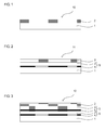
- FIG. 1 is a schematic sectional view illustrating an example of the backsheet for photovoltaic module in the present embodiment.
- the backsheet 10 for photovoltaic module in the present embodiment has a configuration comprising a hydrolysis-resistant film 1 and a resin film 2 laminated thereon.
- the backsheet 10 for photovoltaic module in the present embodiment characteristically has the hydrolysis-resistant film 1 of a polyester resin having a carboxy end-group content of 15 equivalent/ton or less and the resin film 2 of a polypropylene resin.
- the backsheet for photovoltaic module in the present embodiment may have a configuration other than that comprising the hydrolysis-resistant film and the resin film.
- FIG. 2 is a schematic sectional view illustrating another configuration having a gas barrier film in addition to the hydrolysis-resistant film and the resin film.
- the backsheet 11 for photovoltaic module in the present embodiment may have a gas barrier film 5 between a hydrolysis-resistant film 1 and a resin film 2.
- the gas barrier film 5 used in the present embodiment normally has a base film 3 and a gas-barrier layer 4 formed on the base film.
- the backsheet for photovoltaic module according to the present embodiment wherein the polyester resin for the hydrolysis-resistant film has a carboxy end-group content of 15 equivalent/ton or less, can restrain the progress in hydrolysis reaction of the polyester resin even in high-temperature and high-humidity atmosphere.
- the polypropylene resin for the resin film which has no hydrolytic functional group, is superior in hydrolysis resistance. Therefore, the backsheet for photovoltaic module in the present embodiment having a laminated configuration comprising the hydrolysis-resistant film and the resin film is superior in hydrolysis resistance as a whole, and thus, according to the present embodiment, it is possible to obtain a backsheet for photovoltaic module superior in hydrolysis resistance and thus in durability.
- the backsheet for photovoltaic module in the present embodiment has a resin film of a polypropylene resin as the outmost layer. Because the polypropylene resin is thermally adhesive, the backsheet for photovoltaic module in the present embodiment is characteristically superior in adhesiveness, for example, to other members used in the photovoltaic module such as an encapsulant for photovoltaic module.
- the backsheet for photovoltaic module in the present embodiment comprises a hydrolysis-resistant film and a resin film.
- a hydrolysis-resistant film and a resin film.
- the resin film for the backsheet for photovoltaic module in the present embodiment contains a polypropylene resin and is characteristically superior in hydrolysis resistance.
- the polypropylene resin for the resin film used in the present embodiment will be described.
- the polypropylene resin used in the present embodiment is not particularly limited, if it has properties, such as hydrolysis resistance, weather resistance, heat resistance and light resistance, suitable for the use environment of the photovoltaic modules employing the backsheet for photovoltaic module in the present embodiment and is superior in the temporal stability of the properties above.
- the polypropylene resins include isotactic polypropylene resins (homo polypropylene, random polypropylene, and block polypropylene), syndiotactic polypropylene resins, and atactic polypropylene resins.
- a mixture of two or more polypropylene resins may also be used as the polypropylene resin.
- polypropylene resins in the present embodiment use of an isotactic polypropylene resin is preferable. This is because it is possible to produce a backsheet for photovoltaic module applicable to a wide range of use environment easily, by using the isotactic polypropylene resin.
- the polypropylene resin is not particularly limited, if it contains a polymer prepared by polymerization of propylene.
- the polypropylene resins include propylene homopolymers, copolymers of propylene with other olefinic resins, a mixture of a propylene homopolymer with other resins, copolymers of propylene with other olefinic resins, and mixtures thereof with other resins.
- the polypropylene resin for use is preferably a mixture of the propylene homopolymer with other resins. This is because it is possible by using such a mixture to modify the various physical properties of the resin film, for example, according to the environment where the backsheet for photovoltaic module in the present embodiment is used.
- the propylene homopolymer is not particularly limited, if it is a polymer prepared by polymerization of propylene monomer.
- the propylene homopolymers include low-molecular weight polypropylenes obtained by polymerization of propylene monomer for example by using a cationic polymerization catalyst, and high-molecular weight and highly crystalline isotactic polymers obtained by polymerization of propylene monomer by using a Ziegler Natta catalyst.
- the isotactic polymers normally have a melting point of 164°C to 170°C and a specific density of approximately 0.90 to 0.91.
- the other resin is not particularly limited, if it is a resin compatible with the propylene homopolymer.
- the other resin for use in the present embodiment is, for example, a polyethylene resin or a polyolefin resin.
- the other resin is preferably a copolymer of propylene and other olefinic resins.
- Propylene homopolymers have a relatively high melting point and rigidity, but many copolymers of propylene and other olefinic resins have a relatively low melting point and rigidity, and thus, it is possible to expand the processing temperature range by using such polymers in a mixture.
- a hard resin and a soft resin in combination to improve the bending processability of the backsheet for photovoltaic module in the present embodiment, to prevent whitening thereof, and to improve the dimensional stability and others. Further during production of a photovoltaic module by using the backsheet for photovoltaic module of the present embodiment, it is possible by using such a resin to improve the bonding strength between the resin and the backside encapsulant layer drastically when they are bonded to each other, for example, by vacuum lamination.
- the copolymer of the propylene and other olefinic resins is not particularly limited, if it is compatible with the propylene homopolymer.
- a copolymer of propylene and an ⁇ -olefin is preferably used, and specifically, a random copolymer of propylene and ethylene is used favorably.
- the mixture ratio of the polypropylene homopolymer is not particularly limited, if it is in the range that provides the resin film with desired physical properties for example according to the application of the backsheet for photovoltaic module of the present embodiment. Normally, it is preferably in the range of 5 mass % to 50 mass %, and particularly preferably in the range of 10 mass % to 30 mass %.
- the resin film for use in the present embodiment is, for example, an unstretched film without stretching or a stretched film after stretching in the uniaxial or biaxial direction.
- an unstretched film is used favorably.
- the film may be contracted drastically by thermocompression bonding, resulting in deterioration in productivity, but there is no such problem occurred when an unstretched film is used.
- the backsheet for photovoltaic module in the present embodiment has a configuration of multiple films layered, a stretched film may influence on the shrinkage rate of the entire backsheet, while the influence by an unstretched film is much smaller.
- the resin film used in the present embodiment may contain additives as needed.
- the additives for use in the present embodiment include coloring additives, ultraviolet absorbents, stabilizers, and flame retardants, and the like.
- coloring additives used in the present embodiment include various dyes and pigments covering achromatic colorants such as whitener and blackener and chromatic colorants such as of red, orange, yellow, green, blue, purple and others in color. In the present embodiment, one or more of these coloring additives may be used in combination.
- the whitener is added, aimed at reflecting or diffusing and thus recycling the sunlight for power generation in the photovoltaic device by the backsheet in the photovoltaic module using the backsheet for photovoltaic module of the present embodiment. Addition of such a whitener to the resin film is also effective in giving favorable design and appearance to the photovoltaic module. If the photovoltaic module is installed, for example, on roof, it is possible to reflect or diffuse the reflecting sunlight. In addition, it is possible to improve the durability of the backsheet for photovoltaic module in the present embodiment by adding a whitener having an ultraviolet ray-absorbing action.
- whiteners for use include white pigments such as basic lead carbonate, basic lead sulfate, basic lead silicate, zinc white, zinc sulfide, lithopone, antimony trioxide, anatase titanium oxide, and rutile titanium oxide.
- whiteners may be used alone or as a mixture of two or more in the present invention.
- the addition amount of the whitener in the resin film when added is not particularly limited, if it is in the range of providing the resin film with desired light reflectivity or diffusivity. Normally, it is preferably in the range of 0.1 mass % to 30 mass %, particularly preferably in the range of 0.5 mass % to 10 mass % in the resin film.
- an achromatic dye or pigment of gray in color in combination of a whitener and a blackener described below may be used.
- the blackener is added for providing the film with favorable design and appearance suitable for the ambient environment, for example when the photovoltaic module using the backsheet for photovoltaic module in the present embodiment is installed on roof.
- the blackeners for use include carbon blacks (channel and furnace), iron oxide black, and others, and these blackeners may be used alone or in combination of two or more.
- the black layer formed with the blackener may be a black layer in any color, suchasbrown, brownishblack, orgrayish black.
- the addition amount of the blackener in the resin film when added is not particularly limited, if it is in the range providing the resin film with favorable desired and appearance. Normally, it is preferably in the range of 0.1 mass % to 30 mass %, particularly preferably in the range of 0.5 mass % to 10 mass % in the resin film.
- the chromatic colorant of dye or pigment is added for providing the film with favorable design and appearance suitable for the ambient environment, for example when the photovoltaic module using the backsheet for photovoltaic module in the present embodiment is installed on roof.
- the colorants include organic dye/pigment-based colorants such as azo colorants, anthraquinone colorants, phthalocyanine colorants, thioindigo colorants, quinacridone colorants, and dioxazine colorants; and inorganic pigment-based colorants such as iron blue, chrome vermilion, andbengala.
- organic dye/pigment-based colorants such as azo colorants, anthraquinone colorants, phthalocyanine colorants, thioindigo colorants, quinacridone colorants, and dioxazine colorants
- inorganic pigment-based colorants such as iron blue, chrome vermilion, andbengala.
- use of a bluish colorant is preferable.
- the colorant is more favorable
- the addition amount of the colorant in the resin film when added is not particularly limited, if is in the range providing the resin film with favorable appearance. Normally, it is preferably in the range of 0.1 mass % to 30 mass %, particularly preferably in the range of 0.5 mass % to 10 mass % in the resin film.
- the ultraviolet absorbent used in the present embodiment is an agent for absorbing harmful ultraviolet rays in the sun light and converting the ultraviolet rays into harmless heat energy in the molecules and accordingly preventing excitation of the active species which initiate photo-deterioration in the resin film.
- one kind or two or more of inorganic type ultraviolet absorbents selected from a group of consisting of benzophenone type, benzotriazole type, salicylate type, acrylonitrile type, metal complex salt type, hindered amine type ultraviolet absorbents, ultra fine particles of titanium oxide (particle diameter: 0.01 ⁇ m to 0.06 ⁇ m), and ultra fine particles of zinc oxide (particle diameter: 0.01 ⁇ m to 0.04 ⁇ m) can be used.
- the addition amount of the ultraviolet absorbent in the resin film when added is not particularly limited, if it is in the range providing the resin film with favorable ultraviolet-absorbing efficiency. Normally, it is preferably in the range of 0.1 mass % to 10 mass %, particularly preferably in the range of 0.3 mass % to 10 mass % in the support.
- the light stabilizer used in the present embodiment is an agent for catching active species which initiate photo-deterioration in the resin film and accordingly preventing photooxidation.
- active species which initiate photo-deterioration in the resin film and accordingly preventing photooxidation.
- one kind or two or more of compounds selectedfrom hindered aminetype compounds, hinderedpiperidine type compounds, and others can be used in the present embodiment.
- the addition amount of the light stabilizer in the resin film when added is not particularly limited, if it is in the range providing the resin film with favorable light stability. Normally, it is preferably in the range of 0.1 mass % to 10 mass %, particularly preferably in the range of 0.3 mass % to 10 mass % in the support.
- the resin film used in the present embodiment preferably contains a flame retardant.
- the flame retardants for use in the present embodiment include both organic and inorganic flame retardants.
- Examples of the organic flame retardants include phosphorus-based,phosphorusand halogen-based,chlorine-based, andbromine-based flame retardants
- examples of the inorganic flame retardants include aluminum hydroxide, antimony-based flame retardants, magnesium hydroxide, guanidine-based and zirconium-based retardants, and zinc borate.
- the thickness of the resin film used in the present embodiment is not particularly limited, and may be determined for example according to the application of the backsheet for photovoltaic module in the present embodiment. Normally, it is preferably in the range of 10 ⁇ m to 300 ⁇ m, particularly preferably in the range of 15 ⁇ m to 150 ⁇ m.
- the resin film used in the present embodiment preferably has a heat shrinkage rate at 150°C for 30 minutes of 3.0% or less, more preferably 1.0% or less, and particularly preferably in the range of 0.5% to 0.3%. It is because when the heat shrinkage rate of the resin film is in the range above, the resin film is less influential on the shrinkage rate of the backsheet for photovoltaic module of the present invention and makes it easier to produce a backsheet for photovoltaic module superior in appearance.
- the heat shrinkage rate can be determined according to the Testing methods of plastic films for electrical purposes specified in JIS C2151.
- the method of producing the resin film used in the present embodiment is not particularly limited, if it is a method giving a uniform film having a desired thickness.
- Methods of producing such a resin film include: a solution casting method of forming a film by casting on a support a polypropylene resin solution containing the polypropylene resin described above dissolved in a solvent; and a melt-casting method of forming a film by melt-extruding a polypropylene resin composition containing a meltage of polypropylene resin.
- the resin film is particularly preferably produced by the melt-casting method. It is because the melt-casting method is lower in production cost than the solution casting method, and does not require a drying step, and thus allows acceleration of the casting speed.
- a polypropylene resin film is produced, for example, by preparing a polypropylene resin composition by adding above-mentioned additives to the polypropylene resin, blending the mixture thoroughly, and then, forming a film, for example by extrusion method, T die extrusion method, cast molding method, inflation molding, or other film-forming method.
- the polypropylene resin film formed may be stretched as needed by a tenter or tubular method in the uniaxial or biaxial direction.
- the hydrolysis-resistant film used in the backsheet for photovoltaic module in the present embodiment is characteristically made of a polyester resin having a carboxy end-group content of 15 equivalent/ton or less.
- the polyester resin for the hydrolysis-resistant film used in the present embodiment will be describedbelow.
- the polyester resin used in the present embodiment is characteristically made of a polyester resin having a carboxy end-group content of 15 equivalent/ton or less.
- the polyester resin for use in the present embodiment has a carboxy end-group content of 15 equivalent/ton or less.
- the carboxy end-group content of a polyester resin is defined as described above, because, when the carboxy end-group content is larger than the range above, hydrolysis reaction of the polyester resin progresses under high-temperature high-humidity atmosphere, damaging the durability of the backsheet for photovoltaic module in the present embodiment.
- the carboxy end-group content is more preferably in the range of 12 equivalent/ton to 5 equivalent/ton.
- the terminal carboxyl group amount in the present embodiment is determined by dissolving the hydrolysis-resistant film used in the present embodiment in a particular amount in o-cresol/chloroform (weight ratio: 50/50 or 60/40), phenol/1,2-dichlorobenzene (weight ratio: 50/50), phenol/1,1,2,2-tetrachloroethane (weight ratio: 50/50 or 60/40), O-chlorophenol, or dichloroacetic acid and titrating the solution with alkali potentiometrically.
- o-cresol/chloroform weight ratio: 50/50 or 60/40
- phenol/1,2-dichlorobenzene weight ratio: 50/50
- phenol/1,1,2,2-tetrachloroethane weight ratio: 50/50 or 60/40
- O-chlorophenol or dichloroacetic acid
- the polyester resin for use in the present embodiment preferably has an intrinsic viscosity of 0.8 dl/g or more.
- Use of the polyester resin having an intrinsic viscosity of 0.8 dl/g or more makes the backsheet for photovoltaic module of the present invention superior in toughness, rigidity, and heat resistance.
- the intrinsic viscosity is more preferably 1.0 dl/g or more, and still more preferably in the range of 1.2 dl/g to 1.5 dl/g.
- the intrinsic viscosity is a viscosity as determined by dissolving the hydrolysis-resistant film used in the present embodiment in a solvent such as phenol/1,2-dichlorobenzene (weight ratio: 50/50), phenol/1,1,2,2-tetrachloroethane (weight ratio: 50/50 or 60/40), O-chlorophenol, or dichloroacetic acid at a concentration of 0.1 g/ml and measuring the viscosity of the dissolved solution at 25°C.
- a solvent such as phenol/1,2-dichlorobenzene (weight ratio: 50/50), phenol/1,1,2,2-tetrachloroethane (weight ratio: 50/50 or 60/40), O-chlorophenol, or dichloroacetic acid at a concentration of 0.1 g/ml and measuring the viscosity of the dissolved solution at 25°C.
- the specific viscosity ⁇ sp is a function of the concentration of the desired substance, and the specific viscosity extrapolated to a concentration of 0 is the intrinsic viscosity (limiting viscosity).
- the intrinsic viscosity is a physical parameter that can be correlated with the particle diameter and the molecular weight of the solute present as dispersed in the solution and thus, contains useful information.
- the viscosity of the solution is a value obtained according to the test method of Plastics - Determination of the viscosity of polymers in dilute solution using capillary viscometers - Part 5: Thermoplastic polyester (TP) homopolymers and copolymers specified in JIS K7367-5.
- the content of oligomers in the polyester resin for use in the present embodiment is preferably in the range providing the hydrolysis-resistant film with favorable hydrolysis resistance for example according to the application of the backsheet for photovoltaic module in the present embodiment.
- the oligomer content has correlation with the carboxy end-group content in the polyester resin. Increase of the oligomeric content leads to increase of the carboxy end-group content and further, to deterioration of the hydrolysis resistance. Decrease of the oligomeric content leads to decrease of the carboxy end-group content and further to improvement of the hydrolysis resistance.
- the content of the oligomers in the polyester resin is preferably in the range of 0.4 mass % or less, more preferably in the range of 0.3 mass % to 0.1 mass %, and particularly preferably in the range of 0.2 mass % to 0.1 mass %.
- the oligomer means low-molecular weight polymers having a repetition number (polymerization degree) of the polyester resin-constituting structural units of about 2 to 20.
- the content of oligomers in the polyester resin is determined for example, by dissolving the polyester resin in an amount of 100 mg in 2 ml of a solvent such as phenol/1,2-dichlorobenzene (weight ratio: 50/50), phenol/1,1,2,2-tetrachloroethane (weight ratio: 50/50 or 60/40), O-chlorophenol, or dichloroacetic acid and analyzing the solution by liquid chromatography (HLC803D, manufactured by Toso Sangyo Co. Ltd.), and is expressed as a oligomer rate (mass %) with respect to the polyester resin.
- a solvent such as phenol/1,2-dichlorobenzene (weight ratio: 50/50), phenol/1,1,2,2-tetrachloroethane (weight ratio: 50/50 or 60
- the number-average molecular weight of the polyester resin for use in the present embodiment is preferably in the range providing the hydrolysis-resistant film with favorable hydrolysis resistance for example according to the application of the backsheet for photovoltaic module in the present embodiment.
- the number-average molecular weight has correlation with the carboxy end-group content in the polyester resin film; increase of the number-average molecular weight leads to decrease of the carboxy end-group content and improvement in the hydrolysis resistance; and on the other hand, decrease of the number-average molecular weight leads to increase of the carboxy end-group content and thus to improvement in the hydrolysis.
- the number-average molecular weight is preferably in the range of 18, 500 to 40, 000, more preferably in the range of 19,000 to 35,000.
- the number-average molecular weight is a value obtained by GPC (gel permeation chromatography) under the following condition:
- the polyester resin for use in the present embodiment is not particularly limited, if it is a resin having a carboxy end-group content in the range above and that is produced from a dicarboxylic acid compound and a diol compound in condensation.
- the dicarboxylic acid compound for the polyester resin used in the present embodiment is not particularly limited, and, for example, an aromatic dicarboxylic acid, an alicyclic dicarboxylic acid, or a fatty dicarboxylic acid may be used.
- aromatic dicarboxylic acid components for the aromatic dicarboxylic acid include terephthalic acid, isophthalic acid, phthalic acid, 1,4-naphthalenedicarboxylic acid, 1,5-naphthalenedicarboxylic acid, 2,6-naphthalenedicarboxylic acid, 4,4'-diphenyldicarboxylic acid, 4,4'-diphenyletherdicarboxylic acid, and 4,4'-diphenylsulfonedicarboxylic acid.
- terephthalic acid, phthalic acid or 2,6-naphthalenedicarboxylic acid is used favorably.
- Examples of the alicyclic dicarboxylic acids include cyclohexanedicarboxylic acid.
- fatty dicarboxylic acid components examples include adipic acid, suberic acid, sebacic acid, and dodecandionic acid.
- the dicarboxylic acid compounds may be used alone or in combination of two or more, and an oxy acid such as hydroxyethoxybenzoic acid may be copolymerized partly.
- the diol compound for the polyester resin for use in the present embodiment is not particularly limited, if it gives a polyester resin by condensation with the dicarboxylic acid above .
- the diol compounds for use in the present embodiment include ethylene glycol, 1,2-propanediol, 1,3-propanediol, neopentylglycol, 1,3-butanediol, 1,4-butanediol, 1,5-pentanediol, 1,6-hexanediol, 1,2-cyclohexanedimethanol, 1,3-cyclohexanedimethanol, 1,4-cyclohexanedimethanol, diethylene glycol, triethylene glycol, polyalkylene glycols, and 2,2'-bis(4'- ⁇ -hydroxyethoxyphenyl)propane.
- use of ethylene glycol, 1,4-butanediol, 1,4-cyclohexanedimethanol use of ethylene glyco
- the diol components may be used alone or in combination of two or more.
- the polyester resin formed by condensation of the dicarboxylic acid compound and the diol compound is not particularly limited, and any polyester resin prepared in any combination of the dicarboxylic acid compound and the diol compound may be used.
- any polyester resin prepared in any combination of the dicarboxylic acid compound and the diol compound may be used.
- use of polyethylene terephthalate, polyethylene naphthalate, or polyethylene 2,6-naphthalenedicarboxylate is preferable, and use of polyethylene terephthalate is most preferable.
- the polyester resin is prepared by condensation of the dicarboxylic acid compound and the diol compound
- the polyester resin may be copolymerized with other compounds including trimellitic acid, pyromellitic acid, glycerol, pentaerythritol, 2,4-dioxybenzoic acid, and monofunctional compounds such as lauryl alcohol and phenyl isocyanate, if the resulting polymer remains substantially linear.
- the polyester resin in the present embodiment is produced, for example, by: a method of esterifying an acid component directly with a diol component; a method of using a dialkyl ester as the acid component, carrying out a first-phase reaction with the diol component by ester-exchange reaction, and subsequently carrying out a second-phase reaction of melt-polymerizing the reaction product while removing the excess diol component while heated under reduced pressure; or a method of further carrying out a third-phase reaction of polymerizing the second-phase reaction product in the solid phase.
- the method of the solid-phase polymerization is not particularly limited, and any known method may be used.
- the resin may be crystallized preliminary at a temperature of 180°C or lower and then heated under nitrogen stream or under vacuum at 1 torr or lower at a temperature in the range of 180°C to the melting point (approximately 250°C) for 5 to 50 hours.
- the polyester resin for use in the present embodiment may contain, for example, a polyether compound additionally for adjustment of the intrinsic viscosity in a desired range.
- the polyether compound for use in the present embodiment is not particularly limited, and, for example, polyethyleneoxide or a polyether compound containing a diol as the principal component may be used.
- diol examples include ethylene glycol, 1,2-propanediol, 1,3-propanediol, neopentylglycol, 1,3-butanediol, 1,4-butanediol, 1,5-pentanediol, 1,6-hexanediol, 1,2-cyclohexanedimethanol, 1,3-cyclohexanedimethanol, 1,4-cyclohexanedimethanol, diethylene glycol, triethylene glycol, polyalkylene glycols, and 2,2'-bis(4'- ⁇ -hydroxyethoxyphenyl)propane.
- the polyether compound favorably used in the present embodiment is, for example, a polyether compound containing at least one polymer selected from the group consisting of polyethyleneoxide, polyethylene glycol, polypropylene glycol, polytetramethylene glycol, and the copolymers of these polyether compounds.
- the polyether compound for use may be a terminal-blocked polyether compound. It is because the terminal-blocked polyether compound advantageously inhibits hydrolysis of the polyester resin.
- the terminal-blocked polyether compound is, for example, a polyether compound with its polyether terminal hydroxyl groups alkyletherified, i.e., terminal-blocked with a methoxy, ethoxy or other group.
- the average molecular weight of the polyether compound is not particularly limited, but preferably 500 to 10, 000, more preferably 700 to 5,000.
- An average molecular weight of less than 500 is disadvantageous, because the compound is less soluble in the polyester resin.
- an average molecular weight of more than 10,000 may lead to deterioration in compatibility with the polyester resin.
- the content of the polyether compound for use in the present embodiment is not particularly limited. Normally, it is preferably in the range of 0.1 mass % to 10 mass %, more preferably in the range of 0.2 mass % to 7 mass %, and particularly preferably in the range of 0.2 mass % to 5 mass %, in the polyester resin.
- the polyester resin for use in the present embodiment may contain as needed various additives such as flame retardant, heat stabilizer, antioxidant, ultraviolet absorbent, antistatic agent, pigment and dye, organic lubricant such as fatty acid ester or wax, and antifoam such as polysiloxane.
- various additives such as flame retardant, heat stabilizer, antioxidant, ultraviolet absorbent, antistatic agent, pigment and dye, organic lubricant such as fatty acid ester or wax, and antifoam such as polysiloxane.
- inorganic particles such as of clay, mica, titanium oxide, calcium carbonate, kaolin, talc, wet or dry silica, colloidal silica, calcium phosphate, barium sulfate, alumina, and zirconia, and organic particles such as resins containing an acrylic acid or styrene as the constituent component maybe added; so-called internal particles that precipitate by addition of a catalyst or the like during polyester polymerization reaction may be added; and also, a surfactant may be added.
- the apparent density of the hydrolysis-resistant film used in the present embodiment is not particularly limited, if it is the range providing the hydrolysis-resistant film with favorable mechanical strength, for example according to the application of the backsheet for photovoltaic module in the present embodiment.
- the apparent density is preferably in the range of 1.37 g/cm 3 to 0.85 g/cm 3 , more preferably in the range of 1.35 g/cm 3 to 0 . 9 g/cm 3 , and particularly preferably in the range of 1.3 g/cm 3 to 0.9 g/cm 3 .
- the apparent density can be determined by measuring the mass of a hydrolysis-resistant film with known volume.
- the thickness of the hydrolysis-resistant film used in the present embodiment is not particularly limited and may be determined arbitrarily in the range providing the backsheet for photovoltaic module in the present embodiment with desired self-supporting properties.
- the thickness is preferably in the range of 3 ⁇ m to 500 ⁇ m, more preferably in the range of 25 ⁇ m to 250 ⁇ m, and particularly preferably in the range of 25 ⁇ m to 188 ⁇ m.
- the thickness for use is a value as determined according to the Testing methods of plastic films for electrical purposes specified in JIS C2151.
- the specific volume resistivity of the hydrolysis-resistant film used in the present embodiment is preferably approximately 1 ⁇ 10 18 ⁇ /cm; the dielectric breakdown voltage thereof, in the range of 5 to 50 kV; and the dielectric constant, approximately 3.3 (1kHz).
- the hydrolysis-resistant film used in the present embodiment may have a single-layered structure or a multi-layered structure.
- the multi-layered structure is not particularly limited, but it is, for example, a layered structure having a film of the polyester resin and another polymer layer of such as polyester, polyolefin, polyamide, polyvinylidene chloride, or acrylic polymer laminated thereon.
- the hydrolysis-resistant film used in the present embodiment preferably has a heat shrinkage rate at 150°C for 30 minutes of 1.0% or less, more preferably 0.5% or less, and most preferably in the range of 0.1% to 0.5%.
- a heat shrinkage rate at 150°C for 30 minutes of 1.0% or less, more preferably 0.5% or less, and most preferably in the range of 0.1% to 0.5%.
- the heat shrinkage rate can be determined according to the Testing methods of plastic films for electrical purposes specified in JIS C2151.
- the method of producing a hydrolysis-resistant film for use in the present embodiment is not particularly limited, if it is a method of forming a film uniformly at a desired thickness. Description on the method of forming a hydrolysis-resistant film is omitted, because a method similar to that of producing a resin film described in the section of "1. Resin film" may be used as the method.
- the backsheet for photovoltaic module in the present embodiment may have components other than the resin film and the hydrolysis-resistant film.
- An example of such a component is a gas barrier film.
- the backsheet particularly preferably has a gas barrier film for improvement in moisture barrier characteristics thereof.
- the gas barrier film for use in the present embodiment will be described.
- the gas barrier film is not particularly limited, if it has a function to provide the backsheet for photovoltaic module in the present embodiment with desired moisture barrier characteristics.
- a configuration consisting of a base film and a gas-barrier layer formed on at least one surface of the base film is used.
- the embodiment of such gas barrier film that is formed on the backsheet for photovoltaic module in the present embodiment is not particularly limited, if it is a filmproviding the backsheet for photovoltaic module in the present embodiment with desired moisture barrier characteristics and allowing stable preservation of the desired moisture barrier characteristics for a long period of time.
- Such embodiments include: an embodiment of laminating a gas barrier film on the hydrolysis-resistant film; an embodiment of laminating a gas barrier film on the resin film; and an embodiment of forming a gas barrier film between the hydrolysis-resistant film and the resin film.
- Alternatively when multiple gas barrier films are used, a combination of the embodiments above may be used.
- the embodiment of forming a gas barrier filmbetween the hydrolysis-resistant film and the resin film is preferable. In such a configuration, it is possible to improve the temporal stability of the moisture barrier characteristics.
- the backsheet for photovoltaic module 11 exemplified in FIG. 2 is an embodiment having a gas barrier film 5 comprising a base film 3 and a gas-barrier layer 4 formed between the hydrolysis-resistant film 1 and the resin film 2.
- the gas barrier film 5 is formed with its the gas-barrier layer 4 facing the hydrolysis-resistant film 1, but gas barrier film 5 may be formed in the opposite configuration, i.e., with the gas-barrier layer 4 facing the resin film 2.
- the number of the gas barrier films is not particularly limited, and may be one, or two or more.
- the number of the gas barrier films used is determined suitably, for example according to the application of the backsheet for photovoltaic module in the present embodiment, by taking into consideration the moisture barrier characteristics required for the backsheet for photovoltaic module and the moisture barrier characteristics of the gas barrier film. In particular for simplification of the production process of the backsheet for photovoltaic module of the present embodiment, use of one or two gas barrier films is preferable.
- FIG. 3 is a schematic sectional view illustrating an example of the backsheet for photovoltaic module in the present embodiment having two gas barrier films.
- An embodiment of the case when two gas barrier films are used in the backsheet for photovoltaic module of the present embodiment is the configuration shown in FIG. 3 , wherein two gas barrier films 5 comprising a base film 3 and a gas-barrier layer 4 are formed between the hydrolysis-resistant film 1 and the resin film 2.
- FIG. 4 is a schematic sectional view illustrating another embodiment wherein the backsheet for photovoltaic module in the present embodiment has two gas barrier films.
- the backsheet for photovoltaic module in the present embodiment has two gas barrier films.
- two gas barrier films 5 laminated via a tough film 6 are placed between the hydrolysis-resistant film 1 and the resin film 2.
- the material for the base film for use in the present embodiment is not particularly limited, if it has a durability withstanding the processing condition during the gas-barrier layer described below is formed and is adhesive to the gas-barrier layer, and favorable materials may be selected suitably according to the various physical properties required for the backsheet for photovoltaic module in the present embodiment.
- the materials for the base film include: polyethylene resins, polypropylene resins, cyclic polyolefin resins, polystyrene resins such as syndiotactic polystyrene resin, acrylonitrile-styrene copolymers (AS resins), acrylonitrile-butadiene-styrene copolymers (ABS resins), polyvinylchloride resins, fluorine resins, poly (meth)acrylic resins, polycarbonate resins, polyester resins such as polyethylene terephthalate and polyethylene naphthalate, polyamide resins such as various nylons, polyimide resins, polyamide-imide resins, polyaryl phthalate resins, silicone resins, polysulfone resins, polyphenylenesulfide resins, polyethersulfone resins, polyurethane resins, acetal resins, and cellulosic resins.
- polyethylene resins polypropylene resins
- a cyclic polyolefin resin a polycarbonate resin, a poly (meth) acrylic resin, a polystyrene resin, a polyamide resin or a polyester resin is preferable. This is because it is possible by using such a material to make the backsheet for photovoltaic module in the present embodiment favorable in durability and superior in processing compatibility.
- the materials for the base film described above may be used alone or in combination of two or more.
- the thickness of the base film may be determined properly according to the various physical properties required for the backsheet for photovoltaic module of the present embodiment. Normally, it is preferably in the range of 9 ⁇ m to 300 ⁇ m, more preferably in the range of 12 ⁇ m to 200 ⁇ m.
- the base film may contain as needed other additives.
- the additives used in the present embodiment include lubricant, crosslinking agent, antioxidant, ultraviolet absorbent, light stabilizer, encapsulant, lubricant, reinforced fiber, reinforcing agent, antistatic agent, flame retardant, flame resistant agent, foaming agent, fungicide, and pigment, as well as modifying resin.
- lubricant crosslinking agent, antioxidant, ultraviolet absorbent, light stabilizer, encapsulant, lubricant, reinforced fiber, reinforcing agent, antistatic agent, flame retardant, flame resistant agent, foaming agent, fungicide, and pigment, as well as modifying resin.
- use of an ultraviolet absorbent, a light stabilizer, and an antioxidant is preferable.
- one kind or more of inorganic type ultraviolet absorbents selected from a group of consisting of benzophenone type, benzotriazole type, salicylate type, acrylonitrile type, metal complex salt type, ultra fineparticles of titanium oxide (particle diameter: 0.01 ⁇ m to 0.06 ⁇ m), and ultra fine particles of zinc oxide (particle diameter: 0.01 ⁇ m to 0.04 ⁇ m) can be used.
- the light stabilizer one kind or more of compounds selectedfrom hindered aminetype compounds, hinderedpiperidine type compounds, and others can be used.
- the antioxidant is a compound preventing oxidative degradation and others of base film caused by for example light or heat, and examples thereof for use include phenol-based, amine-based, sulfur-based, phosphoric acid-based, and other antioxidants.
- ultraviolet absorbents, light stabilizers and antioxidants for use include polymeric ultraviolet absorbents, light stabilizers or antioxidants containing chemically bonded an ultraviolet absorbent such as benzophenone, a light stabilizer such as a hindered amine compound, or an antioxidant such as a phenol-based antioxidant on the main or side chains of the polymer.
- the contents of the ultraviolet absorbent, light stabilizer and antioxidant are determined according to the various physical properties required for the base film. Normally, they are preferably in the range of 0.1 mass to 10 mass % in the base film.
- the base film may have a surface-finished layer previously formed.
- the surface-finished layers include corona-treated layer, ozone-treated layer, plasma-treated layer, and oxidized layer that are formed respectively by corona discharge treatment, ozone treatment, plasma treatment by using gas such as oxygen or nitrogen, glow discharge treatment, and chemical surface treatment for example by oxidation with a chemical.
- the surface treatment may be carried out in a separate step, or for example, when surface treatment such as plasma treatment or glow discharge treatment is performed, the surface treatment may be carried out as in-line pretreatment before an inorganic-oxide vapor-deposition film described below is formed, and such a method is advantageously effective in reducing the production cost.
- the surface-finished layer is formed as the means of improving the adhesiveness between the base film and the gas-barrier layer described below.
- a coating agent layer such as primer coating agent layer, undercoat agent layer, anchor-coating agent layer, adhesive agent layer, or vapor deposition anchor-coating agent layer may be formed on the surface of the base film, as the means of improving the adhesiveness.
- Examples of the materials for the coating agent layer include polyester resins, polyamide resins, polyurethane resins, epoxy resins, phenol resins, (meth)acrylic resins, polyvinyl acetate resins, polyolefin resins such as polyethylene and polypropylene, and the copolymers or the modified resins thereof, and cellulosic resins.
- a vapor-deposition protective film may be formed on at least one surface of the base film for protection of the base film.
- a vapor-deposition thin film of inorganic oxide is formed on a base film, for example, by a chemical vapor deposition method (CVD method) such as chemical vapor deposition method, thermochemical vapor deposition method, or photochemical vapor deposition method, or a physical vapor deposition method (PVD method) such as vacuum deposition method (resistance-heating, induction-heating, or EB-heating), sputtering method, or ion plating method.
- CVD method chemical vapor deposition method
- PVD method physical vapor deposition method
- the inorganic oxide for the vapor-deposition protective film is not particularly limited, but, for example, silicon oxide may be used.
- the thickness of the vapor-deposition protective film is desirably less than 150 ⁇ . More specifically, it is preferably in the range of 10 to 100 ⁇ , more preferably in the range of 20 to 80 ⁇ , and particularly preferably in the range of 30 to 60 ⁇ . A film thickness of larger than the range above may make it difficult to form a uniformvapor-deposition protective film, while a film thickness of smaller than the range may result in insufficient protection of the base film.
- the gas-barrier layer in the gas barrier film is not particularly limited, if it can provide the gas barrier film with desired moisture barrier characteristics, and examples thereof include thin metal film, vapor-deposited inorganic oxide film, and organic thin film, as well as the films in combination thereof. Particularly in the present embodiment, a vapor-deposited inorganic oxide film is used favorably. It is because the vapor-deposited inorganic oxide film, which is superior in denseness, has favorable moisture barrier characteristics per unit thickness and is superior in adhesiveness to the base film.
- the vapor-deposited inorganic oxide film for use in the present embodiment is not particularly limited, if it is a thin film of a vapor-deposited metal oxide.
- the metals used for the vapor-deposition film include silicon (Si), aluminum (Al), magnesium (Mg), calcium (Ca), potassium (K), tin (Sn), sodium (Na), boron (B), titanium (Ti), lead (Pb), zirconium (Zr), and yttrium (Y).
- a vapor-deposition metal oxide film of silicon (Si) or aluminum (Al) is favorably used as the vapor-deposition film.
- the content of oxygen atom in the metal oxide is not particularly limited, and may be determined arbitrarily according to the metal species of the metal oxide.
- the metal oxide may be expressed by MOx, wherein the metal element is represented by M , the oxygen atom by O , and the number of the oxygen atoms by X .
- X is preferably 0 to 2.
- silicon (Si) or aluminum (Al) is used as the metal constituting the metal oxide, the value X is preferably in the range of 1.0 to 2.0 in the case of silicon (Si), and in the range of 0.5 to 1.5 in the case of aluminum (Al).
- the metal for use in the vapor-deposited inorganic oxide film may be a pure metal or an alloy of two or more metals, and the film may be a vapor-deposited inorganic oxide film of different metals.
- the thickness of the vapor-deposited inorganic oxide film is normally, preferably in the range of 50 to 4000 ⁇ , particularly preferably in the range of 100 to 1000 ⁇ , according to factors such as the kind of the metal or metal oxide used.
- the thickness above denotes to the total thickness.
- the gas-barrier layer used in the present embodiment may have a single-layer structure or a multi-layered structure. When it has a multi-layered structure, it may be lamination of layers in the same composition or of layers different in composition.
- the gas barrier properties of the gas-barrier layer used in the present embodiment are not particularly limited, if they are in the range providing the backsheet for photovoltaic module in the present embodiment with desired moisture barrier properties according to the use embodiment of the gas barrier film.
- the oxygen gas permeability of the gas barrier film for use in the present embodiment is preferably 1 cc/m 2 /day/atm or less, particularly preferably 0.5 cc/m 2 /day/atm or less.
- the moisture permeability is preferably 1 g/m 2 /day or less, particularly preferably 0.5 g/m 2 /day or less.
- the oxygen gas permeability is a value as determined by using an oxygen gas permeability analyzer (trade name: OX-TRAN 2/20, manufactured by MOCON Inc.) under the condition of a measurement temperature of 23°C and a humidity of 90% RH.
- the moisture permeability is a value as determined by using a moisture permeability analyzer (trade name: PERMATRAN-W3/31, manufactured by MOCON Inc.) under the condition of a measurement temperature 37.8°C and a humidity of 100% RH.
- the configuration of the gas barrier film for use in the present embodiment is not particularly limited, if favorable gas barrier properties are obtained, but it is preferably a configuration in which the gas-barrier layer is formed at least on one side of the base film. In other words, the gas-barrier layer may be formed only on one side of the base film or on both faces of the base film.
- the method of producing a gas barrier film for use in the present embodiment is not particularly limited, if it can form a uniform gas-barrier layer on the base film, according to the materials for the gas-barrier layer.
- the method of forming it is not particularly limited, if a uniform vapor-deposition film is formed at a desired layer thickness.
- the vapor-deposition film may be formed for example, by physical or chemical vapor deposition method or a method in combination thereof.
- PVD methods physical vapor deposition methods
- vacuum deposition resistance-heating, induction heating, or EB heating
- sputtering ion plating
- ion cluster beam method a vacuum deposition method of vapor-depositing a metal oxide on a base film by using a metal oxide and heating it as a raw material
- an oxidative vapor deposition method of vapor-depositing a metal or metal oxide on a base film by using and heating it as a raw material while the raw material is oxidized by oxygen supplied or an plasma-assisted oxidative vapor deposition method of accelerating the oxidation reaction by plasma.
- the material for vapor deposition may be heated, for example, by resistance heating, high-frequency induction heating, or electron beam heating (EB).
- EB electron beam heating
- Examples of the chemical vapor deposition methods include chemical vapor deposition methods (CVD) such as plasma chemical vapor deposition, thermochemical vapor deposition, and photochemical vapor deposition. More specifically, a vapor-deposited inorganic oxide film for example of silicon oxide is formed on one face of a base film, by using a monomer gas for vapor deposition such as an organic silicon compound as the raw material, an inert gas such as argon or helium gas as the carrier gas and an oxygen gas as the oxygen-supplying gas, and also by using the low-temperature plasma chemical vapor deposition method of using, for example, a low temperature plasma-generating unit. Examples of the low temperature plasma-generating units include high-frequency plasma, pulsed plasma, and microwave plasma-generation apparatuses. In the present embodiment, use of a high-frequency plasma-generating apparatus is preferable for obtaining highly active stabilized plasma.
- CVD chemical vapor deposition methods
- a vapor-deposited inorganic oxide film for example of silicon oxide is formed on one face of a base film, by
- the vapor-deposited inorganic oxide film used in the present embodiment may be a composite film of two or more-layers of vapor-deposited inorganic oxide films different in kind that are formed both by the physical and chemical vapor deposition methods in combination.
- a vapor-deposited inorganic oxide film of such a composite membrane having two or more layers is preferably produced by forming a dense, flexible, vapor-deposited inorganic oxide film relatively resistant to cracking by the chemical vapor deposition method and then forming another vapor-deposited inorganic oxide film by the physical vapor deposition method on the vapor-deposited inorganic oxide film.
- the backsheet for photovoltaic module in the present embodiment may have components other than the gas barrier film.
- the other components include a primer layer for installation of a terminal box.
- the heat shrinkage rate of the backsheet for photovoltaic module in the present embodiment is preferably in such a range that, when a photovoltaic module is prepared by using the backsheet for photovoltaic module of the present embodiment according to the method of producing a backsheet for photovoltaic module of the present embodiment, the backsheet does not deform the photovoltaic module. More specifically, the heat shrinkage rate at 150°C for 30 minutes is preferably 1.0% or less, more preferably 0.5% or less, andparticularly preferably in the range of 0.3% to 0.1%.
- the backsheet shrinks during vacuum lamination, leading to shrinkage of the photovoltaic devices and the lead wires (tags) connecting the photovoltaic devices and consequently to deformation of the lead wire and alternation of the distance between photovoltaic devices.
- a shrinkage rate of 0 is favorable, because there is no contraction (or dislocation, etc.) of the backsheet during vacuum laminate, but such a backsheet only of a plastic film without use of a metal foil as in the present embodiment is rather vulnerable to the influence by heat.
- the heat shrinkage rate can be determined according to the Testing methods of plastic films for electrical purposes specified in JIS C2151.
- the backsheet for photovoltaic module in the present embodiment preferably has through-holes for connection to the terminals to withdraw the electric current generated by the photovoltaic device after production of the photovoltaic module.
- the shape of the through-hole is not particularly limited, and the position, size, shape and number thereof are determined arbitrarily according to factors such as the wiring pattern of the photovoltaic module using the backsheet for photovoltaic module of the present embodiment.
- the method of producing a backsheet for photovoltaic module in the present embodiment is not particularly limited, if it is a method of laminating respective components of the backsheet for photovoltaic module in the present embodiment described above to each other effectively.
- the resin film is dry-laminated via an adhesive agent layer onto the hydrolysis-resistant film.
- a hydrolysis-resistant film and a resin film may be dry-laminated on both faces of the gas barrier film via an adhesive agent layer.
- Examples of the adhesive agents for lamination constituting the adhesive agent layer include: polyvinyl acetate-based adhesive agents; polyacrylic ester-based adhesive agents such as homopolymers of acrylic acid ethyl, butyl, 2-ethylhexyl, or other ester or the copolymers thereof with methyl methacrylate, acrylonitrile, styrene or the like; cyanoacrylate-based adhesive agents; ethylene copolymer-based adhesive agents such as copolymers of ethylene with a monomer such as vinyl acetate, ethyl acrylate, acrylic acid, or methacrylic acid; polyolefin-based adhesive agents such as of a polyethylene resin or a polypropylene resin; cellulosic adhesive agents; polyester-based adhesive agents; polyamine-based adhesive agents; polyimide-based adhesive agents; amino resin-based adhesive agents of a urea resin or a melamine resin; phenol resin-based adhesive agents; epoxy-based adhesive agents; polyurethan
- the adhesive agent may be in any type such as aqueous type, solution type, emulsion type, or dispersion type and in any shape such as sheet-shaped, powdery or solid; and the adhesion mechanism may be chemical reaction, solvent vaporization, heat fusion, thermocompression, or the like.
- a rubber-based adhesive agent such as styrene-butadiene rubber or styrene-isoprene rubber as the adhesive agent is preferable. This is because it is a resin superior in hydrolysis resistance and most suitable for the low-temperature resistance required in present applications.
- the adhesive agent layer preferably contains a hardening agent or crosslinking agent additionally for crosslinking the adhesive agent. This is because it is possible to obtain an adhesive agent layer superior in heat resistance, moist heat resistance and others by forming a crosslinked structure.
- the hardening or crosslinking agent is, for example, an isocyanate compound such as aliphatic-alicyclic isocyanate or aromatic isocyanate, more specifically, 1,6-hexamethylene diisocyanate (HDI), isophorone diisocyanate (IPDI), tolylene diisocyanate (TDI), diphenylmethane diisocyanate (MDI), naphthylene diisocyanate (NDI), tolidine diisocyanate (TODI), or xylylene diisocyanate (XDI).
- an isocyanate compound such as aliphatic-alicyclic isocyanate or aromatic isocyanate, more specifically, 1,6-hexamethylene diisocyanate (HDI), isophorone diisocyanate (IPDI), tolylene diisocyanate (TDI), diphenylmethane diisocyanate (MDI), naphthylene diisocyanate (NDI), tolidine diis
- the adhesive agent is applied onto the gas barrier film, hydrolysis-resistant film, and resin film, for example, by a coating method such as roll coating, gravure roll coating, or kiss coating or a printing process.
- the coating amount is preferably in the range of 0.1 to 10 g/m 2 (dry state).
- the adhesive agent may contain the ultraviolet absorbent or the light stabilizer described above for prevention of ultraviolet deterioration.
- the ultraviolet absorbents or the light stabilizers described above may be used alone or in combination of two or more as the ultraviolet absorbent or the light stabilizer.
- the amount thereof may vary according to factors such as the particle shape and density, but is preferably in the range of 0.1 mass % to 10 mass % in the adhesive agent.
- the gas-barrier layers or the base films maybe laminated as they face each other, or alternatively, a gas-barrier layer and another base film are laminated as they face each other.
- the lamination method is not particularly limited, and, for example, the dry lamination method described above may be used.
- the base film constituting the gas barrier film may face the tough film, or the gas-barrier layer for the gas barrier film may face the tough film.
- the surfaces of the two gas barrier films facing the tough film may be the same as or different from each other.
- the method of laminating two gas barrier films via a tough resin film is not particularly limited, and, for example, the dry laminate method described above may be used.
- a tough resin film or sheet of a polyester resin, a polyamide resin, a polyaramide resin, apolypropyleneresin, apolycarbonateresin, a polyacetal resin, a polystyrene resin, a fluorine resin, or the like can be used as the tough resin film.
- the backsheet for photovoltaic module of the present embodiment comprises: a first hydrolysis-resistant film, a first gas barrier film having a first base film and a first gas-barrier layer formed thereon, a resin film, a second gas barrier film having a second base film and a second gas-barrier layer formed thereon, and a second hydrolysis-resistant film that are laminated in this order, characterized in that at least one of the first hydrolysis-resistant film and the second hydrolysis-resistant film is made of a polyester resin having a carboxy end-group content of 15 equivalent/ton or less, and the resin film is made of a polypropylene resin.
- FIG. 5 is a schematic sectional view illustrating an example of the backsheet for photovoltaic module of the present embodiment.
- the backsheet for photovoltaicmodule in the present embodiment has a configuration comprising a first hydrolysis-resistant film 21a, a first gas barrier film 25a, a resin film 22, a second gas barrier film 25b, and a second hydrolysis-resistant film 21b laminated in this order.
- first gas barrier film 25a has a first base film 23a and a first gas-barrier layer 24a
- second gas barrier film 25b has a second base film 23b and a second gas-barrier layer 24b.
- at least one of the first hydrolysis-resistant film 21a and the second hydrolysis-resistant film 21b is made of a polyester resin having a carboxy end-group content of 15 equivalent/ton or less
- the resin film 22 is made of a polypropylene resin.
- the backsheet for photovoltaic module of the present embodiment it is possible to produce a backsheet for photovoltaic module superior in durability, in which at least one of the first and the second hydrolysis-resistant films is made of a polyester resin having a carboxy end-group content of 15 equivalent/ton or less and the resin film is made of a polypropylene resin superior in hydrolysis resistance. It is possible to obtain a backsheet for photovoltaic module more superior in moisture barrier characteristics, because the backsheet has two gas barrier films, i.e., the first and the second gas barrier films.
- the backsheet for photovoltaic module in such an embodiment will be described.
- the first and second hydrolysis-resistant films, the first and second gas barrier films, and the resin film constituting the backsheet for photovoltaic module of the present embodiment are the same as the hydrolysis-resistant film, the gas barrier film, and the resin film described in the section of "A-1, Backsheet for photovoltaic module in the first embodiment", and thus, description thereof is omitted.
- the combination of the first and second hydrolysis-resistant films used in the present embodiment is determined arbitrarily according to factors such as the durability required for the backsheet for photovoltaic module of the present embodiment. Accordingly, the first and the second hydrolysis-resistant films may be the same as or different from each other. When the first and second hydrolysis-resistant films are different from each other, it means that the films are different not only in the kind of their constituting polyester resins, but also in configuration and function, specifically in film thickness and the kinds of the additives contained in the films.
- the combination of the first and second gas barrier films used in the present embodiment is also determined arbitrarily according to factors such as the moisture barrier characteristics required for the backsheet for photovoltaic module of the present embodiment. Therefore, the first and the second gas barrier films may be the same as or different from each other.
- the first and second gas barrier films are different from each other, it means that the films are different not only in the kinds of the materials for the base film and the gas-barrier layer constituting the films, but also in configuration and function, specifically in film thickness and the kinds of the additives contained in the films.
- the method of producing a backsheet for photovoltaic module of the present embodiment is not particularly limited, if it is a method of laminating the above-mentioned respective components efficiently.
- the dry lamination method described in the section of "A-1. Backsheet for photovoltaic module of first embodiment” may be used as the method of producing a backsheet for photovoltaic module in the present embodiment.
- the dry lamination method is the same as that described in the section of "A-1. Backsheet for photovoltaic module in first embodiment", and thus, the description thereof is omitted.
- backsheet for photovoltaic module in the present embodiment are the same as those in the section of "A-1. Backsheet for photovoltaic module in first embodiment", and the descriptions thereof are omitted.
- the backside laminate for photovoltaic module of the present invention has a backsheet for photovoltaic module in the first embodiment and an encapsulant for photovoltaic module laminated on the resin film of the backsheet for photovoltaic module.
- FIGS. 6A and 6B are each a schematic sectional view illustrating an example of the backside laminate for photovoltaic module of the present invention.
- the backside laminate for photovoltaic module of the present invention 31 has: a backsheet 10 for photovoltaic module in the first embodiment of the present invention, i.e., a laminate of a hydrolysis-resistant film 1 and a resin film 2; and an encapsulant for photovoltaic module 41 formed on the resin film 2.
- the backside laminate for photovoltaic module in the present embodiment employs the backsheet for photovoltaic module in the first embodiment of the present invention described above, and thus, for example as shown in FIG. 6B , it may have a configuration comprising a backsheet for photovoltaic module 11 containing a gas barrier film 5, and an encapsulant for photovoltaic module 41.
- a backside laminate for photovoltaic module giving a photovoltaic module superior in durability, by using a backsheet for photovoltaic module having a hydrolysis-resistant film of the polyester resin having a carboxy end-group content of 15 equivalent/ton or less and a resin filmmade of the polypropylene resin film superior in hydrolysis resistance.
- the backside laminate for photovoltaic module of the present invention has the firstbacksheet forphotovoltaicmodule of the first embodiment and the encapsulant for photovoltaic module.
- firstbacksheet forphotovoltaicmodule of the first embodiment has the firstbacksheet forphotovoltaicmodule of the first embodiment and the encapsulant for photovoltaic module.
- the encapsulant for photovoltaic module for use in the present invention forms a backside encapsulant layer coating the photovoltaic during production of a photovoltaic module by using the backside laminate for photovoltaic module of the present invention.
- the material for the encapsulant for photovoltaic module is not particularly limited, if it is a resin adhesive to the resin film of the backsheet for photovoltaic module, i.e., to the polypropylene resin.
- the resins include: fluorine resins ; ethylene-vinyl acetate copolymers ; ionomer resins ; silane-modified resins ; ethylene-acrylic acid or methacrylic acid copolymers ; polyethylene resins ; polypropylene resins ; acid-modifiedpolyolefin resins obtained by modifying a polyolefin resin such as polyethylene or polypropylene with an unsaturated carboxylic acid such as acrylic acid, itaconic acid, maleic acid, or fumaric acid; polyvinylbutyral resins ; silicone resins ; epoxy resins ; and (meth)acrylic resins.
- these resins may be used alone or as a mixture of two or more.
- silane-modified resin is preferable. It is because the silane-modified resin is superior in adhesiveness to the polypropylene resin constituting the resin film. Also in the present invention, among the silane-modified resins above, favorable is use of a thermoplastic silane-modified resin having a melting point in the range of 50°C to 200°C, more preferably in the range of 60°C to 180°C, and particularly preferably in the range of 65°C to 150°C.
- thermoplastic silane-modified resin By using such thermoplastic silane-modified resin, it is possible to reduce relatively the temperature during thermocompression bonding and prevent, for example, the thermal damage on the hydrolysis-resistant film during production of a photovoltaic module by using the backside laminate for photovoltaic module of the present invention.
- thermoplastic silane-modified resin for use in the present invention is not particularly limited, if it has a melting point in the range above.
- thermoplastic silane-modified resin for use in the present invention having a melt mass flow rate at 190°C of 0.5 to 10 g/10 minutes is preferable, and that of 1 to 8 g/10 minute is more preferable. It is because the resin improves the moldability of the encapsulant for photovoltaic module for use in the present invention.
- a copolymer of a polyolefin compound and an ethylenically unsaturated silane compound is used favorably as the thermoplastic silane-modified resin.
- the copolymer according to the present invention may be crosslinked or may not be crosslinked by a silanol catalyst.
- the copolymer for use in the present invention may be a random copolymer, an alternating copolymer, a block copolymer, or a graft copolymer.
- the copolymer is preferably a graft copolymer, more preferably a graft copolymer containing polyethylene as the polymer main-chain and an ethylenically unsaturated silane compound bound thereto as side-chains. It is because such a graft copolymer makes the freedom degree of the silanol group contributing to the adhesive strength and raises the adhesive strength of the encapsulant for photovoltaic module additionally.
- polyolefin compounds examples include homopolymers of an ⁇ -olefinic having about 2 to 8 carbon atoms, such as ethylene, propylene, or 1-butene; copolymers of the ⁇ -olefin and other ⁇ -olefins having about 2 to 20 carbon atoms such as ethylene, propylene, 1-butene, 3-methyl-1-butene, 1-pentene, 4-methyl-1-pentene, 1-hexene, 1-octene, and 1-decene; and copolymers thereof with vinyl acetate, (meth)acrylic acid, or a (meth)acrylic ester.
- ethylene homopolymers such as low-, medium- and high-density polyethylenes (branched or linear); ethylene resins such as ethylene-propylene copolymer, ethylene-1-butene copolymer, ethylene-4-methyl-1-pentene copolymer, ethylene-1-hexene copolymer, ethylene-1-octene copolymer, ethylene-vinyl acetate copolymer, ethylene-(meth)acrylate copolymer, and ethylene-ethyl (meth) acrylate copolymer; propylene resins such as propylene homopolymer, propylene-ethylene copolymer, and propylene-ethylene-1-butene copolymer; and 1-butene resins such as 1-butene homopolymer, 1-butene-ethylene copolymer, and 1-butene-propylene copolymer. Particularly in the present invention, polyethylene resins are preferable.
- the polyethylene resin for use in the present invention (hereinafter, referred to as polyethylene for polymerization) is not particularly limited, if it is a polyethylene-based polymer.
- the polyethylene-based polymers include low-density polyethylenes, medium-density polyethylenes, high-density polyethylenes, very low-density polyethylenes, ultra low-density polyethylenes, and linear low-density polyethylenes. Also in the present invention, these polyethylene-based polymers may be used alone or as a mixture of two or more.
- the polyethylene for polymerization for use in the present invention is preferably a polyethylene-based polymer having a lower density, and specifically, the density is preferably in the range of 0.850 g/cm 3 to 0.960 g/cm 3 , particularly preferably in the range of 0.865 g/cm 3 to 0.930 g/cm 3 .
- Polyethylene-based polymers having a lower density generally contain many side chains, and thus, are used favorably for graft polymerization. It is because, a density higher than the range above often results in insufficient graft polymerization, occasionally prohibiting provision of desired adhesive strength to the encapsulant for photovoltaic module. A density of lower than the range above often leads to deterioration in mechanical strength of the encapsulant for photovoltaic module.
- the ethylenically unsaturated silane compound used in the present invention it is not particularly limited as long as it is polymerized with the polyethylene for polymerization to form a thermoplastic silane-modified resin.
- it is preferably at least one of the following: vinyltrimethoxysilane, vinyltriethoxysilane, vinyltripropoxysilane, vinyltributoxysilane, vinyltripentyloxysilane, vinyltriphenoxysilane, vinyltribenzyloxysilane, vinyltrimethylenedioxysilane, vinyltriethylenedioxysilane, vinypropionyloxysilane, vinyltriacetoxysilane, and vinyltricarboxysilane.
- the method of producing the graft copolymer is not particularly limited, if it is a method giving a desired yield, and thus, the graft copolymer may be produced by any known polymerization means.
- Particularly favorable in the present invention is a method of obtaining a graft copolymer byheat-fusing and mixing a silane-modified resin composition containing the polyolefin compound, the ethylenically unsaturated silane compound, and a free radical initiator. This is because it is possible to obtain the graft copolymer at high yield by the method.
- the heating temperature during the heat-fusion and mixing is not particularly limited, if it is in the range that the polymerization reaction is completed within a particular period of time. Normally, it is preferably 300°C or lower, more preferably 270°C or lower, and particularly preferably in the range of 160°C to 250°C. It is because a heating temperature lower than the range above may lead to insufficient polymerization reaction, while a heating temperature of higher than the range above may lead to crosslinking of the silanol groups and gelation of the polymer.
- the free radical initiator is not particularly limited, if it is a compound effective in accelerating the polymerization reaction.
- the free radical initiator are organic peroxides, e.g. hydroperoxides such as diisopropylbenzene hydroxyperoxide and 2,5-dimethyl-2,5-di(hydroperoxy)hexane; dialkylperoxides such as di-tert-butyl peroxide, tert-butylcumyl peroxide, dicumyl peroxide, 2,5-dimethyl-2,5-di(tert-butylperoxy)hexane, and 2,5-dimethyl-2,5-di(tert-peroxy)hexyn-3; diacyl peroxides such as bis(3,5,5-trimethylhexanoyl)peroxide, octanoyl peroxide, benzoyl peroxide, o-methylbenzoyl peroxide, and 2,4-dichlor
- the content of the free radical initiator in the silane-modified resin composition may be determined arbitrarily according to the kind of the free radical initiator and the polymerization reaction condition. It is preferably in the range that leads to a residual amount thereof in the thermoplastic silane-modified resin obtained after polymerization reaction of 0.001 mass % or less. Normally in the present invention, it is preferably 0.001 wt part or more, particularly preferably 0.01 wt part to 5 wt parts, with respect to 100 wt parts of the polyolefin compound contained in the silane-modified resin composition.
- the content of the ethylenically unsaturated silane compound in the silane-modified resin composition is preferably in the range of 0.001 wt part to 4 wt parts, particularly preferably in the range of 0.01 wt part to 3 wt parts, with respect to 100 wt parts of the polyethylene for polymerization. It is because a content of the ethylenically unsaturated silane compound higher than the range may lead to insufficient polymerization and residual of free ethylenically unsaturated silane compound, while a content lower than the range above may lead to insufficient adhesiveness of the encapsulant for photovoltaic module.
- the encapsulant for photovoltaic module of the present invention may contain as needed compounds other than the thermoplasticsilane-modifiedresin.
- a thermoplastic resin is preferably contained as the other compound, and in particular, apolyolefincompound (hereinafter, referred to polyolefin compound for addition) is preferably contained.
- polyolefin compound for addition a copolymer of a polyolefin compound and an ethylenically unsaturated silane compound is used as the encapsulant for photovoltaic module
- a polyolefin compound the same as the polyolefin compound used in the copolymer is preferably used as the polyolefin compound for addition.
- the content of the polyolefin compound for addition in the encapsulant for photovoltaic module is preferably in the range of 0.01 wt part to 9,900 wt parts, more preferably in the range of 0.1 wt part to 2,000 wt parts, with respect to 100 wt parts of the thermoplastic silane-modified resin.
- a content of the polyolefin compound for addition lower than the range above may become disadvantageous from the point of cost, while a content larger than the range above may lead to insufficient adhesive strength of the encapsulant for photovoltaic module.
- a polyethylene resin (hereinafter, referred to as polyethylene for addition) is preferably used as the polyolefin compound. It is because, in the present invention, a copolymer of a polyethylene resin and an ethylenically unsaturated silane compound is preferably used as the silane-modified resin.
- the polyethylene for addition is preferably at least one resin selected from the group consisting of low-density polyethylenes, medium-density polyethylenes, high-density polyethylenes, very low-density polyethylenes, and linear low-density polyethylenes.
- the polyethylene for addition is preferable to have a melt mass flow rate at 190°C in a range of 0.5 to 10 g/10 minutes and more preferable to have it in a range of 1 to 8 g/10 minutes. It is because the moldability or the like of the encapsulant layer for a photovoltaic module becomes excellent.
- a melting point of the polyethylene for addition is preferably 130°C or lower. The melting point is a value obtained with a melting point measurement method carried out by differential scanning calorimetry (DSC) according to the measurement method of transition temperature of plastics (JISK 7121). In this connection, when two or more melting points exist, the higher temperature is defined to be the melting point.
- additives such as a light stabilizer, an ultraviolet absorbent, a heat stabilizer, or antioxidant may be used.
- a light stabilizer such as an ultraviolet absorbent, a heat stabilizer, or antioxidant
- the mechanical strength, prevention of yellowing, and prevention of cracking stable for a long period of time can be provided to the encapsulant for a photovoltaic module.
- the light stabilizer is an agent for catching active species which initiate photo-deterioration in the encapsulant for a photovoltaic module and to prevent photooxidation.
- a light stabilizer such as hindered amine type compounds, hindered piperidine type compounds, and others can be used.
- the ultraviolet absorbent is an agent for absorbing harmful ultraviolet rays in the sun light and converting the ultraviolet rays into harmless heat energy in the molecules and accordingly preventing excitation of the active species which initiate photo-deterioration in the encapsulant for photovoltaic module.
- inorganic type ultraviolet absorbents selected from a group of consisting of benzophenone type, benzotriazole type, salicylate type, acrylonitrile type, metal complex salt type, hindered amine type ultraviolet absorbents, ultra fine particles of titanium oxide (particle diameter: 0.01 ⁇ m to 0.06 ⁇ m), and ultra fine particles of zinc oxide (particle diameter: 0.01 ⁇ m to 0.04 ⁇ m) can be used.
- the heat stabilizer may include phosphorus type thermal stabilizers such as tris(2,4-di-tert-butylphenyl)phosphite, bis[2,4-bis(1,1-dimethylethyl)-6-methylphenyl]ethyl ester phosphite, tetrakis(2,4-di-tert-butylphenyl)[1,1-biphenyl]-4,4'-diyl bisphosphonite, and bis(2,4-di-tert-butylphenyl)pentaerythritol disphosphite; and lactone type thermal stabilizers such as a reaction product of 8-hydroxy-5,7-di-tert-butyl-furan-2-one and o-xylene. Among them, it is preferable to use a phosphorus type thermal stabilizer and a lactone type thermal stabilizer in combination.
- the antioxidant is added to prevent oxidative degradation of the encapsulant for photovoltaic module.
- Specific examples thereof include phenol-based, amine-based, sulfur-based, phosphorus-based, and lactone-based and other antioxidants.
- light stabilizers ultraviolet absorbents
- heat stabilizers heat stabilizers
- antioxidants may be used alone or in combination of two or more.
- the content of the respective light stabilizer, ultraviolet absorbent, heat stabilizer or antioxidant may vary for example according to the particle shape and the density, but is preferably in the range of 0.001 mass % to 5 mass % in the encapsulant for photovoltaic module for use in the present invention.
- Examples of the other compounds for use in the present invention include nucleating agent, crosslinking agent, dispersing agent, leveling agent, plasticizer, and antifoam.
- the thickness of the encapsulant for photovoltaic module for use in the present invention is not particularly limited, if it is in the range allowing coating of the photovoltaic during production of the photovoltaic module. Normally, it is preferably in the range of 50 ⁇ m to 2000 ⁇ m, particularly preferably in the range of 10 ⁇ m to 200 ⁇ m. A thickness of the encapsulant for photovoltaic module smaller than the range above may prohibit desired adhesive strength, while a thickness larger than the range above demands excessive heating during production of the photovoltaic module, possibly causing greater thermal damage, for example, on the hydrolysis-resistant film.
- the content of Si (silicon) in the encapsulant for photovoltaic module for use in the present invention is not particularly limited, if it is in the range giving favorable adhesiveness to the polyolefin resin constituting the resin film when a photovoltaic module is formed by using the backside laminate for photovoltaic module of the present invention.
- the Si content in the encapsulant for photovoltaic module is preferably in the range of 8 ppm to 3,500 ppm, more preferably in the range of 10 ppm to 3,000 ppm, and particularly preferably in the range of 50 ppm to 2,000 ppm.
- a Si content smaller than the range above leads to insufficient adhesiveness between the backside encapsulant layer and the backsheet when a photovoltaic module is formed by using the backside laminate for photovoltaic module of the present invention, prohibiting production of a photovoltaic module superior in temporal stability of adhesiveness.
- a Si content larger than the range above leads to increase in cost during production of the photovoltaic module by using the backside laminate for photovoltaic module of the present invention.
- the polymerized Si is converted to SiO 2 , as only the encapsulant for photovoltaic module is ashed by heating and combustion.
- the polymerized Si content is a value determined quantitatively by ICP emission spectroscopy, by dissolving the ash in purified water after alkali fusion, diluting it to a specific concentration, and measuring the polymerized Si content by using a high-frequency plasma emission analyzer (ICPS8100, manufactured by Shimadzu Corporation).
- ICPS8100 high-frequency plasma emission analyzer
- the gel fraction of the encapsulant forphotovoltaicmodule for use in the present invention is not particularly limited, if it is in the range that does not impair the thermomelting properties and the solvent solubility of the backside encapsulant layer after production of the photovoltaic module by using the encapsulant for photovoltaic module of the present invention.
- the gel fraction is preferably 30% or less, more preferably 10% or less, and particularly preferably 0%.
- a gel fraction of larger than the range above leads to insufficient thermomelting properties or solvent solubility during production of the photovoltaic module backside encapsulant layer by using the backside laminate for photovoltaic module of the present invention, possibly prohibiting sufficient recycling properties.
- the gel fraction is a value obtained by: (1) weighing the encapsulant for photovoltaic module in an amount of 1 g and placing it in a 80-mesh wire mesh bag, (2) placing the sample together with the wire mesh in a Soxhlet extractor and refluxing xylene at the boiling point, and (3) extracting the sample continuously for 10 hours, withdrawing and drying the sample with wire mesh, weighing it after treatment, and comparing the weight thereof before and after the processing, thus determining the mass % of the residual insoluble matter.
- the density of the encapsulant for photovoltaic module for use in the present invention is preferably, approximately 0.890 g/cm 3 to 0.935 g/cm 3 , more preferably approximately 0.890 g/cm 3 to 0.930 g/m 3 , and most preferably in the range of 0.890 g/cm 3 to 0.920 g/cm 3 .
- the density of the entire photovoltaic module is preferably in the range above.
- the density is a value determined by the density gradient method specified in JIS K7112. Specifically, it is a value obtained by placing a sample in a test tube containing liquids different in specific density and measuring the density by reading directly the position of the sample after equilibrium.
- the encapsulant for photovoltaic module for use in the present invention preferably has high light transmittance.
- the total light transmittance thereof is preferably in the range of 70% to 100%, more preferably in the range of 80% to 100%, and most preferably in the range of 90% to 100%.
- the total light transmittance is determined by a common method, for example by a color computer.
- the method of producing the encapsulant for photovoltaic module for use in the present invention is not particularly limited, if it is a method of producing an encapsulant for photovoltaic module having the various properties described above.
- the encapsulant for photovoltaic module preferably contains a silane-modified resin prepared by polymerization of an ethylenically unsaturated silane compound and a polyethylene for polymerization, an polyethylene for addition, and other additives as described above, it is preferably a method of producing an encapsulant for photovoltaic module, by preparing an encapsulant-forming composition by melting and mixing these components under heat and molding the encapsulant-forming composition.
- the method of mixing the silane-modified resin, the polyethylene for addition and the other additives is not particularly limited.
- the additives are preferably mixed by using an additive masterbatch in combination of these additives and polyethylene.
- the masterbatch for addition is not particularly limited, if it contains the additives and polyethylene.
- the additive masterbatch may contain a silane-modified resin, and it may also contain the polyethylene for addition.
- the density of the polyethylene used in the additive masterbatch is preferably in the range of 0.890 g/cm 3 to 0.930 g/cm 3 , more preferably in the range of 0.890 g/cm 3 to 0. 928 g/cm 3 .
- the additive masterbatch contains a polyethylene having a density in the range above; the average density of the polyethylene contained in the additive masterbatch is preferably in the range above; but the additive masterbatch may contain a relatively high-density polyethylene in an amount in the range that the average polyethylene density falls in the range above.
- High-density polyethylenes are easily pulverized and thus superior in processability, allowing reduction in the cost. Accordingly, it is possible to reduce the production cost of the masterbatch by producing the masterbatch, by pulverizing a relatively high-density polyethylene into powder and mixing the powder of the relatively high-density polyethylene with a polyethylene having a density in the particular range above and additives.
- the average density is an average of the values of the densities of the polyethylenes contained in the masterbatch multiplied respectively by the content rates.
- the method of producing the encapsulant-forming composition by melting and mixing the additive masterbatch, the silane-modified resin, the polyethylene for addition and others under heat is not particularly limited.
- the heating temperature is preferably 300°C or lower, more preferably 270°C or lower, and particularly preferably 230°C or lower. Because the silane-modified resin easily gelates by crosslinking under heat in the silanol group part, the composition is preferably melted and mixed in the temperature range above.
- the heating temperature when the composition is melted again under heat is preferably 300°C or lower, more preferably 270°C or lower, and particularly preferably 230°C or lower. Because the thermoplastic silane-modified resin described above easily gelates under heat in the silanol group part, the composition is preferably melted and extruded under heat in the temperature range above.
- An encapsulant for photovoltaic module by molding the encapsulant-forming composition is produced, for example, by using a method of heat-melting the composition and extruding the melted composition by a traditional method such as T die or inflation method.
- a method of forming an encapsulant for photovoltaic module directly on the backsheet for photovoltaic module by melt-extruding the encapsulant-forming composition directly on the resin film of the backsheet for photovoltaic module described below may be used.
- the backsheet for photovoltaic module part the present invention used in the backside laminate for photovoltaic module is the same as that described in the section of "A-1. Backsheet for photovoltaic module in first embodiment", and thus, description thereof is omitted.
- the method of producing the backside laminate for photovoltaic module is not particularly limited, if it is a method allowing lamination of the encapsulant for photovoltaic module on the resin film of the backsheet for photovoltaic module of the present invention.
- Examples of the methods include: a method of preparing the encapsulant for photovoltaic module and the backsheet for photovoltaic module separately and bonding them to each other, and a method of laminating the encapsulant for photovoltaic module on the resin film of the backsheet for photovoltaic module by casting.
- the photovoltaic module according to the present invention comprises a photovoltaic device, a front encapsulant layer and a backside encapsulant layer sandwiching the photovoltaic device in-between, a frontside transparent substrate laminated on the front encapsulant layer, and a backsheet laminated on the backside encapsulant layer, characterized in that the backsheet is the backsheet for photovoltaic module of the present invention described above.
- FIG. 7 is a schematic sectional view illustrating an example of the photovoltaic module according to the present invention.
- the photovoltaic module 60 according to the present invention has a configuration in which the photovoltaic devices 51 held between the front encapsulant layer 52a and the backside encapsulant layer 52b, a frontside transparent substrate 53 is formed on the front encapsulant layer 52a, and a backsheet for photovoltaic module according to the present invention 10 is formed on the backside encapsulant layer 52b.
- photovoltaic module 60 individual photovoltaic devices 51 are connected to each other by wiring 54 for external discharge of the generated electric current, and the terminals of the wiring 54 are withdrawn out of the photovoltaic module through through-hole (not shown in the figure) formed in the backsheet for photovoltaic module according to the present invention 10 and are connected to a terminal box 55.
- the terminal box 55 is fixed and laminated with a silicone-based adhesive agent 56 on the hydrolysis-resistant film 1 constituting the backsheet for photovoltaic module according to the present invention 10.
- a metal frame 57 may be used for casing. In such a case too, the frame is installed with a silicone adhesive agent 56, similarly to the terminal box 55.
- a photovoltaic module superior in durability by using a backsheet for photovoltaic module having the hydrolysis-resistant film of a polyester resin having a carboxy end-group content of 15 equivalent/ton or less and the resin film of a polypropylene resin film superior in hydrolysis resistance.
- the photovoltaic module according to the present invention has a photovoltaic device, front and backside encapsulant layers, a frontside transparent substrate and a backsheet.
- a photovoltaic device front and backside encapsulant layers
- a frontside transparent substrate frontside transparent substrate
- a backsheet backsheet used in the photovoltaic module according to the present invention is the same as that described in the section of "A. Backsheet for photovoltaic module", and thus, description thereof is omitted.
- the materials for the front and backside encapsulant layers used in the photovoltaic module according to the present invention are the same as those for the encapsulant for photovoltaic module described in the section of "B. backside laminate for photovoltaic module", and descriptions thereof are omitted.
- the gel fractions of the front and backside encapsulant layers are respectively, preferably 30% or less, more preferably 10% or less, and particularly preferably 0%.
- a gel fraction larger than the range above may impair the recycling properties of the photovoltaic module having the encapsulant for photovoltaic module layer according to the present invention.
- the gel fraction is a value obtained by: (1) weighing 1 g of the encapsulant layer and placing it in a 80-mesh wire mesh bag, (2) extracting the sample with xylene in a Soxhlet extractor under reflux at the boiling point, (3) withdrawing, drying and weighing the sample with wire mesh after continuous 10 hours, comparing the weights before and after extraction, and measuring the mass % of the residual insoluble matter.
- the front and backside encapsulant layers for use in the present invention which have a function to bond the photovoltaic devices described below to the frontside transparent substrate and also to the backsheet, are preferably more adhesive to the frontside transparent substrate and the backsheet.
- the peeling strength of the encapsulant layers off the frontside transparent substrate and back surface protective sheet which are measured in a 180° peel test under a 25°C atmosphere, are preferably in the range of 1 to 150 N/15 mm width, more preferably in the range of 3 to 150 N/15 mm width and most preferably in the range of 10 to 150 N/15 mm width.
- the peel strength is a value obtained by a test method below. Test machine: Tensile tester manufactured by A & D CO., Ltd. (trade name: TENSION ® ) Measurement angle: 180° peeling Peeling rate: 50 mm/min
- the peel strength of each of the front encapsulant layer and the backside encapsulant layer off the frontside transparent substrate or backsheet is preferably in the range of 0.5 to 140 N/15 mm width, more preferably in the range of 3 to 140 N/15 mm width, and most preferably in the range of 10 to 140 N/15 mm width.
- the measurement method is similar to that mentioned above.
- a thickness of each of the front encapsulant layer and the back side encapsulant layer is not particularly limited if it is within the rage which can cover the photovoltaic device described below. Normally, it is in the range of 50 to 2000 ⁇ m and particularly preferably in the range of 100 to 1250 ⁇ m.
- the thickness of the encapsulant layer is thinner than the above range, there is a risk that the front encapsulant layer and/or the backside encapsulant layer may not be able to cover the photovoltaic device.
- the thickness is thicker than the above range, the photovoltaic module weight becomes heavy to be poor in the workability at the setting and also the cost becomes disadvantageous.
- the front and the backside encapsulant layers preferably have high light transmittance.
- the total light transmittance thereof is preferably in the range of 70% to 100%, more preferably in the range of 80% to 100%, and most preferably in the range of 90% to 100%.
- the frontside transparent substrate for use in the present invention is not particularly limited, if it is a substrate transmitting sunlight.
- Examples thereof include glass plates and various resin films such as of a fluorine resin, a polyamide resin (various nylon), a polyester resin, a polyethylene resin, a polypropylene-based resin, a cyclic polyolefin resin, a polystyrene resin, a (meth) acrylic resin, a polycarbonate resin, an acetal resin, and a cellulosic resin.
- the thickness of the frontside transparent substrate for use in the present invention is not particularly limited, if the substrate has desired strength, and preferably in the range of 12 ⁇ m to 200 ⁇ m, particularly preferably in the range of 25 ⁇ m to 150 ⁇ m in the case of resin film, and preferably in the range of 0.5 to 5 mm in the case of a glass plate.
- a photovoltaic device used in the invention is not particularly restricted, and one that is generally used as a photovoltaic device may be used.
- Examples thereof include crystalline silicon photovoltaic devices such as a single crystal silicon photovoltaic device and a polycrystalline silicon photovoltaic device, amorphous silicon photovoltaic devices made of single connection type or tandem structure type, photovoltaic devices of III-V group compound semiconductors such as gallium arsenide (GaAs) and indium phosphide (InP), photovoltaic devices of II-VI group compound semiconductors such as cadmium telluride (CdTe) and copper indiumselenide (CuInSe 2 ), and an organic photovoltaic device.
- III-V group compound semiconductors such as gallium arsenide (GaAs) and indium phosphide (InP)
- Photovoltaic devices of II-VI group compound semiconductors such as cadmium telluride (CdTe) and copper indiumselen
- a thin-film polycrystalline silicon photovoltaic device, a thin-film microcrystalline silicon photovoltaic device, or a hybrid element of a thin-film crystalline silicon photovoltaic device and an amorphous silicon photovoltaic device may be used as the photovoltaic device for use in the present invention.
- the photovoltaic module according to the present invention may contain other laminated layers arbitrarily, for improvement in sunlight-absorbing efficiency, reinforcement, and others.
- the other layer may be used as it is selected arbitrarily from films and sheets of known resins such as low-density polyethylenes, medium-density polyethylenes, high-density polyethylenes,linearlow-density polyethylenes,polypropylene, ethylene-propylene copolymers, ethylene-vinyl acetate copolymers, ionomer resins, ethylene-ethyl acrylate copolymers, ethylene-acrylic acid or methacrylic acid copolymers, methylpentene polymers, polybutene resins, polyvinyl chloride resins, polyvinyl acetate resins, polyvinylidene chloride resins, vinyl chloride-vinylidene chloride copolymers, poly(meth)acrylic resins, polyacrylonitrile resins, polystyrene resin
- the photovoltaic module according to the present invention preferably has a terminal box installed on the backsheet for photovoltaic module. It is possible to make the photovoltaic module according to the present invention higher in practical performance, by installing the terminal box thereon.
- the terminal box is preferably bonded with an adhesive agent onto the hydrolysis-resistant film constituting the backsheet for photovoltaic module. It is because presence of the terminal box bonded onto the hydrolysis-resistant film with an adhesive agent increases the adhesiveness of the terminal box thereto.
- the terminal box for use in the present invention is not particularly limited, and any common terminal box used in photovoltaic modules may be used.
- the adhesive agent is not particularly limited, if it is effective in bonding the adhesion part to the terminal box.
- the adhesive agent for use is preferably a silicone-based, modified silicone-based, polysulfide-based, acryl urethane-based, polyurethane-based, modified polysulfide-based, acrylic, SBR-based, or butyl rubber-based oily caulking agent.
- the adhesive agent for use is preferably a silicone-based adhesive agent. Silicone-based adhesive agents are superior in waterproofing efficiency.
- the silicone-based adhesive agents are widely used in the construction material and other applications, and are superior in flexibility in use and thus easily applicable to the present invention.
- an adhesion part may be formed in the part for installation of the terminal box provided on the hydrolysis-resistant film constituting the backsheet for photovoltaic module. It is because the adhesion part thus formed, which improves the adhesive strength between the adhesive agent and the backsheet, enables tighter installation of the terminal box.
- thermoplastic resin is used as the material for the adhesion part.
- the metal frame used is normally an aluminum frame.
- the size, shape and other factors of the metal frame are not particularly limited, and are selected properly for example according to the application of the photovoltaic module of the present invention.
- the method of producing a photovoltaic module according to the present invention is not particularly limited, if it is a method giving a photovoltaic module in the configuration above, and any common method may be used.
- a common molding method of laminating a frontside transparent substrate, an encapsulant for photovoltaic module, photovoltaic devices, an encapsulant for photovoltaic module, a backsheet, and others sequentially and then, bonding them as a whole by thermocompression bonding under vacuum may be used as the method.
- a photovoltaic module having the respective layers molded integrally is obtained by such a method.
- a commonly molding method of laminating a frontside transparent substrate, an encapsulant for photovoltaic module, photovoltaic devices, and the backside laminate for photovoltaic module according to the present invention sequentially and bonding them as a whole by thermocompression bonding under vacuum may be used as the method of producing a photovoltaic module in the present embodiment.
- the laminate temperature when the lamination method is used is preferably in the range of 90°C to 230°C, more preferably in the range of 110°C to 190°C.
- the laminate period is preferably in the range of 5 to 60 minutes, more preferably in the range of 8 to 40 minutes.
- the carboxy end-group content, the intrinsic viscosity, and the oligomer content of the hydrolysis-resistant films used in Examples and Comparative Examples were determined by the following methods, unless specified otherwise.
- Dissolved in o-cresol was 0.5 g of the polymer extracted fromahydrolysis-resistant film, and the terminal carboxyl group amount was determined by potentiometric titration with potassium hydroxide.
- the viscosity of a solution containing the polymer extracted from a hydrolysis-resistant film in ortho chlorophenol at a concentration of 0.1 g/ml was determined at 25°C.
- Dissolved in 2 ml of ortho chlorophenol was 100 mg of the polymer extracted from a hydrolysis-resistant film, and the oligomer content was determined by analyzing the solution by liquid chromatography (HLC803D, manufactured by Toso Sangyo Co. Ltd.) and expressed as the oligomeric rate (mass %) with respect to the polymer.
- antimony trioxide 0.04 part was added as polymerization catalyst, and the mixture was polymerized by a common method. Specifically, the temperature of the system was changed to 280°C and the pressure to 15 mm Hg, 100 minutes after addition of antimony trioxide and the pressure is reduced gradually, finally to 0.3 mm Hg. After 4 hours, the system was brought back to normal pressure, and the polymer was extruded, to give a polyethylene terephthalate sample having an intrinsic viscosity of 0.51 dl/g.
- the polyethylene terephthalate was molded into chips, and subjected to solid-phase polymerization in a rotating vacuum polymerization apparatus under a reduced pressure of 0.3 mm Hg and at 230°C while the period was adjusted properly, to give a polymer having an intrinsic viscosity of 1.4 dl/g.
- a copolymer of p-hydroxybenzoic acid (80 mol %) and ethylene terephthalate (20 mol %) liquid-crystal initiation temperature: 240°C, melting point: 260°C, melt viscosity: 500 poises) was used as the liquid-crystal polyarylate.
- the mixture of the 95 mass % of PET and the 5 mass % of PA after drying and dehydration was supplied into and melted in a known 150-mm extruder at 285°C and extrusion-molded through the T die onto a cooling drum kept at 25°C, where it was solidified rapidly by cooling in contact while static electricity was applied thereto.
- the cast film obtained was stretched three times in the longitudinal direction in a roll stretching machine at 95°C.
- the film was then processed by heat setting in a tenter, while stretched 3.5 times in the width direction and then relaxed by 5% in the width direction at 235°C, to give a biaxially oriented hydrolysis-resistant polyester film having a thickness of 50 ⁇ m.
- the hydrolysis-resistant polyester film was subjected to heat shrinkage treatment, while it is conveyed at a velocity of 30 m/min through a drying oven having an oven length of 12 m that is kept at 150°C with hot air circulating at a flow rate of 10 m/sec, to give a film having a shrinkage rate of -0.3% in the flow direction and-0.1% in the width direction.
- both faces of the hydrolysis-resistant polyester film after heat shrinkage were subjected to corona discharge treatment by a common method, forming corona-treated surfaces.
- the intrinsic viscosity was 1.25 dl/g; the oligomer content, 0.30 mass %; and the carboxyl end-group content, 12 equivalent/ton.
- a whitener titanium oxide (5 mass %), ultrafine titanium oxide particles (particle diameter: 0.01 to 0.06 ⁇ m, 3 mass %) as an ultraviolet absorbent, benzophenone-based ultraviolet absorbent (1 mass %) as another ultraviolet absorbent, and a hindered amine-based light stabilizer (1 mass %) as a light stabilizer were added to a polypropylene resin; other desirable additives were added thereto; and the mixture was blended thoroughly, to give a polypropylene resin composition. Subsequently, the polypropylene resin composition was melt-extruded and molded by a T die extruder, into a white unstretched polypropylene resin film having a thickness of 120 ⁇ m. In addition, both faces of the white unstretched polypropylene resin film were subjected to corona discharge treatment by a common method, forming corona-treated surfaces.
- a polyester-based adhesive agent was coated on one corona-treated surfaces of the hydrolysis-resistant polyester film having a thickness of 50 ⁇ m prepared by the method above, by gravure roll coating method to a layer thickness of 5.0 g/m 2 (dry state), to give an adhesive layer for lamination after drying. Subsequently, the resin film prepared above is placed on the adhesive agent layer for lamination thus formed with the one corona-treated surface facing it and then, the hybrid was dry-laminated, to give a backsheet for photovoltaic module according to the present invention.
- LLDPE linear low density polyethylene
- MFR melt mass flow rate
- silane-modified resin of 5 parts by weight, a linear low density polyethylene having a density of 0.898 g/cm 3 of 95 parts by weight, and a separately produced a master batch containing a light resistant agent, UVA, and an antioxidant (obtained by mixing a hindered amine type light stabilizer of 2.5 parts by weight, a benzophenone type ultraviolet absorbent of 7.5 parts by weight, and a phosphorus type thermal stabilizer of 5 parts by weight with a linear low density polyethylene of 85 parts by weight and the mixture was melted and processed to be pellets) of 5 parts by weight were mixed and led to a hopper of a film molding apparatus having a ⁇ 25 mm extruder and a T die with 300 mm width and formed into a 600 ⁇ m-thick sheet at drawing speed of 2.5 m/min and at 230°C extrusion temperature.
- the film formation was carried out without any problem.
- An encapsulant layer for a photovoltaic module was thus obtained through the series of
- a glass plate having a thickness of 3 mm, the encapsulant sheet thus prepared having a thickness of 600 ⁇ m, cell strings of multiple single-crystalline Si-based photovoltaic devices connected to each other with lead wires, and the encapsulant sheet prepared above having a thickness of 600 ⁇ m, and the backsheet for photovoltaic module were integrated at 150°C for 15 minutes under heat and vacuum, with the surfaces of respective polypropylene resin films facing each other; and cuts for withdrawing the lead wire parts on the side of the backsheet are preliminary formed in the backsheet and the encapsulant sheet for backsheet, thus exposing the lead wires out of the backsheet; and then, the end parts were covered with a sealing material of a silicone rubber and an aluminum frame.
- a silicone-based adhesive agent was coated on the backsheet to a thickness 0.5 to 1 mm after adhesion of the terminal box adhesion, and then the terminal box was connected thereto. Then, the lead wires and the terminal part were connected to each other for example by soldering, and the terminal box was filled with a silicon-based potting agent and left in air for one day, to give a photovoltaic module.
- a hydrolysis-resistant film, a resin film, and an encapsulant sheet for photovoltaic module were prepared by a method similar to Example 1.
- a biaxially stretched polyethylene terephthalate film carrying corona-treated surfaces formed on both faces having a thickness of 12 ⁇ m was used as the gas barrier film; the film is placed on the delivery roll of a plasma-enhanced chemical vapor deposition apparatus; and a vapor-deposition film of silicon oxide having a thickness of 800 ⁇ (80 nm) was formed on one corona-treated surface of the biaxially stretched polyethylene terephthalate film under the following condition:
- Reaction gas blending ratio hexamethyl disiloxane: oxygen gas: helium: 1:10:10 (unit: slm)
- a polyester-based adhesive agents was coated on one corona-treated surface of the hydrolysis-resistant polyester film having a thickness of 50 ⁇ m prepared by the method above, by gravure roll coating to a layer thickness of 5.0 g/m 2 (dry state), to form an adhesive layer for lamination after drying.
- the biaxially stretched polyethylene terephthalate film having a vapor-deposition silicon oxide having a thickness of 800 ⁇ prepared above formed on the face of the adhesive agent layer for lamination obtained was placed on the surface of the adhesive agent layer for lamination thus formed, with its surface of the vapor-deposition silicon oxide film facing it, and the composite was then dry-laminated.
- a polyester-based adhesive agent was coated on the corona-treated surface of the biaxially stretched polyethylene terephthalate film carrying the dry-laminated vapor-deposition silicon oxide film having a thickness of 800 ⁇ , similarly to above, by gravure roll coating to a layer thickness of 5.0 g/m 2 (dry state), to form an adhesive layer for lamination after drying. It was then placed on the surface of the adhesive agent layer for lamination thus formed, with one corona-treated surface of the resin film prepared above facing the surface, to give a backsheet for photovoltaic module.
- a photovoltaic module was prepared in a similar manner to the method described in the section of "Preparation of photovoltaic module" in Example 1 by using the backsheet for photovoltaic module prepared by the method above.
- a hydrolysis-resistant film, a resin film, and an encapsulant sheet for photovoltaic module were prepared by a method similar to Example 1.
- a gas barrier film was prepared by a method similar to Example 2.
- a polyester-based adhesive agents was coated on one corona-treated surface of the hydrolysis-resistant polyester film having a thickness of 50 ⁇ m prepared by the method above, by gravure roll coating to a layer thickness of 5.0 g/m 2 (dry state), to form an adhesive layer for lamination after drying. Subsequently, the biaxially stretched polyethylene terephthalate film carrying the vapor-deposition silicon oxide film having a thickness of 800 ⁇ prepared above was placed on the surface of the adhesive agent layer for lamination thus formed, with its vapor-deposition silicon oxide film facing it, and the composite was dry-laminated.
- a polyester-based adhesive agent was coated on the corona-treated surface of the biaxially stretched polyethylene terephthalate film carrying the dry-laminated vapor-deposition silicon oxide film having a thickness of 800 ⁇ , similarly to above, by gravure roll coating to a layer thickness of 5.0 g/m 2 (dry state), to form an adhesive layer for lamination after drying.
- the biaxially stretched polyethylene terephthalate film prepared above carrying a vapor-deposition silicon oxide film having a thickness of 800 ⁇ on the surface of the adhesive agent layer for lamination prepared above was placed on the surface of the adhesive agent layer for lamination thus formed, with its surface of the vapor-deposition silicon oxide film facing it, and the composite was dry-laminated. It was then placed on the surface of the adhesive agent layer for lamination thus formed, with one corona-treated surface of the resin film prepared above facing the surface, to give a backsheet for photovoltaic module.
- a photovoltaic module was prepared in a similar manner to the method described in the section of "Preparation of photovoltaic module" in Example 1 by using the backsheet for photovoltaic module prepared by the method above.
- a hydrolysis-resistant film, a resin film, and an encapsulant sheet for photovoltaic module were prepared by a method similar to Example 1.
- a gas barrier film was prepared by a method similar to Example 2.
- a polyester-based adhesive agents was coated on one corona-treated surface of the hydrolysis-resistant polyester film having a thickness of 50 ⁇ m prepared by the method above, by gravure roll coating to a layer thickness of 5.0 g/m 2 (dry state), to form an adhesive layer for lamination after drying. Subsequently, the biaxially stretched polyethylene terephthalate film carrying the vapor-deposition silicon oxide film having a thickness of 800 ⁇ prepared above was placed on the surface of the adhesive agent layer for lamination thus formed, with its vapor-deposition silicon oxide film facing it, and the composite was dry-laminated.
- a polyester-based adhesive agent was coated on the corona-treated surface of the biaxially stretched polyethylene terephthalate film carrying the thus dry-laminated vapor-deposition silicon oxide film having a thickness of 800 ⁇ , similarly to above, by gravure roll coating to a layer thickness of 5.0 g/m 2 (dry state), to form an adhesive layer for lamination after drying.
- the resin film was then placed on the surface of the adhesive agent layer for lamination thus formed with its corona-treated surface facing it, and then, the composite was dry-laminated.
- a polyester-based adhesive agent was coated on the other corona-treated surface of the thus dry-laminated resin film similarly to above, by gravure roll coating to a layer thickness of 5.0 g/m 2 (dry state), to form an adhesive layer for lamination after drying.
- a common industrial polyester film corona-treated on both faces was placed on the surface of the adhesive agent layer for lamination thus formed, with a corona-treated surface of the resin film thus obtained facing it, to give a backsheet for photovoltaic module according to the present invention.
- a photovoltaic module was prepared in a manner similar to that described in the section of "Preparation of photovoltaic module" in Example 1, by using the backsheet for photovoltaic module prepared above.
- a photovoltaic module was prepared in a similar manner to Example 3, except that an encapsulant sheet for photovoltaic module and an ethylene-vinyl acetate copolymer sheet for photovoltaic having a thickness of 600 ⁇ m were used.
- a photovoltaic module was prepared in a similar manner to Example 4, except that an encapsulant sheet for photovoltaic module and an ethylene-vinyl acetate copolymer sheet for photovoltaic having a thickness of 600 ⁇ m were used.
- a gas barrier film was prepared in a similar manner to Example 2.
- a polyester-based adhesive agent was coated by a common method on one corona-treated surface of a common industrial PET film having a thickness of 50 ⁇ m that was corona-treated on both faces, by gravure roll coating to a layer thickness of 5.0 g/m 2 (dry state), to form an adhesive layer for lamination after drying.
- the biaxially stretched polyethylene terephthalate film carrying the vapor-deposition silicon oxide film having a thickness of 800 ⁇ prepared above was placed on the surface of the adhesive agent layer for lamination thus formed with its surface of the vapor-deposition silicon oxide film facing it, and the composite was dry-laminated.
- a polyester-based adhesive agent was coated on the corona-treated surface of the biaxially stretched polyethylene terephthalate film carrying the thus dry-laminated vapor-deposition silicon oxide film having a thickness of 800 ⁇ , similarly to above, by gravure roll coating, to a layer thickness of 5.0 g/m 2 (dry state), to form an adhesive layer for lamination after drying.
- the biaxially stretched polyethylene terephthalate film carrying the vapor-deposition silicon oxide film prepared above having a thickness of 800 ⁇ on the surface of the adhesive agent layer for lamination prepared above was placed on the surface of the adhesive agent layer for lamination thus formed, with its surface of the vapor-deposition silicon oxide film facing it, and the composite was dry laminated.
- a common industrial PET film having a thickness of 125 ⁇ m that was corona-treated on both faces by a common method was placed on the surface of the adhesive agent layer for lamination thus formed with its corona-treated surface facing it, to give a backsheet for photovoltaic module.
- a photovoltaic module was prepared in a method similarly to that described in the section of "Preparation of photovoltaic module" in Example 1 as the ethylene-vinyl acetate copolymer sheet for photovoltaic having a thickness of 600 ⁇ m, by using the backsheet for photovoltaic module prepared by the method above.
- the photovoltaic module prepared was found to be unfavorable in backside appearance, because of protrusion of the lead wire due to shortening of the distance between cells under the influence of the backsheet inferior in shrinkage rate.
- the polyethylene terephthalate having an intrinsic viscosity of 0.51 dl/g used in preparation of the hydrolysis-resistant films of Examples 1 to 6 was subjected to solid-phase polymerization for a different period of time, to give a polyethylene terephthalate polymer having an intrinsic viscosity of 0.64 dl/g.
- a biaxially-oriented hydrolysis-resistant polyester film was prepared in a similar manner to Examples 1 to 6, except that the polyarylate added in Example 1 was eliminated.
- the intrinsic viscosity was 0.65 dl/g; the oligomer content, 1.29 mass %; and the carboxyl end-group content, 34 equivalent/ton.
- a photovoltaic back sheet, and then, a photovoltaic module were prepared in a similar manner to Example 3, by using the hydrolysis-resistant film prepared by the method above.
- the polyethylene terephthalate having an intrinsic viscosity of 0.51 dl/g used in preparation of the hydrolysis-resistant films of Examples 1 to 6 was subjected to solid-phase polymerization for a different period of time, to give a polyethylene terephthalate polymer having an intrinsic viscosity of 1.41 dl/g.
- a biaxially-oriented hydrolysis-resistant polyester film was prepared in a similar manner to Examples 1 to 6, except that the polyarylate added in Example 1 was added this time by 0.06 mass %.
- the intrinsic viscosity was 0.81 dl/g; the oligomer content, 0.66 mass %; and the carboxyl end-group content, 21 equivalent/ton.
- a photovoltaic back sheet, and then, a photovoltaic module were prepared in a similar manner to Example 3, by using the hydrolysis-resistant film prepared by the method above.
- a photovoltaic backsheet was subjected to an environmental test at a temperature of 85°C and a humidity of 85% for 1000 hr, and the steam permeability thereof after the environmental test was determined under the condition of a temperature of 40°C and a humidity of 90% RH by using an analyzer (product name: PERMATRAN) manufactured by MOCON Inc. Measurement was performed before and after the test.
- an analyzer product name: PERMATRAN
- the backsheet was cut into pieces of 100x100 mm in size; the dimensions of the test piece before and after heating in a dry oven at 150°C for 30 minutes were determined at an accuracy of 0.1 mm both in the film flow direction and in the width direction, to give shrinkage rates.
- a photovoltaic module was subjected to an environmental test (temperature: 85°C, humidity: 85%, 1,000 hr) according to the method of JIS C8917-1989, and the photoelectromotive force outputs before and after the test were determined and compared for evaluation.
- a photovoltaic module was subjected to an environmental test (temperature: 85°C, humidity: 85%, 1,000 hr), the adhesion strength to the encapsulant material after the environmental test was determined by cutting the photovoltaic module to strips of 15 mm in width and measuring the adhesion strength thereof between the backsheet and the encapsulant by using a tensile tester (product name: TENSILON®, manufactured by A & DCO., Ltd.).
- a backsheet for photovoltaic was cut into pieces of 15 mm x 30 mm, and the breaking strength of the base material was determined by using a tensile tester (product name: TENSILON ® , manufactured by A & D CO., Ltd.).
- a sample was treated in an accelerated test in a pressure cooker (manufactured by HIRAYAMA MANUFACTURING CORPORATION) under the condition of 120°C, 85% and 1.6 atmospheres for 72 hours, and the breaking strengths before and after the test were determined.
- a photovoltaic module prepared was subjected to an environmental test at 85°C and 85% for 1000 hours, and then, the adhesion state of the terminal box was examined.
- a wiring cable is connected to the terminal box of a photovoltaic module, and the adhesion state of the terminal box was evaluated, while the module was lifted only with the cable.
- the retention rate of power-generating efficiency of the photovoltaic modules obtained in Examples 1 to 5 after exposure to a hot humid condition of 85°C and 85% for 1000 hours was found to be favorable at 95% or more.
- the photovoltaic modules in Comparative Examples showed deterioration in power-generating efficiency.
- the adhesion state of terminal box the adhesion of the terminal boxes of the photovoltaic modules obtained in Examples 1 to 5 were favorable and the terminal boxes were not separated, but the terminal boxes of Comparative Examples 1 to 3 were separated.
- the backsheets were subjected to an acceleration test in a pressure cooker tester at 120°C, 85%, and 1.6 atmospheres, and the breaking strengths thereof before and after the test were measured for comparison.
- the hydrolytic efficiency test for 72 hours under the condition above is an acceleration test corresponding to the condition at 85°C and 85% for 2, 000 hours ormore, as confirmed by examination of deterioration in breaking strength of a common industrial PET.
- an acceleration test corresponding to the condition at 85°C and 85% for 2, 000 hours ormore, as confirmed by examination of deterioration in breaking strength of a common industrial PET.
- the shrinkage rate the photovoltaic backsheet prepared by using a heat-shrunk hydrolysis-resistant film had a favorable shrinkage rate of about 0.3%, which was significantly smaller than that of the sheets without heat shrinkage treatment obtained in Comparative Example 1.
Landscapes
- Physics & Mathematics (AREA)
- Condensed Matter Physics & Semiconductors (AREA)
- Electromagnetism (AREA)
- General Physics & Mathematics (AREA)
- Engineering & Computer Science (AREA)
- Computer Hardware Design (AREA)
- Microelectronics & Electronic Packaging (AREA)
- Power Engineering (AREA)
- Photovoltaic Devices (AREA)
- Laminated Bodies (AREA)
Applications Claiming Priority (2)
| Application Number | Priority Date | Filing Date | Title |
|---|---|---|---|
| JP2005344245A JP2007150084A (ja) | 2005-11-29 | 2005-11-29 | 太陽電池モジュール用裏面保護シート、太陽電池モジュール用裏面積層体、および、太陽電池モジュール |
| PCT/JP2006/323744 WO2007063860A1 (fr) | 2005-11-29 | 2006-11-28 | Feuille de protection arrière pour module de cellules solaires, stratifié arrière pour module de cellules solaires, et module de cellules solaires |
Publications (1)
| Publication Number | Publication Date |
|---|---|
| EP1956660A1 true EP1956660A1 (fr) | 2008-08-13 |
Family
ID=38092193
Family Applications (1)
| Application Number | Title | Priority Date | Filing Date |
|---|---|---|---|
| EP06833548A Withdrawn EP1956660A1 (fr) | 2005-11-29 | 2006-11-28 | Feuille de protection arrière pour module de cellules solaires, stratifié arrière pour module de cellules solaires, et module de cellules solaires |
Country Status (6)
| Country | Link |
|---|---|
| US (1) | US20100000603A1 (fr) |
| EP (1) | EP1956660A1 (fr) |
| JP (1) | JP2007150084A (fr) |
| KR (1) | KR20080078817A (fr) |
| CN (1) | CN101317276A (fr) |
| WO (1) | WO2007063860A1 (fr) |
Cited By (13)
| Publication number | Priority date | Publication date | Assignee | Title |
|---|---|---|---|---|
| WO2011056921A1 (fr) * | 2009-11-04 | 2011-05-12 | Dow Global Technologies Llc | Installation photovoltaïque intégrée dans un bâtiment, comprenant un composant moulé par injection |
| WO2011079104A1 (fr) * | 2009-12-23 | 2011-06-30 | First Solar, Inc. | Interstrate de module photovoltaïque |
| EP2390093A1 (fr) * | 2010-08-16 | 2011-11-30 | 3M Innovative Properties Company | Feuille arrière solaire à base de polyoléfine |
| EP2408015A1 (fr) * | 2009-03-09 | 2012-01-18 | Sekisui Chemical Co., Ltd. | Feuille de protection sous-jacente pour cellule solaire, module de cellule solaire et film barrière de gaz |
| WO2012010360A1 (fr) | 2010-07-22 | 2012-01-26 | Evonik Röhm Gmbh | Feuilles arrière résistant aux intempéries |
| EP2422976A1 (fr) | 2010-07-30 | 2012-02-29 | Ems-Patent Ag | Feuille arrière multicouche pour module photovoltaïque ainsi que sa fabrication et son utilisation dans la production de modules photovoltaïques |
| CN102484158A (zh) * | 2009-09-14 | 2012-05-30 | 三菱树脂株式会社 | 太阳能电池背面封装用双轴取向聚酯膜 |
| EP2530736A1 (fr) * | 2010-01-26 | 2012-12-05 | Sekisui Chemical Co., Ltd. | Materiau de scellement pour cellule solaire, feuille protectrice pour cellule solaire et procede de production de module de cellule solaire |
| EP2592660A1 (fr) * | 2010-07-08 | 2013-05-15 | Mitsubishi Plastics, Inc. | Film de téréphtalate de polyéthylène blanc bi-orienté et film de protection arrière destinés à être utilisés dans des modules de cellules solaires |
| WO2014084991A1 (fr) * | 2012-11-29 | 2014-06-05 | Honeywell International Inc. | Feuille de fond de module photovoltaïque ayant une couche composite de polyoléfine thermoplastique |
| EP2804223A4 (fr) * | 2012-01-13 | 2015-10-21 | Mitsubishi Plastics Inc | Module de cellule solaire doté d'une excellente apparence et son procédé de fabrication |
| JP2018107236A (ja) * | 2016-12-26 | 2018-07-05 | 京セラ株式会社 | 太陽電池モジュール |
| US10934422B2 (en) | 2015-10-28 | 2021-03-02 | Borealis Ag | Polypropylene compositions for a layer element |
Families Citing this family (121)
| Publication number | Priority date | Publication date | Assignee | Title |
|---|---|---|---|---|
| JP5142603B2 (ja) * | 2007-06-27 | 2013-02-13 | 株式会社巴川製紙所 | 太陽電池用保護シート |
| JP5272339B2 (ja) * | 2007-06-29 | 2013-08-28 | 大日本印刷株式会社 | 太陽電池モジュール |
| JP4902464B2 (ja) * | 2007-08-22 | 2012-03-21 | 帝人デュポンフィルム株式会社 | 太陽電池裏面保護膜用フィルム |
| JP2009071233A (ja) * | 2007-09-18 | 2009-04-02 | Nitto Denko Corp | 太陽電池パネル用シール材および太陽電池モジュール |
| US8324497B2 (en) * | 2007-11-20 | 2012-12-04 | Sabic Innovative Plastics Ip B.V. | Luminescent solar concentrators |
| WO2009157545A1 (fr) | 2008-06-26 | 2009-12-30 | 三井・デュポンポリケミカル株式会社 | Feuille stratifiée pour cellule solaire et module de cellule solaire comprenant cette feuille stratifiée |
| ES2692278T3 (es) * | 2008-07-09 | 2018-12-03 | Borealis Ag | Módulo fotovoltaico que comprende una capa de aislamiento con grupos silano |
| JPWO2010005029A1 (ja) * | 2008-07-11 | 2012-01-05 | 三菱樹脂株式会社 | 太陽電池用バックシート |
| BRPI0920368A2 (pt) | 2008-10-09 | 2016-03-15 | Asahi Glass Co Ltd | película de fluororesina tipo escura e chapa porterior para módulo de célula solar |
| ES2433720T3 (es) * | 2008-12-15 | 2013-12-12 | Arkema France | Módulos fotovoltaicos con una película de barrera que comprende un polímero injertado con poliamida y proceso de fabricación y uso de los mismos |
| US8399081B2 (en) * | 2008-12-31 | 2013-03-19 | E I Du Pont De Nemours And Company | Solar cell modules comprising encapsulant sheets with low haze and high moisture resistance |
| WO2010079798A1 (fr) * | 2009-01-07 | 2010-07-15 | 東洋紡績株式会社 | Film polyester pour couche de protection de surface arrière de cellule solaire |
| JP5572949B2 (ja) * | 2009-01-08 | 2014-08-20 | 東洋紡株式会社 | 太陽電池裏面保護膜用ポリエステルフィルムの製造方法 |
| JP5114681B2 (ja) * | 2009-01-07 | 2013-01-09 | 東洋紡株式会社 | 太陽電池裏面保護膜用ポリエステルフィルム |
| JP2010165873A (ja) * | 2009-01-15 | 2010-07-29 | Toppan Printing Co Ltd | 裏面保護シート及びそれを用いた太陽電池モジュール |
| JP5541872B2 (ja) | 2009-02-26 | 2014-07-09 | パナソニック株式会社 | 面状発光装置および照明器具 |
| WO2010101810A1 (fr) * | 2009-03-03 | 2010-09-10 | Arkema France | Feuille de fond photovoltaïque thermoformable |
| JP5243997B2 (ja) * | 2009-03-06 | 2013-07-24 | 東洋紡株式会社 | 太陽電池用ポリエステルフィルムおよびその製造方法 |
| CN102341914B (zh) * | 2009-03-06 | 2015-05-06 | 纳幕尔杜邦公司 | 轻型太阳能电池模块 |
| JP2010219196A (ja) * | 2009-03-16 | 2010-09-30 | Lintec Corp | 太陽電池モジュール用裏面保護シート及び太陽電池モジュール |
| JP2010232294A (ja) * | 2009-03-26 | 2010-10-14 | Lintec Corp | 太陽電池モジュール用保護シート及び太陽電池モジュール |
| JPWO2010116650A1 (ja) * | 2009-03-30 | 2012-10-18 | リンテック株式会社 | 太陽電池モジュール用保護シートおよびその製造方法、並びに、太陽電池モジュール |
| CN102362365A (zh) * | 2009-03-30 | 2012-02-22 | 琳得科株式会社 | 太阳能电池组件用背面保护片、具有该保护片的太阳能电池组件、及该太阳能电池组件的制造方法 |
| JP5102392B2 (ja) * | 2009-03-31 | 2012-12-19 | 帝人デュポンフィルム株式会社 | 太陽電池裏面保護膜用積層ポリエステルフィルム |
| KR20120025503A (ko) * | 2009-05-14 | 2012-03-15 | 마디코, 인크. | 광전지 모듈용 열방산 보호 시트 및 인캡슐런트 |
| JP2010272761A (ja) * | 2009-05-22 | 2010-12-02 | Dainippon Printing Co Ltd | 太陽電池モジュール用裏面保護シート |
| EP2437307A1 (fr) * | 2009-05-25 | 2012-04-04 | Toray Industries, Inc. | Film pour feuilles arrière de cellule solaire, feuille arrière de cellule solaire utilisant celui-ci, et cellule solaire |
| JP2010278358A (ja) * | 2009-05-29 | 2010-12-09 | Nitto Denko Corp | フレームレス太陽電池モジュール端部用粘着シール材、フレームレス太陽電池モジュールおよびその端部のシール構造 |
| JP5639798B2 (ja) * | 2009-07-24 | 2014-12-10 | 三菱樹脂株式会社 | 太陽電池モジュール |
| EP2461369A1 (fr) * | 2009-07-30 | 2012-06-06 | Mitsubishi Plastics, Inc. | Module de pile solaire |
| JP2011060791A (ja) * | 2009-09-04 | 2011-03-24 | Dainippon Printing Co Ltd | 太陽電池モジュール用裏面保護シートおよびそれを用いた太陽電池モジュール |
| JP5368922B2 (ja) * | 2009-09-17 | 2013-12-18 | 積水化学工業株式会社 | 太陽電池用裏面保護シート及びこれを用いた太陽電池モジュール |
| TWI545014B (zh) * | 2009-09-17 | 2016-08-11 | 東洋油墨製造股份有限公司 | 太陽電池用背面保護片、其製造方法、及太陽電池模組 |
| KR101781662B1 (ko) * | 2009-10-28 | 2017-09-25 | 데이진 필름 솔루션스 가부시키가이샤 | 전기 절연용 2 축 배향 필름 및 전기 절연용 2 축 배향 필름을 사용하여 이루어지는 필름 콘덴서 |
| JP2011096988A (ja) * | 2009-11-02 | 2011-05-12 | Keiwa Inc | 太陽電池モジュール裏面保護用粘着シート及びこれを用いた太陽電池モジュール |
| JP2011119651A (ja) * | 2009-11-04 | 2011-06-16 | Mitsubishi Plastics Inc | 太陽電池裏面封止用二軸配向ポリエステルフィルム |
| GB201001156D0 (en) * | 2010-01-25 | 2010-03-10 | Cambridge Entpr Ltd | Photovoltaic cell |
| JP2011165967A (ja) * | 2010-02-10 | 2011-08-25 | Fujifilm Corp | 太陽電池用バックシート、及び、太陽電池用モジュール |
| JP5741451B2 (ja) * | 2010-02-12 | 2015-07-01 | 三菱化学株式会社 | 太陽電池モジュール及び太陽電池モジュールの製造方法 |
| JP5606956B2 (ja) * | 2010-02-23 | 2014-10-15 | 富士フイルム株式会社 | 太陽電池用バックシート及びその製造方法、並びに太陽電池モジュール |
| US20110247686A1 (en) * | 2010-03-12 | 2011-10-13 | Saint-Gobain Performance Plastics Corporation | Multilayer film for photovoltaic applications |
| JP2011192790A (ja) * | 2010-03-15 | 2011-09-29 | Teijin Dupont Films Japan Ltd | 太陽電池用ポリエステルフィルムおよびその製造方法 |
| JP5623938B2 (ja) * | 2010-03-25 | 2014-11-12 | 富士フイルム株式会社 | 太陽電池用バックシート |
| JP5705643B2 (ja) * | 2010-05-17 | 2015-04-22 | 富士フイルム株式会社 | 太陽電池用バックシート用ポリマーシート、及び太陽電池モジュール |
| JP5815276B2 (ja) * | 2010-05-19 | 2015-11-17 | 富士フイルム株式会社 | 太陽電池用バックシート用ポリマーシート及びその製造方法並びに太陽電池モジュール |
| EP2573824A4 (fr) * | 2010-05-20 | 2015-08-19 | Toray Advanced Film Co Ltd | Lame de protection arrière pour module à cellules solaires |
| KR101450572B1 (ko) * | 2010-06-03 | 2014-10-15 | 가부시키가이샤 가네카 | 태양 전지용 백시트 및 태양 전지 모듈 |
| JP2012017456A (ja) * | 2010-06-11 | 2012-01-26 | Fujifilm Corp | ポリエステルフィルム及びその製造方法、太陽電池用バックシート、並びに太陽電池モジュール |
| US9714349B2 (en) | 2010-08-18 | 2017-07-25 | Toyobo Co., Ltd. | Hydrolysis-resistant polyester film |
| US20120048348A1 (en) * | 2010-08-26 | 2012-03-01 | Fujifilm Corporation | Solar cell protective sheet and its production method, backsheet for solar cell, and solar cell module |
| JP5606849B2 (ja) * | 2010-09-24 | 2014-10-15 | 富士フイルム株式会社 | 太陽電池用バックシート用ポリマーシート及び太陽電池モジュール |
| WO2012029499A1 (fr) * | 2010-08-30 | 2012-03-08 | 長瀬産業株式会社 | Films de copolymère de téréphtalate de 1,4-cyclohexylènediméthylène/isophtalate de 1,4-cyclohexylènediméthylène, feuilles protectrices pour un module de cellule solaire et module de cellule solaire |
| US20130203203A1 (en) * | 2010-09-30 | 2013-08-08 | Kiyomi Uenomachi | Manufacturing method for flexible solar cell modules |
| JP5720181B2 (ja) * | 2010-10-29 | 2015-05-20 | 大日本印刷株式会社 | 太陽電池モジュール用充填材 |
| WO2012063945A1 (fr) | 2010-11-12 | 2012-05-18 | 富士フイルム株式会社 | Feuille arrière pour cellules solaires, et module de cellules solaires |
| CN103262257B (zh) * | 2010-12-17 | 2016-10-12 | 罗门哈斯公司 | 可重复剥除的光伏器件涂层 |
| US9050784B2 (en) * | 2010-12-22 | 2015-06-09 | E I Du Pont De Nemours And Company | Fire resistant back-sheet for photovoltaic module |
| WO2012091309A2 (fr) * | 2010-12-29 | 2012-07-05 | 주식회사 엘지화학 | Film multicouche et module photovoltaïque incluant ledit film |
| US20140034117A1 (en) * | 2011-01-26 | 2014-02-06 | Fraunhofer-Gesellschaft Zur Foerderung Der Angewandten Forschlung E.V. | Photovoltaic concentrator receiver and its use |
| WO2012105331A1 (fr) | 2011-01-31 | 2012-08-09 | 三洋電機株式会社 | Module de cellules solaires et son procédé de fabrication |
| CN103429429B (zh) * | 2011-03-07 | 2016-06-08 | 富士胶片株式会社 | 易粘合板和用于太阳能电池的保护板 |
| JP5619802B2 (ja) * | 2011-03-09 | 2014-11-05 | 富士フイルム株式会社 | ポリエステルフィルムの製造方法、ポリエステルフィルム及び太陽電池用バックシート |
| WO2012127742A1 (fr) * | 2011-03-18 | 2012-09-27 | 富士フイルム株式会社 | Module de piles solaires et son procédé de fabrication |
| JP5623952B2 (ja) * | 2011-03-25 | 2014-11-12 | 富士フイルム株式会社 | 太陽電池用ポリマーシート及びその製造方法、太陽電池用バックシート、並びに太陽電池モジュール |
| WO2012144838A2 (fr) | 2011-04-19 | 2012-10-26 | 주식회사 엘지화학 | Composition de résine ionomère à base d'oléfine |
| JP2012227359A (ja) * | 2011-04-20 | 2012-11-15 | Mitsubishi Plastics Inc | 太陽電池裏面保護材用ポリエステルフィルム |
| TW201307468A (zh) * | 2011-07-14 | 2013-02-16 | Fujifilm Corp | 太陽電池用聚合物片及太陽電池模組 |
| KR101649054B1 (ko) | 2011-07-14 | 2016-08-17 | 후지필름 가부시키가이샤 | 태양 전지용 보호 시트와 그 제조 방법, 태양 전지용 백시트, 태양 전지 모듈 |
| JP5869793B2 (ja) * | 2011-07-19 | 2016-02-24 | 富士フイルム株式会社 | 太陽電池用基材フィルム、太陽電池用バックシートおよび太陽電池モジュール |
| JP5905353B2 (ja) * | 2011-08-25 | 2016-04-20 | 富士フイルム株式会社 | ポリエステルフィルム及びその製造方法、太陽電池用バックシート、並びに太陽電池モジュール |
| JPWO2013031752A1 (ja) * | 2011-08-30 | 2015-03-23 | 東レ株式会社 | 太陽電池モジュールの製造方法、太陽電池裏面封止シートおよび太陽電池モジュール |
| JP5642746B2 (ja) * | 2011-08-31 | 2014-12-17 | 富士フイルム株式会社 | 太陽電池用バックシート及び太陽電池モジュール |
| JP5978519B2 (ja) * | 2011-09-02 | 2016-08-24 | 東京尽陽株式会社 | 太陽電池用バックシート及び太陽電池モジュール |
| US20130068279A1 (en) * | 2011-09-15 | 2013-03-21 | Benyamin Buller | Photovoltaic module interlayer |
| JP6036047B2 (ja) * | 2011-09-16 | 2016-11-30 | 大日本印刷株式会社 | 易接着性裏面保護シート及びそれを用いた太陽電池モジュール |
| CN103958192B (zh) * | 2011-10-05 | 2016-06-29 | 东丽薄膜先端加工股份有限公司 | 太阳能电池组件用背面保护片材及使用其的太阳能电池组件 |
| KR20140090163A (ko) * | 2011-10-14 | 2014-07-16 | 미츠비시 폴리에스테르 필름 인코포레이티드 | 코팅된 폴리에스테르 필름을 함유하는 적층 |
| IN2014CN04731A (fr) * | 2011-12-02 | 2015-09-18 | Toray Industries | |
| DE202011052268U1 (de) * | 2011-12-12 | 2012-01-25 | Sitec Solar Gmbh | Halbzeug für ein Modul mit einer Zelle aus photoaktivem Material |
| EP2800149A4 (fr) * | 2011-12-28 | 2015-10-21 | Mitsubishi Plastics Inc | Matériau protecteur pour cellules solaires |
| JP5753110B2 (ja) | 2012-02-03 | 2015-07-22 | 富士フイルム株式会社 | 太陽電池モジュール用裏面保護シート及び太陽電池モジュール |
| KR20130096997A (ko) * | 2012-02-23 | 2013-09-02 | 코오롱인더스트리 주식회사 | 태양광모듈용 백시트 및 이의 제조방법 |
| EP2824714A4 (fr) * | 2012-03-07 | 2015-10-07 | Sanyo Electric Co | Module de photopile |
| JP5869101B2 (ja) * | 2012-03-13 | 2016-02-24 | 株式会社フジクラ | 太陽電池用バックシート及びバックシート付き太陽電池 |
| JP6200131B2 (ja) | 2012-03-28 | 2017-09-20 | 富士フイルム株式会社 | ポリマーシート、太陽電池用裏面保護シートおよび太陽電池モジュール |
| WO2013148004A1 (fr) * | 2012-03-30 | 2013-10-03 | 3M Innovative Properties Company | Film de feuille arrière à stabilité hydrolytique améliorée |
| US20150064429A1 (en) * | 2012-03-30 | 2015-03-05 | Lintec Corporation | Gas barrier film laminate, member for electronic device, and electronic device |
| KR101324062B1 (ko) * | 2012-04-09 | 2013-10-31 | 한화엘앤씨 주식회사 | 태양전지용 백 시트 |
| JP5396556B1 (ja) | 2012-06-07 | 2014-01-22 | 三菱樹脂株式会社 | 太陽電池モジュール及びその製造方法 |
| JP2012199592A (ja) * | 2012-06-27 | 2012-10-18 | Toyobo Co Ltd | 太陽電池裏面保護膜用ポリエステルフィルム |
| TWI497734B (zh) * | 2012-11-20 | 2015-08-21 | Ind Tech Res Inst | 模組結構 |
| US9412921B2 (en) | 2012-11-20 | 2016-08-09 | Industrial Technology Research Institute | Module structure |
| JP5860426B2 (ja) * | 2013-03-15 | 2016-02-16 | 富士フイルム株式会社 | 積層シート及び太陽電池モジュール用バックシート |
| US20140318603A1 (en) * | 2013-04-26 | 2014-10-30 | George Philip Tharisayi | All Plastic Solar Panel |
| KR101487257B1 (ko) * | 2013-07-11 | 2015-01-28 | 엘에스산전 주식회사 | 태양전지 모듈 |
| JP5629359B2 (ja) * | 2013-07-30 | 2014-11-19 | 積水化学工業株式会社 | 太陽電池用裏面保護シート及びこれを用いた太陽電池モジュール |
| KR101591195B1 (ko) * | 2013-09-30 | 2016-02-18 | 주식회사 엘지화학 | 백시트 |
| CN103715287A (zh) * | 2014-01-08 | 2014-04-09 | 苏州尚善新材料科技有限公司 | 耐湿热的太阳能电池背板及其制造方法 |
| CN106575683B (zh) | 2014-07-04 | 2020-06-09 | 帝斯曼知识产权资产管理有限公司 | 用于太阳能电池模块的共挤出背板 |
| KR102516807B1 (ko) | 2014-08-14 | 2023-03-31 | 미츠비시 폴리에스테르 필름 인코포레이티드 | 코팅된 폴리에스테르 필름을 함유하는 적층 |
| JP6653477B2 (ja) * | 2014-09-30 | 2020-02-26 | パナソニックIpマネジメント株式会社 | 太陽電池モジュール |
| TWI729034B (zh) * | 2015-12-01 | 2021-06-01 | 日商琳得科股份有限公司 | 接著劑組成物、封密用板片以及封密體 |
| JP6123927B1 (ja) * | 2016-02-24 | 2017-05-10 | 大日本印刷株式会社 | 真空断熱材用外包材、真空断熱材、および真空断熱材付き機器 |
| CN106243422A (zh) * | 2016-08-28 | 2016-12-21 | 肖丽燕 | 一种耐油耐磨尼龙66短纤维改性增强丁腈橡胶密封板材及其制备方法 |
| US10937915B2 (en) | 2016-10-28 | 2021-03-02 | Tesla, Inc. | Obscuring, color matching, and camouflaging solar panels |
| US11611006B2 (en) * | 2017-04-28 | 2023-03-21 | Maxeon Solar Pte. Ltd. | Automated reel processes for producing solar modules and solar module reels |
| US11258398B2 (en) | 2017-06-05 | 2022-02-22 | Tesla, Inc. | Multi-region solar roofing modules |
| US10734938B2 (en) | 2017-07-21 | 2020-08-04 | Tesla, Inc. | Packaging for solar roof tiles |
| US10857764B2 (en) | 2017-07-25 | 2020-12-08 | Tesla, Inc. | Method for improving adhesion between glass cover and encapsulant for solar roof tiles |
| US10978990B2 (en) * | 2017-09-28 | 2021-04-13 | Tesla, Inc. | Glass cover with optical-filtering coating for managing color of a solar roof tile |
| US10862420B2 (en) | 2018-02-20 | 2020-12-08 | Tesla, Inc. | Inter-tile support for solar roof tiles |
| US11190128B2 (en) | 2018-02-27 | 2021-11-30 | Tesla, Inc. | Parallel-connected solar roof tile modules |
| CN117040435A (zh) | 2018-03-01 | 2023-11-10 | 特斯拉公司 | 用于封装光伏屋顶瓦片的系统和方法 |
| US11431279B2 (en) | 2018-07-02 | 2022-08-30 | Tesla, Inc. | Solar roof tile with a uniform appearance |
| US11245354B2 (en) | 2018-07-31 | 2022-02-08 | Tesla, Inc. | Solar roof tile spacer with embedded circuitry |
| US11082005B2 (en) | 2018-07-31 | 2021-08-03 | Tesla, Inc. | External electrical contact for solar roof tiles |
| US11245355B2 (en) | 2018-09-04 | 2022-02-08 | Tesla, Inc. | Solar roof tile module |
| US11581843B2 (en) | 2018-09-14 | 2023-02-14 | Tesla, Inc. | Solar roof tile free of back encapsulant layer |
| WO2020246057A1 (fr) * | 2019-06-05 | 2020-12-10 | パナソニックIpマネジメント株式会社 | Module de cellules solaires |
| US11431280B2 (en) | 2019-08-06 | 2022-08-30 | Tesla, Inc. | System and method for improving color appearance of solar roofs |
| CN115295685B (zh) * | 2022-10-09 | 2022-12-16 | 苏州小牛自动化设备有限公司 | 固连电池串的方法、压具组件及固化装置 |
Family Cites Families (16)
| Publication number | Priority date | Publication date | Assignee | Title |
|---|---|---|---|---|
| JPH08245811A (ja) * | 1995-03-08 | 1996-09-24 | Toray Ind Inc | ポリエステルフィルム |
| JPH0969638A (ja) * | 1995-08-31 | 1997-03-11 | Shin Etsu Polymer Co Ltd | 太陽電池用保護フィルム |
| JP3679478B2 (ja) * | 1995-11-29 | 2005-08-03 | 三洋電機株式会社 | 折曲できるフィルム状の太陽電池素子 |
| JP2000174296A (ja) | 1998-12-07 | 2000-06-23 | Bridgestone Corp | 太陽電池用カバー材、封止膜及び太陽電池 |
| JP2002026354A (ja) * | 2000-07-11 | 2002-01-25 | Toray Ind Inc | 太陽電池裏面封止用フィルムおよびそれを用いた太陽電池 |
| JP2002100788A (ja) * | 2000-09-20 | 2002-04-05 | Mitsubishi Alum Co Ltd | 太陽電池カバー材用バックシート及びそれを用いた太陽電池モジュール |
| JP2002134770A (ja) * | 2000-10-23 | 2002-05-10 | Toppan Printing Co Ltd | 太陽電池用裏面保護シート |
| JP2003016105A (ja) * | 2001-06-29 | 2003-01-17 | Fuji Xerox Co Ltd | 関連度値算出装置 |
| JP2003046105A (ja) * | 2001-08-02 | 2003-02-14 | Dainippon Printing Co Ltd | 太陽電池モジュ−ル用充填剤層 |
| JP2003092421A (ja) * | 2001-09-18 | 2003-03-28 | Dainippon Printing Co Ltd | 太陽電池モジュ−ル用裏面保護シ−トおよびそれを使用した太陽電池モジュ−ル |
| JP2003152212A (ja) * | 2001-11-13 | 2003-05-23 | Dainippon Printing Co Ltd | 太陽電池モジュ−ル用裏面保護シ−トおよびそれを使用した太陽電池モジュ−ル |
| JP2005011923A (ja) * | 2003-06-18 | 2005-01-13 | Toppan Printing Co Ltd | 太陽電池用裏面保護シート及びそれを用いた太陽電池モジュール |
| JP2005206966A (ja) * | 2004-01-22 | 2005-08-04 | Nippon Ester Co Ltd | 再生ポリエステル繊維 |
| JP4357312B2 (ja) * | 2004-02-06 | 2009-11-04 | 日本エステル株式会社 | 耐加水分解性ポリエステル繊維 |
| JP4626343B2 (ja) * | 2004-03-09 | 2011-02-09 | 三菱化学株式会社 | ポリブチレンテレフタレートペレット、そのコンパウンド製品および成形品ならびにそれらの製造方法 |
| JP4214071B2 (ja) * | 2004-03-23 | 2009-01-28 | 東レ株式会社 | ポリエステル繊維 |
-
2005
- 2005-11-29 JP JP2005344245A patent/JP2007150084A/ja active Pending
-
2006
- 2006-11-28 KR KR1020087013354A patent/KR20080078817A/ko not_active Application Discontinuation
- 2006-11-28 WO PCT/JP2006/323744 patent/WO2007063860A1/fr active Application Filing
- 2006-11-28 EP EP06833548A patent/EP1956660A1/fr not_active Withdrawn
- 2006-11-28 CN CNA2006800443785A patent/CN101317276A/zh active Pending
- 2006-11-28 US US12/095,017 patent/US20100000603A1/en not_active Abandoned
Non-Patent Citations (1)
| Title |
|---|
| See references of WO2007063860A1 * |
Cited By (22)
| Publication number | Priority date | Publication date | Assignee | Title |
|---|---|---|---|---|
| EP2408015A4 (fr) * | 2009-03-09 | 2013-11-13 | Sekisui Chemical Co Ltd | Feuille de protection sous-jacente pour cellule solaire, module de cellule solaire et film barrière de gaz |
| EP2408015A1 (fr) * | 2009-03-09 | 2012-01-18 | Sekisui Chemical Co., Ltd. | Feuille de protection sous-jacente pour cellule solaire, module de cellule solaire et film barrière de gaz |
| CN102484158B (zh) * | 2009-09-14 | 2014-12-31 | 三菱树脂株式会社 | 太阳能电池背面封装用双轴取向聚酯膜 |
| CN102484158A (zh) * | 2009-09-14 | 2012-05-30 | 三菱树脂株式会社 | 太阳能电池背面封装用双轴取向聚酯膜 |
| EP2479798A1 (fr) * | 2009-09-14 | 2012-07-25 | Mitsubishi Plastics, Inc. | Couche mince de polyester orientée biaxialement pour assurer l'herméticité de la surface arrière d'une cellule solaire |
| EP2479798A4 (fr) * | 2009-09-14 | 2014-11-12 | Mitsubishi Plastics Inc | Couche mince de polyester orientée biaxialement pour assurer l'herméticité de la surface arrière d'une cellule solaire |
| WO2011056921A1 (fr) * | 2009-11-04 | 2011-05-12 | Dow Global Technologies Llc | Installation photovoltaïque intégrée dans un bâtiment, comprenant un composant moulé par injection |
| WO2011079104A1 (fr) * | 2009-12-23 | 2011-06-30 | First Solar, Inc. | Interstrate de module photovoltaïque |
| US8933524B2 (en) | 2010-01-26 | 2015-01-13 | Sekisui Chemical Co., Ltd. | Sealing material for solar cell, protective sheet for solar cell, and process for production of solar cell module |
| EP2530736A4 (fr) * | 2010-01-26 | 2014-12-10 | Sekisui Chemical Co Ltd | Materiau de scellement pour cellule solaire, feuille protectrice pour cellule solaire et procede de production de module de cellule solaire |
| EP2530736A1 (fr) * | 2010-01-26 | 2012-12-05 | Sekisui Chemical Co., Ltd. | Materiau de scellement pour cellule solaire, feuille protectrice pour cellule solaire et procede de production de module de cellule solaire |
| EP2592660A4 (fr) * | 2010-07-08 | 2014-11-12 | Mitsubishi Plastics Inc | Film de téréphtalate de polyéthylène blanc bi-orienté et film de protection arrière destinés à être utilisés dans des modules de cellules solaires |
| EP2592660A1 (fr) * | 2010-07-08 | 2013-05-15 | Mitsubishi Plastics, Inc. | Film de téréphtalate de polyéthylène blanc bi-orienté et film de protection arrière destinés à être utilisés dans des modules de cellules solaires |
| DE102010038292A1 (de) | 2010-07-22 | 2012-01-26 | Evonik Röhm Gmbh | Witterungsbeständige Rückseitenfolien |
| WO2012010360A1 (fr) | 2010-07-22 | 2012-01-26 | Evonik Röhm Gmbh | Feuilles arrière résistant aux intempéries |
| EP2422976A1 (fr) | 2010-07-30 | 2012-02-29 | Ems-Patent Ag | Feuille arrière multicouche pour module photovoltaïque ainsi que sa fabrication et son utilisation dans la production de modules photovoltaïques |
| EP2617568A1 (fr) * | 2010-08-16 | 2013-07-24 | 3M Innovative Properties Company | Feuille arrière solaire à base de polyoléfine |
| EP2390093A1 (fr) * | 2010-08-16 | 2011-11-30 | 3M Innovative Properties Company | Feuille arrière solaire à base de polyoléfine |
| EP2804223A4 (fr) * | 2012-01-13 | 2015-10-21 | Mitsubishi Plastics Inc | Module de cellule solaire doté d'une excellente apparence et son procédé de fabrication |
| WO2014084991A1 (fr) * | 2012-11-29 | 2014-06-05 | Honeywell International Inc. | Feuille de fond de module photovoltaïque ayant une couche composite de polyoléfine thermoplastique |
| US10934422B2 (en) | 2015-10-28 | 2021-03-02 | Borealis Ag | Polypropylene compositions for a layer element |
| JP2018107236A (ja) * | 2016-12-26 | 2018-07-05 | 京セラ株式会社 | 太陽電池モジュール |
Also Published As
| Publication number | Publication date |
|---|---|
| JP2007150084A (ja) | 2007-06-14 |
| CN101317276A (zh) | 2008-12-03 |
| KR20080078817A (ko) | 2008-08-28 |
| WO2007063860A1 (fr) | 2007-06-07 |
| US20100000603A1 (en) | 2010-01-07 |
Similar Documents
| Publication | Publication Date | Title |
|---|---|---|
| EP1956660A1 (fr) | Feuille de protection arrière pour module de cellules solaires, stratifié arrière pour module de cellules solaires, et module de cellules solaires | |
| KR101365781B1 (ko) | 태양 전지 이면 밀봉용 시트 | |
| JP4961838B2 (ja) | 太陽電池裏面封止用シート | |
| JP5815276B2 (ja) | 太陽電池用バックシート用ポリマーシート及びその製造方法並びに太陽電池モジュール | |
| JP5211576B2 (ja) | 太陽電池裏面封止用シート及びこれを用いた太陽電池モジュール | |
| JP2008004839A (ja) | 太陽電池裏面保護シート用フィルム、およびこれを用いた太陽電池モジュール用裏面保護シート | |
| JP5125012B2 (ja) | 太陽電池裏面封止用シート | |
| WO2004055908A1 (fr) | Couche de remplissage pour module solaire et module solaire comprenant celle-ci | |
| JP2002026354A (ja) | 太陽電池裏面封止用フィルムおよびそれを用いた太陽電池 | |
| EP2613362A1 (fr) | Film de revêtement de batterie solaire et module de batterie solaire fabriqué à l'aide de celui-ci | |
| KR20120003004A (ko) | 태양 전지용 시트 및 태양 전지 모듈 | |
| JP2009200385A (ja) | 太陽電池用保護シート及びこれを用いた太陽電池モジュール | |
| JP2007129015A (ja) | 太陽電池モジュールおよび太陽電池モジュール用裏面保護シート | |
| JP2004200322A (ja) | 太陽電池モジュ−ル用裏面保護シ−トおよびそれを使用した太陽電池モジュ−ル | |
| JP2007129014A (ja) | 太陽電池モジュール用裏面保護シート、および、太陽電池モジュール | |
| JP5623952B2 (ja) | 太陽電池用ポリマーシート及びその製造方法、太陽電池用バックシート、並びに太陽電池モジュール | |
| JP2013042007A (ja) | 太陽電池モジュール用バックシートおよび太陽電池モジュール | |
| JP5848718B2 (ja) | 易接着シート、太陽電池用保護シート、絶縁シート、太陽電池用バックシート部材、太陽電池用バックシート及び太陽電池モジュール | |
| JP2008311680A (ja) | 太陽電池裏面封止用フィルムおよびそれを用いた太陽電池 | |
| WO2014192774A1 (fr) | Feuille arrière de cellule solaire et module de cellule solaire | |
| JP6133226B2 (ja) | 太陽電池用バックシート及び製造方法、並びに太陽電池モジュール | |
| JP6305082B2 (ja) | 太陽電池用保護シート、太陽電池用バックシート、太陽電池モジュール及太陽電池モジュールの再加工方法 | |
| JP2011044690A (ja) | 太陽電池用シート及び太陽電池モジュール | |
| WO2014098222A1 (fr) | Film stratifié, feuille arrière de module de cellules solaires et module de cellules solaires | |
| JP2011060791A (ja) | 太陽電池モジュール用裏面保護シートおよびそれを用いた太陽電池モジュール |
Legal Events
| Date | Code | Title | Description |
|---|---|---|---|
| PUAI | Public reference made under article 153(3) epc to a published international application that has entered the european phase |
Free format text: ORIGINAL CODE: 0009012 |
|
| 17P | Request for examination filed |
Effective date: 20080527 |
|
| AK | Designated contracting states |
Kind code of ref document: A1 Designated state(s): AT BE BG CH CY CZ DE DK EE ES FI FR GB GR HU IE IS IT LI LT LU LV MC NL PL PT RO SE SI SK TR |
|
| REG | Reference to a national code |
Ref country code: HK Ref legal event code: DE Ref document number: 1122400 Country of ref document: HK |
|
| DAX | Request for extension of the european patent (deleted) | ||
| STAA | Information on the status of an ep patent application or granted ep patent |
Free format text: STATUS: THE APPLICATION HAS BEEN WITHDRAWN |
|
| 18W | Application withdrawn |
Effective date: 20130206 |
|
| REG | Reference to a national code |
Ref country code: HK Ref legal event code: WD Ref document number: 1122400 Country of ref document: HK |