EP1852907B1 - Method for holding and processing SOS or SOI wafers - Google Patents
Method for holding and processing SOS or SOI wafers Download PDFInfo
- Publication number
- EP1852907B1 EP1852907B1 EP07013291.5A EP07013291A EP1852907B1 EP 1852907 B1 EP1852907 B1 EP 1852907B1 EP 07013291 A EP07013291 A EP 07013291A EP 1852907 B1 EP1852907 B1 EP 1852907B1
- Authority
- EP
- European Patent Office
- Prior art keywords
- dielectric layer
- equal
- attracting
- electrodes
- sos
- Prior art date
- Legal status (The legal status is an assumption and is not a legal conclusion. Google has not performed a legal analysis and makes no representation as to the accuracy of the status listed.)
- Expired - Lifetime
Links
- 238000000034 method Methods 0.000 title claims description 20
- 235000012431 wafers Nutrition 0.000 title description 18
- 239000000758 substrate Substances 0.000 claims description 65
- 239000000463 material Substances 0.000 claims description 30
- 239000000919 ceramic Substances 0.000 claims description 27
- GWEVSGVZZGPLCZ-UHFFFAOYSA-N Titan oxide Chemical compound O=[Ti]=O GWEVSGVZZGPLCZ-UHFFFAOYSA-N 0.000 claims description 22
- 238000001816 cooling Methods 0.000 claims description 13
- 238000010438 heat treatment Methods 0.000 claims description 13
- 230000003746 surface roughness Effects 0.000 claims description 13
- PNEYBMLMFCGWSK-UHFFFAOYSA-N aluminium oxide Inorganic materials [O-2].[O-2].[O-2].[Al+3].[Al+3] PNEYBMLMFCGWSK-UHFFFAOYSA-N 0.000 claims description 11
- 229910052710 silicon Inorganic materials 0.000 claims description 9
- 239000010703 silicon Substances 0.000 claims description 9
- 230000005684 electric field Effects 0.000 claims description 6
- WGLPBDUCMAPZCE-UHFFFAOYSA-N Trioxochromium Chemical compound O=[Cr](=O)=O WGLPBDUCMAPZCE-UHFFFAOYSA-N 0.000 claims description 5
- 229910000423 chromium oxide Inorganic materials 0.000 claims description 5
- OGIDPMRJRNCKJF-UHFFFAOYSA-N titanium oxide Inorganic materials [Ti]=O OGIDPMRJRNCKJF-UHFFFAOYSA-N 0.000 claims description 5
- 229910052594 sapphire Inorganic materials 0.000 claims description 4
- 239000010980 sapphire Substances 0.000 claims description 4
- 239000012212 insulator Substances 0.000 claims description 3
- 230000002093 peripheral effect Effects 0.000 claims description 3
- 238000010304 firing Methods 0.000 claims description 2
- 239000002994 raw material Substances 0.000 claims description 2
- 229910000679 solder Inorganic materials 0.000 claims 3
- 244000126211 Hericium coralloides Species 0.000 claims 2
- 239000000853 adhesive Substances 0.000 claims 1
- 230000001070 adhesive effect Effects 0.000 claims 1
- 239000011347 resin Substances 0.000 claims 1
- 229920005989 resin Polymers 0.000 claims 1
- 239000007789 gas Substances 0.000 description 30
- 239000011521 glass Substances 0.000 description 19
- 239000011651 chromium Substances 0.000 description 16
- XUIMIQQOPSSXEZ-UHFFFAOYSA-N Silicon Chemical compound [Si] XUIMIQQOPSSXEZ-UHFFFAOYSA-N 0.000 description 7
- 230000000694 effects Effects 0.000 description 5
- 238000004519 manufacturing process Methods 0.000 description 5
- 239000003989 dielectric material Substances 0.000 description 4
- 238000002474 experimental method Methods 0.000 description 4
- 229910002113 barium titanate Inorganic materials 0.000 description 3
- 238000005259 measurement Methods 0.000 description 3
- 239000004065 semiconductor Substances 0.000 description 3
- 230000005540 biological transmission Effects 0.000 description 2
- 239000004020 conductor Substances 0.000 description 2
- 229910052751 metal Inorganic materials 0.000 description 2
- 239000002184 metal Substances 0.000 description 2
- 230000015572 biosynthetic process Effects 0.000 description 1
- 239000000112 cooling gas Substances 0.000 description 1
- 229910052593 corundum Inorganic materials 0.000 description 1
- 238000005520 cutting process Methods 0.000 description 1
- QDOXWKRWXJOMAK-UHFFFAOYSA-N dichromium trioxide Chemical compound O=[Cr]O[Cr]=O QDOXWKRWXJOMAK-UHFFFAOYSA-N 0.000 description 1
- 238000009826 distribution Methods 0.000 description 1
- 239000000428 dust Substances 0.000 description 1
- 230000001939 inductive effect Effects 0.000 description 1
- 238000009413 insulation Methods 0.000 description 1
- 230000010354 integration Effects 0.000 description 1
- 230000003287 optical effect Effects 0.000 description 1
- 239000002245 particle Substances 0.000 description 1
- 238000005268 plasma chemical vapour deposition Methods 0.000 description 1
- 238000001020 plasma etching Methods 0.000 description 1
- 230000010287 polarization Effects 0.000 description 1
- 229920001721 polyimide Polymers 0.000 description 1
- 239000010453 quartz Substances 0.000 description 1
- VYPSYNLAJGMNEJ-UHFFFAOYSA-N silicon dioxide Inorganic materials O=[Si]=O VYPSYNLAJGMNEJ-UHFFFAOYSA-N 0.000 description 1
- 229920002379 silicone rubber Polymers 0.000 description 1
- 238000004544 sputter deposition Methods 0.000 description 1
- 230000003068 static effect Effects 0.000 description 1
- 229910001845 yogo sapphire Inorganic materials 0.000 description 1
Images


Classifications
-
- H—ELECTRICITY
- H01—ELECTRIC ELEMENTS
- H01L—SEMICONDUCTOR DEVICES NOT COVERED BY CLASS H10
- H01L21/00—Processes or apparatus adapted for the manufacture or treatment of semiconductor or solid state devices or of parts thereof
- H01L21/67—Apparatus specially adapted for handling semiconductor or electric solid state devices during manufacture or treatment thereof; Apparatus specially adapted for handling wafers during manufacture or treatment of semiconductor or electric solid state devices or components ; Apparatus not specifically provided for elsewhere
- H01L21/68—Apparatus specially adapted for handling semiconductor or electric solid state devices during manufacture or treatment thereof; Apparatus specially adapted for handling wafers during manufacture or treatment of semiconductor or electric solid state devices or components ; Apparatus not specifically provided for elsewhere for positioning, orientation or alignment
-
- B—PERFORMING OPERATIONS; TRANSPORTING
- B23—MACHINE TOOLS; METAL-WORKING NOT OTHERWISE PROVIDED FOR
- B23Q—DETAILS, COMPONENTS, OR ACCESSORIES FOR MACHINE TOOLS, e.g. ARRANGEMENTS FOR COPYING OR CONTROLLING; MACHINE TOOLS IN GENERAL CHARACTERISED BY THE CONSTRUCTION OF PARTICULAR DETAILS OR COMPONENTS; COMBINATIONS OR ASSOCIATIONS OF METAL-WORKING MACHINES, NOT DIRECTED TO A PARTICULAR RESULT
- B23Q3/00—Devices holding, supporting, or positioning work or tools, of a kind normally removable from the machine
- B23Q3/15—Devices for holding work using magnetic or electric force acting directly on the work
- B23Q3/154—Stationary devices
-
- H—ELECTRICITY
- H01—ELECTRIC ELEMENTS
- H01L—SEMICONDUCTOR DEVICES NOT COVERED BY CLASS H10
- H01L21/00—Processes or apparatus adapted for the manufacture or treatment of semiconductor or solid state devices or of parts thereof
- H01L21/67—Apparatus specially adapted for handling semiconductor or electric solid state devices during manufacture or treatment thereof; Apparatus specially adapted for handling wafers during manufacture or treatment of semiconductor or electric solid state devices or components ; Apparatus not specifically provided for elsewhere
- H01L21/683—Apparatus specially adapted for handling semiconductor or electric solid state devices during manufacture or treatment thereof; Apparatus specially adapted for handling wafers during manufacture or treatment of semiconductor or electric solid state devices or components ; Apparatus not specifically provided for elsewhere for supporting or gripping
- H01L21/6831—Apparatus specially adapted for handling semiconductor or electric solid state devices during manufacture or treatment thereof; Apparatus specially adapted for handling wafers during manufacture or treatment of semiconductor or electric solid state devices or components ; Apparatus not specifically provided for elsewhere for supporting or gripping using electrostatic chucks
- H01L21/6833—Details of electrostatic chucks
-
- H—ELECTRICITY
- H02—GENERATION; CONVERSION OR DISTRIBUTION OF ELECTRIC POWER
- H02N—ELECTRIC MACHINES NOT OTHERWISE PROVIDED FOR
- H02N13/00—Clutches or holding devices using electrostatic attraction, e.g. using Johnson-Rahbek effect
Definitions
- the present invention relates to manufacturing elements formed on SOS (silicon on sapphire) and SOI )silicon on insulator) wafers.
- a material to be processed is a glass substrate which shows electrically insulative characteristic. Therefore, in the conventional art, since it is impossible to electrostatically attract these substrates within a vacuum, they are flatly placed on a stage in the manufacturing apparatus thereof or they are fixed with a mechanical mechanism.
- a reticle of the EB exposure apparatus is comprised of quartz which also shows electrically insulative characteristic. Therefore, conventionally, the reticle is fixed under a vacuum with a mechanical mechanism.
- SOS wafers and SOI wafers attracting attention as next-generation alternatives to silicon wafers, show electrically insulative characteristic with regards to the surface by which they are mounted on a stage. Therefore, conventionally, it is impossible to apply a fixing method using an electrostatic chuck in the manufacturing apparatus for forming devices on these wafers.
- a means and a principle of electrostatically attracting a silicon wafer are disclosed, for example, in Japanese Patent Application Laid-Open No. Hei 5-63062 (1993 ), however it is impossible to electrostatically attract an insulative substrate in accordance with the principle.
- EP-A-0392399 to provide an electrostatic chuck for a semi-conductor wafer, which comprises an array of positive and negatively charged electrodes arranged on the underside of a dielectric layer and DC voltages of up to 1000V.
- the temperature control in the process comes to be very important.
- the temperature control is conducted in the process using an electrostatic chuck.
- an electrostatic chuck with which an insulative substrate can be electrostatically attracted, and a processing apparatus using such an electrostatic chuck are desired.
- the distance between a plurality of electrodes which are provided on one side of a dielectric constructing the electrostatic chuck is made small, and the thickness of the dielectric is made thin.
- a potential difference is given between the electrodes so as to form an ununiform electric field upon an attracting surface of the dielectric.
- An insulative material to be processed being within the ununiform electric field is partially polarized, and generates gradient force that is attracted in the direction being strong in the strength of the electric field.
- the gradient force is expressed by F ⁇ ⁇ ⁇ grad E 2 , wherein F is gradient force, ⁇ an inductive polarization charge, and E an electric field.
- the present invention utilizes this effect.
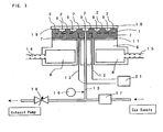
- a flow passage is formed to supply or diffuse heat generated in the process or heat to be supplied to an insulative substrate by a medium, and a gas supply conduit for supplying a gas which is enclosed within a space defined between the insulative substrate and the attracting surface of a dielectric for adjusting heat transmission therebetween, wherein the pressure of the enclosed gas can be adjusted by the temperature of the insulative substrate and thereby the temperature can be adjusted to a predetermined value.
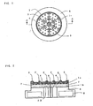
- FIG. 1 is a plane view showing ao example of an electrostatic chuck according to the present invention and FIG. 2 is a cross-sectional view thereof.
- FIG. 3 is a cross-sectional view showing the condition of attracting an insulative substrate 10 by an electrostatic chuck 1.
- an attracting force is generated between the insulative substrate 10 and the electrostatic chuck 1, thereby attracting the insulative substrate 10 at protrusions 2 and an outer peripheral seal ring 3 (hereinafter, collectively referred to as a "solid-body contact portion").
- the electrostatic chuck 1 is connected through a connector portion 11 onto a metal plate 6, and heating/cooling is conducted to the electrostatic chuck 1 by passing a medium through a medium flow passage 8 which is provided within the metal plate 6.
- FIGS. 4 through 6 show various examples of a pattern of the electrodes 7 which are formed on one surface of the dielectric.
- radio-frequency current which is used in a plasma process for SOS or SOI wafers can be dispersed into each of the electrodes, thereby enabling to reduce a load for each of electrically conductive terminals or the like.
- Gas is supplied through a gas supply conduit 13 from a gas supply opening 5 and enclosed within a gas enclosure portion 9.
- grooves 4 are formed on the surface of the electrostatic chuck 1.
- heat transmission is conducted between the insulative substrate 10 and the electrostatic chuck 1.
- a pressure control valve 17 is provided, and opened and closed by comparing the signal voltage of the gas pressure gauge 16 with a preset value, thereby enabling to adjust the pressure of the gas to the preset value.
- the electrostatically attracting force will correspond to the tensile strength of 300g/cm 2 in the case where the measured value is 300g/5cm 2 .
- This value corresponds to about 30 kPa, which is enough to attract the material to be attracted within a vacuum chamber.
- it was set to be 1 mm in the width of the electrode, 1 mm in the distance between the electrodes, and 0.5 mm in the thickness of the dielectric.
- 1A through 1D and 2 show the electrostatically attracting force in a case of varying the resistivity of the dielectric substrate.
- the resistivity does not have an influence to the electrostatic force very much; however, it is preferable that the resistivity be less than or equal to 10 13 ⁇ cm, which creates larger electrostatically attracting force.
- 1F and 1G show the electrostatically attracting force in a case of varying the surface roughness of the dielectric substrate.
- the surface roughness is less than or equal to Ra 0.25 ⁇ m.
- the surface rughness of the material to be attracted used in the present embodiment is less than or equal to Ra 0.1 ⁇ m, except for the substrate of polycrystal alumina in IP (which is not an embodiment of the present invention).
- 1B and 2 through 6 show the electrostatically attracting force in a case of varying the dielectric material.
- the resistivity rather than the relative dielectric constant has a larger relationship to the electrostatically attracting force.
- the most stable and large attracting force can be achieved by using ceramic sintered body obtained by adding chromium oxide and/or titanium oxide to alumina, and the material obtained by adding a sinter assisting material thereto.
- a substrate of polycrystal alumina is used as a material to be attracted, the surface roughness thereof is varied, and then the electrostatically attracting force is measured.
- the result shows that the sufficient force can be obtained if the surface roughness of the material to be attracted is around Ra 0.4 ⁇ m Therefore, when the relative dielectric constant of the material to be attracted becomes large, the surface roughness of the material to be attracted can be degraded.
- Table 2 shows the relationship between the electrostatically attracting force with respect to a glass substrate and the applied voltage (10 kV) in a case of using ceramic sintered body obtained by adding chromium oxide and/or titanium oxide to alumina, and varying the pattern of the electrodes in the electrostatic chuck.
- the maximum electrostatically attracting force can be obtained when the thickness of the dielectric is 0.3 mm, and there is a tendency that the thinner the thickness thereof, the larger the electrostatically attracting force.
- both of the width and the distance are equal to or greater than 0.5 mm, the electrostatically attracting is available.
- sufficient insulation between the electrodes cannot be achieved if the distance between the electrodes is smaller than 0.5 mm. As a result of this, there are cases where the electrostatically attracting cannot be obtained.
- the electrostatically attracting force can hardly be obtained.
- the voltage applied is raised to 10 kV. It is expected that the sufficient force can be obtained even if the distance between the electrodes is 2 mm, by applying voltage being larger than that.
- the thickness of the dielectric in the range of 0.3 to 2.0 mm, the distance between the electrodes in the range of 0.5 to 1.0 mm, the width of the electrode in the range of 0.5 to 4.0 mm, and the resistivity of the dielectric to be less than or equal to 10 13 ⁇ cm. It is more preferable that the thickness of the dielectric be in the range of 0.3 to 1.0 mm, the distance between the electrodes in the range of 0.5 to 1.0 mm, the width of the electrode in the range of 0.5 to 1.0 mm, and the resistivity of the dielectric to be less than or equal to 10 13 ⁇ cm.
- FIGS. 7 through 9 are graphs showing data on thermal attraction experiments and cooling experiments on an insulative substrate.
- a glass substrate i.e., a low alkaline glass, which is outside the scope of the present invention but remains for illustrative purposes
- the insulative substrates 10 are used as the insulative substrates 10.
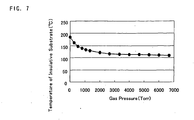
- FIG. 7 is a graph showing the relationship between the temperature of an insulative substrate and the pressure of the gas for heating/cooling to be supplied into a space between the insulative substrate and the attracting surface of the dielectric, in which the insulative substrate is positioned in a substrate heating/cooling apparatus which is provided within a vacuum chamber.
- the thermal characteristic in a case where a heat flow of 2W/cm 2 is supplied from the upper surface of the insulative substrate 10 is shown by expressing the pressure of the above-mentioned gas on x-axis and the surface temperature of the insulative substrate 10 on y-axis.
- This graph shows that the temperature of the insulative substrate 10 can be controlled by varying the gas pressure enclosed in a gas enclosure portion 9. He gas is mainly used in the present experiment; however, the same heating/cooling effect can be obtained by using Ar or N 2 .
- the height of the protrusions 2 In order to increase efficiency of the heating/cooling by supplying higher pressure, it is necessary to make the height of the protrusions 2 on the attracting surface of the dielectric 19 low and thereby bring the pressure of the gas into the region of a molecular flow.
- the height of the protrusions 2 may be set to be less than or equal to 5 ⁇ m.
- the formation of the grooves 4 is important as well as the protrusions 2.
- the effect can be achieved when they are formed in a radial pattern from the gas supply opening, and they are equal to or greater than 1.0 mm in the width and equal to or greater than 50 ⁇ m in the depth.
- the width is equal to or greater than 1.5 mm and the depth is equal to or greater than 250 ⁇ m, and thereby the time until the pressure distribution in the shape comes to be uniform is less than or equal to 5 seconds.
- the effect can be further increased if the grooves are formed in a concentric pattern as well as a radial pattern.
- the experiment result shows that the temperature of the insulative substrate 10 is varied by varying the ratio of a contact area.
- the contact area ratio it is necessary to vary the number and the diameter of the protrusions.
- the diameter of the protrusions in the present embodiment is 5 mm, and the width of the seal ring is 4 mm.
- the number of the protrusions is converted from the contract area ratio.
- the protrusions are distributed upon the surface of the electrostatic chuck in the substantially equal position with regards to each other.
- the example shows that large heating/cooling effect on the insulative substrate 10 can be obtained by enclosing the high gas pressure of 6664 Pa (50 Torr) in the gas enclosure portion 9.
- the electrostatic chuck generate a large attracting force.
- the gas pressure of 1333 Pa (10 Torr) in a case where the contact area ratio is 20 % theoretically, the attracting force of at least 13 g/cm 2 is required. Therefore, the electrostatic chuck having a very large attracting force is required.
- Ceramic sintered body comprised of mainly alumina, and chromium oxide (Cr 2 O 3 ), titanium oxide (TiO 2 ), and a sinter assisting material added thereto in an appropriate amount.
- the attracting force in this material is about 300 g/5cm 2 under application of 10 KV, which is the same as 1A - 1C mentioned above, and the tensile strength in the vertical direction can be assumed to be 300 g/cm 2 Even if the contact area ratio is 20%, it can be ensured that the attracting force is equal to or greater than 60 g/cm 2 . Therefore, it is possible to sufficiently attract the insulative substrate which in the present invention is an SOS or SOI wafer.
- the signal outputted from the measurement apparatus is compared with a predetermined value, and thereby the temperature of the material to be attracted can easily be controlled.
- the temperature of the insulative substrate cannot directly be measured, it is possible to maintain the temperature of the insulative substrate based on a data base in which the gas pressure, the applied voltage, the ratio of the solid-body contact area, the supplied thermal energy, the flow rate of the medium, the temperature of the medium, or the like are compiled in advance and linked together.
- the heating/cooling apparatus for an insulative substrate according to the present embodiment within a reaction chamber, it is possible to easily control the temperature in a semiconductor manufacturing process, in particular, in a plasma CVD for an SOS or SOI, a plasma etching, a sputtering, or the like.
- a material to be processed can be attracted with the electrostatic chuck even if it is an insulative material, it is possible to easily heat/cool the insulative substate with the heating/cooling apparatus in which the electrostatic chuck is installed, and thereby it is possible to control the temperature of the insulative substrate at a predetermined value.
Landscapes
- Engineering & Computer Science (AREA)
- Mechanical Engineering (AREA)
- Physics & Mathematics (AREA)
- Condensed Matter Physics & Semiconductors (AREA)
- General Physics & Mathematics (AREA)
- Manufacturing & Machinery (AREA)
- Computer Hardware Design (AREA)
- Microelectronics & Electronic Packaging (AREA)
- Power Engineering (AREA)
- Container, Conveyance, Adherence, Positioning, Of Wafer (AREA)
- Jigs For Machine Tools (AREA)
Applications Claiming Priority (2)
| Application Number | Priority Date | Filing Date | Title |
|---|---|---|---|
| JP14550799A JP3805134B2 (ja) | 1999-05-25 | 1999-05-25 | 絶縁性基板吸着用静電チャック |
| EP00929866A EP1191581B1 (en) | 1999-05-25 | 2000-05-25 | Method for Electrostatically Attracting and Processing a Glass Insulative Substrate |
Related Parent Applications (2)
| Application Number | Title | Priority Date | Filing Date |
|---|---|---|---|
| EP00929866.2 Division | 2000-05-25 | ||
| EP00929866A Division EP1191581B1 (en) | 1999-05-25 | 2000-05-25 | Method for Electrostatically Attracting and Processing a Glass Insulative Substrate |
Publications (2)
| Publication Number | Publication Date |
|---|---|
| EP1852907A1 EP1852907A1 (en) | 2007-11-07 |
| EP1852907B1 true EP1852907B1 (en) | 2013-07-03 |
Family
ID=15386861
Family Applications (2)
| Application Number | Title | Priority Date | Filing Date |
|---|---|---|---|
| EP07013291.5A Expired - Lifetime EP1852907B1 (en) | 1999-05-25 | 2000-05-25 | Method for holding and processing SOS or SOI wafers |
| EP00929866A Expired - Lifetime EP1191581B1 (en) | 1999-05-25 | 2000-05-25 | Method for Electrostatically Attracting and Processing a Glass Insulative Substrate |
Family Applications After (1)
| Application Number | Title | Priority Date | Filing Date |
|---|---|---|---|
| EP00929866A Expired - Lifetime EP1191581B1 (en) | 1999-05-25 | 2000-05-25 | Method for Electrostatically Attracting and Processing a Glass Insulative Substrate |
Country Status (9)
| Country | Link |
|---|---|
| US (2) | US6768627B1 (enExample) |
| EP (2) | EP1852907B1 (enExample) |
| JP (1) | JP3805134B2 (enExample) |
| KR (4) | KR20020019030A (enExample) |
| CN (3) | CN1595631A (enExample) |
| AU (1) | AU4781300A (enExample) |
| DE (1) | DE60037885T2 (enExample) |
| TW (1) | TW508716B (enExample) |
| WO (1) | WO2000072376A1 (enExample) |
Families Citing this family (127)
| Publication number | Priority date | Publication date | Assignee | Title |
|---|---|---|---|---|
| JP2001035907A (ja) | 1999-07-26 | 2001-02-09 | Ulvac Japan Ltd | 吸着装置 |
| TWI254403B (en) * | 2000-05-19 | 2006-05-01 | Ngk Insulators Ltd | Electrostatic clamper, and electrostatic attracting structures |
| JP4697833B2 (ja) * | 2000-06-14 | 2011-06-08 | キヤノンアネルバ株式会社 | 静電吸着機構及び表面処理装置 |
| JP3693895B2 (ja) * | 2000-07-24 | 2005-09-14 | 住友大阪セメント株式会社 | 可撓性フィルムの静電吸着装置、可撓性フィルムの静電吸着方法、可撓性フィルムの表面処理方法 |
| JP4156788B2 (ja) * | 2000-10-23 | 2008-09-24 | 日本碍子株式会社 | 半導体製造装置用サセプター |
| JP4548928B2 (ja) * | 2000-10-31 | 2010-09-22 | 京セラ株式会社 | 電極内蔵体及びこれを用いたウエハ支持部材 |
| KR100750835B1 (ko) * | 2001-01-19 | 2007-08-22 | 가부시키가이샤 알박 | 흡착장치 |
| KR20020064507A (ko) * | 2001-02-02 | 2002-08-09 | 삼성전자 주식회사 | 정전 척과 그의 제조방법 |
| KR20020064508A (ko) * | 2001-02-02 | 2002-08-09 | 삼성전자 주식회사 | 정전 척 |
| JP2005033221A (ja) * | 2001-02-08 | 2005-02-03 | Tokyo Electron Ltd | 基板載置台および処理装置 |
| JP2002270681A (ja) * | 2001-03-07 | 2002-09-20 | Anelva Corp | 基板処理用静電吸着機構 |
| JP4503196B2 (ja) * | 2001-03-07 | 2010-07-14 | 株式会社アルバック | 封着室、パネル保持台及び封着方法 |
| JP3408530B2 (ja) | 2001-04-26 | 2003-05-19 | 東京エレクトロン株式会社 | 半導体製造装置用部材およびその製造方法 |
| US6805968B2 (en) | 2001-04-26 | 2004-10-19 | Tocalo Co., Ltd. | Members for semiconductor manufacturing apparatus and method for producing the same |
| JP2002345273A (ja) * | 2001-05-18 | 2002-11-29 | Toto Ltd | 静電チャック |
| JP2003077994A (ja) * | 2001-08-30 | 2003-03-14 | Kyocera Corp | 静電チャック及びその製造方法 |
| JP4094262B2 (ja) * | 2001-09-13 | 2008-06-04 | 住友大阪セメント株式会社 | 吸着固定装置及びその製造方法 |
| WO2003092064A1 (en) * | 2002-04-25 | 2003-11-06 | Tokyo Electron Limited | Member for semiconductor manufacturing system and its manufacturing method |
| US6660665B2 (en) * | 2002-05-01 | 2003-12-09 | Japan Fine Ceramics Center | Platen for electrostatic wafer clamping apparatus |
| EP1359469B1 (en) * | 2002-05-01 | 2011-03-02 | ASML Netherlands B.V. | Chuck, lithographic projection apparatus and device manufacturing method |
| EP1359466A1 (en) * | 2002-05-01 | 2003-11-05 | ASML Netherlands B.V. | Chuck, lithographic projection apparatus, method of manufacturing a chuck and device manufacturing method |
| KR100511854B1 (ko) | 2002-06-18 | 2005-09-02 | 아네르바 가부시키가이샤 | 정전 흡착 장치 |
| US7255775B2 (en) | 2002-06-28 | 2007-08-14 | Toshiba Ceramics Co., Ltd. | Semiconductor wafer treatment member |
| JP2004228456A (ja) * | 2003-01-27 | 2004-08-12 | Canon Inc | 露光装置 |
| US7033443B2 (en) * | 2003-03-28 | 2006-04-25 | Axcelis Technologies, Inc. | Gas-cooled clamp for RTP |
| US20050042881A1 (en) * | 2003-05-12 | 2005-02-24 | Tokyo Electron Limited | Processing apparatus |
| JP3748559B2 (ja) * | 2003-06-30 | 2006-02-22 | キヤノン株式会社 | ステージ装置、露光装置、荷電ビーム描画装置、デバイス製造方法、基板電位測定方法及び静電チャック |
| EP1498777A1 (en) * | 2003-07-15 | 2005-01-19 | ASML Netherlands B.V. | Substrate holder and lithographic projection apparatus |
| US7072165B2 (en) * | 2003-08-18 | 2006-07-04 | Axcelis Technologies, Inc. | MEMS based multi-polar electrostatic chuck |
| US6947274B2 (en) * | 2003-09-08 | 2005-09-20 | Axcelis Technologies, Inc. | Clamping and de-clamping semiconductor wafers on an electrostatic chuck using wafer inertial confinement by applying a single-phase square wave AC clamping voltage |
| US7072166B2 (en) * | 2003-09-12 | 2006-07-04 | Axcelis Technologies, Inc. | Clamping and de-clamping semiconductor wafers on a J-R electrostatic chuck having a micromachined surface by using force delay in applying a single-phase square wave AC clamping voltage |
| US6905984B2 (en) * | 2003-10-10 | 2005-06-14 | Axcelis Technologies, Inc. | MEMS based contact conductivity electrostatic chuck |
| US6946403B2 (en) * | 2003-10-28 | 2005-09-20 | Axcelis Technologies, Inc. | Method of making a MEMS electrostatic chuck |
| KR100666039B1 (ko) | 2003-12-05 | 2007-01-10 | 동경 엘렉트론 주식회사 | 정전척 |
| JP4636807B2 (ja) * | 2004-03-18 | 2011-02-23 | キヤノン株式会社 | 基板保持装置およびそれを用いた露光装置 |
| JP4684222B2 (ja) * | 2004-03-19 | 2011-05-18 | 株式会社クリエイティブ テクノロジー | 双極型静電チャック |
| US7595972B2 (en) * | 2004-04-09 | 2009-09-29 | Varian Semiconductor Equipment Associates, Inc. | Clamp for use in processing semiconductor workpieces |
| KR101064872B1 (ko) * | 2004-06-30 | 2011-09-16 | 주성엔지니어링(주) | 정전척 |
| US7544251B2 (en) | 2004-10-07 | 2009-06-09 | Applied Materials, Inc. | Method and apparatus for controlling temperature of a substrate |
| JP2008027927A (ja) * | 2004-10-29 | 2008-02-07 | Shin-Etsu Engineering Co Ltd | 真空貼り合わせ装置用静電チャック |
| CN100382275C (zh) * | 2004-10-29 | 2008-04-16 | 东京毅力科创株式会社 | 基板载置台、基板处理装置及基板的温度控制方法 |
| TWI271815B (en) * | 2004-11-30 | 2007-01-21 | Sanyo Electric Co | Method for processing stuck object and electrostatic sticking method |
| JP2006332204A (ja) * | 2005-05-24 | 2006-12-07 | Toto Ltd | 静電チャック |
| JP4783213B2 (ja) * | 2005-06-09 | 2011-09-28 | 日本碍子株式会社 | 静電チャック |
| US20070139855A1 (en) | 2005-12-21 | 2007-06-21 | Asml Netherlands B.V. | Lithographic apparatus and method of manufacturing an electrostatic clamp for a lithographic apparatus |
| US7646581B2 (en) * | 2006-01-31 | 2010-01-12 | Sumitomo Osaka Cement Co., Ltd. | Electrostatic chuck |
| JP4707593B2 (ja) * | 2006-03-23 | 2011-06-22 | 大日本スクリーン製造株式会社 | 熱処理装置と基板吸着方法 |
| JP4808149B2 (ja) * | 2006-03-29 | 2011-11-02 | 新光電気工業株式会社 | 静電チャック |
| JP5069452B2 (ja) * | 2006-04-27 | 2012-11-07 | アプライド マテリアルズ インコーポレイテッド | 二重温度帯を有する静電チャックをもつ基板支持体 |
| US8226769B2 (en) | 2006-04-27 | 2012-07-24 | Applied Materials, Inc. | Substrate support with electrostatic chuck having dual temperature zones |
| WO2008082977A2 (en) * | 2006-12-26 | 2008-07-10 | Saint-Gobain Ceramics & Plastics, Inc. | Electrostatic chuck and method of forming |
| US7983017B2 (en) | 2006-12-26 | 2011-07-19 | Saint-Gobain Ceramics & Plastics, Inc. | Electrostatic chuck and method of forming |
| US7385799B1 (en) * | 2007-02-07 | 2008-06-10 | Axcelis Technology, Inc. | Offset phase operation on a multiphase AC electrostatic clamp |
| KR101402880B1 (ko) * | 2007-02-16 | 2014-06-03 | 엘아이지에이디피 주식회사 | 나뭇가지 형상의 전극 패턴을 가지는 바이폴라 정전척 및이를 이용한 기판 처리 방법 |
| US20080259236A1 (en) * | 2007-04-13 | 2008-10-23 | Saint-Gobain Ceramics & Plastics, Inc. | Electrostatic dissipative stage and effectors for use in forming lcd products |
| TW200912051A (en) * | 2007-04-16 | 2009-03-16 | Saint Gobain Ceramics & Amp Plastics Inc | Process of cleaning a substrate for microelectronic applications including directing mechanical energy through a fluid bath and apparatus of same |
| JP4976911B2 (ja) * | 2007-04-27 | 2012-07-18 | 新光電気工業株式会社 | 静電チャック |
| US7667944B2 (en) * | 2007-06-29 | 2010-02-23 | Praxair Technology, Inc. | Polyceramic e-chuck |
| WO2009019749A1 (ja) * | 2007-08-03 | 2009-02-12 | Teoss Co., Ltd. | シリコン支持装置およびこれを用いたシリコン加熱急冷装置 |
| TWI475594B (zh) | 2008-05-19 | 2015-03-01 | Entegris Inc | 靜電夾頭 |
| JP5049891B2 (ja) | 2008-06-13 | 2012-10-17 | 新光電気工業株式会社 | 基板温調固定装置 |
| JP5025576B2 (ja) | 2008-06-13 | 2012-09-12 | 新光電気工業株式会社 | 静電チャック及び基板温調固定装置 |
| JP2011530833A (ja) * | 2008-08-12 | 2011-12-22 | アプライド マテリアルズ インコーポレイテッド | 静電チャックアセンブリ |
| JP4611409B2 (ja) * | 2008-09-03 | 2011-01-12 | 晃俊 沖野 | プラズマ温度制御装置 |
| US8139340B2 (en) * | 2009-01-20 | 2012-03-20 | Plasma-Therm Llc | Conductive seal ring electrostatic chuck |
| US8861170B2 (en) | 2009-05-15 | 2014-10-14 | Entegris, Inc. | Electrostatic chuck with photo-patternable soft protrusion contact surface |
| SG176059A1 (en) | 2009-05-15 | 2011-12-29 | Entegris Inc | Electrostatic chuck with polymer protrusions |
| US8817449B2 (en) * | 2010-03-26 | 2014-08-26 | Ulvac, Inc. | Substrate holding device |
| KR101134736B1 (ko) * | 2010-04-26 | 2012-04-13 | 가부시키가이샤 크리에이티브 테크놀러지 | 스페이서를 구비하는 정전 척 및 그 제조방법 |
| WO2011149918A2 (en) * | 2010-05-28 | 2011-12-01 | Entegris, Inc. | High surface resistivity electrostatic chuck |
| JP5454803B2 (ja) * | 2010-08-11 | 2014-03-26 | Toto株式会社 | 静電チャック |
| CN102487029B (zh) * | 2010-12-02 | 2014-03-19 | 北京北方微电子基地设备工艺研究中心有限责任公司 | 静电卡盘和具有它的等离子体装置 |
| US9105705B2 (en) * | 2011-03-14 | 2015-08-11 | Plasma-Therm Llc | Method and apparatus for plasma dicing a semi-conductor wafer |
| US9869392B2 (en) | 2011-10-20 | 2018-01-16 | Lam Research Corporation | Edge seal for lower electrode assembly |
| US9859142B2 (en) | 2011-10-20 | 2018-01-02 | Lam Research Corporation | Edge seal for lower electrode assembly |
| JP5993568B2 (ja) * | 2011-11-09 | 2016-09-14 | 東京エレクトロン株式会社 | 基板載置システム、基板処理装置、静電チャック及び基板冷却方法 |
| US8902561B2 (en) * | 2012-02-02 | 2014-12-02 | Taiwan Semiconductor Manufacturing Co., Ltd. | Electrostatic chuck with multi-zone control |
| US9276504B2 (en) * | 2012-03-07 | 2016-03-01 | Ngk Spark Plug Co., Ltd. | Carrier device and ceramic member |
| US9030797B2 (en) * | 2012-06-01 | 2015-05-12 | Infineon Technologies Ag | Thin substrate electrostatic chuck system and method |
| JP5975755B2 (ja) | 2012-06-28 | 2016-08-23 | 株式会社日立ハイテクノロジーズ | プラズマ処理装置およびプラズマ処理方法 |
| KR102032744B1 (ko) * | 2012-09-05 | 2019-11-11 | 삼성디스플레이 주식회사 | 기판 고정장치 및 이의 제조방법 |
| JP6016946B2 (ja) * | 2012-12-20 | 2016-10-26 | キヤノンアネルバ株式会社 | 酸化処理装置、酸化方法、および電子デバイスの製造方法 |
| JP6526575B2 (ja) * | 2013-02-07 | 2019-06-05 | エーエスエムエル ホールディング エヌ.ブイ. | リソグラフィ装置及び方法 |
| KR101986266B1 (ko) * | 2013-03-29 | 2019-06-07 | 스미토모 오사카 세멘토 가부시키가이샤 | 정전 척 장치 |
| JP5633766B2 (ja) * | 2013-03-29 | 2014-12-03 | Toto株式会社 | 静電チャック |
| CN104124127A (zh) * | 2013-04-27 | 2014-10-29 | 北京北方微电子基地设备工艺研究中心有限责任公司 | 托盘及等离子体加工设备 |
| WO2015013142A1 (en) | 2013-07-22 | 2015-01-29 | Applied Materials, Inc. | An electrostatic chuck for high temperature process applications |
| KR101812666B1 (ko) * | 2013-08-05 | 2017-12-27 | 어플라이드 머티어리얼스, 인코포레이티드 | 얇은 기판 취급을 위한 정전 캐리어 |
| KR101876501B1 (ko) | 2013-08-05 | 2018-07-10 | 어플라이드 머티어리얼스, 인코포레이티드 | 인-시츄 제거 가능한 정전 척 |
| KR20180110213A (ko) | 2013-08-06 | 2018-10-08 | 어플라이드 머티어리얼스, 인코포레이티드 | 국부적으로 가열되는 다-구역 기판 지지부 |
| US10304713B2 (en) | 2013-09-20 | 2019-05-28 | Applied Materials, Inc. | Substrate carrier with integrated electrostatic chuck |
| US9460950B2 (en) | 2013-12-06 | 2016-10-04 | Applied Materials, Inc. | Wafer carrier for smaller wafers and wafer pieces |
| US9101038B2 (en) | 2013-12-20 | 2015-08-04 | Lam Research Corporation | Electrostatic chuck including declamping electrode and method of declamping |
| US10090211B2 (en) | 2013-12-26 | 2018-10-02 | Lam Research Corporation | Edge seal for lower electrode assembly |
| JP6219178B2 (ja) * | 2014-01-20 | 2017-10-25 | 株式会社ディスコ | プラズマエッチング装置 |
| CN106165141B (zh) | 2014-05-09 | 2019-01-15 | 应用材料公司 | 基板载体系统及使用它的方法 |
| KR20170002603A (ko) | 2014-05-09 | 2017-01-06 | 어플라이드 머티어리얼스, 인코포레이티드 | 보호 커버링을 갖는 기판 캐리어 시스템 |
| US10832931B2 (en) | 2014-05-30 | 2020-11-10 | Applied Materials, Inc. | Electrostatic chuck with embossed top plate and cooling channels |
| US9959961B2 (en) | 2014-06-02 | 2018-05-01 | Applied Materials, Inc. | Permanent magnetic chuck for OLED mask chucking |
| US10002782B2 (en) | 2014-10-17 | 2018-06-19 | Lam Research Corporation | ESC assembly including an electrically conductive gasket for uniform RF power delivery therethrough |
| CN104400298B (zh) * | 2014-12-15 | 2017-01-25 | 天津科信磁性机械有限公司 | 水冷式磁力模块及其操作方法 |
| US20160230269A1 (en) * | 2015-02-06 | 2016-08-11 | Applied Materials, Inc. | Radially outward pad design for electrostatic chuck surface |
| US10332773B2 (en) | 2015-06-04 | 2019-06-25 | Applied Materials, Inc. | Transparent electrostatic carrier |
| JP6510461B2 (ja) * | 2016-05-25 | 2019-05-08 | 日本特殊陶業株式会社 | 基板保持装置 |
| US10832936B2 (en) * | 2016-07-27 | 2020-11-10 | Lam Research Corporation | Substrate support with increasing areal density and corresponding method of fabricating |
| US20180148835A1 (en) * | 2016-11-29 | 2018-05-31 | Lam Research Corporation | Substrate support with varying depths of areas between mesas and corresponding temperature dependent method of fabricating |
| KR101871067B1 (ko) * | 2016-11-30 | 2018-06-25 | 세메스 주식회사 | 기판을 지지하는 척 모듈 및 이를 구비하는 프로브 스테이션 |
| US11955362B2 (en) * | 2017-09-13 | 2024-04-09 | Applied Materials, Inc. | Substrate support for reduced damage substrate backside |
| US10497667B2 (en) | 2017-09-26 | 2019-12-03 | Taiwan Semiconductor Manufacturing Co., Ltd. | Apparatus for bond wave propagation control |
| WO2019187785A1 (ja) * | 2018-03-26 | 2019-10-03 | 日本碍子株式会社 | 静電チャックヒータ |
| KR102427823B1 (ko) * | 2018-06-11 | 2022-07-29 | 캐논 톡키 가부시키가이샤 | 정전척 시스템, 성막장치, 흡착방법, 성막방법 및 전자 디바이스의 제조방법 |
| CN108673211B (zh) * | 2018-07-27 | 2020-07-14 | 上海理工大学 | 一种装夹装置及使用方法 |
| JP7145042B2 (ja) * | 2018-11-08 | 2022-09-30 | 東京エレクトロン株式会社 | 基板支持器及びプラズマ処理装置 |
| US11031273B2 (en) | 2018-12-07 | 2021-06-08 | Applied Materials, Inc. | Physical vapor deposition (PVD) electrostatic chuck with improved thermal coupling for temperature sensitive processes |
| CN109449907B (zh) * | 2018-12-11 | 2024-01-12 | 广东海拓创新技术有限公司 | 一种透明静电吸盘及其制备方法 |
| TWI748304B (zh) * | 2018-12-21 | 2021-12-01 | 日商Toto股份有限公司 | 靜電吸盤 |
| CN109881184B (zh) * | 2019-03-29 | 2022-03-25 | 拓荆科技股份有限公司 | 具有静电力抑制的基板承载装置 |
| KR102573002B1 (ko) * | 2019-06-28 | 2023-08-30 | 엔지케이 인슐레이터 엘티디 | 정전 척 |
| JP7316181B2 (ja) * | 2019-10-11 | 2023-07-27 | 日本特殊陶業株式会社 | 静電チャック |
| JP7370228B2 (ja) * | 2019-11-22 | 2023-10-27 | 東京エレクトロン株式会社 | プラズマ処理装置 |
| JP7580191B2 (ja) * | 2019-11-29 | 2024-11-11 | 日本特殊陶業株式会社 | 静電チャック |
| CN112234015B (zh) * | 2020-10-12 | 2022-05-13 | 烟台睿瓷新材料技术有限公司 | 一种同心圆结构的静电吸盘电极图形结构 |
| CN114664723A (zh) * | 2020-12-23 | 2022-06-24 | 北京华卓精科科技股份有限公司 | 静电卡盘及其制造方法 |
| TWI804819B (zh) * | 2021-02-23 | 2023-06-11 | 台灣積體電路製造股份有限公司 | 移除微粒的方法 |
| CN113903699A (zh) * | 2021-09-22 | 2022-01-07 | 北京北方华创微电子装备有限公司 | 静电卡盘及半导体加工设备 |
| KR102654902B1 (ko) * | 2021-10-27 | 2024-04-29 | 피에스케이 주식회사 | 지지 유닛 및 이를 포함하는 기판 처리 장치 |
| TWI891529B (zh) * | 2024-10-08 | 2025-07-21 | 億鴻工業股份有限公司 | 玻璃基板電鍍夾具 |
Family Cites Families (33)
| Publication number | Priority date | Publication date | Assignee | Title |
|---|---|---|---|---|
| JPS6059104B2 (ja) * | 1982-02-03 | 1985-12-23 | 株式会社東芝 | 静電チヤツク板 |
| JP2665242B2 (ja) * | 1988-09-19 | 1997-10-22 | 東陶機器株式会社 | 静電チャック |
| US4962441A (en) | 1989-04-10 | 1990-10-09 | Applied Materials, Inc. | Isolated electrostatic wafer blade clamp |
| JPH03145151A (ja) * | 1989-10-31 | 1991-06-20 | Toshiba Corp | 静電チャック装置 |
| JPH06737A (ja) * | 1991-03-29 | 1994-01-11 | Shin Etsu Chem Co Ltd | 静電チャック基板 |
| US5191506A (en) * | 1991-05-02 | 1993-03-02 | International Business Machines Corporation | Ceramic electrostatic chuck |
| JPH0563062A (ja) | 1991-08-30 | 1993-03-12 | Toto Ltd | 静電チヤツク |
| JP3084869B2 (ja) * | 1991-12-10 | 2000-09-04 | 東陶機器株式会社 | 静電チャック |
| US5684669A (en) * | 1995-06-07 | 1997-11-04 | Applied Materials, Inc. | Method for dechucking a workpiece from an electrostatic chuck |
| US5460684A (en) * | 1992-12-04 | 1995-10-24 | Tokyo Electron Limited | Stage having electrostatic chuck and plasma processing apparatus using same |
| US5384681A (en) * | 1993-03-01 | 1995-01-24 | Toto Ltd. | Electrostatic chuck |
| EP0635870A1 (en) * | 1993-07-20 | 1995-01-25 | Applied Materials, Inc. | An electrostatic chuck having a grooved surface |
| US5463526A (en) * | 1994-01-21 | 1995-10-31 | Lam Research Corporation | Hybrid electrostatic chuck |
| US5646814A (en) * | 1994-07-15 | 1997-07-08 | Applied Materials, Inc. | Multi-electrode electrostatic chuck |
| US5671116A (en) * | 1995-03-10 | 1997-09-23 | Lam Research Corporation | Multilayered electrostatic chuck and method of manufacture thereof |
| KR100214438B1 (ko) * | 1995-03-17 | 1999-08-02 | 히가시 데쓰로 | 스테이지 장치 |
| US5886863A (en) * | 1995-05-09 | 1999-03-23 | Kyocera Corporation | Wafer support member |
| JPH0917770A (ja) * | 1995-06-28 | 1997-01-17 | Sony Corp | プラズマ処理方法およびこれに用いるプラズマ装置 |
| US5847918A (en) * | 1995-09-29 | 1998-12-08 | Lam Research Corporation | Electrostatic clamping method and apparatus for dielectric workpieces in vacuum processors |
| US5838529A (en) | 1995-12-22 | 1998-11-17 | Lam Research Corporation | Low voltage electrostatic clamp for substrates such as dielectric substrates |
| JPH09213777A (ja) * | 1996-01-31 | 1997-08-15 | Kyocera Corp | 静電チャック |
| US5810933A (en) * | 1996-02-16 | 1998-09-22 | Novellus Systems, Inc. | Wafer cooling device |
| US5761023A (en) * | 1996-04-25 | 1998-06-02 | Applied Materials, Inc. | Substrate support with pressure zones having reduced contact area and temperature feedback |
| US5745332A (en) * | 1996-05-08 | 1998-04-28 | Applied Materials, Inc. | Monopolar electrostatic chuck having an electrode in contact with a workpiece |
| CN1178392A (zh) * | 1996-09-19 | 1998-04-08 | 株式会社日立制作所 | 静电吸盘和应用了静电吸盘的样品处理方法及装置 |
| US5958813A (en) * | 1996-11-26 | 1999-09-28 | Kyocera Corporation | Semi-insulating aluminum nitride sintered body |
| JP3527823B2 (ja) | 1997-01-31 | 2004-05-17 | 京セラ株式会社 | 静電チャック |
| JPH10242256A (ja) * | 1997-02-26 | 1998-09-11 | Kyocera Corp | 静電チャック |
| JPH118291A (ja) * | 1997-06-18 | 1999-01-12 | Hitachi Ltd | 静電吸着装置 |
| JP3623107B2 (ja) * | 1997-07-31 | 2005-02-23 | 京セラ株式会社 | 静電チャック |
| WO1999025007A1 (en) * | 1997-11-06 | 1999-05-20 | Applied Materials, Inc. | Multi-electrode electrostatic chuck having fuses in hollow cavities |
| JPH11163109A (ja) * | 1997-12-01 | 1999-06-18 | Kyocera Corp | ウエハ保持装置 |
| JP2000323558A (ja) * | 1999-05-07 | 2000-11-24 | Nikon Corp | 静電吸着装置 |
-
1999
- 1999-05-25 JP JP14550799A patent/JP3805134B2/ja not_active Expired - Lifetime
-
2000
- 2000-05-24 TW TW089110073A patent/TW508716B/zh not_active IP Right Cessation
- 2000-05-25 DE DE60037885T patent/DE60037885T2/de not_active Expired - Lifetime
- 2000-05-25 EP EP07013291.5A patent/EP1852907B1/en not_active Expired - Lifetime
- 2000-05-25 KR KR1020017015040A patent/KR20020019030A/ko not_active Ceased
- 2000-05-25 US US09/979,627 patent/US6768627B1/en not_active Expired - Lifetime
- 2000-05-25 CN CNA2004100855627A patent/CN1595631A/zh active Pending
- 2000-05-25 KR KR1020077009029A patent/KR100933727B1/ko not_active Expired - Lifetime
- 2000-05-25 AU AU47813/00A patent/AU4781300A/en not_active Abandoned
- 2000-05-25 CN CNB008108846A patent/CN1179407C/zh not_active Expired - Fee Related
- 2000-05-25 KR KR1020087028422A patent/KR20090003347A/ko not_active Ceased
- 2000-05-25 CN CNB2004100855631A patent/CN100375263C/zh not_active Expired - Fee Related
- 2000-05-25 EP EP00929866A patent/EP1191581B1/en not_active Expired - Lifetime
- 2000-05-25 KR KR1020097016855A patent/KR20090100455A/ko not_active Ceased
- 2000-05-25 WO PCT/JP2000/003355 patent/WO2000072376A1/ja not_active Ceased
-
2004
- 2004-05-28 US US10/857,068 patent/US7209339B2/en not_active Expired - Lifetime
Also Published As
| Publication number | Publication date |
|---|---|
| US20040218340A1 (en) | 2004-11-04 |
| CN1595632A (zh) | 2005-03-16 |
| US6768627B1 (en) | 2004-07-27 |
| KR20070049689A (ko) | 2007-05-11 |
| KR20090003347A (ko) | 2009-01-09 |
| KR20090100455A (ko) | 2009-09-23 |
| EP1191581B1 (en) | 2008-01-23 |
| KR20020019030A (ko) | 2002-03-09 |
| KR100933727B1 (ko) | 2009-12-24 |
| DE60037885D1 (de) | 2008-03-13 |
| CN1179407C (zh) | 2004-12-08 |
| CN1365518A (zh) | 2002-08-21 |
| TW508716B (en) | 2002-11-01 |
| JP3805134B2 (ja) | 2006-08-02 |
| EP1191581A4 (en) | 2006-03-22 |
| AU4781300A (en) | 2000-12-12 |
| CN100375263C (zh) | 2008-03-12 |
| DE60037885T2 (de) | 2009-01-15 |
| US7209339B2 (en) | 2007-04-24 |
| WO2000072376A1 (en) | 2000-11-30 |
| JP2000332091A (ja) | 2000-11-30 |
| EP1191581A1 (en) | 2002-03-27 |
| CN1595631A (zh) | 2005-03-16 |
| EP1852907A1 (en) | 2007-11-07 |
Similar Documents
| Publication | Publication Date | Title |
|---|---|---|
| EP1852907B1 (en) | Method for holding and processing SOS or SOI wafers | |
| JP2000332091A5 (enExample) | ||
| US11302556B2 (en) | Apparatus for spatial and temporal control of temperature on a substrate | |
| US4384918A (en) | Method and apparatus for dry etching and electrostatic chucking device used therein | |
| US6781812B2 (en) | Chuck equipment | |
| EP1399964B1 (en) | Ceramic electrostatic chuck and its use | |
| US6022418A (en) | Vacuum processing method | |
| JP2000174106A (ja) | ワ―クピ―スを保持するための装置 | |
| US6949726B2 (en) | Heating apparatus having electrostatic adsorption function | |
| JP4837189B2 (ja) | 基板保持機構及び基板処理装置 | |
| JP2756944B2 (ja) | セラミックス静電チャック | |
| JP2006253703A (ja) | 静電チャック及び絶縁性基板静電吸着処理方法 | |
| JP2006157032A (ja) | 静電チャック、静電吸着方法、加熱冷却処理装置、静電吸着処理装置 | |
| JP2001217304A (ja) | 基板ステージ、それを用いた基板処理装置および基板処理方法 | |
| KR100750835B1 (ko) | 흡착장치 |
Legal Events
| Date | Code | Title | Description |
|---|---|---|---|
| PUAI | Public reference made under article 153(3) epc to a published international application that has entered the european phase |
Free format text: ORIGINAL CODE: 0009012 |
|
| AC | Divisional application: reference to earlier application |
Ref document number: 1191581 Country of ref document: EP Kind code of ref document: P |
|
| AK | Designated contracting states |
Kind code of ref document: A1 Designated state(s): DE FR GB |
|
| 17P | Request for examination filed |
Effective date: 20080507 |
|
| 17Q | First examination report despatched |
Effective date: 20080610 |
|
| AKX | Designation fees paid |
Designated state(s): DE FR GB |
|
| RAP1 | Party data changed (applicant data changed or rights of an application transferred) |
Owner name: TOTO LTD. Owner name: ULVAC, INC. |
|
| GRAP | Despatch of communication of intention to grant a patent |
Free format text: ORIGINAL CODE: EPIDOSNIGR1 |
|
| GRAS | Grant fee paid |
Free format text: ORIGINAL CODE: EPIDOSNIGR3 |
|
| GRAA | (expected) grant |
Free format text: ORIGINAL CODE: 0009210 |
|
| AC | Divisional application: reference to earlier application |
Ref document number: 1191581 Country of ref document: EP Kind code of ref document: P |
|
| AK | Designated contracting states |
Kind code of ref document: B1 Designated state(s): DE FR GB |
|
| REG | Reference to a national code |
Ref country code: GB Ref legal event code: FG4D |
|
| REG | Reference to a national code |
Ref country code: DE Ref legal event code: R096 Ref document number: 60048112 Country of ref document: DE Effective date: 20130829 |
|
| PLBE | No opposition filed within time limit |
Free format text: ORIGINAL CODE: 0009261 |
|
| STAA | Information on the status of an ep patent application or granted ep patent |
Free format text: STATUS: NO OPPOSITION FILED WITHIN TIME LIMIT |
|
| 26N | No opposition filed |
Effective date: 20140404 |
|
| REG | Reference to a national code |
Ref country code: DE Ref legal event code: R097 Ref document number: 60048112 Country of ref document: DE Effective date: 20140404 |
|
| REG | Reference to a national code |
Ref country code: FR Ref legal event code: PLFP Year of fee payment: 17 |
|
| REG | Reference to a national code |
Ref country code: FR Ref legal event code: PLFP Year of fee payment: 18 |
|
| PGFP | Annual fee paid to national office [announced via postgrant information from national office to epo] |
Ref country code: FR Payment date: 20170530 Year of fee payment: 18 Ref country code: GB Payment date: 20170530 Year of fee payment: 18 Ref country code: DE Payment date: 20170530 Year of fee payment: 18 |
|
| REG | Reference to a national code |
Ref country code: DE Ref legal event code: R119 Ref document number: 60048112 Country of ref document: DE |
|
| GBPC | Gb: european patent ceased through non-payment of renewal fee |
Effective date: 20180525 |
|
| PG25 | Lapsed in a contracting state [announced via postgrant information from national office to epo] |
Ref country code: FR Free format text: LAPSE BECAUSE OF NON-PAYMENT OF DUE FEES Effective date: 20180531 Ref country code: DE Free format text: LAPSE BECAUSE OF NON-PAYMENT OF DUE FEES Effective date: 20181201 Ref country code: GB Free format text: LAPSE BECAUSE OF NON-PAYMENT OF DUE FEES Effective date: 20180525 |