EP1679187B1 - Bogenleiteinrichtung mit elektrisch isoliertem, kammförmigem Rand - Google Patents
Bogenleiteinrichtung mit elektrisch isoliertem, kammförmigem Rand Download PDFInfo
- Publication number
- EP1679187B1 EP1679187B1 EP05112187A EP05112187A EP1679187B1 EP 1679187 B1 EP1679187 B1 EP 1679187B1 EP 05112187 A EP05112187 A EP 05112187A EP 05112187 A EP05112187 A EP 05112187A EP 1679187 B1 EP1679187 B1 EP 1679187B1
- Authority
- EP
- European Patent Office
- Prior art keywords
- sheet
- guiding device
- edge
- comb
- printing
- Prior art date
- Legal status (The legal status is an assumption and is not a legal conclusion. Google has not performed a legal analysis and makes no representation as to the accuracy of the status listed.)
- Active
Links
- 238000007639 printing Methods 0.000 claims abstract description 39
- 239000000463 material Substances 0.000 claims abstract description 25
- 239000004734 Polyphenylene sulfide Substances 0.000 claims abstract description 8
- 229920000069 polyphenylene sulfide Polymers 0.000 claims abstract description 8
- 239000004020 conductor Substances 0.000 claims abstract description 7
- 229920006324 polyoxymethylene Polymers 0.000 claims abstract description 6
- 229930182556 Polyacetal Natural products 0.000 claims abstract description 4
- 238000007599 discharging Methods 0.000 abstract 2
- 230000005855 radiation Effects 0.000 description 6
- 229910000831 Steel Inorganic materials 0.000 description 4
- 238000011161 development Methods 0.000 description 4
- 230000018109 developmental process Effects 0.000 description 4
- 239000010959 steel Substances 0.000 description 4
- 238000012986 modification Methods 0.000 description 3
- 230000004048 modification Effects 0.000 description 3
- 239000012811 non-conductive material Substances 0.000 description 3
- 238000007664 blowing Methods 0.000 description 2
- 239000011248 coating agent Substances 0.000 description 2
- 238000000576 coating method Methods 0.000 description 2
- 238000010292 electrical insulation Methods 0.000 description 2
- 230000002349 favourable effect Effects 0.000 description 2
- 206010063493 Premature ageing Diseases 0.000 description 1
- 208000032038 Premature aging Diseases 0.000 description 1
- 238000001035 drying Methods 0.000 description 1
- 230000000694 effects Effects 0.000 description 1
- 239000012777 electrically insulating material Substances 0.000 description 1
- 239000002184 metal Substances 0.000 description 1
- 239000000615 nonconductor Substances 0.000 description 1
- 238000007645 offset printing Methods 0.000 description 1
- 239000004033 plastic Substances 0.000 description 1
- 239000007787 solid Substances 0.000 description 1
- 230000003068 static effect Effects 0.000 description 1
Images


Classifications
-
- B—PERFORMING OPERATIONS; TRANSPORTING
- B41—PRINTING; LINING MACHINES; TYPEWRITERS; STAMPS
- B41F—PRINTING MACHINES OR PRESSES
- B41F21/00—Devices for conveying sheets through printing apparatus or machines
-
- B—PERFORMING OPERATIONS; TRANSPORTING
- B41—PRINTING; LINING MACHINES; TYPEWRITERS; STAMPS
- B41F—PRINTING MACHINES OR PRESSES
- B41F22/00—Means preventing smudging of machine parts or printed articles
-
- B—PERFORMING OPERATIONS; TRANSPORTING
- B65—CONVEYING; PACKING; STORING; HANDLING THIN OR FILAMENTARY MATERIAL
- B65H—HANDLING THIN OR FILAMENTARY MATERIAL, e.g. SHEETS, WEBS, CABLES
- B65H29/00—Delivering or advancing articles from machines; Advancing articles to or into piles
- B65H29/52—Stationary guides or smoothers
-
- B—PERFORMING OPERATIONS; TRANSPORTING
- B65—CONVEYING; PACKING; STORING; HANDLING THIN OR FILAMENTARY MATERIAL
- B65H—HANDLING THIN OR FILAMENTARY MATERIAL, e.g. SHEETS, WEBS, CABLES
- B65H2301/00—Handling processes for sheets or webs
- B65H2301/50—Auxiliary process performed during handling process
- B65H2301/51—Modifying a characteristic of handled material
- B65H2301/513—Modifying electric properties
- B65H2301/5133—Removing electrostatic charge
-
- B—PERFORMING OPERATIONS; TRANSPORTING
- B65—CONVEYING; PACKING; STORING; HANDLING THIN OR FILAMENTARY MATERIAL
- B65H—HANDLING THIN OR FILAMENTARY MATERIAL, e.g. SHEETS, WEBS, CABLES
- B65H2401/00—Materials used for the handling apparatus or parts thereof; Properties thereof
- B65H2401/20—Physical properties, e.g. lubricity
- B65H2401/21—Electrical or magnetic properties, e.g. conductivity or resistance
Definitions
- the present invention relates to a printing press, with a sheet guiding device having an edge, according to the preamble of claim 1.
- EP 0 922 576 B1 is such a printing machine described.
- the sheet guide of this prior art printing machine has no favorable conditions for double-sided printing of the sheet.
- the invention is therefore an object of the invention to provide a type of printing machine corresponding to the type mentioned, in which favorable conditions for a double-sided printing of the sheet are given.
- Said material which is an electrical insulator, makes it possible to arrange the unloading device for unloading the printing material in the region of the edge.
- the electrostatic charges of the printing material at its entry into the area of the sheet guiding device can be at least reduced so much that the printing sheet consequently no longer tends to be electrostatically attracted to the sheet guiding device and with its beautiful and re-printing the sheet guiding device To lubricate facing Perfecting page on the sheet guiding device.
- the sheet guiding device consists predominantly of an electrically conductive material.
- the electrically substantially non-conductive material is polyphenylene sulfide or polyacetal.
- the edge is comb-shaped and extends longitudinally transversely relative to a sheet travel direction of the printing material.
- FIGS. 1 to 7 are mutually corresponding components and elements designated by the same reference numerals.
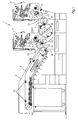
- FIG. 1 a sheet-fed printing machine 1 with printing units 2, 3 and a boom 4 is shown.
- the sheet-fed printing machine 1 is a perfector and comprises sheet transport cylinders 5 to 7, each with at least one gripper system 8.
- the sheet transport cylinders 5, 6 are impression cylinders of the printing units 2, 3.
- the sheet transport cylinder 7 is a transfer cylinder.
- the boom 4 comprises a chain conveyor 9 with gripper systems 10.
- the chain conveyor 9 revolves around a so-called delivery drum 11.
- the sheet transport cylinders 5, 7 together form a transfer area 12, in which the printing material sheet 13 is transferred from the gripper system 8 of the sheet transport cylinder 5 into the gripper system 8 of the sheet transport cylinder 7.
- the sheet transport cylinder 6 forms, together with the chain conveyor 9, a further transfer area 15, in which the printing material sheet 13 is transferred from the gripper system 8 of the sheet transport cylinder 6 into one of the gripper systems 10 of the chain conveyor 9.
- a sheet guiding device 16 is arranged, which has a the transfer area 12 to be located end 17.
- a sheet guiding device 18 is arranged, which has an end 19 to the transfer area 15.
- FIG. 2 a substantially cup-shaped sheet guiding device with a comb-shaped edge 20 is shown.
- This sheet guide can the sheet guide 16 from FIG. 1 be, with the comb-shaped edge 20 is the end 17, and may also the sheet guiding device 18 from FIG. 1 be with the comb-shaped edge 20 is the end 19.
- the sheet guiding device has a concave guide surface 21 with blowing air nozzles 22.
- the comb-shaped edge 20 has tines 23 and intervening gaps 24.
- the grippers of the gripper system 8 of the sheet transport cylinder 6 or 7 go through the gaps 24 during the cylinder rotation. Close to the comb-shaped edge 20, an unloading device 25 for eliminating electrostatic charges of the printing material sheets 13 is arranged.
- the unloading device 25 is a so-called active unloading device, whose "deelectrification" serving conductor, the ionizer, is connected to a high voltage source generating an alternating high voltage.
- the discharge device 25 is a so-called anti-static bar or ionization bar.
- the comb-shaped edge 20 and in particular its tines 23 consist at least partially of a substantially electrically non-conductive material, preferably a plastic such. As polyacetal (POM) or polyphenylene sulfide (PPS). The electrical insulation effect of this material ensures a high efficiency of the unloading device 25.
- the discharged from the unloading 25 printing material sheet 13 no longer tend to smear fresh ink to the guide surface 21, since these discharged printing material 13 have no more static charges, which otherwise sticking the printing material 13 would cause on the guide surface 21.
- the sheet guiding device FIG. 2 consists of a first part 26 and a second part 27.
- the first part 26 is a blow box and the second part 27 is the comb-shaped edge 20.
- the second part 27 is formed as an attachment element, which is connected to the first part 26 via screws.
- the second part 27 is formed as a separate element, which, although rests against the first part 26, but is not connected to the latter. Instead, in this case the second part 27 is attached via a holder 28 to a blowing device 29, which in turn is attached via a further holder 30 on the machine frame 31.
- the first part 26 consists at least largely of an electrically conductive material, preferably of a metal.
- the guide surface 21 may be made of a steel sheet.
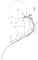
- FIG. 5 the case is shown in which the sheet guiding device FIG. 2 the delivery drum 11 is assigned. It is irrelevant whether the sheet guiding device 18 according to FIG. 3 as an attachment or according to FIG. 4 is designed as a separate element.
- a UV dryer 32 emits UV radiation 33 provided on the printing material sheet 13 for drying the printing ink, which UV radiation 33 partly reaches the interior of the skeleton-shaped delivery drum 11 and is deflected and reflected by the guide surface 21 towards the comb-shaped edge 20.
- the comb-shaped edge 20 here consists of polyphenylene sulfide (PPS) or in a comparable manner to the UV radiation 33 resistant and at the same time electrically insulating material.
- PPS polyphenylene sulfide
- the UV radiation resistance of the comb-shaped edge 20 prevents its premature aging, otherwise caused by the UV radiation 33 embrittlement and the like, so that the sheet guiding device 18 despite its proximity to the UV dryer 32 is not damaged by the latter.
- the guide surface 21 and the comb-shaped edge 20 are formed together as a single part.
- This part consists of an electrically conductive material and is z. B. a steel sheet.
- the part is coated in the region of the comb-shaped edge 20 with an insulating coating 36 whose electrical conductivity with respect to the electrical conductivity of the base material, for. B. the steel sheet, is significantly lower.
- FIG. 7 shows that in the region of ionizer tips 34 of the discharge device 25 in the guide surface 21 breakthroughs 35 are introduced, through which the ionizer tips 34 act on the printing material sheet 13.
Description
- Die vorliegende Erfindung bezieht sich auf eine Druckmaschine, mit einer Bogenleiteinrichtung, die einen Rand aufweist, nach dem Oberbegriff des Anspruchs 1.
- In
EP 0 922 576 B1 ist eine solche Druckmaschine beschrieben. Die Bogenleiteinrichtung dieser Druckmaschine des Standes der Technik weist jedoch keine günstigen Voraussetzungen für ein beidseitiges Bedrucken der Bogen auf. - Deshalb liegt der Erfindung die Aufgabe zugrunde, eine der eingangs genannten Gattung entsprechende Druckmaschine zu schaffen, bei welcher günstige Voraussetzungen für ein beidseitiges Bedrucken der Bogen gegeben sind.
- Diese Aufgabe wird durch eine Druckmaschine mit den Merkmalen des Anspruchs 1 gelöst.
- Besagtes Material, welches ein elektrischer Isolator ist, ermöglicht es, im Bereich des Randes die Entladeeinrichtung zum Entladen der Bedruckstoffbogen anzuordnen. Mittels einer solchen Entladeeinrichtung lassen sich die elektrostatischen Aufladungen des Bedruckstoffbogens bei dessen Einlauf in den Bereich der Bogenleiteinrichtung zumindest so stark reduzieren, dass der Bedruckstoffbogen infolgedessen nicht mehr dazu neigt, von der Bogenleiteinrichtung elektrostatisch angezogen zu werden und mit seiner beim Schön- und Wiederdruck der Bogenleiteinrichtung zugewandten Schöndruckseite an der Bogenleiteinrichtung abzuschmieren.
- Bei einer weiteren Weiterbildung besteht die Bogenleiteinrichtung überwiegend aus einem elektrisch leitfähigen Material. Bei weiteren Weiterbildungen ist das elektrisch im Wesentlichen nicht leitfähige Material Polyphenylensulfid oder Polyacetal.
- Bei einer weiteren Weiterbildung ist der Rand kammförmig und längserstreckt er sich quer relativ zu einer Bogenlaufrichtung der Bedruckstoffbogen.
- Weitere Weiterbildungen ergeben sich aus der nachfolgenden Beschreibung bevorzugter Ausführungsbeispiele und der dazugehörigen Zeichnung.
- In dieser zeigen:
- Figur 1
- eine Schön- und Wiederdruck-Offsetdruckmaschine mit Bogenleiteinrichtungen,
- Figur 2
- eine dreidimensionale Darstellung einer der Bogenleiteinrichtungen aus
Figur 1 , - Figur 3
- die Bogenleiteinrichtung aus
Figur 2 in einer Seitenansicht, - Figur 4
- eine Modifikation der Bogenleiteinrichtung aus
Figur 3 , mit gegenüber letzterer veränderter Befestigung eines kammförmigen Randelementes der Bogenleiteinrichtung, - Figur 5
- die Bogenleiteinrichtung aus
Figur 4 zusammen mit einem in der unmittelbaren Umgebung angeordneten UV-Trockner, - Figur 6
- ein Ausführungsbeispiel, bei dem eine der Bogenleiteinrichtungen aus
Figur 1 ein mit einem kammförmigen Rand versehenes Düsenblech aufweist, und - Figur 7
- eine Detaildarstellung des kammförmigen Randes der Bogenleiteinrichtung aus
Figur 6 und einer in unmittelbarer Nähe des kammförmigen Randes angeordneten Entladeeinrichtung. - In den
Figuren 1 bis 7 sind einander entsprechende Bauteile und Elemente mit den gleichen Bezugszeichen bezeichnet. - In
Figur 1 ist eine Bogendruckmaschine 1 mit Druckwerken 2, 3 und einem Ausleger 4 dargestellt. Die Bogendruckmaschine 1 ist ein Perfektor und umfasst Bogentransportzylinder 5 bis 7 mit jeweils mindestens einem Greifersystem 8. Die Bogentransportzylinder 5, 6 sind Gegendruckzylinder der Druckwerke 2, 3. Der Bogentransportzylinder 7 ist ein Übergabezylinder. Der Ausleger 4 umfasst einen Kettenförderer 9 mit Greifersystemen 10. Der Kettenförderer 9 läuft um eine sogenannte Auslagetrommel 11 um. Die Bogentransportzylinder 5, 7 bilden zusammen einen Übergabebereich 12, in welchem der Bedruckstoffbogen 13 aus dem Greifersystem 8 des Bogentransportzylinders 5 in das Greifersystem 8 des Bogentransportzylinders 7 übergeben wird. Der Bogentransportzylinder 6 bildet zusammen mit dem Kettenförderer 9 einen weiteren Übergabebereich 15, in welchem der Bedruckstoffbogen 13 aus dem Greifersystem 8 des Bogentransportzylinders 6 in eines der Greifersysteme 10 des Kettenförderers 9 übergeben wird. Unterhalb des Bogentransportzylinders 7 ist eine Bogenleiteinrichtung 16 angeordnet, die ein dem Übergabebereich 12 zu gelegenes Ende 17 hat. Unterhalb der Auslagetrommel 11 ist eine Bogenleiteinrichtung 18 angeordnet, die ein dem Übergabebereich 15 zu gelegenes Ende 19 hat. - In
Figur 2 ist eine im Wesentlichen schalenförmige Bogenleiteinrichtung mit einem kammförmigen Rand 20 dargestellt. Diese Bogenleiteinrichtung kann die Bogenleiteinrichtung 16 ausFigur 1 sein, wobei der kammförmige Rand 20 das Ende 17 ist, und kann auch die Bogenleiteinrichtung 18 ausFigur 1 sein, wobei der kammförmige Rand 20 das Ende 19 ist. Die Bogenleiteinrichtung hat eine konkave Leitfläche 21 mit blasenden Luftdüsen 22. Der kammförmige Rand 20 weist Zinken 23 und dazwischen liegende Lücken 24 auf. Die Greifer des Greifersystems 8 des Bogentransportzylinders 6 oder 7 durchlaufen während der Zylinderrotation die Lücken 24. Dicht bei dem kammförmigen Rand 20 ist eine Entladeeinrichtung 25 zum Beseitigen elektrostatischer Aufladungen der Bedruckstoffbogen 13 angeordnet. Die Entladeeinrichtung 25 ist eine sogenannte aktive Entladeeinrichtung, deren der "Entelektrisierung" dienender Leiter, der Ionisator, an eine eine Wechselhochspannung erzeugende Hochspannungsquelle angeschlossen ist. Die Entladeeinrichtung 25 ist ein sogenannter Ionensprühstab oder Ionisationsstab. Der kammförmige Rand 20 und insbesondere dessen Zinken 23 bestehen zumindest teilweise aus einem im Wesentlichen elektrisch nicht leitfähigen Material, vorzugsweise einem Kunststoff wie z. B. Polyacetal (POM) oder Polyphenylensulfid (PPS). Die elektrische Isolationswirkung dieses Materials gewährleistet einen hohen Wirkungsgrad der Entladeeinrichtung 25. Die von der Entladeeinrichtung 25 entladenen Bedruckstoffbogen 13 neigen nicht mehr zum Abschmieren frischer Druckfarbe an die Leitfläche 21, da diese entladenen Bedruckstoffbogen 13 keine statischen Aufladungen mehr aufweisen, welche ansonsten ein Haften der Bedruckstoffbogen 13 an der Leitfläche 21 verursachen würden. - In den
Figuren 3 und4 sind Ausführungsbeispiele dargestellt, bei denen die Bogenleiteinrichtung ausFigur 2 aus einem ersten Teil 26 und einem zweiten Teil 27 besteht. Das erste Teil 26 ist ein Blaskasten und das zweite Teil 27 ist der kammförmige Rand 20. - Gemäß
Figur 3 ist das zweite Teil 27 als ein Aufsatzelement ausgebildet, das mit dem ersten Teil 26 über Schrauben verbunden ist. - Gemäß
Figur 4 ist das zweite Teil 27 als ein Separatelement ausgebildet, welches zwar an dem ersten Teil 26 anliegt, jedoch mit letzterem nicht verbunden ist. Stattdessen ist hierbei das zweite Teil 27 über einen Halter 28 an einer Blaseinrichtung 29 befestigt, welche wiederum über einen weiteren Halter 30 am Maschinengestell 31 befestigt ist. - Sowohl bei dem in
Figur 3 gezeigten Ausführungsbeispiel als auch in dem inFigur 4 gezeigten besteht das den kammförmigen Rand 20 bildende Element massiv aus dem elektrisch nicht leitfähigen Material, z. B. besagtem POM oder PPS. Das erste Teil 26 besteht aber zumindest größtenteils aus einem elektrisch leitfähigen Material, vorzugsweise aus einem Metall. Beispielsweise kann die Leitfläche 21 aus einem Stahlblech gefertigt sein. - In
Figur 5 ist der Fall dargestellt, in welchem die Bogenleiteinrichtung ausFigur 2 der Auslagetrommel 11 beigeordnet ist. Dabei ist es unerheblich, ob die Bogenleiteinrichtung 18 gemäßFigur 3 als Aufsatzelement oder gemäßFigur 4 als Separatelement ausgebildet ist. Ein UV-Trockner 32 strahlt zum Trocknen der Druckfarbe auf dem Bedruckstoffbogen 13 vorgesehene UV-Strahlung 33 ab, welche teilweise in das Innere der skelettartig ausgebildeten Auslagetrommel 11 gelangt und von der Leitfläche 21 zum kammförmigen Rand 20 hin umgelenkt und reflektiert wird. Der kammförmige Rand 20 besteht hierbei aus Polyphenylensulfid (PPS) oder einem in vergleichbarer Weise gegen die UV-Strahlung 33 beständigen und zugleich elektrisch isolierenden Material. Die UV-Strahlungsresistenz des kammförmigen Randes 20 verhindert dessen vorzeitige Alterung, ansonsten von der UV-Strahlung 33 verursachte Versprödung und dergleichen, so dass die Bogenleiteinrichtung 18 trotz ihrer Nähe zum UV-Trockner 32 von letzterem nicht beschädigt wird. - Bei dem in den
Figuren 6 und7 dargestellten Ausführungsbeispiel sind die Leitfläche 21 und der kammförmige Rand 20 zusammen als ein einziges Teil ausgebildet. Dieses Teil besteht aus einem elektrisch leitfähigen Material und ist z. B. ein Stahlblech. Das Teil ist im Bereich des kammförmigen Randes 20 mit einer Isolierbeschichtung 36 beschichtet, deren elektrische Leitfähigkeit gegenüber der elektrischen Leitfähigkeit des Basismaterials, z. B. des Stahlbleches, deutlich geringer ist.Figur 7 zeigt, dass im Bereich von Ionisatorspitzen 34 der Entladeeinrichtung 25 in die Leitfläche 21 Durchbrüche 35 eingebracht sind, durch welche hindurch die Ionisatorspitzen 34 auf den Bedruckstoffbogen 13 einwirken. - Zeichnerisch nicht dargestellt sind Modifikationen der in den
Figuren 2 bis 4 dargestellten Ausführungsbeispielen, bei welchen Modifikation das den kammförmigen Rand 20 bildende Aufsatz- bzw. Nachbarelement aus einem elektrisch leitfähigen Material, z. B. Stahl, besteht und dieses Material ähnlich wie bei dem in denFiguren 6 und7 dargestellten Ausführungsbeispiel mit einer elektrischen Isolierbeschichtung versehen ist. -
- 1
- Bogendruckmaschine
- 2
- Druckwerk
- 3
- Druckwerk
- 4
- Ausleger
- 5
- Bogentransportzylinder
- 6
- Bogentransportzylinder
- 7
- Bogentransportzylinder
- 8
- Greifersystem
- 9
- Kettenförderer
- 10
- Greifersystem
- 11
- Auslagetrommel
- 12
- Übergabebereich
- 13
- Bedruckstoffbogen
- 14
- ./.
- 15
- Übergabebereich
- 16
- Bogenleiteinrichtung
- 17
- Ende
- 18
- Bogenleiteinrichtung
- 19
- Ende
- 20
- kammförmiger Rand
- 21
- Leitfläche
- 22
- Luftdüse
- 23
- Zinken
- 24
- Lücke
- 25
- Entladeeinrichtung
- 26
- erstes Teil
- 27
- zweites Teil
- 28
- Halter
- 29
- Blaseinrichtung
- 30
- Halter
- 31
- Maschinengestell
- 32
- UV-Trockner
- 33
- UV-Strahlung
- 34
- Ionisatorspitze
- 35
- Durchbruch
- 36
- Isolierbeschichtung
Claims (6)
- Druckmaschine (1), mit einer Bogenleiteinrichtung (16, 18), die einen Rand (20) aufweist, und
dass der Rand (20) zumindest teilweise aus einem elektrisch im Wesentlichen nicht leitfähigen Material besteht, dadurch gekennzeichnet,
dass im Bereich des Randes (20) eine Entladeeinrichtung (25) zum Entladen der Bedruckstoffbogen (13) angeordnet ist. - Druckmaschine nach Anspruch 1,
dadurch gekennzeichnet,
dass die Bogenleiteinrichtung (16, 18) überwiegend aus einem elektrisch leitfähigen Material besteht. - Druckmaschine nach Anspruch 1 oder 2,
dadurch gekennzeichnet,
dass das elektrisch im Wesentlichen nicht leitfähige Material Polyphenylensulfid ist. - Druckmaschine nach Anspruch 1 oder 2,
dadurch gekennzeichnet,
dass das elektrisch im Wesentlichen nicht leitfähige Material Polyacetal ist. - Druckmaschine nach einem der Ansprüche 1 bis 4,
dadurch gekennzeichnet,
dass sich der Rand (20) quer relativ zu einer Bogenlaufrichtung der Bedruckstoffbogen (13) längserstreckt. - Druckmaschine nach einem der Ansprüche 1 bis 5,
dadurch gekennzeichnet,
dass der Rand (20) ein kammförmiger Rand (20) ist.
Applications Claiming Priority (2)
| Application Number | Priority Date | Filing Date | Title |
|---|---|---|---|
| DE102005000892 | 2005-01-07 | ||
| DE102005032601A DE102005032601A1 (de) | 2005-01-07 | 2005-07-13 | Druckmaschine |
Publications (3)
| Publication Number | Publication Date |
|---|---|
| EP1679187A2 EP1679187A2 (de) | 2006-07-12 |
| EP1679187A3 EP1679187A3 (de) | 2010-03-03 |
| EP1679187B1 true EP1679187B1 (de) | 2011-05-25 |
Family
ID=35907019
Family Applications (1)
| Application Number | Title | Priority Date | Filing Date |
|---|---|---|---|
| EP05112187A Active EP1679187B1 (de) | 2005-01-07 | 2005-12-15 | Bogenleiteinrichtung mit elektrisch isoliertem, kammförmigem Rand |
Country Status (6)
| Country | Link |
|---|---|
| US (1) | US20060150841A1 (de) |
| EP (1) | EP1679187B1 (de) |
| JP (1) | JP4833667B2 (de) |
| CN (1) | CN1799839B (de) |
| AT (1) | ATE510693T1 (de) |
| DE (1) | DE102005032601A1 (de) |
Cited By (5)
| Publication number | Priority date | Publication date | Assignee | Title |
|---|---|---|---|---|
| DE102019118565A1 (de) * | 2019-07-09 | 2021-01-14 | Koenig & Bauer Ag | Bogenverarbeitende Maschine und Verfahren zum Fördern von Bogen |
| DE102019118571A1 (de) * | 2019-07-09 | 2021-01-14 | Koenig & Bauer Ag | Bogenverarbeitende Maschine und Verfahren zum Fördern von Bogen |
| DE102019118566A1 (de) * | 2019-07-09 | 2021-01-14 | Koenig & Bauer Ag | Bogenverarbeitende Maschine und Verfahren zum Fördern von Bogen |
| DE102019118569A1 (de) * | 2019-07-09 | 2021-01-14 | Koenig & Bauer Ag | Bogenverarbeitende Maschine und Verfahren zum Fördern von Bogen |
| WO2021004696A1 (de) | 2019-07-09 | 2021-01-14 | Koenig & Bauer Ag | Bogenverarbeitende maschine mit einer wendeeinrichtung, verfahren zum fördern von bogen und verwendung von entionisationseinrichtungen enthaltenden bogenleitelementen |
Families Citing this family (6)
| Publication number | Priority date | Publication date | Assignee | Title |
|---|---|---|---|---|
| DE102008009156B4 (de) | 2007-02-23 | 2018-11-08 | Heidelberger Druckmaschinen Ag | Anordnung zum Ableiten elektrostatischer Ladungen von einem Bedruckstoff |
| DE102008034766A1 (de) * | 2008-07-25 | 2010-01-28 | Heidelberger Druckmaschinen Ag | Bogenführungselement aus antistatischem Kunststoff |
| DE102010028595B4 (de) * | 2010-05-05 | 2021-06-10 | manroland sheetfed GmbH | Bogenverarbeitungsmaschine mit kammförmiger Bogenleiteinrichtung |
| US8462480B2 (en) | 2010-05-26 | 2013-06-11 | Illinois Tool Works Inc. | In-line gas ionizer with static dissipative material and counterelectrode |
| DE102022104772A1 (de) | 2022-03-01 | 2023-09-07 | Heidelberger Druckmaschinen Aktiengesellschaft | Vorrichtung zum Leiten von Druckbogen in einer Druckmaschine |
| DE102023103112B3 (de) | 2023-02-09 | 2023-12-14 | Heidelberger Druckmaschinen Aktiengesellschaft | Vorrichtung zum Leiten von Bogen in einer Druckmaschine |
Family Cites Families (108)
| Publication number | Priority date | Publication date | Assignee | Title |
|---|---|---|---|---|
| US3495269A (en) * | 1966-12-19 | 1970-02-10 | Xerox Corp | Electrographic recording method and apparatus with inert gaseous discharge ionization and acceleration gaps |
| US3496352A (en) * | 1967-06-05 | 1970-02-17 | Xerox Corp | Self-cleaning corona generating apparatus |
| JPS5130491A (ja) * | 1974-09-09 | 1976-03-15 | Kasuga Electric Co | Seidenkijokyosochodenkyoku |
| US4015203A (en) * | 1975-12-31 | 1977-03-29 | International Business Machines Corporation | Contactless LSI junction leakage testing method |
| US4247203A (en) * | 1978-04-03 | 1981-01-27 | Kla Instrument Corporation | Automatic photomask inspection system and apparatus |
| US4440082A (en) * | 1978-11-13 | 1984-04-03 | Dayco Corporation | Electrostatically assisted printing system |
| US4378159A (en) * | 1981-03-30 | 1983-03-29 | Tencor Instruments | Scanning contaminant and defect detector |
| US4448532A (en) * | 1981-03-31 | 1984-05-15 | Kla Instruments Corporation | Automatic photomask inspection method and system |
| US4926489A (en) * | 1983-03-11 | 1990-05-15 | Kla Instruments Corporation | Reticle inspection system |
| US4579455A (en) * | 1983-05-09 | 1986-04-01 | Kla Instruments Corporation | Photomask inspection apparatus and method with improved defect detection |
| US4578810A (en) * | 1983-08-08 | 1986-03-25 | Itek Corporation | System for printed circuit board defect detection |
| JPS6062122A (ja) * | 1983-09-16 | 1985-04-10 | Fujitsu Ltd | マスクパターンの露光方法 |
| US4595289A (en) * | 1984-01-25 | 1986-06-17 | At&T Bell Laboratories | Inspection system utilizing dark-field illumination |
| US4580775A (en) * | 1984-03-02 | 1986-04-08 | Ikegani Tsushinki Company, Ltd. | Sheet sorting apparatus |
| JPS60263807A (ja) * | 1984-06-12 | 1985-12-27 | Dainippon Screen Mfg Co Ltd | プリント配線板のパタ−ン欠陥検査装置 |
| US4817123A (en) * | 1984-09-21 | 1989-03-28 | Picker International | Digital radiography detector resolution improvement |
| US4734721A (en) * | 1985-10-04 | 1988-03-29 | Markem Corporation | Electrostatic printer utilizing dehumidified air |
| US4641967A (en) * | 1985-10-11 | 1987-02-10 | Tencor Instruments | Particle position correlator and correlation method for a surface scanner |
| US4928313A (en) * | 1985-10-25 | 1990-05-22 | Synthetic Vision Systems, Inc. | Method and system for automatically visually inspecting an article |
| DE3601660A1 (de) * | 1986-01-21 | 1987-07-23 | Eltex Elektrostatik Gmbh | Verfahren und vorrichtung zum falzen von aus einer fortlaufenden materialbahn abgeschnittenen bogen |
| US4814829A (en) * | 1986-06-12 | 1989-03-21 | Canon Kabushiki Kaisha | Projection exposure apparatus |
| US4805123B1 (en) * | 1986-07-14 | 1998-10-13 | Kla Instr Corp | Automatic photomask and reticle inspection method and apparatus including improved defect detector and alignment sub-systems |
| US4812756A (en) * | 1987-08-26 | 1989-03-14 | International Business Machines Corporation | Contactless technique for semicondutor wafer testing |
| JP3707172B2 (ja) * | 1996-01-24 | 2005-10-19 | 富士ゼロックス株式会社 | 画像読取装置 |
| US5205217A (en) * | 1990-12-31 | 1993-04-27 | Howard W. DeMoore | Vacuum transfer apparatus for rotary sheet-fed printing presses |
| JPH04312796A (ja) * | 1991-04-10 | 1992-11-04 | Kitagawa Ind Co Ltd | 帯電防止用イオン発生装置 |
| US5189481A (en) * | 1991-07-26 | 1993-02-23 | Tencor Instruments | Particle detector for rough surfaces |
| DE69208413T2 (de) * | 1991-08-22 | 1996-11-14 | Kla Instr Corp | Gerät zur automatischen Prüfung von Photomaske |
| US5563702A (en) * | 1991-08-22 | 1996-10-08 | Kla Instruments Corporation | Automated photomask inspection apparatus and method |
| JP2512258B2 (ja) * | 1992-03-11 | 1996-07-03 | 松下電器産業株式会社 | シ―ト給送装置 |
| JP2667940B2 (ja) * | 1992-04-27 | 1997-10-27 | 三菱電機株式会社 | マスク検査方法およびマスク検出装置 |
| US5448053A (en) * | 1993-03-01 | 1995-09-05 | Rhoads; Geoffrey B. | Method and apparatus for wide field distortion-compensated imaging |
| US5500607A (en) * | 1993-12-22 | 1996-03-19 | International Business Machines Corporation | Probe-oxide-semiconductor method and apparatus for measuring oxide charge on a semiconductor wafer |
| US5608538A (en) * | 1994-08-24 | 1997-03-04 | International Business Machines Corporation | Scan line queuing for high performance image correction |
| US5572608A (en) * | 1994-08-24 | 1996-11-05 | International Business Machines Corporation | Sinc filter in linear lumen space for scanner |
| US5528153A (en) * | 1994-11-07 | 1996-06-18 | Texas Instruments Incorporated | Method for non-destructive, non-contact measurement of dielectric constant of thin films |
| CA2139182A1 (en) * | 1994-12-28 | 1996-06-29 | Paul Chevrette | Method and system for fast microscanning |
| US5485091A (en) * | 1995-05-12 | 1996-01-16 | International Business Machines Corporation | Contactless electrical thin oxide measurements |
| US6288780B1 (en) * | 1995-06-06 | 2001-09-11 | Kla-Tencor Technologies Corp. | High throughput brightfield/darkfield wafer inspection system using advanced optical techniques |
| JPH0919999A (ja) * | 1995-07-07 | 1997-01-21 | Toray Ind Inc | 静電気除去装置を備えた印刷機及び印刷方法 |
| US5594247A (en) * | 1995-07-07 | 1997-01-14 | Keithley Instruments, Inc. | Apparatus and method for depositing charge on a semiconductor wafer |
| US5773989A (en) * | 1995-07-14 | 1998-06-30 | University Of South Florida | Measurement of the mobile ion concentration in the oxide layer of a semiconductor wafer |
| US5621519A (en) * | 1995-07-31 | 1997-04-15 | Neopath, Inc. | Imaging system transfer function control method and apparatus |
| US5619548A (en) * | 1995-08-11 | 1997-04-08 | Oryx Instruments And Materials Corp. | X-ray thickness gauge |
| US5754678A (en) * | 1996-01-17 | 1998-05-19 | Photon Dynamics, Inc. | Substrate inspection apparatus and method |
| US5742658A (en) * | 1996-05-23 | 1998-04-21 | Advanced Micro Devices, Inc. | Apparatus and method for determining the elemental compositions and relative locations of particles on the surface of a semiconductor wafer |
| US5767693A (en) * | 1996-09-04 | 1998-06-16 | Smithley Instruments, Inc. | Method and apparatus for measurement of mobile charges with a corona screen gun |
| US6076465A (en) * | 1996-09-20 | 2000-06-20 | Kla-Tencor Corporation | System and method for determining reticle defect printability |
| KR100200734B1 (ko) * | 1996-10-10 | 1999-06-15 | 윤종용 | 에어리얼 이미지 측정 장치 및 방법 |
| US5866806A (en) * | 1996-10-11 | 1999-02-02 | Kla-Tencor Corporation | System for locating a feature of a surface |
| US5928389A (en) * | 1996-10-21 | 1999-07-27 | Applied Materials, Inc. | Method and apparatus for priority based scheduling of wafer processing within a multiple chamber semiconductor wafer processing tool |
| DE29702626U1 (de) * | 1997-02-15 | 1997-04-03 | Roland Man Druckmasch | Entstaubungssystem mit Bogenführungseinrichtung |
| US5889593A (en) * | 1997-02-26 | 1999-03-30 | Kla Instruments Corporation | Optical system and method for angle-dependent reflection or transmission measurement |
| US6097196A (en) * | 1997-04-23 | 2000-08-01 | Verkuil; Roger L. | Non-contact tunnelling field measurement for a semiconductor oxide layer |
| US6078738A (en) * | 1997-05-08 | 2000-06-20 | Lsi Logic Corporation | Comparing aerial image to SEM of photoresist or substrate pattern for masking process characterization |
| US6201999B1 (en) * | 1997-06-09 | 2001-03-13 | Applied Materials, Inc. | Method and apparatus for automatically generating schedules for wafer processing within a multichamber semiconductor wafer processing tool |
| US6011404A (en) * | 1997-07-03 | 2000-01-04 | Lucent Technologies Inc. | System and method for determining near--surface lifetimes and the tunneling field of a dielectric in a semiconductor |
| US6072320A (en) * | 1997-07-30 | 2000-06-06 | Verkuil; Roger L. | Product wafer junction leakage measurement using light and eddy current |
| US6191605B1 (en) * | 1997-08-18 | 2001-02-20 | Tom G. Miller | Contactless method for measuring total charge of an insulating layer on a substrate using corona charge |
| JP3671617B2 (ja) * | 1997-09-01 | 2005-07-13 | コニカミノルタホールディングス株式会社 | 画像形成装置 |
| US6757645B2 (en) * | 1997-09-17 | 2004-06-29 | Numerical Technologies, Inc. | Visual inspection and verification system |
| US7107571B2 (en) * | 1997-09-17 | 2006-09-12 | Synopsys, Inc. | Visual analysis and verification system using advanced tools |
| US5874733A (en) * | 1997-10-16 | 1999-02-23 | Raytheon Company | Convergent beam scanner linearizing method and apparatus |
| US6233719B1 (en) * | 1997-10-27 | 2001-05-15 | Kla-Tencor Corporation | System and method for analyzing semiconductor production data |
| JPH11207927A (ja) * | 1997-11-05 | 1999-08-03 | Heidelberger Druckmas Ag | 枚葉紙輪転印刷機のためのリニア駆動装置を有する反転装置 |
| DE29720989U1 (de) | 1997-11-27 | 1998-01-08 | Roland Man Druckmasch | Bogenführungseinrichtung mit einer Leitfläche in einer Druckmaschine |
| US6060709A (en) * | 1997-12-31 | 2000-05-09 | Verkuil; Roger L. | Apparatus and method for depositing uniform charge on a thin oxide semiconductor wafer |
| US6175645B1 (en) * | 1998-01-22 | 2001-01-16 | Applied Materials, Inc. | Optical inspection method and apparatus |
| US6171737B1 (en) * | 1998-02-03 | 2001-01-09 | Advanced Micro Devices, Inc. | Low cost application of oxide test wafer for defect monitor in photolithography process |
| US6324298B1 (en) * | 1998-07-15 | 2001-11-27 | August Technology Corp. | Automated wafer defect inspection system and a process of performing such inspection |
| US6466314B1 (en) * | 1998-09-17 | 2002-10-15 | Applied Materials, Inc. | Reticle design inspection system |
| US6535628B2 (en) * | 1998-10-15 | 2003-03-18 | Applied Materials, Inc. | Detection of wafer fragments in a wafer processing apparatus |
| AU3676500A (en) * | 1999-05-07 | 2000-11-21 | Nikon Corporation | Aligner, microdevice, photomask, exposure method, and method of manufacturing device |
| EP1190238A1 (de) * | 1999-05-18 | 2002-03-27 | Applied Materials, Inc. | Verfahren und vorrichtung zur überprüfung von artikeln durch vergleich mit einem master |
| FR2801673B1 (fr) * | 1999-11-26 | 2001-12-28 | Pechiney Aluminium | Procede de mesure du degre et de l'homogeneite de calcination des alumines |
| US7190292B2 (en) * | 1999-11-29 | 2007-03-13 | Bizjak Karl M | Input level adjust system and method |
| US6701004B1 (en) * | 1999-12-22 | 2004-03-02 | Intel Corporation | Detecting defects on photomasks |
| US6569691B1 (en) * | 2000-03-29 | 2003-05-27 | Semiconductor Diagnostics, Inc. | Measurement of different mobile ion concentrations in the oxide layer of a semiconductor wafer |
| DE10023841B4 (de) * | 2000-05-16 | 2004-05-06 | Manfred Rachner Gmbh | Wendevorrichtung für aus einzelnen Blättern bestehende Einzelstapel |
| JP3833050B2 (ja) * | 2000-05-17 | 2006-10-11 | キヤノン株式会社 | 画像形成装置 |
| US7135676B2 (en) * | 2000-06-27 | 2006-11-14 | Ebara Corporation | Inspection system by charged particle beam and method of manufacturing devices using the system |
| US6513151B1 (en) * | 2000-09-14 | 2003-01-28 | Advanced Micro Devices, Inc. | Full flow focus exposure matrix analysis and electrical testing for new product mask evaluation |
| US6680621B2 (en) * | 2001-01-26 | 2004-01-20 | Semiconductor Diagnostics, Inc. | Steady state method for measuring the thickness and the capacitance of ultra thin dielectric in the presence of substantial leakage current |
| JP4199939B2 (ja) * | 2001-04-27 | 2008-12-24 | 株式会社日立製作所 | 半導体検査システム |
| CN1738429A (zh) * | 2001-09-12 | 2006-02-22 | 松下电器产业株式会社 | 图像解码方法 |
| JP3955450B2 (ja) * | 2001-09-27 | 2007-08-08 | 株式会社ルネサステクノロジ | 試料検査方法 |
| US6734696B2 (en) * | 2001-11-01 | 2004-05-11 | Kla-Tencor Technologies Corp. | Non-contact hysteresis measurements of insulating films |
| EP1352738A3 (de) * | 2002-04-08 | 2004-08-04 | Komori Corporation | Gerät zum Führen von Bögen |
| JP2004031709A (ja) * | 2002-06-27 | 2004-01-29 | Seiko Instruments Inc | ウエハレス測長レシピ生成装置 |
| US7012438B1 (en) * | 2002-07-10 | 2006-03-14 | Kla-Tencor Technologies Corp. | Methods and systems for determining a property of an insulating film |
| EP1523696B1 (de) * | 2002-07-15 | 2016-12-21 | KLA-Tencor Corporation | Defektinspektionsmethoden, die das aufnehmen des projizierten maskenabbildes unter verschiedenen lithographischen prozessvariablen beinhalten |
| EP1384748B1 (de) * | 2002-07-22 | 2007-06-13 | Toyoda Gosei Co., Ltd. | Kunststoffteil und Verfarhen zur Herstellung desselben |
| JP2004069884A (ja) * | 2002-08-05 | 2004-03-04 | Brother Ind Ltd | 画像読み取り手段を有する画像形成装置 |
| US7043071B2 (en) * | 2002-09-13 | 2006-05-09 | Synopsys, Inc. | Soft defect printability simulation and analysis for masks |
| KR100474571B1 (ko) * | 2002-09-23 | 2005-03-10 | 삼성전자주식회사 | 웨이퍼의 패턴 검사용 기준 이미지 설정 방법과 이 설정방법을 이용한 패턴 검사 방법 및 장치 |
| US7379175B1 (en) * | 2002-10-15 | 2008-05-27 | Kla-Tencor Technologies Corp. | Methods and systems for reticle inspection and defect review using aerial imaging |
| US7027143B1 (en) * | 2002-10-15 | 2006-04-11 | Kla-Tencor Technologies Corp. | Methods and systems for inspecting reticles using aerial imaging at off-stepper wavelengths |
| US6807503B2 (en) * | 2002-11-04 | 2004-10-19 | Brion Technologies, Inc. | Method and apparatus for monitoring integrated circuit fabrication |
| US7457736B2 (en) * | 2002-11-21 | 2008-11-25 | Synopsys, Inc. | Automated creation of metrology recipes |
| JP4144366B2 (ja) * | 2003-02-10 | 2008-09-03 | ブラザー工業株式会社 | 熱定着装置および画像形成装置 |
| US7053355B2 (en) * | 2003-03-18 | 2006-05-30 | Brion Technologies, Inc. | System and method for lithography process monitoring and control |
| US6859746B1 (en) * | 2003-05-01 | 2005-02-22 | Advanced Micro Devices, Inc. | Methods of using adaptive sampling techniques based upon categorization of process variations, and system for performing same |
| US7135344B2 (en) * | 2003-07-11 | 2006-11-14 | Applied Materials, Israel, Ltd. | Design-based monitoring |
| US6988045B2 (en) * | 2003-08-04 | 2006-01-17 | Advanced Micro Devices, Inc. | Dynamic metrology sampling methods, and system for performing same |
| CA2573217C (en) * | 2004-08-09 | 2013-04-09 | Bracco Research Sa | An image registration method and apparatus for medical imaging based on mulptiple masks |
| US7310796B2 (en) * | 2004-08-27 | 2007-12-18 | Applied Materials, Israel, Ltd. | System and method for simulating an aerial image |
| DE102004058377A1 (de) * | 2004-12-03 | 2006-06-14 | Man Roland Druckmaschinen Ag | Bogenleiteinrichtung für eine bogenverarbeitende Maschine, insbesondere Rotationsbogendruckmaschine |
| US20070002322A1 (en) * | 2005-06-30 | 2007-01-04 | Yan Borodovsky | Image inspection method |
-
2005
- 2005-07-13 DE DE102005032601A patent/DE102005032601A1/de not_active Withdrawn
- 2005-12-15 EP EP05112187A patent/EP1679187B1/de active Active
- 2005-12-15 AT AT05112187T patent/ATE510693T1/de active
-
2006
- 2006-01-06 CN CN2006100057838A patent/CN1799839B/zh active Active
- 2006-01-09 US US11/328,414 patent/US20060150841A1/en not_active Abandoned
- 2006-01-10 JP JP2006002300A patent/JP4833667B2/ja active Active
Cited By (14)
| Publication number | Priority date | Publication date | Assignee | Title |
|---|---|---|---|---|
| DE102019118565A1 (de) * | 2019-07-09 | 2021-01-14 | Koenig & Bauer Ag | Bogenverarbeitende Maschine und Verfahren zum Fördern von Bogen |
| DE102019118571A1 (de) * | 2019-07-09 | 2021-01-14 | Koenig & Bauer Ag | Bogenverarbeitende Maschine und Verfahren zum Fördern von Bogen |
| DE102019118566A1 (de) * | 2019-07-09 | 2021-01-14 | Koenig & Bauer Ag | Bogenverarbeitende Maschine und Verfahren zum Fördern von Bogen |
| DE102019118569A1 (de) * | 2019-07-09 | 2021-01-14 | Koenig & Bauer Ag | Bogenverarbeitende Maschine und Verfahren zum Fördern von Bogen |
| WO2021004696A1 (de) | 2019-07-09 | 2021-01-14 | Koenig & Bauer Ag | Bogenverarbeitende maschine mit einer wendeeinrichtung, verfahren zum fördern von bogen und verwendung von entionisationseinrichtungen enthaltenden bogenleitelementen |
| DE102019118569B4 (de) | 2019-07-09 | 2022-05-12 | Koenig & Bauer Ag | Bogenverarbeitende Maschine und Verfahren zum Fördern von Bogen |
| DE102019118571B4 (de) | 2019-07-09 | 2022-05-25 | Koenig & Bauer Ag | Bogenverarbeitende Maschine und Verfahren zum Fördern von Bogen |
| DE102019118566B4 (de) | 2019-07-09 | 2022-07-14 | Koenig & Bauer Ag | Bogenverarbeitende Maschine und Verfahren zum Fördern von Bogen |
| DE102019118565B4 (de) | 2019-07-09 | 2022-07-21 | Koenig & Bauer Ag | Bogenverarbeitende Maschine und Verfahren zum Fördern von Bogen |
| US11498790B2 (en) | 2019-07-09 | 2022-11-15 | Koenig & Bauer Ag | Sheet-processing machine comprising a turning device, method for conveying sheets, and use of sheet guide elements containing deionization devices |
| EP4209350A1 (de) | 2019-07-09 | 2023-07-12 | Koenig & Bauer AG | Bogenverarbeitende maschine, verwendung der bogenverarbeitenden maschine und verfahren zum fördern von bogen |
| EP4209351A1 (de) | 2019-07-09 | 2023-07-12 | Koenig & Bauer AG | Bogenverarbeitende maschine, verwendung der bogenverarbeitenden maschine, verfahren zum fördern von bogen und verwendung von entionisationseinrichtungen enthaltenden bogenleitelementen |
| EP4209349A1 (de) | 2019-07-09 | 2023-07-12 | Koenig & Bauer AG | Bogenverarbeitende maschine, verwendung der bogenverarbeitenden maschine, verfahren zum fördern von bogen und verwendung von entionisationseinrichtungen enthaltenden bogenleitelementen |
| EP4209352A1 (de) | 2019-07-09 | 2023-07-12 | Koenig & Bauer AG | Foliebogenverarbeitende maschine, verwendung der foliebogenverarbeitenden maschine, verfahren zum fördern von bogen und verwendung von entionisationseinrichtungen enthaltenden bogenleitelementen |
Also Published As
| Publication number | Publication date |
|---|---|
| JP4833667B2 (ja) | 2011-12-07 |
| EP1679187A2 (de) | 2006-07-12 |
| CN1799839A (zh) | 2006-07-12 |
| DE102005032601A1 (de) | 2006-07-20 |
| ATE510693T1 (de) | 2011-06-15 |
| EP1679187A3 (de) | 2010-03-03 |
| CN1799839B (zh) | 2012-03-07 |
| JP2006188065A (ja) | 2006-07-20 |
| US20060150841A1 (en) | 2006-07-13 |
Similar Documents
| Publication | Publication Date | Title |
|---|---|---|
| EP1679187B1 (de) | Bogenleiteinrichtung mit elektrisch isoliertem, kammförmigem Rand | |
| EP1117487B1 (de) | Beschichtungsmaschine zum veredeln von bogenmaterial | |
| DE19857984B4 (de) | Mit Excimer-Strahlern arbeitender Trockner in Bogendruckmaschinen | |
| EP0306682B1 (de) | Vorrichtung zum Fördern von Bogen durch die Druckzone von Gummizylinder und Druckzylinder einer Bogenrotationsdruckmaschine | |
| DE19836022A1 (de) | Vorrichtung zum Bestäuben von bedruckten Bogen aus Papier o. dgl. | |
| DE102004011114B4 (de) | Bedruckstoffverarbeitungsmaschine | |
| EP1418049B1 (de) | Rotationsdruckmaschine | |
| DE102008009156B4 (de) | Anordnung zum Ableiten elektrostatischer Ladungen von einem Bedruckstoff | |
| EP1303407B1 (de) | Trocknereinrichtung innerhalb einer bogendruckmaschine | |
| DE19829095C2 (de) | Bogenführungseinrichtung in einer Druckmaschine | |
| CH619400A5 (de) | ||
| DE102012218048B4 (de) | Bogentransporttrommel, Verwendung von wechselbaren Überzügen an jeweiligen Zinken von Mantelsegmenten einer Bogentransporttrommel und Verfahren zum Einstellen von Kontakteigenschaften einer Bogentransporttrommel | |
| DE3040388A1 (de) | Bogenoffsetdruckmaschine mit mindestens einem druckwerk fuer schoen- und widerdruck | |
| CH651501A5 (en) | Sheet-fed rotary printing machine having at least one printing unit | |
| WO1998007568A1 (de) | Vorrichtung zum bestäuben bewegter gegenstände, insbesondere bedruckter papierbögen | |
| DE19611590C1 (de) | Bogenführende Trommel für eine Druckmaschine | |
| DE102010028702B4 (de) | Wendeeinrichtung einer Bogendruckmaschine | |
| EP1040061B1 (de) | Einrichtung zum elektrostatischen beeinflussen von signaturen | |
| DE102014224896A1 (de) | Bogenverarbeitende Maschine und Verfahren zum Lackieren der Bogenvorderseiten und/oder der Bogenrückseiten | |
| EP3863855B1 (de) | Vorrichtung, verfahren und druckmaschine zum mehrfachen bedrucken von bedruckstoffbogen | |
| DE102010028698A1 (de) | Bogenführungseinrichtung | |
| DE2715766A1 (de) | Verfahren zur elektrostatischen unterstuetzung des druckvorgangs und druckmaschinen mit einer elektrostatischen substrat-anpressung | |
| DE102010028701B4 (de) | Bogenführungseinrichtung | |
| DE10315173B4 (de) | Druckzylinder für Blechtafel-Druckmaschinen und dergleichen | |
| DE19958631A1 (de) | Bogenoffsetdruckmaschine |
Legal Events
| Date | Code | Title | Description |
|---|---|---|---|
| PUAI | Public reference made under article 153(3) epc to a published international application that has entered the european phase |
Free format text: ORIGINAL CODE: 0009012 |
|
| AK | Designated contracting states |
Kind code of ref document: A2 Designated state(s): AT BE BG CH CY CZ DE DK EE ES FI FR GB GR HU IE IS IT LI LT LU LV MC NL PL PT RO SE SI SK TR |
|
| AX | Request for extension of the european patent |
Extension state: AL BA HR MK YU |
|
| PUAL | Search report despatched |
Free format text: ORIGINAL CODE: 0009013 |
|
| AK | Designated contracting states |
Kind code of ref document: A3 Designated state(s): AT BE BG CH CY CZ DE DK EE ES FI FR GB GR HU IE IS IT LI LT LU LV MC NL PL PT RO SE SI SK TR |
|
| AX | Request for extension of the european patent |
Extension state: AL BA HR MK YU |
|
| 17P | Request for examination filed |
Effective date: 20100903 |
|
| 17Q | First examination report despatched |
Effective date: 20100928 |
|
| AKX | Designation fees paid |
Designated state(s): AT BE BG CH CY CZ DE DK EE ES FI FR GB GR HU IE IS IT LI LT LU LV MC NL PL PT RO SE SI SK TR |
|
| RIC1 | Information provided on ipc code assigned before grant |
Ipc: B41F 21/00 20060101AFI20101021BHEP |
|
| GRAP | Despatch of communication of intention to grant a patent |
Free format text: ORIGINAL CODE: EPIDOSNIGR1 |
|
| GRAS | Grant fee paid |
Free format text: ORIGINAL CODE: EPIDOSNIGR3 |
|
| GRAA | (expected) grant |
Free format text: ORIGINAL CODE: 0009210 |
|
| REG | Reference to a national code |
Ref country code: DE Ref legal event code: R081 Ref document number: 502005011426 Country of ref document: DE Owner name: HEIDELBERGER DRUCKMASCHINEN AG, DE Free format text: FORMER OWNER: HEIDELBERGER DRUCKMASCHINEN AG, 69115 HEIDELBERG, DE |
|
| AK | Designated contracting states |
Kind code of ref document: B1 Designated state(s): AT BE BG CH CY CZ DE DK EE ES FI FR GB GR HU IE IS IT LI LT LU LV MC NL PL PT RO SE SI SK TR |
|
| REG | Reference to a national code |
Ref country code: GB Ref legal event code: FG4D Free format text: NOT ENGLISH |
|
| REG | Reference to a national code |
Ref country code: CH Ref legal event code: EP |
|
| REG | Reference to a national code |
Ref country code: IE Ref legal event code: FG4D Free format text: LANGUAGE OF EP DOCUMENT: GERMAN |
|
| REG | Reference to a national code |
Ref country code: DE Ref legal event code: R096 Ref document number: 502005011426 Country of ref document: DE Effective date: 20110707 |
|
| REG | Reference to a national code |
Ref country code: NL Ref legal event code: VDEP Effective date: 20110525 |
|
| PG25 | Lapsed in a contracting state [announced via postgrant information from national office to epo] |
Ref country code: PT Free format text: LAPSE BECAUSE OF FAILURE TO SUBMIT A TRANSLATION OF THE DESCRIPTION OR TO PAY THE FEE WITHIN THE PRESCRIBED TIME-LIMIT Effective date: 20110926 Ref country code: LT Free format text: LAPSE BECAUSE OF FAILURE TO SUBMIT A TRANSLATION OF THE DESCRIPTION OR TO PAY THE FEE WITHIN THE PRESCRIBED TIME-LIMIT Effective date: 20110525 Ref country code: SE Free format text: LAPSE BECAUSE OF FAILURE TO SUBMIT A TRANSLATION OF THE DESCRIPTION OR TO PAY THE FEE WITHIN THE PRESCRIBED TIME-LIMIT Effective date: 20110525 |
|
| PG25 | Lapsed in a contracting state [announced via postgrant information from national office to epo] |
Ref country code: ES Free format text: LAPSE BECAUSE OF FAILURE TO SUBMIT A TRANSLATION OF THE DESCRIPTION OR TO PAY THE FEE WITHIN THE PRESCRIBED TIME-LIMIT Effective date: 20110905 Ref country code: IS Free format text: LAPSE BECAUSE OF FAILURE TO SUBMIT A TRANSLATION OF THE DESCRIPTION OR TO PAY THE FEE WITHIN THE PRESCRIBED TIME-LIMIT Effective date: 20110925 Ref country code: LV Free format text: LAPSE BECAUSE OF FAILURE TO SUBMIT A TRANSLATION OF THE DESCRIPTION OR TO PAY THE FEE WITHIN THE PRESCRIBED TIME-LIMIT Effective date: 20110525 Ref country code: GR Free format text: LAPSE BECAUSE OF FAILURE TO SUBMIT A TRANSLATION OF THE DESCRIPTION OR TO PAY THE FEE WITHIN THE PRESCRIBED TIME-LIMIT Effective date: 20110826 Ref country code: CY Free format text: LAPSE BECAUSE OF FAILURE TO SUBMIT A TRANSLATION OF THE DESCRIPTION OR TO PAY THE FEE WITHIN THE PRESCRIBED TIME-LIMIT Effective date: 20110525 Ref country code: FI Free format text: LAPSE BECAUSE OF FAILURE TO SUBMIT A TRANSLATION OF THE DESCRIPTION OR TO PAY THE FEE WITHIN THE PRESCRIBED TIME-LIMIT Effective date: 20110525 Ref country code: SI Free format text: LAPSE BECAUSE OF FAILURE TO SUBMIT A TRANSLATION OF THE DESCRIPTION OR TO PAY THE FEE WITHIN THE PRESCRIBED TIME-LIMIT Effective date: 20110525 |
|
| REG | Reference to a national code |
Ref country code: IE Ref legal event code: FD4D |
|
| PG25 | Lapsed in a contracting state [announced via postgrant information from national office to epo] |
Ref country code: NL Free format text: LAPSE BECAUSE OF FAILURE TO SUBMIT A TRANSLATION OF THE DESCRIPTION OR TO PAY THE FEE WITHIN THE PRESCRIBED TIME-LIMIT Effective date: 20110525 |
|
| PG25 | Lapsed in a contracting state [announced via postgrant information from national office to epo] |
Ref country code: CZ Free format text: LAPSE BECAUSE OF FAILURE TO SUBMIT A TRANSLATION OF THE DESCRIPTION OR TO PAY THE FEE WITHIN THE PRESCRIBED TIME-LIMIT Effective date: 20110525 Ref country code: IE Free format text: LAPSE BECAUSE OF FAILURE TO SUBMIT A TRANSLATION OF THE DESCRIPTION OR TO PAY THE FEE WITHIN THE PRESCRIBED TIME-LIMIT Effective date: 20110525 Ref country code: EE Free format text: LAPSE BECAUSE OF FAILURE TO SUBMIT A TRANSLATION OF THE DESCRIPTION OR TO PAY THE FEE WITHIN THE PRESCRIBED TIME-LIMIT Effective date: 20110525 |
|
| PG25 | Lapsed in a contracting state [announced via postgrant information from national office to epo] |
Ref country code: PL Free format text: LAPSE BECAUSE OF FAILURE TO SUBMIT A TRANSLATION OF THE DESCRIPTION OR TO PAY THE FEE WITHIN THE PRESCRIBED TIME-LIMIT Effective date: 20110525 Ref country code: RO Free format text: LAPSE BECAUSE OF FAILURE TO SUBMIT A TRANSLATION OF THE DESCRIPTION OR TO PAY THE FEE WITHIN THE PRESCRIBED TIME-LIMIT Effective date: 20110525 Ref country code: SK Free format text: LAPSE BECAUSE OF FAILURE TO SUBMIT A TRANSLATION OF THE DESCRIPTION OR TO PAY THE FEE WITHIN THE PRESCRIBED TIME-LIMIT Effective date: 20110525 Ref country code: DK Free format text: LAPSE BECAUSE OF FAILURE TO SUBMIT A TRANSLATION OF THE DESCRIPTION OR TO PAY THE FEE WITHIN THE PRESCRIBED TIME-LIMIT Effective date: 20110525 |
|
| PLBE | No opposition filed within time limit |
Free format text: ORIGINAL CODE: 0009261 |
|
| STAA | Information on the status of an ep patent application or granted ep patent |
Free format text: STATUS: NO OPPOSITION FILED WITHIN TIME LIMIT |
|
| 26N | No opposition filed |
Effective date: 20120228 |
|
| PG25 | Lapsed in a contracting state [announced via postgrant information from national office to epo] |
Ref country code: IT Free format text: LAPSE BECAUSE OF FAILURE TO SUBMIT A TRANSLATION OF THE DESCRIPTION OR TO PAY THE FEE WITHIN THE PRESCRIBED TIME-LIMIT Effective date: 20110525 |
|
| REG | Reference to a national code |
Ref country code: DE Ref legal event code: R097 Ref document number: 502005011426 Country of ref document: DE Effective date: 20120228 |
|
| BERE | Be: lapsed |
Owner name: HEIDELBERGER DRUCKMASCHINEN A.G. Effective date: 20111231 |
|
| PG25 | Lapsed in a contracting state [announced via postgrant information from national office to epo] |
Ref country code: MC Free format text: LAPSE BECAUSE OF NON-PAYMENT OF DUE FEES Effective date: 20111231 |
|
| REG | Reference to a national code |
Ref country code: CH Ref legal event code: PL |
|
| GBPC | Gb: european patent ceased through non-payment of renewal fee |
Effective date: 20111215 |
|
| REG | Reference to a national code |
Ref country code: FR Ref legal event code: ST Effective date: 20120831 |
|
| PG25 | Lapsed in a contracting state [announced via postgrant information from national office to epo] |
Ref country code: GB Free format text: LAPSE BECAUSE OF NON-PAYMENT OF DUE FEES Effective date: 20111215 Ref country code: BE Free format text: LAPSE BECAUSE OF NON-PAYMENT OF DUE FEES Effective date: 20111231 Ref country code: CH Free format text: LAPSE BECAUSE OF NON-PAYMENT OF DUE FEES Effective date: 20111231 Ref country code: LI Free format text: LAPSE BECAUSE OF NON-PAYMENT OF DUE FEES Effective date: 20111231 |
|
| REG | Reference to a national code |
Ref country code: AT Ref legal event code: MM01 Ref document number: 510693 Country of ref document: AT Kind code of ref document: T Effective date: 20111215 |
|
| PG25 | Lapsed in a contracting state [announced via postgrant information from national office to epo] |
Ref country code: FR Free format text: LAPSE BECAUSE OF NON-PAYMENT OF DUE FEES Effective date: 20120102 |
|
| PG25 | Lapsed in a contracting state [announced via postgrant information from national office to epo] |
Ref country code: LU Free format text: LAPSE BECAUSE OF NON-PAYMENT OF DUE FEES Effective date: 20111215 |
|
| PG25 | Lapsed in a contracting state [announced via postgrant information from national office to epo] |
Ref country code: BG Free format text: LAPSE BECAUSE OF FAILURE TO SUBMIT A TRANSLATION OF THE DESCRIPTION OR TO PAY THE FEE WITHIN THE PRESCRIBED TIME-LIMIT Effective date: 20110825 Ref country code: AT Free format text: LAPSE BECAUSE OF NON-PAYMENT OF DUE FEES Effective date: 20111215 |
|
| PG25 | Lapsed in a contracting state [announced via postgrant information from national office to epo] |
Ref country code: TR Free format text: LAPSE BECAUSE OF FAILURE TO SUBMIT A TRANSLATION OF THE DESCRIPTION OR TO PAY THE FEE WITHIN THE PRESCRIBED TIME-LIMIT Effective date: 20110525 |
|
| PG25 | Lapsed in a contracting state [announced via postgrant information from national office to epo] |
Ref country code: HU Free format text: LAPSE BECAUSE OF FAILURE TO SUBMIT A TRANSLATION OF THE DESCRIPTION OR TO PAY THE FEE WITHIN THE PRESCRIBED TIME-LIMIT Effective date: 20110525 |
|
| REG | Reference to a national code |
Ref country code: DE Ref legal event code: R081 Ref document number: 502005011426 Country of ref document: DE Owner name: HEIDELBERGER DRUCKMASCHINEN AG, DE Free format text: FORMER OWNER: HEIDELBERGER DRUCKMASCHINEN AKTIENGESELLSCHAFT, 69115 HEIDELBERG, DE |
|
| P01 | Opt-out of the competence of the unified patent court (upc) registered |
Effective date: 20230425 |
|
| PGFP | Annual fee paid to national office [announced via postgrant information from national office to epo] |
Ref country code: DE Payment date: 20231231 Year of fee payment: 19 |