EP1556218B1 - Systemes de racle pour machine de production ou de traitement de bandes de matiere - Google Patents
Systemes de racle pour machine de production ou de traitement de bandes de matiere Download PDFInfo
- Publication number
- EP1556218B1 EP1556218B1 EP03778236A EP03778236A EP1556218B1 EP 1556218 B1 EP1556218 B1 EP 1556218B1 EP 03778236 A EP03778236 A EP 03778236A EP 03778236 A EP03778236 A EP 03778236A EP 1556218 B1 EP1556218 B1 EP 1556218B1
- Authority
- EP
- European Patent Office
- Prior art keywords
- doctor blade
- blade device
- openings
- support
- fluid
- Prior art date
- Legal status (The legal status is an assumption and is not a legal conclusion. Google has not performed a legal analysis and makes no representation as to the accuracy of the status listed.)
- Expired - Lifetime
Links
- 239000011148 porous material Substances 0.000 claims abstract description 29
- 238000007639 printing Methods 0.000 claims abstract description 9
- 239000000463 material Substances 0.000 claims description 27
- 239000012229 microporous material Substances 0.000 claims description 15
- 239000012530 fluid Substances 0.000 claims description 10
- 229910052751 metal Inorganic materials 0.000 claims description 6
- 239000002184 metal Substances 0.000 claims description 6
- 239000003973 paint Substances 0.000 description 7
- 238000007774 anilox coating Methods 0.000 description 4
- 239000011248 coating agent Substances 0.000 description 4
- 238000000576 coating method Methods 0.000 description 4
- 230000000694 effects Effects 0.000 description 4
- VYZAMTAEIAYCRO-UHFFFAOYSA-N Chromium Chemical compound [Cr] VYZAMTAEIAYCRO-UHFFFAOYSA-N 0.000 description 3
- 238000010276 construction Methods 0.000 description 3
- 238000009826 distribution Methods 0.000 description 3
- 238000007646 gravure printing Methods 0.000 description 3
- 239000007787 solid Substances 0.000 description 3
- PXHVJJICTQNCMI-UHFFFAOYSA-N Nickel Chemical compound [Ni] PXHVJJICTQNCMI-UHFFFAOYSA-N 0.000 description 2
- 238000007664 blowing Methods 0.000 description 2
- 239000012876 carrier material Substances 0.000 description 2
- 229910052804 chromium Inorganic materials 0.000 description 2
- 239000011651 chromium Substances 0.000 description 2
- 238000004140 cleaning Methods 0.000 description 2
- 238000011109 contamination Methods 0.000 description 2
- 238000005553 drilling Methods 0.000 description 2
- 239000007788 liquid Substances 0.000 description 2
- 239000002245 particle Substances 0.000 description 2
- 230000035699 permeability Effects 0.000 description 2
- 238000009827 uniform distribution Methods 0.000 description 2
- 240000002853 Nelumbo nucifera Species 0.000 description 1
- 235000006508 Nelumbo nucifera Nutrition 0.000 description 1
- 235000006510 Nelumbo pentapetala Nutrition 0.000 description 1
- 229910000831 Steel Inorganic materials 0.000 description 1
- 230000006978 adaptation Effects 0.000 description 1
- 238000005452 bending Methods 0.000 description 1
- 230000015572 biosynthetic process Effects 0.000 description 1
- 239000003086 colorant Substances 0.000 description 1
- 239000013013 elastic material Substances 0.000 description 1
- 230000005670 electromagnetic radiation Effects 0.000 description 1
- 238000010894 electron beam technology Methods 0.000 description 1
- 150000002500 ions Chemical class 0.000 description 1
- 230000001788 irregular Effects 0.000 description 1
- 238000004519 manufacturing process Methods 0.000 description 1
- 239000006262 metallic foam Substances 0.000 description 1
- 239000000203 mixture Substances 0.000 description 1
- 229910052759 nickel Inorganic materials 0.000 description 1
- 238000004806 packaging method and process Methods 0.000 description 1
- 239000004033 plastic Substances 0.000 description 1
- 230000003014 reinforcing effect Effects 0.000 description 1
- 239000005871 repellent Substances 0.000 description 1
- 238000010008 shearing Methods 0.000 description 1
- 238000005245 sintering Methods 0.000 description 1
- 239000011343 solid material Substances 0.000 description 1
- 229910001220 stainless steel Inorganic materials 0.000 description 1
- 239000010935 stainless steel Substances 0.000 description 1
- 239000010959 steel Substances 0.000 description 1
- XLYOFNOQVPJJNP-UHFFFAOYSA-N water Substances O XLYOFNOQVPJJNP-UHFFFAOYSA-N 0.000 description 1
Images


Classifications
-
- B—PERFORMING OPERATIONS; TRANSPORTING
- B65—CONVEYING; PACKING; STORING; HANDLING THIN OR FILAMENTARY MATERIAL
- B65H—HANDLING THIN OR FILAMENTARY MATERIAL, e.g. SHEETS, WEBS, CABLES
- B65H45/00—Folding thin material
- B65H45/12—Folding articles or webs with application of pressure to define or form crease lines
- B65H45/30—Folding in combination with creasing, smoothing or application of adhesive
-
- B—PERFORMING OPERATIONS; TRANSPORTING
- B41—PRINTING; LINING MACHINES; TYPEWRITERS; STAMPS
- B41F—PRINTING MACHINES OR PRESSES
- B41F13/00—Common details of rotary presses or machines
- B41F13/02—Conveying or guiding webs through presses or machines
-
- B—PERFORMING OPERATIONS; TRANSPORTING
- B41—PRINTING; LINING MACHINES; TYPEWRITERS; STAMPS
- B41F—PRINTING MACHINES OR PRESSES
- B41F21/00—Devices for conveying sheets through printing apparatus or machines
- B41F21/10—Combinations of transfer drums and grippers
- B41F21/104—Gripper details
-
- B—PERFORMING OPERATIONS; TRANSPORTING
- B41—PRINTING; LINING MACHINES; TYPEWRITERS; STAMPS
- B41F—PRINTING MACHINES OR PRESSES
- B41F22/00—Means preventing smudging of machine parts or printed articles
-
- B—PERFORMING OPERATIONS; TRANSPORTING
- B41—PRINTING; LINING MACHINES; TYPEWRITERS; STAMPS
- B41F—PRINTING MACHINES OR PRESSES
- B41F25/00—Devices for pressing sheets or webs against cylinders, e.g. for smoothing purposes
-
- B—PERFORMING OPERATIONS; TRANSPORTING
- B65—CONVEYING; PACKING; STORING; HANDLING THIN OR FILAMENTARY MATERIAL
- B65H—HANDLING THIN OR FILAMENTARY MATERIAL, e.g. SHEETS, WEBS, CABLES
- B65H23/00—Registering, tensioning, smoothing or guiding webs
- B65H23/04—Registering, tensioning, smoothing or guiding webs longitudinally
- B65H23/24—Registering, tensioning, smoothing or guiding webs longitudinally by fluid action, e.g. to retard the running web
-
- B—PERFORMING OPERATIONS; TRANSPORTING
- B65—CONVEYING; PACKING; STORING; HANDLING THIN OR FILAMENTARY MATERIAL
- B65H—HANDLING THIN OR FILAMENTARY MATERIAL, e.g. SHEETS, WEBS, CABLES
- B65H23/00—Registering, tensioning, smoothing or guiding webs
- B65H23/04—Registering, tensioning, smoothing or guiding webs longitudinally
- B65H23/26—Registering, tensioning, smoothing or guiding webs longitudinally by transverse stationary or adjustable bars or rollers
-
- B—PERFORMING OPERATIONS; TRANSPORTING
- B65—CONVEYING; PACKING; STORING; HANDLING THIN OR FILAMENTARY MATERIAL
- B65H—HANDLING THIN OR FILAMENTARY MATERIAL, e.g. SHEETS, WEBS, CABLES
- B65H27/00—Special constructions, e.g. surface features, of feed or guide rollers for webs
-
- B—PERFORMING OPERATIONS; TRANSPORTING
- B65—CONVEYING; PACKING; STORING; HANDLING THIN OR FILAMENTARY MATERIAL
- B65H—HANDLING THIN OR FILAMENTARY MATERIAL, e.g. SHEETS, WEBS, CABLES
- B65H45/00—Folding thin material
- B65H45/12—Folding articles or webs with application of pressure to define or form crease lines
- B65H45/28—Folding in combination with cutting
-
- B—PERFORMING OPERATIONS; TRANSPORTING
- B65—CONVEYING; PACKING; STORING; HANDLING THIN OR FILAMENTARY MATERIAL
- B65H—HANDLING THIN OR FILAMENTARY MATERIAL, e.g. SHEETS, WEBS, CABLES
- B65H2301/00—Handling processes for sheets or webs
- B65H2301/50—Auxiliary process performed during handling process
- B65H2301/52—Auxiliary process performed during handling process for starting
- B65H2301/522—Threading web into machine
-
- B—PERFORMING OPERATIONS; TRANSPORTING
- B65—CONVEYING; PACKING; STORING; HANDLING THIN OR FILAMENTARY MATERIAL
- B65H—HANDLING THIN OR FILAMENTARY MATERIAL, e.g. SHEETS, WEBS, CABLES
- B65H2401/00—Materials used for the handling apparatus or parts thereof; Properties thereof
- B65H2401/20—Physical properties, e.g. lubricity
- B65H2401/242—Porosity
-
- B—PERFORMING OPERATIONS; TRANSPORTING
- B65—CONVEYING; PACKING; STORING; HANDLING THIN OR FILAMENTARY MATERIAL
- B65H—HANDLING THIN OR FILAMENTARY MATERIAL, e.g. SHEETS, WEBS, CABLES
- B65H2406/00—Means using fluid
- B65H2406/10—Means using fluid made only for exhausting gaseous medium
- B65H2406/11—Means using fluid made only for exhausting gaseous medium producing fluidised bed
- B65H2406/111—Means using fluid made only for exhausting gaseous medium producing fluidised bed for handling material along a curved path, e.g. fluidised turning bar
-
- B—PERFORMING OPERATIONS; TRANSPORTING
- B65—CONVEYING; PACKING; STORING; HANDLING THIN OR FILAMENTARY MATERIAL
- B65H—HANDLING THIN OR FILAMENTARY MATERIAL, e.g. SHEETS, WEBS, CABLES
- B65H2406/00—Means using fluid
- B65H2406/10—Means using fluid made only for exhausting gaseous medium
- B65H2406/11—Means using fluid made only for exhausting gaseous medium producing fluidised bed
- B65H2406/113—Details of the part distributing the air cushion
- B65H2406/1131—Porous material
-
- B—PERFORMING OPERATIONS; TRANSPORTING
- B65—CONVEYING; PACKING; STORING; HANDLING THIN OR FILAMENTARY MATERIAL
- B65H—HANDLING THIN OR FILAMENTARY MATERIAL, e.g. SHEETS, WEBS, CABLES
- B65H2801/00—Application field
- B65H2801/03—Image reproduction devices
- B65H2801/21—Industrial-size printers, e.g. rotary printing press
-
- B—PERFORMING OPERATIONS; TRANSPORTING
- B65—CONVEYING; PACKING; STORING; HANDLING THIN OR FILAMENTARY MATERIAL
- B65H—HANDLING THIN OR FILAMENTARY MATERIAL, e.g. SHEETS, WEBS, CABLES
- B65H2801/00—Application field
- B65H2801/84—Paper-making machines
Definitions
- the invention relates to doctor devices of a web-forming or -processing machine according to the preamble of claim 1 or 2.
- a chamber doctor blade is known, wherein a color-permeable body for color application to an anilox roll can be adjusted and brought into physical contact.
- the color-permeable body can be a porous material, eg. B. be sintered metal.
- the US 54 23 468 A shows a guide element for webs, which has a bore-containing inner body and an outer body made of porous, air-permeable material.
- doctor devices are used in particular on gravure printing machines (of any kind) to strip the excess ink from the forme cylinder, so that only color remains in the wells. It is important that the squeegee does not destroy and damage the forme cylinder surface. In the case of currently customary doctor blade devices, this is realized in that the doctor blade is made of a softer steel (easy to replace and is used as a wear part in the printing shop) and the forme cylinder is coated with a wear-resistant surface (for example, chrome in illustration gravure printing).
- doctor blade also called doctor blade
- the conventional doctor blade is moved back and forth evenly on the form cylinder surface laterally to evenly wear the doctor blade.
- the invention has for its object to provide doctor devices.
- the achievable with the present invention consist in particular that a low-wear doctor device was created.
- the usual today squeegee system is replaced by a squeegee, at the point of contact with the forme cylinder creates an air cushion, and thus there is no direct contact between squeegee and form cylinder.
- the air cushion prevents direct contact.
- Even the lateral movement of the squeegee is no longer necessary.
- the additional coating of the forme cylinder with chromium may also be omitted.
- An air cushion can also be formed on the ink-carrying side in order to prevent contamination.
- the air flow over the effective length of the doctor blade is greatly uniformed. It is advantageous that - in contrast to openings in the millimeter range - essentially no "blowing effect" but only an air cushion is formed, otherwise the color already dries in the wells and can not be transferred to the paper web. It is therefore not comparable with an "air knife” in which attempts with an air jet z. B. to unscrew the paint.
- micro-openings are understood as meaning openings on the surface of the doctor blade which have a diameter of less than or equal to 500 ⁇ m, advantageously less than or equal to 300 ⁇ m, in particular less than or equal to 150 ⁇ m.
- the volume flow exiting per unit area is reduced in such a way that even in marginal areas or areas that are not in use, even without area-wise covering, a leakage current can be reasonably small.
- the new squeegee is now carried out in a microporous material design so that the squeegee body made of metal, plastic or similar rigid materials has an air chamber into which a pressurized fluid, eg. B. compressed air, is pressed.
- a pressurized fluid eg. B. compressed air
- uniform bores are provided through which the compressed air can escape.
- the doctor blade is coated with a microporous material layer or a similar finely porous material, which produces a uniform load-bearing air layer.
- the micro-openings are designed as openings of microbores.
- the geometry of the doctor blade is so advantageous to perform that the squeegee blade in one steeper angle is applied to the forme cylinder and the paint is peeled off the forme cylinder without direct blowing action.
- microapertures can advantageously be designed as open pores on the surface of a porous, in particular microporous, air-permeable material or else as openings of through holes of small cross-section which extend outwardly through the wall of a supply chamber.
- the doctor has a solid, air-permeable support on which the microporous material is applied as a layer.
- a carrier can be acted upon with compressed air, which flows out of the carrier through the microporous layer and thus forms an air cushion on the surface of the doctor blade.
- This support in turn, may be porous with better air permeability than that of the microporous material; but it can also be formed from a cavity enclosing, provided with air passage openings flat material or molded material. Combinations of these alternatives are also possible.
- the thickness of the layer be at least equal to the spacing of adjacent openings of the carrier.
- an embodiment is advantageous in which the side of the doctor blade facing a roller or a cylinder and having the micro-openings is formed as one or more inserts in a carrier.
- the insert can be releasably and possibly changeable connected with the carrier in training. So is a cleaning and / or an exchange of inserts of different microperforations to adapt to different order widths possible.
- doctor blade on the anilox roller or anilox roller in flexo or anilox machines (in packaging machines)
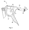
- This in Fig. 1 shown in a simplified section printing, especially gravure printing comprises a rotating body 01, z.
- a roller 01 or a cylinder 01 in particular a forme cylinder 01, a paint tray 02, in which the forme cylinder dips 01 and from which he takes color in its rotation, a pressure roller 03, in a conventional manner as a with an elastic Material such as rubber coated, rotatable cylinder 03 is executed, and a squeegee 04, short squeegee 04.
- the doctor 04 is, based on the direction of rotation of the forme cylinder 01 in the counterclockwise direction in the Fig. 1 , arranged on the way from the ink tray 02 to a printing gap formed between the forme cylinder 01 and impression roller 03, through which a web 06 to be printed, in particular a material web 06, is guided.
- the squeegee 04 has a hollow interior 07 which extends over its entire length and can be acted upon by compressed air through a connection piece 05 attached to a rear side.
- the interior 07 is bounded by dense sheets, the surface facing the forme cylinder 01, at least in the cooperating with the forme cylinder 01 area a plurality of openings 10, in particular micro-openings 10 (see Fig. 2 ), through which in operation from the interior 07, z. B. cavity 07, in particular designed as a pressure chamber 07 chamber 07, under pressure against the environment fluid standing, z.
- a liquid, a gas or a mixture, in particular air flows.
- a corresponding supply of compressed air into the cavity 07 is not shown.
- micro-openings 10 are these as open pores on the surface of a porous, especially microporous, air-permeable material 09, z. B. of an open-pore sintered material 09, in particular of sintered metal 09, is formed.
- the pores of the air-permeable porous material 09 have a mean diameter (average size) of less than 150 microns, z. B. 5 to 50 microns, in particular 10 - 30 microns.
- the material 09 has an irregular, formed amorphous structure.
- the cavity 07 of the doctor blade 04 can, at least on its area cooperating with the forme cylinder 01, be formed substantially solely from a body of porous solid material closing the cavity 07 on this side (that is to say without further load-bearing layers of corresponding thickness).
- This substantially self-supporting body is then formed with a wall thickness of greater than or equal to 2 mm, in particular greater than or equal to 3 mm.
- Such a carrier body 08 can be acted upon with compressed air, which flows out of the carrier body 08 through the microporous layer 09 and thus forms an air cushion on the surface of the squeegee 04.
- the porous material 09 is thus not designed as a load-bearing solid body (with or without frame construction), but as a coating 09 on a feedthroughs 15 or passage openings, in particular metallic, carrier material.
- non-supporting layer 09 in conjunction with the support body 08 is understood - in contrast to, for example, known from the prior art "supporting" layers - a structure, wherein the layer 09 over its entire layer length and total layer width each on a plurality of nodes the support body 08 is supported.
- the carrier body 08 has z. B. on its co-operating with the layer 09 width and length respectively a plurality of non-contiguous passages 15, z. B. holes 15, on.
- This embodiment is distinctly different from a design in which a porous material extending over the entire active surface is self-supporting over this distance is supported only in one end to a frame or carrier, and therefore must have a corresponding strength.
- the carrier material essentially absorbs the weight, shear, torsional, bending and / or shearing forces of the doctor, which is why a corresponding wall thickness (eg greater than 3 mm, in particular greater than 5 mm) of the carrier body 08 and / or a suitably stiffened construction is selected.
- the porous material 09 outside the bushing 15 has z. B. a layer thickness which is smaller than 1 mm, on. Particularly advantageous is a layer thickness between 0.05 mm and 0.3 mm.
- a proportion of open area in the region of the effective outer surface of the porous material 09 is between 3% and 30%, preferably between 10% and 25%.
- opening degree is between 3% and 30%, preferably between 10% and 25%.
- the thickness of the layer 09 at least equal to the distance between adjacent openings of the bores 15 of the support body 08.
- the first embodiment ( Fig. 2 ) is the interior 07 on the side facing the forme cylinder 01, at least in the region of a metering edge 11, bounded by the multiple perforated support body 08 or the multiple perforated wall 12. This or this carries on its or its outside the layer 09 of microporous material 09.
- the carrier body 08 may be a multi-perforated piece of flat material or molded material such as a stamped sheet or a rigid wire mesh; but is also possible a three-dimensional air-permeable body such as an open-cell metal foam, etc.
- the openings are shown as the cavity 07 with the layer 09 connecting holes 15.
- Choice of material, dimensioning and pressurization are selected such that 1 to 20 standard cubic meters per m 2 , in particular 2 to 15 standard cubic meters per m 2 , emerge from the air outlet surface of the sintered material 09 per hour. Particularly advantageous is the Air outlet from 3 to 7 standard cubic meters per m 2 .
- the forme cylinder 01 facing side of the doctor blade 04 has the metering edge 11 which can be adjusted to the surface of the forme cylinder 01 with an adjustable gap width, and between the metering edge 11 and the ink pan 02 a continuous sloping wall 12 extending into one Paint tray 02 surrounding collecting container 13 extends into and on which by the metering edge 11 from the surface of the forme cylinder 01 stripped paint can flow into the collecting container 13.
- the perforated carrier body 08 extends into the metering edge 11, so that compressed air can penetrate from the inner space 07 to the metering edge 11 and can escape via the metering edge 11 uniformly with a small layer thickness microporous layer 09.
- the metering edge 11 and mounted on the forme cylinder 01 printing plates or rasterized in form cylinder 01 are practically free of fretting, while the action of the doctor 04 is practically the same as in a conventional squeegee with fixed or flexible lips.
- the microporous layer 09 which covers the carrier body 08, be flowed through homogeneously by air. This prevents color stripped off by the metering edge 11 from collecting on the wall 12 and leading to a jam in front of the metering edge 11. Even if the color used is highly viscous, it can Do not wet the wall 12 and roll it off drop by drop.
- the required throughput of compressed air per unit area of the wall 12 is less than that required in the amount of the metering edge 11.
- Such different flow rates can be realized by the number of holes 15 and their relative cross-sectional area in the support body 08 and the thickness of the microporous layer 09 and the porosity of the layer 09 are each selected suitably. That is, in the region of the metering edge 11, the density of the bores 15 (hole density) must be greater and / or the thickness of the layer 09 must be smaller than in the region of the wall 12.
- a regulation is also possible via the amount of air and / or the air pressure.
- Air that has passed through one of the bores 15 of the support body 08 tends to distribute in the pores of the microporous layer 09 both to the surface thereof and sideways, parallel to the surface. Assuming that the flow resistance in the microporous layer 09 is isotropic, the air which has passed through a bore 15 of the support body 08 is also isotropically distributed in the layer 09. In order to provide a homogeneous, gapless air cushion on the surface of the layer 09, Air must escape on its entire surface, even in those areas under which there is an impermeable surface area of the support body 08. For this purpose, the thickness of the microporous layer 09 may be at least as great as an average distance between adjacent bores 15 on the surface of the carrier body 08.
- the wall thickness of the support body 08 at least in the layer 09 supporting area is z. B. greater than 3 mm, in particular greater than 5 mm.
- the support body 08 may in turn also made of porous material, but with a better air permeability -. B. a larger pore size - be designed as that of the microporous material of the layer 09.
- the carrier body 08 can also be formed from any desired cavity enclosing the cavity 07, provided with passages 15 flat material or molded material. Combinations of these alternatives are also possible.
- the inner cross section of a feed line, not shown, for supplying the compressed air to the turning bar is less than 100 mm 2 , preferably between 10 and 60 mm 2 .
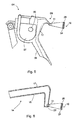
- Fig. 3 shows a second embodiment with a relative to the squeegee 04 modified doctor device 14, z. B. squeegee 14.
- the tip of the squeegee 14 is in Fig. 4 shown in section on an enlarged scale.
- a housing of the doctor blade 14 is formed by an angularly bent inner plate 16 and an approximately parallel thereto extending outer plate 17, which is often broken at one of the forme cylinder 01 facing end side 18 and adjacent to the inner panel 16 bottom 19.
- the doctor blade 14 is provided to be employed with its limited by front side 18 and bottom 19 edge 22 against the forme cylinder 01.
- Size, cross-sectional area and density of the bore 21, z. B. perforations 21 in the region of the effective edge 22 as dosing edge 22 are set so that, as in the case of Fig. 1 and 2 a homogeneous air cushion between the edge 22 and the surface of the forme cylinder 01 is formed, which prevents direct contact of the squeegee 14 with the forme cylinder 01.
- the density and / or cross-sectional area of the bores 21 is greater, smaller or equal than in the region of the edge 22, so that here an intense air flow emerges, the color stripped from the forme cylinder 01 by the edge 22 deviates from the underside 19.
- a collecting screen 23 is arranged, which is struck by thrown-off paint drops and on which they can flow down.
- the collecting screen 23 may also have a surface of air-flowed microporous material 09 facing the forme cylinder 01 on a perforated support 08 corresponding to the wall 12 of the squeegee 04 Fig. 1 to have.
- FIGS. 5 and 6 for the micro-openings 03 these are designed as openings through-holes 24, in particular micro holes 24, which are characterized by a z. B. formed as a pressure chamber 07 cavity 07 limiting wall 26, z. B. chamber wall 26, extend outward.
- the holes 24 have z. B. a diameter (at least in the region of the openings 10) of less than or equal to 500 .mu.m, advantageously less than or equal to 300 .mu.m, in particular between 60 and 150 .mu.m.
- the opening degree is z. B. at 3 to 25%, especially at 5 to 15%.
- a hole density is at least 1/5 mm 2 , in particular at least 1 / mm 2 up to 4 / mm 2 .
- the wall 26 thus has, at least in a region opposite the forme cylinder 01, a microperforation.
- the microperforation extends - as in the first embodiment, the bushings 15 and layer 09 - at least in the effective range between doctor 04 and forme cylinder 01st
- One of the flow resistance influencing wall thickness of the holes 24 containing chamber wall 26 is z. B. at 0.2 to 3.0 mm, advantageously at 0.2 to 1.5 mm. in particular from 0.3 to 0.8 mm.
- a reinforcing construction not shown, for example, in the longitudinal direction of the squeegee 04 extending support, in particular metal support, may be arranged on which the chamber wall 26 at least partially or selectively supported.
- Fig. 6 is the second embodiment of the squeegee 04 off Fig. 3 in the version with microbores 24 off Fig. 5 shown.
- the bores 24 may be cylindrical, funnel-shaped or else of a special shape (for example in the form of a Laval nozzle).
- the microperforation, d. H. the bores 24 are preferably produced by drilling by means of accelerated particles (eg liquid such as water jet, ions or elementary particles) or by means of electromagnetic radiation of high energy density (for example light by means of a laser beam). Particularly advantageous is the production by means of electron beam.
- accelerated particles eg liquid such as water jet, ions or elementary particles
- electromagnetic radiation of high energy density for example light by means of a laser beam
- the forme cylinder 01 facing side of the holes 24 having wall 26, z.
- a wall 26 formed of stainless steel in an advantageous embodiment, a dirt and / or color-repellent finish. It has a not shown, the openings 10 and bores 24 not covering coating -.
- the holes having the wall is formed in a variant as one or more inserts in a carrier.
- the insert may be fixed or changeable connected to the carrier. The latter is advantageous in terms of cleaning or exchanging inserts of different types of microperforations for adaptation to different colors, printing forms, etc.
Landscapes
- Mechanical Engineering (AREA)
- Engineering & Computer Science (AREA)
- Registering, Tensioning, Guiding Webs, And Rollers Therefor (AREA)
- Folding Of Thin Sheet-Like Materials, Special Discharging Devices, And Others (AREA)
- Absorbent Articles And Supports Therefor (AREA)
- Coating Apparatus (AREA)
- Advancing Webs (AREA)
- Acyclic And Carbocyclic Compounds In Medicinal Compositions (AREA)
- Paper (AREA)
- Controlling Rewinding, Feeding, Winding, Or Abnormalities Of Webs (AREA)
- Printers Or Recording Devices Using Electromagnetic And Radiation Means (AREA)
- Accessory Devices And Overall Control Thereof (AREA)
- Coating With Molten Metal (AREA)
- Cleaning By Liquid Or Steam (AREA)
- Cleaning And De-Greasing Of Metallic Materials By Chemical Methods (AREA)
- Materials For Medical Uses (AREA)
- Rotary Presses (AREA)
- Piezo-Electric Or Mechanical Vibrators, Or Delay Or Filter Circuits (AREA)
- Handling Of Sheets (AREA)
- Lead Frames For Integrated Circuits (AREA)
- Saccharide Compounds (AREA)
- Enzymes And Modification Thereof (AREA)
- Media Introduction/Drainage Providing Device (AREA)
- Control Of Electric Motors In General (AREA)
- Devices For Checking Fares Or Tickets At Control Points (AREA)
- Electronic Switches (AREA)
- Forging (AREA)
- Formation And Processing Of Food Products (AREA)
- Physical Or Chemical Processes And Apparatus (AREA)
- Bridges Or Land Bridges (AREA)
- Electrical Discharge Machining, Electrochemical Machining, And Combined Machining (AREA)
- Dental Preparations (AREA)
- Safety Valves (AREA)
- Feeding Of Articles By Means Other Than Belts Or Rollers (AREA)
- Containers And Plastic Fillers For Packaging (AREA)
- Yarns And Mechanical Finishing Of Yarns Or Ropes (AREA)
- Filtering Materials (AREA)
Claims (32)
- Dispositif de racle (04 ; 14) d'une machine d'impression présentant une arête de dosage (11 ; 22), qui peut être placé sur un corps de rotation (01) coopérant, caractérisé en ce que le dispositif de racle (04) présente au moins dans la zone de son arête de dosage (11 ; 22) une pluralité d'ouvertures (10) pour la sortie d'un fluide gazeux mis sous pression, qui forme pendant le service un matelas gazeux entre l'arête de dosage (11 ; 22) et une surface du corps de rotation (01).
- Dispositif de racle (04 ; 14) d'une machine d'impression comprenant une arête de dosage (11 ; 22), qui est placé sur un corps de rotation (01) coopérant, caractérisé en ce que le dispositif de racle (04 ; 14) présente au moins dans la zone de son arête de dosage (11 ; 22) du matériau (09) microporeux et perméable à l'air, dont les pores présentent un diamètre moyen de 5 à 50 µm.
- Dispositif de racle selon la revendication 2, caractérisé en ce que le matériau (09) microporeux présente sur sa face extérieure une pluralité d'ouvertures (10) pour la sortie d'un fluide gazeux mis sous pression, qui forme pendant le service un matelas gazeux entre l'arête de dosage (11 ; 22) et une surface du corps de rotation (01).
- Dispositif de racle selon la revendication 1 ou 3, caractérisé en ce que les ouvertures (10) sont réalisées sous forme de micro-ouvertures (10) avec un diamètre inférieur à 500 µm.
- Dispositif de racle selon la revendication 1, caractérisé en ce que les ouvertures (03) sont réalisées sous forme de pores ouverts d'un matériau (09) poreux traversé par le fluide.
- Dispositif de racle selon la revendication 5, caractérisé en ce que les pores du matériau (09) poreux et perméable au fluide présentent un diamètre moyen de 5 à 50 µm, en particulier de 10 à 30 µm.
- Dispositif de racle selon la revendication 2 ou 5, caractérisé en ce que le matériau (09) poreux est conçu sous forme de matériau fritté (09) à pores ouverts, en particulier sous forme de métal fritté (09).
- Dispositif de racle selon la revendication 2 ou 5, caractérisé en ce qu'un degré d'ouverture sur la surface dirigée vers l'extérieur du matériau (09) poreux se situe entre 3 à 30 %, de préférence entre 10 % et 25 %.
- Dispositif de racle selon la revendication 2 ou 5, caractérisé en ce que le matériau (09) microporeux est réalisé sous forme de couche (09) sur un support (08) portant une charge, mais au moins par endroits perméable au fluide.
- Dispositif de racle selon la revendication 9, caractérisé en ce que le support (08) présente sur son côté tourné vers la couche (09) au moins une face porteuse reliée à la couche (09) et une pluralité d'ouvertures pour l'arrivée du fluide dans la couche (09).
- Dispositif de racle selon la revendication 10, caractérisé en ce que la couche (09) présente dans la zone de la face porteuse une épaisseur inférieure à 1 mm en particulier de 0,05 mm à 0,3 mm.
- Dispositif de racle selon la revendication 9, caractérisé en ce que le support (08) présente sur sa largeur et longueur coopérant avec la couche (06) à chaque fois une pluralité de passages (15), en particulier non communicants.
- Dispositif de racle selon la revendication 9, caractérisé en ce qu'une épaisseur de paroi du support (08) ou au moins de la paroi portant la couche (09) est supérieure à 3 mm, en particulier supérieure à 5 mm.
- Dispositif de racle selon la revendication 9, caractérisé en ce que le support (08) est formé au moins en partie avec un matériau (09) poreux présentant une meilleure perméabilité à l'air que le matériau (09) microporeux.
- Dispositif de racle selon la revendication 9, caractérisé en ce que le support (08) est formé au moins en partie à base d'un matériau plat entourant une cavité (07) et doté d'ouvertures.
- Dispositif de racle selon la revendication 9, caractérisé en ce que le support (09) microporeux présente une épaisseur de couche qui correspond au moins à l'espacement d'ouvertures voisines du support (08).
- Dispositif de racle selon la revendication 9, caractérisé en ce que le support (08) simule le contour extérieur de l'arête de dosage (11).
- Dispositif de racle selon la revendication 1, caractérisé en ce que les ouvertures (10) sont réalisées sous forme d'ouvertures (10) dirigées vers l'extérieur de microalésages (24) dans une paroi (26) délimitant le racle (04) vers l'extérieur en direction du corps de rotation (01).
- Dispositif de racle selon la revendication 18, caractérisé en ce qu'un diamètre des ouvertures (10) est inférieur ou égal à 300 µm, en particulier entre 60 et 150 µm.
- Dispositif de racle selon la revendication 18, caractérisé en ce qu'une épaisseur de paroi de la paroi (26) se situe entre 0,2 et 3,0 mm.
- Dispositif de racle selon la revendication 18, caractérisé en ce qu'une densité de trou, c'est-à-dire un nombre d'ouvertures (10) par unité de surface, pour la surface dotée des microalésages (10) est d'au moins 0,2 /mm2.
- Dispositif de racle selon la revendication 1 ou 6, caractérisé en ce que 1 à 20 mètres étalon d'air par heure sortent sur un mètre carré de la surface d'enveloppe présentant les ouvertures (10).
- Dispositif de racle selon la revendication 1 ou 3, caractérisé en ce que 2 à 15, en particulier 3 à 7, mètres cubes étalon d'air par heure sortent sur un mètre carré de la surface d'enveloppe présentant les ouvertures (03) .
- Dispositif de racle selon la revendication 2 ou 5, caractérisé en ce que le matériau (06) poreux est sollicité par l'intérieur avec au moins 1 bar de surpression.
- Dispositif de racle selon la revendication 2 ou 5, caractérisé en ce que le matériau (06) poreux est sollicité par l'intérieur avec plus de 4 bars, en particulier avec 5 à 7 bars, de surpression avec le fluide.
- Dispositif de racle selon la revendication 1 ou 3, caractérisé en ce qu'une conduite pour l'arrivée de fluide à l'élément directeur (01) présente une section intérieure inférieure à 100 mm2, en particulier comprise entre 10 et 60 mm2.
- Dispositif de racle selon la revendication 1 ou 3, caractérisé en ce que le fluide mis sous pression est réalisé sous forme d'air comprimé.
- Dispositif de racle selon la revendication 1 ou 3, caractérisé en ce que la partie, portant les ouvertures (10), de la racle (04) est réalisée sous forme d'insert amovible sur un support.
- Dispositif de racle selon la revendication 1 ou 3, caractérisé en ce qu'une paroi (12) du composant (04), qui avance de l'arête de dosage (11), présente également des ouvertures (10) pour la sortie du fluide.
- Dispositif de racle selon les revendications 18 et 25, caractérisé en ce que la paroi (12) est formée également par le support (08) revêtu avec le matériau (09) microporeux.
- Dispositif de racle selon la revendication 1 ou 3 et la revendication 25, caractérisé en ce que la perméabilité au fluide par unité de surface sur l'arête de dosage (11) est supérieure à celle sur la paroi (12).
- Dispositif de racle selon la revendication 1, 3 ou 25, caractérisé en ce qu'une région de perméabilité au fluide maximale est présente sur un côté (19), tourné vers un récipient collecteur d'encre, de l'arête de dosage (11).
Applications Claiming Priority (9)
| Application Number | Priority Date | Filing Date | Title |
|---|---|---|---|
| DE10248820 | 2002-10-19 | ||
| DE10248820 | 2002-10-19 | ||
| DE10307089A DE10307089B4 (de) | 2002-10-19 | 2003-02-19 | Rakel einer Druckmaschine |
| DE10307089 | 2003-02-19 | ||
| DE10322651 | 2003-05-20 | ||
| DE10322651 | 2003-05-20 | ||
| DE10331469 | 2003-07-11 | ||
| DE10331469 | 2003-07-11 | ||
| PCT/DE2003/003471 WO2004037539A2 (fr) | 2002-10-19 | 2003-10-20 | Systemes de racle pour machine de production ou de traitement de bandes de matiere |
Publications (2)
| Publication Number | Publication Date |
|---|---|
| EP1556218A2 EP1556218A2 (fr) | 2005-07-27 |
| EP1556218B1 true EP1556218B1 (fr) | 2008-05-21 |
Family
ID=32180556
Family Applications (8)
| Application Number | Title | Priority Date | Filing Date |
|---|---|---|---|
| EP08161186A Expired - Lifetime EP1997759B1 (fr) | 2002-10-19 | 2003-10-20 | Elément de guidage d'une machine de production et de traitement d'une bande |
| EP06100923A Expired - Lifetime EP1655257B1 (fr) | 2002-10-19 | 2003-10-20 | Appareil de pliage |
| EP03778236A Expired - Lifetime EP1556218B1 (fr) | 2002-10-19 | 2003-10-20 | Systemes de racle pour machine de production ou de traitement de bandes de matiere |
| EP03776806A Expired - Lifetime EP1556219B1 (fr) | 2002-10-19 | 2003-10-20 | Elements de guidage pour unite d'impression |
| EP03776804A Expired - Lifetime EP1554208B1 (fr) | 2002-10-19 | 2003-10-20 | Cone plieur pour machine de production ou de traitement de bandes de matiere |
| EP03776807A Expired - Lifetime EP1556300B1 (fr) | 2002-10-19 | 2003-10-20 | Elements de guidage de machine de production ou de traitement de bandes de matiere |
| EP03776805A Expired - Lifetime EP1554122B1 (fr) | 2002-10-19 | 2003-10-20 | Elements de compression pour une machine d'impression de traitement de bandes de matiere |
| EP03776803A Expired - Lifetime EP1554207B1 (fr) | 2002-10-19 | 2003-10-20 | Appareil de pliage |
Family Applications Before (2)
| Application Number | Title | Priority Date | Filing Date |
|---|---|---|---|
| EP08161186A Expired - Lifetime EP1997759B1 (fr) | 2002-10-19 | 2003-10-20 | Elément de guidage d'une machine de production et de traitement d'une bande |
| EP06100923A Expired - Lifetime EP1655257B1 (fr) | 2002-10-19 | 2003-10-20 | Appareil de pliage |
Family Applications After (5)
| Application Number | Title | Priority Date | Filing Date |
|---|---|---|---|
| EP03776806A Expired - Lifetime EP1556219B1 (fr) | 2002-10-19 | 2003-10-20 | Elements de guidage pour unite d'impression |
| EP03776804A Expired - Lifetime EP1554208B1 (fr) | 2002-10-19 | 2003-10-20 | Cone plieur pour machine de production ou de traitement de bandes de matiere |
| EP03776807A Expired - Lifetime EP1556300B1 (fr) | 2002-10-19 | 2003-10-20 | Elements de guidage de machine de production ou de traitement de bandes de matiere |
| EP03776805A Expired - Lifetime EP1554122B1 (fr) | 2002-10-19 | 2003-10-20 | Elements de compression pour une machine d'impression de traitement de bandes de matiere |
| EP03776803A Expired - Lifetime EP1554207B1 (fr) | 2002-10-19 | 2003-10-20 | Appareil de pliage |
Country Status (9)
| Country | Link |
|---|---|
| US (3) | US7383772B2 (fr) |
| EP (8) | EP1997759B1 (fr) |
| JP (1) | JP2006502937A (fr) |
| CN (2) | CN100551798C (fr) |
| AT (8) | ATE390280T1 (fr) |
| AU (6) | AU2003286098A1 (fr) |
| DE (8) | DE20380219U1 (fr) |
| ES (2) | ES2306904T3 (fr) |
| WO (6) | WO2004037698A1 (fr) |
Families Citing this family (34)
| Publication number | Priority date | Publication date | Assignee | Title |
|---|---|---|---|---|
| DE10339262A1 (de) * | 2003-08-26 | 2005-03-17 | Voith Paper Patent Gmbh | Bahnführungseinrichtung |
| US7921771B2 (en) | 2004-06-23 | 2011-04-12 | Koenig & Bauer Aktiengesellschaft | Web-fed printing machine having a turning bar |
| US7311234B2 (en) * | 2005-06-06 | 2007-12-25 | The Procter & Gamble Company | Vectored air web handling apparatus |
| DE102006013954B4 (de) | 2006-03-27 | 2008-03-06 | Koenig & Bauer Aktiengesellschaft | Druckmaschine mit einer Einrichtung zum Zuführen einer Materialbahn |
| DE102006013955B3 (de) | 2006-03-27 | 2007-10-31 | Koenig & Bauer Aktiengesellschaft | Einrichtungen zum Zuführen einer Materialbahn zu einer Druckeinheit |
| DE102006013956B4 (de) | 2006-03-27 | 2008-02-07 | Koenig & Bauer Aktiengesellschaft | Druckmaschine mit einer Einrichtung zum Zuführen einer Materialbahn und ein Verfahren zum Zuführen einer Materialbahn |
| EP2148779B1 (fr) * | 2007-05-21 | 2014-01-15 | Koenig & Bauer Aktiengesellschaft | Procédés et dispositif pour produire une section de produit dans une machine de traitement de bande |
| DE102007000507B4 (de) | 2007-10-15 | 2010-03-11 | Koenig & Bauer Aktiengesellschaft | Walze eines Trockners |
| DE102007000508B4 (de) | 2007-10-15 | 2011-09-15 | Koenig & Bauer Aktiengesellschaft | Trockner für mindestens eine Materialbahn |
| DE102008041424A1 (de) * | 2008-08-21 | 2010-02-25 | Voith Patent Gmbh | Vorrichtung und Verfahren zur Verarbeitung einer laufenden Materialbahn |
| TWI349644B (en) * | 2008-09-18 | 2011-10-01 | Ind Tech Res Inst | Suction roller and transporting apparatus using the same |
| TWI367855B (en) * | 2008-09-24 | 2012-07-11 | Apparatus and method for guiding the web position | |
| CN102177023A (zh) * | 2008-10-10 | 2011-09-07 | 惠普开发有限公司 | 自动清理空气惰轮 |
| DE102009002103B4 (de) | 2009-04-01 | 2011-07-07 | KOENIG & BAUER Aktiengesellschaft, 97080 | Druckmaschine und ein Verfahren zum Bedrucken eines bahnförmigen Bedruckstoffs |
| DE102009026059B4 (de) * | 2009-06-29 | 2024-02-01 | Krones Aktiengesellschaft | Vorrichtung zum Aufspreizen einer Folienbahn |
| DE202010005837U1 (de) | 2010-04-16 | 2010-07-29 | Prospective Concepts Ag | Leitelement einer bahnerzeugenden oder -verarbeitenden Maschine |
| EP2502725B1 (fr) * | 2011-03-24 | 2015-01-07 | PackSys Global (Switzerland) Ltd. | Dispositif et procédé de fabrication de corps tubulaires |
| DE102011106695A1 (de) * | 2011-07-06 | 2013-01-10 | Multivac Sepp Haggenmüller Gmbh & Co. Kg | Verfahren und Vorrichtung zum Heizen einer Folie |
| ES2563647T3 (es) * | 2011-08-22 | 2016-03-15 | Windmöller & Hölscher Kg | Máquina y procedimiento de impresión de bandas de material |
| DE102011117494A1 (de) * | 2011-10-31 | 2013-05-02 | Eastman Kodak Company | Vorrichtung und Verfahren zum Bedrucken einer Substratbahn |
| US20130256362A1 (en) * | 2012-03-30 | 2013-10-03 | Michael T. Dobbertin | Replaceable cover for bars in a printing system |
| CN103434887B (zh) * | 2013-08-30 | 2015-09-02 | 无锡宝南机器制造有限公司 | 三角板移动调节机构 |
| CN103569776A (zh) * | 2013-11-06 | 2014-02-12 | 北京印刷学院 | 一种折页三角板装置 |
| CN104609246A (zh) * | 2015-01-16 | 2015-05-13 | 常州市永明机械制造有限公司 | 复膜机折幅布面展平装置 |
| CN105035839A (zh) * | 2015-06-15 | 2015-11-11 | 青岛正大环保科技有限公司 | 薄膜多级对折器 |
| GB2560194B (en) * | 2017-03-03 | 2021-03-31 | Kingspan Holdings Irl Ltd | Process and apparatus for producing shaped profile sections |
| CN107095740A (zh) * | 2017-03-21 | 2017-08-29 | 泉州市汉威机械制造有限公司 | 一种一次性用品折叠机构 |
| JP6527981B1 (ja) * | 2018-03-27 | 2019-06-12 | 株式会社タンケンシールセーコウ | ターンバー |
| EP3894363A2 (fr) * | 2018-12-13 | 2021-10-20 | Corning Incorporated | Appareil de transport et procédés de transport de ruban |
| TW202100832A (zh) * | 2019-03-11 | 2021-01-01 | 以色列商核心流有限公司 | 用於卷對卷製程之流體流腹板張力裝置 |
| IT201900003553A1 (it) * | 2019-03-12 | 2020-09-12 | Gtk Timek Group Sa | "barra di movimentazione di supporti laminati o in film" |
| CN111016408A (zh) * | 2019-12-31 | 2020-04-17 | 江苏斯派尔建材科技有限公司 | 一种新型金属木纹保温装饰一体板印花系统 |
| DE102021103766A1 (de) | 2021-02-17 | 2022-08-18 | Manroland Goss Web Systems Gmbh | Trichternase und Falztrichter |
| US20230129901A1 (en) * | 2021-10-21 | 2023-04-27 | Gerhard Designing & Manufacturing Inc. | Excess coating removal device for can coating machines |
Family Cites Families (91)
| Publication number | Priority date | Publication date | Assignee | Title |
|---|---|---|---|---|
| GB794404A (en) * | 1956-09-01 | 1958-05-07 | Richard Kurt Sinejda | Multi-colour attachment to the print roller in roller printing |
| US3097971A (en) * | 1960-11-09 | 1963-07-16 | British Iron Steel Research | Method of and apparatus for supporting or guiding strip material |
| DE1142878B (de) | 1961-01-28 | 1963-01-31 | Maschf Augsburg Nuernberg Ag | Falztrichter zum Laengsfalzen von in Rotationsdruckmaschinen verarbeiteten Papierbahnen |
| US3111310A (en) * | 1961-12-21 | 1963-11-19 | Orville V Dutro | Folder |
| US3245334A (en) * | 1962-08-27 | 1966-04-12 | Du Pont | Noncontacting sealing method and apparatus |
| US3518940A (en) | 1967-06-30 | 1970-07-07 | Cameron Machine Co | Endless belt printing machine |
| DE1954316A1 (de) * | 1969-10-29 | 1971-05-19 | Schluckebier Wilhelm | Verfahren und Einrichtung zum Beschicken von Walzen in Druckwerken von Druckmaschinen mit einem fluessigen Medium,z.B. Farbe,und zum Dosieren des Mediums |
| DE2026355B1 (de) * | 1970-05-29 | 1971-11-18 | Roland Offsetmaschinenfabrik Faber & Schleicher Ag, 6050 Offenbach | Wendestange zum Umlenken von Papierbahnen |
| DE2142902A1 (de) * | 1971-08-27 | 1973-03-08 | Dornier Ag | Vorrichtung zum schneiden, sammeln und falzen einer oder mehrerer ankommender papierbahnen |
| DE2215523A1 (de) | 1972-03-30 | 1973-10-04 | Anger Kunststoff | Ueberdruckkalibrierduesen und kuehlvorrichtung |
| DE2215532B2 (de) * | 1972-03-30 | 1976-01-02 | Saueressig Gmbh, 4422 Ahaus | Walzendruckmaschine zum mehrfarbigen Bedrucken von Warenbahnen |
| US4035878A (en) * | 1974-11-06 | 1977-07-19 | Sw (Delaware), Inc. | Apparatus for smoothing the surfaces of moving webs |
| US4221596A (en) * | 1976-10-04 | 1980-09-09 | General Motors Corporation | Method for low pressure forming of fused silica compositions and resultant bodies |
| US4176775A (en) * | 1977-03-28 | 1979-12-04 | Beloit Corporation | Inhibiting noise in sheet spreaders |
| FR2456695A1 (fr) * | 1979-02-13 | 1980-12-12 | Pliage Service | Collage en vue de scellage de depliants publicitaires croises |
| DE2921757A1 (de) | 1979-05-29 | 1980-12-04 | Maschf Augsburg Nuernberg Ag | Verfahren zum herstellen eines trichterbleches fuer einen falztrichter einer rotationsdruckmaschine und danach hergestelltes trichterblech |
| DE2931968B1 (de) * | 1979-08-07 | 1981-07-16 | Heidelberger Druckmaschinen Ag, 6900 Heidelberg | Falzapparat an Rollen-Rotationsdruckmaschinen |
| DD152754A1 (de) * | 1980-08-29 | 1981-12-09 | Dietrich Hank | Luftumspuelte wendestange,insbes.fuer die richtungsaenderung laufender materialbahnen |
| US4361089A (en) * | 1980-10-20 | 1982-11-30 | Magna-Graphics Corporation | Multi-color rotary press |
| JPS57167330A (en) | 1981-04-09 | 1982-10-15 | Asahi Chem Ind Co Ltd | Material for sintered body |
| DE3127872C2 (de) | 1981-07-15 | 1985-11-28 | M.A.N.- Roland Druckmaschinen AG, 6050 Offenbach | Wendestangenwagen |
| US4416201A (en) | 1981-11-18 | 1983-11-22 | Monarch Marking Systems, Inc. | Ink roller assembly with capillary ink supply |
| DE3212826A1 (de) | 1982-04-06 | 1983-10-13 | Deilmann-Haniel GmbH, 4600 Dortmund | Bremsvorrichtung fuer foerdermaschinen, haspel und widen |
| DE3225360A1 (de) * | 1982-07-07 | 1984-02-09 | M.A.N.- Roland Druckmaschinen AG, 6050 Offenbach | Rollenoffset-rotationsdruckmaschine |
| JPS59192571A (ja) | 1983-04-18 | 1984-10-31 | Toray Ind Inc | 凹版印刷版使い印刷用ドクタ− |
| JPS6112396A (ja) | 1984-06-29 | 1986-01-20 | Toray Ind Inc | ドクタ−ブレ−ド |
| US4701233A (en) * | 1986-01-16 | 1987-10-20 | Pitney Bowes Inc. | Method for folding and sealing sheets |
| FR2598962B1 (fr) * | 1986-05-21 | 1988-12-23 | Prepac Sarl | Conformateur de film souple equipe d'embouts en saillie |
| ES2031187T3 (es) * | 1987-09-11 | 1992-12-01 | M.A.N.-Roland Druckmaschinen Aktiengesellschaft | Dispositivo en maquinas rotativas en impresion de pliegos en varios colores para apretar un pliego sobre el cilindro de impresion. |
| US4957045A (en) * | 1988-04-16 | 1990-09-18 | Elmar Messerschmitt | Doctor for screen printing |
| US5031528A (en) * | 1988-04-16 | 1991-07-16 | Elmar Messerschmitt | Doctor for screen printing |
| US4865578A (en) * | 1988-05-16 | 1989-09-12 | Moll Richard J | Glue head mounting bracket for glue applying folding machines |
| US4925080A (en) * | 1988-10-13 | 1990-05-15 | Beloit Corporation | Spreader bar apparatus |
| DE3939501A1 (de) * | 1989-11-30 | 1991-06-06 | Convac Gmbh | Laminar-beschichtungsvorrichtung fuer ebene substrate |
| US5082533A (en) * | 1990-04-10 | 1992-01-21 | Beloit Corporation | Heated extended nip press with porous roll layers |
| WO1991017943A1 (fr) | 1990-05-11 | 1991-11-28 | Liedtke Rudolph J | Coussinet d'air pour materiau en bande |
| DE4127602A1 (de) * | 1991-08-21 | 1993-02-25 | Hoechst Ag | Verfahren und vorrichtung zum beruehrungsfreien fuehren eines beschichteten materialbandes |
| DE4200769C1 (fr) | 1992-01-14 | 1993-07-22 | Maschinenfabrik Wifag, Bern, Ch | |
| US5850788A (en) * | 1992-01-14 | 1998-12-22 | Maschinenfabrik Wifag | Metering strip |
| FI87669C (fi) * | 1992-03-02 | 1993-02-10 | Valmet Paper Machinery Inc | Foerfarande och tork vid torkning av papper |
| JPH0639991A (ja) | 1992-07-22 | 1994-02-15 | Mitsubishi Heavy Ind Ltd | 掻き取りブレード |
| US5316199A (en) | 1992-09-18 | 1994-05-31 | Rockwell International Corporation | Adjustable angle bar assembly for a printing press |
| DE4234307A1 (de) * | 1992-10-12 | 1994-04-14 | Heidelberger Druckmasch Ag | Einrichtung zur störungsfreien Produktförderung in Falzapparaten |
| JP3111721B2 (ja) | 1993-01-07 | 2000-11-27 | 東洋インキ製造株式会社 | 進行ウエブの転換方法 |
| US5505042A (en) * | 1993-03-29 | 1996-04-09 | Liberty Industries | Air assisted feed through conveyor for rotary film wrapping apparatus |
| DE9320281U1 (de) | 1993-04-07 | 1994-03-17 | Koenig & Bauer Ag | Wendestange für eine Materialbahn |
| DE4311438C2 (de) * | 1993-04-07 | 1997-06-19 | Koenig & Bauer Albert Ag | Wendestange für eine Materialbahn |
| JP2801519B2 (ja) | 1993-04-08 | 1998-09-21 | ゴス グラフイック システムズ インコーポレイテッド | 印刷機用の幅調整可能なアングルバー組立体 |
| DE9311113U1 (de) | 1993-07-26 | 1993-09-09 | Zirkon Druckmaschinen Gmbh | Eindruckwerk für fliegend wechselnde Eindrucke |
| JP3060791B2 (ja) * | 1993-08-10 | 2000-07-10 | 東洋インキ製造株式会社 | 進行ウエブの転換方法 |
| DE4330681A1 (de) | 1993-09-10 | 1995-03-16 | Roland Man Druckmasch | Kammerrakel |
| DE4335473C2 (de) * | 1993-10-18 | 2001-07-12 | Oce Printing Systems Gmbh | Wendeeinrichtung für einen bandförmigen Aufzeichnungsträger |
| DE4410189A1 (de) * | 1994-03-24 | 1995-09-28 | Heidelberger Druckmasch Ag | Leiteinrichtung für bewegtes Bogenmatrial in Druckmaschinen |
| DE4435528C2 (de) | 1994-10-05 | 1997-09-04 | Roland Man Druckmasch | Falztrichter für eine Druckmaschine |
| EP0705785A3 (fr) * | 1994-10-07 | 1996-11-13 | Eastman Kodak Co | Méthode et appareil pour éviter des plis dans des bandes fines |
| DE4446546A1 (de) | 1994-12-24 | 1996-06-27 | Philips Patentverwaltung | Vakuumhaltevorrichtung |
| US5807228A (en) * | 1995-01-13 | 1998-09-15 | F. L. Smithe Machine Company, Inc. | Sheet folding method and apparatus |
| DE29501537U1 (de) | 1995-02-01 | 1995-03-09 | Heidelberger Druckmasch Ag | Bogenleiteinrichtung mit Luftversorgungskästen |
| DE19527761C2 (de) | 1995-07-28 | 2003-02-27 | Roland Man Druckmasch | Druckwalze zum Befestigen einer Druckhülse |
| US5957360A (en) * | 1998-01-16 | 1999-09-28 | International Business Machines Corporation | System and method for transporting and clamping flexible film structures |
| US6004432A (en) * | 1998-01-28 | 1999-12-21 | Beloit Technologies, Inc. | Sheet turn with vectored air supply |
| DE19803809A1 (de) | 1998-01-31 | 1999-08-05 | Roland Man Druckmasch | Offsetdruckwerk |
| FR2775474B1 (fr) | 1998-02-27 | 2000-05-19 | Heidelberger Druckmasch Ag | Rouleau guide de bandes de papier |
| US5947411A (en) * | 1998-03-26 | 1999-09-07 | Heidelberger Druckmaschinen Ag | Method and apparatus for air flotation |
| US5947026A (en) * | 1998-05-01 | 1999-09-07 | Heidelberger Druckmaschinen Ag | Apparatus for reducing downstream marking including folder marking |
| DE19829094C2 (de) | 1998-06-30 | 2002-10-24 | Roland Man Druckmasch | Leiteinrichtung für bogenförmige Bedruckstoffe in einer Druckmaschine |
| DE19829095C2 (de) * | 1998-06-30 | 2002-04-25 | Roland Man Druckmasch | Bogenführungseinrichtung in einer Druckmaschine |
| DE19850968A1 (de) * | 1998-11-05 | 2000-05-25 | Roland Man Druckmasch | Verschleißhemmende, farbabweisende Beschichtung, insbesondere von Druckmaschinenkomponenten |
| DE19854053C2 (de) | 1998-11-24 | 2002-11-21 | Roland Man Druckmasch | Bogenführungseinrichtung für eine Druckmaschine |
| DE19902936A1 (de) | 1998-12-23 | 2000-06-29 | Bachofen & Meier Ag Buelach | Vorrichtung zum berührungslosen Führen oder Behandeln einer laufenden Materialbahn, insbesondere einer Papier- oder Kartonbahn, Metall- oder Kunststoffolie |
| CN1123522C (zh) * | 1998-12-23 | 2003-10-08 | 巴赫芬和迈耶机械制造股份公司 | 用于不接触地导引或处理连续的料幅的设备 |
| DE29914420U1 (de) * | 1999-02-03 | 1999-10-14 | Planatol Klebetechnik Gmbh | Vorrichtung zum Auftragen einer Längsleimung in einer Falzvorrichtung von schnellaufenden Rotationsdruckmaschinen |
| DE19911965C2 (de) * | 1999-03-17 | 2003-04-30 | Wifag Maschf | Druckform, Verfahren zu ihrer Herstellung und Druckformzylinder für einen Nassoffsetdruck |
| DE10044070A1 (de) * | 1999-10-01 | 2001-04-26 | Heidelberger Druckmasch Ag | Vorrichtung zum wahlweisen Verschließen von Blasöffnungen in Bedruckstoff führenden Leiteinrichtungen oder Stangen von Rotationsdruckmaschinen |
| US6722608B1 (en) | 1999-10-28 | 2004-04-20 | Segway Systems, Llc | Porous air bearings for tape transports and method of fabrication thereof |
| US6402047B1 (en) * | 1999-10-29 | 2002-06-11 | Kevin S. Thomas | Snow making apparatus and method |
| US6364247B1 (en) * | 2000-01-31 | 2002-04-02 | David T. Polkinghorne | Pneumatic flotation device for continuous web processing and method of making the pneumatic flotation device |
| AT409301B (de) * | 2000-05-05 | 2002-07-25 | Ebner Peter Dipl Ing | Vorrichtung zum führen eines metallbandes auf einem gaskissen |
| DE20008665U1 (de) | 2000-05-13 | 2000-08-24 | Aradex Gmbh | Druckmaschine |
| DE10031814A1 (de) | 2000-06-30 | 2002-01-10 | Heidelberger Druckmasch Ag | Einrichtung zum berührungsfreien Führen eines Bahnmaterials über eine Fläche |
| DE10112415A1 (de) * | 2001-03-15 | 2002-10-02 | Koenig & Bauer Ag | Wendestange |
| DE10112416C1 (de) | 2001-03-15 | 2002-10-02 | Koenig & Bauer Ag | Wendestange |
| DE10115916B4 (de) | 2001-03-30 | 2006-03-23 | Koenig & Bauer Ag | Wendestange für eine Materialbahn |
| DE10115918B4 (de) | 2001-03-30 | 2006-03-23 | Koenig & Bauer Ag | Wendestange für eine Materialbahn |
| US6673003B2 (en) * | 2001-05-09 | 2004-01-06 | The Procter & Gamble Company | Vacuum cleaning folding rail |
| US6705220B2 (en) * | 2001-06-22 | 2004-03-16 | Heidelberger Druckmaschinen Ag | Device for guiding a travelling web |
| DE10225200B4 (de) * | 2002-06-06 | 2007-04-26 | Maschinenfabrik Wifag | Rotationskörper für eine Kompensation des Fanout |
| US6796524B2 (en) * | 2002-11-14 | 2004-09-28 | Heidelberger Druckmaschinen Ag | Reversible angle bar for a web printing press |
| DE20303720U1 (de) * | 2003-02-07 | 2003-05-15 | Roland Man Druckmasch | Bahnführung in einer Rollenrotatinsdruckmaschine |
| DE20309429U1 (de) | 2003-06-17 | 2003-09-18 | Reifenhaeuser Masch | Abzugsvorrichtung einer Schlauchfolienextrusionsanlage |
| US7311234B2 (en) * | 2005-06-06 | 2007-12-25 | The Procter & Gamble Company | Vectored air web handling apparatus |
-
2003
- 2003-10-20 EP EP08161186A patent/EP1997759B1/fr not_active Expired - Lifetime
- 2003-10-20 EP EP06100923A patent/EP1655257B1/fr not_active Expired - Lifetime
- 2003-10-20 AT AT03776806T patent/ATE390280T1/de not_active IP Right Cessation
- 2003-10-20 DE DE20380219U patent/DE20380219U1/de not_active Expired - Lifetime
- 2003-10-20 EP EP03778236A patent/EP1556218B1/fr not_active Expired - Lifetime
- 2003-10-20 DE DE50307743T patent/DE50307743D1/de not_active Expired - Fee Related
- 2003-10-20 WO PCT/DE2003/003470 patent/WO2004037698A1/fr active Search and Examination
- 2003-10-20 AU AU2003286098A patent/AU2003286098A1/en not_active Abandoned
- 2003-10-20 EP EP03776806A patent/EP1556219B1/fr not_active Expired - Lifetime
- 2003-10-20 EP EP03776804A patent/EP1554208B1/fr not_active Expired - Lifetime
- 2003-10-20 DE DE50304781T patent/DE50304781D1/de not_active Expired - Fee Related
- 2003-10-20 EP EP03776807A patent/EP1556300B1/fr not_active Expired - Lifetime
- 2003-10-20 DE DE50309490T patent/DE50309490D1/de not_active Expired - Lifetime
- 2003-10-20 AT AT03776805T patent/ATE339311T1/de not_active IP Right Cessation
- 2003-10-20 WO PCT/DE2003/003471 patent/WO2004037539A2/fr active Search and Examination
- 2003-10-20 WO PCT/DE2003/003473 patent/WO2004037537A2/fr active Search and Examination
- 2003-10-20 AT AT03776803T patent/ATE337253T1/de not_active IP Right Cessation
- 2003-10-20 AT AT06100923T patent/ATE367349T1/de not_active IP Right Cessation
- 2003-10-20 AU AU2003286099A patent/AU2003286099A1/en not_active Abandoned
- 2003-10-20 US US10/531,211 patent/US7383772B2/en not_active Expired - Fee Related
- 2003-10-20 DE DE50305063T patent/DE50305063D1/de not_active Expired - Lifetime
- 2003-10-20 AU AU2003285264A patent/AU2003285264A1/en not_active Abandoned
- 2003-10-20 WO PCT/DE2003/003472 patent/WO2004037538A1/fr active Search and Examination
- 2003-10-20 AU AU2003286102A patent/AU2003286102A1/en not_active Abandoned
- 2003-10-20 AT AT03778236T patent/ATE396047T1/de not_active IP Right Cessation
- 2003-10-20 US US10/531,908 patent/US20060097101A1/en not_active Abandoned
- 2003-10-20 JP JP2005501504A patent/JP2006502937A/ja active Pending
- 2003-10-20 AT AT08161186T patent/ATE435180T1/de not_active IP Right Cessation
- 2003-10-20 WO PCT/DE2003/003469 patent/WO2004037697A2/fr active Search and Examination
- 2003-10-20 DE DE50309897T patent/DE50309897D1/de not_active Expired - Lifetime
- 2003-10-20 ES ES03778236T patent/ES2306904T3/es not_active Expired - Lifetime
- 2003-10-20 AU AU2003286101A patent/AU2003286101A1/en not_active Abandoned
- 2003-10-20 CN CNB2003801017207A patent/CN100551798C/zh not_active Expired - Fee Related
- 2003-10-20 AT AT03776807T patent/ATE413354T1/de not_active IP Right Cessation
- 2003-10-20 US US10/531,670 patent/US7314440B2/en not_active Expired - Fee Related
- 2003-10-20 DE DE50310757T patent/DE50310757D1/de not_active Expired - Lifetime
- 2003-10-20 ES ES06100923T patent/ES2289732T3/es not_active Expired - Lifetime
- 2003-10-20 DE DE50304780T patent/DE50304780D1/de not_active Expired - Fee Related
- 2003-10-20 WO PCT/DE2003/003474 patent/WO2004037696A2/fr active Search and Examination
- 2003-10-20 AU AU2003286100A patent/AU2003286100A1/en not_active Abandoned
- 2003-10-20 EP EP03776805A patent/EP1554122B1/fr not_active Expired - Lifetime
- 2003-10-20 AT AT03776804T patent/ATE337255T1/de not_active IP Right Cessation
- 2003-10-20 EP EP03776803A patent/EP1554207B1/fr not_active Expired - Lifetime
- 2003-10-20 CN CNB2003801017211A patent/CN1319832C/zh not_active Expired - Fee Related
Also Published As
Similar Documents
| Publication | Publication Date | Title |
|---|---|---|
| EP1556218B1 (fr) | Systemes de racle pour machine de production ou de traitement de bandes de matiere | |
| EP0568674B1 (fr) | Racle du reservoir d'encre d'un element destine au transfert d'encre | |
| DE102009002228A1 (de) | Lackierwerk einer Rollen-Rotations-Offsetdruckmaschine | |
| WO2009100817A2 (fr) | Rotative d'impression à plat | |
| DE10307089B4 (de) | Rakel einer Druckmaschine | |
| DE102004007374B3 (de) | Vorrichtungen zum berührunglosen Abtasten einer Bahn | |
| DE2754663A1 (de) | Vorrichtung zum auftragen von medien in ein substrat | |
| DE10253194A1 (de) | Vorrichtung und Verfahren zum Einfärben der Walze einer Rotationsdruckmaschine | |
| DE10349890B4 (de) | Vorrichtung zum Längsschneiden einer Bahn | |
| DE3034931C2 (de) | Druckgerät mit einer nach Art eines Siebes farbdurchlässigen Schablone | |
| DE102004007378B4 (de) | Vorrichtungen zur Beeinflussung der Breite und/oder Lage einer Bahn | |
| DE102008042263B4 (de) | Vorrichtung zum Aufbringen von Druckfarbe | |
| EP3569416B1 (fr) | Racle pour une machine de sérigraphie | |
| WO2001017778A1 (fr) | Rouleau encreur et procede d'application d'encre | |
| DE10303608B4 (de) | Verfahren für einen stabilen Maschinenlauf an Druckeinheiten einer Rotationsdruckmaschine für den Betrieb mit teilbreitem Bedruckstoff | |
| DE102008011241A1 (de) | Verarbeitungsmaschine mit einem Kurzfarbwerk | |
| DE102020206778A1 (de) | Farbwerk einer Rotationsdruckmaschine | |
| AT349418B (de) | Vorrichtung zum kontinuierlichen bedrucken, faerben oder beschichten | |
| EP3170665B1 (fr) | Procédé de fonctionnement d'une imprimante comprenant un cylindre tramé | |
| DE2322756C3 (de) | Rakeleinrichtung | |
| DE102009005083A1 (de) | Rotationsflachdruckmaschine | |
| DE102011075598B4 (de) | Feuchtwerk eines Offset-Druckwerks | |
| DE10020512A1 (de) | Dosiersystem für eine Beschichtungseinheit in einer Druckmaschine |
Legal Events
| Date | Code | Title | Description |
|---|---|---|---|
| PUAI | Public reference made under article 153(3) epc to a published international application that has entered the european phase |
Free format text: ORIGINAL CODE: 0009012 |
|
| 17P | Request for examination filed |
Effective date: 20040916 |
|
| AK | Designated contracting states |
Kind code of ref document: A2 Designated state(s): AT BE BG CH CY CZ DE DK EE ES FI FR GB GR HU IE IT LI LU MC NL PT RO SE SI SK TR |
|
| AX | Request for extension of the european patent |
Extension state: AL LT LV MK |
|
| DAX | Request for extension of the european patent (deleted) | ||
| GRAP | Despatch of communication of intention to grant a patent |
Free format text: ORIGINAL CODE: EPIDOSNIGR1 |
|
| GRAS | Grant fee paid |
Free format text: ORIGINAL CODE: EPIDOSNIGR3 |
|
| GRAA | (expected) grant |
Free format text: ORIGINAL CODE: 0009210 |
|
| RAP1 | Party data changed (applicant data changed or rights of an application transferred) |
Owner name: OFFICINE MECCANICHE GIOVANNI CERUTTI S.P.A. |
|
| AK | Designated contracting states |
Kind code of ref document: B1 Designated state(s): AT BE BG CH CY CZ DE DK EE ES FI FR GB GR HU IE IT LI LU MC NL PT RO SE SI SK TR |
|
| REG | Reference to a national code |
Ref country code: GB Ref legal event code: FG4D Free format text: NOT ENGLISH |
|
| REG | Reference to a national code |
Ref country code: CH Ref legal event code: EP |
|
| REF | Corresponds to: |
Ref document number: 50309897 Country of ref document: DE Date of ref document: 20080703 Kind code of ref document: P |
|
| REG | Reference to a national code |
Ref country code: IE Ref legal event code: FG4D Free format text: LANGUAGE OF EP DOCUMENT: GERMAN |
|
| PG25 | Lapsed in a contracting state [announced via postgrant information from national office to epo] |
Ref country code: SI Free format text: LAPSE BECAUSE OF FAILURE TO SUBMIT A TRANSLATION OF THE DESCRIPTION OR TO PAY THE FEE WITHIN THE PRESCRIBED TIME-LIMIT Effective date: 20080521 |
|
| PG25 | Lapsed in a contracting state [announced via postgrant information from national office to epo] |
Ref country code: FI Free format text: LAPSE BECAUSE OF FAILURE TO SUBMIT A TRANSLATION OF THE DESCRIPTION OR TO PAY THE FEE WITHIN THE PRESCRIBED TIME-LIMIT Effective date: 20080521 |
|
| REG | Reference to a national code |
Ref country code: ES Ref legal event code: FG2A Ref document number: 2306904 Country of ref document: ES Kind code of ref document: T3 |
|
| REG | Reference to a national code |
Ref country code: IE Ref legal event code: FD4D |
|
| PG25 | Lapsed in a contracting state [announced via postgrant information from national office to epo] |
Ref country code: PT Free format text: LAPSE BECAUSE OF FAILURE TO SUBMIT A TRANSLATION OF THE DESCRIPTION OR TO PAY THE FEE WITHIN THE PRESCRIBED TIME-LIMIT Effective date: 20081021 Ref country code: IE Free format text: LAPSE BECAUSE OF FAILURE TO SUBMIT A TRANSLATION OF THE DESCRIPTION OR TO PAY THE FEE WITHIN THE PRESCRIBED TIME-LIMIT Effective date: 20080521 Ref country code: CZ Free format text: LAPSE BECAUSE OF FAILURE TO SUBMIT A TRANSLATION OF THE DESCRIPTION OR TO PAY THE FEE WITHIN THE PRESCRIBED TIME-LIMIT Effective date: 20080521 Ref country code: DK Free format text: LAPSE BECAUSE OF FAILURE TO SUBMIT A TRANSLATION OF THE DESCRIPTION OR TO PAY THE FEE WITHIN THE PRESCRIBED TIME-LIMIT Effective date: 20080521 Ref country code: SE Free format text: LAPSE BECAUSE OF FAILURE TO SUBMIT A TRANSLATION OF THE DESCRIPTION OR TO PAY THE FEE WITHIN THE PRESCRIBED TIME-LIMIT Effective date: 20080821 |
|
| PG25 | Lapsed in a contracting state [announced via postgrant information from national office to epo] |
Ref country code: SK Free format text: LAPSE BECAUSE OF FAILURE TO SUBMIT A TRANSLATION OF THE DESCRIPTION OR TO PAY THE FEE WITHIN THE PRESCRIBED TIME-LIMIT Effective date: 20080521 Ref country code: RO Free format text: LAPSE BECAUSE OF FAILURE TO SUBMIT A TRANSLATION OF THE DESCRIPTION OR TO PAY THE FEE WITHIN THE PRESCRIBED TIME-LIMIT Effective date: 20080521 |
|
| PLBE | No opposition filed within time limit |
Free format text: ORIGINAL CODE: 0009261 |
|
| STAA | Information on the status of an ep patent application or granted ep patent |
Free format text: STATUS: NO OPPOSITION FILED WITHIN TIME LIMIT |
|
| 26N | No opposition filed |
Effective date: 20090224 |
|
| BERE | Be: lapsed |
Owner name: OFFICINE MECCANICHE GIOVANNI CERUTTI S.P.A. Effective date: 20081031 |
|
| PG25 | Lapsed in a contracting state [announced via postgrant information from national office to epo] |
Ref country code: EE Free format text: LAPSE BECAUSE OF FAILURE TO SUBMIT A TRANSLATION OF THE DESCRIPTION OR TO PAY THE FEE WITHIN THE PRESCRIBED TIME-LIMIT Effective date: 20080521 Ref country code: BG Free format text: LAPSE BECAUSE OF FAILURE TO SUBMIT A TRANSLATION OF THE DESCRIPTION OR TO PAY THE FEE WITHIN THE PRESCRIBED TIME-LIMIT Effective date: 20080821 |
|
| PG25 | Lapsed in a contracting state [announced via postgrant information from national office to epo] |
Ref country code: MC Free format text: LAPSE BECAUSE OF NON-PAYMENT OF DUE FEES Effective date: 20081031 |
|
| REG | Reference to a national code |
Ref country code: CH Ref legal event code: PL |
|
| PG25 | Lapsed in a contracting state [announced via postgrant information from national office to epo] |
Ref country code: BE Free format text: LAPSE BECAUSE OF NON-PAYMENT OF DUE FEES Effective date: 20081031 |
|
| PG25 | Lapsed in a contracting state [announced via postgrant information from national office to epo] |
Ref country code: CH Free format text: LAPSE BECAUSE OF NON-PAYMENT OF DUE FEES Effective date: 20081031 Ref country code: LI Free format text: LAPSE BECAUSE OF NON-PAYMENT OF DUE FEES Effective date: 20081031 |
|
| PG25 | Lapsed in a contracting state [announced via postgrant information from national office to epo] |
Ref country code: AT Free format text: LAPSE BECAUSE OF NON-PAYMENT OF DUE FEES Effective date: 20081020 |
|
| PGFP | Annual fee paid to national office [announced via postgrant information from national office to epo] |
Ref country code: DE Payment date: 20091029 Year of fee payment: 7 Ref country code: ES Payment date: 20091015 Year of fee payment: 7 |
|
| PGFP | Annual fee paid to national office [announced via postgrant information from national office to epo] |
Ref country code: NL Payment date: 20091028 Year of fee payment: 7 |
|
| PGFP | Annual fee paid to national office [announced via postgrant information from national office to epo] |
Ref country code: FR Payment date: 20091117 Year of fee payment: 7 Ref country code: GB Payment date: 20091026 Year of fee payment: 7 Ref country code: IT Payment date: 20090715 Year of fee payment: 7 |
|
| PG25 | Lapsed in a contracting state [announced via postgrant information from national office to epo] |
Ref country code: HU Free format text: LAPSE BECAUSE OF FAILURE TO SUBMIT A TRANSLATION OF THE DESCRIPTION OR TO PAY THE FEE WITHIN THE PRESCRIBED TIME-LIMIT Effective date: 20081122 Ref country code: CY Free format text: LAPSE BECAUSE OF FAILURE TO SUBMIT A TRANSLATION OF THE DESCRIPTION OR TO PAY THE FEE WITHIN THE PRESCRIBED TIME-LIMIT Effective date: 20080521 Ref country code: LU Free format text: LAPSE BECAUSE OF NON-PAYMENT OF DUE FEES Effective date: 20081020 |
|
| PG25 | Lapsed in a contracting state [announced via postgrant information from national office to epo] |
Ref country code: TR Free format text: LAPSE BECAUSE OF FAILURE TO SUBMIT A TRANSLATION OF THE DESCRIPTION OR TO PAY THE FEE WITHIN THE PRESCRIBED TIME-LIMIT Effective date: 20080521 |
|
| PG25 | Lapsed in a contracting state [announced via postgrant information from national office to epo] |
Ref country code: GR Free format text: LAPSE BECAUSE OF FAILURE TO SUBMIT A TRANSLATION OF THE DESCRIPTION OR TO PAY THE FEE WITHIN THE PRESCRIBED TIME-LIMIT Effective date: 20080822 |
|
| REG | Reference to a national code |
Ref country code: NL Ref legal event code: V1 Effective date: 20110501 |
|
| GBPC | Gb: european patent ceased through non-payment of renewal fee |
Effective date: 20101020 |
|
| PG25 | Lapsed in a contracting state [announced via postgrant information from national office to epo] |
Ref country code: FR Free format text: LAPSE BECAUSE OF NON-PAYMENT OF DUE FEES Effective date: 20101102 |
|
| REG | Reference to a national code |
Ref country code: FR Ref legal event code: ST Effective date: 20110630 |
|
| PG25 | Lapsed in a contracting state [announced via postgrant information from national office to epo] |
Ref country code: GB Free format text: LAPSE BECAUSE OF NON-PAYMENT OF DUE FEES Effective date: 20101020 Ref country code: NL Free format text: LAPSE BECAUSE OF NON-PAYMENT OF DUE FEES Effective date: 20110501 |
|
| REG | Reference to a national code |
Ref country code: DE Ref legal event code: R119 Ref document number: 50309897 Country of ref document: DE Effective date: 20110502 |
|
| REG | Reference to a national code |
Ref country code: ES Ref legal event code: FD2A Effective date: 20111118 |
|
| PG25 | Lapsed in a contracting state [announced via postgrant information from national office to epo] |
Ref country code: IT Free format text: LAPSE BECAUSE OF NON-PAYMENT OF DUE FEES Effective date: 20101020 |
|
| PG25 | Lapsed in a contracting state [announced via postgrant information from national office to epo] |
Ref country code: ES Free format text: LAPSE BECAUSE OF NON-PAYMENT OF DUE FEES Effective date: 20101021 |
|
| PG25 | Lapsed in a contracting state [announced via postgrant information from national office to epo] |
Ref country code: DE Free format text: LAPSE BECAUSE OF NON-PAYMENT OF DUE FEES Effective date: 20110502 |