EP1552952B1 - Thermoreversible recording medium, and image processing apparatus and image processing method - Google Patents
Thermoreversible recording medium, and image processing apparatus and image processing method Download PDFInfo
- Publication number
- EP1552952B1 EP1552952B1 EP05000278A EP05000278A EP1552952B1 EP 1552952 B1 EP1552952 B1 EP 1552952B1 EP 05000278 A EP05000278 A EP 05000278A EP 05000278 A EP05000278 A EP 05000278A EP 1552952 B1 EP1552952 B1 EP 1552952B1
- Authority
- EP
- European Patent Office
- Prior art keywords
- recording medium
- thermoreversible recording
- layer
- thermosensitive
- thermoreversible
- Prior art date
- Legal status (The legal status is an assumption and is not a legal conclusion. Google has not performed a legal analysis and makes no representation as to the accuracy of the status listed.)
- Active
Links
Images


Classifications
-
- B—PERFORMING OPERATIONS; TRANSPORTING
- B41—PRINTING; LINING MACHINES; TYPEWRITERS; STAMPS
- B41M—PRINTING, DUPLICATING, MARKING, OR COPYING PROCESSES; COLOUR PRINTING
- B41M5/00—Duplicating or marking methods; Sheet materials for use therein
- B41M5/26—Thermography ; Marking by high energetic means, e.g. laser otherwise than by burning, and characterised by the material used
- B41M5/40—Thermography ; Marking by high energetic means, e.g. laser otherwise than by burning, and characterised by the material used characterised by the base backcoat, intermediate, or covering layers, e.g. for thermal transfer dye-donor or dye-receiver sheets; Heat, radiation filtering or absorbing means or layers; combined with other image registration layers or compositions; Special originals for reproduction by thermography
- B41M5/42—Intermediate, backcoat, or covering layers
- B41M5/426—Intermediate, backcoat, or covering layers characterised by inorganic compounds, e.g. metals, metal salts, metal complexes
-
- B—PERFORMING OPERATIONS; TRANSPORTING
- B41—PRINTING; LINING MACHINES; TYPEWRITERS; STAMPS
- B41J—TYPEWRITERS; SELECTIVE PRINTING MECHANISMS, i.e. MECHANISMS PRINTING OTHERWISE THAN FROM A FORME; CORRECTION OF TYPOGRAPHICAL ERRORS
- B41J2/00—Typewriters or selective printing mechanisms characterised by the printing or marking process for which they are designed
- B41J2/315—Typewriters or selective printing mechanisms characterised by the printing or marking process for which they are designed characterised by selective application of heat to a heat sensitive printing or impression-transfer material
- B41J2/32—Typewriters or selective printing mechanisms characterised by the printing or marking process for which they are designed characterised by selective application of heat to a heat sensitive printing or impression-transfer material using thermal heads
-
- B—PERFORMING OPERATIONS; TRANSPORTING
- B41—PRINTING; LINING MACHINES; TYPEWRITERS; STAMPS
- B41J—TYPEWRITERS; SELECTIVE PRINTING MECHANISMS, i.e. MECHANISMS PRINTING OTHERWISE THAN FROM A FORME; CORRECTION OF TYPOGRAPHICAL ERRORS
- B41J2/00—Typewriters or selective printing mechanisms characterised by the printing or marking process for which they are designed
- B41J2/435—Typewriters or selective printing mechanisms characterised by the printing or marking process for which they are designed characterised by selective application of radiation to a printing material or impression-transfer material
- B41J2/475—Typewriters or selective printing mechanisms characterised by the printing or marking process for which they are designed characterised by selective application of radiation to a printing material or impression-transfer material for heating selectively by radiation or ultrasonic waves
- B41J2/4753—Typewriters or selective printing mechanisms characterised by the printing or marking process for which they are designed characterised by selective application of radiation to a printing material or impression-transfer material for heating selectively by radiation or ultrasonic waves using thermosensitive substrates, e.g. paper
-
- B—PERFORMING OPERATIONS; TRANSPORTING
- B41—PRINTING; LINING MACHINES; TYPEWRITERS; STAMPS
- B41M—PRINTING, DUPLICATING, MARKING, OR COPYING PROCESSES; COLOUR PRINTING
- B41M5/00—Duplicating or marking methods; Sheet materials for use therein
- B41M5/26—Thermography ; Marking by high energetic means, e.g. laser otherwise than by burning, and characterised by the material used
- B41M5/30—Thermography ; Marking by high energetic means, e.g. laser otherwise than by burning, and characterised by the material used using chemical colour formers
- B41M5/305—Thermography ; Marking by high energetic means, e.g. laser otherwise than by burning, and characterised by the material used using chemical colour formers with reversible electron-donor electron-acceptor compositions
-
- B—PERFORMING OPERATIONS; TRANSPORTING
- B41—PRINTING; LINING MACHINES; TYPEWRITERS; STAMPS
- B41M—PRINTING, DUPLICATING, MARKING, OR COPYING PROCESSES; COLOUR PRINTING
- B41M5/00—Duplicating or marking methods; Sheet materials for use therein
- B41M5/26—Thermography ; Marking by high energetic means, e.g. laser otherwise than by burning, and characterised by the material used
- B41M5/40—Thermography ; Marking by high energetic means, e.g. laser otherwise than by burning, and characterised by the material used characterised by the base backcoat, intermediate, or covering layers, e.g. for thermal transfer dye-donor or dye-receiver sheets; Heat, radiation filtering or absorbing means or layers; combined with other image registration layers or compositions; Special originals for reproduction by thermography
-
- Y—GENERAL TAGGING OF NEW TECHNOLOGICAL DEVELOPMENTS; GENERAL TAGGING OF CROSS-SECTIONAL TECHNOLOGIES SPANNING OVER SEVERAL SECTIONS OF THE IPC; TECHNICAL SUBJECTS COVERED BY FORMER USPC CROSS-REFERENCE ART COLLECTIONS [XRACs] AND DIGESTS
- Y10—TECHNICAL SUBJECTS COVERED BY FORMER USPC
- Y10T—TECHNICAL SUBJECTS COVERED BY FORMER US CLASSIFICATION
- Y10T428/00—Stock material or miscellaneous articles
- Y10T428/25—Web or sheet containing structurally defined element or component and including a second component containing structurally defined particles
- Y10T428/256—Heavy metal or aluminum or compound thereof
Definitions
- the present invention relates to a thermoreversible recording medium which possesses not only such an excellent property that the electrostatic charge on the thermoreversible recording medium may be prevented and the curling of the thermoreversible recording medium caused by repeating heating for the printing and erasing of the thermoreversible recording medium may be also prevented, but also an excellent conveyability which is not affected by repeating the use of the thermoreversible recording medium and by an using condition thereof, and also relates to a thermoreversible recording label, a thermoreversible recording member, an image processing apparatus and a process which employ the thermoreversible recording medium respectively.
- thermoreversible recording medium (hereinafter, sometimes referred as “reversible thermosensitive recording medium” or “recording medium”) on which a temporary image may be formed and the formed image may be also erased, when the image is not necessary more, attracts much attention.
- a thermoreversible recording medium produced by dispersing a color developer, such as an organic phosphorus compound, aliphatic carboylic acid compound and phenol compound which contain a long-chain aliphatic hydrocarbon group and a coloring agent, such as a leuco dye in a resin composition, is well-known (see Japanese Patent Application Laid-Open (JP-A) Nos. 5-124360 and 6-210954).
- thermoreversible recording media comprise PET film having a magnetic recording layer as a support and are used commercially as a material for mainly a point card.
- thermoreversible recording medium is produced by laminating a multi-layer unit in which a thermoreversible recording layer is disposed on a surface of a thin support and an adhesive layer is disposed on another surface of the support, on various kinds of substrates with applying heat or pressure.
- a multi-layer unit comprises a thermoreversible recording layer, a thin support and an adhesive layer, wherein a thermoreversible recording layer is disposed on a surface of the support and the adhesive layer is disposed on another reverse surface of the support (see JP-A Nos. 2000-94866, 2000-251042, 2001-63228 and 2002-103654).
- examples of the above-noted substrates included substrates for optical memory, contact type IC, non-contact type IC and magnetic recording and since these substrates were mostly very thick, the size of cards produced by using these substrates was limited and the application purpose of these cards was also limited. In other words, these cards were not suitable for an enter-exit ticket, stickers for containers of frozen foods, industrial products and various medicines, and wide screens indicating various informations for controls of product distribution and production process.
- thermoreversible recording medium having a size of "sheet size" which is larger than card size is necessary to be used.
- sheet size means a size which is larger than card size (54mm x 85mm).
- thermoreversible recording medium When the above-noted thermoreversible recording medium is used as a sheet, the size of the recording medium becomes larger than the size of a point card or a card made of a thick substrate. Accordingly, when such a thermoreversible recording medium is conveyed by the printer, the recording medium becomes easily electrostatically charged by the contact of a recording medium with another recording medium or with a conveying roller of the printer and a static charge accumulated on a thermoreversible recording medium becomes larger, because of a larger contacting area of a thermoreversible recording medium with another thermoreversible recording medium or with a conveying roller of the printer. As a result, thermoreversible recording media stick to each other and the thermoreversible recording medium may be difficultly conveyed by the printer.
- thermoreversible recording medium having a large size poses a problem that since the thermoreversible recording medium is shrunk by repeating the printing and erasing by heating, the curling is caused on the thermoreversible recording medium and a large curling may cause a defect in conveyance of the thermoreversible recording medium.
- thermoreversible recording medium in which an anti-static effect thereof is improved for solving the above-noted problem.
- thermoreversible recording medium having a surface resistance of 1 ⁇ 10 13 ohm/square or less (measured at 20 °C and under a relative humidity of 65 %) and a surface static friction coefficient of 0.65 or less.
- thermoreversible recording medium has a lower surface resistance measured under a low humidity and particularly with respect to a thermoreversible recording medium having a surface resistance of 1 ⁇ 10 11 ohm/square or less, disadvantage is caused in that since the static charge cannot be satisfactorily removed from the thermoreversible recording medium under a low humidity and the thermoreversible recording medium is charged by repeating the printing and erasing under a low humidity, thermoreversible recording media stick to each other in the printer and then, a defect in conveyance of the thermoreversible recording medium is caused. There is posed also a problem that the curling on the thermoreversible recording medium becomes larger by repeating the use of the thermoreversible recording medium and it results also in a defect in conveyance of the thermoreversible recording medium.
- thermoreversible recording medium comprising conductive particles having a shortest diameter of 1 ⁇ m or less.
- a less amount of dust attaches to the thermoreversible recording medium, however there is neither disclosed nor suggested a description with respect to a surface form of the thermoreversible recording medium and when thermoreversible recording media having a surface which is mentioned in the proposal are piled in the printer, they may be difficultly conveyed by a paper feeding roll in the printer. As a result, sheets of thermoreversible recording media cannot be separated into an individual sheet and then, the conveyablity of the thermoreversible recording medium is impaired in the printer.
- thermoreversible recording medium poses a problem that during repeating the printing and erasing of the thermoreversible recording medium, the curling is caused by heating for the printing and erasing and the conveyablity of the thermoreversible recording medium is impaired in the printer.
- thermoreversible recording medium comprising at least one layer comprised of particles of a conductive metal oxide semi-conductor, wherein the particle is a conductive pigment coated with tin oxide.
- a thermoreversible recording medium comprising at least one layer comprised of particles of a conductive metal oxide semi-conductor, wherein the particle is a conductive pigment coated with tin oxide.
- thermoreversible recording media may not be separated into an individual sheet and then, the conveyablity of the thermoreversible recording medium is impaired in the printer.
- the proposed thermoreversible recording medium poses a problem that during repeating the printing and erasing of the thermoreversible recording medium, the curling is caused by heating for the printing and erasing and the conveyablity of the thermoreversible recording medium is impaired in the printer.
- thermoreversible recording medium for example, a heat transfer receiving sheet comprising a conductive needle-like crystal is proposed (see JP-A No.11-78255).
- a satisfactory anti-static function of the thermoreversible recording medium cannot be obtained and there is reported no example for forming an anti-static layer on the most outer surface of the thermoreversible recording medium.
- the conveyablity of the thermoreversible recording medium is also unsatisfactory.
- disadvantage is caused in that thermoreversible recording media stick to each other and multi feeding of the recording media is caused.
- thermoreversible recording medium cannot be satisfactorily prevented and during repeating the printing and erasing by heating, the curling becomes larger. As a result, there is posed a problem that a defect in the conveyance is caused.
- thermoreversible recording medium comprising a protective layer (the surface) and a back layer (the reverse surface) (the both layers are made of a ultraviolet-curable resin), wherein a kinetic coefficient of friction between the protective layer and the back layer is 0.3 or more and a kinetic coefficient of friction between 2 protective layers is 0.3 or less (see JP-A No.8-187941).
- thermoreversible recording media are set into the printer in such a wrong setting order that the reverse surface of a thermoreversible recording medium faces to the reverse surface of another thermoreversible recording medium, a kinetic coefficient of friction between a surface and another surface differs from a kinetic coefficient of friction between a reverse surface and another reverse surface and as a result, disadvantage is caused in that a defect in conveyance of the thermoreversible recording medium may be induced.
- thermoreversible recording medium which possesses not only such an excellent property that both the electrostatic charge and the curling can be prevented, but also an excellent conveyability which is not affected by repeating the use of the thermoreversible recording medium and by an using condition thereof, and a related technique thereto have not been attained yet.
- the object of the present invention is to provide a thermoreversible recording medium which possesses not only such an excellent property that the electrostatic charge on the thermoreversible recording medium can be prevented and the curling of the recording medium caused by repeating heating for the printing and erasing of the recording medium can be also prevented, but also an excellent conveyability which is not affected by repeating the use of the recording medium and by an using condition thereof, and a thermoreversible recording label, a thermoreversible recording member, an image processing apparatus and a process which employ the thermoreversible recording medium respectively.
- thermoreversible recording medium comprises a support, a thermosensitive layer disposed on the support which reversibly changes the color depending on the temperature, a protective layer disposed on the thermosensitive layer, and a back layer disposed on a surface of the support which is opposite to another surface of the support on which the thermosensitive layer is disposed.
- the back layer comprises at least a needle-like conductive filler, so that the electrostatic charge generated on the thermoreversible recording medium by the friction of a recording medium with either a conveying roller or another recording medium during the conveyance of the recording medium, can be discharged from the recording medium without remaining on the recording medium.
- the recording media can be prevented from sticking to each other and the recording medium can exhibit such an effect to adsorb no dust which is likely to cause a defective printing during the printing and erasing.
- the back layer comprises a needle-like conductive filler, not only needle-like conductive fillers intertwine with each other, so that the curling caused by the heating during repeating the printing and erasing may be prevented, but also many edge parts of fillers may be present at a surface part of the recording medium and the surface of the recording medium is uneven, so that the conveyability of the recording medium can be markedly improved.
- thermoreversible recording label according to the present invention comprises one of the adhesive layer and tacky layer disposed on a surface of the support opposite to another surface of the support on which the image forming layer of the recording medium according to the present invention is disposed.
- thermoreversible recording medium part comprises at least a needle-like conductive filler
- the electrostatic charge and the curling of the recording label can be prevented and the conveyability of the recording label can be markedly improved, so that images with superior visuality can be formed.
- the recording label can be broadly applied to, for example, a thicker substrate such as a card formed of polyvinyl chloride with magnetic stripe to which the direct coating of thermosensitive layer is difficult, container of sheet size larger than card size, sticker, and wide screen.
- thermoreversible recording member comprises an information-memorizing part and a reversible displaying part
- the reversible displaying part comprises the thermoreversible recording medium according to the present invention.
- the back layer in the reversible displaying part comprises at least a needle-like conductive filler, thereby the electrostatic charge and the curling can be prevented and the conveyability of the recording member can be remarkably improved, so that a desired image can be formed and erased with a desired timing. Therefore, images with superior contrast, visuality and the like can be formed.
- various optional information such as of letter, image, music, and picture are recorded and erased through the corresponding way with the recording means of magnetic thermosensitive layer, magnetic stripe, IC memory, optical memory, hologram, RF-ID tag card, disc, disc cartridge and tape cassette.
- the image processing apparatus comprises at least one of an image forming unit and an image erasing unit, wherein images are formed on the thermoreversible recording medium according to the present invention.
- the image forming unit forms images on the recording medium according to the present invention by heating the recording medium.
- the image erasing unit erases images on the recording medium according to the present invention by heating the recording medium.
- the image processing apparatus comprises, as the recording medium, the thermoreversible recording medium according to the present invention by which the electrostatic charge and the curling of the recording medium can be prevented and the conveyability of the recording medium can be remarkably improved, thereby the curling of the recording medium can be prevented during repeating the printing and erasing so that a defect in conveyance, such as the multi feeding and the paper jam can be prevented.
- the image processing method may achieve at least one of image forming and image erasing through heating the recording medium according to the present invention.
- images are formed on the recording medium by heating the recording medium.
- images formed on the recording medium are erased through heating the recording medium.
- the image processing apparatus comprises, as the recording medium, the thermoreversible recording medium according to the present invention by which the electrostatic charge and the curling of the recording medium may be prevented and the conveyability of the recording medium may be remarkably improved, thereby the curling of the recording medium may be prevented during repeating the printing and erasing so that a defect in conveyance, such as the multi feeding and the paper jam may be prevented.
- thermoreversible recording medium comprises at least a support, a back layer, a protective layer, a thermosensitive layer and optionally the other layers.
- the support is not restricted as to the form, the configuration, the size and may be properly selected depending on the application.
- Examples of the form include a plate and examples of the configuration include a single layer and a laminated layer.
- the size may be properly selected depending on the size of the thermoreversible recording medium.
- the materials of the support are summarily divided into inorganic materials and organic materials.
- the inorganic material include glass, quartz, silicon, silicon oxide, aluminum oxide, SiO 2 and metal.
- the organic material include paper, cellulose derivatives, such as triacetyl cellulose, synthetic paper, polyethylene terephthalate, polycarbonate, polystyrene and polymethylmethacrylate. These materials may be used individually or in combination.
- polyethylene terephthalate and PET-G film having the haze (defined in JIS K7105) of 10 % or less as the support are particularly preferred.
- the support is preferably subjected to surface reforming by means of corona discharge processing, oxidation reaction processing (with chromium oxide and the like), etching processing, adherable processing or anti-static processing. Further, the support is preferably rendered to white by incorporating white pigment, such as titanium oxide.
- the thickness of the support is not restricted and may be properly selected depending on the application and the thickness is preferably from 10 to 2,000 ⁇ m, more preferably from 20 to 1,000 ⁇ m.
- the support may comprise a magnetic thermosensitive layer disposed in at least one manner of such two manners as a manner that the magnetic thermosensitive layer is disposed on a surface of the support which is opposite to another surface of the support on which the thermosensitive layer is disposed, and a manner that the magnetic thermosensitive layer is disposed on the thermosensitive layer.
- the thermoreversible recording medium according to the present invention may be laminated on the other media through a tacky layer and the like.
- the back layer is not restricted so long as it is disposed on a surface of the support which is opposite to another surface of the support on which the thermosensitive layer is disposed, and may be properly selected depending on the application.
- the configuration thereof may be a laminated layer of plural layers.
- the back layer is preferably located at the most outer (inner) surface on which no layer is disposed.
- the back layer comprises at least a needle-like conductive filler and comprises a binder resin and optionally other components, such as other fillers, lubricant and pigment.
- the back layer comprises at least a needle-like conductive filler, so that the electrostatic charge generated on the thermoreversible recording medium by the friction of a recording medium with either a conveying roller or another recording medium during the conveyance of the recording medium, can be discharged from the recording medium without remaining on the recording medium. Accordingly, the recording media may be prevented from sticking to each other and the recording medium can exhibit such an effect to adsorb no dust which is likely to cause a defective printing during the printing and erasing.
- needle-like conductive fillers in the back layer, these needle-like conductive fillers intertwine with each other, so that the curling caused by the heating during repeating the printing and erasing can be prevented.
- the filler is a needle-like filler and many edge parts of fillers may be present in the surface part of the recording medium, the surface of the recording medium is uneven, so that the conveyability of the recording medium can be improved.
- the needle-like conductive filler is not restricted and may be properly selected depending on the application.
- Preferred examples of the needle-like conductive filler include a needle-like crystal of which surface is treated with a conducting agent.
- the needle-like crystal examples include titanium oxide, potassium titanate, aluminum borate, silicon carbide, silicon nitride.
- titanium oxide is most preferred. Titanium oxide is also preferred from the viewpoint that titanium oxide has such a high strength not to be destroyed during the dispersion thereof in a coating liquid for preparing a coating liquid comprising titanium oxide and titanium oxide may roughen the surface of a coating formed from the above-noted coating liquid, so that the coating can maintain a surface strength and hardness.
- the conducting agent is not restricted and may be properly selected depending on the application.
- the conducting agent include antimony doped tin oxide, tin doped indium oxide, aluminum doped zinc oxide and fluorine doped tin oxide. Among them, from the viewpoint of the stability of the surface electric resistance, the metal electric conductivity, the stability and the cost, antimony doped tin oxide is most preferred.
- antimony doped tin oxide By coating a needle-like crystal with antimony doped tin oxide, the function to discharge an electrostatic charge generated on the recording medium without presence of water is not lost from the back layer comprising such a needle-like crystal, so that the property of the back layer is independent of the humidity.
- the needle-like conductive crystal is most preferably titanium oxide which is coated with antimony-tin-oxide.
- the needle-like conductive filler comprising titanium oxide possesses an enhanced strength, so that the surface of the back layer is rendered to be uneven without affections of the heat and pressure generated by the thermal head during repeating the printing and erasing, and the friction between a recording medium and either the conveying roller or another recording medium.
- the needle-like conductive crystal has preferably a longest diameter of from 1 to 10 ⁇ m and a shortest diameter of from 0.1 to 0.5 ⁇ m, more preferably a longest diameter of from 2 to 8 ⁇ m and a shortest diameter of from 0.15 to 0.4 ⁇ m and most preferably a longest diameter of from 3 to 7 ⁇ m and a shortest diameter of from 0.2 to 0.35 ⁇ m.
- fillers When the longest diameter is less than 1 ⁇ m, fillers may be ineffectively piled up, so that the effect to discharge the electrostatic charge is lowered; or by the absence of the filler through which the electrostatic charge is discharged in the surface of the coating, the surface of the back layer is smooth, so that a defect in conveyance due to sticking of the recording medium may be caused.
- the longest diameter is more than 10 ⁇ m, the filler may largely break out on the surface of the recording medium, so that the adequate conveyance may be hindered.
- the shortest diameter is less than 0.1 ⁇ m, the strength of the filler is lowered and particularly a part of fillers which is present in the surface of the recording medium is worn during repeating the printing and erasing, it may become difficult to maintain the initial effect of the filler.
- the shortest diameter is more than 0.5 ⁇ m, the needle-like conductive filler is so large that the surface of the recording medium is largely uneven and accordingly the adequate conveyance may be hindered.
- the longest and shortest diameter of the needle-like conductive filler can be measured, for example by the observation of the surface of the back layer using the Scanning Electron Microscope (SEM).
- the amount of the needle-like conductive filler in the back layer is preferably from 10 to 40 % by mass, more preferably from 15 to 35 % by mass, still more preferably from 17 to 25 % by mass, based on the mass of the back layer.
- the needle-like conductive fillers When the amount is less than 10 % by mass, the needle-like conductive fillers may be ineffectively piled up, so that a value of the surface electric resistance of the recording medium may be rapidly increased and as a result, a defect in conveyance may be induced.
- the surface of the recording medium when the amount is more than 40 % by mass, the surface of the recording medium may contain a lot of fillers and may be largely uneven, so that not only the conveyability of the recording medium is largely lowered, but also the conveying roller, the thermal head and other materials may be worn.
- the amount of the needle-like conductive filler having a longest diameter of from 1 to 10 ⁇ m and a shortest diameter of from 0.1 to 0.5 ⁇ m in the back layer is preferably from 10 to 40 % by mass, more preferably from 15 to 35 % by mass, based on the mass of the back layer.
- the binder resin is not restricted and may be properly selected depending on the application.
- the binder resin include a thermosetting resin, an ultraviolet(UV)-curing resin and an electron beam-curing resin. Among them, an ultraviolet(UV)-curing resin and a thermosetting resin are particularly preferred.
- a UV-curing resin which is already cured can form an extremely hard film and a back layer comprising the cured UV-curing resin is excellent in the repetition durability.
- the hardness of the surface of the back layer comprising the cured thermosetting resin is less than the hardness of the surface of the back layer comprising a cured UV-curing resin; however the back layer comprising the cured thermosetting resin is also excellent in the repetition durability.
- the UV-curing resin is not restricted and may be properly selected from conventional resins depending on the application.
- the UV-curing resin include urethane-acrylate oligomers, epoxy-acrylate oligomers, polyester-acrylate oligomers, polyether-acrylate oligomers, vinyl oligomers, unsaturated polyester oligomers and monomers of various monofunctional or multi-functional acrylates, methacrylates, vinyl esters, ethylene derivatives and allyl compounds.
- multi-functional monomers or oligomers having 4 or more functionality are particularly preferred.
- Examples of the multi-functional monomer or oligomer include trimethylolpropanetriacrylate, pentaerythritoltriacrylate, triacrylate of PO added glycerin, trisacryloyloxyethylphosphate, pentaerythritoltetraacrylate, triacrylate of 3 mol-propyleneoxide added trimethylolpropane, glycerylpropoxytriacrylate, dipentaerythritol-polyacrylate, polyacrylate of caprolactone added dipentaerythritol, propionic acid-dipentaerythritol triacrylate, hydroxypival modified dimethylolpropinetriacrylate, propionic acid-dipentaerythritol tetraacrylate, ditrimethylolpropanetetraacrylate, propionic acid-dipentaerythritol pentaacrylate, trimethylolpropanetriacrylate added urethane prepolymer,
- the photopolymerization initiator may be summarily divided into radical reaction type and ion reaction type and further the radical reaction type may be divided into photocleavage type and hydrogen-pull type.
- photopolymerization initiator examples include isobutylbenzoinether, isopropylbenzoinether, benzoinethyletherbenzoinmethylether, 1-phenyl-1,2-propanedione-2-(o-ethoxycarbonyl)oxime, 2,2-di methoxy-2-phenylacetophenonebenzyl, hydroxycyclohexylphenylketone, diethoxyacetophenone, 2-hydroxy-2-methyl-1-phenylpropane-1-one, benzophenone, chlorothioxanthone, 2-chlorothioxanthone, isopropylthioxanthone, 2-methylthioxanthone, chloro-substituted benzophenone.
- photopolymerization initiators may be used individually or in combination, however, they should not be construed as limiting the scope of the present invention.
- a photopolymerization accelerator having the effect to improve the curing rate of the resin in relation with a photopolymerization initiator of hydrogen-pull type, such as benzophenone type and thioxanthone type is preferred.
- the accelerator include aromatic tertiary amines and aliphatic amines.
- Specific examples of the accelerator include p-dimethylaminobenzoic acid isoamyl ester and p-dimethylaminobenzoic acid ethyl ester. These accelerators may be used individually or in combination.
- the amount of the photopolymerization initiator or accelerator is preferably from 0.1 to 20 % by mass, more preferably from 1 to 10 % by mass, based on the total mass of the resin composition in the back layer.
- thermosetting resin is not restricted and may be properly selected from conventional resins depending on the application.
- examples of the thermosetting resin include a resin having a group which can react with a crosslinker, such as a hydroxyl group and a carboxyl group, and a resin produced by copolymerizing a monomer having a hydroxyl group or a carboxyl group and another monomer.
- Specific examples of the above-noted thermosetting resin include phenoxy resins, polyvinyl butyral resins, celluloseacetate propionate resins, celluloseacetate butyrate resins, acrylpolyol resins, polyesterpolyol resins, polyurethanepolyol resins. Among them, acrylpolyol resins, polyesterpolyol resins, polyurethanepolyol resins are particularly preferred.
- the acrylpolyol resin can be synthesized by using a (meth)acrylic ester monomer and at least one unsaturated monomer selected from the group consisting of an unsaturated monomer having carboxyl group, an unsaturated monomer having hydroxyl group and an unsaturated monomer having ethylene group according to a conventional polymerization method, such as a solution polymerization, a suspension polymerization and an emulsion polymerization.
- a conventional polymerization method such as a solution polymerization, a suspension polymerization and an emulsion polymerization.
- Examples of the unsaturated monomer having hydroxyl group include hydroxyethylacrylate (HEA), hydroxypropylacrylate (HPA), 2-hydroxyethylmethacrylate (HEMA), 2-hydroxypropylmethacrylate (HPMA), 2-hydroxybutylmonoacrylate (2-HBA), and 1,4-hydroxybutylmonoacrylate (1-HBA). Since a coating formed from a resin produced using a monomer having a primary hydroxyl group exhibits excellent cracking resistance and excellent durability, 2-hydroxyethylmethacrylate is preferably used.
- the acrylpolyol resin may be preferably crosslinked by using a crosslinker.
- the crosslinking can be performed by means of heat, UV or electron beam. Among them, from the viewpoint of easiness to perform at a low cost and requiring no long-term for curing, the crosslinking by means of heat or UV is preferred.
- the crosslinker is not restricted and may be properly selected depending on the application.
- examples of the crosslinker include isocyanates, amino resins, phenol resins, amines, and epoxy compounds. Among them, isocyanates are preferred. Further, among isocyanats, polyisocyanate compounds having plural isocyanate groups are particularly preferred.
- isocyanates examples include hexamethylenediisocyanate (HDI), tolylenediisocyanate (TDI), xylylenediisocyanate (XDI) and modified forms of these isocyanates, such as trimethylpropane added form, buret modified form, isocyanurate modified form and blocked form.
- HDI hexamethylenediisocyanate
- TDI tolylenediisocyanate
- XDI xylylenediisocyanate
- modified forms of these isocyanates such as trimethylpropane added form, buret modified form, isocyanurate modified form and blocked form.
- a preferred amount of the crosslinker is such an amount that a ratio of the number of functional groups contained in the crosslinker to the number of active groups contained in the binder resin becomes from 0.01 to 2 by the amount of the crosslinker.
- an amount of the crosslinker is not more than the above-noted preferred amount, the thermal resistance of the recording medium becomes unsatisfactory; on the other hand, when not less than the above-noted preferred amount, the color-developing, -erasing property of the recording medium becomes impaired.
- crosslinking accelerator a catalyst which is used generally for similar reactions to the crosslinking may be employed.
- the crosslinking accelerator include tertiary amines such as 1,4-diaza-bicyclo(2,2,2)octane and metal compounds such as organotin compounds.
- the gel fraction of a thermosetting resin crosslinked by means of heat is preferably 30 % or more, more preferably 50 % or more, still more preferably 70 % or more. When the gel fraction is less than 30 %, the crosslinking effect and the durability of the crosslinked resin may be unsatisfactory.
- the hydroxyl value of the thermosetting resin is preferably 70 KOHmg/g or more, more preferably 90 KOHmg/g or more.
- the hydroxyl value is 70 KOHmg/g or more, the durability of the resin, the surface hardness of a coating formed from the resin and the cracking resistance of the resin can be improved.
- the back layer may comprise, besides the above-noted needle-like filler and the above-noted binder resin, optionally other components, such as other fillers, lubricants and pigments.
- the other fillers are not restricted so long as the filler is other than a needle-like conductive filler and may be in the form of sphere.
- Examples of the other fillers include inorganic fillers and organic fillers.
- inorganic fillers include carbonate salts, silicate salts, metal oxides, sulfuric acid compounds.
- organic fillers include silicone resins, cellulose resins, epoxy resins, nylon resins, phenol resins, polyurethane resins, urea resins, melamine resins, polyester resins, polycarbonate resins, styrene resins, acryl resins, polyethylene resins, formaldehyde resins and polymethylmethacrylate resins.
- the amount of the other filler in the back layer is preferably from 1 to 20 % by mass, based on the mass of the back layer.
- the amount is less than 1 % by mass, the effect to improve the surface property of the back layer by incorporating fillers may be fatally impaired.
- the amount is more than 20 % by mass, the effect of the needle-like conductive filler to prevent the electrostatic charge on the recording medium may be impaired by incorporating the other filler.
- the lubricant examples include synthetic waxes, vegetable waxes, animal waxes, higher alcohols, higher aliphatic acids, higher aliphatic acid esters, and amides.
- the back layer may be colored by incorporating a coloring agent as the lubricant.
- a coloring agent examples include dyes and pigments. Since the thermal hysteresis is repeatedly induced on the back layer, pigments are particularly preferred.
- the method for disposing the back layer is not restricted and may be properly selected depending on the application.
- Examples of the method include a method in which the back layer is disposed by using a coating liquid which is prepared by mixing and dispersing the needle-like conductive filler, the binder resin and the other additives uniformly into a solvent.
- the solvent is not restricted and may be properly selected depending on the application.
- examples of the solvent include water, alcohols, ketones, amides, ethers, glycols, glycol ethers, glycol ester acetates, esters, aromatic hydrocarbons, aliphatic hydrocarbons, halogenated hydrocarbons, sulfoxides and pyrrolidones.
- preferred solvents among the above-noted solvents include water, methanol, ethanol, isopropanol, n-butanol, acetone, methyl ethyl ketone, methyl isobutyl ketone, cyclohexanone, N,N-dimethylformamide, N,N-dimethylacetoamide, tetrahydrofuran, 1,4-dioxane, 3,4-dihydro-2H-pyran, 2-methoxyethanol, 2-ethoxyethanol, 2-butoxyethanol, methyl acetate, ethyl acetate, butyl acetate, toluene, xylene, hexane, heptane, cyclohexane and dimethyl sulfoxide.
- water isopropanol, n-butanol, methyl ethyl ketone, methyl isobutyl ketone, cyclohexanone, tetrahydrofuran, ethyl acetate, butyl acetate, toluene and xylene.
- the coating liquid can be prepared by means of a conventional apparatus for preparing a coat liquid, such as paint shaker, ball mill, attritor, triple roll mill, kedy mill, sand mill, dyno mill and colloid mill.
- a conventional apparatus for preparing a coat liquid such as paint shaker, ball mill, attritor, triple roll mill, kedy mill, sand mill, dyno mill and colloid mill.
- the disposing process of the back layer by the coating of the support is not restricted and may be properly selected depending on the application.
- the support is subjected to a coating apparatus in the form of a continuous sheet supplied from a roll or a cut sheet, then the coating liquid is applied on a sheet according to a conventional process, such as blade, wire-bar, spray, air-knife, bead, curtain, gravure, kiss, reverse roll, dip and die coating process. Thereafter, a coated sheet is conveyed into a blower dryer and dried at from 30 to 150 °C for from 10 seconds to 10 minutes.
- the liquid may be subjected to filtration by means of a net, such as a stainless mesh and a nylon mesh, or a natural or synthetic fiber filter, such as a cotton filter and a carbon fiber filter and ultrasonic vibration for 1 minutes to 200 hours, more preferably 10 minutes to 80 hours so as to remove contaminations and bubbles and to prevent the coagulation of the flocked dispersion.
- a net such as a stainless mesh and a nylon mesh
- a natural or synthetic fiber filter such as a cotton filter and a carbon fiber filter and ultrasonic vibration for 1 minutes to 200 hours, more preferably 10 minutes to 80 hours so as to remove contaminations and bubbles and to prevent the coagulation of the flocked dispersion.
- the coating process is preferably performed in a clean room of class 10,000 or less.
- air or an inert gas such as nitrogen gas which has been subjected to a filter and a dehumidifier and heated beforehand, is blown to the surface, the reverse surface or both of them of the support coated with the back layer.
- the filtration by means of a cotton filter or a membrane filter and the ultrasonic irradiation are preferred.
- the coated support is optionally subjected to a curing process after the coating and drying.
- the curing process may be performed by means of a thermostat, either at a relative higher temperature for a shorter period or at a relative lower temperature for a longer period.
- the curing condition is preferably of at from 10 to 130 °C and for from 1 minutes to 200 hours, more preferably of at from 15 to 100 °C and for from 2 minutes to 180 hours.
- the curing condition is preferably of at from 40 to 100 ⁇ C and for from 2 minutes to 120 hours.
- the curing may be performed either by directing a warm wind at the coated surface of the support or by laying the coated support in the form of a roll or cut sheets in a thermostat.
- the drying may be performed by drying under a reduced pressure.
- the drying either by elevating or lowering the drying temperature gradually or by repeating the drying after the back layer has been also coated with another layer or dividing a drying period into plural times, either the properties of the back layer can be controlled or the efficiency of the production process can be improved.
- the film formation by means of UV rays is preferably performed through a photopolymerization reaction by means of UV irradiation apparatus after drying the coating.
- the UV curing may be performed by means of conventional UV irradiation apparatus.
- the UV radiation source include a mercury lump, a metal halide lump, a gallium lump, a mercury xenon lump and a flash lump.
- the source a source having an emission spectrum corresponding to the wave length of UV which is absorbed by the photopolymerization initiator or photopolymerization accelerator may be used.
- the irradiation condition an out put of the lamp and a conveying rate of the sheet may be determined in accordance with a required irradiation energy for crossliking the resin.
- the electron beam irradiation apparatus may be selected from the group consisting of a scanning type apparatus and a non-scanning type apparatus according to the purpose, such as an irradiation area and an irradiation dose.
- the electric current, the irradiation width and the conveying rate of the sheet may be determined according to a required dose for the crosslinking of the resin.
- the value of the surface resistance of the back layer is preferably 1 ⁇ 10 11 ohm/square or less as measured at any temperature in the range of from 5 to 30 °C and under any relative humidity in the range of from 30 to 85 RH%.
- the surface resistance is 1 ⁇ 10 12 ohm/square or more
- the back layer exhibits the property of being charged.
- the resistance is 1 ⁇ 10 12 ohm/square or less
- the back layer exhibits the property of being charged and rapidly discharged.
- the resistance is 1 ⁇ 10 9 ohm/square or less, the back layer does not exhibit the property of being charged.
- a measured resistance When the surface resistance of a coating film having a surface resistance of 1 ⁇ 10 11 ohm/square is measured under a lower relative humidity, a measured resistance may become 1 ⁇ 10 12 ohm/square or more. This is because, even when an antistatic agent used in the back layer is not affected by the humidity, the effect of the antistatic agent is impaired, because the binder resin itself is charged.
- the surface resistance of the back layer can maintain a value of 1 ⁇ 10 11 ohm/square or less at any temperature in the range of from 5 to 30 °C and under any relative humidity in the range of from 30 to 85 RH%, the electrostatic charge on the back layer can be prevented at above-noted temperatures and under above-noted relative humidities and a defect in conveyance may not be caused.
- the surface resistance can be measured, for example by means of a conventional surface resistance measuring apparatus.
- the protective layer is disposed on the thermosensitive layer.
- the protective layer is not restricted and may be properly selected depending on the application.
- the configuration thereof may be of a laminated layer of plural layers.
- the protective layer is preferably located at the most outer (inner) surface on which no layer is disposed.
- the protective layer may comprise a needle-like conductive filler or no needle-like conductive filler; however from the viewpoint of preventing a defect in conveyance, such as the multi feeding and the paper jam of the recording medium, the protective layer comprise preferably the needle-like conductive filler filler.
- the needle-like conductive filler for the protective layer the same filler as a filler used in the back layer may be used.
- the surface resistance of the protective layer (the bare most outer surface) is preferably 1 ⁇ 10 11 ohm/square or less at any temperature in the range of from 5 to 30 °C and under any relative humidity in the range of from 30 to 85 RH%.
- the amount of the needle-like conductive filler in the protective layer is preferably from 10 to 40 % by mass, more preferably from 15 to 35 % by mass, still more preferably from 17 to 25 % by mass, based on the mass of the protective layer.
- the protective layer may comprise, besides the needle-like conductive filler, the binder resin and other components.
- the binder resin examples include a thermosetting resin, an ultraviolet (UV)-curing resin and an electron beam-curing resin.
- the protective layer comprising either the same ultraviolet (UV)-curing resin as an ultraviolet (UV)-curing resin comprised in the back layer or the same thermosetting resin as a thermosetting resin comprised in the back layer, the balance between the curling caused on the protective layer and the curling caused on the back layer can be maintained.
- the recording medium is heated by a thermal head, a heat roller and an erase bar, thereby causing the shrink of the resin and the UV-curing resin has an particularly large shrinkage factor which is a little smaller than the shrinkage factor of the UV-curing resin; therefore, by disposing the protective layer comprising either the same ultraviolet (UV)-curing resin or the same thermosetting resin as either an ultraviolet (UV)-curing resin or a thermosetting resin comprised in the back layer, the balance between the curling caused on the protective layer and the curling caused on the back layer can be maintained.
- UV ultraviolet
- the protective layer comprises a different ultraviolet (UV)-curing resin (or a different thermosetting resin) from an ultraviolet (UV)-curing resin (or a thermosetting resin) comprised in the back layer
- a different ultraviolet (UV)-curing resin or a different thermosetting resin
- the recording medium is easily charged when two recording media are contacted with each other, so that the recording medium cannot exhibit satisfactorily the effect of the anti-static filler.
- the thickness of the protective layer is not restricted and may be properly selected depending on the application.
- the thickness is preferably from 0.1 to 10.0 ⁇ m.
- the thickness is less than 0.1 ⁇ m, the above-noted effect of protecting the thermosensitive layer by the protective layer is unsatisfactory.
- the thickness is more than 10.0 ⁇ m, thermal sensitivity of the recording medium may be impaired.
- thermoreversible recording medium a difference of the static friction coefficient between the back layer and the protective layer, two back layers, or two protective layers is preferably 0.1 or less, respectively.
- This preferred difference is for preventing a defect in conveyance of the recording medium which may be caused, when the recording media are set into the printer in such a wrong setting order that the reverse surface of a recording medium faces to the reverse surface of another recording medium.
- the recording media set in the printer are conveyed as an individual recording medium by the separating pad and the conveying roller.
- the above-noted difference of the static friction coefficient is more than 0.1, a frictional force is caused between two recording media, so that recording media cannot be separated into an individual recording medium by the separating pad and the conveying roller.
- the closer to 0 each difference of the static friction coefficient among the recording media is, the more preferred.
- the static friction coefficient between the back layer and the protective layer, two back layers or two protective layers is preferably from 0.05 to 0.3, respectively.
- a frictional force between two recording media becomes larger, in the relationship between a frictional force between the surface of the recording medium and the conveying roller and a frictional force between the reverse surface of the recording medium and the separating pad, a frictional force between the reverse surface and the separating pad becomes nearer to a frictional force between two recording media or becomes larger than a frictional force between two recording media, and accordingly the recording media cannot be conveyed. Further, the specification of the separating pad becomes narrow limited.
- the thermosensitive layer comprises a material which reversibly changes the color depending on the temperature.
- the thermosensitive layer comprises at least an electron-donating coloring compound and an electron-accepting compound, and also a decoloring accelerater, binder resin and optionally further other components.
- thermoreversibly change the color depending on the temperatures means a phenomenon in which visible changes are induced reversibly depending on the temperature change, in other words, it means that a relatively coloring condition and a relatively erasing condition may be produced depending on the heating temperature and the cooling rate after the heating.
- visible changes are summarily divided into the change of the color condition and the change of the form.
- a material which can cause the change of the color condition is mainly used.
- the change of the color condition includes changes of transmittance, reflectivity, absorption wavelength and scattering coefficient. Actual thermoreversible recording media indicate informations by the combination of these changes.
- the material for the thermosensitive layer is not restricted so long as the transparency and the color tone of the material can be reversibly changed by the heating and the material may be properly selected depending on the application.
- the material include a material which is in a first color condition at a first specific temperature which is higher than normal temperature, and which is in a second color condition when the material is heated at a second specific temperature which is higher than the first specific temperature and cooled.
- a material is particularly preferably used, wherein the material is in another color condition at a first specific temperature than a color condition at a second specific color condition.
- Examples of a material which is preferably used as noted above include a material which is in transparent color condition at a first specific temperature and is in white opaque color condition at a second specific temperature (JP-A No. 55-154198), a material which is in a coloring condition at a second temperature and is in a color-erased condition at a first temperature (JP-A Nos. 4-224996, 4-247985 and 4-267190), a material which is in white opaque color condition at a first specific temperature and is in transparent color condition at a second specific temperature (JP-A No. 3-169590 ) and a material which is in black, red or blue color condition at a first specific temperature and is in a erasing condition at a second temperature (JP-A Nos. 2-188293 and 2-188294 ) .
- thermoreversible recording medium according to the present invention may be in a relatively coloring condition and a relatively erasing condition depending on the heating temperature and/or cooling rate after the heating.
- the essential color developing-erasing phenomenon of the composition according to the present invention which comprises the coloring agent and color developer.
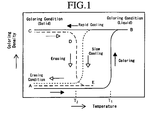
- FIG. 1 shows the relation between the developed color density and the temperature with respect to the thermoreversible recording medium.
- the temperature of the medium can be lowered to the room temperature while the medium maintains the color-developed condition, thereby the medium comes into the solid coloring condition (C).
- the medium comes into the solid coloring condition (C) or not depends on the cooling rate from the molten and coloring condition (B) as follows.
- the medium in the molten and coloring condition (B) is cooled slowly, the medium comes into the erasing condition (A) or into a condition in which a density of the developed color is relative lower than a density of the developed color in the solid coloring condition (C).
- the medium in the solid coloring condition (C) is heated again, a color of the medium is erased at the temperature T2 which is lower than the above-noted coloring temperature T1 (from D to E) and from here (E), when the medium is cooled, the medium returns into the initial erasing condition (A). Since actual color-developed and color-erased temperatures vary depending on an amount ratio between the coloring agent and color developer, the coloring and erasing temperatures can be properly selected depending on the application purpose of the medium. Further, the color density of the medium in the molten and coloring condition (B) is not always the same as the color density of the medium in the solid coloring condition (C).
- the color-developed condition (C) obtained through rapid cooling from the molten condition is a condition in which the coloring agent and color developer are mixed in such a state that they can react through a molecular contact and the color-developed condition may be often in a solid state. It is believed that the coloring condition (C) is a condition in which the coloring agent and color developer are agglomerated together, thereby maintaining a developed color and the formation of the agglomerated condition may stabilize the color-developed condition. On the other hand, in the erasing condition, the coloring agent and color developer are separated into two phases.
- the erasing condition is a condition in which molecules of at least one of the coloring agent and color developer are aggregated to form a domain or to be crystallized and by the aggregation or the crystallization, the coloring agent and color developer are stably separated.
- a condition in which the developed color is completely erased is formed through such a reaction that the coloring agent and color developer are separated into two phases and the color developer is crystallized .
- the agglomeration condition is changed at this temperature and the separation into two phases or the crystallization of the color developer is caused.
- the coloring recording may be formed by heating up to the temperature at which the coloring agent and color developer are molten and mixed by means of the thermal head and cooling rapidly.
- the methods for erasing the color include such two methods as a method in which the recording medium is cooled slowly from the molten coloring condition and a method in which the recording medium is heated to a little lower temperature than the color-developed temperature. The two methods are equivalent to each other in the meaning that the recording medium is temporally maintained at the temperature at which the coloring agent and color developer are separated into two phases or at least one of them is crystallized.
- the rapid cooling in the formation of the color-developed condition is performed so as not to maintain the recording medium at the temperature for either the phase-separation of the coloring agent and color developer or the crystallization.
- the terms of "rapid cooling” and “slow cooling” represent no more than a relative cooling rate with respect to a certain composition and the actual cooling rate is altered depending on the combination of the coloring agent and color developer.
- the electron-accepting compound (color developer) is not restricted so long as the compound can perform reversibly the color developing and erasing by the heating and may be properly selected depending on the application.
- Preferred examples of the electron-accepting compound include a compound having in the molecule at least one structure selected from the group consisting of (i) a structure which has a color-developing function to develop the color of an electron-donating coloring compound (coloring agent) (e.g., a phenolic hydroxyl group, a carboxylic acid group or a phosphoric acid group) and (ii) a structure which can control an intermolecular cohesive force (a group to which a long-chain hydrocarbon group is bonded).
- coloring agent e.g., a phenolic hydroxyl group, a carboxylic acid group or a phosphoric acid group
- a bonding part between a group and a long-chain hydrocarbon group may contain a divalent or more bonding group containing a hetero atom and a long-chain hydrocarbon group may contain at least one of the same bonding group as the above-noted bonding group and an aromatic group.
- a phenol compound represented by the following formula (1) is particularly preferred. wherein "n” represents an integer of 1 to 3; "X” represents a divalent organic group containing nitrogen atom or oxygen atom; R 1 and R 2 respectively represent an aliphatic hydrocarbon group which may be substituted with other substituents.
- R 1 represents an aliphatic hydrocarbon group having two or more carbon atoms, particularly preferably 5 or more carbon atoms, which may be further substituted with other substituents.
- R 2 represents a C 2 to C 24 , preferably C 8 to C 18 aliphatic hydrocarbon group, which may be further substituted with other substituents.
- the aliphatic hydrocarbon group may be linear or branched and may contain an unsaturated bond.
- substituent which is bonded to the above-noted aliphatic hydrocarbon group include a hydroxyl group, a halogen atom and an alkoxy group.
- R 1 include groups represented by the following formulae: wherein q, q', q", and q"' represent integers which are corresponding to the above-noted numbers of carbon atoms in R 1 and R 2 , respectively.
- these groups particularly preferred is -(CH 2 )q-.
- R 2 examples include groups represented by the following formulae: wherein q, q', q", and q"' represent integers which are corresponding to the above-noted numbers of carbon atoms in R 1 and R 2 , respectively. Among these groups, particularly preferred is -(CH 2 ) q -CH 3 .
- X represents a divalent organic group containing a nitrogen atom or an oxygen atom, which contains at least one group selected from the group consisting of the groups represented by the following formulae:
- Preferred examples of the above-noted divalent organic group include the groups represented by the following formulae.
- Preferred examples of the phenol compound represented by the formula (1) include the compounds represented by the following formulae (2) and (3). wherein in the formulae (2) and (3), "m" represents an integer of any one of 5 to 11 and "n” represents an integer of any one of 8 to 22.
- the electron-donating coloring compound (coloring agent) is not restricted and may be properly selected depending on the application.
- Preferred examples of the electron-donating coloring compound include leuco dyes.
- Preferred examples of the leuco dyes include fluoran compounds and azaphthalide compounds.
- fluoran compounds or azaphthalide compounds include 2-anilino-3-methyl-6-diethylaminofluoran, 2-anilino-3-methyl-6-(di-n-butylamino)fluoran, 2-anilino-3-methyl-6-(N-n-propyl-N-methylamino)fluoran, 2-anilino-3-methyl-6-(N-isopropyl-N-methylamino)fluoran, 2-anilino-3-methyl-6-(N-isobutyl-N-methylamino)fluoran, 2-anilino-3-methyl-6-(N-n-amyl-N-methylamino)fluoran, 2-anilino-3-methyl-6-(N-sec-butyl-N-methylamino)fluoran, 2-anilino-3-methyl-6-(N-n-amyl-N-eth
- Examples of the electron-donating coloring compound (coloring agent) include, besides the above-noted fluoran and azaphthalide compounds, conventional leuco dyes, such as 2-(p-acetylanilino)-6-(N-n-amyl-N-n-butylamino)fluoran, 2-benzylamino-6-(N-ethyl-p-toluidino)fluoran, 2-benzylamino-6-(N-methyl-2,4-dimethylanilino)fluoran, 2-benzylamino-6-(N-ethyl-2,4-dimethylanilino)fluoran, 2-dibenzylamino-6-(N-methyl-p-toluidino)fluoran, 2-dibenzylamino-6-(N-ethyl-p-toluidino)fluoran, 2-(di-p-methylbenzylamino)-6-(N-ethyl-p-toluidino)fluoran,
- the mixing ratio of the electron-donating coloring compound (coloring agent) to the electron-accepting compound (color developer) cannot be sweepingly determined, since the appropriate range of the ratio varies depending on the combination of a coloring agent used and a color developer used.
- the ratio of the color developer to 1 mol of the coloring agent is preferably in the range of from 0.1 to 20 mol, more preferably from 0.2 to 10 mol. Whether the ratio of the color developer is larger than this range or not, a disadvantage is likely to be caused wherein the density of the developed color is lowered. Further, the coloring agent and color developer can be used in a microcapsule encapsulated.
- an erasing accelerator such as a compound having in the molecule at least one group of amide group, urethane group and urea group
- an intermolecular reaction is induced between the erasing accelerator and the color developer during forming a state of erasing, so that the erasing rate can be markedly elevated.
- the erasing accelerator may be a compound having in the molecule at least one group of an amide group, an urethane group and an urea group.
- compounds represented by the following formulae (4) to (10) are particularly preferred.
- R 4 - NHCO - R 5 Formula(4) R 4 -NHCO-R 6 -CONH-R 5 (Formula(5) R 4 -CONH-R 6 -NHCO-R 5 Formula(6) R 4 -NHCOO-R 5 Formula(7) R 4 -NHCOO-R 6 -OCONH-R 5 Formula(8) R 4 -OCONH-R 6 -NHCOO-R 5 Formula(9) wherein R 4 , R 5 , and R 7 in the formulae (4) to (10) represent a C 7 to C 22 linear alkyl group, a C 7 to C 22 branched alkyl group and a C 7 to C 22 unsaturated alkyl group, respectively.
- R 6 represents a C 1 to C 10 divalent functional group.
- R 8 represents a C 4 to C 10 trivalent functional group.
- R 4 , R 5 , and R 7 include a heptyl group, an octyl group, a nonyl group, a decyl group, an undecyl group, a dodecyl group, a stearyl group, a behenyl group, and an oleyl group.
- R 6 examples include a methylene group, an ethylene group, a propylene group, a buthylene group, a heptamethylene group, a hexamethylene group, an octamethylene group, a -C 3 H 6 OC 3 H 6 - group, a -C 2 H 4 OC 2 H 4 - group and a -C 2 H 4 OC 2 H 4 OC 2 H 4 - group.
- R 8 include the compounds represented by the following formulae:
- Preferred specific examples of the compounds represented by the formulae (4) to (10) include the compounds represented by the following formulae (1) to (81). (1) C 11 H 23 CONHC 12 H 25 (2) C 15 H 31 CONHC 16 H 33 (3) C 17 H 35 CONHC 18 H 37 (4) C 17 H 35 CONHC 18 H 35 (5) C 21 H 41 CONHC 18 H 37 (6) C 15 H 31 CONHC 18 H 37 (7) C 17 H 35 CONHCH 2 NHCOC 17 H 35 (8) C 11 H 23 CONHCH 2 NHCOC 11 H 23 (9) C 7 H 15 CONHC 2 H 4 NHCOC 17 H 35 (10) C 9 H 19 CONHC 2 H 4 NHCOC 9 H 19 (11) C 11 H 23 CONHC 2 H 4 NHCOC 11 H 23 (12) C 17 H 35 CONHC 2 H 4 NHCOC 17 H 35 (13) (CH 3 ) 2 CHC 14 H 35 CONHC 2 H 4 NHCOC 14 H 35 (CH 3 ) 2 (14) C 21 H 43 CONHC 2 H 4 NHCOC 21 H 43 (15) C 17 H 35 CONHC 6 H 12 NHCOC
- the amount of the erasing accelerator is preferably 0.1 to 300 parts by mass, more preferably 3 to 100 parts by mass, relative to 100 parts by mass of the color developer.
- the amount is less than 0.1 parts by mass, the effect of the added erasing accelerator may be impaired, on the other hand, when the amount is more than 300 parts by mass, the density of the developed color may be lowered.
- the thermosensitive layer may comprise, besides the above-noted components, a binder resin, and optionally various additives for improving the coating property and the color diveloping and erasing property of the thermosensitive layer.
- additives include crosslinker, crosslinking accelerator, filler, lubricant, surfactant, conducting agent, loading material, antioxidant, solar proof material, color stabilizer, plasticizer.
- the binder resin is not restricted and may be properly selected depending on the application.
- the binder resin include polyvinyl chloride resins, polyvinyl acetate resins, vinylchloride-vinylacetate copolymers, ethylcellulose, polystyrene resins, styrene copolymers, phenoxy resins, polyester resins, aromatic polyester resins, polyurethane resins, polycarbonate resins, polyester acrylate resins, polyester methacrylate, acryl copolymers, maleic acid copolymers, polyvinylalcohol resins, modified polyvinylalcohol resins, hydroxylethylcellulose, carboxymethylcellulose and starch.
- binder resins serve to maintain a condition in which each material of the composition in the thermosensitive layer is uniformly dispersed in a coating liquid for the thermosensitive layer, unless each material is polarizedly dispersed by the heating for repeating the printing and erasing.
- the binder resin used is preferably a resin having high heat-resistance.
- a curable resin which comprises a crosslinker and can be crosslinked by means of heat, ultra-violet or electron beam hereinafter, sometimes referred to as "crosslinking resin"
- crosslinking resin By incorporating a curable resin in the thermosensitive layer, the heat-resistance and the coating strength of the thermosensitive layer and the repetition durability of the recording medium can be improved.
- the curable resin is not restricted and may be properly selected depending on the application.
- the curable resin include resins having a group reactive with a crosslinker and resins produced by copolymerizing a monomer having a group reactive with a crosslinker with another monomer, such as acrylpolyol resins, polyesterpolyol resins, polyurethanepolyol resins, phenoxy resins, polyvinylbutyral resins, cellulose acetate propionate and cellulose acetate butylate.
- acrylpolyol resins, polyesterpolyol resins and polyurethanepolyol resins are preferred.
- the hydroxyl value of the thermosetting resin is preferably 70 KOHmg/g or more, more preferably 90 KOHmg/g or more.
- the hydroxyl value is 70 KOHmg/g or more, the durability, the surface hardness of a coating formed from the resin and cracking resistance can be improved.
- the hydroxyl value may influence the crosslinking density and consequently influence chemical resistance and properties of the coating.
- the acrylpolyol resin may be synthesized by using a (meth)acrylic ester monomer and at least one unsaturated monomer selected from the group consisting of a unsaturated monomer having carboxyl group, a unsaturated monomer having hydroxyl group and a unsaturated monomer having ethylene group according to a conventional polymerization method, such as a solution polymerization, a suspension polymerization and emulsion polymerization.
- a conventional polymerization method such as a solution polymerization, a suspension polymerization and emulsion polymerization.
- Examples of the unsaturated monomer having hydroxyl group include hydroxyethylacrylate (HEA), hydroxypropylacrylate (HPA), 2-hydroxyethylmethacrylate (HEMA), 2-hydroxypropylmethacrylate (HPMA), 2-hydroxybutylmonoacrylate (2-HBA), and 1,4-hydroxybutylmonoacrylate (1-HBA). Since a coating formed from a resin produced using a monomer having a primary hydroxyl group exhibits excellent cracking resistance and excellent durability, 2-hydroxyethylmethacrylate is preferably used.
- crosslinker examples include conventional isocyanate compounds, amines, phenols, epoxy compounds. Among these compounds, isocyanate compounds are particularly preferred.
- the isocyanate compound is not restricted and may be properly selected depending on the application.
- the isocyanate compound include modified forms of isocyanate monomer, such as urethane modified form, allophanate modified form, isocyanurate modified form, buret modified form, carbodiimide modified form and blockedisocyanate.
- HMDI dicyclohexylmethanediisocyanate
- IPDI isophoronediisocyanate
- LLI lysinediisocyanate
- IPC isopropylidenebis(4-cyclohexylisocyanate)
- CHDI cyclohexyldiisocyanate
- TODI tolidinediisocyanate
- crosslinking accelerator a catalyst which is used generally in similar reactions to the crosslinking may be employed.
- the crosslinking accelerator include tertiary amines such as 1,4-diaza-bicyclo(2,2,2)octane, and metal compounds such as organotin compounds. It is not necessary that all amount used of a crosslinker is reacted. That is, an unreacted crosslinker may be remained. Such crosslinking reaction may progress with time; therefore, the presence of unreacted crosslinker indicates neither that a crosslinking reaction has not progressed at all, nor that a crosslinked resin is not present.
- a method for judging whether a polymer is crosslinked or not is a method in which the coating is immersed in a solvent having a high solubility of polymers.
- a polymer in the coating is crosslinked or not.
- gel fraction is employed for judging whether a polymer is crosslinked or not.
- gel fraction means the percentage of the gel formed in a solvent, wherein resin solutes lose the independent mobility in the solvent due to the interaction and are agglomerated into a solidified gel.
- the gel fraction of the resin is preferably 30 %, more preferably 50 %, still more preferably 70 %, most preferably 80 %. When the gel fraction is low, the repetition durability of the resin is lowered.
- a curable resin which is cured by means of heat, ultraviolet (UV) irradiation or electron beam (EB) irradiation may be incorporated into the resin or the resin itself may be crosslinked.
- the gel fraction can be determined as follows. A piece of a coating is peeled from the support to weigh the initial mass. Then the coating is nipped between wire nets of 400 mesh and immersed into a solvent in which the resin which is not crosslinked is soluble, for 24 hours. The coating is dried under vacuum, then the mass of the coating after the drying is measured.
- the gel fraction may be calculated by the following equation.
- Gel Fraction ( % ) mass after drying g / initial mass ( g ) ⁇ 100
- the mass of the organic substances having a lower molecular weight which are not the resin components of the thermosensitive layer, should be eliminated.
- the gel fraction may be obtained by an observation of the resin cross-section by means of transmittance electron microscope (TEM) or scanning electron microscope (SEM) and by measuring the area ratio of the resin and organic substances having a lower molecular weight; and from the area ratio and the respective specific gravity, the mass of the organic substances having a lower molecular weight can be obtained.
- TEM transmittance electron microscope
- SEM scanning electron microscope
- the gel fraction when the thermosensitive layer is disposed on the support and another layer, such as a protective layer is disposed on the thermosensitive layer, or when another layer is disposed between the support and the thermosensitive layer, the gel fraction can be similarly determined as follows.
- the layer thicknesses of the thermosensitive layer and another layer are respectively measured through the observation using TEM or SEM and a layer having a thickness corresponding to the thickness of another layer is shaved off, thereby the thermosensitive layer is exposed.
- the exposed thermosensitive layer is peeled off and the gel fraction thereof is measured by the above-noted method.
- thermosensitive layer when a protective layer comprising an UV curable resin is disposed on the thermosensitive layer, for preventing the sample for determining the gel fraction of the thermosensitive layer from contamination by intrusion of a peeled part of the protective layer into the sample as little as possible, it is necessary that before preparing the sample, a layer corresponding to the thickness of the protective layer and a small part of the thermosensitive layer should be peeled off and discarded.
- inorganic fillers include calcium carbonate, magnesium carbonate, anhydrous silicic acid, alumina, iron oxide, calcium oxide, magnesium oxide, chromium oxide, manganese oxide, silica, talc, and mica.
- organic fillers examples include silicone resins, cellulose resins, epoxy resins, nylon resins, phenol resins, polyurethane resins, urea resins, melamine resins, polyester resins, polycarbonate resins, polystyrene resins, polystyreneisoprene, polystyrenevinylbenzene, polyvinylidenechloride, acrylurethane resins, ethyleneacryl resins, polyethylene resins, benzoguanazineformaldehyde resins, melamine formaldehyde resins, polymethylmethacrylate resins, and polyvinylchloride.
- fillers may be used individually or in combination. When plural fillers are used, with respect to the combination of an inorganic filler and an organic filler, there is not particular limitation.
- forms of a filler include sphere, granular, platelet and needle.
- the amount of a filler is usually 5 to 50 % by volume.
- the lubricant is not ristricted and may be properly selected from conventional lubricants depending on the application.
- the lubricant include synthetic waxes, such as ester wax, paraffin wax and polyethylene wax; vegetable waxes, such as hardened castor oil; animal waxes, such as hardened beef tallow; higher alcohols, such as stearyl alcohol and benyl alcohol; higher aliphatic acids, such as margaric acid, lauric acid, myristic acid, palmic acid, stearic acid and behenolic acid; higher aliphatic acid esters, such as aliphatic acid ester of sorbitan; and amides, such as stearic acid amide, oleic acid amide, lauric acid amide, ethylenebisstearic acid amide, methylenebisstearic acid amide and methylolstearic acid amide
- the amount of lubricants in the thermosensitive layer is preferably 0.1 to 95 % by volume, more preferably 1 to 75 % by volume.
- the surfactant is not restricted and may be properly selected depending on the application.
- examples of the surfactant include an anionic surfactant, cationic surfactant, nonionic surfactant and amphoteric surfactant.
- thermosensitive layer The method for disposing the above-noted thermosensitive layer is not restricted and may be properly selected depending on the application.
- the method include (1) a method in which the coating liquid for the thermosensitive layer prepared by dissolving or dispersing the binder resin, the electro-donating coloring compound and the electron-accepting compound in a solvent, is coated on the support and either during or after evaporating off the solvent to produce the coated support in the form of a sheet, the thermosensitive layer is crosslinked; (2) a method in which the coating liquid for the thermosensitive layer prepared by dispersing the electro-donating coloring compound and the electron-accepting compound in a solvent in which only the binder resin is dissolved, is coated on the support and either during or after evaporating off the solvent to produce the coated support in the form of a sheet, the thermosensitive layer is crosslinked; and (3) a method in which without using a solvent, the binder resin, the electron-donating coloring compound and the electron-accepting compound are molten by the heating and mixed to form a mixture and after the molten
- thermoreversible recording medium in the form of a sheet can be shaped without using the support.
- the solvent used in the methods (1) or (2) is not determined sweepingly, since the solvent is determined depending on the type of the electron-donating coloring compound and the electron-accepting compound; however, examples of the solvent include tetrahydrofuran, methylethylketone, methylisobutylketone, chloroform, carbontetrachloride, ethanol, toluene and benzene.
- the electron-accepting compound is dispersed in the form of particles in the thermosensitive layer.
- the coating liquid for the thermosensitive layer may contain various pigments, anti-forming agents, dyes, dispersants, lubricants, preservatives, crosslinkers and plasticizers.
- the coating process is not restricted and may be properly selected depending on the application.
- the process is performed by a method in which, the support in a continuous sheet supplied from a roll or in a cut sheet is conveyed and on the support, the coating liquid is coated by a conventional coating process, such as a blade process, wire-bar process, spray process, air-knife process, bead process, curtain process, gravure process, kiss process, reverse roll process, dip process and die coating process.
- a conventional coating process such as a blade process, wire-bar process, spray process, air-knife process, bead process, curtain process, gravure process, kiss process, reverse roll process, dip process and die coating process.
- the condition for drying the coated liquid for the thermosensitive layer is not restricted and may be properly selected depending on the application.
- the drying is performed approximately at from room temperature to 140 °C for from 10 minutes to 1 hour.
- the curing of the resin in the thermosensitive layer can be performed by means of heating, UV irradiation, or electron beam irradiation.
- the UV irradiation may be performed by means of a conventional UV irradiation apparatus.
- Examples of the UV irradiation apparatus include an apparatus equipped with a UV source, light kit, power supply, cooling device and conveying instrument.
- UV source examples include a mercury lump, metal halide lump, gallium lump, mercury xenon lump and flash lump.
- the wavelength of the UV source may be selected depending on the wavelength of an absorbed UV by the photopolymerization initiator or the photopolymerization accelerator comprised in the composition of the recording medium.
- the condition of UV irradiation is not restricted and may be properly selected depending on the application.
- the lump power and the conveying rate may be determined depending on the exposed energy necessary for crosslinking the resin.
- the electron beam irradiation may be performed by means of conventional electron beam irradiation apparatuses.
- Such electron beam irradiation apparatuses may be summarily divided into scanning bean type and area beam type, and the type may be selected considering the irradiation area, irradiation dose and the like.
- the condition of irradiation may be calculated from the following equation (2), depending on the dose required for crosslinking the resin and considering the electron current, irradiation width, carrying rate and the like.
- D ⁇ E / ⁇ R ⁇ ⁇ ⁇ ⁇ I / W ⁇ V
- D represents the required dose (Mrad);
- ⁇ E / ⁇ R represents averaged energy loss;
- ⁇ represents efficiency;
- I represents electron current (mA);
- W represents irradiation width; and
- V represents carrying rate.
- the rating of the instrument is expressed by "Mrad-m / min", the rating of the electron current is selected from about 20 to 500 mA.
- thermosensitive layer is not restricted and may be properly selected depending on the application; for example, preferably 1 to 20 ⁇ m, more preferably 3 to 15 ⁇ m.
- the image contrast may come to low due to a lower coloring density
- the intended coloring density may not be obtained since the temperature distribution comes to broad in the film thereby non-coloring parts appear due to the lower temperature.
- thermoreversible recording medium of the present invention for protecting the thermosensitive layer from a solvent or a resin component in a coating liquid for disposing the protective layer, an intermediate layer may be disposed between the protective layer and the thermosensitive layer (see JP-A No. 1-133781).
- the intermediate layer comprises an ultraviolet absorber, a curable resin and optionally other components.
- the curable resin examples include an ultraviolet curing resin and a thermosetting resin.
- Specific examples of the curable resin include, besides above exemplified materials for a binder resin in the back layer, a polyethylene, polypropylene, polystyrene, polyvinyl alcohol, polyvinyl butyral, polyurethane, saturated polyester, unsaturated polyester, epoxy resin, phenol resin, polycarbonate and polyamide.
- the intermediate layer may preferably comprise an UV ray absorber.
- an UV ray absorber both an inorganic and an organic compound may be used.
- the organic UV ray absorber include benzotriazoles, benzophenones, salicylates, cyanoacrylates and cinnamic acids. Among these compounds, benzotriazoles are preferred. Further, among benzotriazoles, benzotriazoles in which a hydroxyl group is protected by an adjacent bulky functional group are particularly preferred.
- a UV ray absorber may be also a compound in which a skeleton having a function of absorbing UV ray is added to a copolymer, such as an acryl resin or a styrene resin.
- the amount of the UV ray absorber is preferably 0.5 to 10 % by mass, based on the total mass of the resin composition in the intermediate layer.
- a metal compound having an average particle diameter of 100 nm or less is preferred.
- the metal compound include metal oxides or complex metal oxides, such as zinc oxide, indium oxide, alumina, silica, zirconium oxide, tin oxide, cerium oxide, iron oxide, antimony oxide, barium oxide, bismuth oxide, nickel oxide, magnesium oxide, chromium oxide, manganese oxide, tantalum oxide, niobium oxide, thorium oxide, hafnium oxide, molybdenum oxide, iron ferrite, nickel ferrite, cobalt ferrite, barium titanate and potassium titanate; metal sulfides or metal sulfates, such as zinc sulfide and barium sulfate; metal carbides, such as titanium carbide, silicon carbide, molybdenum carbide, tungsten carbide and tantalum carbide; and metal nitride, such as aluminum nitride, silicone nitride
- ultra fine particle of a metal oxide such as silica, almina, zinc oxide, titanium oxide and cerium oxide.
- the super fine particles of metal oxides may be used of which the surface is treated with silicone, wax, organic silane or silica.
- the amount of the UV ray absorbing inorganic compounds is preferably 1 to 95 % by volume.
- These organic or inorganic UV ray absorbers may be incorporated also in the thermosensitive layer.
- the film thickness of the intermediate layer is preferably from 0.1 to 20 ⁇ m, more preferably from 0.5 to 5 ⁇ m.
- a conventional method used in disposing the back layer, the thermosensitive layer and the protective layer may be used.
- a heat-insulating undercoat layer may be disposed between the support and the thermosensitive layer. Further, the undercoat layer can be disposed by coating a coating liquid comprising a binder resin containing ultra fine hollow particles. An undercoat layer for the purpose of improving the adhesion between the support and the thermosensitive layer and preventing the penetration of a thermosensitive material into the support may be disposed.
- the same resin as a resin used for the thermosensitive layer or the protective layer may be used.
- the thermosensitive layer and the undercoat layer may comprise, not only at least one of an inorganic filler, such as calcium carbonate, magnesium carbonate, titanium oxide, silicon oxide, aluminum hydroxide, kaolin and talc, and an organic filler, but also lubricants, surfactants and dispersants.
- a coloring layer is disposed between the support and the thermosensitive layer.
- the coloring layer can be disposed either by coating a solution or dispersion containing a coloring agent and a binder resin on an objective surface and drying the disposed coloring layer or only by applying a coloring sheet on an objective surface.
- the recording medium may comprise also a color printing layer.
- a coloring agent for the color printing layer include various dyes and pigments which are contained in a color ink used for a conventional color printings and examples of the binder resin for the color printing layer include various thermoplastic resins, thermosetting resins, UV-curing resins and electron beam-curing resins.
- the thickness of the color printing layer is varied properly depending on a printing color density and may be selected according to a desired printing color density.
- the recording medium may comprise also an air layer as a buffer part between the support and the thermosensitive layer.
- the refraction coefficient of the polymer used in the thermosensitive layer is from 1.4 to 1.6 which differs largely from 1.0 which is the refraction coefficient of the air. Therefore, when the recording medium comprises the air layer, the light is reflected at the interface between the thermosensitive layer and the air layer and when the thermosensitive layer is in a condition of the opaque color, the opaque color can be amplified, so that the visuality can be improved. Therefore, the air layer as the buffer part may be preferably used as a display part.
- the air layer may function also as a heat-insulating layer, thereby improving the thermosensitivity of the recording medium and further as a cushion layer, thereby scattering the pressure of the thermal head, so that a distortion or a surface peeling of the thermosensitive layer by the mechanical force can be prevented and accordingly, the repetition durability of the recording medium can be improved.
- the thermoreversible recording medium of the present invention may also comprise a head matching layer.
- materials for the head matching layer include a thermoresistant resin and an inorganic pigment.
- the thermoresistant resin the same thermoresistant resin as a thermoresistant resin used for the protective layer may be preferably used.
- the inorganic pigment include calcium carbonate, kaolin, silica, aluminum hydroxide, alumina, aluminum silicate, magnesium hydroxide, magnesium carbonate, magnesium oxide, titanium oxide, zinc oxide, barium sulfate and talc. These inorganic pigments may be used individually or in combination.
- the particle diameter of the inorganic pigment is preferably from 0.01 to 10.0 ⁇ m, more preferably from 0.05 to 8.0 ⁇ m.
- the amount of the inorganic pigment is preferably from 0.001 to 2 parts by mass, more preferably from 0.005 to 1 part by mass, relative to 1 part by mass of the thermoresistant resin.
- a light-heat conversion layer which can convert a light energy into a heat energy by absorbing a laser light may be also disposed.
- the recording medium may comprise also at least one printing layer.
- the color printing layer or the head matching layer is cured by means of heat, UV or electro beam, a crosslinker, a photopolymerization initiator or a photopolymerization accelerater used for crosslinking a resin in the back layer or the thermosensitive layer is preferably incorporated.
- thermoreversible recording medium is not restricted and may be shaped into various forms depending on the application, such as a card, a sheet or a roll.
- Examples of the applications of the recording medium include a prepaid card, a point card and a credit card.
- the recording medium shaped into a sheet having a size of a general document, such as A4 size may be applied broadly into temporary output applications, such as normal document, instructing letter for process control, circulation document, and conference data, needless to say trial printings, owing to the wider printable area than the card size when an printing-erasing apparatus is introduced.
- the recording medium shaped into the form of a roll may be applied for display board, notice plate and electronic white board by being integrated into an instrument with a printing-erasing part.
- display instruments can be preferably used in a clean room, since dusts and contaminants are not emitted from the display instrument.
- the recording medium may also comprise an irreversible thermosensitive layer.
- the developed color of the irreversible thermosensitive layer may be either the same as or different from the developed color of the reversible thermosensitive layer.
- a printing such as offset printing and gravure printing or coloring layer with any patterns may be provided partially or entirely by means of an inkjet printer, heat transfer printer, or sublimation type printer.
- an OP varnish layer based on curable resin may be provided on the entire or part of the coloring layer. Examples of the above-noted optional pattern include letter, design, figure, photography and infrared-detectable information.
- any one of the respective layers constituting the recording medium may be colored simply by adding dyes or pigments to the layers.
- the recording medium may be provided with a hologram for the security.
- design such as a personal image, company mark or symbol mark may be provided by applying concaves and convexes of relief or interior (dug or carved patterns).
- thermorversible recording medium The forming and erasing of images on the thermorversible recording medium can be performed by means of conventional image processing apparatus, preferably by means of the image processing apparatus as explained below.
- Preferred examples of the image processing apparatus include apparatus equipped with an image forming unit for forming images on the recording media and an image erasing unit for erasing images from the recording media. Among them, from the viewpoint of a short processing period, apparatus equipped with a combined unit for forming and erasing image is more preferred.
- an image processing apparatus equipped with a thermal head in which the images can be processed by changing the energy applied on the thermal head
- the thermalreversible recording media according to the present invention comprises an information-memorizing part and a reversible displaying part and the reversible display part comprises the thermoreversible recording medium according to the present invention.
- thermoreversible recording medium the reversibly displayable thermosensitive layer and the information-memorizing part are provided in an identical card (integrated), and a part of the memorized information of the information-memorizing part is displayed on the thermosensitive layer, thereby the owner of the card may be convenient in that the information can be confirmed by only viewing the card without a particular device. Further, in the case that the amount of the information-memorizing part is overwritten, the recording medium may be repeatedly used by overwriting the display of the thermosensitive recording part.
- the member comprising the information-memorizing part and the reversible displaying part may be summarily divided into the following two types.
- the information-memorizing part and the reversible displaying part are so disposed that they can exhibit their own functions and so long as they can exhibit their own functions
- the information-memorizing part may be disposed on a surface of the support which is opposite to another surface of the support on which the thermosensitive layer is disposed, between the support and the thermosensitive layer, or on a part of the thermosensitive layer.
- the information-memorizing part is not restricted and may be formed of a magnetic thermosensitive layer, magnetic stripe, IC memory, optical memory, hologram, RF-ID tag card and the like.
- a magnetic thermosensitive layer magnetic stripe
- IC memory magnetic stripe
- optical memory hologram
- RF-ID tag card preferably employed in the sheet medium of which the size is over the card size.
- an IC memory, RF-ID tag are preferably employed.
- the RF-ID tag is composed of an IC chip and an antenna connected to the IC chip.
- the magnetic thermosensitive layer may be disposed by coating on the support using coating materials comprising metal compounds used conventionally, such as iron oxide and barium ferrite and resins, such as vinylchloride resins, urethane resins and nylon resins, or by a method, such as vapor deposition or spattering without using resins.
- the magnetic thermosensitive layer may be disposed on a surface of the support which is opposite to another surface of the support on which the thermosensitive layer is disposed, between the support and the thermosensitive layer, or on a part of the thermosensitive layer.
- the thermoreversible material for displaying may be employed for the memorizing part in a form of barcode, two dimensional code and the like. Among them, the magnetic recording and IC are further preferred.
- the hologram As for the hologram, a rewritable type is preferred.
- the hologram include the rewritable hologram in which coherent light is written on a liquid crystal film of azobenzene polymer.
- the member comprising the information recording part include a card, a disc, a disc cartridge and a tape cassette.
- Specifical examples of the member include a thicker card such as IC card and an optical card; a disc cartridge containing an information-rewritable disc, such as optical magnetic disc (MD) and DVD-RAM; a disc in which disc cartridge is not used, e.g. CD-RW; an overwrite type disc such as CD-R; an optical information recording medium with phase-changing recording material (CD-RW); and a videotape cassette.
- the member comprising the information-memorizing part and the reversible displaying part may exhibit remarkably increased availability. That is, in case of card for example, the owner of the card can confirm the information only by viewing the card without a particular device through displaying on the thermosensitive layer a part of the information memorized in the information recording part.
- the information-memorizing part is not restricted so long as a necessary information can be recorded and may be properly selected depending on the application. Examples thereof include a magnetic recording, a contact type IC, a non-contact type IC and optical memory.
- the magnetic thermosensitive layer may be disposed by coating on a support a coating material comprising conventional iron oxide, barium ferrite etc. and vinylchloride resins, urethane resins, nylon resins, otherwise by vapor deposition, spattering etc. without using resins. Further, the thermoreversible material for displaying may be employed for the memorizing part in a form of barcode, two dimensional code and the like.
- the recording medium may be appropriately employed for the thermoreversible recording medium, thermoreversible recording member, image processing apparatus, and image processing method.
- surface of the thermoreversible recording medium means the surface of the thermosensitive side such as the surface of printing layer or OP layer, not only of the protective layer but all of or part of the surface which contact with the thermal head during the printing and erasing.
- the thermoreversible recording member comprises a reversibly displayable thermosensitive layer and an information recording part, and an RF-ID tag is exemplified as a preferable information recording part.
- FIG. 2 schematically shows RF-ID tag 85.
- the RF-ID tag 85 is composed of IC chip 81, and antenna 82 connected to the IC chip.
- the IC chip 81 is divided into four parts of memorizing part, power supply controlling part, transmitting part and receiving part; the respective part are imposed individual roll, and communications are performed.
- the communications are achieved through exchanging data using electric waves by means of the antennas of RF-ID tag and the reader-writer. Specifically, the antenna of RF-ID receives electric waves to cause an electromotive force through an induction due to resonance effect.
- the IC chip in the RF-ID tag is activated, the information in the chip is turned into signals, followed by the dispatch of the signals from the RF-ID tag.
- the information is received by the antenna of the reader-writer to recognize it by the data processing apparatus, and then data processing is achieved at the soft side.
- the RF-ID tag is formed into label-like or card-like shape. As shown FIG. 3, RF-ID tag 85 may be laminated to the thermoreversible recording medium 90. RF-ID tag 85 may be laminated on the surface of thermosensitive layer or back layer, preferably on the surface of back layer. For the purpose of laminating the RF-ID tag and the recording medium, conventional adhesive agents and tacky agents may be used.
- FIGs. 4A and 4B exemplify the thermoreversible recording media applied into commercial rewritable sheet 90 (thermoreversible recording medium).
- a rewritable displaying part 86 is provided on the thermosensitive layer side where a barcode printing part 87 may be provided.
- the RF-ID tag On the behind side (back layer), the RF-ID tag may not be laminated (88) as shown in FIG. 4B, or the RF-ID tag may be laminated as shown in FIG. 3.
- the application of RF-ID tag is preferable in light of higher availability.
- FIG. 5 exemplifies the way in which the commercial rewritable sheet combined with the thermoreversible recording medium (rewritable sheet) and RF-ID tag is used.
- information such information as an article name and amount is recorded on the rewritable sheet or RF-ID tag with respect to the delivered raw materials, and the raw material are inspected with the information of the rewritable sheet or RF-ID tag contained in a circulating box for example.
- a working instruction is granted on the delivered raw material, the rewritable sheet and RF-ID tag with the recorded information turn to the working instruction letter, and progress to the working step.
- the rewritable sheet and RF-ID tag recorded with the order information is attached to the worked product as the order instruction letter.
- the rewritable sheet is recovered after the shipment, the shipment information is subjected to reading, then the rewritable sheet is used as a delivery letter again.
- thermoreversible recording label comprises at least one of an adhesive layer and tacky layer disposed on a surface of the support which is opposite to another surface of the support on which an image forming layer (for example, the thermosensitive layer) of the thermoreversible recording medium is disposed.
- the recording label comprises also other layers selected properly depending on the necessity. Further, in the case that the support of the recording medium exhibits thermal fusion bond property, it is not necessary that the adhesive layer or tacky layer is disposed on the surface of the support.
- the form, configuration and size of the adhesive layer or tacky layer are not restricted and may be properly selected depending on the application.
- the form may be sheet-like or film-like; the configuration may be of single layer or laminated layers; and the size may be larger or smaller than the thermosensitive layer.
- the material of the adhesive layer or tacky layer is not restricted and may be properly selected depending on the application.
- the material include urea resins, melamine resins, phenolic resins, epoxy resins, polyvinyl acetate resins, vinyl acetate-acrylic copolymers, ethylene-vinyl acetate copolymers, acrylic resins, polyvinyl ether resins, vinyl chloride-vinyl acetate copolymers, polystyrene resins, polyester resins, polyurethane resins, polyamide resins, chlorinated polyolefin resins, polyvinyl butyral resins, acrylic ester copolymers, methacrylic ester copolymers, natural rubber, cyanoacrylate resins, silicone resins. These may be used individually or in combination. Further the material may be of hot-melt type, and may be used either with a disposable release paper or without a disposable release paper.
- thermoreversible recording label is generally used in a configuration laminated to a substrate sheet such as a card, in which the thermoreversible recording label may be laminated on the entire or part of the substrate sheet, or on one side or both sides.
- the form, configuration and size of the substrate sheet are not restricted and may be properly selected depending on the application.
- the form may be platelet and the like; the configuration may be of single layer or laminated layers; and the size may be properly selected depending on the size of the thermoreversible recording medium.
- the substrate sheet include a sheet and a laminated form of the sheet which are produced from a chlorine-containing polymer, a polyester resin, a biodegradable plastic.
- the chlorine-containing polymer is not restricted and may be properly selected depending on the application.
- the polymer include polyvinyl chloride, vinyl chloride-vinyl acetate copolymers, vinylchloride-vinylacetate-vinylalcohol copolymers, vinylchloride-vinylacetate-maleicacid copolymers, vinylchloride-acrylate copolymers, polyvinylidenechloride, vinylidenechloride-vinylchloride copolymers, and vinylidenechloride-acrylonitrile copolymers.
- polyester resins examples include polyethylene terephthalate (PET), polybutylene terephthalate (PBT), alternatively condensed esters of acid ingredients such as terephthalic acid, isophthalic acid, and alcohol ingredients such as ethylene glycol, cyclohexanedimethanol (e.g. PETG, trade name by Eastman Chemical Co.).
- PET polyethylene terephthalate
- PBT polybutylene terephthalate
- alternatively condensed esters of acid ingredients such as terephthalic acid, isophthalic acid
- alcohol ingredients such as ethylene glycol, cyclohexanedimethanol (e.g. PETG, trade name by Eastman Chemical Co.).
- biodegradable plastic examples include natural polymer resins comprising polylactic acid, starch, denaturated polyvinyl alcohol and the like, and microbiological product resins including ⁇ -butyric acid and ⁇ -valeric acid.
- the substrate may be synthetic resin sheet or paper formed of polyacetate resins, polystyrene (PS) resins, epoxy resins, polyvinylchloride (PVC) resins, polycarbonate (PC) resins, polyamide resins, acryl resins, silicone resins and the like. These materials may be properly combined or laminated.
- PS polystyrene
- PVC polyvinylchloride
- PC polycarbonate
- acryl resins polyamide resins
- silicone resins silicone resins and the like.
- Examples of the laminated form include a form comprising a core sheet formed of laminated two sheets of white polyvinyl chloride resin having a thickness of 250 ⁇ m and two laminated oversheets of transparent polyvinyl chloride resin having a thickness of 100 ⁇ m, wherein an oversheet is laminated on the upper side of the core sheet and another oversheet is laminated on a lower side of the core sheet; and a form comprising a core sheet formed of laminated two sheets of white PETG having a thickness of 250 ⁇ m and two laminated oversheets of transparent PETG having a thickness of 100 ⁇ m, wherein an oversheet is laminated on the upper side of the core sheet and another oversheet is laminated on a lower side of the core sheet.
- thermoreversible recording label 3 and substrate sheet 4 are superimposed oppositely, and disposed and pressed between two sheets of mirror plate 2, along with being heated through hot plate 1.
- the similar way may be applied toward the substrate sheet 4, which is composed of the superimposed core sheet 6 and over sheet 7.
- the adhesion with press and heat may be performed through a conventional way, normally at the pressure of 5 to 70 kgf/cm 2 , preferably 10 to 50 kgf/cm 2 , and at the temperature of 80 to 170 °C, preferably 90 to 150 °C, by means of a hot-pressing apparatus equipped with heating plate 1 (for example).
- the heating temperature at the hot pressing is preferably 130 to 150 °C. Further, in the case that the laminate of transparent PETG/white PETG/white PETG/transparent PETG is employed, the heating temperature at the hot pressing is preferably 100 to 130 °C.
- the substrate sheet and the thermoreversible recording label are adhered with heating previously, then laminated with heating.
- the adhesion with heating may be achieved by pressing a rubber roll against them followed by laminating with heating.
- the optimal condition of the adhesion with heating is not restricted and may be properly selected depending on the substrate sheet in use, normally performed by keeping at 90 to 130 ⁇ C for 1 hour or less, preferably 1 to 50 minutes.
- thermoreversible recording label comprises a protective layer of which surface is roughened by filler and the like, and the recording label is adhered with heating and pressing on a label-like substrate
- the filler at the surface of the protective layer is pressed into the protective layer or underlying layer through the heating and pressing, thereby the surface gross increases and the repetition durability decreases due to the lowering of the filler effect, and also that when printing and erasing are repeated in the condition of the increased surface gloss, the gloss at the printed-erased parts is decrease, as a result that the gloss difference from the non-printed-erased parts comes to be recognized as a non-uniformity.
- the presence of the protective layer in the thermoreversible recording medium may eliminate such matters.
- the surface roughness 0.15 ⁇ m or less of the recording medium is more preferred since higher gloss may be obtained.
- the recording medium may be affixed on an entire or part of a thicker substrate such as polyvinylchloride card with magnetic stripe to which the recording medium is usually difficult to be affixed, thereby a part of the information memorized in magnetic may be displayed.
- thermoreversible recording label may be an alternative to a thicker card such as IC card and optical card, flexible disc, disc cartridge containing rewritable disc such as optical magnetic recording disc (MD) and DVD-RAM, disc without disc cartridge such as CD-RW, write-once disc such as CD-R, optical information recording medium (CD-RW) based on phase-change recording material, and display label on videotape cassette.
- a thicker card such as IC card and optical card
- flexible disc disc cartridge containing rewritable disc such as optical magnetic recording disc (MD) and DVD-RAM
- disc without disc cartridge such as CD-RW
- write-once disc such as CD-R
- CD-RW optical information recording medium
- FIG. 8 exemplifies the recording medium 10 affixed to MD disc cartridge 70.
- the recording medium 10 affixed to MD disc cartridge 70.
- the displayed amount is automatically altered depending the alternation of the memorized amount in the MD.
- the recording label may be directly affixed to the disc.
- FIG. 9 exemplifies the recording medium 10 affixed to CD-RW 71.
- the recording label is affixed on a write-once disc such as CD-R in place of CD-RW, then a part of the memorized information in the CD-R may be rewritten and displayed.
- FIG. 10 exemplifies the recording medium 10 affixed to an optical information recording medium (CD-RW) with phase-change recording material of AgInSbTe type.
- CD-RW optical information recording medium
- the first dielectric layer 110, optical information memorizing layer 109, the second dielectric layer 108, reflecting heat-dissipation layer 107, and intermediate layer 106 is disposed in order on the substrate 111 with guide grooves.
- a hard coat layer 112 is disposed on the back side of the substrate 111.
- the recording label 10 is affixed.
- the thermoreversible recording medium 10 is composed of an adhesive layer or tacky layer 105, back layer 104, support 103, thermosensitive layer 102, and protective layer 101 in order.
- the dielectric layer is not necessarily required on both sides of the optical information memorizing layer.
- the substrate is formed of lower thermal-resistant material such as polycarbonate resin, preferably the first dielectric layer 110 is disposed.
- FIG. 11 exemplifies the recording medium 10 affixed to a videocassette 72.
- such application is allowable that the display is automatically altered depending on the change of the memories in the videocassette.
- thermosensitive layer examples of providing the function of the thermoreversible recording on a card, a disc, a disc cartridge, and a tape cassette, besides affixing the recording label on the card and the like, coating the thermosensitive layer directly on them and transferring the thermosensitive layer on the card and the like, wherein the thermosensitive layer is disposed on another substrate beforehand.
- the adhesive or tacky layer of hot-melt type may be disposed on the thermosensitive layer.
- the recording label is affixed or the thermosensitive layer is disposed
- an elastic and cushioning layer or a sheet is disposed between the stiff substrate and the recording label or thermosensitive layer so as to increase the contacting ability with the thermal head and to form an uniform image.
- the recording medium may be a film, as shown in FIG. 12, comprising thermoreversible layer 13, intermediate layer 14, and protective layer 15 on support 11, and back layer 16 on the back side of support 11.
- the recording medium may be a film, as shown in FIG. 13, comprising thermoreversible layer 13 and protective layer 15 on support 11, and back layer 16 on the back side of support 11.
- thermoreversible recording medium of various aspects may be properly applied to the various commercial rewritable sheet of sheet-like shape provided with RF-ID tag 85 as shown in FIG. 5 for example.
- the films may be formed and used in a configuration of thermoreversible recording card 21 having a rewritable recording part 22 (the thermoreversible layer of the thermoreversible recording medium according to the present invention) and a printed display part 23 as shown in FIG. 14A for example, wherein on the back side of the card, there are disposed a magnetic recording part and a back layer 24 on the magnetic recording part.
- thermoreversible recording member (card) shown in FIG. 15A is obtained by working a film, comprising a thermosensitive layer and protective layer on a support, into a card shape, forming a depression part for enveloping an IC chip.
- a rewritable recording part 26 is formed by processing the thermoreversible recording medium in label configuration on the card-like recording member, and on the back side of the card a depression part 25 for enveloping an IC chip is formed.
- a wafer 231 is incorporated and fixed into the depression part 25 as shown in FIG. 15B.
- an integrated circuit 233 is provided on a wafer substrate 232, and a plurality of contacting terminals 234 electrically connected to the integrated circuit 233 are provided on the wafer substrate 232.
- the contacting terminals 234 are exposed to the back side of the wafer substrate 232 in a configuration that an exclusive printer (reader-writer) may read and write the specific information through the electric contact with the contacting terminals 234.
- an exclusive printer reader-writer
- FIG. 16A is a schematic constitutional block diagram showing the integrated circuit 233.
- FIG. 16B a constitutional block diagram showing an example of memorized data of PAM.
- the integrated circuit 233 is comprised of LSI, in which CPU 235 that may perform controlling actions in a pre-determined step, ROM 236 that may store the operation program data of CPU 235, and RAM 237 that may write and read the necessary data are included.
- the integrated circuit 233 comprises I/O interface 238 that receives input signals and send the input data to CPU 235 and receives the output signals from CPU 235 and dispatch outside, and also (not shown) power on reset circuit, clock generating circuit, pulse divided perimeter circuit (interruption pulse generating circuit), and address decode circuit
- CPU 235 may perform the action of interruption control routine depending on the interruption pulse provided periodically by the pulse divided perimeter circuit. Further, the address decode circuit may decode the address data from CPU 235 and send signals to ROM 236, RAM 237, and I/O interface 238. A plurality of contacting terminals 234 (eight in FIG. 16A) are connected to the I/O interface 238, the specific data from the exclusive printer (reader-writer) are inputted to CPU 235 from the contacting terminals 234 through the I/O interface 238. CPU 235 responds the input signals and performs various actions according to the program data stored in ROM 236, as well as outputs predetermined data and signals to the sheet reader-writer through I/O interface 238.
- RAM 237 comprises a plurality of memorizing regions 239a to 239g.
- a sheet number is memorized in region 239a.
- ID data of sheet owner such as full name, belonging, telephone number are memorized.
- memorizing region 239c is provided as the remaining blank for the user, or the information concerning handling is memorized.
- the information concerning the prior manger and prior user is memorized in the memorizing regions 239d, 239e, 239f and 239g.
- thermosensitive recording label and the recording member is not restricted and may be subjected to image processing by various image processing methods and image processing apparatuses, and the images may be preferably formed and erased by the image processing apparatus as explained later.
- the image processing apparatus comprises at least one of an image forming unit and image erasing unit, and the other unit properly selected depending on the necessity such as conveying unit, controlling unit and the like.
- the image processing method performs at least one of the image forming and the image erasing by heating the thermosensitive recording medium, and comprises the other operations properly selected depending on the necessity, such as conveying and controlling.
- the image forming method may be preferably performed by means of the image forming apparatus. At least one of the image forming and the image erasing by the heating of the thermosensitive recording medium may be performed by at least one of the image forming unit and the image erasing unit, and the other operations may be performed by means of the other unit.
- the image forming unit is a unit in which images are formed by heating the thermoreversible recording medium.
- the image erasing unit is a unit in which images are erased by heating the thermoreversible recording medium.
- the image forming unit is not restricted and may be properly selected depending on the application.
- Examples of the image forming unit include a thermal head and a laser. These may be used individually or in combination.
- the image erasing unit is not restricted and may be properly selected depending on the application.
- Examples of the image erasing unit include a hot stamp, a ceramic heater, a heat roller, a heat block, a hot blow, a thermal head and a laser irradiation apparatus.
- the ceramic heater is preferred.
- the apparatus may be miniaturized, the erasing condition may be stabilized, and images with high contrast may be obtained.
- the operating temperature of the ceramic heater is not restricted and may be properly selected depending on the application.
- the operating temperature is preferably 110 °C or more, more preferably 112 °C or more, most preferably 115 °C or more.
- the thermal head By using the thermal head, not only the apparatus can be still more minitualized, but also the electric power consumption can be lowered so that an apparatus of a handy type which is driven by a battery can be used.
- 2 systems such as a so-called usual system and the over write system. In the usual system, all prior images are at once erased and new images are newly formed.
- the image erasing of a prior image and the image forming of a new image are simultaneously performed by alternating a thermal energy (for the image forming and for the image erasing respectively) from the thermal head, so that the total period for the image forming and the image erasing is relatively short, resulting in the speed-up of the recording.
- thermoreversible recording member card
- thermosensitive layer thermosensitive layer
- information-memorizing part the above-noted apparatus comprises a reading unit and rewriting unit for memories in the information-memorizing part.
- the conveying unit is not restricted so long as the unit has a function to convey successively the recording media and may be properly selected depending on the application.
- Examples of the conveying unit include a conveying belt, a conveying roller and a combination of conveying belt and conveying roller.
- the controlling unit is not restricted so long as the unit has a function to control the above-noted respective steps and may be properly selected depending on the application.
- Examples of the controlling unit include a sequencer and a computer.
- FIG. 17 the image processing apparatus 100 is provided with heat-roller 96, thermal head 95, and a conveying roller.
- the image recorded on the thermosensitive layer is heated and erased by means of heat-roller 96.
- the processed new information is recorded by means of thermal head 95 on the thermosensitive layer.
- 97 represent a paper feeding tray and 98 represents a rewritable sheet (thermoreversible recording medium).
- the image processing apparatus comprises further an RF-ID reader-writer 99.
- a parallel type of the image processing apparatus may be one aspect thereof, as shown in FIG. 19.
- an information in the RF-ID tag which is affixed on the recording medium is read by means of RF-ID reader-writer 99 and after a new information is inputted in the RF-ID, the images recorded in the thermosensitive layer are heated and erased by means of the heat-roller 96. Accoding to the information which has been read and rewritten by the RF-ID reader-writer, a processed new information is recorded in the thermosensitive layer by means of the thermal head 95.
- a bar-code reading device and a magnetic head may be used.
- a bar-code reading device after a bar-code information recorded in the thermosensitive layer is read by the reading device, a bar-code information and a visual information recorded in the thermosensitive layer are erased by means of the heat-roller and a new information processed according to the information read from the bar-code is recorded in the thermosensitive layer as a bar-code information and a visual information by means of the thermal head.
- a tray 97 for stacking the recording media from which the recording media may be picked up sheet by sheet by a sheet-feeding method, such as a friction pad type.
- a fed recording medium is conveyed through the conveying roller to the RF-ID reader-writer and here, the data are read and written.
- the recording medium is conveyed further by the conveying roller to the heat-roller which is the erasing unit, where a visual information recorded in the recording medium is erased.
- the recording medium is conveyed to the thermal head, where a new information is recorded in the recording medium.
- the recording medium is conveyed by the conveying roller and discharged from the upper exit portion.
- 94 represents a ceramic heater.
- a preset temperature of the heat-roll is controlled at a temperature corresponding to a temperature at which the information in the recording medium is erased.
- the surface temperature of the heat-roller is preferably from 100 to 190 °C, more preferably from 110 180 °C, still more preferably from 115 to 170 °C.
- the image processing apparatus shown in FIG. 20A is provided with thermal head 53 as the heating unit, ceramic heater 38, magnetic head 34 and conveying rollers 31, 40 and 47.
- thermosensitive layer of the recording medium As shown in FIG. 20A, first, information memorized in the magnetic thermosensitive layer of the recording medium is read by means of the magnetic head. Then, an image recorded in the thermoreversible layer is erased by means of the ceramic heater. Further, a new information processed according to the information read by the magnetic head is recorded in the thermosensitive layer by means of the thermal head. Thereafter, the information in the magnetic thermosensitive layer is rewritten to a new information.
- thermoreversible recording medium 5 in which the magnetic thermosensitive layer is disposed on a surface of the support which is opposite to another surface of the support on which the thermosensitive layer is disposed is conveyed in a direction of "from the left to the right" (shown by an arrow toward to the right) or conveyed in the reverse direction (shown by an arrow toward to the left).
- the recording medium 5 is subjected to the magnetic recording or erasing in the magnetic thermosensitive layer at magnetic head 34 and conveying roller 31, subjected to a heat treatment for erasing images at ceramic heater 38 and conveying roller 40, and subjected to image forming at thermal head 53 and conveying roller 47, thereafter discharged out of the apparatus.
- a preset temperature of the ceramic heater 38 is preferably 110 °C or more, more preferably 112 °C or more, most preferably 115 °C or more. Rewriting a magnetic-recorded information may be performed, either before or after the image erasing by means of the ceramic heater. If desired, the recording medium is conveyed reversibly either after passing between the ceramic heater 38 and conveying roller 40 or after passing between the thermal head 53 and conveying roller 47, so that the recording medium may be subjected to either the heating process by ceramic heater 38 once more or the recording process by thermal head 53 once more.
- thermoreversible recording medium 5 inserted from the entrance 30 is conveyed along the conveying root 50 indicated by a broken line, in either forward or backward direction.
- the recording medium 5 inserted from the entrance 30 is conveyed in the recording apparatus by means of a conveying roller 31 and a guide roller 32.
- the sensor 33 informs a controlling unit 34c of the existence of the recording medium, so that the magnetic thermosensitive layer of the recording medium is subjected to magnetic recording or erasing when the recording medium reaches the magnetic head 34 (which is controlled by the information of the controlling unit 34c) and the platen roller 35.
- the recording medium passes through between a guide roller 36 and a conveying roller 37 and between a guide roller 39 and a conveying roller 40.
- the sensor 43 informs the ceramic heater controlling unit 38 c of the existence of the recording medium and when the recording medium reaches the ceramic heater 38 (which is controlled by the information of the controlling unit 38 c) and the platen roller 44, the recording medium is subjected to the image erasing by the heating. Further, the recording medium is conveyed by conveying rollers 45, 46 and 47 along the route 50.
- the sensor 51 informs the thermal head controlling unit 53 c of the existence of the recording medium and when the recording medium reaches the thermal head 53 (which is controlled by the information of the controlling unit 53 c) and the platen roller 52, the recording medium is subjected to image forming. Thereafter, the recording medium is conveyed along the conveying route 56 a and is carried by the conveying roller 59 and the guide roller 60 through the exit 61 out of the apparatus.
- the preset temperature of the ceramic heater 38 is not restricted and may be properly selected depending on the application. As noted above, the preset temperature of the ceramic heater is preferably 110 °C or more, more preferably 112 °C or more, most preferably 115 °C or more.
- the recording medium is conveyed along the conveying route 56 b by switching the changing unit of conveying route 55 a and is conveyed backwards by the conveying belt 58 which is driven by the limit switch 57 a (which is switched on by a pressure of the recording medium) to convey the recording medium in the backward direction.
- the recording medium reaches again the thermal head 53 and the platen roller 52, the recording medium is subjected again to the heating.
- the recording medium is conveyed along the conveying route 49 b by switching the changing unit of conveying route 55 b and through the limit switch 57 b and the conveying belt 48 in the forward direction.
- the recording medium is conveyed along the conveying route 56 a and carried by the conveying roller 59 and the guide roller 60 through the exit 61 out of the apparatus.
- one more set may be also installed between the magnetic head 34 and the ceramic heater 38. In this case, it is desired that a new sensor 43 a is also installed between the platen roller 44 and the conveying roller 45.
- thermoreversible recording medium of the present invention can be prevented from the electrostatic charge and the curling. Since the recording medium of the present invention has extremely improved conveyability, the curling is not caused during repeating the printing and erasing and a defect in conveyance of the recording medium, such as the multi feeding and the paper jam can be prevented.
- thermoreversible recording medium of the present invention can be processed in high speed and on the recording medium, an image of high contrast can be formed.
- an opaque polyester film manufactured and sold by Teijin Du pont Films Japan Limited: trade name; tetoron film U2L98W having a thickness of 125 ⁇ m was used.
- a coloring agent represented by the following formula 1 part by mass of dialkyl urea (manufactured and sold by Nippon Kasei Chemical Co., Ltd.: trade name; Hakreen SB), 9 parts by mass of a 50 % by mass solution of acrylpolyol (manufactured and sold by Mitsubishi Rayon Co., Ltd.: trade name; LR 327) and 70 parts by mass of methyl ethyl ketone were ground by a ball mill, so that a particle had an average particle diameter of about 1 ⁇ m and was dispersed in the solution.
- a coloring agent represented by the following formula 1 part by mass of dialkyl urea (manufactured and sold by Nippon Kasei Chemical Co., Ltd.: trade name; Hakreen SB), 9 parts by mass of a 50 % by mass solution of acrylpolyol (manufactured and sold by Mitsubishi Rayon Co., Ltd.: trade name; LR 327) and 70 parts by mass of methyl eth
- thermosensitive layer was coated on the support by means of a wire bar, dried at 100 °C for 2 minutes and cured at 60 °C for 24 hours, thereby disposing the thermosensitive layer having a film thickness of 11 ⁇ m.
- the above-prepared coating liquid for the intermediate layer was coated on the support on which the thermosensitive layer was disposed, as noted above, dried by the heating at 90 °C for 1 minute and heated at 60 °C for 2 hours, thereby disposing the intermediate layer having a film thickness of 2 ⁇ m on the support on which the thermosensitive layer was disposed.
- the above-prepared coating liquid for the protective layer was coated by means of a wire bar on the support on which the thermosensitive layer and the intermediate layer were disposed, and dried at 90 °C by the heating for 1 minute.
- the resultant coated support was subjected to the crosslinking of the protective layer by means of a UV lamp having an irradiation energy of 80 W/cm, thereby disposing the protective layer having a film thickness of 4 ⁇ m.
- the above-prepared coating liquid for the back layer was coated by means of a wire bar on a surface of the support which was opposite to the surface of the support on which the thermosensitive, intermediate and protective layers were disposed, and dried by the heating at 90 °C for 1 minute.
- the resultant coated support was subjected to the crosslinking of the back layer by means of a UV lamp having an irradiation energy of 80 W/cm, thereby disposing the back layer having a film thickness of 5 ⁇ m.
- thermorevesible recording medium of Example 1 was produced.
- thermorevesible recording medium of Example 2 was produced by disposing the thermosensitive, intermediate, protective and back layers on the support in substantially the same manner as in Example 1, except that the methods for preparing the coating liquid for the back layer and for disposing the back layer, which were used in Example 1 were changed to the methods for preparing the coating liquid for the back layer and for disposing the back layer (respectively), which are noted in the following section.
- the above-prepared coating liquid for the back layer was coated by means of a wire bar on a surface of the support which was opposite to the surface of the support on which the thermosensitive, intermediate and protective layers were disposed, and dried by the heating at 90 °C for 1 minute.
- the resultant coated support was subjected to the crosslinking of the back layer by means of a UV lamp having an irradiation energy of 80 W/cm, thereby disposing the back layer having a film thickness of 4 ⁇ m.
- thermorevesible recording medium of Example 3 was produced by disposing the thermosensitive, intermediate, protective and back layers on the support in substantially the same manner as in Example 1, except that the methods for preparing the coating liquid for the back layer and for disposing the back layer, which were used in Example 1 were changed to the methods for preparing the coating liquid for the back layer and for disposing the back layer (respectively), which are noted in the following section.
- urethaneacrylate manufactured and sold by Shin-Nakamura Chemical Co., Ltd.: trade name; U-15HA
- urethane acrylate oligomer manufactured and sold by Negami Chemical Industrial Co., Ltd.: trade name; Art Resin UN-3320HA
- a needle-like conductive titanium oxide manufactured and sold by Ishihara Sangyo Kaisha, Ltd.: trade name; FT-1000 having a longest diameter of 2.86 ⁇ m, a shortest diameter of 0.21 ⁇ m and a composition of titanium oxide coated by antimony-tin-oxide
- FT-1000 having a longest diameter of 2.86 ⁇ m, a shortest diameter of 0.21 ⁇ m and a composition of titanium oxide coated by antimony-tin-oxide
- a photopolymerization initiator manufactured and sold by Nihon Chiba Gaigy Co., Ltd.: trade name; Irgacure 184
- 13 parts by mass of isopropyl alcohol were mixed and the resultant mixture was well stirred
- the above-prepared coating liquid for the back layer was coated by means of a wire bar on a surface of the support which was opposite to the surface of the support on which the thermosensitive, intermediate and protective layers were disposed, and dried by the heating at 90 °C for 1 minute.
- the resultant coated support was subjected to the crosslinking of the back layer by means of a UV lamp having an irradiation energy of 80 W/cm, thereby disposing the back layer having a film thickness of 4 ⁇ m.
- thermorevesible recording medium of Example 4 was produced by disposing the thermosensitive, intermediate, protective and back layers on the support in substantially the same manner as in Example 1, except that the methods for preparing the coating liquid for the back layer and for disposing the back layer, which were used in Example 1 were changed to the methods for preparing the coating liquid for the back layer and for disposing the back layer (respectively), which are noted in the following section.
- the above-prepared coating liquid for the back layer was coated by means of a wire bar on a surface of the support which was opposite to the surface of the support on which the thermosensitive, intermediate and protective layers were disposed, and dried by the heating at 90 °C for 1 minute.
- the resultant coated support was subjected to the crosslinking of the back layer by means of a UV lamp having an irradiation energy of 80 W/cm, thereby disposing the back layer having a film thickness of 4 ⁇ m.
- thermorevesible recording medium of Example 5 was produced by disposing the thermosensitive, intermediate, protective and back layers on the support in substantially the same manner as in Example 1, except that the methods for preparing the coating liquid for the back layer and for disposing the back layer, which were used in Example 1 were changed to the methods for preparing the coating liquid for the back layer and for disposing the back layer (respectively), which are noted in the following section.
- the above-prepared coating liquid for the back layer was coated by means of a wire bar on a surface of the support which was opposite to the surface of the support on which the thermosensitive, intermediate and protective layers were disposed, and dried by the heating at 90 °C for 1 minute.
- the resultant coated support was subjected to the crosslinking of the back layer by means of a UV lamp having an irradiation energy of 80 W/cm, thereby disposing the back layer having a film thickness of 4 ⁇ m.
- thermorevesible recording medium of Example 6 was produced by disposing the thermosensitive, intermediate, protective and back layers on the support in substantially the same manner as in Example 1, except that the methods for preparing the coating liquid for the back layer and for disposing the back layer, which were used in Example 1 were changed to the methods for preparing the coating liquid for the back layer and for disposing the back layer (respectively), which are noted in the following section.
- the above-prepared coating liquid for the back layer was coated by means of a wire bar on a surface of the support which was opposite to the surface of the support on which the thermosensitive, intermediate and protective layers were disposed, and dried by the heating at 90 °C for 1 minute.
- the resultant coated support was subjected to the crosslinking of the back layer by means of a UV lamp having an irradiation energy of 80 W/cm, thereby disposing the back layer having a film thickness of 4 ⁇ m.
- thermorevesible recording medium of Example 7 was produced by disposing the thermosensitive, intermediate, protective and back layers on the support in substantially the same manner as in Example 1, except that the methods for preparing the coating liquids for the protective and back layers which were used in Example 1 were changed to the methods for preparing the coating liquids for the protective and back layers (respectively) which are noted in the following sections ( ⁇ Preparation of Coating Liquid for Protective layer ⁇ and ⁇ Preparation of Coating Liquid for Back layer ⁇ ), and the method for disposing the back layer which was used in Example 1 was changed to the method for disposing the back layer which is noted in the following section.
- the above-prepared coating liquid for the protective layer was coated by means of a wire bar on the support on which the thermosensitive layer and the intermediate layer were disposed, and dried at 90 °C by the heating for 1 minute.
- the resultant coated support was subjected to the crosslinking of the protective layer by means of a UV lamp having an irradiation energy of 80 W/cm, thereby disposing the protective layer having a film thickness of 4 ⁇ m.
- the above-prepared coating liquid for the back layer was coated by means of a wire bar on a surface of the support which was opposite to the surface of the support on which the thermosensitive, intermediate and protective layers were disposed, and dried by the heating at 90 °C for 1 minute.
- the resultant coated support was subjected to the crosslinking of the back layer by means of a UV lamp having an irradiation energy of 80 W/cm, thereby disposing the back layer having a film thickness of 4 ⁇ m.
- thermorevesible recording medium of Example 8 was produced by disposing the thermosensitive, intermediate, protective and back layers on the support in substantially the same manner as in Example 1, except that the methods for preparing the coating liquids for the protective and back layers which were used in Example 1 were changed to the methods for preparing the coating liquids for the protective and back layers (respectively) which are noted in the following sections ("Preparation of Coating Liquid for Protective layer” and "Preparation of Coating Liquid for Back layer"), and the methods for disposing the protective and back layers which were used in Example 1 were changed to the methods for disposing the protective and back layers (respectively) which are noted in the following sections.
- the above-prepared coating liquid for the protective layer was coated on the support on which the thermosensitive and intermediate layers were disposed, and dried by the heating at 100 °C for 2 minutes.
- the coated support was subjected to the curing of the protective layer at 60 °C for 24 hours, thereby disposing the protective layer having a film thickness of 4 ⁇ m on the support on which the thermosensitive and intermediate layers were disposed.
- the above-prepared coating liquid for the back layer was coated by means of a wire bar on a surface of the support which was opposite to the surface of the support on which the thermosensitive, intermediate and protective layers were disposed, and dried by the heating at 100 °C for 2 minutes.
- the resultant coated support was subjected to the curing of the back layer at 60 °C for 24 hours, thereby disposing the back layer having a film thickness of 9 ⁇ m.
- thermorevesible recording medium of Comparative Example 1 was produced by disposing the thermosensitive, intermediate, protective and back layers on the support in substantially the same manner as in Example 5, except that the needle-like conductive filler of the coating liquid for the back layer in Example 5 was changed to silica (manufactured and sold by Mizusawa Industrial Chemicals, Ltd.: trade name; P-526 having an indeterminate form and an average particle diameter of 3 ⁇ m).
- thermorevesible recording medium of Comparative Example 2 was produced by disposing the thermosensitive, intermediate, protective and back layers on the support in substantially the same manner as in Example 5, except that the needle-like conductive filler of the coating liquid for the back layer in Example 5 was changed to white conductive titanium oxide (manufactured and sold by Ishihara Sangyo Kaisha, Ltd.: trade name; ET-500 W having a form of sphere and an average particle diameter of from 0.2 to 0.3 ⁇ m).
- thermorevesible recording medium of Comparative Example 3 was produced by disposing the thermosensitive, intermediate, protective and back layers on the support in substantially the same manner as in Example 1, except that the methods for preparing the coating liquid for the back layer and for disposing the back layer, which were used in Example 1 were changed to the methods for preparing the coating liquid for the back layer and for disposing the back layer (respectively), which are noted in the following section.
- the above-prepared coating liquid for the back layer was coated by means of a wire bar on a surface of the support which was opposite to the surface of the support on which the thermosensitive, intermediate and protective layers were disposed, and dried by the heating at 100 °C for 2 minutes.
- the resultant coated support was subjected to the curing of the back layer at 60 °C for 24 hours, thereby disposing the back layer having a film thickness of 9 ⁇ m.
- thermorevesible recording medium of Comparative Example 4 was produced by disposing the thermosensitive, intermediate, protective and back layers on the support in substantially the same manner as in Example 8, except that the methods for preparing the coating liquid for the back layer and for disposing the back layer, which were used in Example 8 were changed to the methods for preparing the coating liquid for the back layer and for disposing the back layer (respectively), which are noted in the following section.
- the above-prepared coating liquid for the back layer was coated by means of a wire bar on a surface of the support which was opposite to the surface of the support on which the thermosensitive, intermediate and protective layers were disposed, and dried by the heating at 100 °C for 2 minutes.
- the resultant coated support was subjected to the curing of the back layer at 60 °C for 24 hours, thereby disposing the back layer having a film thickness of 9 ⁇ m.
- thermorevesible recording medium of Comparative Example 5 was produced by disposing the thermosensitive, intermediate, protective and back layers on the support in substantially the same manner as in Example 1, except that the methods for preparing the coating liquid for the back layer and for disposing the back layer, which were used in Example 1 were changed to the methods for preparing the coating liquid for the back layer and for disposing the back layer (respectively), which are noted in the following section.
- the above-prepared coating liquid for the back layer was coated by means of a wire bar on a surface of the support which was opposite to the surface of the support on which the thermosensitive, intermediate and protective layers were disposed, and dried by the heating at 100 °C for 2 minutes.
- the resultant coated support was subjected to the curing of the back layer at 60 °C for 24 hours, thereby disposing the back layer having a film thickness of 9 ⁇ m.
- thermorevesible recording medium of Comparative Example 6 was produced by both disposing the thermosensitive, intermediate and protective layers on the support in same manner as in Example 1, and disposing the conductive layer and the back layer on a surface of the support which was opposite to the surface of the support on which the thermosensitive, intermediate and protective layers were disposed.
- the above-prepared coating liquid for the conductive layer was coated by means of a wire bar on a surface of the support which was opposite to the surface of the support on which the thermosensitive, intermediate and protective layers were disposed, and dried by the heating at 90 °C for 1 minute, thereby disposing the conductive layer having a film thickness of 1.5 ⁇ m.
- the above-prepared coating liquid for the back layer was coated by means of a wire bar on the surface of the conductive layer which was disposed as noted above and dried by the heating at 90 °C for 1 minute, thereby disposing the back layer having a film thickness of 5 ⁇ m.
- thermorevesible recording media produced in Examples 1 to 8 and Comparative Examples 1 to 6 tests for repeating the printing and erasing and measurements of the curling property and the surface resistivity were performed as follows.
- a rewritable printer for sheets used for the test consists of a part for erasing and a part for printing.
- the part for erasing consists of a heat roller and the part for printing consists of a thermal head.
- the heat roller was preset at 130 °C at which the thermoreversible recording medium can be erased.
- As the thermal head a thermal head manufactured by Kyocera Corporation (specification: of 8 dot/mm and for the A4 size) was used and the printing by the thermal head was performed at 24 V (applied voltage).
- the recording medium was conveyed at a conveying rate of 30 mm/sec.
- thermoreversible recording medium 50 Sheets of each thermoreversible recording medium were stacked in a paper feeding tray. Sheets were conveyed one by one by, by a friction pad paper feeder and were subjected to the erasing of a recorded image at the part for erasing and to the printing an image at the part for printing. After all of stacked 50 sheets of the recording medium were printed, printed 50 sheets were stacked in the tray again and were subjected to a set of the erasing and printing. The set of the printing and erasing was repeated 100 times. The results of the test are shown in Table 1.
- the test for 100 times repeating the printing and erasing was performed with respect to the repetition durability under 3 conditions, such as conditions of 5 °C-30 RH%, 20 °C-50 RH% and 35 °C-85 RH% which were prepared by setting a rewritable printer in a large thermo-hygrostat.
- the conveyability of the recording medium was measured visually.
- the conveyability was evaluated according to the following criteria.
- the size of the curling was measured with respect to a thermoreversible recording medium which was already subjected to the 100 times repeating the printing and erasing test and was laid on a horizontal surface by measuring directly the size of the curling caused in the 4 corners of the above-noted thermoreversible recording medium. As a measured value for the evaluation, an average value was employed.
- the curling property was evaluated according to the following criteria.
- the surface resistivity of the back layer (the bare, most outer layer disposed on a surface of the support which is opposite to another surface of the support on which the thermosensitive layer is disposed) was measured by means of a surface resistivity measuring apparatus (manufactured and sold by Dia Instruments Co., Ltd.: trade name; Hiresta UP) at 10 V (voltage for the measurement).
- the measurement was performed under 3 conditions, such as 5 °C-30 RH%, 20 °C-50 RH% and 35 °C-85 RH%.
- the results of the measurement are shown in Table 3.
- the results of the measurement of the surface resistivity measured with respect to the recording medium which was already subjected to the 100 times repeating the printing and erasing test are similar to the results shown in Table 3.
- Example 1 After 100 Times Repeating the Printing and Erasing 5°C, 30RH% 20°C, 50RH% 35°C, 85RH%
- Example 1 passable superior superior superior
- Example 2 passable passable passable
- Example 3 superior superior superior
- Example 4 passable superior passable
- Example 5 superior superior superior
- Example 6 superior superior superior
- Example 7 superior superior superior
- Example 8 superior superior superior Compara.Ex.1 defect of multi feeding defect of multi feeding defect of multi feeding defect of multi feeding Compara.Ex.2 defect of paper jam passable passable passable Compara.Ex.3 defect of paper jam defect of paper jam defect of paper jam Compara.Ex.4 defect of paper jam defect of paper jam defect of paper jam Compara.Ex.5 multi feeding and paper jam defect of paper jam defect of paper jam defect of paper jam Compara.Ex.6 multi feeding and paper jam defect of paper jam defect of paper jam Table 2 Size of Curling (mm) Evaluation Example 1 4.5 A Example 2 8.0 B Example 3 5.0 A Example 4 3.0 A Example 5 4.0 A Example
- thermoreversible recording medium produced in Examples 1 to 8 can be prevented from the curling, the defect in the conveyance, such as the multi feeding and the paper jam due to such a defect that the recording medium cannot be conveyed in the paper feeding part of the printer.
- Comparative Example 1 during repeating the printing and erasing, the electrostatic charge was generated on the recording medium and the recording media stuck to each other, so that the multi feeding was caused.
- Comparative Example 2 Under a condition of relatively low temperature - relatively low relative humidity, the recording media stuck to each other, so that the multi feeding was caused. Under the other conditions, a shear of a printed image on the recording medium was caused.
- thermoreversible recording medium a recording medium shaped in the form of a card is used in applications, such as a prepaid card, a point card and a credit card.
- the recording medium having the sheet size which is larger than the card size has a wider printing area and then, can be used in applications of a general document and an instruction for a process control. Therefore, the thermoreversible recording medium according to the present invention can be used in an enter-exit ticket, stickers for containers of frozen foods, industrial products and various medicines and wide screens indicating various informations for controls of product distribution and production process.
Applications Claiming Priority (2)
| Application Number | Priority Date | Filing Date | Title |
|---|---|---|---|
| JP2004002942A JP4335017B2 (ja) | 2004-01-08 | 2004-01-08 | 熱可逆記録媒体、並びに、熱可逆記録部材及び画像処理方法 |
| JP2004002942 | 2004-01-08 |
Publications (2)
| Publication Number | Publication Date |
|---|---|
| EP1552952A1 EP1552952A1 (en) | 2005-07-13 |
| EP1552952B1 true EP1552952B1 (en) | 2007-04-18 |
Family
ID=34587701
Family Applications (1)
| Application Number | Title | Priority Date | Filing Date |
|---|---|---|---|
| EP05000278A Active EP1552952B1 (en) | 2004-01-08 | 2005-01-07 | Thermoreversible recording medium, and image processing apparatus and image processing method |
Country Status (6)
| Country | Link |
|---|---|
| US (1) | US7371708B2 (zh) |
| EP (1) | EP1552952B1 (zh) |
| JP (1) | JP4335017B2 (zh) |
| CN (1) | CN100393531C (zh) |
| AT (1) | ATE359916T1 (zh) |
| DE (1) | DE602005000884T2 (zh) |
Families Citing this family (34)
| Publication number | Priority date | Publication date | Assignee | Title |
|---|---|---|---|---|
| TWI346332B (en) * | 2003-01-30 | 2011-08-01 | Toppan Printing Co Ltd | Optical disc and method for producing the same |
| KR100515573B1 (ko) * | 2003-03-20 | 2005-09-20 | 주식회사 엘지화학 | 플라즈마 디스플레이 패널용 전자파 차폐 필터 및 이의 제조방법 |
| US7452847B2 (en) * | 2004-11-02 | 2008-11-18 | Ricoh Company, Ltd. | Reversible thermosensitive recording medium, reversible thermosensitive recording label, reversible thermosensitive recording device, image processing apparatus, and image processing method |
| US7883118B2 (en) * | 2005-03-29 | 2011-02-08 | Sumitomo Metal Industries, Ltd. | Threaded joint for steel pipes |
| JP4561438B2 (ja) * | 2005-03-30 | 2010-10-13 | ヤマハ株式会社 | 光ディスク記録媒体 |
| JP2006310195A (ja) * | 2005-04-28 | 2006-11-09 | Tdk Corp | 透明導電体 |
| JP4868802B2 (ja) * | 2005-09-15 | 2012-02-01 | 株式会社リコー | 感熱記録媒体及びその製造方法並びに画像形成方法 |
| US7732373B2 (en) * | 2006-03-17 | 2010-06-08 | Ricoh Company, Ltd. | Reversible thermosensitive recording medium, as well as reversible thermosensitive recording label, reversible thermosensitive recording member, image processing apparatus and image processing method |
| JP5151195B2 (ja) * | 2006-03-17 | 2013-02-27 | 株式会社リコー | 可逆性感熱記録媒体、並びに可逆性感熱記録ラベル、可逆性感熱記録部材、画像処理装置及び画像処理方法 |
| JP2007307827A (ja) * | 2006-05-19 | 2007-11-29 | Ricoh Co Ltd | 画像処理装置、画像処理方法、デジタル情報記憶媒体、及び、可逆性表示記録媒体 |
| WO2008026749A1 (fr) * | 2006-08-29 | 2008-03-06 | Lintec Corporation | Support d'enregistrement réinscriptible sans contact et etiquette de circuit intégré utilisant un tel support |
| JP4086252B2 (ja) * | 2006-09-08 | 2008-05-14 | 株式会社リコー | 情報記録消去装置 |
| JP2008179052A (ja) | 2007-01-24 | 2008-08-07 | Toshiba Tec Corp | 記録装置及びその方法 |
| JP5120921B2 (ja) * | 2007-03-15 | 2013-01-16 | 株式会社リコー | 熱可逆記録媒体、熱可逆記録部材、画像処理装置及び画像処理方法 |
| JP2008230041A (ja) * | 2007-03-20 | 2008-10-02 | Oji Paper Co Ltd | 感熱記録体 |
| US8142866B2 (en) * | 2007-08-29 | 2012-03-27 | Denso Corporation | Display panel, method for producing the same and composition of ink used by the method for producing the same |
| JP5015702B2 (ja) * | 2007-09-11 | 2012-08-29 | 株式会社リコー | 情報記録装置 |
| US8227379B2 (en) | 2008-02-25 | 2012-07-24 | Ricoh Company, Ltd. | Thermosensitive recording medium and recording method |
| JP5428412B2 (ja) * | 2008-03-18 | 2014-02-26 | 株式会社リコー | 耐熱性向上剤及び可逆性感熱記録媒体 |
| JP5230460B2 (ja) * | 2009-01-21 | 2013-07-10 | シンフォニアテクノロジー株式会社 | 情報記録装置 |
| US20110065574A1 (en) * | 2009-09-15 | 2011-03-17 | Kabushiki Kaisha Toshiba | Image decoloring apparatus, image decoloring method, and sheet transfer apparatus |
| JP5416634B2 (ja) * | 2010-03-29 | 2014-02-12 | 三菱製紙株式会社 | 可逆性感熱記録材料 |
| JP5659636B2 (ja) | 2010-08-31 | 2015-01-28 | 株式会社リコー | 可逆性感熱記録媒体、及び可逆性感熱記録部材 |
| US8523312B2 (en) | 2010-11-08 | 2013-09-03 | Seagate Technology Llc | Detection system using heating element temperature oscillations |
| EP2591471B1 (en) | 2010-11-17 | 2017-05-10 | Seagate Technology LLC | Head transducer with multiple resistance temperature sensors for head-medium spacing and contact detection |
| JP5879832B2 (ja) * | 2011-09-02 | 2016-03-08 | 株式会社リコー | 可逆性感熱記録媒体 |
| JP5834706B2 (ja) * | 2011-09-28 | 2015-12-24 | 富士ゼロックス株式会社 | 画像検査装置及び画像形成装置 |
| JP2014065246A (ja) * | 2012-09-26 | 2014-04-17 | Dainippon Printing Co Ltd | 熱転写システムおよび印画物の製造方法 |
| US10059122B2 (en) * | 2014-03-13 | 2018-08-28 | Ricoh Company, Ltd. | Conveyor line system and shipping container |
| JP6444156B2 (ja) * | 2014-12-15 | 2018-12-26 | 共同印刷株式会社 | 可逆性感熱記録カード |
| CN104772985A (zh) * | 2015-04-13 | 2015-07-15 | 于丰 | 一种采用等离子技术或电晕技术的uv打印机 |
| CN111645231B (zh) * | 2020-06-12 | 2021-02-09 | 西南民族大学 | 一种易回收、可反复擦写的高分子信息材料的制备装置 |
| CN115491924B (zh) * | 2021-06-18 | 2023-04-18 | 上海吉康生化技术有限公司 | 一种温度调节的热敏染色材料 |
| CN114960275A (zh) * | 2022-05-23 | 2022-08-30 | 杭州东仪纸业有限公司 | 高级热熔蓝图纸及其生产方法 |
Family Cites Families (40)
| Publication number | Priority date | Publication date | Assignee | Title |
|---|---|---|---|---|
| DE2907352A1 (de) | 1979-02-24 | 1980-08-28 | Dabisch Tipp Ex Tech | Koerper mit reversiblen, fixierbaren und temperaturveraenderlichen lichtextinktionen |
| JP2708464B2 (ja) | 1987-08-31 | 1998-02-04 | 株式会社リコー | 可逆性感熱記録材料 |
| JPH0197681A (ja) | 1987-10-08 | 1989-04-17 | Kanzaki Paper Mfg Co Ltd | 感熱記録体 |
| JPH02188294A (ja) | 1989-01-18 | 1990-07-24 | Toppan Printing Co Ltd | 可逆性感熱記録媒体 |
| JPH02188293A (ja) | 1989-01-18 | 1990-07-24 | Toppan Printing Co Ltd | 可逆性感熱記録媒体 |
| JP2558362B2 (ja) | 1989-11-28 | 1996-11-27 | 沖電気工業株式会社 | 熱可逆性記録材料 |
| JP2981558B2 (ja) | 1990-12-26 | 1999-11-22 | 株式会社リコー | 可逆的熱発色性組成物、それを用いた記録媒体および記録方法 |
| JP3054662B2 (ja) | 1990-12-26 | 2000-06-19 | 株式会社リコー | 感熱記録材料 |
| JPH04247985A (ja) | 1991-01-24 | 1992-09-03 | Ricoh Co Ltd | 可逆的感熱記録材料 |
| JPH04267190A (ja) | 1991-02-21 | 1992-09-22 | Ricoh Co Ltd | 可逆性熱変色材料 |
| JP2665857B2 (ja) | 1991-05-27 | 1997-10-22 | 株式会社リコー | 可逆性感熱記録材料 |
| US5310718A (en) | 1991-12-20 | 1994-05-10 | Ricoh Company, Ltd. | Method of compensating for distortion in recording layer in reversible thermosensitive recording medium |
| JP2683764B2 (ja) | 1992-03-11 | 1997-12-03 | 株式会社リコー | 可逆性感熱記録材料及びそれを用いた画像表示体 |
| JP3177060B2 (ja) | 1992-04-13 | 2001-06-18 | 株式会社リコー | 可逆性感熱記録ラベル及びカード |
| JP3380277B2 (ja) * | 1992-06-17 | 2003-02-24 | 三菱製紙株式会社 | 可逆性感熱記録材料 |
| US5448065A (en) | 1992-06-30 | 1995-09-05 | Ricoh Company, Ltd. | Image recording method |
| US5614461A (en) | 1992-11-30 | 1997-03-25 | Ricoh Company, Ltd. | Image formation method using a reversible thermosensitive recording material |
| JPH06328864A (ja) | 1993-03-23 | 1994-11-29 | Fuji Photo Film Co Ltd | 感熱記録材料 |
| JPH06286312A (ja) | 1993-03-30 | 1994-10-11 | Mitsubishi Paper Mills Ltd | 感熱記録材料にトナーを熱定着させる方法、およびトナーを熱定着することができる感熱記録材料 |
| US5609824A (en) * | 1994-07-13 | 1997-03-11 | I-Stat Corporation | Methods and apparatus for rapid equilibration of dissolved gas composition |
| JPH08187941A (ja) | 1995-01-12 | 1996-07-23 | Mitsubishi Paper Mills Ltd | 可逆性感熱記録材料 |
| US5700746A (en) | 1995-03-06 | 1997-12-23 | Ricoh Company, Ltd. | Reversible thermosensitive recording medium |
| US5869422A (en) | 1995-07-19 | 1999-02-09 | Ricoh Company, Ltd. | Reversible thermosensitive recording medium and method for producing the medium |
| US5869421A (en) | 1996-08-22 | 1999-02-09 | Ricoh Company, Ltd. | Reversible thermosensitive recording material |
| US6096683A (en) | 1996-10-24 | 2000-08-01 | Ricoh Company, Ltd. | Reversible thermosensitive recording medium and method for producing the medium |
| JPH10250239A (ja) | 1997-03-11 | 1998-09-22 | Hitachi Maxell Ltd | 可逆性感熱記録媒体 |
| JPH1178255A (ja) | 1997-09-03 | 1999-03-23 | Dainippon Printing Co Ltd | 熱転写受像シート |
| JPH1191243A (ja) | 1997-09-18 | 1999-04-06 | Mitsubishi Paper Mills Ltd | 可逆性感熱記録材料 |
| JP3674824B2 (ja) | 1997-12-27 | 2005-07-27 | 株式会社リコー | 印字・消去方法 |
| JPH11254822A (ja) | 1998-03-12 | 1999-09-21 | Oji Paper Co Ltd | 可逆性感熱記録体 |
| FR2776232B1 (fr) | 1998-03-23 | 2001-05-18 | Ricoh Kk | Support d'enregistrement thermosensible reversible et procede de formation et d'effacement d'images l'utilisant |
| JP2000094866A (ja) | 1998-09-25 | 2000-04-04 | Toppan Printing Co Ltd | 可逆性感熱記録シートおよびそれを用いた情報記録媒体 |
| JP2000251042A (ja) | 1999-02-25 | 2000-09-14 | Kyodo Printing Co Ltd | 非接触icカードおよびその製造方法 |
| JP2001063228A (ja) | 1999-08-30 | 2001-03-13 | Mitsubishi Plastics Ind Ltd | 可逆性感熱記録フィルム |
| US6613715B2 (en) | 1999-12-17 | 2003-09-02 | Ricoh Company, Ltd. | Method of using reversible thermosensitive recording medium and the reversible thermosensitive recording medium |
| JP2002103654A (ja) | 2000-09-28 | 2002-04-09 | Ricoh Co Ltd | 可逆性感熱記録装置および可逆性感熱記録カード |
| US6579826B2 (en) | 2000-10-10 | 2003-06-17 | Ricoh Company Limited | Reversible thermosensitive recording medium and image forming and erasing method using the recording medium |
| US6693061B2 (en) | 2000-11-24 | 2004-02-17 | Ricoh Company, Ltd. | Light-permeable thermosensitive recording material |
| JP3970117B2 (ja) | 2001-07-19 | 2007-09-05 | 株式会社リコー | 熱可逆記録媒体、ラベル、カード、ディスクカートリッジ、ディスク、テープカセット及び画像記録消去方法 |
| KR100668403B1 (ko) | 2002-04-23 | 2007-01-16 | 가부시키가이샤 리코 | 정보 기록 표시 카드, 이를 이용한 화상 처리 방법 및화상 처리 장치 |
-
2004
- 2004-01-08 JP JP2004002942A patent/JP4335017B2/ja not_active Expired - Lifetime
- 2004-12-28 US US11/024,277 patent/US7371708B2/en active Active
-
2005
- 2005-01-07 EP EP05000278A patent/EP1552952B1/en active Active
- 2005-01-07 DE DE602005000884T patent/DE602005000884T2/de active Active
- 2005-01-07 AT AT05000278T patent/ATE359916T1/de active
- 2005-01-08 CN CNB2005100518581A patent/CN100393531C/zh active Active
Also Published As
| Publication number | Publication date |
|---|---|
| JP4335017B2 (ja) | 2009-09-30 |
| ATE359916T1 (de) | 2007-05-15 |
| JP2005193564A (ja) | 2005-07-21 |
| CN100393531C (zh) | 2008-06-11 |
| US20050176582A1 (en) | 2005-08-11 |
| EP1552952A1 (en) | 2005-07-13 |
| DE602005000884D1 (de) | 2007-05-31 |
| DE602005000884T2 (de) | 2008-01-17 |
| CN1660601A (zh) | 2005-08-31 |
| US7371708B2 (en) | 2008-05-13 |
Similar Documents
| Publication | Publication Date | Title |
|---|---|---|
| EP1552952B1 (en) | Thermoreversible recording medium, and image processing apparatus and image processing method | |
| US7238642B2 (en) | Reversible thermosensitive recording medium, label and member, and, image processing apparatus and method | |
| EP1571005B1 (en) | Reversible thermosensitive recording medium, imaging device and imaging method | |
| EP1669208B1 (en) | Reversible thermosensitive recording medium, label, apparatus, and method | |
| EP1834801B1 (en) | Reversible thermosensitive recording medium, as well as reversible thermosensitive recording label, reversible thermosensitive recording member, image processing apparatus and image processing method | |
| EP1784387B1 (en) | Phenol compound, reversible thermosensitive recording medium, reversible thermosensitive recording label, reversible thermosensitive recording member, and image-processing method | |
| KR20070114783A (ko) | 신규 페놀 화합물, 가역성 감열 기록 매체, 가역성 감열기록 라벨, 가역성 감열 기록 부재, 화상 처리 장치 및화상 처리 방법 | |
| JP4414672B2 (ja) | 情報記録表示カード、及びそれに用いられるオーバーシート | |
| JP2006167996A (ja) | 可逆性感熱記録媒体、並びに、可逆性感熱記録ラベル、可逆性感熱記録部材、画像処理装置及び画像処理方法 | |
| JP4746401B2 (ja) | 可逆性感熱記録媒体、並びに可逆性感熱記録ラベル、可逆性感熱記録部材、画像処理装置及び画像処理方法 | |
| JP4030057B2 (ja) | 可逆性感熱記録媒体 | |
| JP4382539B2 (ja) | 可逆性感熱記録媒体、並びに、可逆性感熱記録ラベル、可逆性感熱記録部材、画像処理装置及び画像処理方法 | |
| JP4732931B2 (ja) | 可逆性感熱記録媒体、並びに可逆性感熱記録ラベル、可逆性感熱記録部材、及び画像処理方法 | |
| JP4410704B2 (ja) | 可逆性感熱記録媒体 | |
| JP4382541B2 (ja) | 可逆性感熱記録媒体、並びに、可逆性感熱記録ラベル、可逆性感熱記録部材、画像処理装置及び画像処理方法 | |
| JP4397312B2 (ja) | 可逆性感熱記録媒体 | |
| JP4567559B2 (ja) | 可逆性感熱発色組成物およびそれを用いた可逆性感熱記録媒体 | |
| JP2005262782A (ja) | 可逆性感熱層用組成物及び可逆性感熱記録媒体、並びに、可逆性感熱記録ラベル、可逆性感熱記録部材、画像処理装置及び画像処理方法 | |
| JP2006240188A (ja) | 可逆性感熱記録媒体 |
Legal Events
| Date | Code | Title | Description |
|---|---|---|---|
| PUAI | Public reference made under article 153(3) epc to a published international application that has entered the european phase |
Free format text: ORIGINAL CODE: 0009012 |
|
| AK | Designated contracting states |
Kind code of ref document: A1 Designated state(s): AT BE BG CH CY CZ DE DK EE ES FI FR GB GR HU IE IS IT LI LT LU MC NL PL PT RO SE SI SK TR |
|
| AX | Request for extension of the european patent |
Extension state: AL BA HR LV MK YU |
|
| 17P | Request for examination filed |
Effective date: 20051129 |
|
| AKX | Designation fees paid |
Designated state(s): AT CH DE FR LI |
|
| GRAP | Despatch of communication of intention to grant a patent |
Free format text: ORIGINAL CODE: EPIDOSNIGR1 |
|
| GRAS | Grant fee paid |
Free format text: ORIGINAL CODE: EPIDOSNIGR3 |
|
| GRAA | (expected) grant |
Free format text: ORIGINAL CODE: 0009210 |
|
| AK | Designated contracting states |
Kind code of ref document: B1 Designated state(s): AT CH DE FR LI |
|
| REG | Reference to a national code |
Ref country code: CH Ref legal event code: EP |
|
| REF | Corresponds to: |
Ref document number: 602005000884 Country of ref document: DE Date of ref document: 20070531 Kind code of ref document: P |
|
| REG | Reference to a national code |
Ref country code: CH Ref legal event code: NV Representative=s name: A. BRAUN, BRAUN, HERITIER, ESCHMANN AG PATENTANWAE |
|
| ET | Fr: translation filed | ||
| PLBE | No opposition filed within time limit |
Free format text: ORIGINAL CODE: 0009261 |
|
| STAA | Information on the status of an ep patent application or granted ep patent |
Free format text: STATUS: NO OPPOSITION FILED WITHIN TIME LIMIT |
|
| 26N | No opposition filed |
Effective date: 20080121 |
|
| REG | Reference to a national code |
Ref country code: CH Ref legal event code: PFA Owner name: RICOH COMPANY, LTD. Free format text: RICOH COMPANY, LTD.#1-3-6, NAKAMAGOME, OHTA-KU#TOKYO 143-8555 (JP) -TRANSFER TO- RICOH COMPANY, LTD.#1-3-6, NAKAMAGOME, OHTA-KU#TOKYO 143-8555 (JP) |
|
| REG | Reference to a national code |
Ref country code: DE Ref legal event code: R082 Ref document number: 602005000884 Country of ref document: DE Representative=s name: MEISSNER BOLTE PATENTANWAELTE RECHTSANWAELTE P, DE Ref country code: DE Ref legal event code: R082 Ref document number: 602005000884 Country of ref document: DE Representative=s name: MEISSNER, BOLTE & PARTNER GBR, DE |
|
| REG | Reference to a national code |
Ref country code: DE Ref legal event code: R082 Ref document number: 602005000884 Country of ref document: DE Representative=s name: MEISSNER, BOLTE & PARTNER GBR, DE |
|
| PGFP | Annual fee paid to national office [announced via postgrant information from national office to epo] |
Ref country code: CH Payment date: 20140121 Year of fee payment: 10 |
|
| PGFP | Annual fee paid to national office [announced via postgrant information from national office to epo] |
Ref country code: AT Payment date: 20140113 Year of fee payment: 10 |
|
| REG | Reference to a national code |
Ref country code: CH Ref legal event code: PCAR Free format text: NEW ADDRESS: HOLBEINSTRASSE 36-38, 4051 BASEL (CH) |
|
| REG | Reference to a national code |
Ref country code: CH Ref legal event code: PL |
|
| REG | Reference to a national code |
Ref country code: AT Ref legal event code: MM01 Ref document number: 359916 Country of ref document: AT Kind code of ref document: T Effective date: 20150107 |
|
| PG25 | Lapsed in a contracting state [announced via postgrant information from national office to epo] |
Ref country code: LI Free format text: LAPSE BECAUSE OF NON-PAYMENT OF DUE FEES Effective date: 20150131 Ref country code: CH Free format text: LAPSE BECAUSE OF NON-PAYMENT OF DUE FEES Effective date: 20150131 |
|
| PG25 | Lapsed in a contracting state [announced via postgrant information from national office to epo] |
Ref country code: AT Free format text: LAPSE BECAUSE OF NON-PAYMENT OF DUE FEES Effective date: 20150107 |
|
| REG | Reference to a national code |
Ref country code: FR Ref legal event code: PLFP Year of fee payment: 12 |
|
| REG | Reference to a national code |
Ref country code: FR Ref legal event code: PLFP Year of fee payment: 13 |
|
| REG | Reference to a national code |
Ref country code: FR Ref legal event code: PLFP Year of fee payment: 14 |
|
| PGFP | Annual fee paid to national office [announced via postgrant information from national office to epo] |
Ref country code: FR Payment date: 20230124 Year of fee payment: 19 |
|
| PGFP | Annual fee paid to national office [announced via postgrant information from national office to epo] |
Ref country code: DE Payment date: 20220620 Year of fee payment: 19 |
|
| P01 | Opt-out of the competence of the unified patent court (upc) registered |
Effective date: 20230522 |