EP1526961B1 - Verfahren zum herstellen von quer gestreckten folien mit wesentlich uniaxialer orientierung - Google Patents
Verfahren zum herstellen von quer gestreckten folien mit wesentlich uniaxialer orientierung Download PDFInfo
- Publication number
- EP1526961B1 EP1526961B1 EP02737292A EP02737292A EP1526961B1 EP 1526961 B1 EP1526961 B1 EP 1526961B1 EP 02737292 A EP02737292 A EP 02737292A EP 02737292 A EP02737292 A EP 02737292A EP 1526961 B1 EP1526961 B1 EP 1526961B1
- Authority
- EP
- European Patent Office
- Prior art keywords
- film
- stretching
- stretcher
- stretched
- edge portions
- Prior art date
- Legal status (The legal status is an assumption and is not a legal conclusion. Google has not performed a legal analysis and makes no representation as to the accuracy of the status listed.)
- Expired - Lifetime
Links
Images

Classifications
-
- B—PERFORMING OPERATIONS; TRANSPORTING
- B29—WORKING OF PLASTICS; WORKING OF SUBSTANCES IN A PLASTIC STATE IN GENERAL
- B29C—SHAPING OR JOINING OF PLASTICS; SHAPING OF MATERIAL IN A PLASTIC STATE, NOT OTHERWISE PROVIDED FOR; AFTER-TREATMENT OF THE SHAPED PRODUCTS, e.g. REPAIRING
- B29C55/00—Shaping by stretching, e.g. drawing through a die; Apparatus therefor
- B29C55/02—Shaping by stretching, e.g. drawing through a die; Apparatus therefor of plates or sheets
- B29C55/04—Shaping by stretching, e.g. drawing through a die; Apparatus therefor of plates or sheets uniaxial, e.g. oblique
- B29C55/08—Shaping by stretching, e.g. drawing through a die; Apparatus therefor of plates or sheets uniaxial, e.g. oblique transverse to the direction of feed
-
- B—PERFORMING OPERATIONS; TRANSPORTING
- B29—WORKING OF PLASTICS; WORKING OF SUBSTANCES IN A PLASTIC STATE IN GENERAL
- B29C—SHAPING OR JOINING OF PLASTICS; SHAPING OF MATERIAL IN A PLASTIC STATE, NOT OTHERWISE PROVIDED FOR; AFTER-TREATMENT OF THE SHAPED PRODUCTS, e.g. REPAIRING
- B29C55/00—Shaping by stretching, e.g. drawing through a die; Apparatus therefor
-
- B—PERFORMING OPERATIONS; TRANSPORTING
- B29—WORKING OF PLASTICS; WORKING OF SUBSTANCES IN A PLASTIC STATE IN GENERAL
- B29C—SHAPING OR JOINING OF PLASTICS; SHAPING OF MATERIAL IN A PLASTIC STATE, NOT OTHERWISE PROVIDED FOR; AFTER-TREATMENT OF THE SHAPED PRODUCTS, e.g. REPAIRING
- B29C2793/00—Shaping techniques involving a cutting or machining operation
- B29C2793/009—Shaping techniques involving a cutting or machining operation after shaping
-
- B—PERFORMING OPERATIONS; TRANSPORTING
- B29—WORKING OF PLASTICS; WORKING OF SUBSTANCES IN A PLASTIC STATE IN GENERAL
- B29C—SHAPING OR JOINING OF PLASTICS; SHAPING OF MATERIAL IN A PLASTIC STATE, NOT OTHERWISE PROVIDED FOR; AFTER-TREATMENT OF THE SHAPED PRODUCTS, e.g. REPAIRING
- B29C55/00—Shaping by stretching, e.g. drawing through a die; Apparatus therefor
- B29C55/02—Shaping by stretching, e.g. drawing through a die; Apparatus therefor of plates or sheets
- B29C55/20—Edge clamps
-
- B—PERFORMING OPERATIONS; TRANSPORTING
- B29—WORKING OF PLASTICS; WORKING OF SUBSTANCES IN A PLASTIC STATE IN GENERAL
- B29C—SHAPING OR JOINING OF PLASTICS; SHAPING OF MATERIAL IN A PLASTIC STATE, NOT OTHERWISE PROVIDED FOR; AFTER-TREATMENT OF THE SHAPED PRODUCTS, e.g. REPAIRING
- B29C69/00—Combinations of shaping techniques not provided for in a single one of main groups B29C39/00 - B29C67/00, e.g. associations of moulding and joining techniques; Apparatus therefore
- B29C69/001—Combinations of shaping techniques not provided for in a single one of main groups B29C39/00 - B29C67/00, e.g. associations of moulding and joining techniques; Apparatus therefore a shaping technique combined with cutting, e.g. in parts or slices combined with rearranging and joining the cut parts
-
- B—PERFORMING OPERATIONS; TRANSPORTING
- B29—WORKING OF PLASTICS; WORKING OF SUBSTANCES IN A PLASTIC STATE IN GENERAL
- B29K—INDEXING SCHEME ASSOCIATED WITH SUBCLASSES B29B, B29C OR B29D, RELATING TO MOULDING MATERIALS OR TO MATERIALS FOR MOULDS, REINFORCEMENTS, FILLERS OR PREFORMED PARTS, e.g. INSERTS
- B29K2067/00—Use of polyesters or derivatives thereof, as moulding material
- B29K2067/003—PET, i.e. poylethylene terephthalate
-
- B—PERFORMING OPERATIONS; TRANSPORTING
- B29—WORKING OF PLASTICS; WORKING OF SUBSTANCES IN A PLASTIC STATE IN GENERAL
- B29K—INDEXING SCHEME ASSOCIATED WITH SUBCLASSES B29B, B29C OR B29D, RELATING TO MOULDING MATERIALS OR TO MATERIALS FOR MOULDS, REINFORCEMENTS, FILLERS OR PREFORMED PARTS, e.g. INSERTS
- B29K2995/00—Properties of moulding materials, reinforcements, fillers, preformed parts or moulds
- B29K2995/0037—Other properties
- B29K2995/005—Oriented
- B29K2995/0051—Oriented mono-axially
-
- B—PERFORMING OPERATIONS; TRANSPORTING
- B29—WORKING OF PLASTICS; WORKING OF SUBSTANCES IN A PLASTIC STATE IN GENERAL
- B29L—INDEXING SCHEME ASSOCIATED WITH SUBCLASS B29C, RELATING TO PARTICULAR ARTICLES
- B29L2011/00—Optical elements, e.g. lenses, prisms
-
- G—PHYSICS
- G02—OPTICS
- G02B—OPTICAL ELEMENTS, SYSTEMS OR APPARATUS
- G02B5/00—Optical elements other than lenses
- G02B5/30—Polarising elements
- G02B5/3025—Polarisers, i.e. arrangements capable of producing a definite output polarisation state from an unpolarised input state
- G02B5/3033—Polarisers, i.e. arrangements capable of producing a definite output polarisation state from an unpolarised input state in the form of a thin sheet or foil, e.g. Polaroid
-
- Y—GENERAL TAGGING OF NEW TECHNOLOGICAL DEVELOPMENTS; GENERAL TAGGING OF CROSS-SECTIONAL TECHNOLOGIES SPANNING OVER SEVERAL SECTIONS OF THE IPC; TECHNICAL SUBJECTS COVERED BY FORMER USPC CROSS-REFERENCE ART COLLECTIONS [XRACs] AND DIGESTS
- Y10—TECHNICAL SUBJECTS COVERED BY FORMER USPC
- Y10S—TECHNICAL SUBJECTS COVERED BY FORMER USPC CROSS-REFERENCE ART COLLECTIONS [XRACs] AND DIGESTS
- Y10S425/00—Plastic article or earthenware shaping or treating: apparatus
- Y10S425/041—Reshape
Definitions
- the present invention relates to stretching films, particularly optical films and more particularly to optical films that are to be substantially uniaxially oriented.
- PCT WO 00/29197 discloses a method of biaxially stretching a polymeric film. The method may be used to impart mechanical characteristics to products such as film backing.
- U.S. Patent No. 2,998,772 discloses a machine for stretching film that includes circular discs that grasp edge portions of a film and stretch the film transverse to a machine direction of the film.
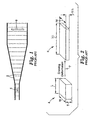
- Figure 1 illustrates a conventional tenter drawing process that stretches continuously fed films transversely to the direction of film travel.
- the film is gripped at both edges 2 by some gripping means, typically by tenter clips.
- the tenter clips are connected to tenter chains that ride along linearly diverging tenter tracks or rails. This arrangement propels the film forward in a machine direction of film travel and stretches the film. Thus an initial shape 4 in the film may be stretched to the shape 6.
- the ratio of the final T' to initial thickness of the film T may be defined as the normal direction draw ratio (NDDR).
- NDDR normal direction draw ratio
- MDDR machine direction draw ratio
- TDDR transverse direction draw ratio
- the NDDR is roughly the reciprocal of the TDDR in a conventional tenter, while the MDDR is essentially unchanged.
- This asymmetry in MDDR and NDDR draw causes differences in the various molecular, mechanical and optical properties of the film above and beyond the differences in properties between these directions and the stretch direction (TD).
- Illustrative examples of such properties include the crystal orientation and morphology, thermal and hygroscopic expansions, the small strain anisotropic mechanical compliances, tear resistance, creep resistance, shrinkage, the refractive indices and absorption coefficients at various wavelengths.
- U.S. Patent No. 4,862,564 discloses an apparatus for stretching a thermoplastic material web.
- the device includes an exponential or other curvilinear stretching profile.
- the apparatus provides a constant rate of stretch to the web, as opposed to the sharp peak and varying rate of stretch provided with conventional straight course tenter apparatus.
- Uniaxially drawn films have superior performance to simply monoaxially drawn films.
- uniaxially drawn films are more easily fibrillated or torn along the stretch direction (TD).
- TD stretch direction
- matching the MD and ND indices of refraction is often advantageous.
- U.S. Patent Nos. 5,882,774 ; 5,962,114 ; and 5,965,247 disclose materials with matched indexes of refraction for improved off-normal angle performance in brightness enhancement applications of multilayer reflective polarizers.
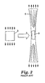
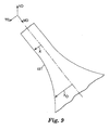
- Figure 3 illustrates a known batch technique for stretching a multilayer film suitable for use as a component in an optical device such as a polarizer.
- the flat, initial film 3 is stretched uniaxially in the direction of the arrows.
- the central portion necks down so that two edges of the film are no longer parallel after the stretching process.
- Much of the stretched film 5 is unusable as an optical component.
- Only a relatively small central portion 9 of the film is suitable for use in an optical component such as a polarizer. The yield and usable part size from this process are small.
- Japanese Unexamined Patent Publication Hei 5-11114 teaches that compensation films with matched MD and ND indices of refraction allow wider viewing angles in liquid crystalline displays.
- a conventional method for attempting to make a uniaxially drawn film is to use a length orienter (L.O.) that draws the film longitudinally in MD across at least one span between rollers of differing speed.
- the MDDR imparted along this span or draw gap is essentially the ratio of the speed of the downstream roll to the upstream roll. Because the film freely spans the rollers without edge constraints, the film can neck down in width as well as thin in caliper as it draws. Thus the TDDR can be reduced substantially below unity and can possibly be made to equal the NDDR.
- the method is fraught with difficulties and limitations.
- One disadvantage is the limitation on part size. An initial web of given width is reduced in width by a factor of the square root of the reciprocal of MDDR.
- a final film made with an L.O. has a substantially reduced width.
- the L.O. under uniaxial conditions reduces the possible part size substantially.
- Japanese Unexamined Patent Publication Hei 6-34815 points out another limitation of making films for optical applications over rollers. This document points out that rollers can scratch or otherwise damage the surface of the film. Films with delicate coatings or with soft skin layers could be easily deleteriously impacted.
- the method makes use of the MD tension that develops during draw to take up the slack of the corrugation and flatten the final film.
- the film is drawn normally and then placed in the waveform clips. Heat treatment under tension after draw and the resulting shrinkage forces are then relied on to flatten the web.
- the method is described in conjunction with polysulfone films at low levels of overfeed (under 20%). The method is likely limited by process issues such as the draw ratio range required and heat transfer. Many useful uniaxially oriented films require draw ratios in excess of 4. These in turn would require overfeeds in excess of 100%, resulting in deep out-of-plane folds that would be difficult to heat uniformly.
- the heat transfer to the tops and bottoms of the folds could be much higher than in the center plane due to the closer proximity to the heating plenums. This would tend to limit line speeds. Such large folds could also collapse and stick to each other as the web strength weakened in the pre-heat needed to effect draw, thereby causing the method to fail. At low levels of overfeed, the method reports good flattening across the film. As the boundary waveform became deeper, it is believed that the yield and quality of the final film would be adversely impacted.
- Japanese Unexamined Patent Publications, Hei 5-241021 , 6-51116 and 6-51119 disclose clip gripping surfaces remaining in-plane during draw.
- the film is fed into the clips at an out-of-plane angle while the clips are moving around an out-of-plane radius.
- the out-of-plane radius creates a temporary increase in the separation between the individual clips.
- the clip gripping surfaces return in-plane, the clips remain separated but more closely spaced, and corrugated portions of the film provide extra slack lie between the clips.
- the method relies on the tension during draw to flatten the film in-plane.
- the method may suffer the disadvantages of large corrugations for high draw ratio conditions.
- the edges of the film forming the initial corrugations are unsupported. As the drawing proceeds and stresses build, these unsupported edges begin to pull inwards towards the film centerline. Eventually large scallops form between the clips. The scallops not only make the edges unusable, but also create large caliper variations through the film. This adversely impacts the yield and quality of the final film.
- Hei 5-11113 discloses decoupling the MD line speed from the instantaneous film MD velocity by making the process partly discontinuous in mass flow. Transversely oriented slits are introduced into the web. These allow central portions of the otherwise continuous film to pull away from each other, allegedly allowing more substantially uniaxially drawn material in these portions. This method puts severe limits on usable part size and yield.
- U.S. Patent No. 4,349,500 discloses a film fed between two rotating disks or wheels.
- the film is gripped by two continuous belts.
- the film and the disks all lie in the same plane.
- the film stretches transversely between the counter rotating disks as its edges follow the diverging circumferential edges of the disks.
- the divergence angle of the draw becomes large, and the MD velocity of the film slows by the cosine of this divergence angle.
- the belt speed remains constant. In this manner, the output velocity is reduced from the input velocity of the film.
- the film is released from its gripping belts and the film is taken up at the slower MD velocity.
- the method discloses the adjustment of the separation distance between the centers of rotation of the disks and the size of the disks.
- One disadvantage of this method is the difficulty of maintaining good gripping of the film with the belt system. This would be particularly challenging in the stretching of films that develop high levels of drawing stress, e.g. polyesters drawn near their glass transition temperatures. It is believed that many materials used in this process would acquire a wrinkle or a non-uniaxially drawn permanent set using this method. For example, polyesters monoaxially drawn near their glass transitions while holding their MD lengths fixed may wrinkle rather than snap back in-plane when the final width is reduced in a succeeding step towards that anticipated for the substantially uniaxial case. Wrinkling also can occur when the MD reduction is applied too late in the TD drawing step.
- Swenson U.S. Patent No. 5,043,036 describes a canted wheel film drawing apparatus.
- the disks are no longer in-plane with the film and thus the sheet is stretched between out-of-plane boundary trajectories defined by the circumferences of the canted wheels.
- the method is described as a means of stretching films comprising elastomeric layers.
- U.S. Patent No. 3,807,004 due to the developing MD tension along the progress of the draw, stretching between such out-of-plane curved surfaces causes the film surface to become saddle shaped.
- the central portion of the film straightens out as it is not directly held, as is the film at the boundary trajectories, and thus it draws along a different path than the edges.
- This non-uniform drawing can result in significant caliper and property variations across the web, and is a major disadvantage for drawing films along boundary trajectories that move out-of-plane.
- U.S. Patent No. 3,807,004 described a variety of methods for partially dealing with the saddle formation.
- Profiling the initial film thickness or temperature distribution is suggested as a means to uniform caliper, although property variations due to different drawing histories would remain.
- a support device could force the film in the central portion to conform to the curved out-of-plane trajectory. Friction and concomitant damage to the film surface might be reduced by various methods including an air cushion.
- Saddling also manifests in various operations with the aforementioned disk orienter as described in U.S. Patent No. 4,434,128 .
- a convex guide surface is used to counter the saddling. Damage to the film surface from the application of such methods is another disadvantage to the method.
- films used in optical applications are particularly sensitive to surface defects as may be caused by scuffing and other contact-related defects.
- the present invention comprises processes for stretching film to provide desirable properties (e.g. optical properties), films stretched according to such processes and apparatus for stretching films.
- desirable properties e.g. optical properties
- the invention addresses shortcomings of the prior art such as excessive thickness deviation across the width of desired use of the final film, excessive anisotropic property deviation from fiber symmetry across the width of desired use of the final film, wrinkles and other non-flat imperfections in the final film, and surface contacting that can cause surface damage to the final film.
- the present invention includes a process for forming an optical film with predetermined optical properties, including the steps of providing a multilayer film having alternating layers of polymeric materials with predetermined optical properties, such that the film is defined in reference to a coordinate system of first and second orthogonal in-plane axes and a third mutually orthogonal axis in a thickness direction of the film; feeding the multilayer film to a stretcher; stretching the film along the first in-plane axis of the film with the stretcher while allowing contraction of the film in the second in-plane axis and in the thickness direction of the film, with the stretching achieved by grasping edge portions of the film and moving the edge portions of the film along predetermined paths which diverge to create substantially the same proportional dimensional changes in the second in-plane axis of the film and in the thickness direction of the film.
- the predetermined paths are shaped so as to create substantially the same proportional dimensional changes in the second in-plane axis of the film and in the thickness direction of the film. According to the present invention opposing edge portions of the film are moved along a predetermined paths that are substantially parabolic.
- the speed of the edge of the film is controlled to create substantially the same proportional dimensional changes in the second in-plane axis of the film and in the thickness direction of the film.
- At least one of the edge portions of the film is moved along a predetermined path at a substantially constant speed.
- the process is a continuous process and the film is fed continuously to the stretcher.
- the film may be fed continuously to the stretcher from a roll, or the film may be extruded or coextruded in-line with the stretcher.
- the strain rate along the stretch direction of the first in-plane axis is not constant during at least a portion of the stretch.
- the proportional dimensional changes in the second in-plane axis of the film and in the thickness direction of the film are substantially the same throughout substantially all of the draw history.
- the edge portions of the film move along predetermined paths that lie substantially within a plane defined by the first and second in-plane axes.
- the edge portions of the film move along a predetermined path that is three-dimensional.
- the edge portions of the film move along predetermined paths that are substantially symmetrical about a center axis.
- the film has first and second major surfaces and the film is stretched without physically contacting the first and second major surfaces of the film except at the edge portions of the film.
- a further example includes a process for forming film with predetermined properties, including the steps of providing a film that is defined in reference to a coordinate system of first and second orthogonal in-plane axes and a third mutually orthogonal axis in a thickness direction of the film; feeding the film to a stretcher; stretching the film along the first in-plane axis of the film with the stretcher while allowing contraction of the film in the second in-plane axis and in the thickness direction of the film, with the stretching accomplished by grasping edge portions of the film and moving edge portions of the film along predetermined paths that are shaped to create substantially the same proportional dimensional changes in the second in-plane axis of the film and in the thickness direction of the film throughout substantially all of the stretching step.
- the present invention includes a process for forming film with predetermined properties, including the steps of providing a film that is defined in reference to a coordinate system similar to that described above; feeding the film to a stretcher in a direction of travel of the film; stretching the film along the first in-plane axis of the film with the stretcher while allowing contraction of the film in the second in-plane axis and in the thickness direction of the film, with the stretching accomplished by grasping opposing edge portions of the film and moving the edge portions of the film along substantially parabolic paths that diverge.
- a further example includes a continuous process for forming film with predetermined properties, including the steps of providing a film that is defined in reference to a coordinate system similar to that described above; continuously feeding the film to a stretcher in a direction of travel of the film; stretching the film along the first in-plane axis of the film with the stretcher while allowing contraction of the film in the second in-plane axis and in the thickness direction of the film, with the stretching accomplished by grasping edge portions of the film and moving the edge portions of the film along predetermined paths that diverge in such a way that the strain rate in the direction of the first in-plane axis is not constant during at least a portion of the stretching step.
- a further example includes a roll of optical film with predetermined optical properties defined in reference to a coordinate system of first and second orthogonal in-plane axes and a third mutually orthogonal axis in a thickness direction of the film, such that the roll of optical film is constructed by the process of continuously feeding a roll of film to a stretcher and continuously stretching the film along the first in-plane axis of the film with the stretcher while allowing contraction of the film in the second in-plane axis and in the thickness direction of the film to create substantially the same proportional dimensional changes in the second in-plane axis of the film and in the thickness direction of the film.
- the roll of optical film is a multilayer optical film having alternating layers of polymeric materials having predetermined optical properties.
- the roll of optical film has portions suitable for being incorporated into a polarizer.
- the polarizer may be a reflective polarizer.
- the roll of film is constructed by the process of stretching the film so that substantially the same proportional dimensional changes in the second in-plane axis of the film and in the thickness direction of the film are created throughout substantially all of the stretching process.
- a further example relates to a stretcher for continuously processing film, including a means for receiving a continuous supply of film having predetermined properties, with the film being defined in reference to a coordinate system as described above; clamping means for grasping edge portions of the film; and stretching means for continuously moving the clamping means along predetermined paths that diverge so that the film is stretched along the transverse direction while allowing contraction of the film in the machine direction and the thickness direction, with the predetermined paths having shapes that are selected to create substantially the same proportional dimensional changes in the machine direction of the film and in the thickness direction of the film to impart predetermined optical properties into the film.
- the stretcher preferably includes a means for receiving a supply of the film which includes a means for receiving the film from a roll of said film.
- the stretcher also preferably includes take away means for removing the stretched film from the stretcher.
- the take away means includes means for severing the stretched film from rapidly diverging edge portions of the film and moving the stretched portion out of the stretcher.
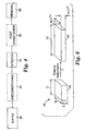
- Figure 4 is a block diagram of a process according to an aspect of the present invention. The process forms a film with predetermined properties.
- the present invention is applicable generally to a number of different films, materials and processes.
- the present invention is believed to be particularly suited to fabrication of polymeric optical films where the visco-elastic characteristics of materials used in the film are exploited to control the amount, if any, of molecular orientation induced in the materials when the film is drawn during processing.
- consideration of the various properties of the materials used to produce optical films may be exploited to improve the optical films.
- the improvements include one or more of improved optical performance, increased resistance to fracture or tear, enhanced dimensional stability, better processability and the like.
- optical films may be stretched or drawn according to the present invention.
- the films may comprise single or multi-layer films. Suitable films are disclosed, for example, in U.S. Patent Nos. 5,699,188 ; 5,825,543 ; 5,882,574 ; 5,965,247 ; 6,096,375 ; and PCT Publication Nos. WO 95/17303 ; WO 96/19347 ; WO 99/36812 ; WO 99/36248 . These films can be drawn to stretch ratios in excess of 4. In some embodiments, the films are drawn to stretch ratios in excess of 5, in excess of 6, in excess of 6.5, or in excess of 7.
- Films made in accordance with the present invention may be useful for a wide variety of products including polarizers, reflective polarizers, dichroic polarizers, aligned reflective/dichroic polarizers, absorbing polarizers, retarders (including z-axis retarders).
- the films may comprise the optical element itself or they can be used as a component in an optical element such as matched z-index polarizers used in beamsplitters for front and rear projection systems, or as a brightness enhancement film used in a display or microdisplay.
- the stretcher described below in accordance with the present invention may be used with a length orienter to make a mirror from a multi-layer optical film.
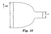
- FIG. 9 A process for fabricating an optical film in accordance with one particular embodiment of the present invention will be described with reference to Figures 9 , 10 and 11 .
- Figures 9 , 10 and 11 These figures illustrate a portion of an optical film.
- the depicted optical film may be described with reference to three mutually orthogonal axes TD, MD and ND.
- two orthogonal axes TD and MD are in the plane of the film (in-plane axes) and a third axis extends in the direction of the film thickness.
- FIG. 4 is a block diagram of a process according to the present invention.
- the film is supplied or provided to an apparatus for stretching the film.
- the process may optionally include a preconditioning step 32.
- the film is stretched in step 34.
- the film may optionally be post-conditioned in step 36.
- the film is removed from the stretching apparatus in step 38.
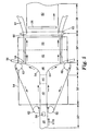
- Figure 5 illustrates a preferred embodiment of the invention.
- the process includes the step of providing a film 40 to a stretching apparatus (see region 30').
- the film may be referred to with reference to a coordinate system of first and second orthogonal in-plane axes (e.g. machine direction MD and transverse direction TD) and a third mutually orthogonal axis in a thickness direction of the film (e.g. normal direction ND).
- the process includes the steps of feeding the film 40 to a stretcher (see region 30'); stretching the film along the first in-plane axis of the film with the stretcher while allowing contraction of the film in the second in-plane axis and in the thickness direction of the film (see region 34'), with the stretching achieved by grasping edge portions of the film and moving the edge portions of the film along predetermined paths 64 which diverge to create substantially the same proportional dimensional changes in the second in-plane axis of the film and in the thickness direction of the film.
- the process may optionally include a preconditioning step (see region 32') such as providing an oven 54 or other apparatus.
- the preconditioning step may include a preheating zone (see region 42 of the film) and a heat soak zone (see region 44).
- the film is stretched in region 34'. Edges of the film may be grasped by mechanical clips that are moved by rollers 62 in the direction of the arrows.
- paths 64 are parabolic or substantially parabolic.
- the process includes an optional post-conditioning step (see region 36').
- the film may be set in region 48 and quenched in region 50.
- a belt and rollers may optionally be used to progress the film in this region.
- a cut may be made at 58 and flash or unusable portion 56 may be discarded.
- the rapidly diverging edge portions 56 are preferably severed from the stretched film 48 at a slitting point 58.
- release of the selvages from a continuous gripping mechanism can be done continuously; however, release from discrete gripping mechanisms, such as tenter clips, should be done over discrete MD section of the film, e.g. all the material under any given clip is released at once. This discrete release mechanism may cause larger upsets in stress that may be felt by the drawing web upstream.
- a continuous selvage separation mechanism in the device, e.g. the "hot" slitting of the selvage from the central portion of a heated, drawn film.
- the slitting location is preferably located near enough to the "gripline", e.g. the isolating takeaway point of first effective gripper contact, to minimize stress upsets upstream of that point. If the film is slit before the gripping, instable takeaway can result, e.g. by film "snapback" along TD.
- the film is thus preferably slit at or downstream of the gripline. Slitting is a fracture process and, as such, typically has a small but natural variation in spatial location. Thus it may be preferred to slit slightly downstream of the gripline to prevent any temporal variations in slitting from occurring upstream of the gripline.
- the film between the takeaway and boundary trajectory will continue to stretch along TD. Since only this portion of the film is now drawing, it now draws at an amplified draw ratio relative to the boundary trajectory, creating further stress upsets that could propagate upstream, e.g. undesirable levels of machine direction tension propagating upstream.
- the slitting is preferably mobile and re-positionable so that it can vary with the changes in takeaway positions needed to accommodate variable final transverse draw direction ratio.
- An advantage of this type of slitting system is that the draw ratio can be adjusted while maintaining the draw profile simply by moving the take-away slitting point 58.
- a variety of slitting techniques may be used included a heat razor, a hot wire, a laser, a focused beam of intense IR radiation or a focused jet of heated air.
- the heated jet of air the air may be sufficiently hotter in the jet to blow a hole in the film, e.g. by heat softening, melting and controlled fracture under the jet.
- the heated jet may merely soften a focused section of the film sufficiently to localize further drawing imposed by the still diverging boundary trajectories, thus causing eventual fracture downstream along this heated line through the action of continued film extension.
- the focused jet approach may be preferred in some cases, especially when the exhaust air can be actively removed, e.g.
- a vacuum exhaust in a controlled fashion to prevent stray temperature currents from upsetting the uniformity of the drawing process.
- a concentric exhaust ring around the jet nozzle may be used.
- an exhaust underneath the jet, e.g. on the other side of the film, may be used.
- the exhaust may be further offset or supplemented downstream to further reduce stray flows upstream into the drawing zone.
- the process also includes a removal portion in region 38'.
- a roller 65 may be used to advance the film, but this may be eliminated.
- the roller 65 is not used as it would contact the stretched film 52 with the attendant potential to damage the stretched film.
- Another cut 60 may be made and unused portion 61 may be discarded.
- Figure 6 helps illustrate what is meant in this application when it is said that the process "creates substantially the same proportional dimensional changes in the second in-plane axis of the film and in the thickness direction of the film".
- Three dimensional element 24 represents an unstretched portion of film (see e.g. Figures 5 and 6 ) with dimensions T, W and L.
- Three dimensional element 26 represents element 24 after it has been stretched a length lambda. As can be seen in Figure 6 , the thickness and width have been reduced by the same proportional dimensional changes.
- Figure 6 represents a uniaxial stretch, as opposed, for example, to the non-uniaxial stretch shown in Figure 2 .
- the present invention is not limited to perfect uniaxial stretching. Instead, the present invention includes processes, apparatus and films that are "substantially" uniaxially stretched. The following discussion and observations are provided to defme what is within the scope of the present invention.
- substantially uniaxially drawn films preferably possess fiber symmetry in which the properties in MD and ND are similar within a given material layer (as films comprising multiple layers may not themselves possess fiber symmetry due to the layered natured of the film composite). This may exist in an elastic material when two of the draw ratios are equal. When one of the directions, e.g. TD, is stretched, then the other two directions, e.g. MD and ND, preferably have equal draw ratios. Assuming volume conservation, the MDDR and NDDR both should approach the square root of the reciprocal of the TDDR. Films drawn in a conventional tenter are not substantially uniaxially drawn even though they have been physically drawn in only one direction (so-called "monoaxial" drawing) because the boundary constraints of the process impart differences between MDDR and NDDR.
- the present invention is also not limited to those processes that stretch film under uniaxial conditions throughout the entire history of the stretch or draw.
- the present invention addresses the inadequacy of prior art processes (e.g. the disk orienters) to provide the substantially uniaxial constraint on machine direction draw ratio (MDDR) and transverse direction draw ratio (TDDR) throughout the entire history of the draw.
- MDDR machine direction draw ratio
- TDDR transverse direction draw ratio
- the failure of the prior art to provide the uniaxial condition throughout the draw is a cause of wrinkling and other out-of-plane defects in the final film.
- the present invention provides a process in which a substantially uniaxial draw is provided via the boundary trajectories throughout the drawing step. More preferably, the process provides this history dependence while maintaining the film in-plane.
- the stretching step need not be performed within a substantially planar region (as depicted in Figure 5 ). As discussed in more detail below, it is within the present invention to provide a boundary trajectory of the film that is three dimensional and substantially non-planar.
- the present invention maintains the deviation from a uniaxial draw within certain tolerances throughout the various portions of the drawing step.
- the present invention may maintain these conditions while deforming a portion of the film out-of-plane in an initial portion of the draw, but return the film in-plane during a final portion of the draw.
- the instantaneous MDDR equals the square root of the reciprocal of the TDDR.
- the film may be drawn out-of-plane using out-of-plane boundary trajectories, i.e. boundary trajectories that do not lie in a single Euclidean plane.
- boundary trajectories meeting relational requirements of this preferred embodiment of the present invention, so that a substantially uniaxial draw history may be maintained using out-of-plane boundary trajectories.
- the boundaries may be symmetrical, forming mirror images through a central plane, e.g. a plane comprising the initial center point between the boundary trajectories, the initial direction of film travel and the initial normal to the unstretched film surface.
- the film may be drawn between the boundary trajectories along a cylindrical space manifold formed by the set of line segments of shortest distance between the two opposing boundary trajectories as one travels along these boundary trajectories at equal rates of speed from similar initial positions, i.e., colinear with each other and the initial center point.
- the trace of this ideal manifold on the central plane thus traces out the path of the film center for an ideal draw.
- the ratio of the distance along this manifold from the boundary trajectory to this central trace on the central plane to the original distance from the start of the boundary trajectory to the initial center point is the instantaneous nominal TDDR across the film spanning the boundary trajectories, i.e. the ratios of the half-distances between the current opposing points on the boundary trajectories and the half-distances between the initial positions of the opposing points on the boundary trajectories.
- the corresponding center point on the central trace changes speed as measured along the arc of the central trace, i.e. the curvilinear MD.
- the central trace changes in proportion with the projection of the unit tangent of the boundary trajectory on the unit tangent of the central trace.
- Uniaxial draw may be maintained along the entire history of the draw as long as the speed of the central point reduces at every point along the central trace from its initial speed by a factor of exactly the square root of the reciprocal of the instantaneous TDDR measured between the corresponding opposing points on the opposing boundary trajectories.
- This is the uniaxial condition when viewing the instantaneous MDDR of a differential film arc along the idealized central trace.
- the uniaxial condition may be achieved by controlling the ratio of the instantaneous rate of change of arc length along the central trace to the instantaneous rate of change of arc length at a corresponding opposing point on a boundary trajectory, i.e. the curvilinear MDDR.
- the film is drawn in plane such as shown in Figure 5 .
- the design of the boundary trajectories is also simplified because the in-plane constraint reduces the number of variables.
- the design of the boundary trajectory may proceed by considering the instantaneous in-plane draw ratios MDDR and TDDR rather than the MDDR or MD speed as defined along the curvilinear central trace. The result is a pair of mirror symmetric in-plane parabolic trajectories diverging away from the in-plane MD centerline between them.
- the parabola may be portrayed by first defining the TD as the "x" direction and the MD as the "y” direction.
- the MD centerline between the opposing bounding parabolas may be taken as the y coordinate axis.
- the left bounding parabolic trajectory is obtained by multiplying the left-hand side of the above equation 1 by minus unity.
- Equation 1 provides the uniaxial condition. As such it represents the in-plane drawing state in which MD tension should be negligible.
- the principal axes of molecular orientation and of the resulting properties as induced by the draw preferably remain nearly constant. In this case, straight lines drawn along TD, the principal draw direction, remain substantially straight after drawing. In tenter processing of biaxially oriented films, this is typically not the case.
- the present invention is not limited to perfectly uniaxially drawn films.
- nearly or "substantially" uniaxially drawn films are sufficient to make components of sufficient desired properties.
- the uniformity of such films is more important than the precise manifestation of uniaxial character.
- a discrepancy in uniaxial character in properties such as refractive index is tolerable in many applications.
- the off-angle characteristics of reflective polarizers used in liquid crystalline display applications is strongly impacted by the difference in the MD and ND indices of refraction when TD is the principal mono-axial draw direction.
- An index difference in MD and ND at 633 nm of 0.08 may be acceptable in some applications.
- a difference of 0.04 is allowable in others.
- preferred embodiments of films according to the present invention include the class of nearly or substantially uniaxially drawn films, processes for creating such substantially uniaxially drawn films and apparatus for creating such substantially uniaxially drawn films.
- a preferred method for calculating trajectories within a specified envelope of nearly or substantially uniaxial character is discussed.
- the method determines the "right" boundary trajectory directly, and the "left" boundary trajectory is taken as a mirror image.
- the envelope constraint is set by defining an instantaneous functional relationship between TDDR measured between the opposing boundary trajectories and the MDDR defined as the cosine of the non-negative divergence angle of those boundary trajectories, over a chosen range of TDDR.
- the geometry of the problem is defined as described in the discussion of the parabolic trajectories.
- X 1 is defined as the initial half width between the boundary trajectories and ratio (x/x 1 ) is identified as the instantaneous TDDR, where x is the current x position of an opposing point on the boundary trajectory.
- the instantaneous functional relationship between the TDDR and MDDR is converted to a relationship between TDDR and the divergence angle.
- the differential equation may be solved, e.g. by integrating 1/tan( ⁇ ) along the history of the TDDR, (x/x1), from unity to the maximum desired value to obtain the complete coordinate set ⁇ (x,y) ⁇ of the right boundary trajectory, either analytically or numerically.
- the divergence angle is the non-negative, smallest angle made between the direction of travel of the centerline of the film and the instantaneous boundary trajectory at (x,y).
- the travel of the center line is along MD, e.g. the divergence angle is zero, when the boundary trajectories are parallel to MD, as is nearly the case in a conventional tenter.
- the method of a preferred embodiment of the present invention is illustrated by way of the parabolic trajectory example.
- First the envelope is chosen as the uniaxial constraint.
- the TDDR is shown to equal the square of the reciprocal of the cosine of the divergence angle.
- the TDDR is equal to the square of the tangent of the divergence angle plus unity. This allows direct substitution of the left-hand side of the equation by a function of TDDR only.
- the equation can then be analytically integrated to discover the result, equation 1.
- U 1 / MDDR - 1 / TDDR 1 / 2 - 1
- the extent of uniaxial character of 0.85 is sufficient in many cases to provide an index of refraction difference between the MD and ND directions in polyester systems comprising polyethylene naphthalate of 0.02 or less at 633 nm for mono-axially transverse drawn films.
- the extent of uniaxial character can be at least 0.9 or 0.95 or higher.
- Equation 3 provides a specific relationship between MDDR and TDDR which, when coupled with the aforementioned algorithm or method, specifies a broader class of boundary trajectories that also includes the parabolic trajectories as a limiting case when U approaches unity. Trajectories that exhibit values of U below unity for at least a final portion of the draw are referred to herein as sub-parabolic trajectories.
- This class of trajectories is a preferred approximation to constant U for TDDR under 8.
- the class of trajectories described above are illustrative and should not be construed as limiting. A host of trajectory classes are considered to lie within the scope of the present invention.
- the present invention preferably encompasses all nearly uniaxial boundary trajectories comprising a minimum value of U of about 0.70, more preferably approximately 0.75, still more preferably about 0.80 and even more preferably about 0.85.
- the minimum U constraint may be applied over a final portion of the draw defined by a critical TDDR preferably of about 2.5, still more preferably about 2.0 and more preferably about 1.5.
- the critical TDDR can be 4 or 5.
- certain materials e.g.
- certain monolithic and multilayer films comprising orientable and birefringent polyesters, may begin to lose their elasticity or capability of snap back, e.g. because of the development of structure such as strain-induced crystallinity.
- the TDDR may coincide with a variety of material and process (e.g. temperature and strain rate) specific events such as the critical TDDR for the onset of strain-induced crystallization.
- the minimum value of U above such a critical TDDR could relate to an amount of non-uniaxial character set into the final film.
- the amount of such MD tension increases with decreasing U.
- U may be taken as a non-increasing function with TDDR, as opposed to a prior art disk orienter that decreases U with TDDR.
- the parabolic trajectory assumes a uniform spatial drawing of the film.
- Good spatial uniformity of the film may be achieved with many polymeric systems with careful control of the crossweb and downweb caliper (thickness) distribution of the initial, undrawn film or web, coupled with the careful control of the temperature distribution at the start of and during the draw.
- a uniform temperature distribution across the film initially and during draw on a film of initially uniform caliper should suffice in most cases.
- Many polymeric systems are particularly sensitive to non-uniformities and will draw in a non-uniform fashion if caliper and temperature uniformity are inadequate.
- polypropylenes tend to "line draw" under mono-axial drawing.
- Certain polyesters, notably polyethylene naphthalate are also very sensitive.
- the invention includes means for gripping the film, preferably the edges of the film.
- the film is sandwiched between gripper faces on a mechanical clip assembly.
- the effective edge of the gripper face where the film is no longer effectively held defines the edge of the central portion of the film that will be drawn.
- This gripper edge defmes a boundary edge for the drawing film.
- the motion of the gripper may also define a boundary trajectory that is, at least in part, responsible for the motion and drawing of the film (while other effects, e.g., downweb tension and take-up devices, may account for the rest of the motion and drawing.).
- the gripper face edges are designed so that the center of the edge measured along one clip instantaneously follows the tangent of a chain riding along a rail or inside a channel cut into the rail.
- the boundary trajectory may also be defined by the rail when offset of the gripper edge face from the rail channel are included.
- the effective edge of the gripper face can be somewhat obscured by slight film slippage from or flow out from under the faces, but these deviations can be made small. Since the film is held by two sets of opposing grippers mounted on pairs of chains and rails, there are two opposing boundary trajectories. Preferably, these trajectories are mirror images about the MD center line of the drawing film.
- the rails are traditionally formed by a series of straight segments whose angle of divergence, e.g. the angle formed between the boundary trajectories and the direction of film travel (e.g. MD), may be adjusted. Curved trajectories have also been explored.
- the means for gripping the film according to the present invention may be discrete or continuous in nature.
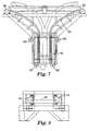
- Figures 7 and 8 illustrate details of a preferred embodiment of an apparatus for stretching films according to an aspect of the present invention.
- the gripping means comprise a series of tenter clips 70 that afford overall flexibility via segmentation.
- the discrete clips 70 are closely packed and attached to a flexible structure such as a chain.
- the flexible structure rides along or in channels along the trajectory control device, such as a rail. Strategically placed cams and cam surfaces open and close the tenter clips at desired points.
- the clip and chain assembly may optionally ride on wheels or bearings or the like.
- the continuous gripping mechanism may comprise a flexible and continuous mechanism, such as a belt or tread.
- the flexible and continuous mechanism may nest or ride in a groove or a channel.
- Preferred continuous gripping mechanisms provide the advantage of continuously following the changing boundary trajectories along every portion of the boundary edge.
- Segmented, discrete gripping systems are within the present invention and tend to only approximate the boundary trajectory along portions of the film at the boundary edges.
- a tenter clip has a straight clip face edge. The clip is mounted so that the center of this clip face edge remains tangent to the boundary trajectory, e.g. tangent to the tenter rail, throughout the course of travel and draw. This means that the film gripped at the center does follow the boundary trajectory; however, the rest of the film gripped along the rest of the clip is constrained to a path deviating from the boundary trajectory, unless the boundary trajectory is straight.
- the film, at the edge, gripped by single clip would otherwise tend to exhibit the divergence angle at the clip center along the whole distance of the clip.
- film upstream of the clip face edge center would tend to have too large of a divergence angle relative to the intended boundary trajectories
- film downstream of the clip face edge center would tend to have too small of a divergence angle relative to the intended boundary trajectories.
- a small MD fluctuation in the film properties and uniaxial characteristics may develop. In practice, these MD fluctuations may be maintained small by using short enough clips for a given device.
- the length of a clip face edge may preferably be no more that one-half, and more preferably no more than one-quarter, the total initial distance between the boundary trajectories. Smaller clips will in general provide better approximations to the boundary trajectories and smaller MD fluctuations.
- Precise control of the divergence angle actually manifested by the gripper mechanism is a design consideration because it is the divergence angle that contributes to setting the condition for MDDR compatibility with the edge.
- the interactions of the stress field of the film with the boundaries may also tend to moderate approximation errors at the edges as one proceeds towards the film MD centerline. It may be useful in some case to reduce the gripper contact to less than the total length of the clip.
- the film in between two sequential clips experiences a condition of under-approximated divergence angle from the leading edge of the upstream clip to over-approximated divergence angle from the trailing edge of the downstream clip.
- a slight relaxation of the contact areas at these edges could reduce sharp variations in MDDR and alleviate undesired stress fields that could cause defects. Loss of gripper action at a portion of the edge may be carefully balanced to reduce undue scalloping at the unsupported edge.
- the stretcher apparatus may direct airflow towards or into the boundary edge, e.g. to have air exhaust through the gripper region to improve heat transfer to the drawable film near the gripper faces.
- the apparatus may optionally apply active cooling to the gripper mechanism, e.g. to the clips, to maintain good gripping of the gripped portion of the film, e.g. by preventing flow out from under the gripper mechanism.
- active heating and cooling will help to establish the effective boundary edge region.
- the boundary edge be reasonably approximated by the gripper face edges or by a small offset from these towards the film centerline.
- the boundary trajectories may be fixed or adjustable.
- the underlying control of the boundary trajectories may be like the rails, a moving surface or some other means of support for a discrete or continuous system.
- the rails may also be segmented and adjustable in part or as a whole. For example, adjustment of the rails or underlying support for a belt system could be made either at junctions or by physical bending, and by various means.
- the driving means can be any number of methods. For example, it can be the motion of the chain as propelled by gears connected to a drive, or the motion of the belt by an independent drive or by the motion of the underlying support, e.g. the disk in a disk orienter.
- the means of release can be either a physical release of the selvages held by the gripping means or a physical separation of the selvages from a central portion of the drawn film.
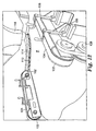
- Figure 12 illustrates a preferred take away means 100.
- the take away means comprises belts 104 and wheels 102.
- the takeaway means may include drive wheel 108 and adjustment arms 106.
- the takeaway means takes hold of at least a portion of the released film while preferably preventing damage to the usable portion of the film.
- the take-away device preferably provides a means of support while a heated film F quenches.
- the takeaway may also preferably comprise a means for controlling shrinkage in either the TD or MD direction or both. Film leaving the takeaway device is typically wound on rolls for later use. Alternatively, direct converting may take place after take away.
- the take-away means may comprise any number of methods including a simple roller system with nips, wrap angles, vacuum assists, and the like.
- a system comprising a top and bottom masking system such as a cover film lamination system may be included. This would protect the surface from the action of a roller system.
- Another attribute of the take-away system is a method of speed and or MD tension control so that the film can be removed in a manner compatible with the output speed.
- This take-away system could also be used to pull out any residual wrinkles in the film. The wrinkles could be initially pulled out during start up by a temporary increase in the takeaway speed above the output speed of the final, released portion of the drawn film, or the wrinkles could be pulled out by a constant speed above the output film speed during continuous operation.
Claims (16)
- Verfahren zum Verarbeiten eines Films, wobei das Verfahren Folgendes umfasst:Transportieren eines Films in einer Streckvorrichtung entlang einer Maschinenrichtung, während die einander gegenüberliegenden Kantenteile des Films gehalten sind; undStrecken des Films in der Streckvorrichtung durch Bewegen der einander gegenüberliegenden Kantenteile entlang divergierender, im Wesentlichen parabolischer Bahnen, um einen gestreckten Film zu bilden.
- Verfahren nach Anspruch 1, wobei das Strecken des Films das Strecken des Films bis zu einem Reckverhältnis von mehr als vier in der Streckvorrichtung durch Bewegen der einander gegenüberliegenden Kantenteile entlang divergierender, im Wesentlichen parabolischer Bahnen umfasst, um einen gestreckten Film zu bilden.
- Verfahren nach Anspruch 1, wobei das Strecken des Films das Strecken des Films unter nicht konstanter Belastung in der Streckvorrichtung durch Bewegen der einander gegenüberliegenden Kantenteile entlang divergierender, im Wesentlichen parabolischer Bahnen umfasst, um einen gestreckten Film zu bilden.
- Verfahren nach Anspruch 1, wobei der Film eine Anfangsdicke und Anfangsbreite hat, wenn er in die Streckvorrichtung transportiert wird und der gestreckte Film eine gestreckte Dicke und eine gestreckte Breite hat; und
wobei nach dem Strecken des Films bis zu einem Verhältnis der gestreckten Breite/Anfangsbreite, das als λ definiert ist, ein Verhältnis der gestreckten Dicke/Anfangsdicke ca. λ-1/2 ist. - Verfahren nach Anspruch 1, wobei der Schritt des Streckens des Films das Strecken des Films in der Streckvorrichtung durch Bewegen der einander gegenüberliegenden Kantenteile entlang divergierender, im Wesentlichen parabolischer Bahnen umfasst, wobei die Bahnen koplanar sind.
- Verfahren nach Anspruch 1, wobei der Schritt des Streckens des Films das Strecken des Films in der Streckvorrichtung durch Bewegen der gegenüberliegenden Kantenteile entlang divergierender, im Wesentlichen parabolischer Bahnen umfasst, wobei die Bahnen im Wesentlichen symmetrisch zu einer Mittelachse des Films sind.
- Verfahren nach Anspruch 1, das ferner das Bereitstellen des Films für die Streckvorrichtung in einer kontinuierlichen Weise von einer Filmrolle umfasst.
- Verfahren nach Anspruch 1, das ferner das Extrudieren oder Koextrudieren des Films in Reihe mit der Streckvorrichtung umfasst.
- Verfahren nach Anspruch 1, wobei der gestreckte Film mindestens eine Schicht mit Brechungsindizes in einer Längsrichtung umfasst, die der Maschinenrichtung entspricht, und einer Dickenrichtung, die im Wesentlichen dieselbe ist, aber sich im Wesentlichen von einem Brechungsindex in einer Breitenrichtung unterscheidet.
- Verfahren nach Anspruch 1, das ferner das Lösen der Kantenteile des Films an einem Ende der im Wesentlichen parabolischen Bahnen umfasst.
- Verfahren nach Anspruch 1, wobei der Mindestwert des Maßes von uniaxialem Charakter, U, mindestens 0,7 beträgt, wobei U folgendermaßen definiert ist:

wobei MDDR das Reckverhältnis in der Maschinenrichtung ist und TDDR das Reckverhältnis in der Querrichtung ist. - Verfahren nach Anspruch 1, wobei die divergierenden, im Wesentlichen parabolischen Bahnen eine funktionelle Form haben:

wobei eine x-Achse in einer Ebene des Films und orthogonal zur Maschinenrichtung definiert ist, mit x=0 in einer Mittelachse des Films, eine y-Achse in der Ebene des Films und entlang der Maschinenrichtung mit y=0 definiert ist, wo das Strecken des Films innerhalb der Streckvorrichtung beginnt und x0 eine Entfernung der Kantenteile von der Mittelachse des Films ist, wenn y=0 ist. - Verfahren nach Anspruch 1, wobei zumindest ein Teil der divergierenden, im Wesentlichen parabolischen Bahnen eine funktionelle Form hat:

wobei eine x-Achse in einer Ebene des Films und orthogonal zur Maschinenrichtung definiert ist, mit x=0 in einer Mittelachse des Films, eine y-Achse in der Ebene des Films und entlang der Maschinenrichtung mit y=0 definiert ist, wo das Strecken des Films innerhalb der Streckvorrichtung beginnt, c eine beliebige Zahl ist und x1 eine Entfernung der Kantenteile von der Mittelachse des Films ist, wenn y=0 ist. - Verfahren nach Anspruch 1, wobei die einander gegenüberliegenden Kantenteile des Films im Wesentlichen kontinuierlich gestützt sind.
- Verfahren nach einem der Ansprüche 1 bis 14, wobei der Film ein mehrschichtiger Film ist, der abwechselnde Schichten verschiedener Polymerzusammensetzungen umfasst.
- Verfahren nach Anspruch 15, wobei der mehrschichtige optische Film ein im Wesentlichen uniaxial ausgerichteter mehrschichtiger Film ist.
Priority Applications (1)
| Application Number | Priority Date | Filing Date | Title |
|---|---|---|---|
| EP11175254.9A EP2394805A3 (de) | 2001-05-31 | 2002-05-29 | Verfahren und Vorrichtung zur Herstellung von quer gezogenen Filmen mit im Wesentlichen einachsiger Ausrichtung |
Applications Claiming Priority (3)
| Application Number | Priority Date | Filing Date | Title |
|---|---|---|---|
| US29494001P | 2001-05-31 | 2001-05-31 | |
| US294940P | 2001-05-31 | ||
| PCT/US2002/017148 WO2002096621A2 (en) | 2001-05-31 | 2002-05-29 | Processes and apparatus for making transversely drawn films with substantially uniaxial orientation |
Related Child Applications (2)
| Application Number | Title | Priority Date | Filing Date |
|---|---|---|---|
| EP11175254.9A Division EP2394805A3 (de) | 2001-05-31 | 2002-05-29 | Verfahren und Vorrichtung zur Herstellung von quer gezogenen Filmen mit im Wesentlichen einachsiger Ausrichtung |
| EP11175254.9 Division-Into | 2011-07-25 |
Publications (2)
| Publication Number | Publication Date |
|---|---|
| EP1526961A2 EP1526961A2 (de) | 2005-05-04 |
| EP1526961B1 true EP1526961B1 (de) | 2011-10-26 |
Family
ID=23135569
Family Applications (4)
| Application Number | Title | Priority Date | Filing Date |
|---|---|---|---|
| EP10180145.4A Expired - Lifetime EP2277682B1 (de) | 2001-05-31 | 2002-05-29 | Verfahren und Vorrichtung zur Herstellung von quer gestreckten Filmen mit im Wesentlichen einachsiger Ausrichtung |
| EP02737292A Expired - Lifetime EP1526961B1 (de) | 2001-05-31 | 2002-05-29 | Verfahren zum herstellen von quer gestreckten folien mit wesentlich uniaxialer orientierung |
| EP11175254.9A Withdrawn EP2394805A3 (de) | 2001-05-31 | 2002-05-29 | Verfahren und Vorrichtung zur Herstellung von quer gezogenen Filmen mit im Wesentlichen einachsiger Ausrichtung |
| EP02737255.6A Expired - Lifetime EP1390193B1 (de) | 2001-05-31 | 2002-05-29 | Vorrichtung zum herstellen von quer gestreckten folien mit wesentlich uniaxialer orientierung |
Family Applications Before (1)
| Application Number | Title | Priority Date | Filing Date |
|---|---|---|---|
| EP10180145.4A Expired - Lifetime EP2277682B1 (de) | 2001-05-31 | 2002-05-29 | Verfahren und Vorrichtung zur Herstellung von quer gestreckten Filmen mit im Wesentlichen einachsiger Ausrichtung |
Family Applications After (2)
| Application Number | Title | Priority Date | Filing Date |
|---|---|---|---|
| EP11175254.9A Withdrawn EP2394805A3 (de) | 2001-05-31 | 2002-05-29 | Verfahren und Vorrichtung zur Herstellung von quer gezogenen Filmen mit im Wesentlichen einachsiger Ausrichtung |
| EP02737255.6A Expired - Lifetime EP1390193B1 (de) | 2001-05-31 | 2002-05-29 | Vorrichtung zum herstellen von quer gestreckten folien mit wesentlich uniaxialer orientierung |
Country Status (9)
| Country | Link |
|---|---|
| US (6) | US6916440B2 (de) |
| EP (4) | EP2277682B1 (de) |
| JP (5) | JP2005501757A (de) |
| KR (1) | KR100866176B1 (de) |
| CN (1) | CN100374282C (de) |
| AT (1) | ATE530329T1 (de) |
| AU (1) | AU2002310230A1 (de) |
| TW (2) | TW548176B (de) |
| WO (2) | WO2002096621A2 (de) |
Families Citing this family (146)
| Publication number | Priority date | Publication date | Assignee | Title |
|---|---|---|---|---|
| US6916440B2 (en) * | 2001-05-31 | 2005-07-12 | 3M Innovative Properties Company | Processes and apparatus for making transversely drawn films with substantially uniaxial character |
| US6936209B2 (en) * | 2002-11-27 | 2005-08-30 | 3M Innovative Properties Company | Methods and devices for processing polymer films |
| US6949212B2 (en) * | 2002-11-27 | 2005-09-27 | 3M Innovative Properties Company | Methods and devices for stretching polymer films |
| US6938309B2 (en) * | 2002-12-13 | 2005-09-06 | 3M Innovative Properties Company | Zoned stretching of a web |
| US20040227994A1 (en) * | 2003-05-16 | 2004-11-18 | Jiaying Ma | Polarizing beam splitter and projection systems using the polarizing beam splitter |
| JP2005157292A (ja) * | 2003-10-27 | 2005-06-16 | Sekisui Chem Co Ltd | 位相差フィルムの製造方法 |
| AU2004289539C1 (en) | 2003-11-14 | 2012-06-07 | Lorus Therapeutics Inc. | Aryl imidazoles and their use as anti-cancer agents |
| JP2005181450A (ja) | 2003-12-16 | 2005-07-07 | Nitto Denko Corp | 複屈折フィルムの製造方法、およびそれを用いた光学フィルムおよび画像表示装置 |
| US7234816B2 (en) | 2004-02-03 | 2007-06-26 | 3M Innovative Properties Company | Polarizing beam splitter assembly adhesive |
| TW200532290A (en) * | 2004-03-30 | 2005-10-01 | Optimax Tech Corp | Manufacturing method of optical thin film |
| JP2006133720A (ja) | 2004-10-07 | 2006-05-25 | Nitto Denko Corp | 複屈折フィルムの製造方法、およびそれを用いた光学フィルム、液晶パネル、液晶表示装置、画像表示装置 |
| JP2006133719A (ja) * | 2004-10-07 | 2006-05-25 | Nitto Denko Corp | 位相差フィルム一体型偏光板及び位相差フィルム一体型偏光板の製造方法 |
| US7710511B2 (en) * | 2004-10-15 | 2010-05-04 | 3M Innovative Properties Company | Liquid crystal displays with laminated diffuser plates |
| US7446827B2 (en) * | 2004-10-15 | 2008-11-04 | 3M Innovative Properties Company | Direct-lit liquid crystal displays with laminated diffuser plates |
| US7345137B2 (en) | 2004-10-18 | 2008-03-18 | 3M Innovative Properties Company | Modified copolyesters and optical films including modified copolyesters |
| US7749411B2 (en) * | 2004-12-01 | 2010-07-06 | Konica Minolta Opto, Inc. | Optical film and production method of the same |
| US20060138702A1 (en) * | 2004-12-23 | 2006-06-29 | Biernath Rolf W | Method of making uniaxially oriented articles having structured surfaces |
| US7315418B2 (en) * | 2005-03-31 | 2008-01-01 | 3M Innovative Properties Company | Polarizing beam splitter assembly having reduced stress |
| US20060221447A1 (en) * | 2005-03-31 | 2006-10-05 | 3M Innovative Properties Company | Stabilized polarizing beam splitter assembly |
| US9709700B2 (en) | 2005-04-06 | 2017-07-18 | 3M Innovative Properties Company | Optical bodies including rough strippable boundary layers |
| JP2008537794A (ja) * | 2005-04-06 | 2008-09-25 | スリーエム イノベイティブ プロパティズ カンパニー | 配向可能なポリマーブレンドを備えた拡散反射型偏光フィルム |
| EP1890869B1 (de) * | 2005-04-06 | 2008-10-15 | 3M Innovative Properties Company | Optische körper mit rauen abziehbaren grenzschichten und asymmetrischen oberflächenstrukturen |
| JP2008537797A (ja) * | 2005-04-06 | 2008-09-25 | スリーエム イノベイティブ プロパティズ カンパニー | 特定の機能層を有する光学フィルムを備えた光学体 |
| US20060227421A1 (en) * | 2005-04-06 | 2006-10-12 | Stover Carl A | Optical bodies including strippable boundary layers |
| KR101287740B1 (ko) * | 2005-04-08 | 2013-07-18 | 쓰리엠 이노베이티브 프로퍼티즈 컴파니 | 광학 필름의 열 경화법 |
| WO2006113380A1 (en) * | 2005-04-18 | 2006-10-26 | 3M Innovative Properties Company | Multifunctional thick film reflective polarizer for displays |
| US7385763B2 (en) * | 2005-04-18 | 2008-06-10 | 3M Innovative Properties Company | Thick film multilayer reflector with tailored layer thickness profile |
| US8148392B2 (en) | 2005-05-25 | 2012-04-03 | Lorus Therapeutics Inc. | 2-indolyl imidazo [4,5-d] phenanthroline derivatives and their use in the treatment of cancer |
| US20060272766A1 (en) * | 2005-06-03 | 2006-12-07 | Hebrink Timothy J | Optical bodies and method of making optical bodies including acrylate blend layers |
| US20060291055A1 (en) * | 2005-06-15 | 2006-12-28 | 3M Innovative Properties Company | Diffuse Multilayer Optical Article |
| US7537374B2 (en) | 2005-08-27 | 2009-05-26 | 3M Innovative Properties Company | Edge-lit backlight having light recycling cavity with concave transflector |
| US7815355B2 (en) | 2005-08-27 | 2010-10-19 | 3M Innovative Properties Company | Direct-lit backlight having light recycling cavity with concave transflector |
| KR101298786B1 (ko) | 2005-08-27 | 2013-08-22 | 쓰리엠 이노베이티브 프로퍼티즈 컴파니 | 조명 조립체 및 시스템 |
| US20070047080A1 (en) * | 2005-08-31 | 2007-03-01 | 3M Innovative Properties Company | Methods of producing multilayer reflective polarizer |
| WO2007032513A1 (en) * | 2005-09-12 | 2007-03-22 | Fujifilm Corporation | Method for producing cellulose acylate film, polarizing plate and liquid crystal display |
| TWI406754B (zh) * | 2005-09-21 | 2013-09-01 | Fujifilm Corp | 聚合物薄膜之製法 |
| US7924368B2 (en) * | 2005-12-08 | 2011-04-12 | 3M Innovative Properties Company | Diffuse multilayer optical assembly |
| US7686453B2 (en) * | 2005-12-19 | 2010-03-30 | 3M Innovative Properties Company | High contrast liquid crystal display and projection system using same |
| US7673993B2 (en) * | 2005-12-22 | 2010-03-09 | 3M Innovative Properties Company | Projection system using reflective polarizers |
| US7475991B2 (en) * | 2005-12-22 | 2009-01-13 | 3M Innovative Properties Company | Polarizing beamsplitter assembly |
| US7369320B2 (en) | 2005-12-30 | 2008-05-06 | 3M Innovative Properties Company | Projection system with beam homogenizer |
| US20070153402A1 (en) * | 2005-12-30 | 2007-07-05 | Destain Patrick R | Fresnel lens combination |
| US7798678B2 (en) * | 2005-12-30 | 2010-09-21 | 3M Innovative Properties Company | LED with compound encapsulant lens |
| US20070228586A1 (en) * | 2006-03-31 | 2007-10-04 | Merrill William W | Process for making an optical film |
| US20070231548A1 (en) * | 2006-03-31 | 2007-10-04 | Merrill William W | Process for making an optical film and rolls of optical film |
| US20070242197A1 (en) * | 2006-04-12 | 2007-10-18 | 3M Innovative Properties Company | Transflective LC Display Having Backlight With Spatial Color Separation |
| US20070247573A1 (en) * | 2006-04-19 | 2007-10-25 | 3M Innovative Properties Company | Transflective LC Display Having Narrow Band Backlight and Spectrally Notched Transflector |
| US20070264578A1 (en) * | 2006-05-15 | 2007-11-15 | Tonen Chemical Corporation | Microporous polyolefin membrane, its production method and battery separator |
| US20070292680A1 (en) * | 2006-06-12 | 2007-12-20 | Fujifilm Corporation | Optical film, production method of optical film, polarizing plate and liquid crystal display device |
| US9134471B2 (en) | 2006-06-28 | 2015-09-15 | 3M Innovative Properties Company | Oriented polymeric articles and method |
| JP5330993B2 (ja) * | 2006-07-31 | 2013-10-30 | スリーエム イノベイティブ プロパティズ カンパニー | 光学投影サブシステム |
| TW200815709A (en) * | 2006-07-31 | 2008-04-01 | 3M Innovative Properties Co | Integrating light source module |
| US20080036972A1 (en) * | 2006-07-31 | 2008-02-14 | 3M Innovative Properties Company | Led mosaic |
| EP2372797A3 (de) | 2006-07-31 | 2017-01-18 | 3M Innovative Properties Co. | Leuchtdiode-Quelle mit konkaver Sammellinse |
| US8075140B2 (en) | 2006-07-31 | 2011-12-13 | 3M Innovative Properties Company | LED illumination system with polarization recycling |
| US20080030656A1 (en) * | 2006-08-01 | 2008-02-07 | 3M Innovative Properties Company | Transflective lc display with internal reflector and reflective polarizer |
| JP5676104B2 (ja) | 2006-09-29 | 2015-02-25 | スリーエム イノベイティブ プロパティズ カンパニー | ポリマーベースの光学素子におけるアーチファクトの生成を抑制する接着剤 |
| US20080083998A1 (en) * | 2006-10-06 | 2008-04-10 | 3M Innovative Properties Company | Multiple draw gap length orientation process |
| US20080083999A1 (en) * | 2006-10-06 | 2008-04-10 | 3M Innovative Properties Company | Process for making an optical film |
| US20080085383A1 (en) * | 2006-10-06 | 2008-04-10 | 3M Innovative Properties Company | Processes for improved optical films |
| US20080085481A1 (en) * | 2006-10-06 | 2008-04-10 | 3M Innovative Properties Company | Rolls of optical film |
| US20080206381A1 (en) * | 2007-02-23 | 2008-08-28 | Nexcel Synthetics, Llc | Methods and systems for manufacturing yarns for synthetic turf |
| US9770611B2 (en) | 2007-05-03 | 2017-09-26 | 3M Innovative Properties Company | Maintenance-free anti-fog respirator |
| US20080271739A1 (en) | 2007-05-03 | 2008-11-06 | 3M Innovative Properties Company | Maintenance-free respirator that has concave portions on opposing sides of mask top section |
| US8857033B2 (en) * | 2008-02-04 | 2014-10-14 | Illinois Tool Works Inc. | Oriented package combination for a molded elastomeric product |
| CA2720466A1 (en) * | 2008-05-09 | 2009-11-12 | Juergen Dorn | Method of loading a stent into a sheath |
| GB0815339D0 (en) * | 2008-08-21 | 2008-10-01 | Angiomed Ag | Method of loading a stent into a sheath |
| CN102265088B (zh) | 2008-11-19 | 2015-02-18 | 3M创新有限公司 | 用于照明设备和其他照明系统中的光管理的布鲁斯特角膜 |
| JP5662332B2 (ja) | 2008-11-19 | 2015-01-28 | スリーエム イノベイティブ プロパティズ カンパニー | 極方向及び方位方向の両方における出力制限を有する多層光学フィルム並びに関連する構成 |
| CN102282014B (zh) | 2008-11-19 | 2015-01-21 | 3M创新有限公司 | 在极角和方位角方向均具有输出限制的反射膜组合及相关构造 |
| US8792165B2 (en) | 2008-12-22 | 2014-07-29 | 3M Innovative Properties Company | Internally patterned multilayer optical films with multiple birefringent layers |
| JP5371523B2 (ja) * | 2009-04-14 | 2013-12-18 | 東芝機械株式会社 | フィルム延伸装置およびフィルムの延伸方法 |
| GB0921237D0 (en) | 2009-12-03 | 2010-01-20 | Angiomed Ag | Stent device delivery system and method of making such |
| GB0921240D0 (en) | 2009-12-03 | 2010-01-20 | Angiomed Ag | Stent device delivery system and method of making such |
| GB0921238D0 (en) | 2009-12-03 | 2010-01-20 | Angiomed Ag | Stent device delivery system and method of making such |
| GB0921236D0 (en) | 2009-12-03 | 2010-01-20 | Angiomed Ag | Stent device delivery system and method of making such |
| US9102131B2 (en) | 2010-03-26 | 2015-08-11 | 3M Innovative Properties Company | Textured film and process for manufacture thereof |
| KR101842416B1 (ko) | 2010-05-27 | 2018-03-26 | 쓰리엠 이노베이티브 프로퍼티즈 컴파니 | 닙 롤의 속도 제어를 사용해 필름을 압출 코팅하는 동안에 결함을 제거하는 방법 |
| AU2011280094B2 (en) | 2010-06-30 | 2014-04-17 | 3M Innovative Properties Company | Multi-layer articles capable of forming color images and methods of forming color images |
| US9097858B2 (en) | 2010-06-30 | 2015-08-04 | 3M Innovative Properties Company | Retarder film combinations with spatially selective birefringence reduction |
| US9069136B2 (en) | 2010-06-30 | 2015-06-30 | 3M Innovative Properties Company | Optical stack having birefringent layer of optically symmetrical crystallites |
| KR101851813B1 (ko) | 2010-06-30 | 2018-06-11 | 쓰리엠 이노베이티브 프로퍼티즈 컴파니 | 공간 선택적 복굴절 감소를 갖는 필름을 사용하는 마스크 처리 |
| WO2012012180A2 (en) | 2010-06-30 | 2012-01-26 | 3M Innovative Properties Company | Light directing film |
| WO2012003123A1 (en) | 2010-06-30 | 2012-01-05 | 3M Innovative Properties Company | Multilayer optical film |
| US9939560B2 (en) | 2010-06-30 | 2018-04-10 | 3M Innovative Properties Company | Diffuse reflective optical films with spatially selective birefringence reduction |
| CA2804150C (en) | 2010-06-30 | 2018-02-06 | 3M Innovative Properties Company | Multi-layer articles capable of forming color images and methods of forming color images |
| GB201020373D0 (en) | 2010-12-01 | 2011-01-12 | Angiomed Ag | Device to release a self-expanding implant |
| KR101994490B1 (ko) | 2010-12-10 | 2019-06-28 | 쓰리엠 이노베이티브 프로퍼티즈 컴파니 | 눈부심 감소 창유리 물품 |
| US9138031B2 (en) | 2011-02-16 | 2015-09-22 | 3M Innovative Properties Company | Method of making a mechanical fastening strip and reticulated mechanical fastening strip therefrom |
| SG194102A1 (en) | 2011-04-08 | 2013-11-29 | 3M Innovative Properties Co | Light duct tee extractor |
| CN102267230B (zh) * | 2011-07-30 | 2013-05-01 | 江阴中绿化纤工艺技术有限公司 | 横拉机 |
| US20130070080A1 (en) * | 2011-09-16 | 2013-03-21 | Toray Plastics (America), Inc. | High speed tenter chain inspection system |
| CN103796824B (zh) * | 2011-09-20 | 2015-11-25 | 3M创新有限公司 | 纹理膜及制造方法 |
| US9081147B2 (en) | 2012-01-03 | 2015-07-14 | 3M Innovative Properties Company | Effective media retarder films with spatially selective birefringence reduction |
| EP3284365B1 (de) | 2012-05-16 | 2020-01-01 | 3M Innovative Properties Co. | Verfahren zur herstellung eines mechanischen befestigungselements mit balliger oberfläche |
| ES2643559T3 (es) | 2012-05-16 | 2017-11-23 | 3M Innovative Properties Company | Método de fabricación de un dispositivo de fijación mecánica usando discos divergentes |
| CN104321040B (zh) | 2012-05-18 | 2017-03-08 | 3M创新有限公司 | 制备机械紧固件的方法以及包括具有突起的辊的设备 |
| US9211481B2 (en) * | 2012-07-27 | 2015-12-15 | Nb Tech Inc. | Visual display system and method of constructing a high-gain reflective beam-splitter |
| US10539717B2 (en) * | 2012-12-20 | 2020-01-21 | Samsung Sdi Co., Ltd. | Polarizing plates and optical display apparatuses including the polarizing plates |
| JP2016516082A (ja) | 2013-03-20 | 2016-06-02 | アプトース バイオサイエンシーズ, インコーポレイテッド | 2−置換イミダゾ[4,5−d]フェナントロリン誘導体及び癌の治療におけるそれらの使用 |
| US9314962B2 (en) * | 2013-05-10 | 2016-04-19 | 3M Innovative Properties Company | Method of separating strands on a stretching surface |
| CN105473188B (zh) | 2013-07-15 | 2020-06-05 | 3M创新有限公司 | 具有光学活性呼气阀的呼吸器 |
| USD746974S1 (en) | 2013-07-15 | 2016-01-05 | 3M Innovative Properties Company | Exhalation valve flap |
| US9864120B2 (en) | 2013-09-05 | 2018-01-09 | 3M Innovative Properties Company | Patterned marking of multilayer optical film by thermal conduction |
| WO2015037527A1 (ja) * | 2013-09-10 | 2015-03-19 | 東洋紡株式会社 | 液晶表示装置、偏光板及び偏光子保護フィルム |
| DK3052102T3 (da) | 2013-10-04 | 2020-03-09 | Aptose Biosciences Inc | Sammensætninger til behandling af cancere |
| US9841598B2 (en) | 2013-12-31 | 2017-12-12 | 3M Innovative Properties Company | Lens with embedded multilayer optical film for near-eye display systems |
| US10642044B2 (en) | 2014-04-09 | 2020-05-05 | 3M Innovative Properties Company | Near-eye display system having a pellicle as a combiner |
| KR20150137705A (ko) * | 2014-05-30 | 2015-12-09 | 삼성전자주식회사 | 필름 제조 장치 및 방법 |
| MX2017006889A (es) | 2014-12-01 | 2017-09-01 | Dow Global Technologies Llc | Películas de contracción, y métodos para su fabricación. |
| CA2969426A1 (en) | 2014-12-01 | 2016-06-09 | Dow Global Technologies Llc | Polymer compositions, shrink films, and methods of making thereof |
| US10037850B2 (en) | 2014-12-18 | 2018-07-31 | 3M Innovative Properties Company | Multilayer film capacitor |
| JP6306272B2 (ja) | 2014-12-22 | 2018-04-04 | スリーエム イノベイティブ プロパティズ カンパニー | ポリマーフィルムを延伸及び取り出しするための装置及び方法 |
| GB201508114D0 (en) | 2015-05-12 | 2015-06-24 | 3M Innovative Properties Co | Respirator tab |
| CN107801385B (zh) | 2015-06-30 | 2021-02-12 | 陶氏环球技术有限责任公司 | 沿机器方向定向的多层薄膜和包括所述薄膜的物品 |
| KR102454570B1 (ko) | 2015-06-30 | 2022-10-13 | 니폰 제온 가부시키가이샤 | 장척 필름 및 그 제조 방법 |
| JP6834957B2 (ja) | 2015-07-10 | 2021-02-24 | 日本ゼオン株式会社 | 液晶表示装置 |
| US9599761B1 (en) | 2015-09-03 | 2017-03-21 | 3M Innovative Properties Company | Thermoformed multilayer reflective polarizer |
| US11022734B2 (en) | 2016-05-26 | 2021-06-01 | 3M Innovative Properties Company | Polarizer stack |
| US11016229B2 (en) | 2016-06-09 | 2021-05-25 | 3M Innovative Properties Company | Optical filter |
| KR20190018550A (ko) | 2016-07-12 | 2019-02-22 | 쓰리엠 이노베이티브 프로퍼티즈 컴파니 | 광학 스택 |
| US11231536B2 (en) | 2016-08-16 | 2022-01-25 | 3M Innovative Properties Company | Polarizer |
| JP7101182B2 (ja) | 2016-11-15 | 2022-07-14 | スリーエム イノベイティブ プロパティズ カンパニー | 光学レンズ及び光学レンズを含むアイウェア |
| US10754073B2 (en) | 2016-11-29 | 2020-08-25 | 3M Innovative Properties Company | Optical stack having reflective polarizer with polymeric layers and specified reflectance and transmittance |
| WO2018116080A1 (en) | 2016-12-20 | 2018-06-28 | 3M Innovative Properties Company | Optical system |
| TW201832916A (zh) | 2016-12-28 | 2018-09-16 | 日商日本瑞翁股份有限公司 | 視角放大薄膜、偏光板及液晶顯示裝置 |
| EP3593180A1 (de) | 2017-03-06 | 2020-01-15 | 3M Innovative Properties Company | Optische folie mit hohem kontrast und vorrichtungen damit |
| US11156757B2 (en) | 2017-03-06 | 2021-10-26 | 3M Innovative Properties Company | High contrast optical film and devices including the same |
| CN110506228B (zh) | 2017-03-31 | 2021-12-14 | 3M创新有限公司 | 光学系统 |
| WO2018184911A1 (en) | 2017-04-03 | 2018-10-11 | Tata Steel Ijmuiden B.V. | Process for producing a polymer coated metal substrate and a metal strip substrate provided with a polymer coating |
| US11262565B2 (en) | 2017-05-16 | 2022-03-01 | 3M Innovatipve Properties C Ompany | Optical system |
| CN110799332B (zh) | 2017-06-26 | 2021-12-21 | 3M创新有限公司 | 包括具有低透光轴变化的多层双折射反射型偏振器的卷膜 |
| JP7387591B2 (ja) | 2017-06-26 | 2023-11-28 | スリーエム イノベイティブ プロパティズ カンパニー | 多層複屈折反射偏光子及びポリビニルアルコール層を含み、通過軸のバラツキが小さいフィルムのロール |
| EP3651887A4 (de) | 2017-07-14 | 2021-04-14 | 3M Innovative Properties Company | Adapter zum fördern mehrerer flüssigkeitsströme |
| JP2020537194A (ja) | 2017-10-09 | 2020-12-17 | スリーエム イノベイティブ プロパティズ カンパニー | 光学構成要素及び光学システム |
| CN111316146B (zh) | 2017-10-10 | 2022-06-03 | 3M创新有限公司 | 弯曲的反射偏振膜及其成形方法 |
| US11846773B2 (en) | 2017-10-27 | 2023-12-19 | 3M Innovative Properties Company | Optical system |
| CN113927879A (zh) | 2017-10-27 | 2022-01-14 | 3M创新有限公司 | 成形光学膜、使光学膜成形的方法和弯曲反射偏振器 |
| KR20200096914A (ko) | 2017-10-30 | 2020-08-14 | 압토스 바이오사이언시스 인코포레이티드 | 암 치료용 아릴 이미다졸 |
| DE102018101455A1 (de) * | 2018-01-23 | 2019-07-25 | Brückner Maschinenbau GmbH & Co. KG | Vorrichtung zum mono- oder biaxialen Recken von Kunststoffmaterialabschnitten |
| JP6695373B2 (ja) * | 2018-03-15 | 2020-05-20 | 住友化学株式会社 | 延伸フィルムの製造方法 |
| WO2019220377A1 (en) | 2018-05-18 | 2019-11-21 | 3M Innovative Properties Company | Shaped optical film |
| JP7466516B2 (ja) | 2018-07-13 | 2024-04-12 | スリーエム イノベイティブ プロパティズ カンパニー | 光学システム及び光学フィルム |
| WO2020035791A1 (en) | 2018-08-14 | 2020-02-20 | 3M Innovative Properties Company | Optical system |
| CN112585506A (zh) | 2018-08-15 | 2021-03-30 | 3M创新有限公司 | 包括微透镜阵列的光学元件 |
| US11597198B2 (en) | 2020-10-05 | 2023-03-07 | Meta Platforms Technologies, Llc | Methods of manufacturing optically anisotropic polymer thin films |
Family Cites Families (125)
| Publication number | Priority date | Publication date | Assignee | Title |
|---|---|---|---|---|
| NL68942C (de) * | 1940-07-25 | |||
| US2618012A (en) | 1948-05-14 | 1952-11-18 | American Viscose Corp | Method and apparatus for two-way stretching a continuous sheet |
| US2823421A (en) * | 1952-05-12 | 1958-02-18 | Du Pont | Stretching of polyethylene terephthalate film |
| US2998772A (en) | 1955-09-02 | 1961-09-05 | William E Land | Plastic bonded explosives rocket warhead |
| NL253923A (de) * | 1959-07-25 | |||
| US3055048A (en) * | 1959-11-12 | 1962-09-25 | American Viscose Corp | Simultaneous blaxial stretching of film with a tenter frame |
| NL258465A (de) * | 1960-03-16 | 1900-01-01 | ||
| GB905252A (en) * | 1960-04-04 | 1962-09-05 | Plastic Textile Access Ltd | Improvements in and relating to the stretching of plastic net for molecular orientation of the mesh strands |
| NL120720C (de) | 1960-12-24 | |||
| US3296351A (en) * | 1961-08-11 | 1967-01-03 | Phillips Petroleum Co | Method of producing a lateral stretching of a continuous sheet material |
| US3142108A (en) * | 1961-11-16 | 1964-07-28 | Dornier Gmbh Lindauer | Tenter chain mechanism |
| DE1504502B2 (de) * | 1962-03-17 | 1971-08-12 | Lindauer Dormer GmbH, 8990 Lin dau | Reckanlage zum biaxialen recken einer thermoplastischen kunststoffolienbahn |
| US3110927A (en) * | 1962-04-13 | 1963-11-19 | Avisun Corp | Film stretching apparatus |
| DE1259558B (de) | 1962-07-28 | 1968-01-25 | Dornier Gmbh Lindauer | Vorrichtung zum gleichzeitigen biaxialen Recken von Kunststoffolienbahnen |
| DE1206575B (de) | 1963-05-21 | 1965-12-09 | Henschel Werke Ag | Vorrichtung zum Recken von Kunststoffolienbahnen gleichzeitig in Laengs- und Querrichtung |
| JPS4113634Y1 (de) | 1964-10-03 | 1966-06-27 | ||
| US3502766A (en) | 1965-01-28 | 1970-03-24 | Nippon Rayon Kk | Process for the improvement of polyamide films |
| US3432894A (en) * | 1967-12-19 | 1969-03-18 | Joh Sons Kleinewerfers | Fabric stretching device |
| US3577586A (en) | 1967-12-20 | 1971-05-04 | Johnson & Johnson | Apparatus for continuously transversely stretching orientable sheet material |
| ES391123A1 (es) | 1970-05-19 | 1974-05-01 | Hoechst Ag | Procedimiento y aparato para el estiramiento de laminas de material sintetico termoplastico. |
| US4134957A (en) * | 1970-10-26 | 1979-01-16 | Toyobo Co., Ltd. | Method of stretching polypropylene films |
| DE2110625C3 (de) * | 1971-03-05 | 1980-09-04 | Willi Johann 6204 Taunusstein Schmidt | Verfahren zum Breitstrecken von Kunststoff-Folienbahnen |
| US3985600A (en) * | 1971-07-09 | 1976-10-12 | Consolidated-Bathurst Limited | Method for slitting a film |
| FR2147876B1 (de) | 1971-08-05 | 1974-03-29 | Cellophane Sa | |
| DE2356743C3 (de) * | 1973-11-14 | 1978-06-08 | Hoechst Ag, 6000 Frankfurt | Verfahren und Vorrichtung zur Verbesserung der Griffsicherheit von Spannkluppen zur führenden Halterung von Folienbahnrändern während eines Querstreckprozesses |
| JPS5577530A (en) | 1978-12-08 | 1980-06-11 | Polymer Processing Res Inst | Method of producing film uniaxially stretched in widthwise direction |
| DE2853398C3 (de) | 1978-12-11 | 1981-09-17 | Unilever N.V., Rotterdam | Verfahren und Vorrichtung zum simultanen biaxialen Recken einer Folienbahn aus Kunststoff |
| JPS55126427A (en) | 1979-03-22 | 1980-09-30 | Polymer Processing Res Inst | Lateral stretching device for film and fibrous material |
| JPS5649223A (en) | 1979-09-27 | 1981-05-02 | Kobe Steel Ltd | Method and device for transversely stretching film |
| JPS5649226A (en) | 1979-09-28 | 1981-05-02 | Toyobo Co Ltd | Manufacturing of thermoshrinking polyamide film |
| JPS57163532A (en) | 1981-04-01 | 1982-10-07 | Polymer Processing Res Inst | Method for orienting film to traverse direction mainly |
| JPS58219024A (ja) * | 1982-06-15 | 1983-12-20 | Polymer Processing Res Inst | 膜・繊維材の延伸方法並びに装置 |
| JPS59185630A (ja) * | 1983-04-06 | 1984-10-22 | Mitsubishi Heavy Ind Ltd | フイルム等帯状物の横延伸倍率制御方法 |
| JPS60103089U (ja) | 1983-12-20 | 1985-07-13 | 株式会社 吉川製作所 | ブレ−キレバ−のレバ−部構造 |
| JPS61227019A (ja) | 1985-04-02 | 1986-10-09 | Polymer Processing Res Inst | 皮膜の横延伸方法及び装置 |
| US4624940A (en) | 1985-04-12 | 1986-11-25 | Engelhard Corporation | High temperature catalyst compositions for internal combustion engine |
| US4577586A (en) * | 1985-05-02 | 1986-03-25 | Morris Fredric H | Automatic ski waxing machine |
| JPH0511114Y2 (de) | 1985-06-07 | 1993-03-18 | ||
| JPS62135338A (ja) | 1985-12-09 | 1987-06-18 | Diafoil Co Ltd | 液晶パネル基板用ポリエチレンナフタレ−ト一軸高配向フイルム |
| JPS62134244A (ja) | 1985-12-09 | 1987-06-17 | Toray Ind Inc | ポリエステルフイルムの熱処理方法 |
| US4853602A (en) * | 1985-12-24 | 1989-08-01 | E. I. Dupont De Nemours And Company | System for using synchronous secondaries of a linear motor to biaxially draw plastic films |
| FR2593434B1 (fr) | 1986-01-29 | 1988-07-15 | Extrusion Calandrage Ste Fse | Mecanisme d'etirage transversal et en continu d'un film plastique |
| JPH0651119B2 (ja) | 1986-03-04 | 1994-07-06 | 株式会社佐竹製作所 | 米粒加圧加湿装置 |
| JPS62263023A (ja) | 1986-05-12 | 1987-11-16 | Teijin Ltd | 熱可塑性樹脂フイルムの弛緩熱処理法 |
| JPS62268629A (ja) | 1986-05-19 | 1987-11-21 | Teijin Ltd | 熱可塑性樹脂フイルムの熱処理方法 |
| JPH0831012B2 (ja) | 1987-08-20 | 1996-03-27 | 株式会社日立製作所 | データ検証試験方法 |
| US4862564A (en) | 1987-11-09 | 1989-09-05 | Mobil Oil Corporation | Apparatus for stretching a thermoplastic material web |
| JPH0627321Y2 (ja) | 1988-02-15 | 1994-07-27 | 株式会社クラタ産業 | 研磨工具 |
| JPH0643321Y2 (ja) | 1988-03-03 | 1994-11-09 | 株式会社ヤマデ | ポリマー改質アスファルトルーフィング |
| US5004649A (en) | 1988-04-13 | 1991-04-02 | Idemitsu Kosan Co., Ltd. | Resin laminates and a process for production thereof |
| US5296080A (en) * | 1988-04-19 | 1994-03-22 | Paper Converting Machine Company | Apparatus for applying an elastic waistband to a disposable diaper |
| US5000806A (en) * | 1988-04-19 | 1991-03-19 | Paper Converting Machine Company | Method and apparatus for applying an elastic strand to a disposable diaper |
| US5072493A (en) | 1988-06-22 | 1991-12-17 | E. I. Du Pont De Nemours And Company | Apparatus for drawing plastic film in a tenter frame |
| JPH0830765B2 (ja) | 1988-09-26 | 1996-03-27 | 富士写真フイルム株式会社 | 位相差フイルムの製造方法 |
| JPH0634815Y2 (ja) | 1988-12-12 | 1994-09-14 | ウシオ電機株式会社 | 空気浄化装置 |
| JPH0429827Y2 (de) | 1989-01-11 | 1992-07-20 | ||
| JPH089883B2 (ja) | 1989-06-08 | 1996-01-31 | ミサワホーム株式会社 | 陸梁の施工方法 |
| JPH03124426A (ja) | 1989-10-09 | 1991-05-28 | Teijin Chem Ltd | フイルムの延伸方法 |
| DE3936345C1 (de) | 1989-11-02 | 1991-03-07 | Man Roland Druckmaschinen Ag, 6050 Offenbach, De | |
| JPH03182701A (ja) | 1989-12-13 | 1991-08-08 | Nippon Kayaku Co Ltd | 延伸フィルム及びその製造法 |
| JPH0643097B2 (ja) | 1990-03-27 | 1994-06-08 | ダイアホイルヘキスト株式会社 | 二軸配向ポリエステルフィルムの製造方法 |
| US5043036A (en) * | 1990-03-30 | 1991-08-27 | Minnesota Mining And Manufacturing Company | Width stretching device |
| JPH03284934A (ja) | 1990-03-31 | 1991-12-16 | Diafoil Co Ltd | 二軸配向ポリエステルフィルムの製造方法 |
| JPH0429827A (ja) | 1990-05-28 | 1992-01-31 | Hitachi Ltd | シート状物の同時二軸延伸装置 |
| JPH04113634A (ja) | 1990-09-03 | 1992-04-15 | Matsushita Electric Ind Co Ltd | 半導体装置の製造方法 |
| JPH0511113A (ja) | 1991-07-05 | 1993-01-19 | Sekisui Chem Co Ltd | 位相差板の製造方法 |
| JPH0511114A (ja) | 1991-07-08 | 1993-01-19 | Sekisui Chem Co Ltd | 位相差板の製造方法 |
| JPH05150115A (ja) | 1991-11-28 | 1993-06-18 | Sekisui Chem Co Ltd | 位相差板の製造方法 |
| JPH05241021A (ja) | 1992-02-27 | 1993-09-21 | Sekisui Chem Co Ltd | 位相差フィルムの製造方法 |
| JPH05288932A (ja) | 1992-04-07 | 1993-11-05 | Sekisui Chem Co Ltd | 位相差板の製造方法 |
| JPH05288931A (ja) | 1992-04-07 | 1993-11-05 | Sekisui Chem Co Ltd | 位相差板の製造方法 |
| JPH0627321A (ja) | 1992-07-13 | 1994-02-04 | Sekisui Chem Co Ltd | 位相差板の製造方法 |
| JPH0634815A (ja) | 1992-07-15 | 1994-02-10 | Sekisui Chem Co Ltd | 位相差フィルムの製造方法 |
| US5215334A (en) * | 1992-07-23 | 1993-06-01 | Presson Ronald C | Emergency medical card |
| JPH0643321A (ja) | 1992-07-24 | 1994-02-18 | Sekisui Chem Co Ltd | 位相差フィルムの製造方法 |
| JPH0651119A (ja) | 1992-07-28 | 1994-02-25 | Sekisui Chem Co Ltd | 位相差板の製造方法 |
| JPH0651116A (ja) | 1992-07-31 | 1994-02-25 | Sekisui Chem Co Ltd | 位相差フィルムの製造方法 |
| CA2177714C (en) | 1993-12-21 | 2005-08-09 | Andrew J. Ouderkirk | Multilayered optical film |
| US5882774A (en) * | 1993-12-21 | 1999-03-16 | Minnesota Mining And Manufacturing Company | Optical film |
| US6096375A (en) | 1993-12-21 | 2000-08-01 | 3M Innovative Properties Company | Optical polarizer |
| CA2125807A1 (en) * | 1994-03-14 | 1995-09-15 | Edward Heerman Ruscher | Apparatus and method for stretching an elastomeric material in a cross machine direction |
| US5517737A (en) * | 1994-06-06 | 1996-05-21 | The Procter & Gamble Company | Apparatus for continuously stretching or continuously releasing stretching forces from a web using two pairs of opposing non-planar belts |
| NL9400844A (nl) * | 1994-05-24 | 1996-01-02 | Boschman Holding Bv | Werkwijze en inrichting voor het ommantelen van voorwerpen. |
| WO1997024216A1 (fr) * | 1994-07-01 | 1997-07-10 | Nippon Petrochemicals Company, Limited | Dispositif servant a etendre transversalement un corps en forme de bande |
| JP2999379B2 (ja) | 1994-10-11 | 2000-01-17 | 帝人株式会社 | 延伸フィルムの弛緩熱処理方法 |
| US5717737A (en) * | 1995-06-01 | 1998-02-10 | Padcom, Inc. | Apparatus and method for transparent wireless communication between a remote device and a host system |
| EP0778477B1 (de) | 1995-06-23 | 2002-10-02 | The Furukawa Electric Co., Ltd. | Lichtrefletkierende platte |
| CN1106937C (zh) * | 1995-06-26 | 2003-04-30 | 美国3M公司 | 带有附加涂层或附加层的多层聚合物薄膜 |
| US5699188A (en) | 1995-06-26 | 1997-12-16 | Minnesota Mining And Manufacturing Co. | Metal-coated multilayer mirror |
| US5783120A (en) * | 1996-02-29 | 1998-07-21 | Minnesota Mining And Manufacturing Company | Method for making an optical film |
| US5825543A (en) * | 1996-02-29 | 1998-10-20 | Minnesota Mining And Manufacturing Company | Diffusely reflecting polarizing element including a first birefringent phase and a second phase |
| BR9707766A (pt) * | 1996-02-29 | 1999-07-27 | Minnesota Mining & Mfg | Corpo ótico |
| US5867316A (en) * | 1996-02-29 | 1999-02-02 | Minnesota Mining And Manufacturing Company | Multilayer film having a continuous and disperse phase |
| JPH116905A (ja) | 1997-06-16 | 1999-01-12 | Nitto Denko Corp | 光拡散フィルムおよびその製法 |
| US5885501A (en) * | 1997-06-24 | 1999-03-23 | E. I. Du Pont De Nemours And Company | Process for preparing dimensionally stabilized biaxially stretched thermoplastic film |
| US5771547A (en) * | 1997-08-14 | 1998-06-30 | E.I. Du Pont De Nemours And Company | Tenter clip cleaning method and apparatus |
| US5882574A (en) | 1997-10-14 | 1999-03-16 | Owens-Brockway Plastic Products Inc. | Injection extrusion blow molding process for making multiple compartment plastic containers |
| US6113811A (en) * | 1998-01-13 | 2000-09-05 | 3M Innovative Properties Company | Dichroic polarizing film and optical polarizer containing the film |
| US6179948B1 (en) | 1998-01-13 | 2001-01-30 | 3M Innovative Properties Company | Optical film and process for manufacture thereof |
| EP2147771B1 (de) | 1998-01-13 | 2018-07-11 | Minnesota Mining And Manufacturing Company | Verfahren zur Herstellung mehrschichtiger optischer Filme |
| US6788463B2 (en) * | 1998-01-13 | 2004-09-07 | 3M Innovative Properties Company | Post-formable multilayer optical films and methods of forming |
| US6111697A (en) * | 1998-01-13 | 2000-08-29 | 3M Innovative Properties Company | Optical device with a dichroic polarizer and a multilayer optical film |
| US6531230B1 (en) * | 1998-01-13 | 2003-03-11 | 3M Innovative Properties Company | Color shifting film |
| GB9803848D0 (en) * | 1998-02-25 | 1998-04-22 | Ici Ltd | Multi-layer polymer films |
| ITTO980580A1 (it) | 1998-07-02 | 2000-01-02 | C R F Societa Consotile Per Az | Dispositivo emettitore di luce, a base di materiale organico elettro- luminescente, con interfaccia esterna conformata |
| CA2338348A1 (en) | 1998-07-31 | 2000-02-10 | Minnesota Mining And Manufacturing Company | Post-formable multilayer optical films and methods of forming |
| US6358457B1 (en) | 1998-11-13 | 2002-03-19 | 3M Innovative Properties Company | Method of stretching films according to an overbias or overstretch profile |
| JP2000162419A (ja) | 1998-11-26 | 2000-06-16 | Toyobo Co Ltd | 位相差フィルム |
| US6515785B1 (en) * | 1999-04-22 | 2003-02-04 | 3M Innovative Properties Company | Optical devices using reflecting polarizing materials |
| JP4113634B2 (ja) | 1999-05-11 | 2008-07-09 | 株式会社テラモト | 敷物 |
| US6654170B1 (en) * | 1999-10-12 | 2003-11-25 | 3M Innovative Properties Company | Optical device having continuous and disperse phases |
| WO2001033598A1 (en) | 1999-10-29 | 2001-05-10 | Trustees Of Princeton University | Organic light emitting diode having spherical shaped patterns |
| US6501218B1 (en) | 2000-06-12 | 2002-12-31 | General Electric Company | Outdoor electroluminescent display devices |
| US6673425B1 (en) * | 2000-10-27 | 2004-01-06 | 3M Innovative Properties Company | Method and materials for preventing warping in optical films |
| US7052762B2 (en) * | 2001-05-24 | 2006-05-30 | 3M Innovative Properties Company | Low Tg multilayer optical films |
| US6916440B2 (en) * | 2001-05-31 | 2005-07-12 | 3M Innovative Properties Company | Processes and apparatus for making transversely drawn films with substantially uniaxial character |
| US6609795B2 (en) * | 2001-06-11 | 2003-08-26 | 3M Innovative Properties Company | Polarizing beam splitter |
| US7153122B2 (en) * | 2002-05-28 | 2006-12-26 | 3M Innovative Properties Company | Apparatus for making transversely drawn films with substantially uniaxial character |
| US6949212B2 (en) * | 2002-11-27 | 2005-09-27 | 3M Innovative Properties Company | Methods and devices for stretching polymer films |
| US6936209B2 (en) * | 2002-11-27 | 2005-08-30 | 3M Innovative Properties Company | Methods and devices for processing polymer films |
| US7213958B2 (en) * | 2004-06-30 | 2007-05-08 | 3M Innovative Properties Company | Phosphor based illumination system having light guide and an interference reflector |
| US20060141220A1 (en) * | 2004-12-23 | 2006-06-29 | Merrill William W | Uniaxially oriented article having a structured surface |
| US20060227421A1 (en) * | 2005-04-06 | 2006-10-12 | Stover Carl A | Optical bodies including strippable boundary layers |
| JP2008537794A (ja) | 2005-04-06 | 2008-09-25 | スリーエム イノベイティブ プロパティズ カンパニー | 配向可能なポリマーブレンドを備えた拡散反射型偏光フィルム |
| KR101287740B1 (ko) * | 2005-04-08 | 2013-07-18 | 쓰리엠 이노베이티브 프로퍼티즈 컴파니 | 광학 필름의 열 경화법 |
-
2002
- 2002-05-28 US US10/156,348 patent/US6916440B2/en not_active Expired - Lifetime
- 2002-05-28 US US10/156,347 patent/US6939499B2/en not_active Expired - Lifetime
- 2002-05-29 KR KR1020037015523A patent/KR100866176B1/ko active IP Right Grant
- 2002-05-29 WO PCT/US2002/017148 patent/WO2002096621A2/en active Search and Examination
- 2002-05-29 AU AU2002310230A patent/AU2002310230A1/en not_active Abandoned
- 2002-05-29 EP EP10180145.4A patent/EP2277682B1/de not_active Expired - Lifetime
- 2002-05-29 AT AT02737292T patent/ATE530329T1/de not_active IP Right Cessation
- 2002-05-29 JP JP2002593121A patent/JP2005501757A/ja active Pending
- 2002-05-29 TW TW091111507A patent/TW548176B/zh not_active IP Right Cessation
- 2002-05-29 CN CNB028109376A patent/CN100374282C/zh not_active Expired - Lifetime
- 2002-05-29 EP EP02737292A patent/EP1526961B1/de not_active Expired - Lifetime
- 2002-05-29 TW TW91111506A patent/TW575494B/zh not_active IP Right Cessation
- 2002-05-29 JP JP2002593122A patent/JP4623935B2/ja not_active Expired - Lifetime
- 2002-05-29 EP EP11175254.9A patent/EP2394805A3/de not_active Withdrawn
- 2002-05-29 WO PCT/US2002/016948 patent/WO2002096622A1/en active Application Filing
- 2002-05-29 EP EP02737255.6A patent/EP1390193B1/de not_active Expired - Lifetime
-
2004
- 2004-09-03 US US10/933,729 patent/US7229271B2/en not_active Expired - Lifetime
-
2007
- 2007-01-18 US US11/624,374 patent/US7740470B2/en not_active Expired - Lifetime
-
2009
- 2009-09-30 JP JP2009229012A patent/JP5888835B2/ja not_active Expired - Lifetime
-
2010
- 2010-06-21 US US12/819,329 patent/US9314961B2/en not_active Expired - Lifetime
-
2012
- 2012-02-15 JP JP2012030721A patent/JP5921908B2/ja not_active Expired - Lifetime
-
2013
- 2013-03-08 JP JP2013047087A patent/JP5747051B2/ja not_active Expired - Lifetime
-
2016
- 2016-04-18 US US15/131,283 patent/US10913199B2/en not_active Expired - Lifetime
Also Published As
Similar Documents
| Publication | Publication Date | Title |
|---|---|---|
| US10913199B2 (en) | Processes and apparatus for making transversely drawn films with substantially uniaxial character | |
| US20070116793A1 (en) | Processes and apparatus for making transversely drawn films with substantially uniaxial character | |
| EP1572436B1 (de) | Verfahren und Vorrichtung zur Bearbeitung von Polymerfolien | |
| EP2572860B1 (de) | Verfahren zum Strecken von Polymerfolien |
Legal Events
| Date | Code | Title | Description |
|---|---|---|---|
| PUAI | Public reference made under article 153(3) epc to a published international application that has entered the european phase |
Free format text: ORIGINAL CODE: 0009012 |
|
| AK | Designated contracting states |
Kind code of ref document: A2 Designated state(s): AT BE CH CY DE DK ES FI FR GB GR IE IT LI LU MC NL PT SE TR |
|
| 17P | Request for examination filed |
Effective date: 20031224 |
|
| RIC1 | Information provided on ipc code assigned before grant |
Ipc: 7B 29C 55/08 A |
|
| 17Q | First examination report despatched |
Effective date: 20090715 |
|
| GRAP | Despatch of communication of intention to grant a patent |
Free format text: ORIGINAL CODE: EPIDOSNIGR1 |
|
| RTI1 | Title (correction) |
Free format text: PROCESS FOR MAKING TRANSVERSELY DRAWN FILMS WITH SUBSTANTIALLY UNIAXIAL ORIENTATION |
|
| GRAS | Grant fee paid |
Free format text: ORIGINAL CODE: EPIDOSNIGR3 |
|
| GRAA | (expected) grant |
Free format text: ORIGINAL CODE: 0009210 |
|
| AK | Designated contracting states |
Kind code of ref document: B1 Designated state(s): AT BE CH CY DE DK ES FI FR GB GR IE IT LI LU MC NL PT SE TR |
|
| REG | Reference to a national code |
Ref country code: GB Ref legal event code: FG4D |
|
| REG | Reference to a national code |
Ref country code: CH Ref legal event code: EP |
|
| REG | Reference to a national code |
Ref country code: IE Ref legal event code: FG4D |
|
| REG | Reference to a national code |
Ref country code: DE Ref legal event code: R096 Ref document number: 60241404 Country of ref document: DE Effective date: 20120105 |
|
| REG | Reference to a national code |
Ref country code: NL Ref legal event code: VDEP Effective date: 20111026 |
|
| REG | Reference to a national code |
Ref country code: AT Ref legal event code: MK05 Ref document number: 530329 Country of ref document: AT Kind code of ref document: T Effective date: 20111026 |
|
| PG25 | Lapsed in a contracting state [announced via postgrant information from national office to epo] |
Ref country code: BE Free format text: LAPSE BECAUSE OF FAILURE TO SUBMIT A TRANSLATION OF THE DESCRIPTION OR TO PAY THE FEE WITHIN THE PRESCRIBED TIME-LIMIT Effective date: 20111026 |
|
| PG25 | Lapsed in a contracting state [announced via postgrant information from national office to epo] |
Ref country code: SE Free format text: LAPSE BECAUSE OF FAILURE TO SUBMIT A TRANSLATION OF THE DESCRIPTION OR TO PAY THE FEE WITHIN THE PRESCRIBED TIME-LIMIT Effective date: 20111026 Ref country code: NL Free format text: LAPSE BECAUSE OF FAILURE TO SUBMIT A TRANSLATION OF THE DESCRIPTION OR TO PAY THE FEE WITHIN THE PRESCRIBED TIME-LIMIT Effective date: 20111026 Ref country code: PT Free format text: LAPSE BECAUSE OF FAILURE TO SUBMIT A TRANSLATION OF THE DESCRIPTION OR TO PAY THE FEE WITHIN THE PRESCRIBED TIME-LIMIT Effective date: 20120227 Ref country code: GR Free format text: LAPSE BECAUSE OF FAILURE TO SUBMIT A TRANSLATION OF THE DESCRIPTION OR TO PAY THE FEE WITHIN THE PRESCRIBED TIME-LIMIT Effective date: 20120127 |
|
| PG25 | Lapsed in a contracting state [announced via postgrant information from national office to epo] |
Ref country code: CY Free format text: LAPSE BECAUSE OF FAILURE TO SUBMIT A TRANSLATION OF THE DESCRIPTION OR TO PAY THE FEE WITHIN THE PRESCRIBED TIME-LIMIT Effective date: 20111026 |
|
| PG25 | Lapsed in a contracting state [announced via postgrant information from national office to epo] |
Ref country code: DK Free format text: LAPSE BECAUSE OF FAILURE TO SUBMIT A TRANSLATION OF THE DESCRIPTION OR TO PAY THE FEE WITHIN THE PRESCRIBED TIME-LIMIT Effective date: 20111026 |
|
| PLBE | No opposition filed within time limit |
Free format text: ORIGINAL CODE: 0009261 |
|
| STAA | Information on the status of an ep patent application or granted ep patent |
Free format text: STATUS: NO OPPOSITION FILED WITHIN TIME LIMIT |
|
| 26N | No opposition filed |
Effective date: 20120727 |
|
| REG | Reference to a national code |
Ref country code: DE Ref legal event code: R097 Ref document number: 60241404 Country of ref document: DE Effective date: 20120727 |
|
| PG25 | Lapsed in a contracting state [announced via postgrant information from national office to epo] |
Ref country code: MC Free format text: LAPSE BECAUSE OF NON-PAYMENT OF DUE FEES Effective date: 20120531 |
|
| REG | Reference to a national code |
Ref country code: CH Ref legal event code: PL |
|
| PG25 | Lapsed in a contracting state [announced via postgrant information from national office to epo] |
Ref country code: CH Free format text: LAPSE BECAUSE OF NON-PAYMENT OF DUE FEES Effective date: 20120531 Ref country code: LI Free format text: LAPSE BECAUSE OF NON-PAYMENT OF DUE FEES Effective date: 20120531 Ref country code: AT Free format text: LAPSE BECAUSE OF FAILURE TO SUBMIT A TRANSLATION OF THE DESCRIPTION OR TO PAY THE FEE WITHIN THE PRESCRIBED TIME-LIMIT Effective date: 20111026 |
|
| REG | Reference to a national code |
Ref country code: IE Ref legal event code: MM4A |
|
| PG25 | Lapsed in a contracting state [announced via postgrant information from national office to epo] |
Ref country code: IE Free format text: LAPSE BECAUSE OF NON-PAYMENT OF DUE FEES Effective date: 20120529 Ref country code: ES Free format text: LAPSE BECAUSE OF FAILURE TO SUBMIT A TRANSLATION OF THE DESCRIPTION OR TO PAY THE FEE WITHIN THE PRESCRIBED TIME-LIMIT Effective date: 20120206 |
|
| PG25 | Lapsed in a contracting state [announced via postgrant information from national office to epo] |
Ref country code: FI Free format text: LAPSE BECAUSE OF FAILURE TO SUBMIT A TRANSLATION OF THE DESCRIPTION OR TO PAY THE FEE WITHIN THE PRESCRIBED TIME-LIMIT Effective date: 20111026 |
|
| PG25 | Lapsed in a contracting state [announced via postgrant information from national office to epo] |
Ref country code: TR Free format text: LAPSE BECAUSE OF FAILURE TO SUBMIT A TRANSLATION OF THE DESCRIPTION OR TO PAY THE FEE WITHIN THE PRESCRIBED TIME-LIMIT Effective date: 20111026 |
|
| REG | Reference to a national code |
Ref country code: FR Ref legal event code: PLFP Year of fee payment: 15 |
|
| REG | Reference to a national code |
Ref country code: FR Ref legal event code: PLFP Year of fee payment: 16 |
|
| REG | Reference to a national code |
Ref country code: FR Ref legal event code: PLFP Year of fee payment: 17 |
|
| PGFP | Annual fee paid to national office [announced via postgrant information from national office to epo] |
Ref country code: GB Payment date: 20180329 Year of fee payment: 17 |
|
| PGFP | Annual fee paid to national office [announced via postgrant information from national office to epo] |
Ref country code: IT Payment date: 20180522 Year of fee payment: 17 |
|
| PGFP | Annual fee paid to national office [announced via postgrant information from national office to epo] |
Ref country code: LU Payment date: 20190510 Year of fee payment: 18 |
|
| PGFP | Annual fee paid to national office [announced via postgrant information from national office to epo] |
Ref country code: FR Payment date: 20190410 Year of fee payment: 18 |
|
| GBPC | Gb: european patent ceased through non-payment of renewal fee |
Effective date: 20190529 |
|
| PG25 | Lapsed in a contracting state [announced via postgrant information from national office to epo] |
Ref country code: IT Free format text: LAPSE BECAUSE OF NON-PAYMENT OF DUE FEES Effective date: 20190529 Ref country code: GB Free format text: LAPSE BECAUSE OF NON-PAYMENT OF DUE FEES Effective date: 20190529 |
|
| PG25 | Lapsed in a contracting state [announced via postgrant information from national office to epo] |
Ref country code: LU Free format text: LAPSE BECAUSE OF NON-PAYMENT OF DUE FEES Effective date: 20200529 |
|
| PG25 | Lapsed in a contracting state [announced via postgrant information from national office to epo] |
Ref country code: FR Free format text: LAPSE BECAUSE OF NON-PAYMENT OF DUE FEES Effective date: 20200531 |
|
| PGFP | Annual fee paid to national office [announced via postgrant information from national office to epo] |
Ref country code: DE Payment date: 20210505 Year of fee payment: 20 |
|
| REG | Reference to a national code |
Ref country code: DE Ref legal event code: R071 Ref document number: 60241404 Country of ref document: DE |