EP1500732A2 - Webblatt und Lamelle - Google Patents
Webblatt und Lamelle Download PDFInfo
- Publication number
- EP1500732A2 EP1500732A2 EP04017564A EP04017564A EP1500732A2 EP 1500732 A2 EP1500732 A2 EP 1500732A2 EP 04017564 A EP04017564 A EP 04017564A EP 04017564 A EP04017564 A EP 04017564A EP 1500732 A2 EP1500732 A2 EP 1500732A2
- Authority
- EP
- European Patent Office
- Prior art keywords
- profile
- width
- edge
- section
- reed
- Prior art date
- Legal status (The legal status is an assumption and is not a legal conclusion. Google has not performed a legal analysis and makes no representation as to the accuracy of the status listed.)
- Granted
Links
Images


Classifications
-
- D—TEXTILES; PAPER
- D03—WEAVING
- D03D—WOVEN FABRICS; METHODS OF WEAVING; LOOMS
- D03D47/00—Looms in which bulk supply of weft does not pass through shed, e.g. shuttleless looms, gripper shuttle looms, dummy shuttle looms
- D03D47/27—Drive or guide mechanisms for weft inserting
- D03D47/277—Guide mechanisms
- D03D47/278—Guide mechanisms for pneumatic looms
-
- D—TEXTILES; PAPER
- D03—WEAVING
- D03D—WOVEN FABRICS; METHODS OF WEAVING; LOOMS
- D03D49/00—Details or constructional features not specially adapted for looms of a particular type
- D03D49/60—Construction or operation of slay
- D03D49/62—Reeds mounted on slay
Definitions
- the invention relates to a reed with a variety of in a series of slats arranged side by side, their ends in a lower, to be mounted in a loading beam of a batten Profile and are held in an upper profile.
- slats are provided, between the lower and upper sections still have a section with a U-shaped cutout, by which a guide channel for the weft thread is formed becomes.
- the invention is based on the object, a reed of to create the type mentioned above, for high weaving speeds suitable is.
- This object is achieved in that the slats at least in a section protruding from the lower profile a width of about 6 mm and in an upper section have a width of about 4 mm.
- the invention is based on the recognition that the cause for the stripes occurring at high web speeds in the tissue in the reeds, which then dynamic Vibrations of the slats arise.
- the fins in the lower section are the fins relatively stiff, so that the deflection, in particular during Striking a weft is reduced and thus also the resulting vibrations of the slats.
- the vibrations of the slats are thus due to their relatively stiff lower Section and their relatively light upper section limited.
- leading edges the lower section and the upper section of the lamellae at least approximately in the region of Clipping stop edge formed align. This will achieved that the reed formed with these blades alternatively be used to a conventional reed can, without making any significant changes to a loom necessary.
- the slats facing away from the guide channel, between the upper and lower profile substantially rectilinear Edge have. This has the advantage that the slats placed during assembly of a reed with this edge can be.
- the lamellae in the section with which they are in the lower or upper profile protrude, one wedge-shaped decreasing width, wherein the cross section of the lower and / or upper profile of this wedge-shaped shape is adapted.
- This embodiment of the invention has the advantage that in particular the outer contour of the lower profile not be changed compared to conventional reeds must, so that it is readily possible, as an alternative to conventional Web leaves to a reed according to the invention use without making any further changes to the loom to have to. With the help of this configuration can be also reeds with relatively wide slats with straight lines Leading edge and back edge form for high weaving Web speeds and / or weaving heavy fabrics are recommended.
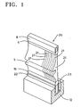
- the reed 20 shown in Figs. 1 and 2 has a plurality of lamellae arranged side by side in a row 21 on.
- the slats 21 are provided with a cutout, so that they enter a guide channel 5 for a To form weft.
- the fins 21 are in their upper and lower end portions by means of connecting spirals 6, 19 in one defined distance from each other and kept in one attached upper profile 8 and a lower profile 22.
- the Slats 21 are both in the connecting spirals 6, 19 as also glued into the upper profile 8 and the lower profile 22.
- the lower profile 22 is by means of a wedge 23 and Screws 11 attached to a loading beam 12.
- the loading bar 12 is parallel in a known manner by means of Laden stilts attached to the loading shaft at the loading shaft of the batten.
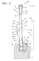
- the fins 21 have a substantially rectangular lower Section 14, which has a width 15 of about 6 mm. This is significantly larger than the width of the usual Slats, which is on the order of only 4 mm.
- the fins 21 further have a substantially rectangular upper section 16, which has a width of the order of magnitude of 4 mm. This corresponds to the width of the conventional Slats in this section.
- the slats 21 also have a central portion 18, the U-shaped is profiled and attached to the lower section 14 and the the upper section 16 connects.
- the middle section 18 has an edge 24 that connects to the back Edge 25 of the lower portion 14 and the back edge 26 of the upper portion 16 represents.
- the middle section 18 is on its front with an upper curved Edge 27 provided in the leading edge 13 of the upper section 16 passes. This curved edge 27 goes via a curve into the upper edge 29 of the cutout, which form the guide channel 5.
- the section 14 with a width of about 6 mm has next the advantages already mentioned, the advantage on that the lamellae 21 in comparison to the conventional Fins in the area between the lower profile 22 and the stop edge 31 are much stronger, so that the danger fractures of the fins 21 in this area lower is.
- the range of the upper section 16 extended by the curved Edge 27 has been shortened. This is the weight of the slats in the area of this section 16 compared to the conventional ones Slats reduced.
- the center of the stop edge 31, with the usual weft threads struck at the edge of the goods, is located in a distance 34 of about 48 mm from the lower end of the slats 21.
- the distance 35 between the lower end and the upper end of the fins 21 is about 104 mm. This Distance can in modified embodiments between about 94 mm and 104 mm.
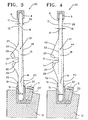
- the fins shown in Figs. 3 and 4 have the same Advantages as the slats of FIG. 2.
- the slat 37 of FIG. 3 has in the upper portion 16 a short straight edge 38, which by means of a relatively long, straight Edge 39 to the also relatively short, straight edge 25 of lower section 14 connects.
- a short straight edge 38 which by means of a relatively long, straight Edge 39 to the also relatively short, straight edge 25 of lower section 14 connects.
- the Thread guide channel 5 is another, curved leading edge provided, which is shorter than the edge 28 of the embodiment is shown in FIG. 2.
- the lamella 41 according to FIG. 4 has above the recess 5 an edge 42 which is longer than the edge 27 of FIG. 2 and is 3 and corresponds approximately to the edges of conventional slats.
- the fins 41 in the section 16 a relatively long, straight edge 26 (similar to FIG. 2) and in the region of the lower portion 14 a relative long, straight edge 43 up. These two are in the field above the guide channel by means of a relatively short, also rectilinear edge 44 connected.
- the weight of the blade 41 above the stop edge 31 slightly larger than in the embodiment according to Fig. 2 or 3, but also the width and thus the strength the fins 41 between the lower profile 22 and the stop edge 31 larger.
- a blade 45 is shown, which is similar to Slat 37 of FIG. 3 is executed, but the back is Edge 46 between the upper end 48 and the lower end 49 of the fins 45 a straight line.
- the edge 46 runs under an angle 47 of about 1.15 ° to a line 52 parallel to the line 33 which passes through the leading edge 23rd of the upper portion 16, the leading edge 32 of the lower portion 14 and the stop edge 31 is placed.
- the blade 50 shown in FIG. 6 is similar to the blade 41 of FIG. 4, but also runs here the back Edge 51 between the upper end 48 and the lower end 49 of the fins 50 rectilinear.
- the fins 45 and 50 In the area of the upper profile the fins 45 and 50 have an approximately rectangular Side surface of about 4 mm and in the area of the lower profile a substantially rectangular section 14 having a width 15 in the order of 6 mm.
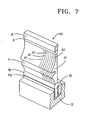
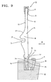
- FIGS. 7 and 8 have the Blades 61 a starting from the upper portion 16 rectilinear rear edge 69. In the area of its front edge they are designed according to the embodiment of FIG. 2, so that reference is made to its description.
- the lower portion 14 is again in two sections Divided 66 and 68, with the upper section 68 from the upper edge 63 of the profile 62 to the section 66 rejuvenated.
- the lower portion 66 has a width 67 of about 4 mm.
- a wedge-shaped portion 68 the lower portion 66 with the protruding from the lower profile Part of Section 14 connects, with the section 14 has a width 15 of about 6 mm.
- the leading edge 65 this section merges into the curved leading edge 28.
- the leading edge of the lowermost portion 66 extends in one Line with the stop edge 31 and the edge 13 of the upper Distance. At this edge has the leading edge of the lower Profiles 62 a distance 70 of about 2 mm. This results a construction in which the width of the profile 62 practically identical to the width of a conventional profile is.
- the lower profile has a width of about 8 mm, so that the same fasteners as in conventional Web leaves can be used, i. the Terminal block 10 and the screws 11, to this on a loading beam 12 to attach.
- the lower portion 14 of the fins 61 has a width. 15 of 6 mm, i. Section 14, taken from the Top edge 63 of the lower profile 62 protrudes, they have Slats 61 have the same advantages already to the embodiments have been described according to FIGS. 2 to 6. It will on the one hand the risk of streaks in the tissue at high weaving speeds reduces, while at the same time the danger the fraction of lamellae is reduced.
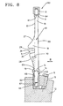
- the fins 71 have a reed 72 substantially the shape of the slats 61 of the embodiment of FIG. 8. They differ However, in the area of the lower section 73, with the they are mounted within a lower profile 76. Of the lower portion 73 of the fins 71 has in the from Top edge 77 of the profile 76 protruding part a width in direction B of about 6 mm. The one within the profile Part of section 73 then tapers to a Width of about 4 mm, with the side edges 74, 75 first have a curvature and steplessly into a substantially rectangular surface, in which they have a width of about 4 mm.
- the side walls of the lower profile 76 have corresponding contours, so that the lower profile 76 only Outside dimensions, which corresponds to the outer dimensions of the lower Have profile of a conventional reed.
- the curved ones Surfaces 74, 75 of the lower portion 73 extend approximately over 1/3 of the height of the lower profile 76.
- Fig. 10 is a reed 80th represented, likewise a multiplicity in a row next to each other arranged slats 81 has.
- These slats have a middle section that deals with a constant width in the direction B of about 6 mm between an upper profile 82 and a lower profile 83 extends.
- the profile 83 has an outer contour, the outer contour of the lower Profile of a conventional reed corresponds, i. has a width of about 8 mm. This makes it possible this reed 80 instead of a conventional reed in the same loading bar 12 by means of the same fastening means 10, 11 to install.
- the fins 81 in the section between the lower edge 88 of the upper profile 82 and the upper edge 89th of the lower profile 83 have an enlarged width, for example, a width of 6 mm, but above all the lower profile 83 but also the upper profile 82 an outer contour which is not larger than the corresponding ones Profiles for conventional reeds, in which the slats a width in direction B of the order of only 4 mm have.
- the invention is also applicable to slats of other shapes than applicable to the illustrated forms. It can also for the Slats and / or for the upper and lower profile combinations the individual embodiments are used. Because it in the area of the upper profile is not an increase in strength arrives, but strives for a weight reduction can, in this area, others and in particular graduated shapes for the inner contour of the upper profile and the upper ends of the slats are provided.
- the slats of the invention and the produced therefrom Web leaves are for use in air jet looms, Rapier looms, water jet looms or with others Liquefied weaving machines, projectile weaving machines, Weft spools and other weaving machine types suitable.
Landscapes
- Engineering & Computer Science (AREA)
- Textile Engineering (AREA)
- Looms (AREA)
Abstract
Description
- Fig. 1
- zeigt eine perspektivische Ansicht eines Ausschnittes eines erfindungsgemäßen, an einem Ladenbalken montierten Webblattes,
- Fig. 2
- einen Schnitt durch das Webblatt der Fig. 1 in größerem Maßstab,
- Fig. 3 bis 6
- Schnitte ähnlich Fig. 2 durch abgewandelte Ausführungsformen,
- Fig. 7
- eine perspektivische Ansicht eines Ausschnittes einer abgewandelten Ausführungsform eines erfindungsgemäßen Webblattes,
- Fig. 8
- einen Querschnitt durch das Webblatt der Fig. 7,
- Fig. 9
- einen Schnitt ähnlich Fig. 8 durch eine abgewandelte Ausführungsform und
- Fig. 10
- einen Schnitt ähnlich Fig. 8 durch eine weitere Ausführungsform eines erfindungsgemäßen Webblattes.
Claims (9)
- Webblatt mit einer Vielzahl von in einer Reihe nebeneinander angeordneten Lamellen (61, 71), deren Enden in einem unteren, an einem Ladenbalken (12) einer Weblade anbringbaren Profil (62, 76) und in einem oberen Profil (8) gehalten sind, dadurch gekennzeichnet, dass die Lamellen (61, 71) in einem aus dem unteren Profil (62, 76) herausragenden Abschnitt (14) eine Breite von etwa 6 mm und in einem oberen Abschnitt (16) eine Breite von etwa 4 mm aufweisen und dass die Lamellen (61, 71) einen in dem unteren Profil (62, 76) befindlichen rechteckigen Abschnitt (66) haben, der mit einem sich keilförmig erweiternden Abschnitt (68, 73) an den eine Breite von etwa 6 mm aufweisenden Abschnitt (14) anschließt.
- Webblatt nach Anspruch 1, dadurch gekennzeichnet, dass die Vorderkanten des unteren Abschnittes (66) und des oberen Abschnittes (16) der Lamellen wenigstens annähernd mit einer im Bereich eines Ausschnittes der Lamellen gebildeten Anschlagkante fluchten.
- Webblatt nach Anspruch 1 oder 2, dadurch gekennzeichnet, dass die Lamellen (61, 71) zum Bilden eines Führungskanals (5) in einem mittleren Abschnitt mit einem im Wesentlichen U-förmigen Ausschnitt versehen sind.
- Webblatt nach einem der Ansprüche 1 bis 3, dadurch gekennzeichnet, dass die Lamellen (61, 71) innerhalb des oberen Profils (8) eine im Wesentlichen rechteckige Form mit einer Breite von etwa 4 mm aufweisen.
- Webblatt nach einem der Ansprüche 1 bis 4, dadurch gekennzeichnet, dass die Lamellen (61, 71) eine dem Führungskanal (5) abgewandte, in dem oberen Profil (8) und dem unteren Profil (62, 76) geradlinig verlaufende Kante aufweisen.
- Webblatt nach einem der Ansprüche 1 bis 5, dadurch gekennzeichnet, dass der eine Breite von etwa 6mm aufweisende Abschnitt (14) den innerhalb des unteren Profils (62, 76) befindlichen rechteckigen Abschnitt bezüglich dessen Vorderkante und dessen Hinterkante überragt.
- Lamelle (61, 71) für eine Webblatt (60, 72) mit einem oberen, in einem oberen Profil (8) anzuordnenden Abschnitt und einem unteren, in einem unteren Profil (62, 76) anzuordnenden Abschnitt, dadurch gekennzeichnet, dass der untere Abschnitt in dem aus dem Profil (62, 76) herausragenden Bereich eine Breite von etwa 6 mm und der obere Abschnitt eine Breite von etwa 4 mm aufweisen, und dass ein in dem unteren Profil (62, 76) anzuordnender recheckiger Abschnitt (66) vorgesehen ist, der mit einem sich keilförmig erweiternden Abschnitt (68, 73) an den eine Breite von etwa 6 mm aufweisenden Abschnitt anschließt.
- Lamelle nach Anspruch 7, dadurch gekennzeichnet, dass die Vorderkanten des unteren Abschnittes (66) und des oberen Abschnittes (16) der Lamelle wenigstens annähernd mit einer im Bereich eines Ausschnitts der Lamelle gebildeten Anschlagkante fluchten.
- Lamelle nach Anspruch 7 oder 8, dadurch gekennzeichnet, dass der etwas 6 mm breite Abschnitt (14) die Vorderkante und die Hinterkante des rechteckigen Abschnitt (64) überragt.
Applications Claiming Priority (8)
| Application Number | Priority Date | Filing Date | Title |
|---|---|---|---|
| BE9800446 | 1998-06-10 | ||
| BE9800446A BE1012031A3 (nl) | 1998-06-10 | 1998-06-10 | Riet voor een luchtweefmachine. |
| BE9800648 | 1998-09-04 | ||
| BE9800648A BE1013010A6 (nl) | 1998-09-04 | 1998-09-04 | Riet voor een luchtweefmachine. |
| BE9800649A BE1012164A3 (nl) | 1998-09-04 | 1998-09-04 | Riet voor een weefmachine. |
| BE9800649 | 1998-09-04 | ||
| EP02028178A EP1318220B1 (de) | 1998-06-10 | 1999-06-09 | Webblatt und Lamelle |
| EP99927931A EP1086267B1 (de) | 1998-06-10 | 1999-06-09 | Webblatt und lamelle |
Related Parent Applications (1)
| Application Number | Title | Priority Date | Filing Date |
|---|---|---|---|
| EP02028178A Division EP1318220B1 (de) | 1998-06-10 | 1999-06-09 | Webblatt und Lamelle |
Publications (3)
| Publication Number | Publication Date |
|---|---|
| EP1500732A2 true EP1500732A2 (de) | 2005-01-26 |
| EP1500732A3 EP1500732A3 (de) | 2005-05-11 |
| EP1500732B1 EP1500732B1 (de) | 2007-08-08 |
Family
ID=27159867
Family Applications (3)
| Application Number | Title | Priority Date | Filing Date |
|---|---|---|---|
| EP99927931A Expired - Lifetime EP1086267B1 (de) | 1998-06-10 | 1999-06-09 | Webblatt und lamelle |
| EP04017564A Expired - Lifetime EP1500732B1 (de) | 1998-06-10 | 1999-06-09 | Webblatt und Lamelle |
| EP02028178A Expired - Lifetime EP1318220B1 (de) | 1998-06-10 | 1999-06-09 | Webblatt und Lamelle |
Family Applications Before (1)
| Application Number | Title | Priority Date | Filing Date |
|---|---|---|---|
| EP99927931A Expired - Lifetime EP1086267B1 (de) | 1998-06-10 | 1999-06-09 | Webblatt und lamelle |
Family Applications After (1)
| Application Number | Title | Priority Date | Filing Date |
|---|---|---|---|
| EP02028178A Expired - Lifetime EP1318220B1 (de) | 1998-06-10 | 1999-06-09 | Webblatt und Lamelle |
Country Status (5)
| Country | Link |
|---|---|
| US (1) | US6401762B1 (de) |
| EP (3) | EP1086267B1 (de) |
| JP (1) | JP4553486B2 (de) |
| DE (3) | DE59914449D1 (de) |
| WO (1) | WO1999064654A1 (de) |
Cited By (1)
| Publication number | Priority date | Publication date | Assignee | Title |
|---|---|---|---|---|
| BE1016547A3 (nl) * | 2005-03-15 | 2007-01-09 | Picanol Nv | Riet voor een weefmachine en weefmachine. |
Families Citing this family (7)
| Publication number | Priority date | Publication date | Assignee | Title |
|---|---|---|---|---|
| JP2004068164A (ja) * | 2002-08-01 | 2004-03-04 | Tsudakoma Corp | 製織用筬 |
| DE102007043111A1 (de) | 2007-08-31 | 2009-03-05 | Picanol N.V. | Rahmen mit Steherlamellen und Führungslamellen |
| DE102007043112A1 (de) | 2007-08-31 | 2009-03-05 | Picanol N.V. | Verfahren zum Verbinden einer Vielzahl von Lamellen und Vorrichtung aus einer Vielzahl von Lamellen |
| RU2348746C1 (ru) * | 2007-09-26 | 2009-03-10 | Алексей Николаевич Конов | Бердо ткацкого станка |
| CN102747516A (zh) * | 2012-07-11 | 2012-10-24 | 江苏万工科技集团有限公司 | 异形钢筘防震装置 |
| WO2018007874A1 (en) * | 2016-07-04 | 2018-01-11 | Kurkute Sanjay | Easy and effective reed clamping arrangement for weaving machines |
| KR102118330B1 (ko) * | 2019-01-23 | 2020-06-03 | 삼성에스티에스(주) | 직조기 리드 및 직조기 리드의 제조 방법 |
Family Cites Families (15)
| Publication number | Priority date | Publication date | Assignee | Title |
|---|---|---|---|---|
| GB559430A (en) * | 1942-08-18 | 1944-02-18 | James Nelson Ltd | A method of securely holding loom reeds |
| US2383140A (en) * | 1945-03-26 | 1945-08-21 | Southern Loom Reed Mfg Company | Loom reed |
| CH467369A (de) * | 1967-11-16 | 1969-01-15 | Charles Arnold William | Verfahren zur Herstellung eines Weberkammes, nach dem Verfahren hergestellter Weberkamm und Verwendung des nach dem Verfahren hergestellten Weberkammes |
| US3818952A (en) * | 1969-08-07 | 1974-06-25 | G Vermeulen | Jet operated weaving machine |
| NL7204904A (en) * | 1972-04-12 | 1973-10-16 | Terry pile type weaving - with a fixed reed | |
| DE8130278U1 (de) * | 1980-11-20 | 1982-03-11 | Gebrüder Sulzer AG, 8401 Winterthur | "riet fuer eine webmaschine" |
| CH649586A5 (de) * | 1981-03-05 | 1985-05-31 | Rueti Ag Maschf | Blattzahn fuer duesenwebmaschinen und unter verwendung des blattzahns hergestelltes webblatt. |
| US4529014A (en) * | 1983-08-29 | 1985-07-16 | Steel Heddle Mfg., Co. | Loom reed with plastic profiled dents |
| JP2660556B2 (ja) * | 1988-08-16 | 1997-10-08 | 日産テクシス株式会社 | 空気噴射式織機の緯入れ装置 |
| JPH02169746A (ja) * | 1988-12-20 | 1990-06-29 | Asahi Chem Ind Co Ltd | シックアンドシン糸のエアージェットルームによる製織方法 |
| FR2688520B1 (fr) * | 1992-03-12 | 1994-05-27 | Burckle Cie Sa Ets | Peigne pour machine a tisser a jet d'air et son procede de fabrication. |
| IT1266634B1 (it) * | 1993-10-27 | 1997-01-09 | Nuovo Pignone Spa | Pettine perfezionato per telaio tessile ad aria |
| BE1010333A3 (nl) * | 1996-06-07 | 1998-06-02 | Picanol Nv | Riet voor een luchtweefmachine. |
| US6019139A (en) * | 1998-09-30 | 2000-02-01 | Stell Heddle Mfg. Co. | Weaving reed having reinforced dents |
| JP4172089B2 (ja) * | 1999-05-17 | 2008-10-29 | 東レ株式会社 | ノンコートエアバッグ用基布およびその製造方法 |
-
1999
- 1999-06-09 DE DE59914449T patent/DE59914449D1/de not_active Expired - Lifetime
- 1999-06-09 EP EP99927931A patent/EP1086267B1/de not_active Expired - Lifetime
- 1999-06-09 EP EP04017564A patent/EP1500732B1/de not_active Expired - Lifetime
- 1999-06-09 DE DE59910957T patent/DE59910957D1/de not_active Expired - Lifetime
- 1999-06-09 WO PCT/EP1999/003976 patent/WO1999064654A1/de not_active Ceased
- 1999-06-09 JP JP2000553642A patent/JP4553486B2/ja not_active Expired - Lifetime
- 1999-06-09 US US09/701,578 patent/US6401762B1/en not_active Expired - Lifetime
- 1999-06-09 EP EP02028178A patent/EP1318220B1/de not_active Expired - Lifetime
- 1999-06-09 DE DE59907557T patent/DE59907557D1/de not_active Expired - Lifetime
Cited By (1)
| Publication number | Priority date | Publication date | Assignee | Title |
|---|---|---|---|---|
| BE1016547A3 (nl) * | 2005-03-15 | 2007-01-09 | Picanol Nv | Riet voor een weefmachine en weefmachine. |
Also Published As
| Publication number | Publication date |
|---|---|
| WO1999064654A1 (de) | 1999-12-16 |
| EP1086267B1 (de) | 2003-10-29 |
| DE59907557D1 (de) | 2003-12-04 |
| EP1500732A3 (de) | 2005-05-11 |
| JP2002517633A (ja) | 2002-06-18 |
| EP1318220B1 (de) | 2004-10-27 |
| EP1318220A1 (de) | 2003-06-11 |
| DE59914449D1 (de) | 2007-09-20 |
| US6401762B1 (en) | 2002-06-11 |
| JP4553486B2 (ja) | 2010-09-29 |
| EP1500732B1 (de) | 2007-08-08 |
| DE59910957D1 (de) | 2004-12-02 |
| EP1086267A1 (de) | 2001-03-28 |
Similar Documents
| Publication | Publication Date | Title |
|---|---|---|
| EP0021128B1 (de) | Webblatt für eine Düsenwebmaschine | |
| EP0523313A1 (de) | Siebelement | |
| DE2642734B2 (de) | Lamellenkamm einer Düsenwebmaschine | |
| DE4336362C1 (de) | Fadenauge für Weblitze | |
| DE69502544T2 (de) | Schussfadeneintragsvorrichtung in eine Luftdüsenwebmaschine | |
| EP1500732B1 (de) | Webblatt und Lamelle | |
| EP1514961B1 (de) | Litze mit vermindertem Spiel | |
| DE3444973C1 (de) | Weblade mit Webblatt fuer Duesenwebmaschinen | |
| DE2905221C2 (de) | Blaswerk für schützenlose Webmaschinen | |
| DE9108129U1 (de) | Siebelement | |
| WO2000063473A1 (de) | Hilfsdüse für eine webmaschine | |
| EP0822998B1 (de) | Webmaschine | |
| DE19800811B4 (de) | Weblitze | |
| DE3214535A1 (de) | Webblatt fuer duesenwebmaschinen | |
| DE3207481A1 (de) | Blattzahn fuer duesenwebmaschinen und unter verwendung des blattzahns hergestelltes webblatt | |
| DE3642712C2 (de) | ||
| DE102004049254B4 (de) | Greifertransportelement für eine Webmaschine | |
| EP1664411B1 (de) | FüHRUNGSELEMENT FüR EIN GREIFERBAND | |
| EP3438335A1 (de) | Riet und rundwebmaschine | |
| DE1267960B (de) | Papiermaschinensieb | |
| DE2449974A1 (de) | Webeblatt oder riet | |
| DE2456549C3 (de) | Wellenwebmaschine | |
| DE102004049255A1 (de) | Führungselemente für ein Greifertransportelement einer Webmaschine | |
| DE19515475A1 (de) | Webblatt für eine Webmaschine | |
| DE2919026A1 (de) | Vorrichtung zum schusseintrag an webmaschinen mittels eines stroemenden mediums |
Legal Events
| Date | Code | Title | Description |
|---|---|---|---|
| PUAI | Public reference made under article 153(3) epc to a published international application that has entered the european phase |
Free format text: ORIGINAL CODE: 0009012 |
|
| AC | Divisional application: reference to earlier application |
Ref document number: 1318220 Country of ref document: EP Kind code of ref document: P Ref document number: 1086267 Country of ref document: EP Kind code of ref document: P |
|
| AK | Designated contracting states |
Kind code of ref document: A2 Designated state(s): BE CH DE FR GB IT LI |
|
| PUAL | Search report despatched |
Free format text: ORIGINAL CODE: 0009013 |
|
| AK | Designated contracting states |
Kind code of ref document: A3 Designated state(s): BE CH DE FR GB IT LI |
|
| 17P | Request for examination filed |
Effective date: 20050610 |
|
| AKX | Designation fees paid |
Designated state(s): BE CH DE FR GB IT LI |
|
| GRAP | Despatch of communication of intention to grant a patent |
Free format text: ORIGINAL CODE: EPIDOSNIGR1 |
|
| GRAS | Grant fee paid |
Free format text: ORIGINAL CODE: EPIDOSNIGR3 |
|
| GRAA | (expected) grant |
Free format text: ORIGINAL CODE: 0009210 |
|
| AC | Divisional application: reference to earlier application |
Ref document number: 1086267 Country of ref document: EP Kind code of ref document: P Ref document number: 1318220 Country of ref document: EP Kind code of ref document: P |
|
| AK | Designated contracting states |
Kind code of ref document: B1 Designated state(s): BE CH DE FR GB IT LI |
|
| REG | Reference to a national code |
Ref country code: GB Ref legal event code: FG4D Free format text: NOT ENGLISH |
|
| GBT | Gb: translation of ep patent filed (gb section 77(6)(a)/1977) |
Effective date: 20070808 |
|
| REG | Reference to a national code |
Ref country code: CH Ref legal event code: EP |
|
| REF | Corresponds to: |
Ref document number: 59914449 Country of ref document: DE Date of ref document: 20070920 Kind code of ref document: P |
|
| REG | Reference to a national code |
Ref country code: CH Ref legal event code: NV Representative=s name: ZIMMERLI, WAGNER & PARTNER AG |
|
| ET | Fr: translation filed | ||
| PLBE | No opposition filed within time limit |
Free format text: ORIGINAL CODE: 0009261 |
|
| STAA | Information on the status of an ep patent application or granted ep patent |
Free format text: STATUS: NO OPPOSITION FILED WITHIN TIME LIMIT |
|
| 26N | No opposition filed |
Effective date: 20080509 |
|
| REG | Reference to a national code |
Ref country code: CH Ref legal event code: PFA Owner name: PICANOL N.V. Free format text: PICANOL N.V.#TER WAARDE 50#8900 IEPER (BE) -TRANSFER TO- PICANOL N.V.#TER WAARDE 50#8900 IEPER (BE) |
|
| PGFP | Annual fee paid to national office [announced via postgrant information from national office to epo] |
Ref country code: GB Payment date: 20090623 Year of fee payment: 11 |
|
| GBPC | Gb: european patent ceased through non-payment of renewal fee |
Effective date: 20100609 |
|
| PG25 | Lapsed in a contracting state [announced via postgrant information from national office to epo] |
Ref country code: GB Free format text: LAPSE BECAUSE OF NON-PAYMENT OF DUE FEES Effective date: 20100609 |
|
| PGFP | Annual fee paid to national office [announced via postgrant information from national office to epo] |
Ref country code: CH Payment date: 20120622 Year of fee payment: 14 |
|
| REG | Reference to a national code |
Ref country code: DE Ref legal event code: R082 Ref document number: 59914449 Country of ref document: DE Representative=s name: PATENTANWAELTE RUFF, WILHELM, BEIER, DAUSTER &, DE |
|
| REG | Reference to a national code |
Ref country code: DE Ref legal event code: R082 Ref document number: 59914449 Country of ref document: DE Representative=s name: PATENTANWAELTE RUFF, WILHELM, BEIER, DAUSTER &, DE Effective date: 20120814 Ref country code: DE Ref legal event code: R081 Ref document number: 59914449 Country of ref document: DE Owner name: PICANOL, BE Free format text: FORMER OWNER: PICANOL N.V., IEPER, BE Effective date: 20120814 |
|
| REG | Reference to a national code |
Ref country code: CH Ref legal event code: PL |
|
| PG25 | Lapsed in a contracting state [announced via postgrant information from national office to epo] |
Ref country code: LI Free format text: LAPSE BECAUSE OF NON-PAYMENT OF DUE FEES Effective date: 20130630 Ref country code: CH Free format text: LAPSE BECAUSE OF NON-PAYMENT OF DUE FEES Effective date: 20130630 |
|
| REG | Reference to a national code |
Ref country code: FR Ref legal event code: PLFP Year of fee payment: 17 |
|
| PGFP | Annual fee paid to national office [announced via postgrant information from national office to epo] |
Ref country code: DE Payment date: 20150630 Year of fee payment: 17 |
|
| PGFP | Annual fee paid to national office [announced via postgrant information from national office to epo] |
Ref country code: BE Payment date: 20150519 Year of fee payment: 17 Ref country code: FR Payment date: 20150623 Year of fee payment: 17 |
|
| PGFP | Annual fee paid to national office [announced via postgrant information from national office to epo] |
Ref country code: IT Payment date: 20150625 Year of fee payment: 17 |
|
| PG25 | Lapsed in a contracting state [announced via postgrant information from national office to epo] |
Ref country code: BE Free format text: LAPSE BECAUSE OF NON-PAYMENT OF DUE FEES Effective date: 20160630 |
|
| REG | Reference to a national code |
Ref country code: DE Ref legal event code: R119 Ref document number: 59914449 Country of ref document: DE |
|
| REG | Reference to a national code |
Ref country code: FR Ref legal event code: ST Effective date: 20170228 |
|
| PG25 | Lapsed in a contracting state [announced via postgrant information from national office to epo] |
Ref country code: DE Free format text: LAPSE BECAUSE OF NON-PAYMENT OF DUE FEES Effective date: 20170103 Ref country code: FR Free format text: LAPSE BECAUSE OF NON-PAYMENT OF DUE FEES Effective date: 20160630 |
|
| PG25 | Lapsed in a contracting state [announced via postgrant information from national office to epo] |
Ref country code: IT Free format text: LAPSE BECAUSE OF NON-PAYMENT OF DUE FEES Effective date: 20160609 |