EP1500732A2 - Weaving reed and lamella - Google Patents
Weaving reed and lamella Download PDFInfo
- Publication number
- EP1500732A2 EP1500732A2 EP04017564A EP04017564A EP1500732A2 EP 1500732 A2 EP1500732 A2 EP 1500732A2 EP 04017564 A EP04017564 A EP 04017564A EP 04017564 A EP04017564 A EP 04017564A EP 1500732 A2 EP1500732 A2 EP 1500732A2
- Authority
- EP
- European Patent Office
- Prior art keywords
- profile
- width
- section
- edge
- reed
- Prior art date
- Legal status (The legal status is an assumption and is not a legal conclusion. Google has not performed a legal analysis and makes no representation as to the accuracy of the status listed.)
- Granted
Links
Images


Classifications
-
- D—TEXTILES; PAPER
- D03—WEAVING
- D03D—WOVEN FABRICS; METHODS OF WEAVING; LOOMS
- D03D47/00—Looms in which bulk supply of weft does not pass through shed, e.g. shuttleless looms, gripper shuttle looms, dummy shuttle looms
- D03D47/27—Drive or guide mechanisms for weft inserting
- D03D47/277—Guide mechanisms
- D03D47/278—Guide mechanisms for pneumatic looms
-
- D—TEXTILES; PAPER
- D03—WEAVING
- D03D—WOVEN FABRICS; METHODS OF WEAVING; LOOMS
- D03D49/00—Details or constructional features not specially adapted for looms of a particular type
- D03D49/60—Construction or operation of slay
- D03D49/62—Reeds mounted on slay
Definitions
- the invention relates to a reed with a variety of in a series of slats arranged side by side, their ends in a lower, to be mounted in a loading beam of a batten Profile and are held in an upper profile.
- slats are provided, between the lower and upper sections still have a section with a U-shaped cutout, by which a guide channel for the weft thread is formed becomes.
- the invention is based on the object, a reed of to create the type mentioned above, for high weaving speeds suitable is.
- This object is achieved in that the slats at least in a section protruding from the lower profile a width of about 6 mm and in an upper section have a width of about 4 mm.
- the invention is based on the recognition that the cause for the stripes occurring at high web speeds in the tissue in the reeds, which then dynamic Vibrations of the slats arise.
- the fins in the lower section are the fins relatively stiff, so that the deflection, in particular during Striking a weft is reduced and thus also the resulting vibrations of the slats.
- the vibrations of the slats are thus due to their relatively stiff lower Section and their relatively light upper section limited.
- leading edges the lower section and the upper section of the lamellae at least approximately in the region of Clipping stop edge formed align. This will achieved that the reed formed with these blades alternatively be used to a conventional reed can, without making any significant changes to a loom necessary.
- the slats facing away from the guide channel, between the upper and lower profile substantially rectilinear Edge have. This has the advantage that the slats placed during assembly of a reed with this edge can be.
- the lamellae in the section with which they are in the lower or upper profile protrude, one wedge-shaped decreasing width, wherein the cross section of the lower and / or upper profile of this wedge-shaped shape is adapted.
- This embodiment of the invention has the advantage that in particular the outer contour of the lower profile not be changed compared to conventional reeds must, so that it is readily possible, as an alternative to conventional Web leaves to a reed according to the invention use without making any further changes to the loom to have to. With the help of this configuration can be also reeds with relatively wide slats with straight lines Leading edge and back edge form for high weaving Web speeds and / or weaving heavy fabrics are recommended.
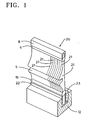
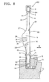
- the reed 20 shown in Figs. 1 and 2 has a plurality of lamellae arranged side by side in a row 21 on.
- the slats 21 are provided with a cutout, so that they enter a guide channel 5 for a To form weft.
- the fins 21 are in their upper and lower end portions by means of connecting spirals 6, 19 in one defined distance from each other and kept in one attached upper profile 8 and a lower profile 22.
- the Slats 21 are both in the connecting spirals 6, 19 as also glued into the upper profile 8 and the lower profile 22.
- the lower profile 22 is by means of a wedge 23 and Screws 11 attached to a loading beam 12.
- the loading bar 12 is parallel in a known manner by means of Laden stilts attached to the loading shaft at the loading shaft of the batten.
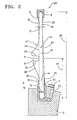
- the fins 21 have a substantially rectangular lower Section 14, which has a width 15 of about 6 mm. This is significantly larger than the width of the usual Slats, which is on the order of only 4 mm.
- the fins 21 further have a substantially rectangular upper section 16, which has a width of the order of magnitude of 4 mm. This corresponds to the width of the conventional Slats in this section.
- the slats 21 also have a central portion 18, the U-shaped is profiled and attached to the lower section 14 and the the upper section 16 connects.
- the middle section 18 has an edge 24 that connects to the back Edge 25 of the lower portion 14 and the back edge 26 of the upper portion 16 represents.
- the middle section 18 is on its front with an upper curved Edge 27 provided in the leading edge 13 of the upper section 16 passes. This curved edge 27 goes via a curve into the upper edge 29 of the cutout, which form the guide channel 5.
- the section 14 with a width of about 6 mm has next the advantages already mentioned, the advantage on that the lamellae 21 in comparison to the conventional Fins in the area between the lower profile 22 and the stop edge 31 are much stronger, so that the danger fractures of the fins 21 in this area lower is.
- the range of the upper section 16 extended by the curved Edge 27 has been shortened. This is the weight of the slats in the area of this section 16 compared to the conventional ones Slats reduced.
- the center of the stop edge 31, with the usual weft threads struck at the edge of the goods, is located in a distance 34 of about 48 mm from the lower end of the slats 21.
- the distance 35 between the lower end and the upper end of the fins 21 is about 104 mm. This Distance can in modified embodiments between about 94 mm and 104 mm.
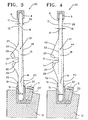
- the fins shown in Figs. 3 and 4 have the same Advantages as the slats of FIG. 2.
- the slat 37 of FIG. 3 has in the upper portion 16 a short straight edge 38, which by means of a relatively long, straight Edge 39 to the also relatively short, straight edge 25 of lower section 14 connects.
- a short straight edge 38 which by means of a relatively long, straight Edge 39 to the also relatively short, straight edge 25 of lower section 14 connects.
- the Thread guide channel 5 is another, curved leading edge provided, which is shorter than the edge 28 of the embodiment is shown in FIG. 2.
- the lamella 41 according to FIG. 4 has above the recess 5 an edge 42 which is longer than the edge 27 of FIG. 2 and is 3 and corresponds approximately to the edges of conventional slats.
- the fins 41 in the section 16 a relatively long, straight edge 26 (similar to FIG. 2) and in the region of the lower portion 14 a relative long, straight edge 43 up. These two are in the field above the guide channel by means of a relatively short, also rectilinear edge 44 connected.
- the weight of the blade 41 above the stop edge 31 slightly larger than in the embodiment according to Fig. 2 or 3, but also the width and thus the strength the fins 41 between the lower profile 22 and the stop edge 31 larger.
- a blade 45 is shown, which is similar to Slat 37 of FIG. 3 is executed, but the back is Edge 46 between the upper end 48 and the lower end 49 of the fins 45 a straight line.
- the edge 46 runs under an angle 47 of about 1.15 ° to a line 52 parallel to the line 33 which passes through the leading edge 23rd of the upper portion 16, the leading edge 32 of the lower portion 14 and the stop edge 31 is placed.
- the blade 50 shown in FIG. 6 is similar to the blade 41 of FIG. 4, but also runs here the back Edge 51 between the upper end 48 and the lower end 49 of the fins 50 rectilinear.
- the fins 45 and 50 In the area of the upper profile the fins 45 and 50 have an approximately rectangular Side surface of about 4 mm and in the area of the lower profile a substantially rectangular section 14 having a width 15 in the order of 6 mm.
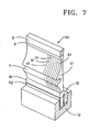
- FIGS. 7 and 8 have the Blades 61 a starting from the upper portion 16 rectilinear rear edge 69. In the area of its front edge they are designed according to the embodiment of FIG. 2, so that reference is made to its description.
- the lower portion 14 is again in two sections Divided 66 and 68, with the upper section 68 from the upper edge 63 of the profile 62 to the section 66 rejuvenated.
- the lower portion 66 has a width 67 of about 4 mm.
- a wedge-shaped portion 68 the lower portion 66 with the protruding from the lower profile Part of Section 14 connects, with the section 14 has a width 15 of about 6 mm.
- the leading edge 65 this section merges into the curved leading edge 28.
- the leading edge of the lowermost portion 66 extends in one Line with the stop edge 31 and the edge 13 of the upper Distance. At this edge has the leading edge of the lower Profiles 62 a distance 70 of about 2 mm. This results a construction in which the width of the profile 62 practically identical to the width of a conventional profile is.
- the lower profile has a width of about 8 mm, so that the same fasteners as in conventional Web leaves can be used, i. the Terminal block 10 and the screws 11, to this on a loading beam 12 to attach.
- the lower portion 14 of the fins 61 has a width. 15 of 6 mm, i. Section 14, taken from the Top edge 63 of the lower profile 62 protrudes, they have Slats 61 have the same advantages already to the embodiments have been described according to FIGS. 2 to 6. It will on the one hand the risk of streaks in the tissue at high weaving speeds reduces, while at the same time the danger the fraction of lamellae is reduced.
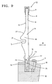
- the fins 71 have a reed 72 substantially the shape of the slats 61 of the embodiment of FIG. 8. They differ However, in the area of the lower section 73, with the they are mounted within a lower profile 76. Of the lower portion 73 of the fins 71 has in the from Top edge 77 of the profile 76 protruding part a width in direction B of about 6 mm. The one within the profile Part of section 73 then tapers to a Width of about 4 mm, with the side edges 74, 75 first have a curvature and steplessly into a substantially rectangular surface, in which they have a width of about 4 mm.
- the side walls of the lower profile 76 have corresponding contours, so that the lower profile 76 only Outside dimensions, which corresponds to the outer dimensions of the lower Have profile of a conventional reed.
- the curved ones Surfaces 74, 75 of the lower portion 73 extend approximately over 1/3 of the height of the lower profile 76.
- Fig. 10 is a reed 80th represented, likewise a multiplicity in a row next to each other arranged slats 81 has.
- These slats have a middle section that deals with a constant width in the direction B of about 6 mm between an upper profile 82 and a lower profile 83 extends.
- the profile 83 has an outer contour, the outer contour of the lower Profile of a conventional reed corresponds, i. has a width of about 8 mm. This makes it possible this reed 80 instead of a conventional reed in the same loading bar 12 by means of the same fastening means 10, 11 to install.
- the fins 81 in the section between the lower edge 88 of the upper profile 82 and the upper edge 89th of the lower profile 83 have an enlarged width, for example, a width of 6 mm, but above all the lower profile 83 but also the upper profile 82 an outer contour which is not larger than the corresponding ones Profiles for conventional reeds, in which the slats a width in direction B of the order of only 4 mm have.
- the invention is also applicable to slats of other shapes than applicable to the illustrated forms. It can also for the Slats and / or for the upper and lower profile combinations the individual embodiments are used. Because it in the area of the upper profile is not an increase in strength arrives, but strives for a weight reduction can, in this area, others and in particular graduated shapes for the inner contour of the upper profile and the upper ends of the slats are provided.
- the slats of the invention and the produced therefrom Web leaves are for use in air jet looms, Rapier looms, water jet looms or with others Liquefied weaving machines, projectile weaving machines, Weft spools and other weaving machine types suitable.
Abstract
Description
Die Erfindung betrifft ein Webblatt mit einer Vielzahl von in einer Reihe nebeneinander angeordneten Lamellen, deren Enden in einem unteren, in einem Ladenbalken einer Weblade anzubringenden Profil und in einem oberen Profil gehalten sind.The invention relates to a reed with a variety of in a series of slats arranged side by side, their ends in a lower, to be mounted in a loading beam of a batten Profile and are held in an upper profile.
Bei Webblättern der eingangs genannten Art, wenn sie für Luftdüsenwebmaschinen eingesetzt werden, werden Lamellen vorgesehen, die zwischen dem unteren und dem oberen Abschnitt noch einen Abschnitt mit einem U-förmigen Ausschnitt aufweisen, durch welchen ein Führungskanal für den Schußfaden gebildet wird.For reeds of the type mentioned, if they are for Air jet looms are used, slats are provided, between the lower and upper sections still have a section with a U-shaped cutout, by which a guide channel for the weft thread is formed becomes.
In der Praxis hat sich gezeigt, daß bei hohen Webgeschwindigkeiten, d.h. bei Webgeschwindigkeiten in der Größenordnung von 1.000 Schuß pro Minute oder mehr, Streifen in dem Gewebe auftreten, so daß sich ein unregelmäßiges Gewebe ergibt.In practice it has been found that at high weaving speeds, i.e. at web speeds of the order of magnitude of 1,000 rounds per minute or more, streaks in the fabric occur, so that results in an irregular tissue.
Der Erfindung liegt die Aufgabe zugrunde, ein Webblatt der eingangs genannten Art zu schaffen, das für hohe Webgeschwindigkeiten geeignet ist.The invention is based on the object, a reed of to create the type mentioned above, for high weaving speeds suitable is.
Diese Aufgabe wird dadurch gelöst, daß die Lamellen wenigstens in einem aus dem unteren Profil herausragenden Abschnitt eine Breite von etwa 6 mm und in einem oberen Abschnitt eine Breite von etwa 4 mm aufweisen.This object is achieved in that the slats at least in a section protruding from the lower profile a width of about 6 mm and in an upper section have a width of about 4 mm.
Die Erfindung geht von der Erkenntnis aus, daß die Ursache für die bei hohen Webgeschwindigkeiten auftretenden Streifen im Gewebe in den Webblättern liegt, bei welchen dann dynamische Schwingungen der Lamellen entstehen. Durch die Verbreiterung der Lamellen in dem unteren Abschnitt sind die Lamellen relativ steif, so daß die Durchbiegung, insbesondere beim Anschlagen eines Schußfadens verringert wird und damit auch die daraus resultierenden Schwingungen der Lamellen. Der obere, relativ schmale Abschnitt, der weiter von der Drehachse der Weblade entfernt ist, besitzt dagegen ein geringes Gewicht, wodurch die auf diesen Abschnitt der Lamellen einwirkenden Trägheitskräft aufgrund der Hin- und Herbewegung der Weblade und die davon abhängigen Durchbiegungen und Schwingungen entsprechend gering bleiben. Die Schwingungen der Lamellen werden somit aufgrund ihres relativ steifen unteren Abschnittes und ihres relativ leichten oberen Abschnittes beschränkt.The invention is based on the recognition that the cause for the stripes occurring at high web speeds in the tissue in the reeds, which then dynamic Vibrations of the slats arise. By the broadening the fins in the lower section are the fins relatively stiff, so that the deflection, in particular during Striking a weft is reduced and thus also the resulting vibrations of the slats. The upper, relatively narrow section, farther from the axis of rotation the batten is removed, however, has a low weight, whereby the forces acting on this section of the slats Inertia due to the float's movement Batten and the dependent deflections and vibrations stay low accordingly. The vibrations of the slats are thus due to their relatively stiff lower Section and their relatively light upper section limited.
In Ausgestaltung der Erfindung wird vorgesehen, daß die Vorderkanten des unteren Abschnittes und des oberen Abschnittes der Lamellen wenigstens annähernd mit einer im Bereich des Ausschnitts gebildeten Anschlagkante fluchten. Dadurch wird erreicht, daß das mit diesen Lamellen gebildete Webblatt alternativ zu einem herkömmlichen Webblatt verwendet werden kann, ohne daß wesentliche Änderungen an einer Webmaschine notwendig sind.In an embodiment of the invention it is provided that the leading edges the lower section and the upper section of the lamellae at least approximately in the region of Clipping stop edge formed align. This will achieved that the reed formed with these blades alternatively be used to a conventional reed can, without making any significant changes to a loom necessary.
In weiterer Ausgestaltung der Erfindung wird vorgesehen, daß die Lamellen eine dem Führungskanal abgewandte, zwischen dem oberen und dem unteren Profil im wesentlichen geradlinig verlaufende Kante aufweisen. Dies hat den Vorteil, daß die Lamellen bei der Montage eines Webblattes mit dieser Kante aufgelegt werden können. In a further embodiment of the invention, it is provided that the slats facing away from the guide channel, between the upper and lower profile substantially rectilinear Edge have. This has the advantage that the slats placed during assembly of a reed with this edge can be.
Bei einer weiteren Ausgestaltung der Erfindung wird vorgesehen, daß die Lamellen in dem Abschnitt, mit welchem sie in das untere oder obere Profil hineinragen, eine sich keilförmig verringernde Breite aufweisen, wobei der Querschnitt des unteren und/oder oberen Profils dieser keilförmigen Gestalt angepaßt ist. Diese Ausgestaltung der Erfindung hat den Vorteil, daß insbesondere die Außenkontur des unteren Profils gegenüber herkömmlichen Webblättern nicht verändert werden muß, so daß es ohne weiteres möglich ist, alternativ zu konventionellen Webblättern ein erfindungsgemäßes Webblatt zu verwenden, ohne weitere Änderungen an der Webmaschine vornehmen zu müssen. Mit Hilfe dieser Ausgestaltung lassen sich auch Webblätter mit relativ breiten Lamellen mit geradliniger Vorderkante und Rückkante bilden, die zum Weben mit hohen Webgeschwindigkeiten und/oder zum Weben von schweren Geweben empfehlenswert sind. Auch in diesem Fall können diese breiten Lamellen verwendet werden, ohne daß die Breite des unteren Profils wesentlich geändert werden muß. Insbesondere können auch die gleichen Befestigungsmittel verwendet werden, mit denen Webblätter mit unterschiedlich breiten Lamellen an dem gleichen Ladenbalken einer Weblade angebracht werden können.In a further embodiment of the invention, it is provided that the lamellae in the section with which they are in the lower or upper profile protrude, one wedge-shaped decreasing width, wherein the cross section of the lower and / or upper profile of this wedge-shaped shape is adapted. This embodiment of the invention has the advantage that in particular the outer contour of the lower profile not be changed compared to conventional reeds must, so that it is readily possible, as an alternative to conventional Web leaves to a reed according to the invention use without making any further changes to the loom to have to. With the help of this configuration can be also reeds with relatively wide slats with straight lines Leading edge and back edge form for high weaving Web speeds and / or weaving heavy fabrics are recommended. Also in this case, these can be broad Slats can be used without changing the width of the lower Profile must be changed significantly. In particular, you can Also the same fasteners can be used with which reeds with different width slats on the same loading bar a batten can be attached.
Weitere Merkmale und Vorteile der Erfindung ergeben sich aus der nachfolgenden Beschreibung der in der Zeichnung dargestellten Ausführungsbeispiele.
- Fig. 1
- zeigt eine perspektivische Ansicht eines Ausschnittes eines erfindungsgemäßen, an einem Ladenbalken montierten Webblattes,
- Fig. 2
- einen Schnitt durch das Webblatt der Fig. 1 in größerem Maßstab,
- Fig. 3 bis 6
- Schnitte ähnlich Fig. 2 durch abgewandelte Ausführungsformen,
- Fig. 7
- eine perspektivische Ansicht eines Ausschnittes einer abgewandelten Ausführungsform eines erfindungsgemäßen Webblattes,
- Fig. 8
- einen Querschnitt durch das Webblatt der Fig. 7,
- Fig. 9
- einen Schnitt ähnlich Fig. 8 durch eine abgewandelte Ausführungsform und
- Fig. 10
- einen Schnitt ähnlich Fig. 8 durch eine weitere Ausführungsform eines erfindungsgemäßen Webblattes.
- Fig. 1
- shows a perspective view of a section of an inventive, mounted on a loading beam reed,
- Fig. 2
- a section through the reed of Figure 1 on a larger scale,
- Fig. 3 to 6
- Sections similar to FIG. 2 by modified embodiments,
- Fig. 7
- a perspective view of a section of a modified embodiment of a reed according to the invention,
- Fig. 8
- a cross section through the reed of Fig. 7,
- Fig. 9
- a section similar to FIG. 8 by a modified embodiment and
- Fig. 10
- a section similar to FIG. 8 by a further embodiment of a reed according to the invention.
Das in Fig. 1 und 2 dargestellte Webblatt 20 weist eine Vielzahl
von in einer Reihe nebeneinander angeordneten Lamellen
21 auf. Die Lamellen 21 sind mit einem Ausschnitt versehen,
so daß sie einen Führungskanal 5 für einen einzutragenden
Schußfaden bilden. Die Lamellen 21 sind in ihren oberen und
unteren Endbereichen mittels Verbindungsspiralen 6, 19 in einem
definierten Abstand voneinander gehalten und in einem
oberen Profil 8 und einem unteren Profil 22 befestigt. Die
Lamellen 21 sind sowohl in die Verbindungsspiralen 6, 19 als
auch in das obere Profil 8 und das untere Profil 22 eingeklebt.
Das untere Profil 22 wird mittels eines Keils 23 und
Schrauben 11 an einem Ladenbalken 12 befestigt. Der Ladenbalken
12 ist in bekannter Weise mittels Ladenstelzen parallel
zur Ladenwelle an der Ladenwelle der Weblade befestigt.The
Die Lamellen 21 weisen einen im wesentlichen rechteckigen unteren
Abschnitt 14 auf, der eine Breite 15 von etwa 6 mm aufweist.
Dies ist deutlich größer als die Breite der üblichen
Lamellen, die in der Größenordnung von nur 4 mm liegt.The
Die Lamellen 21 weisen weiter einen im wesentlichen rechtekkigen
oberen Abschnitt 16 auf, der eine Breite in der Größenordnung
von 4 mm besitzt. Dies entspricht der Breite der konventionellen
Lamellen in diesem Abschnitt. Die Lamellen 21
besitzen ferner einen mittleren Abschnitt 18, der U-förmig
profiliert ist und der an den unteren Abschnitt 14 und den
oberen Abschnitt 16 anschließt. Der mittlere Abschnitt 18
weist eine Kante 24 auf, die eine Verbindung zur rückseitigen
Kante 25 des unteren Abschnittes 14 und der rückseitigen Kante
26 des oberen Abschnittes 16 darstellt. Der mittlere Abschnitt
18 ist auf seiner Vorderseite mit einer oberen gekrümmten
Kante 27 versehen, die in die Vorderkante 13 des
oberen Abschnittes 16 übergeht. Diese gekrümmte Kante 27 geht
über eine Rundung in die Oberkante 29 des Ausschnittes über,
die den Führungskanal 5 bilden. In ähnlicher Weise schließt
an die Vorderkante 32 des unteren Abschnittes 14 eine gekrümmte
Kante 28 an, die mit einer Rundung in die Unterkante
30 der den Führungskanal 5 bildenden Ausschnitte übergeht.
Die Lamellen 21 bilden im Bereich des Führungskanals 5 eine
Anschlagkante 31, die mit der Vorderkante 13 des oberen Abschnittes
16 und der Vorderkante 32 des unteren Abschnittes
14 in einer Linie 33 liegt.The
Der Abschnitt 14 mit einer Breite von etwa 6 mm weist neben
den bereits eingangs genannten Vorteilen noch den Vorteil
auf, daß die Lamellen 21 im Vergleich zu den konventionellen
Lamellen in dem Bereich zwischen dem unteren Profil 22 und
der Anschlagkante 31 wesentlich stärker sind, so daß die Gefahr
von Brüchen der Lamellen 21 in diesem Bereich geringer
ist. Gegenüber den konventionellen Lamellen ist der Bereich
des oberen Abschnittes 16 verlängert, indem die gekrümmte
Kante 27 verkürzt worden ist. Damit ist das Gewicht der Lamellen
im Bereich dieses Abschnittes 16 gegenüber den konventionellen
Lamellen verringert.The
Die Mitte der Anschlagkante 31, mit der üblicherweise Schußfäden
an den Warenrand angeschlagen werden, befindet sich in
einem Abstand 34 von etwa 48 mm von dem unteren Ende der Lamellen
21. Der Abstand 35 zwischen dem unteren Ende und dem
oberen Ende der Lamellen 21 beträgt ungefähr 104 mm. Dieser
Abstand kann bei abgewandelten Ausführungsformen zwischen etwa
94 mm und 104 mm liegen. The center of the
Die in Fig. 3 und 4 dargestellten Lamellen weisen die gleichen
Vorteile wie die Lamellen nach Fig. 2 auf. Die Lamelle
37 nach Fig. 3 besitzt in dem oberen Abschnitt 16 eine kurze
gerade Kante 38, die mittels einer relativ langen, geraden
Kante 39 an die ebenfalls relativ kurze, gerade Kante 25 des
unteren Abschnittes 14 anschließt. Im Bereich unterhalb des
Fadenführungskanals 5 ist dagegen eine andere, gekrümmte Vorderkante
vorgesehen, die kürzer als die Kante 28 der Ausführungsform
nach Fig. 2 ist.The fins shown in Figs. 3 and 4 have the same
Advantages as the slats of FIG. 2. The
Die Lamelle 41 nach Fig. 4 weist oberhalb der Aussparung 5
eine Kante 42 auf, die länger als die Kante 27 nach Fig. 2
und 3 ist und in etwa den Kanten üblicher Lamellen entspricht.
Auf der Rückseite weisen die Lamellen 41 im Abschnitt
16 eine relativ lange, gerade Kante 26 (ähnlich Fig.
2) und im Bereich des unteren Abschnittes 14 eine relativ
lange, gerade Kante 43 auf. Diese beiden werden im Bereich
oberhalb des Führungskanals mittels einer relativ kurzen,
ebenfalls geradlinigen Kante 44 verbunden. Bei dieser Ausführungsform
ist das Gewicht der Lamelle 41 oberhalb der Anschlagkante
31 etwas größer als bei der Ausführungsform nach
Fig. 2 oder 3, jedoch ist auch die Breite und damit die Festigkeit
der Lamellen 41 zwischen dem unteren Profil 22 und
der Anschlagkante 31 größer.The
In Fig. 5 ist eine Lamelle 45 dargestellt, die ähnlich der
Lamelle 37 der Fig. 3 ausgeführt ist, jedoch ist die rückseitige
Kante 46 zwischen dem oberen Ende 48 und dem unteren Ende
49 der Lamellen 45 eine Gerade. Die Kante 46 läuft unter
einem Winkel 47 von etwa 1,15° zu einer Linie 52, die parallel
zu der Linie 33 verläuft, die durch die Vorderkante 23
des oberen Abschnittes 16, die Vorderkante 32 des unteren Abschnittes
14 und die Anschlagkante 31 gelegt ist.In Fig. 5, a
Die in Fig. 6 dargestellte Lamelle 50 ist ähnlich zu der Lamelle
41 nach Fig. 4, jedoch verläuft auch hier die rückseitige
Kante 51 zwischen dem oberen Ende 48 und dem unteren Ende
49 der Lamellen 50 geradlinig. Im Bereich des oberen Profils
weisen die Lamellen 45 und 50 eine annähernd rechteckige
Seitenfläche von etwa 4 mm und im Bereich des unteren Profils
ein im wesentlichen rechteckigen Abschnitt 14 mit einer Breite
15 in der Größenordnung von 6 mm auf.The
Bei dem Ausführungsbeispiel nach Fig. 7 und 8 besitzen die
Lamellen 61 eine von dem oberen Abschnitt 16 ausgehende geradlinige
rückwärtige Kante 69. Im Bereich ihrer Vorderkante
sind sie entsprechend dem Ausführungsbeispiel nach Fig. 2 gestaltet,
so daß auf dessen Beschreibung Bezug genommen wird.
Der untere Abschnitt 14 ist jedoch noch einmal in zwei Abschnitte
66 und 68 unterteilt, wobei sich der obere Abschnitt
68 ab der Oberkante 63 des Profils 62 zum Abschnitt 66 hin
verjüngt. Der untere Abschnitt 66 besitzt eine Breite 67 von
etwa 4 mm. An diesen schließt sich dann noch innerhalb des
unteren Profils 62 ein keilförmiger Abschnitt 68 an, der den
unteren Abschnitt 66 mit dem aus dem unteren Profil herausragenden
Teil des Abschnittes 14 verbindet, wobei der Abschnitt
14 eine Breite 15 von etwa 6 mm aufweist. Die Vorderkante 65
dieses Abschnittes geht in die gekrümmte Vorderkante 28 über.
Die Vorderkante des untersten Abschnittes 66 verläuft in einer
Linie mit der Anschlagkante 31 und der Kante 13 des oberen
Abstandes. Zu dieser Kante hat die Vorderkante des unteren
Profils 62 einen Abstand 70 von etwa 2 mm. Dadurch ergibt
sich eine Konstruktion, bei der die Breite des Profils 62
praktisch identisch mit der Breite eines konventionellen Profils
ist. Das untere Profil besitzt eine Breite von etwa 8
mm, so daß auch die gleichen Befestigungsmittel wie bei konventionellen
Webblättern benutzt werden können, d.h. die
Klemmleiste 10 und die Schrauben 11, um diese an einem Ladenbalken
12 zu befestigen. Da die Anschlagkante 31 eines Webblattes
60 mit Lamellen 61 in der gleichen Position liegt,
bei der eine Anschlagkante mit konventionellen Lamellen
liegt, kann das Webblatt 60 gegen ein konventionelles Webblatt
ausgetauscht werden, ohne daß sich dadurch die Anschlagposition
der Anschlagkanten dieser Webblätter ändert.In the embodiment of FIGS. 7 and 8 have the
Blades 61 a starting from the
Da der untere Abschnitt 14 der Lamellen 61 jedoch eine Breite.
15 von 6 mm aufweist, d.h. der Abschnitt 14, der aus der
Oberkante 63 des unteren Profils 62 herausragt, haben diese
Lamellen 61 die gleichen Vorteile, die bereits zu den Ausführungsbeispielen
nach Fig. 2 bis 6 geschildert wurden. Es wird
einerseits die Gefahr von Streifen im Gewebe bei hohen Webgeschwindigkeiten
verringert, während gleichzeitig auch die Gefahr
des Bruches von Lamellen verringert ist.However, since the
Bei der Ausführungsform nach Fig. 9 besitzen die Lamellen 71
eines Webblattes 72 im wesentlichen die Gestalt der Lamellen
61 des Ausführungsbeispiels nach Fig. 8. Sie unterscheiden
sich jedoch im Bereich des unteren Abschnittes 73, mit dem
sie innerhalb eines unteren Profils 76 befestigt sind. Der
untere Abschnitt 73 der Lamellen 71 besitzt in dem aus der
Oberkante 77 des Profils 76 herausragenden Teil eine Breite
in Richtung B von etwa 6 mm. Der innerhalb des Profils befindliche
Teil des Abschnittes 73 verjüngt sich dann auf eine
Breite von etwa 4 mm, wobei die Seitenkanten 74, 75 zunächst
eine Krümmung aufweisen und stufenlos in eine im wesentlichen
rechteckige Fläche übergehen, in welcher sie ein Breite von
etwa 4 mm haben. Die Seitenwandungen des unteren Profils 76
haben entsprechende Konturen, so daß das untere Profil 76 nur
Außenabmessungen aufweist, die den Außenabmessungen des unteren
Profils eines herkömmlichen Webblattes aufweisen. Die gekrümmten
Flächen 74, 75 des unteren Abschnittes 73 erstrecken
sich etwa über 1/3 der Höhe des unteren Profils 76.In the embodiment of Fig. 9, the
In dem Ausführungsbeispiel nach Fig. 10 ist ein Webblatt 80
dargestellt, das ebenfalls eine Vielzahl in einer Reihe nebeneinander
angeordneter Lamellen 81 aufweist. Diese Lamellen
besitzen einen mittleren Abschnitt, der sich mit einer
gleichbleibenden Breite in Richtung B von etwa 6 mm zwischen
einem oberen Profil 82 und einem unteren Profil 83 erstreckt. In the embodiment of Fig. 10 is a reed 80th
represented, likewise a multiplicity in a row next to each other
arranged
Der untere Endabschnitt, mit dem die Lamellen 81 in das untere
Profil 83 hineinragen, verjüngt sich keilförmig, wobei
beide Seitenkanten 84, 85 geradlinig verlaufen und sich in
Richtung A zum Inneren des Profil 83 hin verjüngen. Das Profil
83 besitzt eine Außenkontur, die der Außenkontur des unteren
Profils eines herkömmlichen Webblattes entspricht, d.h.
eine Breite von etwa 8 mm aufweist. Dadurch ist es möglich,
dieses Webblatt 80 anstelle eines herkömmlichen Webblattes in
den gleichen Ladenbalken 12 mittels der gleichen Befestigungsmittel
10, 11 anzubringen.The lower end portion, with which the
Um auch in dem Bereich der oberen Enden der Lamellen 81 ein
relativ kleines Profil 82 vorsehen zu können, laufen die Enden
der Lamellen 81 in Richtung C keilförmig aufeinander zu,
wobei auch hier die beiden Seitenkanten 86, 87 der Lamellen
81 geradlinig verlaufen. Die Innenkontur des oberen Profils
82 ist in entsprechender Weise an die keilförmig sich verjüngenden
Enden der Lamellen 81 angepaßt. Aus Fig. 10 ist somit
ersichtlich, daß die Lamellen 81 in dem Abschnitt zwischen
der Unterkante 88 des oberen Profils 82 und der Oberkante 89
des unteren Profils 83 eine vergrößerte Breite aufweisen,
beispielsweise eine Breite von 6 mm, während jedoch vor allem
das untere Profil 83 aber auch das obere Profil 82 eine Außenkontur
aufweist, die nicht größer ist als die entsprechenden
Profile für herkömmliche Webblätter, bei denen die Lamellen
eine Breite in Richtung B in der Größenordnung von nur 4
mm aufweisen.To also in the area of the upper ends of the fins 81 a
To provide relatively
Die Erfindung ist auch für Lamellen mit anderen Formen als den dargestellten Formen anwendbar. Dabei können auch für die Lamellen und/oder für das obere und untere Profil Kombinationen der einzelnen Ausführungsformen verwendet werden. Da es im Bereich des oberen Profils nicht auf eine Erhöhung der Festigkeit ankommt, sondern eine Gewichtsreduzierung angestrebt wird, können in diesem Bereich auch andere und insbesondere abgestufte Formen für die Innenkontur des oberen Profils und die oberen Enden der Lamellen vorgesehen werden. The invention is also applicable to slats of other shapes than applicable to the illustrated forms. It can also for the Slats and / or for the upper and lower profile combinations the individual embodiments are used. Because it in the area of the upper profile is not an increase in strength arrives, but strives for a weight reduction can, in this area, others and in particular graduated shapes for the inner contour of the upper profile and the upper ends of the slats are provided.
Die erfindungsgemäßen Lamellen und die daraus hergestellten Webblätter sind für die Verwendung in Luftdüsenwebmaschinen, Greiferwebmaschinen, Wasserstrahlwebmaschinen oder mit anderen Flüssigkeiten betriebenen Webmaschinen, Projektilwebmaschinen, Schußspulenwebmaschinen und andere Webmaschinentypen geeignet.The slats of the invention and the produced therefrom Web leaves are for use in air jet looms, Rapier looms, water jet looms or with others Liquefied weaving machines, projectile weaving machines, Weft spools and other weaving machine types suitable.
Im Rahmen der Erfindung, der durch die beigefügten Ansprüche definiert wird, sind selbstverständlich auch weitere Abwandlungen der nur als Beispiele dargestellten und beschriebenen Ausführungsformen möglich.In the context of the invention, by the appended claims are defined, are of course also other modifications the illustrated and described only as examples Embodiments possible.
Claims (9)
Applications Claiming Priority (8)
| Application Number | Priority Date | Filing Date | Title |
|---|---|---|---|
| BE9800446 | 1998-06-10 | ||
| BE9800446A BE1012031A3 (en) | 1998-06-10 | 1998-06-10 | Reed for an air-jet loom |
| BE9800649 | 1998-09-04 | ||
| BE9800648 | 1998-09-04 | ||
| BE9800649A BE1012164A3 (en) | 1998-09-04 | 1998-09-04 | Reed for a loom |
| BE9800648A BE1013010A6 (en) | 1998-09-04 | 1998-09-04 | Reed for an air jet loom |
| EP02028178A EP1318220B1 (en) | 1998-06-10 | 1999-06-09 | Weaving reed and lamella |
| EP99927931A EP1086267B1 (en) | 1998-06-10 | 1999-06-09 | Weaving reed and lamella |
Related Parent Applications (1)
| Application Number | Title | Priority Date | Filing Date |
|---|---|---|---|
| EP02028178A Division EP1318220B1 (en) | 1998-06-10 | 1999-06-09 | Weaving reed and lamella |
Publications (3)
| Publication Number | Publication Date |
|---|---|
| EP1500732A2 true EP1500732A2 (en) | 2005-01-26 |
| EP1500732A3 EP1500732A3 (en) | 2005-05-11 |
| EP1500732B1 EP1500732B1 (en) | 2007-08-08 |
Family
ID=27159867
Family Applications (3)
| Application Number | Title | Priority Date | Filing Date |
|---|---|---|---|
| EP99927931A Expired - Lifetime EP1086267B1 (en) | 1998-06-10 | 1999-06-09 | Weaving reed and lamella |
| EP04017564A Expired - Lifetime EP1500732B1 (en) | 1998-06-10 | 1999-06-09 | Weaving reed and lamella |
| EP02028178A Expired - Lifetime EP1318220B1 (en) | 1998-06-10 | 1999-06-09 | Weaving reed and lamella |
Family Applications Before (1)
| Application Number | Title | Priority Date | Filing Date |
|---|---|---|---|
| EP99927931A Expired - Lifetime EP1086267B1 (en) | 1998-06-10 | 1999-06-09 | Weaving reed and lamella |
Family Applications After (1)
| Application Number | Title | Priority Date | Filing Date |
|---|---|---|---|
| EP02028178A Expired - Lifetime EP1318220B1 (en) | 1998-06-10 | 1999-06-09 | Weaving reed and lamella |
Country Status (5)
| Country | Link |
|---|---|
| US (1) | US6401762B1 (en) |
| EP (3) | EP1086267B1 (en) |
| JP (1) | JP4553486B2 (en) |
| DE (3) | DE59914449D1 (en) |
| WO (1) | WO1999064654A1 (en) |
Cited By (1)
| Publication number | Priority date | Publication date | Assignee | Title |
|---|---|---|---|---|
| BE1016547A3 (en) * | 2005-03-15 | 2007-01-09 | Picanol Nv | Reed for air jet weaving loom, contains slats with stop side, profiled front side and rear parts with different widths |
Families Citing this family (6)
| Publication number | Priority date | Publication date | Assignee | Title |
|---|---|---|---|---|
| JP2004068164A (en) * | 2002-08-01 | 2004-03-04 | Tsudakoma Corp | Reed for weaving |
| DE102007043111A1 (en) | 2007-08-31 | 2009-03-05 | Picanol N.V. | Frame for leno weaving machine, has needle lamellae having recess delimited with respect narrow sides by legs bent in opposite directions in such a way that free passage is provided in running direction of ground threads |
| DE102007043112A1 (en) | 2007-08-31 | 2009-03-05 | Picanol N.V. | Device for guiding leno threads for leno weaving machine, has several guide eyes which are delimited in weaving width direction of rods |
| CN102747516A (en) * | 2012-07-11 | 2012-10-24 | 江苏万工科技集团有限公司 | Anti-vibration mounting of profiled reed |
| WO2018007874A1 (en) * | 2016-07-04 | 2018-01-11 | Kurkute Sanjay | Easy and effective reed clamping arrangement for weaving machines |
| KR102118330B1 (en) * | 2019-01-23 | 2020-06-03 | 삼성에스티에스(주) | Reed for loom and method of manufacturing the same |
Citations (7)
| Publication number | Priority date | Publication date | Assignee | Title |
|---|---|---|---|---|
| GB559430A (en) * | 1942-08-18 | 1944-02-18 | James Nelson Ltd | A method of securely holding loom reeds |
| US2383140A (en) * | 1945-03-26 | 1945-08-21 | Southern Loom Reed Mfg Company | Loom reed |
| CH467369A (en) * | 1967-11-16 | 1969-01-15 | Charles Arnold William | Process for producing a weaver's comb, weaver's comb produced by the process and use of the weaver's comb produced by the process |
| NL7204904A (en) * | 1972-04-12 | 1973-10-16 | Terry pile type weaving - with a fixed reed | |
| DE3207481A1 (en) * | 1981-03-05 | 1982-09-16 | Rueti Ag Maschf | LEAF TOOTH FOR NOZZLE WEAVING MACHINES AND WEB LEAF PRODUCED BY USING THE LEAF TOOTH |
| US4457344A (en) * | 1980-11-20 | 1984-07-03 | Sulzer Brothers Limited | Reed for a weaving machine |
| FR2688520A1 (en) * | 1992-03-12 | 1993-09-17 | Burckle Cie Sa Ets | Comb (reed) for an air-jet loom and its method of manufacture |
Family Cites Families (8)
| Publication number | Priority date | Publication date | Assignee | Title |
|---|---|---|---|---|
| US3818952A (en) * | 1969-08-07 | 1974-06-25 | G Vermeulen | Jet operated weaving machine |
| US4529014A (en) * | 1983-08-29 | 1985-07-16 | Steel Heddle Mfg., Co. | Loom reed with plastic profiled dents |
| JP2660556B2 (en) * | 1988-08-16 | 1997-10-08 | 日産テクシス株式会社 | Weft insertion device for air jet loom |
| JPH02169746A (en) * | 1988-12-20 | 1990-06-29 | Asahi Chem Ind Co Ltd | Weaving of thick-and-thin yarn by air-jet loom |
| IT1266634B1 (en) * | 1993-10-27 | 1997-01-09 | Nuovo Pignone Spa | PERFECTED COMB FOR AIR TEXTILE FRAME |
| BE1010333A3 (en) * | 1996-06-07 | 1998-06-02 | Picanol Nv | Reed for an air-jet loom |
| US6019139A (en) * | 1998-09-30 | 2000-02-01 | Stell Heddle Mfg. Co. | Weaving reed having reinforced dents |
| JP4172089B2 (en) * | 1999-05-17 | 2008-10-29 | 東レ株式会社 | Non-coated airbag base fabric and manufacturing method thereof |
-
1999
- 1999-06-09 EP EP99927931A patent/EP1086267B1/en not_active Expired - Lifetime
- 1999-06-09 DE DE59914449T patent/DE59914449D1/en not_active Expired - Lifetime
- 1999-06-09 EP EP04017564A patent/EP1500732B1/en not_active Expired - Lifetime
- 1999-06-09 DE DE59910957T patent/DE59910957D1/en not_active Expired - Lifetime
- 1999-06-09 WO PCT/EP1999/003976 patent/WO1999064654A1/en active IP Right Grant
- 1999-06-09 JP JP2000553642A patent/JP4553486B2/en not_active Expired - Lifetime
- 1999-06-09 EP EP02028178A patent/EP1318220B1/en not_active Expired - Lifetime
- 1999-06-09 DE DE59907557T patent/DE59907557D1/en not_active Expired - Lifetime
- 1999-06-09 US US09/701,578 patent/US6401762B1/en not_active Expired - Lifetime
Patent Citations (7)
| Publication number | Priority date | Publication date | Assignee | Title |
|---|---|---|---|---|
| GB559430A (en) * | 1942-08-18 | 1944-02-18 | James Nelson Ltd | A method of securely holding loom reeds |
| US2383140A (en) * | 1945-03-26 | 1945-08-21 | Southern Loom Reed Mfg Company | Loom reed |
| CH467369A (en) * | 1967-11-16 | 1969-01-15 | Charles Arnold William | Process for producing a weaver's comb, weaver's comb produced by the process and use of the weaver's comb produced by the process |
| NL7204904A (en) * | 1972-04-12 | 1973-10-16 | Terry pile type weaving - with a fixed reed | |
| US4457344A (en) * | 1980-11-20 | 1984-07-03 | Sulzer Brothers Limited | Reed for a weaving machine |
| DE3207481A1 (en) * | 1981-03-05 | 1982-09-16 | Rueti Ag Maschf | LEAF TOOTH FOR NOZZLE WEAVING MACHINES AND WEB LEAF PRODUCED BY USING THE LEAF TOOTH |
| FR2688520A1 (en) * | 1992-03-12 | 1993-09-17 | Burckle Cie Sa Ets | Comb (reed) for an air-jet loom and its method of manufacture |
Cited By (1)
| Publication number | Priority date | Publication date | Assignee | Title |
|---|---|---|---|---|
| BE1016547A3 (en) * | 2005-03-15 | 2007-01-09 | Picanol Nv | Reed for air jet weaving loom, contains slats with stop side, profiled front side and rear parts with different widths |
Also Published As
| Publication number | Publication date |
|---|---|
| EP1318220B1 (en) | 2004-10-27 |
| EP1086267A1 (en) | 2001-03-28 |
| JP4553486B2 (en) | 2010-09-29 |
| DE59910957D1 (en) | 2004-12-02 |
| EP1500732B1 (en) | 2007-08-08 |
| EP1318220A1 (en) | 2003-06-11 |
| DE59914449D1 (en) | 2007-09-20 |
| US6401762B1 (en) | 2002-06-11 |
| WO1999064654A1 (en) | 1999-12-16 |
| DE59907557D1 (en) | 2003-12-04 |
| JP2002517633A (en) | 2002-06-18 |
| EP1500732A3 (en) | 2005-05-11 |
| EP1086267B1 (en) | 2003-10-29 |
Similar Documents
| Publication | Publication Date | Title |
|---|---|---|
| DE2642734C3 (en) | Lamella comb of a jet loom | |
| EP0021128B1 (en) | Reed for air-jet loom | |
| EP1500732B1 (en) | Weaving reed and lamella | |
| EP1514961B1 (en) | Heald with reduced play | |
| DE2905221C2 (en) | Blower unit for shuttleless looms | |
| WO2000063473A1 (en) | Auxiliary nozzle for a mechanical loom | |
| EP0822998B1 (en) | Power weaving loom | |
| DE19800811B4 (en) | heald | |
| DE3214535A1 (en) | WEB SHEET FOR NOZZLE WEAVING MACHINES | |
| DE3207481A1 (en) | LEAF TOOTH FOR NOZZLE WEAVING MACHINES AND WEB LEAF PRODUCED BY USING THE LEAF TOOTH | |
| EP1799895B1 (en) | Gripping transport element for a loom | |
| DE3034120C2 (en) | Entry channel for a jet loom | |
| DE3642712C2 (en) | ||
| EP1664411B1 (en) | Guiding element for a gripper strip | |
| EP0016021B1 (en) | Device for inserting the weft by means of a fluid in a loom | |
| DE696180C (en) | Shuttle | |
| EP1108080B1 (en) | Loom with band-mounted grippers comprising at least one gripper band as well as guiding means | |
| DE2456549C3 (en) | Wave loom | |
| DE2919026A1 (en) | Guide for weft inserted by propelling jets - formed as open channel by differing upper and lower dents | |
| DE2449974A1 (en) | WEB SHEET OR RIET | |
| DE19515475A1 (en) | A reed in loom with accelerated weft insertion gives better access | |
| DE102004049255A1 (en) | Guide elements for a gripper transport element of a loom | |
| DE2456549A1 (en) | SHAFT WEAVING MACHINE | |
| DE1267960B (en) | Paper machine screen | |
| DE8216143U1 (en) | LEAF TOOTH FOR NOZZLE WEAVING MACHINES AND WEB LEAF PRODUCED USING THE LEAF TOOTH |
Legal Events
| Date | Code | Title | Description |
|---|---|---|---|
| PUAI | Public reference made under article 153(3) epc to a published international application that has entered the european phase |
Free format text: ORIGINAL CODE: 0009012 |
|
| AC | Divisional application: reference to earlier application |
Ref document number: 1318220 Country of ref document: EP Kind code of ref document: P Ref document number: 1086267 Country of ref document: EP Kind code of ref document: P |
|
| AK | Designated contracting states |
Kind code of ref document: A2 Designated state(s): BE CH DE FR GB IT LI |
|
| PUAL | Search report despatched |
Free format text: ORIGINAL CODE: 0009013 |
|
| AK | Designated contracting states |
Kind code of ref document: A3 Designated state(s): BE CH DE FR GB IT LI |
|
| 17P | Request for examination filed |
Effective date: 20050610 |
|
| AKX | Designation fees paid |
Designated state(s): BE CH DE FR GB IT LI |
|
| GRAP | Despatch of communication of intention to grant a patent |
Free format text: ORIGINAL CODE: EPIDOSNIGR1 |
|
| GRAS | Grant fee paid |
Free format text: ORIGINAL CODE: EPIDOSNIGR3 |
|
| GRAA | (expected) grant |
Free format text: ORIGINAL CODE: 0009210 |
|
| AC | Divisional application: reference to earlier application |
Ref document number: 1086267 Country of ref document: EP Kind code of ref document: P Ref document number: 1318220 Country of ref document: EP Kind code of ref document: P |
|
| AK | Designated contracting states |
Kind code of ref document: B1 Designated state(s): BE CH DE FR GB IT LI |
|
| REG | Reference to a national code |
Ref country code: GB Ref legal event code: FG4D Free format text: NOT ENGLISH |
|
| GBT | Gb: translation of ep patent filed (gb section 77(6)(a)/1977) |
Effective date: 20070808 |
|
| REG | Reference to a national code |
Ref country code: CH Ref legal event code: EP |
|
| REF | Corresponds to: |
Ref document number: 59914449 Country of ref document: DE Date of ref document: 20070920 Kind code of ref document: P |
|
| REG | Reference to a national code |
Ref country code: CH Ref legal event code: NV Representative=s name: ZIMMERLI, WAGNER & PARTNER AG |
|
| ET | Fr: translation filed | ||
| PLBE | No opposition filed within time limit |
Free format text: ORIGINAL CODE: 0009261 |
|
| STAA | Information on the status of an ep patent application or granted ep patent |
Free format text: STATUS: NO OPPOSITION FILED WITHIN TIME LIMIT |
|
| 26N | No opposition filed |
Effective date: 20080509 |
|
| REG | Reference to a national code |
Ref country code: CH Ref legal event code: PFA Owner name: PICANOL N.V. Free format text: PICANOL N.V.#TER WAARDE 50#8900 IEPER (BE) -TRANSFER TO- PICANOL N.V.#TER WAARDE 50#8900 IEPER (BE) |
|
| PGFP | Annual fee paid to national office [announced via postgrant information from national office to epo] |
Ref country code: GB Payment date: 20090623 Year of fee payment: 11 |
|
| GBPC | Gb: european patent ceased through non-payment of renewal fee |
Effective date: 20100609 |
|
| PG25 | Lapsed in a contracting state [announced via postgrant information from national office to epo] |
Ref country code: GB Free format text: LAPSE BECAUSE OF NON-PAYMENT OF DUE FEES Effective date: 20100609 |
|
| PGFP | Annual fee paid to national office [announced via postgrant information from national office to epo] |
Ref country code: CH Payment date: 20120622 Year of fee payment: 14 |
|
| REG | Reference to a national code |
Ref country code: DE Ref legal event code: R082 Ref document number: 59914449 Country of ref document: DE Representative=s name: PATENTANWAELTE RUFF, WILHELM, BEIER, DAUSTER &, DE |
|
| REG | Reference to a national code |
Ref country code: DE Ref legal event code: R082 Ref document number: 59914449 Country of ref document: DE Representative=s name: PATENTANWAELTE RUFF, WILHELM, BEIER, DAUSTER &, DE Effective date: 20120814 Ref country code: DE Ref legal event code: R081 Ref document number: 59914449 Country of ref document: DE Owner name: PICANOL, BE Free format text: FORMER OWNER: PICANOL N.V., IEPER, BE Effective date: 20120814 |
|
| REG | Reference to a national code |
Ref country code: CH Ref legal event code: PL |
|
| PG25 | Lapsed in a contracting state [announced via postgrant information from national office to epo] |
Ref country code: LI Free format text: LAPSE BECAUSE OF NON-PAYMENT OF DUE FEES Effective date: 20130630 Ref country code: CH Free format text: LAPSE BECAUSE OF NON-PAYMENT OF DUE FEES Effective date: 20130630 |
|
| REG | Reference to a national code |
Ref country code: FR Ref legal event code: PLFP Year of fee payment: 17 |
|
| PGFP | Annual fee paid to national office [announced via postgrant information from national office to epo] |
Ref country code: DE Payment date: 20150630 Year of fee payment: 17 |
|
| PGFP | Annual fee paid to national office [announced via postgrant information from national office to epo] |
Ref country code: BE Payment date: 20150519 Year of fee payment: 17 Ref country code: FR Payment date: 20150623 Year of fee payment: 17 |
|
| PGFP | Annual fee paid to national office [announced via postgrant information from national office to epo] |
Ref country code: IT Payment date: 20150625 Year of fee payment: 17 |
|
| PG25 | Lapsed in a contracting state [announced via postgrant information from national office to epo] |
Ref country code: BE Free format text: LAPSE BECAUSE OF NON-PAYMENT OF DUE FEES Effective date: 20160630 |
|
| REG | Reference to a national code |
Ref country code: DE Ref legal event code: R119 Ref document number: 59914449 Country of ref document: DE |
|
| REG | Reference to a national code |
Ref country code: FR Ref legal event code: ST Effective date: 20170228 |
|
| PG25 | Lapsed in a contracting state [announced via postgrant information from national office to epo] |
Ref country code: DE Free format text: LAPSE BECAUSE OF NON-PAYMENT OF DUE FEES Effective date: 20170103 Ref country code: FR Free format text: LAPSE BECAUSE OF NON-PAYMENT OF DUE FEES Effective date: 20160630 |
|
| PG25 | Lapsed in a contracting state [announced via postgrant information from national office to epo] |
Ref country code: IT Free format text: LAPSE BECAUSE OF NON-PAYMENT OF DUE FEES Effective date: 20160609 |