EP1155771A2 - Werkzeugmaschine - Google Patents
Werkzeugmaschine Download PDFInfo
- Publication number
- EP1155771A2 EP1155771A2 EP01119020A EP01119020A EP1155771A2 EP 1155771 A2 EP1155771 A2 EP 1155771A2 EP 01119020 A EP01119020 A EP 01119020A EP 01119020 A EP01119020 A EP 01119020A EP 1155771 A2 EP1155771 A2 EP 1155771A2
- Authority
- EP
- European Patent Office
- Prior art keywords
- machine tool
- tool according
- slide
- carrier
- axis
- Prior art date
- Legal status (The legal status is an assumption and is not a legal conclusion. Google has not performed a legal analysis and makes no representation as to the accuracy of the status listed.)
- Granted
Links
Images


Classifications
-
- B—PERFORMING OPERATIONS; TRANSPORTING
- B23—MACHINE TOOLS; METAL-WORKING NOT OTHERWISE PROVIDED FOR
- B23Q—DETAILS, COMPONENTS, OR ACCESSORIES FOR MACHINE TOOLS, e.g. ARRANGEMENTS FOR COPYING OR CONTROLLING; MACHINE TOOLS IN GENERAL CHARACTERISED BY THE CONSTRUCTION OF PARTICULAR DETAILS OR COMPONENTS; COMBINATIONS OR ASSOCIATIONS OF METAL-WORKING MACHINES, NOT DIRECTED TO A PARTICULAR RESULT
- B23Q11/00—Accessories fitted to machine tools for keeping tools or parts of the machine in good working condition or for cooling work; Safety devices specially combined with or arranged in, or specially adapted for use in connection with, machine tools
- B23Q11/0078—Safety devices protecting the operator, e.g. against accident or noise
- B23Q11/0092—Safety devices protecting the operator, e.g. against accident or noise actuating braking or stopping means
-
- B—PERFORMING OPERATIONS; TRANSPORTING
- B23—MACHINE TOOLS; METAL-WORKING NOT OTHERWISE PROVIDED FOR
- B23Q—DETAILS, COMPONENTS, OR ACCESSORIES FOR MACHINE TOOLS, e.g. ARRANGEMENTS FOR COPYING OR CONTROLLING; MACHINE TOOLS IN GENERAL CHARACTERISED BY THE CONSTRUCTION OF PARTICULAR DETAILS OR COMPONENTS; COMBINATIONS OR ASSOCIATIONS OF METAL-WORKING MACHINES, NOT DIRECTED TO A PARTICULAR RESULT
- B23Q1/00—Members which are comprised in the general build-up of a form of machine, particularly relatively large fixed members
- B23Q1/03—Stationary work or tool supports
-
- B—PERFORMING OPERATIONS; TRANSPORTING
- B23—MACHINE TOOLS; METAL-WORKING NOT OTHERWISE PROVIDED FOR
- B23Q—DETAILS, COMPONENTS, OR ACCESSORIES FOR MACHINE TOOLS, e.g. ARRANGEMENTS FOR COPYING OR CONTROLLING; MACHINE TOOLS IN GENERAL CHARACTERISED BY THE CONSTRUCTION OF PARTICULAR DETAILS OR COMPONENTS; COMBINATIONS OR ASSOCIATIONS OF METAL-WORKING MACHINES, NOT DIRECTED TO A PARTICULAR RESULT
- B23Q1/00—Members which are comprised in the general build-up of a form of machine, particularly relatively large fixed members
- B23Q1/25—Movable or adjustable work or tool supports
- B23Q1/26—Movable or adjustable work or tool supports characterised by constructional features relating to the co-operation of relatively movable members; Means for preventing relative movement of such members
- B23Q1/267—Movable or adjustable work or tool supports characterised by constructional features relating to the co-operation of relatively movable members; Means for preventing relative movement of such members with means to prevent skewness between the relatively slidable members
-
- B—PERFORMING OPERATIONS; TRANSPORTING
- B23—MACHINE TOOLS; METAL-WORKING NOT OTHERWISE PROVIDED FOR
- B23Q—DETAILS, COMPONENTS, OR ACCESSORIES FOR MACHINE TOOLS, e.g. ARRANGEMENTS FOR COPYING OR CONTROLLING; MACHINE TOOLS IN GENERAL CHARACTERISED BY THE CONSTRUCTION OF PARTICULAR DETAILS OR COMPONENTS; COMBINATIONS OR ASSOCIATIONS OF METAL-WORKING MACHINES, NOT DIRECTED TO A PARTICULAR RESULT
- B23Q1/00—Members which are comprised in the general build-up of a form of machine, particularly relatively large fixed members
- B23Q1/25—Movable or adjustable work or tool supports
- B23Q1/44—Movable or adjustable work or tool supports using particular mechanisms
- B23Q1/48—Movable or adjustable work or tool supports using particular mechanisms with sliding pairs and rotating pairs
- B23Q1/4852—Movable or adjustable work or tool supports using particular mechanisms with sliding pairs and rotating pairs a single sliding pair followed perpendicularly by a single rotating pair
-
- B—PERFORMING OPERATIONS; TRANSPORTING
- B23—MACHINE TOOLS; METAL-WORKING NOT OTHERWISE PROVIDED FOR
- B23Q—DETAILS, COMPONENTS, OR ACCESSORIES FOR MACHINE TOOLS, e.g. ARRANGEMENTS FOR COPYING OR CONTROLLING; MACHINE TOOLS IN GENERAL CHARACTERISED BY THE CONSTRUCTION OF PARTICULAR DETAILS OR COMPONENTS; COMBINATIONS OR ASSOCIATIONS OF METAL-WORKING MACHINES, NOT DIRECTED TO A PARTICULAR RESULT
- B23Q1/00—Members which are comprised in the general build-up of a form of machine, particularly relatively large fixed members
- B23Q1/25—Movable or adjustable work or tool supports
- B23Q1/44—Movable or adjustable work or tool supports using particular mechanisms
- B23Q1/56—Movable or adjustable work or tool supports using particular mechanisms with sliding pairs only, the sliding pairs being the first two elements of the mechanism
- B23Q1/60—Movable or adjustable work or tool supports using particular mechanisms with sliding pairs only, the sliding pairs being the first two elements of the mechanism two sliding pairs only, the sliding pairs being the first two elements of the mechanism
- B23Q1/62—Movable or adjustable work or tool supports using particular mechanisms with sliding pairs only, the sliding pairs being the first two elements of the mechanism two sliding pairs only, the sliding pairs being the first two elements of the mechanism with perpendicular axes, e.g. cross-slides
- B23Q1/621—Movable or adjustable work or tool supports using particular mechanisms with sliding pairs only, the sliding pairs being the first two elements of the mechanism two sliding pairs only, the sliding pairs being the first two elements of the mechanism with perpendicular axes, e.g. cross-slides a single sliding pair followed perpendicularly by a single sliding pair
- B23Q1/623—Movable or adjustable work or tool supports using particular mechanisms with sliding pairs only, the sliding pairs being the first two elements of the mechanism two sliding pairs only, the sliding pairs being the first two elements of the mechanism with perpendicular axes, e.g. cross-slides a single sliding pair followed perpendicularly by a single sliding pair followed perpendicularly by a single rotating pair
-
- B—PERFORMING OPERATIONS; TRANSPORTING
- B23—MACHINE TOOLS; METAL-WORKING NOT OTHERWISE PROVIDED FOR
- B23Q—DETAILS, COMPONENTS, OR ACCESSORIES FOR MACHINE TOOLS, e.g. ARRANGEMENTS FOR COPYING OR CONTROLLING; MACHINE TOOLS IN GENERAL CHARACTERISED BY THE CONSTRUCTION OF PARTICULAR DETAILS OR COMPONENTS; COMBINATIONS OR ASSOCIATIONS OF METAL-WORKING MACHINES, NOT DIRECTED TO A PARTICULAR RESULT
- B23Q1/00—Members which are comprised in the general build-up of a form of machine, particularly relatively large fixed members
- B23Q1/25—Movable or adjustable work or tool supports
- B23Q1/44—Movable or adjustable work or tool supports using particular mechanisms
- B23Q1/56—Movable or adjustable work or tool supports using particular mechanisms with sliding pairs only, the sliding pairs being the first two elements of the mechanism
- B23Q1/60—Movable or adjustable work or tool supports using particular mechanisms with sliding pairs only, the sliding pairs being the first two elements of the mechanism two sliding pairs only, the sliding pairs being the first two elements of the mechanism
- B23Q1/62—Movable or adjustable work or tool supports using particular mechanisms with sliding pairs only, the sliding pairs being the first two elements of the mechanism two sliding pairs only, the sliding pairs being the first two elements of the mechanism with perpendicular axes, e.g. cross-slides
- B23Q1/621—Movable or adjustable work or tool supports using particular mechanisms with sliding pairs only, the sliding pairs being the first two elements of the mechanism two sliding pairs only, the sliding pairs being the first two elements of the mechanism with perpendicular axes, e.g. cross-slides a single sliding pair followed perpendicularly by a single sliding pair
- B23Q1/626—Movable or adjustable work or tool supports using particular mechanisms with sliding pairs only, the sliding pairs being the first two elements of the mechanism two sliding pairs only, the sliding pairs being the first two elements of the mechanism with perpendicular axes, e.g. cross-slides a single sliding pair followed perpendicularly by a single sliding pair followed perpendicularly by a single sliding pair
-
- B—PERFORMING OPERATIONS; TRANSPORTING
- B23—MACHINE TOOLS; METAL-WORKING NOT OTHERWISE PROVIDED FOR
- B23Q—DETAILS, COMPONENTS, OR ACCESSORIES FOR MACHINE TOOLS, e.g. ARRANGEMENTS FOR COPYING OR CONTROLLING; MACHINE TOOLS IN GENERAL CHARACTERISED BY THE CONSTRUCTION OF PARTICULAR DETAILS OR COMPONENTS; COMBINATIONS OR ASSOCIATIONS OF METAL-WORKING MACHINES, NOT DIRECTED TO A PARTICULAR RESULT
- B23Q11/00—Accessories fitted to machine tools for keeping tools or parts of the machine in good working condition or for cooling work; Safety devices specially combined with or arranged in, or specially adapted for use in connection with, machine tools
- B23Q11/08—Protective coverings for parts of machine tools; Splash guards
-
- B—PERFORMING OPERATIONS; TRANSPORTING
- B23—MACHINE TOOLS; METAL-WORKING NOT OTHERWISE PROVIDED FOR
- B23Q—DETAILS, COMPONENTS, OR ACCESSORIES FOR MACHINE TOOLS, e.g. ARRANGEMENTS FOR COPYING OR CONTROLLING; MACHINE TOOLS IN GENERAL CHARACTERISED BY THE CONSTRUCTION OF PARTICULAR DETAILS OR COMPONENTS; COMBINATIONS OR ASSOCIATIONS OF METAL-WORKING MACHINES, NOT DIRECTED TO A PARTICULAR RESULT
- B23Q5/00—Driving or feeding mechanisms; Control arrangements therefor
- B23Q5/22—Feeding members carrying tools or work
- B23Q5/28—Electric drives
-
- G—PHYSICS
- G05—CONTROLLING; REGULATING
- G05B—CONTROL OR REGULATING SYSTEMS IN GENERAL; FUNCTIONAL ELEMENTS OF SUCH SYSTEMS; MONITORING OR TESTING ARRANGEMENTS FOR SUCH SYSTEMS OR ELEMENTS
- G05B19/00—Programme-control systems
- G05B19/02—Programme-control systems electric
- G05B19/04—Programme control other than numerical control, i.e. in sequence controllers or logic controllers
-
- G—PHYSICS
- G05—CONTROLLING; REGULATING
- G05B—CONTROL OR REGULATING SYSTEMS IN GENERAL; FUNCTIONAL ELEMENTS OF SUCH SYSTEMS; MONITORING OR TESTING ARRANGEMENTS FOR SUCH SYSTEMS OR ELEMENTS
- G05B19/00—Programme-control systems
- G05B19/02—Programme-control systems electric
- G05B19/18—Numerical control [NC], i.e. automatically operating machines, in particular machine tools, e.g. in a manufacturing environment, so as to execute positioning, movement or co-ordinated operations by means of programme data in numerical form
- G05B19/182—Numerical control [NC], i.e. automatically operating machines, in particular machine tools, e.g. in a manufacturing environment, so as to execute positioning, movement or co-ordinated operations by means of programme data in numerical form characterised by the machine tool function, e.g. thread cutting, cam making, tool direction control
-
- G—PHYSICS
- G05—CONTROLLING; REGULATING
- G05B—CONTROL OR REGULATING SYSTEMS IN GENERAL; FUNCTIONAL ELEMENTS OF SUCH SYSTEMS; MONITORING OR TESTING ARRANGEMENTS FOR SUCH SYSTEMS OR ELEMENTS
- G05B2219/00—Program-control systems
- G05B2219/30—Nc systems
- G05B2219/41—Servomotor, servo controller till figures
- G05B2219/41279—Brake
-
- G—PHYSICS
- G05—CONTROLLING; REGULATING
- G05B—CONTROL OR REGULATING SYSTEMS IN GENERAL; FUNCTIONAL ELEMENTS OF SUCH SYSTEMS; MONITORING OR TESTING ARRANGEMENTS FOR SUCH SYSTEMS OR ELEMENTS
- G05B2219/00—Program-control systems
- G05B2219/30—Nc systems
- G05B2219/41—Servomotor, servo controller till figures
- G05B2219/41337—Linear drive motor, voice coil
-
- G—PHYSICS
- G05—CONTROLLING; REGULATING
- G05B—CONTROL OR REGULATING SYSTEMS IN GENERAL; FUNCTIONAL ELEMENTS OF SUCH SYSTEMS; MONITORING OR TESTING ARRANGEMENTS FOR SUCH SYSTEMS OR ELEMENTS
- G05B2219/00—Program-control systems
- G05B2219/30—Nc systems
- G05B2219/49—Nc machine tool, till multiple
- G05B2219/49121—C-axis for turning, fifth axis for milling
-
- G—PHYSICS
- G05—CONTROLLING; REGULATING
- G05B—CONTROL OR REGULATING SYSTEMS IN GENERAL; FUNCTIONAL ELEMENTS OF SUCH SYSTEMS; MONITORING OR TESTING ARRANGEMENTS FOR SUCH SYSTEMS OR ELEMENTS
- G05B2219/00—Program-control systems
- G05B2219/30—Nc systems
- G05B2219/50—Machine tool, machine tool null till machine tool work handling
- G05B2219/50156—Tiltable rotary table
-
- G—PHYSICS
- G05—CONTROLLING; REGULATING
- G05B—CONTROL OR REGULATING SYSTEMS IN GENERAL; FUNCTIONAL ELEMENTS OF SUCH SYSTEMS; MONITORING OR TESTING ARRANGEMENTS FOR SUCH SYSTEMS OR ELEMENTS
- G05B2219/00—Program-control systems
- G05B2219/30—Nc systems
- G05B2219/50—Machine tool, machine tool null till machine tool work handling
- G05B2219/50198—Emergency stop
-
- G—PHYSICS
- G05—CONTROLLING; REGULATING
- G05B—CONTROL OR REGULATING SYSTEMS IN GENERAL; FUNCTIONAL ELEMENTS OF SUCH SYSTEMS; MONITORING OR TESTING ARRANGEMENTS FOR SUCH SYSTEMS OR ELEMENTS
- G05B2219/00—Program-control systems
- G05B2219/30—Nc systems
- G05B2219/50—Machine tool, machine tool null till machine tool work handling
- G05B2219/50218—Synchronize groups of axis, spindles
-
- G—PHYSICS
- G05—CONTROLLING; REGULATING
- G05B—CONTROL OR REGULATING SYSTEMS IN GENERAL; FUNCTIONAL ELEMENTS OF SUCH SYSTEMS; MONITORING OR TESTING ARRANGEMENTS FOR SUCH SYSTEMS OR ELEMENTS
- G05B2219/00—Program-control systems
- G05B2219/30—Nc systems
- G05B2219/50—Machine tool, machine tool null till machine tool work handling
- G05B2219/50228—Synchronize two slides, portal gantry, raising, moving
-
- Y—GENERAL TAGGING OF NEW TECHNOLOGICAL DEVELOPMENTS; GENERAL TAGGING OF CROSS-SECTIONAL TECHNOLOGIES SPANNING OVER SEVERAL SECTIONS OF THE IPC; TECHNICAL SUBJECTS COVERED BY FORMER USPC CROSS-REFERENCE ART COLLECTIONS [XRACs] AND DIGESTS
- Y10—TECHNICAL SUBJECTS COVERED BY FORMER USPC
- Y10T—TECHNICAL SUBJECTS COVERED BY FORMER US CLASSIFICATION
- Y10T29/00—Metal working
- Y10T29/51—Plural diverse manufacturing apparatus including means for metal shaping or assembling
- Y10T29/5196—Multiple station with conveyor
-
- Y—GENERAL TAGGING OF NEW TECHNOLOGICAL DEVELOPMENTS; GENERAL TAGGING OF CROSS-SECTIONAL TECHNOLOGIES SPANNING OVER SEVERAL SECTIONS OF THE IPC; TECHNICAL SUBJECTS COVERED BY FORMER USPC CROSS-REFERENCE ART COLLECTIONS [XRACs] AND DIGESTS
- Y10—TECHNICAL SUBJECTS COVERED BY FORMER USPC
- Y10T—TECHNICAL SUBJECTS COVERED BY FORMER US CLASSIFICATION
- Y10T408/00—Cutting by use of rotating axially moving tool
- Y10T408/91—Machine frame
-
- Y—GENERAL TAGGING OF NEW TECHNOLOGICAL DEVELOPMENTS; GENERAL TAGGING OF CROSS-SECTIONAL TECHNOLOGIES SPANNING OVER SEVERAL SECTIONS OF THE IPC; TECHNICAL SUBJECTS COVERED BY FORMER USPC CROSS-REFERENCE ART COLLECTIONS [XRACs] AND DIGESTS
- Y10—TECHNICAL SUBJECTS COVERED BY FORMER USPC
- Y10T—TECHNICAL SUBJECTS COVERED BY FORMER US CLASSIFICATION
- Y10T409/00—Gear cutting, milling, or planing
- Y10T409/30—Milling
- Y10T409/306664—Milling including means to infeed rotary cutter toward work
- Y10T409/306776—Axially
- Y10T409/307056—Axially and laterally
- Y10T409/307112—Simultaneously
-
- Y—GENERAL TAGGING OF NEW TECHNOLOGICAL DEVELOPMENTS; GENERAL TAGGING OF CROSS-SECTIONAL TECHNOLOGIES SPANNING OVER SEVERAL SECTIONS OF THE IPC; TECHNICAL SUBJECTS COVERED BY FORMER USPC CROSS-REFERENCE ART COLLECTIONS [XRACs] AND DIGESTS
- Y10—TECHNICAL SUBJECTS COVERED BY FORMER USPC
- Y10T—TECHNICAL SUBJECTS COVERED BY FORMER US CLASSIFICATION
- Y10T409/00—Gear cutting, milling, or planing
- Y10T409/30—Milling
- Y10T409/306664—Milling including means to infeed rotary cutter toward work
- Y10T409/307728—Milling including means to infeed rotary cutter toward work including gantry-type cutter-carrier
-
- Y—GENERAL TAGGING OF NEW TECHNOLOGICAL DEVELOPMENTS; GENERAL TAGGING OF CROSS-SECTIONAL TECHNOLOGIES SPANNING OVER SEVERAL SECTIONS OF THE IPC; TECHNICAL SUBJECTS COVERED BY FORMER USPC CROSS-REFERENCE ART COLLECTIONS [XRACs] AND DIGESTS
- Y10—TECHNICAL SUBJECTS COVERED BY FORMER USPC
- Y10T—TECHNICAL SUBJECTS COVERED BY FORMER US CLASSIFICATION
- Y10T409/00—Gear cutting, milling, or planing
- Y10T409/30—Milling
- Y10T409/30784—Milling including means to adustably position cutter
- Y10T409/307952—Linear adjustment
- Y10T409/308288—Linear adjustment including gantry-type cutter-carrier
-
- Y—GENERAL TAGGING OF NEW TECHNOLOGICAL DEVELOPMENTS; GENERAL TAGGING OF CROSS-SECTIONAL TECHNOLOGIES SPANNING OVER SEVERAL SECTIONS OF THE IPC; TECHNICAL SUBJECTS COVERED BY FORMER USPC CROSS-REFERENCE ART COLLECTIONS [XRACs] AND DIGESTS
- Y10—TECHNICAL SUBJECTS COVERED BY FORMER USPC
- Y10T—TECHNICAL SUBJECTS COVERED BY FORMER US CLASSIFICATION
- Y10T409/00—Gear cutting, milling, or planing
- Y10T409/30—Milling
- Y10T409/309576—Machine frame
-
- Y—GENERAL TAGGING OF NEW TECHNOLOGICAL DEVELOPMENTS; GENERAL TAGGING OF CROSS-SECTIONAL TECHNOLOGIES SPANNING OVER SEVERAL SECTIONS OF THE IPC; TECHNICAL SUBJECTS COVERED BY FORMER USPC CROSS-REFERENCE ART COLLECTIONS [XRACs] AND DIGESTS
- Y10—TECHNICAL SUBJECTS COVERED BY FORMER USPC
- Y10T—TECHNICAL SUBJECTS COVERED BY FORMER US CLASSIFICATION
- Y10T483/00—Tool changing
- Y10T483/17—Tool changing including machine tool or component
- Y10T483/1733—Rotary spindle machine tool [e.g., milling machine, boring, machine, grinding machine, etc.]
- Y10T483/1736—Tool having specific mounting or work treating feature
-
- Y—GENERAL TAGGING OF NEW TECHNOLOGICAL DEVELOPMENTS; GENERAL TAGGING OF CROSS-SECTIONAL TECHNOLOGIES SPANNING OVER SEVERAL SECTIONS OF THE IPC; TECHNICAL SUBJECTS COVERED BY FORMER USPC CROSS-REFERENCE ART COLLECTIONS [XRACs] AND DIGESTS
- Y10—TECHNICAL SUBJECTS COVERED BY FORMER USPC
- Y10T—TECHNICAL SUBJECTS COVERED BY FORMER US CLASSIFICATION
- Y10T483/00—Tool changing
- Y10T483/18—Tool transfer to or from matrix
Definitions
- the invention relates to a machine tool, comprising a machine frame, one arranged on the machine frame Workpiece carrier for a workpiece to be machined, a tool holder arranged on the machine frame for Inclusion of a tool and at least one drive a carriage to perform a relative movement between the tool and the workpiece in the direction at least one axis.
- the invention is therefore based on the object of a machine tool to improve the generic type in such a way that this allows the highest possible dynamic.
- the two linear motors can be of various types and operated.
- the two linear motors Can be controlled as independent NC axes are.
- each of the linear motors has its own Has NC axis control and its own power supply. This has the advantage that the movement of the two linear motors can be better coordinated.
- the linear motors can be of various types and To be built wisely. Single comb linear motors expediently come for use.
- the linear motors include primary and parallel to one plane Secondary parts as linear motor parts.
- the arrangement of the linear motors is particularly advantageous then if these on opposite outer sides of the sled carrier or the sled are arranged.
- the main guides are arranged between the linear motors.
- Such cooling can be done in many different ways respectively.
- One exemplary embodiment preferably provides that the cooling of the primary and secondary parts through cooling channels in holding elements for the primary and secondary parts takes place so that this through direct contact with the each of these load-bearing holding elements can be cooled.
- the cooling channels are preferably provided with a cooling medium flows through, which from a cooling device to a defined temperature is coolable.
- the braking device is preferably mechanical acting braking device trained.
- the braking device serves in particular as an automatic braking device, which, when predeterminable positions of the Sled brakes the sled automatically.
- the braking device can be actuated by a limit switch, which independent of the control of the linear motors Sled when reached by the limit switch decelerates and sets the specified end position.
- the braking device as a failure or Emergency security is provided.
- the braking device is preferably by a Failure switch or emergency stop switch can be operated so that the Braking device in the event of failure of the electrical power supply for the linear motors or actuation of a Emergency stop brakes the sled and fixes it.
- the sled carrier can in turn be part of it of a sled, which is opposite the machine frame is movable or is part of the machine frame.
- the as Yoke trained sled carrier a stand of Machine frame forms, which on a machine bed sits.
- a The machine tool according to the invention provides that the Tool carrier on a one-way movable Carriage is held and that in particular the workpiece carrier on one in another in one direction movable carriage is held.
- the workpiece carrier is preferably with a rotary drive rotatable about an axis relative to the machine frame, so that the workpiece in different rotational positions can be brought about an axis of rotation or in a rotational movement - for example in the manner of a spindle - about this axis is relocatable.
- a particularly expedient solution provides that the rotary drive is designed as an NC axis, so that rotary movements at precisely definable angles or turning operations are feasible.
- Exactly around the workpiece carrier in individual rotary positions to be able to position and fix is preferred provided that the rotary drive has a braking device, with a fixation of the workpiece carrier
- the workpiece can be machined in any rotary position is.
- the rotary drive designed as a turntable with which the workpiece carrier is rotatable about a vertical axis.
- the workpiece carrier is preferably in a receptacle the turntable detachable and fixable, so that Workpiece together with the workpiece carrier on the turntable fixed, machined and then together with the workpiece carrier is transportable.
- the workpiece carrier is preferably in the receptacle of the turntable can be hydraulically tensioned.
- the workpiece carrier is preferably a pallet trained on which the workpiece is clamped.
- Turntable preferably provided that this turntable sits on a sled, which in turn is on a longitudinal bed of the sled carrier Machine frame is movable.
- the tool spindle is preferably on the Carriage arranged so that it has a central opening of the interspersed as a yoke trained sled carrier.
- this sled carrier in turn is part of one Sled and guided on another sled carrier, which is designed as a yoke, is advantageous provided that the tool spindle the central openings penetrated both yokes.
- An advantageous version of a machine tool according to the invention includes in particular a first Sled which is movable along a first axis and is guided on a first sled carrier.
- This Sled carrier is in turn part of a longitudinal a second, movable across the first axis Sledge, which in turn on a second Carriage sled is guided.
- This second sled carrier is part of the machine frame and sits in particular in Shape of a stand on a machine bed.
- a third axis which is transverse to the first and the second axis, is formed by a longitudinal a longitudinal bed carried by the machine bed Carriage. This division of the axes allows one optimal stability and, especially with linear drives, an optimal distribution of the masses around all axes to get the greatest possible dynamic.
- the longitudinal bed is preferably removed from the machine bed includes.
- a particularly stable construction results when two Y-shaped legs connect to the longitudinal bed, the legs on their side facing away from the longitudinal bed Ends are connected to the stand.
- a working space of the machine tool is enclosed by a cell.
- a limitation of the cell by at least one held on the sled and away from this extending in its direction of movement Shield is formed, which in all axis positions of the Sled at least in its direction of extension up to a limitation of the working space in the direction of extension enough.
- This sign can be done in any way his.
- This sign is preferably on both sides of the Movement gap guided by longitudinal guides.
- a particularly advantageous embodiment of a Machine tool according to the invention sees in the case of a Cross slide system before that on a cross slide two extending in opposite directions Shields are provided and on the other cross slide a unidirectional sign while a telescopic cover is arranged in the other direction is and that the shields and the telescopic cover one Form the boundary of the cell.
- a sign is designed as a lightweight board, which a front and a back layer of sheet metal and in between a stiffening body having cavities includes.
- the stiffening body is expediently made of one layer corrugated sheet. But it is also conceivable to use this as Honeycomb structure, etc.
- the front and rear layers are made of aluminum. Yet it is better if the stiffening body is made of Is aluminum and preferably the stiffening body and the layers are glued together.
- Another advantageous exemplary embodiment has tool magazine arranged outside the cell.
- the tool magazine is preferably included as a magazine wheel peripheral tool holders trained.
- This swing door is preferably a double swing door trained two door leaves.
- the door leaves can be opened in any way, because at driving through the double swinging door as quickly as possible opening the two door leaves as quickly as possible is required is preferably provided that the door leaf by loading the tool carrier into a open position can be brought.
- damping elements are preferably on the door leaves provided which on the of the tool carrier reduce the acceleration forces acting on the door leaf.
- each door leaf with a Braking device, preferably in the form of a friction braking device is provided which the free mobility the door leaf slows down.
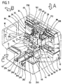
- a first embodiment shown in FIG. 1 a machine tool according to the invention comprises a Whole with 10 designated machine frame, on which a workpiece 12 can be positioned.
- a tool 14 To edit the Workpiece 12 by means of a tool 14 is the tool 14 received in a tool spindle 16, which in turn on the machine frame 10 in an X and a Y direction is movable.
- the workpiece 12 is still in a Z direction relative to the tool spindle 16 and perpendicular movable to the X and Y axes, so that the total Workpiece 12 and the tool 14 along 3 perpendicular to each other vertical axes, namely the X, Y and Z axes are movable for machining the workpiece 12.
- the tool spindle 16 is on a Y-slide 18 held, which in turn on one Carriage 20, designed as a yoke with a central opening 22 is displaceable in the Y direction. It extends the tool spindle 16 with the tool 14 facing rear section 24 (Fig. 2 and Fig. 3) through the central opening 22.
- the central opening 22 is therefore designed so that the tool spindle 16 lengthways of their maximum Y travel path, specified by the mobility of the Y carriage 18 relative to the carriage carrier 20, unimpeded, without colliding with edges of the central opening 22 is movable.
- the carriage carrier 20 is surrounded by an X carriage 26, which in turn along the X axis on a stand 28 is kept displaceable.
- the stand 28 is also formed as a yoke and has a central opening 30 through which the rear part of the tool spindle passes 24 extends therethrough, the central opening 30 is designed such that the tool spindle 16 in this in all possible positions along the X and Y axes is movable without collision.
- the stand 28 sits as part of the machine frame 10 one also included in the machine frame 10 Machine bed 32, which has a longitudinal bed 34, the parallel to the Z axis and thus perpendicular to one of the X-axis and the Y-axis spanned plane of that Stand 28 extends away.
- Machine bed 32 which has a longitudinal bed 34, the parallel to the Z axis and thus perpendicular to one of the X-axis and the Y-axis spanned plane of that Stand 28 extends away.
- the longitudinal bed 34 For a stable connection of the Stand 28 with the longitudinal bed 34 'has the machine bed 32 two legs 36 protruding from the longitudinal bed in a Y-shape, on their ends 38 facing away from the longitudinal bed 34 Stand 28 sits, the ends 38 below vertical Yoke beam 40 of the stand 28 lie.
- the axis of rotation drive 44 forms together with a receptacle 46 for a workpiece carrier 48 with one as a whole 50 designated turntable for the workpiece carrier 48, which preferably as a pallet for receiving the workpiece 12 is formed.
- the B axis is parallel to that of the X and Y axes spanned plane and is preferably perpendicular on a spindle axis 52 of the tool spindle 16.
- the Y-carriage 18 comprises a bridge 70 which carries the tool spindle 16.
- the Bridge 70 carries 72 carriages 74 on a rear side and 76, which are on a front side 78 of the sled carrier 20 spaced from each other and parallel to the Y-axis guide rails 80 and 82 are performed.
- the carriages 74 and 76 also form the guide rails 80 and 82 main guides 84 and 86 for the Y-slide 80, which is preferably symmetrical are arranged to the spindle axis 52.
- a linear motor 88 or 90 is arranged, which both together to move the Y-carriage 18 in Serve in the direction of the Y axis and simultaneously with each other operate.
- the two linear motors 88 and 90 are each on the side the carriage 20 arranged so that they next to a side surface 92 or 94 of the sled carrier 20 lie and parallel with their winding planes 96 extend to the Y and parallel to the Z direction.
- Each of the linear motors comprises a primary part 98, which on a retaining flange 100 of the Y-carriage 18 one of the side surfaces 92 and 94 facing side is mounted.
- the holding flange 100 extends here approximately parallel from an outer end 102 of the bridge 70 to the side surface 94, overlapping it.
- the primary part 98 faces the slide carrier 20 a secondary part 106 is arranged by means of a support element 104, which on the support member 104 on a Holding flange 100 facing side sits while the Support element 104 is held on the side surface 94.
- the holding flange 100 To support the retaining flange 100 against the between the primary part 98 and the secondary part 106 perpendicular to Forces acting on the winding plane 96 is the holding flange 100 on its side facing away from the bridge 70 by a Additional guide 108 guided, which one with the retaining flange 100 connected carriages 110 and one on the Side surface 94 seated and parallel to the Y axis extending longitudinal guide 112 includes.
- This additional tour 108 thus guides the holding flange 100 precisely in a defined manner Alignment with the side surface 94 of the sled carrier 20 and thus the primary part 98 in a defined Distance to the secondary section, 106 together with the Main tours 84 and 86.
- cooling channels 114 and 116 are provided, so that both the primary 98 and the secondary 106 by the respective supporting element that is called the holding flange 100 and the support member 104, coolable are.
- the cooling channels 114 and 116 are from flows through a cooling medium by a cooling device is cooled to a defined temperature.
- the two linear motors 88 and 90 are controlled via a common one for both linear motors 88 and 90 provided control 118, which is an NC axis control represents, but with separate power supplies 120, the one to be approached by the Y slide 18 Position along the Y axis from a parent Machine control 122 of the control 118 can be predetermined.
- a Y measuring system extending parallel to the Y axis 124 provided, which on the front 78 of the Carriage 20, between the tool spindle 16 and the main guide 86, sits and a displacement sensor 126 and a displacement sensor 128, the displacement sensor 126 sits on the slide carrier 20 and the displacement sensor 128 is connected to the bridge 70.
- the Y measuring system 124 detects the position of the Y carriage 18 relative to the Y axis and reports this via a line 130 of the control 118, which is thus an actual Y position which is specified after a comparison with to be approached by the machine control 122 Y position to a via a feed line 132 or 134 flowing to the respective linear motor 88 or 90 Winding current for the respective linear motor 88 or 90 leads.
- a pneumatic Counterweight 140 balanced which one Pneumatic cylinder 142 includes that on the sled carrier 20 is held and the piston rod 144 on the bridge 70 preferably engages in the area of the tool spindle 16.
- the pneumatic cylinder 142 is pressurized in such a way that he's essentially the one on the Y carriage 18 acting gravity compensates so that by means of the linear motors 88 and 90 essentially only the acceleration forces have to be applied.
- a brake shoe actuating braking member 152 which in turn is held on the bridge 70 and a brake bar 154, which on a front side 78 of the slide carrier 20th is held.
- the brake 150 serves to fix the Y-slide 20 at Actuation of an emergency stop switch or in the event of a power failure, in the latter case an actuation of the Brake 150 takes place.
- the X carriage 26 comprising the carriage carrier 20 is in turn on the yoke-like stand 28 slidably mounted, by means of two main guides 170 and 172, each with a carriage 174 and a guide rail 176, the Guide rail 176 on a front 178 of the stand 28 sits, while the guide carriage 174 on a back 180 of the X-slide 26 sits.
- the two main guides 170 and 172 are parallel aligned with the X axis and spaced from each other, preferably in the range of two one Crossbeams 184 and 186 of the slide carrier yoke-like stand 28.
- Two linear motors 190 are used to drive the X slide 26 and 192 provided, the winding plane 194 parallel to X direction and parallel to the Z direction. there the two linear motors 190 and 192 are also located to the side of the crossbeams 184 and 186, the lower one Linear motor 190 below the lower crossbar 184 and the upper linear motor 192 above the upper crossbar 186 lies.
- Each of the linear motors 190 and 192 includes one of one am X-slide 26 arranged holding flange 196 worn Primary part 198, which is opposite a secondary part 200, which in turn is held by a support element 202 which is on a side surface 204 of the crossbeams 184 or 186 is arranged.
- the holding flange 196 extends over also the side surface 204 of the respective crossbar 184 and 186 respectively.
- an additional guide 206 is provided which has a guide carriage 208 and a guide rail 210, the Guide carriage 208 on the holding flange 196 and the guide rail 210 on the respective crossbar 184 or 186 is held.
- the additional guide 206 also applies at an end of the respective one facing away from the X slide 26 Holding flange 196 on, so that the respective linear motor 190 or 192 between the additional guide 206 and the respective main guide 170 and 172 and the primary part 198 compared to the secondary part 200 by the respective Additional guide 206 and the respective main guide 170 or 172 is supported on both sides.
- the measuring system 228 near the linear motor 190, preferably on the side facing away from the stand 28 the same and the measuring system 230 is close to the linear motor 192, preferably on the side facing away from the crossbar 186 Side of the same.
- Each of the two measuring systems 228 and 230 comprises one Displacement sensor 232 and a displacement sensor 234, the displacement sensor 232 is connected to the stand 28 and the Position sensor 234 with the X slide 26.
- two brakes 250 and 252 are provided on the X axis, each of which has a brake member 254 with brake shoes and a brake bar 256, the brake bar 256 the brake 250 on the crossbar 184 and the brake bar the brake 252 are held on the crossbeam 186, while the braking members 254 of the two brakes 250 and 252 sit on the back 180 of the X-slide 26.
- Both brakes 250 and 252 are used to fix the X-slide when actuating an emergency stop switch or at Power failure provided.
- the longitudinal bed 34 comprises two spaced apart and Support beams 290 and 292 running parallel to the Z axis, which form a sled carrier and main guides 294 or 296 for the Z-carriage 42.
- Each of the main tours each includes one on the support beam 290 or 292 resting guide rail 298 and one on the Guide rail 298 movable guide carriage 300, which is held on the Z slide 42.
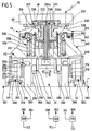
- the Z-carriage 42 comprises a housing 302 of the rotary axis drive 44, on which one is designated as a whole by 304 Rotor by means of a rotary bearing 306 about the B axis is rotatably mounted.
- the rotor 306 is directly through one with 308 as a whole designated motor driven, the stator 310 in Housing 302 is mounted and the rotor part 312 rotatable sits on the rotor, the stator part 310 and the rotor part 312 between the rotary bearing 306 and the guide carriage 300 in Housing 302 are arranged.
- this encoder 314 reports the actual rotational position of the rotor 304 relative to the Housing 302 of a control 316, which in turn via a feed line supplies the motor 308 with current, so that the Rotary movements as NC-controlled B-axis movements are feasible.
- the individual rotational positions of the motor 308 are over the Machine control 122 of the rotary axis control 316 given.
- the receptacle 46 is provided, which are spaced apart arranged roller bearing 320, which the workpiece carrier support on an underside 322. Further the roller bearings 320 engage in grooves 324 of the workpiece carrier a so that the workpiece carrier by moving the Recording 46 in the direction of the housing 302 also in acted upon in this direction and on conditions 326 on Rotor 304 is attachable.
- These pads 326 are used Centering and precise alignment of the tool carrier 48 relative to the rotor 304 by an exact positioning of the Workpiece carrier 48 relative to the rotor 304 and thus with respect the B axis and the Z axis.
- the pads 326 extend transversely to the B axis Contact surfaces and also show Centering pin 330, which in corresponding center holes 332 engage the workpiece carrier 48 to this defined with respect to the B axis to position on the rotor 304.
- a supply of the cylinder spaces 335a, b in the rotor 304 takes place through a central and a piston rod of the Piston 334 extending stationary feed 338, which itself extending from the housing 302 into the rotor 304 and at the level of the cylinder spaces 335a and 335b, the cylinder spaces 335a and 335b with their hydraulic channels via rotary feeders connects.
- a brake 340 is provided, which a Has braking member 342 and a brake flange 344, wherein the brake flange 344 is rigidly connected to the rotor 304 and the braking member 342 is firmly seated on the housing 302.
- two linear motors 360 and 362 are provided, whose Winding planes 364 are in a plane parallel to the Z and Y axis extends.
- the two linear motors 360 and 362 lie to the side of the support beams in the area mutually facing side surfaces 366 of the same.
- Each of the linear motors 360 and 362 comprises a primary part 368, which is held on a holding flange 370, wherein the holding flange 370 in turn held on the Z-slide is and the side of the support beams 290 and 292 and whose side surfaces extend over 366.
- the Opposite primary part 368 is a secondary part 372 arranged, which in turn on a support member 374 sits, which in turn on the respective side surface 366 is held.
- cooling channels 371 and 375 are provided, which in the same Like the X-axis or the Y-axis with coolant are flowed through.
- the holding flange 370 is supported by a as a whole with 376 additional guide, which one Comprises guide carriage 378 and a guide rail 380, the guide rail 380 with the respective support beam 290 or 292 is connected and the guide carriage 380 is rigidly held on the holding flange 370.
- Brakes 381 and 383 are provided, which preferably between the longitudinal bed 34 and the holding flanges 370 act, and in the same way as the brakes 250 and 252 are built up.
- each of the linear motors 360 and 362 is a measuring system 384 and 386 assigned, the measuring systems each on an inside 388 or 390 of the respective Support beams 290 and 292 are arranged to be as possible close to the respective linear motor 360 or 362 lie.
- Each of the measurement systems 384 and 386 includes a fixed one with the Longitudinal bed 34 connected transducer 392 and one with the displacement sensor 394 connected to the Z-carriage 42.
- each of these is assigned a control 396 or 398, and each of these controls 396 a position measuring system 384 or 386 for detecting the actual position in the Z direction. Both controls 396 and 398 are controlled by the Machine control 122 the position to be approached along the Z-axis, which is then compared with the actual, Compare positions sensed by measuring systems 384 and 386.
- Both controls 396 and 398 work independently of one another, so that an active parallel alignment the Z carriage can be carried out relative to the X axis, just like in connection with the controls 220 and 222 described.
- Cell 402 also includes two im Spaced side walls 406 and 408, between which the one designated as a whole with 42 Z-carriage is movable. These sidewalls 406 and 408 extend from the front wall 404 towards the can be moved both in the Y direction and in the X direction Y slide 18 with the tool spindle 16.
- Termination of cell 402 is formed by two on the X-slide 26 shields 410 and 412 held by a movement gap 414 extending in the Y direction for extend the tool spindle 16 in the X direction to the extent that they are on both sides and in all X positions of the X carriage 26 on rear side edges 416 or 418 of the side walls 406 or 408 abut or over this in the X direction on one of the working space 400 protrude opposite side.
- the two shields 410 and 412 are rigid on the X-slide 26 about a not shown in the drawing Linkage held and form a partially rear Completion of cell 402.
- the upper cover 420 is, as shown in FIG. 7, a plate held on the Y slide 18, which in grooves 424 and 426 delimiting from the movement gap 414 and edge strips 428 and 430 running in the Y direction is led.
- the extent of the plate 420 is so chosen that they have an upper edge 432 in all Y positions of the tool spindle 16 with an upper edge 434 of shields 410 and 412 closes or above this survives.
- the lower cover 422 as shown in FIG. 8, a so-called telescope cover, which a Variety of telescoping and stackable cover plates 440 which, in a large number of one behind the other in the Z direction Grooves 442 and 444 of the edge strips 428 and 430 out are.
- An uppermost one of the cover plates 440 is on the Z-slide held while a lowermost of the cover plates 440 connected to a lower part 450 of the cell 402 with the lower part 450 having a lower end cell 402.
- the two shields are 410 and 412 lightweight panels, which are two parallel to each other running outer layers 411 and one between this and connected to it, preferably glued corrugated inner layer 413 made of thin sheet metal, preferably Have aluminum sheet.
- each of the side walls 406 and 408 a door 452 or 454 provided, the respective door over a transport path 456 for the workpiece carrier 48 which is at a distance from the Y-carriage 18 and from one Machining position 458 of workpiece 14 parallel to X direction runs through cell 402.
- cell 402 Outside of cell 402 is also a whole with 460 designated tool magazine arranged, which a an axis 462 rotatable magazine wheel 464, the Axis 462 preferably runs parallel to the spindle axis 52. On this magazine wheel 464 there are receptacles on the circumference 466 arranged for a variety of tools.
- the magazine wheel 464 is arranged so that a Transfer position 468 within the Y / X travel range of the Tool spindle 16 is located so that the tool spindle 16 with the tool 14 in the transfer position 468 can move directly into the Y / X plane.
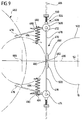
- the rear edge 416 adjoining area of side wall 406 one in detail provided double swing door 470 shown in Fig. 9, which are two axes 472 and 474 parallel to the Z axis pivotable door leaves mounted on the side wall 406 476 or 478, which in a closed Condition of the leading edges at a short distance from each other 480 or 482, so that in the closed State of the double swing door 470, the cell 402 closed is.
- These door leaves 476 and 478 are by two spring elements 484 and 486, towards their closed Position acted upon, the closed position is defined by two stops 488 and 490 against which the spring elements 484 and 486 two swivel arms 492 or create 494.
- the spring element 484 or 486 engage preferably on the swivel arms.
- the double swing door 470 is now opened by that the tool spindle 16 in a defined Y position 496 driven and then in the X direction against the door leaf 476 and 478 is driven, with the door leaves 476 and 478 for this purpose with damping elements 498 or 500, preferably 480 and 482 are provided in the area of their front edges.
- the tool spindle 16 thus presses with its outer housing 502 each of the door panels 476 and 478 in an open and 9 shown in dashed lines, moves into the Transfer position 468, transfers the tool 14 and removes a new tool after turning the magazine wheel 464 14 from the transfer position 468.
- the transfer position 468 (shown in dashed lines) is the tool spindle 16 so that its outer housing 502 the door leaf 476th and holds 478 in the open position.
- Each of the door leaves 476 and 478 is also included a friction brake 504, which is firmly attached to the respective door leaf 476 or 478 connected friction wheel 506 comprises, in turn, on a friction jaw 508, which by a resilient element 510 against the friction wheel 506 is applied, is present.
Landscapes
- Engineering & Computer Science (AREA)
- Mechanical Engineering (AREA)
- Physics & Mathematics (AREA)
- General Physics & Mathematics (AREA)
- Automation & Control Theory (AREA)
- Human Computer Interaction (AREA)
- Manufacturing & Machinery (AREA)
- Machine Tool Units (AREA)
- Automatic Tool Replacement In Machine Tools (AREA)
- Auxiliary Devices For Machine Tools (AREA)
Abstract
Description
- Fig. 1
- eine perspektivische Gesamtansicht einer erfindungsgemäßen Werkzeugmaschine;
- Fig. 2
- eine Draufsicht in Richtung eines Pfeils A in Fig. 1;
- Fig. 3
- eine Draufsicht in Richtung eines Pfeils B in Fig. 1;
- Fig. 4
- eine Draufsicht in Richtung eines Pfeils C in Fig. 1;
- Fig. 5
- einen Schnitt durch einen Z-Schlitten mit Drehachsenantrieb;
- Fig. 6
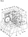
- eine perspektivische Darstellung eines zweiten Ausführungsbeispiels;
- Fig. 7
- eine ausschnittsweise geschnittene Darstellung längs Linie 7-7 in Fig. 6;
- Fig. 8
- eine ausschnittsweise geschnittene Darstellung längs Linie 8-8 in Fig. 6 und
- Fig. 9
- eine ausschnittsweise geschnittene Darstellung längs Linie 9-9 in Fig. 6.
Claims (41)
- Werkzeugmaschine, umfassend ein Maschinengestell, einen am Maschinengestell angeordneten Werkstückträger für ein zu bearbeitendes Werkstück, einen am Maschinengestell angeordneten Werkzeugträger zur Aufnahme eines Werkzeugs und mindestens einen Antrieb mit einem Schlitten zur Durchführung einer Relativbewegung zwischen dem Werkzeug und dem Werkstück in Richtung mindestens einer Achse,
dadurch gekennzeichnet, daß der Antrieb zwei parallel zu der Achse (X,Y,Z) ausgerichtete, in einer Querrichtung im Abstand voneinander angeordnete elektrische Linearmotoren (190, 192; 88, 90; 360, 362) umfaßt, daß der Schlitten (26; 18; 42) sich zwischen den beiden Linearmotoren (88, 90; 190, 192; 360, 362) erstreckt und daß eine Steuerung (220, 222; 118; 396, 398) vorgesehen ist, welche die Linearmotoren (190, 192; 88, 90; 360, 362) zum Verfahren des Schlittens (26; 18; 42) gleichzeitig betreibt. - Werkzeugmaschine nach Anspruch 1, dadurch gekennzeichnet, daß die beiden Linearmotoren (88, 90) gemeinsam als eine einzige NC-Achse (Y) betrieben werden.
- Werkzeugmaschine nach Anspruch 1, dadurch gekennzeichnet, daß die beiden Linearmotoren (190, 192; 360, 362) als voneinander unabhängige NC-Achsen (X; Z) ansteuerbar sind.
- Werkzeugmaschine nach Anspruch 3, dadurch gekennzeichnet, daß jedem Linearmotor (190, 192; 360, 362) ein eigenes Wegmeßsystem (228, 230; 384, 386) zugeordnet ist.
- Werkzeugmaschine nach Anspruch 3 oder 4, dadurch gekennzeichnet, daß der Schlitten (26; 42) aktiv gesteuert parallel verschiebbar ist.
- Werkzeugmaschine nach einem der voranstehenden Ansprüche, dadurch gekennzeichnet, daß die Linearmotoren (190, 192; 88, 90; 360, 362) jeweils beiderseits in äußeren Bereichen des Schlittens (26; 18; 42) und eines Schlittenträgers (184, 186; 20; 290, 292) angeordnet sind.
- Werkzeugmaschine nach Anspruch 6, dadurch gekennzeichnet, daß die Linearmotoren (190, 192; 88, 90; 360, 362) an jeweils gegenüberliegenden Außenseiten des Schlittenträgers (184, 186; 20; 290, 292) oder des Schlittens (26; 18; 42) angeordnet sind.
- Werkzeugmaschine nach einem der voranstehenden Ansprüche, dadurch gekennzeichnet, daß der Schlitten (26; 18; 42) an zwei zueinander parallelen und im Abstand voneinander verlaufenden Hauptführungen (170, 172; 84, 86; 294, 296) geführt ist.
- Werkzeugmaschine nach Anspruch 8, dadurch gekennzeichnet, daß die Hauptführungen (170, 172; 84, 86; 294, 296) zwischen den Linearmotoren (190, 192; 88, 90; 360, 362) angeordnet sind.
- Werkzeugmaschine nach Anspruch 8 oder 9, dadurch gekennzeichnet, daß die jeweiligen Linearmotoren (190, 192; 88, 90; 360, 362) jeweils zwischen einer Haupt-(170, 172; 84, 86; 294, 296) und einer Zusatzführung (206; 108; 376) liegen.
- Werkzeugmaschine nach einem der voranstehenden Ansprüche, dadurch gekennzeichnet, daß die Linearmotoren (190, 192; 88, 90; 360, 362) gekühlte Primär-(198; 98; 368) und Sekundärteile (200; 106; 372) aufweisen.
- Werkzeugmaschine nach Anspruch 11, dadurch gekennzeichnet, daß die Kühlung der Primär- und Sekundärteile (198, 200; 98, 106; 368, 372) durch Kühlkanäle (210, 214; 114, 116; 371, 375) in Halteelementen (196, 202; 100, 104; 370, 374) derselben erfolgt.
- Werkzeugmaschine nach Anspruch 12, dadurch gekennzeichnet, daß die Kühlkanäle (210, 214; 114, 116; 371, 375) mit einem Kühlmedium durchströmt sind, welches von einer Kühleinrichtung kühlbar ist.
- Werkzeugmaschine nach einem der voranstehenden Ansprüche, dadurch gekennzeichnet, daß der Schlitten (26; 18; 42) durch eine Bremseinrichtung (250, 252; 150; 381, 383) festlegbar ist.
- Werkzeugmaschine nach Anspruch 14, dadurch gekennzeichnet, daß der Schlitten (26; 42) durch zwei in der Querrichtung im Abstand voneinander angeordnete Bremseinrichtungen (250, 252; 381, 383) festlegbar ist.
- Werkzeugmaschine nach einem der voranstehenden Ansprüche, dadurch gekennzeichnet, daß der den Schlitten (18; 26) tragende Schlittenträger (20, 184, 186) als Joch ausgebildet ist.
- Werkzeugmaschine nach einem'der voranstehenden Ansprüche, dadurch gekennzeichnet, daß der Werkzeugträger (16) auf einem in einer Richtung (X, Y) verfahrbaren Schlitten (26; 18) gehalten ist.
- Werkzeugmaschine nach Anspruch 17, dadurch gekennzeichnet, daß der Werkstückträger (48) auf einem in einer anderen (Z) quer zur einen Richtung (X; Y) verfahrbaren Schlitten (42) gehalten ist.
- Werkzeugmaschine nach einem der voranstehenden Ansprüche, dadurch gekennzeichnet, daß der Werkstückträger mit einem Drehantrieb (50) gegenüber dem Maschinengestell (10) um eine Achse (B) drehbar ist.
- Werkzeugmaschine nach Anspruch 19, dadurch gekennzeichnet, daß der Drehantrieb (50) einen Direktantrieb (308) umfaßt.
- Werkzeugmaschine nach Anspruch 19 oder 20, dadurch gekennzeichnet, daß der Drehantrieb (50) eine Bremseinrichtung (340) aufweist.
- Werkzeugmaschine nach einem der Ansprüche 19 bis 21,
dadurch gekennzeichnet, daß der Drehantrieb als Drehtisch (50) ausgebildet ist, mit welchem der Werkstückträger (48) um eine Vertikalachse (B) drehbar ist. - Werkzeugmaschine nach Anspruch 22, dadurch gekennzeichnet, daß der Werkstückträger (48) in einer Aufnahme (46) des Drehtisches (50) lösbar und fixierbar ist.
- Werkzeugmaschine nach Anspruch 22 oder 23, dadurch gekennzeichnet, daß der Drehtisch (50) auf einem Schlitten (42) sitzt, welcher seinerseits auf einem einen Schlittenträger (290, 292) umfassenden Längsbett (34) des Maschinengestells (10) verfahrbar ist.
- Werkzeugmaschine nach einem der voranstehenden Ansprüche, dadurch gekennzeichnet, daß der Werkzeugträger als Werkzeugspindel (16) ausgebildet und auf einem Schlitten (26; 18) längs einer Achse (X; Z) verfahrbar ist.
- Werkzeugmaschine nach Anspruch 25, dadurch gekennzeichnet, daß die Werkzeugspindel (16) so an dem Schlitten (18) angeordnet ist, daß sie eine Mittelöffnung (22) des als Joch ausgebildeten Schlittenträgers (20) durchsetzt.
- Werkzeugmaschine nach Anspruch 26, dadurch gekennzeichnet, daß der Schlittenträger (20) seinerseits Teil eines Schlittens (26) und auf einem weiteren, als Joch ausgebildeten Schlittenträger (184, 186) geführt ist und daß die Werkzeugspindel (16) die Mittelöffnungen (22, 30) beider Joche durchsetzt.
- Werkzeugmaschine nach dem Oberbegriff des Anspruch 1 oder nach einem der voranstehenden Ansprüche, dadurch gekennzeichnet, daß diese einen ersten Schlitten (18) aufweist, welcher längs einer ersten Achse (Y) bewegbar und an einem ersten Schlittenträger (20) geführt ist, daß der Schlittenträger (20) Teil eines längs einer zweiten (X), quer zur ersten Achse (Y) verfahrbaren Schlittens (26) ist, welcher seinerseits an einem zweiten Schlittenträger (184, 186) geführt ist, und daß der zweite Schlittenträger (184, 186) Teil des Maschinengestells (10) ist.
- Werkzeugmaschine nach Anspruch 28, dadurch gekennzeichnet, daß das Maschinengestell (10) ein Längsbett (34) aufweist, längs welchem ein dritter Schlitten (42) längs einer dritten Achse (Z) verfahrbar ist, welche quer zu der ersten (Y) und der zweiten Achse (X) verläuft.
- Werkzeugmaschine nach dem Oberbegriff des Anspruchs 1 oder nach einem der voranstehenden Ansprüche, dadurch gekennzeichnet, daß ein Arbeitsraum (400) der Werkzeugmaschine von einer Zelle (402) umschlossen ist.
- Werkzeugmaschine nach einem der vorangehenden Ansprüche, dadurch gekennzeichnet, daß eine Begrenzung der Zelle (402) durch mindestens ein an dem Schlitten (26, 18) gehaltenes und sich von diesem weg in seiner Bewegungsrichtung (X, Y) erstreckendes Schild (410, 412; 420) gebildet ist, welches in allen Achsenpositionen des Schlittens (26, 18) sich mindestens bis zu einer Begrenzung (416, 418; 434) des Arbeitsraums (400) reicht.
- Werkzeugmaschine nach Anspruch 31, dadurch gekennzeichnet, daß die Begrenzung der Zelle (402) durch zwei sich in entgegengesetzte Richtungen erstreckende Schilde (410, 412) gebildet ist.
- Werkzeugmaschine nach Anspruch 32, dadurch gekennzeichnet, daß ein von einem zweiten Schlitten (18) getragenes Werkzeug (14) einen Bewegungsspalt (414) zwischen den beiden Schilden (410, 412) durchgreift.
- Werkzeugmaschine nach Anspruch 33, dadurch gekennzeichnet, daß der Bewegungsspalt (414) zumindest in einer Richtung durch einen von dem Schlitten (18) bewegbares Schild (420) abgedeckt ist.
- Werkzeugmaschine nach dem Oberbegriff des Anspruchs 1 oder nach einem der voranstehenden Ansprüche, dadurch gekennzeichnet, daß die Werkzeugmaschine einen von einer Zelle (402) umschlossenen Arbeitsraum (400) und ein außerhalb der Zelle (402) angeordnetes Werkzeugmagazin (460) aufweist.
- Werkzeugmaschine nach einem der vorangehenden Ansprüche, dadurch gekennzeichnet, daß eine zwischen dem Arbeitsraum (400) und dem Werkzeugmagazin (460) liegende Seitenwand (406) der Zelle (402) mit einer Schwingtür (470) versehen ist.
- Werkzeugmaschine nach Anspruch 36 dadurch gekennzeichnet, daß die Schwingtür als Doppelschwingtür (370) mit zwei Türflügeln (476, 478) versehen ist.
- Werkzeugmaschine nach Anspruch 37, dadurch gekennzeichnet, daß die Türflügel (476, 478) durch Beaufschlagung von dem Werkzeugträger (16) in eine geöffnete Stellung bringbar sind.
- Werkzeugmaschine nach Anspruch 38, dadurch gekennzeichnet, daß an den Türflügeln (476, 478) Dämpfungselemente (498, 500) vorgesehen sind.
- Werkzeugmaschine nach einem der Ansprüche 37 bis 39, dadurch gekennzeichnet, daß die Türflügel (476, 478) mittels Federelementen (484, 486) in Richtung ihrer geschlossenen Stellung beaufschlagt sind.
- Werkzeugmaschine nach einem der Ansprüche 37 bis 40, dadurch gekennzeichnet, daß jeder Türflügel (476, 478) mit einer Bremseinrichtung (504) versehen ist.
Applications Claiming Priority (3)
| Application Number | Priority Date | Filing Date | Title |
|---|---|---|---|
| DE4307482 | 1993-03-10 | ||
| DE4307482A DE4307482A1 (de) | 1993-03-10 | 1993-03-10 | Werkzeugmaschine |
| EP94103373A EP0614724B2 (de) | 1993-03-10 | 1994-03-05 | Werkzeugmaschine |
Related Parent Applications (2)
| Application Number | Title | Priority Date | Filing Date |
|---|---|---|---|
| EP94103373A Division EP0614724B2 (de) | 1993-03-10 | 1994-03-05 | Werkzeugmaschine |
| EP94103373.0 Division | 1994-03-05 |
Publications (3)
| Publication Number | Publication Date |
|---|---|
| EP1155771A2 true EP1155771A2 (de) | 2001-11-21 |
| EP1155771A3 EP1155771A3 (de) | 2004-07-21 |
| EP1155771B1 EP1155771B1 (de) | 2007-07-18 |
Family
ID=6482382
Family Applications (2)
| Application Number | Title | Priority Date | Filing Date |
|---|---|---|---|
| EP94103373A Expired - Lifetime EP0614724B2 (de) | 1993-03-10 | 1994-03-05 | Werkzeugmaschine |
| EP01119020A Revoked EP1155771B1 (de) | 1993-03-10 | 1994-03-05 | Werkzeugmaschine |
Family Applications Before (1)
| Application Number | Title | Priority Date | Filing Date |
|---|---|---|---|
| EP94103373A Expired - Lifetime EP0614724B2 (de) | 1993-03-10 | 1994-03-05 | Werkzeugmaschine |
Country Status (5)
| Country | Link |
|---|---|
| US (2) | US5688084A (de) |
| EP (2) | EP0614724B2 (de) |
| JP (1) | JPH06297286A (de) |
| DE (3) | DE4307482A1 (de) |
| ES (2) | ES2170754T5 (de) |
Cited By (2)
| Publication number | Priority date | Publication date | Assignee | Title |
|---|---|---|---|---|
| EP1342532A2 (de) * | 2002-03-05 | 2003-09-10 | DECKEL MAHO Pfronten GmbH | Werkzeugmaschine mit Bremseinrichtung für ein Maschinenteil |
| WO2010000457A1 (de) | 2008-07-03 | 2010-01-07 | Ex-Cell-O Gmbh | Bearbeitungsanlage für werkstücke |
Families Citing this family (135)
| Publication number | Priority date | Publication date | Assignee | Title |
|---|---|---|---|---|
| DE4430113A1 (de) * | 1994-08-25 | 1996-02-29 | Berliner Werkzeugmasch | Werkzeugmaschine |
| JPH08267329A (ja) * | 1995-01-31 | 1996-10-15 | Kyocera Corp | 位置決め装置 |
| DE19516849C2 (de) * | 1995-05-11 | 1997-09-25 | Chiron Werke Gmbh | Maschinenzentrum mit Werkzeugmaschinen und einer Ladevorrichtung |
| US5662568A (en) * | 1995-05-12 | 1997-09-02 | Ingersoll Milling Machine Co. | Symmetrical multi-axis linear motor machine tool |
| IT1279651B1 (it) * | 1995-10-11 | 1997-12-16 | Selco Srl | Macchina sezionatrice di pezzi. |
| FR2743741B1 (fr) * | 1996-01-23 | 1998-03-06 | Renault Automation | Structure logique d'une machine-outil d'usinage a grande vitesse du type porte-broche |
| JP3540091B2 (ja) * | 1996-03-29 | 2004-07-07 | 株式会社森精機製作所 | 工作機械 |
| FR2756763B1 (fr) * | 1996-12-09 | 1999-02-26 | Helis Sa | Machine-outil a portique et a broche verticale |
| WO1998035783A1 (fr) * | 1997-02-12 | 1998-08-20 | Bando Kiko Co., Ltd. | Appareil d'usinage de feuilles de verre |
| FR2760670B1 (fr) * | 1997-03-13 | 1999-06-11 | Lionel Gaiani | Centre d'usinage a 4 et 5 axes tres grande vitesse |
| JPH10249666A (ja) * | 1997-03-17 | 1998-09-22 | Toyoda Mach Works Ltd | 工作機械 |
| JP3507938B2 (ja) * | 1997-03-18 | 2004-03-15 | 豊田工機株式会社 | リニアモータ駆動方法 |
| JPH10263960A (ja) * | 1997-03-19 | 1998-10-06 | Mori Seiki Co Ltd | 工作機械 |
| US6086295A (en) * | 1997-06-30 | 2000-07-11 | Novak; Norm | Automated flash removing apparatus |
| DE69838351T2 (de) * | 1997-07-24 | 2008-05-21 | Jtekt Corp., Osaka | Werkzeugmaschine |
| JP3847437B2 (ja) * | 1998-02-04 | 2006-11-22 | 株式会社ジェイテクト | リニアモータ駆動式工作機械 |
| JP3509479B2 (ja) * | 1997-07-24 | 2004-03-22 | 豊田工機株式会社 | 工作機械 |
| DE19732608B4 (de) | 1997-07-29 | 2004-04-15 | Ex-Cell-O Gmbh | Werkzeugmaschine |
| DE19737478C1 (de) * | 1997-08-28 | 1998-12-17 | Saechsische Werkzeug Und Sonde | Lagerung für ein mit Linearmotoren beidseitig angetriebenes Werkzeugmaschinen-Portal |
| US5957637A (en) * | 1997-11-13 | 1999-09-28 | Micro Optics Design Corp. | Apparatus and method for generating ultimate surfaces on ophthalmic lenses |
| JP3497071B2 (ja) * | 1997-11-20 | 2004-02-16 | 東芝機械株式会社 | 輪郭加工方法および加工機械 |
| FR2771324B1 (fr) * | 1997-11-27 | 2000-02-18 | Renault Automation | Procede d'allongement de la course d'usinage d'une machine-outil, dispositif permettant de le mettre en oeuvre et machine-outil utilisant un tel dispositif |
| JP3482331B2 (ja) * | 1997-12-17 | 2003-12-22 | 東芝機械株式会社 | 仕上げ加工方法 |
| US6204585B1 (en) | 1997-12-19 | 2001-03-20 | Riello Macchine Transfer Srl | Work unit having an integrally mounted drive unit |
| IT1296889B1 (it) * | 1997-12-19 | 1999-08-02 | Riello Macchine Utensili Spa | Unita' di lavoro per macchina utensile con motore elettrico lineare di movimento assiale del mandrino |
| WO1999037429A1 (en) * | 1998-01-27 | 1999-07-29 | General Electro Mechanical Corporation | Apparatus and method for positioning tooling |
| DE19803563C1 (de) * | 1998-01-30 | 1999-04-08 | Weisser Soehne J G | Werkzeugmaschine, insbesondere Drehmaschine mit wenigstens einer hängend angeordneten horizontalen Arbeitsspindel |
| JPH11340695A (ja) * | 1998-05-25 | 1999-12-10 | Sony Corp | 組立装置 |
| DE19833125A1 (de) * | 1998-07-23 | 2000-01-27 | Actech Gmbh Adv Casting Tech | Flächenportalsystem mit linearen Direktantrieben |
| DE19934291B4 (de) * | 1998-08-07 | 2004-08-26 | Karl-Heinz Wiemers | Verfahren und Vorrichtung zur mechanischen Bearbeitung von Werkstücken und zur Montage/Demontage von Baugruppen |
| US6138818A (en) * | 1998-11-23 | 2000-10-31 | Green Technologies Inc. | Workpiece inversion system for milling machines |
| DE19853942C1 (de) * | 1998-11-24 | 2000-07-13 | Festo Ag & Co | Elektrischer Linearantrieb |
| US6074281A (en) * | 1998-11-30 | 2000-06-13 | Dac Vision, Inc. | Fining and polishing machine and method for ophthalmic lenses |
| JP3315945B2 (ja) | 1998-12-02 | 2002-08-19 | 株式会社ソディック | 放電加工装置の軸送り装置 |
| DE19857013C2 (de) * | 1998-12-09 | 2001-09-06 | Schwaebische Werkzeugmaschinen | Werkzeugmaschine mit horizontaler Arbeitsspindel |
| JP2000218443A (ja) * | 1999-01-28 | 2000-08-08 | Sodick Co Ltd | 放電加工の送り装置 |
| US6048143A (en) * | 1999-01-30 | 2000-04-11 | Industrial Technology Research Institute | Composite mechanism multi-axis machine tool |
| DE19918082B4 (de) * | 1999-04-21 | 2005-09-08 | Deckel Maho Gmbh | Universal-Werkzeugmaschine |
| DE29907963U1 (de) * | 1999-05-05 | 1999-07-29 | Honsberg Lamb Sonderwerkzeugmaschinen | Werkzeugmaschine zum Bearbeiten von Kurbelwellen |
| WO2000076704A1 (en) * | 1999-06-11 | 2000-12-21 | Unova I.P. Corporation | Machine tool drive system |
| AT410293B (de) * | 1999-06-23 | 2003-03-25 | Krause & Co Ernst | Linearantrieb für schlittensysteme von werkzeugmaschinen |
| US6140606A (en) * | 1999-07-23 | 2000-10-31 | Lillbacka Jetair Oy | Laser cutting system |
| FR2800000B1 (fr) * | 1999-10-20 | 2002-01-18 | Renault Automation Comau | Dispositif de separation entre le poste d'usinage et le poste d'entrainement d'une machine-outil et machine-outil adaptee a un tel dispositif |
| DE69914377T2 (de) | 1999-11-19 | 2004-11-04 | Makino Milling Machine Co. Ltd. | Numerisch gesteuerte werkzeugmaschine |
| FR2802136B1 (fr) * | 1999-12-13 | 2002-02-22 | Renault Automation Comau | Dispositif de protection des moyens d'entrainement et de guidage d'un organe mobile d'une machine-outil contre les projections de copeaux |
| EP1122023A1 (de) * | 2000-02-02 | 2001-08-08 | Maschinenfabrik Berthold Hermle Aktiengesellschaft | Bearbeitungsmaschine zum Drehen und Fräsen |
| EP1122008A1 (de) * | 2000-02-02 | 2001-08-08 | Maschinenfabrik Berthold Hermle Aktiengesellschaft | Bearbeitungsmaschine mit einem Trommelmagazin zur Aufnahme von Werkzeugen |
| JP3353083B2 (ja) | 2000-05-10 | 2002-12-03 | ホーコス株式会社 | コラム固定形工作機械 |
| WO2001094070A1 (fr) | 2000-06-09 | 2001-12-13 | Makino Milling Machine Co., Ltd. | Dispositif de machine-outil et procede de remplacement de la palette dudit dispositif |
| DE10030229A1 (de) * | 2000-06-20 | 2002-01-03 | Heller Geb Gmbh Maschf | Linearführung für elektrische Linearmotoren |
| DE50102146D1 (de) | 2000-06-29 | 2004-06-03 | Hueller Hille Gmbh | Werkzeug-maschine zur mindestens 3-achsigen bearbeitung von werkstücken |
| ITBO20000516A1 (it) * | 2000-09-06 | 2002-03-06 | Jobs Spa | Macchina utensile |
| DE10050141C2 (de) * | 2000-10-11 | 2002-11-14 | Ds Technologie Werkzeugmaschb | Ständerwerkzeugmaschine |
| JP3357947B2 (ja) * | 2000-10-12 | 2002-12-16 | ホーコス株式会社 | 工作機械 |
| DE20019035U1 (de) * | 2000-11-08 | 2001-01-18 | Waldrich Werkzeugmasch | Werkzeugmaschine, insbesondere Hochgeschwindigkeits-Bearbeitungszentrum |
| JP2002181972A (ja) * | 2000-11-21 | 2002-06-26 | Schlumberger Technologies Inc | X−yステージ用モータ式駆動装置 |
| FI109411B (fi) * | 2000-12-04 | 2002-07-31 | Lillbacka Jetair Oy | Menetelmä levytyökeskuksessa ja levytyökeskus |
| ES2241703T3 (es) * | 2001-03-09 | 2005-11-01 | Cross Huller Gmbh | Maquina herramienta. |
| JP3768825B2 (ja) * | 2001-03-29 | 2006-04-19 | キヤノン株式会社 | 電磁アクチュエータ、リニアモータ、露光装置、半導体デバイス製造方法、半導体製造工場および露光装置の保守方法 |
| EP1270145A3 (de) * | 2001-06-22 | 2004-02-11 | Traub Drehmaschinen GmbH | Werkzeugmaschine mit einem drehbaren Mehrfachwerkzeugträger |
| US6685228B2 (en) * | 2001-06-29 | 2004-02-03 | Laser Band, Llc | Self-laminating strip label and method for assembling same |
| JP4179493B2 (ja) * | 2001-09-21 | 2008-11-12 | 株式会社ジェイテクト | 回動自在な主軸ヘッドを備えた工作機械 |
| JP3657905B2 (ja) * | 2001-11-09 | 2005-06-08 | 株式会社ソディック | 放電加工の送り装置 |
| JP2002192426A (ja) * | 2001-11-16 | 2002-07-10 | Sodick Co Ltd | 放電加工の送り装置 |
| US6591757B1 (en) * | 2001-12-26 | 2003-07-15 | Anorad Corporation | Motor driven high stability brake for linear motion systems |
| CZ298615B6 (cs) * | 2002-01-11 | 2007-11-28 | Výrobní stroj, zejména obrábecí | |
| DE10215241B4 (de) * | 2002-04-06 | 2011-11-17 | Mag Ias Gmbh | Paletten-Wechseleinrichtung für eine Werkzeugmaschine |
| AU2003233599A1 (en) * | 2002-05-17 | 2003-12-02 | Anthony Salerno Jr. | Linear electric servo motor actuated screw thread tapper |
| ITBO20020400A1 (it) * | 2002-06-21 | 2003-12-22 | Jobs Spa | Macchina utensile |
| DE20304653U1 (de) * | 2002-07-09 | 2004-03-18 | Grob-Werke Burkhart Grob E.K. | Bearbeitungsstation |
| KR101031289B1 (ko) * | 2002-07-09 | 2011-04-27 | 그롭-베르케 게엠베하 운트 코. 카게 | 가공편 캐리지를 갖는 가공 스테이션 |
| DE10245058B4 (de) * | 2002-09-26 | 2005-05-25 | Kurt Kessler | Programmgesteuerte Werkzeugmaschine |
| US6798088B2 (en) * | 2002-11-07 | 2004-09-28 | Industrial Technology Research Institute | Structure for symmetrically disposed linear motor operated tool machine |
| DE20301126U1 (de) * | 2003-01-25 | 2003-03-27 | Hueller Hille Gmbh | Doppelspindel-Werkzeugmaschine |
| JP2004319697A (ja) * | 2003-04-15 | 2004-11-11 | Disco Abrasive Syst Ltd | 板状物に形成された電極の加工装置 |
| EP1477267A3 (de) * | 2003-05-14 | 2004-12-22 | Toyoda Koki Kabushiki Kaisha | Werkzeugmaschine mit linearmotoren |
| DE10357585A1 (de) * | 2003-07-02 | 2005-07-07 | Lat Suhl Ag | Verbesserter planarer Direktantrieb mit einem Positionsmesssystem |
| JP4409867B2 (ja) | 2003-07-15 | 2010-02-03 | 株式会社森精機製作所 | 工作機械の配索構造 |
| JP4331525B2 (ja) | 2003-07-18 | 2009-09-16 | アイシン・エィ・ダブリュ株式会社 | マシニングセンタ |
| DE10337547A1 (de) * | 2003-08-05 | 2005-03-03 | Ex-Cell-O Gmbh | Werkzeugwechselvorrichtung für eine Werkzeugmaschine und Verfahren zum Werkzeugwechsel an einer Werkzeugmaschine |
| US20050107004A1 (en) * | 2003-11-13 | 2005-05-19 | Brampton Brick Limited | Method and apparatus for removing flash from a brick |
| TWI326631B (en) * | 2004-04-28 | 2010-07-01 | Sankyo Seisakusho Kk | Machine tool and detachable/attachable motor |
| JP4427689B2 (ja) * | 2004-07-08 | 2010-03-10 | オークマ株式会社 | 工作機械 |
| FR2874525B1 (fr) * | 2004-09-01 | 2008-01-25 | Oger Soc Par Actions Simplifie | Installation pour l'usinage par commande numerique de pieces |
| JP4575134B2 (ja) * | 2004-12-20 | 2010-11-04 | 株式会社ソディック | 放電加工用電極及び放電加工法 |
| TWM269987U (en) * | 2005-01-07 | 2005-07-11 | Suen Cin Entpr Co Ltd | C-shaped machining center for symmetric workpiece |
| DE102006015101B4 (de) * | 2005-04-01 | 2010-10-07 | Mori Seiki Co., Ltd., Yamatokoriyama-shi | Werkzeugwechsler einer Werkzeugmaschine |
| JP4410140B2 (ja) * | 2005-04-06 | 2010-02-03 | 株式会社森精機製作所 | 工作機械 |
| GB0508695D0 (en) * | 2005-04-29 | 2005-06-08 | Univ Cranfield | Apparatus and method |
| DE102005058347B4 (de) * | 2005-12-06 | 2014-10-23 | Schwäbische Werkzeugmaschinen GmbH | Werkzeugmaschine zur Bearbeitung von Werkstücken |
| WO2007099632A1 (ja) * | 2006-03-02 | 2007-09-07 | Pascal Engineering Corporation | 工作機械用主軸バランサ |
| DE102006011551A1 (de) * | 2006-03-10 | 2007-09-13 | Haas Schleifmaschinen Gmbh | Werkzeugmaschine |
| ES2306325T3 (es) * | 2006-05-03 | 2008-11-01 | Ligmatech Automationssysteme Gmbh | Prensa de cuerpos. |
| DE102006034123B4 (de) * | 2006-07-24 | 2009-02-12 | Deckel Maho Seebach Gmbh | Fräs- und Bohrmaschine sowie Werkstücktischanordnung |
| FR2907355B1 (fr) * | 2006-10-20 | 2009-05-22 | Comau France Sa | Machine-outil. |
| AU2006243883B2 (en) * | 2006-11-28 | 2012-12-06 | John Mayfield | Method and apparatus for machining workpieces |
| JP2010517803A (ja) * | 2007-02-13 | 2010-05-27 | ポール エイチ. ナイ, | パーソナルアフェクターマシーン |
| US8069748B1 (en) | 2007-05-24 | 2011-12-06 | Prefix Corporation | XY linear slide mechanism |
| DE202007013008U1 (de) | 2007-09-07 | 2009-01-29 | Ex-Cell-O Gmbh | Werkzeugmaschine mit Palettenwechseleinrichtung |
| DE102007044288B4 (de) | 2007-09-07 | 2017-06-22 | Mag Ias Gmbh | Werkzeugmaschine mit einem ersten und einem zweiten Werkstückträger und Werkstückbearbeitungsverfahren |
| DE102007044290A1 (de) | 2007-09-07 | 2009-03-12 | Ex-Cell-O Gmbh | Werkzeugmaschine mit mindestens einer Schiebetür |
| DE102007044282A1 (de) | 2007-09-07 | 2009-03-12 | Ex-Cell-O Gmbh | Werkzeugmaschine mit beweglichen Werkstückschlitten |
| JP5498943B2 (ja) * | 2007-09-14 | 2014-05-21 | フレックスリンク コンポーネンツ アーベー | コンベアシステムのための持ち上げ装置、コンベアシステムおよび方法 |
| JP4466711B2 (ja) * | 2007-10-10 | 2010-05-26 | 株式会社デンソー | ワーク搬送装置 |
| JP5191211B2 (ja) * | 2007-10-31 | 2013-05-08 | 株式会社ジェイテクト | マシニングセンタ |
| US20100054887A1 (en) * | 2008-08-28 | 2010-03-04 | Feng-Tien Chen | Machine tool with a plurality of worktables |
| DE102008058161A1 (de) | 2008-11-12 | 2010-05-20 | Ex-Cell-O Gmbh | Werkzeugmaschine mit schwimmend gelagerter Trägereinrichtung |
| DE102009011672A1 (de) * | 2009-01-16 | 2010-07-22 | Wieland Dental + Technik Gmbh & Co. Kg | Bearbeitungsmaschine |
| DE102009032834B4 (de) | 2009-07-07 | 2011-09-22 | Mag Ias Gmbh | Werkzeugmaschinensystem |
| IT1398614B1 (it) * | 2009-08-05 | 2013-03-08 | Camozzi Machine Tools S P A Ora Innse Berardi S P A | Macchina combinata per barenatura e fresa- alesatura |
| US8920080B2 (en) * | 2011-03-24 | 2014-12-30 | Dmg Mori Seiki Co., Ltd. | Machine tool |
| US8784155B2 (en) * | 2011-05-16 | 2014-07-22 | Huaizhong Guo | Multi-carriage symmetrical numerically controlled coordinate grinding machine |
| CN102328234A (zh) * | 2011-08-04 | 2012-01-25 | 四川欧曼机械有限公司 | 新型多轴加工机械 |
| EP2684643A3 (de) * | 2012-05-22 | 2014-04-16 | Schneider GmbH & Co. KG | Vorrichtung und Verfahren zur Bearbeitung eines optischen Werkstücks |
| CN102909610B (zh) * | 2012-11-01 | 2014-12-17 | 哈尔滨工业大学 | 五轴联动超精密机床 |
| DE102012023619A1 (de) * | 2012-12-04 | 2014-06-05 | Ops-Ingersoll Funkenerosion Gmbh | Hochdynamische Kleinmaschine |
| WO2014169994A1 (de) * | 2013-04-15 | 2014-10-23 | Schneider Gmbh & Co. Kg | Vorrichtung und verfahren zum bearbeiten, insbesondere schleifen, eines optischen werkstücks |
| DE102013006522B4 (de) * | 2013-04-16 | 2018-04-26 | Emag Holding Gmbh | Doppelspindlige Werkzeugmaschine |
| US20150014909A1 (en) * | 2013-07-12 | 2015-01-15 | Powerhouse Mechanical Repair, Inc. | Portable machining apparatus |
| CN104416406B (zh) * | 2013-09-11 | 2017-03-01 | 富鼎电子科技(嘉善)有限公司 | 进给装置及采用该进给装置的双轴加工机 |
| US20150098771A1 (en) * | 2013-10-09 | 2015-04-09 | King Fahd University Of Petroleum And Minerals | Desktop milling machine with ovate-shaped bridge |
| DE102014201060A1 (de) | 2014-01-22 | 2015-07-23 | Broetje-Automation Gmbh | Faserlegemaschine und Verfahren zur Herstellung von Fasergelegen |
| JP6384204B2 (ja) * | 2014-08-29 | 2018-09-05 | ブラザー工業株式会社 | 工作機械 |
| US9950400B2 (en) * | 2015-01-02 | 2018-04-24 | Kinetigear, Llc | Fabrication system and method of using the same |
| JP6462889B2 (ja) * | 2015-09-30 | 2019-01-30 | 株式会社牧野フライス製作所 | マシニングセンタ |
| CN106346258B (zh) * | 2016-10-31 | 2018-07-31 | 佛山市南海正一金属建材有限公司 | 一种可将铝条定量切割且压制成片状的自动加工线 |
| JP7061431B2 (ja) * | 2017-01-30 | 2022-04-28 | 株式会社ジェイテクト | 工作機械 |
| CN107154715B (zh) * | 2017-06-09 | 2019-12-03 | 宁波亿文特自动化科技有限公司 | 永磁直线电机多轴定位装置 |
| CN107322062A (zh) * | 2017-07-31 | 2017-11-07 | 中信戴卡股份有限公司 | 一种风动铣车轮帽口毛刺装置 |
| WO2019222143A1 (en) * | 2018-05-14 | 2019-11-21 | Modig Machine Tool US Inc. | Invertible part loading system |
| CN108818135B (zh) * | 2018-09-14 | 2020-08-07 | 安徽省临泉县智创精机有限公司 | 一种数控机床用防护门 |
| DE102018130925A1 (de) * | 2018-12-05 | 2020-06-10 | Stama Maschinenfabrik Gmbh | Werkzeugmaschine mit Werkzeugspindel und Ladeportal |
| KR102044527B1 (ko) * | 2019-07-25 | 2019-11-13 | 박종기 | 수평 가공장치 |
| CN112025404B (zh) * | 2020-09-30 | 2021-06-18 | 杭州职业技术学院 | 一种自带注入润滑油的数控机床 |
| JPWO2022219772A1 (de) * | 2021-04-15 | 2022-10-20 |
Citations (13)
| Publication number | Priority date | Publication date | Assignee | Title |
|---|---|---|---|---|
| DE2358421A1 (de) * | 1972-11-25 | 1974-06-06 | Fujitsu Fanuc Ltd | Linearer schrittmotor |
| JPS58186364A (ja) * | 1982-04-21 | 1983-10-31 | Matsushita Electric Ind Co Ltd | Xyリニアモ−タ装置 |
| US4505464A (en) * | 1983-03-28 | 1985-03-19 | Anorad Corporation | High precision workpiece positioning table |
| US4595870A (en) * | 1984-08-07 | 1986-06-17 | Anorad Corporation | Linear motor |
| JPS61136753A (ja) * | 1984-12-04 | 1986-06-24 | Omron Tateisi Electronics Co | リニアモ−タ |
| US4749921A (en) * | 1986-07-21 | 1988-06-07 | Anwar Chitayat | Linear motor with non-magnetic armature |
| US4798985A (en) * | 1987-02-17 | 1989-01-17 | Anwar Chitavat | Linear motor with air-lift bearing unloading |
| US4812725A (en) * | 1987-10-16 | 1989-03-14 | Anwar Chitayat | Positioning device with dual linear motor |
| US4834353A (en) * | 1987-10-19 | 1989-05-30 | Anwar Chitayat | Linear motor with magnetic bearing preload |
| US4987668A (en) * | 1989-01-25 | 1991-01-29 | Dixi S.A. | Machine-tool |
| EP0420735A1 (de) * | 1989-09-27 | 1991-04-03 | Helis S.A. | Werkzeugmaschine mit Ständer und waagerechter Spindel |
| JPH04158509A (ja) * | 1990-10-23 | 1992-06-01 | Canon Inc | 精密移動テーブル |
| JPH04365529A (ja) * | 1991-06-14 | 1992-12-17 | Toyoda Mach Works Ltd | 工作機械 |
Family Cites Families (39)
| Publication number | Priority date | Publication date | Assignee | Title |
|---|---|---|---|---|
| DE241220C (de) * | ||||
| US3188891A (en) * | 1963-01-08 | 1965-06-15 | Giddings & Lewis | Machine tool |
| FR2290981A1 (fr) * | 1974-07-01 | 1976-06-11 | Romeu Ramon | Fraiseuse universelle |
| IT1042089B (it) * | 1974-09-11 | 1980-01-30 | Marchot J | Elemento di costruzione per pare ti divisorie portanti o muri portanti di edificio |
| US4033386A (en) * | 1975-12-18 | 1977-07-05 | Western Electric Company, Inc. | Wiring head with resiliently locked and resettable guide tube mounting assembly |
| US4030527A (en) * | 1976-06-21 | 1977-06-21 | Xynetics, Inc. | Automatic cable forming system |
| FR2382792A1 (fr) * | 1977-03-04 | 1978-09-29 | Guimbal Jean | Moteur lineaire prismatique a grande vitesse et a tres grande puissance massique |
| US4171493A (en) * | 1977-10-31 | 1979-10-16 | Linear International Corporation | Integral braking system for linear induction motor |
| DD134900A1 (de) * | 1978-02-28 | 1979-03-28 | Eberhard Riessland | Zweikoordinatenpositioniereinrichtung |
| DE2907050C2 (de) * | 1979-02-23 | 1984-08-30 | Aeg-Elotherm Gmbh, 5630 Remscheid | Funkenerosionsmaschine |
| US4382395A (en) * | 1981-04-02 | 1983-05-10 | Thomas Haar | Loading device for a machine tool, particularly for machining panels of sheet metal or other materials |
| JPS58165950A (ja) * | 1982-03-24 | 1983-10-01 | Hitachi Seiki Co Ltd | マシニングセンタのカバ−自動開閉装置 |
| US4733143A (en) * | 1982-06-01 | 1988-03-22 | Anorad Corporation | Linear motor |
| US4761573A (en) * | 1982-06-01 | 1988-08-02 | Anwar Chitayat | Linear motor |
| US4560911A (en) * | 1982-06-01 | 1985-12-24 | Anorad Corporation | Positioning table and linear motor |
| FR2530173B1 (fr) * | 1982-07-14 | 1987-08-14 | Kuka Schweissanlagen & Roboter | Procede et montage pour freiner une partie de machine et pour l'arreter |
| US4512068A (en) * | 1982-08-23 | 1985-04-23 | Cincinnati Milacron Inc. | Pallet receiver with compliant pin and socket registration |
| DE3320738A1 (de) * | 1983-06-09 | 1984-12-13 | Chiron-Werke Gmbh, 7200 Tuttlingen | Verkleidung einer werkzeugmaschine mit einer beschickungstuer |
| JPH081982B2 (ja) * | 1985-04-17 | 1996-01-10 | 株式会社日立製作所 | 電子部品搭載方法及び装置 |
| JPS61293740A (ja) * | 1985-06-21 | 1986-12-24 | Hiroshi Teramachi | テ−ブル移送装置 |
| JPS6234745A (ja) * | 1985-08-06 | 1987-02-14 | Toshiba Corp | テ−ブル装置 |
| DD241220A1 (de) * | 1985-09-30 | 1986-12-03 | Werkzeugmasch Forschzent | Drehfalttor fuer arbeitsraum-einhausungen |
| GB2194907A (en) * | 1986-09-10 | 1988-03-23 | W R Vaughan & Associates Limit | Machine tools and automatic loading equipment therefor |
| US4742609A (en) * | 1986-10-27 | 1988-05-10 | Manuflex Corporation | Automatic metal machining center system |
| US4839545A (en) * | 1987-10-16 | 1989-06-13 | Anwar Chitayat | Cooling system for linear motor |
| US4985651A (en) * | 1987-10-19 | 1991-01-15 | Anwar Chitayat | Linear motor with magnetic bearing preload |
| US4890241A (en) * | 1987-10-26 | 1989-12-26 | Megamation Incorporated | Robotic system |
| JPH01257544A (ja) * | 1988-04-08 | 1989-10-13 | Fanuc Ltd | コラム移動型切削加工機械 |
| US4833765A (en) * | 1988-05-26 | 1989-05-30 | Ford Motor Company | Method and apparatus for mechanically locating a close-fitting part within a receptacle |
| JPH027929U (de) * | 1988-06-27 | 1990-01-18 | ||
| JPH02106247A (ja) * | 1988-10-17 | 1990-04-18 | Makino Milling Mach Co Ltd | 横形マシニングセンタ |
| NL8902471A (nl) * | 1989-10-05 | 1991-05-01 | Philips Nv | Tweetraps positioneerinrichting. |
| JPH0457635A (ja) * | 1990-06-25 | 1992-02-25 | Kitamura Mach Co Ltd | 工作機械 |
| DE9018156U1 (de) * | 1990-08-07 | 1997-03-06 | Atg Test Systems Gmbh | Mehrspindelmaschine zum Bohren, Fräsen o.dgl. |
| JP3159266B2 (ja) * | 1991-02-14 | 2001-04-23 | 三洋電機株式会社 | 作業装置 |
| US5321874A (en) * | 1992-07-31 | 1994-06-21 | Ford Motor Company | Multi-positioner machining system |
| US5314397A (en) * | 1992-07-31 | 1994-05-24 | Ford Motor Company | Positioning apparatus for multiple-spindle machining |
| US5346345A (en) * | 1992-07-31 | 1994-09-13 | Ford Motor Company | High-force linear motor assembly using tandem axes |
| US5250880A (en) * | 1992-10-22 | 1993-10-05 | Ford Motor Company | Linear motor control system and method |
-
1993
- 1993-03-10 DE DE4307482A patent/DE4307482A1/de not_active Ceased
-
1994
- 1994-03-05 EP EP94103373A patent/EP0614724B2/de not_active Expired - Lifetime
- 1994-03-05 DE DE59410454T patent/DE59410454D1/de not_active Revoked
- 1994-03-05 ES ES94103373T patent/ES2170754T5/es not_active Expired - Lifetime
- 1994-03-05 DE DE59410022T patent/DE59410022D1/de not_active Expired - Lifetime
- 1994-03-05 EP EP01119020A patent/EP1155771B1/de not_active Revoked
- 1994-03-05 ES ES01119020T patent/ES2288493T3/es not_active Expired - Lifetime
- 1994-03-10 JP JP6039553A patent/JPH06297286A/ja active Pending
-
1995
- 1995-05-30 US US08/454,424 patent/US5688084A/en not_active Expired - Lifetime
-
1997
- 1997-08-05 US US08/906,301 patent/US5933933A/en not_active Expired - Fee Related
Patent Citations (13)
| Publication number | Priority date | Publication date | Assignee | Title |
|---|---|---|---|---|
| DE2358421A1 (de) * | 1972-11-25 | 1974-06-06 | Fujitsu Fanuc Ltd | Linearer schrittmotor |
| JPS58186364A (ja) * | 1982-04-21 | 1983-10-31 | Matsushita Electric Ind Co Ltd | Xyリニアモ−タ装置 |
| US4505464A (en) * | 1983-03-28 | 1985-03-19 | Anorad Corporation | High precision workpiece positioning table |
| US4595870A (en) * | 1984-08-07 | 1986-06-17 | Anorad Corporation | Linear motor |
| JPS61136753A (ja) * | 1984-12-04 | 1986-06-24 | Omron Tateisi Electronics Co | リニアモ−タ |
| US4749921A (en) * | 1986-07-21 | 1988-06-07 | Anwar Chitayat | Linear motor with non-magnetic armature |
| US4798985A (en) * | 1987-02-17 | 1989-01-17 | Anwar Chitavat | Linear motor with air-lift bearing unloading |
| US4812725A (en) * | 1987-10-16 | 1989-03-14 | Anwar Chitayat | Positioning device with dual linear motor |
| US4834353A (en) * | 1987-10-19 | 1989-05-30 | Anwar Chitayat | Linear motor with magnetic bearing preload |
| US4987668A (en) * | 1989-01-25 | 1991-01-29 | Dixi S.A. | Machine-tool |
| EP0420735A1 (de) * | 1989-09-27 | 1991-04-03 | Helis S.A. | Werkzeugmaschine mit Ständer und waagerechter Spindel |
| JPH04158509A (ja) * | 1990-10-23 | 1992-06-01 | Canon Inc | 精密移動テーブル |
| JPH04365529A (ja) * | 1991-06-14 | 1992-12-17 | Toyoda Mach Works Ltd | 工作機械 |
Non-Patent Citations (4)
| Title |
|---|
| PATENT ABSTRACTS OF JAPAN Bd. 008, Nr. 025 (E-225), 2. Februar 1984 (1984-02-02) -& JP 58 186364 A (MATSUSHITA DENKI SANGYO KK), 31. Oktober 1983 (1983-10-31) * |
| PATENT ABSTRACTS OF JAPAN Bd. 016, Nr. 447 (E-1266), 17. September 1992 (1992-09-17) -& JP 04 158509 A (CANON INC), 1. Juni 1992 (1992-06-01) * |
| PATENT ABSTRACTS OF JAPAN Bd. 017, Nr. 240 (M-1409), 14. Mai 1993 (1993-05-14) -& JP 04 365529 A (TOYODA MACH WORKS LTD), 17. Dezember 1992 (1992-12-17) * |
| PATENT ABSTRACTS OF JAPAN Bd. 10, Nr. 333 (M-534) [2389], 12. November 1986 (1986-11-12) -& JP 61 136753 A (OMRON TATEISI ELECTRONICS), 24. Juni 1986 (1986-06-24) * |
Cited By (5)
| Publication number | Priority date | Publication date | Assignee | Title |
|---|---|---|---|---|
| EP1342532A2 (de) * | 2002-03-05 | 2003-09-10 | DECKEL MAHO Pfronten GmbH | Werkzeugmaschine mit Bremseinrichtung für ein Maschinenteil |
| EP1342532A3 (de) * | 2002-03-05 | 2003-11-05 | DECKEL MAHO Pfronten GmbH | Werkzeugmaschine mit Bremseinrichtung für ein Maschinenteil |
| WO2010000457A1 (de) | 2008-07-03 | 2010-01-07 | Ex-Cell-O Gmbh | Bearbeitungsanlage für werkstücke |
| DE102008031487A1 (de) | 2008-07-03 | 2010-01-07 | Ex-Cell-O Gmbh | Bearbeitungsanlage für Werkstücke |
| US8694150B2 (en) | 2008-07-03 | 2014-04-08 | Mag Ias Gmbh | Machining installation for workpieces |
Also Published As
| Publication number | Publication date |
|---|---|
| US5933933A (en) | 1999-08-10 |
| US5688084A (en) | 1997-11-18 |
| EP1155771A3 (de) | 2004-07-21 |
| ES2288493T3 (es) | 2008-01-16 |
| EP0614724B2 (de) | 2008-10-15 |
| DE59410022D1 (de) | 2002-02-07 |
| ES2170754T5 (es) | 2009-03-16 |
| DE59410454D1 (de) | 2007-08-30 |
| EP0614724B1 (de) | 2002-01-02 |
| ES2170754T3 (es) | 2002-08-16 |
| EP0614724A3 (de) | 1995-09-06 |
| EP0614724A2 (de) | 1994-09-14 |
| DE4307482A1 (de) | 1994-09-22 |
| EP1155771B1 (de) | 2007-07-18 |
| JPH06297286A (ja) | 1994-10-25 |
Similar Documents
| Publication | Publication Date | Title |
|---|---|---|
| EP0614724B1 (de) | Werkzeugmaschine | |
| EP1882544B1 (de) | Fräs- und Bohrmaschine | |
| EP0568798B1 (de) | Aus Baugruppen zusammengesetztes Bearbeitungszentrum | |
| DE69819821T2 (de) | Werkzeugmaschine | |
| DE60112937T2 (de) | Werkzeugmaschine und manipulatoranordnung, die auf einer solchen maschine montiert ist | |
| DE69914377T2 (de) | Numerisch gesteuerte werkzeugmaschine | |
| DE3240911A1 (de) | Bearbeitungszentrum | |
| DE102017122439A1 (de) | Werkzeugmaschine mit vertikaler Spindel | |
| EP1118428B1 (de) | Drehmaschine | |
| DE69700651T3 (de) | Hochgeschwindigkeitswerkzeugmaschine mit spindelträger | |
| EP1216779B1 (de) | Werkzeugmaschine, insbesondere Schneiderosionsmaschine sowie Modulbausatz | |
| DE10245058A1 (de) | Programmgesteuerte Werkzeugmaschine | |
| EP0812652A1 (de) | Vorrichtung zur Bearbeitung und/oder Montage von Werkstücken | |
| DE4006486A1 (de) | Gehaeuseteil fuer eine arbeits- bzw. bearbeitungsstation einer fertigungsanlage | |
| EP2349639A1 (de) | Werkzeugmaschine mit schwimmend gelagerter trägereinrichtung | |
| EP1056566B1 (de) | Linearantrieb | |
| EP1287946B1 (de) | Werkzeugmaschine mit einer mittels Linearmotoren angetriebenen Funktionseinheit | |
| EP1329281A2 (de) | Werkzeugmaschine mit Stabkinematik | |
| EP2561955B1 (de) | Werkzeugmaschine mit Kühlkanälen | |
| EP1238752A1 (de) | Werkzeugmaschine | |
| DE19652460C1 (de) | Werkzeugmaschine mit mehreren Spindeln | |
| EP1137509B1 (de) | Werkzeugmaschine mit horizontaler arbeitsspindel | |
| EP3231551A1 (de) | Positioniervorrichtung, insbesondere werkzeugpositioniervorrichtung, für ein bearbeitungszentrum und bearbeitungszentrum mit dieser | |
| DE3742042C1 (de) | Maschinenbett fuer eine Drehmaschine mit axial verschiebbarem Spindelstock | |
| EP1500465A2 (de) | Bearbeitungsmaschine mit zwei Bearbeitungseinheiten mit verschiedener Anzahl von Werkzeugspindeln |
Legal Events
| Date | Code | Title | Description |
|---|---|---|---|
| PUAI | Public reference made under article 153(3) epc to a published international application that has entered the european phase |
Free format text: ORIGINAL CODE: 0009012 |
|
| AC | Divisional application: reference to earlier application |
Ref document number: 614724 Country of ref document: EP |
|
| AK | Designated contracting states |
Kind code of ref document: A2 Designated state(s): BE CH DE ES FR GB IT LI |
|
| RIC1 | Information provided on ipc code assigned before grant |
Ipc: 7B 23Q 5/28 B Ipc: 7B 23Q 7/14 A |
|
| PUAL | Search report despatched |
Free format text: ORIGINAL CODE: 0009013 |
|
| AK | Designated contracting states |
Kind code of ref document: A3 Designated state(s): BE CH DE ES FR GB IT LI |
|
| 17P | Request for examination filed |
Effective date: 20050105 |
|
| 17Q | First examination report despatched |
Effective date: 20050211 |
|
| AKX | Designation fees paid |
Designated state(s): BE CH DE ES FR GB IT LI |
|
| GRAP | Despatch of communication of intention to grant a patent |
Free format text: ORIGINAL CODE: EPIDOSNIGR1 |
|
| GRAS | Grant fee paid |
Free format text: ORIGINAL CODE: EPIDOSNIGR3 |
|
| GRAA | (expected) grant |
Free format text: ORIGINAL CODE: 0009210 |
|
| AC | Divisional application: reference to earlier application |
Ref document number: 0614724 Country of ref document: EP Kind code of ref document: P |
|
| AK | Designated contracting states |
Kind code of ref document: B1 Designated state(s): BE CH DE ES FR GB IT LI |
|
| REG | Reference to a national code |
Ref country code: GB Ref legal event code: FG4D Free format text: NOT ENGLISH |
|
| REG | Reference to a national code |
Ref country code: CH Ref legal event code: EP Ref country code: CH Ref legal event code: NV Representative=s name: E. BLUM & CO. AG PATENT- UND MARKENANWAELTE VSP |
|
| REF | Corresponds to: |
Ref document number: 59410454 Country of ref document: DE Date of ref document: 20070830 Kind code of ref document: P |
|
| GBT | Gb: translation of ep patent filed (gb section 77(6)(a)/1977) |
Effective date: 20071029 |
|
| ET | Fr: translation filed | ||
| REG | Reference to a national code |
Ref country code: ES Ref legal event code: FG2A Ref document number: 2288493 Country of ref document: ES Kind code of ref document: T3 |
|
| PLBI | Opposition filed |
Free format text: ORIGINAL CODE: 0009260 |
|
| PLAX | Notice of opposition and request to file observation + time limit sent |
Free format text: ORIGINAL CODE: EPIDOSNOBS2 |
|
| 26 | Opposition filed |
Opponent name: ALFING KESSLER SONDERMASCHINEN GMBH Effective date: 20080417 Opponent name: DECKEL MAHO PFRONTEN GMBH Effective date: 20080417 |
|
| BERE | Be: lapsed |
Owner name: EX-CELL-O G.M.B.H. Effective date: 20080331 |
|
| PLAF | Information modified related to communication of a notice of opposition and request to file observations + time limit |
Free format text: ORIGINAL CODE: EPIDOSCOBS2 |
|
| PLAF | Information modified related to communication of a notice of opposition and request to file observations + time limit |
Free format text: ORIGINAL CODE: EPIDOSCOBS2 |
|
| PLBB | Reply of patent proprietor to notice(s) of opposition received |
Free format text: ORIGINAL CODE: EPIDOSNOBS3 |
|
| PG25 | Lapsed in a contracting state [announced via postgrant information from national office to epo] |
Ref country code: BE Free format text: LAPSE BECAUSE OF NON-PAYMENT OF DUE FEES Effective date: 20080331 |
|
| PGFP | Annual fee paid to national office [announced via postgrant information from national office to epo] |
Ref country code: ES Payment date: 20090211 Year of fee payment: 16 |
|
| PGFP | Annual fee paid to national office [announced via postgrant information from national office to epo] |
Ref country code: CH Payment date: 20090212 Year of fee payment: 16 Ref country code: GB Payment date: 20090128 Year of fee payment: 16 |
|
| PGFP | Annual fee paid to national office [announced via postgrant information from national office to epo] |
Ref country code: IT Payment date: 20090218 Year of fee payment: 16 Ref country code: DE Payment date: 20090424 Year of fee payment: 16 |
|
| PGFP | Annual fee paid to national office [announced via postgrant information from national office to epo] |
Ref country code: FR Payment date: 20090310 Year of fee payment: 16 |
|
| RDAF | Communication despatched that patent is revoked |
Free format text: ORIGINAL CODE: EPIDOSNREV1 |
|
| RDAG | Patent revoked |
Free format text: ORIGINAL CODE: 0009271 |
|
| STAA | Information on the status of an ep patent application or granted ep patent |
Free format text: STATUS: PATENT REVOKED |
|
| REG | Reference to a national code |
Ref country code: CH Ref legal event code: PL |
|
| 27W | Patent revoked |
Effective date: 20091116 |
|
| GBPR | Gb: patent revoked under art. 102 of the ep convention designating the uk as contracting state |
Effective date: 20091116 |
|
| PG25 | Lapsed in a contracting state [announced via postgrant information from national office to epo] |
Ref country code: CH Free format text: LAPSE BECAUSE OF THE APPLICANT RENOUNCES Effective date: 20070718 Ref country code: LI Free format text: LAPSE BECAUSE OF THE APPLICANT RENOUNCES Effective date: 20070718 |