EP1124310A2 - Zweidimensionaler Elektromotor, Belichtungsapparat und Verfahren zur Herstellung eines Halbleiters - Google Patents
Zweidimensionaler Elektromotor, Belichtungsapparat und Verfahren zur Herstellung eines Halbleiters Download PDFInfo
- Publication number
- EP1124310A2 EP1124310A2 EP00102790A EP00102790A EP1124310A2 EP 1124310 A2 EP1124310 A2 EP 1124310A2 EP 00102790 A EP00102790 A EP 00102790A EP 00102790 A EP00102790 A EP 00102790A EP 1124310 A2 EP1124310 A2 EP 1124310A2
- Authority
- EP
- European Patent Office
- Prior art keywords
- array
- electric motor
- dimensional electric
- coils
- coil
- Prior art date
- Legal status (The legal status is an assumption and is not a legal conclusion. Google has not performed a legal analysis and makes no representation as to the accuracy of the status listed.)
- Withdrawn
Links
Images




Classifications
-
- G—PHYSICS
- G03—PHOTOGRAPHY; CINEMATOGRAPHY; ANALOGOUS TECHNIQUES USING WAVES OTHER THAN OPTICAL WAVES; ELECTROGRAPHY; HOLOGRAPHY
- G03F—PHOTOMECHANICAL PRODUCTION OF TEXTURED OR PATTERNED SURFACES, e.g. FOR PRINTING, FOR PROCESSING OF SEMICONDUCTOR DEVICES; MATERIALS THEREFOR; ORIGINALS THEREFOR; APPARATUS SPECIALLY ADAPTED THEREFOR
- G03F7/00—Photomechanical, e.g. photolithographic, production of textured or patterned surfaces, e.g. printing surfaces; Materials therefor, e.g. comprising photoresists; Apparatus specially adapted therefor
- G03F7/70—Microphotolithographic exposure; Apparatus therefor
- G03F7/70691—Handling of masks or workpieces
- G03F7/70758—Drive means, e.g. actuators, motors for long- or short-stroke modules or fine or coarse driving
-
- H—ELECTRICITY
- H02—GENERATION; CONVERSION OR DISTRIBUTION OF ELECTRIC POWER
- H02K—DYNAMO-ELECTRIC MACHINES
- H02K41/00—Propulsion systems in which a rigid body is moved along a path due to dynamo-electric interaction between the body and a magnetic field travelling along the path
- H02K41/02—Linear motors; Sectional motors
- H02K41/03—Synchronous motors; Motors moving step by step; Reluctance motors
- H02K41/031—Synchronous motors; Motors moving step by step; Reluctance motors of the permanent magnet type
-
- H—ELECTRICITY
- H02—GENERATION; CONVERSION OR DISTRIBUTION OF ELECTRIC POWER
- H02K—DYNAMO-ELECTRIC MACHINES
- H02K2201/00—Specific aspects not provided for in the other groups of this subclass relating to the magnetic circuits
- H02K2201/18—Machines moving with multiple degrees of freedom
Definitions
- the invention relates generally to electric motors and more specifically to two-dimensional electric motors.
- a preferred field of use of the electric motor is that of semiconductor fabrication for moving a stage in a processing step to expose the wafer.
- Electric motors are used in a variety of electrical equipment. In particular, they are used in various manufacturing equipment. For example, wafer stages positioning silicon wafers during photolithography and other semiconductor processing equipment utilize linear electric motors to position the wafer or other substrates.
- a typical one-dimensional linear electric motor has a magnet track with pairs of opposing magnets facing each other. Within spaces between the pairs of opposing magnets, an armature moves.
- the armature has windings of a conductor which are supplied with an electrical current. When the electrical current is turned on, forces proportional to the product of the current and a local magnetic field are generated to cause the armature to move. When the armature is attached to a wafer stage, the wafer stage moves in concert with the armature.
- the armature In a multiphase motor, the armature has various windings grouped into phases.
- the phase groups are selectively pulsed with electric current to create a more efficient motor.
- the armature moves within the magnet track as a first group of coils is pulsed, the first group moves out of its optimal position between the pairs of magnets. Then, it becomes more efficient to pulse a second group of windings.
- More phase groups are theoretically more efficient since a more even application of force and utilization of power input is maintained.
- each additional phase group complicates a timing of the pulses to the various phase groups.
- three-phase motors and armatures have gained favor in balancing these considerations.
- This motor has four identical coils placed in a plane near and parallel to an array of permanent magnets, which are arranged in a spaced apart rectangular pattern, with magnets of like polarity disposed along diagonals. On the side of the coils opposite this array is disposed either a second identical array, or a plate of ferromagnetic material which serves as a magnetic flux return path, to complete a magnetic circuit.
- the coils' dimensions are approximately equal to the pitch of the magnet array, and they are square in shape. Assuming the magnet arrays to lie in the horizontal plane, the magnetic fields are primarily vertical, as are the axes of the coils. Electric currents produced in the coils generate driving forces in the horizontal plane. These forces are primarily along the axes of the magnet array.
- This member provides a flux return path, so that the flux from one permanent magnet approximately beneath one of the coils can link both coils of the pair before entering the adjacent permanent magnet of opposite polarity approximately beneath the other coil. If currents of appropriate polarity are passed through the coils a horizontal force along the line between the coils is produced. Similar coil pairs oriented orthogonally can produce forces in the orthogonal direction, allowing for two-dimensional motion.
- Hinds motor has a horizontal planar array of permanent magnets with like magnetization of magnets along rows and columns and a set of four coils attached to a platform supported above an array by air bearings.
- the coils are arranged in quadrants with their active turns aligned parallel to the plane of the magnet array. Coils diagonally opposite one another are aligned in parallel. Sending an electrical current through such coil pairs generates a force along one of the array axes if the coils are placed where the magnetic fields from the magnets are essentially vertical.
- the plane of each coil is vertical, and the length of the active turn part of the coil is a multiple of the magnet array pitch.
- a relatively new application of two-dimensional linear motors is precision stage control for electron beam machines which are used for lithography, metrology, and inspection.
- the stray magnetic fields from both the permanent magnets and the coils can seriously perturb the electron beam. For this reason a configuration which minimizes the stray fields is desirable.
- the invention includes a two-dimensional electric motor.
- the two-dimensional electric motor has two arrays of permanent magnets and at least two coils.
- the arrays of permanent magnets each has north and south poles distributed in both longitudinal and latitudinal directions along a plane. North poles in the first array are aligned with south poles in the second array, and south poles in the first array are aligned with north poles in the second array.
- Each coil has a portion between the two arrays of magnetic poles. Electric current circulating in the coil interacts with the magnetic fields from the arrays to generate forces to cause the coil and the first and said second planar arrays of permanent magnets to move relative to one another.
- the coils are attached to a frame and are located between the two arrays of magnetic poles.
- the coils are rectangular, and their axes are approximately parallel to axes of the array.
- the pole faces of the permanent magnets are parallel to planes of their respective arrays. If the first array is horizontal, the second array is positioned above and parallel to it.
- the permanent magnets are arranged so that north poles are arranged along rows and columns, and south poles are similarly arranged, but displaced diagonally from corresponding north poles. North poles in the first array are aligned with south poles in the second array, and south poles in the first array are aligned with north poles in the second array.
- the two-dimensional electric motor has an array of permanent magnets combined with two sets of at least two coils.
- the two sets of two coils are positioned on two different sides of the array. Electric currents circulating in the coils interact with the magnetic fields from the array to cause the two sets of coils and the array to move relative to each other.
- two plates of magnetically permeable material are positioned to serve as flux return paths.
- the coils' dimensions may be integer or half integer multiples of a pitch of the array.
- pitch we mean the distance between a permanent magnet of a specific orientation of north and south poles and the nearest permanent magnet with the same orientation.
- Pitch is defined along the axes of symmetry of the array. Additional coils, similar to the ones described, can be added to provide a fine degree of rotational control to the motor.
- peripheries of the magnet arrays may include permanent magnets specially designed to reduce intensity of the array's magnetic fields outside the array. This feature permits the invention's electric motor to be used near magnetically sensitive equipment such as electron beam machines which are used for lithography, metrology, and inspection.
- the invention By having two magnet arrays and two coils, or two sets of two coils, a magnet array and flux return plates, the invention creates a situation where the forces generated are almost entirely parallel to the plane of the arrays. By using coils with dimensions greater than the magnet array pitch, the small differences in permanent magnet properties can be averaged over multiple magnets. These features simplify the motor control design.
- the motor geometry also ensures that up to nearly 50% of the current delivered to the coils can contribute to the forces on the coils compared with a lower percentage in conventional motor designs.
- a two-dimensional electric motor of the invention is prefarably used as a motor of an exposure apparatus to move a stage, especially to move a wafer or reticle.
- the invention relates further to an exposure apparatus, especially a wafer exposure apparatus, comprising a motor of the invention which moves a stage (reticle or wafer).
- an exposure apparatus especially a wafer exposure apparatus, comprising a motor of the invention which moves a stage (reticle or wafer).
- a semiconductor fabrication method comprising the steps of wafer preparation step, wafer processing step, assembly step and inspection step, where the exposure apparatus of the invention is used in the wafer processing step to expose the wafer.
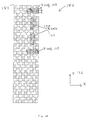
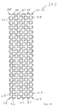
- Figures 1A and 1B are diagrammatic representations of plan views of embodiments of magnet-and-coil arrangements for use in a two-dimensional linear electric motor in accordance with the present invention.
- Figures 2A and 2B diagrammatically illustrate embodiments of arrays of magnetic poles for use in a two-dimensional linear electric motor in accordance with the present invention.
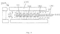
- Figure 3 is a diagrammatic representation of a section of an embodiment of a two-dimensional linear electric motor in accordance with the present invention.
- Figure 4 is a diagrammatic representation of a cross-sectional side view of an embodiment of a two-dimensional linear electric motor in accordance with the present invention.
- Figure 5A is a diagrammatic representation of a cross-sectional side view of a section of an embodiment of a two-dimensional linear electric motor in accordance with the present invention.
- Figure 5B is a diagrammatic representation of a cross-sectional side view of a magnet in a magnet array in an embodiment of a two-dimensional linear electric motor in accordance with the present invention.
- Figure 6 is a graph of a magnetic flux density B m versus a magnetic intensity H m within a two-dimensional motor in accordance with the present invention.
- Figures 7A and 7B diagrammatically illustrate a cross-sectional side view of an embodiment of a two-dimensional linear electric motor in accordance with the present invention.
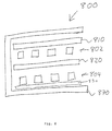
- Figure 8 diagrammatically illustrates a cross-sectional side view of an embodiment of a two-dimensional linear electric motor in accordance with the present invention.
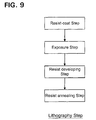
- Figure 9 shows an example of a flow chart of semiconductor fabrication method to which the apparatus of this invention can be applied easily.
- Figure 1A is a diagrammatic representation of a plan view of an embodiment of a magnet-and-coil arrangement 100 which is used in two-dimensional linear electric motors in accordance with the present invention.
- the magnet-and-coil arrangement 100 has a planar array 110 of permanent magnets, X coils 120 and 130, and Y coils 140 and 150.
- the embodiment 100 is only exemplary. Therefore, a distribution and number of permanent magnets need not be identical to the embodiment 110, and the number of X coils 120, 130 and Y coils 140, 150 depends upon the embodiment of the invention.
- the four coils shown are approximately equal in size. Therefore, for a given amount of electrical current flowing through them, the force the coils can exert in the X or Y direction is approximately equal.
- a single Y coil of twice the length would provide approximately as much force as either coil 140 or coil 150. However, the range the coil assembly could travel in the X direction without crossing the edges of the magnet array would be reduced. On the other hand, if less force is required for motion in the Y direction, a single, shorter Y coil 140 might be sufficient.
- the X and Y coils are held together to form a coil assembly 115.
- This coil assembly could then be attached to a stage or platform, whose position could then be controlled by the motor.
- a second array of permanent magnets may be placed to line up permanent magnets in the planar array 110 and have the X coils 120, 130 and the Y coils 140, 150 between the two planar magnetic arrays.
- a second array of permanent magnets may be placed to line up permanent magnets in the planar array 110 and have the X coils 120, 130 and the Y coils 140, 150 between the two planar magnetic arrays.
- each of the coils 120, 130, 140, and 150 have corresponding coils of the same size and shape on an opposite side of the array 110 of permanent magnets.
- the coils on both sides of the array 110 of permanent magnets are attached to each other such that they move together. This embodiment will be described in further detail below with reference to Figure 4.
- the array 110 of permanent magnets is planar in the embodiment in Figure 1A although it may have other shapes in other embodiments.
- the array 110 has both north and south poles, denoted by N and S, distributed in both longitudinal and latitudinal directions along a plane. Some embodiments, such as the embodiment 110, have the permanent magnets periodically distributed in the longitudinal and/or the latitudinal directions.
- Figure 1A depicts an embodiment with permanent magnets distributed in both directions.
- the embodiment in Figure 1A also shows an alternating pattern of north and south poles along diagonals of the array 110 and is rectangular in its distribution of north and south poles.
- the permanent magnets in the array 110 may have the same strength (the north and south poles having different polarities). The strength is proportional to the product of the magnetic flux density at the pole face and the area of the pole face.
- some embodiments have permanent magnets on the edges at one-half or three-quarters the strength of permanent magnets not on the boundary of the rectangular array 110.
- Some embodiments also have permanent magnets at corners of the rectangular array 110 with quarter-strength poles when compared with the strength of poles not on the boundary of the rectangular array 110.
- X coil 120 has a length 122 and a width 124 while X coil 130 has a length 132 and a width 134.
- a total length 126 of the X coils 120 and 130 determines how much travel the coils have in a Y direction 136. Since the combined length 126 is less than a length 112 of the array 110 of permanent magnets, the X coils 120 and 130 do not move past ends 114 and 116 of the array 110 of permanent magnets in some embodiments.
- the X coils 120 and 130 By restricting the X coils 120 and 130 to not move past the ends 114 and 116, the X coils 120 and 130 stay within the influence of the permanent magnets on the array 110. This restriction maintains a constant efficiency of the two-dimensional electric motor for motion in the X direction and minimizes an amount of magnetic fringing field, associated with the electrical currents in the coils, escaping from the motor.
- one of the Y coils would then extend beyond the array and be unable to provide force; the other Y coil remaining within the array 110 would provide all the available Y force.
- the total length 132 of the coil assembly 115 is less than the length of the array 112, it may be desired to limit travel in the Y direction, so that both Y coils remain within the array's boundaries at all times.
- the Y coils may be restricted to remain within the confines of the array 110 for motion in the X direction as well. This limits the motion of the coil assembly in the X direction to approximately a difference between a width of the magnet array 119 and a total length 145 of the Y coil assembly 140, assuming the length 145 to either be equal to or greater than an equivalent length 155 of the other Y coil assembly 150.
- the number of Y coils may vary, depending on the required amount of travel in the X direction and the amount of force required in the Y direction.
- a torque can be applied to the coil assembly 115 causing it to rotate.
- a total rotation angle is small, normal operation of the motor is unaffected.
- the Y coils this implies that a position of one end of a Y coil relative to a magnet should differ only slightly from an equivalent relative position at the other end of the coil for a magnet in the same row of the array.
- This feature permits fine rotational control of a stage or platform attached to the coil assembly 115.
- the order of the coils could be different, e.g., X, Y, Y, X or X, Y, X, Y, instead of Y, X, X, Y in Figure 1A.
- the X coils 120, 130 have multiple phases. Windings associated with the same phase are electrically connected to each other in some of the embodiments. The multiple phases of each X coil are drawn separated for clarity. However, their coil dimensions are ideally identical. Widths 124 and 134 are odd multiples of half of a unit latitudinal periodicity (pitch) 117 of the array 110. Lengths 122 and 132 are integer multiples of unit longitudinal periodicity 118 of the array 110. Windings 121A, 121B and 121C are overlapped to form a three-phase embodiment of the coil 120 as shown in Figure 1A.
- windings 121A, 121B and 121C are overlapped to form a three-phase embodiment of the X coil 130 depicted in Figure 1A.
- the embodiment of the Y coil 140 shown in Figure 1A is also a three-phase coil although the invention may have other numbers of phases. Windings 141A, 141B and 141C are combined or overlapped to form the three-phase embodiment of the Y coil 140. Y coil 150 is similarly constructed.
- the Y coils 140 and 150 have a length shorter than the width 119 of the magnet array 110. Similar to the case with the X coils, restricting motion of the Y coils in the X direction so that they do not move past ends 111 and 113 of the magnet array 110 maintains a constant efficiency for operation of the motor in the Y direction.
- a width 144 of Y coil 140 is an odd multiple of half of the array periodicity, or pitch 118.
- the length 142 of the Y coil 140 is an integer multiple of the pitch 117. This is true for each phase of the Y coil. Identical relations exist for Y coil 150.
- the X coils 120, 130 and Y coils 140, 150 each define areas that are large enough to overlap two or more permanent magnets in the array 110 of the same magnetic orientation.
- X coil 120 is large enough to cover two north poles or two south poles in some embodiments.
- movement of the coils becomes more stable, because deviations in magnet strength are averaged over more magnets. Also, since more magnetic flux is intercepted by the coil, the force generated by the motor will be greater for larger coils.
- the periodicity of the array and the arrangement of like poles along rows and columns oriented in the X and Y directions are properties of the array relevant to embodiments of the invention.
- the size of the magnets is limited only by these conditions.
- FIG. 1B An example of another embodiment of a magnet-and-coil arrangement 180 having a compact magnet array 182 is illustrated in Figure 1B.
- the coils 120, 130, 140, and 150 are the same as in the embodiment 100 in Figure 1A.
- the magnets in the compact magnet array 182 are almost touching along diagonal directions. If the magnet poles of opposite polarity get too close, some distortion of the magnetic fields might occur; instead of going to the corresponding magnet in the other array, some of the field lines might go to the nearest opposite polarity magnets in the same array. This would probably cause a slight weakening of the force when the coils are near the edges of the permanent magnets. Such a weakening could be corrected, if desired, by the control system.
- the coils can be considerably larger than the array pitch.
- the X-coil could have a width 134 of half the pitch 117 while the length 132 could be n units of pitch 118 where n is an integer.
- the integer n must be small enough to permit the desired travel range for a given magnet array size. From an inspection of Figure 1A, it should be clear that at least one phase of such a coil will cover on average n permanent magnets of one polarity and n permanent magnets of the opposite polarity.
- the fraction of the coil immersed in magnetic fields which can provide a net force if current is applied to the coil, will approach 2n/(4n+2), if the compact magnet array is used. As the integer n grows, this ratio approaches 0.5. This also means that up to half the power applied to the coil can contribute to generating a net force.
- the present motor should be capable of more efficient operation than conventional designs.
- Figure 2A is a diagrammatic representation of an embodiment 200 of the planar array of permanent magnets 110.
- all the interior permanent magnets have the same magnetic strength.
- North magnetic poles are indicated by N, and south magnetic poles are indicated by S.
- Edge permanent magnets which are not at corners such as permanent magnets 202, 204, 206, 208, 210, 212, 214, 216, 218 and 220, have half the strength of the interior permanent magnets.
- Corner permanent magnets, such as permanent magnets 222, 224, 226 and 228, have one-quarter strength of the interior permanent magnets.
- the relative strengths are indicated schematically by the number of arrows emanating from the north poles.
- FIG. 2B diagrammatically illustrates another embodiment 250 of the array of permanent magnets 110.
- interior permanent magnets in the embodiment 250 all have the same strength.
- permanent magnets on the edges such as permanent magnets 252, 254, 256, 258, 260, 262, 264, 266, 268 and 270, have one-half the strength of the permanent magnets in the interior of the embodiment 250.
- permanent magnets 272, 274, 276 and 278 have three-quarters the strength of magnets in the interior.
- the embodiments 200 and 250 both are designed to decrease fringe magnetic fields which would occur at the edges of the embodiments 200 and 250 if all the permanent magnets in the interior and on the edges were the same strength. This also ensures the motor properties do not change if the coils are close to an edge of an array.
- Such embodiments 200 and 250 may be designed by determining for each permanent magnet how many permanent magnets of opposite magnetic orientation are adjacent to the permanent magnet.
- Figure 3 is a diagrammatic representation of a cross-sectional side view of an embodiment of a two-dimensional electric motor 300 in accordance with the present invention.
- the embodiment 300 includes the magnet-and-coil arrangement 100 and a second planar array 310 of permanent magnets. Both planar arrays 110 and 310 of permanent magnets are attached to an enclosure 302, and each magnetic pole in the array 110 is aligned with an opposite polarity magnetic pole in the array 310 and vice versa.
- a two-dimensional armature 320 moves between the magnet arrays 110 and 310 and includes the X coils 120 and 130 and the Y coils 140 and 150.
- the array 110 is at a distance from the wall 304 which equals a distance which the array 310 is from the wall 306.
- the enclosure 302 contains a ferromagnetic material such as soft iron which will reduce fringe fields from the motor and increase the magnetic field between the arrays.
- the enclosure 302 may be a ferromagnetic material of high electrical resistivity, such as a ferrite, to reduce generation of eddy currents. The eddy currents might make precise control of the motor more difficult.
- Other embodiments of arrays 110 and 310 such as the embodiments 200 and 250 as shown in Figures 2A and 2B, may be substituted.
- FIG 4 is a diagrammatic representation of an embodiment of a two-dimensional linear electric motor 400 in accordance with the present invention.
- the embodiment 400 includes the magnet-and-coil arrangement 100 and has armature components 460 and 470.
- the armature component 470 includes the X coils 120 and 130 and the Y coils 140 and 150
- the armature component 460 includes X coils 420 and 430 and Y coils 440 and 450 which are substantially identical to coils 120, 130, 140 and 150, respectively.
- the planar array 110 of permanent magnets is placed between the armature assemblies 470 and 460 and is attached to an enclosure 402.
- the X coils 120 and 420 are aligned with each other as are the X coils 130 and 430, the Y coils 140 and 440, and the Y coils 150 and 450.
- the enclosure 402 contains a magnetically permeable material such as soft iron.
- the soft iron completes a magnetic circuit and provides a flux return path. This allows more of the magnetic flux to link the coils and contribute to the force when current flows in the coils. It also reduces fringe magnetic fields which could affect the performance of nearby magnetic field sensitive equipment.
- the number of coils in this embodiment can vary.
- all of the functions enumerated for this motor could be achieved using the two X coils 120 and 130 and one Y coil, either 440 or 450, or equivalent combinations.
- Figures 5A and 5B are diagrammatic representations of a section of the embodiment 400.
- the enclosure 402 alters the magnetic fields from the permanent magnets in the region of the armatures as can be understood from magnetostatic image theory.
- Permanent magnets 502 and 504 which are part of the array 110 of permanent magnets, in the presence of the enclosure 402, produce fields in regions of the armatures equivalent to that from magnets 502 and 504 plus a presence of "image" magnets 506, 508, 510 and 512 with the enclosure 402 removed.
- the separation between the inner edge of the enclosure 402 and the nearer pole face of the image magnets 506, 508, 510 and 512 is equal to the gap between the enclosure 402 and the magnet array 110.
- the embodiment 400 has a greater maximum force available than the embodiment 200 because it has dual sets of coils 120 and 420, 130 and 430, 140 and 440, and 150 and 450, in the armature components 470 and 460.
- This embodiment has the further advantage of using fewer magnets; with current technology, magnet arrays generally cost more than coils.
- a force for the embodiment 400 will generally be less than a factor of 2 greater than the embodiment 300. This is because a magnetic flux density within gaps separating the magnet array from the enclosures is less than that between corresponding magnets of the two arrays of embodiment 300. From magnetostatic image theory, the magnetic flux density within the gap is equivalent to that between two arrays of permanent magnets separated by twice the gap distance.
- l g ⁇ l m and the slope of the demagnetization curve is frequently small near typical intersection points. For example, for neodymium-iron-boron magnets, ⁇ / ⁇ 0 ⁇ 1.03 and B m0 ⁇ 1.2 W/m 2 . Then, if l g /l m ⁇ 0.25 initially, B g changes from 0.795B m0 to 0.66B m0 when the gap is doubled, a change of about 17%.
- the magnetic flux density is not much smaller in the embodiment 400 than that in the embodiment 300.
- greater forces in the embodiment 400 than in the embodiment 300 for the same number of turns of wire in the coils) are possible.
- only half as many permanent magnets are required in the embodiment 400.
- less current would flow in each set of coils than in the single set of embodiment 100. The lower current decreases coil heating.
- the magnetic flux density is no longer symmetric about the median plane of the gaps between the array 110 and the enclosure 402 occupied by the coil assemblies 470 and 460. Therefore the coils will experience vertical forces when excited.
- the magnetic flux density component providing the transverse force when a current flows in the coil is in the same direction, so if the current flows in the same direction in both coils, the forces on the two coils add.
- the B x component in the two gaps is in the opposite direction, so forces normal to the coil motion direction tend to cancel.
- vertical forces on the coil will in principle cancel out. There is generally no such cancellation possible in the single coil embodiment.
- FIG. 7A diagrammatically illustrates a cross-sectional side view of an embodiment 700 of a two-dimensional linear electric motor in accordance with the present invention.
- the embodiment 700 has arrays of permanent magnets 702 and 704.
- the permanent magnets in the array 702 have the same orientation as those in the array 704 to form closed magnetic flux circuits using magnetic poles of both arrays 702 and 704.
- Magnetic flux in magnetic circuits formed from magnets in arrays 702 and 704 flows in opposite directions in a ferromagnetic plate 770 separating the arrays 702 and 704. This largely cancels the magnetic field within the ferromagnetic plate 770, leading to low local flux densities.
- the ferromagnetic plate 770 is then less likely to become saturated, so its magnetic permeability will remain high. This may allow a thickness of the ferromagnetic plate 770 to be reduced, leading to a smaller, lighter motor.
- Coil assemblies 710 and 720 are on opposite sides of the array 702 of permanent magnets, and coil assemblies 730 and 740 are on opposite sides of the array 704 of permanent magnets.
- the array 702 and coil assemblies 710 and 720 form a submotor 750, and the array 704 and coil assemblies 730 and 740 form a submotor 760.
- the submotors 750 and 760 are separated by a ferromagnetic plate 770.
- a ferromagnetic plate 772 is on a second side of the submotor 750 while a ferromagnetic plate 774 is on a second side of the submotor 760.
- the ferromagnetic plates 770, 772 and 774 contain soft iron, or some other material with high magnetic permeability, in some embodiments.
- FIG. 8 diagrammatically illustrates a cross-sectional side view of another embodiment 800 of a two-dimensional linear electric motor in accordance with the present invention.
- the embodiment 800 has arrays of permanent magnets 802 and 804.
- Coil assemblies 810 and 830 lie between permanent magnet arrays 802 and 804 and a ferromagnetic enclosure 870, and a coil assembly 820 lies between permanent magnet arrays 802 and 804.
- the coil assemblies 810 and 820 are on opposite sides of the array 802 of permanent magnets while the coil assemblies 820 and 830 are on opposite sides of the array 804.
- the ferromagnetic enclosure 870 surrounds the arrays 802 and 804 and the coil assemblies 810, 820, and 830.
- the ferromagnetic enclosure 870 contains soft iron in some embodiments.
- This embodiment 800 has one fewer coil assembly, three, than the embodiment 700 in Figures 7A and 7B.
- the magnetic field in the gap between arrays 802 and 804 is somewhat larger than in the other 2 gaps, according to the description of Figure 6. Therefore, for equal sized coils and electrical currents, this embodiment should provide more than three-fourths the force provided by the embodiment of Figure 7A and 7B. Its smaller size and fewer coil assemblies may provide an advantage.
- the control system may be slightly more complicated.
- a semiconductor fabrication method comprises mainly wafer production step (or wafer preparation step), mask production (or mask preparation step), wafer processing step, assembly step and inspection step, each step comprising several substeps.
- wafer-processing step is a most important step to achieve the specified finest pattern width and registration limit.
- designed circuit patterns are stacked successively on the wafer and many operative semiconductor chips like memory devices or MPC are formed on the wafer.
- the wafer-processing step comprises the step of thin film formation step, wherein dielectric layer for insulation or metal layer for lead line and for electrode are formed, oxidization step to oxidize thin film or wafersubstrate, lithography step to form resist pattern to process the thin film or wafer substrate selectively, process step to etch the thin film or wafer substrate and to implant the ion or impurity into the thin film or wafer substrate using the resist pattern as a mask, resist stripping step to remove the resist from the wafer and chip inspection step. Wafer processing step is repeated many time necessary to make semiconductor chip be operable as designed.
- Fig. 9 shows a flow chart of lithography step which is a dominant step in the wafer processing step.
- the lithography step comprises resist-coat step wherein resist is coated on the wafer substrate with circuit element formed in a previous processing, exposure step to exposure the wafer coated with wafer, development step to develop the resist exposed in exposure step and anneal step to enhance durability of the resist pattern.
- the arrays of magnetic poles, coils, and coil assemblies can have either constant or varying curvature in one or two-dimensions as in cylindrical, and spherical arrangements of permanent magnets and coil assemblies.
- latitudinal and longitudinal directions may be defined, for example, in standard cylindrical with corresponding diagonal directions, and parallel arrays and coils lie on parallel surfaces. Accordingly, all such modifications are intended to be within the scope of the following claims.
Landscapes
- Physics & Mathematics (AREA)
- Engineering & Computer Science (AREA)
- General Physics & Mathematics (AREA)
- Chemical & Material Sciences (AREA)
- Combustion & Propulsion (AREA)
- Electromagnetism (AREA)
- Power Engineering (AREA)
- Linear Motors (AREA)
- Container, Conveyance, Adherence, Positioning, Of Wafer (AREA)
- Exposure Of Semiconductors, Excluding Electron Or Ion Beam Exposure (AREA)
- Exposure And Positioning Against Photoresist Photosensitive Materials (AREA)
- Magnetic Bearings And Hydrostatic Bearings (AREA)
Applications Claiming Priority (2)
| Application Number | Priority Date | Filing Date | Title |
|---|---|---|---|
| US09/247,450 US6127749A (en) | 1999-02-10 | 1999-02-10 | Two-dimensional electric motor |
| US247450 | 2000-02-10 |
Publications (2)
| Publication Number | Publication Date |
|---|---|
| EP1124310A2 true EP1124310A2 (de) | 2001-08-16 |
| EP1124310A3 EP1124310A3 (de) | 2002-04-10 |
Family
ID=22934991
Family Applications (1)
| Application Number | Title | Priority Date | Filing Date |
|---|---|---|---|
| EP00102790A Withdrawn EP1124310A3 (de) | 1999-02-10 | 2000-02-10 | Zweidimensionaler Elektromotor, Belichtungsapparat und Verfahren zur Herstellung eines Halbleiters |
Country Status (3)
| Country | Link |
|---|---|
| US (2) | US6127749A (de) |
| EP (1) | EP1124310A3 (de) |
| JP (1) | JP2000316270A (de) |
Families Citing this family (24)
| Publication number | Priority date | Publication date | Assignee | Title |
|---|---|---|---|---|
| US6127749A (en) * | 1999-02-10 | 2000-10-03 | Nikon Corporation Of Japan | Two-dimensional electric motor |
| TWI248718B (en) * | 1999-09-02 | 2006-02-01 | Koninkl Philips Electronics Nv | Displacement device |
| US6770987B1 (en) | 2000-07-25 | 2004-08-03 | Nikon Corporation | Brushless electric motors with reduced stray AC magnetic fields |
| US6570273B2 (en) * | 2001-01-08 | 2003-05-27 | Nikon Corporation | Electric linear motor |
| US6864601B2 (en) | 2001-03-01 | 2005-03-08 | Nikon Corporation | Electric motors with reduced stray magnetic fields |
| EP1465013B1 (de) * | 2003-03-11 | 2009-08-12 | ASML Netherlands B.V. | Lithographischer Apparat und Verfahren zur Herstellung eines Artikels |
| EP1457826A1 (de) * | 2003-03-11 | 2004-09-15 | ASML Netherlands B.V. | Lithographischer Apparat und Verfahren zur Herstellung eines Artikels |
| JP2007116815A (ja) * | 2005-10-19 | 2007-05-10 | Sumitomo Heavy Ind Ltd | リニアモータ |
| EP1780878A1 (de) * | 2005-10-25 | 2007-05-02 | Protronic N.V. | Kompakter Linear- und Drehmotor |
| US7348752B1 (en) * | 2006-09-20 | 2008-03-25 | Asml Netherlands B.V. | Stage apparatus and lithographic apparatus |
| CN101855811B (zh) * | 2007-06-27 | 2013-11-20 | 布鲁克斯自动化公司 | 具有提升能力和减少的齿槽特性的电机定子 |
| US9752615B2 (en) * | 2007-06-27 | 2017-09-05 | Brooks Automation, Inc. | Reduced-complexity self-bearing brushless DC motor |
| WO2009003186A1 (en) | 2007-06-27 | 2008-12-31 | Brooks Automation, Inc. | Multiple dimension position sensor |
| US7834618B2 (en) | 2007-06-27 | 2010-11-16 | Brooks Automation, Inc. | Position sensor system |
| US8283813B2 (en) | 2007-06-27 | 2012-10-09 | Brooks Automation, Inc. | Robot drive with magnetic spindle bearings |
| US8823294B2 (en) | 2007-06-27 | 2014-09-02 | Brooks Automation, Inc. | Commutation of an electromagnetic propulsion and guidance system |
| KR20180014247A (ko) | 2007-07-17 | 2018-02-07 | 브룩스 오토메이션 인코퍼레이티드 | 챔버 벽들에 일체화된 모터들을 갖는 기판 처리 장치 |
| CN101800460B (zh) * | 2009-12-23 | 2012-07-11 | 哈尔滨工业大学 | 集成绕组结构短行程直流平面电机 |
| NL2006714A (en) * | 2010-06-07 | 2011-12-08 | Asml Netherlands Bv | Displacement device, lithographic apparatus and positioning method. |
| CN102842974B (zh) * | 2012-08-03 | 2015-06-03 | 埃塞克科技有限公司 | 横向磁通发电机 |
| US10084364B2 (en) * | 2013-10-05 | 2018-09-25 | Nikon Research Corporation Of America | Power minimizing controller for a stage assembly |
| EP3152822B1 (de) * | 2014-06-07 | 2019-08-07 | The University Of British Columbia | Verfahren und systeme zur kontrollierten bewegung von mehrerer beweglicher stufen in einer verdrängervorrichtung |
| CN109991814B (zh) * | 2017-12-29 | 2020-07-21 | 广东极迅精密仪器有限公司 | 一种位移装置 |
| JP7786807B2 (ja) * | 2021-08-31 | 2025-12-16 | キヤノン株式会社 | 搬送装置、加工システム、制御方法及び物品の製造方法 |
Family Cites Families (88)
| Publication number | Priority date | Publication date | Assignee | Title |
|---|---|---|---|---|
| US34674A (en) * | 1862-03-18 | Improvement in boxes for car-axles | ||
| US3851196A (en) * | 1971-09-08 | 1974-11-26 | Xynetics Inc | Plural axis linear motor structure |
| US3789285A (en) * | 1972-03-27 | 1974-01-29 | Handotai Kenkyu Shinkokai | Position control system using magnetic force |
| DD134900A1 (de) * | 1978-02-28 | 1979-03-28 | Eberhard Riessland | Zweikoordinatenpositioniereinrichtung |
| JPS5568868A (en) * | 1978-11-14 | 1980-05-23 | Matsushita Electric Ind Co Ltd | Rectilinear-moving electric machine |
| JPS55106074A (en) * | 1979-02-02 | 1980-08-14 | Nec Corp | Moving-coil type linear motor |
| JPS5568869A (en) * | 1978-11-17 | 1980-05-23 | Sony Corp | Linear motor |
| JPS5568865A (en) * | 1978-11-20 | 1980-05-23 | Hitachi Ltd | Motor employing magnetic sensitive element |
| JPS55106070A (en) * | 1979-02-05 | 1980-08-14 | Matsushita Electric Ind Co Ltd | Motor |
| JPS55106072A (en) * | 1979-02-09 | 1980-08-14 | Toshiba Corp | Electromagnetic reciprocating machine |
| JPS564012A (en) * | 1979-06-23 | 1981-01-16 | Toyota Motor Corp | Pointer illuminating device |
| DE2945269A1 (de) * | 1979-11-09 | 1981-05-21 | Teldix Gmbh, 6900 Heidelberg | Positionierungseinrichtung fuer einen koerper |
| JPS56114014A (en) * | 1980-02-12 | 1981-09-08 | Omron Tateisi Electronics Co | Electrode-type level detector |
| JPS56114013A (en) * | 1980-02-13 | 1981-09-08 | Toshiba Corp | Control method of gas bag system |
| JPS57149745A (en) * | 1981-03-11 | 1982-09-16 | Tokyo Seimitsu Co Ltd | Selector for semiconductor element, etc. |
| JPS57149743A (en) * | 1981-03-11 | 1982-09-16 | Hitachi Ltd | Semiconductor device having pressure welding structure |
| JPS57149746A (en) * | 1981-03-12 | 1982-09-16 | Nec Kyushu Ltd | Tester for semiconductor substrate |
| JPS57165704A (en) * | 1981-04-03 | 1982-10-12 | Hitachi Ltd | Detecting system for light spot position |
| JPS57165703A (en) * | 1981-04-06 | 1982-10-12 | Olympus Optical Co Ltd | Measuring method for thickness of magnetic film |
| JPS5856912B2 (ja) * | 1981-04-06 | 1983-12-17 | 株式会社 マコメ研究所 | 2次元磁気スケ−ル装置 |
| IT1145094B (it) * | 1981-09-16 | 1986-11-05 | Martinson Srl | Lunetta autocentrante |
| JPS5856741A (ja) * | 1981-09-27 | 1983-04-04 | Nippon Telegr & Teleph Corp <Ntt> | ステ−ジの送り位置決め装置 |
| JPS5856740A (ja) * | 1981-09-28 | 1983-04-04 | Seiko Instr & Electronics Ltd | 磁気支持されたx−yテ−ブル |
| JPS5856744A (ja) | 1981-09-29 | 1983-04-04 | Matsushita Electric Ind Co Ltd | チヤツク |
| JPS58175021A (ja) * | 1982-04-05 | 1983-10-14 | Mitsubishi Electric Corp | サ−ボ装置 |
| JPS58175022A (ja) * | 1982-04-05 | 1983-10-14 | Mitsubishi Electric Corp | 同期運転制御装置 |
| JPS58173844A (ja) * | 1982-04-05 | 1983-10-12 | Nec Corp | 半導体装置 |
| JPS58175020A (ja) * | 1982-04-05 | 1983-10-14 | Telmec Co Ltd | 二次元精密位置決め装置 |
| JPS58173845A (ja) * | 1982-04-06 | 1983-10-12 | Citizen Watch Co Ltd | 半導体装置 |
| JPS58173843A (ja) * | 1982-04-07 | 1983-10-12 | Telmec Co Ltd | 平面駆動装置 |
| JPS5956888A (ja) * | 1982-09-22 | 1984-04-02 | Tokyo Erekutoron Kk | 二次元駆動装置 |
| JPS60234238A (ja) * | 1984-05-04 | 1985-11-20 | Mitsubishi Electric Corp | 焦点検出装置 |
| JPS60234240A (ja) * | 1984-05-07 | 1985-11-20 | Canon Inc | 対物レンズの駆動装置 |
| JPS60234239A (ja) * | 1984-05-07 | 1985-11-20 | Canon Inc | 対物レンズの2次元駆動装置および駆動方法 |
| JPS60261036A (ja) * | 1984-06-06 | 1985-12-24 | Toshiba Corp | トラツキングサ−ボシステムの信号切換回路 |
| JPS60261035A (ja) * | 1984-06-06 | 1985-12-24 | Matsushita Electric Ind Co Ltd | 光学式情報記録再生装置 |
| JPS60261037A (ja) * | 1984-06-07 | 1985-12-24 | Canon Inc | 対物レンズの2次元駆動装置 |
| JPS61126642A (ja) * | 1984-11-22 | 1986-06-14 | Seiko Epson Corp | 光ヘツド対物レンズアクチユエ−タ |
| JPS61126640A (ja) * | 1984-11-22 | 1986-06-14 | Canon Inc | 光学系駆動装置 |
| JPS61126641A (ja) * | 1984-11-22 | 1986-06-14 | Fuji Elelctrochem Co Ltd | 光学ヘツド |
| JPS61180942A (ja) * | 1985-01-11 | 1986-08-13 | Nippon Columbia Co Ltd | 光ピツクアツプ |
| JPS61180944A (ja) * | 1985-02-06 | 1986-08-13 | Nec Corp | 光デイスク装置の記録光量制御装置 |
| JPS61180943A (ja) * | 1985-02-06 | 1986-08-13 | Canon Inc | 光学系駆動装置 |
| JPS61258344A (ja) * | 1985-05-10 | 1986-11-15 | Mitsubishi Electric Corp | 情報処理装置 |
| JPS61258345A (ja) * | 1985-05-13 | 1986-11-15 | Toshiba Corp | 光ピツクアツプの対物レンズ支持駆動装置 |
| JP2611966B2 (ja) * | 1985-05-13 | 1997-05-21 | 株式会社東芝 | 対物レンズ駆動装置 |
| JPS6254838A (ja) * | 1985-09-03 | 1987-03-10 | Pioneer Electronic Corp | 光学式ピツクアツプ装置の対物レンズ用サスペンシヨンばねおよびその製造方法 |
| JPS6254839A (ja) * | 1985-09-03 | 1987-03-10 | Toshiba Corp | 3次元光ピツクアツプ |
| JPS6254840A (ja) * | 1985-09-04 | 1987-03-10 | Olympus Optical Co Ltd | 対物レンズ駆動装置 |
| US4654571A (en) * | 1985-09-16 | 1987-03-31 | Hinds Walter E | Single plane orthogonally movable drive system |
| JPS62100161A (ja) * | 1985-10-23 | 1987-05-09 | Shin Etsu Chem Co Ltd | 平面モ−タ |
| JPS62100162A (ja) * | 1985-10-24 | 1987-05-09 | Omron Tateisi Electronics Co | 平板状リニアパルスモ−タ |
| JPS62207164A (ja) * | 1986-03-05 | 1987-09-11 | Shikoo Giken:Kk | 周波数発電機内蔵直流モ−タ |
| JPS62207162A (ja) * | 1986-03-05 | 1987-09-11 | Ricoh Co Ltd | 多段モ−タ |
| JPS62207165A (ja) * | 1986-03-06 | 1987-09-11 | Omron Tateisi Electronics Co | 二次元アクチユエ−タ |
| JPS62100163A (ja) * | 1986-10-01 | 1987-05-09 | Hitachi Ltd | ゲ−トタ−ンオフサイリスタの保護装置 |
| US4839543A (en) | 1988-02-04 | 1989-06-13 | Trilogy Systems Corporation | Linear motor |
| JP2615840B2 (ja) * | 1988-05-17 | 1997-06-04 | カシオ計算機株式会社 | 指針式世界時計 |
| JPH01291195A (ja) * | 1988-05-18 | 1989-11-22 | Toshiba Corp | タンク型高速増殖炉 |
| JPH01291194A (ja) * | 1988-05-18 | 1989-11-22 | Tokyo Electron Ltd | X−yテーブル |
| JPH0679383B2 (ja) * | 1988-06-16 | 1994-10-05 | 株式会社三協精機製作所 | 対物レンズ駆動装置 |
| JPH01317236A (ja) * | 1988-06-15 | 1989-12-21 | Sony Corp | 半導体発光装置 |
| JPH01317235A (ja) * | 1988-06-17 | 1989-12-21 | Mitsubishi Electric Corp | 対物レンズ駆動装置 |
| JP2700330B2 (ja) * | 1988-08-17 | 1998-01-21 | キヤノン株式会社 | ブラシレスモータ |
| JPH0255564A (ja) * | 1988-08-17 | 1990-02-23 | Canon Inc | ステッピングモータ |
| JPH0255566A (ja) * | 1988-08-19 | 1990-02-23 | Canon Electron Inc | パルスモータ |
| JP3013997B2 (ja) * | 1989-12-06 | 2000-02-28 | 住友重機械工業株式会社 | 2次元モータ式ステージ装置 |
| JPH03178746A (ja) * | 1989-12-06 | 1991-08-02 | Sumitomo Heavy Ind Ltd | 二次元可動ステージ装置 |
| JPH03178744A (ja) * | 1989-12-07 | 1991-08-02 | Kosumetsuku:Kk | クランプ具傾斜直動形油圧クランプ |
| JPH04112306A (ja) * | 1990-09-03 | 1992-04-14 | Fanuc Ltd | 速度ループ積分制御方式 |
| JPH07101371B2 (ja) * | 1990-09-03 | 1995-11-01 | 工業技術院長 | 被駆動体の制御装置 |
| JPH04112304A (ja) * | 1990-09-03 | 1992-04-14 | Fanuc Ltd | I/oモジュールのチェック方式 |
| JP3178746B2 (ja) | 1991-09-25 | 2001-06-25 | 松下電器産業株式会社 | 浮動小数点数のためのフォーマット変換装置 |
| JP2560949B2 (ja) * | 1992-04-22 | 1996-12-04 | 豊田合成株式会社 | 防振装置の振動体取付構造 |
| JP3104399B2 (ja) * | 1992-04-22 | 2000-10-30 | 豊田合成株式会社 | 防振装置 |
| JPH05296286A (ja) * | 1992-04-22 | 1993-11-09 | Fuji Elelctrochem Co Ltd | 磁気ダンパ装置 |
| JP3299308B2 (ja) * | 1992-07-02 | 2002-07-08 | ジーイー横河メディカルシステム株式会社 | 勾配磁場用コイル単位、勾配磁場コイル及びmri装置 |
| JP3178744B2 (ja) | 1992-09-08 | 2001-06-25 | 宇宙開発事業団 | 衛星搭載用アレーアンテナ |
| JP3178747B2 (ja) | 1992-10-30 | 2001-06-25 | キヤノン株式会社 | 視線検出装置 |
| JP3265665B2 (ja) * | 1993-01-07 | 2002-03-11 | 株式会社ニコン | 投影露光装置、露光方法、及び素子製造方法 |
| JPH0748028A (ja) * | 1993-08-06 | 1995-02-21 | Daifuku Co Ltd | 直流リニアモータ利用の移動設備 |
| JPH0760581A (ja) * | 1993-08-31 | 1995-03-07 | Shimadzu Corp | X−yステージ |
| JPH07131966A (ja) * | 1993-11-05 | 1995-05-19 | Sharp Corp | 2次元リニアモータ |
| JP3695542B2 (ja) * | 1994-02-23 | 2005-09-14 | 日本トムソン株式会社 | リニア電磁アクチュエータを具備したxy駆動装置 |
| JPH07262581A (ja) * | 1994-03-24 | 1995-10-13 | Toshiba Corp | 対物レンズ駆動装置 |
| JPH09182410A (ja) * | 1995-12-20 | 1997-07-11 | Minolta Co Ltd | リニアモータ |
| US5886432A (en) * | 1997-04-28 | 1999-03-23 | Ultratech Stepper, Inc. | Magnetically-positioned X-Y stage having six-degrees of freedom |
| US6127749A (en) * | 1999-02-10 | 2000-10-03 | Nikon Corporation Of Japan | Two-dimensional electric motor |
-
1999
- 1999-02-10 US US09/247,450 patent/US6127749A/en not_active Expired - Fee Related
-
2000
- 2000-02-10 JP JP2000033984A patent/JP2000316270A/ja active Pending
- 2000-02-10 EP EP00102790A patent/EP1124310A3/de not_active Withdrawn
- 2000-07-31 US US09/629,792 patent/US6455956B1/en not_active Expired - Fee Related
Also Published As
| Publication number | Publication date |
|---|---|
| US6455956B1 (en) | 2002-09-24 |
| EP1124310A3 (de) | 2002-04-10 |
| US6127749A (en) | 2000-10-03 |
| JP2000316270A (ja) | 2000-11-14 |
Similar Documents
| Publication | Publication Date | Title |
|---|---|---|
| US6455956B1 (en) | Two-dimensional electric motor | |
| US6188147B1 (en) | Wedge and transverse magnet arrays | |
| JP4562336B2 (ja) | 変位装置 | |
| US6316849B1 (en) | Methods and apparatus involving selectively tailored electromagnetic fields | |
| US6791214B2 (en) | Moving-magnet linear motor, aligner and apparatus provided therewith, and method for manufacturing devices using the same | |
| US6107703A (en) | Linear motor mechanism for exposure apparatus, and device manufacturing method using the same | |
| US6208045B1 (en) | Electric motors and positioning devices having moving magnet arrays and six degrees of freedom | |
| EP0131155B1 (de) | Elektromagnetische Ausrichtvorrichtung | |
| US7291953B1 (en) | High performance motor and magnet assembly therefor | |
| JP3215362B2 (ja) | リニアモータ、ステージ装置および露光装置 | |
| KR20020079961A (ko) | 상호 위치를 검출하는 두 부분 변위 장치 | |
| US6770987B1 (en) | Brushless electric motors with reduced stray AC magnetic fields | |
| JPWO1999053600A1 (ja) | 多角形のコイルユニットを有するリニアモーター | |
| TW201021369A (en) | Planar motor with wedge shaped magnets and diagonal magnetization directions | |
| JP2002325421A (ja) | リニアモータ、およびこれを用いたステージ装置、露光装置ならびにデバイス製造方法 | |
| EP1292968B1 (de) | Bewegungsvorrichtung | |
| US7362013B2 (en) | Linear motor, exposure apparatus using the same, and device manufacturing method | |
| US6876108B2 (en) | Linear motor, its controlling method, and XY table | |
| KR20090114458A (ko) | 평면 모터, 위치 결정 장치, 노광 장치 및 디바이스 제조 방법 | |
| CN115603542A (zh) | 洛伦兹电机及磁场优化方法 | |
| JP2001284239A (ja) | 荷電粒子線露光装置、及び半導体デバイスの製造方法 | |
| JPH1140978A (ja) | 磁気回路の漏れ磁界低減方法及びその低減方法を用いた電磁アクチュエータ | |
| JP3700883B2 (ja) | リニアモータの固定子 | |
| JP3793874B2 (ja) | 永久磁石形リニアモータ | |
| JP4137091B2 (ja) | ステージ装置およびリニアモータ、ならびに前記ステージ装置を用いた露光装置およびデバイス製造方法 |
Legal Events
| Date | Code | Title | Description |
|---|---|---|---|
| PUAI | Public reference made under article 153(3) epc to a published international application that has entered the european phase |
Free format text: ORIGINAL CODE: 0009012 |
|
| AK | Designated contracting states |
Kind code of ref document: A2 Designated state(s): AT BE CH CY DE DK ES FI FR GB GR IE IT LI LU MC NL PT SE |
|
| AX | Request for extension of the european patent |
Free format text: AL;LT;LV;MK;RO;SI |
|
| PUAL | Search report despatched |
Free format text: ORIGINAL CODE: 0009013 |
|
| AK | Designated contracting states |
Kind code of ref document: A3 Designated state(s): AT BE CH CY DE DK ES FI FR GB GR IE IT LI LU MC NL PT SE |
|
| AX | Request for extension of the european patent |
Free format text: AL;LT;LV;MK;RO;SI |
|
| AKX | Designation fees paid | ||
| REG | Reference to a national code |
Ref country code: DE Ref legal event code: 8566 |
|
| STAA | Information on the status of an ep patent application or granted ep patent |
Free format text: STATUS: THE APPLICATION IS DEEMED TO BE WITHDRAWN |
|
| 18D | Application deemed to be withdrawn |
Effective date: 20021011 |