EP0971140A1 - Linearführungseinrichtung mit Schmierungssystem - Google Patents
Linearführungseinrichtung mit Schmierungssystem Download PDFInfo
- Publication number
- EP0971140A1 EP0971140A1 EP99112952A EP99112952A EP0971140A1 EP 0971140 A1 EP0971140 A1 EP 0971140A1 EP 99112952 A EP99112952 A EP 99112952A EP 99112952 A EP99112952 A EP 99112952A EP 0971140 A1 EP0971140 A1 EP 0971140A1
- Authority
- EP
- European Patent Office
- Prior art keywords
- lubricant
- linear guide
- lubricating oil
- guide device
- carriage
- Prior art date
- Legal status (The legal status is an assumption and is not a legal conclusion. Google has not performed a legal analysis and makes no representation as to the accuracy of the status listed.)
- Granted
Links
Images


Classifications
-
- F—MECHANICAL ENGINEERING; LIGHTING; HEATING; WEAPONS; BLASTING
- F16—ENGINEERING ELEMENTS AND UNITS; GENERAL MEASURES FOR PRODUCING AND MAINTAINING EFFECTIVE FUNCTIONING OF MACHINES OR INSTALLATIONS; THERMAL INSULATION IN GENERAL
- F16C—SHAFTS; FLEXIBLE SHAFTS; ELEMENTS OR CRANKSHAFT MECHANISMS; ROTARY BODIES OTHER THAN GEARING ELEMENTS; BEARINGS
- F16C29/00—Bearings for parts moving only linearly
- F16C29/04—Ball or roller bearings
- F16C29/06—Ball or roller bearings in which the rolling bodies circulate partly without carrying load
- F16C29/0633—Ball or roller bearings in which the rolling bodies circulate partly without carrying load with a bearing body defining a U-shaped carriage, i.e. surrounding a guide rail or track on three sides
- F16C29/0635—Ball or roller bearings in which the rolling bodies circulate partly without carrying load with a bearing body defining a U-shaped carriage, i.e. surrounding a guide rail or track on three sides whereby the return paths are provided as bores in a main body of the U-shaped carriage, e.g. the main body of the U-shaped carriage is a single part with end caps provided at each end
- F16C29/0638—Ball or roller bearings in which the rolling bodies circulate partly without carrying load with a bearing body defining a U-shaped carriage, i.e. surrounding a guide rail or track on three sides whereby the return paths are provided as bores in a main body of the U-shaped carriage, e.g. the main body of the U-shaped carriage is a single part with end caps provided at each end with balls
- F16C29/0642—Ball or roller bearings in which the rolling bodies circulate partly without carrying load with a bearing body defining a U-shaped carriage, i.e. surrounding a guide rail or track on three sides whereby the return paths are provided as bores in a main body of the U-shaped carriage, e.g. the main body of the U-shaped carriage is a single part with end caps provided at each end with balls with four rows of balls
- F16C29/0645—Ball or roller bearings in which the rolling bodies circulate partly without carrying load with a bearing body defining a U-shaped carriage, i.e. surrounding a guide rail or track on three sides whereby the return paths are provided as bores in a main body of the U-shaped carriage, e.g. the main body of the U-shaped carriage is a single part with end caps provided at each end with balls with four rows of balls with load directions in O-arrangement
-
- F—MECHANICAL ENGINEERING; LIGHTING; HEATING; WEAPONS; BLASTING
- F16—ENGINEERING ELEMENTS AND UNITS; GENERAL MEASURES FOR PRODUCING AND MAINTAINING EFFECTIVE FUNCTIONING OF MACHINES OR INSTALLATIONS; THERMAL INSULATION IN GENERAL
- F16C—SHAFTS; FLEXIBLE SHAFTS; ELEMENTS OR CRANKSHAFT MECHANISMS; ROTARY BODIES OTHER THAN GEARING ELEMENTS; BEARINGS
- F16C29/00—Bearings for parts moving only linearly
- F16C29/04—Ball or roller bearings
- F16C29/06—Ball or roller bearings in which the rolling bodies circulate partly without carrying load
- F16C29/0602—Details of the bearing body or carriage or parts thereof, e.g. methods for manufacturing or assembly
- F16C29/0604—Details of the bearing body or carriage or parts thereof, e.g. methods for manufacturing or assembly of the load bearing section
- F16C29/0607—Details of the bearing body or carriage or parts thereof, e.g. methods for manufacturing or assembly of the load bearing section of parts or members for retaining the rolling elements, i.e. members to prevent the rolling elements from falling out of the bearing body or carriage
-
- F—MECHANICAL ENGINEERING; LIGHTING; HEATING; WEAPONS; BLASTING
- F16—ENGINEERING ELEMENTS AND UNITS; GENERAL MEASURES FOR PRODUCING AND MAINTAINING EFFECTIVE FUNCTIONING OF MACHINES OR INSTALLATIONS; THERMAL INSULATION IN GENERAL
- F16C—SHAFTS; FLEXIBLE SHAFTS; ELEMENTS OR CRANKSHAFT MECHANISMS; ROTARY BODIES OTHER THAN GEARING ELEMENTS; BEARINGS
- F16C29/00—Bearings for parts moving only linearly
- F16C29/04—Ball or roller bearings
- F16C29/06—Ball or roller bearings in which the rolling bodies circulate partly without carrying load
- F16C29/0602—Details of the bearing body or carriage or parts thereof, e.g. methods for manufacturing or assembly
- F16C29/0609—Details of the bearing body or carriage or parts thereof, e.g. methods for manufacturing or assembly of the ends of the bearing body or carriage where the rolling elements change direction, e.g. end caps
-
- F—MECHANICAL ENGINEERING; LIGHTING; HEATING; WEAPONS; BLASTING
- F16—ENGINEERING ELEMENTS AND UNITS; GENERAL MEASURES FOR PRODUCING AND MAINTAINING EFFECTIVE FUNCTIONING OF MACHINES OR INSTALLATIONS; THERMAL INSULATION IN GENERAL
- F16C—SHAFTS; FLEXIBLE SHAFTS; ELEMENTS OR CRANKSHAFT MECHANISMS; ROTARY BODIES OTHER THAN GEARING ELEMENTS; BEARINGS
- F16C29/00—Bearings for parts moving only linearly
- F16C29/04—Ball or roller bearings
- F16C29/06—Ball or roller bearings in which the rolling bodies circulate partly without carrying load
- F16C29/0602—Details of the bearing body or carriage or parts thereof, e.g. methods for manufacturing or assembly
- F16C29/0611—Details of the bearing body or carriage or parts thereof, e.g. methods for manufacturing or assembly of the return passages, i.e. the passages where the rolling elements do not carry load
-
- F—MECHANICAL ENGINEERING; LIGHTING; HEATING; WEAPONS; BLASTING
- F16—ENGINEERING ELEMENTS AND UNITS; GENERAL MEASURES FOR PRODUCING AND MAINTAINING EFFECTIVE FUNCTIONING OF MACHINES OR INSTALLATIONS; THERMAL INSULATION IN GENERAL
- F16C—SHAFTS; FLEXIBLE SHAFTS; ELEMENTS OR CRANKSHAFT MECHANISMS; ROTARY BODIES OTHER THAN GEARING ELEMENTS; BEARINGS
- F16C33/00—Parts of bearings; Special methods for making bearings or parts thereof
- F16C33/30—Parts of ball or roller bearings
- F16C33/66—Special parts or details in view of lubrication
- F16C33/6603—Special parts or details in view of lubrication with grease as lubricant
- F16C33/6622—Details of supply and/or removal of the grease, e.g. purging grease
-
- F—MECHANICAL ENGINEERING; LIGHTING; HEATING; WEAPONS; BLASTING
- F16—ENGINEERING ELEMENTS AND UNITS; GENERAL MEASURES FOR PRODUCING AND MAINTAINING EFFECTIVE FUNCTIONING OF MACHINES OR INSTALLATIONS; THERMAL INSULATION IN GENERAL
- F16C—SHAFTS; FLEXIBLE SHAFTS; ELEMENTS OR CRANKSHAFT MECHANISMS; ROTARY BODIES OTHER THAN GEARING ELEMENTS; BEARINGS
- F16C33/00—Parts of bearings; Special methods for making bearings or parts thereof
- F16C33/30—Parts of ball or roller bearings
- F16C33/66—Special parts or details in view of lubrication
- F16C33/6637—Special parts or details in view of lubrication with liquid lubricant
- F16C33/6659—Details of supply of the liquid to the bearing, e.g. passages or nozzles
-
- F—MECHANICAL ENGINEERING; LIGHTING; HEATING; WEAPONS; BLASTING
- F16—ENGINEERING ELEMENTS AND UNITS; GENERAL MEASURES FOR PRODUCING AND MAINTAINING EFFECTIVE FUNCTIONING OF MACHINES OR INSTALLATIONS; THERMAL INSULATION IN GENERAL
- F16C—SHAFTS; FLEXIBLE SHAFTS; ELEMENTS OR CRANKSHAFT MECHANISMS; ROTARY BODIES OTHER THAN GEARING ELEMENTS; BEARINGS
- F16C33/00—Parts of bearings; Special methods for making bearings or parts thereof
- F16C33/30—Parts of ball or roller bearings
- F16C33/66—Special parts or details in view of lubrication
- F16C33/6637—Special parts or details in view of lubrication with liquid lubricant
- F16C33/6681—Details of distribution or circulation inside the bearing, e.g. grooves on the cage or passages in the rolling elements
Definitions
- the invention relates to a linear guide device comprising a Guide rail with a longitudinal axis, at least one guide carriage, which is using on the guide rail at least a rolling element loop rotating in a circulation space of the guide carriage is guided in the direction of the longitudinal axis, this rolling element loop a supporting row of rolling elements in simultaneous engagement with a supporting track of the guide rail and with a supporting one career of the carriage, also a returning row of rolling elements as well as two deflection bend rolling element rows, the further Carriage of a main body in the length range of the load-bearing rolling element row and of head piece units on the axial spaced ends of the carriage main body is formed, further Deflection guides for the deflection bend rolling element rows at least are partially formed on these head piece units, with further Lubricant is required on at least part of the rolling surfaces and a lubricant path system to meet this lubricant need is provided in the carriage, which by a Lubricant supply area of the carriage leads to rolling surfaces, and wherein this lubricant path system
- the lubricant path system includes in its end region near the rolling elements one each Lubricant channel within a radially inner deflection piece Deflection guide. This lubricant channel opens into a deflection surface of the deflection piece and thus into the circulation space of the rolling elements.
- the mouth is in the radially inner Deflecting lubricant channel in the form of a throttle valve a closely calibrated bore formed by the lubricant channel in the radial direction to the radially inner deflection surface of the deflection piece leads.
- the outflow of lubricating oil takes place in the Circulation space of the rolling elements through outflow channels of the radially inner Deflection body, which in the radially inner deflection surface of the deflection body flow out.
- the outflow channels assume a common one Throttle chamber, which receives a foam strip.
- Throttle chamber which receives a foam strip.
- the oil penetrates the open cell Foam that acts as a choke.
- the foam is not in Contact with the rolling elements.
- the lubricating oil must rather be Penetration of the foam as a result of a pressure pulse Flow outflow channels from the throttle chamber into the circulation space.
- the foam strip prevents oil from escaping into the circulation space when there is no pressure pulse.
- the invention is based on the technical problem when in use of lubricating oil as a lubricant to ensure that in the circulation space sufficient lubricating oil is always available in the long term, at the same time but also to ensure that no lubricating oil quantities above the respective Lubrication needs get into and out of the circulation space then possibly can exit.
- the invention proposes that one connected to the lubricant supply space and at least partly in the border area approximately in the circumferential direction of the Lubricating oil supply line running at least on the guide rail part of their length from a pressure-dependent accelerating Lubricating oil supply capillary line is formed, which in at least one Leak area in litter contact with rolling elements of at least one Rolling body loop or with the load-bearing track of the guide rail stands.
- the lubricant supply space can be in the form of a or be formed of several chambers, but can also be easily from one be formed upstream part of the lubricant path system. It there should also be no restriction regarding the type of lubricant filling and refill exist. It is conceivable that one periodically Lubricating oil, for example, through a lubrication nipple designed as a check valve enters the lubricant supply room. It is also conceivable that one with the manufacturer or with the user before starting to use a lifetime fill in the lubricant supply room enters.
- the rolling elements lick it Lubricating oil from the lubricating oil supply capillary in the respective leak area when the rolling elements roll at this leak area move past.
- the lubricating oil from the lubricating oil supply capillary in the respective lick area through the career of Guide rail licked when the guide carriage runs along the guide rail moves.
- lubricating oil can become too Rolling elements or the track of the guide rail always and only then arrive when there is a relative movement between the licking area the lubricating oil supply capillary on the one hand and the rolling elements or the supporting career of the guide rail on the other hand.
- the lubricating oil supply capillary is either due to its large volume soaked in lubricating oil or due to their communication with free lubricating oil in the lubricant supply room suitable, the lubricating oil wetting of the rolling elements or the load-bearing Long-term career of the guide rail in accordance with the Ensure need.
- Parameters such as permeability of the lubricating oil supply capillary line, cross section this capillary line, viscosity of the lubricating oil and size of the Contact area of the capillary with the rolling elements or the load-bearing
- the lubricating oil supply according to the invention is subject to one Self-regulation, as with lubricating oil depletion in the area near the rolling elements the lubricating oil supply capillary line by intensive licking off Lubricating oil the saturation gradient in the lubricating oil supply capillary becomes larger and, accordingly, the lubricating oil production increases becomes.
- This self-regulation effect is also supported by that when there is little oil on the surface of the rolling elements or track-side career a greater adhesive effect in the sense of a Larger oil consumption from the spill area of the capillary entry.
- the length of the lubricating oil supply capillary is basically none Subject to restrictions. Wherever part of the lubricating oil supply capillary is nearby, with appropriate dimensioning the absorbency and avoidance or keeping small of not using Lubricant pockets filled with capillary material with suction, for example free lubricating oil quantities occurring are calculated, so that the Problem of sealing in the border area between the head unit and Main body is switched off or largely defused.
- the lubricating oil supply capillary line can be made of an absorbent textile material, such as felt. It can also come from one open-cell or open-pore, absorbent material. Open-cell foam, in particular made of a polymer plastic, comes into question here in particular. With these materials, the lubricating oil is transported by capillary action in the capillaries or pores of the respective material, regardless of whether from the outside Pressure drop is applied or not. Such a pressure drop can possibly the lubricating oil transport in the lubricating oil supply capillary favor, but is not decisive for this.
- Lubricant path system next to that of the lubricating oil supply capillary oil absorbed contains an additional amount of free oil, which forms an oil reservoir in the lubricant path system, removes the Lubricating oil supply capillary line this oil supply to the same extent as oil it releases such at its licking area, so that the degree of saturation the lubricating oil supply capillary line does not decrease and a declining one Relubrication of the rolling surfaces should not be feared.
- a sintered metal As an alternative material to form the lubricating oil supply capillary a sintered metal has proven to be, for example sintered bronze. Sintered metals are characterized by high wear resistance, which is why they can be used to form treads which the rolling elements of the rolling element loops in the circulation space run along.
- the guide carriage can be essentially U-shaped with a web area, which is adjacent to a head surface of the guide rail, and with Leg areas, which each have a side surface of the guide rail are adjacent, the supporting row of rolling elements at least one each Rolling body loop between one leg area and one each Side surface of the guide rail is arranged and the lubricating oil supply line correspondingly U-shaped over the web area and the leg areas runs.
- the lubricating oil supply capillary line can then extend at least approximately over the length of the leg region, if desired also at least over part of the web area.
- the lubricating oil supply capillary line can be substantially U-shaped be formed and from the load-bearing row of rolling elements at least one rolling element loop of one leg area to the bearing rolling element row of the at least one rolling element loop of the extend other leg area.
- a single lubricating oil supply capillary can thus supply several rolling elements simultaneously can be achieved with oil, specifically such rolling element grinding, those in different thigh areas of the carriage are accommodated.
- By the length of the lubricating oil supply capillary can then have a certain storage capacity for the capillary Result in lubricating oil. This storage capacity is preferred to larger ones Periods and correspondingly long operating phases without refill-related Interruptions.
- the lubricant supply space is expedient for reasons of space arranged in the web area of the U-shaped guide carriage, especially in the web area of at least one head piece unit. Moreover enables this accommodation of the lubricant supply room same cable lengths to the in different leg areas of the Rolling body loops housed in the carriage.
- the licking area also be comparatively large-scale without further ado, what the even oil supply to all rolling elements improved.
- the lubricating oil supply capillary with its licking area in the circulation space of the Protruding rolling element grinds a little like a nose.
- the lubricant path system can be at least partially in an intermediate plate unit be housed, which between an axial End of the carriage main body and the associated head unit is arranged. It is recommended that the intermediate plate unit at least in part made of oil-tight material, in particular Plastic. For sealing the in the intermediate plate unit parts of the lubricant path system, it is advisable to if the intermediate plate unit on the carriage main body and / or on the head piece unit is tight against oil.
- the intermediate plate unit can have at least one recess have partial intake of the lubricating oil supply capillary. If the recess is at least part of its circumferential direction the length of the guide rail from the lubricating oil supply capillary is essentially fully completed free oil flow leading to undesirable leakage of Lubricating oil could result in the recess excluded.
- the recess is preferably in relief in the intermediate plate unit trained and is exposed to the main body of the car. The connection of the Recess with the preferably housed in the head piece Lubricant supply room can then be easily created be that the recess has connecting openings.
- the deflecting surface having deflecting body integral on the intermediate plate unit be molded on.
- the intermediate plate unit is preferably used as a molded plastic part manufactured in an injection molding process. To meet the high demands on the guidance accuracy of the deflection surfaces can also be a comparatively hard for the intermediate plate unit Plastic are used. If the recess on the to Carriage main body facing side of the intermediate plate unit in this is formed, the inner deflection surface is expedient on the side of the Intermediate plate unit be molded.
- the Lubricant path system next to the lubricating oil supply capillary Grease supply line from the common lubricant supply room to at least one separate from the spill area Grease mouth structure includes, on which the grease supply line in the circulation space or in the track of the guide rail flows into. It is possible that the grease supply line and the lubricating oil supply capillary line over at least part of its length run parallel to each other, with the lubricating oil supply capillary at least part of the cross-sectional limitation of the grease supply line forms.
- the cross-sectional limitation the grease supply line at least partially from the Lubricating oil supply capillary line is formed, because then an absorption of the unbound lubricating oil from the grease supply line into the Lubricating oil supply capillary line is possible.
- This suction effect can be reinforced if the grease supply line at least part of its length in a slot of the lubricating oil supply capillary runs.
- the grease supply line can also be in a relief-like recess of the lubricating oil supply capillary line or be completely enclosed by it.
- the lubricating oil supply capillary line can be at least partially in one Intermediate plate unit can be housed, which in the area of a deflection roller row forms a deflector inside the bow, being connected to one of the lubricating oil supply capillary at least partially limited line section of the grease supply line these within the deflection body up to at least one Grease muzzle structure is continued.
- the deflector is common to a plurality of rolling element loops, it is recommended that the grease supply line within the deflecting body to several Rolling body grinding is branched out. It is particularly favorable if the deflecting body between two adjacent deflecting surfaces a grease orifice structure for adjacent rolling element loops owns. The grease supply line will then only branch shortly before the rolling element loops to be supplied, which is almost identical Lubrication conditions guaranteed on the rolling element loops.
- the shut-off point of the grease supply line already mentioned is located preferably upstream of the grease orifice structure. At the Grease orifice structure itself then needs another throttle or Blocking point should not be provided because of the grease its high viscosity anyway not uncontrolled to the circulation space or can escape to the track of the guide rail.
- the Relocation of the grease shut-off point to an upstream location the structure of the lubricating grease mouth proves to be advantageous. If the shut-off point is no longer directly at the outflow to the Circulation space or to the track of the guide rail, so can to find the cheapest place to locate the barrier choose to make the barrier simple and tight.
- Lubricant input connections that can be used optionally for lubricant input it is appropriate that individual or groups of such lubricant input connections one valve element is assigned and that these valve elements are so independent of each other that when applied a predetermined lubricant input pressure at one of the Lubricant inlet connections only the associated valve element opens. This measure makes the individual lubricant inlet connections decoupled from each other. When filling with lubricant At one of the lubricant inlet connections, the immediate re-emergence of lubricant just refilled at the other lubricant inlet connections prevents these other lubricant input connections assigned valve elements remain closed.
- the other lubricant inlet connections then do not have to be included Blind plugs are closed, which has a cost-saving effect.
- the Valve elements are preferably within a head unit and / or attached to an intermediate plate unit, which is between the head unit and the main body of the car.
- the particular in the form of check valves trained valve elements can from the respective material of the head piece unit or the intermediate plate unit be formed, preferably in one piece with the head unit or the intermediate plate unit.
- lubricant input means are on the guide carriage arranged which to the lubricant supply room are connected, so that a refill of the lubricant path system is possible. Because of the different properties of grease and lubricating oil are not critical in the area of lubricant input, For space and price reasons, it is recommended that the lubricant supply room through a common lubricant input can be loaded with lubricating oil or grease.
- the lubricant input means on a plastic part in particular are attached to a head unit of the carriage.
- the lubricant input means a A plurality of lubricant input ports include and that the plastic part a reinforcing part, in particular made of metallic Material is attached, which connection components for the Lubricant input ports carries.
- the resistant material of the Armoring actuator prevents damage to the lubricant inlet connections, caused by improper screwing in of a grease nipple or by improperly connecting a lubricant filling device could arise.
- connection components are designed as internal threaded bushings, which with one connection hole each of the lubricant inlet connections in Stand cover.
- a grease nipple to refill Lubricant can be screwed in while in the female studs the other lubricant inlet connections, if necessary, a closure, for example made of plastic, can be used.
- the invention in another view, relates to a linear guide device, comprising a guide rail with a longitudinal axis, at least one carriage, which is on the guide rail using at least one in a circulation space of the Carriage guided roller body loop in the direction of the longitudinal axis is guided, this rolling element loop a load-bearing rolling element row in simultaneous engagement with a supporting career of Guide rail and with a load-bearing track of the guide carriage, also a returning row of rolling elements and two rows of deflection bends has, with lubricant requirement at least part of the rolling surfaces and to satisfy this lubricant requirement a lubricant path system is provided in the carriage which is from a lubricant supply room of the guide carriage leads to rolling surfaces, this linear guide device especially designed in the manner described above is.
- a lubricating oil supply line and a grease supply line are connected that the lubricating oil supply line to at least part of their length from a pressure-dependent accelerating Lubricating oil supply capillary line is formed, which in at least one Leak area in litter contact with rolling elements of at least one Rolling body loop or with the load-bearing track of the guide rail stands that the grease supply line on at least one grease orifice structure in the circulation space or the supporting career of the Guide rail opens and that in the grease supply line a shut-off device upstream of the grease orifice structure is provided, which can be opened by grease pressure.
- the lubricating oil supply capillary preferably takes at least one essential part of the length of the lubricating oil supply line between the Lubricant supply room and the leak area.
- the lick area can in turn cover at least a substantial part of the Length of the load-bearing and / or the returning row of rolling elements.
- the lubricating oil supply capillary line can act as a seal for free flow of lubricant and grease to the Stain area will be effective in that it is basically for grease is impassable and also in the lubricating oil supply line is arranged that a free flow of lubricating oil on the lubricating oil supply capillary past is not possible, but that the lubricating oil only through the lubricating oil supply capillary line to the leak area can and is throttled so much that the oil release on the Stain area is essentially pressure-free only by tapping.
- it is expedient for the grease supply line if it is in its section downstream of the shut-off device essentially is throttle-free, so that unnecessary pressure losses can be avoided.
- the invention relates to a Linear guide device, comprising a guide rail with a Longitudinal axis, at least one carriage, which is on the guide rail using at least one in a circulation room of the guide carriage revolving rolling element loop in the direction of Longitudinal axis is guided, this rolling body loop a load-bearing Row of rolling elements in simultaneous engagement with a load-bearing track the guide rail and with a load-bearing track of the carriage, also a returning row of rolling elements and two rows of deflection bends has, the carriage further a Main carriage body in the length range of the load-bearing rolling element row and Headpiece units axially on both sides of the carriage main body, whereby further deflection guides for the deflection bend rolling element rows are at least partially formed on these head piece units, further comprising a lubricant supply system in the guide carriage is provided, which leads to lubrication requirement zones, and this Lubricant supply system at least partially in a limit range between at least
- this approach provides that a at least partially in the border area approximately in the circumferential direction the lubricant supply line of the guide rail Lubricant supply system over at least part of its length from a lubricant storage arrangement made of lubricant Material is formed which with a lubricant delivery area in Wetting contact with rolling elements of the at least one rolling element loop or / and arranged with surface areas of the guide rail is.
- the lubricant assembly can be made from a lubricating oil by capillary action promotional absorbent material be formed so that the wetting of the Rolling elements or the guide rail by licking off lubricating oil can be done by the lubricant assembly.
- the lubricating body arrangement can alternatively be formed from one material be, the composition of which is at least a proportion of lubricant having.
- the material composition of the Lubricant assembly have a base material, which in the Production of the lubricant assembly admixed with a lubricant has been.
- the lubricating body arrangement can also be made of a solid lubricant consist, for example, of graphite. With some of these materials lubricant can be licked off almost without mechanical pressure become. With other materials, the effect of heat and / or mechanical pressure may be required so that lubricant from the Material structure of the lubricant assembly is released and to the Rolling elements or the guide rail can be delivered.
- wetting contact is always designed so that with a relative movement between guide carriage and guide rail lubricant from the lubricant assembly to the rolling elements or the guide rail is transmitted, be it in liquid or liquefied form or in pasty form or in the form of very fine particles.
- the guide carriage is essentially U-shaped is with a web area, which is a top surface of the guide rail is adjacent, and with leg areas, each of which a side surface the guide rail are adjacent that between each leg area and the respective adjacent side surface the supporting row of rolling elements at least one rolling element loop is arranged and that itself the lubricating body arrangement approximately over the length of each of the leg regions extends.
- the lubricating body arrangement can be U-shaped be trained and also at least part of the Extend web area.
- the storage capacity of the lubricant assembly can be made so big that it is under Under certain circumstances, even for the life of the linear guide device is sufficient.
- the lubricating element arrangement can be part of an intermediate plate unit, which is axially between an axial end of the carriage main body and the associated head unit is arranged. If the lubricant assembly consists of a solid, dimensionally stable material even conceivable, the lubrication assembly unhoused between the To arrange head unit and the carriage main body. For sealing reasons and to protect against mechanical damage however, the intermediate plate unit expediently has a lubricant-tight seal Include housing body in which the lubricant assembly is housed.
- the lubrication requirement zones on the rolling surfaces of the linear guide device can also lubricate the guide rail surface outside of their prime career to be a seal the carriage with which it is opposite the guide rail is sealed to keep it supple. So much for a lubrication of the Rolling surfaces is desired, this can be achieved in that the Lubricant assembly with its lubricant delivery area at least part of the load-bearing career of the carriage or / and forms a return guide for the returning row of rolling elements. In particular, it can be provided that the return guide at least along part of its length completely in the lubricant assembly runs.
- the wetting contact should also be sufficient Ensure that the rolling elements are supplied with lubricant.
- the carriage can be met in the Circulating space protruding, preferably elastic pressure lip arrangement which have the rolling elements in contact with the lubricant delivery area presses. Especially with sufficient flexibility Pressure lip arrangement can be an almost unhindered passage of the Rolling elements are ensured by the circulation space. At the same time can be achieved by means of the pressure lip arrangement that the Rolling elements in the largest possible contact area on the Run the lubricator assembly along. In particular, it is conceivable that the pressure lip assembly from the lubricant assembly is formed.
- the lubricating body arrangement comprises a lubricating body which is resilient by a spring device in contact with the rolling elements and / or the surface areas the guide rail is biased. This way too a safe contact of the lubrication requirement zones with the lubricant arrangement can be achieved.
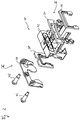
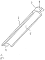
- Fig. 1 you can see one on a guide rail 10 in the direction a rail axis 12 guided carriage 14 with a carriage main body 16 and two at the two axially opposite ends of the carriage main body 16 attached head assemblies 18.
- the guide rail 10 has a mounting surface 20, with which it on a Support base not shown can be fastened, one of the fastening surface 20 opposite head surface 22 and two side surfaces 24 on.
- the guide carriage 14 essentially engages around the guide rail 10 U-shaped, with a web area adjacent to the head surface 22 26 and two interconnected by the web area 26, one of the side surfaces 24 has adjacent leg regions 28. In each of the leg regions 28, two are not shown in detail in FIG.
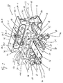
- the head assemblies 18 each consist of one Head piece 32, an intermediate plate 34, a lubricating insert plate 36, a wiper sealing plate 38, a reinforcing plate 40 and Assemble fastening screws 42 with which the aforementioned Components on the carriage main body 16 of the carriage 14 are attached.
- the intermediate plate 34 and the grease insert plate 36 are between the head piece 32 and the main body of the car 16 arranged while the wiper sealing plate 38 and Reinforcing plate 40 axially facing away from the main body 16 of the car Side of the head piece 32 be attached to this.
- the Components of the head assemblies 18 are axially parallel Longitudinal center plane of the entire linear guide device symmetrical educated.
- the head piece 32 sits according to the U-shaped design of the carriage from one Headpiece web 32-1 and headpiece legs 32-2, 32-3 together.
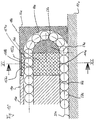
- essentially half-gate deflection surfaces 44 and 46 formed by a semi-cylindrical interface 48 are separated from each other.
- the outside deflection surfaces 44, 46 are part of those already mentioned Deflection guides in the head assemblies of the carriage.
- deflection surfaces 50 and 52 inside the arch which are formed on a deflection body 54 which is integral with the Intermediate plate 34 is formed.
- the inside of the arch lies Deflection surface 50 of the outer deflection surface 44 opposite.
- the inner deflection surface 52 of the outer one is located Deflection surface 46 opposite, so that the deflection surface pairs 50, 44 and 52, 46 each have a substantially half-gate deflection channel for the Form balls of the respective ball loop.
- the intermediate plate 34 is penetrated by ball return holes 62, 64, which the returning balls of the respective ball loop Open access to the return holes in the main body 16 of the car.
- Starting from a contact surface facing the carriage main body 16 66 are attached to the intermediate plate 34 pipe sockets 68, 70, which are made in one piece with the intermediate plate 34 and concentric to the associated ball return hole 62, 64.
- the pipe socket 68, 70 as a positioning aid in Extended end sections of the ball return holes in the main body of the car 16 inserted.
- Head piece 32 On its axial side facing the carriage main body 16 it has Head piece 32 has a contact surface 76 which is for contact with a contact surface 78 of the intermediate plate 34 is determined.
- the intermediate plate 34 comes during assembly with its contact surface 66 on the associated axial end face of the carriage main body 16 to lie. in the The area of the head piece web 32-1 has the intermediate plate 34 essentially the same outline as the headpiece 32 and the main body of the car 16.
- the outline of the Intermediate plate 34 through the molded, in particular molded Deflection body 54 and the pipe socket 68, 70 determined.
- the contact surface 66 laterally next to the pipe socket 68, 70 through a coplanar contact surface 80 supplements that on a step projection 82 of the respective head leg 32-2 or 32-3 is formed.
- the header 32 has lubricant input ports at 84-1, 84-2, 84-3 and 84-4. Each of these lubricant inlet connections is with an associated opening on the axially facing the intermediate plate 34 Connected side of the head piece 32, namely the lubricant input port 84-1 with an opening 86-1, the lubricant input port 84-2 with an opening 86-2, the lubricant inlet connection 84-3 with an opening 86-3 and the lubricant input port 84-4 with an opening 86-4.
- the openings 86-1 and 86-2 open into one Surface 88, which is in the same plane as the contact surface 76 and is surrounded by a circumferential sealing groove 90.
- the intermediate piece 34 On your the intermediate piece 34 has the axially facing side of the head piece 32 a sealing web 92, which when mounting the head assembly lubricant-tight engages in the groove 90 of the head piece 32.
- the openings 86-3 and 86-4 open into one set back from surface 88 Recess 94, the on the intermediate plate 34 is a contour Projection 96 is opposite.
- 86-4 On both sides of the opening pair 86-3, 86-4 is a storage chamber 98 in the head piece web 32-1 Storage of lubricant trained.
- the pantries 98 there are several smaller cross-sections on the intermediate plate 34 Through openings 100 opposite.
- one is formed on the protrusion 96 Ring extension 104 delimits a further passage opening 102-3, which is opposite the opening 86-3 of the head piece 32.
- the lubricant input ports 84-3 and 84-4 can also be used with a be connected to a single common opening, such as opening 86-4.
- a single common opening such as opening 86-4.
- a single passage opening may also be provided, for example the passage opening 102-4.
- the larger section Passage opening 102-4 opens into the projection 96.
- the lubricant inlet holes 84-1 to 84-4 which are attached to the Openings 86-1 to 86-4 connecting channels in the head piece 32, the passage openings 102-1 to 102-4, the storage chambers 98 and the through openings 100 that produce this connection form a lubricant supply room from which the ball loops S1 and S2 optionally with high viscosity grease or with low-viscosity, low-viscosity lubricating oil can be supplied.
- the Lubricant regardless of whether it is grease or lubricating oil, is optionally by one of the lubricant input ports 84-1 to 84-4 in the lubricant supply space introduced.
- This relief-like recess 108 is preferably made of a hard plastic when spraying Intermediate plate 34 formed.
- a suction body 110 forming the lubricating insert plate 36 (see FIG. 6) if desired, inserted under slight tension, which consists of a absorbing lubricating oil and promoting this by capillary action Material exists.
- a textile material, such as felt, is conceivable for this.
- the material of the absorbent body 110 is an open cell Foam, especially a polymer plastic, in its pore system Lubricating oil solely through capillary action without external pressure is evenly distributed over the entire absorbent body 110.
- the U-shaped suction body 110 serves for the simultaneous supply of lubricating oil all ball loops of the carriage and extends to this over the web area of the intermediate plate 34 to both leg areas inside.
- the recess 108 is on the ball loops S1 and S2 through openings 112 (see FIG. 5) with the circulation space of the ball loops S1, S2, especially the one for the load-bearing rows of balls of the ball loops S1, S2 space provided.
- the absorbent body 110 extends and fits with rounded Contact surfaces 114 flush in the in the carriage for the ball loops S1, S2 provided career system.
- S1 ball loops move through the circulation space, S2 past the contact surfaces 114 and are covered with lubricating oil wetted that they lick from the contact surfaces 114.
- the wetting contact of the suction body 110 with the balls of the ball loops S1, S2 takes place in the illustrated embodiment in the transition area between the load-bearing rows of balls of the ball loops S1, S2 and the subsequent rows of deflection bends instead of balls.
- the absorbent body 110 also in other places along the circulation path the balls of the ball loops S1, S2 can reach into the circulation space, for example at the transition between the returning rows of balls of the ball loops S1, S2 and the subsequent deflecting ball rows.
- the grease supply line mentioned is formed in such a way that a slot 116 (see FIG. 6) is provided in the absorbent body 110, which passes through the absorbent body 110 in the axial direction and over the Web area of the absorbent body 110 into both leg areas of the absorbent body 110 is sufficient.
- the slot 116 is so in the absorbent body 110 introduced that the larger cross-sectional openings 102-1, 102-2 and 102-4 of the intermediate plate 34 in the region of the slot 116 lie and are not covered by the absorbent body 110. 6 can be seen a part of the through hole 102-2.
- the smaller ones Through holes 100 are completely through covered the absorbent body 110.
- slot 116 is narrowed so that a pressure relief valve is formed, which in the unpressurized state Passage between a slot area 116 'upstream of the Pressure relief valve 118 and a slot area 116 "downstream of the Pressure relief valve 118 blocks and when a pressure drop is created between the upstream and downstream slot areas opens this passage.
- the material of the absorbent body 110 is for this elastic compressible. It is understood that the pressure relief valve 118 not only by one limited by the material of the absorbent body 110 Narrowing of the slot 116 can be formed, but for example also from a valve lamella integrally formed on the intermediate plate 34, which protrudes into the slot 116.
- the grease soaks into a relief-like recess 108 formed channel 120 (see in particular FIGS. 3 and 5) in which the Grease transported to a puncture channel 122 (see FIGS. 3 and 4) that is in the deflecting body 54 from the side remote from the head piece goes to the side near the head piece.
- Can into the absorbent body 110 the grease does not penetrate because the material of the absorbent body 110 represents a barrier impermeable to grease.
- the grease can also be used between the intermediate plate and the main body of the car do not escape because the intermediate plate 34 is close to the carriage main body is present. Therefore, the grease only has the way through Channel 120 in the puncture channel covered by the absorbent body 110 122.
- the latter is on the semi-cylindrical surface 48 between the two outer deflection surfaces 44, 46 directed and opens into one between the inner deflection surfaces 50, 52 of the deflection body 54 lying flat 124 (see FIG. 4).
- This flattening 124 delimits two with the semi-cylindrical surface 48 opposite it Grease outflow openings, one of which leads to the lower ball loop S1 and the other leads to the upper ball loop S2. Because the one in Fig.
- Analogous operations result when grease passes through the lubricant input ports 84-2 and 84-4 is pressed. When entering fat due to the lubricant input connection 84-3, this is only the case somewhat different from that of the lubricant input port 84-3 assigned passage opening 102-3 in the intermediate plate 34 through the absorbent body 110 is covered. Access to slot area 116 ' can then for example by a groove 126 on the top of the fat Edge of the recess 108 and by one adjoining the groove 126 and recess through to the slot area 116 ' 127 may be possible in the absorbent body 110.
- Recess 127 instead of on the main body of the car facing side of the absorbent body 110 can be such Recess 127 also on the bottom of the recess 108 facing Side of the absorbent body 110 may be provided. Likewise, in the bottom of the recess 108 itself has such a recess 127 be incorporated. In the latter two cases, the groove 126 can be omitted.
- Lubricating oil is supplied through one of the ports 84-1 to 84-4, for example by a central lubricating oil supply system of the linear guide device comprehensive parent machine, which in carries out lubricating oil dosage at periodic intervals the lubricating oil in turn through the openings 86-1 to 86-4 and the Through openings 102-1 to 102-4 in the relief-like recess 108. There it is sucked up by the absorbent body 110.
- Lubricating oil essentially depressurized through one of the lubricant input ports 84-1 to 84-4 to enter, and in such Amount until the absorbent 110 is completely soaked and if desired also the slot area upstream of the valves 118 116 'is filled with lubricating oil.
- This free lubricating oil is then available to the oil-tight blocking pressure relief valves 118, but cannot open so that no through the channel 120 and the puncture channel 122 free lubricating oil can flow out to the ball loops S1, S2.
- the lubricating oil must be filled into the carriage under a certain pressure, thus after saturation of the absorbent body 110 by this lubricating oil is "sweated" and through the smaller cross-sectional openings 100 reaches the pantries 98. It can be under Circumstances for a brief opening of the pressure relief valve 118 come with the possible consequence that free lubricating oil through the gutter 120 and the puncture channel 122 to the outflow openings on the flattened portion 124 flows off. However, one will try the opening pressure of the pressure relief valve 118 to be set so large that at normal oil filling pressures no opening of the pressure relief valve 118 occurs.
- the free lubricating oil in the storage chambers 98 and in the slot 116 enables continuous aftercare of the absorbent body 110, so that it doesn't dry out. Due to its suction effect, the sucks Absorbent body 110 always has such quantities of lubricating oil from the storage chambers 98 and the slot 116 from that its complete soaking preserved. It is advantageous that with grease lubrication the pantries 98 should not be filled with grease as this gives access to the Storage chambers 98 enable passage openings of smaller cross section 100 are blocked by the absorbent body 110. The accumulation a larger amount of "dead", unused grease in the Carriage is avoided, which is beneficial to the overall affects the amount of grease to be entered in the carriage.
- the seal between the contact surface 76 of the head piece 32 and the contact surface 78 of the intermediate plate 34 and the seal between the contact surface 66 of the intermediate plate 34 and the opposite one End face of the carriage main body 16 is replaced by a suitable one Choice of materials and / or by a suitable arrangement of Sealing elements on the intermediate plate 34 and / or on the head piece 32 causes.
- a sealing element is that in the groove 90 of the head piece 32 engaging sealing web 92 on the intermediate plate 34.
- sealing lips such as For example, indicated at 128 in FIG. 5.
- the absorbent body 110 takes over no sealing function for lubricating oil and neither can take over because he yes, even if he is under tension when installing was set to complete the relief To cause recess 108 with its entire volume Lubricating oil is saturated.
- Via the slot 116 and the passage openings 102-1, 102-2 and 102-4 is at least between the lubricant input ports 84-1, 84-2 and 84-4 a connection.
- lubricant inlet connections Fill lubricant, it is therefore necessary to to seal unused connections with a blind plug, while the connection used is provided with a grease nipple.
- the connections 84-1 to 84-4 individually or in groups (such as the connection group 84-3, 84-4) to assign a valve element acting as a check valve, through which the respective connection or the respective connection group of the other connections.
- valve elements can For example, be designed as valve flaps on the head piece 32 or the intermediate plate 34 attached, in particular in one piece are integrally formed, and the openings 86-1 to 86-4 or the passage openings Seal 102-1 to 102-4. 3 is a dashed line the valve flap 128 closing the opening 86-1 is shown, which deflects when applying lubricant pressure to port 84-1 and opens the opening 86-1. It is understood that in this case between surface 88 of head 32 and the opposite Surface 106 of the intermediate plate 34, a space may be present must, which allows the deflection of the valve flap 128.
- Fig. 7 shows a lubricating half-shell 130, each in the ball return channels the carriage main body 16 is inserted and a continuation the lubricating oil supply capillary line formed by the suction body 110 in the area of the returning rows of balls of the ball loops S1, S2 forms.
- the Lubricant half-shell 130 With its concave inner surface 132, the Lubricant half-shell 130 a tread for the returning balls of the respective ball loop S1, S2.
- the lubricating half-shell 130 consists of a lubricating oil absorbing and promoting by capillary action Material. Again, an open-cell foam comes into question. Because of its high wear resistance, however, a sintered metal, especially sintered bronze, preferred.
- the lubricating half-shell 130 each has a protruding longitudinal end Tongue 134 in the form of a segment of a circle, which has a positioning surface 135 to a flattening 136 (FIG. 5) of one of the positioning rings 68, 70 becomes.
- the lubricating half-shell abuts with an end abutment surface 138 thereby on the absorbent body inserted into the intermediate plate 34 110 on, so that the lubricating half-shell 130 lubricating oil from the absorbent body 110 can absorb.
- the reinforcement plate preferably made of sheet metal 40 with locking recesses 140 on locking projections 142 des Head piece 32 can be snapped.
- the outline of the guide rail contour-matched and with a double sealing lip arrangement 144 on the Sealing plate 38 bearing against the guide rail is between the head piece 32 and the reinforcement plate 40 in a recess 146 on the side of the head piece facing away from the main body of the car 32 added.
- On the reinforcement plate 40 are internally threaded bushings 148 formed in one piece, the 40 when mounting the reinforcing plate on the header 32 in registration with the lubricant input ports 84-1, 84-2 and 84-4 forming connection holes in the head piece 32nd reach.
- a grease nipple for Connection of a lubricant filling device In the internally threaded bushings 148, a grease nipple for Connection of a lubricant filling device. It can Blind plugs are also used to connect unused lubricant inlet connections to close. Damage to the reinforcement plate 40 due to the screwing in of a grease nipple are due to the In contrast, the metal material of the reinforcement plate 40 is not to be feared to the head piece 32, which is usually molded from plastic which is too easy to screw in a grease nipple Damage to the plastic material could result.
- the lubricant input port 84-3 is in the present embodiment no internally threaded bushing assigned to the reinforcement plate 40. However, it is understood that the reinforcing plate 40 also over the Lubricant input port 84-3 can range. Holes 150 in the Reinforcing plate 40 serve for the passage of the fastening screws shown in FIG. 2 42.
- the oil fill line is in turn connected to an oil supply unit, which a desired Volume of lubricating oil that is used to fill the guide carriage with oil is needed, can deliver.
- the oil delivery unit can handle this volume of lubricating oil deliver according to a specified delivery program, for example in the Way that it has a constant over a predetermined period of time Oil flow emits under a constant oil pressure, but also in such a way that the oil flow and / or the oil pressure change over time Possess history.
- the delivery program of the oil delivery unit can be changeable by an operator if desired and depending to be determined according to the application.
- the oil passes from the relevant input connection 84-1 to 84-4 via the associated opening 86-1 to 86-4 and the associated passage opening 102-1 to 102-4 in the recess 108 in the intermediate plate 34. If the lubricating oil at one of the input ports 84-1, 84-2 and 84-4 has been filled, it occurs in the absorbent body 110 recessed slot area 116 '. There it spreads and becomes and after absorbed by the absorbent body 110.
- Lubricating oil on the Input port 84-3 is filled after passing through the Passage opening 102-3 directly onto the absorbent body 110 the oil flow at the input port 84-3 the absorbency of the Absorbent body exceeds 110, it can happen that from the passage opening 102-3 escaping lubricating oil that is not immediately from the Absorbent body 110 is sucked up, the material of the absorbent body 110 pushes something away and a path past the absorbent body 110 in slits the slot area 116 '.
- the suction body is filled when the guide carriage is filled for the first time 110 is still completely dry or after a predetermined operating time the linear guide device or a predetermined distance traveled Path of the guide carriage the oil supply in the guide carriage has run out and the absorbent 110 is no longer included If the lubricating oil is saturated, the absorbent body 110 sucks it into the slot area 116 'of lubricating oil that has run in or through the passage opening 102-3 inflowing lubricating oil in its land area, so here an oil enrichment can be observed. This leaves 110 in the absorbent body a saturation gradient between its web area and the Leak areas having contact surfaces 114 arise.
- Unbound lubricating oil can reach up to the in the slot area 116 ' Distribute shut-off valves 118. If the shut-off valves 118 are caused by oil pressure could open free oil through the downstream slot areas 116 '', the channels 120 and the puncture channels 122 to the Grease outflow openings on the flats 124 flow. To do this prevent, the oil filling is carried out so that in the upstream slot area 116 'at no time builds up oil pressure, which exceeds the opening pressure of the valves 118.
- the oil delivery unit the oil filling pressure or / and the flow rate of the lubricating oil initially on a comparative basis maintains high level as long as the slot area 116 'still empty or little filled. If the slot area 116 'then gradually fills with lubricating oil because of the absorbency and the pumping capacity of the absorbent body 110 is not sufficient to apply it to the absorbent body 110 suitable lubricating oil in the thigh area quickly enough to remove the contact surfaces 114, the oil delivery unit lowers the Oil filling pressure and / or the flow rate of the lubricating oil, so that in the slot area 116 'in turn can not build up oil pressure that the Opening pressure of the shut-off valves 118 exceeds.
- the delivery program of the oil delivery unit can be designed in this way be that the remaining oil quantities are below a very small Filling pressure and be filled very slowly. Because it is from it assume that the absorbent body 110 is approximately at this time is completely saturated with lubricating oil and only small empty spaces in the Slot area 116 'and in the storage chambers 98 for receiving them Remaining amounts of lubricating oil remain.
- shut-off valves 118 Should the oil fill in unintentionally in the short term build up oil pressure in the upstream slot region 116 ' a brief opening of the shut-off valves 118 leads to parts of the unbound lubricating oil from the upstream slot area 116 ' get into the downstream slot area 116 ′′. This lubricating oil however, it may also be downstream of the shutoff valves 118 from the absorbent body 110 are sucked up, because namely the boundary walls of the downstream slot area reserved for grease transport only 116 '' partially from the suction surface of the suction body 110 are formed.
- shut-off valve 118 Connection between the grease transport path and the oil transport path, which allows lubricating oil to pass through the shut-off valves 118 still divert into the oil transportation route and drain this To prevent lubricating oil at the grease points.
- the absorbent body 110 is one that is impenetrable to fat Represents a barrier and the grease does not form between the intermediate plate 34 and can escape from the car main body 16, the upstream one fills up Slit area 116 'gradually until it is in the slit area 116 'has built up a bold print which corresponds to the opening pressure of the Shut-off valves exceed 118.
- the fat then flows into the downstream Slot areas 116 '' from where it passes through the channels 120 and Puncture channels 122 to the grease outlets on the flattenings 124 flows off. This further transport of the grease to the grease outflow openings however, it only takes place under the pressure of the grease gun added fat.
- FIGS. 10-12 are the same or equivalent components as in 1-9 provided with the same reference numerals, but supplemented by a small letter. Unless otherwise stated below results in order to avoid repetitions on the concerned References to FIGS. 1-9 referenced. It is understood that in In connection with FIGS. 1-9, features described in FIGS. 10-12 are not shown, however, in the exemplary embodiments of FIG. 10 - 12 - modified if necessary - can be used, and vice versa.
- the Lubricating insert body 36a corresponds to the basic shape of the guide carriage 14a U-shaped. However, it does not form an insert, that as in the embodiment of FIGS. 1-9 in a relief Recess of an intermediate plate is inserted. Rather, it forms itself a kind of intermediate plate that defines the axial space between the head piece 32 and the carriage main body 16a substantially completely filled out.
- the lubricating insert body 36a can act as a capillary body absorbing lubricating oil be formed, of which the balls 58a lubricating oil without action an external lubricating oil pressure.
- the lubricating insert body 36a can consist of solid lubricant, for example made of pressed graphite. Even with such a solid lubricant body finds a lubricant transfer to the balls 58a instead when the latter roll on the solid lubricant body.
- the lubricating insert body 36a made of one material with a lubricant admixture.
- a lubricant-containing polymer body made from a basic material based on polyethylene with an addition of lubricant based on paraffin is made.
- the Lubricant release especially due to the frictional heat of the Rolling balls 58a and through the raceway of the circulation space supported mechanical pressure action on the lubricating insert body 36a become.
- the latter two alternative solutions basically also for the material of the lubricating insert body 36a in the embodiment of FIGS. 1-9 for the lubricating insert plate there 36 are conceivable.
- the lubricating insert body 36a is expediently axially aligned arranged between the head piece 32a and the carriage main body 16a Housing 152a is housed to prevent lubricant leakage to prevent the outside of the carriage 14a and the To protect lubricating insert body 36a from external influences. At It is basically sufficient dimensional stability of the lubricating insert body 36a not excluded, without the housing 152a.
- the lubricating insert body 36a integrally with the deflecting body 54a is formed so that not only in the axial End areas of the load-bearing and / or the returning row of balls Lubrication of the balls 58a takes place, but also in the area of Deflection ball rows.
- the lubricating insert body 36a a return bore 154a which is completely from the grease insert body 36a is enclosed and flush with the ball return channel of the carriage main body 16a and to the deflector of the head piece 32a connects.
- the return bore 154a is slightly larger than that Dimensioned ball cross-section.
- a lip-like projection 156a protrudes a circumferential point in the return bore 154a and presses the returning balls 58a under slight elastic bias a lubricating contact surface diametrically opposite the projection 156a 158a.
- the lip projection 156a is so dimensioned and so flexibly designed that the passage of the balls 58a through the return bore 154a is essentially unhindered, but that at the same time the returning balls 58a safely and extensively against the peripheral wall the return bore 154a in the area of the lubrication contact surface 158a can be pressed. In this way, a reliable and ensure sufficient lubrication of balls 58a. In particular when a low mechanical pressure is required to achieve a Removal of lubricant from the material structure of the lubricant insert 36a to effect this mechanical pressure without apply another by means of the lip projection 156a.
- FIG. 12 shows an exemplary embodiment modified compared to FIGS. 10 and 11.
- This additional supply of lubricant consists of a in the embodiment of FIG Additional lubricating body 162b, which counteracts by means of a preload spring 164b the return balls 58b is biased and with a contact surface 166b is in lubricating contact with the returning balls 58b.
- the additional lubricating body 162b expediently consists of the same material as the lubricating insert body 36b and reworks the same lubrication principle.
- the housing 160b can be removed without disassembly of the head piece 32b can be removed from the guide carriage 14b, so that an easy replacement of the additional lubricating body 162b is possible if whose lubricating capacity has been used up or under changed operating conditions the linear guide device, such as changed working temperatures, a lubricant with a different lubricant composition should be used. If lubrication of the balls 58b with lubricating oil, the housing 160b can also be used Stocking a lot of free lubricating oil can be used which in a manner not shown with the lubricating insert body 36b in Connection is established so that a constant after-supply of the lubricating insert body 36b is guaranteed with fresh lubricating oil.
Landscapes
- Engineering & Computer Science (AREA)
- General Engineering & Computer Science (AREA)
- Mechanical Engineering (AREA)
- Bearings For Parts Moving Linearly (AREA)
- Rolling Contact Bearings (AREA)
Abstract
Description
- Fig. 1
- eine perspektivische Gesamtdarstellung eines Ausführungsbeispiels der erfindungsgemäßen Linearführungseinrichtung;
- Fig. 2
- eine perspektivische Explosionsdarstellung einer Kopfbaugruppe eines Führungswagens der Linearführungseinrichtung der Fig. 1;
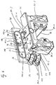
- Fig. 3
- ein Kopfstück und eine Zwischenplatte der Kopfbaugruppe der Fig. 2, gesehen in Blickrichtung des Pfeils III in Fig. 2;
- Fig. 4
- das Kopfstück und die Zwischenplatte der Fig. 3, gesehen in Blickrichtung des Pfeils IV in Fig. 3;
- Fig. 5
- die Kopfbaugruppe der Fig. 2 in einem zusammengebauten Zustand in einer Ansicht ähnlich Fig. 3, jedoch ohne eine in die Zwischenplatte einzulegende Schmiereinsatzplatte;
- Fig. 6
- die linke Hälfte der in Fig. 5 gezeigten Kopfbaugruppe, jedoch mit eingelegter Schmiereinsatzplatte;
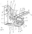
- Fig. 7
- in perspektivischer Darstellung eine in eine Rücklaufbohrung des Führungswagens einzulegende Schmierhalbschale;
- Fig. 8
- in perspektivischer Darstellung die Zwischenplatten zweier Kopfbaugruppen des Führungswagens mit dazwischen angeordneten Schmierhalbschalen;
- Fig. 9
- eine perspektivische Expiosionsansicht des Kopfstücks, einer Abstreiferdichtplatte und einer Armierungsplatte der Kopfbaugruppe, gesehen in Blickrichtung des Pfeils IX in Fig. 2;
- Fig. 10
- einen Längsschnitt durch ein weiteres Ausführungsbeispiel der erfindungsgemäßen Linearführungseinrichtung;
- Fig. 11
- einen längs der Linie XI-XI der Fig. 10 genommenen Querschnitt und
- Fig. 12
- einen Längsschnitt durch ein weiteres Ausführungsbeispiel der erfindungsgemäßen Linearführungseinrichtung.
Claims (50)
- Linearführungseinrichtung, umfassendeine Führungsschiene (10) mit einer Längsachse (12),mindestens einen Führungswagen (14), welcher auf der Führungsschiene (10) unter Verwendung mindestens einer in einem Umlaufraum des Führungswagens (14) umlaufenden Wälzkörperschleife (S1,S2) in Richtung der Längsachse (12) geführt ist, wobei diese Wälzkörperschleife (S1,S2) eine tragende Wälzkörperreihe in gleichzeitigem Eingriff mit einer tragenden Laufbahn (30) der Führungsschiene (10) und mit einer tragenden Laufbahn des Führungswagens (14), ferner eine rücklaufende Wälzkörperreihe sowie zwei Umlenkbogen-Wälzkörperreihen aufweist,
wobei weiter der Führungswagen (14) von einem Wagenhauptkörper (16) im Längenbereich der tragenden Wälzkörperreihe und von Kopfstückeinheiten (32) an den axial beabstandeten Enden des Wagenhauptkörpers (16) gebildet ist,
wobei weiter Umlenkführungen (44,46,50,52) für die Umlenkbogen-Wälzkörperreihen wenigstens zum Teil an diesen Kopfstückeinheiten (32) ausgebildet sind,
wobei weiter Schmierstoffbedarf an mindestens einem Teil der Wälzflächen (30,44,46,50,52,60,114,132,58) besteht und zur Befriedigung dieses Schmierstoffbedarfs ein Schmierstoffwegesystem (84-1 bis 84-4,86-1 bis 86-4,98,100,102-1 bis 102-4,110,114,116,120,122) in dem Führungswagen (14) vorgesehen ist, welches von einem Schmierstoffversorgungsraum (84-1 bis 84-4,86-1 bis 86-4,98,100,102-1 bis 102-4) des Führungswagens (14) zu Wälzflächen (114,132,50,52) führt,
und wobei dieses Schmierstoffwegesystem (84-1 bis 84-4,86-1 bis 86-4,98,100,102-1 bis 102-4,110,114,116,120,122) wenigstens zum Teil in einem Grenzbereich (34) zwischen mindestens einer Kopfstückeinheit (32) und dem Wagenhauptkörper (16) untergebracht ist,
dadurch gekennzeichnet,
daß eine an den Schmierstoffversorgungsraum (84-1 bis 84-4,86-1 bis 86-4,98,100,102-1 bis 102-4) angeschlossene und wenigstens zum Teil in dem Grenzbereich (34) annähernd in Umfangsrichtung der Führungsschiene (10) verlaufende Schmierölzuführleitung (110,130) wenigstens auf einem Teil ihrer Länge von einer druckgefälleunabhängig fördernden Schmierölzuführkapillarleitung (110,130) gebildet ist, welche in mindestens einem Schleckbereich (114,132) in Schleckkontakt mit Wälzkörpern (58) der mindestens einen Wälzkörperschleife (S1,S2) oder mit der tragenden Laufbahn (30) der Führungsschiene (10) steht. - Linearführungseinrichtung nach Anspruch 1,
dadurch gekennzeichnet,
daß der Führungswagen (14) im wesentlichen U-förmig ausgebildet ist mit einem Stegbereich (26), welcher einer Kopffläche (22) der Führungsschiene (10) benachbart ist, und mit Schenkelbereichen (28), welche je einer Seitenfläche (24) der Führungsschiene (10) benachbart sind, daß die tragende Wälzkörperreihe mindestens je einer Wälzkörperschleife (S1,S2) zwischen je einem Schenkelbereich (28) und je einer Seitenfläche (24) der Führungsschiene (10) angeordnet ist und daß die Schmierölzuführleitung (110,130) entsprechend U-förmig über den Stegbereich (26) und die Schenkelbereiche (28) verläuft. - Linearführungseinrichtung nach Anspruch 2,
dadurch gekennzeichnet,
daß sich die Schmierölzuführkapillarleitung (110,130) annähernd über die Länge des Schenkelbereichs (28) erstreckt. - Linearführungseinrichtung nach Anspruch 3,
dadurch gekennzeichnet,
daß sich die Schmierölzuführkapillarleitung (110,130) auch zumindest über einen Teil des Stegbereichs (26) erstreckt. - Linearführungseinrichtung nach einem der Ansprüche 2 - 4,
dadurch gekennzeichnet,
daß die Schmierölzuführkapillarleitung (110,130) eine im wesentlichen U-förmig verlaufende Leitungsstrecke (110) besitzt, welche sich von der tragenden Wälzkärperreihe der mindestens einen Wälzkörperschleife (S1,S2) des einen Schenkelbereichs (28) zu der tragenden Wälzkörperreihe der mindestens einen Wälzkörperschleife (S1,S2) des anderen Schenkelbereichs (28) erstreckt. - Linearführungseinrichtung nach einem der Ansprüche 2 - 5,
dadurch gekennzeichnet,
daß der Schmierstoffversorgungsraum (84-1 bis 84-4,86-1 bis 86-4,98,100,102-1 bis 102-4) im Stegbereich (26) des U-förmigen Führungswagens (14) angeordnet ist, insbesondere im Stegbereich (32-1) mindestens einer Kopfstückeinheit (32). - Linearführungseinrichtung nach einem der Ansprüche 1 - 6,
dadurch gekennzeichnet,
daß der Schleckbereich (114,132) sich über wenigstens einen Teil, insbesondere über einen wesentlichen Teil, der Länge der tragenden oder/und der rücklaufenden Wälzkörperreihe erstreckt. - Linearführungseinrichtung nach Anspruch 7,
dadurch gekennzeichnet,
daß der Schleckbereich (114,132) von einer Lauffläche des Umlaufraums gebildet ist. - Linearführungseinrichtung nach einem der Ansprüche 1 - 8,
dadurch gekennzeichnet,
daß das Schmierstoffwegesystem (84-1 bis 84-4,86-1 bis 86-4,98,100,102-1 bis 102-4,110,114,116,120,122) wenigstens zum Teil in einer Zwischenplatteneinheit (34) untergebracht ist, welche zwischen einem axialen Ende des Wagenhauptkörpers (16) und der zugehörigen Kopfstückeinheit (32) angeordnet ist. - Linearführungseinrichtung nach Anspruch 9,
dadurch gekennzeichnet,
daß die Zwischenplatteneinheit (34) wenigstens zum Teil aus schmieröldichtem Werkstoff, insbesondere Kunststoff, besteht. - Linearführungseinrichtung nach Anspruch 9 oder 10,
dadurch gekennzeichnet,
daß die Zwischenplatteneinheit (34) an dem Wagenhauptkörper (16) und/oder an der Kopfstückeinheit (32) schmieröldicht anliegt. - Linearführungseinrichtung nach einem der Ansprüche 9 - 11,
dadurch gekennzeichnet,
daß die Zwischenplatteneinheit (34) eine Ausnehmung (108) zur wenigstens teilweisen Aufnahme der Schmierölzuführkapillarleitung (110,130) aufweist. - Linearführungseinrichtung nach Anspruch 12,
dadurch gekennzeichnet,
daß die Ausnehmung (108) wenigstens auf einem Teil ihrer in Umfangsrichtung der Führungsschiene (10) verlaufenden Länge von der Schmierölzuführkapillarleitung (110,130) im wesentlichen vollständig ausgefüllt ist. - Linearführungseinrichtung nach Anspruch 12 oder 13,
dadurch gekennzeichnet,
daß die Ausnehmung (108) in der Zwischenplatteneinheit (34) reliefartig ausgebildet ist und zum Wagenhauptkörper (16) hin freiliegt. - Linearführungseinrichtung nach einem der Ansprüche 12 - 14,
dadurch gekennzeichnet,
daß die Ausnehmung (108) Verbindungsöffnungen (100,102-1 bis 102-4) aufweist, durch welche sie mit dem Schmierstoffversorgungsraum (84-1 bis 84-4,86-1 bis 86-4,98,100,102-1 bis 102-4) in Verbindung steht. - Linearführungseinrichtung nach einem der Ansprüche 9 - 15,
dadurch gekennzeichnet,
daß an der Zwischenplatteneinheit (34) eine bogeninnere Umlenkfläche (50,52) für die jeweilige Umlenkbogen-Wälzkörperreihe angebracht ist. - Linearführungseinrichtung nach Anspruch 14 und 16,
dadurch gekennzeichnet,
daß die bogeninnere Umlenkfläche (50,52) auf der von der reliefartigen Ausnehmung (108) abgelegenen Seite der Zwischenplatteneinheit (34) angeformt ist. - Linearführungseinrichtung nach einem der Ansprüche 2 - 17,
dadurch gekennzeichnet,
daß in mindestens einem Schenkelbereich (28) des Führungswagens (14) eine Mehrzahl von Wälzkörperschleifen (S1,S2) vorgesehen ist und daß die Schmierölzuführkapillarleitung (110,130) in Schleckkontakt mit den Wälzkörpern (58) mehrerer Wälzkörperschleifen (S1,S2) steht. - Linearführungseinrichtung nach einem der Ansprüche 1 - 18,
dadurch gekennzeichnet,
daß das Schmierstoffwegesystem (84-1 bis 84-4,86-1 bis 86-4,98,100,102-1 bis 102-4,110,114,116,120,122) eine Schmierfettzuführleitung (116,120,122) von dem Schmierstoffversorgungsraum (84-1 bis 84-4,86-1 bis 86-4,98,100,102-1 bis 102-4) zu mindestens einer Schmierfettmündungsstruktur (124) umfaßt, an welcher die Schmierfettzuführleitung (116,120,122) in den Umlaufraum oder in die Laufbahn (30) der Führungsschiene (10) einmündet. - Linearführungseinrichtung nach Anspruch 19,
dadurch gekennzeichnet,
daß die Schmierfettzuführleitung (116,120,122) und die Schmierölzuführkapillarleitung (110,130) wenigstens auf einem Teil ihrer Länge parallel zueinander verlaufen, wobei die Schmierölzuführkapillarleitung (110,130) mindestens einen Teil der Querschnittsbegrenzung der Schmierfettzuführleitung (116,120,122) bildet. - Linearführungseinrichtung nach Anspruch 20,
dadurch gekennzeichnet,
daß die Schmierfettzuführleitung (116,120,122) wenigstens auf einem Teil ihrer Länge in einem Schlitz (116) der Schmierölzuführkapillarleitung (110,130) verläuft. - Linearführungseinrichtung nach einem der Ansprüche 19 - 21,
dadurch gekennzeichnet,
daß die Schmierälzuführkapillarleitung (110,130) wenigstens teilweise in einer Zwischenplatteneinheit (34) untergebracht ist, welche im Bereich einer Umlenkbogen-Wälzkörperreihe einen bogeninneren Umlenkkörper (54) bildet, und daß im Anschluß an einen von der Schmierölzuführkapillarleitung (110,130) wenigstens teilweise begrenzten Leitungsabschnitt (116) der Schmierfettzuführleitung (116,120,122) diese innerhalb des Umlenkkörpers (54) bis zu mindestens einer Schmierfettmündungsstruktur (124) fortgesetzt ist. - Linearführungseinrichtung nach Anspruch 22, dadurch gekennzeichnet,
daß der Umlenkkörper (54) einer Mehrzahl von Wälzkörperschleifen (S1,S2) gemeinsam ist und daß die Schmierfettzuführleitung (116,120,122) innerhalb des Umlenkkörpers (54) zu mehreren Wälzkörperschleifen hin verzweigt (bei 124) ist. - Linearführungseinrichtung nach Anspruch 23,
dadurch gekennzeichnet,
daß der Umlenkkörper (54) zwischen zwei nebeneinander liegenden Umlenkflächen (50,52) für benachbarte Wälzkörperschleifen (S1,S2) eine Schmierfettmündungsstruktur (124) besitzt. - Linearführungseinrichtung nach einem der Ansprüche 19 - 24,
dadurch gekennzeichnet,
daß die Schmierfettzuführleitung (116,120,122) eine Absperrstelle (118) enthält, welche stromaufwärts der Schmierfettmündungsstruktur (124) liegt und durch Schmierfettdruck geöffnet werden kann. - Linearführungseinrichtung nach einem der Ansprüche 1 - 25,
dadurch gekennzeichnet,
daß an dem Führungswagen (14) eine Mehrzahl von wahlweise zur Schmierstoffeingabe benutzbaren Schmierstoffeingabeanschlüssen (84-1 bis 84-4) angebracht ist, daß einzelnen oder Gruppen solcher Schmierstoffeingabeanschlüsse (84-1 bis 84-4) jeweils ein Ventilelement (128) zugeordnet ist und daß diese Ventilelemente (128) voneinander derart unabhängig sind, daß bei Anlegen eines vorbestimmten Schmierstoffeingabedrucks an einem der Schmierstoffeingabeanschlüsse (84-1 bis 84-4) nur das diesem zugehörige Ventilelement (128) öffnet. - Linearführungseinrichtung nach Anspruch 26,
dadurch gekennzeichnet,
daß die Ventilelemente (128) innerhalb einer Kopfstückeinheit (32) und/oder an einer Zwischenplatteneinheit (34) angebracht sind, welche zwischen der Kopfstückeinheit (32) und dem Wagenhauptkörper (16) liegt. - Linearführungseinrichtung nach Anspruch 27,
dadurch gekennzeichnet,
daß die Ventilelemente (128) aus dem jeweiligen Werkstoff der Kopfstückeinheit (32) bzw. der Zwischenplatteneinheit (34) gebildet sind. - Linearführungseinrichtung nach einem der Ansprüche 1 - 28,
dadurch gekennzeichnet,
daß Schmierstoffeingabemittel (84-1 bis 84-4) an dem Führungswagen (14) angeordnet sind, welche an den Schmierstoffversorgungsraum (84-1 bis 84-4,86-1 bis 86-4,98,100,102-1 bis 102-4) angeschlossen sind. - Linearführungseinrichtung nach Anspruch 29,
dadurch gekennzeichnet,
daß der Schmierstoffversorgungsraum (84-1 bis 84-4,86-1 bis 86-4,98,100,102-1 bis 102-4) durch ein gemeinsames Schmierstoffeingabemittel (84-1 bis 84-4) wahlweise mit Schmieröl oder mit Schmierfett beschickbar ist. - Linearführungseinrichtung nach Anspruch 29 oder 30,
dadurch gekennzeichnet,
daß die Schmierstoffeingabemittel (84-1 bis 84-4) an einem Kunststoffteil, insbesondere an einer Kopfstückeinheit (32) des Führungswagens (14), angebracht sind. - Linearführungseinrichtung nach Anspruch 31,
dadurch gekennzeichnet,
daß die Schmierstoffeingabemittel (84-1 bis 84-4) eine Mehrzahl von Schmierstoffeingabeanschlüssen (84-1 bis 84-4) umfassen und daß an dem Kunststoffteil (32) ein Armierungsteil (40), insbesondere aus metallischem Werkstoff, angebracht ist, welcher Anschlußkomponenten (148) für die Schmierstoffeingabeanschlüsse (84-1 bis 84-4) trägt. - Linearführungseinrichtung nach Anspruch 32,
dadurch gekennzeichnet,
daß die Anschlußkomponenten (148) als Innengewindebuchsen ausgebildet sind, welche mit jeweils einer Anschlußbohrung der Schmierstoffeingabeanschlüsse (84-1 bis 84-4) in Deckung stehen. - Linearführungseinrichtung, umfassendeine Führungsschiene (10) mit einer Längsachse (12),mindestens einen Führungswagen (14), welcher auf der Führungsschiene (10) unter Verwendung mindestens einer in einem Umlaufraum des Führungswagens (14) geführten Wälzkörperschleife (S1,S2) in Richtung der Längsachse (12) geführt ist, wobei diese Wälzkärperschleife (S1,S2) eine tragende Wälzkörperreihe in gleichzeitigem Eingriff mit einer tragenden Laufbahn (30) der Führungsschiene (10) und mit einer tragenden Laufbahn des Führungswagens (14), ferner eine rücklaufende Wälzkörperreihe sowie zwei Umlenkbogen-Wälzkörperreihen aufweist,
wobei Schmierstoffbedarf an mindestens einem Teil der Wälzflächen (30,44,46,50,52,60,114,132,58) besteht und zur Befriedigung dieses Schmierstoffbedarfs ein Schmierstoffwegesystem (84-1 bis 84-4,86-1 bis 86-4,98,100,102-1 bis 102-4,110,114,116,120,122) in dem Führungswagen (14) vorgesehen ist, welches von einem Schmierstoffversorgungsraum (84-1 bis 84-4,86-1 bis 86-4,98,100,102-1 bis 102-4) des Führungswagens (14) zu Wälzflächen (114,132,50,52) führt, insbesondere nach einem der Ansprüche 1 - 33,
dadurch gekennzeichnet,
daß an den Schmierstoffversorgungsraum (84-1 bis 84-4,86-1 bis 86-4,98,100,102-1 bis 102-4) eine Schmierölzuführleitung (110,130) und eine Schmierfettzuführleitung (116,120,122) angeschlossen sind, daß die Schmierölzuführleitung (110,130) auf wenigstens einem Teil ihrer Länge von einer druckgefälleunabhängig fördernden Schmierölzuführkapillarleitung(110,130) gebildet ist, welche in mindestens einem Schleckbereich (114,132) in Schleckkontakt mit Wälzkörpern (58) der mindestens einen Wälzkörperschleife (S1,S2) oder mit der tragenden Laufbahn (30) der Führungsschiene (10) steht, daß die Schmierfettzuführleitung (116,120,122) an mindestens einer Schmierfettmündungsstruktur (124) in den Umlaufraum oder die tragende Laufbahn (30) der Führungsschiene (10) einmündet und daß in der Schmierfettzuführleitung (116,120,122) stromaufwärts der Schmierfettmündungsstruktur (124) eine Absperreinrichtung (118) vorgesehen ist, welche durch Schmierfettdruck geöffnet werden kann. - Linearführungseinrichtung nach Anspruch 34,
dadurch gekennzeichnet,
daß die Schmierölzuführkapillarleitung (110,130) mindestens einen wesentlichen Teil der Länge der Schmierölzuführleitung (110,130) zwischen dem Schmierstoffversorgungsraum (84-1 bis 84-4,86-1 bis 86-4,98,100,102-1 bis 102-4) und dem Schleckbereich (114,132) einnimmt. - Linearführungseinrichtung nach Anspruch 34 oder 35,
dadurch gekennzeichnet,
daß sich der Schleckbereich (114,132) über mindestens einen wesentlichen Teil der Länge der tragenden oder/und der rücklaufenden Wälzkörperreihe erstreckt. - Linearführungseinrichtung nach einem der Ansprüche 34 - 36,
dadurch gekennzeichnet,
daß die Schmierölzuführkapillarleitung (110,130) als Abdichtung für druckgefällebedingten freien Schmieröl- und Schmierfettzufluß zu dem Schleckbereich (114,132) wirksam ist. - Linearzuführungseinrichtung nach einem der Ansprüche 34 - 37,
dadurch gekennzeichnet,
daß die Schmierfettzuführleitung (116,120,122) in ihrem Abschnitt stromabwärts der Absperreinrichtung (118) im wesentlichen drosselfrei ist. - Linearführungseinrichtung, umfassendeine Führungsschiene (10) mit einer Längsachse (12),mindestens einen Führungswagen (14), welcher auf der Führungsschiene unter Verwendung mindestens einer in einem Umlaufraum des Führungswagens umlaufenden Wälzkörperschleife (S1,S2) in Richtung der Längsachse geführt ist, wobei diese Wälzkörperschleife eine tragende Wälzkörperreihe in gleichzeitigem Eingriff mit einer tragenden Laufbahn (30) der Führungsschiene und mit einer tragenden Laufbahn (60) des Führungswagens, ferner eine rücklaufende Wälzkörperreihe sowie zwei Umlenkbogen-Wälzkörperreihen aufweist,
wobei weiter der Führungswagen einen Wagenhauptkörper (16) im Längenbereich der tragenden Wälzkörperreihe und Kopfstückeinheiten (32) axial beidseits des Wagenhauptkörpers aufweist, wobei weiter Umlenkführungen (44,46,50,52) für die Umlenkbogen-Wälzkörperreihen wenigstens zum Teil an diesen Kopfstückeinheiten ausgebildet sind,
wobei weiter ein Schmierstoffversorgungssystem (84-1 bis 84-4, 86-1 bis 86-4, 98,100,102-1 bis 102-4, 110,114,116,120,122) in dem Führungswagen vorgesehen ist, welches zu Schmierbedarfszonen (114,132,50,52) führt, und wobei dieses Schmierstoffversorgungssystem wenigstens zum Teil in einem Grenzbereich zwischen mindestens einer Kopfstückeinheit und dem Wagenhauptkörper untergebracht ist,
insbesondere nach einem der Ansprüche 1 - 38,
dadurch gekennzeichnet,
daß eine wenigstens zum Teil in dem Grenzbereich annähernd in Umfangsrichtung der Führungsschiene verlaufende Schmierstoffversorgungsstrecke (110,130) des Schmierstoffversorgungssystems wenigstens auf einem Teil ihrer Länge von einer Schmierkörperanordnung (36) aus Schmierstoff speicherndem Material gebildet ist, welche mit einem Schmierstoffabgabebereich (114) in Benetzungskontakt mit Wälzkörpern (58) der mindestens einen Wälzkörperschleife oder/und mit Oberflächenbereichen (30) der Führungsschiene angeordnet ist. - Linearführungseinrichtung nach Anspruch 39,
dadurch gekennzeichnet,
daß die Schmierkörperanordnung (36) aus einem Schmieröl durch Kapillarwirkung fördernden Saugmaterial gebildet ist. - Linearführungseinrichtung nach Anspruch 39,
dadurch gekennzeichnet,
daß die Schmierkörperanordnung (36a) aus einem Material gebildet ist, dessen Zusammensetzung wenigstens einen Schmierstoffanteil aufweist. - Linearführungseinrichtung nach einem der Ansprüche 39 - 41,
dadurch gekennzeichnet,
daß der Führungswagen (14) im wesentlichen U-förmig ausgebildet ist mit einem Stegbereich (26), welcher einer Kopffläche (22) der Führungsschiene benachbart ist, und mit Schenkelbereichen (28), welche je einer Seitenfläche (24) der Führungsschiene benachbart sind, daß zwischen jedem Schenkelbereich und der jeweils benachbarten Seitenfläche die tragende Wälzkörperreihe je mindestens einer Wälzkörperschleife angeordnet ist und daß sich die Schmierkörperanordnung (36) annähernd über die Länge jedes der Schenkelbereiche erstreckt. - Linearführungseinrichtung nach Anspruch 42,
dadurch gekennzeichnet,
daß die Schmierkörperanordnung (36) U-förmig ausgebildet ist und sich auch zumindest über einen Teil des Stegbereichs (26) erstreckt. - Linearführungseinrichtung nach einem der Ansprüche 39 - 43,
dadurch gekennzeichnet,
daß die Schmierkörperanordnung (36a) Teil einer Zwischenplatteneinheit ist, welche axial zwischen einem axialen Ende des Wagenhauptkörpers (16a) und der zugehörigen Kopfstückeinheit (32a) angeordnet ist. - Linearführungseinrichtung nach einem der Ansprüche 39 - 44,
dadurch gekennzeichnet,
daß ein Teil der Umlenkführung einer Umlenkbogen-Wälzköperreihe, insbesondere eine bogeninnere Umlenkfläche, an der Schmierkörperanordnung ausgebildet ist. - Linearführungseinrichtung nach einem der Ansprüche 39 - 45,
dadurch gekennzeichnet,
daß die Schmierkörperanordnung (36) mit ihrem Schmierstoffabgabebereich (114) mindestens einen Teil der tragenden Laufbahn des Führungswagens oder/und einer Rücklaufführung für die rücklaufende Wälzkörperreihe bildet. - Linearführungseinrichtung nach Anspruch 46,
dadurch gekennzeichnet,
daß die Rücklaufführung (154a) mindestens auf einem Teil ihrer Länge vollständig in der Schmierkörperanordnung (36a) verläuft. - Linearführungseinrichtung nach einem der Ansprüche 39 - 47,
dadurch gekennzeichnet,
daß der Führungswagen eine in den Umlaufraum ragende, vorzugsweise elastische Andrücklippenanordnung (156a) aufweist, welche die Wälzkörper in Kontakt mit dem Schmierstoffabgabebereich (158a) drückt. - Linearführungseinrichtung nach Anspruch 48,
dadurch gekennzeichnet,
daß die Andrücklippenanordnung (156a) von der Schmierkörperanordnung (36a) gebildet ist. - Linearführungseinrichtung nach einem der Ansprüche 39 - 49,
dadurch gekennzeichnet,
daß die Schmierkörperanordnung (36b,162b) einen Schmierkörper (162b) umfaßt, welcher durch eine Federeinrichtung (164b) federnd in Kontakt mit den Wälzkörpern oder/und den Oberflächenbereichen der Führungsschiene vorgespannt ist.
Applications Claiming Priority (2)
| Application Number | Priority Date | Filing Date | Title |
|---|---|---|---|
| DE19830140A DE19830140A1 (de) | 1998-07-06 | 1998-07-06 | Linearführungseinrichtung |
| DE19830140 | 1998-07-06 |
Publications (2)
| Publication Number | Publication Date |
|---|---|
| EP0971140A1 true EP0971140A1 (de) | 2000-01-12 |
| EP0971140B1 EP0971140B1 (de) | 2007-03-28 |
Family
ID=7873122
Family Applications (1)
| Application Number | Title | Priority Date | Filing Date |
|---|---|---|---|
| EP99112952A Expired - Lifetime EP0971140B1 (de) | 1998-07-06 | 1999-07-05 | Linearführungseinrichtung mit Schmierungssystem |
Country Status (5)
| Country | Link |
|---|---|
| US (1) | US6203199B1 (de) |
| EP (1) | EP0971140B1 (de) |
| JP (1) | JP3547651B2 (de) |
| DE (2) | DE19830140A1 (de) |
| TW (1) | TW442619B (de) |
Cited By (14)
| Publication number | Priority date | Publication date | Assignee | Title |
|---|---|---|---|---|
| EP1296075A1 (de) * | 2001-09-20 | 2003-03-26 | Nippon Thompson Co., Ltd. | Linearführungsvorrichtung mit einem Verbindungsrohr, das zwischen dem Rückführkanal und der Umkehreinrichtung angebracht ist |
| EP1262673A3 (de) * | 2001-05-31 | 2004-09-29 | INA- Schaeffler KG | Linearwälzlagerelement |
| EP1736675A1 (de) * | 2005-06-23 | 2006-12-27 | Bosch Rexroth Mechatronics GmbH | Linearbewegungsvorrichtung mit RFID-Tag |
| DE202008006732U1 (de) | 2008-05-17 | 2008-07-24 | Robert Bosch Gmbh | Linearbewegungsvorrichtung mit GPS-Positionsbestimmung |
| WO2009049609A1 (de) * | 2007-10-17 | 2009-04-23 | Schaeffler Kg | Verfahren sowie anordnung zur versorgung eines lagerbereichs mit einem schmierstoff, insbesondere zur versorgung eines wälzlagers mit schmierstoff |
| DE102007057834A1 (de) | 2007-11-30 | 2009-06-04 | Robert Bosch Gmbh | Linearbewegungsvorrichtung mit Beschichtung |
| DE102008006819A1 (de) * | 2008-01-31 | 2009-08-06 | Robert Bosch Gmbh | Führungswagen mit hoher Breite |
| EP2094984B2 (de) † | 2006-11-23 | 2013-04-10 | Schaeffler Technologies AG & Co. KG | Linearführungseinheit |
| CN103765024A (zh) * | 2012-08-27 | 2014-04-30 | 日本精工株式会社 | 端盖、具有端盖的直动引导装置 |
| US8757017B2 (en) | 2010-05-07 | 2014-06-24 | Robert Bosch Gmbh | Linear movement device with omega drive |
| CN105275988A (zh) * | 2014-05-28 | 2016-01-27 | 罗伯特·博世有限公司 | 具有固定孔的导引车,所述固定孔是润滑剂流动路径的组成部分 |
| WO2017000943A1 (de) * | 2015-07-02 | 2017-01-05 | Schaeffler Technologies AG & Co. KG | Führungswagen und linearwälzlager |
| CN112296523A (zh) * | 2019-07-31 | 2021-02-02 | 罗伯特·博世有限公司 | 用于激光矫直导轨的方法 |
| CN113357262A (zh) * | 2020-03-06 | 2021-09-07 | 费斯托股份两合公司 | 线性引导机构 |
Families Citing this family (51)
| Publication number | Priority date | Publication date | Assignee | Title |
|---|---|---|---|---|
| US6939044B1 (en) * | 1999-10-22 | 2005-09-06 | Thomson Industries, Inc. | Recirculating rolling element cartridge for linear motion bearing assembly |
| JP4568453B2 (ja) * | 2000-05-29 | 2010-10-27 | Thk株式会社 | 運動案内装置 |
| JP3950686B2 (ja) | 2001-12-25 | 2007-08-01 | 日本トムソン株式会社 | 転動体間にセパレータを備えた直動案内ユニット |
| DE10227714A1 (de) * | 2002-06-21 | 2004-01-08 | Ina-Schaeffler Kg | Linearwälzlager |
| DE10227727A1 (de) * | 2002-06-21 | 2004-01-08 | Ina-Schaeffler Kg | Linearwälzlager |
| DE10332922A1 (de) * | 2003-07-19 | 2005-02-03 | Ina-Schaeffler Kg | Führungswagen eines Linearwälzlagers |
| DE10343082A1 (de) * | 2003-09-17 | 2005-04-21 | Rexroth Star Gmbh | Betriebsfluid-Zuführvorrichtung |
| DE102004007330A1 (de) * | 2004-02-14 | 2005-09-01 | Ina-Schaeffler Kg | Wälzkurvengetriebe |
| CN100337043C (zh) * | 2004-03-26 | 2007-09-12 | 上银科技股份有限公司 | 滚动模组保持装置 |
| DE102004019347B4 (de) * | 2004-04-21 | 2006-11-30 | Hiwin Technologies Corp. | Führungsanordnung für eine Wälzkörperkette |
| DE102004026369A1 (de) * | 2004-05-29 | 2005-12-15 | Rexroth Star Gmbh | Linearwälzlager mit Wälzkörperausrichtung |
| JP4615899B2 (ja) * | 2004-06-07 | 2011-01-19 | 日産自動車株式会社 | 車両用旋回走行制御装置 |
| DE102004036529A1 (de) | 2004-07-28 | 2006-03-23 | Bosch Rexroth Mechatronics Gmbh | Linearvorrichtung |
| JP4152362B2 (ja) * | 2004-07-30 | 2008-09-17 | 日本トムソン株式会社 | 転がり案内ユニット |
| DE102005008498A1 (de) * | 2005-02-24 | 2006-08-31 | Hiwin Technologies Corp. | Linearführung mit einer Umlaufeinrichtung |
| CN100506472C (zh) * | 2005-06-08 | 2009-07-01 | 上银科技股份有限公司 | 可快速拆装配件的连结器 |
| JP4685723B2 (ja) * | 2005-09-06 | 2011-05-18 | 日本トムソン株式会社 | 直動案内ユニット |
| US7766395B2 (en) | 2005-10-27 | 2010-08-03 | Rexroth Star Gmbh | Working fluid feeding device |
| DE102005051598B4 (de) * | 2005-10-27 | 2014-06-12 | Robert Bosch Gmbh | Betriebsfluid-Zuführvorrichtung |
| DE102005055101A1 (de) | 2005-11-18 | 2007-05-24 | Bosch Rexroth Mechatronics Gmbh | Linearführungseinrichtung |
| TWI285244B (en) * | 2005-12-20 | 2007-08-11 | Chieftech Prec Co Ltd | Linear guide |
| KR101336353B1 (ko) * | 2005-12-26 | 2013-12-04 | 티에치케이 가부시끼가이샤 | 운동 안내 장치 및 운동 안내 장치용 어태치먼트 |
| DE102006014943A1 (de) * | 2006-03-31 | 2007-10-04 | Schaeffler Kg | Linearführung |
| DE102007013945A1 (de) * | 2007-03-23 | 2008-09-25 | Schaeffler Kg | Schmiervorrichtung für ein Linearwälzlager |
| JP5103043B2 (ja) * | 2007-03-26 | 2012-12-19 | 直得科技股▲ふん▼有限公司 | リニアガイド装置 |
| JP4957381B2 (ja) * | 2007-05-25 | 2012-06-20 | 日本精工株式会社 | 直動案内装置用スライダおよび直動案内装置 |
| JP5052270B2 (ja) * | 2007-09-13 | 2012-10-17 | 日本トムソン株式会社 | 直動転がり案内ユニット用のスライダ |
| DE102007056857A1 (de) | 2007-11-26 | 2009-05-28 | Robert Bosch Gmbh | Linearwälzlager mit Abstreiferbaugruppe |
| DE102008061358A1 (de) | 2008-12-10 | 2010-06-17 | Robert Bosch Gmbh | Linearbewegungsvorrichtung mit Schmierverteilsystem |
| JP5373462B2 (ja) * | 2009-04-15 | 2013-12-18 | Thk株式会社 | 運動案内装置 |
| DE102009031728B4 (de) | 2009-07-04 | 2018-02-01 | Robert Bosch Gmbh | Linearbewegungsvorrichtung mit Wälzkörperbremselement |
| EP2606246B1 (de) | 2010-08-17 | 2015-04-08 | Johnson Controls GmbH | Trapezoides bauteil, linearführung und kopfstütze |
| JP4881481B1 (ja) * | 2011-02-24 | 2012-02-22 | 株式会社ミスミ | ボールねじ一体型直動案内軸受の潤滑剤供給構造 |
| TWM434852U (en) | 2011-11-17 | 2012-08-01 | Kuo-Le Tsao | Linear sliding block |
| TWM434859U (en) * | 2011-11-25 | 2012-08-01 | Kuo-Le Tsao | Linear slider structure improvement |
| JP5646519B2 (ja) * | 2012-01-13 | 2014-12-24 | Thk株式会社 | 運動案内装置 |
| US9169868B2 (en) * | 2012-05-01 | 2015-10-27 | Chieftech Precision Co., Ltd. | Movable member for linear slide assembly |
| TWI500858B (zh) * | 2012-12-11 | 2015-09-21 | Chieftek Prec Co Ltd | 線性滑軌之滾動體保持鏈導引溝槽構造 |
| CN105008735A (zh) * | 2013-03-01 | 2015-10-28 | 日本精工株式会社 | 直动引导装置 |
| JP6379449B2 (ja) * | 2013-04-19 | 2018-08-29 | 日本精工株式会社 | 直動案内装置 |
| JP2015090187A (ja) | 2013-11-06 | 2015-05-11 | 日本精工株式会社 | 転がり軸受案内装置 |
| JP5851476B2 (ja) * | 2013-12-05 | 2016-02-03 | Thk株式会社 | 転がり案内装置 |
| JP6384085B2 (ja) * | 2014-03-28 | 2018-09-05 | 日本精工株式会社 | 直動案内装置 |
| JP6351488B2 (ja) * | 2014-04-10 | 2018-07-04 | Thk株式会社 | 転動装置 |
| JP6315457B2 (ja) * | 2014-05-21 | 2018-04-25 | Thk株式会社 | 転がり案内装置 |
| DE202015102452U1 (de) | 2015-05-13 | 2016-08-17 | Robert Bosch Gmbh | Führungswagen mit Schmierrinne und Kunststofffolie |
| JP6804800B2 (ja) * | 2016-01-18 | 2020-12-23 | Thk株式会社 | 転がり案内装置 |
| US10492747B2 (en) | 2016-07-18 | 2019-12-03 | KUB Technologies, Inc. | System and method for extending and retracting a moveable arm |
| TWI647391B (zh) * | 2017-08-25 | 2019-01-11 | 上銀科技股份有限公司 | Oil passage adjusting device for linear module |
| DE102018129652A1 (de) * | 2018-11-26 | 2020-05-28 | Schaeffler Technologies AG & Co. KG | Führungswagen einer Linearführung und Verfahren zur Herstellung eines Kopfstücks eines Führungswagens |
| DE102019211554A1 (de) * | 2019-08-01 | 2021-02-04 | Robert Bosch Gmbh | Führungswagen und Linearführung |
Citations (8)
| Publication number | Priority date | Publication date | Assignee | Title |
|---|---|---|---|---|
| DE3012018A1 (de) | 1980-03-28 | 1981-10-08 | Skf Kugellagerfabriken Gmbh | Waelzlager fuer laengsbewegungen |
| EP0211243A2 (de) | 1985-08-02 | 1987-02-25 | Deutsche Star GmbH | Wälzlager für Linearbewegungen |
| US4850720A (en) | 1987-08-07 | 1989-07-25 | Nippon Seiko Kabushiki Kaisha | Linear guide apparatus |
| DE4210299A1 (de) | 1992-03-28 | 1993-09-30 | Schaeffler Waelzlager Kg | Wälzlager für eine geradlinige Bewegung |
| DE4424795A1 (de) | 1994-03-24 | 1995-09-28 | Schaeffler Waelzlager Kg | Wälzlager für die geradlinige Bewegung eines Tragkörpers längs einer Führungsschiene |
| US5582486A (en) * | 1994-10-14 | 1996-12-10 | Nsk Ltd | Oil supplying structure for linear guide apparatus |
| EP0874172A1 (de) * | 1996-11-11 | 1998-10-28 | Thk Co., Ltd. | Linearführungsvorrichtung und schmierölzufuhrsystem dafür |
| DE19828587A1 (de) * | 1997-07-01 | 1999-01-07 | Thk Co Ltd | Linearführungsvorrichtung |
Family Cites Families (15)
| Publication number | Priority date | Publication date | Assignee | Title |
|---|---|---|---|---|
| EP0120093B1 (de) | 1982-09-24 | 1988-12-28 | Tsubakimoto Precision Products Co., Ltd. | Kugellager für linearen betrieb |
| JPS6215623A (ja) | 1985-07-15 | 1987-01-24 | Tachikawa Blind Kogyo Kk | デジタイザ−上のガイドシ−ト |
| JPS6425525A (en) | 1987-07-22 | 1989-01-27 | Matsushita Electric Ind Co Ltd | Manufacture of semiconductor device |
| JPH0219927A (ja) | 1988-07-08 | 1990-01-23 | Hitachi Ltd | データ処理装置 |
| JP2543304Y2 (ja) | 1990-05-18 | 1997-08-06 | 日本精工株式会社 | リニアガイド装置の漏油防止構造 |
| JP2696446B2 (ja) | 1991-09-10 | 1998-01-14 | 株式会社ユニシアジェックス | 筒内直接噴射型噴射弁のアシストエア供給装置 |
| DE4141038A1 (de) * | 1991-12-12 | 1993-06-17 | Schaeffler Waelzlager Kg | Abstreifereinheit fuer ein lagerelement |
| DE9422394U1 (de) | 1993-04-16 | 2001-07-05 | Rexroth Star Gmbh | Eine Linearführungseinheit |
| DE4330772B4 (de) | 1993-09-10 | 2013-02-14 | Robert Bosch Gmbh | Linearführungseinrichtung |
| JP3227933B2 (ja) * | 1993-09-30 | 2001-11-12 | 日本精工株式会社 | 潤滑剤含有ポリマ潤滑のミニアチュアリニアガイド装置 |
| DE4435759C2 (de) * | 1993-10-07 | 1998-04-16 | Nsk Ltd | Linear-Wälzführung mit umlaufenden Wälzkörpern |
| DE4415704B4 (de) * | 1994-05-04 | 2005-01-27 | Ina-Schaeffler Kg | Linearwälzlager |
| JP3687755B2 (ja) * | 1995-03-15 | 2005-08-24 | 日本精工株式会社 | 潤滑剤含有ポリマ潤滑リニアガイド装置 |
| DE19518834C2 (de) | 1995-05-23 | 2003-07-03 | Ina Schaeffler Kg | Abstreifeinrichtung für eine Schienenführung |
| US6125968A (en) * | 1996-12-09 | 2000-10-03 | Thk Co., Ltd. | Lubricating oil supply system for a rolling guide apparatus |
-
1998
- 1998-07-06 DE DE19830140A patent/DE19830140A1/de not_active Withdrawn
-
1999
- 1999-06-29 US US09/343,014 patent/US6203199B1/en not_active Expired - Lifetime
- 1999-07-03 TW TW088111335A patent/TW442619B/zh not_active IP Right Cessation
- 1999-07-05 DE DE59914272T patent/DE59914272D1/de not_active Expired - Lifetime
- 1999-07-05 JP JP19063599A patent/JP3547651B2/ja not_active Expired - Lifetime
- 1999-07-05 EP EP99112952A patent/EP0971140B1/de not_active Expired - Lifetime
Patent Citations (8)
| Publication number | Priority date | Publication date | Assignee | Title |
|---|---|---|---|---|
| DE3012018A1 (de) | 1980-03-28 | 1981-10-08 | Skf Kugellagerfabriken Gmbh | Waelzlager fuer laengsbewegungen |
| EP0211243A2 (de) | 1985-08-02 | 1987-02-25 | Deutsche Star GmbH | Wälzlager für Linearbewegungen |
| US4850720A (en) | 1987-08-07 | 1989-07-25 | Nippon Seiko Kabushiki Kaisha | Linear guide apparatus |
| DE4210299A1 (de) | 1992-03-28 | 1993-09-30 | Schaeffler Waelzlager Kg | Wälzlager für eine geradlinige Bewegung |
| DE4424795A1 (de) | 1994-03-24 | 1995-09-28 | Schaeffler Waelzlager Kg | Wälzlager für die geradlinige Bewegung eines Tragkörpers längs einer Führungsschiene |
| US5582486A (en) * | 1994-10-14 | 1996-12-10 | Nsk Ltd | Oil supplying structure for linear guide apparatus |
| EP0874172A1 (de) * | 1996-11-11 | 1998-10-28 | Thk Co., Ltd. | Linearführungsvorrichtung und schmierölzufuhrsystem dafür |
| DE19828587A1 (de) * | 1997-07-01 | 1999-01-07 | Thk Co Ltd | Linearführungsvorrichtung |
Cited By (23)
| Publication number | Priority date | Publication date | Assignee | Title |
|---|---|---|---|---|
| EP1262673A3 (de) * | 2001-05-31 | 2004-09-29 | INA- Schaeffler KG | Linearwälzlagerelement |
| US6729761B2 (en) | 2001-09-20 | 2004-05-04 | Nippon Thompson Co., Ltd. | Linear motion guide unit with joint tube between return passage and turnaround |
| EP1296075A1 (de) * | 2001-09-20 | 2003-03-26 | Nippon Thompson Co., Ltd. | Linearführungsvorrichtung mit einem Verbindungsrohr, das zwischen dem Rückführkanal und der Umkehreinrichtung angebracht ist |
| US7479885B2 (en) | 2005-06-23 | 2009-01-20 | Bosch Rexroth Mechatronics Gmbh | Linear motion device with an RFID tag |
| EP1736675A1 (de) * | 2005-06-23 | 2006-12-27 | Bosch Rexroth Mechatronics GmbH | Linearbewegungsvorrichtung mit RFID-Tag |
| US8545101B2 (en) | 2006-11-23 | 2013-10-01 | Schaeffler Technologies AG & Co. KG | Linear guide unit |
| EP2094984B2 (de) † | 2006-11-23 | 2013-04-10 | Schaeffler Technologies AG & Co. KG | Linearführungseinheit |
| WO2009049609A1 (de) * | 2007-10-17 | 2009-04-23 | Schaeffler Kg | Verfahren sowie anordnung zur versorgung eines lagerbereichs mit einem schmierstoff, insbesondere zur versorgung eines wälzlagers mit schmierstoff |
| DE102007057834A1 (de) | 2007-11-30 | 2009-06-04 | Robert Bosch Gmbh | Linearbewegungsvorrichtung mit Beschichtung |
| DE102008006819B4 (de) | 2008-01-31 | 2020-01-23 | Robert Bosch Gmbh | Führungswagen mit hoher Breite |
| DE102008006819A1 (de) * | 2008-01-31 | 2009-08-06 | Robert Bosch Gmbh | Führungswagen mit hoher Breite |
| DE202008006732U1 (de) | 2008-05-17 | 2008-07-24 | Robert Bosch Gmbh | Linearbewegungsvorrichtung mit GPS-Positionsbestimmung |
| US8757017B2 (en) | 2010-05-07 | 2014-06-24 | Robert Bosch Gmbh | Linear movement device with omega drive |
| DE102010019681B4 (de) | 2010-05-07 | 2019-10-02 | Robert Bosch Gmbh | Linearbewegungsvorrichtung mit Omega-Antrieb |
| CN103765024B (zh) * | 2012-08-27 | 2016-05-11 | 日本精工株式会社 | 端盖、具有端盖的直动引导装置 |
| CN103765024A (zh) * | 2012-08-27 | 2014-04-30 | 日本精工株式会社 | 端盖、具有端盖的直动引导装置 |
| CN105275988A (zh) * | 2014-05-28 | 2016-01-27 | 罗伯特·博世有限公司 | 具有固定孔的导引车,所述固定孔是润滑剂流动路径的组成部分 |
| CN105275988B (zh) * | 2014-05-28 | 2019-07-16 | 罗伯特·博世有限公司 | 用于与纵向伸长的导轨一起使用的导引车 |
| WO2017000943A1 (de) * | 2015-07-02 | 2017-01-05 | Schaeffler Technologies AG & Co. KG | Führungswagen und linearwälzlager |
| CN112296523A (zh) * | 2019-07-31 | 2021-02-02 | 罗伯特·博世有限公司 | 用于激光矫直导轨的方法 |
| US11458578B2 (en) | 2019-07-31 | 2022-10-04 | Robert Bosch Gmbh | Method for the laser alignment of guide rails |
| CN112296523B (zh) * | 2019-07-31 | 2023-07-25 | 罗伯特·博世有限公司 | 用于激光矫直导轨的方法 |
| CN113357262A (zh) * | 2020-03-06 | 2021-09-07 | 费斯托股份两合公司 | 线性引导机构 |
Also Published As
| Publication number | Publication date |
|---|---|
| DE59914272D1 (de) | 2007-05-10 |
| JP3547651B2 (ja) | 2004-07-28 |
| TW442619B (en) | 2001-06-23 |
| DE19830140A1 (de) | 2000-01-20 |
| US6203199B1 (en) | 2001-03-20 |
| JP2000035040A (ja) | 2000-02-02 |
| EP0971140B1 (de) | 2007-03-28 |
Similar Documents
| Publication | Publication Date | Title |
|---|---|---|
| EP0971140B1 (de) | Linearführungseinrichtung mit Schmierungssystem | |
| EP2140156B1 (de) | Schmiervorrichtung für ein linearwälzlager | |
| EP0617765B1 (de) | Abstreifereinheit für ein lagerelement | |
| DE19828587B4 (de) | Linearführungsvorrichtung | |
| DE60006870T2 (de) | Schmiermittelfördereinrichtung | |
| DE4395740C1 (de) | Linearlagerelement | |
| DE102005015971A1 (de) | Linearführung mit Käfigkette | |
| DE4210299C2 (de) | Wälzlager für eine geradlinige Bewegung | |
| DD248850B5 (de) | Waelzlager fuer Linearbewegungen | |
| DE19955039A1 (de) | Selbstschmierende Linearführung | |
| WO2015091165A2 (de) | Wälzlagerkäfig oder -käfigelement | |
| DE4424795C2 (de) | Wälzlager für die geradlinige Bewegung eines Tragkörpers längs einer Führungsschiene | |
| DE3012018A1 (de) | Waelzlager fuer laengsbewegungen | |
| DE4311515C2 (de) | Wälzlager für Linearbewegungen | |
| EP1412648B1 (de) | Linearwälzlagerelement | |
| DE10258861A1 (de) | Käfig für ein Wälzlager | |
| DE102011017750A1 (de) | Konzept zum Schmieren eines Führungswagens | |
| DE102009017174B4 (de) | Linearwagen, Linearführung und Verfahren zur Montage eines Linearwagens | |
| DE60108063T2 (de) | Linearführungseinheit | |
| DE19921872A1 (de) | Führungsvorrichtung | |
| DE19647939A1 (de) | Linearlagerelement | |
| DE102011017749B4 (de) | Konzept für einen Führungswagen einer Linearführung | |
| DE102017118848A1 (de) | Linearführungswagen für eine Führungsschiene eines Linearwälzlagers sowie Linearwälzlager mit dem Linearführungswagen | |
| DE102016210749A1 (de) | Profilschienenwagen eines Linearlagers | |
| DE102007034454A1 (de) | Schmierelement und Schmiereinheit |
Legal Events
| Date | Code | Title | Description |
|---|---|---|---|
| PUAI | Public reference made under article 153(3) epc to a published international application that has entered the european phase |
Free format text: ORIGINAL CODE: 0009012 |
|
| AK | Designated contracting states |
Kind code of ref document: A1 Designated state(s): CH DE FR IT LI |
|
| AX | Request for extension of the european patent |
Free format text: AL;LT;LV;MK;RO;SI |
|
| 17P | Request for examination filed |
Effective date: 20000209 |
|
| AKX | Designation fees paid |
Free format text: CH DE FR IT LI |
|
| 17Q | First examination report despatched |
Effective date: 20031216 |
|
| RAP1 | Party data changed (applicant data changed or rights of an application transferred) |
Owner name: BOSCH REXROTH MECHATRONICS GMBH |
|
| GRAP | Despatch of communication of intention to grant a patent |
Free format text: ORIGINAL CODE: EPIDOSNIGR1 |
|
| GRAS | Grant fee paid |
Free format text: ORIGINAL CODE: EPIDOSNIGR3 |
|
| GRAA | (expected) grant |
Free format text: ORIGINAL CODE: 0009210 |
|
| AK | Designated contracting states |
Kind code of ref document: B1 Designated state(s): CH DE FR IT LI |
|
| REG | Reference to a national code |
Ref country code: CH Ref legal event code: NV Representative=s name: A. BRAUN, BRAUN, HERITIER, ESCHMANN AG PATENTANWAE Ref country code: CH Ref legal event code: EP |
|
| REF | Corresponds to: |
Ref document number: 59914272 Country of ref document: DE Date of ref document: 20070510 Kind code of ref document: P |
|
| ET | Fr: translation filed | ||
| PLBE | No opposition filed within time limit |
Free format text: ORIGINAL CODE: 0009261 |
|
| STAA | Information on the status of an ep patent application or granted ep patent |
Free format text: STATUS: NO OPPOSITION FILED WITHIN TIME LIMIT |
|
| 26N | No opposition filed |
Effective date: 20080102 |
|
| REG | Reference to a national code |
Ref country code: CH Ref legal event code: PFA Owner name: BOSCH REXROTH MECHATRONICS GMBH Free format text: BOSCH REXROTH MECHATRONICS GMBH#ERNST-SACHS-STRASSE 100#97424 SCHWEINFURT (DE) -TRANSFER TO- BOSCH REXROTH MECHATRONICS GMBH#ERNST-SACHS-STRASSE 100#97424 SCHWEINFURT (DE) |
|
| REG | Reference to a national code |
Ref country code: DE Ref legal event code: R082 Ref document number: 59914272 Country of ref document: DE Representative=s name: WEICKMANN & WEICKMANN, DE |
|
| REG | Reference to a national code |
Ref country code: DE Ref legal event code: R082 Ref document number: 59914272 Country of ref document: DE Representative=s name: WEICKMANN & WEICKMANN PATENT- UND RECHTSANWAEL, DE Effective date: 20120725 Ref country code: DE Ref legal event code: R082 Ref document number: 59914272 Country of ref document: DE Representative=s name: WEICKMANN & WEICKMANN PATENTANWAELTE - RECHTSA, DE Effective date: 20120725 Ref country code: DE Ref legal event code: R082 Ref document number: 59914272 Country of ref document: DE Representative=s name: PATENTANWAELTE WEICKMANN & WEICKMANN, DE Effective date: 20120725 Ref country code: DE Ref legal event code: R081 Ref document number: 59914272 Country of ref document: DE Owner name: ROBERT BOSCH GMBH, DE Free format text: FORMER OWNER: BOSCH REXROTH MECHATRONICS GMBH, 97424 SCHWEINFURT, DE Effective date: 20120725 |
|
| PGFP | Annual fee paid to national office [announced via postgrant information from national office to epo] |
Ref country code: FR Payment date: 20130719 Year of fee payment: 15 |
|
| REG | Reference to a national code |
Ref country code: CH Ref legal event code: PCAR Free format text: NEW ADDRESS: HOLBEINSTRASSE 36-38, 4051 BASEL (CH) |
|
| REG | Reference to a national code |
Ref country code: FR Ref legal event code: ST Effective date: 20150331 |
|
| PG25 | Lapsed in a contracting state [announced via postgrant information from national office to epo] |
Ref country code: FR Free format text: LAPSE BECAUSE OF NON-PAYMENT OF DUE FEES Effective date: 20140731 |
|
| PGFP | Annual fee paid to national office [announced via postgrant information from national office to epo] |
Ref country code: IT Payment date: 20180720 Year of fee payment: 20 |
|
| PGFP | Annual fee paid to national office [announced via postgrant information from national office to epo] |
Ref country code: CH Payment date: 20180725 Year of fee payment: 20 |
|
| PGFP | Annual fee paid to national office [announced via postgrant information from national office to epo] |
Ref country code: DE Payment date: 20180928 Year of fee payment: 20 |
|
| REG | Reference to a national code |
Ref country code: DE Ref legal event code: R071 Ref document number: 59914272 Country of ref document: DE |
|
| REG | Reference to a national code |
Ref country code: CH Ref legal event code: PL |