EP0892450A2 - Stromversorgungseinheitsbatterie - Google Patents
Stromversorgungseinheitsbatterie Download PDFInfo
- Publication number
- EP0892450A2 EP0892450A2 EP19980302116 EP98302116A EP0892450A2 EP 0892450 A2 EP0892450 A2 EP 0892450A2 EP 19980302116 EP19980302116 EP 19980302116 EP 98302116 A EP98302116 A EP 98302116A EP 0892450 A2 EP0892450 A2 EP 0892450A2
- Authority
- EP
- European Patent Office
- Prior art keywords
- power source
- battery power
- battery
- holder casing
- battery modules
- Prior art date
- Legal status (The legal status is an assumption and is not a legal conclusion. Google has not performed a legal analysis and makes no representation as to the accuracy of the status listed.)
- Granted
Links
Images


Classifications
-
- H—ELECTRICITY
- H01—ELECTRIC ELEMENTS
- H01M—PROCESSES OR MEANS, e.g. BATTERIES, FOR THE DIRECT CONVERSION OF CHEMICAL ENERGY INTO ELECTRICAL ENERGY
- H01M10/00—Secondary cells; Manufacture thereof
- H01M10/60—Heating or cooling; Temperature control
- H01M10/61—Types of temperature control
- H01M10/613—Cooling or keeping cold
-
- H—ELECTRICITY
- H01—ELECTRIC ELEMENTS
- H01M—PROCESSES OR MEANS, e.g. BATTERIES, FOR THE DIRECT CONVERSION OF CHEMICAL ENERGY INTO ELECTRICAL ENERGY
- H01M10/00—Secondary cells; Manufacture thereof
- H01M10/42—Methods or arrangements for servicing or maintenance of secondary cells or secondary half-cells
- H01M10/48—Accumulators combined with arrangements for measuring, testing or indicating the condition of cells, e.g. the level or density of the electrolyte
- H01M10/482—Accumulators combined with arrangements for measuring, testing or indicating the condition of cells, e.g. the level or density of the electrolyte for several batteries or cells simultaneously or sequentially
-
- H—ELECTRICITY
- H01—ELECTRIC ELEMENTS
- H01M—PROCESSES OR MEANS, e.g. BATTERIES, FOR THE DIRECT CONVERSION OF CHEMICAL ENERGY INTO ELECTRICAL ENERGY
- H01M10/00—Secondary cells; Manufacture thereof
- H01M10/60—Heating or cooling; Temperature control
- H01M10/62—Heating or cooling; Temperature control specially adapted for specific applications
- H01M10/625—Vehicles
-
- H—ELECTRICITY
- H01—ELECTRIC ELEMENTS
- H01M—PROCESSES OR MEANS, e.g. BATTERIES, FOR THE DIRECT CONVERSION OF CHEMICAL ENERGY INTO ELECTRICAL ENERGY
- H01M10/00—Secondary cells; Manufacture thereof
- H01M10/60—Heating or cooling; Temperature control
- H01M10/64—Heating or cooling; Temperature control characterised by the shape of the cells
- H01M10/643—Cylindrical cells
-
- H—ELECTRICITY
- H01—ELECTRIC ELEMENTS
- H01M—PROCESSES OR MEANS, e.g. BATTERIES, FOR THE DIRECT CONVERSION OF CHEMICAL ENERGY INTO ELECTRICAL ENERGY
- H01M10/00—Secondary cells; Manufacture thereof
- H01M10/60—Heating or cooling; Temperature control
- H01M10/65—Means for temperature control structurally associated with the cells
- H01M10/651—Means for temperature control structurally associated with the cells characterised by parameters specified by a numeric value or mathematical formula, e.g. ratios, sizes or concentrations
- H01M10/652—Means for temperature control structurally associated with the cells characterised by parameters specified by a numeric value or mathematical formula, e.g. ratios, sizes or concentrations characterised by gradients
-
- H—ELECTRICITY
- H01—ELECTRIC ELEMENTS
- H01M—PROCESSES OR MEANS, e.g. BATTERIES, FOR THE DIRECT CONVERSION OF CHEMICAL ENERGY INTO ELECTRICAL ENERGY
- H01M10/00—Secondary cells; Manufacture thereof
- H01M10/60—Heating or cooling; Temperature control
- H01M10/65—Means for temperature control structurally associated with the cells
- H01M10/655—Solid structures for heat exchange or heat conduction
- H01M10/6556—Solid parts with flow channel passages or pipes for heat exchange
- H01M10/6557—Solid parts with flow channel passages or pipes for heat exchange arranged between the cells
-
- H—ELECTRICITY
- H01—ELECTRIC ELEMENTS
- H01M—PROCESSES OR MEANS, e.g. BATTERIES, FOR THE DIRECT CONVERSION OF CHEMICAL ENERGY INTO ELECTRICAL ENERGY
- H01M10/00—Secondary cells; Manufacture thereof
- H01M10/60—Heating or cooling; Temperature control
- H01M10/65—Means for temperature control structurally associated with the cells
- H01M10/656—Means for temperature control structurally associated with the cells characterised by the type of heat-exchange fluid
- H01M10/6561—Gases
- H01M10/6563—Gases with forced flow, e.g. by blowers
-
- H—ELECTRICITY
- H01—ELECTRIC ELEMENTS
- H01M—PROCESSES OR MEANS, e.g. BATTERIES, FOR THE DIRECT CONVERSION OF CHEMICAL ENERGY INTO ELECTRICAL ENERGY
- H01M10/00—Secondary cells; Manufacture thereof
- H01M10/60—Heating or cooling; Temperature control
- H01M10/65—Means for temperature control structurally associated with the cells
- H01M10/656—Means for temperature control structurally associated with the cells characterised by the type of heat-exchange fluid
- H01M10/6561—Gases
- H01M10/6566—Means within the gas flow to guide the flow around one or more cells, e.g. manifolds, baffles or other barriers
-
- H—ELECTRICITY
- H01—ELECTRIC ELEMENTS
- H01M—PROCESSES OR MEANS, e.g. BATTERIES, FOR THE DIRECT CONVERSION OF CHEMICAL ENERGY INTO ELECTRICAL ENERGY
- H01M50/00—Constructional details or processes of manufacture of the non-active parts of electrochemical cells other than fuel cells, e.g. hybrid cells
- H01M50/20—Mountings; Secondary casings or frames; Racks, modules or packs; Suspension devices; Shock absorbers; Transport or carrying devices; Holders
- H01M50/218—Mountings; Secondary casings or frames; Racks, modules or packs; Suspension devices; Shock absorbers; Transport or carrying devices; Holders characterised by the material
- H01M50/22—Mountings; Secondary casings or frames; Racks, modules or packs; Suspension devices; Shock absorbers; Transport or carrying devices; Holders characterised by the material of the casings or racks
- H01M50/227—Organic material
-
- H—ELECTRICITY
- H01—ELECTRIC ELEMENTS
- H01M—PROCESSES OR MEANS, e.g. BATTERIES, FOR THE DIRECT CONVERSION OF CHEMICAL ENERGY INTO ELECTRICAL ENERGY
- H01M50/00—Constructional details or processes of manufacture of the non-active parts of electrochemical cells other than fuel cells, e.g. hybrid cells
- H01M50/50—Current conducting connections for cells or batteries
- H01M50/502—Interconnectors for connecting terminals of adjacent batteries; Interconnectors for connecting cells outside a battery casing
- H01M50/507—Interconnectors for connecting terminals of adjacent batteries; Interconnectors for connecting cells outside a battery casing comprising an arrangement of two or more busbars within a container structure, e.g. busbar modules
-
- H—ELECTRICITY
- H01—ELECTRIC ELEMENTS
- H01M—PROCESSES OR MEANS, e.g. BATTERIES, FOR THE DIRECT CONVERSION OF CHEMICAL ENERGY INTO ELECTRICAL ENERGY
- H01M2250/00—Fuel cells for particular applications; Specific features of fuel cell system
- H01M2250/20—Fuel cells in motive systems, e.g. vehicle, ship, plane
-
- H—ELECTRICITY
- H01—ELECTRIC ELEMENTS
- H01M—PROCESSES OR MEANS, e.g. BATTERIES, FOR THE DIRECT CONVERSION OF CHEMICAL ENERGY INTO ELECTRICAL ENERGY
- H01M50/00—Constructional details or processes of manufacture of the non-active parts of electrochemical cells other than fuel cells, e.g. hybrid cells
- H01M50/20—Mountings; Secondary casings or frames; Racks, modules or packs; Suspension devices; Shock absorbers; Transport or carrying devices; Holders
- H01M50/204—Racks, modules or packs for multiple batteries or multiple cells
- H01M50/207—Racks, modules or packs for multiple batteries or multiple cells characterised by their shape
- H01M50/213—Racks, modules or packs for multiple batteries or multiple cells characterised by their shape adapted for cells having curved cross-section, e.g. round or elliptic
-
- H—ELECTRICITY
- H01—ELECTRIC ELEMENTS
- H01M—PROCESSES OR MEANS, e.g. BATTERIES, FOR THE DIRECT CONVERSION OF CHEMICAL ENERGY INTO ELECTRICAL ENERGY
- H01M50/00—Constructional details or processes of manufacture of the non-active parts of electrochemical cells other than fuel cells, e.g. hybrid cells
- H01M50/20—Mountings; Secondary casings or frames; Racks, modules or packs; Suspension devices; Shock absorbers; Transport or carrying devices; Holders
- H01M50/271—Lids or covers for the racks or secondary casings
- H01M50/273—Lids or covers for the racks or secondary casings characterised by the material
- H01M50/278—Organic material
-
- H—ELECTRICITY
- H01—ELECTRIC ELEMENTS
- H01M—PROCESSES OR MEANS, e.g. BATTERIES, FOR THE DIRECT CONVERSION OF CHEMICAL ENERGY INTO ELECTRICAL ENERGY
- H01M50/00—Constructional details or processes of manufacture of the non-active parts of electrochemical cells other than fuel cells, e.g. hybrid cells
- H01M50/50—Current conducting connections for cells or batteries
- H01M50/502—Interconnectors for connecting terminals of adjacent batteries; Interconnectors for connecting cells outside a battery casing
- H01M50/514—Methods for interconnecting adjacent batteries or cells
- H01M50/517—Methods for interconnecting adjacent batteries or cells by fixing means, e.g. screws, rivets or bolts
-
- H—ELECTRICITY
- H01—ELECTRIC ELEMENTS
- H01M—PROCESSES OR MEANS, e.g. BATTERIES, FOR THE DIRECT CONVERSION OF CHEMICAL ENERGY INTO ELECTRICAL ENERGY
- H01M50/00—Constructional details or processes of manufacture of the non-active parts of electrochemical cells other than fuel cells, e.g. hybrid cells
- H01M50/50—Current conducting connections for cells or batteries
- H01M50/502—Interconnectors for connecting terminals of adjacent batteries; Interconnectors for connecting cells outside a battery casing
- H01M50/521—Interconnectors for connecting terminals of adjacent batteries; Interconnectors for connecting cells outside a battery casing characterised by the material
- H01M50/522—Inorganic material
-
- Y—GENERAL TAGGING OF NEW TECHNOLOGICAL DEVELOPMENTS; GENERAL TAGGING OF CROSS-SECTIONAL TECHNOLOGIES SPANNING OVER SEVERAL SECTIONS OF THE IPC; TECHNICAL SUBJECTS COVERED BY FORMER USPC CROSS-REFERENCE ART COLLECTIONS [XRACs] AND DIGESTS
- Y02—TECHNOLOGIES OR APPLICATIONS FOR MITIGATION OR ADAPTATION AGAINST CLIMATE CHANGE
- Y02E—REDUCTION OF GREENHOUSE GAS [GHG] EMISSIONS, RELATED TO ENERGY GENERATION, TRANSMISSION OR DISTRIBUTION
- Y02E60/00—Enabling technologies; Technologies with a potential or indirect contribution to GHG emissions mitigation
- Y02E60/10—Energy storage using batteries
-
- Y—GENERAL TAGGING OF NEW TECHNOLOGICAL DEVELOPMENTS; GENERAL TAGGING OF CROSS-SECTIONAL TECHNOLOGIES SPANNING OVER SEVERAL SECTIONS OF THE IPC; TECHNICAL SUBJECTS COVERED BY FORMER USPC CROSS-REFERENCE ART COLLECTIONS [XRACs] AND DIGESTS
- Y02—TECHNOLOGIES OR APPLICATIONS FOR MITIGATION OR ADAPTATION AGAINST CLIMATE CHANGE
- Y02E—REDUCTION OF GREENHOUSE GAS [GHG] EMISSIONS, RELATED TO ENERGY GENERATION, TRANSMISSION OR DISTRIBUTION
- Y02E60/00—Enabling technologies; Technologies with a potential or indirect contribution to GHG emissions mitigation
- Y02E60/30—Hydrogen technology
- Y02E60/50—Fuel cells
-
- Y—GENERAL TAGGING OF NEW TECHNOLOGICAL DEVELOPMENTS; GENERAL TAGGING OF CROSS-SECTIONAL TECHNOLOGIES SPANNING OVER SEVERAL SECTIONS OF THE IPC; TECHNICAL SUBJECTS COVERED BY FORMER USPC CROSS-REFERENCE ART COLLECTIONS [XRACs] AND DIGESTS
- Y02—TECHNOLOGIES OR APPLICATIONS FOR MITIGATION OR ADAPTATION AGAINST CLIMATE CHANGE
- Y02T—CLIMATE CHANGE MITIGATION TECHNOLOGIES RELATED TO TRANSPORTATION
- Y02T90/00—Enabling technologies or technologies with a potential or indirect contribution to GHG emissions mitigation
- Y02T90/40—Application of hydrogen technology to transportation, e.g. using fuel cells
Definitions
- the present invention relates to an end plate employed in a battery power source device used as a motor drive source or the like for an electrically powered automobile, and to a cooling device that cools this battery power source device by air cooling.
- a large number of battery modules constituted by connecting electrically and mechanically in series a row consisting of a plurality of single cells are arranged in parallel and held in a holder casing. High voltage power is extracted by connecting these battery modules electrically in series.
- the present inventors developed a battery power source device wherein a large number of battery modules are arranged in parallel in a holder casing comprising a main casing body and two end plates, series electrical connection between the battery modules being achieved by holding ends of the battery modules in holding apertures provided in the end plates and locking the ends of the battery modules to a metal bus bar arranged on the outside face of the end plates.
- nickel-hydrogen secondary cells were employed as the cells of a battery power source device of this type, and, under abnormal conditions, leakage of hydrogen from the cell cans may occur, safe measures for dealing with such hydrogen leakage posed a serious challenge.
- the inventors modified the design of the holder casing and developed a cooling device having an air flow guide such as to make a suitable amount of cooling air flow along the battery modules.
- a main object of the present invention is therefore to provide a battery power source device and end plates used therein whereby the above problems of the prior examples are eliminated and voltage detection of the battery modules and/or detection of abnormal temperature rise of the single cells can be performed in a convenient manner with a simple construction.
- an object of the present invention is to solve the problems of the prior examples and to provide safety measures in respect of hydrogen leakage and a cooling device of a comparatively simple structure whereby cooling of a battery power source assembly comprising a pair of battery power source devices can be achieved in an efficient manner.
- the present invention consists in a battery power source device wherein a large number of battery modules consisting of a row of a plurality of single cells connected electrically and mechanically in series are arranged parallel to each other and held in a holder casing, bus bars being provided that effect electrical connection between the terminals of battery modules at respective end plates positioned at both ends of this holder casing wherein the end plates are constituted of resin plates and the bus bars are fixed to the end plates by insertion moulding.
- the bus bars are integrally assembled in the end plates, the supporting strength and rigidity of the battery modules can be greatly increased and the battery modules can be coupled to the bus bars merely by the operation of locking the bolts etc. As a result, the operation of assembling the battery modules with the holder casing can be performed simply and easily.
- the single cells are nickel-hydrogen secondary cells
- all of the battery modules that are arranged in the holder casing are, as a whole, electrically connected in series by being alternately connected by a bus bar of one end plate and a bus bar of the other end plate, and, furthermore, the battery modules are held in the holder casing arranged horizontally in matrix fashion on respective vertical and transverse straight lines.
- a construction may be adopted whereby leads for measuring the voltages across the terminals of single ones or a plurality of battery modules are embedded by insertion moulding in an end plate, and fuses are arranged on the leads for measuring the voltages across the terminals, the fuses being mounted on fuse mounting elements fixed by insertion moulding in an end plate, and the leads are collected at a single location and are extracted from the end plate to the outside; further, of the two end plates, the leads are embedded by insertion moulding in only one end plate, each lead being connected to each bus bar, it being thereby arranged that the voltage of the terminals of two battery modules can be measured.
- a voltage detection device for battery modules can be provided that is of straightforward construction and in which the leads for measuring the voltages across the terminals of single ones or a plurality of battery modules are incorporated in the end plates and are therefore convenient to handle and there is no possibility of mis-wiring. Furthermore safety in respect of short-circuiting can be improved by means of the fuses.
- a construction may be adopted whereby temperature sensors whose electrical resistance increases abruptly on rise in temperature of the single cells are mounted from outside, these temperature sensors being connected in series, whereby abnormal rise in temperature is detected in at least battery module units; also, holding elements that hold the ends of connecting wires that connect the temperature sensors in series are fixed in an end plate by insertion moulding; abnormality of temperature rise is detected in units of a plurality of battery modules by providing connecting wires at units of battery modules and electrically connecting in series holding elements that hold the ends of these; connecting elements that effect series electrical connection between holding elements are fixed to an end plate by insertion moulding; and furthermore, abnormality of temperature rise is detected by mounting from the outside temperature sensors whose electrical resistance increases abruptly on rise in temperature on all the single cells arranged in the holder casing, all these temperature sensors being connected in series.
- abnormal rise in temperature of single cells can be detected in at least battery module units and, if required, abnormal rise in temperature of all the single cells belonging to a battery power source device can be detected by a straightforward construction having only two leads extracted externally. Furthermore, by constructing holding elements and connecting elements that connect the holding elements integrally with an end plate, the construction operation can be simplified and the task of connection made easier.
- a construction may be adopted wherein a non-circular nut member constituting a plus electrode is provided at one end of a battery module and a non-circular nut member constituting a minus electrode is provided at the other end, respectively, the battery module being fixed to a bus bar of both end plates by locking screw members screwed through through-holes provided in bus bars into these nut members; the external shape of the nut member constituting the plus electrode and the external shape of the nut member constituting the minus electrode are different such that when the two shapes are superposed, neither is fully included within the other; and a holding recess of a shape corresponding to the external shape of the nut member is provided in an end plate, the nut member being fitted into and held in this holding recess; and furthermore the shape of the holding recess into which is fitted and held the nut member constituting the plus electrode and wherein the shape of the holding recess into which is fitted and held the nut member constituting the minus electrode are
- the battery modules can be fixed in a straightforward manner by locking the screw members, and the screw members are locked by holding the nut members of non-circular shape in the holding recesses in which these fit.
- This thereby makes it possible to prevent conjoint rotation of the battery modules on locking so the locking operation can be carried out without difficulty and twisting between the single cells can be prevented from occurring.
- the shape of the nut members constituting the plus electrodes and the holding recesses corresponding thereto being different from the shape of the nut members constituting the minus electrodes and the holding recesses corresponding thereto, the problems of battery modules being wrongly inserted can be solved.
- a construction may be adopted wherein one of the end plates of the holder casing is fixed to the main body of the holder casing while the other end plate is held in the main body of the holder casing movably in the longitudinal direction of the battery module.
- the holder casing comprises a battery module support plate parallel to the two end plates, through-holes into which the battery modules are freely inserted being provided in the battery module support plate, an anti-vibration sheet integrally provided with anti-vibration rings corresponding to the insertion holes being assembled such that, by pressing the anti-vibration rings into the insertion holes in the battery module support plate they are made to extend along these, so that suitable intermediate locations along the longitudinal direction of the battery modules are supported in the battery module support plate in a condition inserted into the anti-vibration rings; and a battery module comprises an insulating ring at a joint between single cells, the insulating ring at the location where insertion is effected into an anti-vibration ring therein being of larger external diameter than another insulating ring; and furthermore the battery module support plate is constituted by a partition that partitions the battery module arrangement space within the holder casing and this partition is integrally formed with the holder
- a battery power source assembly construction comprising a plurality of battery power source devices as above, electrical series connection being effected between the battery power source devices; and wherein, in these battery power source devices, the connection cable whereby the battery power source devices are connected in series is flexible.
- a battery power source assembly as described above, high voltage power can be extracted and the assembly is suited to use as a motor drive power source for an electric automobile, and, thanks to the connection between the power source devices being achieved by a flexible connecting cable, even if the positional relationship of two battery power source devices changes, reliable connection between the two can still be achieved.
- the present invention provides an end plate employed in a battery power source device in which a large number of battery modules constituted by connecting a plurality of single cells electrically and mechanically in series in a row are arranged parallel to each other and held in a holder casing, bus bars being provided in end plates arranged at both ends of this holder casing whereby electrical connection is effected between the terminals of the battery modules, this end plate being constituted by a resin plate, the bus bars being fixed by embedding in the resin plate by insertion moulding, holding recesses in which ends of battery modules are inserted and held being formed in one face of the resin plate such that portions of bus bars whereby the ends of battery modules are connected are exposed, and being formed such that portions of bus bars in the other face of the resin plate where contact is effected by the screw members where locking recesses lock the ends of the battery modules are exposed.
- the support strength and rigidity of the battery modules can be greatly improved and the task of assembly of the battery modules in the holder casing can be made straightforward and easy.
- a construction may be adopted wherein the shape of the holding recess which fits and holds the end of the battery module on the side constituting the plus electrode and the shape of the holding recess which fits and holds the end of the battery module on the side constituting the minus electrode are different such that when the two shapes are superposed, neither is fully included within the other; and the holding recess and locking recess are formed to be functionally interchangeable; and furthermore the locking recess that is positioned behind the holding recess that fits and holds the end of a battery module constituting a plus terminal is formed so as to be capable of constituting a holding recess that fits and holds the end of a battery module constituting a minus terminal and the locking recess that is positioned behind the holding recess that fits and holds the end of a battery module constituting a minus terminal is formed so as to be capable of constituting a holding recess that fits and holds the end of a battery module constituting a plus terminal.
- an end plate can be provided wherein the problem of battery modules being wrongly inserted can be solved and wherein two battery power source devices can be employed in common in a batter power source assembly comprising a pair of left and right battery power source devices.
- the present invention in a device in which a large number of battery modules constituted by connecting a plurality of single cells in a row electrically and mechanically in series are arranged parallel to each other and held in a holder casing and air is forcibly made to flow in one direction within this holder casing thereby cooling the large number of battery modules in the holder casing the direction of flow of the air is a direction at right angles to the longitudinal direction of the battery modules.
- a battery power source cooling since the direction of flow of the cooling air is a direction at right angles to the longitudinal direction of the battery modules, mutual cooling of the single cells that constitute the battery modules can easily be performed in a uniform manner without adopting special expedients and countermeasures in respect of the lowering of cooling effect produced by rise in temperature of the air occurring whilst it flows from the upstream to the downstream side can be carried out comparatively easily for the battery power source device as a whole rather than needing to be carried out at the level of individual battery modules, as in the prior art.
- the single cells are nickel-hydrogen secondary cells; the battery modules are arranged horizontally and air is made to flow from bottom to top; the battery modules are held in the holder casing arranged horizontally in matrix fashion on respective vertical and transverse straight lines; and furthermore means for forcibly making air flow in one direction is a pressure-feed type fan arranged on the upstream side of the holder casing.
- a pressure-feed type fan is arranged on the upstream side and cooling of the battery modules is effected by causing air to flow forcibly from bottom to top in the holder casing, even if there should happen to be any leakage of hydrogen from the battery modules, delivery of hydrogen to the side of the pressure-feed fan can be reliably prevented and as a result safety in regard to hydrogen leakage can be ensured.
- a construction may be adopted wherein, in the cooling device for a battery power source means for flow alignment are arranged within the holder casing such that the flow speed of the air flowing through the holder casing is faster on the downstream side than on the upstream side; and furthermore in which, at a location on the downstream side in the holder casing, the flow path area is progressively diminished such that the flow speed of air flowing through the holder casing gradually becomes larger in the direction of flow of the air.
- the flow speed of the air flowing from the upstream side to the downstream side can be gradually increased, so that the cooling effect is raised practically in proportion to the square root of the flow speed, so it is possible to compensate for the diminution of cooling effect brought about by the rise in temperature of the air occurring whilst it flows from the upstream side to the downstream side, so that all the battery modules are subjected to practically uniform cooling.
- a construction may be adopted wherein, in the cooling device for a battery power source means for screening are arranged in the holder casing such that the area of the battery modules that is exposed to the air flowing through the holder casing becomes smaller from the upstream to the downstream side; and furthermore in which means for screening are arranged only at a location on the upstream side within the holder casing, the means for screening being constituted such that the area of the battery modules that is exposed to air flowing through the holder casing gradually becomes larger going in the direction in which the air is flowing.
- a construction may be adopted wherein, in a cooling device for a battery power source, the two ends of battery modules are supported in the two end plates of the holder casing, a cooling adjustment fin plate provided with insertion holes in which the battery modules are freely inserted is assembled with the holder casing demountably and parallel with these at an intermediate location between the two end plates, and fins for the means for flow alignment and/or fins for the means for screening are integrally provided on the cooling adjustment fin plate.
- the present invention provides a cooling device whereby battery modules are cooled comprising a pair of left and right battery power source devices constituted by holding a large number of battery modules consisting of a plurality of single cells connected in a row electrically and mechanically in series arranged horizontally and parallel to each other in a holder casing, respective air supply chambers being formed below these holder casings and wherein air is fed to a lower aperture of the holder casing of the respective battery power source devices through left and right air supply chambers from a pressure-feed fan so that the battery module is cooled by the air current that is discharged from an upper aperture after rising through the holder casings wherein the pressure-feed fan has two blowing ports that supply air in the direction parallel to the end plates into the respective battery power source devices, these blowing ports opening in positions close to a respective one end plate of the battery power source devices, the bottom faces of the air supply chambers being formed with a slope whereby the cross-sectional area of the flow path gradually diminishes from the one end
- delivery of air into the left and right battery power source device can be achieved with a single pressure-feed type fan and, due to the provision of the slope, variation of the amount of air that is taken into the holder casing from the air supply chamber depending on the position in the direction from one end plate towards the other end plate in each battery power source device can be prevented.
- a construction may be adopted wherein, in a cooling device for a battery power source, in the vicinity of the inlet of an air supply chamber, there is provided a flow alignment guide that alters the direction of flow of the incoming air delivered from the blowing port that opens in a position close to one end plate towards the other end plate; and in which, in the vicinity of the inlet of an air supply chamber, there is provided a flow alignment guide that guides the direction of flow of the incoming air delivered from the blowing port upwards; and furthermore in which an air current direction guide is provided that directs upwardly the direction of flow of air at the slope of the bottom face of the air supply chamber and constructed so as to ensure the amount of air flow that is delivered to a location positioned intermediate the two end plates of the holder casing.
- a construction may be adopted wherein, in a cooling device for a battery power source, means for flow alignment are arranged within the holder casing whereby the flow rate of the air flowing within the holder casing is faster at the upper than at the lower side; and wherein the flow path area is gradually diminished at a location in the upper part in the holder casing such that the flow speed of air flowing in the holding casing gradually gets larger in the direction in which the air is flowing; and in which means for screening are arranged in the holder casing whereby the area of the battery modules that is exposed to the air flowing through the holder casing is smaller in the upper part than in the lower part; and furthermore wherein means for screening are arranged only in a location of the bottom part in the holder casing, the means for screening being constructed such that the area of the battery modules that is exposed to the air flowing through the holder casing gradually gets larger in the direction of flow of the air.
- Fig. 1 shows a hybrid type automobile whose locomotive drive source is constituted by combining an internal combustion engine and a battery driven motor.
- the internal combustion engine is operated under optimum conditions and when output is insufficient for the running conditions, this output deficiency is made up by the output of the battery driven motor; and by performing regenerative power absorption during deceleration the distance of travel per unit of fuel is enormously increased in comparison with an automobile in which an ordinary internal combustion engine is used on its own.
- nickel-hydrogen secondary cells are employed, these being accommodated in a battery pack unit 1 shown in Fig. 1 and Fig. 2.
- This battery pack unit 1 is arranged in the space between the rear seat 2 and the boot 3 behind it.
- Battery pack unit 1 comprises an outside casing 4 consisting of a resin moulding, a fan 5 arranged therein, and a pair of left and right battery power source devices 6, 6 arranged within outer casing 4.
- each battery power source device 6 there are provided 126 electrically series-connected single cells (also called battery cells) constituted by nickel-hydrogen secondary cell units; this enables power supply of voltage about 125 V.
- Left and right battery power source devices 6, 6 are identically constructed and are both connected electrically in series to constitute battery power source assembly 8, which is capable of supplying power of voltage about 250 V. Specifically, power of voltage about 250 V is supplied to the battery driven motor.
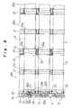
- Fig. 3 shows a battery power source assembly 8 constituted of a left and right pair of battery power source devices 6, 6.
- Each battery power source device 6 is constructed by holding within a holder casing 10 a total of 21 battery modules 9 arranged in parallel in three rows transversely and seven rows vertically, each module being constituted by connecting electrically and mechanically in series a row of six single cells 7.
- series connection is effected between single cells 7 using spot welds S, by means of metal connecting rings 50.
- square nuts 11 provided with seats 11a are connected to single cells 7 at the plus electrode end using spot welding by means of connecting rings 50, at the plus electrode end of battery module 9.
- hexagonal nuts 12 are connected to single cells 7 at the minus electrode end using spot welding by means of connecting rings 50 at the minus electrode end of battery module 9.
- Insulating rings 13a, 13b made of resin are interposed at the connecting parts in order to prevent short circuiting of the plus electrode and minus electrode in the same single cell. These insulating rings 13a, 13b are made of two types of different external diameter; of the total of six insulating rings 13a, 13b, two of these, indicated by 13b, have the larger external diameter.
- a PTC (Positive Temperature Coefficient) sensor 14 is connected to the side circumferential face of each single cell 7.
- This PTC sensor is a temperature sensor in which abnormality is detected by an abrupt increase of electrical resistance which occurs when the temperature of a single cell 7 rises due to some internal abnormality.
- a sensor may be employed whose electrical resistance rises abruptly when a temperature of 80°C is reached.
- a PTC sensor may also be called a "poly sensor”. Sensors other than PTC sensors may of course be used for such temperature sensor 14.
- Six PTC sensors 14 are connected in series by connecting wire 15, and a terminal element 16 consisting of bendable metal plate is mounted at both ends of these. The two terminal elements 16, 16 are arranged so as to project from both ends of battery module 9.
- outer peripheral surface of battery module 9 is covered by means of an outer tube 17 made of resin such as polyvinyl chloride having electrical insulation and heat shrinkage properties.
- PTC sensor 14 and its connecting wire 15 are protected by single cell 7 and outer tube 17.
- Square nut 11 constituting the plus electrode, hexagonal nut 12 constituting the minus electrode and the two terminal elements 16, 16 are exposed with respect to outer tube 17.
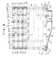
- holder casing 10 is chiefly constituted by main casing body 18, first end plate 19, second end plate 20, three cooling fin plates 21, 21, 21 and two anti-vibration rubber sheets 22, 22.
- Main casing body 18 consists of a unitary resin moulding formed in the shape of a cuboidal box whose upper and lower faces are open.
- the space 26 formed within the two end walls 23, 23 and two side walls 24, 24 constituting four perpendicular walls is practically equally divided into three spaces 26a, 26b, 26c by two partitions 25, 25 parallel to the two end walls 23, 23.
- Cooling fin plates 21 are inserted from above so as to be positioned in the middle respectively of first partitioned space 26a on the side nearest the second end plate 20, second partitioned space 26b in the middle, and third partitioned space 26c on the side nearest first end plate 19, being arranged parallel to the two end walls 23, 23 and fixed to main casing body 18.
- a total of 21 insertion apertures 23a, 25a, 21a in three transverse (horizontal direction) and seven vertical (vertical direction) rows for insertion of battery modules 9 are arranged in the same corresponding positions in end walls 23, 23, partitions 25, 25 and cooling fin plates 21, 21, 21.
- the insertion apertures 23a, 25a, 21a in the three transverse rows and seven vertical rows are arranged with equal pitch in the transverse and vertical directions and are formed so as to have larger diameter than the external diameter of battery modules 9.
- First end plate 19 is screw-fixed to end wall 23 at one end of main casing body 18, by utilising screw holes 70 at its four corners.
- 27 is a frame part formed at the periphery of end wall 23 of main casing body 18 so as to receive first end plate 19 fitting within it.
- Second end plate 20 is releasably held on end wall 23 at the other end of main casing body 18. Specifically, second end plate 20 is held fitted in a movable condition on a frame 27 formed at the other end of main casing body 18.
- first end plate 19 is constituted by a resin plate and has a bus bar 28 embedded and fixed in this resin plate by insertion moulding.
- On the inside face 29 of the resin plate there are provided square-shaped holding recesses 30a for holding, fitted therein, the square nut 11 constituting the plus electrode terminal of a battery module 9 and hexagonal-shaped holding recesses 30b for holding, fitted therein, the hexagonal nut 12 constituting the minus electrode terminal of a battery module 9.
- These holding recesses 30a, 30b are provided in corresponding positions to insertion apertures 23a, 25a, 21a and are provided in a total number of 21 in three transverse rows and seven vertical rows.
- holding recess 30a, 30b are arranged alternately in a relationship such that, of adjacent recesses, one of these is a plus-side square-shaped holding recess 30a while the other is a minus-side hexagonal-shaped holding recess 30b.
- Holding recesses 30a, 30b are formed of such shape that nuts 11, 12 of the electrode terminals of battery module 9 fit thereinto, so square nut 11 can only be held in square holding recess 30a and the possibility of its being accidentally held in hexagonal holding recess 30b can be forestalled.
- a total of 21 locking recesses 32a, 32b are formed in the outside face 31 of first end plate 19 in positions corresponding to holding recesses 30a, 30b.
- the shapes of these locking recesses 32a, 32b are of two types, namely, square and hexagonal: square locking recesses 32a are of exactly the same shape as square holding recesses 30a described above and hexagonal locking recesses 32b are of exactly the same shape as hexagonal holding recesses 30b described above.
- a hexagonal locking recess 32b is provided behind square holding recess 30a and a square locking recess 32a is provided behind hexagonal holding recess 30b, respectively.
- first end plate 19 is assembled into main casing body 18 in a condition as described above but, when a right-side battery power source device 6 is employed, first end plate 19 is assembled into main casing body 18 with recesses corresponding to locking recesses 32a, 32b reversed as between the inside and outside faces so that they are employed as holding recesses 30a, 30b.
- Metal bus bars 28 that effect electrical connection between the terminals of battery modules 9 are embedded and fixed by insertion moulding such as to be positioned in the middle in the thickness direction of the resin plate of first end plate 19. Bus bars 28 are exposed to the outside at portions surrounded by holding recesses 30a, 30b and locking recesses 32a, 32b.
- Through-holes 33 are provided in the middle of such exposed portions.
- hexagonal nut 12 constituting the minus electrode of battery module 9 is held fitted in, without any possibility of confusion, in the minus-side hexagonal holding recess 30b, so the minus electrode of battery module 9 is reliably connected to the minus portion of a bus bar 28. Also, since nuts 11 and 12 are prevented from rotation by holding recesses 30a, 30b, the locking operation by means of bolt 34 can proceed smoothly.
- second end plate 20 is constituted of a resin plate and a bus bar 28 is embedded and fixed in the resin plate by insertion moulding. Its inside face 29 is provided with holding recesses 30a, 30b while its outside face 31 is provided with locking recesses 32a, 32b.
- nuts 11, 12 at the ends of battery modules 9 are electrically and mechanically locked to bus bar 28 by means of bolts 34.
- Hexagonal holding recesses 30b of second end plate 20 are of course arranged in locations facing square holding recesses 30a of first end plate 19, while square holding recesses 30a of second end plate 20 are arranged in locations facing hexagonal holding recesses 30b of first end plate 19.
- the 21 battery modules 9 which are arranged in parallel in battery power source devices 6 are electrically connected in series by means of bus bars 28 of first end plate 19 and bus bars 28 of second end plate 20.
- the bus bars 28 embedded and fixed in first end plate 19 are eleven in number, and are indicated in Fig. 10 by S1, S3, S5, S7, S9, S11, S13, S15, S17, S19, and S21.
- the bus bars 28 that are embedded in fixed in second end plate 20 are eleven in number are indicated in Fig. 13 by S2, S4, S6, S8, S10, S12, S14, S16, S18, S20, and S22.
- the connection relationship of these with battery modules 9 is shown in Fig. 15.
- bus bars indicated by S1 and S22 should be called a minus terminal bar in the case of the former or a plus terminal bar in the case of the latter, rather than bus bars. Although this is not included in the concept of a bus bar according to the present invention, for convenience in description of this embodiment, they are called bus bars and will be described below.
- the bus bars indicated by S2 ⁇ S21 have a contact with the plus electrode and a contact with the minus electrode of the battery modules 9 that are electrically adjacent in series; thus these adjacent battery modules 9 are electrically connected in series. For example as shown in Fig.
- the bus bar indicated by S2 is provided with a plus electrode contact 2a and a minus electrode contact 2b, while the bus bar indicated by S21 is equipped with a plus electrode contact 21a and minus electrode contact 21b.
- the contact indicated by 1ab in Fig. 15 is the minus terminal for the entire battery power source assembly 8. To this is connected connecting end ring 35a (see Fig. 7) of motive power cable 35 connected to the battery driven motor. Also, the contact indicated by 22ab in Fig. 15 is the plus terminal of one of the battery power source devices 6. To this is connected the connecting end of a connection cable 36 (see Fig. 3) connected to the minus terminal of the other battery power source device 6. The voltage between the two contacts 1ab and 22ab is about 125 V. Connecting cable 36 has flexibility so that electrical connection between the two battery power source devices 6, 6 can be reliably performed even if there is movement of second end plate 20 due to thermal expansion/contraction of battery modules 9.
- leads 37 for measurement of the voltage between the terminals of the units of the two battery modules 9, 9 are embedded in a resin plate by insertion moulding.
- leads 37 are respectively connected to bus bars 28 indicated by S1, S3, S5, S7, S9, S11, S13, S15, S17, S19, and S21 such that the voltage V 1-3 between bus bars S1 and S3 for example or the voltage V 19-21 between bus bars S19 and S21 can be measured.
- Voltage V 1-3 indicates the voltage between the two battery modules 9, 9 that are electrically connected in series between bus bar S1 and bus bar S3, in other words the voltage across the twelve single cells 7 while the voltages V 3-5 , V 5-7 , ..., V 19-21 shown in Fig. 15 likewise indicate the voltage between the two battery modules 9, 9.
- Leads 37 are arranged as shown in Fig. 10 within the resin plate of first end plate 19 and are collected into a single location on one side of first end plate 19, where they are brought together and extracted to the outside. As shown in Fig. 7, leads 37 are fixed to a resin sheet 38 in the form of a tape and lead to a voltage measurement unit.
- leads 37 is only provided in first end plate 19, while no wiring at all is provided in second end plate 20.
- a holding element 43 for connecting terminal element 16 of connecting wire 15 whereby six of the aforesaid PTC sensors 14 are connected in series is fixed to the resin plate by insertion moulding in first end plate 19.
- Holding element 43 is provided with a screw hole 45 exposed at a through-hole aperture 44 provided in first end plate 19. Then, after inserting terminal element 16 into through-hole aperture 44, it is bent and, next, using a screw 46, as shown in Fig. 12, terminal element 16 is electrically and mechanically connected to holding element 43.
- Holding element 43 is provided at both ends with two screw holes 45, 45 and acts as a bus bar effecting electrical connection of terminal elements 16, 16 of adjacent connecting wires 15.
- a holding element indicated by P in Fig. 10 and Fig. 16 has only a single screw hole 45 and acts solely as the minus terminal.
- a holding element 43 as described above is also fixed in second end plate 20 in the resin plate by insert forming as shown in Fig. 13.
- the holding element 43 of this second end plate 20 is also provided with two screw holes 45, 45 and acts as a bus bar.
- the holding element indicated by Q in Fig. 13 and Fig. 16 has only a single screw hole 45 and serves solely as a plus terminal.
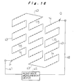
- Fig. 16 shows a condition in which PTC sensors 14 connected to all 126 single cells 7 that are provided in battery power source device 6 are connected electrically in series by means of holding elements 43 of first end plate 19 and second end plate 20. Since this is the same as the case where battery modules 9 shown in Fig. 15 are connected electrically in series using bus bars 28, a detailed description is omitted.
- Respective external lead-out wires 47, 48 are connected (see Fig. 3) to holding element 43 constituting the minus terminal and indicated by P and to holding element 43 constituting the plus terminal and indicated by Q and are connected to a resistance measurement device 49.
- a resistance measurement device 49 As a result of the enormous increase in resistance of PTC sensor 14 connected to a single cell 7 when there is an abnormal rise in temperature in one of the aforementioned 126 single cells 7, this abnormality can be detected by resistance measurement device 49. Consequently, by means of a straightforward construction in which the number of external lead-out wires 47, 48 is a minimum of two, it is possible to detect abnormal rise in temperature of all the single cells 7 of battery power source 6. A like arrangement is provided in the other battery power source device 6 constituting battery power source assembly 8.
- both ends of 21 battery modules 9 are fixed and supported in the first end plate 19 and second end plate 20 in the holder casing 10 of battery power source device 6. Also, battery modules 9 are supported in insertion holes 25a of the partitions 25, 25 by means of anti-vibration rings 51, 51 at two locations at positions about 1/3 of their lengths respectively from both ends in their longitudinal directions.
- anti-vibration rings 51 are integrally formed on anti-vibration rubber sheet 22 in such a way that they project from its front surface.
- Anti-vibration rubber sheet 22, which is provided with 21 anti-vibration rings 51 is mounted along one face of partition 25 by pressing in all the anti-vibration rings 51 into insertion holes 25a of partition 25.
- holder casing 10 is partitioned into three spaces by means of two partitions 25, 25. Specifically, in order from the second end plate 20 to the first end plate 19, these are first partitioned space 26a, second partitioned space 26b, and third partitioned space 26c. In the middle of each partitioned space 26a, 26b, 26c, a cooling adjustment fin plate 21 is inserted from above and fixed to main casing body 18. Fig. 8 and Fig.
- cooling adjustment fins 52 (including first stage fin 52a, second stage fin 52b, third stage fin 52c, fourth stage fin 52d, fifth stage fin 52e, sixth stage fin 52f, seventh stage fin 52g, and eighth stage fin 52h) that are formed on cooling adjustment fin plate 21 and battery modules 9 that are freely inserted in insertion holes 21a of cooling adjustment fin plate 21.
- means are required in battery power source device 6 for cooling the batteries in order to prevent abnormal rise in temperature produced by evolution of heat by the batteries.
- the lower aperture of holder casing 10 constitutes an air introduction section 53 while its upper aperture constitutes an air extraction section 54. Cooling of the battery modules 9, which are arranged horizontally in seven vertical rows and three transverse rows is performed by means of an air current flowing from the bottom (upstream side) to the top (downstream side).
- cooling adjustment fins 52 project in both directions from the main plate body 21 of cooling adjustment fin plate 21 and extend to a position adjacent partitions 25, 25 so as to adjust the direction of flow and the flow rate of the air current.
- a first stage fin 52a is provided that is arcuate in cross-section about the bottom side of three respective insertion holes 21a I (the seven insertion holes from the first stage to the seventh stage are respectively indicated by I ⁇ VII in Fig. 17) of the lowest stage (also called the first stage), as shown in Fig. 17, so as to severely reduce the ratio of the amount of air directly incident on to first-stage battery module 9.
- a second-stage fin 52b, third stage fin 52c, and fourth stage fin 52d of flat H-shape with an interruption section in cross-section are provided in vertically intermediate positions between corresponding insertion holes in, respectively, first stage three insertion holes I and the second stage three insertion holes II thereabove, second stage three insertion holes II and the third stage three insertion holes III thereabove, and third stage three insertion holes III and the fourth stage three insertion holes IV thereabove.
- Second stage fin 52b is formed with interrupting sections t, t on both sides of the portion of H-shaped cross-section; third stage fin 52c is formed with an interrupting portion t 1 in the middle of the portion of H-shaped cross-section; and fourth stage fin 52d is formed with an interrupting portion t 2 of greater width in the middle of the portion of H-shaped cross-section.
- fifth stage fins 52e consisting of four fins arranged next to each other transversely and consisting of two fins of vertically elongate elliptical cross-sectional shape (those shown in Fig. 17 are hollow in cross-section in order to reduce weight, but fins which are not hollow could be employed) and two fins of vertically elongate semi-elliptical cross-section (which could be hollow or not).
- the two fins of vertically elongate elliptical cross-section that are positioned in the middle are arranged at the centre-points of the four insertion holes IV, IV, V, V in the vertical and horizontal directions of their respective peripheries, while the two fins of vertically elongate semi-elliptical cross-section that are positioned at both ends are located on the outside vertically in the middle of corresponding vertical insertion apertures IV and V, so as to make contact with the side edge of main plate and body section 21b.
- stage fins 52f and seven stage fins 52g consisting of four fins in the same relative positions and of practically the same shape as fins 52e of the fifth stage.
- eighth stage fins 52h consisting of four fins in the same positional relationship as seventh stage fins 52g, being fins of a shape wherein the upper half of the fins of seventh stage fins 52g is omitted.
- the cross-sectional area of the fins of sixth stage fins 52f is larger than the cross-sectional area of the fins of fifth stage fins 52e and the cross-sectional areas of the fins of seventh stage fins 52g is larger than the cross-sectional area of the fins of sixth stage fins 52f.
- the flow path of the air current formed between battery module 9 and cooling adjustment fins 52 is throttled as one goes further in the upwards direction, so that the flow rate of air flowing through the peripheral region of battery module 9 of the fifth stage is larger than the flow rate of air flowing through the peripheral region of battery module 9 of the fourth stage, the flow rate of air flowing through the peripheral region of sixth stage battery module 9 is increased from the flow rate of air flowing through the peripheral region of the battery module 9 of the fifth stage, and the flow rate of air flowing through the peripheral region of the seventh stage battery module is greater than the flow rate of air flowing through the peripheral region of battery module 9 of the sixth stage.
- This utilises the fact that, when the flow rate of an air current increases, its cooling effect increases in proportion to the square root.
- the air cooling structure of battery modules 9 was described above taking as example the case of second partitioned space 26b; however, the air cooling structure in the other, namely, the first partitioned space 26a and third partitioned space 26c is constructed in the same way.
- the air cooling structure in the other namely, the first partitioned space 26a and third partitioned space 26c is constructed in the same way.
- the battery modules 9 belonging to the lower-stage side groups in the case shown in Fig.
- the air current is throttled, so as to raise the flow speed of the air current around battery modules 9.
- these gaps are made progressively narrower going towards the upper stages (fifth stage, sixth stage and seventh stage) to raise the flow rate of the air current around battery modules 9 so as to compensate for the loss of cooling effect of the air as it is gradually heated up as it rises: thus practically uniform cooling of the battery modules 9 in each stage (fifth stage ⁇ seventh stage) can be achieved.
- the batteries used in this embodiment are nickel-hydrogen secondary cells, it is necessary to devise safety measures in respect of hydrogen leakage in the event of abnormality from the battery cans.
- the air is fed into battery power source device 6 by pressure feed by a fan 5 equipped with a sirocco fan.
- a fan 5 equipped with a sirocco fan.
- it is in particular vital to give consideration to ensuring that hydrogen cannot be fed into the vicinity of fan 5 and the interior of motor 57 that drives this and/or their vicinity. Accordingly, in this embodiment, as shown in Fig. 8, Fig. 17 and Fig.
- fan 5 and motor 57 are arranged to the side and underneath holder casing 10 and fan aperture 58 is arranged below holder casing 10, so that air that is pressure-fed from fan 5 passes through air supply chamber 59 formed below outer casing 4, and reaches air introduction section 53 at the bottom end of holder casing 10, and then cools battery modules 9 by flowing through holder casing 10 from the bottom to the top, then issues from air extraction section 54 of holder casing 10, after which it passes through air discharge chamber 60 formed above outer casing 4 and is discharged to the outside of outer casing 4 from a discharge port 61 formed in the upper side end of outer casing 4.
- Fig. 18 shows a construction in which cooling air is pressure-fed to left and right battery power source devices 6, 6 by a single fan 5.
- Fan 5 is equipped with a pair of left and right sirocco fans and fan apertures 58, 58; it extracts air within the vehicle from air extraction port 62 and feeds air uniformly from the pair of fan apertures 58, 58 into left and right air supply chambers 59, 59.
- Air supply chambers 59 are constituted by a space enclosed by a bottom sheet part 4a of outer casing 4, the front wall 4b that stands erect in a front position in Fig. 18 of bottom sheet 4a, and the bottom face of holder casing 10.
- At an inlet 63 facing fan aperture 58 there are provided a plurality of curved flow alignment guides 64a, 64b, 64c erected on bottom sheet 4a for guiding air from fan aperture 58 inwards and sideways.
- Inlet 63 is arranged in the middle in the width direction of outer casing 4, being arranged so as to be positioned below first partitioned space 26a of holder casing 10.
- Bottom sheet 4a is formed so that, within air supply chamber 59, it has a slope 65 going gradually upwards towards the outside i.e. towards second partitioned space 26b and third partitioned space 26c, and has a slope 66 going gradually upwards towards the inside.
- An air current direction guide 67 of small height that leads the air upwards is provided at a position on slope 65 below the boundary of second partitioned space 26b and third partitioned space 26c (see Fig. 8).
- the air that is extracted from inlet 63 is fed through two air passages formed in each space between the three flow alignment guides 64a, 64b and 64c into the inside and into second and third partitioned spaces 26b, 26c, while part of it is fed into first partitioned space 26a.
- an air current direction guide 68 that directs the air upwards in the vicinity of the inlet to the air passage nearest second end plate 20.
- Air current direction guide 67 is provided in order to ensure that there is no insufficiency in the amount of air that is fed into second partitioned space 26b at this point. The air that is led to below third partitioned space 26c is then led into third partitioned space 26c.
- air current direction guide 67 such as to make the amount of air that is directed into second partitioned space 26b rather larger than the amount of air that is directed into the other partitioned spaces 26a, 26c.
- outer casing 4 is provided with a holder casing mounting seat 71 on its bottom sheet 4a and the left and right holder casings 10, 10 are mounted and fixed in a foot portion 72 thereof by means of bolts and nuts 73. Also, a flange 74 is provided mounted on the main automobile body at the periphery of outer casing 4.
- a safety plug 75 in order to cut off temporarily this series connection.
- a bypass may be provided whereby the locations indicated by 17a and 17b and an openable safety plug 75 are connected by leads 76, 77 by for example severing S17 bus bars 28 at a location indicted by N in subsequent processing, after exposing these at an aperture provided in first end plate 19.
- the support strength and rigidity of the battery modules can be enormously improved and a battery power source device and end plates for use therein can be provided whereby the battery modules can be assembled in the holder casing in a simple manner and without any possibility of their being wrongly inserted.
- the problem of occurrence of twisting between the single cells constituting the battery modules on locking the battery modules to the bus bars can be solved and the benefit can be obtained that voltage detection of the battery modules and/or detection of abnormal rise in temperature of the single cells can be achieved efficiently by means of a straightforward construction.
- uniform cooling can be performed of the battery modules which are arranged parallel to each other in large numbers in the holder casing, and cooling that is uniform as between the single cells constituting the battery modules can also be achieved.
- the problem that the cooling effect of the cooling air is lowered because of its increased temperature on the downstream side compared with the upstream side is solved, thereby making it possible to effect uniform cooling of the battery modules whether they are on the upstream side or downstream side.
- efficient utilisation of the air current can be achieved by preventing over-cooling of the battery modules on the upstream side.
- cooling of a battery power source employing nickel-hydrogen secondary cells can be performed whilst maintaining safety in regard to hydrogen.
- cooling of a battery power source assembly comprising a pair of battery power source devices can be performed in a uniform manner for all the battery modules by using only a single pressure-feed fan.
Priority Applications (4)
| Application Number | Priority Date | Filing Date | Title |
|---|---|---|---|
| EP20000107969 EP1030390B1 (de) | 1997-03-24 | 1998-03-20 | Stromversorgungseinheit enthaltend eine modulare Batterie |
| EP20030016666 EP1376734A3 (de) | 1997-03-24 | 1998-03-20 | Kühlvorrichtung für Batterie Energiequelle |
| EP20030016665 EP1376733A3 (de) | 1997-03-24 | 1998-03-20 | Kühlvorrichtung für Batterie Energiequelle |
| EP20000107968 EP1030389B1 (de) | 1997-03-24 | 1998-03-20 | Batteriegehäuse mit integrierten Kabeln zur Spannungsmessung |
Applications Claiming Priority (6)
| Application Number | Priority Date | Filing Date | Title |
|---|---|---|---|
| JP69956/97 | 1997-03-24 | ||
| JP6995797 | 1997-03-24 | ||
| JP69957/97 | 1997-03-24 | ||
| JP6995697 | 1997-03-24 | ||
| JP06995797A JP3829396B2 (ja) | 1997-03-24 | 1997-03-24 | 電池電源の冷却装置 |
| JP06995697A JP3774977B2 (ja) | 1997-03-24 | 1997-03-24 | 電池電源装置とこれに用いるエンドプレート |
Related Child Applications (3)
| Application Number | Title | Priority Date | Filing Date |
|---|---|---|---|
| EP20000107969 Division EP1030390B1 (de) | 1997-03-24 | 1998-03-20 | Stromversorgungseinheit enthaltend eine modulare Batterie |
| EP20030016665 Division EP1376733A3 (de) | 1997-03-24 | 1998-03-20 | Kühlvorrichtung für Batterie Energiequelle |
| EP20000107968 Division EP1030389B1 (de) | 1997-03-24 | 1998-03-20 | Batteriegehäuse mit integrierten Kabeln zur Spannungsmessung |
Publications (3)
| Publication Number | Publication Date |
|---|---|
| EP0892450A2 true EP0892450A2 (de) | 1999-01-20 |
| EP0892450A3 EP0892450A3 (de) | 1999-02-03 |
| EP0892450B1 EP0892450B1 (de) | 2004-05-12 |
Family
ID=26411133
Family Applications (4)
| Application Number | Title | Priority Date | Filing Date |
|---|---|---|---|
| EP20000107969 Expired - Lifetime EP1030390B1 (de) | 1997-03-24 | 1998-03-20 | Stromversorgungseinheit enthaltend eine modulare Batterie |
| EP19980302116 Expired - Lifetime EP0892450B1 (de) | 1997-03-24 | 1998-03-20 | Stromversorgungsteil enthaltend modulare Batterie |
| EP20000107968 Expired - Lifetime EP1030389B1 (de) | 1997-03-24 | 1998-03-20 | Batteriegehäuse mit integrierten Kabeln zur Spannungsmessung |
| EP20030016666 Withdrawn EP1376734A3 (de) | 1997-03-24 | 1998-03-20 | Kühlvorrichtung für Batterie Energiequelle |
Family Applications Before (1)
| Application Number | Title | Priority Date | Filing Date |
|---|---|---|---|
| EP20000107969 Expired - Lifetime EP1030390B1 (de) | 1997-03-24 | 1998-03-20 | Stromversorgungseinheit enthaltend eine modulare Batterie |
Family Applications After (2)
| Application Number | Title | Priority Date | Filing Date |
|---|---|---|---|
| EP20000107968 Expired - Lifetime EP1030389B1 (de) | 1997-03-24 | 1998-03-20 | Batteriegehäuse mit integrierten Kabeln zur Spannungsmessung |
| EP20030016666 Withdrawn EP1376734A3 (de) | 1997-03-24 | 1998-03-20 | Kühlvorrichtung für Batterie Energiequelle |
Country Status (6)
| Country | Link |
|---|---|
| US (3) | US6111387A (de) |
| EP (4) | EP1030390B1 (de) |
| JP (1) | JP4487967B2 (de) |
| KR (3) | KR100360968B1 (de) |
| CN (5) | CN1226153C (de) |
| DE (3) | DE69823745T2 (de) |
Cited By (25)
| Publication number | Priority date | Publication date | Assignee | Title |
|---|---|---|---|---|
| EP0986114A1 (de) * | 1998-09-09 | 2000-03-15 | Yazaki Corporation | Batterie-Verbindungsplatte |
| FR2789228A1 (fr) * | 1999-01-28 | 2000-08-04 | Sanyo Electric Co | Alimentation electrique a plusieurs modules, notamment pour automobiles electriques |
| EP1030388A1 (de) * | 1999-02-15 | 2000-08-23 | Sony Corporation | Batterieanordnung für ein Fahrzeug |
| EP1030387A1 (de) * | 1999-02-15 | 2000-08-23 | Sony Corporation | Batterieanordnung für ein Fahrzeug |
| FR2790182A1 (fr) * | 1999-02-19 | 2000-08-25 | Sanyo Electric Co | Source d'alimentation electrique |
| DE19847190C2 (de) * | 1997-10-13 | 2000-11-09 | Yazaki Corp | Verbindungsplatte für einen Batteriehalter und Verfahren zur Herstellung derselben |
| US6152776A (en) * | 1997-10-13 | 2000-11-28 | Yazaki Corporation | Connecting plate for a battery holder |
| EP1058332A2 (de) * | 1999-05-31 | 2000-12-06 | Sanyo Electric Co., Ltd. | Stromversorgungseinheit |
| US6346011B1 (en) | 1998-10-09 | 2002-02-12 | Yazaki Corporation | Battery-connecting plate, method of producing same and wire protector |
| DE10064648C2 (de) * | 1999-12-28 | 2003-09-18 | Honda Motor Co Ltd | Batterieeinheit |
| EP1333511A3 (de) * | 2002-01-31 | 2004-03-10 | Sanyo Electric Co., Ltd. | Energiequelle-Gerät |
| DE10003247B4 (de) * | 1999-01-29 | 2005-02-24 | Sanyo Electric Co., Ltd., Moriguchi | Stromquelle, versehen mit wiederaufladbaren Batterien |
| WO2007027603A2 (en) * | 2005-09-02 | 2007-03-08 | Alcoa Fujikura Ltd. | Integrated module connection for hev battery |
| GB2452820A (en) * | 2007-09-14 | 2009-03-18 | Ford Global Tech Llc | A battery connector |
| WO2009121613A1 (en) * | 2008-04-03 | 2009-10-08 | Amberjac Projects Ltd | Improvement in or relating to battery systems |
| EP2357688A1 (de) * | 2008-12-10 | 2011-08-17 | Panasonic Corporation | Batteriemodul und batteriemodulbaugruppe damit |
| EP2426775A1 (de) * | 2009-04-28 | 2012-03-07 | Hitachi, Ltd. | Elektrizitätsspeichermodul und elektrizitätsspeichervorrichtung damit |
| EP2741344A1 (de) * | 2011-09-16 | 2014-06-11 | Japan Aviation Electronics Industry, Limited | Elektrische speichervorrichtung |
| EP2810805A4 (de) * | 2012-01-30 | 2016-03-30 | Toyota Motor Co Ltd | Fahrzeug |
| WO2016128180A1 (de) * | 2015-02-13 | 2016-08-18 | Siemens Aktiengesellschaft | Elektrischer energiespeicher |
| EP3176850A4 (de) * | 2014-07-30 | 2017-08-23 | AutoNetworks Technologies, Ltd. | Leistungsspeichermodul |
| WO2018065172A1 (de) * | 2016-10-05 | 2018-04-12 | Bayerische Motoren Werke Aktiengesellschaft | Elektrischer energiespeicher mit energiespeicherzellen deren seitenflächen mit einem muster versehen sind |
| GB2561359A (en) * | 2017-04-10 | 2018-10-17 | Detroit Electric Ev Ltd | Sensor arrangement for battery unit of electrical vehicle |
| US11165110B2 (en) | 2016-10-05 | 2021-11-02 | Bayerische Motoren Werke Aktiengesellschaft | Stored electrical energy source having cooling plates arranged between the cells for emergency cooling |
| US11183719B2 (en) | 2016-10-05 | 2021-11-23 | Bayerische Motoren Werke Aktiengesellschaft | Stored electrical energy source having an emergency cooling device |
Families Citing this family (164)
| Publication number | Priority date | Publication date | Assignee | Title |
|---|---|---|---|---|
| JP4122553B2 (ja) * | 1997-11-21 | 2008-07-23 | 豊田合成株式会社 | 棒状体支持箱 |
| JP4231127B2 (ja) * | 1998-09-03 | 2009-02-25 | パナソニック株式会社 | 集積電池の温度管理方法及びその装置 |
| FR2790870B1 (fr) * | 1999-03-11 | 2001-06-01 | Oldham France Sa | Coffre pour ensemble de batteries d'accumulateurs electriques |
| JP4425369B2 (ja) * | 1999-04-23 | 2010-03-03 | 富士重工業株式会社 | バッテリ電源装置 |
| EP1258070A2 (de) * | 2000-02-18 | 2002-11-20 | Liebert Corporation | Modulare unterbrechungsfreie stromversorgung |
| JP4046463B2 (ja) * | 2000-08-03 | 2008-02-13 | 三洋電機株式会社 | 電源装置 |
| JP4717990B2 (ja) * | 2000-09-13 | 2011-07-06 | パナソニック株式会社 | 電池パック |
| JP4118014B2 (ja) * | 2000-10-31 | 2008-07-16 | 三洋電機株式会社 | 電源装置 |
| JP3805664B2 (ja) | 2001-11-01 | 2006-08-02 | 株式会社マキタ | 電池パック |
| US7014949B2 (en) * | 2001-12-28 | 2006-03-21 | Kabushiki Kaisha Toshiba | Battery pack and rechargeable vacuum cleaner |
| US6631071B2 (en) * | 2002-01-16 | 2003-10-07 | Matsushita Electric Industrial Co., Ltd. | Capacitor module |
| KR20100088625A (ko) * | 2002-02-19 | 2010-08-09 | 쓰리엠 이노베이티브 프로퍼티즈 컴파니 | 고에너지 전기 화학 전지를 위한 온도 제어 장치 및 방법 |
| US6812656B2 (en) * | 2002-02-27 | 2004-11-02 | Railpower Technologies Corp. | Sequenced pulse width modulation method and apparatus for controlling and powering a plurality of direct current motors |
| US6677728B2 (en) | 2002-04-12 | 2004-01-13 | Honda Giken Kogyo Kabushiki Kaisha | Battery box and battery holder having detachable ring-shaped members |
| JP4243334B2 (ja) * | 2002-06-11 | 2009-03-25 | パナソニック株式会社 | 組電池 |
| JP4170714B2 (ja) * | 2002-09-20 | 2008-10-22 | 松下電器産業株式会社 | 組電池 |
| ATE382960T1 (de) * | 2002-10-25 | 2008-01-15 | William E M Jones | Elektrische batterie mit autonomen nachfüllungs- und säuremischsystemen |
| CA2411132A1 (en) * | 2002-11-05 | 2004-05-05 | Railpower Technologies Corp. | Direct turbogenerator |
| US7189473B2 (en) * | 2003-06-03 | 2007-03-13 | Eastway Fair Company Limited | Battery venting system |
| WO2005030550A1 (en) | 2003-08-26 | 2005-04-07 | Railpower Technologies Corp. | A method for monitoring and controlling locomotives |
| US6932651B2 (en) * | 2003-09-16 | 2005-08-23 | Honda Motor Co., Ltd. | Connecting structure for electric cells |
| US20050064785A1 (en) * | 2003-09-16 | 2005-03-24 | New Bright Industrial Co., Ltd. | High performance rechargeable battery pack for toy vehicles |
| US20050112457A1 (en) * | 2003-11-25 | 2005-05-26 | Dell Products L.P. | Information handling system including battery assembly having multiple separable subassemblies |
| KR100556101B1 (ko) * | 2003-12-16 | 2006-03-03 | 주식회사 엘지화학 | 이차전지 모듈 |
| WO2005069408A1 (ja) * | 2004-01-20 | 2005-07-28 | Matsushita Electric Industrial Co., Ltd. | 電池パック |
| US7467830B2 (en) * | 2004-02-17 | 2008-12-23 | Railpower Technologies Corp. | Managing wheel slip in a locomotive |
| US20050279242A1 (en) * | 2004-03-01 | 2005-12-22 | Railpower Technologies Corp. | Cabless hybrid locomotive |
| WO2005086910A2 (en) * | 2004-03-08 | 2005-09-22 | Railpower Technologies Corp. | Hybrid locomotive configuration |
| WO2005097573A2 (en) * | 2004-03-30 | 2005-10-20 | Railpower Technologies Corp. | Emission management for a hybrid locomotive |
| US7507500B2 (en) * | 2004-05-17 | 2009-03-24 | Railpower Technologies Corp. | Design of a large battery pack for a hybrid locomotive |
| US7940016B2 (en) * | 2004-08-09 | 2011-05-10 | Railpower, Llc | Regenerative braking methods for a hybrid locomotive |
| EP1791746A2 (de) * | 2004-08-09 | 2007-06-06 | Railpower Technologies Corp. | Lokomotiventriebstrangarchitektur |
| US7565867B2 (en) * | 2004-09-03 | 2009-07-28 | Frank Wegner Donnelly | Multiple engine locomotive configuration |
| DE102004049298A1 (de) * | 2004-10-09 | 2006-04-13 | Bayerische Motoren Werke Ag | Kraftfahrzeug mit einem Hybridantrieb |
| US7604896B2 (en) * | 2005-03-16 | 2009-10-20 | Ford Global Technologies, Llc | High voltage battery assembly for a motor vehicle |
| JP5190356B2 (ja) * | 2005-03-16 | 2013-04-24 | フォード グローバル テクノロジーズ、リミテッド ライアビリティ カンパニー | 電力供給システム |
| US7967506B2 (en) | 2005-03-16 | 2011-06-28 | Ford Global Technologies, Llc | Power supply temperature sensor and system |
| KR101042132B1 (ko) * | 2005-03-23 | 2011-06-16 | 에스케이이노베이션 주식회사 | 고출력 리튬 2차 전지용 케이스 |
| KR100857019B1 (ko) * | 2005-04-19 | 2008-09-05 | 주식회사 엘지화학 | 기계적 및 전기적 커넥팅 부재 |
| US7518254B2 (en) * | 2005-04-25 | 2009-04-14 | Railpower Technologies Corporation | Multiple prime power source locomotive control |
| JP4694278B2 (ja) * | 2005-04-28 | 2011-06-08 | 本田技研工業株式会社 | バッテリユニット構造 |
| US20060261783A1 (en) * | 2005-05-23 | 2006-11-23 | Paul Gamboa | Electronic battery module (EBM) with bidirectional DC-DC converter |
| EP1900089B1 (de) * | 2005-07-06 | 2018-06-06 | Liebert Corporation | Maximierte batterielaufzeit in einem parallelen usv-system |
| JP4739867B2 (ja) * | 2005-08-31 | 2011-08-03 | 三洋電機株式会社 | 組電池 |
| DE102005056972A1 (de) * | 2005-09-21 | 2007-03-22 | Temic Automotive Electric Motors Gmbh | Energiespeichermodul |
| JP4663464B2 (ja) * | 2005-09-22 | 2011-04-06 | 本田技研工業株式会社 | 蓄電装置搭載車両 |
| KR100903182B1 (ko) * | 2005-09-28 | 2009-06-17 | 주식회사 엘지화학 | 차량용 전지팩의 냉각 시스템 |
| US7661370B2 (en) * | 2005-10-19 | 2010-02-16 | Railpower, Llc | Design of a large low maintenance battery pack for a hybrid locomotive |
| JP4569534B2 (ja) * | 2006-07-19 | 2010-10-27 | トヨタ自動車株式会社 | 組電池 |
| JP4390802B2 (ja) * | 2006-12-15 | 2009-12-24 | トヨタ自動車株式会社 | 車載バッテリ冷却構造 |
| KR100887796B1 (ko) * | 2007-02-26 | 2009-03-09 | 현대자동차주식회사 | 배터리 모듈의 보관장치 |
| US20080225483A1 (en) * | 2007-03-15 | 2008-09-18 | Paccar Inc | Frame mounted modular hybrid cooling system |
| JP4529991B2 (ja) * | 2007-04-03 | 2010-08-25 | 株式会社デンソー | 電池冷却装置 |
| US20080280198A1 (en) * | 2007-05-07 | 2008-11-13 | Ajith Kuttannair Kumar | Battery mechanical packaging |
| US20080288132A1 (en) | 2007-05-16 | 2008-11-20 | General Electric Company | Method of operating vehicle and associated system |
| JP2009021223A (ja) * | 2007-06-11 | 2009-01-29 | Panasonic Corp | 電池パックおよび電池搭載機器 |
| KR100949334B1 (ko) * | 2007-11-12 | 2010-03-26 | 삼성에스디아이 주식회사 | 전지 모듈 |
| DE102007063195B4 (de) * | 2007-12-20 | 2013-08-29 | Daimler Ag | Batterie mit einem Gehäuse und einer Wärmeleitplatte |
| DE102008010839A1 (de) * | 2008-02-23 | 2009-08-27 | Daimler Ag | Batterie mit einer in einem Batteriegehäuse angeordneten Wärmeleitplatte |
| JP4661895B2 (ja) | 2008-04-02 | 2011-03-30 | 株式会社デンソー | 電池冷却装置 |
| EP2278640B1 (de) * | 2008-06-11 | 2017-08-02 | LG Chem, Ltd. | Kühlvervafhren für ein u-förmiges batteriepaket für elektrische fahrräder |
| JP4713615B2 (ja) * | 2008-06-19 | 2011-06-29 | 株式会社日立製作所 | 電池箱およびこれを備える鉄道車両 |
| CN100568612C (zh) | 2008-06-20 | 2009-12-09 | 重庆大学 | 一种混合动力汽车用镍氢电池组的散热系统 |
| JP2010003546A (ja) * | 2008-06-20 | 2010-01-07 | Panasonic Corp | 電池パック |
| US9759495B2 (en) * | 2008-06-30 | 2017-09-12 | Lg Chem, Ltd. | Battery cell assembly having heat exchanger with serpentine flow path |
| US8486552B2 (en) * | 2008-06-30 | 2013-07-16 | Lg Chem, Ltd. | Battery module having cooling manifold with ported screws and method for cooling the battery module |
| DE102008034882A1 (de) * | 2008-07-26 | 2010-01-28 | Daimler Ag | Batterie, insbesondere Fahrzeugbatterie |
| DE102008051085A1 (de) * | 2008-10-09 | 2010-04-15 | Dr.Ing.H.C.F.Porsche Aktiengesellschaft | Batterieanordnung |
| JP5288971B2 (ja) * | 2008-09-27 | 2013-09-11 | 三洋電機株式会社 | バッテリシステム |
| US8153290B2 (en) * | 2008-10-28 | 2012-04-10 | Tesla Motors, Inc. | Heat dissipation for large battery packs |
| JP5436850B2 (ja) * | 2008-12-19 | 2014-03-05 | 株式会社マキタ | 電動工具のバッテリパック |
| JP5442268B2 (ja) * | 2009-01-28 | 2014-03-12 | 三洋電機株式会社 | バッテリシステム |
| US20100295550A1 (en) * | 2009-02-20 | 2010-11-25 | National Semiconductor Corporation | Adaptive energy management terminal for a battery |
| JP5514578B2 (ja) * | 2009-02-24 | 2014-06-04 | 矢崎総業株式会社 | 組電池冷却構造 |
| DE102009012180A1 (de) | 2009-02-27 | 2010-09-02 | Andreas Stihl Ag & Co. Kg | Akkupack für ein Elektrowerkzeug |
| DE102009015351B4 (de) * | 2009-03-28 | 2022-02-03 | Bayerische Motoren Werke Aktiengesellschaft | Kühlanordnung für eine Speicherzellenanordnung für ein Fahrzeug |
| US8403030B2 (en) * | 2009-04-30 | 2013-03-26 | Lg Chem, Ltd. | Cooling manifold |
| US8663829B2 (en) * | 2009-04-30 | 2014-03-04 | Lg Chem, Ltd. | Battery systems, battery modules, and method for cooling a battery module |
| US20100275619A1 (en) * | 2009-04-30 | 2010-11-04 | Lg Chem, Ltd. | Cooling system for a battery system and a method for cooling the battery system |
| DE102009024514A1 (de) | 2009-06-08 | 2010-12-09 | Auto-Kabel Managementgesellschaft Mbh | Trägermatrix für Batteriezellenverbinder |
| KR101065926B1 (ko) * | 2009-07-09 | 2011-09-19 | 삼성에스디아이 주식회사 | 다수의 단위 셀을 구비하는 배터리 팩 |
| JP4815016B2 (ja) * | 2009-07-17 | 2011-11-16 | パナソニック株式会社 | 電池接続部材とそれを用いた電池モジュール |
| FR2948231B1 (fr) * | 2009-07-17 | 2013-01-18 | Peugeot Citroen Automobiles Sa | Vehicule automobile comportant un moteur electrique alimente par un module d'alimentation |
| JP4815026B2 (ja) * | 2009-07-17 | 2011-11-16 | パナソニック株式会社 | 電池モジュールとそれを用いた電池パック |
| US8399118B2 (en) * | 2009-07-29 | 2013-03-19 | Lg Chem, Ltd. | Battery module and method for cooling the battery module |
| KR101143279B1 (ko) * | 2009-08-20 | 2012-05-11 | 주식회사 엘지화학 | 신규한 냉각구조를 가진 전지팩 |
| US8399119B2 (en) * | 2009-08-28 | 2013-03-19 | Lg Chem, Ltd. | Battery module and method for cooling the battery module |
| WO2011024326A1 (ja) * | 2009-08-31 | 2011-03-03 | 本田技研工業株式会社 | 充電器、及び充電器の取付け構造 |
| JP5537111B2 (ja) * | 2009-09-30 | 2014-07-02 | 株式会社東芝 | 二次電池装置 |
| TWI382577B (zh) * | 2009-10-01 | 2013-01-11 | Apogee Power Inc | The battery module setting structure of the generator starting power supply unit |
| JP5433378B2 (ja) * | 2009-10-29 | 2014-03-05 | 株式会社日立製作所 | 電池電源装置 |
| US8124263B2 (en) * | 2010-01-05 | 2012-02-28 | Tesla Motors, Inc. | Corrosion resistant cell mounting well |
| US20110223458A1 (en) * | 2010-03-15 | 2011-09-15 | Electronvault, Inc. | Power Cell Array Receiver |
| US20110223468A1 (en) * | 2010-03-15 | 2011-09-15 | Electronvault, Inc. | Variable Energy System |
| US20110221398A1 (en) * | 2010-03-15 | 2011-09-15 | Electronvault, Inc. | Impedence Balancer |
| JP2011216401A (ja) * | 2010-04-01 | 2011-10-27 | Hitachi Vehicle Energy Ltd | 蓄電モジュールおよび蓄電装置 |
| KR101137365B1 (ko) * | 2010-05-20 | 2012-04-20 | 에스비리모티브 주식회사 | 배터리 팩 |
| GB2481584B (en) * | 2010-06-28 | 2017-06-14 | Energy Control Ltd | A battery assembly |
| US8662153B2 (en) | 2010-10-04 | 2014-03-04 | Lg Chem, Ltd. | Battery cell assembly, heat exchanger, and method for manufacturing the heat exchanger |
| JPWO2012057322A1 (ja) * | 2010-10-30 | 2014-05-12 | 三洋電機株式会社 | 組電池及びこれを用いた車両 |
| JPWO2012093452A1 (ja) * | 2011-01-07 | 2014-06-09 | パナソニック株式会社 | 電池パック |
| SG175219A1 (en) * | 2011-01-24 | 2012-02-28 | Feng Guoan | Power battery pack cooling apparatus |
| KR101243546B1 (ko) * | 2011-03-02 | 2013-03-20 | 로베르트 보쉬 게엠베하 | 이차 전지 및 이를 갖는 배터리 팩 |
| KR101815876B1 (ko) * | 2011-04-28 | 2018-01-08 | 에스케이이노베이션 주식회사 | 과전류 방지장치를 포함한 배터리 팩 |
| GB2492152B (en) * | 2011-06-24 | 2013-05-15 | Energy Control Ltd | Battery assembly structure |
| KR101883915B1 (ko) * | 2011-09-30 | 2018-08-02 | 삼성에스디아이 주식회사 | 지지부재를 포함하는 배터리 모듈 |
| US9763349B2 (en) * | 2011-10-13 | 2017-09-12 | Keihin Corporation | Power supply control apparatus and manufacturing method of power supply control apparatus |
| JP5720544B2 (ja) | 2011-11-23 | 2015-05-20 | 株式会社デンソー | 電池ユニット |
| KR101400085B1 (ko) * | 2011-12-16 | 2014-05-28 | 주식회사 엘지화학 | 절연성 접속부재 및 절연성 체결부재를 구비하는 전지모듈 |
| US9605914B2 (en) | 2012-03-29 | 2017-03-28 | Lg Chem, Ltd. | Battery system and method of assembling the battery system |
| US9379420B2 (en) | 2012-03-29 | 2016-06-28 | Lg Chem, Ltd. | Battery system and method for cooling the battery system |
| US9105950B2 (en) | 2012-03-29 | 2015-08-11 | Lg Chem, Ltd. | Battery system having an evaporative cooling member with a plate portion and a method for cooling the battery system |
| US8852781B2 (en) | 2012-05-19 | 2014-10-07 | Lg Chem, Ltd. | Battery cell assembly and method for manufacturing a cooling fin for the battery cell assembly |
| JP6124121B2 (ja) * | 2012-05-21 | 2017-05-10 | 株式会社Gsユアサ | 蓄電装置の製造方法、スペーサ、及び蓄電装置 |
| WO2013179797A1 (ja) * | 2012-05-31 | 2013-12-05 | 本田技研工業株式会社 | 蓄電モジュールおよび蓄電モジュールの固定構造 |
| US9306199B2 (en) | 2012-08-16 | 2016-04-05 | Lg Chem, Ltd. | Battery module and method for assembling the battery module |
| US20150288039A1 (en) * | 2012-10-30 | 2015-10-08 | Sanyo Electric Co., Ltd. | Battery module |
| US9083066B2 (en) | 2012-11-27 | 2015-07-14 | Lg Chem, Ltd. | Battery system and method for cooling a battery cell assembly |
| JP5672294B2 (ja) * | 2012-11-30 | 2015-02-18 | トヨタ自動車株式会社 | 組電池及び車両 |
| US8852783B2 (en) | 2013-02-13 | 2014-10-07 | Lg Chem, Ltd. | Battery cell assembly and method for manufacturing the battery cell assembly |
| US9738976B2 (en) | 2013-02-27 | 2017-08-22 | Ioxus, Inc. | Energy storage device assembly |
| US9899643B2 (en) | 2013-02-27 | 2018-02-20 | Ioxus, Inc. | Energy storage device assembly |
| US9647292B2 (en) | 2013-04-12 | 2017-05-09 | Lg Chem, Ltd. | Battery cell assembly and method for manufacturing a cooling fin for the battery cell assembly |
| US9892868B2 (en) | 2013-06-21 | 2018-02-13 | Ioxus, Inc. | Energy storage device assembly |
| US9184424B2 (en) | 2013-07-08 | 2015-11-10 | Lg Chem, Ltd. | Battery assembly |
| US10062934B2 (en) * | 2013-07-25 | 2018-08-28 | Johnson Controls Technology Company | Cooling system and method for lithium-ion battery module |
| US9257732B2 (en) | 2013-10-22 | 2016-02-09 | Lg Chem, Ltd. | Battery cell assembly |
| US9444124B2 (en) | 2014-01-23 | 2016-09-13 | Lg Chem, Ltd. | Battery cell assembly and method for coupling a cooling fin to first and second cooling manifolds |
| US10084218B2 (en) | 2014-05-09 | 2018-09-25 | Lg Chem, Ltd. | Battery pack and method of assembling the battery pack |
| US10770762B2 (en) | 2014-05-09 | 2020-09-08 | Lg Chem, Ltd. | Battery module and method of assembling the battery module |
| DE102014219353A1 (de) * | 2014-09-25 | 2016-03-31 | Bayerische Motoren Werke Aktiengesellschaft | Verfahren zur Herstellung eines Kraftfahrzeug-Batteriemoduls sowie Kraftfahrzeug-Batteriemodul |
| DE102014114020A1 (de) * | 2014-09-26 | 2016-03-31 | Obrist Technologies Gmbh | Batteriesystem |
| US9484559B2 (en) | 2014-10-10 | 2016-11-01 | Lg Chem, Ltd. | Battery cell assembly |
| US9412980B2 (en) | 2014-10-17 | 2016-08-09 | Lg Chem, Ltd. | Battery cell assembly |
| US9786894B2 (en) | 2014-11-03 | 2017-10-10 | Lg Chem, Ltd. | Battery pack |
| US9627724B2 (en) | 2014-12-04 | 2017-04-18 | Lg Chem, Ltd. | Battery pack having a cooling plate assembly |
| JP6249991B2 (ja) * | 2015-06-10 | 2017-12-20 | 矢崎総業株式会社 | 配線モジュール |
| US10868287B2 (en) | 2015-07-22 | 2020-12-15 | Ford Global Technologies, Llc | Battery pack endplate |
| DE102016104174A1 (de) | 2016-03-08 | 2017-09-14 | Dr. Ing. H.C. F. Porsche Aktiengesellschaft | Modul für eine Traktionsbatterie und entsprechende Traktionsbatterie |
| US10910611B2 (en) * | 2016-06-29 | 2021-02-02 | Panasonic Intellectual Property Management Co., Ltd. | Battery block and battery module |
| CN106129289B (zh) * | 2016-07-21 | 2019-03-12 | 北京新能源汽车股份有限公司 | 动力电池和具有其的汽车 |
| JP6524051B2 (ja) * | 2016-12-09 | 2019-06-05 | 矢崎総業株式会社 | 導体の接続構造および導電モジュール |
| JP6581958B2 (ja) | 2016-12-09 | 2019-09-25 | 矢崎総業株式会社 | 電圧検出構造および電圧検出モジュール |
| DE202017105488U1 (de) * | 2017-07-18 | 2018-10-24 | Mahle International Gmbh | Batteriezellenanordnung |
| DE102017213554A1 (de) * | 2017-08-04 | 2019-02-07 | Mahle International Gmbh | Batteriekasten für eine Traktionsbatterie |
| JP6691083B2 (ja) * | 2017-08-30 | 2020-04-28 | 矢崎総業株式会社 | バスバ及びバスバモジュール並びに電池パック |
| JP6470804B1 (ja) * | 2017-08-31 | 2019-02-13 | 株式会社ソフトエナジーコントロールズ | コンタクト機能付きマルチチャンネル充放電電源 |
| US10816572B2 (en) * | 2018-01-12 | 2020-10-27 | Rohde & Schwarz Gmbh & Co. Kg | Radio frequency measuring device module and radio frequency measuring device |
| CN110137391A (zh) * | 2018-02-08 | 2019-08-16 | 比亚迪股份有限公司 | 电池动力引出集成结构、电池包及车辆 |
| JP7099038B2 (ja) * | 2018-05-10 | 2022-07-12 | トヨタ自動車株式会社 | 蓄電装置 |
| WO2019241871A1 (en) | 2018-06-22 | 2019-12-26 | Charger Industries Canada Limited Partnership | Vibration-damped battery, battery container, and battery pack for use downhole |
| CN111312975B (zh) * | 2018-12-11 | 2023-04-07 | 太普动力新能源(常熟)股份有限公司 | 电池模组及包含它的储能系统 |
| FI20186099A1 (en) * | 2018-12-17 | 2020-06-18 | L7 Drive Oy | Battery package with integrated heat management |
| TWI685999B (zh) * | 2018-12-19 | 2020-02-21 | 大陸商太普動力新能源(常熟)股份有限公司 | 電池模組及包含它的儲能系統 |
| JP6780060B1 (ja) * | 2019-06-04 | 2020-11-04 | 本田技研工業株式会社 | バッテリパック |
| JP7223280B2 (ja) * | 2019-09-13 | 2023-02-16 | トヨタ自動車株式会社 | 電池モジュール |
| US11588199B2 (en) * | 2020-03-10 | 2023-02-21 | Karma Automotive Llc | Vehicle battery system |
| US20230191950A1 (en) * | 2020-04-01 | 2023-06-22 | Taiho Kogyo Co., Ltd. | Blowing device |
| US11652254B2 (en) * | 2020-09-04 | 2023-05-16 | Beta Air, Llc | System and method for high energy density battery module |
| CN112290148B (zh) * | 2020-09-30 | 2021-12-14 | 东风汽车集团有限公司 | 一种具有抗振结构的动力电池包 |
| JP7444039B2 (ja) * | 2020-12-09 | 2024-03-06 | トヨタ自動車株式会社 | 電動車両 |
| CN112874677B (zh) * | 2021-03-01 | 2022-03-22 | 深圳酷骑童趣科技有限公司 | 一种在不平整路段行驶稳定的电动蛙式滑板车 |
| CN113078402B (zh) * | 2021-03-26 | 2022-08-12 | 张玉清 | 一种新能源汽车用便于散热的电池箱 |
| US11784369B1 (en) * | 2023-03-10 | 2023-10-10 | Dimaag-Ai, Inc. | Swappable battery modules comprising immersion-thermally controlled prismatic battery cells and methods of fabricating thereof |
Citations (10)
| Publication number | Priority date | Publication date | Assignee | Title |
|---|---|---|---|---|
| FR1267153A (fr) * | 1958-12-19 | 1961-07-21 | Accumulateurs Fixes | Bacs pour éléments d'accumulateurs, piles électriques ou analogues et procédé et dispositif pour leur assemblage |
| GB2027978A (en) * | 1978-08-12 | 1980-02-27 | Deutsche Automobilgesellsch | A battery |
| GB2206726A (en) * | 1987-07-03 | 1989-01-11 | Chloride Silent Power Ltd | Batteries employing bus plates |
| US5015545A (en) * | 1990-01-03 | 1991-05-14 | General Motors Corporation | Method and apparatus for cooling an array of rechargeable batteries |
| US5204609A (en) * | 1991-12-16 | 1993-04-20 | Alisauski Daryl J | Battery cooling apparatus |
| EP0568339A1 (de) * | 1992-04-28 | 1993-11-03 | Honda Giken Kogyo Kabushiki Kaisha | Seriengeschaltete Zellen enthaltende Batterie |
| GB2267992A (en) * | 1992-06-15 | 1993-12-22 | Gnb Ind Battery Co | Modular cabinet for large-sized sealed lead-acid cells |
| DE4326943A1 (de) * | 1993-08-11 | 1995-02-16 | Varta Batterie | Batterie mit mehreren alkalischen Rundzellen |
| EP0716460A2 (de) * | 1994-12-07 | 1996-06-12 | Honda Giken Kogyo Kabushiki Kaisha | Kombinierte Batterie |
| US5585204A (en) * | 1993-12-27 | 1996-12-17 | Honda Giken Kogyo Kabushiki Kaisha | Temperature control structure for batteries and battery box for housing such batteries |
Family Cites Families (10)
| Publication number | Priority date | Publication date | Assignee | Title |
|---|---|---|---|---|
| JPH0232007A (ja) * | 1988-07-21 | 1990-02-01 | Shiseido Co Ltd | 養毛剤 |
| US5187031A (en) * | 1991-08-07 | 1993-02-16 | Globe-Union Inc. | Anti-vibration plaque for a battery |
| JP3242153B2 (ja) * | 1992-06-08 | 2001-12-25 | 本田技研工業株式会社 | バッテリモジュールの温度調節用構造体 |
| JP2903913B2 (ja) * | 1992-11-10 | 1999-06-14 | 松下電器産業株式会社 | 蓄電池システム |
| JP3235808B2 (ja) * | 1993-12-27 | 2001-12-04 | 本田技研工業株式会社 | 電動車両のバッテリの温度制御方法及びバッテリボックス |
| JP3451142B2 (ja) * | 1994-11-18 | 2003-09-29 | 本田技研工業株式会社 | 温度制御機構を備えたバッテリ組立体 |
| US5578392A (en) * | 1995-02-17 | 1996-11-26 | Japan Storage Battery Co., Ltd. | Cylindrical cell, a cell pack, and a cell holder |
| JP3524237B2 (ja) * | 1995-09-27 | 2004-05-10 | ソニー株式会社 | 電気自動車のバッテリ構造 |
| US5879833A (en) * | 1996-06-12 | 1999-03-09 | Matsushita Electric Industrial Co., Ltd. | Power supply unit and heat radiation method therefor |
| JP3724103B2 (ja) * | 1997-03-11 | 2005-12-07 | トヨタ自動車株式会社 | 電池アセンブリ |
-
1998
- 1998-03-20 DE DE1998623745 patent/DE69823745T2/de not_active Expired - Lifetime
- 1998-03-20 DE DE1998610659 patent/DE69810659T2/de not_active Expired - Lifetime
- 1998-03-20 EP EP20000107969 patent/EP1030390B1/de not_active Expired - Lifetime
- 1998-03-20 DE DE1998621519 patent/DE69821519T2/de not_active Expired - Lifetime
- 1998-03-20 EP EP19980302116 patent/EP0892450B1/de not_active Expired - Lifetime
- 1998-03-20 EP EP20000107968 patent/EP1030389B1/de not_active Expired - Lifetime
- 1998-03-20 EP EP20030016666 patent/EP1376734A3/de not_active Withdrawn
- 1998-03-23 US US09/046,416 patent/US6111387A/en not_active Expired - Lifetime
- 1998-03-23 KR KR19980009934A patent/KR100360968B1/ko not_active IP Right Cessation
- 1998-03-24 CN CNB001046837A patent/CN1226153C/zh not_active Expired - Lifetime
- 1998-03-24 CN CNB2005100551819A patent/CN1326284C/zh not_active Expired - Lifetime
- 1998-03-24 CN CNB001046845A patent/CN1181574C/zh not_active Expired - Lifetime
- 1998-03-24 CN CNB2004100589690A patent/CN1303722C/zh not_active Expired - Lifetime
- 1998-03-24 CN CNB981051332A patent/CN1202589C/zh not_active Expired - Lifetime
-
2000
- 2000-05-09 KR KR1020000024522A patent/KR100358618B1/ko not_active IP Right Cessation
- 2000-05-09 KR KR1020000024524A patent/KR100358619B1/ko not_active IP Right Cessation
- 2000-07-10 US US09/612,678 patent/US6211645B1/en not_active Expired - Lifetime
- 2000-07-10 US US09/613,069 patent/US6211646B1/en not_active Expired - Lifetime
-
2006
- 2006-04-03 JP JP2006102009A patent/JP4487967B2/ja not_active Expired - Fee Related
Patent Citations (10)
| Publication number | Priority date | Publication date | Assignee | Title |
|---|---|---|---|---|
| FR1267153A (fr) * | 1958-12-19 | 1961-07-21 | Accumulateurs Fixes | Bacs pour éléments d'accumulateurs, piles électriques ou analogues et procédé et dispositif pour leur assemblage |
| GB2027978A (en) * | 1978-08-12 | 1980-02-27 | Deutsche Automobilgesellsch | A battery |
| GB2206726A (en) * | 1987-07-03 | 1989-01-11 | Chloride Silent Power Ltd | Batteries employing bus plates |
| US5015545A (en) * | 1990-01-03 | 1991-05-14 | General Motors Corporation | Method and apparatus for cooling an array of rechargeable batteries |
| US5204609A (en) * | 1991-12-16 | 1993-04-20 | Alisauski Daryl J | Battery cooling apparatus |
| EP0568339A1 (de) * | 1992-04-28 | 1993-11-03 | Honda Giken Kogyo Kabushiki Kaisha | Seriengeschaltete Zellen enthaltende Batterie |
| GB2267992A (en) * | 1992-06-15 | 1993-12-22 | Gnb Ind Battery Co | Modular cabinet for large-sized sealed lead-acid cells |
| DE4326943A1 (de) * | 1993-08-11 | 1995-02-16 | Varta Batterie | Batterie mit mehreren alkalischen Rundzellen |
| US5585204A (en) * | 1993-12-27 | 1996-12-17 | Honda Giken Kogyo Kabushiki Kaisha | Temperature control structure for batteries and battery box for housing such batteries |
| EP0716460A2 (de) * | 1994-12-07 | 1996-06-12 | Honda Giken Kogyo Kabushiki Kaisha | Kombinierte Batterie |
Cited By (42)
| Publication number | Priority date | Publication date | Assignee | Title |
|---|---|---|---|---|
| DE19847111B4 (de) * | 1997-10-13 | 2004-09-16 | Yazaki Corp. | Verbindungsplatte für einen Batteriehalter |
| DE19847190C2 (de) * | 1997-10-13 | 2000-11-09 | Yazaki Corp | Verbindungsplatte für einen Batteriehalter und Verfahren zur Herstellung derselben |
| US6152776A (en) * | 1997-10-13 | 2000-11-28 | Yazaki Corporation | Connecting plate for a battery holder |
| US6261719B1 (en) | 1998-09-09 | 2001-07-17 | Yazaki Corporation | Battery-connecting plate |
| EP0986114A1 (de) * | 1998-09-09 | 2000-03-15 | Yazaki Corporation | Batterie-Verbindungsplatte |
| US6935020B2 (en) | 1998-10-09 | 2005-08-30 | Yazaki Corporation | Method of producing a battery-connecting plate |
| US6544077B2 (en) | 1998-10-09 | 2003-04-08 | Yazaki Corporation | Battery-connecting plate, method of producing same and wire protector |
| US6346011B1 (en) | 1998-10-09 | 2002-02-12 | Yazaki Corporation | Battery-connecting plate, method of producing same and wire protector |
| US6410184B1 (en) | 1999-01-28 | 2002-06-25 | Sanyo Electric Co., Ltd. | Power source containing rechargeable batteries |
| FR2789228A1 (fr) * | 1999-01-28 | 2000-08-04 | Sanyo Electric Co | Alimentation electrique a plusieurs modules, notamment pour automobiles electriques |
| DE10003247B4 (de) * | 1999-01-29 | 2005-02-24 | Sanyo Electric Co., Ltd., Moriguchi | Stromquelle, versehen mit wiederaufladbaren Batterien |
| US6379837B1 (en) | 1999-02-15 | 2002-04-30 | Sony Corporation | Battery device loaded on moving body |
| EP1030387A1 (de) * | 1999-02-15 | 2000-08-23 | Sony Corporation | Batterieanordnung für ein Fahrzeug |
| EP1030388A1 (de) * | 1999-02-15 | 2000-08-23 | Sony Corporation | Batterieanordnung für ein Fahrzeug |
| FR2790182A1 (fr) * | 1999-02-19 | 2000-08-25 | Sanyo Electric Co | Source d'alimentation electrique |
| EP1058332A2 (de) * | 1999-05-31 | 2000-12-06 | Sanyo Electric Co., Ltd. | Stromversorgungseinheit |
| EP1058332A3 (de) * | 1999-05-31 | 2004-08-11 | Sanyo Electric Co., Ltd. | Stromversorgungseinheit |
| DE10064648C2 (de) * | 1999-12-28 | 2003-09-18 | Honda Motor Co Ltd | Batterieeinheit |
| EP1333511A3 (de) * | 2002-01-31 | 2004-03-10 | Sanyo Electric Co., Ltd. | Energiequelle-Gerät |
| US6819081B2 (en) | 2002-01-31 | 2004-11-16 | Sanyo Electric Co., Ltd. | Power source apparatus |
| WO2007027603A2 (en) * | 2005-09-02 | 2007-03-08 | Alcoa Fujikura Ltd. | Integrated module connection for hev battery |
| WO2007027603A3 (en) * | 2005-09-02 | 2007-11-22 | Alcoa Fujikura Ltd | Integrated module connection for hev battery |
| US7367847B2 (en) | 2005-09-02 | 2008-05-06 | Alcoa Fujikura Ltd | Integrated module connection for HEV battery |
| GB2452820A (en) * | 2007-09-14 | 2009-03-18 | Ford Global Tech Llc | A battery connector |
| GB2452820B (en) * | 2007-09-14 | 2011-11-16 | Ford Global Tech Llc | A battery connector |
| WO2009121613A1 (en) * | 2008-04-03 | 2009-10-08 | Amberjac Projects Ltd | Improvement in or relating to battery systems |
| EP2357688A1 (de) * | 2008-12-10 | 2011-08-17 | Panasonic Corporation | Batteriemodul und batteriemodulbaugruppe damit |
| EP2357688A4 (de) * | 2008-12-10 | 2012-05-30 | Panasonic Corp | Batteriemodul und batteriemodulbaugruppe damit |
| EP2426775A1 (de) * | 2009-04-28 | 2012-03-07 | Hitachi, Ltd. | Elektrizitätsspeichermodul und elektrizitätsspeichervorrichtung damit |
| EP2426775A4 (de) * | 2009-04-28 | 2013-10-30 | Hitachi Ltd | Elektrizitätsspeichermodul und elektrizitätsspeichervorrichtung damit |
| EP2741344A4 (de) * | 2011-09-16 | 2015-02-25 | Japan Aviation Electron | Elektrische speichervorrichtung |
| EP2741344A1 (de) * | 2011-09-16 | 2014-06-11 | Japan Aviation Electronics Industry, Limited | Elektrische speichervorrichtung |
| US9537123B2 (en) | 2011-09-16 | 2017-01-03 | Japan Aviation Electronics Industry, Limited | Electrical storage device |
| EP2810805A4 (de) * | 2012-01-30 | 2016-03-30 | Toyota Motor Co Ltd | Fahrzeug |
| EP3176850A4 (de) * | 2014-07-30 | 2017-08-23 | AutoNetworks Technologies, Ltd. | Leistungsspeichermodul |
| US10210996B2 (en) | 2014-07-30 | 2019-02-19 | Autonetworks Technologies, Ltd. | Electrical storage module |
| WO2016128180A1 (de) * | 2015-02-13 | 2016-08-18 | Siemens Aktiengesellschaft | Elektrischer energiespeicher |
| WO2018065172A1 (de) * | 2016-10-05 | 2018-04-12 | Bayerische Motoren Werke Aktiengesellschaft | Elektrischer energiespeicher mit energiespeicherzellen deren seitenflächen mit einem muster versehen sind |
| US11165110B2 (en) | 2016-10-05 | 2021-11-02 | Bayerische Motoren Werke Aktiengesellschaft | Stored electrical energy source having cooling plates arranged between the cells for emergency cooling |
| US11183719B2 (en) | 2016-10-05 | 2021-11-23 | Bayerische Motoren Werke Aktiengesellschaft | Stored electrical energy source having an emergency cooling device |
| GB2561359A (en) * | 2017-04-10 | 2018-10-17 | Detroit Electric Ev Ltd | Sensor arrangement for battery unit of electrical vehicle |
| GB2561359B (en) * | 2017-04-10 | 2021-09-22 | Detroit Electric Ev Ltd | Sensor arrangement for battery unit of electrical vehicle |
Also Published As
| Publication number | Publication date |
|---|---|
| CN1303722C (zh) | 2007-03-07 |
| EP0892450B1 (de) | 2004-05-12 |
| CN1595716A (zh) | 2005-03-16 |
| EP1030389B1 (de) | 2003-01-08 |
| KR100358618B1 (ko) | 2002-10-25 |
| KR19980080555A (ko) | 1998-11-25 |
| EP1030390B1 (de) | 2004-02-04 |
| DE69821519D1 (de) | 2004-03-11 |
| CN1296298A (zh) | 2001-05-23 |
| DE69823745T2 (de) | 2004-10-07 |
| US6111387A (en) | 2000-08-29 |
| DE69823745D1 (de) | 2004-06-17 |
| CN1202589C (zh) | 2005-05-18 |
| CN1181574C (zh) | 2004-12-22 |
| CN1295950A (zh) | 2001-05-23 |
| DE69810659T2 (de) | 2003-09-18 |
| JP2006196471A (ja) | 2006-07-27 |
| US6211645B1 (en) | 2001-04-03 |
| CN1196307A (zh) | 1998-10-21 |
| EP1030390A1 (de) | 2000-08-23 |
| EP0892450A3 (de) | 1999-02-03 |
| KR100360968B1 (ko) | 2003-01-15 |
| CN1326284C (zh) | 2007-07-11 |
| EP1376734A2 (de) | 2004-01-02 |
| EP1030389A3 (de) | 2000-09-06 |
| DE69821519T2 (de) | 2004-12-23 |
| CN1681153A (zh) | 2005-10-12 |
| EP1376734A3 (de) | 2004-11-24 |
| KR100358619B1 (ko) | 2002-10-25 |
| DE69810659D1 (de) | 2003-02-13 |
| EP1030389A2 (de) | 2000-08-23 |
| US6211646B1 (en) | 2001-04-03 |
| CN1226153C (zh) | 2005-11-09 |
| JP4487967B2 (ja) | 2010-06-23 |
Similar Documents
| Publication | Publication Date | Title |
|---|---|---|
| US6111387A (en) | End plate incorporated in battery power source unit, and cooling device for same | |
| JP4544192B2 (ja) | 電池電源の冷却装置 | |
| JP4639204B2 (ja) | 電池の異常昇温検出方法 | |
| KR102029407B1 (ko) | 전지 시스템 | |
| EP1976050B1 (de) | Batteriemodul | |
| CN100349320C (zh) | 可再充电电池组件 | |
| US6479185B1 (en) | Extended life battery pack with active cooling | |
| EP0964470B1 (de) | Batteriestromversorgung | |
| JP5256634B2 (ja) | 組電池、および組電池用コネクタモジュール | |
| US10944139B2 (en) | Air cooling battery module having guide vane | |
| KR100872147B1 (ko) | 전기 장치의 탑재 구조 | |
| KR20070014662A (ko) | 이차 전지 모듈 | |
| EP1376733A2 (de) | Kühlvorrichtung für Batterie Energiequelle | |
| JP5380217B2 (ja) | 燃料電池車両 |
Legal Events
| Date | Code | Title | Description |
|---|---|---|---|
| PUAI | Public reference made under article 153(3) epc to a published international application that has entered the european phase |
Free format text: ORIGINAL CODE: 0009012 |
|
| PUAL | Search report despatched |
Free format text: ORIGINAL CODE: 0009013 |
|
| AK | Designated contracting states |
Kind code of ref document: A2 Designated state(s): DE FR GB |
|
| AX | Request for extension of the european patent |
Free format text: AL;LT;LV;MK;RO;SI |
|
| AK | Designated contracting states |
Kind code of ref document: A3 Designated state(s): AT BE CH DE DK ES FI FR GB GR IE IT LI LU MC NL PT SE |
|
| AX | Request for extension of the european patent |
Free format text: AL;LT;LV;MK;RO;SI |
|
| 17P | Request for examination filed |
Effective date: 19990729 |
|
| AKX | Designation fees paid |
Free format text: DE FR GB |
|
| 17Q | First examination report despatched |
Effective date: 20030221 |
|
| GRAP | Despatch of communication of intention to grant a patent |
Free format text: ORIGINAL CODE: EPIDOSNIGR1 |
|
| GRAS | Grant fee paid |
Free format text: ORIGINAL CODE: EPIDOSNIGR3 |
|
| GRAA | (expected) grant |
Free format text: ORIGINAL CODE: 0009210 |
|
| AK | Designated contracting states |
Kind code of ref document: B1 Designated state(s): DE FR GB |
|
| REG | Reference to a national code |
Ref country code: GB Ref legal event code: FG4D |
|
| REF | Corresponds to: |
Ref document number: 69823745 Country of ref document: DE Date of ref document: 20040617 Kind code of ref document: P |
|
| ET | Fr: translation filed | ||
| PLBE | No opposition filed within time limit |
Free format text: ORIGINAL CODE: 0009261 |
|
| STAA | Information on the status of an ep patent application or granted ep patent |
Free format text: STATUS: NO OPPOSITION FILED WITHIN TIME LIMIT |
|
| 26N | No opposition filed |
Effective date: 20050215 |
|
| REG | Reference to a national code |
Ref country code: DE Ref legal event code: R084 Ref document number: 69823745 Country of ref document: DE |
|
| REG | Reference to a national code |
Ref country code: GB Ref legal event code: 746 Effective date: 20160105 |
|
| REG | Reference to a national code |
Ref country code: FR Ref legal event code: PLFP Year of fee payment: 19 |
|
| REG | Reference to a national code |
Ref country code: FR Ref legal event code: PLFP Year of fee payment: 20 |
|
| PGFP | Annual fee paid to national office [announced via postgrant information from national office to epo] |
Ref country code: DE Payment date: 20170314 Year of fee payment: 20 Ref country code: FR Payment date: 20170213 Year of fee payment: 20 |
|
| PGFP | Annual fee paid to national office [announced via postgrant information from national office to epo] |
Ref country code: GB Payment date: 20170315 Year of fee payment: 20 |
|
| REG | Reference to a national code |
Ref country code: DE Ref legal event code: R071 Ref document number: 69823745 Country of ref document: DE |
|
| REG | Reference to a national code |
Ref country code: GB Ref legal event code: PE20 Expiry date: 20180319 |
|
| PG25 | Lapsed in a contracting state [announced via postgrant information from national office to epo] |
Ref country code: GB Free format text: LAPSE BECAUSE OF EXPIRATION OF PROTECTION Effective date: 20180319 |