EP2741344A1 - Elektrische speichervorrichtung - Google Patents
Elektrische speichervorrichtung Download PDFInfo
- Publication number
- EP2741344A1 EP2741344A1 EP12831435.8A EP12831435A EP2741344A1 EP 2741344 A1 EP2741344 A1 EP 2741344A1 EP 12831435 A EP12831435 A EP 12831435A EP 2741344 A1 EP2741344 A1 EP 2741344A1
- Authority
- EP
- European Patent Office
- Prior art keywords
- housing
- power supply
- storage device
- electrical storage
- battery unit
- Prior art date
- Legal status (The legal status is an assumption and is not a legal conclusion. Google has not performed a legal analysis and makes no representation as to the accuracy of the status listed.)
- Granted
Links
- 125000006850 spacer group Chemical group 0.000 description 11
- 238000003780 insertion Methods 0.000 description 7
- 230000037431 insertion Effects 0.000 description 7
- 238000010586 diagram Methods 0.000 description 5
- RYGMFSIKBFXOCR-UHFFFAOYSA-N Copper Chemical compound [Cu] RYGMFSIKBFXOCR-UHFFFAOYSA-N 0.000 description 3
- 230000000052 comparative effect Effects 0.000 description 3
- 229910052802 copper Inorganic materials 0.000 description 3
- 239000010949 copper Substances 0.000 description 3
- 238000000605 extraction Methods 0.000 description 2
- 239000002184 metal Substances 0.000 description 2
- 229910052751 metal Inorganic materials 0.000 description 2
- 238000000034 method Methods 0.000 description 2
- 238000005452 bending Methods 0.000 description 1
- 230000000694 effects Effects 0.000 description 1
- 230000020169 heat generation Effects 0.000 description 1
- 238000012986 modification Methods 0.000 description 1
- 230000004048 modification Effects 0.000 description 1
- 238000004080 punching Methods 0.000 description 1
- 238000010079 rubber tapping Methods 0.000 description 1
Images


Classifications
-
- H—ELECTRICITY
- H01—ELECTRIC ELEMENTS
- H01M—PROCESSES OR MEANS, e.g. BATTERIES, FOR THE DIRECT CONVERSION OF CHEMICAL ENERGY INTO ELECTRICAL ENERGY
- H01M50/00—Constructional details or processes of manufacture of the non-active parts of electrochemical cells other than fuel cells, e.g. hybrid cells
- H01M50/20—Mountings; Secondary casings or frames; Racks, modules or packs; Suspension devices; Shock absorbers; Transport or carrying devices; Holders
-
- H—ELECTRICITY
- H01—ELECTRIC ELEMENTS
- H01R—ELECTRICALLY-CONDUCTIVE CONNECTIONS; STRUCTURAL ASSOCIATIONS OF A PLURALITY OF MUTUALLY-INSULATED ELECTRICAL CONNECTING ELEMENTS; COUPLING DEVICES; CURRENT COLLECTORS
- H01R13/00—Details of coupling devices of the kinds covered by groups H01R12/70 or H01R24/00 - H01R33/00
- H01R13/73—Means for mounting coupling parts to apparatus or structures, e.g. to a wall
- H01R13/74—Means for mounting coupling parts in openings of a panel
-
- H—ELECTRICITY
- H01—ELECTRIC ELEMENTS
- H01M—PROCESSES OR MEANS, e.g. BATTERIES, FOR THE DIRECT CONVERSION OF CHEMICAL ENERGY INTO ELECTRICAL ENERGY
- H01M50/00—Constructional details or processes of manufacture of the non-active parts of electrochemical cells other than fuel cells, e.g. hybrid cells
- H01M50/20—Mountings; Secondary casings or frames; Racks, modules or packs; Suspension devices; Shock absorbers; Transport or carrying devices; Holders
- H01M50/204—Racks, modules or packs for multiple batteries or multiple cells
- H01M50/207—Racks, modules or packs for multiple batteries or multiple cells characterised by their shape
- H01M50/209—Racks, modules or packs for multiple batteries or multiple cells characterised by their shape adapted for prismatic or rectangular cells
-
- H—ELECTRICITY
- H01—ELECTRIC ELEMENTS
- H01M—PROCESSES OR MEANS, e.g. BATTERIES, FOR THE DIRECT CONVERSION OF CHEMICAL ENERGY INTO ELECTRICAL ENERGY
- H01M50/00—Constructional details or processes of manufacture of the non-active parts of electrochemical cells other than fuel cells, e.g. hybrid cells
- H01M50/20—Mountings; Secondary casings or frames; Racks, modules or packs; Suspension devices; Shock absorbers; Transport or carrying devices; Holders
- H01M50/244—Secondary casings; Racks; Suspension devices; Carrying devices; Holders characterised by their mounting method
-
- H—ELECTRICITY
- H01—ELECTRIC ELEMENTS
- H01M—PROCESSES OR MEANS, e.g. BATTERIES, FOR THE DIRECT CONVERSION OF CHEMICAL ENERGY INTO ELECTRICAL ENERGY
- H01M50/00—Constructional details or processes of manufacture of the non-active parts of electrochemical cells other than fuel cells, e.g. hybrid cells
- H01M50/50—Current conducting connections for cells or batteries
- H01M50/502—Interconnectors for connecting terminals of adjacent batteries; Interconnectors for connecting cells outside a battery casing
- H01M50/507—Interconnectors for connecting terminals of adjacent batteries; Interconnectors for connecting cells outside a battery casing comprising an arrangement of two or more busbars within a container structure, e.g. busbar modules
-
- H—ELECTRICITY
- H01—ELECTRIC ELEMENTS
- H01M—PROCESSES OR MEANS, e.g. BATTERIES, FOR THE DIRECT CONVERSION OF CHEMICAL ENERGY INTO ELECTRICAL ENERGY
- H01M50/00—Constructional details or processes of manufacture of the non-active parts of electrochemical cells other than fuel cells, e.g. hybrid cells
- H01M50/50—Current conducting connections for cells or batteries
- H01M50/502—Interconnectors for connecting terminals of adjacent batteries; Interconnectors for connecting cells outside a battery casing
- H01M50/509—Interconnectors for connecting terminals of adjacent batteries; Interconnectors for connecting cells outside a battery casing characterised by the type of connection, e.g. mixed connections
- H01M50/51—Connection only in series
-
- H—ELECTRICITY
- H01—ELECTRIC ELEMENTS
- H01M—PROCESSES OR MEANS, e.g. BATTERIES, FOR THE DIRECT CONVERSION OF CHEMICAL ENERGY INTO ELECTRICAL ENERGY
- H01M50/00—Constructional details or processes of manufacture of the non-active parts of electrochemical cells other than fuel cells, e.g. hybrid cells
- H01M50/50—Current conducting connections for cells or batteries
- H01M50/502—Interconnectors for connecting terminals of adjacent batteries; Interconnectors for connecting cells outside a battery casing
- H01M50/509—Interconnectors for connecting terminals of adjacent batteries; Interconnectors for connecting cells outside a battery casing characterised by the type of connection, e.g. mixed connections
- H01M50/512—Connection only in parallel
-
- H—ELECTRICITY
- H01—ELECTRIC ELEMENTS
- H01R—ELECTRICALLY-CONDUCTIVE CONNECTIONS; STRUCTURAL ASSOCIATIONS OF A PLURALITY OF MUTUALLY-INSULATED ELECTRICAL CONNECTING ELEMENTS; COUPLING DEVICES; CURRENT COLLECTORS
- H01R25/00—Coupling parts adapted for simultaneous co-operation with two or more identical counterparts, e.g. for distributing energy to two or more circuits
- H01R25/006—Coupling parts adapted for simultaneous co-operation with two or more identical counterparts, e.g. for distributing energy to two or more circuits the coupling part being secured to apparatus or structure, e.g. duplex wall receptacle
-
- Y—GENERAL TAGGING OF NEW TECHNOLOGICAL DEVELOPMENTS; GENERAL TAGGING OF CROSS-SECTIONAL TECHNOLOGIES SPANNING OVER SEVERAL SECTIONS OF THE IPC; TECHNICAL SUBJECTS COVERED BY FORMER USPC CROSS-REFERENCE ART COLLECTIONS [XRACs] AND DIGESTS
- Y02—TECHNOLOGIES OR APPLICATIONS FOR MITIGATION OR ADAPTATION AGAINST CLIMATE CHANGE
- Y02E—REDUCTION OF GREENHOUSE GAS [GHG] EMISSIONS, RELATED TO ENERGY GENERATION, TRANSMISSION OR DISTRIBUTION
- Y02E60/00—Enabling technologies; Technologies with a potential or indirect contribution to GHG emissions mitigation
- Y02E60/10—Energy storage using batteries
Definitions
- This invention relates to an electrical storage device.
- a device comprising a plurality of battery units 170 each having input and output terminals 170a, bus bars 154 connecting between the battery units 170, and nuts 180 attached to the input and output terminals 170a and fixing the bus bars 154 to the battery units 170 (see, e.g. JP-A-2003-257516 Patent Document 1).
- Patent Document 1 JP-A-2003-257516
- this invention aims to solve the conventional problem, that is, it is an object of this invention to provide an electrical storage device that enables a reduction in workload and work risk and thus allows a battery unit to be simply and safely removed from and attached to the electrical storage device.
- the present invention provides an electrical storage device comprising a housing structure having a battery unit housing portion for housing a battery unit and an attaching object, a plurality of connectors attached to the attaching object, and conductive members connecting between the plurality of connectors, wherein the plurality of connectors are attached to the attaching object on a battery unit housing portion side thereof, and wherein the conductive members connect between the adjacent ones of the plurality of connectors on the battery unit housing portion side.
- the plurality of connectors may be connected in series by the conductive members.
- the plurality of connectors may be connected in parallel by the conductive members.
- the plurality of connectors may be connected in series and parallel combination by the conductive members.
- the housing structure may have a plurality of defined battery unit housing portions and a frame defining the plurality of battery unit housing portions.
- the housing structure may have a plurality of battery unit housing portions defined in a lattice shape.
- the connector may be provided in each of the plurality of battery unit housing portions.
- Each connector may comprise a housing and at least a pair of power supply contacts held by the housing.
- each power supply contact integrally may have a contact portion which is brought into contact with the battery unit housed in the battery unit housing portion, and a connecting portion connected to the conductive member, and the different conductive members may be respectively connected to the pair of power supply contacts of the connector.
- the contact portion of the power supply contact may have a pin shape or a socket shape.
- the contact portion may be formed substantially perpendicular to the connecting portion.
- the connectors respectively may have signal contacts and signal lines connecting between the signal contacts.
- the signal contacts may be arranged in a plurality in each connector.
- the plurality of signal contacts in each connector may be arranged in a lattice shape.
- the signal lines may connect the plurality of connectors in series.
- Each power supply contact and each conductive member respectively may have holes which are arranged to overlap each other.
- the electrical storage device may comprise connecting members each inserted through the hole of the power supply contact and the hole of the conductive member to connect the power supply contact and the conductive member to each other.
- Each power supply contact and the housing respectively may have holes which are arranged to overlap each other.
- the electrical storage device may comprise connecting members each inserted through the hole of the power supply contact and the hole of the housing to attach the power supply contact and the housing to the attaching object.
- At least one of each connector, each power supply contact, and each conductive member may be provided so as to be attachable and detachable from the battery unit housing portion side.
- a housing structure for housing battery units is provided in advance with a plurality of connectors and conductive members connecting between the connectors, the battery units can be connected to each other by the connectors and the conductive members in the state where the battery units are inserted into the housing structure and, only by extraction and insertion operations of each battery unit with respect to the housing structure, it is possible to remove and attach the battery unit from and to an electrical storage device. Therefore, the workload and work risk can be reduced so that each battery unit can be simply and safely removed from and attached to the electrical storage device.
- a direction in which a battery-side connector is inserted into a connector is defined as a first direction (insertion direction) X
- a power supply contact insertion/removal direction with respect to a housing is defined as a second direction Y
- a direction perpendicular to the first direction X and the second direction Y is defined as a third direction Z.
- a description will be given assuming that the second direction Y is perpendicular to the first direction X. However, it may be configured that the second direction Y is not perpendicular to the first direction X.
- the second direction Y coincides with the horizontal direction
- the third direction Z coincides with the vertical direction in the state where the connector is attached to a housing rack.
- the carrying-out manner is not limited thereto.
- an electrical storage device 1 comprises a plurality of connectors 10, bus bars (conductive members) 54 connecting between the connectors 10, and a housing rack (housing structure) 50 having an attaching panel (attaching object) 51 to which the connectors 10 are attached and a frame 52 defining battery unit housing portions 53, wherein battery units 70 inserted into the battery unit housing portions 53 are supported by the frame 52 and connected to each other by the connectors 10 and the bus bars 54.
- the battery unit 70 is inserted horizontally into the housing rack 50.
- the direction of the insertion of the battery unit 70 into the housing rack 50 is not limited thereto.
- the battery unit 70 is inserted vertically from up to down into the housing rack 50.
- the attaching panel 51 to which the connectors 10 are attached may be disposed on the bottom side of the housing rack 50.
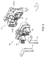
- the connectors 10 are each a connector for power supply and signal supply. As shown in Figs. 1 to 3 , the connectors 10 are attached to the attaching panel 51 of the housing rack 50 and, when the battery unit 70 is inserted into the housing rack 50, the connector 10 is fitted to a battery-side connector 60 attached to the battery unit 70.
- each connector 10 comprises a housing 20 which is fixed on its back side to the attaching panel 51 of the housing rack 50, a pair of power supply contacts 30 which are held by the housing 20, signal housings 40 which are attached to the housing 20 and hold signal contacts 40b, nuts 41 which are attached to the housing 20, a gasket 42 which is attached to the housing 20, and spacer members 43 which are attached to the housing 20, and further comprises, as shown in Fig. 2 , first bolts 44 for fixing the housing 20 to the attaching panel 51 and second bolts 45 for fixing the housing 20, the power supply contacts 30, and the bus bars 54 to the attaching panel 51.
- the housing 20 has an attaching base portion 21 which is fixed to the attaching panel 51 of the housing rack 50, a fitting portion 22 which is disposed more on the front side than the attaching base portion 21, and a signal housing holding portion 25 which is penetratingly formed along the first direction X and holds the signal housings 40.
- the attaching base portion 21 has a portion located outside a receiving frame portion 22a (fitting portion 22) when seen in the first direction X and this portion has first bolt holes 21 a for the first bolts 44 to pass through, second bolt holes 21 b for the second bolts 45 to pass through, and guide portions 21 c for guiding second portions 32 of the power supply contacts 30 when the power supply contacts 30 are attached to and detached from the housing 20.
- the fitting portion 22 has the receiving frame portion 22a and a bottom portion 22b, a receiving space 22c which is defined by the receiving frame portion 22a and the bottom portion 22b and open to the front side of the housing 20 for allowing the battery-side connector 60 to be inserted and received from the front side of the housing 20, spacer holding portions 22d formed on the bottom portion 22b for holding the spacer members 43, a guide portion 22e formed on an inner wall of the receiving frame portion 22a for guiding the battery-side connector 60, and movement restricting portions 22f each for restricting movement of the second portion 32 of the power supply contact 30 in the first direction X jointly with part, facing the movement restricting portion 22f in the first direction X, of the attaching base portion 21.
- the housing 20 further has through-holes 23 formed through the bottom portion 22b of the fitting portion 22 along the first direction X and layout spaces 24 each formed between the attaching base portion 21 and the fitting portion 22, each formed toward the side surface side of the housing 20 from an end portion, on the back side, of the through-hole 23, each communicating with the through-hole 23, and each open to the outside on the side surface side of the housing 20.
- the through-hole 23 and the layout space 24 have sizes, positions, and shapes that can allow the power supply contact 30 to be disposed at a predetermined position in the housing 20 by inserting the power supply contact 30, with its first portion 31 at the head, into the housing 20 through the layout space 24 from the side surface of the housing 20.
- the power supply contacts 30 are electrically connected to battery-side contacts (not illustrated) of the battery-side connector 60 when the connector 10 and the battery-side connector 60 are fitted to each other. As shown in Fig. 4 , the power supply contacts 30 are arranged in a pair parallel to each other in the second direction Y with respect to the housing 20. As shown in Figs. 1 and 7 , the power supply contacts 30 of the connectors 10 attached to the housing rack 50 are connected to each other by the bus bars 54 so that the connectors 10 are connected in series by the bus bars 54. The power supply contacts 30 are disposed in an insulated state from the signal contacts 40b.
- the power supply contacts 30 are formed of a conductive metal (tough pitch copper, copper with a purity of about 99%) and have the same shape. Each power supply contact 30 has a conductivity of 50% or more assuming that the conductivity of pure copper is 100%. Each power supply contact 30 is formed by punching a metal plate into a predetermined shape and then bending a predetermined portion thereof and thus has a shape with no overlapping portion when developed on a plane.
- each power supply contact 30 integrally has the second portion 32 formed in a flat plate shape and the first portion 31 of a flat plate shape standing perpendicular (or substantially perpendicular) to the second portion 32 at the middle, in a longitudinal direction, of the second portion 32.
- the first portion 31 of the power supply contact 30 extends in the first direction X and, in the state where the power supply contact 30 is mounted to the housing 20, the first portion 31 is partially disposed in the through-hole 23 and partially disposed in the receiving space 22c.
- the first portion 31 located in the receiving space 22c serves as a contact portion which is brought into contact with the battery-side contact (not illustrated) of the battery-side connector 60.
- the power supply contact 30 is formed as a pin contact so that the first portion (contact portion) 31 is formed in a pin shape.
- the first portion (contact portion) 31 may be formed in a socket shape.
- the second portion 32 of the power supply contact 30 is partially disposed in the layout space 24 in the state where the power supply contact 30 is mounted to the housing 20.
- the second portion 32 has portions located outside the receiving frame portion 22a (fitting portion 22) and protruding toward both sides in the third direction Z when seen in the first direction X and these portions each have a bolt hole 32a for the second bolt 45 to pass through.
- the bolt holes 32a are respectively formed at both ends, in the third direction Z, of the second portion 32 and, in the state where the power supply contact 30 is mounted to the housing 20, the bolt holes 32a are formed at positions overlapping, in the first direction X, the second bolt holes 21 b formed in the attaching base portion 21.
- the second portion 32 of the power supply contact 30 serves as connecting portions with the bus bars 54.
- the signal housings 40 are inserted from the back side of the housing 20 into the signal housing holding portion 25 formed in the housing 20 and are locked to the housing 20 by mounting spring portions 40a provided to the signal housings 40. As shown in Fig. 4 , the signal housings 40 are partially located in the receiving space 22c of the housing 20.
- Symbol 55 shown in Fig. 2 denotes signal lines (electric wires) connecting the signal contacts 40b of the connectors 10 in series and thus connecting the connectors 10 in series.
- the signal housings 40 are arranged in a pair in each connector 10.
- the signal contacts 40b are arranged in a plurality in each connector 10 (in each signal housing 40). In each connector 10 (in each signal housing 40), the signal contacts 40b are arranged in a lattice shape in a mutually insulated state.
- Each spacer member 43 is formed as a spring pin having a groove on its outer periphery. As shown in Figs. 4 and 5 , each spacer member 43 is detachably mounted to the spacer holding portion 22d of the housing 20 from the front side of the housing 20 and presses the first portion 31 of the power supply contact 30 against an edge portion of the through-hole 23 in the second direction Y, thereby preventing backlash between the through-hole 23 and the first portion 31.
- each first bolt 44 is fitted from the front side of the housing 20 into the first bolt hole 21 a formed in the housing 20 and a bolt hole (not illustrated) formed in the attaching panel 51, thereby fixing the housing 20 to the attaching panel 51.
- each second bolt (connecting member) 45 is fitted from the front side of the housing 20 into the second bolt hole 21 b formed in the housing 20, the bolt hole 32a formed in the second portion 32 of the power supply contact 30, a bolt hole 54a formed in the bus bar 54, and a bolt hole (not illustrated) formed in the attaching panel 51, thereby fixing the housing 20, the power supply contact 30, and the bus bar 54 to the attaching panel 51 and thus connecting the bus bar 54 and the power supply contact 30 together.
- the specific manner of fixing the housing 20, the power supply contact 30, and the bus bar 54 to the attaching panel 51 is not limited to the above.
- the housing 20, the power supply contact 30, and the bus bar 54 may be fixed to the attaching panel 51 by a pin (connecting member) which is press-fitted into the attaching panel 51.
- the second bolt (connecting member) 45 may be fixed using a nut.
- a tapping screw (connecting member), which requires no nut or bolt hole, may be used.
- a spring washer may be interposed if necessary.
- the housing rack 50 has the attaching panel 51 to which the connectors 10 are attached, and the frame 52 defining the battery unit housing portions 53 each for housing the battery unit 70.
- the battery unit 70 is guided by the frame 52 of the housing rack 50 when it is inserted into the housing rack 50, while, the battery unit 70 is supported by the frame 52 of the housing rack 50 when it is housed in the housing rack 50.
- the battery-side connector 60 is attached to a casing 71 of the battery unit 70 and, when the battery unit 70 is inserted into the housing rack 50, the battery-side connector 60 is fitted to the connector 10 attached to the housing rack 50, thereby establishing electrical connection between battery-side bus bars 73 incorporated in the battery unit 70 and connected to batteries (secondary batteries) 72 and the power supply contacts 30. As shown in Fig.
- the battery-side connector 60 comprises a first battery-side housing 61 which is attached to the casing 71 in the state where it is movable at least in the second direction Y, second battery-side housings 62 each attached to the first battery-side housing 61 so as to be movable in the second direction Y relative to the first battery-side housing 61, and power supply battery-side contacts (not illustrated) housed in contact housing portions (not illustrated) each formed by the first battery-side housing 61 and the second battery-side housing 62.
- the power supply contact 30 is damaged due to heat generation or the like caused by flowing a large current and thus should be replaced immediately.
- the power supply contact 30 is replaced by the following steps.
- the spacer member 43 is removed from the housing 20 on the front side of the housing 20 (second step).
- the order of the first and second steps may be reversed to the above.
- the movement of the first portion 31 of the power supply contact 30 is restricted in the second direction Y and the third direction Z by the edge portion of the through-hole 23 while the movement of the second portion 32 of the power supply contact 30 is restricted in the first direction X by the attaching base portion 21 and the movement restricting portion 22f. Consequently, the power supply contact 30 is loosely held by the housing 20 and thus does not come off the housing 20.
- the power supply contact 30 is caused to slide outward in the second direction Y relative to the housing 20 so that the first portion 31 of the power supply contact 30 is pulled out of the through-hole 23 and simultaneously the second portion 32 of the power supply contact 30 is pulled out of the layout space 24, thereby removing the power supply contact 30 from the layout space 24 which is open to the outside at the side surface of the housing 20 (third step).
- a new power supply contact 30 is inserted, with its first portion 31 at the head, into the housing 20 through the layout space 24 so that the power supply contact 30 is disposed at the predetermined position in the housing 20 (fourth step).
- the movement of the first portion 31 of the power supply contact 30 is restricted in the second direction Y and the third direction Z by the edge portion of the through-hole 23 while the movement of the second portion 32 of the power supply contact 30 is restricted in the first direction X by the attaching base portion 21 and the movement restricting portion 22f. Consequently, the power supply contact 30 is loosely held by the housing 20 and thus does not come off the housing 20.
- the spacer member 43 is mounted to the spacer holding portion 22d of the housing 20 (sixth step).
- the order of the fifth and sixth steps may be reversed to the above.
- the battery unit housing portions 53 are arranged in a lattice shape with 3 rows ⁇ 4 columns (second direction Y ⁇ third direction Z) and, following this, the connectors 10 are attached to the attaching panel 51 in a lattice shape with 3 rows ⁇ 4 columns (second direction Y ⁇ third direction Z).
- the specific numbers of rows and columns are not limited to the above.
- the connectors 10 are connected in series by the bus bars 54.
- the right-side (or left-side) power supply contacts 30 of the connectors 10 located above and the left-side (or right-side) power supply contacts 30 of the connectors 10 located below are obliquely connected to each other by the bus bar 54 to thereby connect together the connectors 10 aligned in the third direction Z and further the connectors 10 adjacent to each other in the second direction Y are connected together by the bus bar 54 disposed along the second direction Y.
- the dimension M in the third direction Z of each battery unit housing portion 53 and the dimension L in the second direction Y of each battery unit housing portion 53 are determined according to the dimensions in the second direction Y and the third direction Z of the battery unit 70. Therefore, as shown in Fig. 8 of the comparative example, when each power supply contact 30 is provided with a single bolt hole 32a, it is difficult to adjust the dimensional relationship between the bus bar 54 (54A) for connection between the connectors 10 in the third direction Z and the bus bar 54 (54B) for connection between the connectors 10 in the second direction Y so that the bus bars with two kinds of dimensions are required.
- each power supply contact 30 is provided with the two bolt holes 32a and these two bolt holes 32a are aligned in the third direction Z, thereby adjusting the required dimension of the bus bar 54 (54A) for connection between the connectors 10 in the third direction Z so that the dimension of the bus bar 54 (54A) for connection between the connectors 10 in the third direction Z and the dimension of the bus bar 54 (54B) for connection between the connectors 10 in the second direction Y are set to be equal to each other.
- a specific manner of the conductive member may be any as long as it can connect between the connectors 10.
- a feeder 54' shown in Fig. 9 may be used instead of each of part or all of the bus bars 54.
- Terminals 54a' each having a hole 54b' for the second bolt 45 to pass through are connected to both ends of the feeder 54'.
- the connectors 10 are connected in series by the conductive members (bus bars 54). However, as shown in Fig. 10 , the connectors 10 may be connected in parallel by conductive members (bus bars 54). Further, the connectors 10 may be connected in series and parallel combination by conductive members (bus bars 54).
- the housing rack 50 for housing the battery units 70 is provided in advance with the connectors 10 and the conductive members (bus bars 54) connecting between the connectors 10, the battery units 70 can be connected to each other by the connectors 10 and the conductive members (bus bars 54) in the state where the battery units 70 are inserted into the housing rack 50 and, only by the extraction and insertion operations of each battery unit 70 with respect to the housing rack 50, it is possible to remove and attach the battery unit 70 from and to the electrical storage device 1. Therefore, the workload and work risk can be reduced so that each battery unit 70 can be simply and safely removed from and attached to the electrical storage device 1.
- the connector 10 is attached to the attaching panel 51 from the battery unit housing portion 53 side using the first and second bolts 44 and 45 which are fitted through the connector 10 from the battery unit housing portion 53 side, it is possible to easily attach and detach the connector 10 on the battery unit housing portion 53 side where a workspace is easy to ensure.
- the conductive member (bus bar 54) is attached to the connector 10 and the attaching panel 51 from the battery unit housing portion 53 side using the second bolt 45 which is fitted through the conductive member (bus bar 54) from the battery unit housing portion 53 side, it is possible to easily attach and detach the conductive member (bus bar 54) on the battery unit housing portion 53 side where a workspace is easy to ensure.
- the connector 10 is configured such that the power supply contact 30 can be inserted and removed from the side surface side of the housing 20, the insertion/removal operation of the power supply contact 30 can be carried out on the front side, where the fitting portion 22 to the battery-side connector 60 is disposed, of the housing 20. Therefore, a workspace is easy to ensure so that the replacement operation of the power supply contact 30 can be easily achieved in the state where the connector 10 is attached to the attaching panel 51, and further, it is not necessary to ensure a workspace on the back side of the attaching panel 51 so that space saving of the device can be realized.
Landscapes
- Chemical & Material Sciences (AREA)
- Chemical Kinetics & Catalysis (AREA)
- Electrochemistry (AREA)
- General Chemical & Material Sciences (AREA)
- Connection Of Batteries Or Terminals (AREA)
- Battery Mounting, Suspending (AREA)
- Connector Housings Or Holding Contact Members (AREA)
- Charge And Discharge Circuits For Batteries Or The Like (AREA)
- Details Of Connecting Devices For Male And Female Coupling (AREA)
Applications Claiming Priority (2)
| Application Number | Priority Date | Filing Date | Title |
|---|---|---|---|
| JP2011203126A JP5145452B1 (ja) | 2011-09-16 | 2011-09-16 | 蓄電装置 |
| PCT/JP2012/072410 WO2013038941A1 (ja) | 2011-09-16 | 2012-09-04 | 蓄電装置 |
Publications (3)
| Publication Number | Publication Date |
|---|---|
| EP2741344A1 true EP2741344A1 (de) | 2014-06-11 |
| EP2741344A4 EP2741344A4 (de) | 2015-02-25 |
| EP2741344B1 EP2741344B1 (de) | 2016-05-18 |
Family
ID=47883172
Family Applications (1)
| Application Number | Title | Priority Date | Filing Date |
|---|---|---|---|
| EP12831435.8A Active EP2741344B1 (de) | 2011-09-16 | 2012-09-04 | Elektrische speichervorrichtung |
Country Status (7)
| Country | Link |
|---|---|
| US (1) | US9537123B2 (de) |
| EP (1) | EP2741344B1 (de) |
| JP (1) | JP5145452B1 (de) |
| KR (2) | KR20140050692A (de) |
| CN (1) | CN103748704B (de) |
| TW (1) | TWI485946B (de) |
| WO (1) | WO2013038941A1 (de) |
Cited By (2)
| Publication number | Priority date | Publication date | Assignee | Title |
|---|---|---|---|---|
| EP3595041A4 (de) * | 2017-09-29 | 2020-06-24 | LG Chem, Ltd. | Batteriemodul |
| EP3780152A4 (de) * | 2018-08-15 | 2021-05-26 | Contemporary Amperex Technology Co., Limited | Verbinder und batterieprodukt |
Families Citing this family (13)
| Publication number | Priority date | Publication date | Assignee | Title |
|---|---|---|---|---|
| WO2014155410A1 (ja) * | 2013-03-25 | 2014-10-02 | 三洋電機株式会社 | 蓄電池システム |
| JP6052427B2 (ja) * | 2013-11-22 | 2016-12-27 | 株式会社オートネットワーク技術研究所 | 蓄電素子群の接続構造 |
| JP6425093B2 (ja) * | 2015-03-03 | 2018-11-21 | 株式会社オートネットワーク技術研究所 | 蓄電パック |
| JP6434468B2 (ja) * | 2016-09-30 | 2018-12-05 | 株式会社オートネットワーク技術研究所 | 接続モジュール |
| JP6469062B2 (ja) * | 2016-09-30 | 2019-02-13 | 株式会社オートネットワーク技術研究所 | 接続モジュール |
| US11705593B2 (en) * | 2016-12-26 | 2023-07-18 | Panasonic Intellectual Property Management Co., Ltd. | Rack type power source device |
| US10916759B2 (en) * | 2017-01-11 | 2021-02-09 | Sanyo Electric Co., Ltd. | Power storage system |
| JP6928826B2 (ja) * | 2017-04-12 | 2021-09-01 | パナソニックIpマネジメント株式会社 | 電池モジュールおよび蓄電ユニット |
| JP6798405B2 (ja) * | 2017-04-18 | 2020-12-09 | 株式会社オートネットワーク技術研究所 | 蓄電モジュールユニットおよび蓄電パック |
| WO2019130880A1 (ja) * | 2017-12-28 | 2019-07-04 | Necエナジーデバイス株式会社 | 電池システム及び保持体 |
| CN208570740U (zh) * | 2018-08-27 | 2019-03-01 | 阳光电源股份有限公司 | 一种高度集成的移动式储能系统 |
| DE102018220184B4 (de) * | 2018-11-23 | 2022-05-25 | Volkswagen Aktiengesellschaft | Steckervorrichtung für eine Batterie, Batterie und Kraftfahrzeug |
| CN114552101A (zh) * | 2022-03-25 | 2022-05-27 | 中创新航科技股份有限公司 | 插箱放置架、储能机架及电池簇 |
Citations (5)
| Publication number | Priority date | Publication date | Assignee | Title |
|---|---|---|---|---|
| EP0892450A2 (de) * | 1997-03-24 | 1999-01-20 | Matsushita Electric Industrial Co., Ltd. | Stromversorgungseinheitsbatterie |
| EP0964470A1 (de) * | 1997-10-06 | 1999-12-15 | Matsushita Electric Industrial Co., Ltd. | Batteriestromversorgung |
| US20100247994A1 (en) * | 2009-03-26 | 2010-09-30 | Jun Young Park | Battery holder for a battery array, and battery array |
| US20100320969A1 (en) * | 2009-04-09 | 2010-12-23 | Makita Corporation | Battery pack |
| EP2333872A1 (de) * | 2009-11-24 | 2011-06-15 | Samsung SDI Co., Ltd. | Batteriepack mit hoher Kapazität |
Family Cites Families (15)
| Publication number | Priority date | Publication date | Assignee | Title |
|---|---|---|---|---|
| JPS5949377A (ja) | 1982-09-13 | 1984-03-21 | Yuukoushiya:Kk | 浮力式動力発生装置 |
| JPS5949377U (ja) * | 1982-09-25 | 1984-04-02 | 松下電工株式会社 | ア−ス付コンセント |
| JP3516649B2 (ja) * | 2000-10-04 | 2004-04-05 | 日本電信電話株式会社 | 蓄電池収納キャビネット及び蓄電池収納接続方法 |
| JP2003257516A (ja) | 2002-03-06 | 2003-09-12 | Tdk Corp | ブスバー及びそれを用いた電源装置 |
| JP3881317B2 (ja) | 2003-01-30 | 2007-02-14 | 川崎重工業株式会社 | 鉄道車両用バッテリー箱 |
| TWI243500B (en) * | 2004-07-08 | 2005-11-11 | Antig Tech Co Ltd | Rechargeable battery device with a connection interface |
| JP5070681B2 (ja) * | 2005-04-07 | 2012-11-14 | 日産自動車株式会社 | 組電池 |
| JP5220588B2 (ja) * | 2005-05-02 | 2013-06-26 | エルジー・ケム・リミテッド | 安全性が向上した中型又は大型の改良バッテリーパック |
| KR100881640B1 (ko) * | 2005-06-15 | 2009-02-04 | 주식회사 엘지화학 | 중대형 전지팩용 전지모듈 |
| JP4956773B2 (ja) | 2005-07-05 | 2012-06-20 | 日産自動車株式会社 | 電池パックおよび電池パック用ケース |
| JP5072421B2 (ja) * | 2007-04-25 | 2012-11-14 | スリオジャパン株式会社 | 電気コネクタ |
| JP4949311B2 (ja) * | 2008-04-10 | 2012-06-06 | 矢崎総業株式会社 | コネクタ |
| JP2010244760A (ja) * | 2009-04-02 | 2010-10-28 | Mitsubishi Heavy Ind Ltd | 二次電池集合体 |
| KR101255243B1 (ko) * | 2011-04-15 | 2013-04-16 | 삼성에스디아이 주식회사 | 랙 하우징 조립체 및 이를 구비한 전력저장장치 |
| JP5112544B1 (ja) * | 2011-07-19 | 2013-01-09 | 日本航空電子工業株式会社 | コネクタおよび収容ラック |
-
2011
- 2011-09-16 JP JP2011203126A patent/JP5145452B1/ja active Active
-
2012
- 2012-09-04 EP EP12831435.8A patent/EP2741344B1/de active Active
- 2012-09-04 TW TW101132096A patent/TWI485946B/zh active
- 2012-09-04 WO PCT/JP2012/072410 patent/WO2013038941A1/ja active Application Filing
- 2012-09-04 KR KR1020147004881A patent/KR20140050692A/ko active Application Filing
- 2012-09-04 CN CN201280041165.2A patent/CN103748704B/zh active Active
- 2012-09-04 KR KR1020167029998A patent/KR101834689B1/ko active IP Right Grant
- 2012-09-04 US US14/240,040 patent/US9537123B2/en active Active
Patent Citations (5)
| Publication number | Priority date | Publication date | Assignee | Title |
|---|---|---|---|---|
| EP0892450A2 (de) * | 1997-03-24 | 1999-01-20 | Matsushita Electric Industrial Co., Ltd. | Stromversorgungseinheitsbatterie |
| EP0964470A1 (de) * | 1997-10-06 | 1999-12-15 | Matsushita Electric Industrial Co., Ltd. | Batteriestromversorgung |
| US20100247994A1 (en) * | 2009-03-26 | 2010-09-30 | Jun Young Park | Battery holder for a battery array, and battery array |
| US20100320969A1 (en) * | 2009-04-09 | 2010-12-23 | Makita Corporation | Battery pack |
| EP2333872A1 (de) * | 2009-11-24 | 2011-06-15 | Samsung SDI Co., Ltd. | Batteriepack mit hoher Kapazität |
Non-Patent Citations (1)
| Title |
|---|
| See also references of WO2013038941A1 * |
Cited By (3)
| Publication number | Priority date | Publication date | Assignee | Title |
|---|---|---|---|---|
| EP3595041A4 (de) * | 2017-09-29 | 2020-06-24 | LG Chem, Ltd. | Batteriemodul |
| US11031659B2 (en) | 2017-09-29 | 2021-06-08 | Lg Chem, Ltd. | Battery module |
| EP3780152A4 (de) * | 2018-08-15 | 2021-05-26 | Contemporary Amperex Technology Co., Limited | Verbinder und batterieprodukt |
Also Published As
| Publication number | Publication date |
|---|---|
| KR20160128450A (ko) | 2016-11-07 |
| JP5145452B1 (ja) | 2013-02-20 |
| CN103748704B (zh) | 2016-11-02 |
| KR101834689B1 (ko) | 2018-03-05 |
| TWI485946B (zh) | 2015-05-21 |
| EP2741344B1 (de) | 2016-05-18 |
| US20140186676A1 (en) | 2014-07-03 |
| CN103748704A (zh) | 2014-04-23 |
| WO2013038941A1 (ja) | 2013-03-21 |
| KR20140050692A (ko) | 2014-04-29 |
| TW201318291A (zh) | 2013-05-01 |
| EP2741344A4 (de) | 2015-02-25 |
| US9537123B2 (en) | 2017-01-03 |
| JP2013065445A (ja) | 2013-04-11 |
Similar Documents
| Publication | Publication Date | Title |
|---|---|---|
| EP2741344B1 (de) | Elektrische speichervorrichtung | |
| US9124041B2 (en) | Connector and housing structure | |
| EP2775548B1 (de) | Energiespeichervorrichtung | |
| KR100910100B1 (ko) | 전기기기의 단자 장치 | |
| EP2784841B1 (de) | Verbinder für eine batterieeinheit und batterieeinheit damit | |
| JP5119632B2 (ja) | 組電池および組電池の製造方法 | |
| EP2693573B1 (de) | Elektrisches Leistungskreisverbindungssystem und Verfahren | |
| CN105474469A (zh) | 用于特别是外部路由总线系统的承插结构的接触元件 | |
| EP2544261A1 (de) | Batterieverbindungsanordnung | |
| US20150357620A1 (en) | Battery wiring module | |
| EP2485332A1 (de) | Befestigungsstruktur für einen substratstecker | |
| JP2013120695A (ja) | 電池モジュール接続装置 | |
| CN109716554B (zh) | 外部连接母线保持模块以及连接模块 | |
| EP2581964A1 (de) | Batteriepack | |
| JP2015122143A (ja) | バスバーの取付構造 | |
| JP5532073B2 (ja) | 組電池および組電池の製造方法 | |
| CN220306615U (zh) | 一种便捷检修的pdu排插结构 | |
| CN217721800U (zh) | 服务器机柜和服务器系统 | |
| CN112713430A (zh) | 电源供应装置及其端子座 | |
| CN101847911A (zh) | 马达驱动器及其电源接线装置 |
Legal Events
| Date | Code | Title | Description |
|---|---|---|---|
| PUAI | Public reference made under article 153(3) epc to a published international application that has entered the european phase |
Free format text: ORIGINAL CODE: 0009012 |
|
| 17P | Request for examination filed |
Effective date: 20140303 |
|
| AK | Designated contracting states |
Kind code of ref document: A1 Designated state(s): AL AT BE BG CH CY CZ DE DK EE ES FI FR GB GR HR HU IE IS IT LI LT LU LV MC MK MT NL NO PL PT RO RS SE SI SK SM TR |
|
| DAX | Request for extension of the european patent (deleted) | ||
| A4 | Supplementary search report drawn up and despatched |
Effective date: 20150126 |
|
| RIC1 | Information provided on ipc code assigned before grant |
Ipc: H01M 2/10 20060101AFI20150120BHEP Ipc: H01R 13/74 20060101ALI20150120BHEP |
|
| 17Q | First examination report despatched |
Effective date: 20150910 |
|
| GRAP | Despatch of communication of intention to grant a patent |
Free format text: ORIGINAL CODE: EPIDOSNIGR1 |
|
| INTG | Intention to grant announced |
Effective date: 20151125 |
|
| GRAS | Grant fee paid |
Free format text: ORIGINAL CODE: EPIDOSNIGR3 |
|
| GRAA | (expected) grant |
Free format text: ORIGINAL CODE: 0009210 |
|
| AK | Designated contracting states |
Kind code of ref document: B1 Designated state(s): AL AT BE BG CH CY CZ DE DK EE ES FI FR GB GR HR HU IE IS IT LI LT LU LV MC MK MT NL NO PL PT RO RS SE SI SK SM TR |
|
| REG | Reference to a national code |
Ref country code: GB Ref legal event code: FG4D |
|
| REG | Reference to a national code |
Ref country code: CH Ref legal event code: EP |
|
| REG | Reference to a national code |
Ref country code: IE Ref legal event code: FG4D Ref country code: AT Ref legal event code: REF Ref document number: 801142 Country of ref document: AT Kind code of ref document: T Effective date: 20160615 |
|
| REG | Reference to a national code |
Ref country code: DE Ref legal event code: R096 Ref document number: 602012018796 Country of ref document: DE |
|
| REG | Reference to a national code |
Ref country code: NL Ref legal event code: MP Effective date: 20160518 |
|
| REG | Reference to a national code |
Ref country code: LT Ref legal event code: MG4D |
|
| PG25 | Lapsed in a contracting state [announced via postgrant information from national office to epo] |
Ref country code: NO Free format text: LAPSE BECAUSE OF FAILURE TO SUBMIT A TRANSLATION OF THE DESCRIPTION OR TO PAY THE FEE WITHIN THE PRESCRIBED TIME-LIMIT Effective date: 20160818 Ref country code: NL Free format text: LAPSE BECAUSE OF FAILURE TO SUBMIT A TRANSLATION OF THE DESCRIPTION OR TO PAY THE FEE WITHIN THE PRESCRIBED TIME-LIMIT Effective date: 20160518 Ref country code: FI Free format text: LAPSE BECAUSE OF FAILURE TO SUBMIT A TRANSLATION OF THE DESCRIPTION OR TO PAY THE FEE WITHIN THE PRESCRIBED TIME-LIMIT Effective date: 20160518 Ref country code: LT Free format text: LAPSE BECAUSE OF FAILURE TO SUBMIT A TRANSLATION OF THE DESCRIPTION OR TO PAY THE FEE WITHIN THE PRESCRIBED TIME-LIMIT Effective date: 20160518 |
|
| REG | Reference to a national code |
Ref country code: AT Ref legal event code: MK05 Ref document number: 801142 Country of ref document: AT Kind code of ref document: T Effective date: 20160518 |
|
| PG25 | Lapsed in a contracting state [announced via postgrant information from national office to epo] |
Ref country code: PT Free format text: LAPSE BECAUSE OF FAILURE TO SUBMIT A TRANSLATION OF THE DESCRIPTION OR TO PAY THE FEE WITHIN THE PRESCRIBED TIME-LIMIT Effective date: 20160919 Ref country code: SE Free format text: LAPSE BECAUSE OF FAILURE TO SUBMIT A TRANSLATION OF THE DESCRIPTION OR TO PAY THE FEE WITHIN THE PRESCRIBED TIME-LIMIT Effective date: 20160518 Ref country code: GR Free format text: LAPSE BECAUSE OF FAILURE TO SUBMIT A TRANSLATION OF THE DESCRIPTION OR TO PAY THE FEE WITHIN THE PRESCRIBED TIME-LIMIT Effective date: 20160819 Ref country code: RS Free format text: LAPSE BECAUSE OF FAILURE TO SUBMIT A TRANSLATION OF THE DESCRIPTION OR TO PAY THE FEE WITHIN THE PRESCRIBED TIME-LIMIT Effective date: 20160518 Ref country code: HR Free format text: LAPSE BECAUSE OF FAILURE TO SUBMIT A TRANSLATION OF THE DESCRIPTION OR TO PAY THE FEE WITHIN THE PRESCRIBED TIME-LIMIT Effective date: 20160518 Ref country code: ES Free format text: LAPSE BECAUSE OF FAILURE TO SUBMIT A TRANSLATION OF THE DESCRIPTION OR TO PAY THE FEE WITHIN THE PRESCRIBED TIME-LIMIT Effective date: 20160518 Ref country code: LV Free format text: LAPSE BECAUSE OF FAILURE TO SUBMIT A TRANSLATION OF THE DESCRIPTION OR TO PAY THE FEE WITHIN THE PRESCRIBED TIME-LIMIT Effective date: 20160518 |
|
| PG25 | Lapsed in a contracting state [announced via postgrant information from national office to epo] |
Ref country code: IT Free format text: LAPSE BECAUSE OF FAILURE TO SUBMIT A TRANSLATION OF THE DESCRIPTION OR TO PAY THE FEE WITHIN THE PRESCRIBED TIME-LIMIT Effective date: 20160518 |
|
| PG25 | Lapsed in a contracting state [announced via postgrant information from national office to epo] |
Ref country code: DK Free format text: LAPSE BECAUSE OF FAILURE TO SUBMIT A TRANSLATION OF THE DESCRIPTION OR TO PAY THE FEE WITHIN THE PRESCRIBED TIME-LIMIT Effective date: 20160518 Ref country code: EE Free format text: LAPSE BECAUSE OF FAILURE TO SUBMIT A TRANSLATION OF THE DESCRIPTION OR TO PAY THE FEE WITHIN THE PRESCRIBED TIME-LIMIT Effective date: 20160518 Ref country code: CZ Free format text: LAPSE BECAUSE OF FAILURE TO SUBMIT A TRANSLATION OF THE DESCRIPTION OR TO PAY THE FEE WITHIN THE PRESCRIBED TIME-LIMIT Effective date: 20160518 Ref country code: RO Free format text: LAPSE BECAUSE OF FAILURE TO SUBMIT A TRANSLATION OF THE DESCRIPTION OR TO PAY THE FEE WITHIN THE PRESCRIBED TIME-LIMIT Effective date: 20160518 Ref country code: SK Free format text: LAPSE BECAUSE OF FAILURE TO SUBMIT A TRANSLATION OF THE DESCRIPTION OR TO PAY THE FEE WITHIN THE PRESCRIBED TIME-LIMIT Effective date: 20160518 |
|
| REG | Reference to a national code |
Ref country code: DE Ref legal event code: R097 Ref document number: 602012018796 Country of ref document: DE |
|
| PG25 | Lapsed in a contracting state [announced via postgrant information from national office to epo] |
Ref country code: SM Free format text: LAPSE BECAUSE OF FAILURE TO SUBMIT A TRANSLATION OF THE DESCRIPTION OR TO PAY THE FEE WITHIN THE PRESCRIBED TIME-LIMIT Effective date: 20160518 Ref country code: AT Free format text: LAPSE BECAUSE OF FAILURE TO SUBMIT A TRANSLATION OF THE DESCRIPTION OR TO PAY THE FEE WITHIN THE PRESCRIBED TIME-LIMIT Effective date: 20160518 Ref country code: BE Free format text: LAPSE BECAUSE OF NON-PAYMENT OF DUE FEES Effective date: 20160518 Ref country code: PL Free format text: LAPSE BECAUSE OF FAILURE TO SUBMIT A TRANSLATION OF THE DESCRIPTION OR TO PAY THE FEE WITHIN THE PRESCRIBED TIME-LIMIT Effective date: 20160518 |
|
| PLBE | No opposition filed within time limit |
Free format text: ORIGINAL CODE: 0009261 |
|
| STAA | Information on the status of an ep patent application or granted ep patent |
Free format text: STATUS: NO OPPOSITION FILED WITHIN TIME LIMIT |
|
| 26N | No opposition filed |
Effective date: 20170221 |
|
| PG25 | Lapsed in a contracting state [announced via postgrant information from national office to epo] |
Ref country code: MC Free format text: LAPSE BECAUSE OF FAILURE TO SUBMIT A TRANSLATION OF THE DESCRIPTION OR TO PAY THE FEE WITHIN THE PRESCRIBED TIME-LIMIT Effective date: 20160518 |
|
| REG | Reference to a national code |
Ref country code: CH Ref legal event code: PL |
|
| GBPC | Gb: european patent ceased through non-payment of renewal fee |
Effective date: 20160904 |
|
| PG25 | Lapsed in a contracting state [announced via postgrant information from national office to epo] |
Ref country code: SI Free format text: LAPSE BECAUSE OF FAILURE TO SUBMIT A TRANSLATION OF THE DESCRIPTION OR TO PAY THE FEE WITHIN THE PRESCRIBED TIME-LIMIT Effective date: 20160518 |
|
| REG | Reference to a national code |
Ref country code: IE Ref legal event code: MM4A |
|
| REG | Reference to a national code |
Ref country code: FR Ref legal event code: ST Effective date: 20170531 |
|
| PG25 | Lapsed in a contracting state [announced via postgrant information from national office to epo] |
Ref country code: FR Free format text: LAPSE BECAUSE OF NON-PAYMENT OF DUE FEES Effective date: 20160930 Ref country code: IE Free format text: LAPSE BECAUSE OF NON-PAYMENT OF DUE FEES Effective date: 20160904 Ref country code: CH Free format text: LAPSE BECAUSE OF NON-PAYMENT OF DUE FEES Effective date: 20160930 Ref country code: GB Free format text: LAPSE BECAUSE OF NON-PAYMENT OF DUE FEES Effective date: 20160904 Ref country code: LI Free format text: LAPSE BECAUSE OF NON-PAYMENT OF DUE FEES Effective date: 20160930 |
|
| PG25 | Lapsed in a contracting state [announced via postgrant information from national office to epo] |
Ref country code: LU Free format text: LAPSE BECAUSE OF NON-PAYMENT OF DUE FEES Effective date: 20160904 |
|
| PG25 | Lapsed in a contracting state [announced via postgrant information from national office to epo] |
Ref country code: CY Free format text: LAPSE BECAUSE OF FAILURE TO SUBMIT A TRANSLATION OF THE DESCRIPTION OR TO PAY THE FEE WITHIN THE PRESCRIBED TIME-LIMIT Effective date: 20160518 Ref country code: HU Free format text: LAPSE BECAUSE OF FAILURE TO SUBMIT A TRANSLATION OF THE DESCRIPTION OR TO PAY THE FEE WITHIN THE PRESCRIBED TIME-LIMIT; INVALID AB INITIO Effective date: 20120904 |
|
| PG25 | Lapsed in a contracting state [announced via postgrant information from national office to epo] |
Ref country code: MT Free format text: LAPSE BECAUSE OF NON-PAYMENT OF DUE FEES Effective date: 20160930 Ref country code: MK Free format text: LAPSE BECAUSE OF FAILURE TO SUBMIT A TRANSLATION OF THE DESCRIPTION OR TO PAY THE FEE WITHIN THE PRESCRIBED TIME-LIMIT Effective date: 20160518 Ref country code: IS Free format text: LAPSE BECAUSE OF FAILURE TO SUBMIT A TRANSLATION OF THE DESCRIPTION OR TO PAY THE FEE WITHIN THE PRESCRIBED TIME-LIMIT Effective date: 20160518 |
|
| PG25 | Lapsed in a contracting state [announced via postgrant information from national office to epo] |
Ref country code: BG Free format text: LAPSE BECAUSE OF FAILURE TO SUBMIT A TRANSLATION OF THE DESCRIPTION OR TO PAY THE FEE WITHIN THE PRESCRIBED TIME-LIMIT Effective date: 20160518 |
|
| PG25 | Lapsed in a contracting state [announced via postgrant information from national office to epo] |
Ref country code: AL Free format text: LAPSE BECAUSE OF FAILURE TO SUBMIT A TRANSLATION OF THE DESCRIPTION OR TO PAY THE FEE WITHIN THE PRESCRIBED TIME-LIMIT Effective date: 20160518 Ref country code: TR Free format text: LAPSE BECAUSE OF FAILURE TO SUBMIT A TRANSLATION OF THE DESCRIPTION OR TO PAY THE FEE WITHIN THE PRESCRIBED TIME-LIMIT Effective date: 20160518 |
|
| REG | Reference to a national code |
Ref country code: DE Ref legal event code: R079 Ref document number: 602012018796 Country of ref document: DE Free format text: PREVIOUS MAIN CLASS: H01M0002100000 Ipc: H01M0050200000 |
|
| PGFP | Annual fee paid to national office [announced via postgrant information from national office to epo] |
Ref country code: DE Payment date: 20230802 Year of fee payment: 12 |