EP0878570B1 - Procédé pour former un tissu avec des lisières et au moins une lisière de retenue sur métiers à tisser ainsi que dispositif pour la mise en oeuvre de ce procédé - Google Patents
Procédé pour former un tissu avec des lisières et au moins une lisière de retenue sur métiers à tisser ainsi que dispositif pour la mise en oeuvre de ce procédé Download PDFInfo
- Publication number
- EP0878570B1 EP0878570B1 EP98107341A EP98107341A EP0878570B1 EP 0878570 B1 EP0878570 B1 EP 0878570B1 EP 98107341 A EP98107341 A EP 98107341A EP 98107341 A EP98107341 A EP 98107341A EP 0878570 B1 EP0878570 B1 EP 0878570B1
- Authority
- EP
- European Patent Office
- Prior art keywords
- selvedge
- threads
- catch
- fabric
- leno
- Prior art date
- Legal status (The legal status is an assumption and is not a legal conclusion. Google has not performed a legal analysis and makes no representation as to the accuracy of the status listed.)
- Revoked
Links
- 239000004744 fabric Substances 0.000 title claims abstract description 84
- 238000000034 method Methods 0.000 title claims description 16
- 238000004519 manufacturing process Methods 0.000 claims description 8
- 238000010276 construction Methods 0.000 claims description 6
- 238000005520 cutting process Methods 0.000 claims description 4
- 230000007246 mechanism Effects 0.000 claims 9
- 238000004795 WEFT sequence Methods 0.000 claims 2
- 238000009941 weaving Methods 0.000 abstract description 13
- 241001589086 Bellapiscis medius Species 0.000 description 18
- 239000000463 material Substances 0.000 description 9
- 238000003780 insertion Methods 0.000 description 5
- 230000037431 insertion Effects 0.000 description 5
- 235000014676 Phragmites communis Nutrition 0.000 description 4
- 230000008901 benefit Effects 0.000 description 4
- 230000015572 biosynthetic process Effects 0.000 description 4
- 239000002699 waste material Substances 0.000 description 3
- 230000009471 action Effects 0.000 description 2
- 238000005516 engineering process Methods 0.000 description 2
- 230000008439 repair process Effects 0.000 description 2
- 238000000926 separation method Methods 0.000 description 2
- 229920002994 synthetic fiber Polymers 0.000 description 2
- 230000000454 anti-cipatory effect Effects 0.000 description 1
- 230000008859 change Effects 0.000 description 1
- 230000002950 deficient Effects 0.000 description 1
- 230000001419 dependent effect Effects 0.000 description 1
- 230000006866 deterioration Effects 0.000 description 1
- 230000006872 improvement Effects 0.000 description 1
- 230000014759 maintenance of location Effects 0.000 description 1
- 230000003287 optical effect Effects 0.000 description 1
- 210000000056 organ Anatomy 0.000 description 1
- 230000035515 penetration Effects 0.000 description 1
- 230000000737 periodic effect Effects 0.000 description 1
- 230000002093 peripheral effect Effects 0.000 description 1
- 230000008569 process Effects 0.000 description 1
- 230000007480 spreading Effects 0.000 description 1
- 238000003892 spreading Methods 0.000 description 1
- 230000001360 synchronised effect Effects 0.000 description 1
- 230000007704 transition Effects 0.000 description 1
- 230000000007 visual effect Effects 0.000 description 1
- 210000002268 wool Anatomy 0.000 description 1
- 238000010626 work up procedure Methods 0.000 description 1
Images


Classifications
-
- D—TEXTILES; PAPER
- D03—WEAVING
- D03C—SHEDDING MECHANISMS; PATTERN CARDS OR CHAINS; PUNCHING OF CARDS; DESIGNING PATTERNS
- D03C7/00—Leno or similar shedding mechanisms
- D03C7/04—Mechanisms having discs oscillating about a weftwise axis and having apertures for warp threads
-
- D—TEXTILES; PAPER
- D03—WEAVING
- D03D—WOVEN FABRICS; METHODS OF WEAVING; LOOMS
- D03D47/00—Looms in which bulk supply of weft does not pass through shed, e.g. shuttleless looms, gripper shuttle looms, dummy shuttle looms
- D03D47/40—Forming selvedges
Definitions
- the invention relates to methods for producing a fabric with fabric strips and at least one temporarily existing catch strip on weaving machines according to the preambles of claims 1 and 2. Such methods are known from GB-A-669 196.
- a rotary edge cutter is provided for producing the fabric strips, which permanently remain on the fabric, and the catch strip, which is intended only to prevent the weft yarn from springing back into the shed and is separated after the weaving process has been completed .
- the two rotary edge rotators have disc-shaped rotating bodies which are arranged coaxially next to each other at the edges of the resulting fabric web in the region of the shed. The axis of rotation of the rotating body is perpendicular to the direction of the warp threads.
- the rotary bodies have in their peripheral area thread guide eyelets, through which the leno threads are passed to form the fabric strips or the Fangleisten threads to form the trap bar. It is expressly pointed out in GB-A-669 196 that the two rotary bodies can be operated either with controlled direction of rotation reversal or without reverse rotation. In the first case, the coils, from which the leno and Fangleisten threads are removed, may be arranged stationary; in the second case, it is necessary to store the coils on a rotary holder. In the preambles of claims 1 and 2 of the present application these two cases are taken into account.
- GB-A-669 196 contains no information about how the drive of the two bodies of revolution should be realized constructively. After the age of this document, however, it can be assumed that the drive is derived mechanically from the main drive of the loom. This must necessarily mean that the two rotary edgebanders operate at a common speed, which is set once in the design of the loom, and that also the phases of the periodic change from forward to reverse rotation can be subsequently changed only with great effort. Furthermore, the possible speed of the conventionally driven rotary edger is not very high, so that they are limited in modern, high-speed running weaving machines.
- rotary edge knives are already known, which are driven independently of the main drive of the loom by its own electric motor. Such a rotary edge cutter can be individually controlled and programmed. This applies, for example, to certain phases of forward and reverse rotation or to the selective setting of single bonds and bond misfires.
- the rotary edge twisters according to DE-A-44 05 776 and DE-A-44 05 777 have been proposed for forming the fabric strips or fabric edges on high-speed modern weaving machines and have proven themselves.
- a further disadvantage is that in the multi-filament crosswheels the Fangleisten threads are mechanically stressed very high, especially by deflections of the threads. It is therefore necessary to use safety catch threads of a tear-resistant material, for example of a synthetic material.
- the Fangmann then consists of natural weft yarn, while the applied as Vollcarderitati Fangleisten threads made of a synthetic yarn.
- a further disadvantage is that in the case of an automatic weft breakage repair, which requires reopening (reverse weaving) of the previously closed shed, the catch wedge compartment setting the defective weft thread is not always released. Then, the weft breakage repair can not be performed in the required short time.
- the invention is therefore based on the object to improve the aforementioned method with and without reversing the rotational body so that the high weaving speeds of modern weaving machines are achieved, at the same time the material used for the catch strips is reduced, the weft threads on both sides of the fabric reliable be held and yet after the separation of the catch strips a high quality, durable fabric strip of beautiful visual effect comes about.
- catch strips no longer have to be as wide as when using the conventional edge twister or in canvas binding catch strips, also required for the catch strips end portions of the weft threads are shorter and also achieved a material savings in the weft threads.
- GNeillrvebmaschinen it was possible to save by the new construction about 25mm weft material per shot.
- the lower mechanical stress of the Fangleisten threads by the present invention used according to the rotary edgers also leads to the fact that the Fangleisten threads in very many cases may consist of the same material as the weft threads, resulting in not only less, but also sorted waste.
- wool tethers may also be used, while in the manufacture of synthetic fabric, synthetic tuck yarns are used. Since the waste is sorted, all separated catch strips can be fed virtually a workup and reuse, which means a cost savings for the weaving.
- the base fabric and the fabric strip consist of the much finer warp threads and leno threads; Therefore, the shed and the fabric strip tray should be kept open as long as possible so that warp threads and leno threads are not disoriented or even damaged by the penetration of the weft thread, for example by touching the gripper.
- the flow .DELTA..alpha Of the rotation body leading the catch strip threads to the rotation body guiding the leno threads allows to fulfill the two opposing requirements, the fabric strip visible after the separation of the catch strips is not only of high quality but also of good optical effect. At the same time prevents the flow ⁇ in the edge formation, the "preliminary work" of the trap bar against the binding point of the shed, as given by the former shorts a better leno thread training.
- the invention also relates to the apparatus required for carrying out the method, which are specified in claims 3 and 4.
- the relevant and taken into account in the preambles of claims 3 and 4 prior art is again the GB-A-669 196th
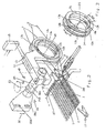
- the device consists of a first rotary edge cutter 12 and of a second rotary edge cutter 13.
- the construction, the arrangement and the mode of action of both edge twisters are comprehensively described in DE 44 05 777 C1, so that at this point repetitions are described is waived.
- Each of the edge twisters 12, 13 has a leno threads 7 or a Fangleisten threads 9 leading rotary body 12a with not visible here Fadens Entrysösen 12b and a rotating body 13a with Fangleisten threads leading Fadenationsscher 13b.
- Both edge twisters 12, 13 are rotatably drivable with one rotary drive 14 in each case.
- the rotary actuators 14 are driven by a drive control 15.
- the means for forming the shed 6 are not shown here, because generally known.
- At least one weft thread 4 is entered from the entry side of the shed 6 to the arrival or withdrawal side by means of pneumatic or mechanical entry members.
- the here in the subjects 6, 8, 10 registered weft thread 4 is to hit by the reed 27 to the stop edge 1a, 2a of the fabric 1 and the fabric strip 2 and by the Hilfswebblatt 28 to the stop edge 3a of the catch strip 3 and to Bonding by the shedding organs on the side of the shed 6 held by the weft insertion member 26.
- the rotary bodies 12a, 13a are replaced by a multiplicity of successive half-turns, e.g. in which one direction of rotation, and preferably by the same multiplicity of successive half-turns in the other direction of rotation, form both the fabric strip 2 and the catch strips 3 as a fixed full-turn edge.
- the device shown here is arranged on the right side in the loom rotary edge twister 12 and 13; another device of the same construction is arranged on the left side in the weaving machine, as shown for example in FIGS. 4 and 5.
- At least one holding or stretching device 29, 30 is provided on both sides of the fabric 1.
- a fabric or cutting lane 16 is formed between the fabric strip 2 and the catch strip 3, see also Figure 4, in which a separator 17 engages and the catch strip at the appropriate time of the fabric. 1 separates.
- each rotary edge twister 12,13 of the device is equipped with its own rotary drive 14, it is possible, each rotary edge twister 12, 13 individually, especially with regard to the reversal of the direction of rotation and the time for setting the weft threads 4 to form the exhaust side fishing line 3, to control.
- the catch strip threads 9 for the catch strip 3 are, like the leno threads 7 for the fabric strip 2, withdrawn from holders 19 and 18 arranged on coils 21 and 20, wherein the holders 18,19 are mounted stationary.
- the coils 20, 21 are arranged on a, not shown, rotationally driven coil holder.
- a rotary-driven bobbin holder is required, first, to prevent any mutual wraps of the leno threads 7 and, secondly, no mutual wraps of the suture strip threads 9 on the path between the rotary bodies 12a, 13a and the coils 20, 21.
- the device consists of a first rotary edge cutter 12 and a second rotary edge cutter 13.
- the construction, arrangement and mode of action of both edge twisters are disclosed in DE 44 05 776 C1. It is essential here that both rotational bodies 12a, 13a are the rotors of an electromotive actuator.
- both edge twisters form a structural unit which is received by a carrying device 22.
- each edge twister 12,13 is individually controlled and operated in accordance with the shedding.
- the support device 22 as a whole can be connected via the elongated holes 22d by corresponding machine elements with the weaving machine and positioned in the direction of the double arrow 32.
- At least a second and third component 22b, 22c is connected to the first component 22a.
- the third component 22 c is arranged in a plane alone in the direction of the double arrow 33 about a vertical axis 23 pivotally.
- the combined to a structural unit rotary edge twister 12, 13 are connected to the third component 22c such that the unit along the center axis 24 of the component 22c slidably and about this central axis 24 is pivotable.
- FIG. 3 shows two rotational bodies 12a, 13a which can be rotated about the center axis 25 with thread guiding eyelets 12b, 13b.
- the rotary bodies 12a, 13a are formed according to the device according to FIG. 1 or 2.
- the catch strip pocket 10 sets the weft thread 4 by a few degrees of rotation ⁇ in front of the fabric strip pocket 8.
- the rotation of the rotation body 13b leads the rotation of the rotation body 12b both in the flow according to arrow 34 and after reversal of direction in the return according to arrow 35 ahead.
- the degree of anticipatory rotation i. the amount ⁇ , is freely programmable in the drive control 15.
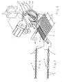
- Figure 4 shows an entry side of the shed 6 arranged device with different rotary actuators. While to form the fabric strip 2 a first rotary edge cutter 12 is provided with integral rotary drive, so the rotary body 12a is the rotor of an electric motor actuator, the catch strip 3 is formed by means of a foreign-driven rotary body 13a (rotary drive 14).
- the drives of the two edge twisters 12, 13 are controlled by a drive control 15.
- a drive control 15 On the entry side of the shed 6, analogously to the arrival or withdrawal side of the shed 6, the ends of the set weft threads 4 are preferably held pneumatically stretched by a holding or stretching device 30 to the inlet into a spreading device, not shown.
- FIG. 5 shows a device as already shown in FIG.
- the ratio of the number of reversals of rotation of the rotary bodies 12a, 13a per section of fabric 31 is different from one, that is. not after each weft insertion is a reversal of the direction of rotation of the rotary body 12a, 13a.
- the ratio of the reversals of rotation of a device consisting of two rotary edge twisters 12, 13 for forming a fabric strip 2 and a catch strip 3 can be varied as desired for each fabric section 31, or that the variation can be freely programmed.
- Figure 6 shows Fangleisten threads 9, which form the ends of the weft threads 4 by means of Vollwooderabitatien to a catch strip 3 by rotation of the rotating body 13a in one direction.
- the catch strip 3 as well as in the fabric strip 2, the point of reversal of the direction of rotation is not visually recognizable. In the present example, therefore, it is not shown that a reversal of the rotational direction of the rotational body 13a has been carried out.
- FIG. 7 shows the leno threads 7, which in one direction form the ends of the weft threads 4 by means of rotation of the rotation body 12a into a fabric strip 2 by means of full-turn ties. Due to the free programming of the rotary edge twister 12, 13, taping variants for the weft threads 4 are conceivable, such as e.g. so-called binding misfires that are equally feasible in the fabric strip 2 and 3 in the catch bar.
- the technology known per se for producing a full-turn fabric strip 2 can be used without restrictions for producing a temporary catch strip 3. It can further be seen that by the combination of two rotary edge twisters 12, 13 into one structural unit and using the full-turn technology, in addition to material savings for forming the catch strips 3, material savings per weft thread 4 can be achieved.
- the saving in weft material is made possible by the fact that, in particular on rapier weaving machines, the thread-indicating units and the weft scissors 17 can be positioned closer to the reed 27 by the reduced width of a conventionally produced catching strip 3. Further, it is thereby possible to set the start position of the weft insertion members (donor and taker grippers) closer to the reed 27.
Landscapes
- Engineering & Computer Science (AREA)
- Textile Engineering (AREA)
- Looms (AREA)
- Auxiliary Weaving Apparatuses, Weavers' Tools, And Shuttles (AREA)
- Treatment Of Fiber Materials (AREA)
- Woven Fabrics (AREA)
- Paper (AREA)
Claims (13)
- Procédé pour fabriquer un tissu (1) avec des lisières de tissu (2) et au moins une lisière de retenue (3) temporairement présente sur des métiers à tisser, selon lequel au moins un fil de trame (4) est inséré dans une foule (6) constituée de fils de chaîne (5), dans un pas de lisière de tissu (8) constitué de fils de tour (7) et dans un pas de lisière de retenue (10) constitué de fils de la lisière de retenue (9), à la suite de quoi le fil de trame (4) est appliqué contre la bordure d'arrêt (1a, 2a, 3a) du tissu (1), de la lisière de tissu (2) et de la lisière de retenue (3), puis passé par les fils de chaîne (5), les fils de tour (7) et les fils de la lisière de retenue (9) et ensuite séparé d'un fil de trame (4) déjà préparé au moyen d'au moins un ciseau pour fil de trame (17), la lisière de tissu (2) et la lisière de retenue (3) étant formées chacune comme une bordure à tour complet par rotation de corps rotatif (12a, 13a) guidant les fils de tour (7) et les fils de la lisière de retenue (9) d'un premier et second mécanisme rotatif pour lisières pas de gaze (12, 13) avec réversibilité du sens de rotation commandée, caractérisé en ce que les corps rotatifs (12a, 13a) sont entraînés et commandés indépendamment de l'entraînement du métier à tisser et en ce que la rotation et la réversibilité du sens de rotation de chaque corps rotatif (12a, 13a) sont librement programmables, sur le côté de prise ou d'entrée des fils de trame de la foule (6), une avance Δα du corps rotatif (13a) guidant les fils de la lisière de retenue (9) vis-à-vis du corps rotatif (12a) guidant les fils de tour (7) étant librement programmable, à la suite de quoi le pas de lisière de retenue (10) est fermé lors d'une avance Δα de plusieurs degrés devant le pas de lisière de tissu (8) et cette avance Δα est maintenue lors de l'inversion du sens de rotation.
- Procédé pour fabriquer un tissu (1) avec des lisières de tissu (2) et au moins une lisière de retenue (3) temporairement présente sur des métiers à tisser, selon lequel au moins un fil de trame (4) est inséré dans une foule (6) constituée de fils de chaîne (5), dans un pas de lisière de tissu (8) constitué de fils de tour (7) et dans un pas de lisière de retenue (10) constitué de fils de la lisière de retenue (9), à la suite de quoi le fil de trame (4) est appliqué contre la bordure d'arrêt (1a, 2a, 3a) du tissu (1), de la lisière de tissu (2) et de la lisière de retenue (3), puis passé par les fils de chaîne (5), les fils de tour (7) et les fils de la lisière de retenue (9) et ensuite séparé d'un fil de trame (4) déjà préparé au moyen d'au moins un ciseau pour fil de trame (17), la lisière de tissu (2) et la lisière de retenue (3) étant formées chacune comme une bordure à tour complet par rotation de corps rotatifs (12a, 13a) guidant les fils de tour (7) et les fils de la lisière de retenue (9) d'un premier et d'un second mécanisme rotatif pour lisières pas de gaze (12, 13) sans réversibilité du sens de rotation et les fils de tour (7) ainsi que les fils de la lisière de retenue (9) étant déroulés des bobines disposées sur un support entraîné par rotation,
caractérisé en ce que
les corps rotatifs (12a, 13a) sont entraînés et commandés indépendamment de l'entraînement du métier à tisser et en ce que la rotation de chaque corps rotatif (12a, 13a) est librement programmable, sur le côté de prise ou d'entrée des fils de trame de la foule (6), une avance Δα du corps rotatif (13a) guidant les fils de la lisière de retenue (9) vis-à-vis du corps rotatif (12a) guidant les fils de tour (7) étant librement programmable, à la suite de quoi le pas de lisière de retenue (10) est fermé lors d'une avance Δα de plusieurs degrés devant le pas de lisière de tissu (8). - Dispositif destiné à l'exécution du procédé selon la revendication 1 présentant:un premier mécanisme rotatif pour lisières pas de gaze (12) avec un corps rotatif (12a) guidant des fils de tour (7) pour former une lisière de tissu (2), un second mécanisme rotatif pour lisières pas de gaze (13) avec un corps rotatif (13a) guidant des fils de la lisière de retenue (9) pour former une lisière de retenue (3), les lisières de tissu et de retenue (2,3) pouvant être fabriquées par des armures de gaze à tour complet des fils à trame (4) au moyen de la réversibilité du sens de rotation commandée des corps rotatifs (12, 13),caractérisé en ce quechaque corps rotatif (12a, 13a) dispose d'un mécanisme d'entraînement rotatif (14) qui est indépendant de l'entraînement principal du métier à tisser et en ce que les deux mécanismes d'entraînement rotatif (14) peuvent être commandés indépendamment l'un de l'autre, sur le côté de prise ou d'entrée des fils de trame de la foule (6) une avance Δα du corps rotatif (13a) guidant les fils de la lisière de retenue (9) vis-à-vis du corps rotatif (12a) guidant les fils de tour (7) étant librement programmable, à la suite de quoi le pas de lisière de retenue (10) est fermé lors d'une avance Δα de plusieurs degrés devant le pas de lisière de tissu (8) et cette avance Δα est maintenue lors de l'inversion du sens de rotation.
- Dispositif destiné à l'exécution du procédé selon la revendication 2 comportant :a) un premier mécanisme rotatif pour lisières pas de gaze (12) avec un corps rotatif (12a) guidant des fils de tour (7) pour former une lisière de tissu (2),b) un second mécanisme rotatif pour lisières pas de gaze (13) avec un corps rotatif (13a) guidant des fils de la lisière de retenue (9) pour former une lisière de retenue (3)c) les lisières de tissu et de retenue (2, 3) pouvant être fabriquées par des armures de gaze à tour complet des fils à trame (4) sans réversibilité du sens de rotation des corps rotatifs (12a, 13a) etd) un support entraîné par rotation avec des bobines pour les fils à tour et les fils de lisière de retenue,caractérisé en ce que
chaque corps rotatif (12a, 13a) dispose d'un mécanisme d'entraînement rotatif (14) qui est indépendant de l'entraînement principal du métier à tisser et en ce que les deux mécanismes d'entraînement rotatif (14) peuvent être commandés indépendamment l'un de l'autre, sur le côté de prise ou d'entrée des fils de trame de la foule (6) une avance Δα du corps rotatif (13a) guidant les fils de la lisière de retenue (9) vis-à-vis du corps rotatif (12a) guidant les fils de tour (7) étant librement programmable, à la suite de quoi le pas de lisière de retenue (10) est fermé lors d'une avance Δα de plusieurs degrés devant le pas de lisière de tissu (8). - Dispositif selon l'une des revendications 3 ou 4, caractérisé en ce que le premier et le second mécanisme rotatif pour lisières pas de gaze (12, 13) constituent ensemble une unité structurelle sous la forme d'un système modulaire.
- Dispositif selon l'une des revendications 3 à 5, caractérisé en ce que chaque corps rotatif (12a, 13a) est formé comme un disque de mécanisme de torsion de préférence en forme d'anneau et dispose d'oeillets de guidage de fils (12b, 13b).
- Dispositif selon l'une des revendications 3 à 6, caractérisé en ce que au moins l'un des deux corps rotatifs (12a, 13a) est le rotor d'un servomoteur électrique.
- Dispositif selon la revendication 3, caractérisé en ce que selon la pièce de tissu ou la succession de duites, le nombre et les moments d'inversion du sens de rotation ainsi que le nombre de rotations de chaque corps rotatif (12a, 13a) peuvent être librement programmés au moyen d'une commande à entraînement (15).
- Dispositif selon la revendication 4, caractérisé en ce que selon la pièce de tissu ou la succession de duites, le nombre de rotations de chaque corps rotatif (12a, 13a) peut être librement programmé au moyen d'une commande à entraînement (15).
- Dispositif selon la revendication 5, caractérisé en ce que l'unité structurelle formée par les mécanismes rotatifs pour lisières pas de gaze (12, 13) peut être déplacée au moyen d'un dispositif de support (22) au sein du métier à tisser.
- Dispositif selon la revendication 10, caractérisé par un dispositif de support (22) aux caractéristiques suivantes:a)au moins un premier composant (22a) pouvant être fixé au métier et réglé d'au moins un niveau,b) au moins un deuxième et troisième composants (22b, 22c) reliés au premier composant (22a), le troisième composant (22c) étant disposé de sorte à pouvoir pivoter seulement d'un niveau autour d'un axe vertical (23) etc) l'unité structurelle étant reliée au troisième composant (22c) de sorte que l'unité peut être décalée le long de l'axe central (24) du troisième composant (22c) et peut être pivotée autour de celui-ci.
- Dispositif selon la revendication 11, caractérisé en ce que le premier et le second mécanismes rotatifs pour lisières pas de gaze (12, 13) de l'unité structurelle sont assemblés au troisième composant (22c) de sorte que leurs corps rotatifs (12a, 13a) pivotent autour d'un axe central commun (25).
- Dispositif selon la revendication 12, caractérisé en ce qu'en état de marche de l'unité structurelle, l'axe central (25) est à peu près parallèle à la bordure d'arrêt (1a, 2a, 3a) du tissu (1) de la lisière du tissu (2) et de la lisière de retenue (3).
Applications Claiming Priority (2)
| Application Number | Priority Date | Filing Date | Title |
|---|---|---|---|
| DE19720634A DE19720634C1 (de) | 1997-05-16 | 1997-05-16 | Verfahren zum Bilden einer Gewebe- und Fangleiste bei der Herstellung eines Gewebes auf Webmaschinen und Vorrichtung zur Durchführung des Verfahrens |
| DE19720634 | 1997-05-16 |
Publications (2)
| Publication Number | Publication Date |
|---|---|
| EP0878570A1 EP0878570A1 (fr) | 1998-11-18 |
| EP0878570B1 true EP0878570B1 (fr) | 2007-05-23 |
Family
ID=7829702
Family Applications (1)
| Application Number | Title | Priority Date | Filing Date |
|---|---|---|---|
| EP98107341A Revoked EP0878570B1 (fr) | 1997-05-16 | 1998-04-22 | Procédé pour former un tissu avec des lisières et au moins une lisière de retenue sur métiers à tisser ainsi que dispositif pour la mise en oeuvre de ce procédé |
Country Status (12)
| Country | Link |
|---|---|
| US (1) | US5996647A (fr) |
| EP (1) | EP0878570B1 (fr) |
| JP (1) | JP2933915B2 (fr) |
| KR (1) | KR100316869B1 (fr) |
| CN (1) | CN1201038C (fr) |
| AT (1) | ATE363002T1 (fr) |
| BR (1) | BR9804911A (fr) |
| CZ (1) | CZ294030B6 (fr) |
| DE (2) | DE19720634C1 (fr) |
| ID (1) | ID21959A (fr) |
| TR (1) | TR199802677T1 (fr) |
| WO (1) | WO1998053129A1 (fr) |
Families Citing this family (24)
| Publication number | Priority date | Publication date | Assignee | Title |
|---|---|---|---|---|
| DE19716349C1 (de) * | 1997-04-18 | 1998-06-10 | Kloecker Entwicklungs Gmbh | Antriebseinheit für eine Welle einer synchron zu den Schäften einer Webmaschine arbeitenden Vorrichtung zum Bilden einer Dreherkante |
| ITMI991221A1 (it) * | 1999-05-31 | 1999-08-31 | Somet Soc Mec Tessile | Dispositivo e metodo per la formazione della cimosa in un telaio di te ssitura |
| KR20040053625A (ko) * | 2002-12-17 | 2004-06-24 | 백경태 | 샷틀리스 직기용 캣치코드사 개구장치 |
| DE10307489B3 (de) * | 2003-02-21 | 2004-11-11 | Lindauer Dornier Gesellschaft Mbh | Verfahren zum Herstellen eines Gewebes in Leinwand- und Dreherbindungen sowie Webmaschine zur Verfahrensdurchführung |
| DE10313188A1 (de) * | 2003-03-25 | 2004-10-07 | Lindauer Dornier Gmbh | Rotationskantendrehereinrichtung einer Webmaschine |
| DE10336006B4 (de) * | 2003-08-01 | 2007-07-12 | Lindauer Dornier Gesellschaft Mit Beschränkter Haftung | Vorrichtung an einer Webmaschine zum Bilden von Dreherkanten |
| DE102005022955A1 (de) * | 2005-05-19 | 2006-11-23 | Lindauer Dornier Gmbh | Verfahren und Vorrichtung zum Halten eines nach einem Startvorgang einer Webmaschine, insbesondere Luftdüsenwebmaschine eingetragenen Schussfadens |
| DE102006025265A1 (de) | 2006-05-31 | 2007-12-06 | Lindauer Dornier Gmbh | Verfahren und Vorrichtung zum Bilden einer Gewebekante an einer Greiferwebmaschine |
| JP2010111980A (ja) * | 2008-11-10 | 2010-05-20 | Abedesignpro Co Ltd | 織物製品及びその製造方法 |
| EP2807299B1 (fr) * | 2012-01-24 | 2025-10-22 | NIKE Innovate C.V. | Dispositif de finissage de tissage |
| CN104126041B (zh) | 2012-01-24 | 2017-10-10 | 耐克创新有限合伙公司 | 多层编织 |
| CN104114473B (zh) * | 2012-01-24 | 2017-03-15 | 耐克创新有限合伙公司 | 间歇编织接合器 |
| DE102012009420A1 (de) | 2012-05-11 | 2013-11-14 | Gebrüder Klöcker GmbH | Vorrichtung zum Herstellen eines Gewebes |
| JP6071391B2 (ja) * | 2012-06-13 | 2017-02-01 | 津田駒工業株式会社 | 織機の耳形成装置 |
| JP5671102B2 (ja) * | 2013-06-27 | 2015-02-18 | アベデザインプロ株式会社 | 織物製品の製造方法 |
| CN103334209B (zh) * | 2013-07-19 | 2015-10-28 | 安徽丹凤集团桐城玻璃纤维有限公司 | 带有助纱装置的玻璃纤维喷气织机 |
| JP6256350B2 (ja) * | 2013-09-17 | 2018-01-10 | 東レ株式会社 | 織機および織物の製造方法 |
| GB2571563B (en) * | 2018-03-01 | 2023-01-04 | Dewhurst James Ltd | Woven textile and associated method of manufacture |
| CN108330588A (zh) * | 2018-03-05 | 2018-07-27 | 浙江理工大学 | 利用低熔点涤纶热熔丝加固织造废边的方法 |
| CN109402829A (zh) * | 2018-11-12 | 2019-03-01 | 山东日发纺织机械有限公司 | 电子绞边机构 |
| IT201900014982A1 (it) * | 2019-08-23 | 2021-02-23 | Santex Rimar Group S R L | Dispositivo per il risparmio della trama in macchine per tessere |
| CN111304822B (zh) * | 2020-03-24 | 2024-04-19 | 江苏百宏复合材料科技股份有限公司 | 一种双褶边夜光驱蚊弹性带及其制造方法 |
| JP7518035B2 (ja) * | 2021-05-10 | 2024-07-17 | 津田駒工業株式会社 | 織機の耳糸開口装置 |
| CN116288853B (zh) * | 2022-09-08 | 2025-07-15 | 山东金号家纺集团有限公司 | 一种防止毛巾内边脱落的绞边编织装置 |
Family Cites Families (12)
| Publication number | Priority date | Publication date | Assignee | Title |
|---|---|---|---|---|
| DE836475C (de) * | 1947-03-08 | 1952-04-15 | Sulzer Ag | Verfahren und Vorrichtung zum Binden von Kanten an Geweben |
| BE757324A (fr) * | 1969-10-09 | 1971-04-09 | Interbrev Sa | Procede de fabrication d'un ruban a lisiere a boucles saillantes, metier a aiguille mettant en oeuvre ce procede et ruban obtenu par ce procede, notamment ruban pour fermeture a glissiere |
| US3952778A (en) * | 1975-04-28 | 1976-04-27 | Rockwell International Corporation | Selvage forming device |
| CH621158A5 (fr) * | 1977-05-13 | 1981-01-15 | Rueti Ag Maschf | |
| US4421141A (en) * | 1979-08-06 | 1983-12-20 | Leesona Corporation | Fabric selvage forming |
| ATE3069T1 (de) * | 1979-08-16 | 1983-04-15 | Gebrueder Sulzer Aktiengesellschaft | Dreherfaden-liefereinrichtung fuer eine webmaschine. |
| JPS5771459A (en) * | 1980-10-15 | 1982-05-04 | Toyoda Automatic Loom Works | Abnormality detecting apparatus of ear yarn in ear molding apparatus of loom |
| IT1255133B (it) * | 1992-05-05 | 1995-10-20 | Luciano Corain | Perfezionamento in un telaio tessile senza navetta |
| US5392819A (en) * | 1993-12-10 | 1995-02-28 | Hunshin Enterprise Co., Ltd. | Planetary gear type selvage forming and cord catching device for loom |
| DE59502454D1 (de) * | 1994-02-23 | 1998-07-16 | Dornier Gmbh Lindauer | Rotations-Kantendreher für Webmaschinen |
| DE4405777C2 (de) * | 1994-02-23 | 2002-03-07 | Dornier Gmbh Lindauer | Rotations-Kantendreher einer Webmaschine |
| DE4405776C1 (de) * | 1994-02-23 | 1995-08-17 | Dornier Gmbh Lindauer | Rotations-Kantendreher einer Webmaschine |
-
1997
- 1997-05-16 DE DE19720634A patent/DE19720634C1/de not_active Revoked
-
1998
- 1998-04-22 DE DE59814010T patent/DE59814010D1/de not_active Revoked
- 1998-04-22 EP EP98107341A patent/EP0878570B1/fr not_active Revoked
- 1998-04-22 AT AT98107341T patent/ATE363002T1/de not_active IP Right Cessation
- 1998-04-29 KR KR1019997000432A patent/KR100316869B1/ko not_active Expired - Fee Related
- 1998-04-29 BR BR9804911-9A patent/BR9804911A/pt not_active IP Right Cessation
- 1998-04-29 ID IDW990028D patent/ID21959A/id unknown
- 1998-04-29 TR TR1998/02677T patent/TR199802677T1/xx unknown
- 1998-04-29 CN CNB988009722A patent/CN1201038C/zh not_active Expired - Fee Related
- 1998-04-29 WO PCT/DE1998/001185 patent/WO1998053129A1/fr not_active Ceased
- 1998-04-29 CZ CZ1999122A patent/CZ294030B6/cs not_active IP Right Cessation
- 1998-05-08 JP JP10125887A patent/JP2933915B2/ja not_active Expired - Fee Related
- 1998-05-13 US US09/078,338 patent/US5996647A/en not_active Expired - Fee Related
Also Published As
| Publication number | Publication date |
|---|---|
| TR199802677T1 (xx) | 1999-07-21 |
| JP2933915B2 (ja) | 1999-08-16 |
| WO1998053129A1 (fr) | 1998-11-26 |
| JPH10325045A (ja) | 1998-12-08 |
| BR9804911A (pt) | 2000-01-25 |
| KR100316869B1 (ko) | 2001-12-24 |
| KR20000023847A (ko) | 2000-04-25 |
| CN1201038C (zh) | 2005-05-11 |
| ID21959A (id) | 1999-08-19 |
| CN1234841A (zh) | 1999-11-10 |
| US5996647A (en) | 1999-12-07 |
| DE59814010D1 (de) | 2007-07-05 |
| ATE363002T1 (de) | 2007-06-15 |
| CZ294030B6 (cs) | 2004-09-15 |
| EP0878570A1 (fr) | 1998-11-18 |
| DE19720634C1 (de) | 1998-10-01 |
| CZ12299A3 (cs) | 1999-06-16 |
Similar Documents
| Publication | Publication Date | Title |
|---|---|---|
| EP0878570B1 (fr) | Procédé pour former un tissu avec des lisières et au moins une lisière de retenue sur métiers à tisser ainsi que dispositif pour la mise en oeuvre de ce procédé | |
| EP0043441B2 (fr) | Procédé et dispositif pour réaliser une jointure tissée comme liaison entre deux bouts de tissu | |
| EP2004889B1 (fr) | Sangle, procédé et métier à tisser à aiguilles pour la rubanerie destinés à la production de cette bande | |
| EP0674031B1 (fr) | Mécanisme rotatif pour lisières "pas de gaze" pour métier à tisser | |
| EP1395692B1 (fr) | Metier a tisser destine a la production d'un tissu en gaze | |
| WO1997024479A1 (fr) | Dispositif pour former une lisiere a point de gaze, notamment pour metier a tisser sans navette | |
| DE2845299A1 (de) | Schuetzenlose webmaschine | |
| EP0875610B1 (fr) | Dispositif pour la formation d'une lisière à pas de gaze, en particulier pour métiers à tisser | |
| EP0674032B2 (fr) | Mécanisme rotatif pour lisières "pas de gaze" pour métier à tisser | |
| EP1272699B1 (fr) | Procede pour le reglage de parametres de tissage pour des metiers mecaniques et dispositif de commande | |
| DE29708758U1 (de) | Webmaschine | |
| EP0918103B1 (fr) | Procédé et dispositif pour obtenir des déchets de fil de trame purs des lisières de retenue | |
| EP2662479B1 (fr) | Machine à tisser avec dispositifs pas de gaze | |
| DE2164948A1 (de) | Verfahren zum weben von doppel-florgeweben | |
| EP0681044A1 (fr) | Procédé et dispositif pour évacuer les déchets de faux lisières | |
| EP0973965A1 (fr) | Metier a tisser avec insertion pneumatique du fil de trame | |
| DE10336006B4 (de) | Vorrichtung an einer Webmaschine zum Bilden von Dreherkanten | |
| EP1899516B1 (fr) | Procede et dispositif pour maintenir un fil de trame introduit dans un metier apres sa mise en marche, notamment dans un metier a jet d'air | |
| DE3105965A1 (de) | Webmaschine | |
| DE1941404B2 (de) | Ein- und Ausfädelvorrichtung einer Greiferschützenwebmaschine | |
| EP0350574B1 (fr) | Machine pour fabriquer une liaison sans fin d'une bande de tissu. | |
| DE19743612C2 (de) | Verfahren und Vorrichtung zum Erzeugen von sortenreinem Schußfadenabfall aus Fangleisten | |
| WO2009030196A1 (fr) | Procédé et dispositif permettant d'éliminer, dans des tissus, des fils de trame présentant des irrégularités | |
| WO2001059192A1 (fr) | Procede pour devier une portee de fils de chaine pendant le tissage, et metier a tisser | |
| DE2935558C2 (de) | Verfahren und Vorrichtung zum Arbeiten auf schützenlosen Webmaschinen. |
Legal Events
| Date | Code | Title | Description |
|---|---|---|---|
| PUAI | Public reference made under article 153(3) epc to a published international application that has entered the european phase |
Free format text: ORIGINAL CODE: 0009012 |
|
| AK | Designated contracting states |
Kind code of ref document: A1 Designated state(s): AT BE CH DE ES FR GB IE IT LI NL PT SE |
|
| AX | Request for extension of the european patent |
Free format text: AL;LT;LV;MK;RO;SI |
|
| 17P | Request for examination filed |
Effective date: 19990113 |
|
| AKX | Designation fees paid |
Free format text: BE CH DE FR GB IT LI |
|
| RBV | Designated contracting states (corrected) |
Designated state(s): AT BE CH DE ES FR GB IE IT LI NL PT SE |
|
| 17Q | First examination report despatched |
Effective date: 20010928 |
|
| 17Q | First examination report despatched |
Effective date: 20010928 |
|
| GRAP | Despatch of communication of intention to grant a patent |
Free format text: ORIGINAL CODE: EPIDOSNIGR1 |
|
| RTI1 | Title (correction) |
Free format text: METHOD FOR FORMING A FABRIC WITH SELVEDGES AND AT LEAST ONE CATCH SELVEDGE ON LOOMS AND DEVICE FOR CARRYING OUT THIS METHOD |
|
| GRAS | Grant fee paid |
Free format text: ORIGINAL CODE: EPIDOSNIGR3 |
|
| GRAA | (expected) grant |
Free format text: ORIGINAL CODE: 0009210 |
|
| AK | Designated contracting states |
Kind code of ref document: B1 Designated state(s): AT BE CH DE ES FR GB IE IT LI NL PT SE |
|
| REG | Reference to a national code |
Ref country code: GB Ref legal event code: FG4D Free format text: NOT ENGLISH |
|
| REG | Reference to a national code |
Ref country code: CH Ref legal event code: EP |
|
| REG | Reference to a national code |
Ref country code: IE Ref legal event code: FG4D Free format text: LANGUAGE OF EP DOCUMENT: GERMAN |
|
| REF | Corresponds to: |
Ref document number: 59814010 Country of ref document: DE Date of ref document: 20070705 Kind code of ref document: P |
|
| REG | Reference to a national code |
Ref country code: CH Ref legal event code: NV Representative=s name: R. A. EGLI & CO. PATENTANWAELTE |
|
| PG25 | Lapsed in a contracting state [announced via postgrant information from national office to epo] |
Ref country code: SE Free format text: LAPSE BECAUSE OF FAILURE TO SUBMIT A TRANSLATION OF THE DESCRIPTION OR TO PAY THE FEE WITHIN THE PRESCRIBED TIME-LIMIT Effective date: 20070823 |
|
| PG25 | Lapsed in a contracting state [announced via postgrant information from national office to epo] |
Ref country code: ES Free format text: LAPSE BECAUSE OF FAILURE TO SUBMIT A TRANSLATION OF THE DESCRIPTION OR TO PAY THE FEE WITHIN THE PRESCRIBED TIME-LIMIT Effective date: 20070903 |
|
| GBT | Gb: translation of ep patent filed (gb section 77(6)(a)/1977) |
Effective date: 20070926 |
|
| NLV1 | Nl: lapsed or annulled due to failure to fulfill the requirements of art. 29p and 29m of the patents act | ||
| ET | Fr: translation filed | ||
| REG | Reference to a national code |
Ref country code: IE Ref legal event code: FD4D |
|
| PG25 | Lapsed in a contracting state [announced via postgrant information from national office to epo] |
Ref country code: PT Free format text: LAPSE BECAUSE OF FAILURE TO SUBMIT A TRANSLATION OF THE DESCRIPTION OR TO PAY THE FEE WITHIN THE PRESCRIBED TIME-LIMIT Effective date: 20071023 Ref country code: NL Free format text: LAPSE BECAUSE OF FAILURE TO SUBMIT A TRANSLATION OF THE DESCRIPTION OR TO PAY THE FEE WITHIN THE PRESCRIBED TIME-LIMIT Effective date: 20070523 Ref country code: IE Free format text: LAPSE BECAUSE OF FAILURE TO SUBMIT A TRANSLATION OF THE DESCRIPTION OR TO PAY THE FEE WITHIN THE PRESCRIBED TIME-LIMIT Effective date: 20070523 |
|
| PLBI | Opposition filed |
Free format text: ORIGINAL CODE: 0009260 |
|
| PLBI | Opposition filed |
Free format text: ORIGINAL CODE: 0009260 |
|
| 26 | Opposition filed |
Opponent name: GEBRUEDER KLOECKER GMBH Effective date: 20080215 |
|
| PLAX | Notice of opposition and request to file observation + time limit sent |
Free format text: ORIGINAL CODE: EPIDOSNOBS2 |
|
| 26 | Opposition filed |
Opponent name: GEBRUEDER KLOECKER GMBH Effective date: 20080215 Opponent name: PICANOL N.V. Effective date: 20080221 |
|
| RDAF | Communication despatched that patent is revoked |
Free format text: ORIGINAL CODE: EPIDOSNREV1 |
|
| PGFP | Annual fee paid to national office [announced via postgrant information from national office to epo] |
Ref country code: DE Payment date: 20080313 Year of fee payment: 11 |
|
| PLAB | Opposition data, opponent's data or that of the opponent's representative modified |
Free format text: ORIGINAL CODE: 0009299OPPO |
|
| PLBB | Reply of patent proprietor to notice(s) of opposition received |
Free format text: ORIGINAL CODE: EPIDOSNOBS3 |
|
| PGFP | Annual fee paid to national office [announced via postgrant information from national office to epo] |
Ref country code: IT Payment date: 20080415 Year of fee payment: 11 Ref country code: BE Payment date: 20080403 Year of fee payment: 11 |
|
| RDAG | Patent revoked |
Free format text: ORIGINAL CODE: 0009271 |
|
| STAA | Information on the status of an ep patent application or granted ep patent |
Free format text: STATUS: PATENT REVOKED |
|
| PGFP | Annual fee paid to national office [announced via postgrant information from national office to epo] |
Ref country code: CH Payment date: 20080725 Year of fee payment: 11 |
|
| REG | Reference to a national code |
Ref country code: CH Ref legal event code: PL |
|
| 27W | Patent revoked |
Effective date: 20080714 |
|
| GBPR | Gb: patent revoked under art. 102 of the ep convention designating the uk as contracting state |
Effective date: 20080714 |
|
| PGFP | Annual fee paid to national office [announced via postgrant information from national office to epo] |
Ref country code: FR Payment date: 20080317 Year of fee payment: 11 |
|
| PGFP | Annual fee paid to national office [announced via postgrant information from national office to epo] |
Ref country code: GB Payment date: 20080408 Year of fee payment: 11 |