EP0878570B1 - Method for forming a fabric with selvedges and at least one catch selvedge on looms and device for carrying out this method - Google Patents
Method for forming a fabric with selvedges and at least one catch selvedge on looms and device for carrying out this method Download PDFInfo
- Publication number
- EP0878570B1 EP0878570B1 EP98107341A EP98107341A EP0878570B1 EP 0878570 B1 EP0878570 B1 EP 0878570B1 EP 98107341 A EP98107341 A EP 98107341A EP 98107341 A EP98107341 A EP 98107341A EP 0878570 B1 EP0878570 B1 EP 0878570B1
- Authority
- EP
- European Patent Office
- Prior art keywords
- selvedge
- threads
- catch
- fabric
- leno
- Prior art date
- Legal status (The legal status is an assumption and is not a legal conclusion. Google has not performed a legal analysis and makes no representation as to the accuracy of the status listed.)
- Revoked
Links
- 239000004744 fabric Substances 0.000 title claims abstract description 84
- 238000000034 method Methods 0.000 title claims description 16
- 238000004519 manufacturing process Methods 0.000 claims description 8
- 238000010276 construction Methods 0.000 claims description 6
- 238000005520 cutting process Methods 0.000 claims description 4
- 230000007246 mechanism Effects 0.000 claims 9
- 238000004795 WEFT sequence Methods 0.000 claims 2
- 238000009941 weaving Methods 0.000 abstract description 13
- 241001589086 Bellapiscis medius Species 0.000 description 18
- 239000000463 material Substances 0.000 description 9
- 238000003780 insertion Methods 0.000 description 5
- 230000037431 insertion Effects 0.000 description 5
- 235000014676 Phragmites communis Nutrition 0.000 description 4
- 230000008901 benefit Effects 0.000 description 4
- 230000015572 biosynthetic process Effects 0.000 description 4
- 239000002699 waste material Substances 0.000 description 3
- 230000009471 action Effects 0.000 description 2
- 238000005516 engineering process Methods 0.000 description 2
- 230000008439 repair process Effects 0.000 description 2
- 238000000926 separation method Methods 0.000 description 2
- 229920002994 synthetic fiber Polymers 0.000 description 2
- 230000000454 anti-cipatory effect Effects 0.000 description 1
- 230000008859 change Effects 0.000 description 1
- 230000002950 deficient Effects 0.000 description 1
- 230000001419 dependent effect Effects 0.000 description 1
- 230000006866 deterioration Effects 0.000 description 1
- 230000006872 improvement Effects 0.000 description 1
- 230000014759 maintenance of location Effects 0.000 description 1
- 230000003287 optical effect Effects 0.000 description 1
- 210000000056 organ Anatomy 0.000 description 1
- 230000035515 penetration Effects 0.000 description 1
- 230000000737 periodic effect Effects 0.000 description 1
- 230000002093 peripheral effect Effects 0.000 description 1
- 230000008569 process Effects 0.000 description 1
- 230000007480 spreading Effects 0.000 description 1
- 238000003892 spreading Methods 0.000 description 1
- 230000001360 synchronised effect Effects 0.000 description 1
- 230000007704 transition Effects 0.000 description 1
- 230000000007 visual effect Effects 0.000 description 1
- 210000002268 wool Anatomy 0.000 description 1
- 238000010626 work up procedure Methods 0.000 description 1
Images


Classifications
-
- D—TEXTILES; PAPER
- D03—WEAVING
- D03C—SHEDDING MECHANISMS; PATTERN CARDS OR CHAINS; PUNCHING OF CARDS; DESIGNING PATTERNS
- D03C7/00—Leno or similar shedding mechanisms
- D03C7/04—Mechanisms having discs oscillating about a weftwise axis and having apertures for warp threads
-
- D—TEXTILES; PAPER
- D03—WEAVING
- D03D—WOVEN FABRICS; METHODS OF WEAVING; LOOMS
- D03D47/00—Looms in which bulk supply of weft does not pass through shed, e.g. shuttleless looms, gripper shuttle looms, dummy shuttle looms
- D03D47/40—Forming selvedges
Definitions
- the invention relates to methods for producing a fabric with fabric strips and at least one temporarily existing catch strip on weaving machines according to the preambles of claims 1 and 2. Such methods are known from GB-A-669 196.
- a rotary edge cutter is provided for producing the fabric strips, which permanently remain on the fabric, and the catch strip, which is intended only to prevent the weft yarn from springing back into the shed and is separated after the weaving process has been completed .
- the two rotary edge rotators have disc-shaped rotating bodies which are arranged coaxially next to each other at the edges of the resulting fabric web in the region of the shed. The axis of rotation of the rotating body is perpendicular to the direction of the warp threads.
- the rotary bodies have in their peripheral area thread guide eyelets, through which the leno threads are passed to form the fabric strips or the Fangleisten threads to form the trap bar. It is expressly pointed out in GB-A-669 196 that the two rotary bodies can be operated either with controlled direction of rotation reversal or without reverse rotation. In the first case, the coils, from which the leno and Fangleisten threads are removed, may be arranged stationary; in the second case, it is necessary to store the coils on a rotary holder. In the preambles of claims 1 and 2 of the present application these two cases are taken into account.
- GB-A-669 196 contains no information about how the drive of the two bodies of revolution should be realized constructively. After the age of this document, however, it can be assumed that the drive is derived mechanically from the main drive of the loom. This must necessarily mean that the two rotary edgebanders operate at a common speed, which is set once in the design of the loom, and that also the phases of the periodic change from forward to reverse rotation can be subsequently changed only with great effort. Furthermore, the possible speed of the conventionally driven rotary edger is not very high, so that they are limited in modern, high-speed running weaving machines.
- rotary edge knives are already known, which are driven independently of the main drive of the loom by its own electric motor. Such a rotary edge cutter can be individually controlled and programmed. This applies, for example, to certain phases of forward and reverse rotation or to the selective setting of single bonds and bond misfires.
- the rotary edge twisters according to DE-A-44 05 776 and DE-A-44 05 777 have been proposed for forming the fabric strips or fabric edges on high-speed modern weaving machines and have proven themselves.
- a further disadvantage is that in the multi-filament crosswheels the Fangleisten threads are mechanically stressed very high, especially by deflections of the threads. It is therefore necessary to use safety catch threads of a tear-resistant material, for example of a synthetic material.
- the Fangmann then consists of natural weft yarn, while the applied as Vollcarderitati Fangleisten threads made of a synthetic yarn.
- a further disadvantage is that in the case of an automatic weft breakage repair, which requires reopening (reverse weaving) of the previously closed shed, the catch wedge compartment setting the defective weft thread is not always released. Then, the weft breakage repair can not be performed in the required short time.
- the invention is therefore based on the object to improve the aforementioned method with and without reversing the rotational body so that the high weaving speeds of modern weaving machines are achieved, at the same time the material used for the catch strips is reduced, the weft threads on both sides of the fabric reliable be held and yet after the separation of the catch strips a high quality, durable fabric strip of beautiful visual effect comes about.
- catch strips no longer have to be as wide as when using the conventional edge twister or in canvas binding catch strips, also required for the catch strips end portions of the weft threads are shorter and also achieved a material savings in the weft threads.
- GNeillrvebmaschinen it was possible to save by the new construction about 25mm weft material per shot.
- the lower mechanical stress of the Fangleisten threads by the present invention used according to the rotary edgers also leads to the fact that the Fangleisten threads in very many cases may consist of the same material as the weft threads, resulting in not only less, but also sorted waste.
- wool tethers may also be used, while in the manufacture of synthetic fabric, synthetic tuck yarns are used. Since the waste is sorted, all separated catch strips can be fed virtually a workup and reuse, which means a cost savings for the weaving.
- the base fabric and the fabric strip consist of the much finer warp threads and leno threads; Therefore, the shed and the fabric strip tray should be kept open as long as possible so that warp threads and leno threads are not disoriented or even damaged by the penetration of the weft thread, for example by touching the gripper.
- the flow .DELTA..alpha Of the rotation body leading the catch strip threads to the rotation body guiding the leno threads allows to fulfill the two opposing requirements, the fabric strip visible after the separation of the catch strips is not only of high quality but also of good optical effect. At the same time prevents the flow ⁇ in the edge formation, the "preliminary work" of the trap bar against the binding point of the shed, as given by the former shorts a better leno thread training.
- the invention also relates to the apparatus required for carrying out the method, which are specified in claims 3 and 4.
- the relevant and taken into account in the preambles of claims 3 and 4 prior art is again the GB-A-669 196th
- the device consists of a first rotary edge cutter 12 and of a second rotary edge cutter 13.
- the construction, the arrangement and the mode of action of both edge twisters are comprehensively described in DE 44 05 777 C1, so that at this point repetitions are described is waived.
- Each of the edge twisters 12, 13 has a leno threads 7 or a Fangleisten threads 9 leading rotary body 12a with not visible here Fadens Entrysösen 12b and a rotating body 13a with Fangleisten threads leading Fadenationsscher 13b.
- Both edge twisters 12, 13 are rotatably drivable with one rotary drive 14 in each case.
- the rotary actuators 14 are driven by a drive control 15.
- the means for forming the shed 6 are not shown here, because generally known.
- At least one weft thread 4 is entered from the entry side of the shed 6 to the arrival or withdrawal side by means of pneumatic or mechanical entry members.
- the here in the subjects 6, 8, 10 registered weft thread 4 is to hit by the reed 27 to the stop edge 1a, 2a of the fabric 1 and the fabric strip 2 and by the Hilfswebblatt 28 to the stop edge 3a of the catch strip 3 and to Bonding by the shedding organs on the side of the shed 6 held by the weft insertion member 26.
- the rotary bodies 12a, 13a are replaced by a multiplicity of successive half-turns, e.g. in which one direction of rotation, and preferably by the same multiplicity of successive half-turns in the other direction of rotation, form both the fabric strip 2 and the catch strips 3 as a fixed full-turn edge.
- the device shown here is arranged on the right side in the loom rotary edge twister 12 and 13; another device of the same construction is arranged on the left side in the weaving machine, as shown for example in FIGS. 4 and 5.
- At least one holding or stretching device 29, 30 is provided on both sides of the fabric 1.
- a fabric or cutting lane 16 is formed between the fabric strip 2 and the catch strip 3, see also Figure 4, in which a separator 17 engages and the catch strip at the appropriate time of the fabric. 1 separates.
- each rotary edge twister 12,13 of the device is equipped with its own rotary drive 14, it is possible, each rotary edge twister 12, 13 individually, especially with regard to the reversal of the direction of rotation and the time for setting the weft threads 4 to form the exhaust side fishing line 3, to control.
- the catch strip threads 9 for the catch strip 3 are, like the leno threads 7 for the fabric strip 2, withdrawn from holders 19 and 18 arranged on coils 21 and 20, wherein the holders 18,19 are mounted stationary.
- the coils 20, 21 are arranged on a, not shown, rotationally driven coil holder.
- a rotary-driven bobbin holder is required, first, to prevent any mutual wraps of the leno threads 7 and, secondly, no mutual wraps of the suture strip threads 9 on the path between the rotary bodies 12a, 13a and the coils 20, 21.
- the device consists of a first rotary edge cutter 12 and a second rotary edge cutter 13.
- the construction, arrangement and mode of action of both edge twisters are disclosed in DE 44 05 776 C1. It is essential here that both rotational bodies 12a, 13a are the rotors of an electromotive actuator.
- both edge twisters form a structural unit which is received by a carrying device 22.
- each edge twister 12,13 is individually controlled and operated in accordance with the shedding.
- the support device 22 as a whole can be connected via the elongated holes 22d by corresponding machine elements with the weaving machine and positioned in the direction of the double arrow 32.
- At least a second and third component 22b, 22c is connected to the first component 22a.
- the third component 22 c is arranged in a plane alone in the direction of the double arrow 33 about a vertical axis 23 pivotally.
- the combined to a structural unit rotary edge twister 12, 13 are connected to the third component 22c such that the unit along the center axis 24 of the component 22c slidably and about this central axis 24 is pivotable.
- FIG. 3 shows two rotational bodies 12a, 13a which can be rotated about the center axis 25 with thread guiding eyelets 12b, 13b.
- the rotary bodies 12a, 13a are formed according to the device according to FIG. 1 or 2.
- the catch strip pocket 10 sets the weft thread 4 by a few degrees of rotation ⁇ in front of the fabric strip pocket 8.
- the rotation of the rotation body 13b leads the rotation of the rotation body 12b both in the flow according to arrow 34 and after reversal of direction in the return according to arrow 35 ahead.
- the degree of anticipatory rotation i. the amount ⁇ , is freely programmable in the drive control 15.
- Figure 4 shows an entry side of the shed 6 arranged device with different rotary actuators. While to form the fabric strip 2 a first rotary edge cutter 12 is provided with integral rotary drive, so the rotary body 12a is the rotor of an electric motor actuator, the catch strip 3 is formed by means of a foreign-driven rotary body 13a (rotary drive 14).
- the drives of the two edge twisters 12, 13 are controlled by a drive control 15.
- a drive control 15 On the entry side of the shed 6, analogously to the arrival or withdrawal side of the shed 6, the ends of the set weft threads 4 are preferably held pneumatically stretched by a holding or stretching device 30 to the inlet into a spreading device, not shown.
- FIG. 5 shows a device as already shown in FIG.
- the ratio of the number of reversals of rotation of the rotary bodies 12a, 13a per section of fabric 31 is different from one, that is. not after each weft insertion is a reversal of the direction of rotation of the rotary body 12a, 13a.
- the ratio of the reversals of rotation of a device consisting of two rotary edge twisters 12, 13 for forming a fabric strip 2 and a catch strip 3 can be varied as desired for each fabric section 31, or that the variation can be freely programmed.
- Figure 6 shows Fangleisten threads 9, which form the ends of the weft threads 4 by means of Vollwooderabitatien to a catch strip 3 by rotation of the rotating body 13a in one direction.
- the catch strip 3 as well as in the fabric strip 2, the point of reversal of the direction of rotation is not visually recognizable. In the present example, therefore, it is not shown that a reversal of the rotational direction of the rotational body 13a has been carried out.
- FIG. 7 shows the leno threads 7, which in one direction form the ends of the weft threads 4 by means of rotation of the rotation body 12a into a fabric strip 2 by means of full-turn ties. Due to the free programming of the rotary edge twister 12, 13, taping variants for the weft threads 4 are conceivable, such as e.g. so-called binding misfires that are equally feasible in the fabric strip 2 and 3 in the catch bar.
- the technology known per se for producing a full-turn fabric strip 2 can be used without restrictions for producing a temporary catch strip 3. It can further be seen that by the combination of two rotary edge twisters 12, 13 into one structural unit and using the full-turn technology, in addition to material savings for forming the catch strips 3, material savings per weft thread 4 can be achieved.
- the saving in weft material is made possible by the fact that, in particular on rapier weaving machines, the thread-indicating units and the weft scissors 17 can be positioned closer to the reed 27 by the reduced width of a conventionally produced catching strip 3. Further, it is thereby possible to set the start position of the weft insertion members (donor and taker grippers) closer to the reed 27.
Landscapes
- Engineering & Computer Science (AREA)
- Textile Engineering (AREA)
- Looms (AREA)
- Auxiliary Weaving Apparatuses, Weavers' Tools, And Shuttles (AREA)
- Treatment Of Fiber Materials (AREA)
- Woven Fabrics (AREA)
- Paper (AREA)
Abstract
Description
Die Erfindung betrifft Verfahren zum Herstellen eines Gewebes mit Gewebeleisten und wenigstens einer zeitweilig vorhandenen Fangleiste auf Webmaschinen nach den Oberbegriffen der Ansprüche 1 und 2. Derartige Verfahren sind aus der GB-A-669 196 bekannt.The invention relates to methods for producing a fabric with fabric strips and at least one temporarily existing catch strip on weaving machines according to the preambles of
Gemäß der GB-A-669 196 ist zum Erzeugen der Gewebeleisten, die dauernd an dem Gewebe verbleiben, und der Fangleiste, die nur ein Zurückspringen des Schussfadens in das Webfach verhindern soll und nach Abschluss des Webvorganges abgetrennt wird, je ein Rotations-Kantendreher vorgesehen. Die beiden Rotations-Kantendreher haben scheibenförmige Rotationskörper, die gleichachsig nebeneinander an den Rändern der entstehenden Gewebebahn im Bereich des Webfaches angeordnet sind. Die Rotationsachse der Rotationskörper verläuft senkrecht zu der Richtung der Kettfäden.According to GB-A-669 196, a rotary edge cutter is provided for producing the fabric strips, which permanently remain on the fabric, and the catch strip, which is intended only to prevent the weft yarn from springing back into the shed and is separated after the weaving process has been completed , The two rotary edge rotators have disc-shaped rotating bodies which are arranged coaxially next to each other at the edges of the resulting fabric web in the region of the shed. The axis of rotation of the rotating body is perpendicular to the direction of the warp threads.
Die Rotationskörper haben in ihrem Umfangsbereich Fadenführungsösen, durch die die Dreherfäden zur Bildung der Gewebeleisten bzw. die Fangleistenfäden zur Bildung der Fangleiste hindurchgeführt sind. Ausdrücklich ist in der GB-A-669 196 hervorgehoben, dass die beiden Rotationskörper entweder mit gesteuerter Drehrichtungsumkehr oder ohne Drehrichtungsumkehr betrieben sein können. Im ersten Fall können die Spulen, von denen die Dreher- und Fangleistenfäden abgezogen werden, ortsfest angeordnet sein; im zweiten Fall ist es notwendig, die Spulen auf einem drehangetriebenen Halter zu lagern. In den Oberbegriffen der Ansprüche 1 und 2 der vorliegenden Anmeldung sind diese beiden Fälle berücksichtigt.The rotary bodies have in their peripheral area thread guide eyelets, through which the leno threads are passed to form the fabric strips or the Fangleisten threads to form the trap bar. It is expressly pointed out in GB-A-669 196 that the two rotary bodies can be operated either with controlled direction of rotation reversal or without reverse rotation. In the first case, the coils, from which the leno and Fangleisten threads are removed, may be arranged stationary; in the second case, it is necessary to store the coils on a rotary holder. In the preambles of
Die GB-A-669 196 enthält keine Angaben darüber, wie der Antrieb der beiden Rotationskörper konstruktiv verwirklicht werden soll. Nach dem Alter dieser Druckschrift ist jedoch davon auszugehen, dass der Antrieb mechanisch vom Hauptantrieb der Webmaschine abgeleitet ist. Das muss zwangsläufig bedeuten, dass die beiden Rotations-Kantendreher mit einer gemeinsamen Drehzahl arbeiten, die bei der Auslegung der Webmaschine einmal festgelegt wird, und dass auch die Phasen des periodischer Wechsels von Vorwärts- auf Rückwärtsdrehung nachträglich nur mit großem Aufwand verändert werden können. Ferner ist die mögliche Drehzahl der konventionell angetriebenen Rotations-Kantendreher nicht sehr hoch, so dass diese in modernen, hochtourig laufenden Webmaschinen nur begrenzt einsetzbar sind.GB-A-669 196 contains no information about how the drive of the two bodies of revolution should be realized constructively. After the age of this document, however, it can be assumed that the drive is derived mechanically from the main drive of the loom. This must necessarily mean that the two rotary edgebanders operate at a common speed, which is set once in the design of the loom, and that also the phases of the periodic change from forward to reverse rotation can be subsequently changed only with great effort. Furthermore, the possible speed of the conventionally driven rotary edger is not very high, so that they are limited in modern, high-speed running weaving machines.
Aus der DE-A-44 05 776 und der DE-A-44 05 777 sind auch schon Rotations-Kantendreher bekannt, die unabhängig vom Hauptantrieb der Webmaschine durch einen eigenen Elektromotor angetrieben werden. Ein derartiger Rotations-Kantendreher kann für sich einzeln angesteuert und programmiert werden. Das gilt zum Beispiel für bestimmte Phasen des Vorwärts- und Rückwärtslaufs oder zum gezielten Einstellen von Einfachbindungen und Bindungsaussetzern. Die Rotations-Kantendreher gemäß der DE-A-44 05 776 und der DE-A-44 05 777 wurden zur Ausbildung der Gewebeleisten oder Gewebekanten an hochtourigen modernen Webmaschinen vorgeschlagen und haben sich dabei bewährt.From DE-A-44 05 776 and DE-A-44 05 777 rotary edge knives are already known, which are driven independently of the main drive of the loom by its own electric motor. Such a rotary edge cutter can be individually controlled and programmed. This applies, for example, to certain phases of forward and reverse rotation or to the selective setting of single bonds and bond misfires. The rotary edge twisters according to DE-A-44 05 776 and DE-A-44 05 777 have been proposed for forming the fabric strips or fabric edges on high-speed modern weaving machines and have proven themselves.
Die Fangleisten wurden dagegen bisher entweder mit konventionellen Kantendrehern hergestellt wie z. B. Vierfaden-Kreuzdrehern, oder es wird mit leinwandbindigen Fangleistenfäden mit wenigstens 8 und bis zu 20 Fangleistenfäden auf jeder Gewebeleiste gearbeitet. Letzteres war bei der Mehrzahl der hochtourig laufenden Webmaschinen vorgesehen. Es wird also eine relativ breite und somit materialintensive Fangleiste produziert.The catch strips, however, have previously been produced either with conventional edge turners such. B. Vierfaden-Kreuzdrehern, or it is working with canvas binding Fangleisten threads with at least 8 and up to 20 Fangleisten threads on each fabric bar. The latter was provided in the majority of the high-speed weaving machines. So it is a relatively broad and thus material-intensive catch bar produced.
Nachteilig ist ferner, dass bei den Mehrfaden-Kreuzdrehern die Fangleistenfäden mechanisch sehr hoch beansprucht werden, vor allem durch Umlenkungen der Fäden. Man muss daher Fangleistenfäden aus einem reißfesten Material verwenden, z.B. aus einem synthetischen Material. Das bringt aber den Nachteil mit sich, dass die abgeschnittenen Fangleisten keinen sortenreinen Abfall bilden. Die Fangleiste besteht dann aus natürlichem Schussgarn, während die als Volldreherbindung aufgebrachten Fangleistenfäden aus einem synthetischen Garn bestehen. Außerdem besteht die Gefahr, dass die konventionellen Mehrfaden-Kreuzdreher bei den heute erforderlichen hohen Drehgeschwindigkeiten vorzeitig verschleißen.A further disadvantage is that in the multi-filament crosswheels the Fangleisten threads are mechanically stressed very high, especially by deflections of the threads. It is therefore necessary to use safety catch threads of a tear-resistant material, for example of a synthetic material. The But brings with it the disadvantage that the cut-off catch strips do not form a sorted waste. The Fangleiste then consists of natural weft yarn, while the applied as Volldreherbindung Fangleisten threads made of a synthetic yarn. In addition, there is a risk that the conventional multi-filament crosshead wear prematurely at the high rotational speeds required today.
Ein weiterer Nachteil besteht darin, dass im Falle einer automatisch ablaufenden Schussbruchbehebung, die ein erneutes Öffnen (Rückwärtsweben) des zuvor geschlossenen Webfaches voraussetzt, das den defekten Schussfaden abbindende Fangleistenfach nicht immer aufgelöst wird. Dann kann die Schussbruchbehebung nicht in der erforderlichen kurzen Zeit ausgeführt werden.A further disadvantage is that in the case of an automatic weft breakage repair, which requires reopening (reverse weaving) of the previously closed shed, the catch wedge compartment setting the defective weft thread is not always released. Then, the weft breakage repair can not be performed in the required short time.
Schließlich ist noch als nachteilig zu verzeichnen, dass konventionelle Drehereinrichtungen vielfach die Fangleiste gegenüber dem Bindepunkt des Webfaches bzw. der Anschlagkante des Gewebes in Richtung der Fangleistenspule "vorarbeiten", und zwar insbesondere auf der Schussfadenauszugs- bzw. -ankunftsseite des Webfaches. In diesem Bereich ist dann im Vergleich zur Schussfadeneintragsseite der Schussfaden weniger stark gespannt.Finally, it is still to be noted as a disadvantage that conventional rotary devices often "prepare" the catch strip against the binding point of the shed or the stop edge of the fabric in the direction of the tether coil, and in particular on the weft extract or -ankunftsseite the shed. In this area, then compared to the weft insertion side of the weft less tensioned.
Es ist somit nicht ausreichend, wenn beim Herstellen eines Gewebes mit Gewebeleisten und wenigstens einer zeitweilig vorhandenen Fangleiste zwar durch die Rotations-Kantendreher gemäß der DE-A-44 05 776 und der DE-A-44 05 777 ein Übergang auf höhere Maschinen-Drehzahlen und somit eine Leistungssteigerung in Verbindung mit einer Qualitätsverbesserung grundsätzlich möglich wird, dabei aber die Nachteile der konventionellen Kantendreher bei der Bildung der Fangleiste beibehalten werden.It is therefore not sufficient if, during the production of a fabric with fabric strips and at least one temporarily existing catch strip, although by the rotary edge cutter according to DE-A-44 05 776 and DE-A-44 05 777, a transition to higher engine speeds and thus an increase in performance in connection with a quality improvement is basically possible, while the disadvantages of conventional edge twister in the formation of the catch bar are maintained.
Der Erfindung liegt daher die Aufgabe zu Grunde, die eingangs genannten Verfahren mit und ohne Drehrichtungsumkehr der Rotationskörper so zu verbessern, dass die hohen Webgeschwindigkeiten moderner Webmaschinen erreicht werden, wobei zugleich der Materialeinsatz für die Fangleisten verringert wird, die Schussfäden auf beiden Seiten des Gewebes zuverlässig gehalten werden und dennoch nach dem Abtrennen der Fangleisten eine qualitativ hochwertige, dauerhafte Gewebeleiste von schöner optischer Wirkung zustande kommt.The invention is therefore based on the object to improve the aforementioned method with and without reversing the rotational body so that the high weaving speeds of modern weaving machines are achieved, at the same time the material used for the catch strips is reduced, the weft threads on both sides of the fabric reliable be held and yet after the separation of the catch strips a high quality, durable fabric strip of beautiful visual effect comes about.
Diese Aufgabe wird erfindungsgemäß durch die Verfahren mit der Gesamtheit der in dem Anspruch 1 bzw. 2 angegebenen Merkmalen gelöst.This object is achieved by the method with the totality of the features specified in the
Indem nämlich sowohl für die Gewebeleisten als auch für die Fangleisten Rotations-Kantendreher mit einem Antrieb eingesetzt werden, der vom Antrieb der Webmaschine unabhängig ist, können die Rotationskörper dieser Rotations-Kantendreher mit der höchsten möglichen Drehzahl arbeiten, die an die Bildung der Gewebe- und Fangleisten angepasst und dafür sinnvoll ist. Da trotz der hohen Drehzahl beim Drehen in einer bestimmten Richtung stets Volldreherkanten zustande kommen, werden die Schussfäden stets zuverlässig abgebunden und festgehalten. Das bedeutet im Fall der Fangleisten, dass die Zahl der Fangleistenfäden und damit der Materialeinsatz verringert werden kann. Da die Fangleisten nicht mehr so breit sein müssen wie beim Einsatz der konventionellen Kantendreher oder bei leinwandbindigen Fangleisten, werden auch die für die Fangleisten erforderlichen Endabschnitte der Schussfäden kürzer und auch eine Materialersparnis bei den Schussfäden erzielt. Auf Greifenrvebmaschinen war es möglich, durch die neue Bauweise etwa 25mm Schussfadenmaterial je Schuss einzusparen.By namely for both the fabric strips as well as for the catch strips rotary edgers are used with a drive that is independent of the drive of the loom, the rotational body of these rotary edge rotors can work with the highest possible speed, the formation of the tissue and Fangleisten adjusted and makes sense. Because despite the high speed when turning in a certain direction always Volldreherkanten come about, the weft threads are always tied and held reliable. This means in the case of the catch strips, that the number of Fangleisten threads and thus the use of materials can be reduced. Since the catch strips no longer have to be as wide as when using the conventional edge twister or in canvas binding catch strips, also required for the catch strips end portions of the weft threads are shorter and also achieved a material savings in the weft threads. On Greifenrvebmaschinen it was possible to save by the new construction about 25mm weft material per shot.
Die geringere mechanische Beanspruchung der Fangleistenfäden durch die erfindungsgemäß eingesetzten Rotations-Kantendreher führt schließlich auch dazu, dass die Fangleistenfäden in sehr vielen Fällen aus demselben Material wie die Schussfäden bestehen können, womit sich nicht nur weniger, sondern auch sortenreiner Abfall ergibt. Beispielsweise können bei der Herstellung von Wollgewebe auch Fangleistenfäden aus Wolle verwendet werden, während bei der Herstellung von synthetischem Gewebe synthetische Fangleistenfäden verwendet werden. Da der Abfall sortenrein wird, können alle abgetrennten Fangleisten praktisch einer Aufarbeitung und Wiederverwendung zugeführt werden, was für die Webereien eine Kostenersparnis bedeutet.The lower mechanical stress of the Fangleisten threads by the present invention used according to the rotary edgers also leads to the fact that the Fangleisten threads in very many cases may consist of the same material as the weft threads, resulting in not only less, but also sorted waste. For example, in the manufacture of woolen fabric, wool tethers may also be used, while in the manufacture of synthetic fabric, synthetic tuck yarns are used. Since the waste is sorted, all separated catch strips can be fed virtually a workup and reuse, which means a cost savings for the weaving.
Von großer Bedeutung für beide Verfahren gemäß den Ansprüchen 1 und 2 ist weiter der Vorlauf Δα des die Fangleistenfäden führenden Rotationskörpers gegenüber dem die Dreherfäden der Gewebeleisten führenden Rotationskörper, der durch die freie Programmierbarkeit von Rotation und ggs. auch Drehrichtungsumkehr der Rotationskörper möglich wird. Durch diesen Vorlauf Δα lassen sich nämlich die gegensätzlichen Forderungen erfüllen, dass einerseits die Fangleiste möglichst früh, andererseits die Gewebeleiste spät abbinden soll. Das frühe Abbinden der Fangleiste bewirkt ein frühes, zuverlässiges Festhalten des straff gespannten Schussfadens durch die verhältnismäßig groben Fangleistenfäden. Das Grundgewebe und die Gewebeleiste bestehen aus den wesentlich feineren Kettfäden und Dreherfäden; daher sollen das Webfach und das Gewebeleistenfach möglichst lang offengehalten werden, damit Kettfäden und Dreherfäden nicht durch das Eindringen des Schussfadens, beispielsweise durch Berühren des Greifers, disorientiert oder gar beschädigt werden. Indem der Vorlauf Δα des die Fangleistenfäden führenden Rotationskörpers gegenüber dem die Dreherfäden führenden Rotationskörper es erlaubt, die beiden gegensätzlichen Forderungen zu erfüllen, ist die nach dem Abtrennen der Fangleisten sichtbare Gewebeleiste nicht nur qualitativ hochwertig, sondern auch von guter optischer Wirkung. Zugleich verhindert der Vorlauf Δα bei der Kantenbildung das "Vorarbeiten" der Fangleiste gegenüber dem Bindepunkt des Webfaches, da durch den früheren Fachschluss eine bessere Dreherfaden-Einarbeitung gegeben ist.Of great importance for both methods according to
Im Falle des Verfahrens gemäß Anspruch 1, also bei gesteuerter Drehrichtungsumkehr der Rotationskörper, bringt die frei programmierbare Drehrichtungsumkehr bei der mit wechselnder Drehrichtung erfolgenden Rotation der Rotationskörper einen weiteren Vorteil mit sich. Es ist nämlich unvermeidlich, dass die im Augenblick des Rückdrehens zustande kommende Bindung der Dreher- oder Fangleistenfäden nur eine Halbdreherbindung ist, bei der sich die Fäden nicht umschlingen, sondern parallel zueinander verlaufen. Die Halbdreherbindung hält den Schussfaden weit weniger gut als die Volldreherbindung. Wenn der die Fangleistenfäden führende Rotationskörper mit dem die Dreherfäden führenden Rotationskörper in derselben Phase rotiert, kommt im Augenblick des Rückdrehens sowohl bei den Dreherfäden als auch bei den Fangleistenfäden eine Halbdreherbindung zustande; die abgebundenen Schussfäden sind hierbei weniger fest gehalten als diejenigen Schussfäden, die bei unveränderter Drehrichtung der Rotationskörper abgebunden werden. Das kann eine Qualitätsverschlechterung bedeuten und wird vermieden, indem durch den frei programmierbaren Zeitpunkt der Drehrichtungsumkehr dafür gesorgt wird, dass immer nur bei der Gewebeleiste oder der Fangleiste, nie aber bei beiden gleichzeitig, eine Halbdreherbindung vorliegt.In the case of the method according to
Die Erfindung betrifft auch die zur Durchführung der Verfahren erforderlichen Vorrichtungen, die in den Ansprüchen 3 und 4 angegeben sind. Der maßgebliche und in den Oberbegriffen der Ansprüche 3 und 4 berücksichtigte Stand der Technik ist auch hier wieder die GB-A-669 196.The invention also relates to the apparatus required for carrying out the method, which are specified in
Bei den Vorrichtungen kommt zusätzlich zu den mit den Verfahren erzielbaren Vorteilen noch der Vorteil einer besonders kompakten Bauweise hinzu.In addition to the advantages that can be achieved with the methods, the advantages of a particularly compact construction are added to the devices.
Vorteilhafte Ausgestaltungen der Vorrichtungen sind in den rückbezogenen Ansprüchen angegeben.Advantageous embodiments of the devices are given in the dependent claims.
Die Erfindung wird anschließend anhand von in den Zeichnungen dargestellten Ausführungsbeispielen noch näher erläutert.The invention will be explained in more detail with reference to embodiments shown in the drawings.
In den Zeichnungen zeigen:
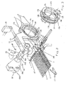
Figur 1- die aus zwei Rotations-Kantendrehern bestehende Vorrichtung wobei jeder Rotations-Kantendreher einen separaten Fremdantrieb besitzt,
Figur 2- die aus zwei Rotations-Kantendrehern bestehende Vorrichtung, wobei jeder Rotations-Kantendreher einen separaten integralen Antrieb besitzt und wobei die Vorrichtung von einer Trageinrichtung aufgenommen ist,
Figur 3- die als Ring ausgebildeten Dreherscheiben der Rotations-Kantendreher gemäß
Figur 2, mit drehwinkelversetzten Fadenführungsösen, Figur 4- die aus zwei Rotations-Kantendrehern bestehende Vorrichtung, wobei der eine Kantendreher einen Fremdantrieb und der andere Kantendrehern einen integralen Antrieb besitzt,
Figur 5- die aus zwei Rotations-Kantendrehern bestehende Vorrichtung gemäß Figur 5, wobei die Rotationskörper der Kantendreher die Drehrichtungsumkehr unabhängig voneinander ausführen,
Figur 6- die eintragsseitige Fangleiste,
Figur 7- die eintragsseitige Gewebeleiste mit Bindungsaussetzern.
- FIG. 1
- the device consisting of two rotary edgers with each rotary edger having a separate external drive,
- FIG. 2
- the device consisting of two rotary edgers, each rotary edger having a separate integral drive and the device being received by a support,
- FIG. 3
- the trained as a ring leno wheels of the rotary edge cutter according to Figure 2, with rotational angle offset yarn guide eyelets,
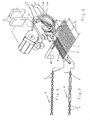
- FIG. 4
- the device consisting of two rotary editors, one edge-driver having an external drive and the other edge-turning device having an integral drive,
- FIG. 5
- the device consisting of two rotary edgebanders according to FIG. 5, wherein the rotational bodies of the edge drivers execute the direction of rotation reversal independently of one another,
- FIG. 6
- the entry-side fishing line,
- FIG. 7
- the entry-side fabric strip with binding misfires.
Gemäß Figur 1 besteht die Vorrichtung aus einem ersten Rotations-Kantendreher 12 und aus einem zweiten Rotations-Kantendrehers 13. Der Aufbau, die Anordnung und die Wirkungsweise beider Kantendreher ist in der DE 44 05 777 C1 umfassend beschrieben, so dass an dieser Stelle auf Wiederholungen verzichtet wird.According to FIG. 1, the device consists of a first
Jeder der Kantendreher 12, 13 besitzt einen Dreherfäden 7 bzw. einen Fangleistenfäden 9 führenden Rotationskörper 12a mit hier nicht sichtbaren Fadensführungsösen 12b und einen Rotationskörper 13a mit Fangleistenfäden führenden Fadenführungsösen 13b.Each of the
Beide Kantendreher 12, 13 stehen mit je einem Drehantrieb 14 drehantreibbar in Verbindung. Die Drehantriebe 14 werden von einer Antriebssteuerung 15 angesteuert.Both
Durch jeweils eine Halbdrehung des Rotationskörpers 12a, 13a, um die Mittenachse 25 bildet der Rotationskörper 12a mit den Dreherfäden 7 ein Gewebeleistenfach 8 und der Rotationskörper 13a ein Fangleistenfach 10 etwa synchron zur Bildung des Webfaches 6 mit den Kettfäden 5 aus.By one half turn of the
Die Mittel zur Bildung des Webfaches 6 sind hier nicht dargestellt, weil allgemein bekannt.The means for forming the
In die geöffneten Fächer 6, 8, 10 wird wenigstens ein Schussfaden 4 von der Eintragsseite des Webfaches 6 zur Ankunfts- oder Auszugsseite mittels pneumatischen oder mechanischen Eintragsorganen eingetragen.In the
Der hier in die Fächer 6, 8, 10 eingetragene Schussfaden 4 wird bis zum Anschlagen durch das Webblatt 27 an die Anschlagkante 1a,2a des Gewebes 1 bzw. der Gewebeleiste 2 und durch das Hilfswebblatt 28 an die Anschlagkante 3a der Fangleiste 3 und bis zum Abbinden durch die Fachbildeorgane auszugsseitig des Webfaches 6 von dem Schussfadeneintragsorgan 26 gehalten.The here in the
Nach dem Abbinden des Schussfadens 4 wird mittels synchroner Steuerung durch die Webfachbildeorgane erneut ein Webfach 6 und durch jeweils eine Halbdrehung der Rotationskörper 12a, 13a erneut ein Gewebeleisten- und Fangleistenfach 8, 10 gebildet, in die erneut wenigstens ein Schussfaden eingetragen wird. Dadurch entsteht ein Gewebe 1 mit einer Gewebeleiste 2 und beabstandet dazu eine zeitweilig vorhandene Fangleiste 3.After setting of the
Bei der Herstellung der Gewebeleiste 2 und der Fangleiste 3 ist es erfindungswesentlich, dass die Rotationskörper 12a, 13a durch eine Vielzahl von aufeinander folgenden Halbdrehungen z.B. in die eine Drehrichtung und vorzugsweise durch die gleiche Vielzahl von aufeinander folgenden Halbdrehungen in die andere Drehrichtung sowohl die Gewebeleiste 2 als auch die Fangleisten 3 als eine feste Volldreherkante ausbilden.In the manufacture of the
Bei der hier dargestellten Vorrichtung handelt es sich um rechtsseitig in der Webmaschine angeordnete Rotations-Kantendreher 12 und 13; eine weitere Vorrichtung gleichen Aufbaus ist linksseitig in der Webmaschine eingeordnet, wie z.B. die Figuren 4 und 5 zeigen.The device shown here is arranged on the right side in the loom
Um die freien Enden der Schussfäden 4 in der Fangleiste geordnet einer hier nicht dargestellten Gewebebreithaltevorrichtung zuführen zu können, ist zu beiden Seiten des Gewebes 1 wenigstens eine Halte- oder Streckvorrichtung 29, 30 (vgl. Figuren 4 und 5) vorgesehen.In order to be able to supply the free ends of the
Durch die koaxiale Anordnung der beiden Rotations-Kantendreher 12, 13 wird zwischen der Gewebeleiste 2 und der Fangleiste 3 eine Gewebe- oder Schneidgasse 16 gebildet, siehe auch Figur 4, in die eine Trenneinrichtung 17 eingreift und die Fangleiste zu gegebener Zeit von dem Gewebe 1 abtrennt.Due to the coaxial arrangement of the two
Da jeder Rotations-Kantendreher 12,13 der Vorrichtung mit einem eigenen Drehantrieb 14 ausgerüstet ist, wird es möglich, jeden Rotations-Kantendreher 12, 13 individuell, insbesondere im Hinblick auf die Umkehrung der Drehrichtung und auf den Zeitpunkt zum Abbinden der Schussfäden 4 zur Bildung der auszugseitigen Fangleiste 3, zu steuern.Since each
Die Fangleistenfäden 9 für die Fangleiste 3 werden, wie die Dreherfäden 7 für die Gewebeleiste 2, von auf Haltern 19 bzw. 18 angeordneten Spulen 21 bzw. 20 abgezogen, wobei die Halter 18,19 ortsfest gelagert sind.The
In dem Fall, dass eine Drehrichtungsumkehr der Rotationskörper 12a, 13a nicht vorgesehen ist, sind die Spulen 20, 21 auf einem nicht dargestellten, drehangetriebenen Spulenhalter angeordnet. Ein solcher drehangetriebener Spulenhalter ist erforderlich, um erstens keine gegenseitigen Umschlingungen der Dreherfäden 7 und zweitens keine gegenseitigen Umschlingungen der Fangleistenfäden 9 auf dem Weg zwischen den Rotationskörpern 12a, 13a und den Spulen 20, 21 entstehen zu lassen.In the event that a reversal of rotation of the
In Figur 2 besteht die Vorrichtung aus einem ersten Rotations-Kantendreher 12 und einem zweiten Rotations-Kantendreher 13. Aufbau, Anordnung und Wirkungsweise beider Kantendreher sind in der DE 44 05 776 C1 offenbart. Wesentlich ist hier, dass beide Rotationskörper 12a, 13a die Rotoren eines elektromotorischen Stellantriebes sind. Beide Kantendreher bilden auch hier eine strukturelle Einheit, die von einer Trageinrichtung 22 aufgenommen ist.In FIG. 2, the device consists of a first
Das Bilden des Gewebeleisten- und Fangleistenfaches 8, 10 erfolgt analog der Funktionsweise der Vorrichtung gemäß Figur 1. Über die Antriebssteuerung 15 ist jeder Kantendreher 12,13 individuell ansteuer- und betreibbar im Einklang mit der Webfachbildung.The formation of the Gewebeleisten- and
Die Trageinrichtung 22 als Ganzes ist über die Langlöcher 22d durch entsprechende Maschinenelemente mit der Webmaschine verbindbar und in Richtung des Doppelpfeils 32 positionierbar. Mit dem ersten Bauteil 22a ist wenigstens ein zweites und drittes Bauteil 22b, 22c verbunden. Das dritte Bauteil 22c ist in einer Ebene allein in Richtung des Doppelpfeils 33 um eine Vertikalachse 23 schwenkbar angeordnet. Die zu einer strukturellen Einheit kombinierten Rotations-Kantendreher 12, 13 sind dabei mit dem dritten Bauteil 22c derart verbunden, dass die Einheit längs der Mittenachse 24 des Bauteils 22c verschiebbar und um diese Mittenachse 24 schwenkbar ist.The
Bei überbreit gebäumten Webketten ist die Schwenkbarkeit der strukturellen Einheit von besonderem Vorteil. Die Dreherfäden 7 und die Fangleistenfäden 9 werden auch hier von Spulen 20, 21 abgezogen, wie bereits in Figur 1 dargestellt.With webbings folded over, the pivotability of the structural unit is of particular advantage. The
Figur 3 zeigt zwei um die Mittenachse 25 rotierbare Rotationskörper 12a,13a mit Fadenführungsösen 12b, 13b. Die Rotationskörper 12a, 13a sind entsprechend der Vorrichtung gemäß Figur 1 oder 2 ausgebildet.FIG. 3 shows two
Im Hinblick auf den Zeitpunkt der Abbindung der Schussfäden in der Fangleiste 3 ist es erfindungswesentlich, dass das Fangleistenfach 10 den Schussfaden 4 um einige Drehwinkelgrade Δα vor dem Gewebeleistenfach 8 abbindet. Anders ausgedrückt, die Rotation des Rotationskörpers 13b eilt der Rotation des Rotationskörpers 12b sowohl im Vorlauf gemäß Pfeil 34 als auch nach Richtungsumkehr im Rücklauf gemäß Pfeil 35 voraus. Das Maß der vorauseilenden Rotation, d.h. der Betrag Δα, ist in der Antriebssteuerung 15 frei programmierbar.With regard to the timing of the setting of the weft threads in the
Figur 4 zeigt eine eintragsseitig des Webfaches 6 angeordnete Vorrichtung mit unterschiedlichen Drehantrieben. Während zum Bilden der Gewebeleiste 2 ein erster Rotations-Kantendreher 12 mit integralem Drehantrieb vorgesehen ist, also der Rotationskörper 12a der Rotor eines elektromotorischen Stellantriebes ist, wird die Fangleiste 3 mittels eines fremd angetriebenen Rotationskörpers 13a gebildet (Drehantrieb 14).Figure 4 shows an entry side of the
Die Antriebe der beiden Kantendreher 12, 13 werden von einer Antriebssteuerung 15 angesteuert. Eintragsseitig des Webfaches 6 sind, analog zur Ankunfts- bzw. Auszugsseite des Webfaches 6, die Enden der abgebundenen Schussfäden 4 von einer Halte- oder Streckvorrichtung 30 bis zum Einlauf in eine nicht dargestellte Breithalteeinrichtung vorzugsweise pneumatisch gestreckt gehalten.The drives of the two
Figur 5 zeigt eine Vorrichtung, wie sie bereits in Figur 4 dargestellt ist. Gemäß dem erfindungsgemäßen Verfahren zum Bilden einer Gewebeleiste 2 und einer Fangleiste 3 ist hier das Verhältnis von Anzahl der Drehrichtungsumkehrungen der Rotationskörper 12a, 13a je Gewebeabschnitt 31 verschieden von eins, d.h. nicht nach jedem Schussfadeneintrag erfolgt eine Umkehr der Drehrichtung der Rotationskörper 12a, 13a.FIG. 5 shows a device as already shown in FIG. Here, according to the method of forming a
Zur Herstellung einer qualitativ hochwertigen Gewebeleiste 2 an Geweben 1 für die Bekleidungsindustrie ist es zum Beispiel von Vorteil, wenn die Umsteuerung der Drehrichtung des Rotationskörpers 12a für die Gewebeleiste 2 nach der Herstellung von mehr als 20 Volldreherabbindungen erfolgt, während die Drehrichtung des Rotationskörpers 13a zur Herstellung der Fangleiste 3 nach weniger als zehn Volldreherabbindungen erfolgt. Dadurch wird erreicht, dass die Gewebeleiste visuell schön ausgebildet ist und die Fangleiste 3 eine vergleichsweise höhere Schussdichte aufweisen kann, als sie mit jedem anderen bekannten Drehersystem erreichbar ist.To produce a high-
Erfindungswesentlich ist also, dass je Gewebeabschnitt 31 oder Schussfolge das Verhältnis der Drehrichtungsumkehrungen einer aus zwei Rotations-Kantendrehern 12, 13 bestehenden Vorrichtung zur Bildung einer Gewebeleiste 2 und einer Fangleiste 3 beliebig variierbar ist und dass diese Variation frei programmiert werden kann.It is therefore essential to the invention that the ratio of the reversals of rotation of a device consisting of two
Figur 6 zeigt Fangleistenfäden 9, die durch Rotation des Rotationskörpers 13a in eine Richtung die Enden der Schussfäden 4 mittels Volldreherabbindungen zu einer Fangleiste 3 ausbilden. In der Fangleiste 3 wie auch in der Gewebeleiste 2 ist der Punkt der Drehrichtungsumkehr visuell nicht erkennbar. Im vorliegenden Beispiel ist also nicht dargestellt, dass eine Drehrichtungsumkehr des Rotationskörpers 13a ausgeführt wurde.Figure 6 shows
Figur 7 zeigt die Dreherfäden 7, die mittels Rotation des Rotationskörpers 12a in einer Richtung die Enden der Schussfäden 4 mittels Volldreherabbindungen zu einer Gewebeleiste 2 ausbilden. Aufgrund der freien Programmierung der Rotations-Kantendreher 12, 13 sind Abbindungsvarianten für die Schussfäden 4 denkbar, wie z.B. sogenannte Bindungsaussetzer, die gleichermaßen in der Gewebeleiste 2 und in der Fangleiste 3 realisierbar sind.FIG. 7 shows the
Zusammenfassend kann festgestellt werden, dass die an sich bekannte Technologie zur Herstellung einer Volldreher-Gewebeleiste 2 ohne Einschränkungen zur Herstellung einer zeitweilig vorhandenen Fangleiste 3 einsetzbar ist. Es kann ferner festgestellt werden, dass durch die Kombination von zwei Rotations-Kantendrehern 12, 13 zu einer strukturellen Einheit und unter Anwendung der Volldreher-Technologie neben Materialeinsparungen zum Bilden der Fangleisten 3 Materialeinsparungen je Schussfaden 4 erreichbar sind. Die Einsparung an Schussmaterial wird dadurch möglich, dass insbesondere auf Greiferwebmaschinen die Fadenhinreicheaggregate und die Schussfadenschere 17 um die verminderte Breite einer konventionell hergestellten Fangleiste 3 näher zum Webblatt 27 hin positioniert werden können. Ferner ist es dadurch möglich, die Startposition der Schussfadeneintragsorgane (Bringer- und Nehmergreifer) näher zum Webblatt 27 hin einzustellen.In summary, it can be stated that the technology known per se for producing a full-
- 11
- Gewebetissue
- 1 a1 a
- Anschlagkante des GewebesStop edge of the fabric
- 22
- GewebeleisteGewebeleiste
- 2a2a
- Anschlagkante der GewebeleisteStop edge of the fabric strip
- 33
- Fangleistestop profile
- 3a3a
- Anschlagkantestop edge
- 44
- Schussfadenweft
- 55
- Kettfadenwarp
- 66
- Webfachshed
- 77
- Dreherfadenleno thread
- 88th
- GewebeleistenfachFabric selvedge shed
- 99
- FangleistenfadenCatch selvedge thread
- 1010
- FangleistenfachCatch selvedge shed
- 1212
- erster Rotations-Kantendreherfirst rotary edge cutter
- 12a12a
- Rotationskörperbody of revolution
- 12b12b
- Fadenführungsösethread guiding eye
- 1313
- zweiter Rotations-Kantendrehersecond rotary edge cutter
- 13a13a
- Rotationskörperbody of revolution
- 13b13b
- Fadenführungsösethread guiding eye
- 1414
- Drehantriebrotary drive
- 1515
- Antriebssteuerungdrive control
- 1616
- Gewebe- oder SchneidgasseTissue or cutting alley
- 1717
- Trenneinrichtung (Schussfadenschere)Separating device (weft scissors)
- 1818
- Halterholder
- 1919
- Halterholder
- 2020
- SpuleKitchen sink
- 2121
- SpuleKitchen sink
- 2222
- Trageinrichtungsupport means
- 22a22a
- erstes Bauteilfirst component
- 22b22b
- zweites Bauteilsecond component
- 22c22c
- drittes Bauteilthird component
- 22d22d
- LanglochLong hole
- 2323
- Vertikalachsevertical axis
- 2424
- Mittenachsemid-axis
- 2525
- gemeinsame Mittenachsecommon center axis
- 2626
- SchussfadeneintragsorganWeft insertion member
- 2727
- Webblattreed
- 2828
- HilfswebblattHilfswebblatt
- 2929
- Halte- oder StreckvorrichtungHolding or stretching device
- 3030
- Halte- oder StreckvorrichtungHolding or stretching device
- 3131
- Gewebeabschnittfabric section
- 3232
- Doppelpfeildouble arrow
- 3333
- Doppelpfeildouble arrow
- 3434
- Pfeilarrow
- 3535
- Pfeilarrow
- ΔαΔα
- Drehwinkelangle of rotation
Claims (13)
- Method for the production on looms of a fabric (1) having fabric selvedges (2) and at least one temporarily present catch selvedge (3), according to which at least one weft thread (4) is introduced into a shed (6) formed from warp threads (5), into a fabric selvedge shed (8) formed from leno threads (7) and into a catch selvedge shed (10) formed from catch selvedge threads (9), thereupon the weft thread (4) is beaten up to the fell (1a, 2a, 3a) of the fabric (1), the fabric selvedge (20) and the catch selvedge (3), is subsequently bound in by the warp threads (5), the leno threads (7) and the catch selvedge threads (9) and thereafter is cut by means of at least one weft thread cutting device (17) from a weft thread (4) held in readiness, wherein the fabric selvedge (2) and the catch selvedge (3) are each formed as a full-cross leno selvedge by means of rotation of a respective rotating body (12a, 13a) guiding the leno threads (7) and the catch selvedge threads (9) of a first and a second rotary leno mechanism (12, 13) having a controlled reversal of rotation direction,
characterised in that
the rotating bodies (12a, 13a) are driven and are controlled independently of the drive of the loom and in that the rotation and the reversal of the rotation direction of each rotating body (12a, 13a) is freely programmable, wherein on the weft thread exit side and arrival side respectively of the shed (6) an advance Δα of the rotating body (13a) guiding the catch selvedge threads (9) with respect to the rotating body (12a) guiding the leno threads (7) is freely programmable, whereby with an advance Δα of several angular degrees the catch selvedge shed (10) is closed ahead of the fabric selvedge shed (8) and this advance Δα is maintained when reversal of the rotation direction is effected. - Method for the production on looms of a fabric (1) having fabric selvedges (2) and at least one temporarily present catch selvedge (3), according to which at least one weft thread (4) is introduced into a shed (6) formed from warp threads (5), into a fabric selvedge shed (8) formed from leno threads (7) and into a catch selvedge shed (10) formed from catch selvedge threads (9), thereupon the weft thread (4) is beaten up to the fell (1a, 2a, 3a) of the fabric (1), the fabric selvedge (20) and the catch selvedge (3), is subsequently bound in by the warp threads (5), the leno threads (7) and the catch selvedge threads (9) and thereafter is cut by means of at least one weft thread cutting device (17) from a weft thread (4) held in readiness, wherein the fabric selvedge (2) and the catch selvedge (3) are each formed as a full-cross leno selvedge by means of rotation of a respective rotating body (12a, 13a) guiding the leno threads (7) and the catch selvedge threads (9) of a first and a second rotary leno mechanism (12, 13) with no reversal of the rotation direction, and wherein both the leno threads (7) and the catch selvedge threads (9) are drawn from spools arranged on a rotatably driven holder,
characterised in that
the rotating bodies (12a, 13a) are driven and are controlled independently of the drive of the loom and in that the rotation of each rotating body (12a, 13a) is freely programmable, wherein on the weft thread exit side and arrival side respectively of the shed (6) an advance Δα of the rotating body (13a) guiding the catch selvedge threads (9) with respect to the rotating body (12a) guiding the leno threads (7) is freely programmable, whereby with an advance Δα of several angular degrees the catch selvedge shed (10) is closed ahead of the fabric selvedge shed (8). - Apparatus for carrying out the method according to claim 1, comprising:a first rotary leno mechanism (12) having a rotating body (12a) guiding leno threads (7) to form a fabric selvedge (2),a second rotary leno mechanism (13) having a rotating body (13a) guiding catch selvedge threads (9) to form a catch selvedge (3),wherein the fabric and catch selvedges (2, 3) are producible by full-cross leno interlacings of the weft threads (4) by means of controlled reversal of the rotation direction of the rotating bodies (12, 13),characterised in thateach rotating body (12a, 13a) has a rotary drive (14), which is independent of the main drive of the loom, and in that both rotary drives (14) are controllable independently of one another, wherein on the weft thread exit side and arrival side respectively of the shed (6) an advance Δα of the rotating body (13a) guiding the catch selvedge threads (9) with respect to the rotating body (12a) guiding the leno threads (7) is freely programmable, whereby with an advance Δα of several angular degrees the catch selvedge shed (10) is closed ahead of the fabric selvedge shed (8) and this advance Δα is maintained when reversal of the rotation direction is effected.
- Apparatus for carrying out the method according to claim 2, comprising:a) a first rotary leno mechanism (12) having a rotating body (12a) guiding leno threads (7) to form a fabric selvedge (2),b) a second rotary leno mechanism (13) having a rotating body (13a) guiding catch selvedge threads (9) to form a catch selvedge (3),c) the fabric and catch selvedges (2, 3) are producible by full-cross leno interlacings of the weft threads (4) without reversal of the rotation direction of the rotating bodies (12a, 13a) andd) a holder rotatably driven with spools for the leno and catch selvedge threads,characterised in that
each rotating body (12a, 13a) has a rotary drive (14), which is independent of the main drive of the loom, and in that both rotary drives (14) are controllable independently of one another, wherein on the weft thread exit side and arrival side respectively of the shed (6) an advance Δα of the rotating body (13a) guiding the catch selvedge threads (9) with respect to the rotating body (12a) guiding the leno threads (7) is freely programmable, whereby with an advance Δα of several angular degrees the catch selvedge shed (10) is closed ahead of the fabric selvedge shed (8). - Apparatus according to one of claims 3 and 4, characterised in that the first and the second rotary leno mechanism (12, 13) together form a structural unit in the form of a modular construction system.
- Apparatus according to any one of claims 3 to 5, characterised in that each rotating body (12a, 13a) is in the form of a preferably annular leno disc and has thread guiding eyes (12b, 13b).
- Apparatus according to any one of claims 3 to 6, characterised in that at least one of the two rotating bodies (12a, 13a) is the rotor of an electromotive actuator.
- Apparatus according to claim 3, characterised in that per fabric section or weft sequence the number and the times of the reversal of rotation direction and the number of rotations of each rotating body (12a, 13a) are freely programmable by means of a drive control system (15).
- Apparatus according to claim 4, characterised in that per fabric section or weft sequence the number of rotations of each rotating body (12a, 13a) is freely programmable by means of a drive control system (15).
- Apparatus according to claim 5, characterised in that the structural unit formed by the rotary leno mechanisms (12, 13) is position-adjustable within the loom by means of a carrier arrangement (22).
- Apparatus according to claim 10, characterised by a carrier arrangement (2) having the following features:a) at least one first structural component (22a) fixedly arranged on the loom and adjustable in at least one plane,b) at least one second and third structural component (22b, 22c) connected to the first structural component (22a), the third structural component (22c) being arranged to be pivotable about a vertical axis (23) in a single plane and
whereinc) the structural unit is connected to the third structural component (22c) in such a way that the unit is slidable along and is pivotable about the centre line (24) of the third structural component. - Apparatus according to claim 11, characterised in that the first and the second rotary leno mechanisms (12, 13) of the structural unit are received by the third structural component (22c) in such a way that their rotating bodies (12a, 13a) rotate about a common centre line (25).
- Apparatus according to claims 12, characterised in that in an operative state of the structural unit, the centre line (25) lies approximately parallel to the fell (1a, 2a, 3a) of the fabric (1), the fabric selvedge and the catch selvedge (3).
Applications Claiming Priority (2)
| Application Number | Priority Date | Filing Date | Title |
|---|---|---|---|
| DE19720634A DE19720634C1 (en) | 1997-05-16 | 1997-05-16 | Method for forming a fabric and catch strip in the manufacture of a fabric on weaving machines and device for carrying out the method |
| DE19720634 | 1997-05-16 |
Publications (2)
| Publication Number | Publication Date |
|---|---|
| EP0878570A1 EP0878570A1 (en) | 1998-11-18 |
| EP0878570B1 true EP0878570B1 (en) | 2007-05-23 |
Family
ID=7829702
Family Applications (1)
| Application Number | Title | Priority Date | Filing Date |
|---|---|---|---|
| EP98107341A Revoked EP0878570B1 (en) | 1997-05-16 | 1998-04-22 | Method for forming a fabric with selvedges and at least one catch selvedge on looms and device for carrying out this method |
Country Status (12)
| Country | Link |
|---|---|
| US (1) | US5996647A (en) |
| EP (1) | EP0878570B1 (en) |
| JP (1) | JP2933915B2 (en) |
| KR (1) | KR100316869B1 (en) |
| CN (1) | CN1201038C (en) |
| AT (1) | ATE363002T1 (en) |
| BR (1) | BR9804911A (en) |
| CZ (1) | CZ294030B6 (en) |
| DE (2) | DE19720634C1 (en) |
| ID (1) | ID21959A (en) |
| TR (1) | TR199802677T1 (en) |
| WO (1) | WO1998053129A1 (en) |
Families Citing this family (24)
| Publication number | Priority date | Publication date | Assignee | Title |
|---|---|---|---|---|
| DE19716349C1 (en) * | 1997-04-18 | 1998-06-10 | Kloecker Entwicklungs Gmbh | Loom leno selvedge unit drive |
| ITMI991221A1 (en) * | 1999-05-31 | 1999-08-31 | Somet Soc Mec Tessile | DEVICE AND METHOD FOR THE FORMATION OF THE SELVEDGE IN A SEWING FRAME |
| KR20040053625A (en) * | 2002-12-17 | 2004-06-24 | 백경태 | Shed motion device of catch code yarn for shuttleless loom |
| DE10307489B3 (en) * | 2003-02-21 | 2004-11-11 | Lindauer Dornier Gesellschaft Mbh | Shed mechanism, for a loom, has drop wire and needle healds to give the warps structured movements to form a plain and a leno weave simultaneously within a weaving cycle |
| DE10313188A1 (en) * | 2003-03-25 | 2004-10-07 | Lindauer Dornier Gmbh | Rotary edge turning device of a weaving machine |
| DE10336006B4 (en) * | 2003-08-01 | 2007-07-12 | Lindauer Dornier Gesellschaft Mit Beschränkter Haftung | Device on a weaving machine for forming leno edges |
| DE102005022955A1 (en) * | 2005-05-19 | 2006-11-23 | Lindauer Dornier Gmbh | Method and device for holding a recorded after a starting operation of a loom, in particular air jet loom weft thread |
| DE102006025265A1 (en) | 2006-05-31 | 2007-12-06 | Lindauer Dornier Gmbh | Method and apparatus for forming a fabric edge on a rapier loom |
| JP2010111980A (en) * | 2008-11-10 | 2010-05-20 | Abedesignpro Co Ltd | Woven fabric product, and method for producing the same |
| EP2807299B1 (en) * | 2012-01-24 | 2025-10-22 | NIKE Innovate C.V. | Weaving finishing device |
| CN104126041B (en) | 2012-01-24 | 2017-10-10 | 耐克创新有限合伙公司 | multi-layer braid |
| CN104114473B (en) * | 2012-01-24 | 2017-03-15 | 耐克创新有限合伙公司 | Intermittent Braid Splicer |
| DE102012009420A1 (en) | 2012-05-11 | 2013-11-14 | Gebrüder Klöcker GmbH | Device for producing a fabric |
| JP6071391B2 (en) * | 2012-06-13 | 2017-02-01 | 津田駒工業株式会社 | Loom ear forming device |
| JP5671102B2 (en) * | 2013-06-27 | 2015-02-18 | アベデザインプロ株式会社 | Manufacturing method of textile products |
| CN103334209B (en) * | 2013-07-19 | 2015-10-28 | 安徽丹凤集团桐城玻璃纤维有限公司 | Band helps the glass fibre air-jet loom of yarn feeding device |
| JP6256350B2 (en) * | 2013-09-17 | 2018-01-10 | 東レ株式会社 | Loom and woven fabric manufacturing method |
| GB2571563B (en) * | 2018-03-01 | 2023-01-04 | Dewhurst James Ltd | Woven textile and associated method of manufacture |
| CN108330588A (en) * | 2018-03-05 | 2018-07-27 | 浙江理工大学 | The method for reinforcing weaving edge grinding using low melt point polyester fiber thermo-fuse |
| CN109402829A (en) * | 2018-11-12 | 2019-03-01 | 山东日发纺织机械有限公司 | Electric twisted edge mechanism |
| IT201900014982A1 (en) * | 2019-08-23 | 2021-02-23 | Santex Rimar Group S R L | DEVICE FOR WEFT SAVING IN WEAVING MACHINES |
| CN111304822B (en) * | 2020-03-24 | 2024-04-19 | 江苏百宏复合材料科技股份有限公司 | Double-ruffled-edge night light mosquito-repellent elastic belt and manufacturing method thereof |
| JP7518035B2 (en) * | 2021-05-10 | 2024-07-17 | 津田駒工業株式会社 | Loom selvedge yarn shedding device |
| CN116288853B (en) * | 2022-09-08 | 2025-07-15 | 山东金号家纺集团有限公司 | Twisted edge braiding device for preventing inner edge of towel from falling off |
Family Cites Families (12)
| Publication number | Priority date | Publication date | Assignee | Title |
|---|---|---|---|---|
| DE836475C (en) * | 1947-03-08 | 1952-04-15 | Sulzer Ag | Method and apparatus for binding edges on fabrics |
| BE757324A (en) * | 1969-10-09 | 1971-04-09 | Interbrev Sa | PROCESS FOR MANUFACTURING A RIBBON WITH SLIDING BUCKLES, NEEDLE TRADE IMPLEMENTING THIS PROCESS AND RIBBON OBTAINED BY THIS PROCESS, IN PARTICULAR TAPE FOR ZIPPER CLOSURE |
| US3952778A (en) * | 1975-04-28 | 1976-04-27 | Rockwell International Corporation | Selvage forming device |
| CH621158A5 (en) * | 1977-05-13 | 1981-01-15 | Rueti Ag Maschf | |
| US4421141A (en) * | 1979-08-06 | 1983-12-20 | Leesona Corporation | Fabric selvage forming |
| ATE3069T1 (en) * | 1979-08-16 | 1983-04-15 | Gebrueder Sulzer Aktiengesellschaft | LOOKING THREAD FEED DEVICE FOR A LOOPPING MACHINE. |
| JPS5771459A (en) * | 1980-10-15 | 1982-05-04 | Toyoda Automatic Loom Works | Abnormality detecting apparatus of ear yarn in ear molding apparatus of loom |
| IT1255133B (en) * | 1992-05-05 | 1995-10-20 | Luciano Corain | IMPROVEMENT IN A TEXTILE FRAME WITHOUT SHUTTLE |
| US5392819A (en) * | 1993-12-10 | 1995-02-28 | Hunshin Enterprise Co., Ltd. | Planetary gear type selvage forming and cord catching device for loom |
| DE59502454D1 (en) * | 1994-02-23 | 1998-07-16 | Dornier Gmbh Lindauer | Rotary edge turner for weaving machines |
| DE4405777C2 (en) * | 1994-02-23 | 2002-03-07 | Dornier Gmbh Lindauer | Rotary edger of a weaving machine |
| DE4405776C1 (en) * | 1994-02-23 | 1995-08-17 | Dornier Gmbh Lindauer | Rotary edger of a weaving machine |
-
1997
- 1997-05-16 DE DE19720634A patent/DE19720634C1/en not_active Revoked
-
1998
- 1998-04-22 DE DE59814010T patent/DE59814010D1/en not_active Revoked
- 1998-04-22 EP EP98107341A patent/EP0878570B1/en not_active Revoked
- 1998-04-22 AT AT98107341T patent/ATE363002T1/en not_active IP Right Cessation
- 1998-04-29 KR KR1019997000432A patent/KR100316869B1/en not_active Expired - Fee Related
- 1998-04-29 BR BR9804911-9A patent/BR9804911A/en not_active IP Right Cessation
- 1998-04-29 ID IDW990028D patent/ID21959A/en unknown
- 1998-04-29 TR TR1998/02677T patent/TR199802677T1/en unknown
- 1998-04-29 CN CNB988009722A patent/CN1201038C/en not_active Expired - Fee Related
- 1998-04-29 WO PCT/DE1998/001185 patent/WO1998053129A1/en not_active Ceased
- 1998-04-29 CZ CZ1999122A patent/CZ294030B6/en not_active IP Right Cessation
- 1998-05-08 JP JP10125887A patent/JP2933915B2/en not_active Expired - Fee Related
- 1998-05-13 US US09/078,338 patent/US5996647A/en not_active Expired - Fee Related
Also Published As
| Publication number | Publication date |
|---|---|
| TR199802677T1 (en) | 1999-07-21 |
| JP2933915B2 (en) | 1999-08-16 |
| WO1998053129A1 (en) | 1998-11-26 |
| JPH10325045A (en) | 1998-12-08 |
| BR9804911A (en) | 2000-01-25 |
| KR100316869B1 (en) | 2001-12-24 |
| KR20000023847A (en) | 2000-04-25 |
| CN1201038C (en) | 2005-05-11 |
| ID21959A (en) | 1999-08-19 |
| CN1234841A (en) | 1999-11-10 |
| US5996647A (en) | 1999-12-07 |
| DE59814010D1 (en) | 2007-07-05 |
| ATE363002T1 (en) | 2007-06-15 |
| CZ294030B6 (en) | 2004-09-15 |
| EP0878570A1 (en) | 1998-11-18 |
| DE19720634C1 (en) | 1998-10-01 |
| CZ12299A3 (en) | 1999-06-16 |
Similar Documents
| Publication | Publication Date | Title |
|---|---|---|
| EP0878570B1 (en) | Method for forming a fabric with selvedges and at least one catch selvedge on looms and device for carrying out this method | |
| EP0043441B2 (en) | Process and apparatus for making a woven seam between two ends of a fabric | |
| EP2004889B1 (en) | Webbing, method and ribbon needle loom for producing the same | |
| EP0674031B1 (en) | Rotary leno selvedge mechanism for looms | |
| EP1395692B1 (en) | Loom for the production of a gauze material | |
| WO1997024479A1 (en) | Device for producing a leno selvedge, in particular for shuttleless looms | |
| DE2845299A1 (en) | CONTACTORLESS WEB MACHINE | |
| EP0875610B1 (en) | Leno selvedge forming device, particularly for looms | |
| EP0674032B2 (en) | Rotary leno selvedge mechanism for looms | |
| EP1272699B1 (en) | Method for adjusting the weaving parameters of weaving machines, and control device | |
| DE29708758U1 (en) | Weaving machine | |
| EP0918103B1 (en) | Method and device for obtaining pure weft waste of catch selvedges | |
| EP2662479B1 (en) | Weaving machine with leno devices | |
| DE2164948A1 (en) | Loom having double shed - in which two wefts are inserted to form two joined pile fabrics | |
| EP0681044A1 (en) | Process and device to draw-off waste selvedge | |
| EP0973965A1 (en) | Weaving loom with pneumatic weft thread insertion | |
| DE10336006B4 (en) | Device on a weaving machine for forming leno edges | |
| EP1899516B1 (en) | Method and device for maintaining a weft thread which is introduced into a weaving machine, in particular an air-jet weaving machine, after the starting process | |
| DE3105965A1 (en) | WEAVING MACHINE | |
| DE1941404B2 (en) | Threading in and threading out device of a rapier shuttle loom | |
| EP0350574B1 (en) | Seaming machine for producing a seam for making a textile web endless. | |
| DE19743612C2 (en) | Method and device for producing sorted weft thread waste from catch strips | |
| WO2009030196A1 (en) | Method and device for eliminating weft threads having thread irregularities from woven fabrics | |
| WO2001059192A1 (en) | Method for deflecting a warp thread sheet during weaving and a weaving machine | |
| DE2935558C2 (en) | Method and device for working on shuttleless looms. |
Legal Events
| Date | Code | Title | Description |
|---|---|---|---|
| PUAI | Public reference made under article 153(3) epc to a published international application that has entered the european phase |
Free format text: ORIGINAL CODE: 0009012 |
|
| AK | Designated contracting states |
Kind code of ref document: A1 Designated state(s): AT BE CH DE ES FR GB IE IT LI NL PT SE |
|
| AX | Request for extension of the european patent |
Free format text: AL;LT;LV;MK;RO;SI |
|
| 17P | Request for examination filed |
Effective date: 19990113 |
|
| AKX | Designation fees paid |
Free format text: BE CH DE FR GB IT LI |
|
| RBV | Designated contracting states (corrected) |
Designated state(s): AT BE CH DE ES FR GB IE IT LI NL PT SE |
|
| 17Q | First examination report despatched |
Effective date: 20010928 |
|
| 17Q | First examination report despatched |
Effective date: 20010928 |
|
| GRAP | Despatch of communication of intention to grant a patent |
Free format text: ORIGINAL CODE: EPIDOSNIGR1 |
|
| RTI1 | Title (correction) |
Free format text: METHOD FOR FORMING A FABRIC WITH SELVEDGES AND AT LEAST ONE CATCH SELVEDGE ON LOOMS AND DEVICE FOR CARRYING OUT THIS METHOD |
|
| GRAS | Grant fee paid |
Free format text: ORIGINAL CODE: EPIDOSNIGR3 |
|
| GRAA | (expected) grant |
Free format text: ORIGINAL CODE: 0009210 |
|
| AK | Designated contracting states |
Kind code of ref document: B1 Designated state(s): AT BE CH DE ES FR GB IE IT LI NL PT SE |
|
| REG | Reference to a national code |
Ref country code: GB Ref legal event code: FG4D Free format text: NOT ENGLISH |
|
| REG | Reference to a national code |
Ref country code: CH Ref legal event code: EP |
|
| REG | Reference to a national code |
Ref country code: IE Ref legal event code: FG4D Free format text: LANGUAGE OF EP DOCUMENT: GERMAN |
|
| REF | Corresponds to: |
Ref document number: 59814010 Country of ref document: DE Date of ref document: 20070705 Kind code of ref document: P |
|
| REG | Reference to a national code |
Ref country code: CH Ref legal event code: NV Representative=s name: R. A. EGLI & CO. PATENTANWAELTE |
|
| PG25 | Lapsed in a contracting state [announced via postgrant information from national office to epo] |
Ref country code: SE Free format text: LAPSE BECAUSE OF FAILURE TO SUBMIT A TRANSLATION OF THE DESCRIPTION OR TO PAY THE FEE WITHIN THE PRESCRIBED TIME-LIMIT Effective date: 20070823 |
|
| PG25 | Lapsed in a contracting state [announced via postgrant information from national office to epo] |
Ref country code: ES Free format text: LAPSE BECAUSE OF FAILURE TO SUBMIT A TRANSLATION OF THE DESCRIPTION OR TO PAY THE FEE WITHIN THE PRESCRIBED TIME-LIMIT Effective date: 20070903 |
|
| GBT | Gb: translation of ep patent filed (gb section 77(6)(a)/1977) |
Effective date: 20070926 |
|
| NLV1 | Nl: lapsed or annulled due to failure to fulfill the requirements of art. 29p and 29m of the patents act | ||
| ET | Fr: translation filed | ||
| REG | Reference to a national code |
Ref country code: IE Ref legal event code: FD4D |
|
| PG25 | Lapsed in a contracting state [announced via postgrant information from national office to epo] |
Ref country code: PT Free format text: LAPSE BECAUSE OF FAILURE TO SUBMIT A TRANSLATION OF THE DESCRIPTION OR TO PAY THE FEE WITHIN THE PRESCRIBED TIME-LIMIT Effective date: 20071023 Ref country code: NL Free format text: LAPSE BECAUSE OF FAILURE TO SUBMIT A TRANSLATION OF THE DESCRIPTION OR TO PAY THE FEE WITHIN THE PRESCRIBED TIME-LIMIT Effective date: 20070523 Ref country code: IE Free format text: LAPSE BECAUSE OF FAILURE TO SUBMIT A TRANSLATION OF THE DESCRIPTION OR TO PAY THE FEE WITHIN THE PRESCRIBED TIME-LIMIT Effective date: 20070523 |
|
| PLBI | Opposition filed |
Free format text: ORIGINAL CODE: 0009260 |
|
| PLBI | Opposition filed |
Free format text: ORIGINAL CODE: 0009260 |
|
| 26 | Opposition filed |
Opponent name: GEBRUEDER KLOECKER GMBH Effective date: 20080215 |
|
| PLAX | Notice of opposition and request to file observation + time limit sent |
Free format text: ORIGINAL CODE: EPIDOSNOBS2 |
|
| 26 | Opposition filed |
Opponent name: GEBRUEDER KLOECKER GMBH Effective date: 20080215 Opponent name: PICANOL N.V. Effective date: 20080221 |
|
| RDAF | Communication despatched that patent is revoked |
Free format text: ORIGINAL CODE: EPIDOSNREV1 |
|
| PGFP | Annual fee paid to national office [announced via postgrant information from national office to epo] |
Ref country code: DE Payment date: 20080313 Year of fee payment: 11 |
|
| PLAB | Opposition data, opponent's data or that of the opponent's representative modified |
Free format text: ORIGINAL CODE: 0009299OPPO |
|
| PLBB | Reply of patent proprietor to notice(s) of opposition received |
Free format text: ORIGINAL CODE: EPIDOSNOBS3 |
|
| PGFP | Annual fee paid to national office [announced via postgrant information from national office to epo] |
Ref country code: IT Payment date: 20080415 Year of fee payment: 11 Ref country code: BE Payment date: 20080403 Year of fee payment: 11 |
|
| RDAG | Patent revoked |
Free format text: ORIGINAL CODE: 0009271 |
|
| STAA | Information on the status of an ep patent application or granted ep patent |
Free format text: STATUS: PATENT REVOKED |
|
| PGFP | Annual fee paid to national office [announced via postgrant information from national office to epo] |
Ref country code: CH Payment date: 20080725 Year of fee payment: 11 |
|
| REG | Reference to a national code |
Ref country code: CH Ref legal event code: PL |
|
| 27W | Patent revoked |
Effective date: 20080714 |
|
| GBPR | Gb: patent revoked under art. 102 of the ep convention designating the uk as contracting state |
Effective date: 20080714 |
|
| PGFP | Annual fee paid to national office [announced via postgrant information from national office to epo] |
Ref country code: FR Payment date: 20080317 Year of fee payment: 11 |
|
| PGFP | Annual fee paid to national office [announced via postgrant information from national office to epo] |
Ref country code: GB Payment date: 20080408 Year of fee payment: 11 |