EP0764842A2 - Schaltung zum Detektion von Frequenzabweichungen und dieselbe benutzendes Messgerät - Google Patents
Schaltung zum Detektion von Frequenzabweichungen und dieselbe benutzendes Messgerät Download PDFInfo
- Publication number
- EP0764842A2 EP0764842A2 EP96306784A EP96306784A EP0764842A2 EP 0764842 A2 EP0764842 A2 EP 0764842A2 EP 96306784 A EP96306784 A EP 96306784A EP 96306784 A EP96306784 A EP 96306784A EP 0764842 A2 EP0764842 A2 EP 0764842A2
- Authority
- EP
- European Patent Office
- Prior art keywords
- oscillator
- circuit
- gain
- measuring apparatus
- hardness
- Prior art date
- Legal status (The legal status is an assumption and is not a legal conclusion. Google has not performed a legal analysis and makes no representation as to the accuracy of the status listed.)
- Granted
Links
Images


Classifications
-
- G—PHYSICS
- G01—MEASURING; TESTING
- G01P—MEASURING LINEAR OR ANGULAR SPEED, ACCELERATION, DECELERATION, OR SHOCK; INDICATING PRESENCE, ABSENCE, OR DIRECTION, OF MOVEMENT
- G01P15/00—Measuring acceleration; Measuring deceleration; Measuring shock, i.e. sudden change of acceleration
- G01P15/02—Measuring acceleration; Measuring deceleration; Measuring shock, i.e. sudden change of acceleration by making use of inertia forces using solid seismic masses
- G01P15/08—Measuring acceleration; Measuring deceleration; Measuring shock, i.e. sudden change of acceleration by making use of inertia forces using solid seismic masses with conversion into electric or magnetic values
- G01P15/097—Measuring acceleration; Measuring deceleration; Measuring shock, i.e. sudden change of acceleration by making use of inertia forces using solid seismic masses with conversion into electric or magnetic values by vibratory elements
-
- G—PHYSICS
- G01—MEASURING; TESTING
- G01N—INVESTIGATING OR ANALYSING MATERIALS BY DETERMINING THEIR CHEMICAL OR PHYSICAL PROPERTIES
- G01N3/00—Investigating strength properties of solid materials by application of mechanical stress
- G01N3/40—Investigating hardness or rebound hardness
-
- A—HUMAN NECESSITIES
- A61—MEDICAL OR VETERINARY SCIENCE; HYGIENE
- A61B—DIAGNOSIS; SURGERY; IDENTIFICATION
- A61B5/00—Measuring for diagnostic purposes; Identification of persons
- A61B5/0048—Detecting, measuring or recording by applying mechanical forces or stimuli
- A61B5/0051—Detecting, measuring or recording by applying mechanical forces or stimuli by applying vibrations
-
- A—HUMAN NECESSITIES
- A61—MEDICAL OR VETERINARY SCIENCE; HYGIENE
- A61B—DIAGNOSIS; SURGERY; IDENTIFICATION
- A61B5/00—Measuring for diagnostic purposes; Identification of persons
- A61B5/02—Detecting, measuring or recording pulse, heart rate, blood pressure or blood flow; Combined pulse/heart-rate/blood pressure determination; Evaluating a cardiovascular condition not otherwise provided for, e.g. using combinations of techniques provided for in this group with electrocardiography or electroauscultation; Heart catheters for measuring blood pressure
- A61B5/02007—Evaluating blood vessel condition, e.g. elasticity, compliance
-
- A—HUMAN NECESSITIES
- A61—MEDICAL OR VETERINARY SCIENCE; HYGIENE
- A61B—DIAGNOSIS; SURGERY; IDENTIFICATION
- A61B5/00—Measuring for diagnostic purposes; Identification of persons
- A61B5/103—Detecting, measuring or recording devices for testing the shape, pattern, colour, size or movement of the body or parts thereof, for diagnostic purposes
-
- A—HUMAN NECESSITIES
- A61—MEDICAL OR VETERINARY SCIENCE; HYGIENE
- A61B—DIAGNOSIS; SURGERY; IDENTIFICATION
- A61B5/00—Measuring for diagnostic purposes; Identification of persons
- A61B5/68—Arrangements of detecting, measuring or recording means, e.g. sensors, in relation to patient
- A61B5/6801—Arrangements of detecting, measuring or recording means, e.g. sensors, in relation to patient specially adapted to be attached to or worn on the body surface
- A61B5/6843—Monitoring or controlling sensor contact pressure
-
- G—PHYSICS
- G01—MEASURING; TESTING
- G01H—MEASUREMENT OF MECHANICAL VIBRATIONS OR ULTRASONIC, SONIC OR INFRASONIC WAVES
- G01H13/00—Measuring resonant frequency
-
- G—PHYSICS
- G01—MEASURING; TESTING
- G01L—MEASURING FORCE, STRESS, TORQUE, WORK, MECHANICAL POWER, MECHANICAL EFFICIENCY, OR FLUID PRESSURE
- G01L9/00—Measuring steady of quasi-steady pressure of fluid or fluent solid material by electric or magnetic pressure-sensitive elements; Transmitting or indicating the displacement of mechanical pressure-sensitive elements, used to measure the steady or quasi-steady pressure of a fluid or fluent solid material, by electric or magnetic means
- G01L9/12—Measuring steady of quasi-steady pressure of fluid or fluent solid material by electric or magnetic pressure-sensitive elements; Transmitting or indicating the displacement of mechanical pressure-sensitive elements, used to measure the steady or quasi-steady pressure of a fluid or fluent solid material, by electric or magnetic means by making use of variations in capacitance, i.e. electric circuits therefor
-
- G—PHYSICS
- G01—MEASURING; TESTING
- G01N—INVESTIGATING OR ANALYSING MATERIALS BY DETERMINING THEIR CHEMICAL OR PHYSICAL PROPERTIES
- G01N3/00—Investigating strength properties of solid materials by application of mechanical stress
- G01N3/40—Investigating hardness or rebound hardness
- G01N3/405—Investigating hardness or rebound hardness by determining the vibration frequency of a sensing element in contact with the specimen
-
- A—HUMAN NECESSITIES
- A61—MEDICAL OR VETERINARY SCIENCE; HYGIENE
- A61B—DIAGNOSIS; SURGERY; IDENTIFICATION
- A61B5/00—Measuring for diagnostic purposes; Identification of persons
- A61B5/45—For evaluating or diagnosing the musculoskeletal system or teeth
- A61B5/4528—Joints
-
- A—HUMAN NECESSITIES
- A61—MEDICAL OR VETERINARY SCIENCE; HYGIENE
- A61B—DIAGNOSIS; SURGERY; IDENTIFICATION
- A61B5/00—Measuring for diagnostic purposes; Identification of persons
- A61B5/45—For evaluating or diagnosing the musculoskeletal system or teeth
- A61B5/4538—Evaluating a particular part of the muscoloskeletal system or a particular medical condition
- A61B5/4542—Evaluating the mouth, e.g. the jaw
- A61B5/4547—Evaluating teeth
-
- A—HUMAN NECESSITIES
- A61—MEDICAL OR VETERINARY SCIENCE; HYGIENE
- A61B—DIAGNOSIS; SURGERY; IDENTIFICATION
- A61B5/00—Measuring for diagnostic purposes; Identification of persons
- A61B5/68—Arrangements of detecting, measuring or recording means, e.g. sensors, in relation to patient
- A61B5/6846—Arrangements of detecting, measuring or recording means, e.g. sensors, in relation to patient specially adapted to be brought in contact with an internal body part, i.e. invasive
- A61B5/6847—Arrangements of detecting, measuring or recording means, e.g. sensors, in relation to patient specially adapted to be brought in contact with an internal body part, i.e. invasive mounted on an invasive device
- A61B5/6848—Needles
-
- A—HUMAN NECESSITIES
- A61—MEDICAL OR VETERINARY SCIENCE; HYGIENE
- A61B—DIAGNOSIS; SURGERY; IDENTIFICATION
- A61B5/00—Measuring for diagnostic purposes; Identification of persons
- A61B5/68—Arrangements of detecting, measuring or recording means, e.g. sensors, in relation to patient
- A61B5/6846—Arrangements of detecting, measuring or recording means, e.g. sensors, in relation to patient specially adapted to be brought in contact with an internal body part, i.e. invasive
- A61B5/6885—Monitoring or controlling sensor contact pressure
-
- G—PHYSICS
- G01—MEASURING; TESTING
- G01N—INVESTIGATING OR ANALYSING MATERIALS BY DETERMINING THEIR CHEMICAL OR PHYSICAL PROPERTIES
- G01N2203/00—Investigating strength properties of solid materials by application of mechanical stress
- G01N2203/003—Generation of the force
- G01N2203/005—Electromagnetic means
- G01N2203/0051—Piezoelectric means
-
- G—PHYSICS
- G01—MEASURING; TESTING
- G01N—INVESTIGATING OR ANALYSING MATERIALS BY DETERMINING THEIR CHEMICAL OR PHYSICAL PROPERTIES
- G01N2291/00—Indexing codes associated with group G01N29/00
- G01N2291/02—Indexing codes associated with the analysed material
- G01N2291/028—Material parameters
- G01N2291/02818—Density, viscosity
-
- G—PHYSICS
- G01—MEASURING; TESTING
- G01N—INVESTIGATING OR ANALYSING MATERIALS BY DETERMINING THEIR CHEMICAL OR PHYSICAL PROPERTIES
- G01N2291/00—Indexing codes associated with group G01N29/00
- G01N2291/02—Indexing codes associated with the analysed material
- G01N2291/028—Material parameters
- G01N2291/02827—Elastic parameters, strength or force
Definitions
- the present invention relates to a frequency deviation detecting circuit and a measuring apparatus using the frequency deviation detecting circuit, particularly to a hardness measuring apparatus, which is equipped with a contact element which is suitable for a hardness measuring apparatus, oscillated by an oscillator and brought into contact with a measuring subject in order to measure the hardness of the subject.
- a hardness measuring apparatus provided by the present invention has advantages in measuring the hardness of soft subjects, such as rubber, resin, food, and that of biological tissue subjects, such as human skin and internal organs, whose hardness has not been accurately determined.
- the present invention is applicable to an acceleration measuring apparatus, fluid pressure measuring apparatus or fluid viscosity measuring apparatus in which a frequency deviation detecting circuit is used.
- a self-oscillating circuit in which an oscillation system including a subject contacting oscillator in contact with the subject forms a feedback loop causes resonance.
- the impedance of the subject brings about changes in the oscillating frequency and detection voltage of the self-oscillating circuit.
- a hardness measuring apparatus having these advantages is promising for determining the elasticity (hardness) of human tissue, such as skin and internal organs, and that of biological tissues of animals and plants, and for being used as a tactile sensor of an industrial robot.
- a circuit having a feedback loop is formed by a self-oscillating circuit or the like.
- a self-oscillating circuit When an oscillator oscillating in a resonant state due to the circuit comes into contact with a subject, a mechanical impedance is added, leading to changes in the resonance frequency and detection voltage of the oscillator.
- This phenomenon is already known and described by T. Akatsuka and O. Takatani in Journal of the Society of Instrument and Control Engineers, Vol. 14, No. 3, pp. 281-292 (1975).
- the general frequency-gain (current amplification factor) characteristic of a self-oscillating circuit including an oscillator the gain increases with the increase in frequency, has a peak at a resonance frequency (central frequency), and decreases with further increase in frequency.
- the present invention has the following objects:
- the gain variation compensation circuit increases the gain in response to a change in the resonance frequency of the electromechanical system.
- the detection voltage as the oscillation information of the oscillator can be increased by an increase in the gain, the oscillation information can be accurately detected.
- the gain can be increased in response to a change in the resonance frequency of the oscillator, the oscillation information of the oscillator can be accurately detected in a wide frequency range.
- the invention described in Claim 2 provides a frequency deviation detecting circuit according to Claim 1, wherein the gain variation compensating circuit has a phase transfer function for adjusting the difference between the input and output phases, called phase difference, of the self-oscillating circuit to zero, and of promoting feedback oscillation, shifts the frequency so that the phase difference becomes zero, and increases the gain.
- the gain variation compensating circuit has the phase transfer function, can further change the central frequency by a frequency corresponding to the phase difference of the electromechanical oscillation system when the frequency of the electromechanical oscillation system is changed, and can increase the gain in response to the change in the central frequency. Therefore, the detection voltage of the oscillator as oscillation information is increased by the further increased gain. This enables the oscillation information to be precisely detected. Since the gain can be increased in response to a change in the resonant frequency of the oscillator, the oscillation information of the oscillator can be precisely detected in a wide frequency range.
- the resonance frequency of an electromechanical oscillation system is changed in response to a change in mechanical impedance representing the hardness of the subject.
- the gain variation compensating circuit increases the gain in response to the change in the resonance frequency. Since the detection voltage as hardness information of the subject can be increased by the increase in the gain, the hardness of the subject can be accurately measured. In addition, when various hardnesses of subjects are measured, the gain can be increased in response to changes in resonance frequency. This enables the measurement of hardness to be accurate in a wide hardness range.
- the invention described in Claim 4 provides a hardness measuring apparatus according to Claim 3, wherein the hardness of a subject is measured using a change in the frequency of the electromechanical oscillation system.
- the invention described in Claim 5 provides a hardness measuring apparatus according to Claim 3, wherein the hardness of a subject is measured using a change in the phase of the electromechanical oscillation system.
- the invention described in Claim 6 provides a hardness measuring apparatus according to Claim 3, wherein the gain compensating circuit increases the gain with a decrease in frequency, and the effective resonance frequency band of the electromechanical oscillation system is expanded in a frequency range used for measuring the hardnesses of soft subjects.
- the invention described in Claim 7 provides a hardness measuring apparatus according to Claim 3, wherein the oscillator is any one of a piezoelectric ceramic oscillator, a layered ceramic oscillator, a PVDF-based oscillator, a magnetostrictive element, a bimorph oscillator, a quartz oscillator or a surface acoustic wave (SAW) element.
- the oscillator is any one of a piezoelectric ceramic oscillator, a layered ceramic oscillator, a PVDF-based oscillator, a magnetostrictive element, a bimorph oscillator, a quartz oscillator or a surface acoustic wave (SAW) element.
- SAW surface acoustic wave
- the invention described in Claim 8 provides a hardness measuring apparatus according to Claim 3, wherein the self-oscillating circuit has an amplifying circuit for amplifying the oscillation information of the oscillator.
- the invention described in Claim 9 provides a hardness measuring apparatus according to Claim 3, wherein the gain variation compensating circuit comprises any of a band-pass filter circuit, a low-pass filter circuit, a high-pass filter circuit, a notch filter circuit, an integrating circuit, a differentiating circuit, a peaking amplifying circuit, an active filter circuit or a passive filter circuit.
- the gain variation compensating circuit comprises any of a band-pass filter circuit, a low-pass filter circuit, a high-pass filter circuit, a notch filter circuit, an integrating circuit, a differentiating circuit, a peaking amplifying circuit, an active filter circuit or a passive filter circuit.
- the invention described in Claim 10 provides a hardness measuring apparatus according to Claim 8, wherein the gain variation compensating circuit is disposed between an output terminal of the oscillator and an input terminal of the amplifying circuit of the self-oscillating circuit, or between an output terminal of the amplifying circuit of the self-oscillating circuit and an input terminal of the oscillator.
- the invention described in Claim 12 provides a hardness measuring apparatus according to any one of Claims 3, 4, 5, 6, 7, 8, 9, 10 and 11, wherein the gain variation compensating circuit has a phase transfer function of adjusting the difference between the input and output phases, called phase difference, of the self-oscillating circuit to zero, and of promoting feedback oscillation, shifts the frequency so that the phase difference becomes zero, and increases the gain.
- the gain variation compensating circuit has the phase transfer function, can further change the central frequency by a frequency corresponding to the phase difference of the electromechanical oscillation system when the frequency of the electromechanical oscillation system is changed, and can increase the gain in response to the change in the central frequency. Therefore, the detection voltage of the oscillator as oscillation information is increased by the further increased gain. This enables the oscillation information to be precisely detected. Since the gain can be increased in response to a change in the resonant frequency of the oscillator, the hardness of a soft subject or hard subject can be precisely determined in a wide range.
- the invention described in Claim 13 provides a hardness measuring apparatus according to Claim 11, further comprising a detecting element for detecting the oscillation information of the oscillator, wherein the oscillator includes a layered piezoelectric ceramic oscillator formed by stacking a plurality of piezoelectric ceramic layers, and the detecting element comprises a film-shaped bimorph oscillator.
- the invention described in Claim 14 provides a hardness measuring apparatus according to Claim 11, further comprising a detecting element for detecting the oscillation information of the oscillator, wherein both the oscillator and detecting element comprise a layered piezoelectric ceramic oscillator formed by stacking a plurality of piezoelectric ceramic layers.
- the invention described in Claim 15 provides a hardness measuring apparatus according to Claim 11, further comprising a detecting element for detecting the oscillation information of the oscillator, wherein both the oscillator and detecting element comprise a film-shaped piezoelectric material.
- a hardness measuring apparatus provided by the invention described in Claim 16 comprises a contact element becoming in contact with a subject, an oscillator for oscillating the contact element, a phase lock loop circuit which feeds back oscillation information of the oscillator in contact with the subject to generate a resonant state, and a gain variation compensating circuit which is disposed in the phase lock loop circuit, has a central frequency different from that of the phase lock loop circuit, and increases gain in response to a change in frequency, wherein the contact element, oscillator and phase lock loop circuit form an electromechanical oscillation system, and the effective resonance frequency band of the electromechanical oscillation system is expanded.
- the invention described in Claim 17 provides a hardness measuring apparatus according to Claim 3, wherein the subject is a biological tissue, and the contact element is made to come into contact with the biological tissue when the hardness of the biological tissue is measured.
- the invention described in Claim 18 provides a hardness measuring apparatus according to Claim 17, wherein the biological tissue is any of skin, internal organs, body cavities, bones, teeth or nails, and its hardness is measured.
- the invention described in Claim 19 provides a hardness measuring apparatus according to Claim 17, further comprising a main probe in which the oscillator is contained, and the contact element is fixed, and a monitor for displaying hardness information based on the oscillation information.
- the invention described in Claim 20 provides a hardness measuring apparatus according to Claim 19, further comprising a fiberscope unit, wherein an observation image obtained by the fiberscope unit is displayed on the monitor.
- the invention described in Claim 21 provides a hardness measuring apparatus according to Claim 19, further comprising a contact needle and outer needles for puncturing a biological tissue, wherein the contact needle is used as the contact element, and the outer needles are disposed around the contact needle to form the tip portion of the main probe.
- the invention described in Claim 22 provides a hardness measuring apparatus according to Claim 19, wherein the tip portion of the main probe is formed by a soft tube.
- An acceleration measuring apparatus for measuring a change in the acceleration of a moving substance provided by the invention described in Claim 23 comprises an oscillator which is placed on the moving substance to generate oscillation, a self-oscillating circuit which feeds back oscillation information of the oscillator to generate a resonant state, and a gain variation compensating circuit which is disposed in the self-oscillating circuit, has a central frequency different from that of the self-oscillating circuit, and increases gain in response to a change in frequency, wherein the oscillator and self-oscillating circuit form an electromechanical oscillation system, and consequently the effective resonance frequency band of the electromechanical oscillation system is expanded.
- a fluid viscosity measuring apparatus for measuring a change in the viscosity of a fluid comprises any of an oscillator for generating oscillation in the fluid or an oscillator for oscillating a fluid contacting element put into the fluid, a self-oscillating circuit which feeds back oscillation information of the oscillator to generate a resonant state, and a gain variation compensating circuit which is disposed in the self-oscillating circuit, has a central frequency different from that of the self-oscillating circuit, and increases gain in response to a change in frequency, wherein the oscillator and self-oscillating circuit form an electromechanical oscillation system, and the effective resonance frequency band of the electromechanical oscillation system is expanded.
- a fluid pressure measuring apparatus for measuring a change in the pressure of a fluid provided by the invention described in Claim 25 comprises a fluid contacting element whose shape is changed in response to the pressure of the fluid, an oscillator which generates oscillation, and the position of which is moved in response to the change in the pressure of the fluid, a self-oscillating circuit which feeds back oscillation information of the oscillator to generate a resonant state, and a gain variation compensating circuit which is disposed in the self-oscillating circuit, has a central frequency different from that of the self-oscillating circuit, and increases gain in response to a change in frequency, wherein the oscillator and self-oscillating circuit form an electromechanical oscillation system, and the effective resonance frequency band of the electromechanical oscillation system is expanded.
- the invention described in Claim 26 provides a measuring apparatus according to any one of Claims 16, 23, 24 and 25, wherein the gain variation compensating circuit has a phase transfer function of adjusting the difference between the input and output phases, called phase difference, of the self-oscillating circuit to zero, and of promoting feedback oscillation, shifts the central frequency so that the phase difference becomes zero, and increases the gain.
- phase difference the difference between the input and output phases
- the gain variation compensating circuit has a phase transfer function of adjusting the difference between the input and output phases, called phase difference, of the self-oscillating circuit to zero, and of promoting feedback oscillation, shifts the central frequency so that the phase difference becomes zero, and increases the gain.
- Fig. 1 shows the overall structure of a hardness measuring apparatus according to Embodiment 1 of the present invention.
- Fig. 2 shows a cross-sectional view of the main part of the oscillator.
- Fig. 3 shows the structure of a filter used as a gain variation compensating circuit.
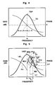
- Fig. 4 shows characteristic curves which represent a total gain-frequency characteristic and total phase-frequency characteristic, which are obtained by combining the gain-frequency characteristics and the phase-frequency characteristics of the self-oscillating circuit and gain variation compensating circuit.
- Fig. 5 shows characteristic curves representing gain-frequency and phase-frequency characteristics of the self-oscillating circuit and gain variation compensating circuit.
- Fig. 6 shows characteristic curves representing gain-frequency and phase-frequency characteristics of the self-oscillating circuit and gain variation compensating circuit.
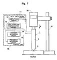
- Fig. 7 shows the structure of an actual system for measuring the hardness of a subject.
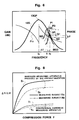
- Fig. 8 shows variations in resonance frequency and detection voltage plotted against compressive force.
- Fig. 9 shows gain-frequency characteristic curves of a hardness measuring apparatus according to a modification of Embodiment 1.
- Fig. 10 shows gain-frequency characteristic curves of a hardness measuring apparatus according to a modification of Embodiment 1.
- Fig. 11 shows the overall structure of a hardness measuring apparatus according to Modification 2 of Embodiment 1.
- Fig. 12 shows the overall structure of a hardness measuring apparatus according to Modification 3 of Embodiment 1.
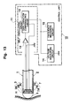
- Fig. 13 shows the overall structure of a hardness measuring apparatus according to Modification 3 of Embodiment 1.
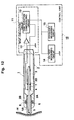
- Fig. 14 shows the overall structure of a hardness measuring apparatus for palpation of internal organs according to Embodiment 2.
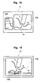
- Fig. 15 shows an image displayed on a monitor.
- Fig. 16 shows an image displayed on a monitor.
- Fig. 17 shows gain-frequency and admittance-frequency characteristic curves.
- Fig. 18 shows the system structure of a hardness measuring apparatus for palpation of internal organs according to Embodiment 2.
- Fig. 19 shows a cross-sectional view of a biological tissue (subject) for explaining the operation of a main probe.
- Fig. 20 shows a magnified view of a hardness information display area.
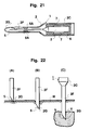
- Fig. 21 shows a partial cross-sectional view of the tip of a main probe.
- Fig. 22 shows cross-sectional views of a main probe and the main part of a subject in the respective steps of palpation.
- Fig. 23 shows a graph displayed in a hardness information display area.
- Fig. 24 shows the overall structure of a hardness measuring apparatus for palpation of internal organs according to Modification 2 of Embodiment 2.
- Fig. 25 shows a magnified cross-sectional view of a touch section of a soft main probe.
- Fig. 26 shows a cross-sectional view of a fiberscope unit and a biological tissue.
- Fig. 27 shows the overall structure of a hardness measuring apparatus for palpation of internal organs according to Modification 3 of Embodiment 2.
- Fig. 28 shows gain-frequency and admittance-frequency characteristic curves of a hardness measuring apparatus for palpation of internal organs according to Modification 4 of Embodiment 2.
- Fig. 29 shows gain-frequency and admittance-frequency characteristic curves of a hardness measuring apparatus for palpation of internal organs according to Modification 5 of Embodiment 2.
- Fig. 30 shows a magnified cross-sectional view of the main part of a main probe of a hardness measuring apparatus for palpation of internal organs according to Modification 6 of Embodiment 2.
- Fig. 31 shows a magnified cross-sectional view of the main part of a main probe of a hardness measuring apparatus for palpation of internal organs according to Modification 7 of Embodiment 2.
- Fig. 32 shows a magnified cross-sectional view of the main part of a soft main probe of a hardness measuring apparatus for palpation of internal organs according to Modification 8 of Embodiment 2.
- Fig. 33 shows a magnified cross-sectional view of the main part of a main probe of a hardness measuring apparatus for palpation of internal organs according to Modification 9 of Embodiment 2.
- Fig. 34 shows the system structure of an acceleration measuring apparatus according to Embodiment 3 of the present invention.
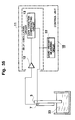
- Fig. 35 shows the system structure of a fluid viscosity measuring apparatus according to Embodiment 3 of the present invention.
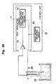
- Fig. 36 shows the system structure of a fluid viscosity measuring apparatus according to a modification of Embodiment 3 of the present invention.
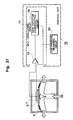
- Fig. 37 shows the system structure of a fluid pressure measuring apparatus according to Embodiment 3 of the present invention.
- Fig. 38 shows the system structure of a fluid pressure measuring apparatus according to a modification of Embodiment 3 of the present invention.
- a hardness measuring apparatus utilizing a frequency deviation circuit is described.
- Fig. 1 shows the overall structure of a hardness measuring apparatus according to Embodiment 1 of the present invention.
- the hardness measuring apparatus has a hand piece 1 and a control unit disposed outside the hand piece 1.
- the hand piece 1 has a casing 2 formed in a substantially cylindrical shape having a bottom.
- An oscillator 3 is disposed inside the middle portion of the casing 2.
- the oscillator 3 has a cylindrical shape.
- a piezoelectric ceramic oscillator is used as the oscillator 3.
- Fig. 2 shows a cross-sectional view of the main part of the oscillator 3.
- the oscillator 3 comprises a first electrode 3A used as an anode, a second electrode 3C used as a cathode, and a piezoelectric crystal 3B formed between the first and second electrodes 3A and 3C.
- the piezoelectric crystal 3B has a cylindrical shape.
- the first electrode 3A is formed on the inner surface of the piezoelectric crystal 3B in a cylindrical shape.
- the second electrode 3C is formed on the outer surface of the piezoelectric crystal 3B in a cylindrical shape, and grounded.
- a voltage varying with time is applied between the first and second electrodes 3A and 3C, causing mechanical oscillation of the piezoelectric crystal 3B.
- any of a quartz oscillator, a PVDF-based oscillator, a magnetostrictive element or a surface acoustic wave (SAW) element can be used as the oscillator 3, instead of the piezoelectric ceramic oscillator.
- the oscillator 3 is mechanically coupled with a contact element 5 via an oscillation conducting member 4.
- An end portion of the oscillation conducting member 4, which extends inside the casing 2 toward its open end, is coaxially fixed on the inner surface of the second electrode 3C at a middle portion of the oscillator 3 with adhesive.
- the other end of the oscillation conducting member 4 is coupled with the contact element 5 with adhesive.
- the contact element 5 is a cylinder having one closed end (tip portion), which is in contact with a subject H.
- the contact element 5 has a hole 5A at the center of the tip portion.
- the oscillation conducting member 4 is inserted into the hole 5A.
- the hole 5A of the contact element 5 and oscillation conducting member 4 are fixed with adhesive.
- the contact element 5 is disposed inside an oscillation maintaining hole 2A formed at the end portion of the casing 2 facing toward the subject H.
- the tip portion of the contact element 5 facing toward the subject H projects from the end portion of the casing 2.
- the contact element 5 disposed inside the oscillation maintaining hole 2A can freely oscillate in the axial direction.
- a groove 2B is formed on the inner surface of the oscillation maintaining hole 2A along its circumference.
- An elastic member 6 is put in the groove 2B.
- the contact element 5 is retained in the oscillation maintaining hole 2A of the casing 2 via the elastic member 6.
- the oscillation to be conducted to the contact element 5 from the oscillator 3 via the oscillation conducting member 4 is absorbed by the elastic member 6, and consequently it is not conducted to the hand piece 1.
- the elastic member 6 works as a node of the oscillation of an electromechanical oscillation system described later.
- the node is formed at a connecting point of the oscillation conducting member 6 and the contact element 5, between the casing 2 and the contact element 5.
- the elastic member 6 is not always disposed at this position, and can be disposed between the electromechanical oscillation system and casing 2 at such a position that the oscillation of the electromechanical oscillation system is not conducted to the casing, and the casing 2 does not adversely affect the oscillation of the electromechanical oscillation system.
- a detecting element 7 is placed on the outer surface of the oscillator 3 inside the casing 2.
- the detecting element 7 comprises a first electrode 7A used as a cathode, a second electrode 7C used as an anode, and a piezoelectric crystal 7B formed between the first and second electrodes 7A and 7C.
- An electrode cylindrically formed on the outer surface of the oscillator 3 is commonly used as the first electrode 7A of the detecting element 7 and the second electrode 3C of the oscillator 3.
- the piezoelectric crystal 7B is formed on the outer surface of the first electrode in a cylindrical shape.
- the second electrode 7C is formed on the outer surface of the piezoelectric crystal 7B in a cylindrical shape.
- the detecting element 7 basically comprises piezoelectric ceramic, as the oscillator 3.
- the detecting element 7 oscillates in synchronism with the oscillation of the oscillator 3, and is used as a sensor for detecting the oscillation as an electrical signal.
- the detecting element 7 outputs hardness information capable of monitoring the oscillation amplitude, frequency and phase of the oscillator 3 as a detection voltage.
- a control unit 10 of the hardness measuring apparatus comprises a self-oscillating circuit 11, a gain variation compensating circuit 13, a voltage measuring circuit 14 and a frequency measuring circuit 15.
- the self-oscillating circuit 11 has an amplifying circuit 12, whose input terminal is connected to the output terminal (second electrode 7C) of the detecting element 7.
- the input terminal of the amplifying circuit 12 is connected to the input terminal (first electrode 3A) of the oscillator 3 via the gain variation compensating circuit 13.
- the self-oscillating circuit 11 has the oscillator, detecting element 7 and amplifying circuit 12.
- the detecting element 7 detects oscillation information of the oscillator 3, and converts it into an electrical signal.
- the amplifying circuit 12 amplifies the electrical signal.
- the amplified electrical signal is fed back to the oscillator 3, leading to the formation of a feedback loop.
- the self-oscillating circuit 11 feeds back the oscillation information of the oscillator 3 via the detecting element 7 and amplifying circuit 12, forming an electrical oscillation system setting the oscillator 3 in a resonant state.
- the oscillator 3, oscillation conducting member 4 and contact element 5 form a mechanical oscillation system in which the oscillation information of the oscillator 3 is conducted to a subject H via the oscillation conducting member 4 and contact element 5.
- the electrical and mechanical oscillation systems are combined into an electromechanical oscillation system.
- the gain of the self-oscillation circuit 11 is almost proportional to the driving voltage of the self-oscillation circuit 11.
- the input terminal of this self-oscillating circuit 11 (input terminal of the electromechanical oscillation system) corresponds to the output terminal of the oscillator 3.
- the output terminal of the self-oscillating circuit 11 (output terminal of the electromechanical oscillation system) corresponds to the input terminal of the oscillator 3.
- the gain variation compensating circuit 13 increases the gain in response to a change in the resonance frequency of the electromechanical oscillation system, and has a function of increasing a detection voltage with an increase in the gain.
- the gain variation compensating circuit 13 has a phase transfer function of adjusting the difference between the input and output phases, called phase difference, of the self-oscillating circuit 11 to zero, and of promoting feedback oscillation, shifts the central frequency so that the phase difference becomes zero, and increases the gain in response to the change in the central frequency.
- a filter circuit having a frequency-gain characteristic realizing a change in the gain in response to a change in frequency is used as the gain variation compensating circuit 13.
- Fig. 3 shows the structure of an example of the filter circuit used as the gain variation compensating circuit 13.
- This filter circuit has resistance elements R1, R2, R3 and R4, capacitance elements C1, C2, C3 and C4 and an amplifying circuit AMP.
- the resistance of the resistance element R1 is set at 10 k ⁇ , that of the resistance element R2 at 220 ⁇ , that of the resistance element R3 at 470 k ⁇ , and that of the resistance element R4 at 2.2 k ⁇ .
- a voltage of 12 V is supplied to the power terminal V1 of the amplifying circuit AMP.
- a reference supply voltage of - 12 V is supplied to a reference supply voltage terminal V2.
- V in shown in Fig. 3 denotes the input terminal for a signal, and V out the output terminal.
- This filter circuit can work as a band-pass filter circuit.
- the input terminal V in of the filter circuit is connected to the output terminal of the amplifying circuit 12 included in the self-oscillating circuit 11.
- the output terminal V out is connected to the first electrode 3A (input terminal) of the oscillator 3.
- the gain variation compensating circuit 13 can be disposed between the oscillator 3 and amplifying circuit 12 of the self-oscillating circuit 11.
- the input terminal V in of the filter circuit is connected to the second electrode 7C (output terminal of the oscillator 3) of the detecting element 7.
- the output terminal V out is connected to the input terminal of the amplifying circuit 12.
- the gain variation compensating circuit 13 is not limited to the band-pass filter circuit. Since any circuit having such a characteristic that it changes the gain in response to a change in frequency, and then increases the detection voltage with the increase in the gain, can be used as the gain variation compensating circuit 13, any of a low-pass filter circuit, high-pass filter circuit, notch filter circuit, integrating circuit, differentiating circuit or peaking amplifying circuit can be used.
- the voltage measuring circuit 14 and frequency measuring circuit 15 of the control unit 10 shown in Fig. 1 are respectively connected to the gain variation compensating circuit 13.
- the voltage measuring circuit 14 and frequency measuring circuit 15 is connected to the output terminal V out of the filter circuit (gain variation compensating circuit 13).
- the voltage measuring circuit 14 is used for measuring a change in the voltage of the electromechanical oscillation system, and the frequency measuring circuit 15 for measuring a change in the frequency of the electromechanical oscillation system.
- the hardness of a subject can be determined by the change in the frequency of the electromechanical oscillation system formed as described above.
- the gain is increased by the gain variation compensating circuit 13, leading to an increased detection voltage.
- the hardness information of a subject can be monitored by the voltage measuring circuit 14 and frequency measuring circuit 15 of the control unit 10.
- the voltage measuring circuit 14 and frequency measuring circuit 15 are not always connected to the output terminal of the gain variation compensating circuit 13. They may be coupled with the electromechanical oscillation system in any manner.
- Fig. 4 shows a total gain-frequency characteristic and a total phase-frequency characteristic, which are obtained by combining the gain-frequency characteristics, and the phase-frequency characteristics of the self-oscillating circuit 11 and gain variation compensating circuit 13.
- the horizontal axis represents frequency, and the vertical axes gain and phase, respectively.
- the characteristic curve TG shows a gain-frequency characteristic of the self-oscillating circuit 11 in which a signal is outputted from the output terminal of the oscillator 3 (actually the output terminal of the detecting element 7), and fed back to the oscillator 3 via the gain variation compensating circuit 13.
- the gain-frequency characteristic curve TG shows a total frequency characteristic obtained by combining the frequency characteristic of the self-oscillating circuit 11 with that of the gain variation compensating circuit 13.
- the gain-frequency characteristic curve TG shows that the gain increases with the increase in frequency in a lower frequency band, has a peak at a resonance frequency f 0 , and then decreases with the increase in frequency in a higher frequency band, making an arched curve.
- the phase characteristic curve ⁇ 11 shows the difference between the input and output phases (phase difference) of the self-oscillation circuit 11.
- the difference between the input and output phases of the self-oscillation circuit 11 is adjusted to zero at a resonance frequency f 0 at which the gain-frequency characteristic curve TG shows a maximum value TGP.
- the gain variation compensating circuit 13 carries out the adjustment of the phase difference ⁇ 11 , and can easily adjust the phase difference ⁇ 11 by shifting the central frequency in the frequency characteristic.
- Fig. 5 shows characteristic curves representing gain-frequency and phase-frequency characteristics of the self-oscillating circuit 11 and gain variation compensating circuit 13.
- the horizontal axis represents frequency, and the vertical axes represent gain and phase, respectively.
- the characteristic curve 13G shows a gain-frequency characteristic of the gain variation compensating circuit 13.
- the gain increases with the increase in frequency in a lower frequency band, reaches a maximum value, and then decreases in a higher frequency band, showing an arched curve.
- the characteristic curve ⁇ 13 shows a phase difference between the input and output phases of the gain variation compensating circuit 13.
- the characteristic curve MG shows a gain-frequency characteristic of the self-oscillating circuit, that is, the electromechanical oscillation system itself, not including a characteristic of the gain variation compensating circuit 13.
- the gain-frequency characteristic curve MG is also an arched curve as the frequency characteristic of the gain variation compensating circuit 13, although the central frequency and maximum value of the gain are different. This gain-frequency characteristic curve MG is obtained when the contact element 5 is not in contact with a subject H.
- the central frequency f 2 at which the gain of the gain variation compensating circuit 13 has a maximum value 13PG
- the central frequency f 2 of the gain of the gain variation compensating circuit 13 is set at a lower frequency than the central frequency f 1 of the gain of the electromechanical oscillation system.
- the central frequency f 2 of the gain of the gain variation compensating circuit 13 is set at a higher frequency than the central frequency f 1 of the gain of the electromechanical oscillation system in order to increase the total gain.
- the contact element 5 of a hardness measuring apparatus comes into contact with a soft subject H
- the mechanical or acoustic impedance of the soft subject is increased.
- This causes a change in the oscillation mode of the oscillator 3, leading to a change in the frequency characteristic of the electromechanical oscillation system.
- All the oscillation frequency, gain, phase and oscillation amplitude included in the oscillation information can be varied.
- the oscillation frequency is shifted toward a lower frequency due to the impedance of the soft subject H.
- a maximum value of the gain is originally decreased in general but in contrast, it is increased in a hardness measuring apparatus according to this embodiment due to the gain increasing function of the gain variation compensating circuit 13.
- the maximum value of the gain increases from the maximum value P1 along the gain-frequency characteristic curve 13G of the gain variation compensating circuit 13.
- the central frequency f 1 of the electromechanical oscillation system is changed to a resonance frequency f 11 determined by the impedance of the subject H.
- the gain-frequency characteristic curve MG of the electromechanical oscillation system is shifted to a gain-frequency characteristic curve MG1.
- the maximum value P1 of the gain is changed to a maximum value P11, and the gain G1 to G11, leading to an increase in the gain.
- Oscillation information including the changes in the frequency and gain, is detected by the detecting element 7. This oscillation information detected by the detecting element 7 is fed back to the oscillator 3 by the feedback loop of the self-oscillating circuit 11.
- the feedback loop of the self-oscillating circuit 11 has a circuit in which a combination of resistance and capacitance elements is used. Therefore, the phase difference ⁇ between the input phase ⁇ 1 and output phase ⁇ 2 is always non-zero.
- the gain variation compensating circuit 13 has a phase transfer function of adjusting the phase difference ⁇ 11 between the input and output phases of the feedback loop including itself to zero. Therefore, the frequency further changes, and the gain increases until they both reach a stable point in the feedback oscillation at a phase difference ⁇ 11 of zero.
- the gain-frequency characteristic curve MG1 of the electromechanical oscillation system is changed to a gain-frequency characteristic curve MG2, and the resonance frequency f 11 to a resonance frequency f 12 .
- the maximum value P11 of the gain is changed to a maximum value P12, and the gain G11 to a gain G12 in response to the change in the resonance frequency to f 12 , leading to a further increase in the gain.
- the central frequency f 1 of the electromechanical oscillation system is continuously varied to the resonance frequency f 12 by a frequency corresponding to the phase difference ⁇ , and the gain G1 is continuously increased to G12. Consequently, a variation ⁇ f in the frequency and a variation ⁇ G in the gain are obtained in the electromechanical oscillation system.
- the phase difference ⁇ 11 between the input and output phases becomes zero, enabling the self-oscillation circuit to carry out feedback oscillation.
- a hardness measuring apparatus detects the variation ⁇ f between the frequencies before and after contacting the contact element 5 with a soft subject H, as hardness information. This enables the hardness of a soft subject H to be measured.
- the hardness measuring apparatus detects the phase difference ⁇ between the phases before and after contacting the contact element 5 with a soft subject H, as hardness information. This also enables the hardness of a soft subject H to be measured.
- the hardness measuring apparatus according to this embodiment enables the gain to be increased in response to the variation ⁇ f and phase difference ⁇ (a sufficient variation ⁇ G in the gain to be obtained), obtaining a detection voltage sufficient for hardness measurement.
- a hardness measuring apparatus when contacting the contact element 5 with a hard subject H, the frequency, gain, phase and oscillation amplitude are changed, but the gain is not increased, because an adjustment appropriate to measuring the hardness of a soft subject H is made.
- Fig. 6 shows gain-frequency characteristic curves and phase-frequency characteristic curves of the self-oscillating circuit 11 and gain variation compensating circuit 13.
- the characteristic curve MG3 shows a gain-frequency characteristic of the electromechanical oscillation system when contacting the contact element 5 with a hard subject H.
- the resonance frequency is changed to a frequency determined by the impedance of the subject H at the instance of contacting.
- the frequency is changed by a frequency corresponding to the phase difference ⁇ to a resonance frequency f 3 at which the phase difference ⁇ 11 between the input and output phases becomes zero, enabling feedback oscillation to be carried out.
- the change in the frequency is shifted toward a higher frequency, and then the variation ⁇ f in the frequency is increased until the phase difference ⁇ 11 becomes zero, leading to a larger value. Consequently, the gain-frequency characteristic curve MG1 of the electromechanical oscillation system is shifted to a gain-frequency characteristic curve MG3.
- the maximum value P1 of the gain is changed to a maximum value P3 at which feedback oscillation is stably carried out.
- the gain variation compensating circuit 13 of a hardness measuring apparatus has both the gain increasing function and phase transfer function.
- the gain variation compensating circuit 13 may have only the gain increasing function.
- an electromechanical oscillation system which includes the oscillator 3, detecting element 7, oscillation conducting member 4 and contact element 5, is oscillated in a resonant state by the self-oscillating circuit 11, so that the hardness measuring apparatus is set in operation.
- Oscillation information that is, the frequency, gain, phase and oscillation amplitude, of this electromechanical oscillation system, is outputted from the output terminal of the gain variation compensating circuit 13.
- the detection voltage is monitored by the voltage measuring circuit 14, and the frequency is monitored by the frequency measuring circuit 15.
- a person measuring the hardness holds the hand piece 1 by hand, and contacts the tip of the contact element 5 oscillating in a resonant state with a subject H.
- the detection voltage and frequency for the electromechanical oscillation system detected by the voltage measuring circuit 14 and frequency measuring circuit 15 respectively, are changed in response to the hardness of the subject H, as follows:
- a highly elastic and soft subject such as a biological soft tissue (human skin, human internal organs) or rubber, has a low mechanical or acoustic impedance, reducing the resonance frequency of the electromechanical oscillation system.
- the electromechanical oscillation system has a gain-frequency characteristic shown by the characteristic curve MG having a maximum value P1 of the gain at a central frequency f 1 before contacting the contact element 5 with the subject H.
- a hardness measuring apparatus has the gain variation compensating circuit 13 which increases the gain in response to a change in the resonance frequency.
- the gain is set to be increased in response to a change in the frequency when contacting the contact element 5 with a soft subject 5.
- the gain-frequency characteristic curve MG of the electromechanical oscillation system is corrected by the gain-frequency characteristic curve 13G of the gain variation compensating circuit when bringing the contact element 5 into contact with a soft subject 5. Consequently, the gain-frequency characteristic curve MG of the electromechanical oscillation system is shifted in the direction indicated by the arrow Q1 shown in Fig. 5.
- the gain variation compensating circuit has the phase transfer function, and the phase difference ⁇ 11 between the input and output phases in the feedback (closed) loop formed by the self-oscillating circuit 11 is adjusted to zero, enhancing the variation in the frequency by a frequency corresponding to a phase difference ⁇ .
- the increase in the gain is enhanced by this change in the frequency.
- the gain-frequency characteristic curve MG is changed into a gain-frequency characteristic curve MG2, and the maximum value P1 of the gain is increased to a maximum value P12.
- a hardness measuring apparatus is set to be suitable for measuring the hardness of a soft subject H.
- the frequency is changed, but the gain is not increased.
- the gain-frequency characteristic curve MG of the electromechanical oscillation system is shifted in the direction indicated by the arrow Q2 to a gain-frequency characteristic curve MG3.
- the gain is decreased, the variation in the frequency is enhanced by the phase transfer function.
- the hardness of a hard subject H can be determined by monitoring this variation in the frequency using the frequency measuring circuit 15.
- the central frequency of the electromechanical oscillation system is set in a lower frequency band, in which the gain is increased with an increase in the frequency, in the gain-frequency characteristic curve 13G of the gain variation compensating circuit 13.
- a change in the voltage of the electromechanical oscillation system is monitored by the voltage measuring circuit 14, and a change in the resonance frequency is monitored by the frequency measuring circuit 15, in order to determine the hardness of a subject.
- Fig. 7 shows the structure of an actual system for measuring the hardness of a subject H.
- the hand piece 1 of a hardness measuring apparatus is coupled with a holding stand 31 via a load cell 30 to be used for measuring the hardness of a subject H.
- the compressive force applied to the subject H by the contact element 5 can be measured by the load cell 30.
- Fig. 8 shows variations in the frequency and detection voltage of a hardness measuring apparatus according to this apparatus and those in a conventional one, which are plotted against the compressive force.
- the horizontal axis indicates a compressive force F measured by the load cell 30, and the vertical axis indicates a variation in the resonance frequency ⁇ f or in the detection voltage ⁇ V.
- Two subjects H A and H B having different hardnesses are used as the subject H.
- the curves S 1 and S 2 show variations in the frequency and voltage in a hardness measuring apparatus according to this embodiment, plotted against the compressive force.
- the curve S 1 shows the variation for the subject H A
- the curve S 2 the variation for the subject H B .
- the curves T 1 and T 2 show variations in the frequency and detection voltage in a conventional hardness measuring apparatus, plotted against the compressive force.
- the curve T 1 shows the variation for the subject H A
- the curve T 2 the variation for the subject H B .
- the variations in the frequency and detection voltage increase with the increase in compressive force to a small extent in a conventional hardness measuring apparatus, and the difference between the variations for the subjects H A and H B is small, even when the hardnesses (acoustic impedance) of the subjects H A and H B are different. Sufficient variations in the frequency and detection voltage for measuring the hardnesses of the subjects H A and H B cannot be obtained.
- the variations in frequency and detection voltage increase with the increase in compressive force to a much larger extent in a hardness measuring apparatus according to this embodiment than the variations in a conventional hardness measuring apparatus, and the difference between the variations for the subjects H A and H B is large.
- a hardness measuring apparatus according to this embodiment can enhance a slight difference between variations in the resonance frequency or detection voltage which is derived from the difference between the hardnesses (acoustic impedances) of subjects.
- a hardness measuring apparatus has the gain variation compensating circuit 13, and the resonance frequency of the electromechanical oscillation system is set in a frequency band in which the gain is increased in response to a change in the frequency of the gain variation compensating circuit 13, the gain is increased in response to a change in the frequency due to a slight difference between the hardnesses of subjects H.
- the phase transfer function of the gain variation compensating circuit 13 enhances the variation in the frequency until the phase difference is cancelled to zero, and further increases the gain. This enables a sufficient detection voltage for determining the hardness of a subject to be obtained.
- the variation in the frequency is enhanced, enabling the measurement of hardness for soft and hard subjects H to be realized in a wide range.
- the effective resonance frequency band of the electromechanical oscillation system of a hardness measuring apparatus is expanded, realizing measurement of the hardness of various subjects H in a wide range.
- the gain variation compensating circuit 13 can be easily achieved by a filter circuit comprising a simple combination of resistance elements, capacitance elements and the like. Complicated circuitry is not necessary for the gain variation compensating circuit 13, enabling a simple structure and fabrication with low cost.
- Figs. 9 and 10 show gain-frequency characteristic curves of a hardness measuring apparatus according to Modification 1 of Embodiment 1.
- Fig. 9 shows gain-frequency characteristic curves when a low-pass filter is used as the gain variation compensating circuit 13.
- a gain-frequency characteristic curve 13G1 of the gain variation compensating circuit 13 and gain-frequency characteristic curve MG of the electromechanical oscillation system are shown.
- a variation in frequency is basically amplified in a similar manner to that in a hardness measuring apparatus including a band-pass filter circuit (see Fig.3).
- the contact element 5 is in contact with a soft subject H, the frequency is changed.
- the variation in the frequency is enhanced, and the gain is increased by the variation in the frequency.
- the gain variation compensating circuit 13 has both the gain increasing function and the phase transfer function. The both functions enables a larger variation in the frequency and a larger gain.
- Fig. 10 shows gain-frequency characteristic curves when a high-pass filter circuit is used as the gain variation compensating circuit 13.
- a gain-frequency characteristic curve 13G2 of the gain variation compensating circuit 13 and gain-frequency characteristic curve MG of the electromechanical oscillation system are shown.
- This hardness measuring apparatus is suitable for measuring the hardness of a hard subject H, such as a metal like iron or an alloy, and a human hard tissue such as a bone or tooth.
- a hard subject H such as a metal like iron or an alloy
- a human hard tissue such as a bone or tooth.
- a gain-frequency characteristic curve MG when the contact element 5 is not in contact with a hard subject is shifted to a gain-frequency characteristic curve MG3.
- a detection voltage sufficient for the measurement of hardness can be obtained by increasing the gain.
- the gain-frequency characteristic curve MG of the electromechanical oscillation system is shifted to a gain-frequency characteristic curve MG1, decreasing the gain.
- Fig. 11 shows the overall structure of a hardness measuring apparatus according to Modification 2 of Embodiment 1.
- This hardness measuring apparatus includes an oscillator 3 comprising a layered piezoelectric ceramic oscillator and a detecting element 7 comprising a film bimorph oscillator. These oscillator 3 and detecting element 7 form the electromechanical oscillation system.
- a ring-shaped piezoelectric ceramic is fixed around an oscillation conducting member 4 with adhesive, and is layered numerous times in the axial direction of the oscillation conducting member 4.
- the size of the layered piezoelectric ceramic oscillator is small, and an input voltage of large amplitude can be obtained.
- the detecting element 7 comprising the bimorph oscillator is fixed on the outer surface of the oscillator 3 (layered piezoelectric ceramic oscillator).
- the detecting element 7 fabricated in a film form has a small weight, and only requires a small space in the casing 2 of the hand piece 1 for disposition.
- An oscillator comprising a PVDF film can be used in the detecting element 7 instead of the bimorph oscillator.
- a hardness measuring apparatus having such a structure includes the oscillator 3 comprising a layered piezoelectric ceramic oscillator and the detecting element 7 comprising a film bimorph oscillator. Therefore, it has the advantage obtained by the hardness measuring apparatus shown in Fig. 1, and also its oscillator 3 outputs a sufficiently large amplitude, enabling the size and weight to be reduced.
- the detecting element 7 of the hardness measuring apparatus is fabricated in a film form, also enabling its size and weight to be reduced. Consequently, the size and weight of composite elements inside the hand piece 1 can be reduced, enabling the size and weight of the hand piece 1 itself to be reduced.
- the operability of the hand piece 1, that is, of the hardness measuring apparatus can be improved.
- Fig. 12 shows the overall structure of a hardness measuring apparatus according to Modification 3 of Embodiment 1.
- This hardness measuring apparatus includes an oscillator 3 comprising a layered piezoelectric ceramic oscillator, a detecting element 7 comprising a layered piezoelectric ceramic oscillator and an insulation material 3D. These oscillator 3 and detecting element 7 form the electromechanical oscillation system.
- a ring-shaped piezoelectric ceramic is fixed around an oscillation conducting member 4 with adhesive, and is layered numerous times in the axial direction of the oscillation conducting member 4.
- the size of the layered piezoelectric ceramic is small, and an input voltage of large amplitude can be obtained.
- the layered piezoelectric ceramic oscillator comprising the detecting element 7 is disposed closer to the contact element 5 than to the oscillator 3.
- a ring-shaped piezoelectric ceramic is fixed around an oscillation conducting member 4 with adhesive, and is layered numerous times in the axial direction of the oscillation conducting member 4.
- the insulation material 3D is disposed between the oscillator 3 and detecting element 7.
- the oscillator 3 of the layered piezoelectric ceramic oscillator, insulation material 3D and detecting element 7 are fabricated as an integrated assembly.
- a hardness measuring apparatus having such a structure includes the oscillator 3 comprising layered piezoelectric ceramic oscillator and the detecting element 7 comprising a film bimorph oscillator. Therefore, it has the advantage obtained by the hardness measuring apparatus shown in Fig. 1, and also its oscillator 3 outputs a sufficiently large amplitude, enabling the size and weight to be reduced.
- the detecting element 7 of the hardness measuring apparatus is fabricated in a film form, also enabling its size and weight to be reduced. Consequently, the size and weight of composite elements inside the hand piece 1 can be reduced, enabling the size and weight of the hand piece 1 itself to be reduced.
- the operability of the hand piece 1, that is, of the hardness measuring apparatus can be improved.
- Fig. 13 shows the overall structure of a hardness measuring apparatus according to Modification 3 of Embodiment 1.
- This hardness measuring apparatus includes a cylindrical-shaped casing 2 of a hand piece 1.
- a hemi-spherical tip of a contact element 5 fits into an end of the casing 2.
- An oscillator 3 is disposed on a flat surface of the contact element 5 facing toward the casing 2, and then a detecting element 7 is disposed on the oscillator 3.
- the oscillator 3 comprises a first electrode 3A used as an anode, a second electrode 3C used as a cathode and a piezoelectric crystal 3B formed between the first and second electrodes 3A and 3C, as in the hardness measuring apparatus shown in Fig.1.
- a detecting element 7 comprises a first electrode 7A used as a cathode, a second electrode 7C used as an anode and a piezoelectric crystal 7B formed between the first and second electrodes 7A and 7C.
- Each layer of these first electrode 3A, piezoelectric crystal 3B, second electrode 3C, first electrode 7A, piezoelectric crystal 7B and second electrode 7C can be easily fabricated with a fine pattern by a film fabricating method, such as sputtering used in semi-conductor production.
- the sequence of the layers of the oscillator 3 and detecting element 7 can be reversed.
- the oscillator 3 can be easily made by laminating a sheet-formed piezoelectric material, such as piezoelectric ceramic or oscillating quartz, with adhesive.
- a hardness measuring apparatus having such a structure includes the hemi-spherical contact element 5.
- the oscillator 3 and detecting element 7 are directly fabricated on the flat surface of the contact element facing toward the casing 2 as an integrated assembly.
- the mechanical oscillation part of the electromechanical oscillation system which is in contact with a subject H, can be significantly reduced in size and weight.
- the measuring section can be fabricated in a small size, enabling the hardness measuring apparatus to be used for measuring the hardness of a small subject, such as a biological tissue.
- the contact element 5 and oscillator 3 can be formed as an integrated assembly.
- the oscillation of the oscillator 3 is directly conducted to a subject H.
- the feedback loop of a phase-lock loop (PLL) circuit can be used instead of the feedback loop of the self-oscillating circuit 11.
- Embodiment 2 a hardness measuring apparatus for measuring the hardness of a biological tissue in a human living body, in which a frequency deviation circuit is used, will be described.
- Fig. 14 shows the overall structure of a hardness measuring apparatus for palpation of internal organs according to Embodiment 2.
- the hardness measuring apparatus has a main probe 1 used for palpation of internal organs and a control unit 10 placed outside the main probe 1.
- the main probe 1 of the hardness measuring apparatus for palpation of internal organs has a casing 2, which is formed by a tubular pipe insertable into a living body (for example, a human body).
- the casing 2 has a touch section 2C which is brought into contact with a subject H (living body), a middle section in its middle portion and a hold section 2E held by a person carrying out the measurement.
- the outer diameters of the touch and hold sections 2C and 2E are a little larger than that of the middle section 2D. Since the casing 2 is inserted into a living body, it is made of a highly rigid and corrosion resistive material, such as stainless steel.
- An oscillator 3 for generating ultrasonic oscillation and a detecting element 7 for detecting oscillation are disposed inside the touch section 2C of the casing 2.
- the oscillator 3 comprises a piezoelectric ceramic oscillator, as in the hardness measuring apparatus according to Embodiment 1.
- the oscillator 3 is brought into contact with a subject H of a biological tissue in a living body.
- a contact element 5 (touch member) is mechanically coupled with the subject H whose hardness is to be measured.
- the tip of the contact element 5 sticks out from an opening formed at the end of the touch section 2C of the casing 2.
- the tip of the contact element has a hemi-spherical shape.
- the contact element 5 is widely usable for contacting with a subject H both at a point and over an area.
- the detecting element 7 is fixed on the oscillator 3, and detects the oscillation of the oscillator 3.
- the detecting element 7 comprises piezoelectric ceramics, as the oscillator 3.
- the detecting element 7 is integrated with the oscillator 3, as in the hardness measuring apparatus according to embodiment 1. Alternatively, the detecting element 7 can be separately fabricated, and then mechanically coupled with the oscillator 3.
- an elastic member 6 is disposed between the inner surface of the touch section 2C and oscillator 3, or detecting element 7.
- the elastic member 6 retains the electromechanical oscillation system comprising the oscillator 3, detecting element 7 and contact element 5, and absorbs the oscillation generated by the electromechanical oscillation system and proceeding toward the casing 2.
- the elastic member 6 is made of silicone rubber. Any oscillation absorbing material of urethane resin, fluororubber or nitrile rubber (NBR) can be used as the elastic member 6.
- the control unit 10 has a self-oscillating circuit 11, a gain variation compensating circuit 13, a frequency counter circuit 15, a controller circuit 16, a monitor 17 and a fiberscope unit 18.
- the self-oscillating circuit 11 of the control unit 10 has an amplifying circuit 12.
- the amplifying circuit 12 is disposed inside the hold section in a hardness measuring apparatus for palpation of internal organs according to this embodiment.
- the input terminal of the amplifying circuit 12 is connected to the output terminal of the detecting element 7.
- the output terminal is connected to the input terminal of the oscillator 3 via the gain variation compensating circuit 13.
- the amplifying circuit 12 amplifies oscillation information outputted from the detecting element 7.
- the amplified oscillation information is fed back to the oscillator 3 to form a feedback loop.
- the mechanical oscillation system comprising the oscillator 3, detecting element 7 and contact element 5, and the electrical oscillation system comprising the self-oscillating circuit 11 form an electromechanical oscillation system.
- the self-oscillating circuit 11 oscillates the oscillator 3 in a resonant state, and the oscillator 3 oscillates the contact element 5.
- the contact element 5 is brought into contact with a subject H
- the mechanical or acoustic impedance of the subject H changes the oscillation mode of the oscillator 3. This causes a change in the frequency characteristic of the electromechanical oscillation system.
- the hardness of the subject H can be determined by the change in the frequency characteristic.
- the gain variation compensating circuit 13 is connected between the amplifying circuit 12 and oscillator 3.
- the gain variation compensating circuit 13 has a gain increasing function of increasing the gain in response to a change in the frequency characteristic of the electromechanical oscillation system according to a principle of basic operation similar to that of the hardness measuring apparatus according to Embodiment 1.
- the gain variation compensating circuit 13 also has a phase transfer function of adjusting the difference between the input and output phases (phase difference) of the self-oscillating circuit 11, and of promoting feedback oscillation.
- the input terminal of the frequency counter circuit 15 is connected to the output terminal of the gain variation compensating circuit 13.
- the frequency counter circuit measures the frequency of the electromechanical oscillation system.
- the input terminal of the controller circuit 16 is connected to the output terminal of the frequency counter circuit 15.
- the controller circuit 16 generates an image.
- the frequency counter circuit 15 measures the difference between the frequencies of the electromechanical oscillation system before and after the contact element 5 in a resonant state becomes in contact with a subject H.
- the controller circuit 16 detects the difference in the frequency of the electromechanical oscillation system from the data measured by the frequency counter circuit 15. Hardness information representing the mechanical property of the subject H is obtained in the controller circuit 16.
- the fiberscope unit 18 and monitor 17 are connected to the controller circuit 16.
- the fiberscope unit 18 images a location whose hardness is to be measured. Obtained image data (image data generated by endoscopic image or observation image) are outputted to the controller circuit 16.
- an endoscope is used as the fiberscope unit 18.
- the monitor 17 combines the image data from the fiberscope unit 18 and hardness information based on the measured data from frequency counter circuit 15.
- the monitor 17 displays the combined hardness information as an image.
- Fig. 15 shows an image displayed on the monitor 17.
- the screen of the monitor 17 is divided into two areas 17A and 17B, one is an endoscopic image display area 17A, the other is a hardness information display area 17B.
- an endoscopic image taken by the fiberscope unit 18 is displayed in the endoscopic image display area 17A.
- an image showing that the main probe 1 is in contact with a subject H is displayed in the endoscopic image display area 17A.
- a graph representing the hardness of the subject H is displayed in the hardness information display area 17B.
- Fig. 16 shows another image displayed in the monitor 17.
- the monitor 17 has the endoscopic image display area 17A and hardness information display area 17B, and a specific part of the endoscopic image display area 17A (for example, a lower-left part) overlaps the hardness information display area 17B.
- Fig. 17 shows gain-frequency and admittance-frequency characteristic curves of the electromechanical oscillation system and gain variation compensating circuit 13.
- the horizontal axis indicates frequency, and vertical axes respectively indicate gain and admittance of the oscillation system.
- the characteristic curve MG shows a gain-frequency characteristic (admittance-frequency characteristic) of the electromechanical oscillation system excepting the gain variation compensating circuit 13 when the contact element 5 is not in contact with a subject H.
- the characteristic curve 13G shows a gain-frequency characteristic of the gain variation compensating circuit 13.
- a band-pass filter circuit is used, as in a hardness measuring apparatus according to Embodiment 1.
- the gain-frequency characteristic curve 13G of the gain variation compensating circuit 13 is set in a frequency band in which the gain of the electromechanical oscillation system is changed in response to a change in the frequency.
- a central frequency f 2 at which the gain has a maximum value 13GP in the gain-frequency characteristic curve 13G of the gain variation compensating circuit 13, is lower than a central frequency f 1 at which the gain in the characteristic curve MG of the electromechanical oscillation system has a maximum value P1 (maximum value of the admittance). Therefore, the electromechanical oscillation system resonantly oscillates at a frequency lower than the central frequency f 1 , and higher than the central frequency f 2 , when the contact element 5 is in contact with subject H.
- a hardness measuring apparatus for palpation of internal organs according to Embodiment 2 has a characteristic shown by a gain-frequency characteristic curve MG5, when the contact element 5 of the main probe 1 is not in contact with anything.
- the gain-frequency characteristic curve MG5 has a maximum value P5 at a central frequency f 5 .
- the gain-frequency characteristic curve MG5 is changed to a gain-frequency characteristic curve MG6. Because the acoustic impedance of the subject H is low, the central frequency f 5 is shifted toward a lower frequency, and becomes stable at a frequency f 6 .
- the gain is increased along the gain-frequency characteristic curve 13G of the gain variation compensating circuit 13 by the gain increasing and phase transfer functions of the gain variation compensating circuit 13, leading to the obtaining of a maximum value P5 of the gain.
- This increased gain enables a sufficient detection voltage for hardness measurement to be obtained.
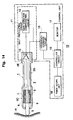
- FIG. 18 shows the system structure of a hardness measuring apparatus for palpation of internal organs according to this embodiment.
- the fiberscope unit 18 is inserted into the thoracic cavity X of a human body (subject) through an opening formed on the surface of a thoracic part.
- the fiberscope unit 18 sends an endoscopic image in the thoracic cavity to the controller circuit 16 as image data, the controller circuit 16 generates an endoscopic image, which is displayed in the endoscopic image display area 17A of the monitor 17.
- a person carrying out the measurements can observe the endoscopic image in a field of view by looking at the endoscopic image displayed in the endoscopic image display area 17A of the monitor 17.
- Another opening is formed on the surface of the thoracic part of the subject.
- a probe guide 19 is inserted through the opening.
- the main probe 1 of the hardness measuring apparatus for palpation of internal organs is inserted into the thoracic cavity X via the probe guide 19.
- the measurer contacts the contact element 5 disposed at the tip of the main probe 1 inserted into the thoracic cavity with the objective subject H (lung) in the human body, while observing the endoscopic image display area 17A of the monitor 17.
- the endoscopic image display area 17A an endoscopic image showing that the contact element 5 is in contact with the objective subject H can be observed.
- a hardness measuring apparatus for palpation of internal organs Using a hardness measuring apparatus for palpation of internal organs according to this embodiment, at the instant the contact element 5 is brought into contact with a subject H, the hardness of the subject H can be measured from a change in the frequency of the electromechanical oscillation system. A result of this, a hardness measurement is displayed in the hardness information display area 17B of the monitor as hardness information.
- Fig. 19 shows a cross-sectional view of a biological tissue (subject H) for explaining the operation of the main probe 1.
- Fig. 20 shows a magnified view of the hardness information display area 17B representing the hardness information corresponding to a cross-section of a biological tissue.
- the contact element 5 of the main probe is slid in the direction indicated by the arrow, keeping contact with the subject H.
- the hardness measuring apparatus for palpation of internal organs measures the hardness of the subject H in the range of the sliding.
- a tumor Y such as a cancer exists on the surface of a lung (subject H) or in a deeper part of a pulmonary tissue
- the tissue is usually harder than a normal pulmonary tissue.
- the contact element 5 of the main probe 1 moves from a normal tissue to the tumor, the hardness of the subject H shown in the hardness information display area 17B increases, as shown in Fig. 20.
- the tumor Y located in the pulmonary tissue can be detected, and its position can also be identified.
- a hardness measuring apparatus for palpation of internal organs can be used for measuring the hardness of a liver (for example, a liver suffering from cirrhosis) or a muscle tissue.
- the biological tissue in a living body to which the hardness measuring apparatus for palpation of internal organs is applied is not limited.
- a hardness measuring apparatus for palpation of internal organs can be used for measuring the hardness of animal or plant tissues.
- a hardness measuring apparatus for palpation of internal organs has the gain variation compensating circuit 13.
- the gain increasing and phase transfer functions of the gain variation compensating circuit 13 increases the gain in response to a change in the frequency. This enables a sufficient detection voltage for hardness measurement to be obtained. A slight difference in the hardness of a subject can be detected to precisely determine the hardness.
- the phase transfer function of the gain variation compensating circuit 13 changes the frequency, and increases the gain until a slight difference between the phases becomes zero, where the feedback oscillation is stably carried out. This enables a sufficient detection voltage for hardness measurement to be obtained.
- the frequency is changed, a variation in the frequency is enhanced, and then the gain is increased in response to the enhanced variation in the frequency.
- This enables a detection voltage sufficient for hardness measurement to be obtained. Therefore, the hardness of various soft and hard subjects can be measured in a wide range of hardness.
- the effective resonance frequency band of the electromechanical oscillation system is widened, and the hardness of various soft and hard subjects H can be measured.
- the gain variation compensating circuit 13 can be easily realized by a filter circuit comprising a simple combination of resistance elements and capacitance elements. This does not require a complicated circuit structure, enabling the system to be simple and fabricated with low cost.
- a hardness measuring apparatus for palpation of internal organs can detect a tumor Y located on the surface or at a deeper position of a biological tissue by bringing the contact element 5 of the main probe 1 inserted into a living body into contact with a biological tissue (subject H) in the living body, and identifying the position of the tumor Y. Therefore, medical diagnosis of a disease, such as cancer, a tumor or cirrhosis, can be easily carried out.
- the hardness measuring apparatus for palpation of internal organs easily realizes palpation similar to that conducted by a physician with high accuracy. This enables an early prophylaxis.
- a hardness measuring apparatus for palpation of internal organs has the endoscopic image display area 17A and hardness information display area 17b in the monitor 17 of the control unit 10, the contact of the main probe 1 with a biological tissue (subject H) in a living body is confirmed by an endoscopic image displayed in the endoscopic image display area 17A. At the same time, measurement of the hardness (diagnosis) of the biological tissue can be carried out. This always enables the measurement of hardness to be performed at a correct location safely and with high efficiency.
- the hardness measuring apparatus for palpation of internal organs can be used for measuring the hardness of a biological tissue located not only within a living body, but also that located on the surface of the living body, such as skin, as a hardness measuring apparatus for ectal organs.
- the hardness of an ectal biological tissue (subject H), such as skin, which is treated with an electrical cautery, laser treatment device or microwave treatment device can be measured by this hardness measuring apparatus for ectal organs.
- the postoperative healing of the treated tissue can be easily monitored by continuously measuring the hardness of the treated tissue.
- a layered piezoelectric ceramic oscillator, bimorph oscillator, quartz oscillator, PVDF-based oscillator, magnetostrictive element or SAW element can be used as the oscillator 3 instead of the piezoelectric ceramic oscillator, as in a hardness measuring apparatus according to Embodiment 1.
- a layered piezoelectric ceramic oscillator, bimorph oscillator, quartz oscillator, PVDF-based oscillator, magnetostrictive element or SAW element can also be used as the detecting element 7.
- a low-pass filter circuit, high-pass filter circuit, notch filter circuit, integrating circuit, differentiating circuit or peaking amplifying circuit can be used as the gain variation compensating circuit 13.
- an active filter circuit or passive filter circuit can be used as the gain variation compensating circuit 13.
- a main probe 1 is used instead of the hand piece 1.
- the shape of the tip of the main probe 1 and that of the contact element 5 are changed.
- Fig. 21 shows a partial cross-sectional view of the tip of the main probe 1 of a hardness measuring apparatus for palpation of internal organs.
- the contact element 5 of the hardness measuring apparatus for palpation of internal organs is formed as a contact needle that can puncture a biological tissue.
- An outer needle 2F having a lumen is formed surrounding the contact needle 5 of the main probe 1, which is to be brought into contact with a subject H, in order to protect the contact needle 5.
- a puncture edge 2G is formed at the tip of the outer needle 2F by cutting at a sharp angle to the longitudinal axis, and can puncture a biological tissue in a living body. Only the tip of the contact needle 5 (contact element) sticks out of the puncture edge 2G of the outer needle 2F.
- the contact element 5 is disposed inside the outer needle 2F except its tip, which can be brought into contact with a subject H (biological tissue).
- a supporting member 6A is disposed in a middle portion of the lumen of the outer needle 2F.
- the contact element 5 is held at the central axis of the outer needle 2F by the supporting member 6A, and prevents the contact element 5 from coming into contact with the outer needle 2F.
- the supporting member 6A blocks the inside of the outer needle 2F in order to prevent an unnecessary substance from entering the inside of the main probe 1.
- the supporting member 6A is disposed so that it is a node of the resonance oscillation of the electromechanical system, as it is disposed between the oscillator 3, and detecting element 7 and the casing 2. This enables the oscillation not to be conducted to the casing 2, such as the outer needle 2F, and only the contact element is oscillated.
- the overall structure is the same as that according to Embodiment 2 described before, except for the contact element 5, outer needle 2F, puncture edge 2G and supporting member 6A.
- Fig. 22 shows cross-sectional views of the main probe 1 and the main part of a subject H (biological tissue) in the respective steps of palpation.
- the hardness of the subject H biological tissue
- the outer needle 2F of the main probe 1 punctures the subject H (biological tissue) from the surface a living body, and then the hardness of the subject is measured. Since the outer needle 2F has the puncture edge 2G at its tip, puncture of the biological tissue is smoothly carried out.
- the contact element 5 (contact needle) is placed inside the outer needle 2F, and the hardness of a part of the biological tissue in contact with it is measured.
- the step (C) shows that the contact element 5 reaches a tumor Y located in a deeper part of the biological tissue.
- the frequency of the electromechanical oscillation system is changed.
- the gain variation compensating circuit 13 increases the gain in response to the change in the frequency of the electromechanical oscillation system, leading to the obtaining of a sufficient detection voltage for measuring the hardness of the biological tissue.
- the hardness of the biological tissue is finally displayed in the hardness information display area 17B of the monitor 17 as a graph.
- Fig. 23 shows a graph displayed in the hardness information display area 17B of the monitor 17.
- the vertical axis represents the hardness of a subject H (biological tissue), and the horizontal axis the depth of the subject H from the surface of a living body.
- the puncture edge 2G of the outer needle 2F has just begun to puncture
- the surface of the biological tissue is pressed by the outer needle 2F and elongated. This makes the surface harder. Since the contact element 5 is in contact with the hardened surface, an increased hardness is measured.
- the step (B) during which the puncture of the outer needle 2F into the subject H proceeds, the contact element 5 stays in contact with an internal tissue. A constant and small hardness is measured during this step.
- the contact element 5 reaches a tumor Y and is further inserted into it.
- the puncture edge 2G of the outer needle 2F presses the surface of the tumor Y, which is elongated. This makes the surface harder. Since the contact element 5 is in contact with the hardened surface, an increased hardness is measured. After that, the contact element 5 further proceeds into the tumor Y. A constant hardness larger than that measured for the normal tissue is measured. The hardness of the tumor Y is slightly larger than that of the surrounding normal tissue. The difference between these hardnesses can be surely detected by a hardness measuring apparatus for palpation of internal organs according to Embodiment 2.
- the contact of the outer needle 2F of the main probe 1 with a biological tissue (subject H) is monitored by observing an endoscopic image which is sent from the fiberscope unit 18 and displayed in the endoscopic image display area 17A of the monitor 17 (see Figs. 14, 15 and 18), for example, when puncturing a biological tissue located on the surface of a lung with the outer needle 2F.
- the puncture position of the outer needle 2F on the surface of a lung is displayed in the endoscopic image display area 17A.
- the hardness of the lung in the depth direction at the puncture position can be measured while observing the puncture region. Therefore, a tumor Y can be surely detected and both the position and depth of the tumor Y can be identified.
- a contact needle is used as the contact element 5 of the main probe 1, and it is surrounded by the outer needle 2F having the puncture edge 2G at the tip. This enables the contact element 5 to puncture a deeper part of a biological tissue. Hardness information of the deeper part of a biological tissue can be directly obtained.
- the hardness measuring apparatus for palpation of internal organs according to Embodiment 2 can obtain a sufficient detection voltage for measuring the hardness of a biological tissue, even when the difference between the hardnesses is slight.
- the hardness of a deeper part of a biological tissue can be directly measured by the contact element 5, enabling an affected part of a biological tissue to be detected with high accuracy. This realizes an effective medical prophylaxis.
- the monitor 17 has the two endoscopic image display area 17A and hardness information display area 17B.
- An actual contact position, at which the contact element 5 is in contact with a biological tissue via the outer needle 2F, can be confirmed by observing an endoscopic image displayed in the endoscopic image display area 17A. While observing the endoscopic image, the hardness of a biological tissue, in particular that of a deeper part of the biological tissue, can be measured. This enables a diagnosis of a biological tissue at a correct position safely and with high efficiency.
- a hardness measuring apparatus for palpation of internal organs according to Embodiment 2 is not restrictively used for measuring the hardness of a lung or liver as described before, but can be also used for measuring the hardness of a living tissue of a thyroid gland.
- the outer needle 2F is inserted toward the thyroid gland with puncture, and the contact element is brought into contact with a thyroid gland tissue.
- the contact element 5 is in contact with the thyroid gland tissue, hardness information of the thyroid gland tissue is displayed in the hardness information display area 17B of the monitor 17.
- the fiberscope unit is not needed.
- a hardness measuring apparatus for palpation of internal organs according to Modification 2 of Embodiment 2 is the same as one described in Modification 1 except that a soft main probe 1 used instead of the main probe 1.
- Fig. 24 shows the overall structure of a hardness measuring apparatus for palpation of internal organs according to Modification 2 of Embodiment 2.
- This hardness measuring apparatus for palpation of internal organs has a soft main probe 1 insertable into a cavity in a human body.
- the touch section 2C of the soft main probe 1 is formed by a flexible (soft) tube which can be inserted into a cavity.
- a fluororesin tube is used as the flexible tube.
- a polyvinyl chloride tube, polyurethane tube or coil sheath tube can be used as the flexible tube.
- the soft main probe basically has the touch section 2C and holding section 2E.
- the amplifying circuit 12 of the self-oscillating circuit 11 is disposed inside the holding section 2E, as in the hardness measuring apparatus for palpation of internal organs according to Embodiment 2.
- Fig. 25 shows a magnified cross-sectional view of the touch section 2C of the soft main probe 1.
- the oscillator 3 for generating ultrasonic oscillation is disposed at the tip facing a subject H on the central axis of the soft tube.
- the contact element 5 to be brought into contact with the subject H is placed at the tip of the touch section 2C.
- the contact element 5 has a hemi-spherical shape, and sticks out from the tip toward the subject H.
- the contact element 5 is coupled with the oscillator 3, and the ultrasonic oscillation of the oscillator 3 is conducted to the contact element 5.
- the oscillator 3 is connected to the detecting element 7 detecting the oscillation of the oscillator 3.
- the detecting element 7 is connected to the amplifying circuit 12 of self-oscillating circuit 11 placed inside the holding section 2E of the soft main probe 1.
- the supporting member 6 for supporting the electromechanical oscillation system including the oscillator 3, detecting element 7 and contact element 5 is placed.
- the supporting member 6 holds the electromechanical oscillation system at the axial center of the touch section 2C, and prevents the oscillation of the mechanical oscillation system from being conducted to the touch section 2C.
- a round ring-shaped supporting member is used as the supporting member 6. The contact areas between the oscillator 3 and supporting member 6, and the supporting member 6 and the inner surface of the touch section 2C are set smaller.
- the oscillator 3 is fairly flexibly supported to enable it to follow the bending of the touch section 2C to some extent. This keeps the oscillator 3 from being excessively pressed and adversely affected from outside.
- the supporting member 6 is made of a rubber material, such as silicone rubber or NBR, or of a resin material, such as polyurethane resin or fluororesin.
- Fig. 26 shows a cross-sectional view of the fiberscope unit 18 having the soft main probe 1 and a biological tissue into which the fiberscope unit 18 is inserted.
- the touch section 2C of the hardness measuring apparatus for palpation of internal organs, formed by a soft tube, is inserted into an instrument guide channel 18A of the fiberscope unit 18, and introduced to a cavity through the instrument guide channel 18A.
- a fiberscope unit having a flexible structure, such as a digestive tract videoscope or digestive tract fiberscope, is used as the fiberscope 18.
- the fiberscope unit 18 has an insertion section 18B which can be inserted into a cavity.
- a tip section 18D is coupled with the tip of the insertion section 18B facing the cavity via a flexible tube section 18C.
- the flexible tube section 18C connects the insertion section 18B and tip section 18D, and permits the tip section 18D to freely turn around the insertion section 18B.
- the end surface of the tip section 18D has an exit of the instrument guide channel 18A, an illumination window 18E of a light guide for introducing illumination light and an observation window 18F coupled with observation optics.
- the touch section 2C of the soft main probe 1 is formed by a soft tube, and has such an outer diameter that it can be inserted into the instrument guide channel 18A of the fiberscope unit 18 having a flexible structure.
- this hardness measuring apparatus for palpation of internal organs is the same as that of the hardness measuring apparatus for palpation of internal organs according to Embodiment 2 except for the soft main probe and fiberscope unit 18 having a soft structure.
- this hardness measuring apparatus for palpation of internal organs.
- the hardness of the inner surface (subject H) of an esophagus suffering from esophageal varices is measured by this hardness measuring apparatus for palpation of internal organs.
- the insertion section 18B of the soft fiberscope unit 18 is inserted into the esophagus of a patient from his mouth.
- the inner surface of the esophagus is observed by looking at an endoscopic image displayed in the endoscopic image display area 17A.
- the touch section 2C of the soft main probe 1 is inserted into the instrument guide channel 18A of the insertion section 18B of the fiberscope unit 18.
- the tip of the touch section 2C of the soft main probe 1 is stuck out into the esophagus from the exit of the instrument guide channel in the end surface so that the contact element 5 is brought into contact with the varix Z (subject H).
- the flexible tube section 18C is so flexibly bent that the tip section 18D freely turns around. This enables the tip section 18D to freely turn to a place to be observed, and the contact element 5 to freely turn to a place to be diagnosed.
- the frequency counter circuit 15 shown in Fig. 24 measures the frequency of the electromechanical oscillation system.
- the controller circuit 16 detects a change in the frequency of the electromechanical oscillation system, in which the contact element 5 is in contact with the varix Z, by data measured by the frequency counter circuit 15 to obtain hardness information of the varix Z.
- Data of an endoscopic image of the inner surface of the esophagus, which are sent from the fiberscope unit 18, and the hardness information of the varix Z obtained by the data measured by the frequency counter circuit 15 are combined in the controller circuit 16.
- the endoscopic image and hardness information are displayed in the monitor 17, respectively.
- As the monitor 17 of the aforementioned hardness measuring apparatus for palpation of internal organs see Figs.
- the monitor 17 has the two endoscopic image display area 17A and hardness information display area 17B.
- the endoscopic image including the varix Z is displayed in the endoscopic image display area 17A, and the hardness information of the varix Z in the hardness information display area 17B.
- a hardness measuring apparatus for palpation of internal organs according to Modification 2 of Embodiment 2 can be used not only for measuring the hardness of an esophagus, but also for measuring the hardness of a biological tissue of a prostate.
- the contact element 5 of the soft main probe 1 is brought into contact with the prostate (subject H) using a urethroscope.
- a change in the frequency of the electromechanical oscillation system, in which the contact element 5 is in contact with the prostate, is measured by the frequency counter circuit 15.
- the hardness of a biological tissue of the prostate can be determined by measuring the change.
- a result of the hardness measurement is displayed in the hardness information display area 17B of the monitor 17.
- In the endoscopic image display area 17A an endoscopic image of the inner surface of the bladder is displayed.
- this hardness measuring apparatus for palpation of internal organs can be used for measuring the hardness of a biological tissue of a bladder.
- the contact element 5 of the soft main probe 1 is inserted into the inside of a bladder (subject H) using an urethroscope, so that the contact element 5 is brought into contact with the inner surface of the bladder.
- a change in the frequency of the electromechanical oscillation system, in which the contact element 5 is in contact with the inner surface of the bladder, is measured by the frequency counter circuit 15.
- the hardness of a biological tissue of the bladder can be determined by measuring the change.
- a result of the hardness measurement is displayed in the hardness information display area 17B of the monitor 17.
- In the endoscopic image display area 17A an endoscopic image of the inner surface of the bladder is displayed.
- a hardness measuring apparatus for palpation of internal organs according to Embodiment 2 can be used for measuring the hardness of any biological tissues in a human body, as well as those of a human lung, lever, esophagus, prostate and bladder, and for medically diagnosing the tissues. The obtained diagnosis results are useful for treatment and prophylaxis.
- a hardness measuring apparatus for palpation of internal organs having such a structure comprises the soft main probe 1, in which the touch section 2C is formed by a flexible tube, so that the touch section freely turns around.
- the contact element 5 can be inserted into a cavity via the instrument guide channel 18A of the insertion section 18B of the fiberscope unit 18 having a flexible structure.
- the fiberscope section 18 has the flexible tube section 18C at the tip of the insertion section 18B.
- the flexible tube section 18C enables the tip section 18D to freely turn around.
- the contact element 5 can freely move in the cavity due to the free turning of the tip section 18D.
- the illumination window 18E and observation window 18F disposed in the end surface of the tip section 18D of the fiberscope unit 18 can freely turn to a pathological part.
- the contact element 5 can be surely set in contact with the pathological part to measure the hardness of the pathological part.
- This hardness measuring apparatus for palpation of internal organs has the soft main probe 1 which can be inserted into a cavity, enabling the hardness of a biological tissue in the cavity to be measured without performing a painful surgical operation on a patient.
- This hardness measuring apparatus for palpation of internal organs has the endoscopic image display area 17A and hardness information display area 17B in the monitor 17.
- the hardness of an affected part of a biological tissue in a cavity, with which the contact element 5 should be in contact, can be measured while identifying the actual position of the affected part by observing an endoscopic image. This enables a safe diagnosis of a biological tissue at the correct position with high efficiency.
- a hardness measuring apparatus for palpation of internal organs according to Modification 3 of Embodiment 2 has a structure of the control unit 10 partly different from that in the hardness measuring apparatus for palpation of internal organs according to Embodiment 2.
- Fig. 27 shows the overall structure of a hardness measuring apparatus for palpation of internal organs according to Modification 3 of Embodiment 2.
- This hardness measuring apparatus for palpation of internal organs has an amplitude voltage measuring circuit 20 instead of the frequency counter circuit 15.
- Fig. 17 gain-frequency and admittance-frequency characteristic curves shown before, the central frequency f 2 of the gain variation compensating circuit 13 shown in the gain-frequency characteristic curve 13G is set lower than the central frequency f 1 of the electromechanical oscillation system shown in the gain-frequency characteristic curve MG. Therefore, when the contact element 5 is brought into contact with the subject H, the frequency of the electromechanical oscillation system is changed, the gain is increased in response to this change in the frequency, and then the amplitude voltage is increased.
- a hardness measuring apparatus for palpation of internal organs having such a structure has advantages similar to those provided by the aforementioned hardness measuring apparatus for palpation of internal organs according to Embodiment 2.
- the frequency counter circuit 15 in the respective hardness measuring apparatuses for palpation of internal organs according to Modifications 1 and 2 of Embodiment 2 can be replaced with the amplitude voltage measuring circuit 20.
- a low-pass filter circuit is used as the gain variation compensating circuit 13 instead of the band-pass filter circuit.
- Fig. 28 shows gain-frequency and admittance-frequency characteristic curves of the electromechanical oscillation system and gain variation compensating circuit 13 in a hardness measuring apparatus for palpation of internal organs according to Modification 4 of Embodiment 2.
- the horizontal axis represents frequency, and the vertical axes respectively represent gain and admittance of the oscillation system.
- the characteristic curve MG shows a gain-frequency characteristic (admittance-frequency characteristic) of the electromechanical oscillation system excepting the gain variation compensating circuit 13, when the contact element 5 is not in contact with a subject H.
- the characteristic curve 13G1 shows a gain-frequency characteristic of the gain variation compensating circuit 13.
- a low-pass filter circuit is used in the gain variation compensating circuit 13 of a hardness measuring apparatus for palpation of internal organs according to Modification 4 of Embodiment 2.
- the gain-frequency characteristic of the gain variation compensating circuit 13 is set in a frequency band in the gain-frequency characteristic curve 13G1, in which the gain of the electromechanical oscillation system is changed in response to a change in the frequency.
- a central frequency f 2 at which the gain has a maximum value 13GP in the gain-frequency characteristic curve 13G of the gain variation compensating circuit 13, is set lower than a central frequency f 1 at which the gain in the characteristic curve MG of the electromechanical oscillation system has a maximum value P1 (maximum value of the admittance). Therefore, the electromechanical oscillation system resonantly oscillates at a frequency lower than the central frequency f 1 , and higher than the central frequency f 2 , when the contact element 5 is in contact with subject H.
- the gain-frequency characteristic curve MG of the electromechanical oscillation system is changed to a gain-frequency characteristic curve MG4 in a conventional hardness measuring apparatus.
- the resonance frequency given by the maximum value P4 is changed to a frequency f 4 because the acoustic impedance of the subject H is low.
- a hardness measuring apparatus for palpation of internal organs shows a gain-frequency characteristic curve MG5 when the contact element 5 of the main probe 1 is not in contact with anything.
- the gain-frequency characteristic curve MG5 has a maximum value P5 at a central frequency f 5 .
- the gain-frequency characteristic curve MG5 is changed to a gain-frequency characteristic curve MG6. Because the acoustic impedance of the subject H is low, the central frequency f 5 is shifted to a frequency f 6 .
- the gain is increased along the gain-frequency characteristic curve 13G1 of the gain variation compensating circuit 13 by the gain increasing and phase transfer functions of the gain variation compensating circuit 13, leading to obtaining a maximum value P5 of the gain.
- This increased gain enables a sufficient detection voltage for hardness measurement to be obtained.
- a hardness measuring apparatus for palpation of internal organs having such a structure has advantages similar to those provided by the aforementioned hardness measuring apparatus for palpation of internal organs according to Embodiment 2.
- a high-pass filter circuit is used as the gain variation compensating circuit 13 instead of the band-pass filter circuit.
- Fig. 29 shows gain-frequency and admittance-frequency characteristic curves of the electromechanical oscillation system and gain variation compensating circuit 13 in a hardness measuring apparatus for palpation of internal organs according to Modification 5 of Embodiment 2.
- the horizontal axis represents frequency, and the vertical axes respectively represent gain and admittance of the oscillation system.
- the characteristic curve MG shows a gain-frequency characteristic (admittance-frequency characteristic) of the electromechanical oscillation system excepting the gain variation compensating circuit 13, when the contact element 5 is in contact with a subject H.
- the characteristic curve 13G2 shows a gain-frequency characteristic of the gain variation compensating circuit 13.
- a high-pass filter circuit is used in the gain variation compensating circuit 13 of a hardness measuring apparatus for palpation of internal organs according to Modification 5 of Embodiment 2.
- the slope of the gain-frequency characteristic curve 13G2 of the gain variation compensating circuit 13 is opposite to that of the gain-frequency characteristic curves 13G and 13G1, which are obtained by using band-pass and low-pass filter circuits, respectively.
- a central frequency f 2 at which the gain has a maximum value 13GP in the gain-frequency characteristic curve 13G2 of the gain variation compensating circuit 13, is set higher than a central frequency f 1 at which the gain in the characteristic curve MG of the electromechanical oscillation system has a maximum value P1. Therefore, the electromechanical oscillation system resonantly oscillates at a frequency higher than the central frequency f 1 , and lower than the central frequency f 2 , when the contact element 5 is in contact with subject H.
- a hardness measuring apparatus for palpation of internal organs is particularly suitable for measuring the hardness of a hard subject H. Therefore, the hardness of a relatively hard biological tissue, such as a human bone, tooth or nail, can be measured by this hardness measuring apparatus for palpation of internal organs.
- the contact element 5 of the main probe 1 see Fig. 14
- the gain-frequency characteristic curve MG of the electromechanical oscillation system is changed to a gain-frequency characteristic curve MG4 in a conventional hardness measuring apparatus.
- the resonance frequency f 4 at which the maximum value P4 is given is shifted toward a higher frequency, because the acoustic impedance of the subject H is high.
- a hardness measuring apparatus for palpation of internal organs shows a gain-frequency characteristic curve MG5 when the contact element 5 of the main probe 1 is not in contact with anything.
- the gain-frequency characteristic curve MG5 has a maximum value P5 at a central frequency f 5 .
- the gain-frequency characteristic curve MG5 is changed to a gain-frequency characteristic curve MG6. Because the acoustic impedance of the subject H is high, the central frequency f 5 is shifted to a resonance frequency f 6 .
- the gain is increased along the gain-frequency characteristic curve 13G2 of the gain variation compensating circuit 13, leading to the obtaining of a maximum value P5 of the gain.
- a hardness measuring apparatus for palpation of internal organs having such a structure has advantages similar to those provided by the aforementioned hardness measuring apparatus for palpation of internal organs according to Embodiment 2.
- the hardness measuring apparatus for palpation of internal organs can detect a slight change in the hardness of a hard biological tissue in a patient's body.
- the fiberscope unit 18 (for example, an arthroscope) is inserted into a knee joint.
- the contact element 5 of the main probe 1 is brought into contact with periosteum on a synovial membrane in the knee joint, the hardness of the synovial membrane can be measured.
- a medical diagnosis of the knee joint can be conducted based on a result of this hardness measurement.
- the hardness of a relatively hard biological tissue, such as a bone, cartilage or synovial membrane can be easily measured with high accuracy by a hardness measuring apparatus for palpation of internal organs according to Modification 5 of Embodiment 2.
- the hardness of a tooth can be measured by this hardness measuring apparatus for palpation of internal organs.
- the tooth has enamelum and dentinum, whose hardnesses can be measured.
- Soft teeth easily suffer from dental caries. When results of the measurement of their hardnesses show that the tooth is soft, fluoridization is carried out for the tooth, preventing the tooth from being decayed.
- a hardness measuring apparatus for palpation of internal organs according to Modification 6 of Embodiment 2 has a structure of the main probe 1, which is partly different from that in a hardness measuring apparatus for palpation of internal organs according to Embodiment 2 shown in Fig. 14.
- Fig. 30 shows a magnified cross-sectional view of the main part of the main probe 1 of a hardness measuring apparatus for palpation of internal organs according to Modification 6 of Embodiment 2.
- the main probe 1 of this hardness measuring apparatus for palpation of internal organs has the oscillator 3 comprising a layered piezoelectric ceramic oscillator and the detecting element 7 comprising a bimorph oscillator.
- the oscillator 3 and detecting element 7 form the electromechanical oscillation system.
- the layered piezoelectric ceramic oscillator of the oscillator 3 is formed by stacking plural piezoelectric ceramic sheets in the direction of the longitudinal axis of the casing 2.
- the oscillator 3 is mechanically coupled with the contact element 5.
- the layered piezoelectric ceramic oscillator has a small size, and outputs a large amplitude for an input voltage.
- the detecting element 7 comprising the bimorph oscillator is fixed on the outer surface of the oscillator 3 (layered piezoelectric ceramic oscillator).
- the detecting element 7 is formed in a film shape. This causes the detecting element 7 to be light in weight, and to require only a small space for its disposition inside the casing 2 of the main probe 1.
- a film-shaped PVDF-based oscillator can be used as the detecting element 7 instead of the bimorph oscillator.
- a hardness measuring apparatus for palpation of internal organs having such a structure has the oscillator 3 comprising a layered piezoelectric ceramic oscillator and the detecting element 7 comprising a bimorph oscillator. Therefore, it has advantages similar to those provided by the aforementioned hardness measuring apparatus for palpation of internal organs according to Embodiment 2.
- the size of the oscillator 3 can be reduced since a sufficient amplitude is obtained.
- the size of the detecting element 7 can be also reduced since the detecting element 7 is formed in a film shape.
- a hardness measuring apparatus for palpation of internal organs according to Modification 7 of Embodiment 2 has a structure of the main probe 1, which is partly different from that according to Embodiment 2 shown in Fig. 14.
- Fig. 31 shows a magnified cross-sectional view of the main part of the main probe 1 of a hardness measuring apparatus for palpation of internal organs according to Modification 7 of Embodiment 2.
- the main probe 1 of this hardness measuring apparatus for palpation of internal organs has the oscillator 3 comprising a layered piezoelectric ceramic oscillator, the detecting element 7 comprising a layered piezoelectric ceramic oscillator and an insulation material 3D.
- the oscillator 3 and detecting element 7 form the electromechanical oscillation system.
- the layered piezoelectric ceramic oscillator of the oscillator 3 is formed by stacking plural piezoelectric ceramic sheets in the direction of the longitudinal axis. This layered piezoelectric ceramic oscillator is small in size, and a large amplitude can be obtained for an input voltage.
- the layered piezoelectric ceramic of the detecting element 7 is also formed by stacking plural piezoelectric ceramic sheets in the direction of the longitudinal axis, as that of the oscillator 3. This detecting element 7 is fixed around the oscillator 3.
- the insulation material 3D is formed between the oscillator 3 and detecting element 7.
- the layered piezoelectric ceramic oscillator of the oscillator 3, layered piezoelectric ceramic of the detecting element 7 and insulation material 3D are fabricated as an integrated assembly.
- a hardness measuring apparatus for palpation of internal organs having such a structure has both the oscillator 3 and detecting element 7 comprising a layered piezoelectric ceramic oscillator. Therefore, the size of the oscillator 3 can be reduced since a sufficient amplitude is obtained. The size of the detecting element 7 can be also reduced since the detecting element 7 is formed in a film shape. These enable the size of components inside the main probe 1 to be reduced, realizing a reduced size and weight of the main probe 1 itself. Consequently, the operability of the main probe 1 can be improved, realizing improved operability of the hardness measuring apparatus for palpation of internal organs.
- a hardness measuring apparatus for palpation of internal organs according to Modification 8 of Embodiment 2 has a structure of the soft main probe 1, which is partly different from that according to Embodiment 2 shown in Figs. 24, 25 and 26.
- Fig. 32 shows a magnified cross-sectional view of the main part of the soft main probe 1 of a hardness measuring apparatus for palpation of internal organs according to Modification 8 of Embodiment 2.
- the soft main probe 1 of the hardness measuring apparatus for palpation of internal organs is formed by a soft tube.
- a supporting member 2H is inserted and fitted into an opening of the soft main probe 1 at the tip facing toward a subject H.
- the supporting member 2H has a cylindrical shape with a closed end, and is formed by an electroconductive material, such as a metal.
- the oscillator 3 is fixed to the supporting member 2H on the surface facing to the contact element 5.
- the detecting element 7 is fixed to the supporting member 2H on the opposite surface facing to the touch section 2C.
- Both the oscillator 3 and detecting element 7 may comprise a plate-shaped piezoelectric ceramic oscillator.
- the oscillator has a layer structure in which an electrode (anode), a piezoelectric crystal and an electrode (cathode) are stacked.
- the detecting element 7 has a similar structure in which an electrode (cathode), a piezoelectric crystal and an electrode (anode) are stacked.
- the contact element 5 is mechanically coupled with the oscillator 3 to conduct oscillation generated by the oscillator 3.
- the contact element 5 has a hemi-spherical shape, and is disposed on the supporting member 2H.
- This contact element 5 has a function of separating a subject (biological tissue), the oscillator 3 and supporting member 2H.
- a wiring cable passing aperture 2I for a cable electrically connecting the output terminal (anode) of the oscillator 3 and the output terminal of the gain variation compensating circuit is formed.
- the supporting member 2H is also used as a common reference potential plate, to which the cathodes of the oscillator 3 and detecting element 7 are electrically connected.
- the output terminal (anode) of the detecting element 7 is electrically connected to the amplifying circuit 12 of the self-oscillating circuit 11.
- a hardness measuring apparatus for palpation of internal organs having such a structure has advantages similar to those provided by the aforementioned hardness measuring apparatus for palpation of internal organs according to Modification 2 of Embodiment 2.
- the supporting member 2H is fixed to an opening at the tip of the touch section 2C of the soft probe 1, enabling the size of the electromechanical oscillation system to be reduced.
- the flexibility of the tip of the touch section 2C is not adversely affected by the oscillator 3 and detecting element 7. Therefore, the touch section 2C can be smoothly inserted into the instrument guide channel 18A of the fiberscope unit 18 having a soft structure. Consequently, the operability of the soft main probe 1 can be improved, realizing improved operability of the hardness measuring apparatus for palpation of internal organs.
- a hardness measuring apparatus for palpation of internal organs according to Modification 9 of Embodiment 2 has a structure of the main probe 1, which is partly different from that according to Modification 1 of Embodiment 2 shown in Figs. 21, 22 and 23.
- Fig. 33 shows a magnified cross-sectional view of the main part of the main probe 1 of a hardness measuring apparatus for palpation of internal organs according to Modification 9 of Embodiment 2.
- the main probe 1 of this hardness measuring apparatus for palpation of internal organs has the outer needle 2F in the touch section 2C.
- the outer diameter of the puncture edge 2G at the tip of the outer needle 2F is gradually decreased toward the tip, making the puncture edge very sharp.
- the contact element 5 included in the outer needle 2F is stuck out from the opening at the tip of the puncture edge 2G of the outer needle 2F, and is not in contact with puncture edge 2F.
- a hardness measuring apparatus for palpation of internal organs having such a structure has advantages similar to those provided by the aforementioned hardness measuring apparatus for palpation of internal organs according to Modification 1 of Embodiment 2.
- the puncture edge 2G having a sharp shape is formed in the outer needle 2F of the main probe 1, realizing smooth puncturing of the outer needle 2F into a biological tissue.
- the shape of the outer needle 2F including the puncture edge 2G becomes symmetrical. Therefore, the contact of the contact element 5 with the biological tissue is stable, irrespective of puncturing conditions into the biological tissue.
- the space between the outer needle 2F and contact element 5 can be made small. This prevents an unnecessary substance, such as a biological tissue, from being put in the space or entering the inside of the outer needle 2F, and then realizes stable hardness measurement.
- Embodiment 3 of the present invention an acceleration measuring, fluid viscosity measuring apparatus and fluid pressure measuring apparatus in which a frequency deviation circuit is used will be described.
- Fig. 34 shows the system structure of an acceleration measuring apparatus (gyroscope) according to Embodiment 3 of the present invention.
- the acceleration measuring apparatus basically has a structure similar to that of the aforementioned hardness measuring apparatuses. It has an acceleration measuring section comprising an oscillator 3 and a detecting element 7, and a control unit 10.
- the oscillator 3 is fixed to a moving body.
- the oscillation mode in the oscillator 3 is changed by an acceleration (Coriolis force) acting on the moving body.
- the detecting element 7 detects a change in the oscillation mode of the moving body.
- the control unit 10 has a self-oscillating circuit 11 including an amplifying circuit 12, a gain variation compensating circuit 13 and an acceleration measuring circuit 21.
- the gain variation compensating circuit 13 has a gain increasing function and phase transfer function, and increases the gain in response to a change in the frequency.
- the acceleration measuring circuit 21 detects a change in the acceleration from the change in the frequency.
- An acceleration measuring apparatus having such a structure can detect an acceleration acting on a moving body as a change in the oscillation mode of the oscillator 3. A change in the acceleration can be determined by a change in the frequency of an electromechanical oscillation system.
- the gain variation compensating circuit 13 can increase the gain of the electromechanical oscillation system, a sufficient detection voltage for acceleration measurement can be obtained.
- Fig. 35 shows the system structure of a fluid viscosity measuring apparatus according to Embodiment 3 of the present invention.
- the fluid viscosity measuring apparatus basically has a structure similar to that of the aforementioned hardness measuring apparatuses. It has a viscosity measuring section comprising an oscillator 3 and a detecting element 7, and a control unit 10.
- the oscillator 3 is directly in contact with a fluid 23 whose viscosity is to be measured, or indirectly in contact with the fluid 23 via a fluid contact element (not shown in Fig. 35).
- the oscillation mode in the oscillator 3 is changed by the viscosity of the fluid 23.
- the detecting element 7 detects a change in the oscillation mode of the moving body.
- the control unit 10 has a self-oscillating circuit 11 including an amplifying circuit 12, a gain variation compensating circuit 13 and a fluid viscosity measuring circuit 21.
- the gain variation compensating circuit 13 has a gain increasing function and phase transfer function, and increases the gain in response to a change in the frequency.
- the fluid viscosity measuring circuit 21 detects the viscosity of the fluid 23 from the change in the frequency.
- the oscillation mode of the oscillator 3 is changed by the viscosity of a fluid 23. Therefore, the viscosity of the fluid 23 can be determined by a change in the frequency of an electromechanical oscillation system.
- the gain variation compensating circuit 13 can increase the gain of the electromechanical oscillation system, a sufficient detection voltage for acceleration measurement can be obtained.
- Fig. 36 shows the system structure of a fluid viscosity measuring apparatus according to a modification of Embodiment 3.
- the oscillator 3 and detecting element 7 are bimorph oscillators, and an insulation material 3D is disposed between them.
- Fig. 37 shows the system structure of a fluid pressure measuring apparatus (pressure sensor) according to Embodiment 3 of the present invention.
- the fluid pressure measuring apparatus basically has a structure similar to that of the aforementioned hardness measuring apparatuses. It has a fluid pressure measuring section comprising a fluid contact element 5, an oscillator 3 and a detecting element 7, and a control unit 10.
- the fluid contact element 5 is directly in contact with a fluid 25.
- the shape of the fluid contact element 5 is changed by a pressure F generated in the fluid 25.
- a diaphragm or the like is used as the fluid contact element 5.
- the oscillator 3 is coupled with the fluid contact element 5, and then the position of the oscillator 3 is changed in response to a change in the shape of the fluid contact element 5. As shown in Fig.
- the fluid contact element 5 is deformed by a pressure F.
- the position of the oscillator 3 is changed up and down in the vertical direction.
- the oscillation mode of the oscillator 3 is changed by the change in the position.
- the detecting element 7 detects a change in the oscillation mode.
- the control unit 10 has a self-oscillating circuit 11 including an amplifying circuit 12, a gain variation compensating circuit 13 and a fluid pressure measuring circuit 24.
- the gain variation compensating circuit 13 has a gain increasing function and phase transfer function, and increases the gain in response to a change in the frequency.
- the fluid pressure measuring circuit 24 detects a change in the fluid pressure from the change in the frequency.
- the position of the oscillator 3 is changed by the pressure F of a fluid 25, and then the oscillation mode of the oscillator 3 is changed. Therefore, a change in the pressure of the fluid 25 can be determined by a change in the frequency of an electromechanical oscillation system.
- the gain variation compensating circuit 13 can increase the gain of the electromechanical oscillation system, a sufficient detection voltage for acceleration measurement can be obtained.
- Fig. 38 shows the system structure of a fluid pressure measuring apparatus according to a modification of Embodiment 3 of the present invention.
- This fluid pressure measuring apparatus comprises an oscillator 3 having a cylindrical shape.
- a fluid contact element 5, which is deformed by a fluid pressure F, is disposed at an end of the cylindrical-shaped oscillator 3.
- a moving body 26 which moves in response to a change in the shape of the fluid contact element 5 is stored in a space formed by the cylindrical-shaped oscillator 3 and fluid contact element 5.
- a diaphragm or the like is used as the fluid contact element 5.
- a liquid, such as water or mercury, gas, such as an inert gas, or fine particles, such as sand or powder, is used as the moving body 26.
- a change in the pressure of the fluid 25 can be determined by a change in the frequency of an electromechanical oscillation system.
- the gain variation compensating circuit 13 can increase the gain of the electromechanical oscillation system, a sufficient detection voltage for acceleration measurement can be obtained.
Applications Claiming Priority (6)
| Application Number | Priority Date | Filing Date | Title |
|---|---|---|---|
| JP24186995 | 1995-09-20 | ||
| JP241869/95 | 1995-09-20 | ||
| JP24186995 | 1995-09-20 | ||
| JP23340696 | 1996-09-03 | ||
| JP233406/96 | 1996-09-03 | ||
| JP23340696A JP3151153B2 (ja) | 1995-09-20 | 1996-09-03 | 周波数偏差検出回路及びそれを利用した測定器 |
Publications (3)
| Publication Number | Publication Date |
|---|---|
| EP0764842A2 true EP0764842A2 (de) | 1997-03-26 |
| EP0764842A3 EP0764842A3 (de) | 1998-08-19 |
| EP0764842B1 EP0764842B1 (de) | 2004-05-19 |
Family
ID=26531027
Family Applications (1)
| Application Number | Title | Priority Date | Filing Date |
|---|---|---|---|
| EP96306784A Expired - Lifetime EP0764842B1 (de) | 1995-09-20 | 1996-09-18 | Schaltung zur Detektion von Frequenzabweichungen und dieselbe benutzendes Messgerät |
Country Status (7)
| Country | Link |
|---|---|
| US (1) | US5766137A (de) |
| EP (1) | EP0764842B1 (de) |
| JP (1) | JP3151153B2 (de) |
| KR (1) | KR100385397B1 (de) |
| AT (1) | ATE267482T1 (de) |
| AU (1) | AU709813B2 (de) |
| DE (1) | DE69632514D1 (de) |
Cited By (14)
| Publication number | Priority date | Publication date | Assignee | Title |
|---|---|---|---|---|
| WO1998037401A1 (de) * | 1997-02-20 | 1998-08-27 | Dunlop Gmbh | Vorrichtung zur messung viskoelastischer eigenschaften von körpern |
| WO1998046138A1 (en) * | 1997-04-11 | 1998-10-22 | Texon Technologies Ltd. | Cardiovascular monitor |
| EP0964641A1 (de) * | 1997-01-17 | 1999-12-22 | Assurance Medical, Inc. | Gewebe-untersuchung |
| EP1095615A1 (de) | 1999-10-29 | 2001-05-02 | Sulzer Biologics Inc. | Vorrichtung und Verfahren zum Erfassen des Zustandes eines Gelenkes |
| US6436059B1 (en) | 2000-09-12 | 2002-08-20 | Claudio I. Zanelli | Detection of imd contact and alignment based on changes in frequency response characteristics |
| EP1233258A2 (de) * | 2001-02-20 | 2002-08-21 | Mitsuo Ochi | Verfahren zur Messung der Steifheit von Gewebeäquivalentskulturen, zur Bestimmung der Kompatibilität von Transplantaten und zur Präparation transplantat-kompatibler Gewebeäquivalente |
| US6517492B2 (en) | 2001-02-22 | 2003-02-11 | Texon Technologies Ltd. | Method and apparatus for assessment of cardiac function by monitoring movement of the trachea |
| EP1286158A1 (de) * | 2000-04-28 | 2003-02-26 | School Juridical Person Nihon University | Instrument zur kontaktlosen messung einer physikalischen eigenschaft |
| US6815179B2 (en) | 2001-02-20 | 2004-11-09 | Mitsuo Ochi | Methods for measuring stiffness of cultured tissue, for determining transplant compatibility, for quality control, and for preparing transplant-compatible cultured tissue |
| WO2005102150A1 (ja) | 2004-04-23 | 2005-11-03 | Waseda University | 圧力測定方法および圧力測定装置ならびに眼圧計 |
| WO2009045152A1 (en) * | 2007-10-01 | 2009-04-09 | Bioresonator Ab | Method and arrangement for unaffected material analyse |
| WO2009147399A1 (en) * | 2008-06-05 | 2009-12-10 | King's College London | Air cushion sensor for tactile sensing during minimally invasive surgery |
| US8116858B2 (en) | 2005-08-22 | 2012-02-14 | John Koblanski | Methods and apparatus for monitoring heart motions |
| EP3223689A4 (de) * | 2014-11-25 | 2018-05-02 | Abbott Diabetes Care Inc. | Analytüberwachungssysteme, zugehörige test- und überwachungsverfahren |
Families Citing this family (94)
| Publication number | Priority date | Publication date | Assignee | Title |
|---|---|---|---|---|
| US5911694A (en) * | 1996-08-22 | 1999-06-15 | Olympus Optical Co., Ltd. | Endoceliac physical quantity measuring apparatus having excellent measuring resolution |
| BR9711214A (pt) * | 1996-08-23 | 2000-01-11 | Osteobiologics Inc | Dispositivo e processo para medir uma propriedade de compressão de um material, e, processos para determinar a saúde ou doença de cartilagem e para fabricar o dispositivo. |
| RU2180275C2 (ru) * | 1997-03-27 | 2002-03-10 | Компания "ЮАйТи, Л.Л.С." | Способ возбуждения электроакустического преобразователя |
| DE19714167B4 (de) * | 1997-04-07 | 2010-01-28 | Hahn, Rainer, Dr. | Gerät zum Zuführen von Behandlungsmedium in Hartgewebe und Verwendung eines solchen |
| JP4080590B2 (ja) * | 1997-05-08 | 2008-04-23 | セイコーインスツル株式会社 | 超音波モータ装置および超音波モータ装置付き電子機器 |
| US6585666B2 (en) * | 1998-10-13 | 2003-07-01 | The Administrators Of The Tulane Educational Fund | Arthroscopic diagnostic probe to measure mechanical properties of articular cartilage |
| AUPQ077899A0 (en) * | 1999-06-04 | 1999-06-24 | University Of Sydney, The | A device for evaluating the dynamic mechanical properties of materials |
| SE9903099L (sv) * | 1999-08-31 | 2000-11-13 | Anders Eklund | Metod och anordning för bestämning av det intraokulära trycket, med hjälp av förändringen av frekvenskaraktäristiken |
| JP4505093B2 (ja) * | 1999-12-28 | 2010-07-14 | 株式会社 タウザー研究所 | 血圧測定装置 |
| JP2001249761A (ja) * | 2000-03-03 | 2001-09-14 | Axiom Co Ltd | 筆記判別システム、筆記判別用筆記具、および筆記判別方法 |
| JP2001275995A (ja) * | 2000-03-29 | 2001-10-09 | Olympus Optical Co Ltd | 共振広域化回路及び共振広域化回路を用いた触覚センサ |
| JP4547573B2 (ja) * | 2000-04-21 | 2010-09-22 | 耕司 戸田 | 超音波振動変位センサ |
| US6684700B1 (en) * | 2000-08-11 | 2004-02-03 | Swantech, L.L.C. | Stress wave sensor |
| JP4709984B2 (ja) * | 2001-03-19 | 2011-06-29 | 学校法人日本大学 | 物質の特性測定方法、物質の特性測定装置 |
| JP4877692B2 (ja) * | 2001-03-21 | 2012-02-15 | 株式会社小松製作所 | 注入同期式又はmopa方式のレーザ装置 |
| JP4748405B2 (ja) * | 2001-04-18 | 2011-08-17 | 学校法人日本大学 | 物質硬さ測定装置 |
| FI20010832A0 (fi) * | 2001-04-23 | 2001-04-23 | Jukka Jurvelin | Menetelmä ja mittauslaite kokoonpainuvan kudoksen tutkimiseksi |
| JP3888427B2 (ja) | 2001-10-30 | 2007-03-07 | 学校法人日本大学 | 変位センサ |
| JP4052504B2 (ja) * | 2002-01-29 | 2008-02-27 | 学校法人日本大学 | 生体組織の弾力特性測定装置 |
| US7870086B2 (en) * | 2002-08-21 | 2011-01-11 | New York University | Method and apparatus for phase-independent predictable resetting |
| JP3966468B2 (ja) * | 2003-02-12 | 2007-08-29 | 学校法人日本大学 | 生体組織の弾力特性測定装置 |
| JP2004261233A (ja) * | 2003-02-20 | 2004-09-24 | Univ Nihon | 硬さ計測用カテーテルセンサ |
| US7435232B2 (en) * | 2003-09-05 | 2008-10-14 | William Marsh Rice University | Noninvasive tissue assessment |
| JP4348467B2 (ja) * | 2003-09-30 | 2009-10-21 | 学校法人日本大学 | 光を用いた生体の物質特性検査装置 |
| JP4515799B2 (ja) * | 2004-03-24 | 2010-08-04 | 株式会社日立メディコ | 超音波診断装置 |
| SE525445C2 (sv) * | 2004-04-06 | 2005-02-22 | Bioresonator Ab | Förfarande och anordning vid mätning av ödem |
| US7565841B2 (en) | 2004-04-07 | 2009-07-28 | Nihon University | Operating frequency selection method for hardness measurement system, operating frequency selection apparatus, and hardness measurement system |
| NZ534785A (en) * | 2004-08-19 | 2007-01-26 | Nz Forest Res Inst Ltd | Method and apparatus for testing of shear stiffness in board |
| US7860555B2 (en) | 2005-02-02 | 2010-12-28 | Voyage Medical, Inc. | Tissue visualization and manipulation system |
| US20080015569A1 (en) | 2005-02-02 | 2008-01-17 | Voyage Medical, Inc. | Methods and apparatus for treatment of atrial fibrillation |
| US8934962B2 (en) | 2005-02-02 | 2015-01-13 | Intuitive Surgical Operations, Inc. | Electrophysiology mapping and visualization system |
| US8078266B2 (en) | 2005-10-25 | 2011-12-13 | Voyage Medical, Inc. | Flow reduction hood systems |
| US7930016B1 (en) | 2005-02-02 | 2011-04-19 | Voyage Medical, Inc. | Tissue closure system |
| US11478152B2 (en) | 2005-02-02 | 2022-10-25 | Intuitive Surgical Operations, Inc. | Electrophysiology mapping and visualization system |
| US9510732B2 (en) | 2005-10-25 | 2016-12-06 | Intuitive Surgical Operations, Inc. | Methods and apparatus for efficient purging |
| US7860556B2 (en) | 2005-02-02 | 2010-12-28 | Voyage Medical, Inc. | Tissue imaging and extraction systems |
| US10064540B2 (en) | 2005-02-02 | 2018-09-04 | Intuitive Surgical Operations, Inc. | Visualization apparatus for transseptal access |
| US8137333B2 (en) | 2005-10-25 | 2012-03-20 | Voyage Medical, Inc. | Delivery of biological compounds to ischemic and/or infarcted tissue |
| US8050746B2 (en) | 2005-02-02 | 2011-11-01 | Voyage Medical, Inc. | Tissue visualization device and method variations |
| US7918787B2 (en) | 2005-02-02 | 2011-04-05 | Voyage Medical, Inc. | Tissue visualization and manipulation systems |
| US7878987B2 (en) * | 2005-05-05 | 2011-02-01 | The Regents Of The University Of California | Methods and instruments for assessing bone fracture risk |
| AU2006244518A1 (en) * | 2005-05-05 | 2006-11-16 | The Regents Of The University Of California | Methods and instruments for assessing bone fracture risk |
| US8221310B2 (en) | 2005-10-25 | 2012-07-17 | Voyage Medical, Inc. | Tissue visualization device and method variations |
| US9055906B2 (en) | 2006-06-14 | 2015-06-16 | Intuitive Surgical Operations, Inc. | In-vivo visualization systems |
| US10004388B2 (en) | 2006-09-01 | 2018-06-26 | Intuitive Surgical Operations, Inc. | Coronary sinus cannulation |
| US20080097476A1 (en) | 2006-09-01 | 2008-04-24 | Voyage Medical, Inc. | Precision control systems for tissue visualization and manipulation assemblies |
| US10335131B2 (en) | 2006-10-23 | 2019-07-02 | Intuitive Surgical Operations, Inc. | Methods for preventing tissue migration |
| KR100847148B1 (ko) * | 2006-12-01 | 2008-07-18 | 한국전자통신연구원 | 주파수 센싱 장치 |
| JP5505684B2 (ja) * | 2006-12-08 | 2014-05-28 | 学校法人日本大学 | 眼圧測定装置 |
| JP5071768B2 (ja) * | 2006-12-08 | 2012-11-14 | 学校法人日本大学 | 血流速度測定装置 |
| US20080183036A1 (en) | 2006-12-18 | 2008-07-31 | Voyage Medical, Inc. | Systems and methods for unobstructed visualization and ablation |
| US8131350B2 (en) | 2006-12-21 | 2012-03-06 | Voyage Medical, Inc. | Stabilization of visualization catheters |
| US9226648B2 (en) | 2006-12-21 | 2016-01-05 | Intuitive Surgical Operations, Inc. | Off-axis visualization systems |
| WO2008156515A2 (en) * | 2007-04-03 | 2008-12-24 | The Regents Of The University Of California | Improved methods and instruments for materials testing |
| WO2008134457A1 (en) | 2007-04-27 | 2008-11-06 | Voyage Medical, Inc. | Complex shape steerable tissue visualization and manipulation catheter |
| JP4922056B2 (ja) * | 2007-05-01 | 2012-04-25 | 伊藤超短波株式会社 | 筋組織硬度計 |
| US8657805B2 (en) | 2007-05-08 | 2014-02-25 | Intuitive Surgical Operations, Inc. | Complex shape steerable tissue visualization and manipulation catheter |
| WO2008141238A1 (en) | 2007-05-11 | 2008-11-20 | Voyage Medical, Inc. | Visual electrode ablation systems |
| JP4959632B2 (ja) * | 2007-06-01 | 2012-06-27 | アオイ電子株式会社 | ナノピンセットおよび把持方法 |
| JP5051525B2 (ja) * | 2007-06-05 | 2012-10-17 | 学校法人日本大学 | 変位計測システム |
| US20090093692A1 (en) * | 2007-08-20 | 2009-04-09 | Hansma Paul K | Methods and instruments for measuring tissue mechanical properties |
| US8131379B2 (en) * | 2007-08-27 | 2012-03-06 | St. Jude Medical Atrial Fibrillation Division, Inc. | Cardiac tissue elasticity sensing |
| US8235985B2 (en) | 2007-08-31 | 2012-08-07 | Voyage Medical, Inc. | Visualization and ablation system variations |
| US8858609B2 (en) | 2008-02-07 | 2014-10-14 | Intuitive Surgical Operations, Inc. | Stent delivery under direct visualization |
| EP2254504A1 (de) * | 2008-02-29 | 2010-12-01 | Silesco Pty Ltd | Orthopädisches schutzsystem |
| US9101735B2 (en) | 2008-07-07 | 2015-08-11 | Intuitive Surgical Operations, Inc. | Catheter control systems |
| US8894643B2 (en) | 2008-10-10 | 2014-11-25 | Intuitive Surgical Operations, Inc. | Integral electrode placement and connection systems |
| US8333012B2 (en) | 2008-10-10 | 2012-12-18 | Voyage Medical, Inc. | Method of forming electrode placement and connection systems |
| JP5234545B2 (ja) | 2008-11-13 | 2013-07-10 | 学校法人日本大学 | 物質の硬さ分布表示システム及び物質の硬さ分布表示方法 |
| US9468364B2 (en) | 2008-11-14 | 2016-10-18 | Intuitive Surgical Operations, Inc. | Intravascular catheter with hood and image processing systems |
| JP5395417B2 (ja) * | 2008-12-09 | 2014-01-22 | テイ・エス テック株式会社 | 測定方法および測定装置 |
| JP2010149262A (ja) * | 2008-12-26 | 2010-07-08 | Nihon Univ | 把持部を有するロボットハンドシステム |
| GB0900747D0 (en) * | 2009-01-16 | 2009-03-04 | Isis Innovation | Mechanical oscillator |
| GB0900745D0 (en) * | 2009-01-16 | 2009-03-04 | Isis Innovation | Acoustic oscillator |
| GB0900746D0 (en) | 2009-01-16 | 2009-03-04 | Oxford Rf Sensors Ltd | Delay-line self oscillator |
| JP5388891B2 (ja) * | 2009-02-09 | 2014-01-15 | 株式会社 タウザー研究所 | 血管脈波測定システム及び光を用いる物性特性測定システム |
| JP5674159B2 (ja) * | 2010-01-18 | 2015-02-25 | 独立行政法人産業技術総合研究所 | 粘度の測定方法および粘度測定装置 |
| US8694071B2 (en) | 2010-02-12 | 2014-04-08 | Intuitive Surgical Operations, Inc. | Image stabilization techniques and methods |
| US9814522B2 (en) | 2010-04-06 | 2017-11-14 | Intuitive Surgical Operations, Inc. | Apparatus and methods for ablation efficacy |
| EE05601B2 (et) * | 2010-12-31 | 2015-06-15 | As Myoton | Seade ja meetod pehme bioloogilise koe mehaanilise pingeseisundi, elastsuse, dünaamilise jäikuse, roomavuse ja mehaanilise pinge relaksatsiooniaega iseloomustavate parameetrite samaaegseks mõõtmiseks reaalajas ning arvutiprogrammi produkt |
| CN103354729B (zh) | 2011-01-24 | 2015-06-24 | 株式会社Act医疗服务 | 血管脉搏波测量系统 |
| NO333208B1 (no) * | 2011-04-05 | 2013-04-08 | Pelvital As | Apparat og system for testing og trening av bekkenbunnsmuskulatur |
| KR101268947B1 (ko) * | 2011-04-19 | 2013-05-30 | 한국과학기술원 | 공진 주파수를 이용한 근육 경도 측정장치 및 그 제어방법 |
| US8876735B2 (en) * | 2011-05-26 | 2014-11-04 | Southern Taiwan University | Apparatus and methods for identifying a tissue inside a living body |
| US10180382B2 (en) | 2012-01-27 | 2019-01-15 | National Institute Of Advanced Industrial Science And Technology | Viscoelasticity measurement method and viscoelasticity measurement device |
| JP6095918B2 (ja) * | 2012-09-05 | 2017-03-15 | Cyberdyne株式会社 | 光音響振動に基づく物性測定装置 |
| GB201302093D0 (en) * | 2013-02-06 | 2013-03-20 | Myoton As | System and Method for Non-invasive Measurement of Soft Biological Tissue |
| US9989434B2 (en) * | 2013-12-09 | 2018-06-05 | Etymotic Research, Inc. | System and method for providing an applied force indication |
| FR3015698B1 (fr) * | 2013-12-20 | 2022-10-14 | Turbomeca | Endoscope et procede pour son utilisation |
| DE102015202588A1 (de) * | 2015-02-12 | 2016-08-18 | Mühlbauer Technology Gmbh | Vorrichtung und Detektor für die Dentaldiagnostik |
| WO2016157470A1 (ja) * | 2015-04-01 | 2016-10-06 | 学校法人慶應義塾 | 触覚センサ、医療装置及び医療システム |
| DE112016006551T5 (de) * | 2016-03-07 | 2018-11-15 | Proceq Sa | Handgeführtes UCI-Härteprüfgerät mit einem Kraftsensor |
| US11844736B2 (en) | 2017-12-13 | 2023-12-19 | Pelvital Usa, Inc. | Apparatus, system, and method for tissue regeneration |
| WO2023127277A1 (ja) * | 2021-12-28 | 2023-07-06 | 株式会社村田製作所 | アクチュエータユニット、触覚提示装置および筐体モジュール |
Citations (7)
| Publication number | Priority date | Publication date | Assignee | Title |
|---|---|---|---|---|
| GB1031972A (en) * | 1964-03-25 | 1966-06-02 | Kleesattel Claus | Improvements in or relating to valve devices for |
| US3808875A (en) * | 1972-11-24 | 1974-05-07 | Itt | Densitometer and probe therefor |
| US4177434A (en) * | 1978-05-30 | 1979-12-04 | E. I. Du Pont De Nemours And Company | Constant amplitude control of electromechanical oscillators |
| US4197478A (en) * | 1979-01-25 | 1980-04-08 | Southwest Research Institute | Electronically tunable resonant accelerometer |
| US4597288A (en) * | 1984-03-26 | 1986-07-01 | Seiko Instruments & Electronics Ltd. | Barometer |
| US4709360A (en) * | 1985-11-12 | 1987-11-24 | Sparton Corporation | Hydrophone transducer with negative feedback system |
| US4788466A (en) * | 1987-11-09 | 1988-11-29 | University Of Arkansas | Piezoelectric sensor Q-loss compensation |
Family Cites Families (13)
| Publication number | Priority date | Publication date | Assignee | Title |
|---|---|---|---|---|
| US3958450A (en) * | 1975-05-19 | 1976-05-25 | Claus Kleesattel | Resonant sensing devices and methods for determining surface properties of test pieces |
| US4026671A (en) * | 1976-08-02 | 1977-05-31 | Sanford L. Simons | Test apparatus circuit |
| FR2435029A1 (fr) * | 1978-08-31 | 1980-03-28 | Oreal | Procede pour mesurer au moins une caracteristique mecanique d'un materiau elastique et appareil correspondant |
| FR2551873B1 (fr) * | 1983-09-13 | 1986-02-21 | Oreal | Appareil de mesure " in vivo " des caracteristiques visco-elastiques de la peau |
| US4646754A (en) * | 1985-02-19 | 1987-03-03 | Seale Joseph B | Non-invasive determination of mechanical characteristics in the body |
| US4783987A (en) * | 1987-02-10 | 1988-11-15 | The Board Of Regents Of The University Of Washington | System for sustaining and monitoring the oscillation of piezoelectric elements exposed to energy-absorptive media |
| JPH01189583A (ja) * | 1988-05-27 | 1989-07-28 | Sadao Omata | 振動子を利用した触覚センサー |
| JP2814626B2 (ja) * | 1989-02-10 | 1998-10-27 | オムロン株式会社 | 硬さセンサ |
| JP2750207B2 (ja) * | 1990-05-23 | 1998-05-13 | 沖電気工業株式会社 | 最適チャネル割当て方式 |
| US5251627A (en) * | 1991-06-27 | 1993-10-12 | Morris Donald E | Non-invasive measurement of eyeball pressure using vibration |
| JP2780212B2 (ja) * | 1991-11-06 | 1998-07-30 | 日立電線株式会社 | 光ファイバ角速度センサ |
| ES2168278T3 (es) * | 1992-11-30 | 2002-06-16 | Sherwood Serv Ag | Conjunto de circuitos para un instrumento de cirugia ultrasonica con un iniciador de energia para mantener la vibracion y los parametros dinamicos lineales. |
| US5591900A (en) * | 1992-12-04 | 1997-01-07 | Trw Vehicle Safety Systems Inc. | Method and apparatus for testing fluid pressure in a sealed vessel |
-
1996
- 1996-09-03 JP JP23340696A patent/JP3151153B2/ja not_active Expired - Fee Related
- 1996-09-12 US US08/713,268 patent/US5766137A/en not_active Expired - Lifetime
- 1996-09-16 AU AU65649/96A patent/AU709813B2/en not_active Ceased
- 1996-09-18 DE DE69632514T patent/DE69632514D1/de not_active Expired - Lifetime
- 1996-09-18 EP EP96306784A patent/EP0764842B1/de not_active Expired - Lifetime
- 1996-09-18 AT AT96306784T patent/ATE267482T1/de not_active IP Right Cessation
- 1996-09-20 KR KR1019960042252A patent/KR100385397B1/ko not_active IP Right Cessation
Patent Citations (7)
| Publication number | Priority date | Publication date | Assignee | Title |
|---|---|---|---|---|
| GB1031972A (en) * | 1964-03-25 | 1966-06-02 | Kleesattel Claus | Improvements in or relating to valve devices for |
| US3808875A (en) * | 1972-11-24 | 1974-05-07 | Itt | Densitometer and probe therefor |
| US4177434A (en) * | 1978-05-30 | 1979-12-04 | E. I. Du Pont De Nemours And Company | Constant amplitude control of electromechanical oscillators |
| US4197478A (en) * | 1979-01-25 | 1980-04-08 | Southwest Research Institute | Electronically tunable resonant accelerometer |
| US4597288A (en) * | 1984-03-26 | 1986-07-01 | Seiko Instruments & Electronics Ltd. | Barometer |
| US4709360A (en) * | 1985-11-12 | 1987-11-24 | Sparton Corporation | Hydrophone transducer with negative feedback system |
| US4788466A (en) * | 1987-11-09 | 1988-11-29 | University Of Arkansas | Piezoelectric sensor Q-loss compensation |
Non-Patent Citations (2)
| Title |
|---|
| OMATA SADAO: "NEW TYPE TACTILE SENSOR FOR SENSING HARDNESS LIKE THE HUMAN HAND AND ITS APPLICATIONS FOR LIVING TISSUE" TECHNICAL DIGEST OF THE 9TH SENSOR SYMPOSIUM, 1990, pages 257-260, XP000609280 * |
| PATENT ABSTRACTS OF JAPAN vol. 017, no. 495 (P-1608), 7 September 1993 & JP 05 126587 A (HITACHI CABLE LTD), 21 May 1993, * |
Cited By (23)
| Publication number | Priority date | Publication date | Assignee | Title |
|---|---|---|---|---|
| EP0964641A1 (de) * | 1997-01-17 | 1999-12-22 | Assurance Medical, Inc. | Gewebe-untersuchung |
| EP0964641A4 (de) * | 1997-01-17 | 2000-04-19 | Assurance Medical Inc | Gewebe-untersuchung |
| WO1998037401A1 (de) * | 1997-02-20 | 1998-08-27 | Dunlop Gmbh | Vorrichtung zur messung viskoelastischer eigenschaften von körpern |
| WO1998046138A1 (en) * | 1997-04-11 | 1998-10-22 | Texon Technologies Ltd. | Cardiovascular monitor |
| EP1095615A1 (de) | 1999-10-29 | 2001-05-02 | Sulzer Biologics Inc. | Vorrichtung und Verfahren zum Erfassen des Zustandes eines Gelenkes |
| EP1286158A4 (de) * | 2000-04-28 | 2012-09-12 | School Juridical Person Nihon University | Instrument zur kontaktlosen messung einer physikalischen eigenschaft |
| US6807861B2 (en) | 2000-04-28 | 2004-10-26 | School Juridical Person Nihon University | Instrument for noncontact measurement of physical property |
| EP1286158A1 (de) * | 2000-04-28 | 2003-02-26 | School Juridical Person Nihon University | Instrument zur kontaktlosen messung einer physikalischen eigenschaft |
| US6436059B1 (en) | 2000-09-12 | 2002-08-20 | Claudio I. Zanelli | Detection of imd contact and alignment based on changes in frequency response characteristics |
| WO2002021995A3 (en) * | 2000-09-12 | 2002-08-29 | Claudio I Zanelli | Detection of catheter contact and alignment based on changes in frequency response characteristics |
| EP1233258A3 (de) * | 2001-02-20 | 2004-03-24 | Mitsuo Ochi | Verfahren zur Messung der Steifheit von Gewebeäquivalentskulturen, zur Bestimmung der Kompatibilität von Transplantaten und zur Präparation transplantat-kompatibler Gewebeäquivalente |
| US6815179B2 (en) | 2001-02-20 | 2004-11-09 | Mitsuo Ochi | Methods for measuring stiffness of cultured tissue, for determining transplant compatibility, for quality control, and for preparing transplant-compatible cultured tissue |
| US7198908B2 (en) | 2001-02-20 | 2007-04-03 | Mitsuo Ochi | Method for measuring stiffness of a cultured tissue, using a stiffness measurement device having a vibration detective unit |
| EP1233258A2 (de) * | 2001-02-20 | 2002-08-21 | Mitsuo Ochi | Verfahren zur Messung der Steifheit von Gewebeäquivalentskulturen, zur Bestimmung der Kompatibilität von Transplantaten und zur Präparation transplantat-kompatibler Gewebeäquivalente |
| US6517492B2 (en) | 2001-02-22 | 2003-02-11 | Texon Technologies Ltd. | Method and apparatus for assessment of cardiac function by monitoring movement of the trachea |
| WO2005102150A1 (ja) | 2004-04-23 | 2005-11-03 | Waseda University | 圧力測定方法および圧力測定装置ならびに眼圧計 |
| EP1738681A1 (de) * | 2004-04-23 | 2007-01-03 | Waseda University | Verfahren zur druckmessung, vorrichtung zur druckmessung und tonometer |
| EP1738681A4 (de) * | 2004-04-23 | 2009-07-29 | Univ Waseda | Verfahren zur druckmessung, vorrichtung zur druckmessung und tonometer |
| US7713197B2 (en) | 2004-04-23 | 2010-05-11 | Waseda University | Pressure measuring method, pressure measuring device, and tonometer |
| US8116858B2 (en) | 2005-08-22 | 2012-02-14 | John Koblanski | Methods and apparatus for monitoring heart motions |
| WO2009045152A1 (en) * | 2007-10-01 | 2009-04-09 | Bioresonator Ab | Method and arrangement for unaffected material analyse |
| WO2009147399A1 (en) * | 2008-06-05 | 2009-12-10 | King's College London | Air cushion sensor for tactile sensing during minimally invasive surgery |
| EP3223689A4 (de) * | 2014-11-25 | 2018-05-02 | Abbott Diabetes Care Inc. | Analytüberwachungssysteme, zugehörige test- und überwachungsverfahren |
Also Published As
| Publication number | Publication date |
|---|---|
| JP3151153B2 (ja) | 2001-04-03 |
| EP0764842A3 (de) | 1998-08-19 |
| AU6564996A (en) | 1997-03-27 |
| JPH09145691A (ja) | 1997-06-06 |
| KR970016570A (ko) | 1997-04-28 |
| AU709813B2 (en) | 1999-09-09 |
| US5766137A (en) | 1998-06-16 |
| ATE267482T1 (de) | 2004-06-15 |
| KR100385397B1 (ko) | 2003-08-21 |
| EP0764842B1 (de) | 2004-05-19 |
| DE69632514D1 (de) | 2004-06-24 |
Similar Documents
| Publication | Publication Date | Title |
|---|---|---|
| US5766137A (en) | Frequency deviation detecting circuit and measuring apparatus using the frequency deviation detecting circuit | |
| US5911694A (en) | Endoceliac physical quantity measuring apparatus having excellent measuring resolution | |
| CN103796579B (zh) | 检测门静脉和/或肝静脉压力的方法和门静脉高压监控系统 | |
| US10517626B2 (en) | Semiconductor tweezers and instrumentation for tissue detection and characterization | |
| US20130247644A1 (en) | Implantable pressure sensor | |
| JP2000051156A (ja) | 触覚センサ信号処理装置 | |
| JP2013504398A (ja) | 超音波診断装置、医療システム及び医療装置の動作方法 | |
| CN101730506A (zh) | 带有触觉反馈的微创外科工具 | |
| US20110004104A1 (en) | Device and method for micro-elastography | |
| JP6947697B2 (ja) | 超音波診断装置、及び、超音波診断装置の作動方法 | |
| JP3490551B2 (ja) | 体内触診装置 | |
| JP3691620B2 (ja) | 触覚センサプローブ | |
| JP2014117314A (ja) | 処置具システムおよび内視鏡システム | |
| Denisov et al. | Micromechanical actuators driven by ultrasonic power transfer | |
| JP3635512B2 (ja) | 超音波診断装置 | |
| JPH10104146A (ja) | 硬さ測定装置 | |
| JPH0829312A (ja) | 生体軟組織の硬さ検出方法及びこれに用い る検出装置 | |
| US20170281006A1 (en) | Systems and Methods for Assessing Properties of Biological Tubes | |
| JP2014124452A (ja) | 薬剤注入システム | |
| Liu et al. | MEMS-based intraoperative monitoring system for improved safety in lumbar surgery | |
| JPH10123037A (ja) | 触覚センサ | |
| JPH0984770A (ja) | 医療用触覚センサ | |
| JP4707224B2 (ja) | 穿刺針による病変部検出装置 | |
| JPH0996600A (ja) | 触覚センサ信号処理装置 | |
| JPH0984769A (ja) | 医療用触覚センサ |
Legal Events
| Date | Code | Title | Description |
|---|---|---|---|
| PUAI | Public reference made under article 153(3) epc to a published international application that has entered the european phase |
Free format text: ORIGINAL CODE: 0009012 |
|
| AK | Designated contracting states |
Kind code of ref document: A2 Designated state(s): AT CH DE DK FR GB GR IT LI SE |
|
| PUAL | Search report despatched |
Free format text: ORIGINAL CODE: 0009013 |
|
| AK | Designated contracting states |
Kind code of ref document: A3 Designated state(s): AT CH DE DK FR GB GR IT LI SE |
|
| RHK1 | Main classification (correction) |
Ipc: H03L 5/00 |
|
| 17P | Request for examination filed |
Effective date: 19990208 |
|
| 17Q | First examination report despatched |
Effective date: 20010921 |
|
| RAP1 | Party data changed (applicant data changed or rights of an application transferred) |
Owner name: OMATA, SADAO |
|
| GRAP | Despatch of communication of intention to grant a patent |
Free format text: ORIGINAL CODE: EPIDOSNIGR1 |
|
| GRAS | Grant fee paid |
Free format text: ORIGINAL CODE: EPIDOSNIGR3 |
|
| GRAA | (expected) grant |
Free format text: ORIGINAL CODE: 0009210 |
|
| AK | Designated contracting states |
Kind code of ref document: B1 Designated state(s): AT CH DE DK FR GB GR IT LI SE |
|
| PG25 | Lapsed in a contracting state [announced via postgrant information from national office to epo] |
Ref country code: LI Free format text: LAPSE BECAUSE OF FAILURE TO SUBMIT A TRANSLATION OF THE DESCRIPTION OR TO PAY THE FEE WITHIN THE PRESCRIBED TIME-LIMIT Effective date: 20040519 Ref country code: IT Free format text: LAPSE BECAUSE OF FAILURE TO SUBMIT A TRANSLATION OF THE DESCRIPTION OR TO PAY THE FEE WITHIN THE PRESCRIBED TIME-LIMIT;WARNING: LAPSES OF ITALIAN PATENTS WITH EFFECTIVE DATE BEFORE 2007 MAY HAVE OCCURRED AT ANY TIME BEFORE 2007. THE CORRECT EFFECTIVE DATE MAY BE DIFFERENT FROM THE ONE RECORDED. Effective date: 20040519 Ref country code: CH Free format text: LAPSE BECAUSE OF FAILURE TO SUBMIT A TRANSLATION OF THE DESCRIPTION OR TO PAY THE FEE WITHIN THE PRESCRIBED TIME-LIMIT Effective date: 20040519 Ref country code: AT Free format text: LAPSE BECAUSE OF FAILURE TO SUBMIT A TRANSLATION OF THE DESCRIPTION OR TO PAY THE FEE WITHIN THE PRESCRIBED TIME-LIMIT Effective date: 20040519 |
|
| REG | Reference to a national code |
Ref country code: GB Ref legal event code: FG4D |
|
| REG | Reference to a national code |
Ref country code: CH Ref legal event code: EP |
|
| REF | Corresponds to: |
Ref document number: 69632514 Country of ref document: DE Date of ref document: 20040624 Kind code of ref document: P |
|
| PG25 | Lapsed in a contracting state [announced via postgrant information from national office to epo] |
Ref country code: SE Free format text: LAPSE BECAUSE OF FAILURE TO SUBMIT A TRANSLATION OF THE DESCRIPTION OR TO PAY THE FEE WITHIN THE PRESCRIBED TIME-LIMIT Effective date: 20040819 Ref country code: GR Free format text: LAPSE BECAUSE OF FAILURE TO SUBMIT A TRANSLATION OF THE DESCRIPTION OR TO PAY THE FEE WITHIN THE PRESCRIBED TIME-LIMIT Effective date: 20040819 Ref country code: DK Free format text: LAPSE BECAUSE OF FAILURE TO SUBMIT A TRANSLATION OF THE DESCRIPTION OR TO PAY THE FEE WITHIN THE PRESCRIBED TIME-LIMIT Effective date: 20040819 |
|
| PG25 | Lapsed in a contracting state [announced via postgrant information from national office to epo] |
Ref country code: DE Free format text: LAPSE BECAUSE OF FAILURE TO SUBMIT A TRANSLATION OF THE DESCRIPTION OR TO PAY THE FEE WITHIN THE PRESCRIBED TIME-LIMIT Effective date: 20040820 |
|
| REG | Reference to a national code |
Ref country code: CH Ref legal event code: PL |
|
| ET | Fr: translation filed | ||
| PLBE | No opposition filed within time limit |
Free format text: ORIGINAL CODE: 0009261 |
|
| STAA | Information on the status of an ep patent application or granted ep patent |
Free format text: STATUS: NO OPPOSITION FILED WITHIN TIME LIMIT |
|
| 26N | No opposition filed |
Effective date: 20050222 |
|
| REG | Reference to a national code |
Ref country code: FR Ref legal event code: PLFP Year of fee payment: 20 |
|
| PGFP | Annual fee paid to national office [announced via postgrant information from national office to epo] |
Ref country code: GB Payment date: 20150924 Year of fee payment: 20 |
|
| PGFP | Annual fee paid to national office [announced via postgrant information from national office to epo] |
Ref country code: FR Payment date: 20150930 Year of fee payment: 20 |
|
| REG | Reference to a national code |
Ref country code: GB Ref legal event code: PE20 Expiry date: 20160917 |
|
| PG25 | Lapsed in a contracting state [announced via postgrant information from national office to epo] |
Ref country code: GB Free format text: LAPSE BECAUSE OF EXPIRATION OF PROTECTION Effective date: 20160917 |