EP0729648B1 - Stabilisierte elektrolytlösungen, verfahren und deren herstellung und redoxzellen und batterien, die diese lösungen enthalten - Google Patents
Stabilisierte elektrolytlösungen, verfahren und deren herstellung und redoxzellen und batterien, die diese lösungen enthalten Download PDFInfo
- Publication number
- EP0729648B1 EP0729648B1 EP95900573A EP95900573A EP0729648B1 EP 0729648 B1 EP0729648 B1 EP 0729648B1 EP 95900573 A EP95900573 A EP 95900573A EP 95900573 A EP95900573 A EP 95900573A EP 0729648 B1 EP0729648 B1 EP 0729648B1
- Authority
- EP
- European Patent Office
- Prior art keywords
- vanadium
- ions
- electrolyte
- anolyte
- catholyte
- Prior art date
- Legal status (The legal status is an assumption and is not a legal conclusion. Google has not performed a legal analysis and makes no representation as to the accuracy of the status listed.)
- Expired - Lifetime
Links
Images


Classifications
-
- H—ELECTRICITY
- H01—ELECTRIC ELEMENTS
- H01M—PROCESSES OR MEANS, e.g. BATTERIES, FOR THE DIRECT CONVERSION OF CHEMICAL ENERGY INTO ELECTRICAL ENERGY
- H01M8/00—Fuel cells; Manufacture thereof
- H01M8/18—Regenerative fuel cells, e.g. redox flow batteries or secondary fuel cells
- H01M8/184—Regeneration by electrochemical means
- H01M8/188—Regeneration by electrochemical means by recharging of redox couples containing fluids; Redox flow type batteries
-
- H—ELECTRICITY
- H01—ELECTRIC ELEMENTS
- H01M—PROCESSES OR MEANS, e.g. BATTERIES, FOR THE DIRECT CONVERSION OF CHEMICAL ENERGY INTO ELECTRICAL ENERGY
- H01M10/00—Secondary cells; Manufacture thereof
- H01M10/36—Accumulators not provided for in groups H01M10/05-H01M10/34
-
- H—ELECTRICITY
- H01—ELECTRIC ELEMENTS
- H01M—PROCESSES OR MEANS, e.g. BATTERIES, FOR THE DIRECT CONVERSION OF CHEMICAL ENERGY INTO ELECTRICAL ENERGY
- H01M8/00—Fuel cells; Manufacture thereof
- H01M8/20—Indirect fuel cells, e.g. fuel cells with redox couple being irreversible
-
- Y—GENERAL TAGGING OF NEW TECHNOLOGICAL DEVELOPMENTS; GENERAL TAGGING OF CROSS-SECTIONAL TECHNOLOGIES SPANNING OVER SEVERAL SECTIONS OF THE IPC; TECHNICAL SUBJECTS COVERED BY FORMER USPC CROSS-REFERENCE ART COLLECTIONS [XRACs] AND DIGESTS
- Y02—TECHNOLOGIES OR APPLICATIONS FOR MITIGATION OR ADAPTATION AGAINST CLIMATE CHANGE
- Y02E—REDUCTION OF GREENHOUSE GAS [GHG] EMISSIONS, RELATED TO ENERGY GENERATION, TRANSMISSION OR DISTRIBUTION
- Y02E60/00—Enabling technologies; Technologies with a potential or indirect contribution to GHG emissions mitigation
- Y02E60/10—Energy storage using batteries
-
- Y—GENERAL TAGGING OF NEW TECHNOLOGICAL DEVELOPMENTS; GENERAL TAGGING OF CROSS-SECTIONAL TECHNOLOGIES SPANNING OVER SEVERAL SECTIONS OF THE IPC; TECHNICAL SUBJECTS COVERED BY FORMER USPC CROSS-REFERENCE ART COLLECTIONS [XRACs] AND DIGESTS
- Y02—TECHNOLOGIES OR APPLICATIONS FOR MITIGATION OR ADAPTATION AGAINST CLIMATE CHANGE
- Y02E—REDUCTION OF GREENHOUSE GAS [GHG] EMISSIONS, RELATED TO ENERGY GENERATION, TRANSMISSION OR DISTRIBUTION
- Y02E60/00—Enabling technologies; Technologies with a potential or indirect contribution to GHG emissions mitigation
- Y02E60/30—Hydrogen technology
- Y02E60/50—Fuel cells
-
- Y—GENERAL TAGGING OF NEW TECHNOLOGICAL DEVELOPMENTS; GENERAL TAGGING OF CROSS-SECTIONAL TECHNOLOGIES SPANNING OVER SEVERAL SECTIONS OF THE IPC; TECHNICAL SUBJECTS COVERED BY FORMER USPC CROSS-REFERENCE ART COLLECTIONS [XRACs] AND DIGESTS
- Y02—TECHNOLOGIES OR APPLICATIONS FOR MITIGATION OR ADAPTATION AGAINST CLIMATE CHANGE
- Y02P—CLIMATE CHANGE MITIGATION TECHNOLOGIES IN THE PRODUCTION OR PROCESSING OF GOODS
- Y02P70/00—Climate change mitigation technologies in the production process for final industrial or consumer products
- Y02P70/50—Manufacturing or production processes characterised by the final manufactured product
Definitions
- the present invention relates to a method for stabilising an electrolyte for use in an all-vanadium redox cell, an all-vanadium stabilised electrolyte, an all-vanadium redox cell comprising the stabilised electrolyte, an all-vanadium redox battery comprising the stabilised electrolyte, a process for recharging a discharged or partially discharged all-vanadium redox battery comprising the stabilised electrolyte, a process for the production of electricity from a charged all-vanadium redox battery comprising the stabilised electrolyte, a redox battery/fuel cell and a process for the production of electricity from a redox battery/fuel cell.
- the energy density available from batteries based on oxidation/reduction reactions of ions in the electrolyte is directly proportional to the concentration of redox ions undergoing oxidation or reduction in the electrolyte
- the energy density available from batteries based on redox electrolytes is limited generally by the maximum solubility of redox salts of the various oxidation states in the electrolyte, and in particular the redox component with the lowest solubility.
- vanadium electrolyte systems have desirable properties for their use in batteries including redox batteries.
- Lithium/vanadium and all-vanadium batteries, for example, are known.
- Experiments conducted on the stability of V(V) solution have also shown that concentrated solutions (greater than 1.8M Vanadium) when subjected to temperatures greater than 40°C. slowly precipitate.
- Other objects include: (a) providing an all-vanadium stabilised electrolyte: (b) all-vanadium redox cell comprising the stabilised electrolyte; (c) an all-vanadium redox battery comprising the stabilised electrolyte; (d) a process for recharging a discharged or partially discharged all-vanadium redox battery comprising the stabilised electrolyte: (e) a process for the production of electricity from an all-vanadium redox battery (f) processes for producing a stabilized vanadium electrolyte.
- an all-vanadium redox charge cell optionally highly supersaturated; (g) an all-vanadium redox charge cell; and (h) a process for charging a charge anolyte and a charge catholyte of an all-vanadium redox charge cell. It is a further object of the present invention to provide an improved all-vanadium redox cell and all-vanadium redox battery.
- the inventors have found surprisingly that one possible approach to enabling the increase of the upper concentration of redox ions in a redox electrolyte (such as increasing the upper concentration of metal ions in an aqueous solution) is the addition of an effective stabilising amount of one or more stabilising agents to the solution.
- the stabilising agent may also reduce precipitation of redox species from the redox electrolyte.
- stabilising agent refers to a substance that enables the upper concentration of redox ions in a redox electrolyte to be increased by adding an effective stabilising amount of the stabilising agent to the redox electrolyte.
- the stabilising agent may permit preparation of supersaturated solutions of redox ions in the redox electrolyte.
- the stabilising agent may also reduce or prevent precipitation of redox species from the redox electrolyte.
- vanadium electrolyte systems it has been found that it is possible to achieve a substantial increase in the concentration of vanadium ions (especially V(II), V(III), V(IV) and, in particular V(V) ions, up to and including supersaturated concentrations, or 0.1 to 15M or 2 to 10M and in particular 5.001 to 7.5M) in vanadium electrolytes, especially vanadium redox electrolytes, by the addition of relatively small amounts of one or more of stabilising agents to a vanadium electrolyte.
- Stabilising agents have been found which are capable of stabilising V V , V IV , V III and V II species and increasing their solubility. Because they are used in low concentrations, the stabilising agents are not oxidised by V(V) at a significant rate.
- V/O 2 redox fuel cell using a stabilised V(II)/V(IV) electrolyte in the negative half cell and gaseous or liquid oxidant such as air, oxygen or hydrogen peroxide in positive half cell can be employed.
- an all-vanadium redox battery comprising an electrolyte solution which comprises vanadium redox ions, and an electrolyte, the concentration of said vanadium redox ions being from 1M to 10M characterised in that the electrolyte solution further comprises a stabilising agent selected from the group consisting of ammonium oxalate, glycerine, sodium gluconate, galactose, galactitol, ⁇ -lactone (and Na and K salt), idose, idonic acid (and Na and K salt), iditol, mannose, mannitol, mannonic acid (and Na and K salt), sorbitol, inositol, fructose, fucose, triethylenetetramine, or mixtures of two or more of these; said stabilising agent being present at a concentration of from 0.05 to 20 % mole/mole of stabilising agent to vanadium redox
- Vanadium redox ions and vanadium redox couples are especially suitable to use in the invention in a concentration range such as 2M to 10M, 2M to 9M. 2.5M to 9M, 2.8M to 8M, 3M to 7M, 3M to 6M, 4M to 6.5M, 5.001M to 10M, 5.001M to 7.5M, 5.001M to 10M, 5.001M to 7.0M, and 5.001M to 6M.
- a stabilised electrolyte solution wherein the redox ions are selected from the group consisting of pentavalent vanadium ions, tetravalent vanadium ions, trivalent vanadium ions, divalent vanadium ions, a mixture of divalent and trivalent vanadium ions, a mixture of divalent and tetravalent vanadium ions, a mixture of trivalent and tetravalent vanadium ions, a mixture of divalent, trivalent and tetravalent vanadium ions, a mixture of divalent, trivalent, tetravalent and pentavalent vanadium ions, a mixture of tetravalent and pentavalent vanadium ions is particularly useful.
- the all-vanadium redox battery has a positive compartment containing a catholyte in electrical contact with a positive electrode, the catholyte comprising an electrolyte containing vanadium ions selected from the group consisting of trivalent vanadium ions, tetravalent vanadium ions, pentavalent vanadium ions, and a mixture of at least two of trivalent vanadium ions, tetravalent vanadium ions, and pentavalent vanadium ions, a negative compartment containing an anolyte in electrical contact with a negative electrode, the anolyte comprising an electrolyte containing vanadium ions selected from the group consisting of tetravalent vanadium ions, trivalent vanadium ions, divalent vanadium ions, and a mixture of at least two of divalent vanadium ions, trivalent vanadium ions, and tetravalent vanadium ions, and a separator or
- At least one of the electrolyte solutions contains a stabilising agent.
- the stabilising agent may be in the catholyte, the anolyte, or the anolyte and the catholyte.
- the vanadium ions in the catholyte and/or anolyte may be stabilised at up to and including a supersaturated concentration.
- the all-vanadium redox battery system may consist of a combination of the all-vanadium redox battery of the second embodiment and an anolyte reservoir for storing anolyte coupled to the negative compartment by anolyte supply and return lines via a pump and a catholyte reservoir for storing catholyte coupled to the positive compartment by catholyte supply and return lines via a pump.
- the all-vanadium redox battery may consist of a combination of the all-vanadium redox battery of the second embodiment and an anolyte charge reservoir having anolyte charge supply and return line or lines for charging further anolyte which is to be delivered to the negative compartment and a catholyte charge reservoir having catholyte charge supply and return line or lines for charging further catholyte which is to be delivered to the positive compartment an anolyte storage reservoir having anolyte storage supply and return line or lines for storing anolyte from the negative compartment and a catholyte storage reservoir having catholyte storage supply and return line or lines for storing catholyte from the positive compartment and pumping means associated with the anolyte storage line or lines and/or the anolyte charge line or lines and with the catholyte storage line or lines and/or the catholyte charge line or lines for pumping:
- Discharging and charging of the catholyte and anolyte may be conducted in sealed air tight cells and can be conducted under an inert atmosphere such as nitrogen, argon, helium or neon or mixtures thereof although an inert atmosphere can be avoided in a sealed system.
- the electrolyte may be stirred or agitated preferably by bubbling an inert gas and/or with a mechanical stirrer or by pumping through.
- a blanket of an inert immiscible liquid such as paraffin oil or other hydrocarbon oil or a mineral oil, a vegetable oil eg arachis oil, olive oil, sesame oil, groundnut oil, peanut oil or coconut oil, a fish oil eg tuna oil, mackeral oil, sand eel oil, menhaden oil, anchovy oil, sardine oil, horse mackeral oil, salmon oil, herring oil, cod oil, capelin oil, pilchard oil, sprat oil, whale oil, Pacific oyster oil, Norway pout oil, seal oil and sperm whale oil or a plant oil eg pine oil, wheat germ oil and linseed oil or the like, can be used to cover the anolyte (e.g. 0.5cm to 5 cm, typically about 1cm in depth) and thus prevent the diffusion of air into the anolyte.
- an inert immiscible liquid such as paraffin oil or other hydrocarbon oil or a mineral oil
- an uncharged all-vanadium redox battery having a positive compartment containing a catholyte in electrical contact with a positive electrode, said catholyte comprising an electrolyte containing a stabilizing agent, tetravalent vanadium ions, a negative compartment containing an anolyte in electrical contact with a negative electrode, said anolyte comprising an electrolyte optionally containing a a stabilizing agent, and containing tetravalent vanadium ions, and an ionically conducting separator disposed between said positive compartment and said negative compartment and in contact with said catholyte and said anolyte to provide ionic communication therebetween and wherein said anolyte and said catholyte includes vanadium ions in a concentration of 2 to 9M or 3 to 7M or 5.001M to 10M or 5.001M to 7.5M or 5.001M to 6M.
- an uncharged all-vanadium redox battery having a positive compartment containing a catholyte in electrical contact with a positive electrode, said catholyte comprising an electrolyte containing a stabilizing agent, tetravalent vanadium ions, a negative compartment containing an anolyte in electrical contact with a negative electrode, said anolyte comprising an electrolyte optionally containing a stabilizing agent, and containing trivalent vanadium ions, and an ionically conducting separator disposed between said positive compartment and said negative compartment and in contact with said catholyte and said anolyte to provide ionic communication therebetween and wherein said anolyte and said catholyte includes vanadium ions in a concentration of 2 to 9M or 3 to 7M or 5.001M to 10M or 5.001M to 7.5M or 5.001M to 6M.
- an all-vanadium redox battery having a negative compartment containing an anolyte in electrical contact with a negative electrode, said anolyte comprising an electrolyte optionally containing a stabilizing agent, and containing divalent vanadium ions, a positive compartment containing a stabilizing agent, and containing a catholyte in electrical contact with a positive electrode, said catholyte comprising an electrolyte containing a stabilizing agent and 2 to 9M or 3 to 7M or 5.001M to 10M or 5.001M to 7.5M or 5.001M to 6M. pentavalent vanadium ions; and an ionically conducting separator disposed between said positive compartment and negative compartments and in contact with said catholyte and said anolyte to provide ionic communication therebetween.
- an all-vanadium redox battery having a negative compartment containing an anolyte in electrical contact with a negative electrode, said anolyte comprising an electrolyte optionally containing a stabilizing agent, and containing trivalent vanadium ions, a positive compartment containing a catholyte in electrical contact with a positive electrode, said catholyte comprising an electrolyte containing a stabilizing agent, and containing 2 to 9M or 3 to 7M or 5.001M to 10M or 5.001M to 7.5M or 5.001M to 6M, pentavalent vanadium ions; and an ionically conducting separator disposed between said positive and negative compartments and in contact with said catholyte and said anolyte to provide ionic communication therebetween.
- an all-vanadium redox battery having a positive compartment containing a catholyte in electrical contact with a positive electrode, said catholyte comprising an electrolyte containing a stabilizing agent, and containing tetravalent vanadium ions in a concentration of 2 to 9M or 3 to 7M or 5.001M to 10M or 5.001M to 7.5M or 5.001M to 6M, a negative compartment containing an anolyte in electrical contact with a negative electrode, said anolyte comprising an electrolyte optionally containing a stabilizing agent, and containing divalent vanadium ions and an ionically conducting separator disposed between said positive compartment and said negative compartment and in contact with said catholyte and said anolyte to provide ionic communication therebetween.
- an all-vanadium redox battery having a negative compartment containing an anolyte in electrical contact with a negative electrode, said anolyte comprising an electrolyte optionally containing a stabilizing agent, and containing tetravalent vanadium ions a positive compartment containing a catholyte in electrical contact with a positive electrode, said catholyte comprising an electrolyte containing a stabilizing agent, and containing 2 to 9M or 3 to 7M or 5.001M to 10M or 5.001M to 7.5M or 5.001M to 6M, pentavalent vanadium ions, and an ionically conducting separator disposed between said positive and said negative compartments and in contact with said catholyte and said anolyte to provide ionic communication therebetween.
- an all-vanadium redox battery/fuel cell having a positive compartment containing a catholyte in electrical contact with a catholyte contacting portion of a positive electrode, said catholyte contacting portion being disposed in said positive compartment, said positive electrode being selected from the group consisting of an oxygen electrode and an air electrode, the catholyte comprising an electrolyte containing vanadium ions selected from the group consisting of trivalent vanadium ions, tetravalent vanadium ions, pentavalent vanadium ions, and a mixture of at least two of trivalent vanadium ions, tetravalent vanadium ions, pentavalent vanadium ions, a negative compartment containing an anolyte in electrical contact with a negative electrode, the anolyte comprising an electrolyte containing vanadium ions selected from the group consisting of tetravalent vanadium ions, trivalent vanadium ions, di
- an all-vanadium redox battery/fuel cell having a positive compartment containing a catholyte in electrical contact with a positive electrode, said positive electrode being disposed in said positive compartment, the catholyte comprising an electrolyte containing vanadium ions selected from the group consisting of trivalent vanadium ions, tetravalent vanadium ions, pentavalent vanadium ions, and a mixture of at least two of trivalent vanadium ions, tetravalent vanadium ions, pentavalent vanadium ions, a negative compartment containing an anolyte in electrical contact with an anolyte contacting portion of a negative electrode, said anolyte contacting portion being disposed in said negative compartment, said negative electrode being selected from the group consisting of a reducing gas electrode, a hydrogen gas electrode, the anolyte comprising an electrolyte containing vanadium ions selected from the group consisting of tetravalent
- the negative and positive compartments are sealed air-tight.
- All-vanadium redox charge and discharge cells of the invention can be operated over a broad temperature range, e.g. -5°C to 99°C but are typically operated in the temperature range 2°C to 65°C, or 5°C to 45°C, and even more typically 10°C to 40°C.
- the anolyte and the catholyte comprise an electrolyte which is typically an aqueous solution which includes at least one of H 2 SO 4 , trifluoromethanesulphonic acid, Na 2 SO 4 , K 2 SO 4 , H 3 PO 4 , Na 3 PO 4 , K 3 PO 4 , HNO 3 , KNO 3 , NaNO 3 , sulphonic acid, C 6 -C 14 arylsulphonic acid such as p-toluenesulphonic acid, benzenesulphonic acid, naphthalenesulphonic acid, C 1 -C 6 alkylsulphonic acid such as methylsulphonic acid and ethylsulphonic acid, acetic acid or mixtures thereof in a concentration of from 0.01M to 20M, or 0.01M to 15M, 0.01M to 10M.
- H 2 SO 4 trifluoromethanesulphonic acid
- H 2 SO 4 in a concentration of from 1.5M to 10M, more preferably 1.75M to 10M (other concentration ranges include 0.25M to 10M, 2M to 10M, 2M to 9M, 2.5M to 9M, 2.8M to 8M, 3M to 7M, 3M to 6M, 4M to 6.5M, 5.001M to 10M, 5.001M to 7.5M, 5.001M to 10M, 5.001M to 7.0M, and 5.001M to 6M). It is especially preferred to use H 2 SO 4 in a concentration of from 2M to 8M, more preferably 4.5M to 8M.
- the electrolyte typically has vanadium ions (V(II), V(III), V(IV) and/or V(V) ions in any form, (examples of forms include vanadate ions such as metavanadate, orthovanadate, pyrovanadate, as well as vanadyl ions such as vanadylous and divalent vanadyl ions) in sufficient concentration for high discharge capacity in the discharge battery.
- the electrolyte are prepared by dissolving an oxide, sulphate, phosphate, nitrate, halogenide or other salt or complex of vanadium which is soluble or which can be solubilized in the electrolyte.
- Suitable vanadium salts include ammonium metavanadate (NH 4 VO 3 ); ammonium vanadium sulphate (NH 4 V(SO 4 ) 2 ); barium pyrovanadate (Ba 2 V 2 O 7 ); bismuth vanadate (Bi 2 O 3 V 2 O 5 ); cesium vanadium sulphate (VCs(SO 4 ) 2 12H 2 O); iron metavanadate (Fe(VO 2 ) 3 ); lead metavanadate (Pb(VO 5 ) 2 ); potassium metavanadate (KVO 3 ); potassium vanadium sulphate (KVSO 4 ); rubidium vanadium sulphate (RbV(SO 4 ) 2 ); sodium meta vanadate (NaVO 3 ); meta vanadic acid (HVO 3 ); sodium orthovanadate (Na 3 VO 4 ); potassium orthovanadate (K 3 VO 4 ); ammonium orthovanadate; sodium pyrovanadate (Na 4 V
- the catholyte and anolyte include a solution of vanadium prepared from a salt selected from the group consisting of a salt of the formula VO(X) y where y is 2 and X is F, Br or Cl, a salt of the formula VO(X) y where y is I and X is SO 4 or O, V 2 O 5 , V 2 O 3 , V 2 O 4 , VSO 4 , V 2 (SO 4 ) 3 , (VO 2 ) 2 SO 4 , and NH 4 VO 3 .
- Vanadium salts or complexes such as ammonium metavanadate (NH 4 VO 3 ), V 2 O 5 , V 2 O 3 , V 2 O 4 , VSO 4 , V 2 (SO 4 ) 3 , VOSO 4 and ammonium vanadium sulphate (NH 4 V(SO 4 ) 2 ) are particularly advantageous since no additional ions other than vanadium sulphate and ammonium are introduced permitting higher concentrations of vanadium ions to be prepared and reducing further treatment of electrolyte to remove unwanted products.
- vanadyl sulphate in 0.5M to 10M, more typically 3 to 9M, and even more typically 4 to 8M and yet even more typically 5 to 7.5M H 2 SO 4 or V 2 O 5 or ammonium metavanadate in 0.5M to 10M, more typically 3 to 9M, and even more typically 4 to 8M and yet even more typically 5 to 7.5M H 2 SO 4 by electrolytic dissolution or by chemical leaching with V(III) or other suitable reductant (see e.g. International Application No. PCT/AU88/00471 the contents of which are incorporated herein by cross reference).
- the stabilising agent is selected in accordance with the types of redox ions involved.
- the stabilising agent in the anolyte may be the same as the stabilising agent in the catholyte. Alternatively, the stabilising agent in the anolyte may be different from the stabilising agent in the catholyte.
- the stabilising agent is in an amount of from 0.05% to 20% mole/mole (i.e. mole of stabilising agent:mole of redox ions being stabilised). Typically, the stabilising agent is used in an amount of from 0.1% to 10%, more typically 0.5% to 8%, and even more typically 0.5% to 7% mol/mol.
- the stabilising agent is present in an amount that is a molar fraction of the amount of stabilising that would be required to completely chelate or complex all the redox ions or redox couple(s) present in solution (e.g. ⁇ 20% mole/mole of stabilising agent:redox ions or redox couple(s)). Even more typically, the stabilising agent is used in an amount of from 0.25% to 5%. Yet more typically, the stabilising agent is used in an amount of from 0.5% to 3%.
- An effective stabilising amount of a stabilising agent can be added to the vanadium containing electrolyte prior to, during or after the preparation of a vanadium redox electrolyte. The desired amount of stabilising agent for a given redox ion will be readily ascertained by a person skilled in the art without undue experimentation.
- the cells and batteries of the invention may be constructed according to generally known methods for construction of redox cells.
- the electrochemical reactions of the redox cell can be conducted in any electrochemical cell which has an anode compartment and a cathode compartment through which the appropriate fluids can be transported.
- a particular redox cell in which the stabilising agents may be used to particular advantage is an all-vanadium battery described in United States Patent No. 4,786,567, the contents of which are incorporated herein by cross reference (but unexpecctedly and surprisingly with vanadium ion concentrations up to 10M).
- the electrochemical cell is typically a cell of the "membrane-type", that is it employs a membrane rather than a diaphragm to separate a positive compartment from a negative compartment.
- the membrane employed is typically sheet-like and can transport electrolyte ions whilst at the same time being hydraulically-impermeable in contrast to a diaphragm (typically asbestos) which allows restricted electrolyte transfer between compartments.
- the separator can be a microporous separator or a ionically conducting membrane ) fabricated from a polymer based on perfluorocarboxylic acids or a proton exchange polymer such as sulphonated polystyrene, sulphonated polyethylene or a substantially fluorinated sulphonic acid polymer such as Nafion (Trade Mark) or membranes of Flemion (Trade Mark), Selemion (Trade Mark) or New Selemion (Trade Mark) material as manufactured by Asahi Glass Company.
- Suitable membranes are as disclosed in International Application No. PCT/AU92/00491, the contents of which are incorporated herein by cross reference).
- anode and cathode compartments of the redox cell are not critical to the practice of this invention, certain embodiments are preferred.
- a parallel plate electrochemical cell in which anode and cathode compartments alternate in order to increase voltage and decrease current is a preferred embodiment.
- the configuration of the cell may be such that there are intermediate bipolar electrodes between end plate electrodes.
- the electrode material will depend on the nature and composition of the anolytes and catholytes in the redox cell and are typically chosen on efficiency and stability grounds, i.e. the higher the efficiency and the greater stability in the particular anolyte and catholyte used in the redox battery, then generally the more it is favoured.
- Typical positive and negative electrodes may be metal, carbon/graphite, with suitable metals including transition metals such as titanium, iron, nickel, copper, silver, platinum, gold, palladium, tin, tantalum, cobalt, cadmium, lead, ruthenium oxide, and alloys and mixtures thereof.
- suitable metals including transition metals such as titanium, iron, nickel, copper, silver, platinum, gold, palladium, tin, tantalum, cobalt, cadmium, lead, ruthenium oxide, and alloys and mixtures thereof.
- suitable carbon/graphite electrodes include those described in International Patent Application No.
- carbon/graphite electrodes such as glassy (amorphous) carbons, reticulated vitreous carbons, pyrolytic carbons, carbon and graphite felt, mat, plate, rod, knit, fibre, and cloth; are bonded onto a conducting substrate such as carbon impregnated teflon, carbon impregnated polyethylene, carbon impregnated polypropylene, carbon impregnated polystyrene, carbon impregnated polyvinylchloride and carbon impregnated polyvinylidenechloride, etc.
- typical stable materials include graphite/carbon based electrodes, Dimensionally Stable Anodes i.e.
- metal oxides such as TiO 2 , RuO 2 , Ir 2 O 3 , PtO, MnO 2 or mixtures of these coated onto a titanium substrate.
- the conducting plastic can be graphite impregnated polyethylene/polypropylene or polyethylene/polypropylene impregnated with a mixture of 5-50% polypyrrole powder plus 5-20% graphite fibres or graphic felt/cloth/mat bonded onto a substrate of conducting plastic made of carbon black (10-50%), polyethylene or polypropylene (40-60%) and rubber (such as EPR) (10-40%).
- conducting plastics can be used as substrates for coating polypyrrole electroactive films.
- typical cathode stable materials include raphite, carbon, graphite filled conducting plastics, Pb, Pt, Au, nickel, steel, etc or graphite felt/cloth/mat bonded onto a conducting plastic substrate made of carbon black, polyethylene or polypropylene and rubber.
- the construction of the electrode will depend on the material type, with metal electrodes generally being in the form of plates, bars, and screens, or being sintered to form a highly porous structure.
- the positive and negative electrodes can be any shape desired. It is preferred that the positive and negative electrodes are rectangular-plate shaped.
- Metal electrodes may also be formed by depositing a film or layer of the metal on a nonconductive substrate, such as glass.
- the structure of carbon/graphite electrodes will depend upon the type of carbon. Glassy carbon electrodes are generally flat, polished surfaces while reticulated vitreous carbons are glass-like porous structures, typically pyrolyzed polyacrylonitriles.
- Pyrolytic carbons are produced by vapour phase deposition of carbon on a substrate, resulting in a polycrystalline structure with a high degree of atomic orientation.
- Preferred is the use of graphite, carbon/graphite or carbon felt electrodes which have been found to provide particularly effective catalytic sites after an oxidation pretreatment.
- the graphite, carbon/graphite or carbon felt electrodes are generally bonded onto a conducting carbon or graphite filled plastic electrode to form the final electrode configuration (see International Patent Application No. PCT/AU93/00456 incorporated herein by cross reference).
- Carbon felts are generally woven from yarns which are bundles of individual carbon monofilaments generally having a diameter in the range from about 1 to 50 ⁇ m, usually in the range from about 5 to 10 ⁇ m.
- the yarns will typically include from about 100 to 20,000 monofilaments, usually having from about 3.000 to 6,000 filaments.
- the denier of the yarns used as in fabricating the carbon felts will typically be in the range from about 500 to 5,000 mg/m, usually being in the range from about 1,000 to 2.000 mg/m. Denier is equal to the number of grams which yield 9,000 meters of the yarn or filament.
- the yarns are woven by conventional weaving machines yielding large fabrics which may be cut into the desired dimensions for the electrode. Each electrode may employ a plurality of layers of the fabric, so that the final dimensions of the electrode may vary widely.
- the electrodes will have a height in the range from about 0.5 cm to 2 metres, more typically, 5 to 1000cm, a width in the range from about 0.1 cm to 2 metres, more typically, 5 to 1000cm, and a thickness in the range from about 0.1 cm to 1.0 cm.
- the particular dimensions chosen will depend primarily on the power output of the electrochemical cell.
- Carbon felts suitable for use in the present invention may be obtained commercially from suppliers such as FMI Fibre Materials, Inc., Biddleford, Maine; Hercules, Inc., Wilmington, Delaware; Celanese Engineering, Chatham, New Jersey; Ultra Carbon Corp., Bay City, Michigan; and Union Carbide Corp., Mitsubishi, Japan, Toray, Japan, Kureha, Toyoba, Japan, Sigri, Germany, Specialty Polymers and Composites Division, Danbury, Connecticut.
- the redox cell includes monopolar and bipolar type discharge cells charge cells or charge/discharge cells.
- a bipolar discharge cell typically includes a plurality of positive discharge compartments each having a positive discharge electrode therein and a plurality of negative discharge compartments each having a negative discharge electrode therein and wherein each of the compartments are separated by a membrane.
- a bipolar discharge cell is typically of the flat plate-or filter press-type.
- V 2 O 5 and other vanadium salts are disclosed below.
- the methods described herein can be readily be modified to take advantage of the present invention by adding an effective stabilising amount of a stabilising agent to the vanadium containing electrolyte prior to, during or after the preparation of a vanadium redox electrolyte.
- a number of processes are useful for producing the stabilised electrolytes for use in the batteries of the present invention.
- a process for producing a stabilized vanadium electrolyte up to and including supersaturated concentration, by dissolving and reducing a reducible vanadium compound disposed in, but not wholly dissolved in, an aqueous electrolyte containing a stabilizing amount of a stabilizing agent by utilizing an electrochemical cell which aqueous electrolyte is in electrical contact with a positive electrode and a negative electrodes to dissolve and reduce at least a part of the compound in the electrolyte.
- a process for producing a stabilized vanadium electrolyte up 10 and including supersaturated concentration, by dissolving and reducing a reducible vanadium compound disposed in, but not wholly dissolved in, an aqueous electrolyte containing a stabilizing amount of a stabilizing agent by utilizing an electrochemical cell having a positive compartment containing a catholyte in electrical contact with a positive electrode, a negative compartment containing an anolyte comprising an aqueous electrolyte in electrical contact with a negative electrode, and an ionically conducting separator disposed between the positive and negative compartments and in contact with the catholyte and the anolyte to provide ionic communication therebetween
- process comprises adding the vanadium compound to the aqueous electrolyte or wherein the vanadium compound is predisposed in the aqueous electrolyte, and providing electrical energy from an external circuit to the positive and negative electrodes to dissolve and and reduce at least a part of the compound
- the aqueous electrolyte can include vanadium (II) and/or vanadium (III) ions predisposed therein.
- the vanadium compound is thus reduced and dissolved by the V(II)/V(III) ions in the presence of a stabilizing amount of a stabilizing agent on addition to the aqueous solution and resultant V(IV) ions can be reduced at the negative electrode to V(II)/V(III) ions.
- V(II)/V(III) V(II) ions alone or V(III) alone or a mixture of V(II) and V(III) ions.
- a process for producing a stabilized vanadium electrolyte up to and including supersaturated concentration, by dissolving and reducing a reducible vanadium compound disposed in, but not wholly dissolved in, an aqueous electrolyte containing a stabilizing amount of a stabilizing agent which process comprises adding a chemical reductant to the electrolyte to dissolve and reduce the compound in the electrolyte.
- a process for producing a stabilized vanadium electrolyte, up to and including supersaturated concentration, by dissolving and reducing a reducible vanadium compound disposed in, but not wholly dissolved in, an aqueous electrolyte containing a stabilizing amount of a stabilizing agent by utilizing a chemical reductant and an electrochemical cell having the aqueous electrolyte in electrical contact with a positive electrode and a negative electrode which process comprises:
- Aternative processes for the preparation of a stabilised vanadium electrolyte, optionally highly supersaturated with vanadium ions can be performed by adapting the processes described in AU85862/91. the contents of which are incorporated by cross reference, by adding a stabilizing agent to the electrolyte during or prior to the preparation of the vanadium electrolyte.
- the chemical reductant can be a V(II), V(III) or V(IV) compound, which is soluble in the electrolyte or an aqueous solution containing V(II), V(III) and/or V(IV) ions, particularly an aqueous solution of VOSO 4 .dihydrate, hydrated (V 2 (SO 4 ) 3 ) and/or VSO 4 .7H 2 O, in an amount sufficient to dissolve and reduce the vanadium compound. It is particularly preferred that a V(II) or V(III) compound, or the the aqueous solution contains V(II) and/or V(III) ions.
- the chemical reductant may also be KHC 2 O 4 .H 2 O, K 2 C 2 O 4 , Na 2 C 2 O 4 , (NH 4 ) 2 C 2 O 4 NH 4 HC 2 O 4 .H 2 O, LiHC 2 O 4 .H 2 O, NaHC 2 O 4 .H 2 O, Li 2 C 2 O 4 , SO 2 , H 2 C 2 O 4 , H 2 SO 3 , NaHSO 3 , Na 2 SO 3 , Na 2 S 2 O 3 , Na 2 S 2 O 4 , Na 2 S 2 O 5 , Na 2 S 2 O 6 , Li 2 SO 3 , Li 2 SO 6 , KHSO 3 , K 2 SO 3 , K 2 S 2 O 3 , K 2 S 2 O 4 , K 2 S 2 O 5 , K 2 S 2 O 6 , NH 4 HSO 3 , (NH 4 ) 2 SO 3 , (NH 4 ) 2 SO 4 , (NH 4 ) 2 SO 5 , N 2 H 4 , H 2 N 2
- a reducing organic water-soluble compound such as a reducing organic water-soluble mercapto group-containing compound including SH-containing water-soluble lower alcohols (including SH-containing C 1 -C 12 primary, secondary and tertiary alkyl alcohols), SH-containing C 1 -C 12 primary, secondary and tertiary alkyl carboxylic acids, SH-containing C 1 -C 12 primary, secondary and tertiary alkyl amines and salts thereof, SH-containing C 1 -C 12 primary, secondary and tertiary alkyl amine acids and dior tripeptides such as 2-mercaptoethylamine hydrochloride, 2-mercaptoethanol, 2-mercaptopropionylglycine, 2-mercaptopropionic acid, cystenylglycine, cysteine, carbamoyl cysteine, homocysteine, glutathione, cysteine hydrochloride ethyl
- SH-containing water-soluble lower alcohols including SH-containing C 1
- Reductants such as (NH 4 ) 2 C 2 O 4 NH 4 HC 2 O 4 .H 2 O, SO 2 , S, H 2 O 2 , H 2 C 2 O 4 , NH 4 HSO 3 , (NH 4 ) 2 SO 3 , (NH 4 ) 2 SO 4 , (NH 4 ) 2 SO 5 , N 2 H 4 , H 2 N 2 H 2 .H 2 O, H 2 N 2 H 2 .H 2 SO 4 , (NH 4 ) 2 SO 6 and H 2 are particularly advantageous as reductants since at least some of the reaction product is gaseous permitting higher concentrations of vanadium ions to be prepared and reducing further treatment of electrolyte to remove unwanted products.
- the vanadium compound can be ammonium metavanadate (NH 4 VO 3 ); ammonium vanadium sulphate (NH 4 V(SO 4 ) 2 ); barium pyrovanadate (Ba 2 V 2 O 7 ); bismuth vanadate (Bi 2 O 3 V 2 O 5 ); cesium vanadium sulphate (VCs(SO 4 ) 2 12H 2 O); iron metavanadate (Fe(VO 2 ) 3 ); lead metavanadate (Pb(VO 5 ) 2 ); potassium metavanadate (KVO 3 ); potassium vanadium sulphate (KVSO 4 ); rubidium vanadium sulphate (RbV(SO 4 ) 2 ); sodium meta vanadate (NaVO 3 ); meta vanadic acid (HVO 3 ); sodium orthovanadate (Na 3 VO 4 ); sodium pyrovanadate (Na 4 V 2 O 7 ); sodium hexavanadate (Na 4 V 6 O 17
- vanadium salts and complexes can also be dissolved and reduced in an electrolyte by the processes of the invention.
- Vanadium salts or complexes such as ammonium metavanadate (NH 4 VO 3 ) and ammonium vanadium sulphate (NH 4 V(SO 4 ) 2 ) V 2 O 5 , V 2 O 3 , V 2 O 4 , VO 2 , are particularly advantageous since they permit higher concentrations of vanadium ions to be prepared and reduce further treatment of electrolyte to remove unwanted products.
- the electrolyte is typically an aqueous solution which includes H 2 SO 4 , trifluoromethanesulphonic acid, Na 2 SO 4 , K 2 SO 4 , H 3 PO 4 , Na 3 PO 4 , K 3 PO 4 , HNO 3 , KNO 3 , NaNO 3 , C 6 -C 14 arylsulphonic acid such as p-toluenesulphonic acid monohydrate, sulphamic acid, C 1 -C 6 alkylsulphonic acid such as methylsulphonic acid and ethylsulphonic acid or acetic acid or mixtures thereof in a concentration of from 0.01M to 10M or 0.25M to 10M, more typically 1M to 10M, even more typically 2 to 9M, yet even more typically 3 to 8M, yet even more typically 4 to 7M, and yet even more typically 5 to 8M.
- H 2 SO 4 in a concentration of from 0.25M to 10M, more typically 1M to 10M, even more typically 2 to 9M, yet even more typically 3 to 8M, yet even more typically 4 to 7M, and yet even more typically 5 to 8M.
- the processes of the invention are typically performed in the temperature range 1-99°C, or 5-60°C more typically 15-40°C.
- the electrolyte is typically stirred or agitated preferably with a mechanical stirrer or by fluidization of the solid reactants using electrolyte flow.
- the processes of the invention are typically, but not necessarily, conducted under an inert atmosphere such as nitrogen, argon, helium or neon or mixtures thereof.
- the positive and negative electrodes can be any shape desired. It is preferred that the positive and negative electrodes are rectangular-plate shaped although the positive electrode can be an expanded metal sheet to allow for zero gap from the membrane while facilitating escape of O 2 gas.
- the positive and negative electrodes can be carbon and graphite felt, mat, plate, rod, knit, fibre, and cloth; carbon impregnated teflon; carbon impregnated polyethylene; carbon impregnated polypropylene; carbon impregnated polystyrene; carbon impregnated polyvinylchloride; carbon impregnated polyvinylidenechloride; glassy carbon; non-woven carbon fibre material; cellulose; carbon and graphite felt, mat, plate, rod, knit, fibre, and cloth, carbon impregnated teflon, carbon impregnated polyethylene, carbon impregnated polypropylene, carbon impregnated polystyrene, carbon impregnated polyvinylchloride and carbon impregnated polyvinylidenechloride, impregnated with and/or coated with Au, Pt, Ir, Ru, Os, Re, Rh and/or Ag; platinised Ti; platinised Ru; platinised Ir; platinised Pd; P
- the positive electrode can be selected from the group consisting of DSA; Pb; Pb alloy (Eg Pb-Bi alloy); platinised Ti; platinised Ru; platinised Ir; and V 2 O 5 coated on Pb, Ti, Zr, Hf, Ta, W or Nb which are also suitable materials for use as positive charge electrodes in an all-vanadium redox charge cell as has been disclosed in the PCT/AU88/00472, the contents of which are incorporated herein by cross reference. V 2 O 5 coated electrodes would be unsuitable negative electrodes as they would dissolve.
- a DSA electrode performs well as a positive or negative electrode.
- a DSA, Pb, V 2 O 5 on Pb or graphite anode is used. It is preferred that a Pb or graphite cathode is used.
- the electrochemical cell is typically a cell of the "membrane-type", that is it employs a membrane rather than a diaphragm to separate a positive compartment from a negative compartment.
- the membrane employed is typically sheet-like and can transport electrolyte ions whilst at the same time being hydraulically-impermeable in contrast to a diaphragm (typically asbestos) which allows restricted electrolyte transfer between compartments.
- the ionically conducting separator can be a microporous separator or a membrane fabricated from a polymer based on perfluorocarboxylic acids or a proton exchange polymer such as sulphonated polystyrene, sulphonated polyethylene or a substantially fluorinated sulphonic acid polymer such as Nafion (Trade Mark) or membranes of Flemion (Trade Mark) or Selemion (Trade Mark) material as manufactured by Asahi Glass Company.
- the electrochemical cell includes monopolar and bipolar type cells.
- a bipolar cell typically includes a plurality of positive compartments each having a positive electrode therein and a plurality of negative compartments each having a negative electrode therein and wherein each of the compartments are separated by a membrane.
- a bipolar cell is typically of the flat plate- or filter press-type.
- V(V) ions may be prepared. It is especially preferred to use H 2 SO 4 in a concentration of from 0.25M to 10M, more typically 1M to 10M, even more typically 2 to 9M, yet even more typically 3 to 8M, yet even more typically 4 to 7M, and yet even more typically 5 to 8M.
- H 2 SO 4 in a concentration of from 0.25M to 10M, more typically 1M to 10M, even more typically 2 to 9M, yet even more typically 3 to 8M, yet even more typically 4 to 7M, and yet even more typically 5 to 8M.
- V(V) If precipitation of the V(V) does eventually occur however, it can easily be redissolved and reduced by combining the V(II)/V(III) catholyte with the anolyte containing suspension and/or adding an additional stabilising amount of stabilising agent. This will result in a solution which is mixture of V(III) and V(IV) as in an uncharged battery which can readily be recharged and return battery to its original state. Occasional mixing of the catholyte and anolyte is beneficial as it assists in rebalancing the cell.
- Useful in the present invention is an all-vanadium redox charge cell having:
- the positive and negative charge electrodes can be any shape desired. It is preferred that the positive and negative charge electrodes are rectangular-plate shaped.
- the positive and negative charge electrodes are chosen from electrode materials which are stable in the charge catholyte and charge anolyte respectively in the potential ranges in which the respective charge reactions occur.
- the negative charge electrode has a higher hydrogen overvoltage than copper to minimise H 2 evolution during the charging reaction at the positive charge electrode.
- Low H 2 evolution during charging means low volume water loss from the cell electrolyte, low risk of H 2 explosion and high coulombic charging efficiency at the negative charge electrode.
- the negative charge electrode can be selected from the group consisting of Tl; Bi; Pb; Hg; In; Cd; Ag; Ga; Sb; Zn; Pb/Hg: Pb/Bi; Hg/In; Hg/Cd; Hg/Ga; Hg/Ag; carbon and graphite felt, mat, plate, rod, knit, fibre, and cloth; carbon impregnated teflon; carbon impregnated polyethylene; carbon impregnated polypropylene; carbon impregnated polystyrene; carbon impregnated polyvinylchloride; carbon impregnated polyvinylidenechloride; glassy carbon; non-woven carbon fibre material; and cellulose (most of the metallic materials could not be used to discharge the negative half-cell because they will corrode or passivate at the discharge potentials).
- the open circuit potential of the negative charge cell is about -0.4V vs SHE. It is preferable to select the negative charge electrode from electrode materials which are stable to corrosion at the open circuit potential.
- the inventor has found surprisingly that many materials are unsuitable for use as a positive charge electrode and they have also found unpredictably that a number of materials which are suitable for use as the positive charge electrode can be selected from the group consisting of DSA, platinised Ti; platinised Ru; platinised Ir; and V 2 O 5 coated on Pb, Ti, Zr, Hf, Ta, W or Nb.
- the V 2 O 5 coated electrodes would be unsuitable for the positive half-cell in a discharging battery as it would dissolve at the discharge potential range.
- a DSA electrode would perform well for both charging and discharging but it is an expensive electrode material and the lifetime of DSA electrodes is limited as has been found by cycling experiments.
- the charge cell includes monopolar and bipolar type charge cells.
- a bipolar charge cell typically includes a plurality of positive charge compartments each having a positive charge electrode therein and a plurality of negative charge compartments each having a negative charge electrode therein and wherein each of the compartments are separated by a membrane.
- a bipolar charge cell is typically of the flat plate or containing filter press-type.
- the charge cell can include a charge anolyte reservoir for storing charge anolyte operatively coupled to the negative charge compartment by charge anolyte supply and return lines via a pump and a charge catholyte reservoir for storing charge catholyte operatively coupled to the positive charge compartment by charge catholyte supply and return lines via a pump.
- the charge cell can include a charge anolyte charge reservoir having charge anolyte charge supply and return line or lines for charging further charge anolyte which is to be delivered to the negative charge compartment and a charge catholyte charge reservoir having charge catholyte charge supply and return line or lines for charging further charge catholyte which is to be delivered to the positive charge compartment an charge anolyte storage reservoir having charge anolyte storage supply and return line or lines for storing charge anolyte from the negative charge compartment and a charge catholyte storage reservoir having charge catholyte storage supply and return line or lines for storing charge catholyte from the positive charge compartment and pumping means operatively coupled to the charge anolyte storage line or lines and/or the charge anolyte charge line or lines and to the charge catholyte storage line or lines and/or the charge catholyte charge line or lines for pumping:
- Also useful in the present invention is a process for charging a charge anolyte and a charge catholyte of an all-vanadium redox charge cell having:
- an electrochemical apparatus for power delivery employing an array of cells comprising a positive electrode at one end of the array, a negative electrode at the other end of the array, and one or more bipolar electrodes between the end electrodes.
- a bubbly dispersion of air/oxygen in an electrolyte is pumped through the positive half cells of the array while a stabilized solution of V(II) or V(II)/V(III) is pumped through the negative half-cells to produce energy (and thus electricity) according to the reactions:
- an electrochemical cell 20 for dissolving and reducing a reducible vanadium-containing salt or complex has a positive compartment 24 containing a catholyte 25 in electrical contact with positive electrode 26.
- Cell 20 has a negative compartment 21 containing an anolyte 22 in electrical contact with positive electrode 23.
- Positive electrode 26 is electrically coupled to a negative electrode 23 via electrical power source 204 and switch 205 which are connected in series.
- Power source 204 can be a dc battery capable of delivering of at least about 2.3 volts over and above resistant losses of cell 20.
- Ionically conducting separator 27 is disposed between positive and negative compartments 24 and 21 and is in contact with catholyte 25 and anolyte 22 to provide ionic communication therebetween.
- a preferred separator 27 is a Selemion or New Selmion or Flemion or Nafion membrane.
- Catholyte 25 is typically 1M to 6M H 2 SO 4 .
- Anolyte 22 is typically 1M to 6M H 2 SO 4 and contains a reducible vanadium-containing salt or complex such as V 2 O 5 in powder form.
- Anolyte 22 also contains a stabilising agent is used in an amount typically in the range of from 0.1 to 20wt%, more typically 0.25% to 7.5wt% (or vol%). Yet more typically, the stabilising agent is used in an amount of from 1% to 3wt% or 1.5 to 5wt%.
- anolyte 22 is stirred by teflon coated magnetic stirrer bar 28 which is driven by magnetic stirrer 29 disposed below negative compartment 21.
- Nitrogen is bubbled through anolyte 22 via line 201 which delivers nitrogen from nitrogen gas cylinder 202 to which it is coupled. Nitrogen is vented from negative compartment 21 via vent 203.
- Switch 205 is closed so as to deliver 2.5 volts between negative and positive electrodes 23 and 26. The following reactions take place at negative electrode 23 or in positive compartment 21 as a consequence of reaction of ions formed by reactions which take place at negative electrode 23:
- V(II), V(III) and V(IV) ions dissolved in anolyte 22 reduce the V 2 O 5 powder and overall are reduced to the extent of forming dissolved V(III) and V(IV) ions. Powdered V 2 O 5 which comes in direct contact with negative electrode 23 is directly reduced. Overall the reactions in the anolyte can be represented as:
- a stabilising agent as defined above can have a very substantial effect on the solubility of that salt.
- vanadium pentoxide is normally very slightly soluble in water (0.07 g/l).
- stabilising agent e.g. glycerine +ammonium oxalate
- a 0.5M solution of vanadium ions in water can be prepared.
- a 0.487M solution of vanadium pentoxide may be prepared in 3M H 2 SO 4 by boiling and subsequently cooling.
- the V(III)/V(IV) electrolyte prepared by the electrolytic dissolution of V 2 O 5 powder, had a maximum concentration of vanadium of 2.46M, and is stable at room temperature.
- stabilising agent glycerine +ammonium oxalate based on the weight of vanadium pentoxide
- This solution is stable at room temperature for a period of at least several months.
- further additions of stabilising agent can be made to the solution as required.
- FIG. 2 An example of a batch process for preparing a stabilised all-vanadium electrolyte for a charged all vanadium redox battery containing using the process of the invention is depicted in Fig. 2.
- FIG. 3 An example of a continuous process for preparing a stabilised all-vanadium electrolyte for a charged all vanadium redox battery using the process of the invention is depicted in Fig. 3.
- an electrochemical cell 10 for dissolving and reducing a reducible vanadium compound has a negative electrode 11 and a positive electrode 12 which are electrically coupled via electrical power source 13 and switch 14 which are connected in series.
- Power source 13 can be a dc battery capable of delivering at least about 0.5 to about 2.0 volts over and above resistance losses of cell 10.
- Cell 10 contains an aqueous electrolyte containing a stabilizing amount of a stabilizing agent 15 which is in electrical contact with positive and negative electrodes 12 and 11.
- Electrolyte 15 is preferably 0.5M to 10M H 2 SO 4 and contains 0.001M to 2M of a stabilizing agent such as inositol or glycerine and 0.5M to 10M, more typically 3.5 - 7M of a reducible vanadium compound such as V 2 O 5 or ammonium metavanadate in powder form.
- a stabilizing agent such as inositol or glycerine
- 0.5M to 10M more typically 3.5 - 7M of a reducible vanadium compound such as V 2 O 5 or ammonium metavanadate in powder form.
- electrolyte 15 is stirred by teflon coated stirrer bar 16 which is driven by magnetic stirrer 17 disposed below cell 10. Nitrogen is bubbled through electrolyte 15 via line 18 which delivers nitrogen from nitrogen gas cylinder 19 to which it is coupled. Nitrogen is vented from cell 10 via vent 101. Switch 14 is closed so as to deliver 0.5 to 2.0 volts between negative and positive electrodes 11 and 12.
- an electrochemical cell 20 for dissolving and reducing a reducible vanadium compound has a positive compartment 24 containing a catholyte with a stabilizing agent 25 in electrical contact with positive electrode 26.
- Cell 20 has a negative compartment 21 containing an anolyte 22 in electrical contact with positive electrode 23.
- Positive electrode 26 is electrically coupled to a negative electrode 23 via electrical power source 204 and switch 205 which are connected in series.
- Power source 204 can be a dc battery capable of delivering at least about 2.3 volts over and above resistance losses of cell 20.
- Ionically conducting separator 27 is disposed between positive and negative compartments 24 and 21 and is in contact with catholyte 25 and anolyte 22 to provide ionic communication therebetween.
- a preferred separator 27 is a Nafion membrane or Selmion CMV membrane.
- Anolyte 22 is preferably 0.5M to 6.0M H 2 SO 4 and contains an effective stabilizing amount of a stabilizing agent (typically 0.5-7.5 %w/w), such as inositol or glycerine and a reducible vanadium compound such as V 2 O 5 in powder form.
- a stabilizing agent typically 0.5-7.5 %w/w
- V 2 O 5 in powder form.
- anolyte 22 is stirred by teflon coated magnetic stirrer bar 28 which is driven by magnetic stirrer 29 disposed below negative compartment 21.
- Nitrogen is bubbled through anolyte 22 via line 201 which delivers nitrogen from nitrogen gas cylinder 202 to which it is coupled. Nitrogen is vented from negative compartment 21 via vent 203. Switch 205 is closed so as to deliver 2.5 volts between negative and positive electrodes 23 and 26.
- V(II), V(III) and V(IV) ions produced by reduction of the V 2 O 5 powder and dissolved in anolyte 22 reduce the V 2 O 5 powder and form dissolved and reduced V(II), V(III) and V(IV) ions.
- Powdered V 2 O 5 which comes in direct contact with negative electrode 23 is directly reduced and at positive electrode 26, water is decomposed producing O 2 .
- Container 30 for dissolving and reducing ammonium metavanadate or vanadium pentoxide or other reducible vanadium salts or complexes is disposed on top of magnetic stirrer 31.
- a process of dissolving and reducing ammonium vanadate is described.
- Container 30 contains an aqueous electrolyte 32 comprising 0.5M to 10M H 2 SO 4 an effective stabilizing amount of the stabilizing agent (typically 0.75-5%w/w), such as glycerine, inositol or sodium gluconate, and ammonium vanadate in powder form.
- the stabilizing agent typically 0.75-5%w/w
- an electrochemical cell 40 for dissolving and reducing a reducible vanadium compound is the same as electrochemical cell 10 shown in Fig. 15 except it includes a reservoir 41 which contains a chemical reductant preferably SO 2 or oxalic acid (0.05M to 10M, more typically 0.1 to 1M).
- Electrochemical cell 40 can be used to dissolve and reduce a reducible vanadium compound such as V 2 O 5 in the same way as electrochemical cell 10 in Fig. 15 is used except the chemical reductant is added to electrolyte 42 from reservoir 41 by opening tap 43. Sufficient reductant is added to assist in dissolving and reducing the V 2 O 5 powder which is in electrolyte 42 prior to further reduction.
- V(II), V(III) and V(IV) ions dissolved in electrolyte 15 reduce the V 2 O 5 powder and form dissolved and reduced V(II), V(III), V(IV) and V(V) ions. Powdered V 2 O 5 which comes into contact with negative electrode 11 is also reduced. At positive electrode 12 the following reactions take place:
- an electrochemical cell 50 for dissolving and reducing a reducible vanadium compound is the same as electrolyte chemical cell 20 in Fig. 16 except it has a reservoir 51 which contains a chemical reductant preferably oxalic acid (0.05M to 5M).
- Electrochemical cell 50 can be used to dissolve and reduce 3-9M, for example, of a reducible vanadium compound such as V 2 O 5 in the same way as electrochemical cell 20 in Fig. 16 is used except the chemical reductant is added to electrolyte 52 from reservoir 51 by opening tap 53. Sufficient reductant is added to assist in dissolving and reducing the V 2 O 5 powder which is in electrolyte 52.
- Fig. 20(a) depicts an alternative electrochemical cell 60 for producing a highly supersaturated vanadium solution containing stabilizing agent by dissolving and reducing a reducible vanadium compound.
- Cell 60 has negative electrodes 61 and positive electrodes 62 which are electrically coupled via electrical power source 63 and switch 64 which are connected in series.
- Power source 63 can be a dc battery capable of delivering of at least 2.5 volts over and above resistance losses of cell 60.
- An aqueous electrolyte 65 is recirculated through cell 60 via recirculation line 66 which includes pump 67.
- Electrolyte 65 is preferably 0.5M to 10M H 2 SO 4 and contains an effective stabilizing amount of a stabilizing agent (typically 0.75-5%w/w), such as glycerine, fructose or inositol and a 0.1M to 10M, more typically 2.5 to 8.5M of a reducible vanadium compound such as V 2 O 5 or ammonium metavanadate in powder form in negative compartments 68 which contain the powdered compound by filter elements 69 located at either end of each negative compartment.
- Elements 69 can be glass frits or synthetic filter cloth.
- the compound containing electrolyte 64 can be added to negative compartments 68 from reservoir 601 by opening tap 602. Positive compartments 603 are separated from negative compartments 68 by ionically conducting separators or microporous separators 604 which are disposed in cell 60 at the bottom of positive compartment 603.
- electrolyte 65 is recirculated through cell 60 and about 2.3 volts (excluding resistance losses) is applied between negative electrodes 61 and positive electrodes 62 respectively.
- the current density at negative the cathode is from about 5 to about 50mA.cm -2
- the current density is from about 10 to about 300mA.cm -2 .
- Flow of electrolyte 65 through negative compartments 68 agitates the compound therein and maintains the powder in a fluidized state and over a period of time the powdered compound dissolves and is reduced into electrolyte 65.
- the dissolution and reduction of the compound in electrolyte 65 can be assisted by adding a chemical reductant such as oxalic acid or bubbling a gaseous chemical reductant such as SO 2 through electrolyte 65.
- Fig. 21 shows a batch or continuous process for preparing stabilized electrolytes respectively.
- an effective stabilizing amount of the stabilizing agent typically 0.75-5%w/w
- V 2 O 5 powder or NH 4 VO 3 powder
- H 2 SO 4 are fed into a mixing tank and a solution of V(III) is added continuously as a leachant/reductant for the V 2 O 5 .
- the V(III) reduces the V 2 O 5 to V(IV) in the presence of the stabilizing agent producing a solution containing a 50:50 mixture of V(III) and V(IV) ions at supersaturation levels.
- V(III)/V(IV) electrolyte Part of this electrolyte is recycled to the negative compartment of an electrolytic cell where it is reduced to V(III) and returned to the mixing tank for further leaching of V 2 O 5 .
- the remaining V(III)/V(IV) electrolyte with stabilizing agent is used as feed for the positive and negative half-cells of a vanadium redox cell which upon charging, produces stabilized electrolytes of V(II)/V(III) and V(IV)/V(V) in the neative and positive 1 ⁇ 2-cells respectively.
- Fig. 23 schematically depicts an all-vanadium redox battery system 900.
- System 900 includes an all-vanadium redox battery 901 having a negative compartment 902 which includes includes an anolyte 902a therein in electrical contact with a negative electrode 903 and a positive compartment 904 which includes a catholyte 904a therein in electrical contact with a positive electrode 905.
- An ionically conducting separator 906 is disposed between negative and positive compartments 902 and 904 and is in contact with anolyte 902a and catholyte 904a to provide ionic communication therebetween.
- Anolyte 902a and catholyte 904a are typically prepared by a method in which a solution of a soluble vanadium salt such as ammonium vanadate is electrolytically reduced in an aqueos solution of concentrated sulphuric acid (1 - 10M) to a 100% V 3+ oxidation state.
- V 2 O 5 powder and an effective stabilising amount of a stabilising agent (typically 0.5-10%w/w) is then added to the V 3+ solution and is induced to dissolve in the V 3+ solution by the V 3+ ions which act as a leaching agent for the V 2 O 5 .
- This solution is then placed in an electrolysis cell and reduced to V 3.5+ .
- V 2 O 5 powder in an amount to produce a final supersaturated solution
- an effective stabilising amount of a stabilising agent typically 0.5-10%w/w
- V 3.5+ solution is added to V 3.5+ solution and mixed by mechanical stirring and after the dissolution reaction is completed the solution is filtered.
- the vanadium oxidation state of the solution obtained is typically close to 100% V 4+ .
- the supersaturated (e.g.4-10M) V(IV) electrolyte is then placed into anolyte reservoir 907 and negative compartment 902 and catholyte reservoir 908 and positive compartment 904.
- Thin air sealing layers 930a, 930b, 930c and 930d of paraffin oil are placed in negative and positive compartments 902 and 904 and into anolyte reservoir 907 and catholyte reservoir 908 to substantially seal anolyte 902a and catholyte 904a from air.
- Anolyte 902a is pumped through negative compartment 902 and anolyte reservoir 907 via anolyte supply and return lines 909 and 910 by anolyte pumps 911 and 911a, and at the same time catholyte 904a is pumped through positive compartment 904 and catholyte reservoir 908 via catholyte supply and return lines 912 and 913 by catholyte pumps 914 and 914a.
- Redox battery 901 is charged by providing electrical energy from power source 915 to positive and negative electrodes 903 and 905 by closing switch 916 and opening switch 917 whereby electricity flows in negative and positive electrodes 903 and 905 from power supply 915 to produce a supersaturated concentration of divalent vanadium ions in anolyte 902a and a supersaturated concentration of pentavalent vanadium ions in catholyte 904a. Electricity is derived from redox battery 911 by opening switch 916, closing switch 917 and withdrawing electrical energy via load 918 which is in electrical communication with negative and positive electrodes 903 and 905.
- Redox battery 901 is recharged by opening switch 917, closing switch 916 and providing electrical energy from power source 915 to derive a supersaturated solution of divalent ions in anolyte 902a and a supersaturated solution of pentavalent ions in catholyte 904a.
- Additional stabilising agent may be added to anolyte 902a and catholyte 904a prior to, during or after the recharging process, if desired or if necessary.
- the anolyte 902a and catholyte 904a may be rebalanced 904a prior to, during or after the recharging process, to take into account any cross-contamination between anolyte 902a and catholyte 904a.
- Fig. 24 schematically depicts an all-vanadium redox battery/fuel cell system 1000.
- System 1000 includes an all-vanadium redox battery/fuel cell 1001 having a negative compartment 1002 which includes includes an anolyte 1002a therein in electrical contact with a negative electrode 1003 and a positive compartment 1004 which includes a catholyte 1004a therein in electrical contact with a positive oxygen/air electrode 1005.
- An ionically conducting separator 1006 is disposed between negative and positive compartments 1002 and 1004 and is in contact with anolyte 1002a and catholyte 1004a to provide ionic communication therebetween.
- Anolyte 1002a and catholyte 1004a are typically prepared by a method in which a solution of a vanadium compound such as V 2 O 5 powder is electrolytically reduced in an aqueos solution of concentrated sulphuric acid (1 - 10M) to a 100% V 3+ oxidation state (the solution may contain stabilising agent).
- V 2 O 5 powder and an effective stabilising amount of a stabilising agent (typically 0.5-10%w/w) is then added to the V 3+ solution and is induced to dissolve in the V 3+ solution by the V 3+ ions which act as a leaching agent for the V 2 O 5 .
- This solution is then placed in an electrolysis cell and reduced to V 3.5+ .
- V 2 O 5 powder in an amount to produce a final supersaturated solution
- an effective stabilising amount of a stabilising agent typically 0.5-10%w/w
- V 3.5+ solution is added to V 3.5+ solution and mixed by mechanical stirring and after the dissolution reaction is completed the solution is filtered.
- the vanadium oxidation state of the solution obtained is typically close to 100% V 4+ .
- the supersaturated (e.g.4-10M) Part of the V(IV) electrolyte is then reduced to V(II) in a separate anolyte charging cell (not shown) and placed into anolyte reservoir 1007 and negative compartment 1002.
- V(IV) electrolyte may be optionally oxidised to V(V) in a separate catholyte charging cell (not shown) and placed in positive compartment 1004.
- Thin air sealing layers 1030a, 1030b, and 1030c of paraffin oil are placed in negative and positive compartments 1002 and 1004 and into anolyte reservoir 1007 to substantially seal anolyte 1002a and catholyte 1004a from air.
- Anolyte 1002a is pumped through negative compartment 1002 and anolyte reservoir 1007 via anolyte supply and return lines 1009 and 1010 by anolyte pumps 1011 and 1011a, and at the same time oxygen or an oxygen containing gas such as air, is passed through compartment 1004b via inlet line 1004c and water exits compartment 1004b via exit line 1004d.
- Catholyte 1004a is charged by passing oxygen or an oxygen containing gas over oxygen/air electrode 1005 (eg a porous carbon oxygen electrode) to oxidise vanadium (IV) to vanadium(V) in catholyte 1004a.
- oxygen/air electrode 1005 eg a porous carbon oxygen electrode
- Anolyte 1002a may be charged in a separate charging cell (as may catholyte 1004a when all of anolyte 1002a is discharged to rebalance system 1000). Electricity is derived from redox battery 1001 by closing switch 1017 and withdrawing electrical energy via load 1018 which is in electrical communication with negative and positive electrodes 1003 and 1005. Since catholyte 1004a is instanteously regenerated by oxygen via oxygen/air electrode 1005, a catholyte reservoir is not required, thus permitting, for a given size battery, twice the volume of the anolyte to be carried on a vehicle such as a car and thereby doubling the range before refuelling. System 1000 has a theoretical energy density of 270.7 Wh/kg.
- Additional stabilising agent may be added to anolyte 1002a and catholyte 1004a prior to, during or after the recharging process, if desired or if necessary.
- the anolyte 1002a and catholyte 1004a may be rebalanced 1004a prior to, during or after the recharging process, to take into account any cross-contamination between anolyte 1002a and catholyte 1004a.
- V(V) oxidation state the same electrolyte solution forms an oxalate complex very rapidly at 100% state of charge. This orange oxalate complex is completely different from V 2 O 5 precipitates.
- the cell can be run for a long time at room temperature with improved efficiency compared to cells having electrolyte not containing stabilising agent. From stability tests it was found that the concentration of vanadium was 2.8M after 20 days of tests at a temperature of 5°C.
- glycerol another known strong stabilising agent
- This stabilising agent was chosen for this study and used very small % (by volume) of 98% glycerine.
- a 2M V V electrolyte solution was mixed with 1 to 20% by volume of glycerol and the mixtures were allowed to stand at room temperature. After 10 days of performing the test, that all of the yellow V V solutions had changed to blue solutions. Thus even a very small quantity of this stabilising agent reduced the V V solution to the V IV oxidation state. The rate of reduction increased with the increase of the amount of glycerine solution added.
- V(IV), V(III) and/or V(II) ions can be prepared as follows. Two moles of V 2 O 5 powder were suspended in 1 litre of 2M H 2 SO 4 and 1% glycerine +2% ammonium oxalate and SO 2 gas was bubbled through suspension, Substantially all the the V 2 O 5 powder dissolved and was reduced by the SO 2 to form V(IV) ions in solution initially. By continuing the SO 2 bubbling the V(IV) ions were further reduced. SO 2 bubbling was continued until the potential of the solution reached that of a 50:50 mixture of V(III) and V(IV) (approx. 0.3 V vs S.C.E. for 2 M vanadium in 2 M H 2 SO 4 ), which is a suitable electrolyte containing stabilising agent for use in a practical all-vanadium battery.
- An electrolyte consisting of 50:50 ratio of V(III) and V(TV) in 2M H 2 SO 4 and 2% glycerine may be prepared by electrolyzing a slurry of 1M of V 2 O 5 powder in 1 litre 4M H 2 SO 4 in a cell as depicted in Fig. 1.
- the process is generally carried out with a separator between the anode and cathode. Since a separator is used, the electrolyte in contact with the cathode is usually continuously stirred. Cell Voltage ⁇ 2.5 Volts. Substantially all the V 2 O 5 powder dissolves and is reduced at the cathode to form V(III)/V(IV) ions in solution.
- Example 5 As for Example 5, except that SO 2 was bubbled through the electrolyte to assist in reduction of V 2 O 5 as well as to keep powder in suspension.
- Example 6 As for Example 6, except that SO 2 was bubbled through the electrolyte to assist in reduction of V 2 O 5 as well as to keep powder in suspension.
- a 6 M solution of a V(III)/V(IV) mixture can be prepared by adding 3 moles per litre V 2 O 5 to 6 M H 2 SO 4 containing 1% fructose and electrolysing in a cell as depicted in Figure 1. The polarity of the cell is then reversed and the V(III)/V(IV) mixture is oxidised to produce a 6 M V(V) solution which is stable at room temperature for 3 weeks.
- a 5 M solution of V(III)/V(IV) can be prepared by adding 2.5 moles per litre V 2 O 5 to 6 M H 2 SO 4 containing 1 % sorbitol and electrolytically dissolving in a cell as depicted in Figure 1. The polarity of the cell is then reversed and the vanadium is oxidised to produce a 5 M V(V) solution which is stable at room temperature for over 3 weeks.
- a 3M vanadium electrolyte was tested in a small cell consisting of Thai Gypsum conducting plastic and Toray felt and various kinds of commercially available membrane at various currents.
- the anolyte and catholyte were about 3M vanadium ions in 3M sulphuric acid with 3wt% ammonium oxalate as stabilising agent.
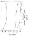
- Fig. 4 depicts the cell performance for a cell with applied current 20mA/cm 2 and having a Flemion membrane. Applied current (mA/cm 2 ) 20 30 40 Coulombic efficiency (%) 95 95 96 Voltage efficiency (%) 81 68 64 Energy efficiency (%) 77 64.5 61.4
- Stabilising agents and their effect are described in Table 1. Investigation of the stabilizing agents in 2M V(V) solution Stabilising agent Percentage used Effect Thiourea H 2 NCSHN 2 0.1 - 20% (by wt./vol.) Complexed by reducing Ammonium oxalate (NH4) 2 C 2 O 4 .H 2 O 1 - 30% (by wt./vol.) Slightly reducing Glycerine C 3 H 8 O 3 0.1 - 20% Complexed by reducing Diphenyl-thiocarbazone C 13 H 12 SN 4 0.01 - 1 % (by wt./vol.) Form solid product Tri-n-butyl phosphate [CH 3 (CH 2 ) 3 PO 4 1 - 5% Form solid product EDTA disodium salt [CH 2 .(CH 2 COOH).CH 2 COO Na] 2 .2H 2 O 0.5 - 5% Reducing and form solid product solid product Tri-sodium citrate Na 3 C 6 H 5 O 7
- the specified amount of additive was added to the V 2 O 5 powder and H 2 SO 4 suspension in the negative half of an electrolysis cell and a constant current of 20 mA/M 2 applied for the appropriate time required to reduce the V(V) to V(III.5+) V III /V IV state. This solution was then used in a redox cell to prepare each oxidant state. Comparison of the production of electrolyte of higher concentration from V 2 O 5 and NH 4 VO 3 in water and sulphuric acid with and without the presence of stabilising agent.
- the potentiometric method of electroanalytical chemistry is used for the determination of total vanadium concentration of the electrolyte of the vanadium redox cell.
- concentration of vanadium ions can also be readily determined by using Inductively Coupled Plasma Emission Spectrometry (ICPES), but has proven to be more complex and is suitable only for a very dilute solution due to low sensitivity range and may introduce sufficient errors that the analysis of the solution at higher concentration can be impeded.
- ICPES Inductively Coupled Plasma Emission Spectrometry
- V(V) is the most complicated species of the electrolyte of vanadium redox cell. In ambient conditions and low temperature it is quite stable, but with increasing temperatures it has the tendency to precipitate very rapidly.
- the results obtained from the stability test of V(II) solutions with stabilising agents at ambient conditions are significantly higher as compared with the solutions without stabilising agent.
- the initial V(II) solution concentration was 2.07M, after 10 days it was 1.68M and after 40 days, 1.42M vanadium concentration was found. However with 1% glycerine as a stabilising agent the initial V(II) concentration was 2.82M. After 10 days it was 2.00M and after 40 days it was stable in 1.86M.
- V(III) solution containing 2.46M vanadium concentration was found to be 2.30M after 10 days and it was stable at 2.23M after 40 days whereas the V(III) solution containing 1% glycerine had the initial concentration of 3.21M, which became 2.96M after 10 days and stable at 2.43M after 40 days.
- the electrolyte was prepared by a method in which the V 2 O 5 electrolysis process was separated into two different steps.
- the solution electrolysis step involved the electrolytic reduction of a solution of vanadium ions to a 100% V 3+ oxidation state.
- V 2 O 5 is induced to dissolve in the V 3+ solution by the V 3+ ions which acts as a leaching agent for the V 2 O 5 .
- a 5.1M vanadium solution was prepared by taking 200ml of 1.87M V 3+ solution in about 3M sulphuric acid and adding 35g of V 2 O 5 powder plus 0.6g of D-fructose. The powder dissolved after about 10 minutes and the resulting solution was 3.3M V(IV) in 5.35M sulphate. This solution was then placed in an electrolysis cell and reduced to V 3.5+ . A 160ml portion of the V 3.5+ solution, 48g of V 2 O 5 powder and 0.1g of D-fructose was mixed by mechanical stirring. The dissolution reaction again proceeded quickly (within about 10 min) and after reaction the mixture was taken and filtered.
- the filtered solution was titrated with 0.2M KMnO 4 and the resulting concentration of vanadium obtained was 5.1M.
- the oxidation state of the solution obtained was close to 100% V 4+ with a sulphate concentration of 5.35M.
- the 5.1M V(IV) electrolyte was then placed into both the positive and negative compartments of a small redox battery with an ionically conducting separator therebetween and charged up to the V 2+ and V(V) states in the positive and negative half cells respectively using a current of approximately 10 mA/cm 2 .
- the battery was discharged at various current densities and the resultant cell voltage vs time curves as shown in Figure 22.
- a 7.1M vanadium solution was prepared by taking 400ml of 1.87M V 3+ solution in about 3M sulphuric acid and adding 68g of V 2 O 5 powder plus 44ml of 18M H 2 SO 4 . To this was added 6.9g of D-fructose which was 1 % w/w. The powder was stirred until fully dissolved and the final solution was 3.4M V(IV). From this solution a volume of 350ml was placed in the negative compartment of an electrolysis cell and reduced to V 3+ . To this solution 120g of V 2 O 5 powder was added and 1.2g of D-fructose was also added to produce a final V(II) solution containing 1%w/w D-fructose. The concentration of the final solution was determined as 7.1M V 4+ . This solution was stable at room temperature for 6 days before a slight precipitate started to appear.
Claims (18)
- All-Vanadium-Redoxzelle mit einer Elektrolytlösung, die Vanadium-Redoxionen und einen Elektrolyten umfasst, wobei die Konzentration der Vanadium-Redoxionen 1 M bis 10 M beträgt, dadurch gekennzeichnet, dass die Elektrolytlösung weiterhin ein Stabilisierungsmittel umfasst, das aus der Gruppe ausgewählt ist, die aus Ammoniumoxalat, Glycerin, Natriumgluconat, Galactose, Galaktit, γ-Lacton (und Na- und K-Salz), Idose, Idonsäure (und Na- und K-Salz), Idit, Mannose, Mannit, Mannonsäure (und Na- und K-Salz), Sorbit, Inosit, Fructose, Fucose, Triethylentetramin oder Gemischen aus zwei oder mehreren derselben besteht, wobei das Stabilisierungsmittel in einer Konzentration von 0,05 bis 20 Mol-% Stabilisierungsmittel zu Vanadium-Redoxionen vorhanden ist und wobei das Ausfallen von Vanadiumspezies aus der Elektrolytlösung durch das Stabilisierungsmittel verhindert oder reduziert wird, wenn ansonsten ein Ausfallen der Vanadiumspezies stattfinden würde.
- All-Vanadium-Redoxzelle gemäß Anspruch 1, wobei wenigstens eine Elektrolytlösung eine wässrige Lösung ist und die Vanadium-Redoxionen in einem Bereich vorhanden sind, der aus der Gruppe ausgewählt ist, die aus 1,5 M bis 8 M oder 2 M bis 10 M besteht.
- All-Vanadium-Redoxzelle gemäß Anspruch 1, wobei die wenigstens eine Elektrolytlösung eine wässrige Lösung ist und die Vanadium-Redoxionen in einer übersättigten Konzentration vorhanden sind.
- All-Vanadium-Redoxzelle gemäß einem der Ansprüche 1 bis 3, wobei die Elektrolytlösung eine wässrige Lösung ist und der Elektrolyt aus der Gruppe ausgewählt ist, die aus H2SO4, Trifluormethansulfonsäure, Na2SO4, K2SO4, H3PO4, Na3PO4, K3PO4, KNO3, NaNO3, Sulfonsäure, C6-C14-Arylsulfonsäure, wie p-Toluolsulfonsäure, Benzolsulfonsäure, Naphthalinsulfonsäure, C1-C6-Alkylsulfonsäure, wie Methylsulfonsäure und Ethylsulfonsäure, Essigsäure und Gemischen davon besteht.
- All-Vanadium-Redoxzelle gemäß Anspruch 4, wobei es sich bei dem Elektrolyten um H2SO4 handelt.
- All-Vanadium-Redoxzelle gemäß Anspruch 5, wobei die H2SO4 in einem Konzentrationsbereich von 4 M bis 6,5 M vorhanden ist.
- All-Vanadium-Redoxzelle gemäß Anspruch 1, wobei die Redoxionen aus der Gruppe ausgewählt sind, die aus fünfwertigen Vanadiumionen, vierwertigen Vanadiumionen, dreiwertigen Vanadiumionen, zweiwertigen Vanadiumionen, einem Gemisch von zweiwertigen und dreiwertigen Vanadiumionen, einem Gemisch von zweiwertigen und vierwertigen Vanadiumionen, einem Gemisch von dreiwertigen und vierwertigen Vanadiumionen, einem Gemisch von zweiwertigen, dreiwertigen und vierwertigen Vanadiumionen, einem Gemisch von zweiwertigen, dreiwertigen, vierwertigen und fünfwertigen Vanadiumianen sowie einem Gemisch von vierwertigen und fünfwerttgen Vanadiumionen besteht.
- All-Vanadium-Redoxzelle gemäß einem der Ansprüche 1 bis 7, wobei das Stabilisierungsmittel in einem Bereich vorhanden ist, der aus der Gruppe ausgewählt ist, die aus 0,1 bis 10 Mol-%, 0,5 bis 8 Mol-% und 0,5 bis 5 Mol-% Stabilisierungsmittel zu Vanadiumionen besteht.
- All-Vanadium-Redoxzelle gemäß Anspruch 8, wobei das Stabilisierungsmittel in einem Bereich von 0,5 bis 5 Mol-% Stabilisierungsmittel zu Vanadiumionen vorhanden ist.
- All-Vanadium-Redoxzelle gemäß Anspruch 1, wobei die positive Elektrode aus der Gruppe ausgewählt ist, die aus einer oxidierendes-Gas-Elektrode, einer Sauerstoffelektrode und einer Luftelektrode besteht, wobei die positive Elektrode einen Gaskontaktteil hat, wobei der Gaskontaktteil so angeordnet ist, dass er mit einem Gas in Kontakt treten kann, das aus der Gruppe ausgewählt ist, die aus einem oxidierenden Gas, Sauerstoff, einem sauerstoffhaltigen Gas und Luft besteht.
- All-Vanadium-Redoxzelle gemäß Anspruch 1, wobei die negative Elektrode aus der Gruppe ausgewählt ist, die aus einer reduzierendes-Gas-Elektrode und einer Wasserstoffgaselektrode besteht, und die negative Elektrode einen Gaskontaktteil hat, wobei der Gaskontaktteil so angeordnet ist, dass er mit einem Gas in Kontakt treten kann, das aus der Gruppe ausgewählt ist, die aus einem reduzierenden Gas, einem wasserstoffhaltigen Gas und Wasserstoff besteht.
- All-Vanadium-Redoxzelle gemäß einem der Ansprüche 1 bis 11 mit einem positiven Kompartiment, das einen Katholyten In elektrischem Kontakt mit einer positiven Elektrode enthält, wobei der Katholyt einen Elektrolyten umfasst, der Vanadium-Redoxionen enthält, die aus der Gruppe ausgewählt sind, die aus dreiwertigen Vanadiumionen, vierwertigen Vanadiumionen, fünfwertigen Vanadiumionen sowie einem Gemisch von wenigstens zwei der Spezies dreiwertige Vanadiumionen, vierwertige Vanadiumionen und funfwertige Vanadiumionen besteht, einem negativen Kompartiment, das einen Anolyten in elektrischem Kontakt mit einer negativen Elektrode enthält, wobei der Anolyt einen Elektrolyten umfasst, der Vanadium-Redoxionen enthält, die aus der Gruppe ausgewählt sind, die aus vierwertigen Vanadiumionen, dreiwertigen Vanadiumionen, zweiwertigen Vanadiumionen sowie einem Gemisch von wenigstens zwei der Spezies zweiwertige Vanadiumionen, dreiwertige Vanadiumionen und vierwertige Vanadiumionen besteht, und einem Separator oder einer Membran, der bzw. die sich zwischen dem positiven und dem negativen Kompartiment befindet und mit dem Katholyten und dem Anolyten In Kontakt steht, so dass man eine ionische Verbindung dazwischen erhält.
- All-Vanadium-Redoxzelle gemäß Anspruch 12, wobei die Vanadiumionen im Anolyten und Katholyten in einer übersättigten Konzentration stabilisiert sind.
- All-Vanadium-Redoxzelle gemäß Anspruch 12, wobei der Katholyt das Stabilisierungsmittel enthält.
- All-Vanadium-Redoxzelle gemäß Anspruch 12, wobei der Anolyt das Stabilisierungsmittel enthält.
- All-Vanadium-Redoxzelle gemäß Anspruch 12, wobei der Anolyt und der Katholyt das Stabilisierungsmittel enthalten,
- Verfahren zum Wiederaufladen einer All-Vanadium-Redoxzelle gemäß einem der Ansprüche 1 bis 16, wobei die Zelle entladen oder partiell entladen ist, wobei das Verfahren das Versorgen der positiven und der negativen Elektrode mit elektrischer Energie umfasst, was zu reduzierten Vanadiumionen im Anolyten und oxidierten Vanadiumionen im Katholyten führt.
- Verfahren zur Herstellung von Elektrizität aus einer All-Vanadium-Redoxzelle gemäß einem der Ansprüche 1 bis 16, wenn die Zelle aufgeladen oder partiell aufgeladen ist, wobei das Verfahren das Entnehmen von elektrischer Energie aus der Redoxzelle umfasst, indem man einen äußeren Stromkreis in elektronische Verbindung mit der positiven und der negativen Elektrode bringt.
Applications Claiming Priority (7)
| Application Number | Priority Date | Filing Date | Title |
|---|---|---|---|
| AUPM2477/93 | 1993-11-17 | ||
| AUPM247793 | 1993-11-17 | ||
| AUPM247793 | 1993-11-17 | ||
| AUPM8716/94 | 1994-10-11 | ||
| AUPM871694 | 1994-10-11 | ||
| AUPM8716A AUPM871694A0 (en) | 1994-10-11 | 1994-10-11 | Stabilised electrolyte |
| PCT/AU1994/000711 WO1995012219A1 (en) | 1993-11-17 | 1994-11-17 | Stabilised electrolyte solutions, methods of preparation thereof and redox cells and batteries containing stabilised electrolyte solutions |
Related Child Applications (1)
| Application Number | Title | Priority Date | Filing Date |
|---|---|---|---|
| EP01105560 Division | 2001-03-06 |
Publications (3)
| Publication Number | Publication Date |
|---|---|
| EP0729648A1 EP0729648A1 (de) | 1996-09-04 |
| EP0729648A4 EP0729648A4 (de) | 1997-01-02 |
| EP0729648B1 true EP0729648B1 (de) | 2003-04-02 |
Family
ID=25644578
Family Applications (1)
| Application Number | Title | Priority Date | Filing Date |
|---|---|---|---|
| EP95900573A Expired - Lifetime EP0729648B1 (de) | 1993-11-17 | 1994-11-17 | Stabilisierte elektrolytlösungen, verfahren und deren herstellung und redoxzellen und batterien, die diese lösungen enthalten |
Country Status (8)
| Country | Link |
|---|---|
| US (2) | US6143443A (de) |
| EP (1) | EP0729648B1 (de) |
| JP (1) | JPH09507950A (de) |
| AT (1) | ATE236460T1 (de) |
| AU (1) | AU696452B2 (de) |
| DE (1) | DE69432428D1 (de) |
| MY (2) | MY113980A (de) |
| WO (1) | WO1995012219A1 (de) |
Cited By (5)
| Publication number | Priority date | Publication date | Assignee | Title |
|---|---|---|---|---|
| DE102007011311A1 (de) * | 2006-12-22 | 2008-06-26 | Mtu Cfc Solutions Gmbh | Vanadium-Redox-Batterie und Verfahren zu ihrem Betrieb |
| DE102008030343A1 (de) * | 2008-06-26 | 2009-12-31 | Siemens Aktiengesellschaft | Spurgeführtes Fahrzeug |
| DE102009009357A1 (de) * | 2009-02-18 | 2010-09-02 | Fraunhofer-Gesellschaft zur Förderung der angewandten Forschung e.V. | Methode zur Speicherung von elektrischer Energie in ionischen Flüssigkeiten |
| CN104900892A (zh) * | 2014-03-03 | 2015-09-09 | 大连融科储能技术发展有限公司 | 液流电池负极电解液密封系统及液流电池系统 |
| US10673090B2 (en) | 2014-10-06 | 2020-06-02 | Battelle Memorial Institute | All-vanadium sulfate acid redox flow battery system |
Families Citing this family (164)
| Publication number | Priority date | Publication date | Assignee | Title |
|---|---|---|---|---|
| CA2220075C (en) * | 1995-05-03 | 2008-07-08 | Unisearch Limited | High energy density vanadium electrolyte solutions, methods of preparation thereof and all-vanadium redox cells and batteries containing high energy vanadium electrolyte solutions |
| EP1036037B1 (de) * | 1997-12-04 | 2004-02-25 | Steris Corporation | Chemische änderung von elektrochemisch aktiviertem wasser |
| JP3959234B2 (ja) * | 2000-12-26 | 2007-08-15 | 日本化学工業株式会社 | 変性バナジウム化合物、その製造方法、レドックスフロー型電池用電解液組成物及びレドックスフロー型電池用電解液の製造方法 |
| JP3897544B2 (ja) | 2001-06-07 | 2007-03-28 | 住友電気工業株式会社 | レドックスフロー電池用電解液およびレドックスフロー電池 |
| US7625663B2 (en) * | 2001-08-10 | 2009-12-01 | Plurion Limited Company | Cerium batteries |
| US20060063065A1 (en) * | 2001-08-10 | 2006-03-23 | Clarke Robert L | Battery with bifunctional electrolyte |
| WO2003017407A1 (en) * | 2001-08-10 | 2003-02-27 | Eda, Inc. | Improved load leveling battery and methods therefor |
| AUPR722101A0 (en) * | 2001-08-24 | 2001-09-13 | Skyllas-Kazacos, Maria | Vanadium chloride/polyhalide redox flow battery |
| US6921593B2 (en) | 2001-09-28 | 2005-07-26 | Hewlett-Packard Development Company, L.P. | Fuel additives for fuel cell |
| KR100660483B1 (ko) * | 2002-04-15 | 2006-12-22 | 히다치 막셀 가부시키가이샤 | 이온전도성 전해질 및 그것을 사용한 전지 |
| AUPS192102A0 (en) * | 2002-04-23 | 2002-05-30 | Unisearch Limited | Vanadium bromide redox flow battery |
| US6700298B1 (en) * | 2002-06-27 | 2004-03-02 | The United States Of America As Represented By The Administrator Of The National Aeronautics And Space Administration | Extremely-efficient, miniaturized, long-lived alpha-voltaic power source using liquid gallium |
| AU2003901763A0 (en) * | 2003-04-14 | 2003-05-01 | Michael Kazacos | Novel bromide redox flow cells and batteries |
| KR100515332B1 (ko) * | 2003-04-28 | 2005-09-15 | 삼성에스디아이 주식회사 | 리튬 전지용 전해질 및 이를 포함하는 리튬 전지 |
| CN1304640C (zh) * | 2003-09-18 | 2007-03-14 | 攀枝花钢铁有限责任公司钢铁研究院 | 全钒离子液流电池电解液的电解制备方法 |
| US7353083B2 (en) | 2004-01-15 | 2008-04-01 | Vrb Power Systems Inc. | Vanadium redox battery energy storage and power generation system incorporating and optimizing diesel engine generators |
| US7265456B2 (en) | 2004-01-15 | 2007-09-04 | Vrb Bower Systems Inc. | Power generation system incorporating a vanadium redox battery and a direct current wind turbine generator |
| US8277964B2 (en) | 2004-01-15 | 2012-10-02 | Jd Holding Inc. | System and method for optimizing efficiency and power output from a vanadium redox battery energy storage system |
| US7227275B2 (en) * | 2005-02-01 | 2007-06-05 | Vrb Power Systems Inc. | Method for retrofitting wind turbine farms |
| CN100438190C (zh) * | 2005-03-29 | 2008-11-26 | 攀钢集团攀枝花钢铁研究院 | 全钒离子液流电池电解液及其制备方法 |
| JP5760262B2 (ja) * | 2005-06-20 | 2015-08-05 | ニューサウス イノヴェーションズ ピーティーワイ リミテッド | レドックスセルおよび電池の改良されたパーフルオロ膜および改良された電解質 |
| US20070072067A1 (en) * | 2005-09-23 | 2007-03-29 | Vrb Power Systems Inc. | Vanadium redox battery cell stack |
| US7923965B2 (en) | 2005-10-10 | 2011-04-12 | General Electric Company | Methods for coupling an energy storage system to a variable energy supply system |
| US7181183B1 (en) * | 2006-01-27 | 2007-02-20 | Vrb Power Systems Inc. | Telecommunication system incorporating a vanadium redox battery energy storage system |
| AT503315B1 (de) * | 2006-03-06 | 2008-02-15 | Funktionswerkstoffe Forschungs | Redox-durchfluss-batterie, sowie elektrolyt-lösung für eine redox-durchfluss-batterie |
| US20100059388A1 (en) * | 2006-05-05 | 2010-03-11 | Aic Nevada, Inc. | Electrochemical Oxidation of Organic Matter |
| CN100490033C (zh) * | 2006-06-05 | 2009-05-20 | 厦门大学 | 基于液相中的电化学活性物质的超级电容器 |
| US7855005B2 (en) * | 2007-02-12 | 2010-12-21 | Deeya Energy, Inc. | Apparatus and methods of determination of state of charge in a redox flow battery |
| US20080218941A1 (en) * | 2007-03-07 | 2008-09-11 | Julius Regalado | Multifunctional power storage device |
| US7517608B2 (en) * | 2007-03-09 | 2009-04-14 | Vrb Power Systems Inc. | Inherently safe redox flow battery storage system |
| US7687193B2 (en) | 2007-08-17 | 2010-03-30 | Jd Holding Inc. | Electrochemical battery incorporating internal manifolds |
| US8587150B2 (en) * | 2008-02-28 | 2013-11-19 | Deeya Energy, Inc. | Method and modular system for charging a battery |
| TW201008118A (en) | 2008-04-10 | 2010-02-16 | Atmel Corp | Capacitive touch screen with noise suppression |
| US20090265252A1 (en) * | 2008-04-21 | 2009-10-22 | Charles Dale Fletcher | Money pooling with electronic invoice |
| US9786944B2 (en) * | 2008-06-12 | 2017-10-10 | Massachusetts Institute Of Technology | High energy density redox flow device |
| US11909077B2 (en) | 2008-06-12 | 2024-02-20 | Massachusetts Institute Of Technology | High energy density redox flow device |
| US8722226B2 (en) | 2008-06-12 | 2014-05-13 | 24M Technologies, Inc. | High energy density redox flow device |
| JP5627576B2 (ja) | 2008-06-16 | 2014-11-19 | ポリプラス バッテリー カンパニーPolyPlus Battery Company | 水性リチウム−空気バッテリセル |
| US7927731B2 (en) * | 2008-07-01 | 2011-04-19 | Deeya Energy, Inc. | Redox flow cell |
| US8785023B2 (en) | 2008-07-07 | 2014-07-22 | Enervault Corparation | Cascade redox flow battery systems |
| US7820321B2 (en) | 2008-07-07 | 2010-10-26 | Enervault Corporation | Redox flow battery system for distributed energy storage |
| US7919204B2 (en) * | 2008-10-10 | 2011-04-05 | Deeya Energy, Inc. | Thermal control of a flow cell battery |
| WO2010042899A1 (en) * | 2008-10-10 | 2010-04-15 | Deeya Energy Technology, Inc. | Flexible multi-walled tubing assembly |
| US20100092843A1 (en) * | 2008-10-10 | 2010-04-15 | Deeya Energy Technologies, Inc. | Venturi pumping system in a hydrogen gas circulation of a flow battery |
| WO2010042900A1 (en) * | 2008-10-10 | 2010-04-15 | Deeya Energy Technologies, Inc. | Methods for bonding porous flexible membranes using solvent |
| US8230736B2 (en) * | 2008-10-10 | 2012-07-31 | Deeya Energy, Inc. | Level sensor for conductive liquids |
| CN102246385B (zh) * | 2008-10-10 | 2015-07-29 | 艾默吉电力系统股份有限公司 | 用于确定电池的荷电状态的方法和设备 |
| KR102046773B1 (ko) | 2009-04-06 | 2019-11-20 | 24엠 테크놀러지스 인코퍼레이티드 | 산화환원 흐름 배터리를 사용하는 연료 시스템 |
| WO2010138948A2 (en) * | 2009-05-28 | 2010-12-02 | Deeya Energy, Inc. | Buck-boost control circuit |
| CN102844925B (zh) * | 2009-05-28 | 2015-11-25 | 艾默吉电力系统股份有限公司 | 电解质组合物 |
| US8587255B2 (en) * | 2009-05-28 | 2013-11-19 | Deeya Energy, Inc. | Control system for a flow cell battery |
| WO2010138942A2 (en) * | 2009-05-28 | 2010-12-02 | Deeya Energy, Inc. | Redox flow cell rebalancing |
| US8349477B2 (en) * | 2009-05-28 | 2013-01-08 | Deeya Energy, Inc. | Optical leak detection sensor |
| US8394529B2 (en) * | 2009-05-28 | 2013-03-12 | Deeya Energy, Inc. | Preparation of flow cell battery electrolytes from raw materials |
| US8551299B2 (en) * | 2009-05-29 | 2013-10-08 | Deeya Energy, Inc. | Methods of producing hydrochloric acid from hydrogen gas and chlorine gas |
| CN101989660B (zh) * | 2009-08-03 | 2012-10-31 | 夏嘉琪 | 全钒液流储能电池封闭式电解液储液罐的排气系统 |
| TWI383534B (zh) * | 2009-10-28 | 2013-01-21 | Yung Han Huang | 恆久性電池 |
| KR101139788B1 (ko) * | 2010-02-10 | 2012-04-26 | 한국과학기술연구원 | Sn 또는 Ce 이온이 첨가된 용해 납 레독스 흐름 배터리용 전해액 및 이를 포함하는 전지 |
| US8951665B2 (en) * | 2010-03-10 | 2015-02-10 | Imergy Power Systems, Inc. | Methods for the preparation of electrolytes for chromium-iron redox flow batteries |
| WO2011136256A1 (ja) * | 2010-04-27 | 2011-11-03 | 住友電気工業株式会社 | レドックスフロー電池 |
| WO2011140322A1 (en) * | 2010-05-05 | 2011-11-10 | Benham Roger A | Pressure density differential device |
| US10651492B2 (en) | 2010-06-22 | 2020-05-12 | Vrb Energy Inc. | Integrated system for electrochemical energy storage system |
| US9281535B2 (en) | 2010-08-12 | 2016-03-08 | Imergy Power Systems, Inc. | System dongle |
| US9960443B2 (en) | 2010-09-28 | 2018-05-01 | Battelle Memorial Institute | Redox flow batteries having multiple electroactive elements |
| US8628880B2 (en) | 2010-09-28 | 2014-01-14 | Battelle Memorial Institute | Redox flow batteries based on supporting solutions containing chloride |
| US8771856B2 (en) | 2010-09-28 | 2014-07-08 | Battelle Memorial Institute | Fe-V redox flow batteries |
| KR101747862B1 (ko) | 2010-11-03 | 2017-06-16 | 삼성전자주식회사 | 레독스 플로우 전지 |
| US8709629B2 (en) | 2010-12-22 | 2014-04-29 | Jd Holding Inc. | Systems and methods for redox flow battery scalable modular reactant storage |
| CN103339762B (zh) | 2011-01-13 | 2016-03-30 | 伊莫基动力系统公司 | 液流电池单元堆 |
| US8980484B2 (en) | 2011-03-29 | 2015-03-17 | Enervault Corporation | Monitoring electrolyte concentrations in redox flow battery systems |
| US8916281B2 (en) | 2011-03-29 | 2014-12-23 | Enervault Corporation | Rebalancing electrolytes in redox flow battery systems |
| US9083019B2 (en) * | 2011-06-14 | 2015-07-14 | United Technologies Corporation | System and method for operating a flow battery system at an elevated temperature |
| KR20130015228A (ko) * | 2011-08-02 | 2013-02-13 | 삼성에스디아이 주식회사 | 레독스 플로우 전지용 격리막 및 이를 포함하는 레독스 플로우 전지 |
| CN102306820A (zh) * | 2011-08-08 | 2012-01-04 | 中南大学 | 一种钒电池用电解液及其制备方法 |
| WO2013028574A2 (en) * | 2011-08-19 | 2013-02-28 | Polyplus Battery Company | Aqueous lithium air batteries |
| US10141594B2 (en) | 2011-10-07 | 2018-11-27 | Vrb Energy Inc. | Systems and methods for assembling redox flow battery reactor cells |
| US20130095362A1 (en) * | 2011-10-14 | 2013-04-18 | Deeya Energy, Inc. | Vanadium flow cell |
| US9853454B2 (en) | 2011-12-20 | 2017-12-26 | Jd Holding Inc. | Vanadium redox battery energy storage system |
| KR101684036B1 (ko) * | 2011-12-28 | 2016-12-07 | 아사히 가세이 가부시키가이샤 | 레독스 플로우 2차 전지 및 레독스 플로우 2차 전지용 전해질막 |
| AT512184B1 (de) * | 2012-01-23 | 2013-06-15 | Cellstrom Gmbh | System zur energieerzeugung bzw. -speicherung auf elektrochemischer basis |
| KR101968639B1 (ko) * | 2012-01-31 | 2019-04-12 | 삼성전자주식회사 | 유기 전해액 및 이를 포함하는 레독스 플로우 전지 |
| US20130252062A1 (en) * | 2012-03-20 | 2013-09-26 | Zinc Air, Inc. | Secondary redox flow battery and method of making same |
| KR101415538B1 (ko) * | 2012-03-23 | 2014-07-04 | 세하특허 주식회사 | 전기분해를 이용한 vrb 용 전해액 제조장치 및 제조방법 |
| US9214695B2 (en) * | 2012-04-04 | 2015-12-15 | Battelle Memorial Institute | Hybrid anodes for redox flow batteries |
| US9484569B2 (en) | 2012-06-13 | 2016-11-01 | 24M Technologies, Inc. | Electrochemical slurry compositions and methods for preparing the same |
| CN103515641B (zh) * | 2012-06-18 | 2016-04-13 | 攀钢集团攀枝花钢铁研究院有限公司 | 一种三价钒离子电解液及其制备方法和一种钒电池 |
| US9768463B2 (en) | 2012-07-27 | 2017-09-19 | Lockheed Martin Advanced Energy Storage, Llc | Aqueous redox flow batteries comprising metal ligand coordination compounds |
| IN2015DN00676A (de) * | 2012-07-27 | 2015-06-26 | Lockheed Martin Advanced Energy Storage Llc | |
| US10164284B2 (en) | 2012-07-27 | 2018-12-25 | Lockheed Martin Energy, Llc | Aqueous redox flow batteries featuring improved cell design characteristics |
| US8753761B2 (en) * | 2012-07-27 | 2014-06-17 | Sun Catalytix Corporation | Aqueous redox flow batteries comprising metal ligand coordination compounds |
| US9559374B2 (en) | 2012-07-27 | 2017-01-31 | Lockheed Martin Advanced Energy Storage, Llc | Electrochemical energy storage systems and methods featuring large negative half-cell potentials |
| US9865893B2 (en) | 2012-07-27 | 2018-01-09 | Lockheed Martin Advanced Energy Storage, Llc | Electrochemical energy storage systems and methods featuring optimal membrane systems |
| US9382274B2 (en) | 2012-07-27 | 2016-07-05 | Lockheed Martin Advanced Energy Storage, Llc | Aqueous redox flow batteries featuring improved cell design characteristics |
| US9899694B2 (en) | 2012-07-27 | 2018-02-20 | Lockheed Martin Advanced Energy Storage, Llc | Electrochemical energy storage systems and methods featuring high open circuit potential |
| MX2020001174A (es) * | 2012-08-15 | 2021-08-12 | Lockheed Martin Energy Llc | Hexacianuros de hierro de alta solubilidad. |
| US9685651B2 (en) | 2012-09-05 | 2017-06-20 | Ess Tech, Inc. | Internally manifolded flow cell for an all-iron hybrid flow battery |
| WO2014039731A1 (en) | 2012-09-05 | 2014-03-13 | Energy Storage Systems, Inc. | Redox and plating electrode systems for an all-iron hybrid flow battery |
| JP5770239B2 (ja) * | 2012-09-28 | 2015-08-26 | アマゾン電池株式会社 | バナジウムリン酸錯体二次電池 |
| US9362583B2 (en) | 2012-12-13 | 2016-06-07 | 24M Technologies, Inc. | Semi-solid electrodes having high rate capability |
| US8993159B2 (en) | 2012-12-13 | 2015-03-31 | 24M Technologies, Inc. | Semi-solid electrodes having high rate capability |
| CN104756298B (zh) * | 2012-12-25 | 2017-02-22 | 日新电机株式会社 | 蓄电池 |
| US8993183B2 (en) | 2012-12-31 | 2015-03-31 | Enervault Corporation | Operating a redox flow battery with a negative electrolyte imbalance |
| EP2754732B1 (de) * | 2013-01-15 | 2015-03-11 | ATOTECH Deutschland GmbH | Wässrige Zusammensetzung zur Ätzung von Kupfer und Kupferlegierungen |
| ES2602077T3 (es) | 2013-02-26 | 2017-02-17 | Fundació Institut De Recerca En Energia De Catalunya | Formulaciones de electrolito para utilizar en baterías redox de flujo |
| US8980454B2 (en) | 2013-03-15 | 2015-03-17 | Enervault Corporation | Systems and methods for rebalancing redox flow battery electrolytes |
| US9882238B2 (en) | 2013-05-16 | 2018-01-30 | Nanotek Instruments, Inc. | Lithium-sulfur secondary battery containing gradient electrolyte |
| JP6204069B2 (ja) * | 2013-05-23 | 2017-09-27 | 旭化成株式会社 | 電解液及びレドックスフロー電池 |
| JP6180189B2 (ja) * | 2013-05-23 | 2017-08-16 | 旭化成株式会社 | 電解液組成物及びレドックスフロー電池 |
| JP5988268B2 (ja) * | 2013-05-31 | 2016-09-07 | 株式会社 東北テクノアーチ | バナジウム固体塩電池 |
| US9905860B2 (en) | 2013-06-28 | 2018-02-27 | Polyplus Battery Company | Water activated battery system having enhanced start-up behavior |
| WO2014207923A1 (ja) * | 2013-06-28 | 2014-12-31 | 日新電機 株式会社 | レドックスフロー電池 |
| US9601803B2 (en) * | 2013-07-22 | 2017-03-21 | Nanotek Instruments, Inc. | Non-flammable quasi-solid electrolyte-separator layer product for lithium battery applications |
| US9601805B2 (en) * | 2013-07-22 | 2017-03-21 | Nanotek Instruments, Inc. | Process for producing non-flammable quasi-solid electrolyte and electrolyte-separator for lithium battery applications |
| KR102134055B1 (ko) * | 2013-08-07 | 2020-07-14 | 스미토모덴키고교가부시키가이샤 | 레독스 플로우 전지 |
| US9846116B2 (en) * | 2014-04-21 | 2017-12-19 | Unienergy Technologies, Llc | Methods for determining and/or adjusting redox-active element concentrations in redox flow batteries |
| KR101653765B1 (ko) | 2014-05-26 | 2016-09-02 | 롯데케미칼 주식회사 | 레독스 흐름 전지용 양극 전해질 제조 방법 및 레독스 흐름 전지 |
| PT107816A (pt) | 2014-07-31 | 2016-02-01 | Inst Superior Técnico | Processo simplificado de preparação de eletrólito para pilha redox de vanádio |
| KR101698845B1 (ko) * | 2014-09-17 | 2017-01-24 | 한국에너지기술연구원 | 계면활성제를 포함하는 레독스 플로우 전지용 전해액 |
| SG10201902585QA (en) * | 2014-10-06 | 2019-04-29 | Eos Energy Storage Llc | Electrolyte for rechargeable electrochemical cell |
| CN104269572B (zh) * | 2014-10-13 | 2016-08-17 | 四川长虹电源有限责任公司 | 复合稳定剂优化的全钒氧化还原液流电池电解液的制备方法 |
| KR102512254B1 (ko) | 2014-11-26 | 2023-03-20 | 록히드 마틴 에너지, 엘엘씨 | 치환된 카테콜레이트의 금속 착물 및 이를 포함하는 레독스 플로우 배터리 |
| JP5860527B1 (ja) * | 2014-12-25 | 2016-02-16 | 株式会社ギャラキシー | バナジウム活物質液及びバナジウムレドックス電池 |
| KR101942904B1 (ko) * | 2015-01-07 | 2019-01-28 | 주식회사 엘지화학 | 플로우 배터리에 적용 가능한 전해액 혼합 모듈 및 이를 이용한 플로우 배터리의 전해액 혼합 방법 |
| US10253051B2 (en) | 2015-03-16 | 2019-04-09 | Lockheed Martin Energy, Llc | Preparation of titanium catecholate complexes in aqueous solution using titanium tetrachloride or titanium oxychloride |
| WO2016160028A1 (en) * | 2015-04-03 | 2016-10-06 | United Technologies Corporation | Method of treating liquid electrolyte solution |
| US9793566B2 (en) * | 2015-04-17 | 2017-10-17 | Battelle Memorial Institute | Aqueous electrolytes for redox flow battery systems |
| JP6639801B2 (ja) * | 2015-04-28 | 2020-02-05 | 株式会社クオルテック | 金属リン酸錯体二次電池 |
| US9899695B2 (en) * | 2015-05-22 | 2018-02-20 | General Electric Company | Zinc-based electrolyte compositions, and related electrochemical processes and articles |
| WO2016201230A1 (en) | 2015-06-10 | 2016-12-15 | Rhodia Operations | Phosphonated polysaccharides and gels and process for making same |
| KR101677107B1 (ko) * | 2015-08-24 | 2016-11-17 | 한국에너지기술연구원 | 레독스 흐름전지용 전해액 첨가제 및 이를 포함하는 레독스 흐름전지 |
| WO2017124098A1 (en) | 2016-01-15 | 2017-07-20 | 24M Technologies, Inc. | Systems and methods for infusion mixing a slurry-based electrode |
| KR101851376B1 (ko) * | 2016-02-02 | 2018-05-31 | 롯데케미칼 주식회사 | 레독스 흐름 전지용 전해액 및 레독스 흐름 전지 |
| WO2017142042A1 (ja) * | 2016-02-16 | 2017-08-24 | 京セラ株式会社 | フロー電池 |
| US10316047B2 (en) | 2016-03-03 | 2019-06-11 | Lockheed Martin Energy, Llc | Processes for forming coordination complexes containing monosulfonated catecholate ligands |
| US10644342B2 (en) | 2016-03-03 | 2020-05-05 | Lockheed Martin Energy, Llc | Coordination complexes containing monosulfonated catecholate ligands and methods for producing the same |
| KR101751987B1 (ko) | 2016-03-22 | 2017-07-07 | 유성훈 | 생산성이 향상된 레독스 흐름 전지용 전해액 제조장치 및 이를 이용한 레독스 흐름 전지용 전해액 제조방법 |
| US10892524B2 (en) | 2016-03-29 | 2021-01-12 | Eos Energy Storage, Llc | Electrolyte for rechargeable electrochemical cell |
| US9938308B2 (en) | 2016-04-07 | 2018-04-10 | Lockheed Martin Energy, Llc | Coordination compounds having redox non-innocent ligands and flow batteries containing the same |
| US10377687B2 (en) | 2016-07-26 | 2019-08-13 | Lockheed Martin Energy, Llc | Processes for forming titanium catechol complexes |
| JP6719728B2 (ja) * | 2016-07-26 | 2020-07-08 | 住友電気工業株式会社 | 電解液、電解槽用電解液、及び電解槽システム |
| US10343964B2 (en) | 2016-07-26 | 2019-07-09 | Lockheed Martin Energy, Llc | Processes for forming titanium catechol complexes |
| JP6765900B2 (ja) * | 2016-08-31 | 2020-10-07 | 京セラ株式会社 | フロー電池 |
| EP3291361B1 (de) * | 2016-09-02 | 2020-02-12 | Helmholtz-Zentrum Geesthacht Zentrum für Material- und Küstenforschung GmbH | Elektrolytadditive für magnesium-luft-batterien |
| KR102229442B1 (ko) | 2016-09-22 | 2021-03-17 | 주식회사 엘지화학 | 수계 레독스 플로우 전지용 유기계 양극 활물질 |
| WO2018067899A2 (en) | 2016-10-07 | 2018-04-12 | Vionx Energy Corporation | Electrochemical-based purification of electrolyte solutions, and related systems and methods |
| US10065977B2 (en) | 2016-10-19 | 2018-09-04 | Lockheed Martin Advanced Energy Storage, Llc | Concerted processes for forming 1,2,4-trihydroxybenzene from hydroquinone |
| CN106299435B (zh) * | 2016-11-11 | 2019-02-12 | 成都先进金属材料产业技术研究院有限公司 | 一种高稳定性的全钒液流电池电解液及其制备方法 |
| CN106384835B (zh) * | 2016-11-11 | 2019-01-22 | 攀钢集团攀枝花钢铁研究院有限公司 | 全钒液流电池电解液稳定剂及其制备方法 |
| US10930937B2 (en) | 2016-11-23 | 2021-02-23 | Lockheed Martin Energy, Llc | Flow batteries incorporating active materials containing doubly bridged aromatic groups |
| US10497958B2 (en) | 2016-12-14 | 2019-12-03 | Lockheed Martin Energy, Llc | Coordinatively unsaturated titanium catecholate complexes and processes associated therewith |
| US10741864B2 (en) | 2016-12-30 | 2020-08-11 | Lockheed Martin Energy, Llc | Aqueous methods for forming titanium catecholate complexes and associated compositions |
| US10320023B2 (en) | 2017-02-16 | 2019-06-11 | Lockheed Martin Energy, Llc | Neat methods for forming titanium catecholate complexes and associated compositions |
| JP2018170231A (ja) * | 2017-03-30 | 2018-11-01 | 京セラ株式会社 | フロー電池 |
| JP6668302B2 (ja) * | 2017-09-20 | 2020-03-18 | 株式会社東芝 | 二次電池、電池パック及び車両 |
| US20190264338A1 (en) * | 2018-02-27 | 2019-08-29 | California Institute Of Technology | Use of intermediates in solar fuels generation |
| WO2019200392A1 (en) * | 2018-04-13 | 2019-10-17 | Unienergy Technologies, Llc | Methods of preparing a vanadium electrolyte and mixtures therefor |
| CN110729504B (zh) * | 2018-07-17 | 2021-10-26 | 大连融科储能技术发展有限公司 | 降低液流电池电极氧化速度的方法及系统 |
| JP7000591B2 (ja) * | 2018-09-28 | 2022-01-19 | 京セラ株式会社 | 二次電池 |
| GB201902695D0 (en) * | 2019-02-28 | 2019-04-17 | Imperial Innovations Ltd | Redox flow cell |
| RU2716148C1 (ru) * | 2019-05-07 | 2020-03-06 | Открытое акционерное общество "Элеконд" | Способ приготовления электролита для ванадиевых редокс батарей |
| US20220333253A1 (en) * | 2021-04-08 | 2022-10-20 | Francois Cardarelli | Electrochemical preparation of vanadium electrolytes and sulfates of multivalent transition metals |
| CN113161614A (zh) * | 2021-05-19 | 2021-07-23 | 杭州华越新材料有限公司 | 一种锂离子电池电解液 |
| CN114142074B (zh) * | 2021-11-30 | 2023-10-27 | 成都先进金属材料产业技术研究院股份有限公司 | 提高钒电池电解液稳定性的方法 |
| DE102022128209B4 (de) | 2022-10-25 | 2024-05-02 | Fraunhofer-Gesellschaft zur Förderung der angewandten Forschung eingetragener Verein | Chlorid-freie Elektrolytzusammensetzung für einen längeren Betrieb bei hohen Temperaturen (>40°C) in Vanadium Redox-Flow-Batterien |
Family Cites Families (17)
| Publication number | Priority date | Publication date | Assignee | Title |
|---|---|---|---|---|
| US3279949A (en) * | 1961-07-27 | 1966-10-18 | Union Carbide Corp | Fuel cell half-cell containing vanadium redox couple |
| CH512827A (fr) * | 1969-02-10 | 1971-09-15 | Electrocell Ltd | Cellule électrochimique |
| GB1506560A (en) * | 1974-03-15 | 1978-04-05 | Ici Ltd | Device |
| JPS54138502A (en) * | 1978-04-17 | 1979-10-27 | Toyo Soda Mfg Co Ltd | Electrolytic reduction of organic and inorganic compounds |
| US4181777A (en) * | 1978-09-07 | 1980-01-01 | Diamond Shamrock Technologies S.A. | Rechargeable zinc halogen battery |
| JPS5834911B2 (ja) * | 1979-09-14 | 1983-07-29 | 工業技術院長 | レドツクス電池 |
| JPS5913154B2 (ja) * | 1980-06-17 | 1984-03-28 | 工業技術院長 | レドツクス電池 |
| JPS5913153B2 (ja) * | 1980-06-17 | 1984-03-28 | 工業技術院長 | レドツクス電池 |
| PL134200B1 (en) * | 1981-12-21 | 1985-07-31 | Polska Akademia Nauk Instytut Chemii Fizycznej | Electroactive material for supply sources |
| US4410606A (en) * | 1982-04-21 | 1983-10-18 | Loutfy Raouf O | Low temperature thermally regenerative electrochemical system |
| US4786567A (en) * | 1986-02-11 | 1988-11-22 | Unisearch Limited | All-vanadium redox battery |
| WO1989005363A1 (en) * | 1987-12-10 | 1989-06-15 | Unisearch Limited | Vanadium compound dissolution processes |
| WO1989005528A1 (en) * | 1987-12-10 | 1989-06-15 | Unisearch Limited | Vanadium charging cell and vanadium dual battery system |
| AU649272B2 (en) * | 1990-10-15 | 1994-05-19 | Director-General Of Agency Of Industrial Science And Technology | Method for producing vanadium electrolytic solution |
| US5318865A (en) * | 1991-06-06 | 1994-06-07 | Director-General, Agency Of Industrial Science And Technology | Redox battery |
| JPH05290871A (ja) * | 1992-04-09 | 1993-11-05 | Kashima Kita Kyodo Hatsuden Kk | バナジウム系電解液の製造方法 |
| US6143433A (en) * | 1994-09-14 | 2000-11-07 | Mitsui Chemicals, Inc. | Organic electroluminescent device and process for producing the same |
-
1994
- 1994-11-17 EP EP95900573A patent/EP0729648B1/de not_active Expired - Lifetime
- 1994-11-17 AU AU81366/94A patent/AU696452B2/en not_active Expired
- 1994-11-17 DE DE69432428T patent/DE69432428D1/de not_active Expired - Lifetime
- 1994-11-17 MY MYPI94003081A patent/MY113980A/en unknown
- 1994-11-17 US US08/649,612 patent/US6143443A/en not_active Expired - Lifetime
- 1994-11-17 AT AT95900573T patent/ATE236460T1/de not_active IP Right Cessation
- 1994-11-17 JP JP7510489A patent/JPH09507950A/ja not_active Ceased
- 1994-11-17 MY MYPI20015372A patent/MY125003A/en unknown
- 1994-11-17 WO PCT/AU1994/000711 patent/WO1995012219A1/en active IP Right Grant
-
2000
- 2000-07-24 US US09/624,317 patent/US6562514B1/en not_active Expired - Lifetime
Cited By (9)
| Publication number | Priority date | Publication date | Assignee | Title |
|---|---|---|---|---|
| DE102007011311A1 (de) * | 2006-12-22 | 2008-06-26 | Mtu Cfc Solutions Gmbh | Vanadium-Redox-Batterie und Verfahren zu ihrem Betrieb |
| DE102008030343A1 (de) * | 2008-06-26 | 2009-12-31 | Siemens Aktiengesellschaft | Spurgeführtes Fahrzeug |
| DE102009009357A1 (de) * | 2009-02-18 | 2010-09-02 | Fraunhofer-Gesellschaft zur Förderung der angewandten Forschung e.V. | Methode zur Speicherung von elektrischer Energie in ionischen Flüssigkeiten |
| DE102009009357B4 (de) * | 2009-02-18 | 2011-03-03 | Fraunhofer-Gesellschaft zur Förderung der angewandten Forschung e.V. | Redox-Flow-Batterie zur Speicherung von elektrischer Energie in ionischen Flüssigkeiten |
| US8802265B2 (en) | 2009-02-18 | 2014-08-12 | Fraunhofer-Gesellschaft Zur Forderung Der Angewandten Forschung E.V. | Method for storing electrical energy in ionic liquids |
| CN104900892A (zh) * | 2014-03-03 | 2015-09-09 | 大连融科储能技术发展有限公司 | 液流电池负极电解液密封系统及液流电池系统 |
| CN104900892B (zh) * | 2014-03-03 | 2017-10-17 | 大连融科储能技术发展有限公司 | 液流电池负极电解液密封系统及液流电池系统 |
| US10673090B2 (en) | 2014-10-06 | 2020-06-02 | Battelle Memorial Institute | All-vanadium sulfate acid redox flow battery system |
| US11532832B2 (en) | 2014-10-06 | 2022-12-20 | Battelle Memorial Institute | All-vanadium sulfate acid redox flow battery system |
Also Published As
| Publication number | Publication date |
|---|---|
| US6143443A (en) | 2000-11-07 |
| AU696452B2 (en) | 1998-09-10 |
| AU8136694A (en) | 1995-05-22 |
| JPH09507950A (ja) | 1997-08-12 |
| DE69432428D1 (de) | 2003-05-08 |
| MY113980A (en) | 2002-07-31 |
| ATE236460T1 (de) | 2003-04-15 |
| EP0729648A1 (de) | 1996-09-04 |
| WO1995012219A1 (en) | 1995-05-04 |
| MY125003A (en) | 2006-07-31 |
| US6562514B1 (en) | 2003-05-13 |
| EP0729648A4 (de) | 1997-01-02 |
Similar Documents
| Publication | Publication Date | Title |
|---|---|---|
| EP0729648B1 (de) | Stabilisierte elektrolytlösungen, verfahren und deren herstellung und redoxzellen und batterien, die diese lösungen enthalten | |
| US4786567A (en) | All-vanadium redox battery | |
| US7078123B2 (en) | High energy density vanadium electrolyte solutions, methods of preparation thereof and all-vanadium redox cells and batteries containing high energy vanadium electrolyte solutions | |
| US11208729B2 (en) | Methods and system for hydrogen production by water electrolysis | |
| Beck | The redox mechanism of the chelate-catalysed oxygen cathode | |
| US7320844B2 (en) | Vanadium/polyhalide redox flow battery | |
| AU728827B2 (en) | Electroconversion cell | |
| WO1989005363A1 (en) | Vanadium compound dissolution processes | |
| JP2994210B2 (ja) | バナジウム系レドックスフロー型電池の電解液 | |
| US5472807A (en) | Aluminum-ferricyanide battery | |
| US4370392A (en) | Chrome-halogen energy storage device and system | |
| JP2724817B2 (ja) | 全バナジウムのレドツクス電池 | |
| WO1989005528A1 (en) | Vanadium charging cell and vanadium dual battery system | |
| AU2002328660A1 (en) | Vanadium / polyhalide redox flow battery | |
| WO2003092138A2 (en) | Improved vanadium bromide battery (metal halide redox flow cell) | |
| CN102668224A (zh) | 钒电池 | |
| US10619257B2 (en) | Method of treating liquid electrolyte solution | |
| US20210079536A1 (en) | Electrochemical process for the production of pressurized gaseous hydrogen by electrolysis then by electrochemical conversion | |
| JP5713186B2 (ja) | レドックスフロー電池 | |
| Hu et al. | Redox‐active inorganic materials for redox flow batteries | |
| WO1989005526A1 (en) | All-vanadium redox battery and additives | |
| JPS61211960A (ja) | 二次電池 | |
| Minato et al. | Homogeneous catalytic reduction of polyoxometalate by hydrogen gas with a hydrogenase model complex | |
| RU2803292C1 (ru) | Способ получения электролита для ванадиевой проточной редокс-батареи | |
| AU704534B2 (en) | High energy density vanadium electrolyte solutions, methods of preparation thereof and all-vanadium redox cells and batteries containing high energy vanadium electrolyte solutions |
Legal Events
| Date | Code | Title | Description |
|---|---|---|---|
| PUAI | Public reference made under article 153(3) epc to a published international application that has entered the european phase |
Free format text: ORIGINAL CODE: 0009012 |
|
| 17P | Request for examination filed |
Effective date: 19960617 |
|
| AK | Designated contracting states |
Kind code of ref document: A1 Designated state(s): AT BE CH DE DK ES FR GB GR IE IT LI LU MC NL PT SE |
|
| AX | Request for extension of the european patent |
Free format text: LT PAYMENT 960617;SI PAYMENT 960617 |
|
| RAX | Requested extension states of the european patent have changed |
Free format text: LT PAYMENT 960617;SI PAYMENT 960617 |
|
| A4 | Supplementary search report drawn up and despatched |
Effective date: 19961118 |
|
| AK | Designated contracting states |
Kind code of ref document: A4 Designated state(s): AT BE CH DE DK ES FR GB GR IE IT LI LU MC NL PT SE |
|
| 17Q | First examination report despatched |
Effective date: 19970808 |
|
| RAP1 | Party data changed (applicant data changed or rights of an application transferred) |
Owner name: PINNACLE VRB |
|
| RAP1 | Party data changed (applicant data changed or rights of an application transferred) |
Owner name: PINNACLE VRB LIMITED |
|
| GRAG | Despatch of communication of intention to grant |
Free format text: ORIGINAL CODE: EPIDOS AGRA |
|
| GRAG | Despatch of communication of intention to grant |
Free format text: ORIGINAL CODE: EPIDOS AGRA |
|
| GRAH | Despatch of communication of intention to grant a patent |
Free format text: ORIGINAL CODE: EPIDOS IGRA |
|
| GRAH | Despatch of communication of intention to grant a patent |
Free format text: ORIGINAL CODE: EPIDOS IGRA |
|
| GRAA | (expected) grant |
Free format text: ORIGINAL CODE: 0009210 |
|
| RAP1 | Party data changed (applicant data changed or rights of an application transferred) |
Owner name: PINNACLE VRB |
|
| AK | Designated contracting states |
Designated state(s): AT BE CH DE DK ES FR GB GR IE IT LI LU MC NL PT SE |
|
| AX | Request for extension of the european patent |
Extension state: LT SI |
|
| PG25 | Lapsed in a contracting state [announced via postgrant information from national office to epo] |
Ref country code: NL Free format text: LAPSE BECAUSE OF FAILURE TO SUBMIT A TRANSLATION OF THE DESCRIPTION OR TO PAY THE FEE WITHIN THE PRESCRIBED TIME-LIMIT Effective date: 20030402 Ref country code: LI Free format text: LAPSE BECAUSE OF FAILURE TO SUBMIT A TRANSLATION OF THE DESCRIPTION OR TO PAY THE FEE WITHIN THE PRESCRIBED TIME-LIMIT Effective date: 20030402 Ref country code: IT Free format text: LAPSE BECAUSE OF FAILURE TO SUBMIT A TRANSLATION OF THE DESCRIPTION OR TO PAY THE FEE WITHIN THE PRESCRIBED TIME-LIMIT;WARNING: LAPSES OF ITALIAN PATENTS WITH EFFECTIVE DATE BEFORE 2007 MAY HAVE OCCURRED AT ANY TIME BEFORE 2007. THE CORRECT EFFECTIVE DATE MAY BE DIFFERENT FROM THE ONE RECORDED. Effective date: 20030402 Ref country code: FR Free format text: LAPSE BECAUSE OF FAILURE TO SUBMIT A TRANSLATION OF THE DESCRIPTION OR TO PAY THE FEE WITHIN THE PRESCRIBED TIME-LIMIT Effective date: 20030402 Ref country code: CH Free format text: LAPSE BECAUSE OF FAILURE TO SUBMIT A TRANSLATION OF THE DESCRIPTION OR TO PAY THE FEE WITHIN THE PRESCRIBED TIME-LIMIT Effective date: 20030402 Ref country code: BE Free format text: LAPSE BECAUSE OF FAILURE TO SUBMIT A TRANSLATION OF THE DESCRIPTION OR TO PAY THE FEE WITHIN THE PRESCRIBED TIME-LIMIT Effective date: 20030402 Ref country code: AT Free format text: LAPSE BECAUSE OF FAILURE TO SUBMIT A TRANSLATION OF THE DESCRIPTION OR TO PAY THE FEE WITHIN THE PRESCRIBED TIME-LIMIT Effective date: 20030402 |
|
| REG | Reference to a national code |
Ref country code: GB Ref legal event code: FG4D |
|
| REG | Reference to a national code |
Ref country code: SE Ref legal event code: TRGR |
|
| REG | Reference to a national code |
Ref country code: CH Ref legal event code: EP |
|
| REG | Reference to a national code |
Ref country code: IE Ref legal event code: FG4D |
|
| REF | Corresponds to: |
Ref document number: 69432428 Country of ref document: DE Date of ref document: 20030508 Kind code of ref document: P |
|
| REG | Reference to a national code |
Ref country code: GB Ref legal event code: FG4C Free format text: NOTIFICATION HAS NOW BEEN RECEIVED FROM THE EUROPEAN PATENT OFFICE THAT THE NAME OF THE APPLICANT SHOULD HAVE BEEN RECORDED AS: PINNACLE VRB LIMITED |
|
| PG25 | Lapsed in a contracting state [announced via postgrant information from national office to epo] |
Ref country code: PT Free format text: LAPSE BECAUSE OF FAILURE TO SUBMIT A TRANSLATION OF THE DESCRIPTION OR TO PAY THE FEE WITHIN THE PRESCRIBED TIME-LIMIT Effective date: 20030702 Ref country code: GR Free format text: LAPSE BECAUSE OF FAILURE TO SUBMIT A TRANSLATION OF THE DESCRIPTION OR TO PAY THE FEE WITHIN THE PRESCRIBED TIME-LIMIT Effective date: 20030702 Ref country code: DK Free format text: LAPSE BECAUSE OF FAILURE TO SUBMIT A TRANSLATION OF THE DESCRIPTION OR TO PAY THE FEE WITHIN THE PRESCRIBED TIME-LIMIT Effective date: 20030702 |
|
| PG25 | Lapsed in a contracting state [announced via postgrant information from national office to epo] |
Ref country code: DE Free format text: LAPSE BECAUSE OF FAILURE TO SUBMIT A TRANSLATION OF THE DESCRIPTION OR TO PAY THE FEE WITHIN THE PRESCRIBED TIME-LIMIT Effective date: 20030703 |
|
| NLV1 | Nl: lapsed or annulled due to failure to fulfill the requirements of art. 29p and 29m of the patents act | ||
| LTIE | Lt: invalidation of european patent or patent extension |
Effective date: 20030402 |
|
| REG | Reference to a national code |
Ref country code: CH Ref legal event code: PL |
|
| PG25 | Lapsed in a contracting state [announced via postgrant information from national office to epo] |
Ref country code: ES Free format text: LAPSE BECAUSE OF FAILURE TO SUBMIT A TRANSLATION OF THE DESCRIPTION OR TO PAY THE FEE WITHIN THE PRESCRIBED TIME-LIMIT Effective date: 20031030 |
|
| PG25 | Lapsed in a contracting state [announced via postgrant information from national office to epo] |
Ref country code: LU Free format text: LAPSE BECAUSE OF NON-PAYMENT OF DUE FEES Effective date: 20031117 Ref country code: IE Free format text: LAPSE BECAUSE OF NON-PAYMENT OF DUE FEES Effective date: 20031117 Ref country code: GB Free format text: LAPSE BECAUSE OF NON-PAYMENT OF DUE FEES Effective date: 20031117 |
|
| PG25 | Lapsed in a contracting state [announced via postgrant information from national office to epo] |
Ref country code: SE Free format text: LAPSE BECAUSE OF NON-PAYMENT OF DUE FEES Effective date: 20031118 |
|
| PG25 | Lapsed in a contracting state [announced via postgrant information from national office to epo] |
Ref country code: MC Free format text: LAPSE BECAUSE OF NON-PAYMENT OF DUE FEES Effective date: 20031130 |
|
| PLBE | No opposition filed within time limit |
Free format text: ORIGINAL CODE: 0009261 |
|
| STAA | Information on the status of an ep patent application or granted ep patent |
Free format text: STATUS: NO OPPOSITION FILED WITHIN TIME LIMIT |
|
| EN | Fr: translation not filed | ||
| 26N | No opposition filed |
Effective date: 20040105 |
|
| EUG | Se: european patent has lapsed | ||
| GBPC | Gb: european patent ceased through non-payment of renewal fee |
Effective date: 20031117 |
|
| REG | Reference to a national code |
Ref country code: IE Ref legal event code: MM4A |
|
| REG | Reference to a national code |
Ref country code: HK Ref legal event code: WD Ref document number: 1011464 Country of ref document: HK |