EP0616366B1 - Dissipateur thermique et structure d'assemblage associée - Google Patents
Dissipateur thermique et structure d'assemblage associée Download PDFInfo
- Publication number
- EP0616366B1 EP0616366B1 EP94103679A EP94103679A EP0616366B1 EP 0616366 B1 EP0616366 B1 EP 0616366B1 EP 94103679 A EP94103679 A EP 94103679A EP 94103679 A EP94103679 A EP 94103679A EP 0616366 B1 EP0616366 B1 EP 0616366B1
- Authority
- EP
- European Patent Office
- Prior art keywords
- heat sink
- integrated circuit
- support post
- circuit package
- portions
- Prior art date
- Legal status (The legal status is an assumption and is not a legal conclusion. Google has not performed a legal analysis and makes no representation as to the accuracy of the status listed.)
- Expired - Lifetime
Links
Images


Classifications
-
- H—ELECTRICITY
- H05—ELECTRIC TECHNIQUES NOT OTHERWISE PROVIDED FOR
- H05K—PRINTED CIRCUITS; CASINGS OR CONSTRUCTIONAL DETAILS OF ELECTRIC APPARATUS; MANUFACTURE OF ASSEMBLAGES OF ELECTRICAL COMPONENTS
- H05K7/00—Constructional details common to different types of electric apparatus
- H05K7/20—Modifications to facilitate cooling, ventilating, or heating
-
- H—ELECTRICITY
- H01—ELECTRIC ELEMENTS
- H01L—SEMICONDUCTOR DEVICES NOT COVERED BY CLASS H10
- H01L23/00—Details of semiconductor or other solid state devices
- H01L23/34—Arrangements for cooling, heating, ventilating or temperature compensation ; Temperature sensing arrangements
- H01L23/40—Mountings or securing means for detachable cooling or heating arrangements ; fixed by friction, plugs or springs
- H01L23/4006—Mountings or securing means for detachable cooling or heating arrangements ; fixed by friction, plugs or springs with bolts or screws
-
- H—ELECTRICITY
- H01—ELECTRIC ELEMENTS
- H01L—SEMICONDUCTOR DEVICES NOT COVERED BY CLASS H10
- H01L23/00—Details of semiconductor or other solid state devices
- H01L23/34—Arrangements for cooling, heating, ventilating or temperature compensation ; Temperature sensing arrangements
- H01L23/40—Mountings or securing means for detachable cooling or heating arrangements ; fixed by friction, plugs or springs
- H01L23/4093—Snap-on arrangements, e.g. clips
-
- H—ELECTRICITY
- H01—ELECTRIC ELEMENTS
- H01L—SEMICONDUCTOR DEVICES NOT COVERED BY CLASS H10
- H01L23/00—Details of semiconductor or other solid state devices
- H01L23/34—Arrangements for cooling, heating, ventilating or temperature compensation ; Temperature sensing arrangements
- H01L23/46—Arrangements for cooling, heating, ventilating or temperature compensation ; Temperature sensing arrangements involving the transfer of heat by flowing fluids
- H01L23/467—Arrangements for cooling, heating, ventilating or temperature compensation ; Temperature sensing arrangements involving the transfer of heat by flowing fluids by flowing gases, e.g. air
-
- H—ELECTRICITY
- H01—ELECTRIC ELEMENTS
- H01L—SEMICONDUCTOR DEVICES NOT COVERED BY CLASS H10
- H01L23/00—Details of semiconductor or other solid state devices
- H01L23/34—Arrangements for cooling, heating, ventilating or temperature compensation ; Temperature sensing arrangements
- H01L23/40—Mountings or securing means for detachable cooling or heating arrangements ; fixed by friction, plugs or springs
- H01L23/4006—Mountings or securing means for detachable cooling or heating arrangements ; fixed by friction, plugs or springs with bolts or screws
- H01L2023/4037—Mountings or securing means for detachable cooling or heating arrangements ; fixed by friction, plugs or springs with bolts or screws characterised by thermal path or place of attachment of heatsink
- H01L2023/405—Mountings or securing means for detachable cooling or heating arrangements ; fixed by friction, plugs or springs with bolts or screws characterised by thermal path or place of attachment of heatsink heatsink to package
-
- H—ELECTRICITY
- H01—ELECTRIC ELEMENTS
- H01L—SEMICONDUCTOR DEVICES NOT COVERED BY CLASS H10
- H01L23/00—Details of semiconductor or other solid state devices
- H01L23/34—Arrangements for cooling, heating, ventilating or temperature compensation ; Temperature sensing arrangements
- H01L23/40—Mountings or securing means for detachable cooling or heating arrangements ; fixed by friction, plugs or springs
- H01L23/4006—Mountings or securing means for detachable cooling or heating arrangements ; fixed by friction, plugs or springs with bolts or screws
- H01L2023/4037—Mountings or securing means for detachable cooling or heating arrangements ; fixed by friction, plugs or springs with bolts or screws characterised by thermal path or place of attachment of heatsink
- H01L2023/4062—Mountings or securing means for detachable cooling or heating arrangements ; fixed by friction, plugs or springs with bolts or screws characterised by thermal path or place of attachment of heatsink heatsink to or through board or cabinet
-
- H—ELECTRICITY
- H01—ELECTRIC ELEMENTS
- H01L—SEMICONDUCTOR DEVICES NOT COVERED BY CLASS H10
- H01L23/00—Details of semiconductor or other solid state devices
- H01L23/34—Arrangements for cooling, heating, ventilating or temperature compensation ; Temperature sensing arrangements
- H01L23/40—Mountings or securing means for detachable cooling or heating arrangements ; fixed by friction, plugs or springs
- H01L23/4006—Mountings or securing means for detachable cooling or heating arrangements ; fixed by friction, plugs or springs with bolts or screws
- H01L2023/4075—Mechanical elements
- H01L2023/4087—Mounting accessories, interposers, clamping or screwing parts
-
- H—ELECTRICITY
- H01—ELECTRIC ELEMENTS
- H01L—SEMICONDUCTOR DEVICES NOT COVERED BY CLASS H10
- H01L2924/00—Indexing scheme for arrangements or methods for connecting or disconnecting semiconductor or solid-state bodies as covered by H01L24/00
- H01L2924/0001—Technical content checked by a classifier
- H01L2924/0002—Not covered by any one of groups H01L24/00, H01L24/00 and H01L2224/00
Definitions
- This invention relates to a mounting structure for a heat sink onto an integrated circuit package mounted on a printed circuit board.
- a heat sink is used when an integrated circuit package is to be mounted onto a printed circuit board.
- a heat sink is required to be mounted such that it is closely contacted with certainty with a heat radiation face of an integrated circuit package in order to prevent an increase of the heat resistance by contact, and it is desired to optimize the mounting structure for a heat sink onto an integrated circuit package.
- FIG. 17A is a top plan view of a conventional mounting structure for a heat sink onto an integrated circuit package
- FIG. 17B is a side elevational view of the same.
- an integrated circuit package 101 is mounted in a little floating condition on a printed circuit board 103 by soldering pins 102 of the integrated circuit package 101 to a conductor pattern not shown of the printed circuit board 103 while depressions 106 are provided at upper face edge portions of a heat sink 105 having heat radiation fins 104, and the heat sink 105 and the integrated circuit package 101 are held at the depressions 106 of the sink 105 and lower face edge portions of the integrated circuit package 101 by clips 107 having a substantially C-shaped section and made of a resin or the like (refer to, for example, U.S. Patent No. 5,099,550).
- FIG. 18A is a top plan view of another conventional mounting structure for a heat sink onto an integrated circuit package
- FIG. 18B is a side elevational view of the same.
- pins 112 of an integrated circuit package 111 are mounted on a printed circuit board 114 by way of a frame 113 made of an insulator such as a resin.
- the frame 113 having a substantially rectangular shape as viewed in plan has a pair of projections 115 which project sidewardly at locations in the proximity of a diagonal line of an upper face thereof.
- a heat sink 117 having heat radiation fins 116 at an upper portion thereof is placed on an upper face of the integrated circuit chip 111, and a clip 118 formed from a metal wire shaped in a crank shape is disposed on the heat sink 117 while the opposite ends of the clip 118 are engaged with the projections 115 of the frame 113 so that the heat sink 117 is fixed relative to the integrated circuit package 111 (refer to Japanese Patent Laid-Open Application No. Showa 63-133557 or U.S. Patent No. 4,745,456).
- DE-U-8716007 discloses an assembly according to the preamble of accompanying claim 1.
- the guide member in this document is made of an elastic insulating material.
- US-A-4345267 discloses an assembly in which a heat sink is held in place on top of an active device by a resilient cover, the cover being pivotally engaged with corner posts of a housing (guide member).
- US-A-5019940 discloses an assembly of a similar configuration, in which the heat sink is held on by a clip secured to corners of a frame (guide member).
- EP-A-0449150 discloses a thermal transfer plate for removing heat from an IC to a heat sink or cooling fins, the plate having a base portion with upright side walls forming a socket (guide member) for the IC.
- the IC is disposed in a "cavity-up" configuration.
- said mounting structure comprising: a guide member having a frame portion and a plurality of support post portions, said frame portion having an inner periphery corresponding to an outer periphery of said integrated circuit package and support post portions protruding from said frame portion in a direction perpendicular to said printed circuit board, said guide member being fixable to said printed circuit board, said heat sink being non-adhesively seated on said integrated circuit package such that a side surface of said heat sink is closely contacted with an inner face of each of said support post portions; characterised in that said guide member is made of aluminum.
- the support post portions of the guide member when the outer periphery of the integrated circuit package is substantially equal to the inner periphery of the frame portion of the guide member, for example, the support post portions of the guide member have a profile wherein they protrude in upward and downward directions of the guide member and lower faces of the support post portions are fixable directly to the printed circuit board.
- the heat sink is mounted on the integrated circuit package using the guide member and the cover of the particular constructions, a high cooling efficiency can be obtained and mounting of the heat sink is facilitated.
- the cooling efficiency can be further enhanced by constructing the heat sink so that it has a base member having heat radiation fins and air blasting means for forcibly cooling the base member by air cooling.
- the heat sink can always be closely contacted with the integrated circuit package irrespective of a dispersion and so forth in mounting height of the integrated circuit package, and accordingly, it is possible to maintain a high cooling efficiency.
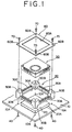
- FIG. 1 is an exploded perspective view of a mounting structure for a heat sink showing a first embodiment of the present invention.
- An integrated circuit package 20 mounted on a printed circuit board 10 has a plurality of pins 20A for electric connection, and the pins 20A are connected by soldering to a conductor pattern (not shown) formed on a front or rear face of the printed circuit board 10.
- a guide member 30, made of aluminum and thus having a high heat conductivity has a frame portion 30A having an inner periphery substantially equal to an outer periphery of the integrated circuit package 20, support post portions 30B protruding in upward and downward directions at the four corners of the frame portion 30A, and a plurality of fin portions 30C protruding in the upward direction from the frame portion 30A.
- the frame portion 30A, support post portions 30B and fin portions 30C are formed, for example, as a unitary member.
- the guide member 30 is disposed around the periphery of the integrated circuit package 20 on the printed circuit board 10, and the support post portions 30B are fixed directly to the printed circuit board 10.
- screws 40 are individually screwed into the four support post portions 30B of the guide member 30 from the rear face side of the printed circuit board 10 through four threaded holes 10A formed in the printed circuit board 10 so that the guide member 30 is fixed to the printed circuit board 10.
- the guide member 30 may be fixed to the printed circuit board 10 by adhering the support post portions 30B to the upper face of the printed circuit board 10.
- the heat sink 50 is seated on the inner periphery of the guide member 30 such that a lower face thereof may be closely contacted with the upper face of the integrated circuit package 20.
- a cover 60 has an opening 60A for exposing the upper face of the heat sink 50 and threaded holes 60B, and the cover 60 is fixed to the guide member 30 by screwing screws 70 into the support post portions 30B through threaded holes 60B.
- the shape of the cover 60 is set such that, when the cover 60 is fixed to the guide member 30, it covers over outer peripheral edge portions of the heat sink 50 to such a degree that it does not deteriorate the heat radiation property of the heat sink 50.
- FIG. 2 is an exploded perspective view showing an example of a construction of the heat sink 50 of FIG. 1.
- the heat sink 50 has a base member 82 having heat radiation fins 81 on an upper face thereof, a fan assembly (air blasting means) 83 provided on the upper face of the base member 82 for blasting (i.e. blowing) air to the heat radiation fins 81, and a cover member 84 for covering over an upper portion of the base member 82.
- the base member 82 and the cover member 84 are formed from aluminum having a high heat conductivity similar to the guide member 30 of FIG. 1, and a lower face of the base member 82 is formed flat in order to reduce the contact heat resistance with an integrated circuit package 20 (refer to FIG. 1).
- Support posts 85A, 85B, 85C and 85D are provided at the four corners of the upper face of the base member 82, and the heat radiation fins 81 are provided so as to cover over the fan assembly 83 exempt portions at which the support posts are formed.
- the support posts 85A, 85B, 85C and 85D and the heat radiation fins 81 are formed integrally with a plate-formed portion of the base member 82.
- a ventilation path 86 is defined between the fan assembly 83 fixed to the base member 82 and the heat radiation fins 81.
- the fan assembly 83 has a motor(not shown)having a shaft 87 extending substantially perpendicularly to the upper face of the base member 82, a propeller 88 rotated by the shaft 87, and a printed circuit board 89 having a driver circuit for the motor.
- the cover member 84 is fixed to the support posts 85A, 85B, 85C and 85D of the base member 82 by means of screws 92.
- the cover member 84 has an opening 90 which is communicated with the ventilation path 86 by way of the propeller 88 of the fan assembly 83, and further has an annular projection 91 positioned a little outwardly of a locus of rotation of the propeller 88.
- the annular projection 91 limits the ventilation path 86, the static pressure difference between the opening 90 of the cover 84 and the ventilation path 86 is increased, and efficient blasting of air can be performed.
- the inclination angle of the propeller 88 may be reversed or the direction of rotation of the fan assembly 83 may be reversed so that air may be caused to flow in the other direction from the heat radiation fins 81 of the base member 82 toward the opening 90 of the cover 84.
- the fixation location of the fan assembly 83 to the base member 82 is offset in the direction toward 85A of the four support posts 85A, 85B, 85C and 85D, and a wall face of the support post 85A is provided so as to extend in the directions toward the support posts 85B and 85D.
- the reason why the center of rotation of the fan assembly 83 is displaced from the center (for example, the center of gravity) of the base member 82 is that the air blasting capacity of the fan assembly 83 is higher at a peripheral portion than a central portion thereof, and the location where the air blasting capacity is high and the center (normally a central portion of the package) of heat generation of the integrated circuit package 20 (refer to FIG. 1) are made to substantially coincide with each other to achieve effective heat radiation.
- the reason why, when the fan assembly 83 is to be offset in such a manner as described above, the wall face of the support post 85A on the side on which the fan assembly 83 is to be offset is caused to extend is that it is intended so that communication of air to the heat radiation fins 81 may be performed equally. While the fan assembly 83 in the present example is fixed to the base member 82, the fan assembly 83 may be fixed to the cover member 84 so that heat may not be transmitted readily from the integrated circuit board 20 (refer to FIG. 1) to the fan assembly. Consequently, the reliability of the fan assembly 83 is improved.
- heat radiation of the integrated circuit package 20 can be achieved very excellently with the construction of, for example, FIG. 1.
- a heat sink of a high performance of this type it is very important to assure a heat radiation area of the heat sink in order to maintain a high heat radiation characteristic.
- FIG. 3 is an exploded perspective view of a mounting structure for a heat sink showing a second embodiment of the present invention.
- the present embodiment is characterized, in contrast with the first embodiment of FIG. 1, in that the present invention is applied to a comparatively large integrated circuit package 21.
- the integrated circuit package 21 is mounted at pins 21A thereof onto a printed circuit board 11 in a similar manner as in the first embodiment of FIG. 1.
- a guide member 31 integrally has a frame member 31A, support post portions 31B and fin portions 31C.
- the guide member 31 is formed from aluminum having a high heat conductivity.
- An outer periphery of the frame portion 31 of the guide member 31 is, in the present embodiment, substantially equal to an outer periphery of the integrated circuit package 21, and the support post portions 31B protrude only in an upward direction of the frame portion 31A. Accordingly, a lower face of the guide member 31 can be fixed readily by adhesion to edge portions of an upper face of the integrated circuit package 21.
- the heat sink 50 is seated on an inner periphery of the guide member 31 such that a lower face thereof is closely contacted with the upper face of the integrated circuit package 21, and a cover 60 is provided such that it covers over outer peripheral edge portions of an upper face of the heat sink 50.
- the heat sink 50 and the cover 60 are same as those in the first embodiment of FIG. 1.
- the present embodiment similarly as in the case according to the first embodiment of FIG. 1, efficient heat radiation of the integrated circuit package 21 becomes possible, and facilitation of a mounting operation of the heat sink 50 is allowed. While the outer periphery of the integrated circuit package 21 in the present embodiment is substantially equal to the outer periphery of the frame portion 31A of the guide member 31, the concept of the present embodiment can be applied also to another case wherein the outer periphery of the integrated circuit package 21 is greater than the outer periphery of the frame portion 31A. In the case according to the conventional example described with reference to FIGS.
- FIGS. 4A and 4B are views for explaining other covers which can be used in place of the cover 60 in the first embodiment of FIG. 1, the second embodiment of FIG. 3 and so forth.
- a cover 61 is formed from a resilient plate member.
- Reference character 61A denotes an opening for exposing a heat sink
- reference character 61B denotes a threaded hole for screwing the cover 61 to a support post of a guide member.
- portions 61C corresponding to opposing two sides of the cover 61 have a shape curved toward the side of a heat sink not shown, and when the cover 61 is screwed, for example, to the support post portions 30B of the guide member 30 in the embodiment of FIG. 1, a resilient restoring force of the curved portions 61C acts to press the heat sink 50 against the integrated circuit package 20. Accordingly, by using the cover 61 formed from a resilient plate member having such curved portions, when the shape and the dimensions of the heat sink 50 or the mounting height of the integrated circuit package 20 is dispersed due to the manufacturing technique, the heat sink 50 can always be closely contacted well with the integrated circuit package 20 irrespective of such dispersion, and it is possible to maintain a high heat radiation characteristic.
- a cover 62 is fixed to support post portions of a guide member not by screwing, but the cover 62 is fixed to a guide member 31' by forming arresting (i.e. engaging) portions 31D of the shape of a depression on outer walls of support post portions 31B' of the guide member 31' and engaging pawls 62B of the cover 62 with the arresting portions 31D of the support post portions 31B'.
- Reference character 62A denotes an opening for exposing a heat sink
- 62C denotes a curved portion of the cover 62.
- the cover 62 is obtained by working a resilient plate member similarly as in the example of FIG. 4A.
- FIG. 5 is a side elevational view showing a further example of a cover which can be used in the first embodiment of FIG. 1, the second embodiment of FIG. 3 and so forth.
- the present cover is characterized, in contrast with the covers of the embodiments described so far, in that one end thereof is mounted for pivotal motion on a guide member.
- An integrated circuit package 22 is mounted on a printed circuit board 12 by means of pins 22A.
- Support post portions 32B of a guide member 32 protrude only in an upward direction from a frame portion 32A, and the guide member 32 is adhered at a lower face thereof to the integrated circuit package 22.
- An outer periphery of the integrated circuit package 22 is substantially equal to an outer periphery of the frame portion 32A of the guide member 32.
- Reference character 32C denotes a plurality of fin portions which protrude in the upward direction from the frame portion 32A of the guide member 32.
- a heat sink 51 having heat radiation fins 51A integrally thereon is used, and the heat sink 51 is pressed in the downward direction in FIG. 5 by a cover 63 so that a lower face thereof may be closely contacted with an upper face of the integrated circuit package 22.
- One end 63A of the cover 63 is supported for pivotal motion on the support post portions 32B positioned on the right side in FIG. 5, and the other end 63B of the cover 63 which is shaped in a hook shape is arrested at projections 32D provided on the support post portions 32B positioned on the left side in FIG. 5.
- FIG. 6 is a side elevational view of a mounting structure for a heat sink showing a third embodiment of the present invention.
- the present embodiment is characterized, in contrast with the first embodiment of FIG. 1, in that part of support post portions of a guide member is formed as a separate member.
- An integrated circuit package 23 is mounted at pins 32A thereof on a printed circuit board 13.
- a guide member 33 having an inner periphery substantially equal to an outer periphery of the integrated circuit package 23 has a frame portion 33A and support post portions 33B which are formed integrally with each other, and pipe members 33C separate from them.
- the support post portions 30B of the guide member 30 are formed integrally with the frame portion 30A such that they protrude in the upward and downward directions, in the present embodiment, only portions (33B) of the support post portions which protrude in the upward direction are integrated with the frame member 33A while the other portions (pipe members 33C) of the support post portions which protrude in the downward direction are separate members from the frame member 33A.
- Each of the pipe members 33C is fixed at a lower end thereof to a printed circuit board 13 by means of a screw 40, and an upper face of the pipe member 33C is fixed to a guide member body, for example, by adhesion.
- the guide member 33 and the integrated circuit package 23 may be fixed to each other by adhesion.
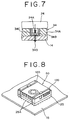
- FIG. 7 is a partial sectional view of a mounting structure for a heat sink showing a fourth embodiment of the present invention.
- the present embodiment is characterized, in contrast with the embodiments described so far, in that a guide member further has a socket structure for removably mounting a pin of an integrated circuit package.
- a guide member 34 is fixed directly to a printed circuit board 14 similarly as in the first embodiment of FIG. 1 and so forth.
- the guide member 34 has a heat radiation portion 34A made of aluminum having a high heat conductivity, a plurality of socket chambers provided at a plurality of locations of the heat radiation portion 34A in a direction of a plane and each defined by an insulator 34B such as a resin, a contact 34C provided in each of the socket chambers for fitting with a pin 24A of the IC package 24, and a lead 34D connected to the contact 34C and mounted on the printed circuit board 14 by soldering or the like.
- FIG. 8 is a perspective view of a mounting structure for a heat sink showing a fifth embodiment of the present invention.
- An integrated circuit package 25 mounted on a printed circuit board 15 has a plurality of pins 25A for electric connection, and each of the pins 25A is connected to a conductor pattern(not shown) formed on the front surface or the rear surface of the printed circuit board 15 by soldering.
- a heat sink 50 shown in FIG. 2 is placed on the integrated circuit package 25 such that the bottom face thereof closely contacts with the upper face of the integrated circuit package 25.
- the size of the bottom face of the heat sink 50 is substantially equal to the size of the upper face of the integrated circuit package 25.
- a belt member 120 is used.
- the belt member 120 is provided around the integrated circuit package 25 and the heat sink 50 through a gap between the printed circuit board 15 and the integrated circuit package 25.
- two belt members 120 are provided corresponding to the opposite ends of the heat sink 50.
- FIGS. 9A and 9B are a side elevational view and a plan view showing an example of the belt member shown in FIG. 8.
- the belt member 120 has a belt body 122 in the form of a tapering belt made of, for example, nylon, and a head portion 124 provided integrally with the belt body 122 at an end portion of the belt body 122.
- An opening 128 into the inside of which an arresting (engaging) pawl 126 extends is formed in the head portion 124.
- the belt body 122 has a ratchet 130 formed thereon which engages the arresting pawl 126 when the belt body 122 is inserted from the tapering portion thereof into the opening 128 of the head portion 124.
- the shapes of the ratchet portion 130 and the arresting pawl 126 are set so that, when it is tried to insert the belt body 122 from the tapering portion thereof into the opening 128 of the head portion 124, it can be inserted readily in the insertion direction, but after the belt body 122 is inserted once, it cannot be pulled out any more.
- FIGS. 10A and 10B are perspective views of the latch portion of the belt member.
- FIG. 10A shows the latch portion in the case wherein the belt member of FIGS. 9A and 9B is employed, and in this instance, by pulling the tapering portion 122A of the belt body 122, which has been inserted into the opening 128 of the head portion 124 from the side of the heat sink 50, in an upward direction while the head portion 124 is pressed against the heat sink 50 of FIG. 8, the belt member 120 can be tightened to closely contact the heat sink 50 firmly with the integrated circuit package 25 in FIG. 8.
- a belt member 120' made of a material having a uniform thickness and a uniform width and having a comparatively high surface friction is used, and the opposite ends of the belt member 120' are folded back using a latch member 132 having three rectangular holes in a longitudinal direction thereof to closely contact the heat sink 50 in FIG. 8 firmly with the integrated circuit package 25.
- an insulator such as nylon is employed as a material of the belt member in order to prevent short-circuiting between the pins 25A.
- a material of the belt member it is also possible to employ a metal material the surface of which is processed by insulation processing such as by covering over the surface with a resin.
- a heat contracting tube may be employed for the belt member, and the heat sink 50 in FIG. 8 may be closely contacted firmly with the integrated circuit package 25 by heating the heat contracting tube to contract the same.
- the thickness of the belt body 122 can be set smaller than 0.5 mm from the point of view of the strength of the belt body 122, but when formation of the racket 130 on the belt body 122 is taken into consideration, the thickness of the belt body 122 cannot be set smaller than 1 mm.
- a portion of the belt body 122 which corresponds to the integrated circuit board 25 and on which the ratchet 130 need not be formed is formed with a reduced thickness.
- slopes are provided on the belt 122 as shown in FIGS. 9A and 9B to prevent deterioration of the strength of the belt body 122.
- the opposite ends of the reduced thickness portion 122B may be formed by rounding processing in place of the slopes.
- the belt members are interposed between the integrated circuit package 25 and the printed circuit board 15.
- the reduced thickness portions 122B of the belt members correspond to the bottom face of the integrated circuit package 25, the belt members set once will not be pulled off from within the gap by mechanical vibrations or the like.
- the heat sink 50 is placed onto the integrated circuit package 25, the opposite ends of the belt members are latched, thereby completing mounting of the heat sink 50.
- the heat sink can be mounted onto the integrated circuit package 25 at a low cost and readily without particularly using any other part. Further, since the area over which the surface of the heat sink is covered is very small, an effective heat radiation action of the heat sink can be maintained.
- the belt member is formed from a resin such as nylon
- the elongation of the reduced thickness portion is sometimes so great that the clamping force is not stable.
- the belt member when the belt member is used under a high temperature environment, the belt member likely undergoes elongation, which sometimes makes the mounting condition of a heat sink unstable.
- the belt member is constituted from a resin belt (nylon belt) elongated beyond an elastic limit after molding thereof.
- the elastic limit is a maximum stress a solid body can stand without undergoing permanent deformation.
- An example of a method of manufacturing such resin belt includes a step of forming a belt member of a desired profile by molding and another step of applying a predetermined tensile stress to the belt member.
- the belt member may be elongated while it is heated, for example, to 95 to 100 °C. Further, in order to prevent deformation by moisture absorption during use, the belt member may be elongated in water boiling at 95 to 100 °C. Where a belt member constituted from a resin belt elongated beyond its elastic limit in this manner is employed, the belt member is elongated little when or after a heat sink is mounted onto an integrated circuit package, and consequently, a stabilized clamping force can be obtained.
- the reduced thickness portion of the belt member should be formed with a cross section of a circular shape having the diameter of 0.4 to 0.5 mm.
- the belt member having the reduced thickness of the circular cross section can have a high strength when applied to an integrated circuit package of the same pin distance comparing with another belt member having a reduced thickness portion of a rectangular cross section.
- a slit may be formed in the reduced thickness portion 122B of the belt member in its longitudinal direction.
- pins of a small distance on an integrated circuit package are inserted into the slit.
- the belt member having the reduced thickness portion of a rectangular cross section of a great width can be adapted to an integrated circuit package of a small pin distance.
- a guide may be provided on the heat sink as shown in FIGS. 11A, 11B and 11C in order to prevent stress concentration of the belt member upon its contacting portion with an upper face edge portion of the heat sink or prevent displacement of the belt member in its widthwise direction.
- a guide groove 84A is formed obliquely at an edge portion of a cover member 84 for a heat sink 50. Where such guide groove is formed, occurrence of stress concentration on the belt member can be prevented and besides displacement of the belt member in its widthwise direction can be prevented.
- two projection guides 84B are formed with a width corresponding to the width of a belt member at a side end of a cover member 84.
- projection guides 84C are provided uprightly at an edge portion of an upper face of a cover member 84. Where the projection guides shown in FIG. 11B or 11C are formed on the cover member 84, displacement of the belt member in its widthwise direction can be prevented.
- FIGS. 11A, 11B and 11C since only part of a heat sink is shown, only one guide is shown, it is desirable to actually provide guides at two opposing locations on a single belt member. Further, taking the universality in use into consideration, a guide may be provided in advance at a location at which a belt member does not contact with the guide when the cover member is used.
- FIG. 12 is an exploded perspective view of a mounting structure for a heat sink showing a fifth embodiment of the present invention.
- An integrated circuit package 26 of a comparatively large size is mounted on a printed circuit board 16.
- Reference character 26A denotes a pin for connection of the integrated circuit package 26.
- the guide 134 has pawls 134A bent in a downward direction at four locations of an outer peripheral edge portion, and pawls 134B bent in an upward direction at four locations on an inner peripheral edge portion.
- the distance between mutually opposing ones of the pawls 134A corresponds to the width of the integrated circuit package 26, and the distance between mutually opposing ones of the pawls 134B corresponds to the width of the heat sink 50.
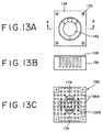
- FIGS. 13A, 13B and 13C are views showing a first embodiment of the heat sink of the present invention.
- FIG. 13A is a plan view of the heat sink
- FIG. 13B a side elevational view of the heat sink
- FIG. 13C a plan view of a base member of the heat sink.
- FIG. 14 is a sectional view of the heat sink taken along line A-A.
- the present heat sink has a base member 136 having a lower face closely contacted with an upper face of an integrated circuit package and an upper face from which a plurality of heat radiation fins 136A and 136B extend, and a cover 138 secured to the base member 136 for closing an upper portion of the base member 136.
- a fan mounting portion 140 is formed on the rear face of the cover 138, and a fan assembly 142 serving as air blasting means is secured to the fan mounting portion 140.
- the fan assembly 142 is constituted from a stator 146 force fitted in and secured to the fan mounting portion 140 and having a coil 144 provided on an outer peripheral portion thereof, a shaft 150 provided uprightly at the center of the stator 146 by way of a bearing 148, a rotor 156 secured to the shaft 150 and having a magnet 152 secured to an inner peripheral wall thereof and a propeller 154 secured to an outer peripheral wall thereof, and a printed circuit board 160 to which a lead 158 is connected.
- a motor driver circuit not shown is mounted on the printed circuit board 160. It is to be noted that, in FIG.
- reference numeral 162 denotes a ring yoke, 164 a yoke, 166 a cut washer mounted on the shaft 150, and 168 a spring for biasing the shaft 150 upwardly.
- reference numeral 170 denotes an opening provided in the cover 138 for allowing circulation of air therethrough, and 172 an annular projection for assurance of a static pressure difference. The opening 170 is provided at a plural number of points along a locus of rotation of the propeller 154.
- the base member 136 and the fins 136A and 136B are formed as a unitary member from aluminum which has a high heat radiation property. Of those fins, the fins 136B at a portion corresponding to the fan assembly 142 are set shorter than the fins 136A at the other portion. Further, as shown in FIG. 13C, separators 174 constituted from portions of a cylinder which extend from the base member 136 along the locus of rotation of the propeller 154 are provided on the base member 136. The separators 174 are formed integrally with the base member 136 similarly as the fins 136A and 136B.
- the length of fins at a central portion of a portion corresponding to a fan assembly was set to 3mm
- the length of fins at peripheral portions of the portion corresponding to the fan assembly was set to 8 mm and the length of the remaining fins was set to 18mm, a very good heat radiation property was successfully obtained.
- FIGS. 15A and 15B are views showing other examples of an arrangement of fins.
- a fin 136C just below the center of a fan assembly is formed so as to have a column-like shape so that wind may flow smoothly therearound.
- the height of the fin 136C is equal to the height of fins 136B.
- the sectional area of fins 136D just below the center of a fan assembly are made so small that wind may smoothly flow therethrough. Where there is a sufficient space for the arrangement of the fins, the distance between the fins may be increased so that wind may flow smoothly between them. Also in FIGS.
- arrow marks indicate flows of wind when the air blasting direction of the fan assembly is such that air is taken in at an upper face of a heat sink.
- the air blasting direction of the fan assembly may be set such that it may be a discharging direction at the upper face of the heat sink by reversing the direction of rotation of the motor or like means.
- the sectional shape of fins may be a round shape or a polygonal shape.
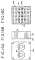
- FIGS. 16A, 16B and 16C are views showing a second embodiment of the heat sink of the present invention.
- FIG. 16A is a plan view of the same
- FIG. 16B a side elevational view of the same
- FIG. 16C a plan view of a base member of the same.
- two fan assemblies 142 are provided on a cover 138, and corresponding to them, shorter fins 136B are disposed at predetermined positions as shown in FIG. 16C.
- shield plates 176 are provided on the opposite sides with respect to the two fan assemblies 142.
- the shield plates 176 are, for example, integral with a base member 136.
- an effect that provision of a mounting structure for a heat sink which is high in cooling efficiency and is easy to mount is possible is provided. Further, according to the present invention, there is another effect that provision of a heat sink having a high cooling efficiency is possible.
Claims (10)
- Ensemble formé d'un module à circuits intégrés, d'un dissipateur thermique pour le module à circuits intégrés, et d'une structure de montage pour le montage dudit dissipateur thermique sur le module à circuits intégrés lorsque le module à circuits intégrés est monté sur une carte à circuits imprimés, ladite structure de montage comprenant:caractérisé en ce que ledit élément de guidage est réalisé en aluminium.un élément de guidage possédant une partie formant cadre et une pluralité de parties formant montants de support, ladite partie formant cadre possédant une périphérie intérieure correspondant à une périphérie extérieure dudit module à circuits intégrés et des parties formant montants de support faisant saillie à partir de ladite partie formant cadre dans une direction perpendiculaire à ladite carte à circuits imprimés, ledit élément de guidage pouvant être fixé à ladite carte à circuits imprimés, ledit dissipateur thermique étant en appui, d'une manière non adhésive, sur ledit module à circuits intégrés de telle sorte qu'une surface latérale dudit dissipateur thermique est étroitement en contact avec une face intérieure de chacune desdites parties formant montants de support;
- Ensemble selon la revendication 1, dans lequel lesdites parties formant montants de support de l'élément de guidage font saillie dans des directions ascendants et descendants dudit élément de guidage; et
des faces inférieures desdites parties formant montants de support peuvent être fixées directement sur ladite carte à circuits imprimés. - Ensemble selon la revendication 1 ou 2, dans lequel lesdites parties formant montants de support sont intégrés à ladite partie formant cadre.
- Ensemble selon la revendication 2, dans lequel les portions desdites parties formant montants de support, qui font saillie dans la direction ascendante, sont intégrées à ladite partie formant cadre, tandis que les autres portions desdites parties formant montants de support, qui font saillie dans la direction descendante, sont agencées sous la forme d'éléments séparés de ladite partie formant cadre.
- Ensemble selon l'une quelconque des revendications précédentes, comportant en outre un capot fixé audit élément de guidage au niveau desdites parties formant montants de support de sorte que ledit capot recouvre des parties de bords périphériques extérieurs d'une face supérieure dudit dissipateur thermique.
- Ensemble selon la revendication 5, dans lequel ledit capot est formé d'un matériau en forme de plaque élastique, dont des parties, qui sont situées entre des parties de cet élément correspondant auxdites parties formant montants de support, possèdent une forle qui est incurvée en direction dudit côté du dissipateur thermique.
- Ensemble selon la revendication 5 ou 6, dans lequel ledit capot est vissé sur des faces supérieures desdites parties formant montants de support.
- Ensemble selon la revendication 5, 6 ou 7, dans lequel ledit capot comporte des cliquets dans des parties de ce capot correspondant auxdites parties formant montants de support; et
lesdites parties formant montants de support possèdent une forme, au moyen de laquelle lesdits cliquets engrènent avec lesdites parties. - Ensemble selon l'une quelconque des revendications 5 à 8, comprenant en outre des moyens pour monter une extrémité dudit capot de manière pour permettre un mouvement de pivotement sur lesdites parties formant montants de support; et
des moyens pour engrener de façon amovible avec l'autre extrémité dudit capot au niveau desdites parties formant montants de support. - Ensemble selon l'une quelconque des revendications précédentes, dans lequel ledit élément de guidage comporte en outre une structure en forme de douille pour le montage amovible d'une broche dudit module à circuits intégrés; et
des moyens pour engrener de façon amovible avec l'autre extrémité duladite structure de douille possède un contact destiné à coopérer avec ladite broche, et un conducteur raccordé audit contact et monté sur la carte à circuits imprimés.
Priority Applications (2)
| Application Number | Priority Date | Filing Date | Title |
|---|---|---|---|
| EP98203333A EP0908949B1 (fr) | 1993-03-19 | 1994-03-10 | Structure d'assemblage pour un dissipateur de chaleur et procédé pour la fabrication de la structure d'assemblage |
| EP98203331A EP0893828B1 (fr) | 1993-03-19 | 1994-03-10 | Dissipateur de chaleur |
Applications Claiming Priority (9)
| Application Number | Priority Date | Filing Date | Title |
|---|---|---|---|
| JP60004/93 | 1993-03-19 | ||
| JP6000493 | 1993-03-19 | ||
| JP6000493 | 1993-03-19 | ||
| JP225650/93 | 1993-09-10 | ||
| JP22565093 | 1993-09-10 | ||
| JP22565093 | 1993-09-10 | ||
| JP28413/94 | 1994-02-25 | ||
| JP2841394 | 1994-02-25 | ||
| JP6028413A JP2901867B2 (ja) | 1993-03-19 | 1994-02-25 | ヒートシンク及びヒートシンクの取付構造 |
Related Child Applications (2)
| Application Number | Title | Priority Date | Filing Date |
|---|---|---|---|
| EP98203333A Division EP0908949B1 (fr) | 1993-03-19 | 1994-03-10 | Structure d'assemblage pour un dissipateur de chaleur et procédé pour la fabrication de la structure d'assemblage |
| EP98203331A Division EP0893828B1 (fr) | 1993-03-19 | 1994-03-10 | Dissipateur de chaleur |
Publications (3)
| Publication Number | Publication Date |
|---|---|
| EP0616366A2 EP0616366A2 (fr) | 1994-09-21 |
| EP0616366A3 EP0616366A3 (fr) | 1995-07-26 |
| EP0616366B1 true EP0616366B1 (fr) | 2002-07-24 |
Family
ID=27286188
Family Applications (3)
| Application Number | Title | Priority Date | Filing Date |
|---|---|---|---|
| EP98203333A Expired - Lifetime EP0908949B1 (fr) | 1993-03-19 | 1994-03-10 | Structure d'assemblage pour un dissipateur de chaleur et procédé pour la fabrication de la structure d'assemblage |
| EP98203331A Expired - Lifetime EP0893828B1 (fr) | 1993-03-19 | 1994-03-10 | Dissipateur de chaleur |
| EP94103679A Expired - Lifetime EP0616366B1 (fr) | 1993-03-19 | 1994-03-10 | Dissipateur thermique et structure d'assemblage associée |
Family Applications Before (2)
| Application Number | Title | Priority Date | Filing Date |
|---|---|---|---|
| EP98203333A Expired - Lifetime EP0908949B1 (fr) | 1993-03-19 | 1994-03-10 | Structure d'assemblage pour un dissipateur de chaleur et procédé pour la fabrication de la structure d'assemblage |
| EP98203331A Expired - Lifetime EP0893828B1 (fr) | 1993-03-19 | 1994-03-10 | Dissipateur de chaleur |
Country Status (5)
| Country | Link |
|---|---|
| US (4) | US5559674A (fr) |
| EP (3) | EP0908949B1 (fr) |
| JP (1) | JP2901867B2 (fr) |
| KR (1) | KR100190426B1 (fr) |
| DE (3) | DE69433878T2 (fr) |
Families Citing this family (98)
| Publication number | Priority date | Publication date | Assignee | Title |
|---|---|---|---|---|
| JP3069819B2 (ja) * | 1992-05-28 | 2000-07-24 | 富士通株式会社 | ヒートシンク並びに該ヒートシンクに用いるヒートシンク取付具及びヒートシンクを用いた可搬型電子装置 |
| GB2298520B (en) * | 1995-03-03 | 1999-09-08 | Hong Chen Fu In | Heat sink device for integrated circuit |
| JP3058818B2 (ja) * | 1995-10-05 | 2000-07-04 | 山洋電気株式会社 | 電子部品冷却用ヒートシンク |
| JPH09149598A (ja) * | 1995-11-20 | 1997-06-06 | Seiko Epson Corp | 冷却ファンおよび冷却ファン組立体 |
| US5896917A (en) | 1996-02-22 | 1999-04-27 | Lemont Aircraft Corporation | Active heat sink structure with flow augmenting rings and method for removing heat |
| GB2312324B (en) * | 1996-04-19 | 2000-11-15 | Hong Chen Fu In | Fan/pins seat assembly for an integrated circuit |
| JP3217265B2 (ja) * | 1996-06-05 | 2001-10-09 | 株式会社ピーエフユー | ヒートシンク装置 |
| JP3206436B2 (ja) * | 1996-07-03 | 2001-09-10 | 松下電器産業株式会社 | ヒートシンク装置 |
| JP2959506B2 (ja) * | 1997-02-03 | 1999-10-06 | 日本電気株式会社 | マルチチップモジュールの冷却構造 |
| JP4290232B2 (ja) * | 1997-02-24 | 2009-07-01 | 富士通株式会社 | ヒートシンクとそれを使用する情報処理装置 |
| US6501652B2 (en) | 1997-02-24 | 2002-12-31 | Fujitsu Limited | Heat sink and information processor using it |
| JP3488060B2 (ja) | 1997-11-12 | 2004-01-19 | 株式会社Pfu | 薄型電子装置の放熱装置 |
| US6114761A (en) * | 1998-01-20 | 2000-09-05 | Lsi Logic Corporation | Thermally-enhanced flip chip IC package with extruded heatspreader |
| US5978219A (en) * | 1998-03-09 | 1999-11-02 | Lin; Liken | Heat dissipating device |
| JP3619670B2 (ja) * | 1998-05-27 | 2005-02-09 | アルプス電気株式会社 | 電子機器 |
| US6109890A (en) * | 1998-07-02 | 2000-08-29 | Sunonwealth Electric Machine Industry Co., Ltd. | Miniature blower assembly for outputting air in a certain direction |
| US7584780B1 (en) | 1998-12-09 | 2009-09-08 | Lemont Aircraft Corporation | Active heat sink structure with flow augmenting rings and method for removing heat |
| JP3255133B2 (ja) * | 1999-01-07 | 2002-02-12 | 松下電器産業株式会社 | Dcブラシレスファン |
| US6069794A (en) * | 1999-02-08 | 2000-05-30 | Chuang; Wen-Hao | Bushing for combining fan and heat sink |
| US6219238B1 (en) | 1999-05-10 | 2001-04-17 | International Business Machines Corporation | Structure for removably attaching a heat sink to surface mount packages |
| JP4144972B2 (ja) | 1999-05-31 | 2008-09-03 | 山洋電気株式会社 | 一軸受型永久磁石電動機及び一軸受型ファンモータ |
| EP1239359A4 (fr) * | 1999-06-11 | 2007-12-12 | Jiung-Jung Wang | Dissipateur thermique pour une unite centrale d'un ordinateur portable |
| US6552464B1 (en) * | 1999-11-09 | 2003-04-22 | Siemens Canada Limited | Totally integrated engine cooling module for DC motors |
| TWI222344B (en) * | 1999-12-09 | 2004-10-11 | Advanced Rotary Systems Llc | Cooler for electronic devices |
| US6659169B1 (en) | 1999-12-09 | 2003-12-09 | Advanced Rotary Systems, Llc | Cooler for electronic devices |
| JP4386219B2 (ja) | 2000-03-31 | 2009-12-16 | 富士通株式会社 | 放熱機構及び当該放熱機構を有する電子機器 |
| JP2001284865A (ja) | 2000-03-31 | 2001-10-12 | Fujitsu Ltd | ヒートシンク及びその製造方法、並びに、当該ヒートシンクを有する電子機器 |
| JP4441978B2 (ja) * | 2000-04-27 | 2010-03-31 | パナソニック株式会社 | 送風装置 |
| US6441485B1 (en) * | 2000-05-11 | 2002-08-27 | Amkor Technology, Inc. | Apparatus for electrically mounting an electronic device to a substrate without soldering |
| US6434002B1 (en) * | 2000-07-31 | 2002-08-13 | Wen-Chen Wei | Structure computer heat dissipater |
| US6657131B2 (en) * | 2000-12-08 | 2003-12-02 | Intel Corporation | I/C package / thermal-solution retention mechanism with spring effect |
| JP3503822B2 (ja) * | 2001-01-16 | 2004-03-08 | ミネベア株式会社 | 軸流ファンモータおよび冷却装置 |
| KR100693168B1 (ko) * | 2001-05-10 | 2007-03-13 | 엘지전자 주식회사 | 인쇄회로기판 및 그 제조방법 |
| US6429513B1 (en) | 2001-05-25 | 2002-08-06 | Amkor Technology, Inc. | Active heat sink for cooling a semiconductor chip |
| US6653755B2 (en) * | 2001-05-30 | 2003-11-25 | Intel Corporation | Radial air flow fan assembly having stator fins surrounding rotor blades |
| US6640882B2 (en) * | 2001-07-31 | 2003-11-04 | Agilent Technologies, Inc. | Removable mounting clip attaches a motorized fan to an active heat sink and then the entire assembly to a part to be cooled |
| KR100422037B1 (ko) * | 2001-08-09 | 2004-03-12 | 삼성전기주식회사 | 광경로 변환형 가변 광학 감쇠기 |
| US7252139B2 (en) * | 2001-08-29 | 2007-08-07 | Sun Microsystems, Inc. | Method and system for cooling electronic components |
| US6606246B2 (en) * | 2001-09-21 | 2003-08-12 | Intel Corporation | Method and apparatus for retaining cooling apparatus and bus bar |
| US6705795B2 (en) | 2001-10-15 | 2004-03-16 | Hewlett-Packard Development Company, L.P. | Attachment mechanism |
| AT413163B (de) * | 2001-12-18 | 2005-11-15 | Fotec Forschungs Und Technolog | Kühlvorrichtung für einen chip sowie verfahren zur herstellung |
| TW511885U (en) * | 2002-01-30 | 2002-11-21 | Hon Hai Prec Ind Co Ltd | Assembly of heat dissipation apparatus |
| US6639796B2 (en) * | 2002-01-24 | 2003-10-28 | Agilent Technologies, Inc. | Fastenerless clip for quick installation and removal of system components in a computer system |
| US6570763B1 (en) * | 2002-02-12 | 2003-05-27 | Hon Hai Precision Ind. Co., Ltd. | Heat sink securing means |
| US6638033B2 (en) * | 2002-03-28 | 2003-10-28 | Chin-Wen Wang | Magnetic-levitated cooling circulatory mechanism |
| US6600661B1 (en) * | 2002-04-08 | 2003-07-29 | Hewlett-Packard Development Company, L.P. | Method and apparatus for supporting a circuit component |
| US6611427B1 (en) * | 2002-06-03 | 2003-08-26 | Accton Technology Corporation | Flexible fan module |
| US6600650B1 (en) * | 2002-06-11 | 2003-07-29 | Cheng-Ping Lee | Fastening device of CPU heat sink |
| TW590243U (en) * | 2002-06-28 | 2004-06-01 | Hon Hai Prec Components Co Ltd | Lateral slide resisting structure for heat sink |
| TW540988U (en) * | 2002-10-04 | 2003-07-01 | Hon Hai Prec Ind Co Ltd | A heat dissipating assembly |
| TW545885U (en) * | 2002-11-29 | 2003-08-01 | Hon Hai Prec Ind Co Ltd | Heat dissipation assembly |
| US7539017B2 (en) * | 2003-03-27 | 2009-05-26 | Kuo Ta Chang | Heat dissipating device for central processor |
| CN100378975C (zh) * | 2003-05-07 | 2008-04-02 | 富士通株式会社 | 冷却部件、基板和电子设备 |
| CN1578614B (zh) | 2003-06-30 | 2010-04-21 | 山洋电气株式会社 | 轴流风扇装置和发热体冷却装置 |
| US6958909B2 (en) * | 2003-09-19 | 2005-10-25 | Matsushita Electric Industrial Co., Ltd. | Electronic apparatus |
| TWI241382B (en) * | 2003-10-27 | 2005-10-11 | Sunonwealth Electr Mach Ind Co | Airflow guiding structure for a heat dissipating fan |
| DE102004037656B4 (de) * | 2004-08-03 | 2009-06-18 | Infineon Technologies Ag | Elektronikmodul mit optimierter Montagefähigkeit und Bauteilanordnung mit einem Elektronikmodul |
| JP4197668B2 (ja) * | 2004-08-17 | 2008-12-17 | 株式会社東芝 | インターフェイスモジュール付lsiパッケージとインターフェイスモジュール及び接続保持機構 |
| TWI305612B (en) * | 2004-08-27 | 2009-01-21 | Delta Electronics Inc | Heat-dissipating fan |
| CN2757508Y (zh) * | 2004-12-04 | 2006-02-08 | 鸿富锦精密工业(深圳)有限公司 | 散热装置 |
| CN2875001Y (zh) * | 2005-12-23 | 2007-02-28 | 鸿富锦精密工业(深圳)有限公司 | 散热器 |
| JP2007281100A (ja) * | 2006-04-04 | 2007-10-25 | Nippon Densan Corp | ヒートシンクファンユニット |
| DE102006025453B4 (de) * | 2006-05-31 | 2009-12-24 | Infineon Technologies Ag | Halbleiterschaltungsanordnung |
| US7733659B2 (en) * | 2006-08-18 | 2010-06-08 | Delphi Technologies, Inc. | Lightweight audio system for automotive applications and method |
| JP4678554B2 (ja) * | 2006-10-13 | 2011-04-27 | 株式会社安川電機 | 制御装置 |
| US20080089031A1 (en) * | 2006-10-17 | 2008-04-17 | Hon Hai Precision Industry Co., Ltd. | Heat sink assembly |
| JP2008053745A (ja) * | 2007-10-24 | 2008-03-06 | Furukawa Electric Co Ltd:The | ファン付きヒートシンク |
| US7836583B2 (en) * | 2007-12-28 | 2010-11-23 | Hitachi Global Storage Technologies, Netherlands, B.V. | Integrated circuit dismounter |
| CN101583263A (zh) * | 2008-05-16 | 2009-11-18 | 鸿富锦精密工业(深圳)有限公司 | 便携式电子装置 |
| US7982477B2 (en) * | 2008-08-01 | 2011-07-19 | Aes Technologies, Inc. | Universal test fixture for high-power packaged transistors and diodes |
| US20100071877A1 (en) * | 2008-09-19 | 2010-03-25 | Nitin Goel | Reducing accumulation of dust particles on a heat dissipating arrangement |
| KR101563303B1 (ko) * | 2009-03-06 | 2015-10-27 | 한화테크윈 주식회사 | 착탈식 방열 장치 |
| JP4801758B2 (ja) * | 2009-06-02 | 2011-10-26 | 富士通株式会社 | 電子機器および補強部品 |
| JP5589588B2 (ja) * | 2010-06-17 | 2014-09-17 | 株式会社リコー | パネル固定構造及び情報処理装置 |
| CN102467190A (zh) * | 2010-11-05 | 2012-05-23 | 鸿富锦精密工业(深圳)有限公司 | 风扇固定架及使用该风扇固定架的散热装置 |
| TW201227244A (en) * | 2010-12-27 | 2012-07-01 | Hon Hai Prec Ind Co Ltd | Heat dissipation device |
| TW201228543A (en) * | 2010-12-31 | 2012-07-01 | Hon Hai Prec Ind Co Ltd | Mounting apparatus for fan |
| US8496689B2 (en) | 2011-02-23 | 2013-07-30 | Farzad Massoudi | Spinal implant device with fusion cage and fixation plates and method of implanting |
| US8437138B2 (en) * | 2011-02-25 | 2013-05-07 | Hon Hai Precision Industry Co., Ltd. | Lower profile heat dissipating system embedded with springs |
| US9039362B2 (en) * | 2011-03-14 | 2015-05-26 | Minebea Co., Ltd. | Impeller and centrifugal fan using the same |
| JP2013089733A (ja) * | 2011-10-17 | 2013-05-13 | Sumitomo Electric Ind Ltd | 半導体レーザモジュール、半導体レーザ装置 |
| JP2013123294A (ja) * | 2011-12-09 | 2013-06-20 | Sumitomo Wiring Syst Ltd | ワイヤハーネス及び配線具 |
| CN103186205A (zh) * | 2011-12-28 | 2013-07-03 | 鸿富锦精密工业(深圳)有限公司 | 风扇模组固定装置 |
| US9420715B2 (en) * | 2012-06-07 | 2016-08-16 | Intal Tech Ltd. | Electrononic equipment building blocks for rack mounting |
| JP2014036187A (ja) * | 2012-08-10 | 2014-02-24 | Stanley Electric Co Ltd | 放熱構造及びこの放熱構造が設けられた発熱素子装置 |
| JP5998890B2 (ja) * | 2012-12-06 | 2016-09-28 | 富士通株式会社 | バネ付座金及び固定具 |
| CN103092298B (zh) * | 2013-01-23 | 2015-10-14 | 加弘科技咨询(上海)有限公司 | 导风部件 |
| CN104156044A (zh) * | 2013-05-14 | 2014-11-19 | 鸿富锦精密工业(深圳)有限公司 | 风扇模组及应用于该风扇模组中的基座 |
| TWI512444B (zh) * | 2014-03-27 | 2015-12-11 | Quanta Comp Inc | 具熱阻絕效果的電子裝置 |
| US10692798B2 (en) * | 2014-04-10 | 2020-06-23 | Advanced Thermal Solutions, Inc. | Multiple flow entrance heat sink |
| DE102015001148B4 (de) | 2015-01-30 | 2019-04-11 | e.solutions GmbH | Anordnung und Verfahren zur elektromagnetischen Abschirmung |
| US10436221B2 (en) * | 2015-02-19 | 2019-10-08 | Hewlett Packard Enterprise Development Lp | Fan guard with flexible compression member |
| DE102016220555B4 (de) * | 2016-10-20 | 2019-07-11 | Harman Becker Automotive Systems Gmbh | Kühlkörperbefestigungssystem und -verfahren |
| EP3318358B1 (fr) * | 2016-11-07 | 2021-06-23 | Nanjing Chervon Industry Co., Ltd. | Outil électrique |
| WO2018131473A1 (fr) * | 2017-01-16 | 2018-07-19 | 三菱電機株式会社 | Dispositif à semiconducteur |
| JP6958438B2 (ja) * | 2018-03-08 | 2021-11-02 | 株式会社デンソー | 電子部品用放熱装置 |
| DE102018216602A1 (de) * | 2018-09-27 | 2020-04-02 | Zf Friedrichshafen Ag | Versteifungselement für Leiterplatten und Bauteilanordnung |
| WO2020068112A1 (fr) * | 2018-09-28 | 2020-04-02 | Hewlett-Packard Development Company, L.P. | Supports de circuits imprimés |
Family Cites Families (37)
| Publication number | Priority date | Publication date | Assignee | Title |
|---|---|---|---|---|
| US3801882A (en) * | 1973-01-11 | 1974-04-02 | Us Navy | Thermo-electric mounting method for rf silicon power transistors |
| US3904262A (en) * | 1974-09-27 | 1975-09-09 | John M Cutchaw | Connector for leadless integrated circuit packages |
| US4072188A (en) * | 1975-07-02 | 1978-02-07 | Honeywell Information Systems Inc. | Fluid cooling systems for electronic systems |
| US4063791A (en) * | 1976-12-27 | 1977-12-20 | Cutchaw John M | Connector for leadless integrated circuit packages |
| JPS54110065U (fr) * | 1978-01-20 | 1979-08-02 | ||
| JPS5525369U (fr) * | 1978-08-07 | 1980-02-19 | ||
| US4345267A (en) * | 1980-03-31 | 1982-08-17 | Amp Incorporated | Active device substrate connector having a heat sink |
| US4461524A (en) * | 1982-06-07 | 1984-07-24 | Teledyne Industries, Inc. | Frame type electrical connector for leadless integrated circuit packages |
| DE3335377A1 (de) * | 1983-09-29 | 1985-04-11 | Siemens AG, 1000 Berlin und 8000 München | Einrichtung zum festhalten eines kuehlkoerpers auf einem integrierten baustein |
| JP2548124B2 (ja) * | 1985-08-29 | 1996-10-30 | 松下電器産業株式会社 | ヒ−トシンク装置 |
| JPS632357A (ja) * | 1986-06-19 | 1988-01-07 | インタ−ナショナル ビジネス マシ−ンズ コ−ポレ−ション | ヒート・シンク装置 |
| US4745456A (en) * | 1986-09-11 | 1988-05-17 | Thermalloy Incorporated | Heat sink clip assembly |
| US4716494A (en) * | 1986-11-07 | 1987-12-29 | Amp Incorporated | Retention system for removable heat sink |
| US5019940A (en) | 1987-02-24 | 1991-05-28 | Thermalloy Incorporated | Mounting apparatus for electronic device packages |
| JPS63142850U (fr) * | 1987-03-10 | 1988-09-20 | ||
| US4734820A (en) * | 1987-04-16 | 1988-03-29 | Ncr Corporation | Cryogenic packaging scheme |
| US4807441A (en) * | 1987-07-17 | 1989-02-28 | Allied-Signal Inc. | Cooling system for a sealed enclosure |
| DE8716007U1 (fr) * | 1987-12-03 | 1989-01-05 | Siemens Ag, 1000 Berlin Und 8000 Muenchen, De | |
| US5132780A (en) * | 1988-01-07 | 1992-07-21 | Prime Computer, Inc. | Heat sink apparatus with an air deflection member |
| JPH01140842U (fr) * | 1988-03-22 | 1989-09-27 | ||
| US5485351A (en) * | 1989-06-09 | 1996-01-16 | Labinal Components And Systems, Inc. | Socket assembly for integrated circuit chip package |
| US5282111A (en) * | 1989-06-09 | 1994-01-25 | Labinal Components And Systems, Inc. | Thermal transfer plate and integrated circuit chip or other electrical component assemblies including such plate |
| JPH03124007A (ja) * | 1989-10-06 | 1991-05-27 | Furukawa Electric Co Ltd:The | トランス又はチョークコイルの放熱構造 |
| DE69130928T2 (de) * | 1990-03-26 | 1999-07-29 | Labinal Components & Systems | Wärmeübertragungsplatte und integrierter Schaltungschip oder andere elektrische Baugruppen einschliesslich einer derartigen Platte |
| JPH04257145A (ja) * | 1991-02-12 | 1992-09-11 | Hitachi Ltd | パケット流量制御方法およびパケット交換システム |
| GB9209912D0 (en) * | 1992-05-08 | 1992-06-24 | Winslow Int Ltd | Mounting arrangement for an intergrated circuit chip carrier |
| JP3069819B2 (ja) * | 1992-05-28 | 2000-07-24 | 富士通株式会社 | ヒートシンク並びに該ヒートシンクに用いるヒートシンク取付具及びヒートシンクを用いた可搬型電子装置 |
| US5309983B1 (en) * | 1992-06-23 | 1997-02-04 | Pcubid Computer Tech | Low profile integrated heat sink and fan assembly |
| US5288203A (en) * | 1992-10-23 | 1994-02-22 | Thomas Daniel L | Low profile fan body with heat transfer characteristics |
| US5302853A (en) * | 1993-01-25 | 1994-04-12 | The Whitaker Corporation | Land grid array package |
| US5299632A (en) * | 1993-02-19 | 1994-04-05 | Lee Lien Jung | Fin device for an integrated circuit |
| US5396402A (en) * | 1993-05-24 | 1995-03-07 | Burndy Corporation | Appliance for attaching heat sink to pin grid array and socket |
| US5430611A (en) * | 1993-07-06 | 1995-07-04 | Hewlett-Packard Company | Spring-biased heat sink assembly for a plurality of integrated circuits on a substrate |
| US5464054A (en) * | 1993-08-09 | 1995-11-07 | Thermalloy, Inc. | Spring clamp and heat sink assembly |
| US5335722A (en) * | 1993-09-30 | 1994-08-09 | Global Win Technology Co., Ltd | Cooling assembly for an integrated circuit |
| US5381305A (en) * | 1993-12-22 | 1995-01-10 | Wakefield Engineering, Inc. | Clip for clamping heat sink module to electronic module |
| JP3124007B1 (ja) | 1999-08-31 | 2001-01-15 | 株式会社日立製作所 | 電気掃除機 |
-
1994
- 1994-02-25 JP JP6028413A patent/JP2901867B2/ja not_active Expired - Fee Related
- 1994-03-10 DE DE69433878T patent/DE69433878T2/de not_active Expired - Lifetime
- 1994-03-10 EP EP98203333A patent/EP0908949B1/fr not_active Expired - Lifetime
- 1994-03-10 EP EP98203331A patent/EP0893828B1/fr not_active Expired - Lifetime
- 1994-03-10 EP EP94103679A patent/EP0616366B1/fr not_active Expired - Lifetime
- 1994-03-10 DE DE69434411T patent/DE69434411T2/de not_active Expired - Lifetime
- 1994-03-10 DE DE69431011T patent/DE69431011T2/de not_active Expired - Lifetime
- 1994-03-16 KR KR1019940005187A patent/KR100190426B1/ko not_active IP Right Cessation
-
1995
- 1995-12-15 US US08/568,396 patent/US5559674A/en not_active Expired - Lifetime
-
1997
- 1997-10-16 US US08/951,481 patent/US5953208A/en not_active Expired - Lifetime
-
1999
- 1999-03-26 US US09/276,742 patent/US6222731B1/en not_active Expired - Lifetime
-
2001
- 2001-04-04 US US09/825,053 patent/US6487079B2/en not_active Expired - Fee Related
Also Published As
| Publication number | Publication date |
|---|---|
| EP0893828B1 (fr) | 2004-06-30 |
| DE69434411D1 (de) | 2005-07-28 |
| EP0616366A3 (fr) | 1995-07-26 |
| EP0893828A2 (fr) | 1999-01-27 |
| DE69431011D1 (de) | 2002-08-29 |
| DE69433878T2 (de) | 2004-10-21 |
| EP0616366A2 (fr) | 1994-09-21 |
| DE69434411T2 (de) | 2005-12-22 |
| US6222731B1 (en) | 2001-04-24 |
| DE69431011T2 (de) | 2002-11-07 |
| US5953208A (en) | 1999-09-14 |
| JPH07130924A (ja) | 1995-05-19 |
| EP0893828A3 (fr) | 1999-04-07 |
| KR940023328A (ko) | 1994-10-22 |
| EP0908949B1 (fr) | 2005-06-22 |
| US6487079B2 (en) | 2002-11-26 |
| EP0908949A1 (fr) | 1999-04-14 |
| JP2901867B2 (ja) | 1999-06-07 |
| DE69433878D1 (de) | 2004-08-05 |
| KR100190426B1 (ko) | 1999-06-01 |
| US20010010624A1 (en) | 2001-08-02 |
| US5559674A (en) | 1996-09-24 |
Similar Documents
| Publication | Publication Date | Title |
|---|---|---|
| EP0616366B1 (fr) | Dissipateur thermique et structure d'assemblage associée | |
| KR100215300B1 (ko) | 히트싱크 | |
| EP0827373B1 (fr) | Commande électronique avec radiateur | |
| US8351205B2 (en) | Heat dissipation device | |
| US6093961A (en) | Heat sink assembly manufactured of thermally conductive polymer material with insert molded metal attachment | |
| US7493940B2 (en) | Heat dissipation device having mounting brackets | |
| US6776650B2 (en) | Waterproof and heat-dissipating structure of electronic apparatus | |
| JP2004235670A (ja) | 集積回路冷却用の着脱可能な装置 | |
| US6606254B2 (en) | Cooling module grounding structure and method and electronic apparatus with the structure | |
| US20020093092A1 (en) | Power semiconductor module and cooling element for holding the power semiconductor module | |
| US6950310B2 (en) | System and method for self-leveling heat sink for multiple height devices | |
| US7248468B1 (en) | Anti-shock structure for data storage device | |
| US20050030719A1 (en) | Heat dissipating device for dissipating heat generated by an electronic component inside a housing | |
| US7382615B2 (en) | Heat dissipation device | |
| US20040109301A1 (en) | Cooling device for an integrated circuit | |
| US6067231A (en) | Heat-dissipating structure for an electrical device | |
| US20100032144A1 (en) | Heat dissipation device | |
| US11483921B2 (en) | Holder for thermally contacting an electronic component mounted on a circuit board and a cooling body | |
| US11109514B1 (en) | Electronic device with a heat dissipating function and heat dissipating module thereof | |
| JP2007123763A (ja) | 電子機器 | |
| JPH06283838A (ja) | 電子回路モジュール | |
| JP3813120B2 (ja) | 半導体装置の実装体 | |
| KR100217553B1 (ko) | 히트싱크 | |
| JP2001244394A (ja) | 半導体パッケージの放熱構造 | |
| KR940007237Y1 (ko) | 모터의 회로기판에서 정전압트랜지스터의 방열구조체 |
Legal Events
| Date | Code | Title | Description |
|---|---|---|---|
| PUAI | Public reference made under article 153(3) epc to a published international application that has entered the european phase |
Free format text: ORIGINAL CODE: 0009012 |
|
| AK | Designated contracting states |
Kind code of ref document: A2 Designated state(s): DE FR GB |
|
| PUAL | Search report despatched |
Free format text: ORIGINAL CODE: 0009013 |
|
| AK | Designated contracting states |
Kind code of ref document: A3 Designated state(s): DE FR GB |
|
| 17P | Request for examination filed |
Effective date: 19950822 |
|
| 17Q | First examination report despatched |
Effective date: 19980402 |
|
| GRAG | Despatch of communication of intention to grant |
Free format text: ORIGINAL CODE: EPIDOS AGRA |
|
| GRAG | Despatch of communication of intention to grant |
Free format text: ORIGINAL CODE: EPIDOS AGRA |
|
| GRAH | Despatch of communication of intention to grant a patent |
Free format text: ORIGINAL CODE: EPIDOS IGRA |
|
| GRAH | Despatch of communication of intention to grant a patent |
Free format text: ORIGINAL CODE: EPIDOS IGRA |
|
| GRAA | (expected) grant |
Free format text: ORIGINAL CODE: 0009210 |
|
| AK | Designated contracting states |
Kind code of ref document: B1 Designated state(s): DE FR GB |
|
| REG | Reference to a national code |
Ref country code: GB Ref legal event code: FG4D |
|
| REF | Corresponds to: |
Ref document number: 69431011 Country of ref document: DE Date of ref document: 20020829 |
|
| ET | Fr: translation filed | ||
| PLBE | No opposition filed within time limit |
Free format text: ORIGINAL CODE: 0009261 |
|
| STAA | Information on the status of an ep patent application or granted ep patent |
Free format text: STATUS: NO OPPOSITION FILED WITHIN TIME LIMIT |
|
| 26N | No opposition filed |
Effective date: 20030425 |
|
| PGFP | Annual fee paid to national office [announced via postgrant information from national office to epo] |
Ref country code: FR Payment date: 20130325 Year of fee payment: 20 Ref country code: GB Payment date: 20130306 Year of fee payment: 20 Ref country code: DE Payment date: 20130306 Year of fee payment: 20 |
|
| REG | Reference to a national code |
Ref country code: DE Ref legal event code: R071 Ref document number: 69431011 Country of ref document: DE |
|
| REG | Reference to a national code |
Ref country code: GB Ref legal event code: PE20 Expiry date: 20140309 |
|
| PG25 | Lapsed in a contracting state [announced via postgrant information from national office to epo] |
Ref country code: DE Free format text: LAPSE BECAUSE OF EXPIRATION OF PROTECTION Effective date: 20140311 Ref country code: GB Free format text: LAPSE BECAUSE OF EXPIRATION OF PROTECTION Effective date: 20140309 |