EP0464764A1 - Mécanisme de commande - Google Patents
Mécanisme de commande Download PDFInfo
- Publication number
- EP0464764A1 EP0464764A1 EP91110936A EP91110936A EP0464764A1 EP 0464764 A1 EP0464764 A1 EP 0464764A1 EP 91110936 A EP91110936 A EP 91110936A EP 91110936 A EP91110936 A EP 91110936A EP 0464764 A1 EP0464764 A1 EP 0464764A1
- Authority
- EP
- European Patent Office
- Prior art keywords
- piezoelectric element
- driving
- contraction
- expansion
- driven member
- Prior art date
- Legal status (The legal status is an assumption and is not a legal conclusion. Google has not performed a legal analysis and makes no representation as to the accuracy of the status listed.)
- Granted
Links
- 230000008602 contraction Effects 0.000 claims abstract description 53
- 230000033001 locomotion Effects 0.000 claims description 76
- 230000007246 mechanism Effects 0.000 claims description 35
- 230000003287 optical effect Effects 0.000 claims description 11
- 238000001514 detection method Methods 0.000 claims description 6
- 238000006073 displacement reaction Methods 0.000 description 15
- 230000000630 rising effect Effects 0.000 description 10
- 239000004065 semiconductor Substances 0.000 description 10
- 239000004020 conductor Substances 0.000 description 9
- 238000010586 diagram Methods 0.000 description 9
- 238000000034 method Methods 0.000 description 8
- 230000008569 process Effects 0.000 description 7
- 230000000750 progressive effect Effects 0.000 description 7
- 239000000853 adhesive Substances 0.000 description 4
- 230000001070 adhesive effect Effects 0.000 description 4
- 238000003384 imaging method Methods 0.000 description 4
- 238000004519 manufacturing process Methods 0.000 description 4
- 230000009467 reduction Effects 0.000 description 4
- 230000008859 change Effects 0.000 description 3
- 230000000694 effects Effects 0.000 description 3
- 238000003475 lamination Methods 0.000 description 3
- WABPQHHGFIMREM-UHFFFAOYSA-N lead(0) Chemical compound [Pb] WABPQHHGFIMREM-UHFFFAOYSA-N 0.000 description 3
- 230000001133 acceleration Effects 0.000 description 2
- 238000006243 chemical reaction Methods 0.000 description 2
- 239000000615 nonconductor Substances 0.000 description 2
- 230000005540 biological transmission Effects 0.000 description 1
- 239000000470 constituent Substances 0.000 description 1
- 238000010276 construction Methods 0.000 description 1
- 230000008878 coupling Effects 0.000 description 1
- 238000010168 coupling process Methods 0.000 description 1
- 238000005859 coupling reaction Methods 0.000 description 1
- 230000005684 electric field Effects 0.000 description 1
- 230000005611 electricity Effects 0.000 description 1
- 239000000463 material Substances 0.000 description 1
- 239000002184 metal Substances 0.000 description 1
- 230000004048 modification Effects 0.000 description 1
- 238000012986 modification Methods 0.000 description 1
- 230000002093 peripheral effect Effects 0.000 description 1
- 238000003825 pressing Methods 0.000 description 1
- 239000011347 resin Substances 0.000 description 1
- 229920005989 resin Polymers 0.000 description 1
Images


Classifications
-
- H—ELECTRICITY
- H02—GENERATION; CONVERSION OR DISTRIBUTION OF ELECTRIC POWER
- H02N—ELECTRIC MACHINES NOT OTHERWISE PROVIDED FOR
- H02N2/00—Electric machines in general using piezoelectric effect, electrostriction or magnetostriction
- H02N2/02—Electric machines in general using piezoelectric effect, electrostriction or magnetostriction producing linear motion, e.g. actuators; Linear positioners ; Linear motors
- H02N2/021—Electric machines in general using piezoelectric effect, electrostriction or magnetostriction producing linear motion, e.g. actuators; Linear positioners ; Linear motors using intermittent driving, e.g. step motors, piezoleg motors
- H02N2/025—Inertial sliding motors
-
- B—PERFORMING OPERATIONS; TRANSPORTING
- B23—MACHINE TOOLS; METAL-WORKING NOT OTHERWISE PROVIDED FOR
- B23Q—DETAILS, COMPONENTS, OR ACCESSORIES FOR MACHINE TOOLS, e.g. ARRANGEMENTS FOR COPYING OR CONTROLLING; MACHINE TOOLS IN GENERAL CHARACTERISED BY THE CONSTRUCTION OF PARTICULAR DETAILS OR COMPONENTS; COMBINATIONS OR ASSOCIATIONS OF METAL-WORKING MACHINES, NOT DIRECTED TO A PARTICULAR RESULT
- B23Q1/00—Members which are comprised in the general build-up of a form of machine, particularly relatively large fixed members
- B23Q1/25—Movable or adjustable work or tool supports
- B23Q1/26—Movable or adjustable work or tool supports characterised by constructional features relating to the co-operation of relatively movable members; Means for preventing relative movement of such members
- B23Q1/34—Relative movement obtained by use of deformable elements, e.g. piezoelectric, magnetostrictive, elastic or thermally-dilatable elements
-
- B—PERFORMING OPERATIONS; TRANSPORTING
- B23—MACHINE TOOLS; METAL-WORKING NOT OTHERWISE PROVIDED FOR
- B23Q—DETAILS, COMPONENTS, OR ACCESSORIES FOR MACHINE TOOLS, e.g. ARRANGEMENTS FOR COPYING OR CONTROLLING; MACHINE TOOLS IN GENERAL CHARACTERISED BY THE CONSTRUCTION OF PARTICULAR DETAILS OR COMPONENTS; COMBINATIONS OR ASSOCIATIONS OF METAL-WORKING MACHINES, NOT DIRECTED TO A PARTICULAR RESULT
- B23Q5/00—Driving or feeding mechanisms; Control arrangements therefor
- B23Q5/22—Feeding members carrying tools or work
- B23Q5/34—Feeding other members supporting tools or work, e.g. saddles, tool-slides, through mechanical transmission
- B23Q5/50—Feeding other members supporting tools or work, e.g. saddles, tool-slides, through mechanical transmission feeding step-by-step
-
- G—PHYSICS
- G02—OPTICS
- G02B—OPTICAL ELEMENTS, SYSTEMS OR APPARATUS
- G02B7/00—Mountings, adjusting means, or light-tight connections, for optical elements
- G02B7/02—Mountings, adjusting means, or light-tight connections, for optical elements for lenses
- G02B7/04—Mountings, adjusting means, or light-tight connections, for optical elements for lenses with mechanism for focusing or varying magnification
- G02B7/08—Mountings, adjusting means, or light-tight connections, for optical elements for lenses with mechanism for focusing or varying magnification adapted to co-operate with a remote control mechanism
Definitions
- the present invention relates to a driving device for driving an object and, more particularly, to a driving device for driving a movable object incorporated in, for example, a precision machine or an imaging apparatus.
- a conventional example will be described below with reference to a lens driving device incorporated in a photographic apparatus, such as a video camera, which is one example of a precision machine or an imaging apparatus.
- Fig. 5 is a diagrammatic exploded perspective view of a conventional zoom lens mechanism incorporated in a video camera or the like.
- a lens barrel 1 holds a lens
- a support plate 1h and an arm 1e project horizontally in opposite directions from the external peripheral surface of the lens barrel 1.
- Projections 1a and 1c project from one side of the support plate 1h at the front and rear end portions thereof, and holes 1b and 1d are formed so as to extend through the respective projections 1a and 1c in a direction parallel to the lens optical axis.
- a guide bar 2, which is secured to a support member (not shown), is relatively slidably inserted through the holes 1b and 1d.
- a follower pin 1g extends vertically downwardly from the underside of the portion of the support plate 1h which is near to the projection 1a.
- the follower pin 1g is arranged to be relatively slidably inserted into a cam slot formed in a cam plate 4 which will be described later.
- a lateral groove 1f which is U-shaped in cross section is formed in the extending end portion of the arm 1e of the lens barrel 1, and a guide bar 3 which is secured to a support member (not shown) is relatively slidably inserted through the groove If. Accordingly, the lens barrel 1 is supported by the guide bars 2 and 3 so that it can move in a direction parallel to the lens optical axis.
- the cam plate 4 which is horizontally disposed below the lens barrel 1, has a guide slot 4a which extends in a direction perpendicular to the axes of the guide bars 2 and 3, and a cam slot 4b which extends obliquely with respect to the axis of the slot 4a.
- Two guide pins 25 and 26 which project from a fixed member (not shown) are relatively slidably inserted into the guide slot 4a, and the cam plate 4 is supported on a fixed member (not shown) for movement in parallel with the slot 4a.
- Rack teeth 4c are formed along a rear end portion of the cam plate 4, and a gear 5 is meshed with the rack teeth 4c.
- the gear 5 is meshed with a small-diameter gear of a stepped gear 6, and a large-diameter gear of the stepped gear 6 is meshed with a pinion gear 7 secured to a shaft 8a of a motor 8.
- a slidable contact piece 9 is secured to the underside of the cam plate 4 with an electrically insulating sheet 11 interposed therebetween, and the slidable contact piece 9 has two arms 9a and 9b. Bent portions 9d and 9e are formed at the extending ends of the respective arms 9a and 9b, and the bent portions 9d and 9e are respectively in contact with a conductor part 10a and a resistor part 10b formed on a fixed detecting plate 10.
- the fixed detecting plate 10 has a construction in which the conductor part 10a and the resistor part 10b are formed on an electrically insulating board 10c.
- the conductor part 10a is connected to a power source by a lead wire 10f.
- Two lead wires 10d and 10e which lead from the resistor part 10b are connected via output terminals to input terminals of a microcomputer which will be described later.
- a position detecting assembly consisting of the slidable contact piece 9 and the fixed detecting plate 10
- its output varies depending on what portion of the resistor part 10b is in contact with the bent portion 9e of the arm 9b of the slidable contact piece 9.
- a voltage applied to the conductor part 10a through the lead wire 10f is divided according to the position of the bent portion 9e which is in contact with the resistor part 10b, and the divided voltage outputs are developed on the lead wires 10d and 10e.
- the motor 8 When the motor 8 is activated by a control device (not shown), the pinion gear 7, the gear 6 and the gear 5 are made to rotate about their axes, and the cam plate 4 is made to move by the rack teeth 4c meshed with the gear 5 while it is being guided by the guide pins 5 and 6 in a direction perpendicular to the axes of the guide bars 2 and 3. During this time, the arms 9a and 9b of the slidable contact piece 9 slide on the conductor part 10a and the resistor part 10b, respectively.
- the cam plate 4 While the cam plate 4 is being made to move in parallel with the axis of the guide slot 4a, the follower pin 1g slides in the cam slot 4b, so that a force is applied to the lens barrel 1 via the follower pin 1g in a direction parallel to the lens optical axis. Accordingly, the lens barrel 1 is made to move in parallel with the lens optical axis while it is being guided by the guide bars 2 and 3.
- the position of the lens barrel 1 which is in progressive movement is electrically detected by the position detecting assembly consisting of the slidable contact piece 9 and the fixed detecting plate 10. If the detection result becomes equal to a predetermined set value, the motor 8 is stopped by the control device (not shown), so that the lens held in the lens barrel 1 is automatically positioned at a desired location.
- the aforesaid conventional driving mechanism has a number of problems.
- the conventional driving mechanism is excessively large in size and weight. Accordingly, it has been difficult to reduce the size and weight of an imaging apparatus provided with such a conventional driving mechanism and it has been impossible to greatly reduce manufacturing cost.
- gears since gears are used, the backlash of the gears has made it difficult to achieve highly accurate positioning of a lens and also to control the amount of movement of the lens with high accuracy.
- an object of the present invention to provide a driving device which utilizes a piezoelectric element as a driving-power generating source and which includes a means for applying a voltage to make the speeds of expansion and contraction of the piezoelectric element differ from each other so that highly accurate positioning and reductions in size and weight can be achieved.
- Fig. 1 and Fig. 2 are diagrammatic views showing a lens driving device to which a first embodiment of the present invention is applied.
- identical reference numerals are used to denote members which are substantially identical to those shown in Fig. 5.
- a lens barrel is generally indicated by 1
- a guide bar 3 supports and guides the lens barrel 1 along the lens optical axis.
- Projections 1a and 1c project from the lens barrel 1 in a direction opposite to the guide bar 3, and a driving rod 17 which serves also as a lens-barrel supporting member (hereinafter referred to simply as the "driving rod 17") is relatively slidably inserted through holes 1b and 1d which are formed in the respective projections 1a and 1c.
- the driving rod 17 serves to support the lens barrel 1 and to cause the lens barrel 1 to move in the axial direction thereof.
- the driving rod 17 is axially movably inserted through holes 13b and 13d which are respectively formed in first and second upright portions 13a and 13c, both of which are formed on a driving-rod supporting member 13.
- the driving rod 17 extends through the second upright portion 13c of the driving-rod supporting member 13 in a rearward direction.
- the rear end of the driving rod 17 is secured to the front end of a piezoelectric element 12 which is fixed at its rear end to a third upright portion 13e of the driving-rod supporting member 13.
- a leaf spring 14 has through-openings 14a and 14b which are respectively formed in its opposite end portions at positions corresponding to the vertical holes.
- the leaf spring 14 is mounted on the undersides of the respective projections 1a and 1c by screws 15 and 16 in parallel with the driving rod 17.
- a curved projection 14c which is upwardly raised is formed at the middle of the leaf spring 14, and the curved projection 14c is pressed in contact with the underside of the driving rod 17 at a middle position between the projections 1a and 1c.
- the driving rod 17 is forced upwardly in the holes 1b and 1d of the respective projections 1a and 1b so that upper portions of the external surface of the driving rod 17 are pressed in contact with the respective upper portions of the inner surfaces of the holes 1b and 1d by the elastic force of the leaf spring 14. Accordingly, if an axial force below a resultant force composed of the frictional force between the inner surfaces of the holes 1b and 1d and the driving rod 17 and the frictional force between the curved projection 14c and the driving rod 17 are applied to the driving rod 17, the lens barrel 1 and the driving rod 17 are made to move integrally. If an axial force above such resultant force is applied to the driving rod 17, the driving rod 17 alone can be made to move in the axial direction.
- reference numerals W1 and W2 denote lead wires for supplying electricity to the piezoelectric element 12.
- the elastic force of the leaf spring 14 is applied to the driving rod 17 approximately perpendicularly. If the leaf spring 14 is elastically deformed in the direction of expansion or contraction of the piezoelectric element 12 as a result of the expansion or contraction thereof, the frictional force between the driving rod 17 and the lens barrel 1 will vary and, in addition, the elastic force will act in the direction of displacement of the lens barrel 1 to make the displacement of the lens barrel 1 unstable. To prevent this phenomenon, the leaf spring 14 has a flat portion parallel to the directions of expansion and contraction of the piezoelectric element 12 so that the leaf spring 14 can exhibit a large rigidity in these directions.
- a U-shaped slidable contact piece 9 having a pair of arms 9a and 9b which are parallel to the axis of the lens barrel 1 is secured to the underside of the arm 1e of the lens barrel 1 in such a way that the slidable contact piece 9 is bonded to an electrically insulating sheet 11 at its connecting portion 9c and the electrically insulating sheet 11 is bonded to the underside of the arm 1e.
- a fixed detecting plate 10 mounted on a fixed member (not shown) is disposed below the path of movement of the lens barrel 1.
- the fixed detecting plate 10 has a structure in which both a conductor part 10a for slidable contact with a bent portion 9d formed at the end portion of the arm 9a of the slidable contact piece 9 and a resistor part 10b for slidable contact with a bent portion 9e formed at the end portion of the arm 9b of the slidable contact piece 9 are formed on an electrically insulating board 10c.
- One end of the conductor part 10a is connected to a power source (not shown) by a lead wire 10f, while lead wires 10d and 10e connected to opposite ends of the resistor part 10b are connected to an output terminal (not shown).
- a voltage value indicating what portion of the resistor part 10b is in contact with the bent portion 9e of the arm 9b of the slidable contact piece 9 is provided at the output terminal.
- the output terminal is connected to an input port of a microcomputer which will be described later.
- Fig. 2 is a diagrammatic view showing a control system for the driving device shown in Fig. 1.
- the control system shown in Fig. 2 includes a driving circuit 18 for applying a driving voltage to the piezoelectric element 12, a lens-barrel-position detector 19 consisting of the above-described slidable contact piece 9 and the fixed detecting plate 10, a microcomputer 20 for receiving an output from the detector 19 and controlling the driving circuit 18, and focus decision means 30 for determining whether in-focus has been achieved.
- Fig. 6 is a flowchart showing the operation of the above-described control system.
- Step S1 the focus decision means 30 determines whether in-focus has been achieved. If in-focus has not yet been achieved, the process proceeds to Step S2, where it is determined in which direction and by what amount the lens should be made to move to achieve in-focus.
- Step S2 if it is determined that the state of focus is "near focus”, the process proceeds to Step S3, while if it is determined that it is "far focus”, the process proceeds to Step S4.
- Step S3 the lens is driven to move in a first direction in which in-focus can be achieved in the case of the near focus, and the process proceeds to Step S5.
- Step S4 the lens is driven to move in a second direction which in-focus can be achieved in the case of the far focus, and the process proceeds to Step S6.
- Step S5 or S6 the microcomputer 20 detects whether the lens has moved by the amount of movement required to reach the in-focus position obtained in Step S2. The lens is made to move until in-focus is achieved, and if the in-focus is achieved, the process is brought to an end.
- the relation between driving pulses and the amount of movement may not show coincidence due to vibrations, attitude difference or the like. For this reason, it is very effective to actually detect the state of movement by the lens-barrel-position detector 19 and carry out driving by feedback (a closed loop) of the detection result.
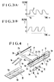
- Figs. 3(A) and 3(B) are graphs showing different waveforms of a voltage applied to the piezoelectric element 12 by the driving circuit 18.
- Fig. 3(A) shows the waveform of a voltage which is applied to the piezoelectric element 12 in order to move the lens barrel 1 in a rightward direction as viewed in Fig. 1.
- Fig. 3(B) shows the waveform of a voltage which is applied to the piezoelectric element 12 in order to move the lens barrel 1 in a leftward direction as viewed in Fig. 1.
- the piezoelectric element 12 When a driving pulse such as that shown in Fig. 3(A) is applied to the piezoelectric element 12, the piezoelectric element 12 rapidly expands at a vertical rising edge B of the driving pulse at which this pulse changes from a voltage A to a voltage C. At this time, the driving rod 17 is made to move in the leftward direction as viewed in Fig. 1 by an amount equivalent to the amount of expansion of the piezoelectric element 12. In this case, the lens barrel 1 does not move because the sum of the inertia of the lens barrel 1, the friction between the guide bar 3 and the inner surface of the U-shaped groove 1f and the like of the lens barrel 1 is greater than the driving force obtainable from the piezoelectric element 12.
- the piezoelectric element 12 slowly contracts and the lens barrel 1 is made to move in the rightward direction as viewed in Fig. 1 by the frictional force between the lens barrel 1 and the driving rod 17 and by the frictional force between the leaf spring 14 and the driving rod 17.
- the rightward movement of the driving rod 17 as viewed in Fig. 1 comes to a stop.
- the lens barrel 1 continues to move in the rightward direction as viewed in Fig. 1 by the kinetic energy of the lens barrel 1.
- the lens barrel 1 comes to a stop by the friction between the lens barrel 1 and the driving rod 17, the friction between the leaf spring 14 and the driving rod 17, and the like.
- the above-described motion is repeated by the application of each driving pulse so that the lens barrel 1 is driven to move in the rightward direction as viewed in Fig. 1.
- the position of the lens barrel 1 which is in progressive movement is detected sequentially in time by the position detector 19 consisting of the slidable contact piece 9 and the fixed detecting plate 10, and the output of the position detector 19 is fed back to the microcomputer 20.
- the microcomputer 20 causes the driving circuit 18 to stop driving the piezoelectric element 12.
- the microcomputer 20 controls the driving circuit 18 to apply a driving pulse such as that shown in Fig. 3(B) to the piezoelectric element 12.
- the driving pulse applied to the piezoelectric element 12 has a gradual rising edge and a vertical falling edge as shown in Fig. 3(B), so that the operation of the piezoelectric element 12 and that of the lens barrel 1 are reversed. More specifically, at the rising edge of the driving pulse at which this pulse slowly changes from the voltage A to the voltage C, the piezoelectric element 12 slowly expands and, therefore, the lens barrel 1 is made to move integrally with the driving rod 17 in the leftward direction as viewed in Fig.
- the piezoelectric element 12 rapidly contracts at the falling edge of the driving pulse at which this pulse rapidly changes from the voltage C to the voltage A. Accordingly, the driving rod 17 is made to move in the rightward direction as viewed in Fig. 1.
- a rightward driving force is applied to the lens barrel 1 from the driving rod 17 by the friction between the lens barrel 1 and the driving rod 17 and by the friction between the driving rod 17 and the leaf spring 14.
- the lens barrel 1 is held in a stationary state by inertia due to the mass of the lens barrel 1 and by the friction between the lens barrel 1 and the guide bar 3. Accordingly, while a pulse train such as that shown in Fig. 3(B) is being applied to the piezoelectric element 12, the lens barrel 1 is made to move progressively in the leftward direction as viewed in Fig. 1 by the application of each pulse in the above-described manner of operation.
- Fig. 4 is a diagrammatic exploded perspective view showing a second embodiment of the present invention which is applied to a magnetic-head driving device for a still video camera.
- identical reference numerals are used to denote members which are substantially identical to those shown in Fig. 1, and description of the identical members is omitted unless required.
- the arrangement of a control system in the second embodiment shown in Fig. 4 is substantially identical to that of the control system in the first embodiment, and the control system of the second embodiment is arranged in a manner similar to that shown in Fig. 2. Accordingly, description of the control system is also omitted.
- Driving pulses applied to the piezoelectric element 12 are substantially identical to those shown in Figs. 3(A) and 3(B), and the operation of the second embodiment is also substantially identical to that of the first embodiment.
- a magnetic head 22 is secured to a head carriage 21.
- Projections 21a and 21b project from the left side edge of the head carriage 21 as viewed in Fig. 4, and holes 21c and 21d are formed to extend through the respective projections 21a and 21b, the driving rod 17 being inserted through the holes 21c and 21d.
- An arm 21e projects from the right side edge of the head carriage 21 as viewed in Fig. 4, and a U-shaped groove 21f is formed in the arm 21e, the guide bar 3 being inserted through the U-shaped groove 21f.
- the leaf spring 14 has the curved projection 14c at the middle part and the through-openings 14a and 14b in the opposite end portions.
- the leaf spring 14 is secured to the undersides of the respective projections 21a and 21b by screwing the screws 15 and 16 into the aforesaid holes through the through-openings 14a and 14b.
- the curved projection 14c of the leaf spring 14 is pressed in contact with the underside of the driving rod 17 at a middle position between the projections 21a and 21b. Accordingly, the driving rod 17 is forced upwardly so that upper portions of the external surface of the driving rod 17 are pressed in contact with the respective upper portions of the inner surfaces of the holes 21c and 21d.
- the slidable contact piece 9 is mounted on the underside of the arm 21e with an electrically insulating sheet interposed therebetween.
- the slidable contact piece 9 and the fixed detecting plate 10 disposed below the path of movement of the head carriage 21 constitute the position detector 19 (refer to Fig. 2) for detecting the position of the head carriage 21 which is in progressive movement.
- the piezoelectric element 12 and the driving-rod supporting member 13 are substantially identical to those explained in connection with the first embodiment.
- the operation of the head carriage 21 and that of its associated control system are also substantially identical to those explained in connection with the first embodiment.
- a potentiometer-type position detector is used to detect the position of a driven member, such as the lens barrel 1 or the head carriage 21, which progressively varies with time.
- a non-contact detector may also be used to detect such a position.
- the driving device since the driving device according to either of the first and second embodiments employs a piezoelectric element as a driving source, it is not necessary to incorporate a motor, a speed reduction mechanism, a cam or a feed screw. Accordingly, it is possible not only to greatly reduce the size and weight of the driving device compared with conventional driving devices but also to achieve more accurate positioning control than would be the case if such a conventional driving device were used. In addition, fabrication cost and assembly cost can be greatly reduced. Accordingly, in accordance with either of the first and second embodiments of the present invention, it is possible to solve problems inherent in the conventional driving devices.
- FIG. 7 A third embodiment of the present invention will be described below with reference to Figs. 7 and 8.
- identical reference numerals are used to denote members which are used in common to the first embodiment.
- a piezoelectric element 115 is secured to the rear end of the support plate 1h of the lens barrel 1, and a weight 116 is secured to the other end of the piezoelectric element 115.
- the weight 116 has a hole 116a which extends through the same in the axial direction thereof, and the driving rod 17 is inserted through the hole 116a.
- the weight 116 is fitted onto the driving rod 17 for axial movement relative to each other.
- the piezoelectric element 115 has a structure which expands and contracts in the longitudinal direction.
- the piezoelectric element 115 is connected to the driving circuit 18 shown in Fig. 8 via the lead wires W1 and W2 leading from the piezoelectric element 115, and is driven to expand or contract in either of the directions indicated by an arrow f by a pulse voltage applied from the driving circuit 18.
- microcomputer 20 The operation of the microcomputer 20 is similar to that shown in the flowchart of Fig. 6, and the waveforms of the voltage applied to the piezoelectric element 115 are identical to those shown in Figs. 3(A) and 3(B).
- the piezoelectric element 115 When a driving pulse such as that shown in Fig. 3(A) is applied to the piezoelectric element 115, the piezoelectric element 115 rapidly expands at the vertical rising edge of the driving pulse at which this pulse changes from the voltage A to the voltage C. At this time, the lens barrel 1 and the weight 116 are made to move leftwardly and rightwardly as viewed in Fig.
- the piezoelectric element 115 slowly contracts at the falling edge of the driving pulse during which this pulse slowly changes from the voltage C to the voltage A.
- the lens barrel 1 is held in a stationary state by the frictional resistance among the lens barrel 1, the driving rod 17 and the guide bar 3 and by the frictional resistance between the leaf spring 14 and the driving rod 17, while the weight 116 alone is made to move in the leftward direction as viewed in Fig. 7.
- the lens barrel 1, the piezoelectric element 115 and the weight 116 start to move integrally in the leftward direction as viewed in Fig.
- a driving pulse such as that shown in Fig. 3(B) is applied to the piezoelectric element 115.
- the piezoelectric element 115 slowly expands.
- the lens barrel 1 is held in a stationary state by the frictional resistance between the lens barrel 1 and the driving rod 17, by the frictional resistance between the lens barrel 1 and the guide bar 3 and by the frictional resistance between the leaf spring 14 and the driving rod 17, while the weight 116 alone is made to move in the rightward direction as viewed in Fig. 7.
- the lens barrel 1, the piezoelectric element 115 and the weight 116 start to move integrally in the rightward direction as viewed in Fig. 7 by the kinetic energy of the weight 116.
- the kinetic energy of the weight 116 is consumed by the friction between each of the aforesaid portions, the motions of the lens barrel 1, the piezoelectric element 115 and the weight 116 come to a stop.
- the piezoelectric element 115 rapidly contracts at the falling edge of the driving pulse at which this pulse rapidly changes from the voltage C to the voltage A.
- the lens barrel 1 and the weight 116 are made to move rightwardly and leftwardly as viewed in Fig. 1, respectively, by an amount determined by the inertia mass of the lens barrel 1, the inertia mass of the weight 116, and the frictional resistance between each of the aforesaid portions.
- a potentiometer-type position detector is used to detect the position of a driven member, i.e., the lens barrel 1, which is in progressive movement.
- a non-contact detector may also be used to detect such a position.
- the driving device according to the third embodiment employs a piezoelectric element secured to a weight as a driving source, it is not necessary to incorporate a motor, a speed reduction mechanism or a cam. Accordingly, it is possible not only to greatly reduce the size and weight of the driving device compared with conventional driving devices but also to achieve more accurate positioning control than would be the case if such a conventional driving device were used. In addition, fabrication cost and assembly cost can be greatly reduced. Accordingly, in accordance with the third embodiment of the present invention, it is possible to solve problems inherent in the conventional driving devices.
- the control system of a driving device is substantially identical to that shown in Fig. 8, and a diagrammatic illustration of the control system is omitted.
- the waveforms of driving pulses applied to a piezoelectric element are similar to those shown in Figs. 3(A) and 3(B), and an illustration thereof is omitted.
- the flowchart showing the operation of a microcomputer is also omitted since it is similar to the flowchart of Fig. 6.
- one end of the piezoelectric element 115 is secured to the rear end of the support plate 1h of the lens barrel 1.
- the piezoelectric element 115 is secured in the vicinity of the guide bar 2 so that the rotational force of the lens barrel 1 can become small in a plane parallel to the guide bar 2, i.e., so that the lens barrel 1 can smoothly move along the guide bar 2.
- the weight 116 is secured to the other end of the piezoelectric element 115.
- the piezoelectric element 115 is connected to the driving circuit 18 of Fig. 8 by the lead wires W1 and W2, and is driven by a pulse voltage applied from the driving circuit 18 to expand or contract in either of the directions indicated by the arrow f.
- the leaf spring 14 has a through-opening 14a corresponding to the threaded hole of the projection 1a and a through-opening 14b corresponding to the threaded hole of the projection 1c, as well as the curved projection 14c which is formed so as to be pressed in contact with the underside of the guide bar 2 at an intermediate position between the projections 1a and 1c.
- the guide bar 2 When the leaf spring 14 is fixed to the undersides of the projections 1a and 1c, the guide bar 2 is relatively forced up with respect to the lens barrel 1, so that the guide bar 2 is elastically pressed in contact with upper portions of the inner surfaces of the respective holes 1b and 1d. Thus, the lens barrel 1 and the guide bar 2 are frictionally engaged with each other.
- the piezoelectric element 115 When a driving pulse such as that shown in Fig. 3(A) is applied to the piezoelectric element 115, the piezoelectric element 115 rapidly expands at the vertical rising edge of the driving pulse at which this pulse changes from the voltage A to the voltage C. At this time, the lens barrel 1 and the weight 116 are made to move in the leftward direction and in the rightward direction as viewed in Fig.
- the piezoelectric element 115 slowly contracts at the falling edge of the driving pulse during which this pulse slowly changes from the voltage C to the voltage A.
- the lens barrel 1 is held in a stationary state by the frictional resistance between the lens barrel 1 and the guide bars 2 and 3 and by the frictional resistance between the leaf spring 14 and the guide bar 2, while the weight 116 alone is made to move in the leftward direction as viewed in Fig. 9.
- the lens barrel 1, the piezoelectric element 115 and the weight 116 start to move integrally in the leftward direction as viewed in Fig.
- a driving pulse such as that shown in Fig. 3(B) is applied to the piezoelectric element 115.
- the piezoelectric element 115 slowly expands.
- the lens barrel 1 is held in a stationary state by the frictional resistance between the lens barrel 1 and the guide bar 2, by the frictional resistance between the lens barrel 1 and the guide bar 3 and by the frictional resistance between the leaf spring 14 and the guide bar 2, while the weight 116 alone is made to move in the rightward direction as viewed in Fig. 9.
- the lens barrel 1, the piezoelectric element 115 and the weight 116 start to move integrally in the rightward direction as viewed in Fig. 9 by the kinetic energy of the weight 116.
- the kinetic energy of the weight 116 is consumed by the friction between each of the aforesaid, the motions of the lens barrel 1, the piezoelectric element 115 and the weight 116 come to a stop.
- the piezoelectric element 115 rapidly contracts at the falling edge of the driving pulse at which this pulse rapidly changes from the voltage C to the voltage A.
- the lens barrel 1 and the weight 116 are made to move rightwardly and leftwardly as viewed in Fig. 1, respectively, by an amount determined by the inertia mass of the lens barrel 1, the inertia mass of the weight 116, and the frictional resistance between each of the aforesaid portions.
- Fig. 10 is a diagrammatic exploded perspective view of a fifth embodiment of the present invention.
- the fifth embodiment is substantially identical to the fourth embodiment except that a ring-shaped piezoelectric element 120 and a ring-shaped weight 121 are employed.
- a front end face 120a of the piezoelectric element 120 is secured to the rear end face of the lens barrel 1, and the weight 121 is secured to a rear end face 120b of the piezoelectric element 120.
- the ring-shaped piezoelectric element 120 is used as in the case of the fifth embodiment, the area of contact between the piezoelectric element 120 and the lens barrel 1 becomes large and, therefore, a large driving force can be obtained.
- the area of adhesion between the lens barrel 1 and the piezoelectric element 120 is also large, it is possible to reduce the possibility that the piezoelectric element 120 will come off by the application of a large impact or the like.
- the arrangement of a control system in the fifth embodiment is substantially identical to that of the control system in the fourth embodiment, and the waveforms of driving pulses applied to the piezoelectric element 120 and the operation of the entire device are also substantially identical to those explained in connection with the fourth embodiment. Therefore, description is omitted.
- a potentiometer-type position detector is used to detect the position of a driven member, such as the lens barrel 1 or the head carriage 21, which is in progressive movement.
- a non-contact detector may also be used to detect such a position.
- the driving device since the driving device according to either of the fourth and fifth embodiments employs a piezoelectric element as a driving source and the piezoelectric element is brought into direct contact with a lens barrel, it is not necessary to incorporate a motor, a speed reduction mechanism, a cam or the like. Accordingly, it is possible not only to greatly reduce the size and weight of the driving device compared with conventional driving devices but also to achieve more accurate positioning control than would be the case if such a conventional driving device were used. In addition, fabrication cost and assembly cost can be greatly reduced.
- Fig. 11 is a diagrammatic exploded perspective view showing a sixth embodiment of the present invention.
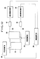
- Fig. 12 is a schematic block diagram showing primary parts of a system according to the sixth embodiment.
- a lens barrel 201 is slidably fitted onto a shaft 202 by means of holes 201b and 201d.
- the shaft 202 which is disposed to extend along the optical axis, is fixed at one end to a piezoelectric element 212, as by an adhesive.
- a support member 213 is secured to a fixed portion (not shown) within a lens unit (not shown), and holes 213b and 213d are respectively formed in upright portions 213a and 213c of the support member 213.
- the shaft 202 is supported for sliding movement through the holes 213b and 213d.
- the piezoelectric element 212 expands and contracts in the longitudinal direction by the application of a voltage through lead wires 212a and 212b.
- the shaft 202 is secured to one end of the piezoelectric element 212 relative to the directions of expansion and contraction thereof, while the other end of the piezoelectric element 212 is secured to an upright portion 213e of the support member 213.
- a leaf spring 214 has a curved projection 214c of U-like cross section at its lengthwise mid portion and through-openings 214a and 214b at its lengthwise opposite end portions.
- the leaf spring 214 is secured to projections 201a and 201c of the lens barrel 201 by screws 215 and 216 inserted through the respective through-openings 214a and 214b, and the curved projection 214c is elastically pressed against the shaft 202.
- the leaf spring 214 acts to bias the shaft 202 in the holes 201b and 201d, thereby producing frictional forces between the inner surface of the hole 201b and the shaft 202, between the inner surface of the hole 201c and the shaft 202, and between the curved projection 214c and the shaft 202.
- a brush 209 which serves as a slidable contact piece is secured to the reverse side of an arm 201e, as viewed in Fig. 11, with an electrical insulator 211 interposed therebetween.
- the brush 209 has bent portions 209d and 209e which are respectively arranged for sliding movement over a conductor part 210a and a resistor part 210b provided on a resistor board 210 secured to the fixed member within the lens unit.
- a lens barrel 225 is slidably fitted onto a shaft 203 by means of holes 225b and 225d.
- the shaft 203 which is disposed to extend along the optical axis, is fixed at one end to a piezoelectric element 217.
- a support member 218 is secured to the fixed portion within the lens unit, and holes 218b and 218d are respectively formed in upright portions 218a and 218c of the support member 218.
- the shaft 203 is supported for sliding movement through the holes 218b and 218d.
- the piezoelectric element 217 expands and contracts in the longitudinal direction by the application of a voltage through lead wires 217a and 217b.
- the shaft 203 is secured to one end of the piezoelectric element 217 relative to the directions of expansion and contraction thereof, while the other end of the piezoelectric element 217 is secured to an upright portion 218e of the support member 218.
- a leaf spring 219 has a configuration similar to that of the leaf spring 214, and is secured to projections 225a and 225c of the lens barrel 225 by screws 220 and 221 inserted through respective through-openings 219a and 219b. Thus, the curved projection 219c is elastically pressed against the shaft 203.
- the leaf spring 219 acts to bias the shaft 203 in the holes 225b and 225d, thereby producing frictional forces between the inner surface of the hole 225b and the shaft 203, between the inner surface of the hole 225c and the shaft 203, and between the curved projection 219c and the shaft 203.
- a brush 224 which serves as a slidable contact piece is secured to the reverse side of an arm 225e, as viewed in Fig. 11, with an electrical insulator 223 interposed therebetween.
- the brush 224 has bent portions 224d and 224e which are respectively arranged for sliding movement over a conductor part 222a and a resistor part 222b provided on a resistor board 222 secured to the fixed member within the lens unit.
- a microcomputer 226 constitutes a system controller in an imaging apparatus such as a camera, and outputs to lens driving circuits 227 and 228 approximately sawtooth-shaped driving pulses such as those shown in Figs. 3(A) and 3(B).
- the lens driving circuits 227 and 228 receive driving pulses of about 5V from the microcomputer 226 and output driving pulses, such as those shown in Figs. 3(A) and 3(B), of the order of some tens of volts up to one hundred volts which are required to drive the piezoelectric elements 212 and 217.
- a potentiometer 229 practically consists of the brush 209 and the resistor board 210 which are shown in Fig. 11, while a potentiometer 230 practically consists of the brush 224 and the resistor board 222 which are shown in Fig. 11.
- Fig. 3(A) shows a driving waveform for use in driving the lens barrel 201 in the rightward direction as viewed in Fig. 11.
- Fig. 3(B) shows a driving waveform for use in driving the lens barrel 201 in the leftward direction as viewed in Fig. 11.
- the vertical axis and the horizontal axis represent voltage and time, respectively.
- the piezoelectric element 212 is supplied with a driving voltage, such as that shown in Fig. 3(A), through the lead wires 212a and 212b, the driving voltage changes from the predetermined voltage A to the predetermined voltage C which is higher than the voltage A.
- the rise B of the driving voltage is of extremely short duration, so that the piezoelectric element 212 rapidly expands in the longitudinal direction.
- the shaft 202 is also made to move rapidly in the leftward direction as viewed in Fig. 11 by an amount equivalent to the amount of expansion of the piezoelectric element 212.
- the rapid leftward movement of the shaft 202 acts to move the lens barrel 201 in the leftward direction as viewed in Fig.
- the lens barrel 201 (which is hereinafter assumed to include an internally fixed lens) remains stationary due to the inertia of the mass of its own.
- the driving voltage changes from the voltage C to the voltage A.
- the fall D has long duration compared with the rise B. Accordingly, as the shaft 202 is made to move rightwardly as viewed in Fig. 11 with the contraction of the piezoelectric element 212, the lens barrel 201 is made to move rightwardly as viewed in Fig. 11 by the frictional force between the lens barrel 201 and the shaft 202 and the frictional force between the leaf spring 214 and the shaft 202. Then, at the time when the contraction of the piezoelectric element 212 is completed, i.e., at the time when the driving voltage returns to the voltage A, the rightward movement of the shaft 202 rapidly comes to a stop.
- the lens barrel 201 continues to move rightwardly as viewed in Fig. 11, and comes to a stop until the aforesaid kinetic energy is consumed by the friction between the lens barrel 201 and the shaft 202 and the friction between the leaf spring 214 and the shaft 202.
- the shaft 202 comes to a stop, but the lens barrel 201 continues to move until kinetic energy is consumed by the friction between the lens barrel 201 and the shaft 202 and the friction between the leaf spring 214 and the shaft 202.
- the piezoelectric element 212 contracts and the shaft 202 is made to move in the rightward direction as viewed in Fig. 11.
- This motion acts to cause the lens barrel 201 to move rightwardly as viewed in Fig. 11 by the friction between the shaft 202 and the lens barrel 201 and the friction between the shaft 202 and the leaf spring 214, but the lens barrel 201 is held in a stationary state by the inertia of the mass of its own.
- the lens barrel 201 is made to move leftwardly as viewed in Fig. 11 by repeating the above-described driving.
- the lens barrel 201 is rectilinearly guided by the shaft 202, but is inhibited from rotating about the shaft 202 by the shaft 203.
- the shaft 203 is, as described later, displaced in the axial direction so that the lens barrel 225 can be made to move by the piezoelectric element 217.
- the displacement of the shaft 203 does not influence the displacement of the lens barrel 201 because the friction between the shaft 203 and a groove 201f of U-shaped cross section of the lens barrel 201 is kept extremely small by the friction between the leaf spring 214 and the shaft 202 and the friction between the shaft 202 and the inner surfaces of the holes 201b and 201d of the lens barrel 201.
- a driving mechanism for the lens barrel 225 is similar to the above-described driving mechanism for the lens barrel 201. Accordingly, the lens barrel 225 can be made to move rightwardly or leftwardly as viewed in Fig. 11 by applying a voltage of the waveform shown in Fig. 3(A) or 3(B) to the piezoelectric element 217.
- the shafts 202 and 203 for rectilinearly guiding the respective lens barrels 201 and 225 are axially displaced by the associated piezoelectric elements 212 and 217, but driving force can be selectively transmitted by selectively coupling the respective lens barrels 201 and 225 to the shafts 202 and 203 by frictional force.
- a driven member axially moves along a guide member which is being made to move back and forth by the application of an electric field to an electrical-mechanical energy converting element, for example, a piezoelectric element.
- an electrical-mechanical energy converting element for example, a piezoelectric element.
- a driving mechanism according to the present invention is applied to a head driving device.
- a head carriage which is one constituent part for the head driving device is denoted by 308, and the head carriage 308 has two projections 308a and 308b on one side and one projection 308c on another side.
- Holes 308d and 308e are formed to extend through the respective projections 308a and 308b, and a first guide bar 303 is relatively slidably inserted into the holes 308d and 308e.
- a groove 308f of U-shaped cross section is formed in the end portion of the projection 308c, and a second guide bar 305 is relatively slidably inserted through the groove 308f.
- a piezoelectric element 309 which is elongated in a direction parallel to the guide bars 303 and 305 is secured at its one end to the rear end face of the head carriage 308, and a weight 310 is secured to the other end of the piezoelectric element 309.
- the piezoelectric element 309 is of a type which expands parallel to its own longitudinal axis by the application of a voltage, and the driving circuit 316 shown in Fig. 14 is electrically connected to the piezoelectric element 309.
- a recess 308g is formed in the head carriage 308 in the vicinity of the front end thereof (the left end as viewed in Fig. 13), and a light emitting element 311 which has a bottom face serving as a light emitting face is disposed in the recess 308g.
- a slit 308h which is elongated in a direction perpendicular to the guide bars 303 and 305 (that is, in a direction perpendicular to the direction of movement of the head carriage 308), is formed in the bottom of the recess 308g to extend therethrough. Light emitted from the light emitting element 311 passes through the slit 308h and is projected downwardly from the head carriage 308 as a narrow beam of light.
- a semiconductor position detecting element 312 having a rectangular shape which is elongated in a direction parallel to the direction of movement of the head carriage 308 is secured to a fixed member (not shown) immediately below the path of movement of the head carriage 308.
- the semiconductor position detecting element 312 is electrically connected to the driving circuit 316 shown in Fig. 14.
- a leaf spring 313 extends parallel to the guide bar 303 between the projections 308a and 308b.
- the leaf spring 313 has through-openings 313a and 313b which are respectively formed in its opposite end portions, and is mounted on the undersides of the respective projections 308a and 308b by screwing screws 314 and 315 into the respective threaded holes which are in alignment with the through-openings 313a and 313b.
- a curved projection 313c to be elastically pressed in contact with the underside of the guide bar 303 is formed at the middle of the leaf spring 313.
- Fig. 14 is a schematic block diagram showing a control system for controlling the movement and positioning of the head carriage 308.
- a driving circuit 316 applies a sawtooth driving pulse as high as some tens of volts up to one hundred volts, such as that shown in Fig. 3(A) or 3(B), to the piezoelectric element 309.
- the driving circuit 316 is driven by an about 5V driving pulse of the same waveform which is applied from a microcomputer 317.
- the piezoelectric element 309 rapidly expands at the vertical rising edge of the driving pulse.
- the head carriage 308 is made to slide on the guide bar 303 because a force which is generated from the piezoelectric element 309 in the direction of expansion thereof is greater than the mutual frictional force between the guide bar 303 and the inner surfaces of the holes 308d and 308e of the head carriage 308.
- the piezoelectric element 309 slowly contracts, so that the head carriage 308 remains stationary because a force which acts in the direction of contraction at that time is less than the mutual frictional force between the guide bar 303 and the inner surfaces of the holes 308d and 308e of the head carriage 308.
- the head carriage 308 performs a fine inching motion by the expansion and contraction of the piezoelectric element 309.
- the position of the moving head carriage 308 and the amount of movement thereof are detected by the semiconductor position detecting element 312 in the form of an electrical output which corresponds to the position of slit-shaped light (shown by a dashed line in Fig. 13) which is projected from the light emitting element 311 onto the semiconductor position detecting element 312 through the slit 308h.
- the output from the semiconductor position detecting element 312 is inputted to the microcomputer 317, which controls the driving circuit 316.
- Fig. 3(A) shows the waveform of a driving pulse which is applied to the piezoelectric element 309 in order to move the head carriage 308 in the leftward direction as viewed in Fig. 13.
- Fig. 3(B) shows the waveform of a driving pulse which is applied to the piezoelectric element 309 in order to move the head carriage 308 in the rightward direction as viewed in Fig. 13.
- the piezoelectric element 309 When a driving pulse such as that shown in Fig. 3(A) is applied to the piezoelectric element 309, the piezoelectric element 309 rapidly expands at the vertical rising edge of the driving pulse at which this pulse changes from the voltage A to the voltage C.
- the head carriage 308 is subjected to a leftward driving force which is greater than the sum of inertia force based on the mass of the head carriage 308, the friction between the guide bar 303 and the inner surfaces of the holes 308d and 308e of the head carriage 308, the friction between the guide bar 305 and the inner surface of the groove 308f, the friction between the guide bar 303 and the curved projection 313c of the leaf spring 313, and the like. Accordingly, as viewed in Fig.
- the head carriage 308 is made to move leftwardly by a small amount, while the weight 310 is made to move rightwardly by a small amount.
- the driving pulse is maintained at its maximum level (voltage C)
- the piezoelectric element 309 is held in an expanded state. Then, the piezoelectric element 309 contracts at the falling edge D of the driving pulse during which this pulse non-vertically changes from the voltage C to the voltage A.
- a force resulting from the contraction of the piezoelectric element 309 is less than the sum of inertia force of the head carriage 308, the frictional force between the guide bar 303 and the curved projection 313c of the leaf spring 313, the frictional force between the guide bar 303 and the inner surfaces of the holes 308d and 308e of the head carriage 308, the frictional force between the guide bar 305 and the inner surface of the groove 308f, and the like. Accordingly, the head carriage 308 comes to a stop, and the weight 310 alone is made to move leftwardly as viewed in Fig. 13 with the contraction of the piezoelectric element 309.
- the head carriage 308 At the time when the contraction of the piezoelectric element 309 is completed, i.e., at the time when the driving pulse returns to the voltage A, the head carriage 308, the piezoelectric element 309 and the weight 310 are made to move integrally in the leftward direction by the leftward kinetic energy of the weight 310. When such energy is consumed, the head carriage 308 comes to a stop.
- the above-described operation is repeated by the application of each driving pulse, whereby the head carriage 308 is made to move leftwardly by a predetermined small amount at a time.
- the amount of movement of the head carriage 308 and the instantaneous position thereof which varies with the movement are, as described above, detected by the semiconductor position detecting element 312 and fed back to the microcomputer 317. Accordingly, when the head carriage 308 is made to move to a predetermined position, the application of the driving pulse to the piezoelectric element 309 is stopped by the microcomputer 317.
- the microcomputer 317 causes the driving circuit 316 to apply a driving pulse such as that shown in Fig. 3(B) to the piezoelectric element 309. More specifically, when a voltage which non-vertically rises from the voltage A to the voltage C is applied to the piezoelectric element 309, the piezoelectric element 309 starts to expand slowly. The force of this expansion is smaller than the sum of the inertia force of the head carriage 308 and the frictional forces occurring at the aforesaid portions.
- the head carriage 308 is held in a stationary state and the weight 310 alone is made to move rightwardly as viewed in Fig. 13 with the expansion of the piezoelectric element 309. Then, at the time when the expansion of the piezoelectric element 309 is completed, the head carriage 308, the piezoelectric element 309 and the weight 310 start to move integrally in the rightward direction as viewed in Fig. 13 by the kinetic energy of the weight 310. When the kinetic energy is consumed by the frictions occurring at the above-described portions, the head carriage 308 and the weight 310 come to a stop.
- the piezoelectric element 309 rapidly contracts, whereby the head carriage 308 is made to move in the rightward direction as viewed in Fig. 13, while the weight 310 is made to move in the leftward direction.
- the above-described operation is repeated by the application of each driving pulse, whereby the head carriage 308 is made to move progressively in the rightward direction as viewed in Fig. 13.
- light from the light emitting element 311 mounted on the head carriage 308 is projected onto the semiconductor position detecting element 312 through the slit 308h.
- the slit-shaped light projected on the semiconductor position detecting element 312 moves thereon with the movement of the head carriage 308, the instantaneous position of the head carriage 308 which varies with the movement is detected by the semiconductor position detecting element 312 and the output therefrom is fed back to the microcomputer 317, whereby the amount of movement of the head carriage 308 and the stop position thereof are controlled.
- the semiconductor position detecting element 312 is used to detect the instantaneous position of the head carriage 308, a different detecting means such as a linear encoder or a potentiometer may, of course, be employed in place of the element 312.
- the curved projection 313c of U-shaped cross section is formed at the middle of the leaf spring 313 so that the elastic force of the leaf spring 313 can be applied to the guide bar 303 approximately perpendicularly.
- the leaf spring 313 has flat portions 313d and 313e which extend parallel to the directions of expansion and contraction of the piezoelectric element 309, and is formed to have a high rigidity in these directions.
- Other examples of this leaf spring are shown in Figs. 15(A), 15(B), 15(C) and 16.
- a leaf spring 318 of flat shape has holes 318a and 318b for securing the leaf spring 318 to the projections 308a and 308b of the head carriage 308.
- a frictional member 319 is formed of a material, such as metal or resin, which has a high rigidity at least in the directions of expansion and contraction of the piezoelectric element 309. The frictional member 319 is secured to the middle of the leaf spring 318.
- the leaf spring 313 in the embodiment shown in Fig. 13 exhibits more or less spring properties at the upward rising portion of the curved projection 313c
- the example of Fig. 15(A) exhibits a higher rigidity than the leaf spring 313 in the directions of expansion and contraction of the piezoelectric element 309.
- Fig. 15(B) shows a leaf spring which facilitates adjustment of frictional force.
- a leaf spring 320 has a hole 320a and a slot 320b for securing the leaf spring 320 to the projections 308a and 308b of the head carriage 308 by means of the respective screws 314 and 315.
- Fig. 16 is a diagrammatic view showing the assembled state of the leaf spring 320. The leaf spring 320 is tightly secured to the projection 308a by the screw 314 at the position of the hole 320a. The frictional member 319 is pressed against the guide bar 303 by the leaf spring 320.
- the screw 315 is screwed into the projection 308b through the slot 320b, and the tightening strength of the screw 315 can be adjusted to change the state of bend of the leaf spring 320, thereby adjusting the pressure of an elastic member against the guide bar 303. After this adjustment has been performed, the screw 315 is fixed by an adhesive.
- Fig. 15(C) shows a leaf spring 321 having one flat portion to which the frictional member 319 is secured.
- the leaf spring 321 is secured to the projection 308a by the screw 314 passed through a hole 321a.
- Fig. 17 is a schematic cross-sectional view showing an eighth embodiment
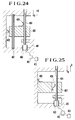
- Figs. 22 and 23 are diagrams showing different waveforms of a voltage applied to a piezoelectric element.
- reference numeral 401 denotes a fixed portion consisting of, for example, a frame
- reference numeral 404 denotes a vibration shaft which is longitudinally movably supported and guided by the fixed portion 401
- reference numeral 402 denotes a movable object having mass.
- the movable object 402 is supported and guided by the vibration shaft 404 and the fixed portion 401 with the direction of movement of the movable object 402 restricted by them.
- a piezoelectric element 403 is held by the fixed portion 401 in such a manner that the directions of expansion and contraction (lamination direction) of the piezoelectric element 403 coincide with the directions indicated by arrows A and B of Fig. 17.
- One end face of the piezoelectric element 403 relative to the directions of expansion and contraction of the piezoelectric element 403 abuts against one end of the vibration shaft 404, and the piezoelectric element 403 and the vibration shaft 404 are integrally bonded by an adhesive.
- a first leaf spring 405 is secured to the movable object 402 to urge the fixed portion 401 by a constant force, thereby producing a frictional force between the fixed portion 401 and the movable object 402.
- a second leaf spring 408 is secured to the movable object 402 to urge the vibration shaft 404 by a constant force, thereby producing a frictional force between the movable object 402 and the vibration shaft 404.
- the sum of the frictional forces produced by the leaf springs 405 and 408 are set to be greater than gravitational force acting on the movable object 402.
- the frictional force produced by the second leaf spring 408 is set to be greater than that produced by the first leaf spring 405.
- both the leaf springs 405 and 408 are used to impart frictional force to the movable object 402.
- reference numerals 410 and 411 denote different voltage waveforms which are applied for driving of a piezoelectric element.
- the voltage waveform 410 shown in Fig. 22 has a rapid voltage rise 410a and a relatively slow voltage drop 410b
- the voltage waveform 411 of Fig. 23 has a relatively slow voltage rise 411a and a rapid voltage drop 411b.
- a voltage waveform adjusting circuit 412 serves as a voltage controlling circuit, and is connected to a power source 413 and the piezoelectric element 403 by electric wires, respectively.
- the piezoelectric element 403 rapidly expands in the direction of the arrow A at the rapid voltage rise 410a and the vibration shaft 404 is also made to move in the direction of the arrow A by an amount equivalent to the expansion of the piezoelectric element 403.
- the movable object 402 hardly moves since it does not follow the movement of the vibration shaft 404 by the inertia of the movable object 402 due to the own weight thereof and by the frictional force produced by the first leaf spring 405.
- the piezoelectric element 403 slowly contracts in accordance with the voltage drop.
- the vibration shaft 404 is made to move slowly in the direction of the arrow B, and the movable object 402 is also made to move in the direction of the arrow B because the frictional force produced by the second leaf spring 408 is greater than that produced by the first leaf spring 405.
- the above-described sequence of operations is repeated and the movable object 402 is made to move in the direction of the arrow B.
- the piezoelectric element 403 slowly expands at the relatively slow voltage rise 411a in the direction of the arrow A as viewed in Fig. 17 in accordance with the voltage rise, and the vibration shaft 404 is also made to move in the direction of the arrow A.
- the movable object 402 moves together with the vibration shaft 404 in the direction of the arrow A owing to the frictional force produced by the second leaf spring 408.
- the piezoelectric element 404 rapidly contracts at the rapid voltage drop 411b and the vibration shaft 404 is made to move rapidly in the direction of the arrow B by an amount equivalent to the contraction of the piezoelectric element 403.
- the movable object 402 hardly moves since it does not follow the movement of the vibration shaft 404 by the inertia of the movable object 402 due to the own weight thereof and by the frictional force produced by the first leaf spring 405.
- the movable object 402 is made to move in the direction of the arrow A by the application of the voltage waveform shown in Fig. 23.
- the piezoelectric element 403 and the vibration shaft 404 are fixed to each other by the adhesive so that the movement of the vibration shaft 404 follows the expansion and contraction of the piezoelectric element 403.
- a coil spring 406 is provided on a side opposite to the piezoelectric element 403, and the vibration shaft 404 and the piezoelectric element 403 are maintained in contact with each other.
- the vibration shaft 404 is at all times pressed in contact with the piezoelectric element 403 by the spring force of the coil spring 406 so that the vibration shaft 404 is prevented from moving away from the piezoelectric element 403 by the expansion or contract of the piezoelectric element 403.
- Fig. 20 shows an embodiment consisting of a combination of the embodiments shown in Figs. 18 and 19.
- the movable object 402 is supported by the vibration shaft 404 which is inserted through the movable object 402. To obtain a similar effect, the movable object 402 may also be supported and guided by the guide shaft 407 and the fixed portion 401 as shown in Fig. 21.
- the first leaf spring 405 may be provided on the fixed portion 401 as shown in Fig. 24 and the second leaf spring 408 on the vibration shaft 404 as shown in Fig. 25. In this arrangement as well, a similar effect can be obtained.
- an elastic member such as a coil spring or a rubber may also be employed.
- an electrical-mechanical energy converting element for example a piezoelectric element
- a moving mechanism having an extremely simple structure whereby it is possible to provide a miniaturized moving mechanism.
- the amount of displacement of the piezoelectric element is extremely small at the application of a voltage, it is possible to position the movable object with extremely high accuracy.
- the movable object since the sum of the frictional forces produced by the leaf springs 405 and 408 is greater than gravitational force applied to the movable object, the movable object does not move down by its own weight even if the direction of the movement thereof is set to any direction.
- the moving mechanism according to each of the eighth to twelfth embodiments makes it possible to realize a desired amount of displacement and to effectively miniaturize the device.
- Fig. 26 is a diagrammatic view showing a moving mechanism according to a thirteenth embodiment of the present invention.
- reference numeral 501 denotes a fixed portion
- reference numeral 502 denotes a movable object
- reference numerals 503a and 503b denote piezoelectric elements.
- the piezoelectric elements 503a and 503b are held against the fixed portion 501 in such a manner that the direction of their expansion and contraction (their lamination directions) coincide with the directions indicated by the arrows A and B of Fig. 26.
- Both ends of a vibration shaft 504 are maintained in contact with the respective piezoelectric elements 503a and 503b, or they are opposed to the respective piezoelectric elements 503a and 503b with small gaps interposed therebetween.
- These gaps are selected to be smaller than the amounts of expansion of the respective piezoelectric elements 503a and 503b by the application of a voltage.
- the vibration shaft 504 is held by the fixed portion 501 for movement in the direction of each of the arrows A and B of Fig. 26.
- a guide shaft 505 is secured to the fixed portion 501, and serves to guide the axial movement of the movable object 502 while limiting the rotation of the movable object 502 about the vibration shaft 504.
- a leaf spring 506 is secured to the movable object 502, and urges the vibration shaft 504 with a constant spring force to produce a frictional force between the movable object 502 and the vibration shaft 504.
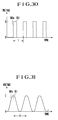
- a voltage waveform adjusting circuit 512 is arranged to convert a voltage from a power source 513 into a waveform 510 or 511 having a rapid voltage rise 510a or 511a as shown in Fig. 30 or 31 and apply such a waveform to the piezoelectric elements 503a and 503b. There is also provided a selecting circuit for selectively and alternately applying the waveforms 510 and 511 to the piezoelectric elements 503a and 503b.
- the piezoelectric element 503a rapidly expands in the direction of the arrow A as viewed in Fig. 26 to instantaneously impart a large acceleration (impact) to the vibration shaft 504 in the direction of the arrow A.
- the movable object 502 hardly moves since it does not follow the movement of the vibration shaft 504 owing to the inertia of the movable object 502 due to the own weight thereof. Then, as the voltage applied to the piezoelectric element 503a drops, the piezoelectric element 503a contracts and the vibration shaft 504 is made to return to its original position by a reaction to the impact imparted by the piezoelectric element 503a. During this time, the movable object 502 moves together with the vibration shaft 504 by a frictional force which is produced between the vibration shaft 504 and the movable object 502 by the leaf spring 506.
- the movable object 502 is made to move in the direction of the arrow B by a small amount. Subsequently, the movable object 502 is made to progressively move in the direction of the arrow B by repeating the above-described operation (cycle T).
- the movable object 502 is made to move in the opposite direction indicated by the arrow A.
- the impact which has been imparted to the vibration shaft 504 by one piezoelectric element is applied to the other piezoelectric element.
- stepped portions may be formed at the opposite end portions of the vibration shaft 504 and engaged with the fixed portion 501 so as to prevent the impact of the vibration shaft 504 from being applied to the other piezoelectric element.
- leaf spring 506 is provided on the movable object 502, it may also be provided on the vibration shaft 504 as shown in Fig. 28.
- Fig. 29 shows a moving mechanism consisting of a combination of the embodiments shown in Figs. 27 and 28.
- a leaf spring is used as friction means
- an elastic member such as a coil spring or a rubber, or a magnet may also be employed.
- a piezoelectric element can be employed to constitute a moving mechanism having an extremely simple structure. Accordingly, it is possible to provide a miniaturized moving mechanism and it is also possible to achieve, by the application of a voltage, a large amount of movement with respect to an extremely small amount of displacement of the piezoelectric element.
- the amount of displacement of the piezoelectric element is extremely small at the application of a voltage, it is possible to position the movable object with extremely high accuracy.
- Fig. 32 is a diagrammatic view showing a moving mechanism according to a seventeenth embodiment of the present invention.
- reference numeral 601 denotes a fixed portion
- reference numeral 602 denotes a movable object
- reference numerals 603a and 603b denote piezoelectric elements.
- the piezoelectric elements 603a and 603b are held against the fixed portion 601 in such a manner that the directions of their expansion and contraction (their lamination directions) coincide with the directions indicated by the arrows A and B of Fig. 32.
- Both ends of a vibration shaft 604 are maintained in contact with the respective piezoelectric elements 603a and 603b, or they are opposed to the respective piezoelectric elements 603a and 603b with small gaps interposed therebetween.
- These gaps are selected to be smaller than the amounts of expansion of the respective piezoelectric elements 603a and 603b by the application of a voltage.
- the vibration shaft 604 is held by the fixed portion 601 for movement in the direction of each of the arrows A and B of Fig. 32.
- a first leaf spring 605 is secured to the movable object 602, and urges the vibration shaft 604 with a constant spring force to produce a frictional force between the movable object 602 and the vibration shaft 604.
- a second leaf spring 606 is secured to the movable object 602, and urges the fixed portion 601 with a constant spring force to produce a frictional force between the movable object 602 and the fixed portion 601.
- the resultant of the frictional forces produced by the first and second leaf springs 605 and 606 are set to be greater than gravitational force acting on the movable object 602.
- the movable object 602 can be made to move, and if the frictional force produced by the first leaf spring 605 is made greater than the gravitational force applied to the movable object 602, it is also possible to prevent the movable object 602 from moving down by its own weight. In this arrangement, however, the frictional force by the first leaf spring 605 becomes excessively large with respect to the mass of the movable object 602, thus lowering the speed of movement of the movable object 602. Accordingly, in this embodiment, the first and second leaf springs 605 and 606 are used to impart frictional force to the movable object 602.
- a voltage waveform adjusting circuit 612 is arranged to convert a voltage from a power source 613 into a waveform 610 or 611 having a rapid voltage rise 610a or 611a as shown in Fig. 37 or 38 and apply such a waveform to the piezoelectric elements 603a and 603b.
- a selecting circuit for selectively and alternately applying the waveforms 610 and 611 to the piezoelectric elements 603a and 603b.
- the piezoelectric element 603a rapidly expands in the direction of the arrow A as viewed in Fig. 32 to instantaneously impart a large acceleration (impact) to the vibration shaft 604 in the direction of the arrow A.
- the movable object 602 hardly moves since it does not follow the movement of the vibration shaft 604 owing to the inertia of the movable object 602 due to the own weight thereof. Then, as the voltage applied to the piezoelectric element 603a drops, the piezoelectric element 603a contracts and the vibration shaft 604 is made to return to its original position by a reaction to the impact imparted by the piezoelectric element 603b. During this time, the movable object 602 moves together with the vibration shaft 604 since a frictional force which is produced between the vibration shaft 604 and the movable object 602 by the first leaf spring 605 is greater than a frictional force produced by the second leaf spring 606.
- the movable object 602 is made to move in the direction of the arrow B by a small amount. Subsequently, the movable object 602 is made to progressively move in the direction of the arrow B by repeating the above-described operation (cycle T).
- the movable object 602 is made to move in the opposite direction indicated by the arrow A.
- stepped portions may be formed at the opposite end portions of the vibration shaft 604 and engaged with the fixed portion 601 so as to prevent the impact of the vibration shaft 604 from being applied to the other piezoelectric element.
- the second leaf spring 606 is provided on the moving object 602, it may also be provided on the fixed portion 601 as shown in Fig. 34 or on both the moving object 602 and the fixed portion 601.
- the first leaf spring 605 is provided on the moving object 602, it may also be provided on the vibration shaft 604 as shown in Fig. 35 or on both the moving object 602 and the vibration shaft 604.
- the movable object 602 may be fitted onto a guide shaft 607 alone and a frictional force may be produced between the movable object 602 and the vibration shaft 604 by the first leaf spring 605 provided on the vibration shaft 604.
- a leaf spring is used as friction means
- an elastic member such as a coil spring or a rubber, or a magnet may also be employed.
- a piezoelectric element can be employed to constitute a moving mechanism having an extremely simple structure. Accordingly, it is possible to provide a miniaturized moving mechanism and it is also possible to achieve, by the application of a voltage, a large amount of movement with respect to an extremely small amount of displacement of the piezoelectric element.
- the amount of displacement of the piezoelectric element is extremely small at the application of a voltage, it is possible to position the movable object with extremely high accuracy.
- first and second friction means consisting of leaf springs or the like
- gravitational force applied to the movable object it is possible to prevent the movable object from moving down by its own weight even if the direction of movement of the movable object is set to any direction.
- a driving device includes a driving member which is frictionally engaged with a driven member or a member coupled to the driven member and which is movably supported on a fixed member, a piezoelectric element disposed in contact with the driving member, and a driving circuit for applying a voltage to the piezoelectric element so as to make the speed of expansion of the piezoelectric element different from the speed of contraction thereof.
Landscapes
- Engineering & Computer Science (AREA)
- Mechanical Engineering (AREA)
- Physics & Mathematics (AREA)
- General Physics & Mathematics (AREA)
- Optics & Photonics (AREA)
- General Electrical Machinery Utilizing Piezoelectricity, Electrostriction Or Magnetostriction (AREA)
- Lens Barrels (AREA)
Applications Claiming Priority (18)
| Application Number | Priority Date | Filing Date | Title |
|---|---|---|---|
| JP175544/90 | 1990-07-03 | ||
| JP175545/90 | 1990-07-03 | ||
| JP17554690A JPH0463309A (ja) | 1990-07-03 | 1990-07-03 | レンズ駆動装置 |
| JP2175544A JP2633066B2 (ja) | 1990-07-03 | 1990-07-03 | 駆動装置 |
| JP2175545A JP2625567B2 (ja) | 1990-07-03 | 1990-07-03 | 駆動装置 |
| JP175546/90 | 1990-07-03 | ||
| JP2271962A JPH04147107A (ja) | 1990-10-09 | 1990-10-09 | 駆動機構を有する機器 |
| JP271959/90 | 1990-10-09 | ||
| JP27195990A JPH04147474A (ja) | 1990-10-09 | 1990-10-09 | 情報書き込み及び情報読出し用ヘッドの駆動装置 |
| JP27196090A JPH04147092A (ja) | 1990-10-09 | 1990-10-09 | 駆動機構 |
| JP271960/90 | 1990-10-09 | ||
| JP271962/90 | 1990-10-09 | ||
| JP2313694A JPH04185287A (ja) | 1990-11-19 | 1990-11-19 | 移動機構 |
| JP313694/90 | 1990-11-19 | ||
| JP2324532A JPH04193077A (ja) | 1990-11-27 | 1990-11-27 | 移動機構 |
| JP324532/90 | 1990-11-27 | ||
| JP2324534A JPH04193078A (ja) | 1990-11-27 | 1990-11-27 | 移動機構 |
| JP324534/90 | 1990-11-27 |
Publications (2)
| Publication Number | Publication Date |
|---|---|
| EP0464764A1 true EP0464764A1 (fr) | 1992-01-08 |
| EP0464764B1 EP0464764B1 (fr) | 1997-05-07 |
Family
ID=27577536
Family Applications (1)
| Application Number | Title | Priority Date | Filing Date |
|---|---|---|---|
| EP91110936A Expired - Lifetime EP0464764B1 (fr) | 1990-07-03 | 1991-07-02 | Mécanisme de commande |
Country Status (3)
| Country | Link |
|---|---|
| US (1) | US5225941A (fr) |
| EP (1) | EP0464764B1 (fr) |
| DE (1) | DE69125974T2 (fr) |
Cited By (21)
| Publication number | Priority date | Publication date | Assignee | Title |
|---|---|---|---|---|
| EP0675589A1 (fr) * | 1994-03-29 | 1995-10-04 | Minolta Co., Ltd. | Appareil d'entraînement comportant un transducteur |
| WO1996014959A1 (fr) * | 1994-11-15 | 1996-05-23 | Klocke, Volker | Unite electromecanique de positionnement |
| EP0729193A1 (fr) * | 1995-02-27 | 1996-08-28 | New Focus, Inc. | Organe d'actionnement piézo-électrique pour vis d'alignement optique |
| EP0747977A1 (fr) * | 1995-06-08 | 1996-12-11 | Minolta Co., Ltd. | Support mobile utilisant un transducteur électromécanique |
| FR2746513A1 (fr) * | 1996-03-20 | 1997-09-26 | Pilkington Perkin Elmer Ltd | Dispositif de support |
| GB2316222A (en) * | 1996-08-05 | 1998-02-18 | Karrai Haines Gbr | Inertial positioner |
| EP1460755A1 (fr) * | 2001-12-21 | 2004-09-22 | Sony Corporation | Dispositif d'entrainement et dispositif d'enregistrement et/ou de reproduction |
| US6940210B2 (en) | 2000-11-23 | 2005-09-06 | Attocube Systems Ag | Inertial rotation device |
| EP1605529A1 (fr) * | 2004-06-11 | 2005-12-14 | Fujinon Corporation | Actuateur piezo-électrique |
| WO2006035447A2 (fr) * | 2004-09-29 | 2006-04-06 | Nanomotion Ltd. | Systemes de transport a plates-formes |
| EP1753044A2 (fr) * | 2005-08-12 | 2007-02-14 | Fujinon Corporation | Actionneur |
| EP1752807A2 (fr) * | 2005-08-12 | 2007-02-14 | Fujinon Corporation | Actionneur et appareil de commande de lentille |
| EP1753042A2 (fr) * | 2005-08-12 | 2007-02-14 | Fujinon Corporation | Actionneur |
| EP1777567A1 (fr) * | 2005-10-24 | 2007-04-25 | Fujinon Corporation | Dispositif à lentille |
| WO2007100296A1 (fr) * | 2006-03-02 | 2007-09-07 | Nanofactory Instruments Ab | Signal de commande pour acionneur a inertie |
| EP1753043A3 (fr) * | 2005-08-12 | 2007-10-31 | Fujinon Corporation | Actionneur |
| EP1755176A3 (fr) * | 2005-08-15 | 2007-10-31 | Fujinon Corporation | Actionneur |
| DE102006052175A1 (de) * | 2006-11-02 | 2008-05-08 | Smaract Gmbh | Trägheitsantriebsvorrichtung |
| US7432636B2 (en) * | 2004-09-22 | 2008-10-07 | Fujinon Corporation | Driving device and optical instrument |
| EP1887639A3 (fr) * | 2006-08-11 | 2011-12-28 | Konica Minolta Opto, Inc. | Dispositif de commande |
| DE102018217709A1 (de) * | 2018-10-16 | 2020-04-16 | Physik Instrumente (Pi) Gmbh & Co. Kg | Linearantrieb |
Families Citing this family (112)
| Publication number | Priority date | Publication date | Assignee | Title |
|---|---|---|---|---|
| US5969464A (en) * | 1989-04-18 | 1999-10-19 | Minolta Co., Ltd. | Drive device using electromechanical transducer and an apparatus employing the drive device |
| JP3140146B2 (ja) * | 1992-03-12 | 2001-03-05 | キヤノン株式会社 | レンズ駆動装置 |
| US5490015A (en) * | 1993-03-04 | 1996-02-06 | Olympus Optical Co., Ltd. | Actuator apparatus |
| GB9403200D0 (en) * | 1994-02-19 | 1994-04-13 | Pilkington Perkin Elmer Ltd | Lens mounting |
| JPH07239437A (ja) * | 1994-02-25 | 1995-09-12 | Sony Corp | 電磁駆動装置及び電磁駆動装置を用いたレンズ駆動機構 |
| US5786941A (en) * | 1994-07-08 | 1998-07-28 | Minolta C., Ltd. | Zoom lens system |
| JPH0821946A (ja) * | 1994-07-08 | 1996-01-23 | Minolta Co Ltd | 電気−機械変換素子を使用したレンズ装置駆動機構 |
| US5587846A (en) * | 1994-07-15 | 1996-12-24 | Minolta Co., Ltd. | Lens moving apparatus |
| JPH0843872A (ja) * | 1994-08-03 | 1996-02-16 | Minolta Co Ltd | 電気−機械変換素子を使用したレンズ駆動装置 |
| JPH08136961A (ja) * | 1994-11-08 | 1996-05-31 | Minolta Co Ltd | 手ぶれ補正装置 |
| JP3352260B2 (ja) * | 1994-12-27 | 2002-12-03 | キヤノン株式会社 | レンズ駆動装置 |
| JP2964915B2 (ja) * | 1995-04-28 | 1999-10-18 | 日本ビクター株式会社 | レンズ駆動制御装置 |
| US5748394A (en) * | 1995-07-26 | 1998-05-05 | Konica Corporation | Lens driving device |
| US5675444A (en) * | 1995-07-27 | 1997-10-07 | Minolta Co., Ltd. | Lens barrel having a piezoelectric actuator for moving optical elements |
| JP3358418B2 (ja) * | 1996-01-04 | 2002-12-16 | ミノルタ株式会社 | 電気−機械変換素子を使用した駆動機構 |
| JPH09191665A (ja) * | 1996-01-04 | 1997-07-22 | Minolta Co Ltd | 電気−機械変換素子を使用した直線駆動機構 |
| US5768038A (en) * | 1996-01-26 | 1998-06-16 | Konica Corporation | Lens device |
| JPH09230203A (ja) * | 1996-02-20 | 1997-09-05 | Canon Inc | レンズ駆動装置 |
| JPH09247967A (ja) * | 1996-03-06 | 1997-09-19 | Minolta Co Ltd | 電気機械変換素子を使用した駆動装置 |
| DE19631553A1 (de) * | 1996-07-26 | 1998-01-29 | Arnold & Richter Kg | Vorrichtung zum Fokussieren eines Filmbildes |
| JP3456349B2 (ja) * | 1996-09-05 | 2003-10-14 | ミノルタ株式会社 | 電気機械変換素子を使用した回転型駆動装置 |
| US5986826A (en) * | 1996-12-17 | 1999-11-16 | Minolta Co., Ltd. | Drive device using electromechanical conversion element |
| US6051909A (en) * | 1996-12-27 | 2000-04-18 | Minolta Co., Ltd. | Drive device using electromechanical transducer |
| US6084363A (en) * | 1997-01-17 | 2000-07-04 | Minolta Co., Ltd. | Drive pulse generating apparatus for drive device using electromechanical transducer |
| US6114799A (en) * | 1997-02-10 | 2000-09-05 | Minolta Co., Ltd. | Driving mechanism |
| JPH10337055A (ja) * | 1997-06-02 | 1998-12-18 | Minolta Co Ltd | 駆動装置 |
| JPH10337056A (ja) * | 1997-06-02 | 1998-12-18 | Minolta Co Ltd | 駆動装置の制御方法 |
| JPH10337057A (ja) | 1997-06-02 | 1998-12-18 | Minolta Co Ltd | 駆動装置 |
| JPH1144899A (ja) | 1997-07-25 | 1999-02-16 | Minolta Co Ltd | 電気機械変換素子を使用した駆動装置 |
| DE19734118C1 (de) * | 1997-08-07 | 1999-05-06 | Zeiss Carl Jena Gmbh | Zoom-Objektiv |
| US6134057A (en) | 1997-09-17 | 2000-10-17 | Minolta Co., Ltd. | Drive and guide mechanism and apparatus using the mechanism |
| JP3609927B2 (ja) | 1997-11-06 | 2005-01-12 | コニカミノルタホールディングス株式会社 | 駆動装置 |
| JP3539163B2 (ja) * | 1997-11-10 | 2004-07-07 | ミノルタ株式会社 | 駆動装置 |
| JPH11341840A (ja) | 1998-05-27 | 1999-12-10 | Minolta Co Ltd | 電気機械変換素子を用いた駆動装置 |
| JP2000014176A (ja) | 1998-06-17 | 2000-01-14 | Minolta Co Ltd | 駆動装置 |
| US6215605B1 (en) * | 1998-07-02 | 2001-04-10 | Minolta Co., Ltd. | Driving device |
| JP3601370B2 (ja) * | 1999-09-13 | 2004-12-15 | ミノルタ株式会社 | インパクト形圧電アクチュエータの駆動装置 |
| DE10012751B4 (de) * | 2000-03-16 | 2004-05-27 | Carl Zeiss Jena Gmbh | Verstellvorrichtung zum Verschieben einzelner Elemente von optischen Systemen oder von Meßsystemen |
| JP3530952B2 (ja) | 2000-12-19 | 2004-05-24 | ミノルタ株式会社 | レンズ駆動装置 |
| JP2003007010A (ja) * | 2001-04-20 | 2003-01-10 | Sony Corp | 記録及び/又は再生装置 |
| JP4085690B2 (ja) * | 2002-05-15 | 2008-05-14 | ソニー株式会社 | 記録及び/又は再生装置 |
| US6710950B2 (en) * | 2002-06-05 | 2004-03-23 | Nokia Mobile Phones Limited | Piezoelectric actuator for digital camera optical system |
| AU2003245400A1 (en) * | 2002-06-05 | 2003-12-22 | Nokia Corporation | Digital camera system with piezoelectric actuators |
| JP3831318B2 (ja) | 2002-08-22 | 2006-10-11 | オリンパス株式会社 | 内視鏡用撮像装置 |
| CN1684792A (zh) * | 2002-09-25 | 2005-10-19 | 皇家飞利浦电子股份有限公司 | 驱动装置、其应用以及包括该装置的光学系统 |
| US6919999B2 (en) * | 2003-06-17 | 2005-07-19 | Lockheed Martin Corporation | Passive focus device |
| JP2005156787A (ja) * | 2003-11-25 | 2005-06-16 | Canon Inc | レンズ鏡筒 |
| WO2005083874A1 (fr) * | 2004-03-02 | 2005-09-09 | Piezoelectric Technology Co., Ltd. | Petit moteur lineaire piezoelectrique ou electrostrictif |
| KR100550898B1 (ko) * | 2004-03-04 | 2006-02-13 | 삼성전기주식회사 | 초소형 렌즈모듈 |
| US7646137B2 (en) * | 2004-06-11 | 2010-01-12 | Fujinon Corporation | Actuator and its control method and lens device |
| JP4062293B2 (ja) * | 2004-09-16 | 2008-03-19 | コニカミノルタホールディングス株式会社 | 駆動装置 |
| JP2006119571A (ja) * | 2004-09-21 | 2006-05-11 | Fuji Photo Film Co Ltd | 駆動装置及び撮像装置、並びに携帯電話機 |
| JP2006091210A (ja) * | 2004-09-22 | 2006-04-06 | Fuji Photo Film Co Ltd | 駆動装置、レンズユニット、及び撮像装置 |
| JP2006119570A (ja) * | 2004-09-22 | 2006-05-11 | Fuji Photo Film Co Ltd | レンズ装置及び撮像装置 |
| EP1795934A1 (fr) * | 2004-09-29 | 2007-06-13 | Kyocera Corporation | Module de camera et terminal portable employant celui-ci |
| JP2006154373A (ja) * | 2004-11-30 | 2006-06-15 | Sharp Corp | レンズ駆動装置およびカメラモジュールおよび携帯電子機器 |
| CN1687812A (zh) * | 2004-12-21 | 2005-10-26 | 维达力实业(深圳)有限公司 | 一种手机光学镜头 |
| JP2006311789A (ja) * | 2005-03-31 | 2006-11-09 | Fujinon Corp | 駆動装置、撮像装置及び携帯電話 |
| JP4804037B2 (ja) * | 2005-05-23 | 2011-10-26 | オリンパス株式会社 | インパクト駆動アクチュエータ |
| JP4804040B2 (ja) | 2005-05-31 | 2011-10-26 | オリンパス株式会社 | インパクト駆動アクチュエータ |
| JP4738909B2 (ja) * | 2005-06-21 | 2011-08-03 | キヤノン株式会社 | 駆動装置 |
| US7498729B2 (en) * | 2005-08-16 | 2009-03-03 | Canon Kabushiki Kaisha | Optical device |
| JPWO2007032254A1 (ja) * | 2005-09-12 | 2009-03-19 | パナソニック株式会社 | 駆動機構および光ヘッド |
| US7180221B1 (en) | 2005-09-17 | 2007-02-20 | Felix Torres | Piezo-electric assembly |
| JP4999139B2 (ja) * | 2005-11-21 | 2012-08-15 | 富士フイルム株式会社 | 駆動制御装置及び駆動制御方法 |
| DE602006002090D1 (de) * | 2005-11-21 | 2008-09-18 | Fujinon Corp | Aktorantriebssteuereinrichtung, Aktorantriebssteuerverfahren und tragbares optisches Gerät |
| JP4679349B2 (ja) * | 2005-11-22 | 2011-04-27 | Necカシオモバイルコミュニケーションズ株式会社 | 撮像装置及びレンズの移動制御方法 |
| JP4769616B2 (ja) * | 2006-03-27 | 2011-09-07 | 富士フイルム株式会社 | 駆動制御装置 |
| JP4912728B2 (ja) * | 2006-04-12 | 2012-04-11 | オリンパス株式会社 | 慣性駆動アクチュエータ |
| TW200741329A (en) * | 2006-04-18 | 2007-11-01 | Sunnytec Electronics Co Ltd | Lens actuating device |
| JP2007328875A (ja) * | 2006-06-08 | 2007-12-20 | Sharp Corp | 光ピックアップ装置 |
| TWI313786B (en) * | 2006-10-14 | 2009-08-21 | Ind Tech Res Inst | Piezoelectricity-driving optical lens |
| TWI314226B (en) * | 2006-12-07 | 2009-09-01 | Ind Tech Res Inst | Piezoelectricity-driving optical lens module |
| TWI319097B (en) * | 2007-01-19 | 2010-01-01 | Ind Tech Res Inst | Optical focusing device |
| WO2008096797A1 (fr) * | 2007-02-06 | 2008-08-14 | Sharp Kabushiki Kaisha | Dispositif d'entraînement, dispositif d'imagerie avec le dispositif d'entraînement, et matériel d'imagerie |
| JP4985945B2 (ja) * | 2007-02-20 | 2012-07-25 | ミツミ電機株式会社 | 積層圧電素子の接着方法 |
| FR2913829B1 (fr) | 2007-03-14 | 2014-09-05 | Cedrat Technologies | Systeme de positionnement fin par moteur inertiel a base d'amplificateur mecanique |
| US8059346B2 (en) | 2007-03-19 | 2011-11-15 | New Scale Technologies | Linear drive systems and methods thereof |
| JP2008243902A (ja) | 2007-03-26 | 2008-10-09 | Mitsumi Electric Co Ltd | 積層圧電素子の接着方法 |
| KR20080093882A (ko) | 2007-04-17 | 2008-10-22 | 미쓰미덴기가부시기가이샤 | 구동 장치 |
| KR20080093880A (ko) * | 2007-04-17 | 2008-10-22 | 미쓰미덴기가부시기가이샤 | 구동 장치 |
| KR20080093877A (ko) * | 2007-04-17 | 2008-10-22 | 미쓰미덴기가부시기가이샤 | 구동 장치 |
| KR20080093885A (ko) * | 2007-04-18 | 2008-10-22 | 미쓰미덴기가부시기가이샤 | 구동 장치 |
| KR20080094572A (ko) * | 2007-04-19 | 2008-10-23 | 미쓰미덴기가부시기가이샤 | 구동 장치 |
| US7956513B2 (en) | 2007-04-20 | 2011-06-07 | Mitsumi Electric Co., Ltd. | Method of driving a driving device |
| US7759634B2 (en) * | 2007-04-24 | 2010-07-20 | Mitsumi Electric Co., Ltd. | Position detecting device capable of improving detection accuracy |
| JP2008278727A (ja) * | 2007-05-07 | 2008-11-13 | Sharp Corp | 駆動装置 |
| EP2019439A3 (fr) | 2007-07-26 | 2011-07-20 | Mitsumi Electric Co., Ltd. | Dispositif de détection de position capable d'améliorer la précision de la détection |
| JP2009124857A (ja) * | 2007-11-15 | 2009-06-04 | Nidec Copal Corp | 駆動装置 |
| JP2009151124A (ja) * | 2007-12-20 | 2009-07-09 | Sharp Corp | センサモジュール、電子情報機器、オートフォーカス制御方法、制御プログラムおよび可読記憶媒体 |
| TWI321264B (en) | 2007-12-31 | 2010-03-01 | Ind Tech Res Inst | Piezoelectricity-driving optical lens module |
| CN102105829B (zh) * | 2008-07-25 | 2013-11-13 | 日立麦克赛尔株式会社 | 驱动装置、图像获取装置及电子设备 |
| JP2010040080A (ja) | 2008-08-01 | 2010-02-18 | Sharp Corp | 駆動ユニットとそれを備えた光ピックアップ装置 |
| JP4896102B2 (ja) * | 2008-09-12 | 2012-03-14 | 富士フイルム株式会社 | レンズ装置 |
| KR101134603B1 (ko) * | 2008-10-06 | 2012-04-09 | 엘지이노텍 주식회사 | 스테핑 모터 |
| WO2010067659A1 (fr) * | 2008-12-10 | 2010-06-17 | スミダコーポレーション株式会社 | Composant à bobine |
| JP5267217B2 (ja) * | 2009-03-05 | 2013-08-21 | コニカミノルタアドバンストレイヤー株式会社 | 駆動装置 |
| TWI397763B (zh) * | 2009-03-16 | 2013-06-01 | Asia Optical Co Inc | The transmission of optical equipment |
| TWM370109U (en) * | 2009-07-28 | 2009-12-01 | E Pin Internat Tech Co Ltd | A compact auto focus lens module with piezoelectric driving actuator |
| CN102103320A (zh) * | 2009-12-22 | 2011-06-22 | 鸿富锦精密工业(深圳)有限公司 | 立体取像相机模组 |
| WO2011096199A1 (fr) | 2010-02-04 | 2011-08-11 | コニカミノルタオプト株式会社 | Appareil d'entraînement |
| JP5814543B2 (ja) * | 2010-12-06 | 2015-11-17 | キヤノン株式会社 | 駆動装置、レンズ鏡筒及びレンズ鏡筒を有する光学機器 |
| KR102187571B1 (ko) | 2014-08-11 | 2020-12-07 | 엘지전자 주식회사 | 이동 단말기 |
| JP6539048B2 (ja) * | 2015-01-14 | 2019-07-03 | キヤノン株式会社 | レンズ駆動装置及び駆動方法 |
| US10187037B2 (en) | 2015-08-21 | 2019-01-22 | New Scale Technologies, Inc. | Stick-slip stage device and methods of use thereof |
| KR102527790B1 (ko) * | 2018-01-30 | 2023-04-28 | 엘지이노텍 주식회사 | 카메라 모듈 |
| EP4033747A4 (fr) * | 2019-09-16 | 2023-11-15 | LG Innotek Co., Ltd. | Module de caméra |
| CN215375906U (zh) * | 2019-12-06 | 2021-12-31 | 台湾东电化股份有限公司 | 光学元件驱动机构 |
| CN116745695A (zh) * | 2021-02-05 | 2023-09-12 | 宁波舜宇光电信息有限公司 | 可变焦摄像模组和潜望式摄像模组 |
| CN114879336A (zh) * | 2021-02-05 | 2022-08-09 | 宁波舜宇光电信息有限公司 | 可变焦摄像模组 |
| CN114879335A (zh) * | 2021-02-05 | 2022-08-09 | 宁波舜宇光电信息有限公司 | 潜望式摄像模组 |
| CN113238431B (zh) * | 2021-07-12 | 2021-09-24 | 深圳市思普泰克科技有限公司 | 一种用于自动化检测的对焦装置及方法 |
Citations (4)
| Publication number | Priority date | Publication date | Assignee | Title |
|---|---|---|---|---|
| DE3122987A1 (de) * | 1980-06-10 | 1982-03-18 | West Electric Co. Ltd., Osaka | Vorrichtung zum verschieben einer linsengruppe |
| US4676605A (en) * | 1981-07-14 | 1987-06-30 | Canon Kabushiki Kaisha | Construction of lens barrel operated by electromagnetic induction |
| US4897589A (en) * | 1987-05-15 | 1990-01-30 | Brother Kogyo Kabushiki Kaisha | Apparatus for indexing an origin of a moving member |
| US4920369A (en) * | 1988-05-06 | 1990-04-24 | Canon Kabushiki Kaisha | Lens position control device |
Family Cites Families (6)
| Publication number | Priority date | Publication date | Assignee | Title |
|---|---|---|---|---|
| US4302830A (en) * | 1978-05-10 | 1981-11-24 | Olympus Optical Company Ltd. | Optical information reading-out apparatus |
| US4291958A (en) * | 1980-10-03 | 1981-09-29 | Eastman Kodak Company | Camera with electronic flash and piezoelectric lens motor |
| US4303324A (en) * | 1980-10-06 | 1981-12-01 | Eastman Kodak Company | Annular piezoelectric plastic bender lens motor |
| JPS60263113A (ja) * | 1984-06-11 | 1985-12-26 | Canon Inc | 小型のズ−ムレンズ |
| JPS63299785A (ja) * | 1987-05-29 | 1988-12-07 | Res Dev Corp Of Japan | 圧電・電歪素子を用いた衝撃力による微小移動装置 |
| JPH0727099B2 (ja) * | 1990-10-02 | 1995-03-29 | キヤノン株式会社 | レンズ駆動装置を有する光学機器 |
-
1991
- 1991-07-01 US US07/723,911 patent/US5225941A/en not_active Expired - Lifetime
- 1991-07-02 EP EP91110936A patent/EP0464764B1/fr not_active Expired - Lifetime
- 1991-07-02 DE DE69125974T patent/DE69125974T2/de not_active Expired - Fee Related
Patent Citations (4)
| Publication number | Priority date | Publication date | Assignee | Title |
|---|---|---|---|---|
| DE3122987A1 (de) * | 1980-06-10 | 1982-03-18 | West Electric Co. Ltd., Osaka | Vorrichtung zum verschieben einer linsengruppe |
| US4676605A (en) * | 1981-07-14 | 1987-06-30 | Canon Kabushiki Kaisha | Construction of lens barrel operated by electromagnetic induction |
| US4897589A (en) * | 1987-05-15 | 1990-01-30 | Brother Kogyo Kabushiki Kaisha | Apparatus for indexing an origin of a moving member |
| US4920369A (en) * | 1988-05-06 | 1990-04-24 | Canon Kabushiki Kaisha | Lens position control device |
Cited By (41)
| Publication number | Priority date | Publication date | Assignee | Title |
|---|---|---|---|---|
| EP0675589A1 (fr) * | 1994-03-29 | 1995-10-04 | Minolta Co., Ltd. | Appareil d'entraînement comportant un transducteur |
| WO1996014959A1 (fr) * | 1994-11-15 | 1996-05-23 | Klocke, Volker | Unite electromecanique de positionnement |
| US5994820A (en) * | 1994-11-15 | 1999-11-30 | Kleindiek; Stephan | Electromechanical positioning unit |
| CN1068813C (zh) * | 1994-11-15 | 2001-07-25 | 福尔克·克劳克 | 机电定位装置 |
| EP0729193A1 (fr) * | 1995-02-27 | 1996-08-28 | New Focus, Inc. | Organe d'actionnement piézo-électrique pour vis d'alignement optique |
| EP0747977A1 (fr) * | 1995-06-08 | 1996-12-11 | Minolta Co., Ltd. | Support mobile utilisant un transducteur électromécanique |
| FR2746513A1 (fr) * | 1996-03-20 | 1997-09-26 | Pilkington Perkin Elmer Ltd | Dispositif de support |
| GB2316222A (en) * | 1996-08-05 | 1998-02-18 | Karrai Haines Gbr | Inertial positioner |
| GB2316222B (en) * | 1996-08-05 | 1998-07-01 | Karrai Haines Gbr | Inertial positioner |
| US5912527A (en) * | 1996-08-05 | 1999-06-15 | Dr. Khaled Karrai Und Dr. Miles Haines Gesellschaft Burgerlichen Rechts | Inertial positioner |
| US6940210B2 (en) | 2000-11-23 | 2005-09-06 | Attocube Systems Ag | Inertial rotation device |
| EP1460755A1 (fr) * | 2001-12-21 | 2004-09-22 | Sony Corporation | Dispositif d'entrainement et dispositif d'enregistrement et/ou de reproduction |
| EP1460755A4 (fr) * | 2001-12-21 | 2006-11-22 | Sony Corp | Dispositif d'entrainement et dispositif d'enregistrement et/ou de reproduction |
| US7184371B2 (en) | 2001-12-21 | 2007-02-27 | Sony Corporation | Optical pickup driver having piezoelectric elements of different voltages at start and steady state |
| EP1605529A1 (fr) * | 2004-06-11 | 2005-12-14 | Fujinon Corporation | Actuateur piezo-électrique |
| US7199506B2 (en) | 2004-06-11 | 2007-04-03 | Fujinon Corporation | Piezoelectric actuator for driving lens |
| US7432636B2 (en) * | 2004-09-22 | 2008-10-07 | Fujinon Corporation | Driving device and optical instrument |
| WO2006035447A2 (fr) * | 2004-09-29 | 2006-04-06 | Nanomotion Ltd. | Systemes de transport a plates-formes |
| WO2006035447A3 (fr) * | 2004-09-29 | 2006-06-22 | Nanomotion Ltd | Systemes de transport a plates-formes |
| US7876509B2 (en) | 2004-09-29 | 2011-01-25 | Alon Avital | Platform transport systems |
| EP1752807A3 (fr) * | 2005-08-12 | 2007-03-07 | Fujinon Corporation | Actionneur et appareil de commande de lentille |
| EP1752807A2 (fr) * | 2005-08-12 | 2007-02-14 | Fujinon Corporation | Actionneur et appareil de commande de lentille |
| EP1753044A2 (fr) * | 2005-08-12 | 2007-02-14 | Fujinon Corporation | Actionneur |
| US7633211B2 (en) | 2005-08-12 | 2009-12-15 | Fujinon Corporation | Actuator |
| EP1753043A3 (fr) * | 2005-08-12 | 2007-10-31 | Fujinon Corporation | Actionneur |
| EP1753044A3 (fr) * | 2005-08-12 | 2007-10-31 | Fujinon Corporation | Actionneur |
| EP1753042A3 (fr) * | 2005-08-12 | 2007-10-31 | Fujinon Corporation | Actionneur |
| US7474037B2 (en) | 2005-08-12 | 2009-01-06 | Fujinon Corporation | Actuator and lens drive apparatus |
| US7365914B2 (en) | 2005-08-12 | 2008-04-29 | Fujinon Corporation | Actuator |
| US7433138B2 (en) | 2005-08-12 | 2008-10-07 | Fujinon Corporation | Actuator |
| EP1753042A2 (fr) * | 2005-08-12 | 2007-02-14 | Fujinon Corporation | Actionneur |
| US7449815B2 (en) | 2005-08-15 | 2008-11-11 | Fujinon Corporation | Actuator |
| EP1755176A3 (fr) * | 2005-08-15 | 2007-10-31 | Fujinon Corporation | Actionneur |
| US7403342B2 (en) | 2005-10-24 | 2008-07-22 | Fujinon Corporation | Lens device |
| EP1777567A1 (fr) * | 2005-10-24 | 2007-04-25 | Fujinon Corporation | Dispositif à lentille |
| WO2007100296A1 (fr) * | 2006-03-02 | 2007-09-07 | Nanofactory Instruments Ab | Signal de commande pour acionneur a inertie |
| EP1887639A3 (fr) * | 2006-08-11 | 2011-12-28 | Konica Minolta Opto, Inc. | Dispositif de commande |
| DE102006052175A1 (de) * | 2006-11-02 | 2008-05-08 | Smaract Gmbh | Trägheitsantriebsvorrichtung |
| DE102006052175B4 (de) * | 2006-11-02 | 2013-03-07 | SmarAct Holding GmbH | Trägheitsantriebsvorrichtung |
| DE102018217709A1 (de) * | 2018-10-16 | 2020-04-16 | Physik Instrumente (Pi) Gmbh & Co. Kg | Linearantrieb |
| US11637508B2 (en) | 2018-10-16 | 2023-04-25 | Physik Instrumente (Pi) Gmbh & Co. Kg | Linear drive for precision positioning |
Also Published As
| Publication number | Publication date |
|---|---|
| DE69125974T2 (de) | 1997-11-13 |
| EP0464764B1 (fr) | 1997-05-07 |
| DE69125974D1 (de) | 1997-06-12 |
| US5225941A (en) | 1993-07-06 |
Similar Documents
| Publication | Publication Date | Title |
|---|---|---|
| US5225941A (en) | Driving device | |
| JP2633066B2 (ja) | 駆動装置 | |
| US6134057A (en) | Drive and guide mechanism and apparatus using the mechanism | |
| EP2215359B1 (fr) | Appareil d'actionnement en alliage à mémoire de forme | |
| US7187104B2 (en) | Vibration-type driving device, control apparatus for controlling the driving of the vibration-type driving device, and electronic equipment having the vibration-type driving device and the control apparatus | |
| US6249495B1 (en) | Stepping motor control method and disk drive apparatus | |
| US6232697B1 (en) | Driving apparatus and equipment comprising driving apparatus | |
| CN111880278B (zh) | 具有防抖及对焦功能的透镜驱动装置、相机及电子设备 | |
| CN111399163B (zh) | 具有光学防抖功能的透镜驱动装置、相机装置及电子设备 | |
| EP1753041A2 (fr) | Actuateur | |
| US7403342B2 (en) | Lens device | |
| JPH08136961A (ja) | 手ぶれ補正装置 | |
| JP3836820B2 (ja) | 移送装置 | |
| US7365914B2 (en) | Actuator | |
| EP0485302B1 (fr) | Tube de lentille pour caméra | |
| KR20080030547A (ko) | 구동 장치 | |
| JP3454026B2 (ja) | 電気機械変換素子を使用した駆動装置 | |
| US5612740A (en) | Inner focus type zoom lens driving mechanism | |
| JP2625567B2 (ja) | 駆動装置 | |
| JPH04147107A (ja) | 駆動機構を有する機器 | |
| JPH10232337A (ja) | リニアアクチュエータ | |
| JP4766360B2 (ja) | 平面型x−yテーブル | |
| JP4809016B2 (ja) | アクチュエータ | |
| JPH0463309A (ja) | レンズ駆動装置 | |
| JP2010051059A (ja) | 駆動装置及び光学装置 |
Legal Events
| Date | Code | Title | Description |
|---|---|---|---|
| PUAI | Public reference made under article 153(3) epc to a published international application that has entered the european phase |
Free format text: ORIGINAL CODE: 0009012 |
|
| AK | Designated contracting states |
Kind code of ref document: A1 Designated state(s): DE FR GB |
|
| 17P | Request for examination filed |
Effective date: 19920422 |
|
| 17Q | First examination report despatched |
Effective date: 19940420 |
|
| GRAG | Despatch of communication of intention to grant |
Free format text: ORIGINAL CODE: EPIDOS AGRA |
|
| GRAH | Despatch of communication of intention to grant a patent |
Free format text: ORIGINAL CODE: EPIDOS IGRA |
|
| GRAH | Despatch of communication of intention to grant a patent |
Free format text: ORIGINAL CODE: EPIDOS IGRA |
|
| GRAA | (expected) grant |
Free format text: ORIGINAL CODE: 0009210 |
|
| AK | Designated contracting states |
Kind code of ref document: B1 Designated state(s): DE FR GB |
|
| REF | Corresponds to: |
Ref document number: 69125974 Country of ref document: DE Date of ref document: 19970612 |
|
| ET | Fr: translation filed | ||
| PLBE | No opposition filed within time limit |
Free format text: ORIGINAL CODE: 0009261 |
|
| STAA | Information on the status of an ep patent application or granted ep patent |
Free format text: STATUS: NO OPPOSITION FILED WITHIN TIME LIMIT |
|
| 26N | No opposition filed | ||
| REG | Reference to a national code |
Ref country code: GB Ref legal event code: IF02 |
|
| PGFP | Annual fee paid to national office [announced via postgrant information from national office to epo] |
Ref country code: FR Payment date: 20090722 Year of fee payment: 19 |
|
| PGFP | Annual fee paid to national office [announced via postgrant information from national office to epo] |
Ref country code: DE Payment date: 20090731 Year of fee payment: 19 Ref country code: GB Payment date: 20090731 Year of fee payment: 19 |
|
| GBPC | Gb: european patent ceased through non-payment of renewal fee |
Effective date: 20100702 |
|
| REG | Reference to a national code |
Ref country code: FR Ref legal event code: ST Effective date: 20110331 |
|
| PG25 | Lapsed in a contracting state [announced via postgrant information from national office to epo] |
Ref country code: DE Free format text: LAPSE BECAUSE OF NON-PAYMENT OF DUE FEES Effective date: 20110201 |
|
| REG | Reference to a national code |
Ref country code: DE Ref legal event code: R119 Ref document number: 69125974 Country of ref document: DE Effective date: 20110201 |
|
| PG25 | Lapsed in a contracting state [announced via postgrant information from national office to epo] |
Ref country code: FR Free format text: LAPSE BECAUSE OF NON-PAYMENT OF DUE FEES Effective date: 20100802 |
|
| PG25 | Lapsed in a contracting state [announced via postgrant information from national office to epo] |
Ref country code: GB Free format text: LAPSE BECAUSE OF NON-PAYMENT OF DUE FEES Effective date: 20100702 |