US11637508B2 - Linear drive for precision positioning - Google Patents
Linear drive for precision positioning Download PDFInfo
- Publication number
- US11637508B2 US11637508B2 US17/284,711 US201917284711A US11637508B2 US 11637508 B2 US11637508 B2 US 11637508B2 US 201917284711 A US201917284711 A US 201917284711A US 11637508 B2 US11637508 B2 US 11637508B2
- Authority
- US
- United States
- Prior art keywords
- guide elements
- linear drive
- movement element
- movement
- drive according
- Prior art date
- Legal status (The legal status is an assumption and is not a legal conclusion. Google has not performed a legal analysis and makes no representation as to the accuracy of the status listed.)
- Active, expires
Links
- 230000033001 locomotion Effects 0.000 claims abstract description 157
- 230000000694 effects Effects 0.000 claims abstract description 16
- 230000003068 static effect Effects 0.000 claims abstract description 12
- 230000002093 peripheral effect Effects 0.000 claims description 18
- 239000000463 material Substances 0.000 claims description 8
- 238000000034 method Methods 0.000 claims description 3
- 238000006073 displacement reaction Methods 0.000 abstract description 3
- 239000000919 ceramic Substances 0.000 description 5
- 230000008878 coupling Effects 0.000 description 4
- 238000010168 coupling process Methods 0.000 description 4
- 238000005859 coupling reaction Methods 0.000 description 4
- PNEYBMLMFCGWSK-UHFFFAOYSA-N Alumina Chemical compound [O-2].[O-2].[O-2].[Al+3].[Al+3] PNEYBMLMFCGWSK-UHFFFAOYSA-N 0.000 description 3
- 238000005452 bending Methods 0.000 description 2
- 230000010355 oscillation Effects 0.000 description 2
- RTAQQCXQSZGOHL-UHFFFAOYSA-N Titanium Chemical compound [Ti] RTAQQCXQSZGOHL-UHFFFAOYSA-N 0.000 description 1
- 230000001133 acceleration Effects 0.000 description 1
- 230000000295 complement effect Effects 0.000 description 1
- 238000010276 construction Methods 0.000 description 1
- 230000001419 dependent effect Effects 0.000 description 1
- 238000001514 detection method Methods 0.000 description 1
- 238000011161 development Methods 0.000 description 1
- 230000018109 developmental process Effects 0.000 description 1
- 239000000696 magnetic material Substances 0.000 description 1
- 229910052751 metal Inorganic materials 0.000 description 1
- 239000002184 metal Substances 0.000 description 1
- 239000011224 oxide ceramic Substances 0.000 description 1
- 229910052574 oxide ceramic Inorganic materials 0.000 description 1
- 229920003023 plastic Polymers 0.000 description 1
- 239000004033 plastic Substances 0.000 description 1
- 229920000642 polymer Polymers 0.000 description 1
- 239000007787 solid Substances 0.000 description 1
- 239000010936 titanium Substances 0.000 description 1
- 229910052719 titanium Inorganic materials 0.000 description 1
Images


Classifications
-
- H—ELECTRICITY
- H02—GENERATION; CONVERSION OR DISTRIBUTION OF ELECTRIC POWER
- H02N—ELECTRIC MACHINES NOT OTHERWISE PROVIDED FOR
- H02N2/00—Electric machines in general using piezoelectric effect, electrostriction or magnetostriction
- H02N2/02—Electric machines in general using piezoelectric effect, electrostriction or magnetostriction producing linear motion, e.g. actuators; Linear positioners ; Linear motors
- H02N2/021—Electric machines in general using piezoelectric effect, electrostriction or magnetostriction producing linear motion, e.g. actuators; Linear positioners ; Linear motors using intermittent driving, e.g. step motors, piezoleg motors
- H02N2/025—Inertial sliding motors
-
- H—ELECTRICITY
- H02—GENERATION; CONVERSION OR DISTRIBUTION OF ELECTRIC POWER
- H02N—ELECTRIC MACHINES NOT OTHERWISE PROVIDED FOR
- H02N2/00—Electric machines in general using piezoelectric effect, electrostriction or magnetostriction
- H02N2/02—Electric machines in general using piezoelectric effect, electrostriction or magnetostriction producing linear motion, e.g. actuators; Linear positioners ; Linear motors
- H02N2/04—Constructional details
-
- H—ELECTRICITY
- H02—GENERATION; CONVERSION OR DISTRIBUTION OF ELECTRIC POWER
- H02N—ELECTRIC MACHINES NOT OTHERWISE PROVIDED FOR
- H02N2/00—Electric machines in general using piezoelectric effect, electrostriction or magnetostriction
- H02N2/02—Electric machines in general using piezoelectric effect, electrostriction or magnetostriction producing linear motion, e.g. actuators; Linear positioners ; Linear motors
- H02N2/06—Drive circuits; Control arrangements or methods
- H02N2/062—Small signal circuits; Means for controlling position or derived quantities, e.g. for removing hysteresis
-
- H—ELECTRICITY
- H02—GENERATION; CONVERSION OR DISTRIBUTION OF ELECTRIC POWER
- H02N—ELECTRIC MACHINES NOT OTHERWISE PROVIDED FOR
- H02N2/00—Electric machines in general using piezoelectric effect, electrostriction or magnetostriction
- H02N2/02—Electric machines in general using piezoelectric effect, electrostriction or magnetostriction producing linear motion, e.g. actuators; Linear positioners ; Linear motors
- H02N2/028—Electric machines in general using piezoelectric effect, electrostriction or magnetostriction producing linear motion, e.g. actuators; Linear positioners ; Linear motors along multiple or arbitrary translation directions, e.g. XYZ stages
Definitions
- the present invention relates to a linear drive, in particular for precision positioning means, comprising: an actuator unit with at least one actuator; two guide elements and a movement element, wherein the movement element can be displaced along both guide elements as a result of a stick-slip effect by means of a movement generated by the actuator unit.
- U.S. Pat. No. 5,786,654 discloses (among others locations, in FIG. 1 and column 4, line 19, to column 5, line) a linear drive according to the preamble of patent claim 1, wherein a first one of the two guide elements (16) serve to generate the stick-slip effect (cf. column 4, lines 19 to 31), and a second one of the two guide elements (17) causes a torque-resistance (cf. column 4, lines 19 to 31) to block the rotational degree of freedom of the movement element about the first guide element (cf. column 4, lines 46 to 54).
- a linear ball guide (142, FIG. 23) can be provided, so that the movement element (12) does not rotate about the first guide element (16) when it is moved along the latter.
- precision guide elements such as linear bearings are widely employed in precision positioning tables.
- these linear guide elements occupy the largest space, thereby limiting the miniaturisation of a device.
- the object underlying the present invention is to provide a generic linear drive with a compact design and a more precise displaceability of the movement element.
- the present invention provides the linear drive according to claim 1 , comprising: an actuator unit with at least one actuator; two guide elements and a movement element, wherein the movement element can be displaced along both guide elements as a result of a stick-slip effect by means of a movement generated by the actuator unit, wherein the movement element can be brought into engagement with each of the two guide elements by means of static friction in order to be displaced along the two guide elements as a result of the stick-slip effect.
- both guide elements are used for generating the advance of the movement element, and the risk of a tilting of the movement element between the two guide elements, which does exist in a one-sided drive, is reduced.
- the clearance between the movement element and each one of the two guide elements required for displacing the movement element can be dimensioned comparably small.
- the movement element can be fixed at both guide elements in a precise position by means of static friction.
- the actuator is, for example, an electromagnetic or piezoelectric actuator.
- the movement generated by the actuator unit is an electrically generated oscillation.
- the actuator unit can comprise one or more actuators, in particular piezo actuators, which serve as electromechanical converters and transmit an electric alternating voltage into an oscillating movement of the piezo actuator.
- the actuator unit can be embodied to cause to move both guide elements simultaneously and/or synchronously and/or along parallel trajectories.
- the two guide elements can particularly uniformly drive the movement element to generate the advance and can thus extremely accurately position it.
- the actuator unit can cause both guide elements to move at least in phases simultaneously and/or synchronously and/or along parallel trajectories, and at least in phases asynchronously and/or along non-parallel trajectories.
- each of the two guide elements and/or the movement element and/or at least one contact section of the movement element is formed of a non-magnetic or non-magnetisable material, preferably ceramics, preferably oxide ceramics, particularly preferred aluminium oxide.
- a linear drive or at least its movement element has to be non-magnetic.
- the guide elements are made of non-magnetic materials, such as structural ceramics or titanium, the linear drive, however, is also usable for special applications that require a non-magnetic or non-magnetisable linear drive.
- a high stick-slip effect between the guide elements and the movement element can be generated.
- the actuator unit can comprise two actuators which each drive one of the two guide elements.
- each guide element is articulated or firmly connected to the actuator unit.
- the two actuators can have an identical design and be connected in parallel to drive the guide elements synchronously with respect to each other and generate a uniform advance of the movement element.
- different movement patterns of the movement element can be represented compared to one single actuator.
- the two actuators can be controlled independently. Thereby, a particular precise fine adjustment of the position of the movement element is also possible.
- the actuators are each arranged at one end of the guide elements and are arranged, with respect to a mid-plane perpendicular to the moving direction and bisecting the guide elements in the moving direction, on the same side or on opposite sides.
- An arrangement of the actuators on the same side of said plane facilitates the assembly of the linear drive, but can lead to different driving forces depending on the position of the movement element. This difference can cause a position-dependent step size of the movement element.
- each guide element and/or the movement element only have one translational degree of freedom, preferably all in parallel directions.
- the other two translational degrees of freedom and all rotational degrees of freedom of both guide elements and/or the movement element are blocked. Thereby, positional errors during the displacement of the movement element along its travel range can be effectively eliminated.
- the movement control of the movement element is relatively easy.
- the movement element and the guide elements are configured such that in the stick phase between each guide element and the movement element, contact forces are generated in different directions and preferably symmetrical with respect to one plane.
- the plane preferably includes the axes of extension of the guide elements.
- each guide element is embodied as a cylinder, and the trajectory of the guide element preferably extends along the cylinder axis.
- the movement element can be positioned both during an advance along the travel range and in a standstill in a particularly stable position.
- a linear bearing is normally the most expensive part in a precision stage and can be omitted in this embodiment of the linear drive according to the invention.
- the movement element can also make sense for the movement element to receive each guide element in a separate channel-like seating, the channel-like seating being preferably embodied as a V-shaped groove which extends along the respective guide element and opens towards the latter.
- the movement element can be fixed to each of the guide elements in a statically determined and stable manner, and high static frictional forces can be transmitted.
- the linear drive comprises a preferably closed frame, the frame preferably surrounding the actuator unit, the two guide elements and the movement element, the frame having, in a particularly preferred way, a cuboid outline.
- the frame comprises four parts which approximately form a rectangle, in particular a basic part, a counterpart and two side parts which connect the basic part and the counterpart.
- the basic part and the counterpart are, for example, designed as a cuboid.
- the two side parts can be embodied in the form of a leaf spring or a plate.
- the actuator unit can comprise two actuators. and for the first actuator to be firmly coupled to the frame or the basic part, respectively, while the second actuator is firmly or movably coupled to the frame or the basic part, respectively.
- each guide element can also be advantageous for each guide element to be mounted resiliently with respect to the frame of the linear drive, preferably in its direction of extension and/or transverse to it, preferably via at least one leaf spring.
- each guide element is resiliently mounted at the counterpart of the frame against its moving direction, such that the deflection of the guide element in its moving direction leads to an increase of the spring tension.
- each guide element is slidingly mounted on the frame via a sliding bearing.
- the sliding bearing can support the guide element, for example sliding between its end-side bearing points, to prevent a bending of the guide element.
- the sliding bearing is preferably located on a side of the guide element facing away from the movement element.
- each guide element can also be practicable for each guide element to be resiliently pretensioned in the direction of the movement element and/or in the direction of the actuator unit.
- the contact pressure between the guide element and the movement element, or between the guide element and the actuator element, respectively is increased.
- the oscillation behaviour of the guide element or the static friction between the movement element and the guide element can be selectively adjusted.
- the spring force is applied onto the guide element by a leaf spring and optionally a sliding bearing.
- each guide element is received in a channel-like seating which is formed by a section of the movement element and a section of the spring element.
- each guide element can comprise a peripheral section which is provided with a resistance material
- the spring element can comprise slide sections which are each in electrically conductive contact with the peripheral section of the corresponding guide element.
- the linear drive can provide the function of a potentiometer by which the position of the movement element can be determined by detecting the electric resistance between a point of the peripheral section of the one guide element and a point of the peripheral section of the other guide element.
- the frame and/or the movement element can comprise a mechanical interface which is couplable to the mechanical interface of an identical linear drive, such that the travel ranges of the linear drives coupled to each other extend in planes perpendicular with respect to each other.
- a multiaxially displaceable arrangement can be modularly set up from identical linear drives.
- a further aspect of the present invention relates to an arrangement, comprising two or three linear drives according to one of the preceding embodiments, wherein the linear drives are coupled to each other such that the travel ranges of the linear drives coupled to each other extend in two or three planes perpendicular with respect to each other.
- the coupling of the linear drives is preferably accomplished by the mechanical interfaces according to the preceding embodiments.
- An additional aspect of the invention relates to a method for determining the position of the movement element, wherein a resistance from a point of the peripheral section of a guide element to a point of the peripheral section of the other guide element is detected. With the determination of the position of the movement element, the movement element can be purposefully moved.
- linear drive designates a drive system leading to a translational movement.
- the movement of the linear drive can be effected along a travel range in a straight line or in another given course.
- the stick-slip effect designates the jerky sliding of solid bodies moved against each other and is known, among others, from U.S. Pat. No. 5,786,654.
- the displacement of the movement element along the guide elements by means of the stick-slip effect comprises a stick phase, in which the movement element is engaged with both guide elements by means of static friction, and a slip phase, in which the movement element moves relative to at least one guide element.
- the term actuator designates a drive element which converts electric signals into mechanical movement.
- the actuator is, for example, a piezo actuator.
- FIG. 1 shows a perspective view of an embodiment of the linear drive according to the invention.
- FIG. 2 shows a perspective exploded view of the linear drive according to FIG. 1 .
- FIG. 3 shows in view (a) a plan view onto the linear drive according to FIG. 1 , and in view (b) a section along line of FIG. 3 ( a ) .
- FIG. 4 shows a perspective view of the movement element of the linear drive according to FIG. 1 .
- FIG. 5 shows various views of the movement element of the linear drive according to FIG. 1 , and in particular in view (a) a schematic side view in a viewing direction in the intended direction of movement of the movement element, in view (b) a side view in a viewing direction perpendicular to the intended moving direction of the movement element, and in view (c) a plan view in a viewing direction perpendicular to the intended moving direction of the movement element.
- FIG. 6 shows a perspective view of an arrangement A according to the invention, comprising two linear drives according to FIG. 1 whose movement elements are coupled to each other such that the linear drives generate movements in two planes perpendicular with respect to each other.
- FIG. 7 shows a perspective view of an arrangement B according to the invention, comprising the arrangement A according to FIG. 6 and a further linear drive according to FIG. 1 whose frame is coupled to the frame of a linear drive of the arrangement A such that the three linear drives of the arrangement B generate movements in altogether three planes perpendicular to each other.
- FIG. 8 shows a perspective view of a second embodiment of the linear drive according to the invention.
- FIG. 9 shows in view (a) a plan view onto the linear drive according to FIG. 8 , and in view (b) a section along line IXb-IXb of FIG. 9 ( a ) .
- FIG. 10 shows a perspective exploded view of the linear drive according to FIG. 8 .
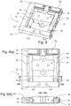
- FIG. 11 shows in view (a) a plan view onto a linear drive according to a third embodiment, and in view (b) a section along line IXb-IXb of FIG. 11 ( a ) .
- FIG. 12 shows a sectional view of the linear drive according to FIG. 11 ( a ) .
- FIG. 13 shows in view (a) schematically a potentiometer function of the linear drive according to the third embodiment for determining the position of the movement element, and in view (b) exemplified numerical values which illustrate the potentiometer function.
- the inventive linear drive 1 comprises an actuator unit, consisting of a pair of piezoelectric multi-layer actuators 3 a , 3 b each with a guide element 4 a , 4 b attached thereto in the form of a cylindrical rod 4 a , 4 b of structural ceramics arranged in parallel within a frame 2 .
- the frame 2 is composed of a cuboid basic part 2 a and a cuboid counterpart 2 b approximately of the same size.
- the basic part 2 a and the counterpart 2 b are connected via two plate-like side parts 2 c and 2 d to form an approximately rectangular surrounding frame 2 with an essentially cuboid outline, as can be seen, for example, in FIG. 2 .
- the basic part 2 a comprises, on an upper side visible in FIG. 3 ( a ) and preferably also at a side face facing away from the counterpart 2 b , two engagement sections 2 a 1 each formed as screw openings at a predetermined distance A 1 .
- the screw openings 2 a 1 act as standardised interface to mechanically couple the linear drive 1 with another identical linear drive 1 , such that the two linear drives 1 perform movements in two planes perpendicular with respect to each other (X; Y).
- the frame 2 and its components are preferably made of plastics and/or metal and/or ceramics.
- a pressure force is exerted, from two sides of the frame 2 by the side parts 2 c , 2 d formed as leaf spring via half bearings 2 e , 2 f , onto the guide elements 4 a , 4 b , and indirectly onto the movement element 5 arranged between the two guide elements 4 a , 4 b .
- the half bearings 2 e , 2 f are designed like a channel and each have a concave inner contour complementary to the cylindrical lateral area of the respective guide element 4 a , 4 b .
- the half bearings 2 e , 2 f support the guide elements 4 a , 4 b perpendicular to their direction of extension and movement and allow a sliding movement of the guide elements 4 a , 4 b in their direction of extension and movement.
- a bending of the guide elements 4 a , 4 b transverse to their direction of extension and movement, caused by the spread force of the inserted movement element 5 is thereby reduced or prevented, and a contact pressure between the movement element 5 and each of the guide elements 4 a , 4 b is increased.
- the counterpart 2 b preferably also has engagement sections ( 2 a 1 ) for coupling with an identical linear drive 1 corresponding to the basic part 2 a .
- the counterpart 2 b comprises centrically an essentially cuboid projection to which a leaf spring 2 g extending in a plane is attached.
- the two ends of the leaf spring 2 g facing away from each other in the direction of extension here extend at a distance in parallel to the side of the counterpart 2 b facing the basic part 2 a and serve as resilient bearing sections for the axial ends of the two guide elements 4 a , 4 b.
- the two drive units of the piezoelectric linear drive 1 have an identical design and each consist of a piezoelectric actuator 3 a , 3 b , and a guide element 4 a , 4 b coupled thereto.
- the piezoelectric actuator 3 a , 3 b is constructed in layers and has an approximately cubic design.
- the guide element 4 a , 4 b has a cylindrical shape with a diameter essentially corresponding to the edge length of the cubic actuator 3 a , 3 b .
- the two guide elements 4 a , 4 b are oriented exactly in parallel with respect to each other and are caused to move synchronously with respect to each other by the associated actuators 3 a , 3 b .
- the end faces of the guide elements 4 a , 4 b facing away from the actuators 3 a , 3 b are each resiliently mounted by the leaf spring 2 g at the counterpart 2 b of the frame 2 and are pressed towards the respective actuator 3 a , 3 b by the leaf spring 2 g.
- the end of the actuator 3 a facing away from the guide element 4 a is firmly connected to the basic part 2 a of the frame 2 .
- the end of the actuator 3 b facing away from the guide element 4 b can be movably mounted on the frame 2 along the basic part 2 a thereof.
- the movement element 5 has an approximately cuboid design. It comprises, at the two smallest side faces, wedge-shaped seatings 5 b in the form of channel-like V-grooves extending along the respective guide element 4 a , 4 b which are embodied, as is illustrated in FIG. 3 ( b ) , to receive the respective guide element 4 a , 4 b therein and be guided thereon with a stick-slip effect.
- annular contact sections 5 c in the form of friction clutches 5 c of structural ceramics each serving as friction elements and alternatingly slipping and sticking, by the stick-slip effect, at the associated contact surface of the respective guide element 4 a , 4 b .
- the cuboid shape of the movement element 5 is interrupted by two projections 5 d which extend at opposite sides of the movement element 5 along the intended moving direction of the movement element 5 . Between the upper side visible in FIG.
- engagement sections 5 e , 5 f for coupling the linear drive 1 with a further identical linear drive 1 .
- the diameters and distances of these engagement sections 5 e and 5 f , respectively, are identical, however offset with respect to each other by 90°.
- two identical linear drives 1 can be coupled to each other such that their travel ranges extend along two axes (X, Y; cf. FIG. 5 ) in two planes arranged perpendicular with respect to each other.
- an electric alternating voltage is applied to the actuator unit 3 , such that both guide elements 4 a , 4 b are caused to move synchronously and in parallel with respect to each other.
- the acceleration of the two guide elements 4 a , 4 b is sufficiently small in the stick phase, so that the stick engagement between the movement element 5 and each of the two guide elements 4 a , 4 b is maintained and the movement element 5 follows the movement of the guide elements 4 a , 4 b . Consequently, the movement element 5 undergoes an advance along its travel range.
- the moving direction of the guide elements 4 a , 4 b can be abruptly reversed, such that the movement element 5 moves slidingly along the two guide elements 4 a , 4 b in a slip phase.
- the inertial force of the movement element 5 is larger than the static friction force between the movement element 5 and the two guide elements 4 a , 4 b.
- the engagement structure between the movement element 5 and the two guide elements 4 a , 4 b here replaces a separate guide means since both the guide elements 4 a , 4 b and the movement element 5 only have one translational degree of freedom, while the other two translational degrees of freedom and all rotational degrees of freedom of both guide elements 4 a , 4 b and of the movement element 5 are blocked.
- the linear drive 1 operates according to the inertial drive principle. To obtain movements with a plurality of degrees of freedom (DOF), a plurality of linear drives 1 can be attached one upon the other, as is illustrated in FIGS. 6 and 7 .
- DOF degrees of freedom
- two linear drives 1 according to the invention are coupled to each other via respective engagement sections ( 5 e , 5 f ) of the movement elements 5 , such that the travel ranges of the two linear drives 1 extend along two axes X, Y in two planes arranged perpendicularly with respect to each other (leaving the thickness of the linear drives 1 out of consideration).
- a further linear drive 1 according to the invention is coupled with its basic part ( 2 a ) to the basic part ( 2 a ) of a linear drive 1 of the arrangement A, so that the altogether three linear drives 1 extend along three axes X, Y, Z in three planes arranged perpendicularly with respect to each other (leaving the thickness of the linear drives 1 out of consideration).
- multiaxially displaceable precision positioning means can be particularly easily and cheaply manufactured.
- the frame parts 2 a , 2 b and 2 c are embodied in one piece, different to the first embodiment, and form a C-shaped frame element which is connected with the strip- or plate-like side part 2 d to form a rectangle or square.
- the C-shaped frame element 2 a , 2 b and 2 c is essentially embodied to be rigid and unyielding, while the pretension on the guide elements 4 a , 4 b and the movement element 5 arranged therebetween is applied by the side part 2 d screwed to the C-shaped frame part 2 a , 2 b , and 2 c , the side part 2 d acting as a leaf spring.
- the leaf spring 2 g is embodied, for axially pretensioning the guide elements 4 a , 4 b in their directions of extension, as an H-shaped spring element whose two long legs extend in planes offset from each other by 90°, the short leg located centrically between the long legs being bent by 90°.
- a long leg of the H-shaped spring element is screwed to the upper side of the frame part 2 b via engagement sections or screw openings correspondingly provided for this purpose, with bolts, while the part of the leaf spring 2 g pretensioning the guide elements 4 a , 4 b extends in parallel to the inner side of the frame part 2 b facing the actuators 3 a , 3 b.
- FIGS. 11 and 12 A third embodiment of the linear drive 1 according to the invention is represented in FIGS. 11 and 12 .
- the frame 2 is composed of a cuboid basic part 2 a and a similar, preferably identical, counterpart 2 b .
- the basic part 2 a and the counterpart 2 b are connected to each other via two leaf springs 2 h , 2 i which are preferably fixed to the basic part 2 a and the counterpart 2 b by threaded joints.
- a seating element 8 a , 8 b which approximately has the same dimensions as the basic part 2 a or the counterpart 2 b , respectively, is fixed each to the basic part 2 a and to the counterpart 2 b , such that both seating elements 8 a , 8 b are opposed to each other within the frame 2 .
- the attachment to the basic part 2 a or to the counterpart is here preferably done via a threaded joint.
- the preferably identical seating elements 8 a , 8 b consist of an electrically non-conductive, preferably polymer-based material, and each have two through-holes 8 a 1 , 8 a 2 , 8 b 1 , 8 b 2 , in which the guide elements 4 a , 4 b are received and which serve as a sliding bearing.
- a through-hole 8 a 1 , 8 b 2 of each seating element 8 a , 8 b is designed such that the actuator 3 a , 3 b fixed to the respective guide element 4 a , 4 b can be additionally received therein, wherein an end face of the actuator 3 a , 3 b facing away from the respective guide element 4 a , 4 b is in contact with the basic part 2 a or the counterpart 2 b , respectively.
- an actuator 3 a is received in a through-hole 8 a 1 of the seating element 8 a which is connected to the basic part 2 a
- the other actuator 3 b is received in a through-hole 8 b 2 of the seating element 8 b which is connected to the counterpart 2 b . Consequently, the actuators 3 a , 3 b are located diagonally opposed with respect to the frame 2 .
- the movement element 5 is preferably provided with a spring element 6 in the form of a leaf spring via a threaded joint 7 .
- the spring element 6 extends perpendicularly to the moving direction and protrudes beyond the side faces of the movement element 5 arranged in parallel to the moving direction such that each guide element 4 a , 4 b is received in a channel-like seating, which is received by a side face of the movement element 5 and a section of the spring element 6 which protrudes beyond the movement element 5 .
- the side faces of the movement element 5 are embodied inclined to the main surfaces of the movement element 5 and provided with one or more contact sections 5 c .
- each guide element 4 a , 4 b is contacted directly via the contact sections 5 c , 6 c which serve as friction elements.
- the contact pressure on the guide elements 4 a , 4 b can be varied.
- a peripheral segment 4 a 1 , 4 b 1 of each guide element 4 a , 4 b is provided with a resistance material.
- the spring element 6 of the movement element 5 has, at its outer ends, slide sections 6 a which are in electrically conductive contact with the peripheral sections 4 a 1 , 4 b 1 of the guide elements 4 a , 4 b .
- the spring element 6 itself is also designed to be electrically conductive. In this manner, a potentiometer can be realised by which the position of the movement element 5 can be determined, as is illustrated in FIG. 13 by way of example.
- the peripheral sections 4 a 1 , 4 b 1 of the guide elements 4 a , 4 b have different resistance values R 1 , R 2 for this purpose. Due to the different resistance values R 1 , R 2 , the resistance R PQ changes from one point P of the peripheral section 4 a 1 of the guide element 4 a to a point Q of the peripheral section 4 b 1 of the other guide element 4 b with the position of the movement element 5 .
- FIG. 13 ( a ) schematically shows the preferred design of the potentiometer by which the position of the movement element 5 can be determined.
- the position of the movement element 5 is indicated as normalised position ⁇ which can assume values between 0 and 1 and changes with the position of the movement element 5 .
- the value 0 here preferably corresponds to a front end position of the movement element 5 where the movement element 5 is in contact with the seating element 8 a , and the value 1 to a rear end position where the movement element 5 is in contact with the seating element 8 b.
- FIG. 13 ( b ) shows, by way of example, the resistance values R PQ in response to the normalised position ⁇ of the movement element 5 with the assumption that R 1 is 10 k ⁇ and R 2 is 40 k ⁇ .
- inventive linear drives 1 according to the second and third inventive embodiments are couplable in the same way as the linear drives 1 according to the first inventive embodiment to form multiaxially displaceable arrangements.
- the linear drive 1 according to the second inventive embodiment has altogether fewer individual parts and a stabler basic construction, such that the freedom of motion of the individual components, in particular of the two guide elements 4 a , 4 b , is further restricted, and altogether, an even more precise positioning of the movement element 5 between the guide elements 4 a , 4 b can be achieved.
Abstract
The present disclosure relates to a linear drive, including: an actuator unit with at least one actuator; two guide elements and a movement element, wherein the movement element is displaceable along both guide elements by a movement generated by the actuator unit as a result of a stick-slip effect. In order to allow a more accurate displacement of the movement element in a compact design of the linear drive, the movement element can be brought into engagement with each of the two guide elements by static friction in order to be displaced along the two guide elements as a result of the stick-slip effect.
Description
The present invention relates to a linear drive, in particular for precision positioning means, comprising: an actuator unit with at least one actuator; two guide elements and a movement element, wherein the movement element can be displaced along both guide elements as a result of a stick-slip effect by means of a movement generated by the actuator unit.
U.S. Pat. No. 5,786,654 discloses (among others locations, in FIG. 1 and column 4, line 19, to column 5, line) a linear drive according to the preamble of patent claim 1, wherein a first one of the two guide elements (16) serve to generate the stick-slip effect (cf. column 4, lines 19 to 31), and a second one of the two guide elements (17) causes a torque-resistance (cf. column 4, lines 19 to 31) to block the rotational degree of freedom of the movement element about the first guide element (cf. column 4, lines 46 to 54). As an alternative to the second guide element (17), a linear ball guide (142, FIG. 23) can be provided, so that the movement element (12) does not rotate about the first guide element (16) when it is moved along the latter.
Independent of the type of actuation, whether it is electromagnetic or piezoelectric, precision guide elements such as linear bearings are widely employed in precision positioning tables. Despite the advantages of the provision of a high stiffness with concentric or parallel surfaces fitting over a large contact surface, these linear guide elements occupy the largest space, thereby limiting the miniaturisation of a device.
The object underlying the present invention is to provide a generic linear drive with a compact design and a more precise displaceability of the movement element.
To achieve this object, the present invention provides the linear drive according to claim 1, comprising: an actuator unit with at least one actuator; two guide elements and a movement element, wherein the movement element can be displaced along both guide elements as a result of a stick-slip effect by means of a movement generated by the actuator unit, wherein the movement element can be brought into engagement with each of the two guide elements by means of static friction in order to be displaced along the two guide elements as a result of the stick-slip effect. Thereby, both guide elements are used for generating the advance of the movement element, and the risk of a tilting of the movement element between the two guide elements, which does exist in a one-sided drive, is reduced. Thus, the clearance between the movement element and each one of the two guide elements required for displacing the movement element can be dimensioned comparably small. Moreover, the movement element can be fixed at both guide elements in a precise position by means of static friction.
Advantageous embodiments of the claimed invention are the subject matter of the depending claims.
The actuator is, for example, an electromagnetic or piezoelectric actuator. Preferably, the movement generated by the actuator unit is an electrically generated oscillation. The actuator unit can comprise one or more actuators, in particular piezo actuators, which serve as electromechanical converters and transmit an electric alternating voltage into an oscillating movement of the piezo actuator.
It can be advantageous for the actuator unit to be embodied to cause to move both guide elements simultaneously and/or synchronously and/or along parallel trajectories. Thereby, the two guide elements can particularly uniformly drive the movement element to generate the advance and can thus extremely accurately position it. It is also possible that the actuator unit can cause both guide elements to move at least in phases simultaneously and/or synchronously and/or along parallel trajectories, and at least in phases asynchronously and/or along non-parallel trajectories.
However, it can also prove to be of assistance if the movement element, in the stress-free state of the actuator unit (or in absence of control voltages or of the movement generated by the actuator unit), is engaged with each of the two guide elements by means of static friction. Thereby, in a standstill of the movement element, a relative movement with respect to each of the two guide elements can be effectively prevented. Mainly for the application of the linear drive in precision positioning means, this embodiment is of particular advantage.
It can moreover prove to be useful if each of the two guide elements and/or the movement element and/or at least one contact section of the movement element is formed of a non-magnetic or non-magnetisable material, preferably ceramics, preferably oxide ceramics, particularly preferred aluminium oxide. There are applications where a linear drive or at least its movement element has to be non-magnetic. If the guide elements are made of non-magnetic materials, such as structural ceramics or titanium, the linear drive, however, is also usable for special applications that require a non-magnetic or non-magnetisable linear drive. Moreover, in this embodiment, a high stick-slip effect between the guide elements and the movement element can be generated.
It can prove to be practical for the actuator unit to comprise two actuators which each drive one of the two guide elements. Preferably, each guide element is articulated or firmly connected to the actuator unit. The two actuators can have an identical design and be connected in parallel to drive the guide elements synchronously with respect to each other and generate a uniform advance of the movement element. Moreover, different movement patterns of the movement element can be represented compared to one single actuator. Preferably, the two actuators can be controlled independently. Thereby, a particular precise fine adjustment of the position of the movement element is also possible.
It can also be advantageous if the actuators are each arranged at one end of the guide elements and are arranged, with respect to a mid-plane perpendicular to the moving direction and bisecting the guide elements in the moving direction, on the same side or on opposite sides. An arrangement of the actuators on the same side of said plane facilitates the assembly of the linear drive, but can lead to different driving forces depending on the position of the movement element. This difference can cause a position-dependent step size of the movement element. In order to solve this problem, it is recommended to arrange the actuators on opposite sides of said plane.
It can be advantageous if each guide element and/or the movement element only have one translational degree of freedom, preferably all in parallel directions. Preferably, the other two translational degrees of freedom and all rotational degrees of freedom of both guide elements and/or the movement element are blocked. Thereby, positional errors during the displacement of the movement element along its travel range can be effectively eliminated. Moreover, the movement control of the movement element is relatively easy.
It can be advantageous if the movement element and the guide elements are configured such that in the stick phase between each guide element and the movement element, contact forces are generated in different directions and preferably symmetrical with respect to one plane. The plane preferably includes the axes of extension of the guide elements. Thereby, the movement element can be particularly easily centred in its intended central position and plane between the two guide elements.
However, it can also be useful if each guide element is embodied as a cylinder, and the trajectory of the guide element preferably extends along the cylinder axis. In this embodiment, the movement element can be positioned both during an advance along the travel range and in a standstill in a particularly stable position. In addition, a linear bearing is normally the most expensive part in a precision stage and can be omitted in this embodiment of the linear drive according to the invention.
It can also make sense for the movement element to receive each guide element in a separate channel-like seating, the channel-like seating being preferably embodied as a V-shaped groove which extends along the respective guide element and opens towards the latter. Thereby, the movement element can be fixed to each of the guide elements in a statically determined and stable manner, and high static frictional forces can be transmitted.
It can prove to be of assistance if the linear drive comprises a preferably closed frame, the frame preferably surrounding the actuator unit, the two guide elements and the movement element, the frame having, in a particularly preferred way, a cuboid outline. In an advantageous variant, the frame comprises four parts which approximately form a rectangle, in particular a basic part, a counterpart and two side parts which connect the basic part and the counterpart. The basic part and the counterpart are, for example, designed as a cuboid. The two side parts can be embodied in the form of a leaf spring or a plate. It can be of advantage for the actuator unit to comprise two actuators. and for the first actuator to be firmly coupled to the frame or the basic part, respectively, while the second actuator is firmly or movably coupled to the frame or the basic part, respectively.
However, it can also be advantageous for each guide element to be mounted resiliently with respect to the frame of the linear drive, preferably in its direction of extension and/or transverse to it, preferably via at least one leaf spring. Thereby, the contact pressure between the movement element and the guide element can be selectively adjusted. Preferably, each guide element is resiliently mounted at the counterpart of the frame against its moving direction, such that the deflection of the guide element in its moving direction leads to an increase of the spring tension.
In an advantageous embodiment, each guide element is slidingly mounted on the frame via a sliding bearing. The sliding bearing can support the guide element, for example sliding between its end-side bearing points, to prevent a bending of the guide element. The sliding bearing is preferably located on a side of the guide element facing away from the movement element.
However, it can also be practicable for each guide element to be resiliently pretensioned in the direction of the movement element and/or in the direction of the actuator unit. Thereby, the contact pressure between the guide element and the movement element, or between the guide element and the actuator element, respectively, is increased. In this way, the oscillation behaviour of the guide element or the static friction between the movement element and the guide element can be selectively adjusted. Preferably, the spring force is applied onto the guide element by a leaf spring and optionally a sliding bearing.
It can moreover make sense if a spring element is fixed to the movement element, and each guide element is received in a channel-like seating which is formed by a section of the movement element and a section of the spring element. By a purposeful selection of the material, the dimensions and/or the attachment points of the spring element, the contact pressure between the respective guide element and the movement element or the spring element, respectively, can be adjusted, whereby the friction and sliding conditions can be directly influenced.
It can also be advantageous for each guide element to comprise a peripheral section which is provided with a resistance material, and for the spring element to comprise slide sections which are each in electrically conductive contact with the peripheral section of the corresponding guide element. In this way, the linear drive can provide the function of a potentiometer by which the position of the movement element can be determined by detecting the electric resistance between a point of the peripheral section of the one guide element and a point of the peripheral section of the other guide element.
It can make sense for the frame and/or the movement element to comprise a mechanical interface which is couplable to the mechanical interface of an identical linear drive, such that the travel ranges of the linear drives coupled to each other extend in planes perpendicular with respect to each other. In this way, a multiaxially displaceable arrangement can be modularly set up from identical linear drives.
A further aspect of the present invention relates to an arrangement, comprising two or three linear drives according to one of the preceding embodiments, wherein the linear drives are coupled to each other such that the travel ranges of the linear drives coupled to each other extend in two or three planes perpendicular with respect to each other. The coupling of the linear drives is preferably accomplished by the mechanical interfaces according to the preceding embodiments.
An additional aspect of the invention relates to a method for determining the position of the movement element, wherein a resistance from a point of the peripheral section of a guide element to a point of the peripheral section of the other guide element is detected. With the determination of the position of the movement element, the movement element can be purposefully moved.
Further preferred developments result from combinations of the features disclosed in the claims, the drawings, and the description.
Linear Drive
The term linear drive designates a drive system leading to a translational movement. The movement of the linear drive can be effected along a travel range in a straight line or in another given course.
Stick-Slip Effect
The stick-slip effect designates the jerky sliding of solid bodies moved against each other and is known, among others, from U.S. Pat. No. 5,786,654. According to the invention, the displacement of the movement element along the guide elements by means of the stick-slip effect comprises a stick phase, in which the movement element is engaged with both guide elements by means of static friction, and a slip phase, in which the movement element moves relative to at least one guide element.
Actuator or Piezo Actuator
The term actuator designates a drive element which converts electric signals into mechanical movement. The actuator is, for example, a piezo actuator.
In the drawing:
The inventive linear drive 1 according to the preferred exemplified embodiment of the invention comprises an actuator unit, consisting of a pair of piezoelectric multi-layer actuators 3 a, 3 b each with a guide element 4 a, 4 b attached thereto in the form of a cylindrical rod 4 a, 4 b of structural ceramics arranged in parallel within a frame 2.
The frame 2 is composed of a cuboid basic part 2 a and a cuboid counterpart 2 b approximately of the same size. The basic part 2 a and the counterpart 2 b are connected via two plate- like side parts 2 c and 2 d to form an approximately rectangular surrounding frame 2 with an essentially cuboid outline, as can be seen, for example, in FIG. 2 .
The basic part 2 a comprises, on an upper side visible in FIG. 3(a) and preferably also at a side face facing away from the counterpart 2 b, two engagement sections 2 a 1 each formed as screw openings at a predetermined distance A1. The screw openings 2 a 1 act as standardised interface to mechanically couple the linear drive 1 with another identical linear drive 1, such that the two linear drives 1 perform movements in two planes perpendicular with respect to each other (X; Y). The frame 2 and its components are preferably made of plastics and/or metal and/or ceramics.
A pressure force is exerted, from two sides of the frame 2 by the side parts 2 c, 2 d formed as leaf spring via half bearings 2 e, 2 f, onto the guide elements 4 a, 4 b, and indirectly onto the movement element 5 arranged between the two guide elements 4 a, 4 b. The half bearings 2 e, 2 f are designed like a channel and each have a concave inner contour complementary to the cylindrical lateral area of the respective guide element 4 a, 4 b. The half bearings 2 e, 2 f support the guide elements 4 a, 4 b perpendicular to their direction of extension and movement and allow a sliding movement of the guide elements 4 a, 4 b in their direction of extension and movement. A bending of the guide elements 4 a, 4 b transverse to their direction of extension and movement, caused by the spread force of the inserted movement element 5, is thereby reduced or prevented, and a contact pressure between the movement element 5 and each of the guide elements 4 a, 4 b is increased.
The counterpart 2 b preferably also has engagement sections (2 a 1) for coupling with an identical linear drive 1 corresponding to the basic part 2 a. At the side facing the basic part 2 a, the counterpart 2 b comprises centrically an essentially cuboid projection to which a leaf spring 2 g extending in a plane is attached. The two ends of the leaf spring 2 g facing away from each other in the direction of extension here extend at a distance in parallel to the side of the counterpart 2 b facing the basic part 2 a and serve as resilient bearing sections for the axial ends of the two guide elements 4 a, 4 b.
The two drive units of the piezoelectric linear drive 1 have an identical design and each consist of a piezoelectric actuator 3 a, 3 b, and a guide element 4 a, 4 b coupled thereto. The piezoelectric actuator 3 a, 3 b is constructed in layers and has an approximately cubic design. The guide element 4 a, 4 b has a cylindrical shape with a diameter essentially corresponding to the edge length of the cubic actuator 3 a, 3 b. By applying an electric alternating voltage to the piezoelectric actuator 3 a, 3 b, the latter will be deformed such that the guide element 4 a, 4 b coupled thereto performs an oscillating movement along its axis of extension. The two guide elements 4 a, 4 b are oriented exactly in parallel with respect to each other and are caused to move synchronously with respect to each other by the associated actuators 3 a, 3 b. The end faces of the guide elements 4 a, 4 b facing away from the actuators 3 a, 3 b are each resiliently mounted by the leaf spring 2 g at the counterpart 2 b of the frame 2 and are pressed towards the respective actuator 3 a, 3 b by the leaf spring 2 g.
In the assembled state according to FIG. 1 , the end of the actuator 3 a facing away from the guide element 4 a is firmly connected to the basic part 2 a of the frame 2. In contrast, the end of the actuator 3 b facing away from the guide element 4 b can be movably mounted on the frame 2 along the basic part 2 a thereof. By a sliding or articulated mounting of an actuator 3 b at the basic part 2 a of the frame 2, a clamping by a tilting of the movement element 5 between the two guide elements 4 a, 4 b can be prevented.
In the present exemplified embodiment, the movement element 5 has an approximately cuboid design. It comprises, at the two smallest side faces, wedge-shaped seatings 5 b in the form of channel-like V-grooves extending along the respective guide element 4 a, 4 b which are embodied, as is illustrated in FIG. 3(b) , to receive the respective guide element 4 a, 4 b therein and be guided thereon with a stick-slip effect. At the two inner surfaces of the wedge-shaped seating 5 b facing each other, there are three annular contact sections 5 c in the form of friction clutches 5 c of structural ceramics each serving as friction elements and alternatingly slipping and sticking, by the stick-slip effect, at the associated contact surface of the respective guide element 4 a, 4 b. As is illustrated in FIG. 5(c) , the cuboid shape of the movement element 5 is interrupted by two projections 5 d which extend at opposite sides of the movement element 5 along the intended moving direction of the movement element 5. Between the upper side visible in FIG. 5(c) and the bottom side of the movement element 5 facing away therefrom, through bores or screw openings extend which are embodied as engagement sections 5 e, 5 f for coupling the linear drive 1 with a further identical linear drive 1. The diameters and distances of these engagement sections 5 e and 5 f, respectively, are identical, however offset with respect to each other by 90°. Via these engagement sections 5 e, 5 f, two identical linear drives 1 can be coupled to each other such that their travel ranges extend along two axes (X, Y; cf. FIG. 5 ) in two planes arranged perpendicular with respect to each other.
In order to displace the movement element 5 along the travel range between the basic part 2 a and the counterpart 2 b, an electric alternating voltage is applied to the actuator unit 3, such that both guide elements 4 a, 4 b are caused to move synchronously and in parallel with respect to each other. The acceleration of the two guide elements 4 a, 4 b is sufficiently small in the stick phase, so that the stick engagement between the movement element 5 and each of the two guide elements 4 a, 4 b is maintained and the movement element 5 follows the movement of the guide elements 4 a, 4 b. Consequently, the movement element 5 undergoes an advance along its travel range. By changing the control voltage applied to the actuators 3 a, 3 b, the moving direction of the guide elements 4 a, 4 b can be abruptly reversed, such that the movement element 5 moves slidingly along the two guide elements 4 a, 4 b in a slip phase. In the slip phase, the inertial force of the movement element 5 is larger than the static friction force between the movement element 5 and the two guide elements 4 a, 4 b.
The engagement structure between the movement element 5 and the two guide elements 4 a, 4 b here replaces a separate guide means since both the guide elements 4 a, 4 b and the movement element 5 only have one translational degree of freedom, while the other two translational degrees of freedom and all rotational degrees of freedom of both guide elements 4 a, 4 b and of the movement element 5 are blocked.
The linear drive 1 operates according to the inertial drive principle. To obtain movements with a plurality of degrees of freedom (DOF), a plurality of linear drives 1 can be attached one upon the other, as is illustrated in FIGS. 6 and 7 .
In the arrangement A according to FIG. 6 , two linear drives 1 according to the invention are coupled to each other via respective engagement sections (5 e, 5 f) of the movement elements 5, such that the travel ranges of the two linear drives 1 extend along two axes X, Y in two planes arranged perpendicularly with respect to each other (leaving the thickness of the linear drives 1 out of consideration).
In the arrangement B according to FIG. 7 , which is based on the arrangement A according to FIG. 6 , a further linear drive 1 according to the invention is coupled with its basic part (2 a) to the basic part (2 a) of a linear drive 1 of the arrangement A, so that the altogether three linear drives 1 extend along three axes X, Y, Z in three planes arranged perpendicularly with respect to each other (leaving the thickness of the linear drives 1 out of consideration).
With the linear drive 1 according to the invention, multiaxially displaceable precision positioning means can be particularly easily and cheaply manufactured.
In the second embodiment of the linear drive 1 according to the invention, which will be described below with reference to FIGS. 8 to 10 , the frame parts 2 a, 2 b and 2 c are embodied in one piece, different to the first embodiment, and form a C-shaped frame element which is connected with the strip- or plate-like side part 2 d to form a rectangle or square. Here, the C-shaped frame element 2 a, 2 b and 2 c is essentially embodied to be rigid and unyielding, while the pretension on the guide elements 4 a, 4 b and the movement element 5 arranged therebetween is applied by the side part 2 d screwed to the C-shaped frame part 2 a, 2 b, and 2 c, the side part 2 d acting as a leaf spring.
Equally different to the first embodiment, the leaf spring 2 g is embodied, for axially pretensioning the guide elements 4 a, 4 b in their directions of extension, as an H-shaped spring element whose two long legs extend in planes offset from each other by 90°, the short leg located centrically between the long legs being bent by 90°. Here, a long leg of the H-shaped spring element is screwed to the upper side of the frame part 2 b via engagement sections or screw openings correspondingly provided for this purpose, with bolts, while the part of the leaf spring 2 g pretensioning the guide elements 4 a, 4 b extends in parallel to the inner side of the frame part 2 b facing the actuators 3 a, 3 b.
A third embodiment of the linear drive 1 according to the invention is represented in FIGS. 11 and 12 . Similar to the first embodiment, the frame 2 is composed of a cuboid basic part 2 a and a similar, preferably identical, counterpart 2 b. The basic part 2 a and the counterpart 2 b are connected to each other via two leaf springs 2 h, 2 i which are preferably fixed to the basic part 2 a and the counterpart 2 b by threaded joints. A seating element 8 a, 8 b, which approximately has the same dimensions as the basic part 2 a or the counterpart 2 b, respectively, is fixed each to the basic part 2 a and to the counterpart 2 b, such that both seating elements 8 a, 8 b are opposed to each other within the frame 2. The attachment to the basic part 2 a or to the counterpart is here preferably done via a threaded joint. The preferably identical seating elements 8 a, 8 b consist of an electrically non-conductive, preferably polymer-based material, and each have two through-holes 8 a 1, 8 a 2, 8 b 1, 8 b 2, in which the guide elements 4 a, 4 b are received and which serve as a sliding bearing.
A through-hole 8 a 1, 8 b 2 of each seating element 8 a, 8 b is designed such that the actuator 3 a, 3 b fixed to the respective guide element 4 a, 4 b can be additionally received therein, wherein an end face of the actuator 3 a, 3 b facing away from the respective guide element 4 a, 4 b is in contact with the basic part 2 a or the counterpart 2 b, respectively. In this embodiment, an actuator 3 a is received in a through-hole 8 a 1 of the seating element 8 a which is connected to the basic part 2 a, and the other actuator 3 b is received in a through-hole 8 b 2 of the seating element 8 b which is connected to the counterpart 2 b. Consequently, the actuators 3 a, 3 b are located diagonally opposed with respect to the frame 2.
Due to the leaf springs 2 h, 2 i which connect the basic part 2 a and the counterpart 2 b with each other, the guide elements 4 a, 4 b are pressed against their corresponding actuators 3 a, 3 b.
The movement element 5 is preferably provided with a spring element 6 in the form of a leaf spring via a threaded joint 7. The spring element 6 extends perpendicularly to the moving direction and protrudes beyond the side faces of the movement element 5 arranged in parallel to the moving direction such that each guide element 4 a, 4 b is received in a channel-like seating, which is received by a side face of the movement element 5 and a section of the spring element 6 which protrudes beyond the movement element 5. In particular, here, the side faces of the movement element 5 are embodied inclined to the main surfaces of the movement element 5 and provided with one or more contact sections 5 c. Equally, the corresponding sections of the spring element are each provided with a contact section 6 c, such that each guide element 4 a, 4 b is contacted directly via the contact sections 5 c, 6 c which serve as friction elements. By selecting various materials, dimensions and/or attachment points of the spring element 6, the contact pressure on the guide elements 4 a, 4 b can be varied.
Furthermore, in this embodiment, a peripheral segment 4 a 1, 4 b 1 of each guide element 4 a, 4 b is provided with a resistance material. The spring element 6 of the movement element 5 has, at its outer ends, slide sections 6 a which are in electrically conductive contact with the peripheral sections 4 a 1, 4 b 1 of the guide elements 4 a, 4 b. The spring element 6 itself is also designed to be electrically conductive. In this manner, a potentiometer can be realised by which the position of the movement element 5 can be determined, as is illustrated in FIG. 13 by way of example. In particular, the peripheral sections 4 a 1, 4 b 1 of the guide elements 4 a, 4 b have different resistance values R1, R2 for this purpose. Due to the different resistance values R1, R2, the resistance RPQ changes from one point P of the peripheral section 4 a 1 of the guide element 4 a to a point Q of the peripheral section 4 b 1 of the other guide element 4 b with the position of the movement element 5.
In this configuration, the resistance RPQ is calculated according to the following formula: RPQ=αR1+(1−αR2).
The inventive linear drives 1 according to the second and third inventive embodiments are couplable in the same way as the linear drives 1 according to the first inventive embodiment to form multiaxially displaceable arrangements. In contrast to the first and third inventive embodiments, the linear drive 1 according to the second inventive embodiment, however, has altogether fewer individual parts and a stabler basic construction, such that the freedom of motion of the individual components, in particular of the two guide elements 4 a, 4 b, is further restricted, and altogether, an even more precise positioning of the movement element 5 between the guide elements 4 a, 4 b can be achieved.
In the second and third inventive embodiments, similar elements are provided with the same reference numerals as in the first inventive embodiment. In order to avoid repetitions, a separate description of equally acting elements is omitted.
- 1 piezoelectric linear drive
- 2 frame
- 2 a basic part
- 2 a 1 engagement section(s) or screw openings in the basic part
- 2 b counterpart
- 2 c, d side part(s) or leaf spring(s)
- 2 e, f coupling section(s) or half bearing(s)
- 2 g leaf spring
- 2 h, i leaf spring
- 3 actuator unit
- 3 a, b actuator(s)
- 4 a, b guide element(s)
- 4 a 1, 4
b 1 peripheral sections of theguide elements - 5 movement element
- 5 a body
- 5 b seating(s)
- 5 c contact section(s)
- 5 d projection
- 5 e engagement section(s) or screw openings in the movement element
- 5 f engagement section(s) or screw openings in the movement element
- 6 spring element
- 6 a slide section(s)
- 6 c contact section(s)
- 7 threaded joint
- 8 a, b seating element
- 8 a 1, 8 a 2 through-hole of the
seating 8 a - 8
b b 2 through-hole of theseating 8 b - A1 distance of the screw openings in the basic part
- A2 distance of the screw openings in the movement element
- B moving direction of the guide elements
Claims (20)
1. A linear drive, comprising:
an actuator unit with at least one actuator;
two guide elements;
a movement element, wherein the movement element is configured to be displaceable along both of the two guide elements as a result of a stick-slip effect by a movement generated by the actuator unit, wherein the movement element is configured to be brought into engagement with each of the two guide elements by static friction in order to be displaced along both of the two guide elements as a result of the stick-slip effect; and
a closed frame, which surrounds the actuator unit, the two guide elements and the movement element, wherein each of the two guide elements is resiliently mounted with respect to the closed frame transverse to the direction of extension of the respective one of the two guide elements, so that each of the two guide elements is resiliently pretensioned in a direction of the movement element and forces act in different directions.
2. The linear drive according to claim 1 , wherein the actuator unit is configured to cause both of the two guide elements to move simultaneously and/or synchronously and/or along parallel trajectories.
3. The linear drive according to claim 1 , wherein the movement element is, in a stress-free state of the actuator unit, engaged with each of the two guide elements by static friction.
4. The linear drive according to claim 1 , wherein the actuator unit comprises:
two actuators, each of the two actuators drives a respective one of the two guide elements.
5. The linear drive according to claim 4 , wherein each of the two actuators is arranged at a respective one end of the two guide elements and, with respect to a mid-plane that is perpendicular to a moving direction and bisects the two guide elements in the moving direction, are arranged on a same side or on opposite sides.
6. The linear drive according to claim 1 , wherein each of the two guide elements and/or the movement element only has/have one translational degree of freedom.
7. The linear drive according to claim 1 , wherein the movement element and the two guide elements are coupled such that in a stick phase between each of the two guide elements and the movement element, contact forces are generated in different directions and symmetrically to one plane.
8. The linear drive according to claim 1 , wherein each of the two guide elements is configured as a cylinder and a trajectory of the two guide elements extends along an axis of the cylinder.
9. The linear drive according to claim 1 , wherein the movement element receives each of the two guide elements in a separate channel-like seating, wherein the channel-like seating is embodied as a V-shaped groove which extends along a respective guide element and opens towards it.
10. The linear drive according to claim 1 , wherein the closed frame has a cuboid outline.
11. The linear drive according to claim 1 , wherein each of the two guide elements is resiliently mounted with respect to the closed frame of the linear drive, in and/or transverse to its direction of extension, via at least one leaf spring.
12. The linear drive according to claim 10 , wherein each of the two guide elements is mounted, via a sliding bearing at the closed frame in a sliding manner.
13. The linear drive according to claim 1 , wherein each of the two guide elements is resiliently pretensioned in a direction of the actuator unit.
14. The linear drive according to claim 1 , wherein a spring element is fixed to the movement element, and each of the two guide elements is received in a channel-like seating which is formed by a section of the movement element and a section of the spring element.
15. The linear drive according to claim 14 , wherein each of the two guide elements has a peripheral section which is provided with a resistance material, and the spring element has slide segments which are each in electrically conductive contact with a peripheral section of the corresponding guide element.
16. The linear drive according to claim 1 , wherein the closed frame and/or the movement element has/have a mechanical interface which is/are couplable to a mechanical interface of an identical linear drive, so that travel ranges (X, Y, Z) of the linear drives coupled to each other extend in planes perpendicular with respect to each other.
17. An arrangement, comprising:
two or three linear drives, wherein each of the two or three linear drives is configured according to claim 1 , wherein the two or three linear drives are coupled to each other such that travel ranges (X, Y, Z) of the two or three linear drives coupled to each other extend in two or three planes, respectively, perpendicular with respect to each other.
18. The linear drive according to claim 1 , wherein each of the two guide elements and/or the movement element only has/have one translational degree of freedom, wherein plural translational degrees of freedom of each of the two guide elements and/or the movement element are in parallel directions.
19. The linear drive according to claim 1 , wherein the movement element is, in a stress-free state of the actuator unit, engaged with each of the two guide elements by means of static friction.
20. A method of determining a position of a movement element with a linear drive, the linear drive including:
an actuator unit with at least one actuator;
two guide elements;
a movement element, wherein the movement is configured to be displaceable along both of the two guide elements as a result of a stick-slip effect by a movement generated by the actuator unit, wherein the movement element is configured to be brought into engagement with each of the two guide elements by static friction in order to be displaced along both of the two guide elements as a result of the stick-slip effect; and
a closed frame, which surrounds the actuator unit, the two guide elements and the movement element, wherein each of the two guide elements is resiliently mounted with respect to the closed frame transverse to the direction of extension of the respective one of the two guide elements, so that each of the two guide elements is resiliently pretensioned in a direction of the movement element and forces act in different directions;
wherein a spring element is fixed to the movement element, and each of the two guide elements is received in a channel-like seating which is formed by a section of the movement element and a section of the spring element;
wherein each of the two guide elements has a peripheral section which is provided with a resistance material, and the spring element has slide segments which are each in electrically conductive contact with a peripheral section of the corresponding guide element;
wherein the method comprises:
detecting a resistance from one point (P) of the peripheral section of one of the two guide elements to a point (Q) of the peripheral section of the other guide element.
Applications Claiming Priority (3)
| Application Number | Priority Date | Filing Date | Title |
|---|---|---|---|
| DE102018217709.0 | 2018-10-16 | ||
| DE102018217709.0A DE102018217709A1 (en) | 2018-10-16 | 2018-10-16 | linear actuator |
| PCT/EP2019/078057 WO2020079062A1 (en) | 2018-10-16 | 2019-10-16 | Linear drive |
Publications (2)
| Publication Number | Publication Date |
|---|---|
| US20210359624A1 US20210359624A1 (en) | 2021-11-18 |
| US11637508B2 true US11637508B2 (en) | 2023-04-25 |
Family
ID=68289980
Family Applications (1)
| Application Number | Title | Priority Date | Filing Date |
|---|---|---|---|
| US17/284,711 Active 2040-05-20 US11637508B2 (en) | 2018-10-16 | 2019-10-16 | Linear drive for precision positioning |
Country Status (5)
| Country | Link |
|---|---|
| US (1) | US11637508B2 (en) |
| EP (1) | EP3868015B1 (en) |
| JP (1) | JP7228689B2 (en) |
| DE (1) | DE102018217709A1 (en) |
| WO (1) | WO2020079062A1 (en) |
Families Citing this family (1)
| Publication number | Priority date | Publication date | Assignee | Title |
|---|---|---|---|---|
| DE102020118300A1 (en) | 2020-07-10 | 2022-01-13 | SmarAct Holding GmbH | Inertial drive and related procedure |
Citations (16)
| Publication number | Priority date | Publication date | Assignee | Title |
|---|---|---|---|---|
| EP0464764A1 (en) | 1990-07-03 | 1992-01-08 | Canon Kabushiki Kaisha | Driving device |
| JPH07298654A (en) | 1994-04-26 | 1995-11-10 | Minolta Co Ltd | Driver |
| WO1998019347A2 (en) | 1996-10-26 | 1998-05-07 | Artur Zrenner | Piezoelectric or electrostrictive inertia drive for displacing or positioning in particular heavy objects |
| US5786654A (en) | 1995-06-08 | 1998-07-28 | Minolta Co., Ltd. | Movable stage utilizing electromechanical transducer |
| US6188161B1 (en) | 1997-06-02 | 2001-02-13 | Minolta Co., Ltd. | Driving apparatus using transducer |
| US6940210B2 (en) | 2000-11-23 | 2005-09-06 | Attocube Systems Ag | Inertial rotation device |
| DE102008003879A1 (en) | 2007-01-25 | 2008-07-31 | Siemens Aktiengesellschaft | Linear drive for driving movable object, comprises piezoactuator which is controlled by controller and mechanical frictional engagement is formed to transfer drive force between transducer and object to be moved |
| KR20090021990A (en) | 2007-08-29 | 2009-03-04 | (주)피에조테크놀리지 | Stage apparatus using a piezoelectric linear motor |
| US20100115671A1 (en) | 2008-11-04 | 2010-05-06 | Dr. Sergiy Pryadkin | inertial positioner and an optical instrument for precise positioning |
| US20110018393A1 (en) | 2009-07-27 | 2011-01-27 | Taketo Nakamura | Vibratory driving device |
| US20120212844A1 (en) | 2011-02-23 | 2012-08-23 | Intermec Ip Corp. | Linear actuator assemblies and methods of making the same |
| DE102012104749A1 (en) | 2011-06-03 | 2012-12-06 | Academia Sinica | Multi-axis actuator device |
| EP2590315A1 (en) | 2011-11-02 | 2013-05-08 | Physik Instrumente (PI) GmbH & Co. KG | Drive device |
| US9692323B2 (en) | 2011-03-30 | 2017-06-27 | SmarAct Holding GmbH | Method for actuating a multi-actuator drive device |
| US20170310247A1 (en) | 2014-10-09 | 2017-10-26 | Attocube Systems Ag | Stick-slip drive, especially piezo-actuated inertial drive |
| US20190032759A1 (en) * | 2017-07-27 | 2019-01-31 | Uchicago Argonne, Llc | Method and precision nanopositioning apparatus with compact vertical and horizontal linear nanopositioning flexure stages for implementing enhanced nanopositioning performance |
Family Cites Families (1)
| Publication number | Priority date | Publication date | Assignee | Title |
|---|---|---|---|---|
| US8059346B2 (en) * | 2007-03-19 | 2011-11-15 | New Scale Technologies | Linear drive systems and methods thereof |
-
2018
- 2018-10-16 DE DE102018217709.0A patent/DE102018217709A1/en active Pending
-
2019
- 2019-10-16 JP JP2021521045A patent/JP7228689B2/en active Active
- 2019-10-16 EP EP19789952.9A patent/EP3868015B1/en active Active
- 2019-10-16 US US17/284,711 patent/US11637508B2/en active Active
- 2019-10-16 WO PCT/EP2019/078057 patent/WO2020079062A1/en active Search and Examination
Patent Citations (16)
| Publication number | Priority date | Publication date | Assignee | Title |
|---|---|---|---|---|
| EP0464764A1 (en) | 1990-07-03 | 1992-01-08 | Canon Kabushiki Kaisha | Driving device |
| JPH07298654A (en) | 1994-04-26 | 1995-11-10 | Minolta Co Ltd | Driver |
| US5786654A (en) | 1995-06-08 | 1998-07-28 | Minolta Co., Ltd. | Movable stage utilizing electromechanical transducer |
| WO1998019347A2 (en) | 1996-10-26 | 1998-05-07 | Artur Zrenner | Piezoelectric or electrostrictive inertia drive for displacing or positioning in particular heavy objects |
| US6188161B1 (en) | 1997-06-02 | 2001-02-13 | Minolta Co., Ltd. | Driving apparatus using transducer |
| US6940210B2 (en) | 2000-11-23 | 2005-09-06 | Attocube Systems Ag | Inertial rotation device |
| DE102008003879A1 (en) | 2007-01-25 | 2008-07-31 | Siemens Aktiengesellschaft | Linear drive for driving movable object, comprises piezoactuator which is controlled by controller and mechanical frictional engagement is formed to transfer drive force between transducer and object to be moved |
| KR20090021990A (en) | 2007-08-29 | 2009-03-04 | (주)피에조테크놀리지 | Stage apparatus using a piezoelectric linear motor |
| US20100115671A1 (en) | 2008-11-04 | 2010-05-06 | Dr. Sergiy Pryadkin | inertial positioner and an optical instrument for precise positioning |
| US20110018393A1 (en) | 2009-07-27 | 2011-01-27 | Taketo Nakamura | Vibratory driving device |
| US20120212844A1 (en) | 2011-02-23 | 2012-08-23 | Intermec Ip Corp. | Linear actuator assemblies and methods of making the same |
| US9692323B2 (en) | 2011-03-30 | 2017-06-27 | SmarAct Holding GmbH | Method for actuating a multi-actuator drive device |
| DE102012104749A1 (en) | 2011-06-03 | 2012-12-06 | Academia Sinica | Multi-axis actuator device |
| EP2590315A1 (en) | 2011-11-02 | 2013-05-08 | Physik Instrumente (PI) GmbH & Co. KG | Drive device |
| US20170310247A1 (en) | 2014-10-09 | 2017-10-26 | Attocube Systems Ag | Stick-slip drive, especially piezo-actuated inertial drive |
| US20190032759A1 (en) * | 2017-07-27 | 2019-01-31 | Uchicago Argonne, Llc | Method and precision nanopositioning apparatus with compact vertical and horizontal linear nanopositioning flexure stages for implementing enhanced nanopositioning performance |
Non-Patent Citations (4)
| Title |
|---|
| International Search Report (PCT/ISA/210) and Written Opinion (PCT/ISA/237) dated Feb. 3, 2020, by the European Patent Office as the International Searching Authority for International Application No. PCT/EP2019/078057. |
| Office Action (Notice of Grounds of Rejection) dated May 31, 2022, by the Japanese Patent Office in corresponding Japanese Patent Application No. 2021-521045, and an English Translation of the Office Action. (13 pages). |
| Search Report dated Apr. 30, 2020 by the German Patent Office for Application No. 10 2018 217 709.0. |
| Search Report dated May 20, 2019 by the German Patent Office for Application No. 10 2018 217 709.0. |
Also Published As
| Publication number | Publication date |
|---|---|
| EP3868015A1 (en) | 2021-08-25 |
| JP2022505133A (en) | 2022-01-14 |
| EP3868015B1 (en) | 2022-11-23 |
| JP7228689B2 (en) | 2023-02-24 |
| DE102018217709A1 (en) | 2020-04-16 |
| WO2020079062A1 (en) | 2020-04-23 |
| US20210359624A1 (en) | 2021-11-18 |
Similar Documents
| Publication | Publication Date | Title |
|---|---|---|
| EP2122702B1 (en) | Optical adjustment mounts with piezoelectric inertia driver | |
| US6715731B1 (en) | Piezoelectric valve | |
| EP3329150B1 (en) | Multi-degree-of-freedom adjustment mechanism | |
| US6188161B1 (en) | Driving apparatus using transducer | |
| US7301257B2 (en) | Motion actuator | |
| US20170030514A1 (en) | Linkage rod including limited-displacement flexible mechanism | |
| US11637508B2 (en) | Linear drive for precision positioning | |
| US10161560B2 (en) | Integrated picomotor mount | |
| KR102371621B1 (en) | joint | |
| EP3329149B1 (en) | Linkage rod including limited-displacement flexible mechanism | |
| KR20020090396A (en) | Ultra-precision moving apparatus | |
| JP6358392B2 (en) | Integrated linear movement mechanism | |
| US20220029559A1 (en) | Electromechanical Linear Drive | |
| EP4220932A1 (en) | Piezoelectric motor having nanometer-scale resolution | |
| KR20240050349A (en) | Apparatus and method for positioning optical instruments | |
| JP6369741B2 (en) | Positioning mechanism | |
| JPS62125408A (en) | Fine adjustment mechanism | |
| CN117337542A (en) | Linear or rotary table capable of moving in two dimensions | |
| JPH0676804U (en) | Magnetic circuit | |
| JPH09215355A (en) | Moving stage employing electro-mechanical transducer |
Legal Events
| Date | Code | Title | Description |
|---|---|---|---|
| AS | Assignment |
Owner name: PHYSIK INSTRUMENTE (PI) GMBH & CO. KG, GERMANY Free format text: ASSIGNMENT OF ASSIGNORS INTEREST;ASSIGNOR:KOC, BURHANETTIN;REEL/FRAME:055894/0179 Effective date: 20210412 |
|
| FEPP | Fee payment procedure |
Free format text: ENTITY STATUS SET TO UNDISCOUNTED (ORIGINAL EVENT CODE: BIG.); ENTITY STATUS OF PATENT OWNER: LARGE ENTITY |
|
| STPP | Information on status: patent application and granting procedure in general |
Free format text: DOCKETED NEW CASE - READY FOR EXAMINATION |
|
| STCF | Information on status: patent grant |
Free format text: PATENTED CASE |