EP0442613A2 - Dispositif de détection de mise au point - Google Patents
Dispositif de détection de mise au point Download PDFInfo
- Publication number
- EP0442613A2 EP0442613A2 EP91300393A EP91300393A EP0442613A2 EP 0442613 A2 EP0442613 A2 EP 0442613A2 EP 91300393 A EP91300393 A EP 91300393A EP 91300393 A EP91300393 A EP 91300393A EP 0442613 A2 EP0442613 A2 EP 0442613A2
- Authority
- EP
- European Patent Office
- Prior art keywords
- optical system
- focus
- information
- mode
- focus detecting
- Prior art date
- Legal status (The legal status is an assumption and is not a legal conclusion. Google has not performed a legal analysis and makes no representation as to the accuracy of the status listed.)
- Granted
Links
Images


Classifications
-
- G—PHYSICS
- G02—OPTICS
- G02B—OPTICAL ELEMENTS, SYSTEMS OR APPARATUS
- G02B7/00—Mountings, adjusting means, or light-tight connections, for optical elements
- G02B7/28—Systems for automatic generation of focusing signals
- G02B7/34—Systems for automatic generation of focusing signals using different areas in a pupil plane
- G02B7/346—Systems for automatic generation of focusing signals using different areas in a pupil plane using horizontal and vertical areas in the pupil plane, i.e. wide area autofocusing
Definitions
- the present invention relates to a focus detecting device for use in a camera or the like.
- Said device is based on a principle of forming a pair of images of an object on a photoelectric converting device from a pair of light beams passing through a phototaking optical system by means of a focus detecting optical system of so-called split pupil type, obtaining image signals of said object by photoelectric conversion of said images by said photoelectric converting device, and effecting a predetermined calculation on said image signals thereby determining the defocus amount of the phototaking optical system.
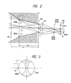
- Fig. 1 illustrates a focus detecting optical system of so-called split pupil system, disclosed in the U.S. Patent Application Ser. No. 457,408 of the present applicant.
- Said optical system is composed of a field mask 300 positioned at the primary image plane of the phototaking optical system and provided with an aperture 300A for defining the area of focus detection in the object field, a field lend 301 positioned behind said field mask; re-imaging lenses 303A, 303B, 303C, 303D arranged in two pairs for re-imaging the images of an object on a secondary image plane; and a diaphragm mask 302 positioned in front of said re-imaging lenses and provided with four apertures 302A, 302B, 302C, 302D for limiting the light beams entering said re-imaging lenses.
- re-focused object images are respectively projected onto photosensor units (for example CCD image sensors) 304A, 304B, 304C, 304D of the photoelectric converting device 304 positioned at the secondary image plane, whereby object image signals corresponding to the light intensity distributions of the object images are generated from said photosensor units.
- photosensor units for example CCD image sensors
- the forms of four apertures 302A, 302B, 302C, 302D are projected by the field lens 301 onto a pupil plane 305 (hereinafter also called a focus detecting pupil) positioned at a predetermined distance d0 from the primary image plane, wherein the projected forms respectively constitute pupil areas 305A, 305B, 305C, 305D (hereinafter also called focus detecting pupil diaphragms). Consequently the object images re-focused on the secondary image plane are solely formed by the light beams passing through said pupil areas 305A, 305B, 305C and 305D.
- a pupil plane 305 hereinafter also called a focus detecting pupil
- Fig. 2 is a cross-sectional view, along a plane containing the X- and Z-axes, of the focus detecting optical system shown in Fig. 1.
- the rays passing through the pupil area 305A or 305B and concentrated between end points A and C in the X-direction of the aperture 300A of the field mask 300 have always to pass through an area between hatched portions (said area being defined inside lines A-F and C-H from the primary image plane to the pupil plane 305 at a distance d0 there-from, and inside extensions of lines C-F and A-H beyond said pupil plane 305, wherein F and H are external end points in the X-direction of the pupil areas 305A, 305B).
- the phototaking optical system has a relatively small F-number so that the external end points of the exit pupil thereof are positioned in the hatched portions, the light beams used for focus detection do not cause vignetting and do not have undesirable effect on the focus detection.
- the F-number becomes larger so that the external end points of the exit pupil are positioned in the internal area, said light beams show vignetting which undesirably affects the focus detection.
- the influence of vignetting on the focus detection depends also on the pupil position as well as the size of the exit pupil 101.
- the pupil areas 305A, 305B on the pupil plane 305 are shaped as shown in Fig. 3. Consequently, the rays which are concentrated on all the points of the aperture 300A of the field mask 300 and then pass through the apertures 302A, 302B should have passed the pupil areas 305A, 305B on the pupil plane 305.
- the exit pupil 101 of the phototaking optical system is positioned at the pupil plane 305, the rays passing through the different points of the aperture 300A and falling onto the photoelectric converting device 304 are subjected to uniform vignetting even in the presence of vignetting. Therefore the vignetting does not cause any undesirable influence but merely results in a uniform loss in the light intensity received by the photosensor units of the photoelectric converting device 304.
- the rays passing through the different points of the aperture 300A of the field mask 300 and falling onto the photoelectric converting device 304 pass through spatially different areas.
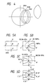
- light beams which are concentrated on points A, B and C of the aperture 300A shown in Fig. 1 and then pass through the aperture 302B of the diaphragm mask 302 pass through respectively different areas 306A, 306B and 306C shown in Fig. 4 on a plane at a position d1 different from that of the pupil plane 305.
- Figs. 5A, 5B, 5C and 5D illustrate the states of such vignetting.
- points A′, B′, C′, D′, E′, A ⁇ , B ⁇ , C ⁇ , D ⁇ and E ⁇ correspond to the points A, B, C, D and E of the aperture 300A shown in Fig. 5A after re-focusing by the lenses 303A, 303B.
- Figs. 5B and 5C show the vignetting in the image of the aperture 300A re-focused by the lenses 303A, 303B.
- the vignetting does not appear in an area inside the solid line (an area including the point A for the image formed by the re-focusing lens 303A; and an area including the point C for the image formed by the lens 303B), so that the amount of light is 100%.
- the vignetting occurs in such a way that the amount of light is reduced to 90 - 100 % in an area between the solid line and the broken line, and is reduced below 90 % outside the broken line.
- the vignetting-free areas do not overlap each other as shown in Fig. 5D, and exact focus detection becomes impossible because two images to be compared for the focus detection do not coincide each other.
- the above-mentioned drawback is resolved by the use of two focus detecting systems with different F-numbers and by selecting a focus detecting system free from the vignetting, according to the F-number of the phototaking optical system.
- the F-number for focus detection is determined by the size of a circumscribed circle including the pupil areas 305A, 305B, 305C and 305D on the pupil plane 305 shown in Fig. 1 and the position d0 of said pupil plane.
- the above-mentioned drawback is resolved by calculating the amount of vignetting from the F-number of the exit pupil of the phototaking optical system and the positional information of said exit pupil, and effecting the calculation for focus detection so as to reduce the influence of the vignetting according to thus calculated amount of vignetting.
- the object of the present invention is to prevent the deterioration in the accuracy of focus detection resulting from the losses in the peripheral light amount in the phototaking optical system and in the focus detecting optical system.
- the focus detecting device of the present invention is provided with a phototaking optical system 1 for forming the image of an object on a reference plane; a focus detecting optical system 2 for separating, from the light beams passing through said phototaking optical system 1, at least a pair of light beams passing through spatially different areas on a first predetermined plane axially spaced by a first distance from said reference plane; a photoelectric converting device 3 consisting of plural photosensor elements and adapted to generate object image signals corresponding to the light intensity distribution of the image of the object, an information generating device 4 for the phototaking optical system, for generating information on the F-number of the exit pupil at the fully-open diaphragm aperture of the phototaking optical system 1, a second distance from said reference plane to the exit pupil, and the loss in the light amount in the peripheral area of the phototaking optical system 1; an information generating device 5 for the focus detecting optical system, for generating information on the size of said areas on said first predetermined plane, said first distance, and the loss in
- the above-mentioned information generating device 4 for the phototaking optical system may be so designed to further generate information on the shape and position of the aperture portion of lens barrel (for example lens holding ring and hood), that may further limit the phototaking light beams in addition to the diaphragm, and such information may be utilized in the detecting device 6 for determining the light amount distribution on the photosensor elements of the photoelectric converting device 3 when the phototaking optical system 1 is combined with the focus detecting optical system 2.
- the loss in the light amount in case the phototaking optical system 1 and the focus detecting optical system 2 are mutually combined is calculated as the light amount distribution information, based on the information of the phototaking system and of the focus detecting system.
- the object image signals generated by the photoelectric converting device 3 are processed according to said distribution information, and the focus detecting calculation is conducted by the image signals after said processing. Consequently, even in case the focus detecting optical system 2 is combined with various phototaking optical systems 1, the overall loss in the light amount, including the loss by the vignetting in the focus detecting light beams and the loss in peripheral light beams in the optical systems, can be exactly calculated.
- the processing of the object image signals according to the light amount distribution information may be, for example, elimination of an image signal showing significant light amount loss, correction of the image signals according to the light amount loss, or elimination of low frequency components from the image signals in case of significant light amount loss.
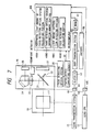
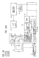
- Fig. 7 is a block diagram showing the entire structure of a single-lens reflex camera equipped with a focus detecting device of the present invention.
- an interchangeable lens 10 is detachably mountable on a camera body 20.
- a phototaking light beam coming from an object is transmitted by a phototaking lens 11, then partly reflected by a main mirror 21 provided in the camera body 20 toward a finder, and is further transmitted by a focusing screen 23, a pentagonal prism 24 and an eyepiece lens 25 whereby an image formed on the focusing screen is observed by the photographer.
- the remaining part of the light beam is transmitted by the main mirror 21, then reflected by a sub mirror 22 and guided as a focus detecting light beam to a focus detecting optical system 30.
- Said focus detecting optical system 30 can be constructed, for example, as shown in Fig. 1, wherein an object image focused by the phototaking lens 11 is re-focused on photosensor elements of a photoelectric converting device 32.
- the light-receiving face of the photosensor elements constitutes a focus detecting plane (conjugate with the film) of the focus detecting optical system 30.
- the photosensor elements of the photoelectric converting circuit 32 effect photoelectric conversion on the object image re-focused by the focus detecting optical system 30 thereby generating object image signals.
- Said image signals are supplied to a microcomputer 400 of the camera body, for use in various calculations to be explained later.
- the microcomputer 400 is equipped with a portion 400A for calculating the peripheral light amount of the focus detecting optical system; a memory portion 400B for information on the focus detecting optical system; a light amount distribution detecting portion 400C; and a focus detecting calculating portion 400D, of which details will be explained later.
- a portion 400A for calculating the peripheral light amount of the focus detecting optical system a memory portion 400B for information on the focus detecting optical system
- a light amount distribution detecting portion 400C for information on the focus detecting optical system
- a focus detecting calculating portion 400D of which details will be explained later.
- known internal mechanisms of camera such as a shutter device 27 and an unrepresented film advancing mechanism.
- An auto focusing (AF) motor 51 is driven according to the defocus amount calculated by the microcomputer 400, and axially moves a focusing lens of the phototaking lens 11, through a body transmission system 52, a clutch 53, couplings 54, 18 and a lens transmission system 13.
- An encoder 55 detects the number of rotations of the AF motor 51 and enters it into the microcomputer 400.
- a lens CPU 12 generates information on the peripheral light amount of the phototaking lens 11, the F-number f0 of the exit pupil at the fully-open diagrams aperture, and the position of the exit pupil (d1 in Fig. 2) with respect to the film plane, and enters said information into the microcomputer 400 through couplings 59E, 19E.
- the lens CPU 12 detects the focusing and zooming positions and varies said information according to the detected focusing and zooming positions.
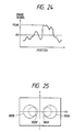
- the information on the peripheral light amount of the phototaking lens 11 is given as shown in Fig. 8, by a function F(d) of the distance d from the optical axis on the image plane.
- the lens CPU 12 If the phototaking lens 11 has the exit pupil of a special shape, the lens CPU 12 generates information on the shape and position of the diaphragm instead of the F-number. For example, in case of a reflex lens, the lens CPU generates information on the circumscribed F-number and inscribed F-number of the diaphragm and the pupil positions thereof.
- the memory portion 400B for the information of focus detecting optical system stores in advance information on the peripheral light amount of the focus detecting optical system 30, pupil position (d0 in Fig. 2) for focus detection, and shape and position of pupil diaphragm for focus detection.
- the information on the shape and position of the focus detecting pupil diaphragm are external radius r0, internal radius r1 and center d2 of the internal radius r1.
- the peripheral light amount calculating portion 400A for the focus detecting optical system 30 converts the peripheral light amount on a plane of the photosensor elements of the photoelectric converting circuit 32 into the position of the photographed image plane, in a form similar to the information on the peripheral light amount of the phototaking lens 11.
- the information on peripheral light amount is not point symmetric with respect to the center, as in the equation (1).
- the peripheral light amount can be represented by the following equation (2), utilizing two-dimensional axes X, Y with centers at points corresponding to the optical axis (for example B′, B ⁇ in Fig.
- peripheral light amount information may be represented by the light amount in each of small cells (x, y) into which the photoelectric converting plane is divided.
- peripheral light amount information of the focus detecting optical system may be determined by the output of the photosensor elements in a state in which an object of uniform luminocity is focused on the focus detecting plane (conjuagate with the film) of the focus detecting optical system, or by the design data of the optical system.
- the light amount distribution detecting portion 400C detects the distribution of light amount on the photosensor elements, for an object of uniform luminocity, based on the information from the lens CPU 12 and the peripheral light amount calculating portion 400A. Said distribution is determined for each image formed by the focus detecting optical system 30, For example, in case of the optical system shown in Fig. 1, the light amount distribution is determined for each of the four lenses 303A, 303B, 303C and 303D.
- the light amount distribution for example of the re-focusing lens 303B is determined in the following manner, in case the phototaking lens 11 has the exit pupil at d1, a fully-open F-number f0 and a peripheral light amount information F(x, y); and the focus detecting optical system 30 has a structure shown in Fig. 1 with the focus detecting pupil at d0, the focus detecting pupil diaphragm of circular shape with a radius r2 and the center at (xb, 0) on the focus detecting pupil plane as shown in Fig. 9 and with the peripheral light amount information Gb(x, y).
- a light beam passing through a point (x0, y0) of the aperture 300A and the re-focusing lens 303B forms, on the exit pupil plane of the phototaking lens 11, a circle P with a radius r3 and with the center at (x1, y1) as shown in Fig. 10.
- the exit pupil of the phototaking lens 11 on the pupil plane forms a circle Q with a radius r4 and with the center at (0, 0).
- Kb(x, y) F(x, y) ⁇ Gb(x, y) ⁇ Jb(x, y)
- the vignetting information Ja(x, y), Jc(x, y) and Jd(x, y) for the lenses 303A, 303C and 303D can be determined in a similar manner, and the light amount distribution information Ka(x, y), Kc(x, y) and Kd(x, y) can be obtained based on other peripheral light amount information Ga(x, y), Gc(x, y) and Gd(x, y) of the focus detecting optical system 30.
- Figs. 11A and 11B illustrate the behavior of the light amount distribution information Ka(x, y).
- the focus detection calculating portion 400D detects the defocus amount between the current image plane of the phototaking lens 11 and the film plane, by applying a known focus detecting calculation on the object image signals released by the photoelectric converting circuit 32.
- a correlation amount C(L) is determined from the output data ap, bp by a correlation calculation shown by the following equation (5): wherein L is an integer, indicating the amount of relative shift of paired output data of the photosensor elements, represented by the pitch of arrangement of photosensor cells. Also in the summation of the equation (5), the range of the parameter i is suitably determined according to the shift amount L and the data number n.
- the parameters C(km) and SLOP obtained from the equations (6) allow to judge the reliability of the defocus amount DEF, and said parameters are used for determining whether the focus detection is possible or not.
- the focus detection calculating portion 400D also determines the range data, to be employed in the correlation calculation according to the equations (5), based on the light amount distribution information. For example, when the light amount distribution information Ka(x, y) is determined as shown in Fig. 12 and the data a1 - an of the photosensor element 304A are set on the image field, data au - aw with light amounts at least equal to a predetermined value t % are employed in the correlation calculation.
- the range of data to be employed in the correlation calculation can be similarly determined for other data bi, ci and di. In this manner it is rendered possible to reduce the unbalance between the data resulting from loss in the light amount, in the correlation calculation, and to improve the accuracy of focus detection.
- the data a′i, b′i, c′i and d′i converted according to the equation (8) are used, instead of the original data ai, bi, ci and di, in the correlation calculation according to the equations (5).
- Such conversion allows to eliminate the low frequency components of the image signals, resulting from the loss in light amount, thereby improving the accuracy of the focus detection.
- the calculating portion 400D may vary, according to the light amount distribution information, the threshold reference value in judging the reliability of the defocus amount DEF by the parameters C(km) and SLOP obtained from the equations (6). For example, if said distribution information indicates a significant loss in light amount, said reference value may be lowered to avoid the reduction in the reliability resulting from the loss in light amount. In this manner a constant determination whether the focus detection is possible or not can be obtained for a same object, regardless of the presence or absence of loss in light amount.
- the object image signals may be corrected, according to the light amount distribution information, to image signals corresponding to a uniform state without loss in light amount.
- the photoelectric converting device is composed of a pair of two-dimensional sensors with output image signals Sa(x, y) and Sb(x, y), with light amount distribution information Ka(x, y) and Kb(x, y)
- Such correction corrects the loss in light amount included in the image signals, thereby enabling the calculating portion 400D to effect exact correlation calculation and improving the accuracy of focus detection.
- Fig. 13A shows a main flow chart of said program.
- a step S100 calculates the light amount distribution information ka - kd.
- a step S200 effects a predetermined process on the image signals, based on thus calculated distribution information ka - kd, and a step S300 determines the defocus amount by a focus detecting calculation based on thus processed image signals.
- the lens is driven based on said defocus amount, according to an unrepresented control sequence.
- the light amount distribution information ka - kd are determined according to a flow chart shown in Fig. 13B.
- a step S101 determines the peripheral light amount F(d) of the phototaking lens 11 according to the equation (1), by fetching said equation (1), stored in the lens CPU 12, into the microcomputer 400 of the camera body.
- a next step S102 determines the peripheral light amounts Ga(x, y) - Gd(x, y) of the focus detecting optical system from the equations (2).
- a step S103 determines the vignetting information Ja(x, y) - Jd(x, y) from the equations (3)
- a step S104 determines the light amount distribution information ka(x, y) - kd(x, y) from the equation (4).
- Fig. 13C shows a pre-editing procedure for the image signals.
- a step S201 discriminates whether the light amount distribution information ka(x, y) - kd(x, y) are smaller than a reference value. If larger, said step S201 is negated and a step S202 stores the image signals as Sa(x, y) - Sd(x, y) in a memory. If smaller, the sequence jumps to a step S203 for discriminating whether the comparison has been completed for all the pixels, and, if completed, the sequence of Fig. 13C is terminated. Thus the image signals are stored in the memory only when the distribution information ka(x, y) - kd(x, y) are larger than the reference value.
- Fig. 13D is a flow chart of focus detecting calculation.
- a step S301 determines the correlation C(L) from the pre-edited image signals, according to the known calculation of the equations (5). Then a step S302 determines the shift amount kj of high correlation according to the equations (6), and a step S303 determines the defocus amount from the equations (7).
- the pre-editing procedure shown in Fig. 13C stores only the image signals of which light amount distribution information are larger than the reference in the memory, but it is also possible to store all the image signals in the memory by applying the correction of the equations (9) based on the light amount distribution information ka - kd.
- a step S221 discriminates the presence of light amount distribution information ka - kd smaller than the reference value, and, if affirmative, a step S222 effects filtering for removing the low frequency components according to the equations (8), and thus filtered image signals are used for focus detecting calculation.
- the focus detecting optical system may be constructed as shown in Fig. 1, or as shown in Fig. 14.
- the structure shown in Fig. 14 is composed of a field mask 300 having a two-dimensional aperture 300A; a field lens 301; a diaphragm mask 302 having a pair of apertures 302A, 302B; a pair of re-focusing lenses 303A, 303B; and a photoelectric converting device 304 provided with photosensor areas 304A, 304B in which photosensor elements are two-dimensionally arranged.
- Such structure realizes two-dimensional arrangement of focus detecting areas (AF areas) on the image plane, and enables arbitrary change of the focus detecting areas based on the selection of AF areas or on the result of viewing point detection to be explained later.
- the focus detecting optical system 30 may be constructed as shown in Fig. 15.
- the diaphragm mask 302 is composed of a physical device capable of electrically varying the light transmittance, such as an electrochromic (EC) or liquid crystal (LC) device, and the apertures thereof can be shifted between those 302A, 302B shown in Fig. 14 and those 302A′, 302B′ with smaller radius of circumscribed circles as shown in Fig. 15, by electrical control from the outside.
- EC electrochromic
- LC liquid crystal
- said apertures can be switched to the apertures 302A′, 302B′ with smaller radius of circumscribed circles thereby reducing the focus detecting diaphragms on the focus detecting pupil plane and thus avoiding the vignetting.
- the circumscribed circles are reduced by a size reduction of the apertures 302A′, 302B′, but, for a lens with an annular exit pupil such as a reflex lens, the inscribed circles of the apertures 302A′, 302B; can be increased in order to avoid vignetting of the focus detecting diaphragm inside the annular exit pupil.
- the focus detecting optical system 30 may be constructed as shown in Fig. 16.
- the diaphragm mask 302 and the re-focusing lenses are different in structure from those in Fig. 15, and the apertures 302A, 302B of the diaphragm mask 302 shown in Fig. 15 can be shifted to those 302C, 302D with a different direction of arrangement by external electrical control.
- Re-focusing lenses 303C, 303D are provided behind said apertures 302C, 302D.
- Such structure allows to select the apertures arranged in a direction of easier focus detection, depending on the pattern of the object, thereby improving the accuracy of focus detection.
- a common photoelectric converting area may be used for the apertures 302A, 302B and re-focusing lenses 303A, 303B, or the apertures 302C, 302D and re-focusing lenses 303C, 303D.
- the problem of image overlapping can be avoided because the images by the lenses 303A, 303B and those by the lenses 303C, 303D are not formed at the same time.
- the direction of arrangement of the apertures 302C, 302D is perpendicular to that of the apertures 302A, 302B, but there may be naturally selected other directions of arrangement.
- a physical device is employed for switching the form of the apertures, but plural apertures may be switched in mechanical manner.
- the AF detection system controlling CPU 33 has the functions of selecting the aforementioned AF diaphragm according to an instruction by the AF calculating CPU 40 to be explained later or according to its own discretion, controlling the functions such as charge accumulation and charge transfer of the photoelectric converting device 32 with already known control signals and transfer clock signals, and storing the transferred image signals into the memory 34 after A/D conversion.
- Fig. 17 is a flow chart showing an example of control sequence of the AF detection system controlling CPU 33.
- a step S000 effects charge accumulation in the photoelectric converting device 32 for a predetermined accumulating time.
- a step S005 changes a header indicating the memory storage area of the A/D-converted output data of the photoelectric converting device 32.
- a step S010 effects transfer of the output of said device 32, A/D conversion, data correction and storage in the memory, for each data.
- Said data correction includes the calculation according to the equations (9) for correction for the peripheral light amount.
- the controlling CPU 33 incorporates the information of the focus detecting optical system, and receives the information on the phototaking optical system from the lens CPU 12.
- a step S015 changes the header, indicating the latest data storage area, to the current data storage area, and a step S020 determines the next accumulating time in such a manner that the peak value of the obtained image data becomes equal to a predetermined value. Then the sequence returns to the step S000 to repeat the above-explained sequence.
- Fig. 18 conceptually shows the changes in the data storage areas in the memory 34 in the above-explained procedure. If a latest data storage area and a data storage area currently under data storage are arranged as indicated "this time", the current data storage area will become the latest data storage area in the next time. Since the headers of the latest data storage area and the current data storage area are stored in the memory 34, the AF calculating CPU 40 can always utilize the latest data from the latest data storage area for the focus detecting calculation by reading the header of said area from the memory 34. Also since the control operation for the photoelectric converting device 32 and the focus detecting calculation are separated, these two operations can be conducted in parallel manner, so that the efficiency in time or the response of focus detection can be improved.
- Fig. 19A is a timing chart of the above-explained procedure, in which the signal transfer is started immediately after the completion of the charge accumulation of the photoelectric converting device 32, and the next charge accumulation is started immediately after the completion of the signal transfer.
- the charge accumulation and the signal transfer are mutually separated in time, but these operations may mutually overlap as shown in Figs. 19B or 19C.
- the charge accumulating time is longer than the signal transfer time, the signal transfer and the next charge accumulation are started immediately after the completion of the charge accumulation, as shown in Fig. 19B.
- the charge accumulating time is shorter, as shown in Fig.
- the signal transfer is started immediately after the completion of the charge transfer, and the next charge accumulation is started at a suitable timing in such a manner that said next charge accumulation will be completed immediately after the completion of the signal transfer.
- Such mutually overlapping charge accumulation and signal transfer in time improves the efficiency in time, or the response of the focus detecting operation, and allows to absorb the loss in response, resulting from the increase in number of data in the use of a two-dimensional photoelectric converting device.
- a rectangular two-demensional photosensor area as shown in Fig. 20A may be divided into n blocks YB1 - YBn oblong parallel to the X-axis, and charge accumulation and signal transfer may be conducted in time-separated manner for each block.
- a structure shown in Fig. 20A ensures the simultaneous character of data in the X-direction, and is therefore better matched with the apertures 302A, 302B arranged in the X-direction, on the diaphragm mask shown in Fig. 21.
- the photosensor area in case of using the apertures 302C, 302D arranged in the Y-direction, it is preferable to divide the photosensor area into n blocks XB1 - XBn oblong in a direction perpendicular to the X-axis, as shown in Fig. 20B, and to effect the charge accumulation and the signal transfer in time-separated manner for each block, thereby ensuring simultaneous character of the data in the Y-direction.
- the charge accumulating operation may be divided into plural portions as shown in Fig. 19D, thereby effecting the accumulation plural times in a flickering cycle of the light source, thereby alleviating the influence of said flickering.
- the charge transfer time may be saved by effecting the normal transfer operation only in an image area to be used in the focus detecting calculation and a high-speed transfer operation in other areas.
- the data usable for focus detection are defined by broken-lined areas in Fig. 22A or 22B respectively corresponding to the use of apertures 302A, 302B arranged in the X-direction on the diaphragm mask shown in Fig.
- the normal transfer operation is conducted only for the output data corresponding to the interior of the broken lines and high-speed transfer operation is conducted, without the A/D conversion and the storage in the memory, for other areas. Also information indicating the correlation between the data stored in the memory by normal transfer operation and the areas thereof on the photosensor areas is stored in the memory and is utilized in the focus detecting calculation by the AF calculating CPU 40.
- the data used for focus detection are desirably obtained from the central portion of the image field.
- the charge accumulating time of the photoelectric converting device 32 is so determined that the image data have a predetermined peak value, but such determination of the next accumulating time by the image data may result in an oscillation phenomenon in case the object is illuminated by a light source with cyclically varying intensity, such as a fluorescent lamp.
- a monitor device in the vicinity of the photoelectric converting device for monitoring the average intensity of object image on real time basis and terminating the charge accumulation of the photosensor area when the monitor signal reaches a predetermined value, the peak value may exceed the range of A/D conversion for certain objects composed for example of white lines on a black background.
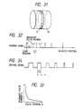
- Figs. 23 and 24 show a method for controlling the charge accumulating time for resolving such drawback.
- the monitor signal is reset to a value VR simultaneously with the start of charge accumulation.
- the monitor signal increase according to the average brightness of the object image, and reaches a predetermined value Vs after a time Tm from resetting.
- the AF detection system controlling CPU 33 determines the current accumulating time Ti according to the following equation, based on the peak value PEAK of the previous image data shown in Fig.
- the AF detection system controlling CPU 33 may switch the apertures 302A, 302B of the diaphragm mask shown in Fig. 25 to those 302C, 302D with less tendency of vignetting.
- the apertures 302A, 302B of the diaphragm mask shown in Fig. 21 may be switched to those 302C, 302D. Information on such switching is supplied to the AF calculating CPU 40, which effects processing accordingly.
- the AF calculating CPU 40 has a function of effecting known focus detecting calculation on the image data stored in the memory 34, thereby determining the defocus amount of the phototaking optical system.
- said CPU effects, as disclosed in the U.S. Patent Application Ser. No. 457,408 of the present applicant, the focus detecting calculation on each of plural blocks formed in the focus detecting area, and selects an optimum defocus amount from thus calculated plural defocus amounts, according to various principles.
- the focus detecting calculation conducted by the AF calculating CPU 40 is principally composed, as shown in Fig.
- step S030 for data correction and conversion a step S035 for selecting the focus detecting area, a step S040 for block division, a step S045 for defocus amount calculation for each block, and a step S050 for final defocus amount selection, and said CPU 40 repeats these steps.
- the data correction/conversion step also includes the calculation according to the equations (9) for peripheral light amount correction.
- the AF calculating CPU 40 executes the correction of the equations (9) by determining the light amount distribution information, based on the information of the focus detecting optical system incorporated in said CPU or received from the AF detection system controlling CPU 33 and the information of the phototaking optical system received from the lens CPU 12.
- data conversion is conducted by filtering for eliminating the low frequency components as shown by the equations (8).
- Such data conversion may be applied solely to an object containing a large amount of high frequency components, as identified by the contrast of the object.
- an image signal as shown in Fig. 28A or 28B is divided into plural blocks, and contrast CON is detected in each of said blocks according to the equation (11).
- Such selective application of the data conversion by filtering, according to the image contrast enables focus detecting calculation on an object containing a large amount of low frequency components without filtration of such low frequency components, thereby improving the accuracy of focus detection.
- the focus detection area selecting step selects, for example, either a narrow spot area at the center of image field or a wide area for focus detection, as shown in Fig. 29A, by a suitable method. Also there may be arbitrarily selected a focus detecting area or areas at arbitrary position(s), as shown in Fig. 29B, either manually by the AF area selecting device 66 or by the viewing point detecting device 68.
- Figs. 30A and 30B illustrate an example of the viewing point detecting device 68.
- a planar infrared-emitting element 683 projects infrared light through a half mirror 681, a lens 680 and an infrared-reflecting dichroic mirror 682 provided in the eyepiece lens 25, to an eye 685 of the finder viewing person.
- the shapes and positions of the optical components are so selected that the light-emitting face of said element 683 overlaps in shape and position with the image field in the view-finder.
- the infrared light projected to the eye 685 of the observer is reflected by a retina 686, reflected by the dichroic mirror 682 in the eyepiece lens 25, transmitted by the lens 680 and the half mirror 681 and is received by a planar photosensor 684.
- a retina 686 reflected by the dichroic mirror 682 in the eyepiece lens 25, transmitted by the lens 680 and the half mirror 681 and is received by a planar photosensor 684.
- an area of the photosensor 684 receives a larger amount of light, corresponding to an area of the finder screen watched by the observer.
- the difference in the light amount distribution received by the planar photosensor 684 between the light-emitting state of the planar infrared-emitting device 683 and the deactivated state thereof, as shown in Fig. 30B, and the viewing point is detected from an area of maximum light reception in said distribution.
- the result of said viewing point detection may be used for selecting the focus detecting area as explained before, or for selecting an area for spot light metering.
- the planar photosensor 684 may be composed of a two-dimensional CCD sensor, or a position sensor for detecting the center of gravity of light reception.
- the planar infrared-emitting device 683 may be replaced by a two-dimensional beam scanning. Also since said detection of viewing point may be erroneously affected by the winking of the observer, the total received light is monitored and data with lowered total received light are excluded from said detection. Also the stability of detection is improved by reducing the response in time, for example by statistical treatment, in order not to follow the winking or momentary fluctuation of the viewing point.
- the step S040 for block division in Fig. 27 divides the focus detecting area, selected in the preceding step, into plural blocks according to the object pattern. For example, an image signal as shown in Fig. 28A or 28B is divided into plural blocks, and a contrast detection according to the equation (11) is conducted in each block. If a predetermined contrast is not obtained in any of the blocks, the object is identified as a low-frequency object, and the focus detecting area is divided into a fewer number of blocks as shown in Fig. 28C (broken lines indicating the boundaries of blocks). If said predetermined contrast is obtained in at least one block, the area is divided into a larger number of blocks as shown in Fig. 28D.
- the step S045 for defocus amount calculation for each block applies the known focus detecting calculation to each of the blocks divided in the preceding step. Thus the defocus amount can be determined in each of the blocks.
- the step S055 for selecting final defocus amount determines a defocus amount from the above-mentioned plural defocus amounts, according to a predetermined algorithm. For example, if the selecting algorithm is based on priority in the center, there is selected the defocus amount of a block which is closest to the center of image field and in which the focus detection is possible. Also there is selected a defocus amount indicating a shortest object distance in case of priority to the shortest distance; a defocus amount indicating a longest object distance in case of priority to the longest distance; an average of the calculated defocus amounts or an average weighted by reliability in case of priority to the average; or a defocus amount with the smallest absolute value in case of priority to the current status.
- the AF area can be selected as shown in Tab. 1, by an AF area selecting device 66 provided on the camera body.
- a view point detection mode selects an area based on the result obtained by said viewing point detecting device 68; a center spot mode selects a spot area at the center of image field as shown in Fig. 29A; a selected spot mode selects spot areas arbitrarily selected in the image field as shown in Fig. 29B; a wide mode selects a wide area shown in Fig. 29A; and horizontal and vertical modes select areas respectively corresponding to horizontal photosensor elements 304A, 304B or vertical photosensor elements 304C, 304D in the focus detecting optical system shown in Fig. 1. Also a center spot-wide mode selects the center spot area before focusing and then the wide AF area after in-focus state is once obtained. Such manual selection of the AF area enables the photographer to select an optimum area for the object.
- the algorithm may be switched as indicated in the right-hand column of Tab. 1 in connection with the selection of the AF area.
- the algorithm is shifted to an average priority mode to approximately focus to all the plural objects.
- the algorithm is shifted to a center priority mode to focus to the object at the center or image field.
- the algorithm is set at a minimum distance priority ⁇ present condition priority mode, thereby focusing to a closest object until an in-focus state is obtained and then increasing the stability by the present priority mode avoiding the unnecessary lens drive by an eventual obstacle at the even shorter distance.
- the algorithm is set at the minimum distance priority mode to constantly focus to an object at the shortest distance.
- the algorithm can be selected as shown in Tab. 2, by an AF object selecting device 67 provided on the camera body.
- a center priority-present condition priority mode indicates to adopt the center priority mode before focusing and the present condition priority mode after the in-focus state is reached
- a minimum distance priority-present condition priority mode indicates to adopt the minimum distance priority mode before focusing and the present condition priority mode after the in-focus state is reached.
- the AF area may be switched as indicated in the center column of Tab. 2, in connection with the algorithm selection.
- the center priority mode or the minimum distance priority mode of algorithm matches better with a smaller AF area, the center spot mode is selected for the AF area.
- the maximum distance priority mode or the minimum distance priority-present condition priority mode of the algorithm selection there is preferred a larger AF area so that the wide mode is selected for the AF area.
- the center priority ⁇ present condition priority mode of algorithm selection the AF area is selected at the center spot-wide mode in order to maintain a small AF area before focusing and to improve the stability with a wide AF area after the in-focus state is reached.
- the AF area and the algorithm are selected as respectively indicated in the center and right ⁇ hand columns in Tab. 3.
- the center spot AF area is selected and the center priority mode is selected for the algorithm.
- the selected spot light metering mode selecting plural positions in the image field, the selected spot mode is selected also for the AF area, and the minimum distance priority mode is selected for the algorithm.
- the AF area selection is set at the center spot-wide mode and the algorithm is set at the center priority-present condition priority mode.
- the wide mode is selected for the AF area and the minimum distance priority-present condition priority mode is selected for the algorithm. In this manner satisfactory correlation is maintained between the AF area and the light metering area, and there can be improved the stability of auto focusing and the selectively for the object.
- the AF area and the algorithm may be selected as respectively shown in the center and right-hand columns.
- the aperture priority AE mode which is mostly used for photographing an object stopped at the center of image field
- the center spot ⁇ wide mode is selected for the AF area
- the center priority ⁇ present condition priority mode is selected for the algorithm, in order to improve the selectivity for the object.
- the shutter speed priority AE mode mostly used for a moving object
- the wide mode is selected for the AF area and the minimum distance priority mode is selected for the algorithm, in order to improve the object following ability.
- the wide AF area mode is selected and the minimum distance priority-present condition priority mode is selected for the algorithm, in order to improve the object following ability and the stability.
- the AF area and the algorithm optimum for the object can be selected by merely selecting the AE mode according to the object.
- the AF area and the algorithm may be respectively selected as shown in the center and right-hand columns.
- the AF area and the algorithm are respectively set at the center spot mode and the center priority mode, in order to improve the selectivity for the object.
- the AF area and the algorithm are respectively set at the wide mode and the minimum distance priority-present condition priority mode, in order to improve the object following ability and the auto focusing stability.
- the AF area is set at the center spot-wide mode while the algorithm is set at the minimum distance priority-present condition priority mode, thereby mixing the following ability and the selectivity for the object.
- the self-timer winding mode in which the position of the main object cannot be predicted in the image field, there are selected the wide AF area mode and the minimum distance priority algorithm, in order to securely follow the object. In this manner, mere selection of the film winding mode according to the photographing situation enables to select the optimum AF area and algorithm for said situation.
- the AF area and the algorithm may be selected respectively as shown in the center and right-hand columns.
- Selection of a photographing mode automatically selects a light metering mode, an AE mode, a film winding mode and a focusing mode optimum for each photographing condition.
- the sports photographing mode mostly used for a moving object, there are selected the wide AF area and the minimum distance priority ⁇ present condition priority mode for the algorithm, for improving the object following ability.
- the center spot mode for the AF area and the minimum distance priority mode for the algorithm for improving the selectivity for the object.
- the snap photographing mode in which the object is not necessarily positioned at the center, there are selected the wide AF area mode and the minimum distance priority ⁇ present condition priority mode for the algorithm, thereby improving the object following ability and the auto focusing stability.
- the center spot mode for the AF area and the center priority mode for the algorithm in which enough time is often available for changing the image framing with focus locking after focusing with the main object at the center, there are selected the center spot mode for the AF area and the center priority mode for the algorithm, thereby improving the selectivity for the object.
- the center spot AF area mode and the center priority mode for the algorithm In this manner the selection of the photographing mode according to the object allows to select the optimum AF area and algorithm for said object.
- the AF area and the algorithm may be respectively selected as shown in the center and right-hand columns.
- the single focus mode mostly used for a stopped object, there are selected the center spot mode for the AF area and the center priority mode for the algorithm, thereby improving the selectivity for the object.
- the continuous focus mode mostly used for a moving object
- the wide mode for the AF area and the minimum distance priority-present condition priority mode for the algorithm there are selected the wide mode for the AF area and the minimum distance priority-present condition priority mode for the algorithm, thereby improving the object following ability and the auto focusing stability.
- the focus tracking mode which is often used for an object moving closer to the camera
- there are selected the center spot ⁇ wide mode for the AF area and the minimum distance priority mode for the algorithm thereby improving the object selectivity and the object following ability.
- the power focus mode in which time for image frame change is not available in most cases, there are selected the wide AF area and the minimum distance priority ⁇ present condition priority mode for the algorithm, thereby improving the object following ability.
- the switching of the AF area and algorithm may also be conducted, as shown in Fig. 8, based on the comparison of the time T elapsed from the half-stroke depression of a shutter release button 61 and a redetermined time T1. If the elapsed time T is shorter than said predetermined time T1, there are selected the center spot mode for the AF area and the minimum distance priority mode for the algorithm, thus giving emphasis to the object selectivity. If the former is equal to or longer than the latter, there are selected the wide AF area and the present condition priority mode for the algorithm, thus giving emphasis to the object following ability and the auto focusing stability.
- the AF area and algorithm may be selected as shown in the center and right-hand columns in Tab. 9, according to said information.
- the object distance information can be obtained for example from the defocus amount determined from the focus detection and the absolute position of the phototaking lens.
- the center spot mode for the AF area and the center priority mode for the algorithm.
- the object distance is long, the object appears smaller and more difficult to catch in the image field, there are selected the wide AF area and the minimum distance priority-present condition priority mode for the algorithm.
- the object distance is medium, there are selected intermediate selections, namely the center spot-wide mode for the AF area and the minimum distance priority-present condition priority mode for the algorithm. In this manner optimum AF area and algorithm can be selected according to the object distance.
- the AF area and algorithm may be selected as shown in the center and right-hand columns in Tab. 10, according to said information.
- the magnification information can be obtained, for example, from the defocus amount determined from focus detection, the absolute position of the phototaking lens, and the focal length thereof.
- the magnification is large, the object appears large and the focus varies considerably depending on the position in the image field. Therefore, in order to increase the selectivity for the object, there are selected the center spot mode for the AF area and the center priority mode for the algorithm.
- the magnification is small, the object appears smaller and more difficult to catch in the image field, there are selected the wide AF area and the minimum distance priority-present condition priority mode for the algorithm.
- magnification is medium
- intermediate selections namely the center spot-wide mode for the AF area and the minimum distance priority-present condition priority mode for the algorithm. In this manner optimum AF area and algorithm can be selected according to the photographing magnification.
- the AF area and algorithm may be selected as shown in the center and right-hand columns in Tab. 11, according to said information.
- the focal length information can be obtained, for example, from the lens information sent from the lens CPU 12.
- the center spot mode for the AF area and the center priority mode for the algorithm In a macro mode the object appears large and the focus varies considerably depending on the position in the image field. Therefore, in order to increase the selectivity for the object, there are selected the center spot mode for the AF area and the center priority mode for the algorithm.
- the object appears smaller and more difficult to catch in the image field, there are selected the wide AF area and the minimum distance priority-present condition priority mode for the algorithm.
- there are made intermediate selections namely the center spot-wide for the AF area and the minimum distance priority-present condition priority mode for the algorithm. In this manner optimum AF area and algorith can be selected according to the focal length information.
- the AF area and algorithm are selected for a smaller area to increase the object selectivity if the object appears larger in the image field, but for a larger area to facilitate the capture of object if the object appears smaller in the image field. It is possible also, however, to select the AF area and algorithm for a wider area if the object appears larger in the image field because the object itself is large already, thereby facilitating the capture of object and improving the auto focusing stability, and to select the AF area and algorithm for a smaller area if the object appears smaller in the image field thereby improving the selectivity for the object.
- the AF area and algorithm may be selected as shown in the center and right-hand columns in Tab. 12, according to said information.
- the aperture value information can be obtained from the main CPU 60 controlling the aperture control device 83.
- the aperture value is small, requiring a higher accuracy in focusing, there are selected the center spot AF area and the center priority mode for the algorithm, thereby improving the object selectivity.
- the aperture value is large, where the depth of focus is large and does not require a high accuracy in focusing, there are selected the wide AF area and the average priority mode for the algorithm. In this manner there are selected optimum AF area and algorithm according to the aperture value information.
- the AF area and algorithm may be selected as shown in the center and right-hand columns in Tab. 13, according to said information.
- the shutter speed information can be obtained from the main CPU 60 controlling the shutter speed control device 82.
- the wide AF area and the minimum distance priority-present condition priority mode for the algorithm in order to improve the object capturing ability.
- For a low shutter speed, often used for a stopped object there are selected the center spot AF area and the center priority-present condition priority mode for the algorithm, thereby improving the object selectivity. In this manner optimum AF area and algorithm can be selected according to the shutter speed information.
- the AF area and the algorithm may be selected as shown in the center and right-hand columns in Tab. 14, according to said information.
- the object luminance information can be obtained, for example, from the result of luminance detection by the main CPU 60 based on the output of the light metering sensor 86.
- the center spot AF area and the center priority mode for the algorithm thus giving emphasis on the object selectivity.
- the wide AF area and the minimum distance priority mode for the algorithm giving emphasis to the object capturing ability. In this manner optimum AF area and algorithm can be selected according to the object luminance information.
- the AF area and the algorithm may be selected as shown in the center and right-hand columns in Tab. 15, according to said information.
- the electronic flash information can be obtained by communication with the main CPU 60 controlling the built-in electronic flash unit or with a CPU incorporated in the electronic flash unit.
- the object is of a high luminance and is clearly identifiable in most cases, so that selected are the center spot AF area and the center priority mode for the algorithm, thereby giving emphasis to the object selectivity.
- the object is of a low luminance and is not clearly identifiable in most cases, so that there are selected the wide AF area and the minimum distance priority mode for the algorithm, thus giving emphasis to the object capturing ability. In this manner optimum AF area and algorithm can be selected according to the electronic flash information.
- the AF area and the algorithm may be selected as shown in the center and right-hand columns in Tab. 16, according to said information.
- the aberration information can be obtained, for example, from the lens information supplied by the lens CPU 12.
- the difference in aberration between the axial and peripheral positions is large (for example a large image plane curvature)
- there are selected the center spot AF area and the center priority mode for the algorithm because the focus detection on or near the axial position provides better accuracy.
- the wide AF area and the minimum distance priority-present condition priority mode for the algorithm since enough accuracy can be obtained even by the focus detection in the peripheral area. In this manner optimum AF area and algorithm can be selected according to the aberration information.
- the AF area and the algorithm may be selected as shown in the center and right-hand columns in Tab. 17, according to said information.
- the body position information can be obtained, for example, from a position detecting device 69, such as a mercury switch, provided in the camera body.
- a position detecting device 69 such as a mercury switch
- the vertical photosensor elements shown in Fig. 1 are selected as the AF area, and the minimum distance priority mode is selected for the algorithm.
- the horizontal photosensor elements shown in Fig. 1 are selected as the AF area, and the minimum distance priority-present condition priority mode is selected for the algorithm. In this manner optimum AF area and algorithm can be selected according to the body position information.
- the AF area and the algorithm may be selected as shown in the center and right-hand columns in Tab. 18, according to said information.
- the object pattern information can be obtained in the AF calculating CPU 40 itself, for example by applying the equations (11) to the image data for focus detection. If the object pattern has a high contrast, the object can be clearly identifiable in most cases, so that there are selected the center spot AF area and the center priority mode for the algorithm, giving emphasis to the object selectivity. In case of a low contrast, where the object may not be clearly identifiable, there are selected the wide AF area and the minimum distance priority-present condition priority mode for the algorithm, in order to give emphasis to the object capturing ability. In this manner optimum AF area and algorithm can be selected according to the object pattern information.
- the AF area and the algorithm may be selected as shown in the center and right-hand columns in Tab. 19, according to said information.
- the defocus information can be obtained, for example, from the AF calculating CPU 40 itself executing the focus detecting calculation. If the defocus amount is small, the object is clearly identifiable in most cases, and there is required a limited mutual displacement of the image data in the correlation calculation for focus detection. Consequently there are selected the center spot AF area an d the center priority mode for the algorithm, thus giving emphasis to the object selectivity.
- the parameters C(km) and SLOP determined in the equations (6) are capable of determining the reliability of the defocus amount DEF, and can therefore be used for discriminating whether the focus detection is possible or not, as shown in the relations (13): C(km) > Cs or SLOP ⁇ Ss... detection impossible C(km) ⁇ Cs and SLOP ⁇ Ss... detection possible (13)
- the discrimination of the status of focus detection optimum for said conditions can be realized by varying the values Cs, Ss in (13) in relation to said conditions. More specifically said values are selected tightly (smaller Cs and larger Ss) in a state where exact focus detection is possible or necessary (small AF area; algorithm in center priority mode or minimum distance priority mode; spot light metering mode; aperture value priority AE mode; single film winding mode; portrait photographing mode; single focusing mode; short object distance; high photographing magnification; long focal length; small aperture value; fast shutter speed; high luminance; small difference in aberrations; high contrast; or small defocus amount), and said values are selected loosely (larger Cs and smaller Ss) if exact focus detection is not possible or unnecessary (large AF area; present condition priority algorithm mode; multi light metering mode; programmed AE mode; continuous film winding mode; sports photographing mode; continuous focusing mode; long object distance; small photographing magnification; short focal length; large aperture value; slow shutter speed; low luminance; large difference
- said values are selected tightly (smaller Ns and Ws) if exact focus detection is possible or required and emphasis is given to accuracy than to response (small AF area; center priority or minimum distance priority algorithm mode; spot light metering mode; aperture value priority AE mode; single film winding mode; portrait photographing mode; single focusing mode; short object distance; high photographing magnification; long focal length; small aperture value; fast shutter speed; high luminance; small difference in aberrations; high contrast; or small defocus amount), and said values are selected loosely (larger Ns and Ws) if exact focus detection is not possible or emphasis is given to response than to accuracy (large AF area; present condition priority algorithm; multi light metering mode; programmed AE mode; continuous film winding mode; sports photographing mode; continuous focusing mode; long object distance; small photographing magnification; short focal length; large aperture value; slow shutter speed; low luminance; large difference in aberrations; low contrast; or large defocus amount).
- said values are so selected to preclude the predicted drive (larger ⁇ , k and smaller ⁇ , r) in case of photographing a stopped object or emphasis being given to stability than to response (small AF area; center priority or minimum distance priority algorithm mode; spot light metering mode; aperture value priority AE mode; single film winding mode; portrait photographing model single focusing mode; short object distance; high photographing magnification; long focal length; small aperture value; slow shutter speed; low luminance; large difference in aberrations; low contrast; or small defocus amount), and said values are selected loosely (smaller ⁇ , k and larger ⁇ , r) in case of photographing a moving object of emphasis being given to response than to stability (large AF area; present condition priority algorithm mode; multi light metering mode; programmed AE mode; continuous film winding mode; sports photographing mode; continuous focusing mode; long object distance; small photographing magnification; short focal length; large aperture value; fast shutter speed; high luminance; small difference in aberrations; high contrast; or
- the AF calculating CPU 40 discriminates a moving object and, upon identifying a moving object, adds a correction for the moving object to the defocus amount.
- the AF calculating CPU 40 determines the final defocus amount and detects the focus state through the procedure shown in Fig. 27, the information on said defocus amount and focusing state (detection impossible or in-focus state) is sent to the lens drive control CPU 50 shown in Fig. 26.
- said CPU 50 calculates the lens drive amount to the in-focus point, based on said defocus amount, and drives the AF motor 51 in a direction to bring the photographing lens 11 toward the in-focus point.
- the rotation of said AF motor is transmitted through a body transmission system 52, composed of gears provided in the camera body, a clutch B53, a camera body coupling 54 and a lens coupling 18 provided at the mounting portions of the camera body 20 and the lens 10, and a lens transmission system 13 composed of gears provided in the lens, and finally drives the phototaking lens 11 toward the in-focus position.
- the drive amount of the AF motor 51 is converted from the rotational amount of gears constituting the body transmission system 52 into a pulse train signal by an encoder 55 composed for example of a photointerruptor, and fed back to the lens drive control CPU 50.
- Said CPU 50 detects the drive amount and drive speed of the AF motor 51 by measuring the number and interval of said pulses, and controls the AF motor 51 in such a manner that the lens is stopped exactly at the in-focus position.
- the lens drive control CPU 50 receives the direction, amount and speed of movement of a distance ring 15 of the lens 10, through an encoder 16 composed for example of a photointerruptor, a lens contact 19B and a camera body contact 59B, both provided in the mounting portion of the camera body 20 and the lens 10.
- Said moving direction can be identified by generating two signals by monitoring the movement of said ring with a phase difference of 90° and detecting the phase relationship of said signals, Based on these information, there are determined the amount, speed and direction of lens drive, and the AF motor 51 is controlled in a similar manner as in the AF mode, thereby moving the lens 11 corresponding to the movement of the lens distance ring.
- the lens drive control CPU 50 maintains the clutch B53 in coupled state by a clutch control device 56, thereby transmitting the rotation of said motor 51 to the lens, and disconnects a clutch L14 of the lens 11 through contacts 19A, 59A provided in the lens mount portion, thereby preventing the movement of the lens distance ring 15 from being transmitted to the lens transmission system 13.
- the amount and speed of movement of the lens is monitored by the encoder 55 which monitors the movement of the lens transmission system 52, but such method may result in an error because of gear backlashes in the relative long transmission path from the camera body to the lens.
- the lens drive control CPU 50 disconnects the clutch B53 by the control device 56, thereby preventing the rotation of the AF motor 51 from being transmitted to the lens, and maintains the clutch L14 of the lens in connected state through the contacts 19A, 59A of the lens mounting portion, thereby transmitting the rotation of the lens distance ring 15 to the lens transmission system 13.
- the power focusing mode and the manual focusing mode are selected by the focus mode selecting device 63 provided on the camera body, but it is also possible to provide a touch sensor device 41, as shown in Fig. 31, for detecting that the distance ring 15 is touched by the photographer for focusing of the lens 10, and to switch the focusing mode to the power focusing mode or manual focusing mode upon detection by said sensor 41 that said distance ring 15 is touched or manipulated by the photographer, and to another mode selected by the selecting device 63 in the absence of such detection.
- Such structure improves the convenience of operation, since, when the photographer wishes focusing in the power focus mode or manual mode, he need not to manipulate the selecting device 63 but has only to operate the distance ring as in the conventional manual focusing operation.
- the aforementioned AF modes require exact control the lens drive amount, and such exact control generally necessitates a low drive speed in the vicinity of the in-focus position.
- the drive speed control of the lens is generally achieved by on/off pulse control of the AF motor 51 and by varying the duty ratio of said pulses.
- speed control can be achieved, as disclosed in the Japanese Laid-open Patent Sho 57-46216 of the present applicant, by dividing the deviation from the in-focus position to the current lens position into a certain number of zones and maintaining a constant drive speed in each zone.
- speed control method in which the speed is gradually reduced stepwise in plural zones, there results unnecessary speed control, eventually leading to a long time required to reach the in-focus position.
- N(t) is the rotating speed of the motor
- N0 is the revolution at the start of braking
- t is time
- T0 is a time constant
- WT is the amount of rotation from the start of braking to the stopped state.
- the motor can be stopped, with the applied braking, at the desired stop position if the braking is started when the remaining amount of rotation to said desired stop position becomes equal to WT.
- the remaining drive amount to the in-focus position can be determined by subtracting the number of pulses, generated by the encoder 16 or 55 from the start point of braking, from the amount of drive (number of pulses) from the braking start position to the in-focus position, and the drive speed can be determined from the interval of pulses.
- Fig. 32 shows the monitor signals in case the braking is applied at a point with remaining pulses m in front of the in-focus point, to the AF motor in full speed rotation, for theoretical stopping at the in-focus point.
- the driving speed can be increased or decreased by varying the on/off duty ratio of the drive signal for the AF motor.
- the drive speed can be varied by increasing or decreasing the on-time td while maintaining the cycle time tx constant.
- a step S060 discriminates whether the lens position information is necessary, and, if necessary, a step S065 retracts the lens to the end position corresponding to the infinite object distance, and, taking said position as the lens reset position, measures the amount of lens advancement from said position by counting the encoder pulses. If said information is not required, the step S065 is omitted. Then a step S070 repeats an operation according to the focusing mode selected by the selecting device 63. However, if the focusing mode is varied, the sequence returns to the step S060.
- the lens is always retracted even when the lens position information is not required, so that the photographer has to wait until the completion of lens retraction, even if a photographing operation is desired immediately after the start of power supply.
- the above-explained procedure avoids this drawback, since the lens is retracted only when the lens position information is required (for example for varying the AE or AF mode or parameters according to the lens position).
- Fig. 36 is a flow chart in the AF (single, continuous or tracking) mode.
- a step S080 executes clutch control so as to transmit the rotation of the AF motor to the phototaking lens and to disconnect the distance ring 15 therefrom.
- a step S085 discriminates whether the focus detection by the AF calculating CPU 40 has provided an in-focus state, and, if not, a step S090 converts the defocus amount into a lens drive amount.
- a step S095 drives the lens by the AF motor 51 corresponding to said drive amount, and, upon completion of said drive, the sequence returns to the step S085.
- a step S100 discriminates whether the single mode has been selected, and, if not, the sequence returns without lens drive to the step S085 to await the result of next focus detection. If the single mode has been selected, a step S105 locks the focusing thereby inhibiting the lens drive thereafter, and allows the main CPU 60 to release the shutter. The sequence thereafter returns to the step S085 in response to the turning-off of the half-stroke depression of the shutter release button 61 or to the shutter operation.
- Fig. 37 shows a flow chart in the power focusing mode.
- a step S110 executes the clutch control, thereby transmitting the rotation of the AF motor 51 to the phototaking lens and disconnecting the distance ring 15 therefrom.
- a step S115 measure the amount an d direction of movement of said distance ring 15, then a step S120 converts said amount of movement into a lens drive amount, and a step S125 drives the lens by the AF motor 51 corresponding to said drive amount. Thereafter the sequence returns to the step S115.
- Fig. 38 is a flow chart in the manual mode, in which a step S130 controls the clutch thereby transmitting the movement of the distance ring 15 to the phototaking lens and disconnecting the AF motor 51 therefrom.
- the focusing modes are selected by the focus mode selecting device 63.
- the focusing modes are not selected by an exclusive selecting device but in relation to the function of a selecting device used for selecting other functions of the camera.
- the focusing mode may be selected in connection, as shown in the right-hand column.
- the center spot or selected spot mode for the AF area which is mostly used for photographing an object stopped in a certain point in the image field
- the single focusing mode is selected to give emphasis to the stability.
- the continuous focusing mode is selected in order to give emphasis to response.
- the tracking focus mode is selected in order to give emphasis to the object following ability. In this manner the AF area and the focusing mode are well matched and there can be improved the stability and response of auto focusing.
- the focusing mode may be selected as shown in the right-hand column.
- the center priority or maximum distance priority mode of the algorithm which is mostly used for photographing an object stopped at a certain point in the image field
- the single focusing mode is selected in order to give emphasis to the stability.
- the average priority, minimum distance priority ⁇ present condition priority, or center priority ⁇ present condition priority mode of the algorithm where the object often changes from one to another, the continuous focusing mode is selected in order to give emphasis to the response.
- the tracking focus mode is selected in order to give emphasis to the object following ability. In this manner the algorithm and the focusing mode can be well matched, and there can be improved the stability and response of auto focusing.
- the focusing mode may be selected as shown in the right-hand column.
- the center spot or selected spot light metering mode which is mostly used for photographing an object stopped at a certain point in the image field
- the single focusing mode for giving emphasis to the stability.
- the continuous focusing mode is selected in order to give emphasis to the response.
- the tracking focus mode is selected for giving emphasis to the object following ability. In this manner the selection of the light metering mode according to the object allows to select the focusing mode optimum for said object.
- the focusing mode may be selected as shown in the right-hand column.
- the aperture priority AE mode often used for photographing an object stopped in a certain point in the image field
- the single focusing mode is selected for giving emphasis to the stability.
- the programmed AE mode in which the object often changes one to another
- the continuous focusing mode is selected for giving emphasis to the response.
- the shutter speed priority AE mode often used for a moving object
- the tracking focus mode is selected for giving emphasis to the object following ability. In this manner the selection of the AE mode according to the object enables to select a focusing mode optimum for said object.
- the focusing mode may be selected as shown in the right-hand column.
- the single winding mode often used for photographing an object stopped at a certain point in the image field
- the single focusing mode is selected for emphasizing the stability.
- the selftimer winding mode in which the object may be added afterwards
- the continuous focusing mode is selected for giving emphasis to the response.
- the tracking focus mode is selected in order to give emphasis to the object following ability. In this manner the selection of the film winding mode according to the object enables to select a focusing mode optimum for said object.
- the focusing mode may be selected as shown in the right-hand column.
- the portrait or landscape photographing mode which is often used for photographing an object stooped at a certain point in the image field
- the single focusing mode is selected for giving emphasis to the stability.
- the snap or closeup photographing mode in which the object often changes from one to another
- the continuous focusing mode is selected for giving emphasis to the response.
- the tracking focus mode is selected in order to give emphasis to the object following ability. In this manner the selection of the photographing mode according to the object enables to select a focusing mode optimum for said object.
- the focusing mode may be switched based on the comparison of the time T, elapsed from the start of half-stroke depression of the shutter release button 61, with a predetermined time T1. In such case, if the elapsed time T is shorter than the predetermined time T1, the continuous or tracking focusing mode is selected, emphasizing the response to the moving object, and, if the former is longer, the single focusing mode is selected in consideration of the stability of auto focusing.
- the focusing mode is selected not in relation to the operation of a selecting device of the camera but according to the result of detection by various detecting devices provided on the camera itself.
- the focusing mode may be selected as shown in the right-hand column of Tab. 27, according to said information.
- the object distance information can be obtained, for example, from the defocus amount as the result of focus detection and the absolute position of the phototaking lens.
- the single focusing mode is selected for giving emphasis to the stability.
- the continuous focusing mode is selected for giving emphasis to the response.
- the tracking focus mode is selected for giving emphasis to the object following ability. In this manner the focusing mode can be selected according to the object distance.
- the focusing mode may be selected as shown in the right-hand column of Tab. 28, according to said information.
- the single focusing mode is selected for giving emphasis to the stability.
- the continuous focusing mode is selected for giving emphasis to the response.
- the tracking focus mode is selected for giving emphasis to the object following ability. In this manner the focusing mode can be selected according to the photographing magnification.
- the focusing mode may be selected as shown in the right-hand column of Tab. 29, according to said information.
- the single focusing mode is selected for giving emphasis to the stability.
- the continuous or tracking focus mode is selected for emphasizing the response.
- the manual or power focusing mode is selected, thereby giving emphasis to the selectivity of object. In this manner an optimum focusing mode can be selected according to the focal length.
- the focusing mode may be selected as shown in the right-hand column of Tab. 30, according to said information.
- the single focusing mode is selected thereby giving emphasis to the stability.
- the continuous or tracking focus mode is selected, in order to give emphasis to the response. In this manner an optimum focusing mode can be selected according to the aperture value information.
- the focusing mode may be selected as shown in the right-hand column of Tab. 31, according to said information.
- the single focusing mode is selected thereby giving emphasis to the stability.
- the continuous or tracking focus mode is selected, giving emphasis to the response. In this manner an optimum focusing mode can be selected according to the shutter speed information.
- the focusing mode may be selected as shown in the right-hand column of Tab. 32, according to said information.
- the single focusing mode is selected in order to give emphasis to the stability.
- the continuous or tracking focusing mode thereby giving emphasis to the response. In this manner an optimum focusing mode can be selected according to the luminance information.
- the focusing mode may be selected as shown in the right-hand column of Tab. 33, according to said information.
- the single focusing mode is selected in order to give emphasis to the stability.
- the continuous or tracking focusing mode in order to give emphasis to the response. In this manner an optimum focusing mode can be selected accordinging to the electronic flash information.
- the focusing mode may be selected as shown in the right-hand column of Tab. 34, according to said information.
- the manual or power focusing mode is selected.
- the single, continuous or tracking focusing mode is selected. In this manner an optimum focusing mode can be selected according to the aberration information.
- the focusing mode is selected according to the result of focus detection or the image data.
- the focusing mode may be selected as shown in the right-hand column of Tab. 35, according to said information.
- the single focusing mode is selected for executing photographing with an AF mode.
- the manual or power focusing mode is selected in order to enable a fine focus adjustment by the photographer. In this manner an optimum focusing mode can be selected according to the focus state information.
- the focusing mode may be selected as shown in the right-hand column of Tab. 36, according to said information.
- the single or continuous focusing mode is selected in order to enable photographing with an AF mode.
- the manual or power focusing mode is selected in order to enable focusing by the photographer. In this manner an optimum focusing mode can be selected according to the information on detection propriety.
- the focusing mode may be selected as shown in the right-hand column of Tab. 37, according to said information.
- the single focusing mode is selected in order to give emphasis to the stability.
- the continuous or tracking focusing mode is selected in order to give emphasis to the response. In this manner an optimum focusing mode can be selected according to the object pattern information.
- the focusing mode may be selected as shown in the right-hand column of Tab. 38, according to said information.
- the continuous focusing mode is selected, giving emphasis to the response.
- the single focusing mode is selected giving emphasis to the stability. In this manner an optimum focusing mode can be selected according to the defocus information.
- the camera body 20 incorporates a main CPU 60 for mainly controlling the camera sequence and the exposure operation.
- Said main CPU 60 obtains the object luminance from a light metering sensor 86 and exposure setting information such as film sensitivity, aperture value, shutter speed etc. from unrepresented setting devices, determines the aperture value and the shutter speed based on these information, and displays these information on a display device 85.
- it also controls the up-down movement of a main mirror 21 by a mirror control device 81, the function of a diaphragm aperture mechanism by an aperture control device 83 and the function of a shutter mechanism by a shutter control device 82.
- the main CPU 60 is also linked with various camera operation device 80, lens CPU 12, lens drive control CPU 50, AF calculating CPU 40 and AF detection system controlling CPU 33, thus receiving information necessary for the camera sequence and the exposure control from other CPU's and sending camera sequence information to other CPU's.
- the shutter releasing operation is controlled by a release enabling instruction supplied from the lens drive control CPU 50.
- the main CPU 60 is connected with the AF detection system controlling CPU 33 and the memory 34, so that the object luminance information can be obtained not only from the exclusive light metering sensor 86 but also from the image data used for focus detection and the charge accumulating time of the photoelectric converting device.
- the object luminance can be determined from Bv/Tv, wherein Bv is the average value of data in an image area used for light metering, and Tv is the charge accumulating time.
- the object image area used for light metering can be selected as follows.
- the areas shown in Fig. 29A or 29B may be used as light metering areas, according to the operation of the AF area selecting device 66 or the function of the view point detecting device 68.
- the AF area always coincides with the light metering area, so that the focus and exposure can be optimized to a same object.
- the image data area to be used for light metering may be limited accordingly.
- the camera body 20 also incorporates an image display control CPU 90 for controlling the information display relating to focus detection.
- Said CPU 90 obtains focus detection information (focus detection area, selected point, in-focus/out-of-focus, focusing direction etc,) from the AF calculating CPU 40 and displays said information on a display device 92.
- the display may be manually turned on or off by a display selecting device 91.
- the display device 92 may also be turned on or off in relation to the operation of other devices. For example, the display device 92 is automatically turned off when the manual mode is selected by the focus mode selecting device 63. In this manner the photographer can turn off the display if it is unnecessary.
- the display device 92 is composed of an electrooptical device and transparent electrodes, such as an electrochromic device or an electroluminescence device, positioned on a plane, conjugate with the film plane, in the view finder. For example the wide or spot focus detection area is displayed within the image field, as shown in Figs. 39A and 39B.
- the focus detection area is selected according to the result of detection by the light amount distribution detecting device, or according to the operation of the AF area selecting device 66 or other operating devices. Also in case plural focus detection areas are set within the image field by the AF area selecting device 66 or the view point detecting device 68, the areas finally selected by the AF calculating CPU 40 are displayed as shown in Fig. 40C.
- the focus detection states are displayed as shown in Figs. 40A to 40F.
- the frame alone of the distance measuring area is displayed in the out-of-focus state, and in the in-focus state, the interior of said frame is changed to semi-transparent to indicate the in-focus state.
- the color of the interior may be changed between the in-focus and out-of-focus states, or may be changed according to the direction of defocus in the out-of-focus state.
- the frame of the distance measuring area is displayed thinner and thickers, respectively in the out-of-focus state and in the in-focus state.
- the color of said frame may be changed between the in-focus and out-of-focus states, or may be change according to the direction of defocus in the out-of-focus state.
- said frame is displayed in broken lines or solid lines respectively in the out-of-focus and in-focus states.
- said frame is displayed in a form of parentheses or a rectangular form, respectively in the out-of-focus and in-focus states.
- said frame is displayed only in the out-of-focus state, and is not displayed in the in-focus state.
- This mode of display improves the convenience of operation, since the focus detection area is displayed only when the object is to be selected, and the image field becomes easier to watch after the in-focus state is reached, by the disappearance of the frame.
- Fig. 40F in the out-of-focus state, a part of the rectangular frame is cut off, and the amount and direction of defocus are indicated by the position of said cut-off portion. In the in-focus state the rectangular frame is displayed entirely.
- the display of focus detection information in the image field as explained above allows the photographer to constantly watch the object, without the necessity of looking at another display outside the image field, so that the photographer can confirm the focus detection information while tracking even a moving object.
- the display device 92 is provided on the screen 23, while the light metering sensor 86 is positioned in the view finder and measures the light transmitted by said screen 23, the light metering may be affected by the function state of the display device 92.
- the functions of said display device 92 and said sensor alternated on time-sharing basis.
- the period of said alternation is selected as 100 ms or shorter, in consideration of human visual characteristics, so that the display does not appear flickering.
- the display device 92 may be constructed as shown in Fig. 41, in order to avoid the influence of the display on the light metering sensor.
- a display device 93 illuminated by an illuminating device 94, is projected to an eye 97 of the observer through a lens 95, and a half mirror 96 provided in the eyepiece lens 25.
- the shapes and positions of said optical components are so selected that the display face of the display device 93 overlaps with the image field of the view finder.
- Figs. 41 a display device 93, illuminated by an illuminating device 94, is projected to an eye 97 of the observer through a lens 95, and a half mirror 96 provided in the eyepiece lens 25.
- the shapes and positions of said optical components are so selected that the display face of the display device 93 overlaps with the image field of the view finder.
- the display face is positioned substantially conjugate with the surface of the screen in order to display the focus detection area, but, if an in-focus display alone is required, the optical system may be simplified without said conjugate relationship and may be so constructed as to project the light for example of a light-emitting diode toward the eye of the observer. Such structure also saves the space in the view finder.
- the structure shown in Fig. 26 is designed to observe an optical object image in the view finder, but a structure for observing an object image displayed by a display device 98 based on electrical signals, as shown in Fig. 42, allows the synthesis of the object image and the AF information relatively easily.
- a light beam from the object is transmitted by the phototaking lens 11 and a reduction optical system 99 insertable into the optical path in the camera body 20, then reflected by a mirror 100 an d guided, as a light beam for focus detection and observation, to the aforementioned focus detecting optical system 30.
- Said reduction optical system 99 is provided to reduce the image size, after passing the focus detecting optical system 30, to the photosensor area of the two-dimensional photoelectric converting device 32 for auto focusing, and is retracted, together with the mirror 100, from the light path by the AF detection system control CPU 33, at the exposure of the film.
- the image data of plural pairs obtained in the photoelectric converting device 32 are stored in the memory 34, then read by the image display control CPU 90, and, after the synthesis of AF information by said CPU 90, displayed on the image display device 98 for observation through the eyepiece lens 25.
- the focus detecting optical system shown in Fig. 16 provides a pair of two-dimensional image data, but the displayed data may be either of said pair, or synthesized from both of said pair, or switched between both of said pair.
- Display with either of said paired data facilitates observation of the object because the image is not blurred much even in the out-of-focus state, but display with synthesized data is convenient for confirming the state of image blur because the state of blur is close to that in the actual photograph, Also the image magnification on the display device 98 can be varied by moving a part of the reduction optical system 99 under the control of the AF detection system control CPU 33, and such performance is convenient for focus detection or observation of an enlarged part of the object without change in the phototaking optical system 11.
- the display device 98 is incorporated in the camera body 20.
- the display device 98 is incorporated in the camera body 20.
- an embodiment for image display outside the body with reference to Fig. 43.
- image data synthesized from the object image data and the AF display information in the image display control CPU 90 are displayed, through a coupling device B202 for connecting the body 20 with an external device, on an external image display device 200 such as a liquid crystal display.
- Said coupling device B202 may be with wires or wireless.
- Such structure allows to observe the object image and the AF state without the camera body 20 at hand, and therefore expands the photographing situations in combination with an unrepresented remote control unit.
- the object image data fetched by the image display control CPU 90 may be stored in an external image memory device 201 such as a memory card, through a coupling device A203 for coupling the body 20 with an external device.
- the presence of AF detection system control CPU 33, AF calculating CPU 40, lens drive control CPU 50 and image display control CPU 90 in independent manner allows to execute the control of the photoelectric converting device, focus detecting calculation, lens drive control and display control in mutually overlapping manner in time, thereby improving the response of the focus detecting operation.
- Fig. 44 is a block diagram of a focus detecting device employing, as the split-pupil focus detecting optical system, an optical system in which a physical diaphragm 450 composed of an electrooptical device such as an electrochromic device in the light path of the phototaking optical system 11, thereby effecting mechanical pupil splitting in front of the primary image plane without the refocusing in the optical system in Fig. 1, wherein same components as those in Fig. 26 are omitted for the purpose of simplicity.
- a physical diaphragm 450 composed of an electrooptical device such as an electrochromic device in the light path of the phototaking optical system 11, thereby effecting mechanical pupil splitting in front of the primary image plane without the refocusing in the optical system in Fig. 1, wherein same components as those in Fig. 26 are omitted for the purpose of simplicity.
- Fig. 45 is a perspective view of said focus detecting optical system alone, wherein a physical diaphragm 450 forms focus detecting pupils 305A, 305B, and light beams passing through said pupils are transmitted by a reduction optical system 99 and form object images on a photoelectric converting device 32, having a two-dimensional photosensor area 304D positioned equivalent to the film plane.
- the pupils 305A, 305B are alternately switched on time-divided basis by the physical diaphragm 450, and a pair of image signals obtained from the photoelectric converting device 32 respectively corresponding to thus switched pupils 305A, 305B are subjected to the focus detecting calculation in a similar manner as explained in the foregoing, thereby determining the defocus amount of the phototaking lens 11.
- a light beam from the object is transmitted by a physical diaphragm 450 provided in the phototaking lens 11 and a reduction optical system 99 insertable into the optical path in the camera body 20, then reflected by a mirror 100 and guided, as a light beam for focus detection, to a photoelectric converting device 32 positioned on a plane conjugate with the film plane.
- Said physical diaphragm 450 is provided for switching the focus detecting pupils on time-divided basis, an d is so constructed as to switch the form of aperture as shown in Figs.
- the reduction optical system 99 is provided for matching the image size with the size of the two-dimensional photosensor area of the photoelectric converting device 32 for auto focusing, an d, is retracted, together with the mirror 100, from the optical path at the exposure to the film, under the control by the AF detection system controlling CPU 33. It is to be noted that said reduction optical system 99 is not an essential component.
- the photosensor area 304D of the photoelectric converting device 32 is constructed, for example, as shown in Fig. 47A.
- charges generated in a photoelectric converting element array 500 are temporarily stored, through gates 501, 502, in charge accumulating element array 503, 504, then transferred through gates 505, 506 to charge transfer units 507 composed for example of CCD's, and are released from the device 32 by the function of said charge transfer units 507.
- a pair only of said image signals may result in an error in the focus detection for an object changing in time, such as a moving object, because such paired image signals are not obtained simultaneously.
- the simultaneous character of such paired image signals can be improved by inserting, during the charge accumulating time of the photoelectric converting device 32 shown in Fig. 48C, plural phases P1 an d P2 alternately as shown in Figs. 48A and 48B. During the phases P1 shown in Fig.
- the focus detecting pupil 305A is selected by the physical diaphragm 450 as shown in Fig. 46A and the potential of the gate 501 is lowered as shown in Fig. 47B to accumulate the charges generated in the photoelectric converting element array 500 in the charge accumulating array 503.
- the potentials of the gates 502, 505 and 506 are selected high.
- the focus detecting pupil 305B is selected by the physical diaphragm 450 as shown in Fig. 46B and the potential of the gate 502 is lowered as shown in Fig. 47C to accumulate the charges generated in the array 500 in the charge accumulating array 504.
- the potentials of the gates 503, 505 and 506 are selected high.
- the charge accumulation is terminated and charge reading phases P3 and P4 are initiated.
- the potential of the gate 505 is lowered to transfer the charges accumulated in the charge accumulating element array 507 to the charge transfer unit 507 in parallel manner.
- the charges are transferred to the exterior by the function of said charge transfer unit 507.
- the phase P4 is initiated when the phase P3 is terminated by the completion of transfer of all the charges, accumulated in the array 503, by the function of the charge transfer unit 507.
- the potential of the gate 506 is lowered to transfer the charges accumulated in the charge accumulating element array 504 to the charge transfer unit 507 in parallel manner.
- the focus detecting calculation can be conducted in the same manner as explained in the foregoing, based on thus obtained paired image signal free from crosstalks.
- the focus detecting device shown in Fig. 44 employing a split-pupil optical system without reimaging as the focus detecting optical system, does not require a space in the camera body for focus detection, thereby allowing the compactization of the camera body and the cost reduction. Also the space in the lens can be saved as the physical diaphragm is used both for the AF diaphragm and the phototaking diaphragm.
- the focus detecting device of the present invention is capable appropriately processing the object image signals based on the shape and position of the diaphragms in and the loss in peripheral light amounts in the phototaking optical system and in the focus detecting optical system, thereby, for example, limiting the area of or correcting the image signal to be employed in the focus detecting calculation, whereby the focus detection can be achieved without undesirable influence even if the peripheral light amount is significantly lowered to a level that would normally affect the focus detecting operation.
Priority Applications (1)
| Application Number | Priority Date | Filing Date | Title |
|---|---|---|---|
| EP95101812A EP0667546A3 (fr) | 1990-01-18 | 1991-01-18 | Caméra avec mise au point manuelle et automatique. |
Applications Claiming Priority (2)
| Application Number | Priority Date | Filing Date | Title |
|---|---|---|---|
| JP2011066A JPH03214133A (ja) | 1990-01-18 | 1990-01-18 | 焦点検出装置 |
| JP11066/90 | 1990-01-18 |
Related Child Applications (1)
| Application Number | Title | Priority Date | Filing Date |
|---|---|---|---|
| EP95101812.6 Division-Into | 1995-02-10 |
Publications (3)
| Publication Number | Publication Date |
|---|---|
| EP0442613A2 true EP0442613A2 (fr) | 1991-08-21 |
| EP0442613A3 EP0442613A3 (en) | 1991-12-18 |
| EP0442613B1 EP0442613B1 (fr) | 1997-06-04 |
Family
ID=11767616
Family Applications (2)
| Application Number | Title | Priority Date | Filing Date |
|---|---|---|---|
| EP91300393A Expired - Lifetime EP0442613B1 (fr) | 1990-01-18 | 1991-01-18 | Dispositif de détection de mise au point |
| EP95101812A Withdrawn EP0667546A3 (fr) | 1990-01-18 | 1991-01-18 | Caméra avec mise au point manuelle et automatique. |
Family Applications After (1)
| Application Number | Title | Priority Date | Filing Date |
|---|---|---|---|
| EP95101812A Withdrawn EP0667546A3 (fr) | 1990-01-18 | 1991-01-18 | Caméra avec mise au point manuelle et automatique. |
Country Status (4)
| Country | Link |
|---|---|
| US (10) | US5525792A (fr) |
| EP (2) | EP0442613B1 (fr) |
| JP (1) | JPH03214133A (fr) |
| DE (1) | DE69126334T2 (fr) |
Cited By (1)
| Publication number | Priority date | Publication date | Assignee | Title |
|---|---|---|---|---|
| EP1986045A3 (fr) * | 2007-04-18 | 2011-11-30 | Nikon Corporation | Dispositif de détection de mise au point, procédé de détection de mise au point et appareil d'imagerie |
Families Citing this family (64)
| Publication number | Priority date | Publication date | Assignee | Title |
|---|---|---|---|---|
| JPH03214133A (ja) * | 1990-01-18 | 1991-09-19 | Nikon Corp | 焦点検出装置 |
| US6035054A (en) * | 1992-10-29 | 2000-03-07 | Canon Kabushiki Kaisha | Visual axis detection apparatus and optical apparatus provided therewith |
| JP3444551B2 (ja) * | 1994-05-11 | 2003-09-08 | オリンパス光学工業株式会社 | カメラの焦点検出装置 |
| US5563678A (en) * | 1994-06-06 | 1996-10-08 | Nikon Corporation | Focus detection device and method |
| JP3491343B2 (ja) * | 1994-06-29 | 2004-01-26 | 株式会社ニコン | 焦点検出装置および焦点検出方法 |
| JP3823328B2 (ja) * | 1994-09-05 | 2006-09-20 | 株式会社ニコン | 焦点検出装置 |
| JPH0875986A (ja) * | 1994-09-06 | 1996-03-22 | Nikon Corp | 焦点検出装置 |
| JPH0875997A (ja) * | 1994-09-07 | 1996-03-22 | Nikon Corp | 焦点検出装置 |
| JP3561965B2 (ja) * | 1994-09-07 | 2004-09-08 | 株式会社ニコン | 自動焦点調節装置 |
| JPH0894916A (ja) * | 1994-09-28 | 1996-04-12 | Nikon Corp | 焦点検出装置 |
| JPH08110564A (ja) * | 1994-10-13 | 1996-04-30 | Canon Inc | ファインダ表示装置を有する光学機器 |
| JP3939828B2 (ja) * | 1996-09-26 | 2007-07-04 | ペンタックス株式会社 | 多点自動焦点検出装置 |
| US6577344B2 (en) * | 1996-09-27 | 2003-06-10 | Canon Kabushiki Kaisha | Focus state detection apparatus with image sensing device controls |
| JPH10170813A (ja) * | 1996-12-11 | 1998-06-26 | Canon Inc | 焦点検出装置、自動焦点調節装置及びカメラ |
| JP3501960B2 (ja) * | 1997-10-30 | 2004-03-02 | 富士写真フイルム株式会社 | 画像表示制御装置及び方法 |
| FR2776067B1 (fr) * | 1998-03-16 | 2000-06-23 | Commissariat Energie Atomique | Systeme de determination et de quantification de l'alignement d'un objet avec une optique de couplage et un dispositif de prise de vues |
| US6587183B1 (en) * | 1998-05-25 | 2003-07-01 | Matsushita Electric Industrial Co., Ltd. | Range finder and camera |
| EP2053438B1 (fr) * | 1998-05-26 | 2014-04-16 | Canon Kabushiki Kaisha | Détecteur de mise au point, dispositif de mésure de distance et dispositif optique d'ajustement de la focalisation |
| JP4142205B2 (ja) * | 1999-05-19 | 2008-09-03 | オリンパス株式会社 | 電子スチルカメラ |
| JP2000358183A (ja) * | 1999-06-14 | 2000-12-26 | Canon Inc | 画像処理装置及びその方法 |
| JP3980799B2 (ja) * | 1999-08-19 | 2007-09-26 | 株式会社リコー | 自動合焦装置およびその合焦方法 |
| US6624402B2 (en) * | 2000-05-12 | 2003-09-23 | Pentax Precision Co., Ltd. | Surveying instrument, surveying instrument having AF function, surveying instrument having PF mechanism, and surveying instrument having multiple-focus function |
| JP4585662B2 (ja) * | 2000-08-03 | 2010-11-24 | キヤノン株式会社 | カメラシステム及びカメラ |
| US6734410B2 (en) * | 2000-08-30 | 2004-05-11 | Pentax Precision Co., Ltd. | Surveying instrument having an optical distance meter and an autofocus system, and a surveying instrument having a detachable autofocus system |
| JP4606559B2 (ja) * | 2000-10-10 | 2011-01-05 | 株式会社トプコン | 眼光学特性測定装置 |
| EP1250002B1 (fr) * | 2001-04-12 | 2011-03-02 | Ricoh Company, Ltd. | Dispositif de prise de vues |
| JP3921069B2 (ja) * | 2001-10-15 | 2007-05-30 | 株式会社リコー | 撮像装置 |
| JP2004054045A (ja) * | 2002-07-22 | 2004-02-19 | Olympus Corp | 顕微鏡撮像装置 |
| US7565030B2 (en) * | 2003-06-26 | 2009-07-21 | Fotonation Vision Limited | Detecting orientation of digital images using face detection information |
| US7574016B2 (en) * | 2003-06-26 | 2009-08-11 | Fotonation Vision Limited | Digital image processing using face detection information |
| JP2005051298A (ja) * | 2003-07-29 | 2005-02-24 | Seiko Epson Corp | ディジタルカメラ及びテンプレートデータ構造 |
| US7266248B2 (en) * | 2003-08-08 | 2007-09-04 | Hewlett-Packard Development Company, L.P. | Method and apparatus for generating data representative of an image |
| JP4692980B2 (ja) * | 2003-10-02 | 2011-06-01 | キヤノン株式会社 | 光学装置 |
| DE602004006752T2 (de) * | 2003-11-21 | 2007-10-11 | Fujinon Corporation | Autofokussystem |
| JP4548038B2 (ja) * | 2004-08-12 | 2010-09-22 | 株式会社ニコン | 焦点検出装置および焦点検出装置を備えたカメラ |
| JP4096950B2 (ja) * | 2005-02-24 | 2008-06-04 | 船井電機株式会社 | 撮像装置および自動撮影方法 |
| JP2006308813A (ja) * | 2005-04-27 | 2006-11-09 | Victor Co Of Japan Ltd | フォーカスブラケット機能付き撮像装置 |
| JP2006339902A (ja) * | 2005-05-31 | 2006-12-14 | Olympus Imaging Corp | ファインダ装置及びカメラ |
| JP4984491B2 (ja) * | 2005-10-31 | 2012-07-25 | 株式会社ニコン | 焦点検出装置および光学システム |
| JP2007140278A (ja) * | 2005-11-21 | 2007-06-07 | Eastman Kodak Co | デジタルカメラ、露出条件決定方法 |
| JP4874669B2 (ja) * | 2006-02-22 | 2012-02-15 | Hoya株式会社 | オートフォーカスユニット及びデジタルカメラ |
| US7561789B2 (en) * | 2006-06-29 | 2009-07-14 | Eastman Kodak Company | Autofocusing still and video images |
| JP2008015097A (ja) * | 2006-07-04 | 2008-01-24 | Samsung Techwin Co Ltd | 撮像装置及び撮像方法 |
| US7853138B2 (en) * | 2007-02-19 | 2010-12-14 | Canon Kabushiki Kaisha | Camera and photographic lens and diaphragm for starting a defocus detection without waiting for completion of an aperture opening operation |
| JP5380784B2 (ja) * | 2007-04-12 | 2014-01-08 | ソニー株式会社 | オートフォーカス装置、撮像装置及びオートフォーカス方法 |
| JP2009157123A (ja) * | 2007-12-27 | 2009-07-16 | Eastman Kodak Co | 撮像装置 |
| US8819046B2 (en) * | 2008-06-24 | 2014-08-26 | Microsoft Corporation | Data query translating into mixed language data queries |
| JP5264326B2 (ja) * | 2008-07-03 | 2013-08-14 | キヤノン株式会社 | 撮像装置、撮像装置の制御方法 |
| JP5161702B2 (ja) * | 2008-08-25 | 2013-03-13 | キヤノン株式会社 | 撮像装置、撮像システム、及び焦点検出方法 |
| JP5300414B2 (ja) | 2008-10-30 | 2013-09-25 | キヤノン株式会社 | カメラ及びカメラシステム |
| JP5147645B2 (ja) | 2008-10-30 | 2013-02-20 | キヤノン株式会社 | 撮像装置 |
| US8570427B2 (en) * | 2009-01-28 | 2013-10-29 | Nikon Corporation | Image-capturing device having focus adjustment function, image creation method including focus adjustment function, and program product for image-capturing device having focus adjustment function |
| JP5441612B2 (ja) * | 2009-10-23 | 2014-03-12 | キヤノン株式会社 | 自動焦点調節装置および撮像装置 |
| JP5407797B2 (ja) * | 2009-11-20 | 2014-02-05 | リコーイメージング株式会社 | 焦点検出装置 |
| JP5676988B2 (ja) | 2010-09-14 | 2015-02-25 | キヤノン株式会社 | 焦点調節装置 |
| WO2013108656A1 (fr) * | 2012-01-16 | 2013-07-25 | ソニー株式会社 | Capteur d'image à semi-conducteurs et système d'appareil photographique |
| TWI451297B (zh) * | 2012-01-31 | 2014-09-01 | Quanta Comp Inc | 可攜式電子裝置與調整其螢幕畫面顯示方式的方法 |
| JP6033038B2 (ja) * | 2012-10-26 | 2016-11-30 | キヤノン株式会社 | 焦点検出装置、撮像装置、撮像システム、および、焦点検出方法 |
| JP6432209B2 (ja) * | 2014-08-21 | 2018-12-05 | リコーイメージング株式会社 | レンズ鏡筒 |
| JP6442917B2 (ja) * | 2014-08-21 | 2018-12-26 | リコーイメージング株式会社 | レンズ鏡筒 |
| EP3159676B1 (fr) * | 2015-10-23 | 2018-04-04 | Abberior Instruments GmbH | Procede et dispositif destine a la representation haute resolution d'une structure marquee de marqueurs fluorescents d'un echantillon |
| JP6806471B2 (ja) * | 2016-06-16 | 2021-01-06 | キヤノン株式会社 | 焦点検出装置及び方法、及び撮像装置 |
| JP6530437B2 (ja) * | 2017-03-27 | 2019-06-12 | アンリツ株式会社 | 光コネクタ端面検査装置とその合焦画像データ取得方法 |
| US11917696B2 (en) * | 2019-03-01 | 2024-02-27 | Nec Corporation | Control device, control method, non-transitory computer-readable medium, and communication system |
Citations (13)
| Publication number | Priority date | Publication date | Assignee | Title |
|---|---|---|---|---|
| DE3134654A1 (de) * | 1980-09-05 | 1982-06-24 | Nippon Kogaku K.K., Tokyo | Fokussiereinrichtung fuer eine kamera |
| JPS5967506A (ja) * | 1982-10-08 | 1984-04-17 | Minolta Camera Co Ltd | 手動合焦操作部材を備えた光学機器の自動合焦装置 |
| US4553817A (en) * | 1982-04-08 | 1985-11-19 | Makoto Ando | Automatic and manual focusing exchangeable lens assembly |
| JPS6135412A (ja) * | 1984-07-28 | 1986-02-19 | Olympus Optical Co Ltd | 結像光学系の光学情報検出装置 |
| US4687917A (en) * | 1983-10-19 | 1987-08-18 | Nippon Kogaku K. K. | Focus detecting device for removing vignetting effects |
| JPS63128326A (ja) * | 1986-11-19 | 1988-05-31 | Canon Inc | カメラシステム,カメラ本体及び交換レンズ |
| JPS63132224A (ja) * | 1986-11-25 | 1988-06-04 | Canon Inc | レンズ交換可能なカメラの測光装置 |
| US4780738A (en) * | 1985-07-19 | 1988-10-25 | Canon Kabushiki Kaisha | Lens drive device for camera |
| JPS63286808A (ja) * | 1987-05-19 | 1988-11-24 | Minolta Camera Co Ltd | 反射望遠レンズのための焦点検出システム及び反射望遠レンズ |
| JPS63286811A (ja) * | 1987-05-19 | 1988-11-24 | Minolta Camera Co Ltd | 交換レンズ群 |
| US4864344A (en) * | 1986-10-03 | 1989-09-05 | Canon Kabushiki Kaisha | Power focus device in a camera |
| US4908505A (en) * | 1987-05-15 | 1990-03-13 | Minolta Camera Kabushiki Kaisha | System for detecting the focus condition of a cata-dioptric lens and interchangeable lens for use therewith |
| US4985726A (en) * | 1986-11-19 | 1991-01-15 | Canon Kabushiki Kaisha | Photometric device for camera |
Family Cites Families (33)
| Publication number | Priority date | Publication date | Assignee | Title |
|---|---|---|---|---|
| US4264161A (en) * | 1977-10-12 | 1981-04-28 | Canon Kabushiki Kaisha | Motion detecting device in exposure control system for optical instruments |
| JPS54109836A (en) * | 1978-02-17 | 1979-08-28 | Nippon Chemical Ind | Safety apparatus of camera equipped with automatic focus adjusting apparatus |
| JPS5930891Y2 (ja) * | 1979-02-16 | 1984-09-03 | 旭光学工業株式会社 | 電気的自動焦点合致カメラ |
| JPS55111927A (en) * | 1979-02-20 | 1980-08-29 | Ricoh Co Ltd | Automatic focus detector |
| JPS5632126A (en) * | 1979-08-24 | 1981-04-01 | Canon Inc | Ttl type focus detector for lens interchangeable type camera |
| US4354754A (en) * | 1980-06-09 | 1982-10-19 | Nippon Kogaku K.K. | Indicator device within the viewfinder of a camera |
| US4420773A (en) * | 1980-06-30 | 1983-12-13 | Nippon Kogaku K.K. | Electronic photographic camera |
| DE3141959A1 (de) * | 1980-10-23 | 1982-06-16 | Canon K.K., Tokyo | "scharfeinstellungs-ermittlungssystem" |
| JPS587110A (ja) * | 1981-07-03 | 1983-01-14 | Minolta Camera Co Ltd | 手動合焦と自動合焦が切換可能な交換レンズの鏡筒 |
| US4602861A (en) * | 1982-12-23 | 1986-07-29 | Minolta Camera Kabushiki Kaisha | Auto-focusing system |
| US4561749A (en) * | 1983-02-02 | 1985-12-31 | Nippon Kogaku K.K. | Focus detection apparatus |
| US4827303A (en) * | 1983-02-08 | 1989-05-02 | Canon Kabushiki Kaisha | Distance measuring device |
| JPS59216111A (ja) * | 1983-05-24 | 1984-12-06 | Asahi Optical Co Ltd | カメラの焦点調節装置 |
| JPH07119868B2 (ja) * | 1985-06-20 | 1995-12-20 | オリンパス光学工業株式会社 | 交換レンズの距離情報出力装置 |
| USRE34083E (en) * | 1985-12-26 | 1992-09-29 | Canon Kabushiki Kaisha | Camera with motorized film rewinding device |
| US4752793A (en) * | 1985-12-26 | 1988-06-21 | Canon Kabushiki Kaisha | Camera with motorized film rewinding device |
| US4831403A (en) * | 1985-12-27 | 1989-05-16 | Minolta Camera Kabushiki Kaisha | Automatic focus detection system |
| JPH0789170B2 (ja) * | 1986-03-28 | 1995-09-27 | 株式会社ニコン | 撮影レンズ鏡筒と該撮影レンズ鏡筒が着脱可能なカメラボディとを有するカメラシステム |
| JPH0756530B2 (ja) * | 1986-03-31 | 1995-06-14 | 株式会社ニコン | 撮影レンズ鏡筒およびカメラ |
| JPS6347711A (ja) * | 1986-08-18 | 1988-02-29 | Minolta Camera Co Ltd | 焦点検出装置 |
| JPS63247829A (ja) * | 1987-04-02 | 1988-10-14 | Matsushita Electric Ind Co Ltd | 乗算器 |
| US4943824A (en) * | 1987-11-12 | 1990-07-24 | Minolta Camera Kabushiki Kaisha | Device for measuring object distance used for camera |
| JP2821137B2 (ja) * | 1988-05-16 | 1998-11-05 | キヤノン株式会社 | カメラ |
| US4994843A (en) * | 1988-08-25 | 1991-02-19 | Asahi Kogaku Kogyo Kabushiki Kaisha | Focus indicating apparatus of automatic focusing camera |
| US5159364A (en) * | 1989-07-18 | 1992-10-27 | Nikon Corporation | Initial mode setting device for camera |
| US5218394A (en) * | 1989-11-20 | 1993-06-08 | Minolta Camera Kabushiki Kaisha | Automatic focusing camera with improved determination of operation modes |
| JPH03214133A (ja) * | 1990-01-18 | 1991-09-19 | Nikon Corp | 焦点検出装置 |
| US5235380A (en) * | 1990-02-05 | 1993-08-10 | Canon Kabushiki Kaisha | Camera having device for display within viewfinder |
| US5239337A (en) * | 1990-08-20 | 1993-08-24 | Nikon Corporation | Apparatus for ordering to phototake with eye-detection |
| US5245381A (en) * | 1990-08-20 | 1993-09-14 | Nikon Corporation | Apparatus for ordering to phototake with eye-detection |
| US5333029A (en) * | 1990-10-12 | 1994-07-26 | Nikon Corporation | Camera capable of detecting eye-gaze |
| US5311004A (en) * | 1991-10-17 | 1994-05-10 | Nikon Corporation | Focus detecting apparatus with gaze detection and focus area changing |
| US5388907A (en) * | 1991-10-31 | 1995-02-14 | Minolta Co., Ltd. | Measuring apparatus provided with an automatic focussing device |
-
1990
- 1990-01-18 JP JP2011066A patent/JPH03214133A/ja active Pending
-
1991
- 1991-01-18 DE DE69126334T patent/DE69126334T2/de not_active Expired - Lifetime
- 1991-01-18 EP EP91300393A patent/EP0442613B1/fr not_active Expired - Lifetime
- 1991-01-18 EP EP95101812A patent/EP0667546A3/fr not_active Withdrawn
-
1994
- 1994-09-26 US US08/311,896 patent/US5525792A/en not_active Expired - Lifetime
-
1995
- 1995-01-18 US US08/374,211 patent/US5485002A/en not_active Expired - Lifetime
- 1995-01-18 US US08/374,218 patent/US5485003A/en not_active Expired - Lifetime
- 1995-06-07 US US08/482,500 patent/US5534688A/en not_active Expired - Fee Related
- 1995-06-07 US US08/482,770 patent/US5650607A/en not_active Expired - Lifetime
- 1995-06-07 US US08/483,834 patent/US5559321A/en not_active Expired - Lifetime
- 1995-06-07 US US08/483,833 patent/US5508506A/en not_active Expired - Lifetime
- 1995-06-07 US US08/482,769 patent/US5519202A/en not_active Expired - Lifetime
- 1995-06-07 US US08/482,498 patent/US5539195A/en not_active Expired - Lifetime
- 1995-11-17 US US08/559,944 patent/US5578812A/en not_active Expired - Lifetime
Patent Citations (13)
| Publication number | Priority date | Publication date | Assignee | Title |
|---|---|---|---|---|
| DE3134654A1 (de) * | 1980-09-05 | 1982-06-24 | Nippon Kogaku K.K., Tokyo | Fokussiereinrichtung fuer eine kamera |
| US4553817A (en) * | 1982-04-08 | 1985-11-19 | Makoto Ando | Automatic and manual focusing exchangeable lens assembly |
| JPS5967506A (ja) * | 1982-10-08 | 1984-04-17 | Minolta Camera Co Ltd | 手動合焦操作部材を備えた光学機器の自動合焦装置 |
| US4687917A (en) * | 1983-10-19 | 1987-08-18 | Nippon Kogaku K. K. | Focus detecting device for removing vignetting effects |
| JPS6135412A (ja) * | 1984-07-28 | 1986-02-19 | Olympus Optical Co Ltd | 結像光学系の光学情報検出装置 |
| US4780738A (en) * | 1985-07-19 | 1988-10-25 | Canon Kabushiki Kaisha | Lens drive device for camera |
| US4864344A (en) * | 1986-10-03 | 1989-09-05 | Canon Kabushiki Kaisha | Power focus device in a camera |
| JPS63128326A (ja) * | 1986-11-19 | 1988-05-31 | Canon Inc | カメラシステム,カメラ本体及び交換レンズ |
| US4985726A (en) * | 1986-11-19 | 1991-01-15 | Canon Kabushiki Kaisha | Photometric device for camera |
| JPS63132224A (ja) * | 1986-11-25 | 1988-06-04 | Canon Inc | レンズ交換可能なカメラの測光装置 |
| US4908505A (en) * | 1987-05-15 | 1990-03-13 | Minolta Camera Kabushiki Kaisha | System for detecting the focus condition of a cata-dioptric lens and interchangeable lens for use therewith |
| JPS63286811A (ja) * | 1987-05-19 | 1988-11-24 | Minolta Camera Co Ltd | 交換レンズ群 |
| JPS63286808A (ja) * | 1987-05-19 | 1988-11-24 | Minolta Camera Co Ltd | 反射望遠レンズのための焦点検出システム及び反射望遠レンズ |
Non-Patent Citations (2)
| Title |
|---|
| PATENT ABSTRACTS OF JAPAN, Vol. 10, No. 190 (P-474)(2246), 4 July 1986; & JP,A,61 035 412 (OLYMPUS OPTICAL) 19.02.1986, whole document. * |
| PATENT ABSTRACTS OF JAPAN, Vol. 8, No. 171 (P-293), 8 August 1984; & JP,A,59 067 506 (MINOLTA CAMERA K.K.) 17.04.1984, the whole document. * |
Cited By (1)
| Publication number | Priority date | Publication date | Assignee | Title |
|---|---|---|---|---|
| EP1986045A3 (fr) * | 2007-04-18 | 2011-11-30 | Nikon Corporation | Dispositif de détection de mise au point, procédé de détection de mise au point et appareil d'imagerie |
Also Published As
| Publication number | Publication date |
|---|---|
| US5485003A (en) | 1996-01-16 |
| DE69126334T2 (de) | 1997-09-25 |
| US5485002A (en) | 1996-01-16 |
| US5525792A (en) | 1996-06-11 |
| DE69126334D1 (de) | 1997-07-10 |
| US5650607A (en) | 1997-07-22 |
| US5578812A (en) | 1996-11-26 |
| EP0667546A3 (fr) | 1995-11-15 |
| US5508506A (en) | 1996-04-16 |
| US5539195A (en) | 1996-07-23 |
| JPH03214133A (ja) | 1991-09-19 |
| US5559321A (en) | 1996-09-24 |
| EP0667546A2 (fr) | 1995-08-16 |
| US5534688A (en) | 1996-07-09 |
| EP0442613A3 (en) | 1991-12-18 |
| EP0442613B1 (fr) | 1997-06-04 |
| US5519202A (en) | 1996-05-21 |
Similar Documents
| Publication | Publication Date | Title |
|---|---|---|
| US5519202A (en) | Focus detecting device having light distribution detection | |
| JP3210027B2 (ja) | カメラ | |
| JP2010266736A (ja) | 焦点検出装置 | |
| JP3259996B2 (ja) | カメラ | |
| GB2200010A (en) | Focus detection | |
| JPH08110564A (ja) | ファインダ表示装置を有する光学機器 | |
| JP2985126B2 (ja) | 焦点検出カメラ | |
| JP3236799B2 (ja) | 焦点検出装置および交換レンズ | |
| JPH1068872A (ja) | 自動焦点調節カメラ | |
| EP0438140B1 (fr) | Dispositif de détection de mise au point d'une caméra | |
| EP0427292B1 (fr) | Dispositif pour détecter la mise au point et caméra équipée d'un tel dispositif | |
| JP3197004B2 (ja) | カメラ | |
| JP2004012493A (ja) | 焦点検出装置 | |
| JP3352453B2 (ja) | カメラ | |
| JP2757396B2 (ja) | カメラ | |
| EP0439167B1 (fr) | Appareil de détection de mise au point | |
| JP3294636B2 (ja) | オートフォーカスカメラ | |
| JPH086184A (ja) | 撮影装置 | |
| JP3610218B2 (ja) | 自動焦点調節装置、撮像装置及び自動焦点調節方法 | |
| JPH01288816A (ja) | 自動焦点調節装置 | |
| JP3696989B2 (ja) | 焦点検出装置とこれを用いたカメラ | |
| JPH08327893A (ja) | 自動焦点調節装置 | |
| JPH06148510A (ja) | 視線検出機能付カメラ | |
| JPH03214130A (ja) | カメラ | |
| JPH086133A (ja) | 情報入力スイッチ及びカメラ |
Legal Events
| Date | Code | Title | Description |
|---|---|---|---|
| PUAI | Public reference made under article 153(3) epc to a published international application that has entered the european phase |
Free format text: ORIGINAL CODE: 0009012 |
|
| AK | Designated contracting states |
Kind code of ref document: A2 Designated state(s): DE FR GB |
|
| PUAL | Search report despatched |
Free format text: ORIGINAL CODE: 0009013 |
|
| AK | Designated contracting states |
Kind code of ref document: A3 Designated state(s): DE FR GB |
|
| 17P | Request for examination filed |
Effective date: 19920618 |
|
| 17Q | First examination report despatched |
Effective date: 19940725 |
|
| GRAG | Despatch of communication of intention to grant |
Free format text: ORIGINAL CODE: EPIDOS AGRA |
|
| GRAH | Despatch of communication of intention to grant a patent |
Free format text: ORIGINAL CODE: EPIDOS IGRA |
|
| GRAH | Despatch of communication of intention to grant a patent |
Free format text: ORIGINAL CODE: EPIDOS IGRA |
|
| DX | Miscellaneous (deleted) | ||
| GRAA | (expected) grant |
Free format text: ORIGINAL CODE: 0009210 |
|
| AK | Designated contracting states |
Kind code of ref document: B1 Designated state(s): DE FR GB |
|
| REF | Corresponds to: |
Ref document number: 69126334 Country of ref document: DE Date of ref document: 19970710 |
|
| ET | Fr: translation filed | ||
| PLBE | No opposition filed within time limit |
Free format text: ORIGINAL CODE: 0009261 |
|
| STAA | Information on the status of an ep patent application or granted ep patent |
Free format text: STATUS: NO OPPOSITION FILED WITHIN TIME LIMIT |
|
| 26N | No opposition filed | ||
| REG | Reference to a national code |
Ref country code: GB Ref legal event code: IF02 |
|
| PGFP | Annual fee paid to national office [announced via postgrant information from national office to epo] |
Ref country code: FR Payment date: 20100208 Year of fee payment: 20 |
|
| PGFP | Annual fee paid to national office [announced via postgrant information from national office to epo] |
Ref country code: GB Payment date: 20100113 Year of fee payment: 20 Ref country code: DE Payment date: 20100114 Year of fee payment: 20 |
|
| REG | Reference to a national code |
Ref country code: GB Ref legal event code: PE20 Expiry date: 20110117 |
|
| PG25 | Lapsed in a contracting state [announced via postgrant information from national office to epo] |
Ref country code: GB Free format text: LAPSE BECAUSE OF EXPIRATION OF PROTECTION Effective date: 20110117 |
|
| PG25 | Lapsed in a contracting state [announced via postgrant information from national office to epo] |
Ref country code: DE Free format text: LAPSE BECAUSE OF EXPIRATION OF PROTECTION Effective date: 20110118 |